Embed Size (px)
Citation preview
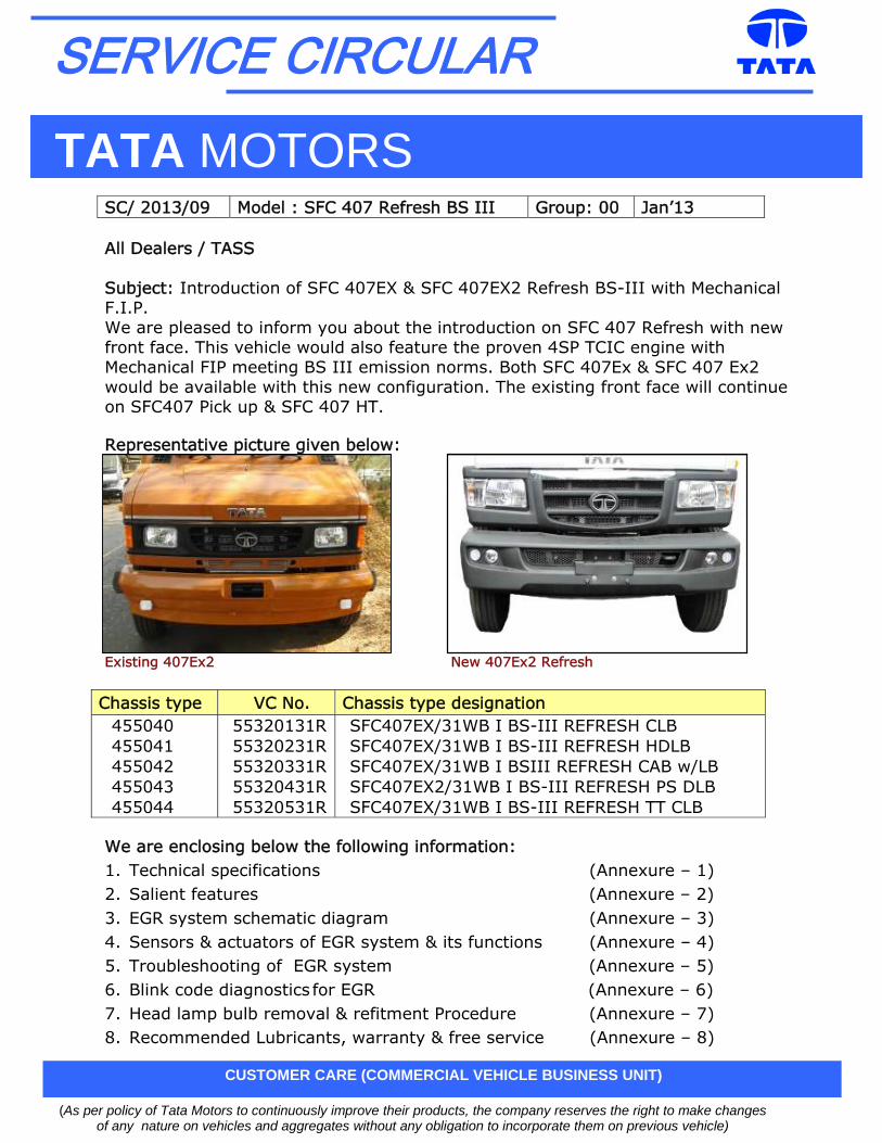
All Dealers / TASS Subject: Introduction of SFC 407EX & SFC 407EX2 Refresh BS-III with Mechanical F.I.P. We are pleased to inform you about the introduction on SFC 407 Refresh with new front face. This vehicle would also feature the proven 4SP TCIC engine with Mechanical FIP meeting BS III emission norms. Both SFC 407Ex & SFC 407 Ex2 would be available with this new configuration. The existing front face will continue on SFC407 Pick up & SFC 407 HT. Representative picture given below:
Existing 407Ex2 New 407Ex2 Refresh
Chassis type VC No. Chassis type designation 455040 455041 455042 455043 455044
55320131R 55320231R 55320331R 55320431R 55320531R
SFC407EX/31WB I BS-III REFRESH CLB SFC407EX/31WB I BS-III REFRESH HDLB SFC407EX/31WB I BSIII REFRESH CAB w/LB SFC407EX2/31WB I BS-III REFRESH PS DLB SFC407EX/31WB I BS-III REFRESH TT CLB
We are enclosing below the following information: 1. Technical specifications (Annexure – 1) 2. Salient features (Annexure – 2) 3. EGR system schematic diagram (Annexure – 3) 4. Sensors & actuators of EGR system & its functions (Annexure – 4) 5. Troubleshooting of EGR system (Annexure – 5) 6. Blink code diagnostics for EGR (Annexure – 6) 7. Head lamp bulb removal & refitment Procedure (Annexure – 7) 8. Recommended Lubricants, warranty & free service (Annexure – 8)
SC/ 2013/09 Model : SFC 407 Refresh BS III Group: 00 Jan’13
(As per policy of Tata Motors to continuously improve their products, the company reserves the right to make changes of any nature on vehicles and aggregates without any obligation to incorporate them on previous vehicle)
CUSTOMER CARE (COMMERCIAL VEHICLE BUSINESS UNIT)
TATA MOTORS
SERVICE CIRCULAR
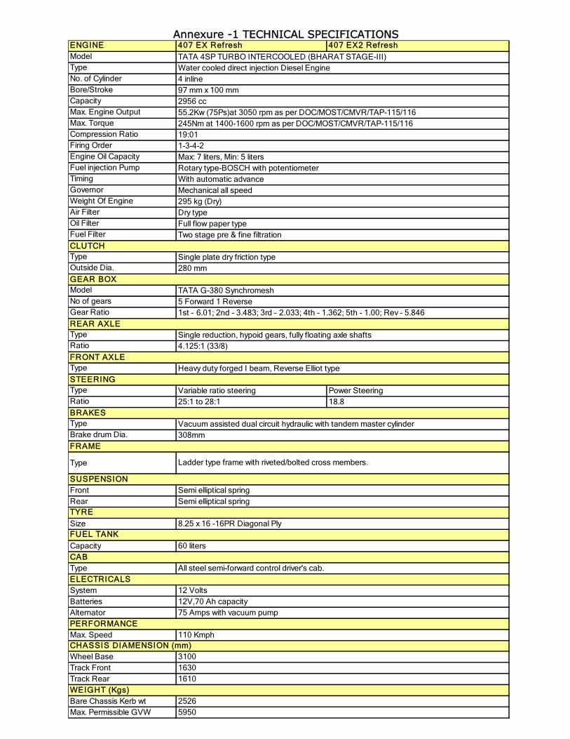
Annexure -1 TECHNICAL SPECIFICATIONS ENGINE 407 EX Refresh 407 EX2 RefreshModelTypeNo. of CylinderBore/StrokeCapacityMax. Engine OutputMax. TorqueCompression RatioFiring OrderEngine Oil CapacityFuel injection PumpTimingGovernorWeight Of EngineAir FilterOil FilterFuel Filter
TypeOutside Dia.
ModelNo of gearsGear Ratio
TypeRatio
Type
Type Variable ratio steering Power SteeringRatio 25:1 to 28:1 18.8
TypeBrake drum Dia.
Type
Front RearTYRE
SizeFUEL TANK
Capacity
Type
System BatteriesAlternator
Max. Speed
Wheel BaseTrack FrontTrack Rear
Bare Chassis Kerb wt Max. Permissible GVW
1610WEIGHT (Kgs)
25265950
75 Amps with vacuum pumpPERFORMANCE
110 KmphCHASSIS DIAMENSION (mm)
31001630
Semi elliptical spring
8.25 x 16 -16PR Diagonal Ply
60 litersCAB
All steel semi-forward control driver's cab. ELECTRICALS
12 Volts12V,70 Ah capacity
BRAKESVacuum assisted dual circuit hydraulic with tandem master cylinder308mm
FRAME
Ladder type frame with riveted/bolted cross members.
SUSPENSIONSemi elliptical spring
REAR AXLESingle reduction, hypoid gears, fully floating axle shafts4.125:1 (33/8)
FRONT AXLEHeavy duty forged I beam, Reverse Elliot type
STEERING
Single plate dry friction type280 mm
GEAR BOXTATA G-380 Synchromesh5 Forward 1 Reverse1st – 6.01; 2nd - 3.483; 3rd – 2.033; 4th - 1.362; 5th - 1.00; Rev - 5.846
Mechanical all speed295 kg (Dry)Dry typeFull flow paper typeTwo stage pre & fine filtration
CLUTCH
245Nm at 1400-1600 rpm as per DOC/MOST/CMVR/TAP-115/116 19:011-3-4-2Max: 7 liters, Min: 5 litersRotary type-BOSCH with potentiometerWith automatic advance
TATA 4SP TURBO INTERCOOLED (BHARAT STAGE-III)Water cooled direct injection Diesel Engine4 inline97 mm x 100 mm2956 cc55.2Kw (75Ps)at 3050 rpm as per DOC/MOST/CMVR/TAP-115/116
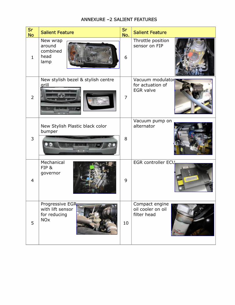
ANNEXURE –2 SALIENT FEATURES
Sr No Salient Feature Sr
No. Salient Feature
1
New wrap around combined head lamp
6
Throttle position sensor on FIP
2
New stylish bezel & stylish centre grill
7
Vacuum modulator for actuation of EGR valve
3
New Stylish Plastic black color bumper
8
Vacuum pump on alternator
4
Mechanical FIP & governor 9
EGR controller ECU
5
Progressive EGR with lift sensor for reducing NOx 10
Compact engine oil cooler on oil filter head
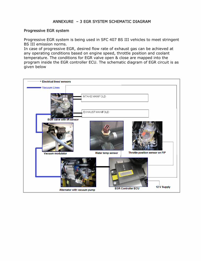
ANNEXURE – 3 EGR SYSTEM SCHEMATIC DIAGRAM Progressive EGR system Progressive EGR system is being used in SFC 407 BS III vehicles to meet stringent BS III emission norms. In case of progressive EGR, desired flow rate of exhaust gas can be achieved at any operating conditions based on engine speed, throttle position and coolant temperature. The conditions for EGR valve open & close are mapped into the program inside the EGR controller ECU. The schematic diagram of EGR circuit is as given below
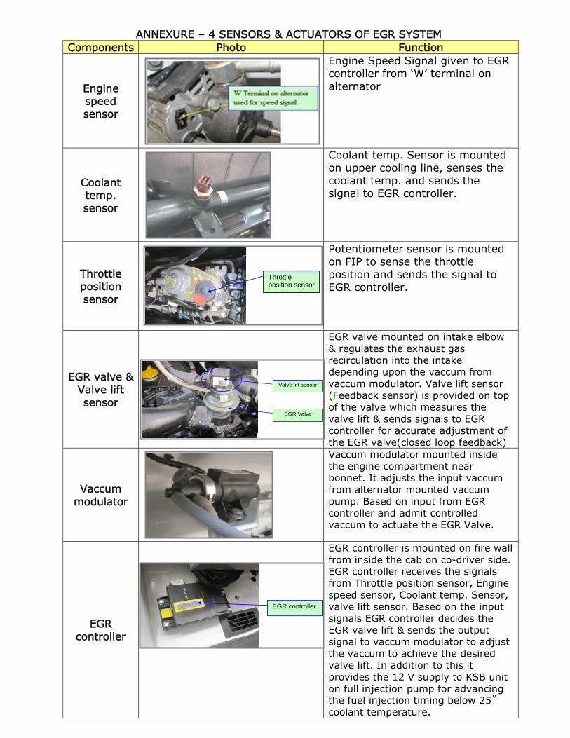
ANNEXURE – 4 SENSORS & ACTUATORS OF EGR SYSTEM Components Photo Function
Engine speed sensor
Engine Speed Signal given to EGR controller from ‘W’ terminal on alternator
Coolant temp. sensor
Coolant temp. Sensor is mounted on upper cooling line, senses the coolant temp. and sends the signal to EGR controller.
Throttle position sensor
Potentiometer sensor is mounted on FIP to sense the throttle position and sends the signal to EGR controller.
EGR valve & Valve lift sensor
EGR valve mounted on intake elbow & regulates the exhaust gas recirculation into the intake depending upon the vaccum from vaccum modulator. Valve lift sensor (Feedback sensor) is provided on top of the valve which measures the valve lift & sends signals to EGR controller for accurate adjustment of the EGR valve(closed loop feedback)
Vaccum modulator
Vaccum modulator mounted inside the engine compartment near bonnet. It adjusts the input vaccum from alternator mounted vaccum pump. Based on input from EGR controller and admit controlled vaccum to actuate the EGR Valve.
EGR controller
EGR controller is mounted on fire wall from inside the cab on co-driver side. EGR controller receives the signals from Throttle position sensor, Engine speed sensor, Coolant temp. Sensor, valve lift sensor. Based on the input signals EGR controller decides the EGR valve lift & sends the output signal to vaccum modulator to adjust the vaccum to achieve the desired valve lift. In addition to this it provides the 12 V supply to KSB unit on full injection pump for advancing the fuel injection timing below 25˚ coolant temperature.
Throttle position sensor
Valve lift sensor
EGR Valve
EGR controller
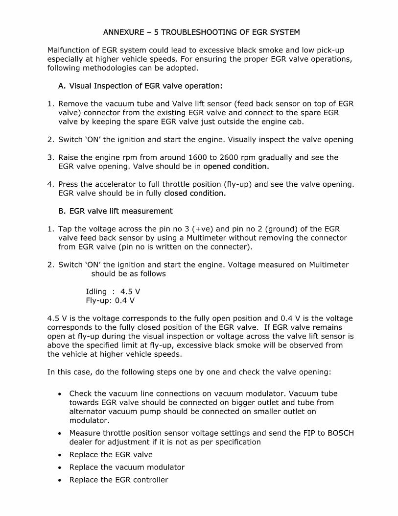
ANNEXURE – 5 TROUBLESHOOTING OF EGR SYSTEM
Malfunction of EGR system could lead to excessive black smoke and low pick-up especially at higher vehicle speeds. For ensuring the proper EGR valve operations, following methodologies can be adopted.
A. Visual Inspection of EGR valve operation: 1. Remove the vacuum tube and Valve lift sensor (feed back sensor on top of EGR
valve) connector from the existing EGR valve and connect to the spare EGR valve by keeping the spare EGR valve just outside the engine cab.
2. Switch ‘ON’ the ignition and start the engine. Visually inspect the valve opening 3. Raise the engine rpm from around 1600 to 2600 rpm gradually and see the
EGR valve opening. Valve should be in opened condition. 4. Press the accelerator to full throttle position (fly-up) and see the valve opening.
EGR valve should be in fully closed condition.
B. EGR valve lift measurement 1. Tap the voltage across the pin no 3 (+ve) and pin no 2 (ground) of the EGR
valve feed back sensor by using a Multimeter without removing the connector from EGR valve (pin no is written on the connecter).
2. Switch ‘ON’ the ignition and start the engine. Voltage measured on Multimeter
should be as follows
Idling : 4.5 V Fly-up: 0.4 V
4.5 V is the voltage corresponds to the fully open position and 0.4 V is the voltage corresponds to the fully closed position of the EGR valve. If EGR valve remains open at fly-up during the visual inspection or voltage across the valve lift sensor is above the specified limit at fly-up, excessive black smoke will be observed from the vehicle at higher vehicle speeds. In this case, do the following steps one by one and check the valve opening:
• Check the vacuum line connections on vacuum modulator. Vacuum tube towards EGR valve should be connected on bigger outlet and tube from alternator vacuum pump should be connected on smaller outlet on modulator.
• Measure throttle position sensor voltage settings and send the FIP to BOSCH dealer for adjustment if it is not as per specification
• Replace the EGR valve
• Replace the vacuum modulator
• Replace the EGR controller
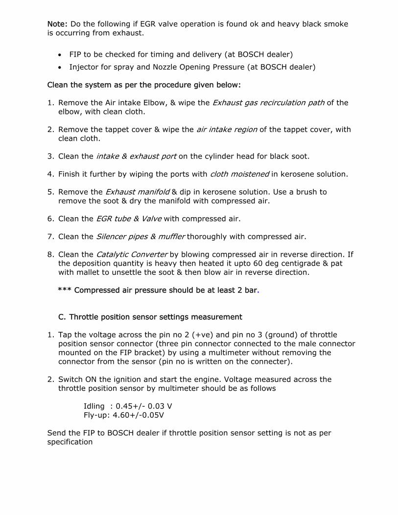
Note: Do the following if EGR valve operation is found ok and heavy black smoke is occurring from exhaust.
• FIP to be checked for timing and delivery (at BOSCH dealer)
• Injector for spray and Nozzle Opening Pressure (at BOSCH dealer) Clean the system as per the procedure given below: 1. Remove the Air intake Elbow, & wipe the Exhaust gas recirculation path of the
elbow, with clean cloth. 2. Remove the tappet cover & wipe the air intake region of the tappet cover, with
clean cloth. 3. Clean the intake & exhaust port on the cylinder head for black soot. 4. Finish it further by wiping the ports with cloth moistened in kerosene solution. 5. Remove the Exhaust manifold & dip in kerosene solution. Use a brush to
remove the soot & dry the manifold with compressed air. 6. Clean the EGR tube & Valve with compressed air. 7. Clean the Silencer pipes & muffler thoroughly with compressed air. 8. Clean the Catalytic Converter by blowing compressed air in reverse direction. If
the deposition quantity is heavy then heated it upto 60 deg centigrade & pat with mallet to unsettle the soot & then blow air in reverse direction.
*** Compressed air pressure should be at least 2 bar.
C. Throttle position sensor settings measurement 1. Tap the voltage across the pin no 2 (+ve) and pin no 3 (ground) of throttle
position sensor connector (three pin connector connected to the male connector mounted on the FIP bracket) by using a multimeter without removing the connector from the sensor (pin no is written on the connecter).
2. Switch ON the ignition and start the engine. Voltage measured across the
throttle position sensor by multimeter should be as follows
Idling : 0.45+/- 0.03 V Fly-up: 4.60+/-0.05V
Send the FIP to BOSCH dealer if throttle position sensor setting is not as per specification
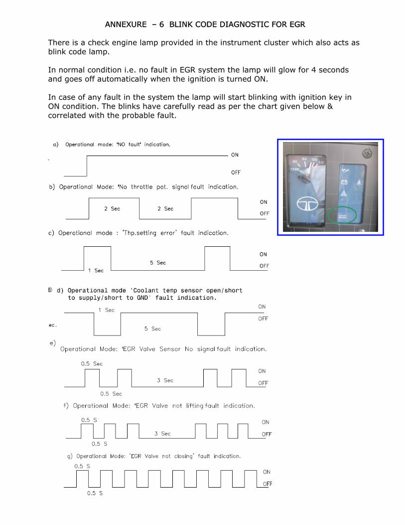
ANNEXURE – 6 BLINK CODE DIAGNOSTIC FOR EGR There is a check engine lamp provided in the instrument cluster which also acts as blink code lamp. In normal condition i.e. no fault in EGR system the lamp will glow for 4 seconds and goes off automatically when the ignition is turned ON. In case of any fault in the system the lamp will start blinking with ignition key in ON condition. The blinks have carefully read as per the chart given below & correlated with the probable fault.
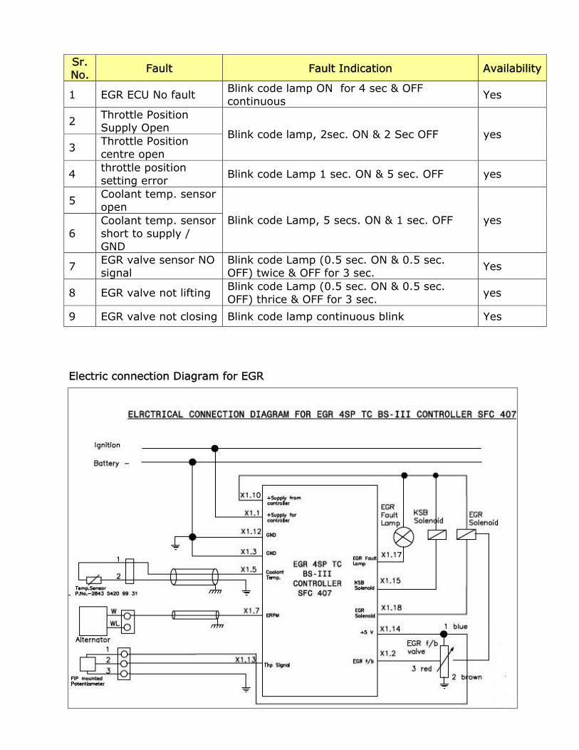
Electric connection Diagram for EGR
Sr. No.
Fault Fault Indication Availability
1 EGR ECU No fault Blink code lamp ON for 4 sec & OFF continuous Yes
2 Throttle Position Supply Open
Blink code lamp, 2sec. ON & 2 Sec OFF yes 3
Throttle Position centre open
4 throttle position setting error
Blink code Lamp 1 sec. ON & 5 sec. OFF yes
5 Coolant temp. sensor open
Blink code Lamp, 5 secs. ON & 1 sec. OFF yes 6
Coolant temp. sensor short to supply / GND
7 EGR valve sensor NO signal
Blink code Lamp (0.5 sec. ON & 0.5 sec. OFF) twice & OFF for 3 sec. Yes
8 EGR valve not lifting Blink code Lamp (0.5 sec. ON & 0.5 sec. OFF) thrice & OFF for 3 sec. yes
9 EGR valve not closing Blink code lamp continuous blink Yes
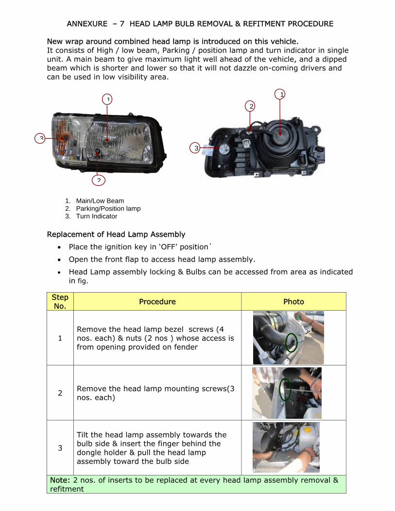
ANNEXURE – 7 HEAD LAMP BULB REMOVAL & REFITMENT PROCEDURE New wrap around combined head lamp is introduced on this vehicle. It consists of High / low beam, Parking / position lamp and turn indicator in single unit. A main beam to give maximum light well ahead of the vehicle, and a dipped beam which is shorter and lower so that it will not dazzle on-coming drivers and can be used in low visibility area.
Replacement of Head Lamp Assembly
• Place the ignition key in ‘OFF’ position`
• Open the front flap to access head lamp assembly.
• Head Lamp assembly locking & Bulbs can be accessed from area as indicated in fig.
Step No.
Procedure Photo
1 Remove the head lamp bezel screws (4 nos. each) & nuts (2 nos ) whose access is from opening provided on fender
2 Remove the head lamp mounting screws(3 nos. each)
3
Tilt the head lamp assembly towards the bulb side & insert the finger behind the dongle holder & pull the head lamp assembly toward the bulb side
Note: 2 nos. of inserts to be replaced at every head lamp assembly removal & refitment
1
3
2
3
1
2
1. Main/Low Beam 2. Parking/Position lamp 3. Turn Indicator
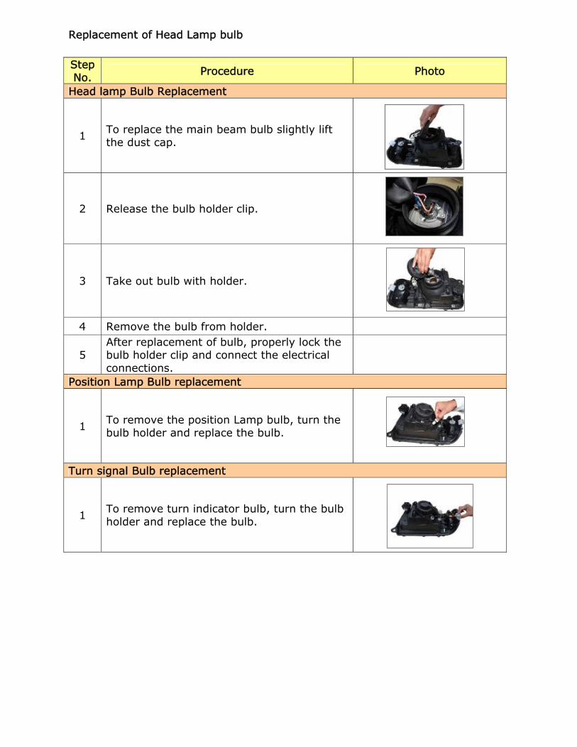
Replacement of Head Lamp bulb
Step No. Procedure Photo
Head lamp Bulb Replacement
1 To replace the main beam bulb slightly lift the dust cap.
2 Release the bulb holder clip.
3 Take out bulb with holder.
4 Remove the bulb from holder.
5 After replacement of bulb, properly lock the bulb holder clip and connect the electrical connections.
Position Lamp Bulb replacement
1 To remove the position Lamp bulb, turn the bulb holder and replace the bulb.
Turn signal Bulb replacement
1 To remove turn indicator bulb, turn the bulb holder and replace the bulb.
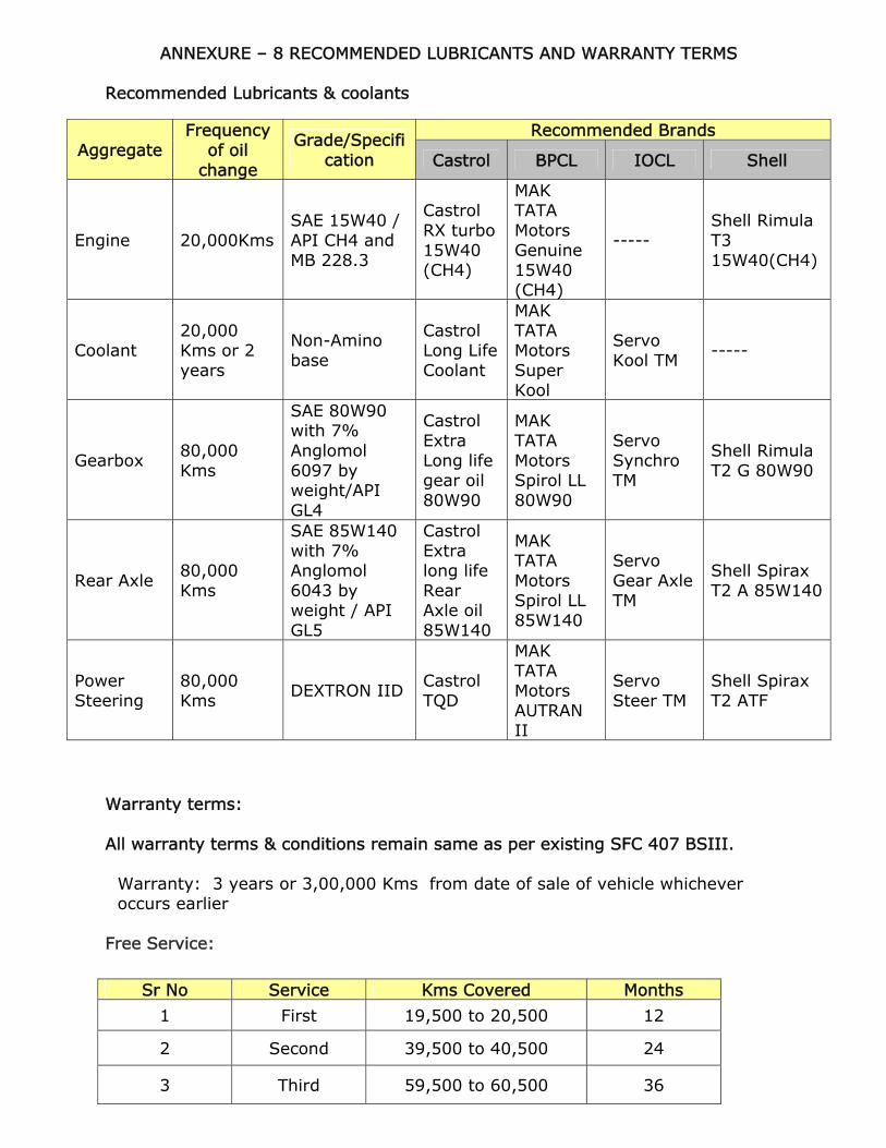
ANNEXURE – 8 RECOMMENDED LUBRICANTS AND WARRANTY TERMS
Recommended Lubricants & coolants
Warranty terms: All warranty terms & conditions remain same as per existing SFC 407 BSIII.
Warranty: 3 years or 3,00,000 Kms from date of sale of vehicle whichever occurs earlier
Free Service:
Aggregate Frequency
of oil change
Grade/Specification
Recommended Brands
Castrol BPCL IOCL Shell
Engine 20,000Kms SAE 15W40 / API CH4 and MB 228.3
Castrol RX turbo 15W40 (CH4)
MAK TATA Motors Genuine 15W40 (CH4)
----- Shell Rimula T3 15W40(CH4)
Coolant 20,000 Kms or 2 years
Non-Amino base
Castrol Long Life Coolant
MAK TATA Motors Super Kool
Servo Kool TM -----
Gearbox 80,000 Kms
SAE 80W90 with 7% Anglomol 6097 by weight/API GL4
Castrol Extra Long life gear oil 80W90
MAK TATA Motors Spirol LL 80W90
Servo Synchro TM
Shell Rimula T2 G 80W90
Rear Axle 80,000 Kms
SAE 85W140 with 7% Anglomol 6043 by weight / API GL5
Castrol Extra long life Rear Axle oil 85W140
MAK TATA Motors Spirol LL 85W140
Servo Gear Axle TM
Shell Spirax T2 A 85W140
Power Steering
80,000 Kms
DEXTRON IID Castrol TQD
MAK TATA Motors AUTRAN II
Servo Steer TM
Shell Spirax T2 ATF
Sr No Service Kms Covered Months
1 First 19,500 to 20,500 12
2 Second 39,500 to 40,500 24
3 Third 59,500 to 60,500 36