Embed Size (px)
Citation preview
SBIG Universal Driver/Library Version 4.60 Build 9 November 18, 2008
Santa Barbara Instrument Group 147A Castilian Drive
Santa Barbara, CA 93117 Phone: (805) 571-7244 Fax: (805) 571-1147
Web: <www.sbig.com> EMail: <[email protected]>
Santa Barbara Instrument Group Universal Driver Application Note
Page 2
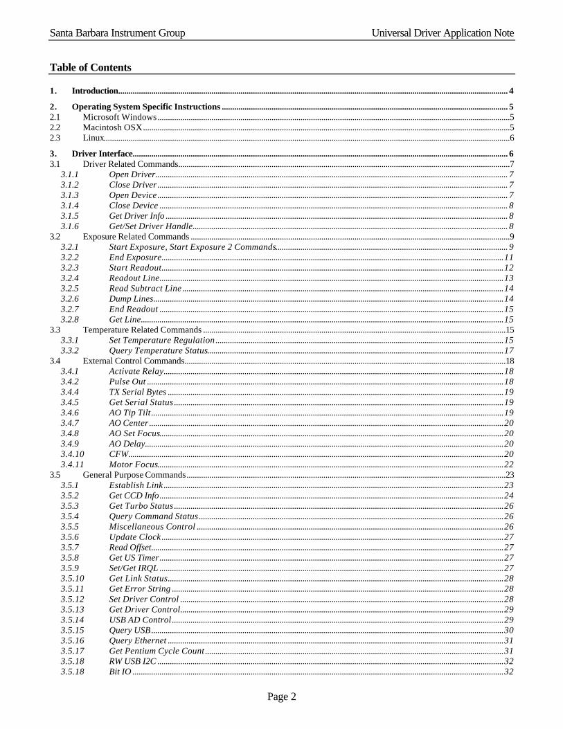
Table of Contents
1. Introduction............................................................................................................................................................................................ 4 2. Operating System Specific Instructions .......................................................................................................................................... 5 2.1 Microsoft Windows..........................................................................................................................................................................5 2.2 Macintosh OSX.................................................................................................................................................................................5 2.3 Linux....................................................................................................................................................................................................6 3. Driver Interface..................................................................................................................................................................................... 6 3.1 Driver Related Commands................................................................................................................................................................7
3.1.1 Open Driver.......................................................................................................................................................................... 7 3.1.2 Close Driver......................................................................................................................................................................... 7 3.1.3 Open Device......................................................................................................................................................................... 7 3.1.4 Close Device ........................................................................................................................................................................ 8 3.1.5 Get Driver Info ..................................................................................................................................................................... 8 3.1.6 Get/Set Driver Handle........................................................................................................................................................ 8
3.2 Exposure Related Commands ..........................................................................................................................................................9 3.2.1 Start Exposure, Start Exposure 2 Commands................................................................................................................ 9 3.2.2 End Exposure.....................................................................................................................................................................11 3.2.3 Start Readout.....................................................................................................................................................................12 3.2.4 Readout Line......................................................................................................................................................................13 3.2.5 Read Subtract Line...........................................................................................................................................................14 3.2.6 Dump Lines.........................................................................................................................................................................14 3.2.7 End Readout ......................................................................................................................................................................15 3.2.8 Get Line...............................................................................................................................................................................15
3.3 Temperature Related Commands ..................................................................................................................................................15 3.3.1 Set Temperature Regulation...........................................................................................................................................15 3.3.2 Query Temperature Status...............................................................................................................................................17
3.4 External Control Commands...........................................................................................................................................................18 3.4.1 Activate Relay....................................................................................................................................................................18 3.4.2 Pulse Out ............................................................................................................................................................................18 3.4.4 TX Serial Bytes ..................................................................................................................................................................19 3.4.5 Get Serial Status ...............................................................................................................................................................19 3.4.6 AO Tip Tilt ..........................................................................................................................................................................19 3.4.7 AO Center...........................................................................................................................................................................20 3.4.8 AO Set Focus......................................................................................................................................................................20 3.4.9 AO Delay.............................................................................................................................................................................20 3.4.10 CFW.....................................................................................................................................................................................20 3.4.11 Motor Focus.......................................................................................................................................................................22
3.5 General Purpose Commands..........................................................................................................................................................23 3.5.1 Establish Link....................................................................................................................................................................23 3.5.2 Get CCD Info......................................................................................................................................................................24 3.5.3 Get Turbo Status ...............................................................................................................................................................26 3.5.4 Query Command Status ...................................................................................................................................................26 3.5.5 Miscellaneous Control ....................................................................................................................................................26 3.5.6 Update Clock.....................................................................................................................................................................27 3.5.7 Read Offset..........................................................................................................................................................................27 3.5.8 Get US Timer......................................................................................................................................................................27 3.5.9 Set/Get IRQL ......................................................................................................................................................................27 3.5.10 Get Link Status..................................................................................................................................................................28 3.5.11 Get Error String ................................................................................................................................................................28 3.5.12 Set Driver Control ............................................................................................................................................................28 3.5.13 Get Driver Control............................................................................................................................................................29 3.5.14 USB AD Control ................................................................................................................................................................29 3.5.15 Query USB..........................................................................................................................................................................30 3.5.16 Query Ethernet ..................................................................................................................................................................31 3.5.17 Get Pentium Cycle Count ................................................................................................................................................31 3.5.18 RW USB I2C .......................................................................................................................................................................32 3.5.18 Bit IO ...................................................................................................................................................................................32
Santa Barbara Instrument Group Universal Driver Application Note
Page 3
4. Windows Based Utility Programs ....................................................................................................................................................32 4.1 SBIGDriverChecker.exe ...................................................................................................................................................................33 4.2 EthSim.exe .........................................................................................................................................................................................33 4.3 SBIGUDRVJournalRx.exe ...............................................................................................................................................................33 4.4 SetClock.exe .....................................................................................................................................................................................34 4.5 GetPortD.exe .....................................................................................................................................................................................34 5. Supporting New Cameras and Accessories ...................................................................................................................................34 5.1 Supporting the ST-L.......................................................................................................................................................................34 5.2 Supporting the Single Shot Color Cameras .................................................................................................................................35 5.3 Supporting the ST-402 Camera and CFW-402 Filter Wheel......................................................................................................36 5.4 Supporting the CFW-10 Color Filter Wheel................................................................................................................................36 5.5 Supporting the I2C based AO Accessories .................................................................................................................................36 5.6 Supporting the I2C based CFW-9, CFW-L8 and CFW-L8G Color Filter Wheels ...................................................................37 5.7 Supporting the I2C based Motor Focus Accessory ..................................................................................................................37 5.8 Supporting the I2C based low-cost A0-8.....................................................................................................................................37 5.9 Supporting the ST-4000XCM Single Shot Color Camera ..........................................................................................................37 5.10 Supporting the STX Cameras ........................................................................................................................................................38 6. Revision History..................................................................................................................................................................................38
Santa Barbara Instrument Group Universal Driver Application Note
Page 4
1. Introduction This document describes the software interface to Santa Barbara Instrument Group's Universal Driver Library (SBIGUDRV). The SBIGUDRV driver supports all of SBIG’s Parallel, Ethernet and USB based cameras and accessories. The driver/library is available for Microsoft Windows, Macintosh OSX1 and Linux. Windows support is for the 32 bit Windows 952/98/Me/NT/2000/XP. The various development kits and supplemental downloads may contain the following files:
SBIGUDRV.H - Use this include file with all programs calling the driver. It includes the function prototype and many struct definitions for interfacing to the driver. You need to set the TARGET variable based upon your target environment:
Win 95/98/ME/NT/2000/XP – ENV_WIN Macintosh OSX – ENV_MACOSX Linux – ENC_LINUX One of the things we do with our development is create an LSBIGUDRV.H file where we set TARGET and then include the SBIGUDRV.H file. By including LSBIGUDRV.H instead of SBIGUDRV.H you can replace the SBIGUDRV.H file when it gets revised without having to edit it every time to reset the TARGET.
SBIGUDRV.LIB - This is an import library that you link with your 32 bit Windows program. Include this in your "project" file.
Windows Development Kit – Contains everything you need to start developing software for the Windows platform including the Windows Tool described below.
Mac OSX Development Kit – Contains a USB driver installation package. Running the installer package installs the USB drivers and a Framework that implements the Universal Driver.
Linux Development Kit – Contains a gzipped tar archive with the Universal Driver as a shared library and low-level Parallel Port and USB drivers.
SBIG Driver Checker/Installer – This is an installer for a Windows utility program that checks the drivers installed on a system against the latest drivers in its SBIG Drivers directory. A complete description is in Section 3. The drivers installed include:
SBIGUDRV.DLL - This is a 32 bit Windows DLL. It is built with the “stdcall” calling convention, which means it can be called from Visual C++ or Visual Basic.
SBIGUDRV.VXD - This is a protected mode low-level parallel port driver for 32 bit Windows 95/98/Me that is used in conjunction with parallel port cameras and the SBIGUDRV.DLL.
SBIGUDRV.SYS – This is a low-level parallel port driver for Windows NT/2000/XP that is used in conjunction with parallel port cameras and the SBIGUDRV.DLL.
SBIGUSBE.SYS, SBIGULDR.SYS, SBIGLLDR.SYS, SBIGFLDR.SYS – These files are the low-level USB driver and firmware loaders for USB based cameras. Please refer to the “Installing USB.PDF” Application Note for how to install these drivers.
SBIGUSBE.INF – This is the USB driver information file. \Tools – This directory contains some Windows utility programs that will help you get your custom program
up and running with the SBIG Universal Driver/Library. See section 3 for a description of each of these tools.
Visual C++ Sample Program – Includes a sample Visual Studio 6 project. Visual Basic Sample Programs – Includes some sample Visual Basic programs.
1 Macintosh OSX does not support parallel port based cameras as these ports do not exist in the Mac world. Users with
Parallel Port based cameras can use their cameras on Ethernet equipped Macs with OSX by using SBIG’s optional Ethernet to Parallel (E2P) Adapter.
2 There is no support for USB based cameras under Windows 95 or NT.

Santa Barbara Instrument Group Universal Driver Application Note
Page 5
SBIG C++ Sample Classes – Includes sample source code for CSBIGCamera and CSBIGImage classes.
2. Operating System Specific Instructions This section contains Operating System specific instruction on how to install the drivers and how to build projects that include the SBIG Universal Driver Library.
2.1 Microsoft Windows SBIG provides the SBIG Driver Checker utility for installing the USB and Parallel port drivers under Windows. This process is documented in the “Installing USB.pdf” file in the DOCS directory. It’s critical under Windows that you install the drivers correctly. Please follow that document to the letter. Once the drivers have been installed it’s a good idea to run SBIG’s CCDOps software to make sure you can talk to your camera. If you don’t have CCDOps you can download it from our web site. This will confirm the proper driver installation and insure your camera is working correctly. Once the drivers are installed and your camera is working follow the instructions below to add the SBIG Universal Driver to your software project: Visual C
• Include the SBIGUDRV.H (or LSBIGUDRV.H) file in your C/C++ files that need to call the driver to get the function prototype, enumeration declarations and struct definitions.
• Add the SBIGUDRV.LIB file to your project so your project will link with the SBIGUDRV.DLL that was installed into the \Windows\System directory
Visual BASIC
• Add the SBIGTypes.bas file to your Visual Basic project for the function declaration, enumeration declarations and type definitions.
• Note that Visual BASIC has no unsigned types so pixel data which the driver treats as an unsigned short (values 0 to 65535) but Visual BASIC treats as signed (values –32768 to 32767) will have to be converted to long. Signed values 0 to 32767 convert directly whereas signed values –32768 to –1 convert to 32768 to 65535 respectively. Thus negative signed short pixel values convert to signed long values by “signed long = 65536 – signed short”.
2.2 Macintosh OSX SBIG provides the SBIG Driver Installer.pkg for installing the low-level USB drivers and the SBIG Universal Driver Framework. Double click this file to install the drivers and library. Once the drivers have been installed it’s a good idea to run SBIG’s CCDOps Lite for OSX software to make sure you can talk to your camera. If you don’t have CCDOps Lite you can download it from our web site. This will confirm the proper driver installation and insure your camera is working correctly. Once the drivers are installed and your camera is working with CCDOps Lite add: #include <SBIGUDrv/sbigudrv.h> to any source code that calls the SBIG Universal Driver Library to bring in the enumerations, struct definitions and function prototype. Also add to the project the: /Library/Frameworks/SBIGUDrv.framework framework file to get the program to link.
Santa Barbara Instrument Group Universal Driver Application Note
Page 6
2.3 Linux Please see the README.txt file included in the Linux Development kit for detailed instructions on how to install the SBIG Universal Driver Library on your Linux system.
3. Driver Interface The software interface to the Universal Driver Library is through single external function that takes a short integer Command and pointers to command Parameter and command Results structs. The driver acts upon the Command and Parameters struct and fills in the Results struct. The memory allocation for these structs is the responsibility of the calling program.
The C prototype for the function is shown in the SBIGUDRV.H file and takes the form:
short SBIGUnivDrvCommand (short Command, void *Parameters , void *Results) where Command is the command to be executed and Parameters and Results are pointers to the structs. The function returns an error code indicating whether the camera was able to initiate or complete the command. Note that enumerated types exist in the SBIGUDRV.H file for the Command (PAR_COMMAND) and function return result (PAR_ERROR) as well as many of the fields in the various Parameters and Results structs.
The commands supported by the driver are grouped into the following sections discussed individually below:
• Driver Related Commands • Exposure Related Commands • Temperature Related Commands • External Control Commands • General Purpose Commands
Getting back to the driver, it is written and documented assuming you are programming and proficient in C. As you can see, the function prototype is a C function (not C++), and as you will see the Parameters and Results parameters will end up being pointers to structs using the following data types within the structs:
LOGICAL - unsigned short (2 bytes) with 0 = FALSE and 1 = TRUE enum - Enumerated unsigned short (2 bytes) with an allowed set of values short - signed short (2 bytes) ushort - unsigned short (2 bytes) long - signed long (4 bytes) ulong - unsigned long (4 bytes)
Some commands don't require Parameters structs and some don't require Results structs. In those cases you should pass a NULL pointer to the driver. The supported commands are discussed in the sections below. For each command the Parameters and Results structs are shown except in the case where one or both do not exist. The function error return codes for each of the commands will vary from command to command. For each command that doesn’t operate immediately, a command status is maintained internally by the driver, and can be monitored with the Query Command Status command. The command status for each of the commands varies from command to command but in general will be from one of the following:
Santa Barbara Instrument Group Universal Driver Application Note
Page 7
0 = Idle 1 = Command In Progress
3.1 Driver Related Commands The Commands in this section are used to open and close the driver and get driver related information. At the application level you must Open the Driver (allowing access to the top level of the driver) and then Open the Device (selecting the hardware interface) in order to communicate with the camera.
3.1.1 Open Driver The Open Driver command is used to initialize the driver and should be your first call to the driver. It takes no Parameters and returns no Results. Just pass NULL pointers to the Parameters and Results arguments of the SBIGUDrvCommand function when you call it.
3.1.2 Close Driver The Close Driver command is used to close the driver and should be your last call to the driver. There must be one call to Close Driver for each call to Open Driver. This command takes no Parameters and returns no Results. Just pass NULL pointers to the Parameters and Results arguments of the SBIGUDrvCommand function when you call it.
3.1.3 Open Device The Open Device command is used to load and initialize the low-level driver. You will typically call this second (after Open Driver). Parameters Struct: struct OpenDeviceParams {
enum deviceType (see the SBIG_DEVICE_TYPE enum) 0 = unused 1,2,3 – LPT 1,2,3 0x7F00 – USB 0x7F01 – Ethernet 0x7F02 – USB1 0x7F03 – USB2 0x7F04 – USB3 0x7F05 – USB4
ushort lptBaseAddress – for LPT1,2,3 base port address of the LPT port ulong ipAddress - for Ethernet the IP address of the camera/accessory
} This command returns no Results. Just pass a NULL pointer to the Results argument of the SBIGUDrvCommand function when you call it. Notes:
• The lptBaseAddress is required for LPT1,2,3 under Windows 95/98/Me. This is typically 0x378 for LPT1 and 0x278 for LPT2 but can vary from machine to machine and can be found from the Device Manager control panel. Under Windows NT/2000/XP you can leave this set to 0 as the driver gets this information from the OS.
Santa Barbara Instrument Group Universal Driver Application Note
Page 8
• The ipAddress is required for Ethernet. Use the four bytes of the long with the most significant byte specifying the first part of the address. For example if the desired IP address is 192.168.0.1 use 0xC0A80001 (0xC0=192, 0xA8 = 168, etc.)
• When using the Open Device command for opening USB devices, specifying USB (DEV_USB = 0x7F00) opens the next available USB device which may not be what you want in situations with multiple USB cameras. In these cases use the Query USB command first to see what model cameras are available then specify USB1, USB2, USB3 or USB4 to open those specific cameras.
3.1.4 Close Device The Close Driver command is used to close the low-level driver. You will typically call this second to last (right before Close Driver). There must be one call for Close Device for every call to Open Device. The Close Device command takes no Parameters and returns no Results. Just pass NULL pointers to the Parameters and Results arguments of the SBIGUDrvCommand function when you call it.
3.1.5 Get Driver Info The Get Driver Info command is used to determine the version and capabilities of the DLL/Driver. For future expandability this command allows you to request several types of information. Initially the standard request and extended requests will be supported but as the driver evolves additional requests will be added.
Parameters Struct: struct GetDriverInfoParams {
enum request - type of driver information desired (see the DRIVER_REQUEST enum) 0 = Standard request 1 = Extended request 2 = USB loader request 3, etc. - reserved for future expansion
}
Standard, Extended and USB Loader Results Struct: struct GetDriverInfoResults0 {
ushort version - driver version in BCD with the format XX.XX char name[64] - driver name, null terminated string ushort maxRequest - maximum request response available from this driver
} The Standard request returns the version and name information for the high level SBIG Universal Driver Library. The Extended request returns the version and name information for the low level LPT or USB driver. With linked USB cameras the USB Loader request returns the version and name information for the USB Loader driver.
3.1.6 Get/Set Driver Handle The Get/Set Driver Handle commands are for use by applications that wish to talk to multiple cameras on various ports at the same time. If your software only wants to talk to one camera at a time you can ignore these commands.
The Get Driver Handle command takes a NULL Parameters pointer and a pointer to a GetDriverHandleResults struct for Results. The Set Driver Handle command takes a pointer to a SetDriverHandleParams struct for Parameters and a NULL pointer for Results. To establish links to multiple cameras do the following sequence:
Santa Barbara Instrument Group Universal Driver Application Note
Page 9
• Call Open Driver for Camera 1 • Call Open Device for Camera 1 • Call Establish Link for Camera 1 • Call Get Driver Handle and save the result as Handle1 • Call Set Driver Handle with INVALID_HANDLE_VALUE in the handle parameter • Call Open Driver for Camera 2 • Call Open Device for Camera 2 • Call Establish Link for Camera 2 • Call Get Driver Handle and save the result as Handle2
Then, when you want to talk to Camera 1, call Set Driver Handle with Handle1 and when you want to talk to Camera 2, call Set Driver Handle with Handle2. To shut down you must call Set Driver Handle, Close Device and Close Driver in that sequence for each camera. Each time you call Set Driver Handle with INVALID_HANDLE_VALUE you are allowing access to an additional camera up to a maximum of four cameras. These cameras can be on different LPT ports, multiple USB3 cameras or at different Ethernet addresses. There is a restriction though due to memory considerations. You can only have a single readout in process at a time for all cameras and CCDs within a camera. Readout begins with the Start Readout or Readout Line commands and ends with the End Readout command. If you try to do multiple interleaved readouts the data from the multiple cameras will be commingled. To avoid this, simply readout one camera/CCD at a time in an atomic process.
3.2 Exposure Related Commands The commands in the section are used to initiate, complete or cancel an exposure in the camera. For each exposure the camera needs to be instructed to start the exposure, stop the exposure, and readout the image on a row-by-row basis.
3.2.1 Start Exposure, Start Exposure 2 Commands The Start Exposure and Start Exposure 2 commands are used to initiate an exposure. The application specifies the exposure time, etc. and then monitors the exposure's progress with the Query Command Status command discussed below.
The Start Exposure is the original command from the days when the cameras did not have image buffers and can be used with all cameras before the advent of the STX. For the STX and later cameras with internal frame buffers we added the Start Exposure 2 command so you could specify the readout coordinates. The Start Exposure 2 command is required with the STX (and later frame buffer cameras) but can be used instead of the Start Exposure command with the older cameras as well.
Start Exposure Parameters Struct: struct StartExposureParams {
enum ccd - the CCD to use in the exposure (see the CCD_REQUEST enum) 0 = Imaging CCD 1 = Tracking CCD 2 = External Tracking CCD in ST-L
ulong exposureTime - integration time in hundredths of a second in the least significant 24 bits. The most significant 8 bits are bit-flags that modify the exposure as described below.
3 At this time supporting multiple USB cameras simultaneously is possible but not very convenient for the user. The first time
you open a USB device you will get the first camera connected to the computer, etc. At some point you would like to be able to enumerate the USB cameras. Use the Query USB Command to do that.
Santa Barbara Instrument Group Universal Driver Application Note
Page 10
enum abgState - antiblooming gate state during integration (see the ABG_STATE7 enum) 0 = Low during integration (ABG shut off) 1 = Clocked at low rate, 2 = Clocked at medium rate,3 = Clocked at high rate
enum openShutter – (see the SHUTTER_COMMAND enum) 0=Leave Shutter alone, 1=Open Shutter for Exposure and Close for Readout, 2=Close Shutter for Exposure and Readout
} Start Exposure 2 Parameters Struct: struct StartExposureParams2 {
enum ccd – same as StartExposureParams above. ulong exposureTime - – same as StartExposureParams above. enum abgState - – same as StartExposureParams above. enum openShutter – – same as StartExposureParams above. enum readoutMode - binning mode for readout (see READOUT_BINNING_MODE enum)
0 = No binning, high resolution 1 = 2x2 on-chip binning, medium resolution 2 = 3x3 on-chip binning, low resolution (ST-7/8/etc/237 only) 0xNN03 = Nx1 on-chip binning (ST-7/8/etc only) 0xNN04 = Nx2 on-chip binning (ST-7/8/etc only) 0xNN05 = Nx3 on-chip binning (ST-7/8/etc only) 6 = No binning, high resolution (ST-7/8/etc only) 7 = 2x2 binning with vertical binning off-chip (ST-7/8/etc only) 8 = 3x3 binning with vertical binning off-chip (ST-7/8/etc only) 9 = 9x9 binning (ST-7/8/etc only)
ushort top – top most row to readout (0 based) ushort left – left most pixel to readout (0 based) ushort height – image height in binned pixels ushort width – image width in binned pixels } The status for this command (from the Query Command Status Command) consists of the following two 2-bit fields:
b1b0 = Imaging CCD Status, 00 - CCD Idle, 10=In Progress, 11=Complete b3b2 = Internal and External Tracking CCD Status, 00 - CCD Idle, 10=In Progress,
11=Complete b15 = Trigger In Status, 1=Waiting for Trigger In, 0=Not waiting
Notes: • For the ST-7/ST-8/ST-9/ST-10/ST-1K/ST-402 add START_SKIP_VDD to the ccd parameter to
increase the image rep rate. This bypasses the time consuming reduction of the CCD’s Vdd which is normally used to reduce the readout amplifier glow for the imaging CCD. You’ll get a glow in the upper-left corner of the Imaging CCD but the readout rep rate will be higher. SBIG uses this in the Turbo focus mode.
• For the ST-7/ST-8/ST-9/ST-10/ST-1K the minimum allowable exposure is MIN_ST7_EXPOSURE (.12 seconds) when the openShutter item is 1. If you ask the driver to make a shorter exposure it will take a .12 second exposure.
Santa Barbara Instrument Group Universal Driver Application Note
Page 11
• For the ST-402 the minimum allowable exposure is MIN_402_EXPOSURE (40 milliseconds) when the openShutter item is 1. If you ask the driver to make a shorter exposure it will take a 40 millisecond second exposure.
• With Interline CCD cameras like the ST-2K, STL-11K with their electronic shutter the minimum allowable exposure is 0.01 seconds with Version 4.24 of the library and 0.001 seconds with version 4.27 and later.
• To see if a particular camera supports millisecond resolution exposures use the GetCCDInfo command Request 4 and check for and Electronic shutter.
• To get millisecond resolution exposures add EXP_MS_EXPOSURE to the exposureTime item and set the rest of the item to the exposure time in milliseconds. Millisecond exposures from 1 to 255 are possible. Millisecond exposures longer that 255 are rounded up to the nearest 100th of a second and programmed as a standard non-millisecond exposure.
• The maximum exposure is 655.35 seconds for Tracking CCD and 167,777.16 seconds for Imaging CCD.
• The abgState only affects the TC211 versions of the Tracking CCD on the ST-7/8/etc. and the Imaging CCD of the PixCel255.
• For the PixCel255, PixCel237, ST-1K and ST-402 you need to specify the Imaging CCD since the camera is not a dual CCD design.
• For the PixCel255 and PixCel237 the openShutter parameter is ignored and should be set to 0. Use the Pulse Out command to position the Vane/Filter Wheel.
• Bits b2/b3 of the status indicate the Tracking CCD status. With the ST-L and its two tracking CCDs (internal and external) only one set of status is maintained for ease of backwards compatibility. The moral of the story is always issue Start/Stop exposures in pairs for the Tracking CCDs or else these status bits can get confused.
• The ST-L’s external shutter in the Remote Tracking Head mimics the internal shutter. When the internal shutter is opened the external shutter is opened and vice versa.
• Adding EXP_WAIT_FOR_TRIGGER_IN to the exposureTime item causes the Universal Driver to wait for a Trigger Input signal from the camera before starting the Exposure. This status of the Trigger In signal is indicated by bit b15 of the command status.
• See the Notes section of the Start Readout command for additional data regarding the Start Exposure 2 command parameters.
3.2.2 End Exposure The End Exposure command is used after the integration is complete to prepare the CCD for readout or to terminate an exposure prematurely.
Parameters Struct: struct EndExposureParams {
enum ccd - the CCD to end the exposure (see the CCD_REQUEST enum) 0 = Imaging CCD 1 = Tracking CCD 2 = External Tracking CCD in ST-L
} Notes:
• The End Exposure command must be called at least once for each Start Exposure command issued. Several End Exposure commands can be issued without generating an error.
• For the ST-7/8/etc. the End Exposure command prepares the CCD for readout. This normally involves delaying a period of time waiting for the shutter motor to turn off. You can tell the driver to skip this
Santa Barbara Instrument Group Universal Driver Application Note
Page 12
delay by adding END_SKIP_DELAY to the ccd enum item in order to increase the image rep rate, but you should do this only when the shutter didn't move for both the light and dark images. This means you issued the Start Exposure command with the openShutter item set to 0 (leave shutter alone) for the light image and with the openShutter item set to 2 (shutter closed for integration and readout) for the dark frame. This scenario only occurs when you are using the Tracking CCD while the Imaging CCD is integrating.
• With the PixCel255, PixCel237, ST-1K and ST-402 the ccd parameter should be set to 0 for the Imaging CCD.
3.2.3 Start Readout The Start Readout command is used to inform the driver about the area you intend to readout in subsequent calls to the Readout Line or Read Subtract Line commands. Calling this command is optional (but suggested) and optimizes the readout throughput for small areas on USB and Ethernet based cameras. Parameters Struct: struct StartReadoutParams {
enum ccd - the CCD that will be read out (see the CCD_REQUEST enum) 0 = Imaging CCD 1 = Tracking CCD 2 = External Tracking CCD in ST-L
enum readoutMode - binning mode for readout (see READOUT_BINNING_MODE enum) 0 = No binning, high resolution 1 = 2x2 on-chip binning, medium resolution 2 = 3x3 on-chip binning, low resolution (ST-7/8/etc/237 only) 0xNN03 = Nx1 on-chip binning (ST-7/8/etc only) 0xNN04 = Nx2 on-chip binning (ST-7/8/etc only) 0xNN05 = Nx3 on-chip binning (ST-7/8/etc only) 6 = No binning, high resolution (ST-7/8/etc only) 7 = 2x2 binning with vertical binning off-chip (ST-7/8/etc only) 8 = 3x3 binning with vertical binning off-chip (ST-7/8/etc only) 9 = 9x9 binning (ST-7/8/etc only)
ushort top – topmost row to readout (0 based) ushort left – left most pixel to readout (0 based) ushort height – image height ushort width – image width } Notes:
• See the notes for the Readout Line command. • The Start Readout command does not actually readout any pixels. It just tells the driver which pixels
you will readout using the Readout Line command. • The Start Readout command does discard top lines from the CCD. You do not need to call Dump
Lines prior to calls to Readout Line after using the Start Readout Command. • Even though you specify left and width parameters with this command you must pass the same values
in the pixelStart and pixelLength parameters in subsequent calls to the Readout Line command. • With the PixCel255, PixCel237, ST-1K and ST-402 the ccd parameter should be set to 0 for the
Imaging CCD.
Santa Barbara Instrument Group Universal Driver Application Note
Page 13
3.2.4 Readout Line The Readout Line command is used to digitize some or all of the active pixels in a row.
Parameters Struct: struct ReadoutLineParams {
enum ccd - the CCD to readout (see the CCD_REQUEST enum) 0 = Imaging CCD 1 = Tracking CCD 2 = External Tracking CCD in ST-L
enum readoutMode - binning mode for readout (see READOUT_BINNING_MODE enum) see Start Readout command above
ushort pixelStart - left most pixel to readout ushort pixelLength - number of pixels to digitize
}
Results Struct: Rather than passing a pointer to a Results struct, pass a pointer to the destination array of unsigned short integers where the Readout Line command should place the digitized pixel data. Notes:
• Any arbitrary region can be readout using the Dump Lines and Readout Line commands by varying the pixelStart and pixelLength parameters.
• On Windows 95/98/Me interrupts are disabled for the duration of the line readout. You may want to use the Update Clock command to resynchronize the system clock after reading out an image.
• The PixCel255 and the TC-211 based Tracking CCDs only support the 1x1 and 2x2 binning modes. The 3x3 binning mode is supported by the Imaging CCD, the TC-237 based Tracking CCD and by the PixCel237 only.
• With the PixCel255, PixCel237, ST-1K and ST-402 the ccd parameter needs to be set to 0 for the Imaging CCD.
• When binning modes are used, the pixelStart and pixelLength parameters are in terms of binned pixels.
• You can get the dimensions of the camera's CCD(s) using the Get CCD Info command. • The Nx1, Nx2 and Nx3 binning modes of the ST-7/8/etc support variable binning (N=1 thru 255) in
the vertical direction. You specify the amount of vertical binning in the most significant byte of the readout mode.
• The 1x1, 2x2 and 3x3 off-chip binning modes offer non-streaked horizontal readout for non-Antiblooming versions of the ST-7/8/etc. These detectors bloom both horizontally and vertically under saturating conditions and these readout modes remove the horizontal blooming. They are not necessary with the antiblooming versions of these cameras and the standard on-chip readout modes can be used.
• Readout mode 9 with 9x9 binning is roughly 3 times faster than 3x3 mode and is intended for a fast Focus/Center mode.
• You can only have a single readout in process at a time for all cameras and CCDs in a camera. Readout begins with the Start Readout or Readout Line commands and ends with the End Readout command. If you try to do multiple interleaved readouts the data from the multiple cameras will be commingled. To avoid this, simply readout one camera/CCD at a time in an atomic process.
Santa Barbara Instrument Group Universal Driver Application Note
Page 14
3.2.5 Read Subtract Line The Read Subtract Line command is identical to the Readout Line command except that it subtracts the data that is stored in memory prior to the readout from the readout data. The Data stored in the array is:
Data[n] = CCD[n] - Data[n] + 100
The subtraction adds a bias of 100 to prevent the data from clipping and makes sure the data doesn't overflow or underflow.
Parameters Struct: struct ReadoutLineParams {
enum ccd - the CCD to readout (see the CCD_REQUEST enum) 0 = Imaging CCD 1 = Tracking CCD 2 = External Tracking CCD in ST-L
enum readoutMode - binning mode for readout (see READOUT_BINNING_MODE enum) see Start Readout command above
ushort pixelStart - left most pixel to readout ushort pixelLength - number of pixels to digitize
}
Results Struct: Rather than passing a pointer to a Results struct, pass a pointer to the destination array of unsigned short integers where the Read Subtract Line command should place the digitized pixel data. Notes:
• See the notes for the Readout Line command. • The data is subtracted in place. The Read Subtract command digitizes a pixel, subtracts the value in the
destination array, adds 100 counts to avoid clipping at 0 and then stores that result in the destination array.
• With the PixCel255, PixCel237, ST-1K and ST-402 the ccd parameter should be set to 0 for the Imaging CCD.
3.2.6 Dump Lines The Dump Lines command is used to discard all of the active pixels in a row on the CCD. You would use this for example when partial frame readout is desired to discard lines above a desired region.
Parameters Struct: struct DumpLinesParams {
enum ccd - the CCD to dump lines (see the CCD_REQUEST enum) 0 = Imaging CCD 1 = Tracking CCD 2 = External Tracking CCD in ST-L
enum readoutMode - binning mode for readout (see READOUT_BINNING_MODE enum) see Start Readout command above
ushort lineLength - number of lines to dump }
Notes: • See the notes for the Readout Line command.
Santa Barbara Instrument Group Universal Driver Application Note
Page 15
• Unused rows of pixels can be dumped faster than they can be read out. Using the Dump Lines command for sub-array readout can speed up image throughput.
• With the PixCel255, PixCel237, ST-1K and ST-402 the ccd parameter should be set to 0 for the Imaging CCD.
3.2.7 End Readout The End Readout command is used after readout of the CCD is complete to prepare the CCD for the idle state.
Parameters Struct: struct EndReadoutParams {
enum ccd - the CCD to end the exposure (see the CCD_REQUEST enum) 0 = Imaging CCD 1 = Tracking CCD 2 = External Tracking CCD in ST-L
} Notes:
• The End Readout command should be called at least once per readout after calls to the Readout Line, Read Subtract Line or Dump Lines command are complete. Several End Readout commands can be issued without generating an error.
• For the ST-7/8/etc the End Readout command prepares the CCD for the idle state. This normally involves turning off the CCD preamp and unfreezing the TE cooler if Auto TE Freeze mode has been enabled (see the Set Temperature Regulation command).
• For the other cameras (PixCel255, PixCel237) the End Readout Command does nothing at the current time. For future compatibility you should call this command at the end of the readout phase.
• With the PixCel255, PixCel237, ST-1K and ST-402 the ccd parameter should be set to 0 for the Imaging CCD.
3.2.8 Get Line The current driver does not use this command. It was added in a previous version and never removed. It could be reassigned in the future.
3.3 Temperature Related Commands The commands in this section are used to program or monitor the CCD's temperature regulation. Note that parallel port based cameras contain two temperature-sensing thermistors, one in the housing measuring the ambient temperature and on one on the CCD. USB based cameras only have a single thermistor mounted on the CCD. Reading the ambient thermistor on those cameras will return a fixed 25°C
3.3.1 Set Temperature Regulation The Set Temperature Regulation command is used to enable or disable the CCD's temperature regulation.
Parameters Struct: struct SetTemperatureRegulationParams {
enum regulation – (see the TEMPERATURE_REGULATION enum) 0=regulation off, 1=regulation on, 2=regulation override,
3=freeze TE cooler, 4=unfreeze TE cooler, 5=enable auto-freeze, 6=disable auto-freeze ushort ccdSetpoint - CCD temperature setpoint in A/D units if regulation on or TE drive level (0-255 =
0-100%) if regulation override }
Santa Barbara Instrument Group Universal Driver Application Note
Page 16
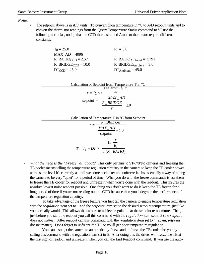
Notes: • The setpoint above is in A/D units. To convert from temperature in °C to A/D setpoint units and to
convert the thermistor readings from the Query Temperature Status command to °C use the following formulas, noting that the CCD thermistor and Ambient thermistor require different constants:
T0 = 25.0 R0 = 3.0 MAX_AD = 4096 R_RATIOCCD = 2.57 R_RATIOAmbient = 7.791 R_BRIDGECCD = 10.0 R_BRIDGEAmbient = 3.0 DTCCD = 25.0 DTAmbient = 45.0
Calculation of Setpoint from Temperature T in °C
r = R0 × eln( R _RATIO )×(T0 −T)
DT
setpoint =
MAX_ ADR_ BRIDGE
r+ 1.0
Calculation of Temperature T in °C from Setpoint
r =R_ BRIDGE
MAX _ADsetpoint
− 1.0
T = T0 − DT ×ln
rR0
ln(R_ RATIO)
• What the heck is the "Freeze" all about? This only pertains to ST-7/8/etc cameras and freezing the
TE cooler means telling the temperature regulation circuitry in the camera to keep the TE cooler power at the same level it's currently at until we come back later and unfreeze it. It's essentially a way of telling the camera to be very "quiet" for a period of time. What you do with the freeze commands is use them to freeze the TE cooler for readout and unfreeze it when you're done with the readout. This insures the absolute lowest noise readout possible. One thing you don't want to do is keep the TE frozen for a long period of time if you're not reading out the CCD because then you'll degrade the performance of the temperature regulation circuitry. To take advantage of the freeze feature you first tell the camera to enable temperature regulation with the regulation item set to 1 and the setpoint item set to the desired setpoint temperature, just like you normally would. This allows the camera to achieve regulation at the setpoint temperature. Then, just before you start the readout you call this command with the regulation item set to 3 (the setpoint does not matter). After readout call this command with the regulation item set to 4 (again, setpoint doesn't matter). Don't forget to unfreeze the TE or you'll get poor temperature regulation. You can also get the camera to automatically freeze and unfreeze the TE cooler for you by calling this command with the regulation item set to 5. After doing this the driver will freeze the TE at the first sign of readout and unfreeze it when you call the End Readout command. If you use the auto-
Santa Barbara Instrument Group Universal Driver Application Note
Page 17
freeze feature don't forget that call to End Readout. Finally to disable the auto-freeze function call this command with the regulation item set to 6. Finally, you can query whether the TE is frozen by logically anding the enabled item of Query Temperature Status command results with the REGULATION_FROZEN_MASK from the SBIGUDRV.H header. If it's set the TE is currently frozen (either manually or by the auto-freeze feature).
• The cooling in the ST-L’s Remote Guiding Head mimics the internal cooling. While the Remote Guiding Head has unregulated cooling the cooling is enable whenever internal TE power is above 0%.
3.3.2 Query Temperature Status The Query Temperature Status command is used to monitor the CCD's temperature regulation. The original version of this command took no Parameters (a NULL pointer) but the command has been expanded to allow a more user friendly result. If you pass a NULL pointer in the Parameters variable you’ll get the classic result. If you pass a pointer to a QueryTemperatureStatusParams struct you’ll have access to the expanded results.
Parameters Struct: struct SetTemperatureRegulationParams {
enum request – (see the TEMP_STATUS_REQUEST enum) } Standard Results Struct (request = TEMP_STATUS_STANDARD): struct QueryTemperatureStatusResults {
LOGICAL enabled - temperature regulation is enabled when this is TRUE ushort ccdSetpoint - CCD temperature or thermistor setpoint in A/D units ushort power - this is the power being applied to the TE cooler to maintain temperature regulation and
is in the range 0 thru 255 ushort ccdThermistor - this is the CCD thermistor reading in A/D units ushort ambientThermistor - this is the ambient thermistor reading in A/D units
} Standard Results Struct (request = TEMP_STATUS_ADVANCED): struct QueryTemperatureStatusResults2 {
LOGICAL coolingEnabled - temperature regulation is enabled when this is TRUE LOGICAL fanEnabled - fan is enabled when this is TRUE
double ccdSetpoint – CCD Setpoint temperature in °C double imagingCCDTemperature – imaging CCD temperature in degrees °C double trackingCCDTemperature – tracking CCD temperature in degrees °C double externalTrackingCCDTemperature – external tracking CCD temperature in °C double ambientTemperature – ambient camera temperature in °C double imagingCCDPower – percent power applied to the imaging CCD TE cooler double trackingCCDPower – percent power applied to the tracking CCD TE cooler double externalTrackingCCDPower – percent power applied to the external tracking TE cooler double heatsinkTemperature – imaging CCD heatsink temperature in °C double fanPower – percent power applied to the fan }
Notes:
Santa Barbara Instrument Group Universal Driver Application Note
Page 18
• Refer to the Set Temperature Regulation command for the formula to convert between A/D units and degrees C for the thermistor readings in the QueryTemperatureStatusResults. The advanced results report temperatures directly in Degrees C and need no conversion.
• You can query whether the TE is frozen (see the Set Temperature Regulation command) by logically anding the enabled item of the results with the REGULATION_FROZEN_MASK from the SBIGUDRV.H header. If it's set the TE is frozen.
3.4 External Control Commands The commands in this section are used to control the telescope position through the telescope interface or to position the CFW-6A motorized color filter wheel.
3.4.1 Activate Relay The Activate Relay command is used to activate one or more of the telescope control outputs or to cancel an activation in progress.
Parameters Struct: struct ActivateRelayParams {
ushort tXPlus - x plus activation duration in hundredths of a second ushort tXMinus - x minus activation duration in hundredths of a second ushort tYPlus - y plus activation duration in hundredths of a second ushort tYMinus - y minus activation duration in hundredths of a second
}
The status for this command (from the Query Command Status Command) consists of the following four bit field:
b3 = +X Relay, 0=Off, 1= Active b2 = -X Relay, 0=Off, 1= Active b1 = +Y Relay, 0=Off, 1= Active b0 = -Y Relay, 0=Off, 1= Active
Notes: • This command can be used to cancel relay activations by setting the appropriate parameters to 0.
3.4.2 Pulse Out The Pulse Out command is used with the ST-7/8/etc to position the CFW-6A/CFW-8 and with the PixCel255 and PixCel237 to position the internal vane/filter wheel.
Parameters Struct: struct PulseOutParams {
ushort numberPulses - number of pulses to generate (0 thru 255) ushort pulseWidth - width of pulses in units of microseconds with a minimum of 9 microseconds ushort pulsePeriod - period of pulses in units of microseconds with a minimum of 29 plus the
pulseWidth microseconds } The status for this command (from the Query Command Status command) consists of the following bit fields:
b0 - Normal status, 0 = inactive, 1 = pulse out in progress
Santa Barbara Instrument Group Universal Driver Application Note
Page 19
b1-b3 - PixCel255/237 Filter state, 0=moving, 1-5=at position 1-5, 6=unknown Notes:
• The camera will cease communications while the Pulse Out command is in progress to maintain the best pulse width accuracy. After sending the ACK response the camera will generate the pulses and only when it has finished generating the pulses will it respond to further communications from the PC.
• With the PixCel255/237 for positioning the internal vane/filter wheel you set the numberPulses parameter to a non-zero value (typically 1), the pulseWidth to zero and the pulsePeriod to one of the following values: 0=Leave vane/filter alone, 1-5=Position vane/filter wheel at position 1 thru 5, 6=Stop motor, abort any move in progress, 7=initialize and identify vane/filter wheel.
• On the PixCel255/237 the following filter positions are defined: Position 1 = Clear/Open, Position 2 = Opaque, Position 3 = Red, Position 4 = Green and Position 5 = Blue. Positions 1 and 2 are supported by the vane and positions 1 thru 5 are supported by the filter wheel.
• You find out what type of filter wheel is installed in the PixCel255/237 using the Get CCD Info command with request number 3.
• See the CFW command below for a high level API for programming the SBIG color filter wheels. • The Pulse Out command directed to an ST-L will cause the ST-L’s CFW-L to emulate a CFW-8.
This makes old software for the CFW-8 work on the CFW-L but new code should use the CFW command to support the CFW-L.
3.4.4 TX Serial Bytes The TX Serial Bytes command is for internal use by SBIG. It’s a very low level version of commands like AO Tip Tilt that are used to send data out the ST-7/8/etc’s telescope port to accessories like the AO-7. There’s no reason why you should need to use this command. Just use the dedicated commands like AO Tip Tilt.
3.4.5 Get Serial Status The Get Serial Status command is for internal use by SBIG. It’s a very low level version of commands like AO Tip Tilt that are used to send data out the ST-7/8/etc’s telescope port to accessories like the AO-7. There’s no reason why you should need to use this command. Just use the dedicated commands like AO Tip Tilt.
3.4.6 AO Tip Tilt The AO Tip Tilt Command is used to position an AO-7 attached to the telescope port of an ST-7/8/etc.
Parameters Struct: struct AOTipTiltParams {
ushort xDeflection - this is the desired position of the mirror in the X axis ushort yDeflection - this is the desired position of the mirror in the Y axis
} Notes:
• The range for the X and Y deflection parameters are 0 through 4095. The mirror is centered at 2048, fully to one side at 0 and fully at the other side with 4095.
• While commanding the AOL to position 2048, 2048 will take it to the center of its range, using the AO Center command described below will force the AOL to re-find center using the mechanical home positioning sensors.

Santa Barbara Instrument Group Universal Driver Application Note
Page 20
3.4.7 AO Center This command centers the AO attached to the camera. It takes no Parameters or Results structs and returns an error code. This works with the AO-7 and the AOL but in the case of the AOL this causes the unit to find the center using the mechanical home sensors.
3.4.8 AO Set Focus This command is reserved for future use with motorized focus units. Prototypes of the AO-7 had motorized focus but the feature was removed in the production units. This command is a holdover from that.
3.4.9 AO Delay The AO Delay Command is used to generate millisecond type delays for exposing the Tracking CCD.
Parameters Struct: struct AODelayParams {
ulong delay - this is the desired delay in microseconds } Notes:
• The computer essentially hangs while waiting for this delay to expire so be careful how you use this command.
3.4.10 CFW The CFW Command is a high-level API for controlling the SBIG color filter wheels. It supports the CFW-2 (two position shutter wheel in the ST-5C/237), the CFW-5 (internal color filter wheel for the ST-5C/237), the CFW-8, the internal filter wheel (CFW-L) in the ST-L Large Format Camera, the internal filter wheel (CFW-402) in the ST-402 camera, the old 6-position CFW-6A, the 10-position CFW-10 in both I2C and RS-232 interface modes and the new I2C based CFW-9 and 8-position CFW for the STL (CFW-L8).
Parameters Struct: struct CFWParams {
enum cfwModel – (see the CFW_MODEL_SELECT enum) 0=Unknown, 1=CFW-2, 2=CFW-5, 3=CFW-8, 4=CFW-L, 5=CFW-402, 6=Auto detect, 7=CFW-6A, 8=CFW-10, 9=RS232 based CFW-10, 10=CFW-9, 11=Standard CFW-L8, 10=Custom CFW-L8
enum cfwCommand – (see the CFW_COMMAND enum) . 0=Query, 1=Goto, 2=Init, 3=Get Info, 4=Open CFW Device, 5=Close CFW Device ulong cwfParam1 – command specific ulong cfwParam2 – “ “ ushort outLength – “ “ uchar *outPtr – “ “ ushort inLength – “ “ uchar *inPtr – “ “ } Results Struct: typedef struct CFWResults {
Santa Barbara Instrument Group Universal Driver Application Note
Page 21
ushort cfwModel – See cfwModel above ushort cfwPosition – (see the CFW_POSITION enum) 0=Unknown, 1 thru 10 = Position 1 thru 10 ushort cfwStatus – (see the CFW_STATUS enum) 0=Unknown, 1=Idle, 2= Busy ushort cfwError – (see the CFW_ERROR enum) 0=No Error, 1=CFW Busy, 2=Bad Command, 3=Calibration Error, 4 = Motor Timeout, 5=Bad Model ulong cfwResult1 – command specific ulong cfwResult2 – “ “ } CFW Command CFWC_QUERY
• Use this command to monitor the progress of the Goto sub-command. This command takes no additional parameters in the CFParams. You would typically do this several times a second after the issuing the Goto command until it reports CFWS_IDLE in the cfwStatus entry of the CFWResults. Additionally filter wheels that can report their current position (all filter wheels except the CFW-6A or CFW-8) have that position reported in cfwPosition entry of the CFWResults.
CFW Command CFWC_GOTO
• Use this command to start moving the color filter wheel towards a given position. Set the desired position in the cfwParam1 entry with entries defined by the CFW_POSITION enum.
CFW Command CFWC_INIT
• Use this command to initialize/self-calibrate the color filter wheel. All SBIG color filter wheels self calibrate on power-up and should not require further initialization. We offer this option for users that experience difficulties with their color filter wheels or when changing between the CFW-2 and CFW-5 in the ST-5C/237. This command takes no additional parameters in the CFWParams struct.
CFW Command CFWC_GET_INFO
• This command supports several sub-commands as determined by the cfwParam1 entry (see the CFW_GETINFO_SELECT enum). Command CFWG_FIRMWARE_VERSION returns the version of the CFW firmware in the cfwResults1 entry of the CFWResults and the number of filter positions the CFW supports in the cfwResults2 entry , commands CFWG_DATA_REGISTERS and CFWG_CAL_DATA are for internal SBIG use only and all other commands are undefined.
CFW Commands CFWC_OPEN_DEVICE and CFWC_CLOSE_DEVICE
• These commands are used to Open and Close any OS based communications port associated with the CFW and should proceed the first command sent and follow the last command sent to the CFW. While strictly only required for the RS-232 version of the CFW-10 calling these commands is a good idea for future compatibility. For the RS-232 based CFW-10 set the cfwParam1 entry to one of the settings from the CFW_COM_PORT enum to indicate which PC COM port is used to control the CFW-10. Again, only the RS232 controlled CFW-10 requires these calls.
Notes:
• The CFW Command takes pointers to CFWParams as parameters and CFWResults as results.
Santa Barbara Instrument Group Universal Driver Application Note
Page 22
• Set the cfwModel entry in the CFWParams to the type of filter wheel you want to control. The same value is returned in the cfwModel entry of the CFWResults. If you select the CFWSEL_AUTO option the driver will use the most appropriate model.
• The CFW Command is a single API call that supports multiple sub-commands through the cfwCommand entry in the CFWParams. Each of the sub-commands requires certain settings of the CFWParams entries and returns varying results in the CFWResults. Each of these sub-commands is discussed in detail above.
• As with all API calls the CFW Command returns an error code. If the error code is CE_CFW_ERROR, then in addition the cfwError entry in the CFWResults further enumerates the error.
• With the CFW-6A model color filter wheel set the cfwParam1 item to the desired calibrated pulse width in microseconds for the Goto and Init sub-commands.
3.4.11 Motor Focus The Motor Focus Command is a high-level API for controlling SBIG Motor Focus accessories. It supports the new ST Motor Focus unit and will be expanded as required to support new models in the future.
Parameters Struct: struct MFParams{ enum mfModel – (see the MF_MODEL_SELECT enum) 0=Unknown, 1=Auto Select, 2=ST Motor Focuser enum mfCommand – (see the MF_COMMAND enum) 0=Query, 1=Goto, 2=Init, 3=Get Info, 4=Abort long mfParam1 - command specific long mfParam2 - “ “ ushort outLength - “ “ uchar *outPtr - “ “ ushort inLength - “ “ uchar *inPtr - “ “ } MFParams; Results Struct: typedef struct { enum mfModel - (see the mfModel above) long mfPosition – (position of the Motor Focus, 0=Center, signed) enum mfStatus – (see the MF_STATUS enum) enum mfError – (see the MF_ERROR enum) long mfResult1 – command specific long mfResult2 – “ “ } MFResults; Motor Focus Command MFC_QUERY
• Use this command to monitor the progress of the Goto sub-command. This command takes no additional parameters in the MFParams. You would typically do this several times a second after the issuing the Goto command until it reports MFS_IDLE in the mfStatus entry of the MFResults. Motor Focus accessories report their current position in the mfPosition entry of the MFResults struct where the position is a signed long with 0 designating the center of motion or the home position. Also the Temperature in hundredths of a degree-C is reported in the mfResult1 entry.
Santa Barbara Instrument Group Universal Driver Application Note
Page 23
Motor Focus Command MFC_GOTO
• Use this command to start moving the Motor Focus accessory towards a given position. Set the desired position in the mfParam1 entry. Again, the position is a signed long with 0 representing the center or home position.
Motor Focus Command MFC_INIT
• Use this command to initialize/self-calibrate the Motor Focus accessory. This causes the Motor Focus accessory to find the center or Home position. You can not count on SBIG Motor Focus accessories to self calibrate upon power-up and should issue this command upon first establishing a link to the Camera. Additionally you should retain the last position of the Motor Focus accessory in a parameter file and after initializing the Motor Focus accessory, you should return it to its last position. Finally, note that this command takes no additional parameters in the MFParams struct.
Motor Focus Command MFC_GET_INFO
• This command supports several sub-commands as determined by the mfParam1 entry (see the MF_GETINFO_SELECT enum). Command MFG_FIRMWARE_VERSION returns the version of the Motor Focus firmware in the mfResults1 entry of the MFResults and the Maximum Extension (plus or minus) that the Motor Focus supports is in the mfResults2 entry. The MFG_DATA_REGISTERS command is internal SBIG use only and all other commands are undefined.
Motor Focus Command MFC_ABORT
• Use this command to abort a move in progress from a previous Goto command. Note that this will not abort an Init.
Notes:
• The Motor Focus Command takes pointers to MFParams as parameters and MFResults as results. • Set the mfModel entry in the MFParams to the type of Motor Focus accessory you want to control.
The same value is returned in the mfModel entry of the MFResults. If you select the MFSEL_AUTO option the driver will use the most appropriate model and return the model it found in the mfModel entry of the MFResults.
• The Motor Focus Command is a single API call that supports multiple sub-commands through the mfCommand entry in the MFParams. Each of the sub-commands requires certain settings of the MFParams entries and returns varying results in the MFResults. Each of these sub-commands is discussed in detail above.
• As with all API calls the Motor Focus Command returns an error code. If the error code is CE_MF_ERROR, then in addition the mfError entry in the MFResults further enumerates the error.
3.5 General Purpose Commands The commands discussed in this section are general-purpose commands that do not fall into one of the groups discussed above. They are used by the application to interrogate the driver and camera.
3.5.1 Establish Link The Establish Link command is used by the application to establish a communications link with the camera. It should be used before any other commands are issued to the camera (excluding the Get Driver Info command).
Parameters Struct: struct EstablishLinkParams {
Santa Barbara Instrument Group Universal Driver Application Note
Page 24
ushort sbigUseOnly – leave set to 0, maintained for historical purposes only }
Results Struct: struct EstablishLinkResults {
enum cameraType - constant specifying the type of camera as specified by the CAMERA_TYPE enum
} Notes:
• The EstablishLinkParams struct was modified in version 4 of the driver and no longer specifies the LPT base address. This data is now supplied to the driver through the Open Device command.
• When establishing a link to an ST-237A the cameraType is reported as an original ST237_CAMERA. This was done for maximum compatibility with existing 3rd party software packages. The way you distinguish an ST-237A (16 bit A/D) from the ST-237 (12 bit A/D) is by checking the gain item from the Get CCD Info command response. If the gain is less than 1.0 (0x100) you are talking to an ST-237A.
3.5.2 Get CCD Info The Get CCD Info command is used by the application to determine the model of camera being controlled and its capabilities. For future expandability this command allows you to request several types of information. Currently 6 standard requests are supported but as the driver evolves additional requests will be added.
Parameters Struct: struct GetCCDInfoParams {
enum request - type of CCD information desired (see the CCD_INFO_REQUEST enum) 0 = standard request for Imaging CCD
1 = standard request for Tracking CCD 2 = extended request for Camera Info 3 = extended request for PixCel255/237 Camera Info 4 = secondary extended request for Imaging CCD 5 = secondary extended request for Tracking CCD 6,7, etc. - reserved for future expansion
}
Standard Results Struct : requests 0 and 1 - struct GetCCDInfoResults0 {
ushort firmwareVersion - version of the firmware in the resident microcontroller in BCD format (XX.XX, 0x1234 = 12.34)
enum cameraType - constant specifying the type of camera, (see CAMERA_TYPE enum in SBIGUDRV.H)
char name[64] - null terminated string containing the name of the camera ushort readoutModes - number of readout modes supported struct readoutInfo[20] {
ushort mode - readout mode to pass to the Readout Line command ushort width - width of image in pixels ushort height - height of image in pixels ushort gain - a four digit BCD number specifying the amplifier gain in e-/ADU in the XX.XX
format.
Santa Barbara Instrument Group Universal Driver Application Note
Page 25
ulong pixelWidth - an eight digit BCD number specifying the pixel width in microns in the XXXXXX.XX format.
ulong pixelHeight - an eight digit BCD number specifying the pixel height in microns in the XXXXXX.XX format.
} } request 2 - struct GetCCDInfoResults2 { ushort badColumns - number of bad columns in imaging CCD ushort columns[4] - bad columns enum imagingABG - type of Imaging CCD, 0= No ABG Protection, 1 = ABG Present char serialNumber[10] - null terminated serial number string } request 3 - For the PixCel255/237 struct GetCCDInfoResults3 { enum adSize - 0 = Unknown, 1 = 12 bits, 2 = 16 bits enum FilterType - 0 = Unknown, 1 = External, 2 = 2 Position, 3 = 5 Position } requests 4 and 5 - For all cameras struct GetCCDInfoResults4 {
ushort capabilitiesBits – Set of bits for additional capabilities: b0: 0 = CCD is Full Frame Device, 1 = CCD is Frame Transfer Device, b1: 0 = No Electronic Shutter, 1 = Interline Imaging CCD with Electronic Shutter and
millisecond exposure capability b2: 0 = No hardware support for external Remote Guide Head, 1 = Detected hardware
support for external Remote Guide Head. ushort dumpExtra – Number of unbinned rows to dump to transfer image area to storage area } Notes:
• The ST-7/8/etc supports types 0, 1, 2, 4 and 5 requests. The PixCel255/237 supports request types 0, 3, 4 and 5.
• A zero in the height field of the readoutInfo struct signifies the xN mode vertically. • Mode 9 with 9x9 binning on some sensors (like the ST-1K) will report the maximum pixel height/width
of 99.99 even though the binned pixels are actually larger. If you need the correct pixel size multiply the pixel size from mode 0 by the binning factor.
• Requests 4 and 5 are for use when you bypass the Start Exposure/End Exposure commands for reading out the CCD such as when you are doing millisecond type exposures with the Tracking CCD and an AO-7. Normally the End Exposure command handles transferring the imaging area and dummy rows of these CCDs to the storage area but when you bypass it you must provide for that transfer by adding the number specified in the dumpExtra field to the amount of lines you want to discard with the Dump Lines command. If you don’t supplement the number of lines to dump you will be digitizing data from the storage area of the CCD and won’t see any star images at all.
Santa Barbara Instrument Group Universal Driver Application Note
Page 26
• Request 5 will indicate whether the camera supports the external Remote Guide Head. • See the notes for the Establish Link command above. • There are several sub-models of the ST-L based upon the type of CCD they contain but they all report
the same value in the cameraType field (STL_CAMERA) of request 0. The name field includes the sub-model.
• Single Shot Color cameras like the ST-2000XCM will have “Color” in the name item. You can use this to decide whether you want to interpret the color information or not.
3.5.3 Get Turbo Status The current driver does not use this command. It was added in a previous version and never removed. It could be reassigned in the future.
3.5.4 Query Command Status The Query Command Status command is used to monitor the progress of a previously requested command. Typically this will be used to monitor the progress of an exposure, relay closure or CFW-6A move command.
Parameters Struct: struct QueryCommandStatusParams {
ushort command - command of which the status is desired }
Results Struct: struct QueryCommandStatusResults {
ushort status - command status }
3.5.5 Miscellaneous Control The Miscellaneous Control command is used to control the Fan, LED, and shutter. The camera powers up with the Fan on, the LED on solid, and the shutter closed. The driver flashes the LED at the low rate while the Imaging CCD is integrating, flashes the LED at the high rate while the Tracking CCD is integrating and sets it on solid during the readout.
Parameters Struct: struct MiscellaneousControlParams {
LOGICAL fanEnable - set TRUE to turn on the Fan enum shutterCommand – (see the SHUTTER_COMMAND enum)
0=leave shutter alone, 1=open shutter, 2=close shutter, 3=reinitialize shutter, 4=open ST-L external shutter, 5=close ST-L external shutter
enum ledState – (see the LED_STATE enum) 0=LED off, 1=LED on, 2=LED blink at low rate, 3=LED blink at high rate
}
The status for this command (from the Query Command Status Command) consists of the following bit fields: b7-b0 - Shutter edge - This is the position the edge of the shutter was detected at for the last
shutter move. Normal values are 7 thru 9. Any other value including 255 indicates a shutter failure and the shutter should be reinitialized.
b8 - the Fan is enabled when this bit is 1 b10b9 - Shutter state, 0=open, 1=closed, 2=opening, 3=closing

Santa Barbara Instrument Group Universal Driver Application Note
Page 27
b12b11 - LED state, 0=off, 1=on, 2=blink low, 3=blink high Notes:
• The ST-7/8/etc have a shutter, LED and fan but no filter wheel. To position the CFW-6/8 attached to these cameras use the Pulse Out command.
• The PixCel255 has no shutter, fan control or LED but does have a vane/filter wheel. The settings of the fanEnabled, shutterCommand and ledState parameters are ignored and should be set to 0.
• The PixCel237 has no shutter or LED but does have a fan that can be controlled (turned on and off) and vane/filter wheel. The settings of the shutterCommand and ledState parameters are ignored and should be set to 0. The fanEnable is used to control the fan.
• The ST-7/8/etc will cease communications with the PC while the reinitialize shutter command is in progress. After the driver tells the camera to reinitialize the shutter the driver delays 3 seconds for the process to complete.
• For this command the ST-l’s external shutter DOES NOT mimic the internal shutter (like it does with the Start Exposure command). To control the ST-L’s external shutter in the Remote Tracking Head pass to shutterCommand the SC_OPEN_EXT_SHUTTER and SC_CLOSE_EXT_SHUTTER values.
3.5.6 Update Clock The Update Clock no longer supported and calls to this command will do nothing. On older Windows 95/98/Me based systems run or spawn the SETCLOCK.EXE program to restore the system clock for lost time during the readout of parallel port based cameras. Other Windows versions or systems using USB cameras don’t loose time.
3.5.7 Read Offset The Read Offset command is used to measure the CCD's offset. In the SBIG cameras the offset is adjusted at the factory and this command is for testing or informational purposes only.
Parameters Struct: struct ReadOffsetParams {
enum ccd - the CCD to measure offset (see the CCD_REQUEST enum) 0 = Imaging CCD 1 = Tracking CCD 2 = External Tracking CCD in ST-L
}
Results Struct: struct ReadOffsetResults {
ushort offset - the CCD's offset }
3.5.8 Get US Timer This command is of extremely limited (and unknown) use. When you have established a link to a parallel port based camera under Windows NT/2000/XP this command returns a counter with 1 microsecond resolution. Under all other circumstances the counter is zero.
3.5.9 Set/Get IRQL This command allows you to control the IRQ priority of the driver under Windows NT/2000/XP. The default settings should work fine for all users and these commands should not need to be used.

Santa Barbara Instrument Group Universal Driver Application Note
Page 28
We use three settings in our CCDOPS software: High = 27, Medium = 15, Low = 2. Under fast machines Low will work fine. On slower machines the mouse may get sluggish unless you select the Medium or High priority.
3.5.10 Get Link Status This command returns the status of the communications link established with the camera. Results Struct: struct {
LOGICAL linkEstablished – TRUE when a link has been established ushort baseAddress – base address of the LPT port ushort cameraType – CAMERA_TYPE enum ulong comTotal – total number of communications with camera ulong comFailed – total number of failed communications with camera
}
3.5.11 Get Error String This command returns a null terminated C string in English (not Unicode) corresponding to the passed error number. It’s handy for reporting driver level errors to the user.
3.5.12 Set Driver Control This command is used to modify the behavior of the driver by changing the settings of one of the driver control parameters. Driver options can be enabled or disabled with this command.
Parameters Struct: struct SetDriverControlParams {
enum controlParameter - the parameter to modify (see the DRIVER_CONTROL_PARAM enum)
long controlValue – the value of the control parameter } Notes:
• The DCP_USB_FIFO_ENABLE parameter defaults to TRUE and can be set FALSE to disable the FIFO and associated pipelining in the USB cameras. You would do this for example in applications using Time Delay Integration (TDI) where you don’t want data in the CCD digitized until the actual call to ReadoutLine is made.
• The DCP_CALL_JOURNAL_ENABLE parameter defaults to FALSE and can be set to TRUE to have the driver broadcast Driver API calls. These broadcasts are handy as a debug tool for monitoring the sequence of API calls made to the driver. The broadcasts can be received and displayed with the Windows based SBIGUDRVJournalRx.exe application. Only use this for testing purposes and do not enabled this feature in your released version of you application as the journaling mechanism can introduce minor artifacts in the readout.
• The DCP_IVTOH_RATIO parameter sets the number of Vertical Rows that are dumped (fast) before the Horizontal Register is dumped (not as fast) in the DumpRows command for Parallel Port based cameras. This is a very specialized parameter and you should think hard about changing it if you do. The default of 5 for the IHTOV_RATIO has been determined to offer a good compromise between the time it takes to clear the CCD or Dump Rows and the ability to effectively clear the CCD after imaging

Santa Barbara Instrument Group Universal Driver Application Note
Page 29
a bright object. Finally should you find it necessary to change it read the current setting and restore it when you’re done.
• The DCP_USB_FIFO_SIZE parameter sets the size of the FIFO used to receive data from USB cameras. The default and maximum value of 16384 yields the highest download speeds. Lowering the value will cause the camera to digitize and download pixels in smaller chunks. Again this is a specialized parameter that 99.9% of programs out there will have no need for changing.
• The DCP_USB_PIXEL_DL_ENABLE parameter allows disabling the actual downloading of pixel data from the camera for testing purposes. This parameter defaults to TRUE.
• The DCP_HIGH_THROUGHPUT parameter allows configuring the driver for the highest possible imaging throughput at the expense of image noise and or artifacts. This parameter defaults to FALSE and you should only enable this for short periods of time. You might use this in Focus mode for example to get higher image throughput but you should never use it when you are taking keeper images. It does things that avoid timed delays in the camera like leaving the shutter motor on all the time, not lowering the amplifier bias, etc. At this time this feature is supported in the driver but not all cameras show a benefit from its use.
• The DCP_VDD_OPTIMIZED parameter defaults to TRUE which lowers the CCD’s Vdd (which reduces amplifier glow) only for images 3 seconds and longer. This was done to increase the image throughput for short exposures as raising and lowering Vdd takes 100s of milliseconds. The lowering and subsequent raising of Vdd delays the image readout slightly which causes short exposures to have a different bias structure than long exposures. Setting this parameter to FALSE stops the short exposure optimization from occurring.
• The DCP_AUTO_AD_GAIN parameter defaults to TRUE whereby the driver is responsible for setting the A/D gain in USB cameras. Setting this to FALSE allows overriding the driver imposed A/D gains.
Notes:
• As of 9/9/03 there is one set of parameters for the whole DLL vs. one per handle.
3.5.13 Get Driver Control This command is used to query the setting of one of the driver control parameters. Parameters Struct: struct GetDriverControlParams {
enum controlParameter - the parameter to modify (see the DRIVER_CONTROL_PARAM enum)
}
Results Struct: struct GetDriverControlResults {
long controlValue – the value of the control parameter } Notes:
• See the Set Driver Control command above.
3.5.14 USB AD Control This command is used to modify the USB cameras A/D gain and offset registers.
Santa Barbara Instrument Group Universal Driver Application Note
Page 30
Parameters Struct: struct USBADControlParams {
enum command – Imaging or Tracking CCD Gain or Offset (see the USB_AD_CONTROL_COMMAND enum)
short data – command specific } Notes:
• This command is intended for OEM use only. The typical application does not need to use this command as the USB cameras initialize the A/D to factory set defaults when the camera powers up.
• For the USB_AD_IMAGING_GAIN and AD_USB_TRACKING_GAIN commands the allowed setting for the data parameter is 0 through 63. The actual Gain of the A/D (in Volts/Volt) ranges from 1.0 to 6.0 and is determined by the following formula:
Gain = 6.0 / ( 1.0 + 5.0 * ( (63 – data) / 63 )
Note that the default A/D Gain set by the camera at power up is 1.2 for the Imaging CCD and 2.0 for the Tracking CCD. Furthermore, the gain item reported by the Get CCD Info command will always report the default factory-set gain and will not change based upon changes made to the A/D gain by this command.
• For the USB_AD_IMAGING_OFFSET and USB_AD_TRACKING_OFFSET commands the allowed setting for the data parameter is –255 through 255. Positive offsets increase the video black level in ADUs. The cameras are programmed at the factory to typically have a 900 to 1000 ADU black level offset.
3.5.15 Query USB This command is used to query the USB bus and detect up to four cameras. This allows the user to have multiple USB cameras and for the programmer to connect with specific cameras. This command takes no parameters and returns data for up to four cameras.
Results Struct: typedef struct { unsigned short camerasFound – total number of cameras found, 0 through 4 struct QUERY_USB_INFO usbInfo[4] – data for up to 4 cameras
MY_LOGICAL cameraFound – TRUE if camera found enum CAMERA_TYPE cameraType – type of camera found char name[64] – name of camera (like from GetCCDInfo command) char serialNumber[10] – camera’s serial number (like from GetCCDInfo command)
} QueryUSBResults; Notes:
• To Establish a link to a specific camera specify DEV_USB1, DEV_USB2, DEV_USB3 or DEV_USB4 in the device field of the Open Device command. DEV_USB1 corresponds to the camera described in usbInfo[0], DEV_USB2 corresponds to usbInfo[1], etc. If you specify USB_DEV in Open Device it opens the next available device.
• You should call this command after calling Open Driver but before calling Open Device.
Santa Barbara Instrument Group Universal Driver Application Note
Page 31
3.5.16 Query Ethernet This command is used to query and detect up to four cameras Ethernet based cameras. This allows the user to have multiple Ethernet cameras and for the programmer to connect with specific cameras. This command takes no parameters and returns data for up to four cameras.
Results Struct: typedef struct { unsigned short camerasFound – total number of cameras found, 0 through 4 struct QUERY_ETHERNET_INFO ethernetInfo[4] – data for up to 4 cameras
MY_LOGICAL cameraFound – TRUE if camera found ulong ipAddress – IP address of camera enum CAMERA_TYPE cameraType – type of camera found char name[64] – name of camera (like from GetCCDInfo command) char serialNumber[10] – camera’s serial number (like from GetCCDInfo command)
} QueryEthernetResults; Notes:
• To establish a link to a specific camera specify the discovered IP Address in the IP Address field of the Open Device command.
• You should call this command after calling Open Driver but before calling Open Device.
3.5.17 Get Pentium Cycle Count This command is used to read a Pentium processor’s internal cycle counter. Pentium processors have a 32 or 64 bit register that increments every clock cycle. For example on a 1 GHz Pentium the counter advances 1 billion counts per second. This command can be used to retrieve that counter.
Parameters Struct: typedef struct {
short rightShift – number of bits to shift the results to the right (dividing by 2) } GetPentiumCycleCountParams; Results Struct: typedef struct { unsigned long countLow – lower 32 bits of the Pentium cycle counter unsigned long countHigh – upper 32 bits of the Pentium cycle counter } GetPentiumCycleCountResults; Notes:
• Only call this function if you are sure your code is running on a Pentium processor. • As the Pentium counter increments every clock cycle and the rate depends on the CPU clock rate, if
you want to use this command for generating precise delays you’ll need to calibrate the counter over a period of time like 1 or 10 seconds.
• As the Pentium clock rates ate quite high (typically hundreds of Megahertz or higher) this counter has much higher resolution than most programs need. Furthermore the 64-bit result can be cumbersome. Setting the rightShift item in the parameters allows reducing the resolution. For example on a 1 GHz Pentium setting the rightShift to 10 divides the results by 210 or 1024 returning a good approximation to a 1 microsecond timer that overflows the countLow only once every 4295 seconds.
Santa Barbara Instrument Group Universal Driver Application Note
Page 32
3.5.18 RW USB I2C This command is used read or write data to the USB cameras I2C expansion port.
Parameters Struct: typedef struct { unsigned char address – Address to read from or write to unsigned char data – Data to write to the external I2C device, ignored for read MY_LOGICAL write – TRUE when write is desired , FALSE when read is desired unsigned char deviceAddress – Device Address of the I2C peripheral } RWUSBI2CParams; Results Struct: typedef struct { unsigned char data – Data read from the external I2C device } RWUSBI2CResults; Notes:
• This command is typically called by SBIG code in the Universal Driver. If you think you have some reason to call this function you should check with SBIG first.
3.5.18 Bit IO This command is used read or write control bits in the USB cameras.
Parameters Struct: typedef struct { unsigned short bitOperation – 0=Write, 1=Read
unsigned short bitName – 0=Read Power Supply Low Voltage, 1=Write Genl. Purp. Bit 1, 2=Write Genl. Purp. Bit 2, 3=Read Genl. Purp. Bit 3
MY_LOGICAL setBit - 1=Set Bit, 0=Clear Bit } BitIOParams; Results Struct: typedef struct { MY_LOGICAL bitIsSet - 1=Bit is set, 0=Bit is clear } BitIOResults; Notes:
• On the ST-L camera you can use this command to monitor whether the input power supply has dropped to the point where you ought to warn the user. Do this by issuing a Read operation on bit 0 and if that bit is set the power has dropped below 10 Volts.
4. Windows Based Utility Programs This section describes several Windows based tool programs that SBIG provides to help you get your custom application up and running.
Santa Barbara Instrument Group Universal Driver Application Note
Page 33
4.1 SBIGDriverChecker.exe This program checks the drivers installed on the system against the “SBIG Driver” directory. It reports whether the drivers installed are current and allows you to download the latest drivers from SBIG’s Servers with the Download button then update all drivers with the Update button. Please read the “Installing USB.pdf” and note that you should distribute this program and the SBIG Drivers directory with your code so users can install the latest drivers. The latest version and the associated drivers can be downloaded from the Software Downloads page of our home pag. This utility needs to be run in Administrator mode on NT/2000/XP machines and depends on the SBIG Drivers directory being in the same directory as the utility. Also note that if you try to run this program from your installer and you get the error message “Could not find the SBIG Drivers” it’s because the Installer is not setting the current working directory to the utility directory. You can get around this if you pass this program a command line argument with the full path to the utility. For example if these items are installed into the “C:\Program Files\My Company\My Program” directory pass the SBIGDriverChecker.exe utility “C:\Program Files\My Company\My Program\SBIGDriverChecker.exe” without the quotes as the command line argument. The program usually requires user intervention to update the drivers, which we feel is the safest way to go. You can however pass the program the “/s” command line argument in which case it will run in “silent” mode and automatically update the drivers and then exit.
4.2 EthSim.exe The EthSim.exe tool allows you to simulate various model cameras on an Ethernet network. This is handy for testing your programs without a camera. To use EthSim do the following:
• Copy the EthSim.exe program and your Test Program to computers connected together through an Ethernet LAN. The two programs can run on two different computers or the same computer so long as that computer has Ethernet. You can use CCDOPS as the Test Program.
• Double-click the EthSim icon or run EthSim.exe from the command line. EthSim takes an optional command line parameter specifying the type of camera to simulate. For example, to simulate an ST-2K you would run:
ethsim 2K
with no command line parameter it defaults to an ST-7. • Select Ethernet for the Comm link and enter the IP address of the computer running EthSim.exe • Establish a link to the simulated camera
EthSim will generate random pixel data for both the Imaging and Tracking CCDs and simulates the following types of cameras:
ST-5C, ST-237, ST-237A, ST-7, ST-8, ST-9, ST-10, ST-1K, ST-2K, STL-11K and ST-402
4.3 SBIGUDRVJournalRx.exe The SBIGUDRVJournalRx.exe tool is used in conjunction with the DCP_CALL_JOURNAL_ENABLE Driver Control Parameter of the Set Driver Control command. When that parameter is set TRUE the driver broadcasts API calls. SBIGUDRVJournalRx.exe receives and displays those broadcasts. The broadcasts essentially tell you the sequence of API calls made to the driver. SBIGUDRVJournalRx has a scrolling window that shows the API call sequence. In addition the program has the following controls:
• Clear – Clicking this button clears the log window
Santa Barbara Instrument Group Universal Driver Application Note
Page 34
• Filters – Clicking this button brings up a dialog that allows you to filter out any or all of the API calls from the displayed log window.
• Show Log – Uncheck this button to disable the display of API calls • Send Msg – Clicking this button simulates a broadcast from the driver to the program using the
WParam and LParam data entry boxes. Each time you click this button a message should appear in the log.
Finally note that if you are not receiving API broadcasts messages from the driver it is probably because you did not enable journaling with the Set Driver Control command. Just for reference CCDOPS does not enable them.
4.4 SetClock.exe This 16-Bit windows program, which you can distribute with yoru Application if you find it useful, reads the CMOS clock on the PC and sets the Windows System time to that value. It can take up to 1 second to synchronize the clocks as it waits till the CMOS clock hits the second mark. Typically you would spawn this program at the end of the readout on a Parallel camera on Windows 95/98/Me based systems to adjust for the seconds lost while interrupts were disabled for the readout.
4.5 GetPortD.exe This 16-Bit DOS program is used to determine the I/O address of the LPT ports on Windows 95/98/Me based systems. It reads the LPT address information from DOS, displays the address of the three LPT ports and creates a binary file named PORTADDR.DAT containing those addresses. We uses this to allow the user to select “LPT1, LPT2 or LPT3” instead of the I/O address for the Parallel port. Spawn this program, then open and read three unsigned shorts from the PORTADDR.DAT file. The first is the I/O address of LPT1, the second LPT2 and the third LPT3. You then pass this information to the Open Device command.
5. Supporting New Cameras and Accessories This section gives specific instructions about how to support relatively new model cameras and accessories starting with the ST-L.
5.1 Supporting the ST-L The ST-L (Large Format Camera) is a USB 1.1 based camera much like the USB version of the ST-7/8/… with the following significant differences:
• There are several models of the ST-L with various imaging CCDs. These include the 11 Megapixel ST-L-11K with the Kodak KAI-11000 and various other models. While there is only a single cameraType (STL_CAMERA) returned by the Establish Link command, the Get CCD Info command returns the appropriate pixel information (pixel size and number of pixels) and the name includes the model type.
• The camera has an internal 5-position filter wheel referred to as the CFW-L. The carousel allows using 2-inch diameter filter substrates or filters mounted in 48mm cells. To support the CFW-L use the new CFW Command described in Section 2.4.9. Unlike the CFW-8, the CFW-L actually detects erroneous moves and reports those back via the CFW command. In addition the CFW-L is self-calibrating on power-up but can be recalibrated at any time with the CFW command.
• The ST-L firmware does not support generating pulses out the CFW port. The Universal Driver will redirect Pulse Out commands to the internal CFW-L making the CFW-L mimic a CFW-8. This allows CFW-8 software to work with the CFW-L but you really should add support for the CFW-L with the CFW command described in Section 2.4.9.
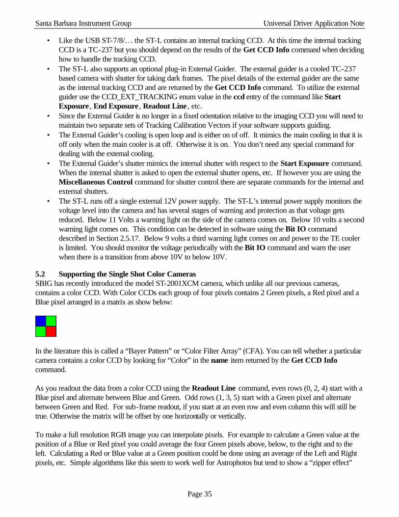
Santa Barbara Instrument Group Universal Driver Application Note
Page 35
• Like the USB ST-7/8/… the ST-L contains an internal tracking CCD. At this time the internal tracking CCD is a TC-237 but you should depend on the results of the Get CCD Info command when deciding how to handle the tracking CCD.
• The ST-L also supports an optional plug-in External Guider. The external guider is a cooled TC-237 based camera with shutter for taking dark frames. The pixel details of the external guider are the same as the internal tracking CCD and are returned by the Get CCD Info command. To utilize the external guider use the CCD_EXT_TRACKING enum value in the ccd entry of the command like Start Exposure , End Exposure , Readout Line , etc.
• Since the External Guider is no longer in a fixed orientation relative to the imaging CCD you will need to maintain two separate sets of Tracking Calibration Vectors if your software supports guiding.
• The External Guider’s cooling is open loop and is either on of off. It mimics the main cooling in that it is off only when the main cooler is at off. Otherwise it is on. You don’t need any special command for dealing with the external cooling.
• The External Guider’s shutter mimics the internal shutter with respect to the Start Exposure command. When the internal shutter is asked to open the external shutter opens, etc. If however you are using the Miscellaneous Control command for shutter control there are separate commands for the internal and external shutters.
• The ST-L runs off a single external 12V power supply. The ST-L’s internal power supply monitors the voltage level into the camera and has several stages of warning and protection as that voltage gets reduced. Below 11 Volts a warning light on the side of the camera comes on. Below 10 volts a second warning light comes on. This condition can be detected in software using the Bit IO command described in Section 2.5.17. Below 9 volts a third warning light comes on and power to the TE cooler is limited. You should monitor the voltage periodically with the Bit IO command and warn the user when there is a transition from above 10V to below 10V.
5.2 Supporting the Single Shot Color Cameras SBIG has recently introduced the model ST-2001XCM camera, which unlike all our previous cameras, contains a color CCD. With Color CCDs each group of four pixels contains 2 Green pixels, a Red pixel and a Blue pixel arranged in a matrix as show below:
In the literature this is called a “Bayer Pattern” or “Color Filter Array” (CFA). You can tell whether a particular camera contains a color CCD by looking for “Color” in the name item returned by the Get CCD Info command. As you readout the data from a color CCD using the Readout Line command, even rows (0, 2, 4) start with a Blue pixel and alternate between Blue and Green. Odd rows (1, 3, 5) start with a Green pixel and alternate between Green and Red. For sub-frame readout, if you start at an even row and even column this will still be true. Otherwise the matrix will be offset by one horizontally or vertically. To make a full resolution RGB image you can interpolate pixels. For example to calculate a Green value at the position of a Blue or Red pixel you could average the four Green pixels above, below, to the right and to the left. Calculating a Red or Blue value at a Green position could be done using an average of the Left and Right pixels, etc. Simple algorithms like this seem to work well for Astrophotos but tend to show a “zipper effect”
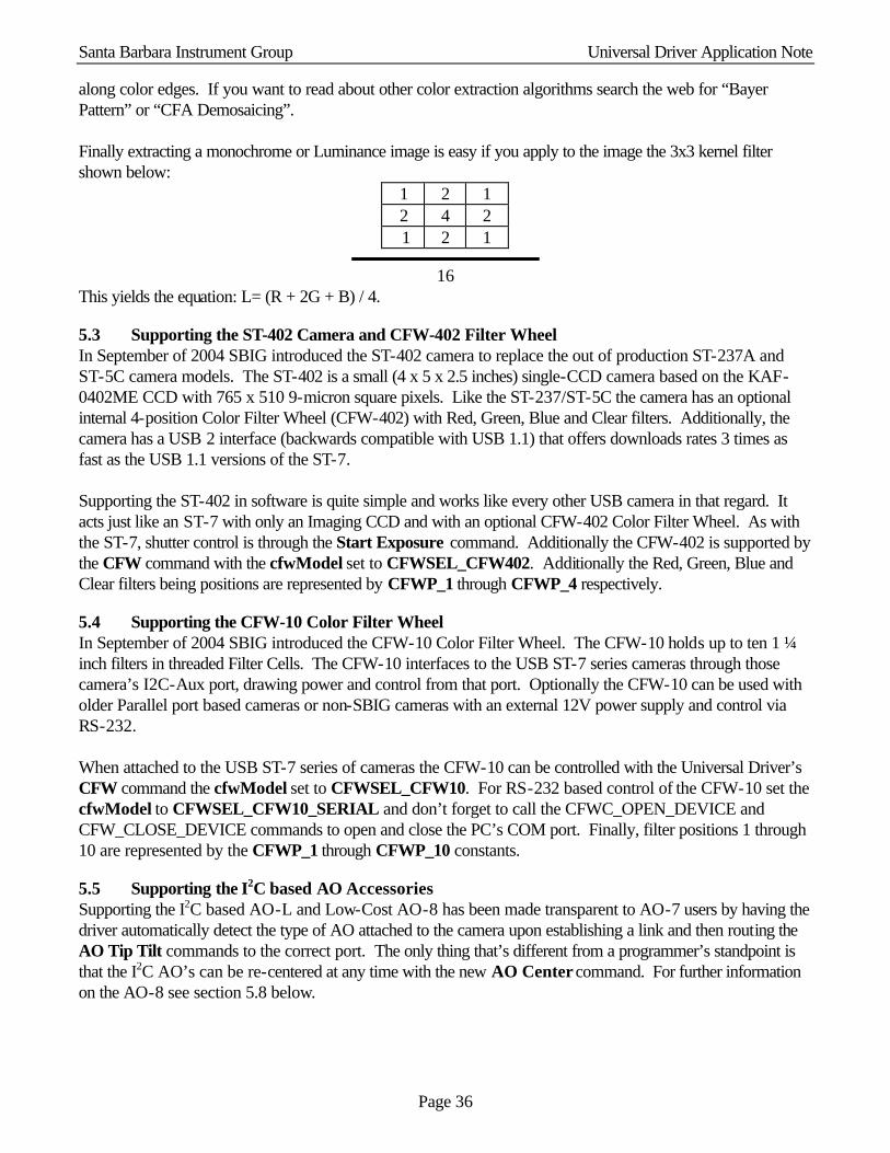
Santa Barbara Instrument Group Universal Driver Application Note
Page 36
along color edges. If you want to read about other color extraction algorithms search the web for “Bayer Pattern” or “CFA Demosaicing”. Finally extracting a monochrome or Luminance image is easy if you apply to the image the 3x3 kernel filter shown below:
1 2 1 2 4 2 1 2 1
16 This yields the equation: L= (R + 2G + B) / 4.
5.3 Supporting the ST-402 Camera and CFW-402 Filter Wheel In September of 2004 SBIG introduced the ST-402 camera to replace the out of production ST-237A and ST-5C camera models. The ST-402 is a small (4 x 5 x 2.5 inches) single-CCD camera based on the KAF-0402ME CCD with 765 x 510 9-micron square pixels. Like the ST-237/ST-5C the camera has an optional internal 4-position Color Filter Wheel (CFW-402) with Red, Green, Blue and Clear filters. Additionally, the camera has a USB 2 interface (backwards compatible with USB 1.1) that offers downloads rates 3 times as fast as the USB 1.1 versions of the ST-7. Supporting the ST-402 in software is quite simple and works like every other USB camera in that regard. It acts just like an ST-7 with only an Imaging CCD and with an optional CFW-402 Color Filter Wheel. As with the ST-7, shutter control is through the Start Exposure command. Additionally the CFW-402 is supported by the CFW command with the cfwModel set to CFWSEL_CFW402. Additionally the Red, Green, Blue and Clear filters being positions are represented by CFWP_1 through CFWP_4 respectively.
5.4 Supporting the CFW-10 Color Filter Wheel In September of 2004 SBIG introduced the CFW-10 Color Filter Wheel. The CFW-10 holds up to ten 1 ¼ inch filters in threaded Filter Cells. The CFW-10 interfaces to the USB ST-7 series cameras through those camera’s I2C-Aux port, drawing power and control from that port. Optionally the CFW-10 can be used with older Parallel port based cameras or non-SBIG cameras with an external 12V power supply and control via RS-232. When attached to the USB ST-7 series of cameras the CFW-10 can be controlled with the Universal Driver’s CFW command the cfwModel set to CFWSEL_CFW10. For RS-232 based control of the CFW-10 set the cfwModel to CFWSEL_CFW10_SERIAL and don’t forget to call the CFWC_OPEN_DEVICE and CFW_CLOSE_DEVICE commands to open and close the PC’s COM port. Finally, filter positions 1 through 10 are represented by the CFWP_1 through CFWP_10 constants.
5.5 Supporting the I2C based AO Accessories Supporting the I2C based AO-L and Low-Cost AO-8 has been made transparent to AO-7 users by having the driver automatically detect the type of AO attached to the camera upon establishing a link and then routing the AO Tip Tilt commands to the correct port. The only thing that’s different from a programmer’s standpoint is that the I2C AO’s can be re-centered at any time with the new AO Center command. For further information on the AO-8 see section 5.8 below.

Santa Barbara Instrument Group Universal Driver Application Note
Page 37
5.6 Supporting the I2C based CFW-9, CFW-L8 and CFW-L8G Color Filter Wheels Supporting the new I2C based color filter wheels is simply a matter of using the CFW command like every with other filter wheel. You can manually or auto-select the CFW model in the CFW command
5.7 Supporting the I2C based Motor Focus Accessory Supporting the new I2C based motor focus accessory is accomplished through the new Motor Focus command. You can manually or auto-select the Motor Focus model in the Motor Focus command
5.8 Supporting the I2C based low-cost A0-8 In September of 2007 we introduced the AO-8 which is an I2C based replacement for AO-7 for use with the small format ST series of cameras. The AO-8 displaces the image by tilting a transmissive glass plate where as the AO-7 displaced the image by tilting a 90° reflective mirror. This allowed us to make the A0-8 thinner. Here’s what you need to know about the AO-8 compared to the older AO-7:
1. The SBIG Universal Driver Library detects whether an AO-8 is attached to the camera in the CC_ESTABLISH_LINK call, and if so it formats and sends AO commands to the I2C port. If no A0-8 is detected then AO commands are formatted for an AO-7 and sent to the AO/CFW/SCOPE port. This is completely transparent to any Application level software and only requires that the AO-8 be attached at the time you establish the communications link.
2. Compared to an AO-7, the AO-8 calibration vectors are very perpendicular and in fact, due to the transmissive design the Calibration Vectors are actually fixed: they repeat from unit to unit and camera to camera. Because of this users may skip the Calibration step if you proved them with default Calibration Vectors as described below:
Relay -> X+ X- Y+ Y-
Calibration Vector Standard Orientation
Right Left Down Up
Calibration Vector Rotated Orientation
Left Right Up Down
Speed with 237 Guider 2.25 Same Same Same
Speed with 211 Guider 1.0 Same 1.2 Same
Note that the Calibration Vectors change orientation depending on whether the AO-8 is attached in the Standard Orientation with its cable pointed towards the camera’s Power Cable or rotated 180° as is required when used with a CFW.
3. The capabilitiesBits field of the CCD_INFO_EXTENDED2_IMAGING request of the CC_GET_CCD_INFO command contains a field that allows you to find out whether an AO-8 was detected when the link was established to the camera. You can use this to preload the calibration vectors for the AO-8 as described in paragraph 2 above.
5.9 Supporting the ST-4000XCM Single Shot Color Camera In September of 2007 we introduced the ST-4000XCM. The ST-4000XCM is a 4-megapixel single-shot-color camera in the smaller ST-series camera body. Here’s what you need to know that’s different about the ST-4000XCM:
Santa Barbara Instrument Group Universal Driver Application Note
Page 38
1. When you establish a link to the ST-4000XCM the driver returns a cameraType code of ST4K_CAMERA (18) as defined in the sbigudrv.h file.
2. Like the STL version of this camera, the ST-4000XCM has the imager rotated 90° clockwise relative to the tracking CCD. This tends to easily disorient users who are used to the standard orientation. For this reason we recommend you automatically rotate ST-4000XCM images 90° clockwise for the user. That’s what we do in CCDOps. For full-frame images that’s fairly simple because the imager itself is square at 2048 x 2048 pixels. It gets a little more complicated with rectangular sub-frames but it’s not impossible. Just remember that displayed images have been rotated 90° CW so rotate any user selected sub-frame coordinates 90° CCW to get to the CCD coordinates.. Usually we like to take care of issues like this in the driver so that they are taken care for you automatically but in this case we could not because the API to the driver is row based, not area based.
5.10 Supporting the STX Cameras Towards the end of 2008 we introduced the STX family of cameras. This line of cameras supports multiple models of CCDs and offers both USB and Ethernet connectivity. While we tried to minimize the impact on developers of adding support for this camera to existing software, the architectural change of including an on-camera frame buffer requires adding the following capabilities to existing software:
1. With the STX you need to use the Start Exposure 2 command instead of the Start Exposure command so you can specify the pixel coordinates of the desired readout area. You can use the Start Exposure 2 command with the older cameras as well.
2. Even though you use the Start Exposure 2 command you should continue to use the Start Readout and End Readout commands and pass the same values for the binning and image coordinates to these other commands. You should also use the Dump Lines command to discard unused rows at the top of the image.
6. Revision History This section details the recent changes to this specification and supporting software since the initial release of the ST-7 Driver.
Changes Incorporated in Version 1.90 • Added support for the PixCel255. • Added a response to the EstablishLink command that reports the type of camera found. • Renamed the main function SBIGUDrvCommand() from ST7Command() since it now supports the
PixCel255 in addition to the ST-7/8. • Added the new Error Code Unknown Camera. • Added several ABG rates to the abgState item in the Start Exposure command. • Added status results to the Pulse Out command that reports the current filter in position in the
PixCel255. • Added a type 3 request to the Get CCD Info command to report data on the PixCel255 vane/filter
wheel configuration.
Changes Incorporated in Version 1.96 • Renamed ST-5C to PixCel255. • Set PixCel255 e-/ADU based upon production hardware.
Changes Incorporated in Version 2.1 • Made 32 bit version available for Windows 95. • Added the Open Driver and Close Driver commands.

Santa Barbara Instrument Group Universal Driver Application Note
Page 39
• Added Driver Not Found, Driver Not Open and Driver Not Closed error codes for Open Driver and Close Driver functions.
• Added the Nx1, Nx2 and Nx3 readout modes for the ST-7/8 • Added the 1x1, 2x2 and 3x3 off-chip binning modes for the ST-7/8
Changes incorporated through Version 2.6 • Added support for the PixCel237 and the AO-7.
Changes incorporated through Version 2.70 • Added the AO Delay command for generating millisecond level delays. • Added the End Readout command for preparing the CCD for the idle state. • Added the ability to Freeze the TE Cooler for readout through the Set Temperature Regulation
command. • Added the REGULATION_FOZEN_MASK bit to the enabled field of the Query Temperature
Status command results for detecting whether the TE cooler is frozen.
Changes incorporated through Version 3.3 • Added the Open Device and Close Device commands. • Added support for the ST-9 • Added support for the ST-10 • Added support for the ST-1K • Added support for an OEM version of the STV with Parallel Port • Added support for the ST-237A
Changes incorporated through Version 4.0 • Added the START_SKIP_VDD option to the ccd item of the Start Readout command for higher
imaging throughput. • Changed calling convention to “stdcall” for compatibility with Visual C++ and Visual Basic. • Changed calling struct member alignment to the default 8 bytes for compatibility. • Made a single function callable from Windows 9X and Windows NT/2000/XP, using
SBIGUDrvCommand() to replace ParDrvCommand() and ParDeviceCommandNH(). • Calls to Open Device and Close Device are now required. • Added support for the USB and Ethernet based cameras and accessories. • Removed the port information from the CC_ESTABLISH_LINK command and added it to the
CC_OPEN_DEVICE command for compatibility with multiple hardware interfaces. • Added the CC_GET and CC_SET_DRIVER_HANDLE commands for supporting multiple
cameras per application. • Added documentation for the Get US Timer, Set IRQL, Get IRQL commands. • Added the Get Line , Get Link Status , Start Readout and Get Error String commands. • Changed the minimum ST-7/8/9/10/1K exposure from 0.11 seconds to 0.12 seconds.
Changes incorporated in Version 4.1 • Added readoutMode 9 with 9x9 binning to the ST-7/8/etc for faster focus mode throughput.
Changes incorporated in Version 4.2 • Added support for the KAI2000 (ST-2K) and the TC-237 Tracking CCD • Added requests 4 and 5 to the Get CCD Info command for use with the new frame transfer CCDs
(TC237 Guider, KAI2000 Imager) when used with Start Exposure/End Exposure commands are bypassed as is typically done with AO exposures.
• Added the SBIGDriverChecker.exe Utility for updating the drivers to the current version.
Santa Barbara Instrument Group Universal Driver Application Note
Page 40
Changes incorporated in Version 4.21 • Added the Set Driver Control and Get Driver Control commands. • Fixed a bug in the documentation where the ipAddress was ushort instead of ulong in the Open
Device command.
Changes incorporated in Version 4.22 • Added the USB AD Control command. • Added the DCP_CALL_JOURNAL_ENABLE and DCP_IVTOH_RATIO control parameters to
the Set Driver Control command. • Added the \Tools folder to the SBIG Universal Driver distribution with the EthSim.exe,
SBIGUDRVJournalRx.exe, GetPortD.exe and SetClock.exe utility programs included. • Released version 1.2 of the SBIGDriverChecker program that fixes a bug where some drivers
could be installed in the wrong directory on some systems. Also removes those improperly installed drivers.
• Fix a bug in the documentation where the SBIGUnivDrvCommand() function was misnamed. • Fix a bug in the documentation for the Activate Relay command regarding the bits in the command
status.
Changes incorporated in Version 4.23 • Fix many grammatical and typos with the much appreciated help of Andrew Mattingly.
Changes incorporated in Version 4.24 • Documented the DCP_IVTOH_RATIO and added the DCP_USB_FIFO_SIZE device control
parameters which are Read or Set with the Get/Set Driver Control function. • Extended the Exposure Range of the ST-2K with its Electronic Shutter from 0.12 seconds down to
0.01 seconds. Changes incorporated in Version 4.27
• added the Query USB command and the DEV_USB1, DEV_USB2, DEV_USB3 and DEV_USB4 enums to the Open Device command.
Changes incorporated in Version 4.28
• Added the Get Pentium Cycle Count and RW USB I2C commands. Changes incorporated in Version 4.29/4.30
• Added the CFW command. • Added support for the ST-L Large Format Camera. This mainly involved added support for the
Remote Guiding Head CCD (CCD enum value 2) • Added the BitIO command.
Changes incorporated in Version 4.30, 3rd Edition (Version 4.29 Build 16 of DLL)
• Made the CFW-L in the ST-L emulate a CFW-8 in the Pulse Out command. • Added further support for the ST-L and CFW-L. • Added support for the ST-402 camera and CFW-402 color filter wheel. • Added the BITO_FPGA_WE sub-command to the Bit IO command. • Added the DCP_USB_PIXEL_DL_ENABLE driver control parameter. • Made one set of Driver Control Parameters for the driver vs. one per Handle. • Added the CFWSEL_AUTO select code for the CFW command.
Santa Barbara Instrument Group Universal Driver Application Note
Page 41
Changes incorporated in Version 4.30, 4th Edition (Version 4.30 of DLL) • Added the DCP_HIGH_THROUGHPUT driver control parameter. • Allow 6 positions with the CFW-8 in the CFW command to support third party Color Filter
Wheels that mimic the CFW-8 but have 6 filters. Changes incorporated in Version 4.35
• Documented the Update Clock function as inoperable. • Add a new Section 2 describing the particulars of the Windows, Macintosh OSX and Linux
versions of the library. • Added the USB Loader Request to the Get Driver Info command for returning information about
the USB Loader driver. • Corrected the documentation regarding the ST-L’s external shutter in the Remote Tracking Head
via the Miscellaneous Control command. While the external shutter mimics the internal shutter for the Start Exposure command it does not with the Miscellaneous Control command. There you use separate control codes to affect the external shutter.
Changes incorporated in Version 4.37
• Added support for millisecond exposures with Interline CCD cameras like the ST-2K, STL-11K and STL-4020. See the Start Exposure and Get CCD Info commands.
• For Single Shot Color cameras like the ST-2001XCM the name item in the Get CCD Info command contains the word “Color”. You can use this to detect whether to treat the data as Color or Monochrome for example.
• Added the DCP_VDD_OPTIMIZED parameter to the Get/Set Device Control commands. • Fixed a bug where the DLL would not load under Windows 95. • Added support for Trigger In capability with USB cameras. See the Start Exposure command. • Added support for the very old CFW-6A to the CFW command. • Added section 5.2 regarding Color CCDs.
Changes incorporated in Version 4.40
• Fixed a bug where CB_CCD_TYPE_FRAME_TRANSFER wasn't getting set for the STL-11K and STL-4020.
• Auto-select the USB driver (Standard or Alternate) based upon establishing a link. • Added support for the KAI-2020 CCD version of the ST-2K • Fixed a bug that would cause bright lines every 256 line in TDI mode. • Added the DCP_AUTO_AD_GAIN device control parameter. • Added support for the STL-1301 model of the Large Format camera. • Refer to the ST-402 by it’s proper name instead of the development name (ST-F).
Changes incorporated in Version 4.42
• Added documentation for the ST-402, CFW-402 and CFW-10 products. Changes incorporated in Version 4.42, 2nd Edition
• Refer to the CFW-402 instead of the development name CFW-F. Changes incorporated in Version 4.42, 3rd Edition

Santa Barbara Instrument Group Universal Driver Application Note
Page 42
• Expanded the documentation for the CFW Command including support for the CFWC_OPEN_DEVICE and CFWC_CLOSE_DEVICE sub-commands required for RS-232 control of the CFW-10.
Changes incorporated in Version 4.43
• Brought Linux and Macintosh drivers up to parity with the Windows version and released all as Version 4.43.
• No changes to API or documentation. Bug fixes in drivers only. Changes incorporated in Version 4.44 Build 2
• Added the number of filter positions to the cfwResult2 entry of the cfwResults struct for the CFWG_FIRMWARE_VERSION query of the CFWC_GET_INFO command.
• On cameras with a CFW-10 attached the Cfw Command will auto detect the CFW-10. • Added support for the AOL, the AO for the STL to the AO Tip Tilt command.
Changes incorporated in Version 4.47
• Added support for the AOL (Large Format AO). The AOL is supported on the USB based ST-7/8/9/10/2K and STL series of cameras. The driver detects the type of AO attached to the camera in the Establish Link command and handles it accordingly. From the programming side the AOL acts just like an AO-7, but requires you to use the new AO Center command to recenter the AO.
• Added the Center AO command to force the AOL to re-center using the mechanical home sensors. • Added the ability to disable the Auto Bias feature through the DriverChecker utility. • Added support for the TDI mode on the interline Cameras like the ST-2000 and STL-11000. • Added support for the external Remote Guide Head on the USB based ST-7/8/9/10/2K cameras.
This includes setting flags in the capabilitiesBits field of the CCDInfoResults4 struct for Request 5 when an external Tracking Head is supported in hardware.
Changes incorporated in Version 4.52
• Added support for the KAI-11002 based STL-11K cameras. • Added the ability to disable the vertical flush for KAI based cameras which gets used with ms level
exposures to fix a smearing issue. • Cleaned up and fixed a CFW-10 bug. • Ported Mac versions to support the Intel based Macs. • Fixed a bug in Serial based CFW-10 code. • Fixed an intermittent Share error. • Added ability to enable journaling through the Registry on Windows. • Fixed a bug with the AO-L that would cause errors on large moves. • Added support for the CFW-9.
Changes incorporated in Version 4.54 • Added support for the Biorad TDI mode of the ST-402. • Added the Motor Focus command to support the Motor Focus accessories (section 5.7). • Updated the help sections on supporting the new I2C based CFW and AO accessories.
Changes incorporated in Version 4.55 • Added preliminary support for the upcoming ST-H camera models. • Added support for the low-cost AO (AO-8)
Santa Barbara Instrument Group Universal Driver Application Note
Page 43
Changes incorporated in Version 4.57
• Added further support for the low-cost AO-8 (section 5.8). • Added support for the ST-4000XCM, a small format 4-megapixel single shot color camera
(section 5.9). Changes incorporated in Version 4.60 Build 9
• Added the Start Exposure 2 command (section 3.2.1) for use with the STX. • Added the Advanced Results to the Query Temperature Status command (section 3.3.2). • Added the Query Ethernet command for discovering Ethernet based SBIG Cameras (section
3.5.16).