Embed Size (px)
Citation preview

SBE 21 SEACATThermosalinograph
Conductivity and Temperature Recorderwith RS-232 Interface
User’s ManualSea-Bird Electronics, Inc.1808 136th Place NEBellevue, Washington 98005 USATel: 425/643-9866 Manual Version #011, 02/15/02Fax:425/643-9954 Firmware Version 4.2 and later

2
Limited Liability Statement
Extreme care should be exercised when using or servicing this equipment. It should be used or servicedonly by personnel with knowledge of and training in the use and maintenance of oceanographicelectronic equipment.
SEA-BIRD ELECTRONICS, INC. disclaims all product liability risks arising from the use or servicingof this system. SEA-BIRD ELECTRONICS, INC. has no way of controlling the use of this equipmentor of choosing the personnel to operate it, and therefore cannot take steps to comply with lawspertaining to product liability, including laws which impose a duty to warn the user of any dangersinvolved in operating this equipment. Therefore, acceptance of this system by the customer shall beconclusively deemed to include a covenant by the customer to defend, indemnify, and hold SEA-BIRDELECTRONICS, INC. harmless from all product liability claims arising from the use or servicing ofthis system.
Table of Contents
3
Table of Contents
Section 1: Introduction ........................................................................ 5About this Manual ............................................................................................. 5How to Contact Sea-Bird .................................................................................. 5Unpacking the SBE 21 ...................................................................................... 6
Section 2: Description of the SBE 21 .................................................. 7System Description ........................................................................................... 7SBE 21 Specifications ....................................................................................... 9SBE 21 Dimensions and Bulkhead Connectors .............................................. 10Data I/O........................................................................................................... 11Data Storage .................................................................................................... 11Remote Temperature Sensor (optional)........................................................... 11
Section 3: Installing the System ........................................................ 12Installing Software .......................................................................................... 12
SEASOFT-Win32 .................................................................................... 12SEASOFT-DOS ....................................................................................... 12
System Schematic and Installation Guidelines................................................ 13Mechanical Installation ................................................................................... 15Electrical Installation....................................................................................... 16
Connecting the SBE 21 to the NMEA Interface Box............................... 16Connecting the SBE 21 to Ground and to Auxiliary Sensors................... 16Connecting the NMEA Interface Box ...................................................... 17
Section 4: Setting Up the SBE 21 ...................................................... 18Setting NMEA Interface Box Dip Switch ....................................................... 18Power and Communications Test and SBE 21 Setup in SEATERM .............. 19Command Descriptions ................................................................................... 23Checking SBE 21 Configuration (.con) File in SEASAVE............................. 31Data Output Formats ....................................................................................... 32
Section 5: Setting Up the NMEA Interface ...................................... 33Setting NMEA Interface Box PCB Dip Switch............................................... 33NMEA Operating Modes ................................................................................ 34Setting Up and Testing NMEA ....................................................................... 35Troubleshooting NMEA Interface................................................................... 37Setting Up SBE 21 Configuration (.con) File.................................................. 37
Section 6: Operating the System ....................................................... 38Acquiring Real-Time Data with SEASAVE ................................................... 38Uploading SBE 21 Data from Memory........................................................... 42
Section 7: Routine Maintenance and Calibration .......................... 45Corrosion Precautions ..................................................................................... 45Removing Sensor/Electronics Module from SBE 21 Water Jacket ................ 45Cleaning and Storage....................................................................................... 46Replacing Anti-Foul Cylinders ....................................................................... 48Sensor Calibration ........................................................................................... 49
Conductivity Sensor Calibration .............................................................. 49Temperature Sensor Calibration............................................................... 49
Table of Contents
4
Section 8: Troubleshooting................................................................ 50Problem 1: Unable to Communicate with NMEA Interface Box.................... 50Problem 2: Unable to Communicate with SBE 21 .......................................... 50Problem 3: No Data Recorded......................................................................... 50Problem 4: Nonsense or Unreasonable Data ................................................... 51Problem 5: Salinity Lower than Expected....................................................... 51Problem 6: Program Corrupted ....................................................................... 51
Glossary............................................................................................... 52
Appendix I: Functional Description ................................................. 53Sensors ............................................................................................................ 53Sensor Interface............................................................................................... 53Real-Time Clock ............................................................................................. 53Power............................................................................................................... 53
Appendix II: Electronics Disassembly/Reassembly ........................ 54Disassembly .................................................................................................... 54Reassembly...................................................................................................... 55
Appendix III: Command Summary ................................................. 56
Appendix IV: Replacement Parts ..................................................... 58
Index .................................................................................................... 59
Warranty PolicyService InformationCalibration CertificatesSchematics
Section 1: Introduction
5
Section 1: IntroductionThis section includes contact information and photos of a standardSBE 21 shipment.
About this ManualThis manual is to be used with the SBE 21 SEACAT ThermosalinographConductivity and Temperature Recorder.
It is organized to guide the user from installation through operation and datacollection. We’ve included detailed specifications, command descriptions,maintenance and calibration information, and helpful notes throughoutthe manual.
Sea-Bird welcomes suggestions for new features and enhancements of ourproducts and/or documentation. Please e-mail any comments or suggestions [email protected].
How to Contact Sea-BirdSea-Bird Electronics, Inc.1808 136th Place NortheastBellevue, Washington 98005 USA
Telephone: 425-643-9866Fax: 425-643-9954E-mail: [email protected]: http://www.seabird.com
Business hours:Monday-Friday, 0800 to 1700 Pacific Standard Time
(1600 to 0100 Universal Time)Except from April to October, when we are on ‘summer time’
(1500 to 0000 Universal Time)
Section 1: Introduction
6
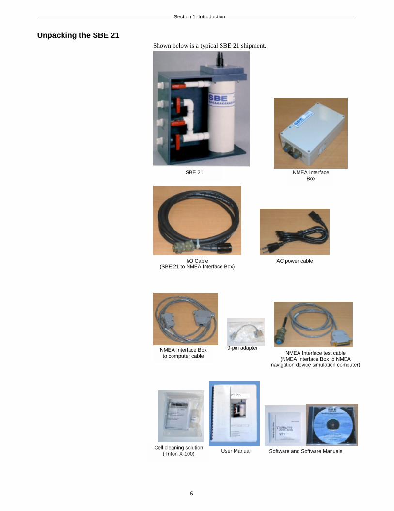
Unpacking the SBE 21Shown below is a typical SBE 21 shipment.
Cell cleaning solution(Triton X-100)
SBE 21
User Manual
SBE 21 SEACATThermosalinograph
Software and Software Manuals
NMEA InterfaceBox
I/O Cable(SBE 21 to NMEA Interface Box)
NMEA Interface Boxto computer cable
AC power cable
NMEA Interface test cable(NMEA Interface Box to NMEA
navigation device simulation computer)
9-pin adapter
Section 2: Description of the SBE 21
7
Section 2: Description of the SBE 21This section describes the functions and features of the SBE 21,including specifications and dimensions.
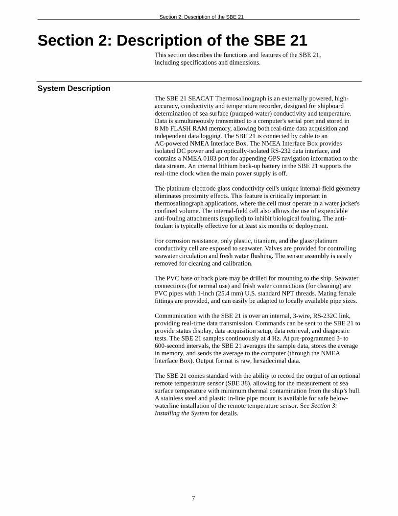
System DescriptionThe SBE 21 SEACAT Thermosalinograph is an externally powered, high-accuracy, conductivity and temperature recorder, designed for shipboarddetermination of sea surface (pumped-water) conductivity and temperature.Data is simultaneously transmitted to a computer's serial port and stored in8 Mb FLASH RAM memory, allowing both real-time data acquisition andindependent data logging. The SBE 21 is connected by cable to anAC-powered NMEA Interface Box. The NMEA Interface Box providesisolated DC power and an optically-isolated RS-232 data interface, andcontains a NMEA 0183 port for appending GPS navigation information to thedata stream. An internal lithium back-up battery in the SBE 21 supports thereal-time clock when the main power supply is off.
The platinum-electrode glass conductivity cell's unique internal-field geometryeliminates proximity effects. This feature is critically important inthermosalinograph applications, where the cell must operate in a water jacket'sconfined volume. The internal-field cell also allows the use of expendableanti-fouling attachments (supplied) to inhibit biological fouling. The anti-foulant is typically effective for at least six months of deployment.
For corrosion resistance, only plastic, titanium, and the glass/platinumconductivity cell are exposed to seawater. Valves are provided for controllingseawater circulation and fresh water flushing. The sensor assembly is easilyremoved for cleaning and calibration.
The PVC base or back plate may be drilled for mounting to the ship. Seawaterconnections (for normal use) and fresh water connections (for cleaning) arePVC pipes with 1-inch (25.4 mm) U.S. standard NPT threads. Mating femalefittings are provided, and can easily be adapted to locally available pipe sizes.
Communication with the SBE 21 is over an internal, 3-wire, RS-232C link,providing real-time data transmission. Commands can be sent to the SBE 21 toprovide status display, data acquisition setup, data retrieval, and diagnostictests. The SBE 21 samples continuously at 4 Hz. At pre-programmed 3- to600-second intervals, the SBE 21 averages the sample data, stores the averagein memory, and sends the average to the computer (through the NMEAInterface Box). Output format is raw, hexadecimal data.
The SBE 21 comes standard with the ability to record the output of an optionalremote temperature sensor (SBE 38), allowing for the measurement of seasurface temperature with minimum thermal contamination from the ship’s hull.A stainless steel and plastic in-line pipe mount is available for safe below-waterline installation of the remote temperature sensor. See Section 3:Installing the System for details.
Section 2: Description of the SBE 21
8
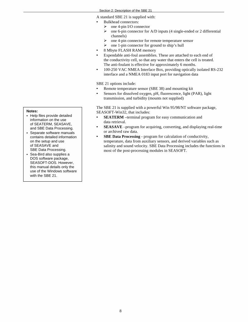
A standard SBE 21 is supplied with:• Bulkhead connectors:
! one 4-pin I/O connector! one 6-pin connector for A/D inputs (4 single-ended or 2 differential
channels)! one 4-pin connector for remote temperature sensor! one 1-pin connector for ground to ship’s hull
• 8 Mbyte FLASH RAM memory• Expendable anti-foul assemblies. These are attached to each end of
the conductivity cell, so that any water that enters the cell is treated.The anti-foulant is effective for approximately 6 months.
• 100-250 VAC NMEA Interface Box, providing optically isolated RS-232interface and a NMEA 0183 input port for navigation data
SBE 21 options include:• Remote temperature sensor (SBE 38) and mounting kit• Sensors for dissolved oxygen, pH, fluorescence, light (PAR), light
transmission, and turbidity (mounts not supplied)
The SBE 21 is supplied with a powerful Win 95/98/NT software package,SEASOFT-Win32, that includes:• SEATERM –terminal program for easy communication and
data retrieval.• SEASAVE –program for acquiring, converting, and displaying real-time
or archived raw data.• SBE Data Processing - program for calculation of conductivity,
temperature, data from auxiliary sensors, and derived variables such assalinity and sound velocity. SBE Data Processing includes the functions inmost of the post-processing modules in SEASOFT.
Notes:• Help files provide detailed
information on the useof SEATERM, SEASAVE,and SBE Data Processing.
• Separate software manualscontains detailed informationon the setup and useof SEASAVE andSBE Data Processing.
• Sea-Bird also supplies aDOS software package,SEASOFT-DOS. However,this manual details only theuse of the Windows softwarewith the SBE 21.
Section 2: Description of the SBE 21
9
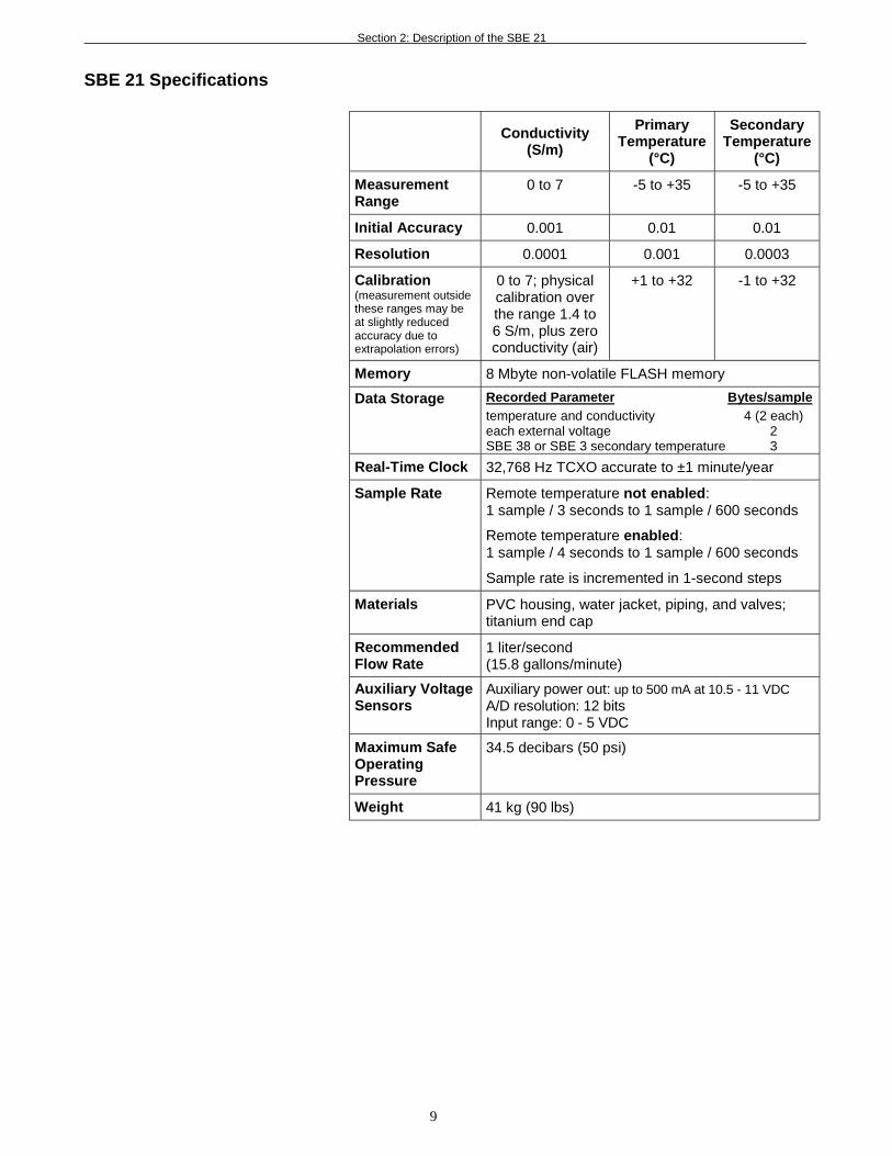
SBE 21 Specifications
Conductivity(S/m)
PrimaryTemperature
(°C)
SecondaryTemperature
(°C)
MeasurementRange
0 to 7 -5 to +35 -5 to +35
Initial Accuracy 0.001 0.01 0.01
Resolution 0.0001 0.001 0.0003
Calibration(measurement outsidethese ranges may beat slightly reducedaccuracy due toextrapolation errors)
0 to 7; physicalcalibration overthe range 1.4 to6 S/m, plus zeroconductivity (air)
+1 to +32 -1 to +32
Memory 8 Mbyte non-volatile FLASH memory
Data Storage Recorded Parameter Bytes/sampletemperature and conductivity 4 (2 each)each external voltage 2SBE 38 or SBE 3 secondary temperature 3
Real-Time Clock 32,768 Hz TCXO accurate to ±1 minute/year
Sample Rate Remote temperature not enabled:1 sample / 3 seconds to 1 sample / 600 seconds
Remote temperature enabled:1 sample / 4 seconds to 1 sample / 600 seconds
Sample rate is incremented in 1-second steps
Materials PVC housing, water jacket, piping, and valves;titanium end cap
RecommendedFlow Rate
1 liter/second(15.8 gallons/minute)
Auxiliary VoltageSensors
Auxiliary power out: up to 500 mA at 10.5 - 11 VDCA/D resolution: 12 bitsInput range: 0 - 5 VDC
Maximum SafeOperatingPressure
34.5 decibars (50 psi)
Weight 41 kg (90 lbs)
Section 2: Description of the SBE 21
10
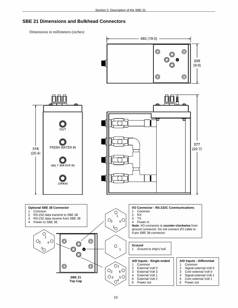
SBE 21 Dimensions and Bulkhead Connectors
Dimensions in millimeters (inches)
2
1
4
3
1
2
1
6
43 5
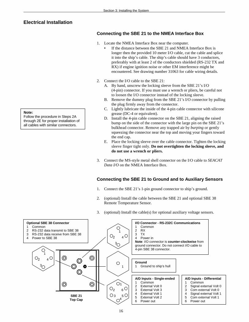
I/O Connector - RS-232C Communications1 Common2 RX3 TX4 Power inNote: I/O connector is counter-clockwise fromground connector. Do not connect I/O cable to4-pin SBE 38 connector.
Ground1 Ground to ship’s hull
A/D Inputs - Single-ended1 Common2 External Volt 03 External Volt 34 External Volt 15 External Volt 26 Power out
A/D Inputs - Differential1 Common2 Signal external Volt 03 Com external Volt 04 Signal external Volt 15 Com external Volt 16 Power out
2
1
4
3
Optional SBE 38 Connector1 Common2 RS-232 data transmit to SBE 383 RS-232 data receive from SBE 384 Power to SBE 38
SBE 21Top Cap
Section 2: Description of the SBE 21
11
Data I/OThe SBE 21 receives set-up instructions and outputs diagnostic information orpreviously recorded data via a three-wire RS-232C link, and is factory-configured for 9600 baud, 7 data bits, 1 stop bit, and even parity. SBE 21RS-232 levels are directly compatible with standard serial interface cards (IBMAsynchronous Communications Adapter or equal). The communications baudrate can be changed using the BAUD= command (see Command Descriptions inSection 4: Setting Up the SBE 21 for details).
Data StorageThe SBE 21 has an 8 Mbyte FLASH memory. Shown below are examples ofavailable data storage for several configurations. (See SBE 21 Specifications inthis section for storage space required for each parameter.)
Remote Temperature Sensor (optional)
The SBE 21 has the ability to record the output of an external SBE 38temperature sensor. Often, the SBE 21 is mounted in the interior of the vessel.In this configuration the recorded conductivity is correct, but the watertemperature has changed as it has passed through the plumbing system. Theremote temperature sensor can be placed in a location that provides moreaccurate measurement of the sea surface water temperature. The ideallocation for the remote sensor is at the seawater intake (before the pump)near the bow of the ship. This minimizes contamination of the surfacetemperature measurement by the ship’s own thermal mass.
Always use the data from the temperature sensor on the SBE 21, not fromthe remote temperature sensor, to compute salinity. Conductivity has astrong thermal coefficient; therefore, it is critical to know the temperature ofthe water when the conductivity sensor samples it in order to compute salinitycorrectly. On a typical installation, there may be 20 to 30 meters of plumbingbetween the remote temperature sensor and the SBE 21. As the water flowsthrough the pipes it changes temperature dramatically, making the data fromthe remote temperature sensor an inaccurate representation of the temperaturewhen the water reaches the conductivity sensor. Use the remote temperaturesensor only to report surface temperature.
Note that the remote temperature sensor can be added to the system at anytime, and does not need to be part of the original order for the SBE 21. Nomodifications to the SBE 21 are required to integrate the remote sensor, otherthan programming the SBE 21 to accept the sensor signal and updating theconfiguration (.con) file.
Example 1: no auxiliary sensorsT & C = 4 bytes/sampleStorage space ≈ 8,000,000 / 4 ≈ 2,000,000 samples
Example 2: 4 external voltages, SBE 38 secondary temperature sensorT & C = 4 bytes/sampleExternal voltages = 2 bytes/sample x 4 voltages = 8 bytes/sampleSBE 38 = 3 bytes/sampleStorage space ≈ 8,000,000 /(4 + 8 + 3) ≈ 533,333 samples
Note:If the FLASH memory is filled tocapacity, data sampling andtransmission of real-time datacontinue, but excess data is notsaved in memory. The SBE 21will not overwrite the datastored in memory.
Section 3: Installing the System
12
Section 3: Installing the SystemThis section provides instructions for:• Installing software• System installation guidelines• Mounting and wiring the SBE 21 and NMEA Interface Box
Installing SoftwareIf not already installed, install Sea-Bird software programs on your computerusing the supplied software CD.
SEASOFT-Win32
1. With the CD in your CD drive, double click on Seasoft-Win32.exe.
2. Follow the dialog box directions to install the software.
The installation program allows you to install the desired components.Install all the components, or (for the SBE 21) just install SEATERM(terminal program), SEASAVE (real-time data acquisition program), andSBE Data Processing (data processing program). The default location for thesoftware is c:/Program Files/Sea-Bird. Within that folder is a sub-directory foreach component.
SEASOFT-DOS
1. With the CD in your CD drive, copy the Seasoft.dos folder, whichcontains three files.
2. Paste the Seasoft.dos folder in the desired location on your hard drive.
3. In the Seasoft.dos folder on your hard drive, double click on sinstall.batto install the software.
Note:SEASOFT-DOS containsNMEA navigation simulationprograms that may be useful fortroubleshooting purposes. Seethe NMEA Interface Box manualfor details.
Section 3: Installing the System
13
System Schematic and Installation Guidelines
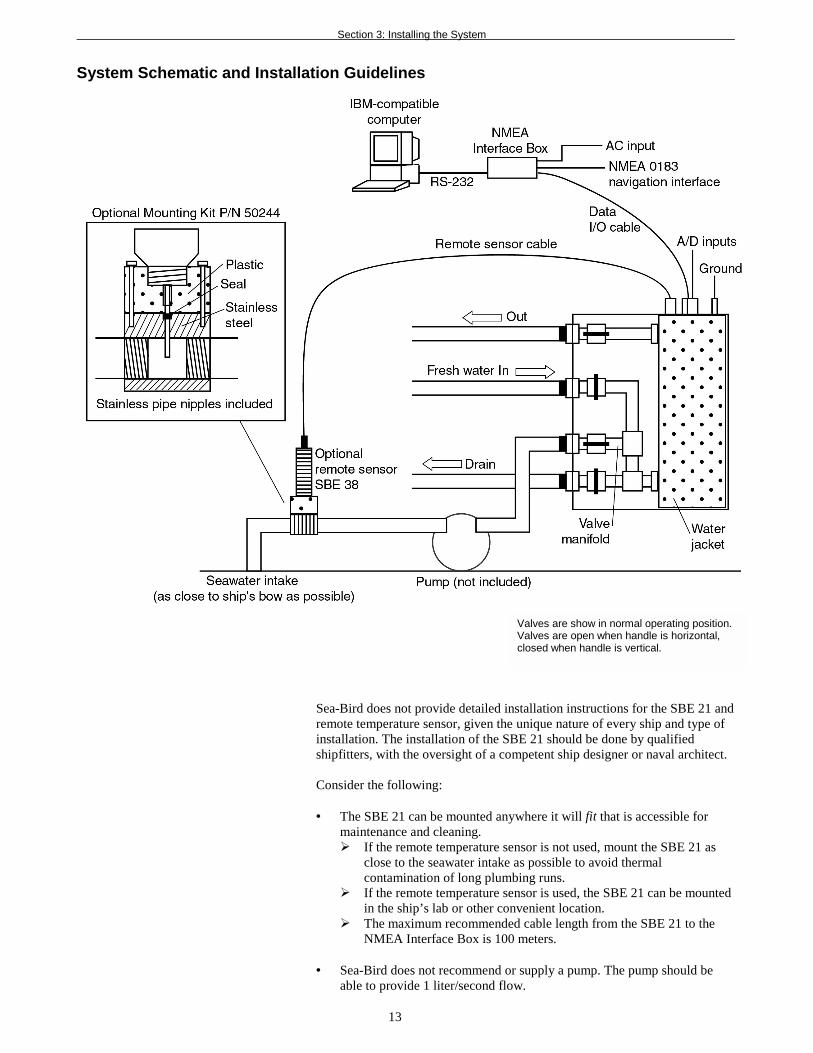
Sea-Bird does not provide detailed installation instructions for the SBE 21 andremote temperature sensor, given the unique nature of every ship and type ofinstallation. The installation of the SBE 21 should be done by qualifiedshipfitters, with the oversight of a competent ship designer or naval architect.
Consider the following:
• The SBE 21 can be mounted anywhere it will fit that is accessible formaintenance and cleaning.! If the remote temperature sensor is not used, mount the SBE 21 as
close to the seawater intake as possible to avoid thermalcontamination of long plumbing runs.
! If the remote temperature sensor is used, the SBE 21 can be mountedin the ship’s lab or other convenient location.
! The maximum recommended cable length from the SBE 21 to theNMEA Interface Box is 100 meters.
• Sea-Bird does not recommend or supply a pump. The pump should beable to provide 1 liter/second flow.
Valves are show in normal operating position.Valves are open when handle is horizontal,closed when handle is vertical.
Section 3: Installing the System
14
• Bubbles in the plumbing of a flow-through system are a common problemand will cause noisy salinity data. Depending on the chosen design of apermanent seawater supply (including pump, intake fitting, pipes, etc.),you may find that a de-bubbling device is needed to separate bubbles fromthe water before it enters the SBE 21. Not all ships require de-bubblers,but many do for best quality salinity data. Note that large single pointsalinity spikes can be removed with the WILD EDIT module inSBE Data Processing.
• Cabling should be routed as cleanly as possible, avoiding sources of noise.Electric motors are a particular problem. Avoid routing the cable next togenerators and air conditioners.
• If practical, the optional SBE 38 remote temperature sensor should bemounted outside the hull. However, the remote temperature sensor isusually mounted in the remote sensor mount kit, which has 1-inch pipethreads on each end. The mount kit must be plumbed into your seawatersystem. It should be installed as close to the seawater intake as possible(before the pump), near the bow of the ship. Since the installation will bebelow the water line, consult with your ship's engineer / naval architect /shipyard regarding the actual installation. Sea-Bird cannot offer advice inthis matter as each ship is different and plumbing regulations vary.
• The SBE 21 can record a maximum of four auxiliary voltages fromauxiliary sensors. However, Sea-Bird has not developed methods for themechanical integration of these auxiliary sensors with the SBE 21.When integrating auxiliary sensors with the SBE 21, consider thefollowing issues:! Installation of the sensors in a flow-through chamber that receives the
outflow from the SBE 21.! Design of the flow-through chamber so sensors can be removed and
replaced for service and calibration.! Protection of some auxiliary sensors (fluorometer, dissolved oxygen
sensor, etc.) from bio-fouling.

Section 3: Installing the System
15
Mechanical Installation
1. A new SBE 21 is shipped with anti-foul cylinders pre-installed. Verifythat the cylinders are installed (see Section 7: Routine Maintenance andCalibration for access to and replacement of the anti-foul cylinders).
2. Mount the SBE 21 at the desired location:• Orient the SBE 21 with the bulkhead connectors at the top.• Provide minimum top clearance of 559 mm (22 inches) for removal
of the sensor/electronics module from the water jacket.• Drill the PVC base or backplate, and mount to the ship using
machine bolts.
3. Install the piping connections to the SBE 21. The connectors are1-inch (25.4 mm) National (USA) threads. Female mating fittings suitablefor connecting to PVC plastic pipe with glue are provided; they may bemodified for use with existing piping.A. Connect the Out fitting to the shipboard drain or to the low pressure
side of salt water supply.B. Connect the Fresh Water In fitting to the shipboard fresh
water supply.C. Connect the Salt Water In fitting to the shipboard sea surface water
intake line.D. Connect the Drain fitting to shipboard drain.
4. Set the valves, as described in the following table. The valve is open whenthe handle is horizontal and closed when the handle is vertical.
ValveNormal
Use
FreshWater
Flushing
Storage, Cleaning, orRemoval of
Sensor/Electronics ModuleOut Open Open Closed
Fresh Water In Closed Open ClosedSalt Water In Open Closed Closed
Drain Closed Closed Closed
Valves shown in Normal Use position
BaseBackplate
Section 3: Installing the System
16
Electrical Installation
Connecting the SBE 21 to the NMEA Interface Box
1. Locate the NMEA Interface Box near the computer.• If the distance between the SBE 21 and NMEA Interface Box is
longer then the provided 10 meter I/O cable, cut the cable and spliceit into the ship’s cable. The ship’s cable should have 3 conductors,preferably with at least 2 of the conductors shielded (RS-232 TX andRX) if engine ignition noise or other EM interference might beencountered. See drawing number 31063 for cable wiring details.
2. Connect the I/O cable to the SBE 21:A. By hand, unscrew the locking sleeve from the SBE 21’s I/O
(4-pin) connector. If you must use a wrench or pliers, be careful notto loosen the I/O connector instead of the locking sleeve.
B. Remove the dummy plug from the SBE 21’s I/O connector by pullingthe plug firmly away from the connector.
C. Lightly lubricate the inside of the 4-pin cable connector with siliconegrease (DC-4 or equivalent).
D. Install the 4-pin cable connector on the SBE 21, aligning the raisedbump on the side of the connector with the large pin on the SBE 21’sbulkhead connector. Remove any trapped air by burping or gentlysqueezing the connector near the top and moving your fingers towardthe end cap.
E. Place the locking sleeve over the cable connector. Tighten the lockingsleeve finger tight only. Do not overtighten the locking sleeve, anddo not use a wrench or pliers.
3. Connect the MS-style metal shell connector on the I/O cable to SEACATData I/O on the NMEA Interface Box.
Connecting the SBE 21 to Ground and to Auxiliary Sensors
1. Connect the SBE 21’s 1-pin ground connector to ship’s ground.
2. (optional) Install the cable between the SBE 21 and optional SBE 38Remote Temperature Sensor.
3. (optional) Install the cable(s) for optional auxiliary voltage sensors.
Note:Follow the procedure in Steps 2Athrough 2E for proper installation ofall cables with similar connectors.
2
1
4
3
1
2
1
6
43 5
I/O Connector - RS-232C Communications1 Common2 RX3 TX4 Power inNote: I/O connector is counter-clockwise fromground connector. Do not connect I/O cable to4-pin SBE 38 connector.
Ground1 Ground to ship’s hull
A/D Inputs - Single-ended1 Common2 External Volt 03 External Volt 34 External Volt 15 External Volt 26 Power out
A/D Inputs - Differential1 Common2 Signal external Volt 03 Com external Volt 04 Signal external Volt 15 Com external Volt 16 Power out
2
1
4
3
Optional SBE 38 Connector1 Common2 RS-232 data transmit to SBE 383 RS-232 data receive from SBE 384 Power to SBE 38
SBE 21Top Cap
Section 3: Installing the System
17
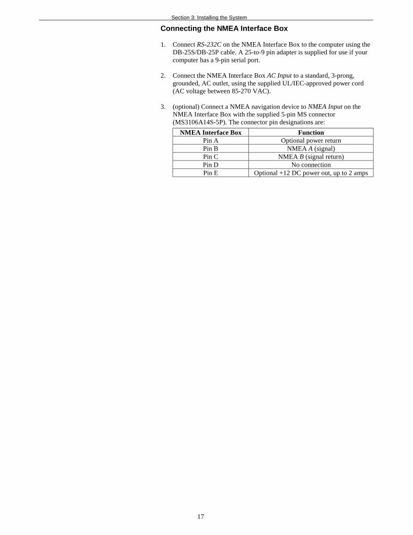
Connecting the NMEA Interface Box
1. Connect RS-232C on the NMEA Interface Box to the computer using theDB-25S/DB-25P cable. A 25-to-9 pin adapter is supplied for use if yourcomputer has a 9-pin serial port.
2. Connect the NMEA Interface Box AC Input to a standard, 3-prong,grounded, AC outlet, using the supplied UL/IEC-approved power cord(AC voltage between 85-270 VAC).
3. (optional) Connect a NMEA navigation device to NMEA Input on theNMEA Interface Box with the supplied 5-pin MS connector(MS3106A14S-5P). The connector pin designations are:
NMEA Interface Box FunctionPin A Optional power returnPin B NMEA A (signal)Pin C NMEA B (signal return)Pin D No connectionPin E Optional +12 DC power out, up to 2 amps
Section 4: Setting Up the SBE 21
18
Section 4: Setting Up the SBE 21This section describes:• Setting communications parameters with the NMEA Interface Box
dip switch• Testing power and communications and setting up the SBE 21
in SEATERM• Setting up the configuration (.con) file in SEASAVE• Command descriptions• Data output format
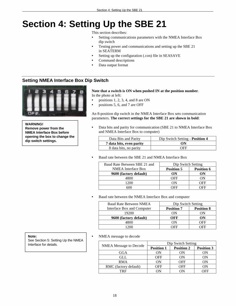
Setting NMEA Interface Box Dip Switch
Note that a switch is ON when pushed IN at the position number.In the photo at left:• positions 1, 2, 3, 4, and 8 are ON• positions 5, 6, and 7 are OFF
An 8-position dip switch in the NMEA Interface Box sets communicationparameters. The correct settings for the SBE 21 are shown in bold:
• Data bits and parity for communication (SBE 21 to NMEA Interface Boxand NMEA Interface Box to computer)
Data Bits and Parity Dip Switch Setting - Position 47 data bits, even parity ON
8 data bits, no parity OFF
• Baud rate between the SBE 21 and NMEA Interface Box
Dip Switch SettingBaud Rate Between SBE 21 andNMEA Interface Box Position 5 Position 6
9600 (factory default) ON ON4800 OFF ON1200 ON OFF600 OFF OFF
• Baud rate between the NMEA Interface Box and computer
Dip Switch SettingBaud Rate Between NMEAInterface Box and Computer Position 7 Position 8
19200 ON ON9600 (factory default) OFF ON
4800 ON OFF1200 OFF OFF
• NMEA message to decode
Dip Switch SettingNMEA Message to Decode
Position 1 Position 2 Position 3GGA ON ON ONGLL OFF ON ONRMA ON OFF ON
RMC (factory default) OFF OFF ONTRF ON ON OFF
Note:See Section 5: Setting Up the NMEAInterface for details.
WARNING!Remove power from theNMEA Interface Box beforeopening the box to change thedip switch settings.
Section 4: Setting Up the SBE 21
19
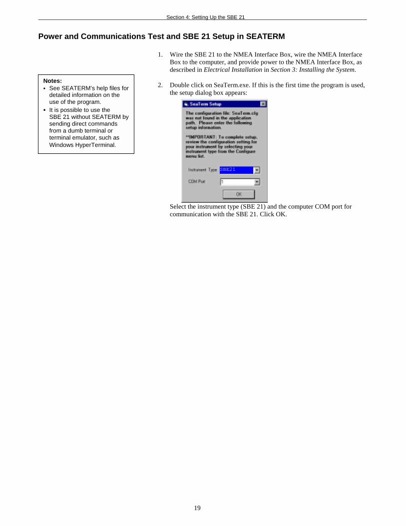
Power and Communications Test and SBE 21 Setup in SEATERM
1. Wire the SBE 21 to the NMEA Interface Box, wire the NMEA InterfaceBox to the computer, and provide power to the NMEA Interface Box, asdescribed in Electrical Installation in Section 3: Installing the System.
2. Double click on SeaTerm.exe. If this is the first time the program is used,the setup dialog box appears:
Select the instrument type (SBE 21) and the computer COM port forcommunication with the SBE 21. Click OK.
Notes:• See SEATERM’s help files for
detailed information on theuse of the program.
• It is possible to use theSBE 21 without SEATERM bysending direct commandsfrom a dumb terminal orterminal emulator, such asWindows HyperTerminal.
SBE21
Section 4: Setting Up the SBE 21
20
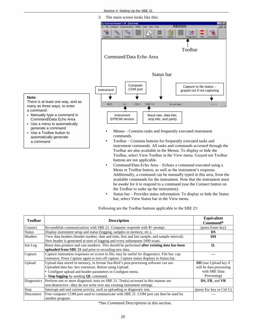
3. The main screen looks like this:
• Menus – Contains tasks and frequently executed instrumentcommands.
• Toolbar – Contains buttons for frequently executed tasks andinstrument commands. All tasks and commands accessed through theToolbar are also available in the Menus. To display or hide theToolbar, select View Toolbar in the View menu. Grayed out Toolbarbuttons are not applicable.
• Command/Data Echo Area – Echoes a command executed using aMenu or Toolbar button, as well as the instrument’s response.Additionally, a command can be manually typed in this area, from theavailable commands for the instrument. Note that the instrument mustbe awake for it to respond to a command (use the Connect button onthe Toolbar to wake up the instrument).
• Status bar – Provides status information. To display or hide the Statusbar, select View Status bar in the View menu.
Following are the Toolbar buttons applicable to the SBE 21:
Toolbar DescriptionEquivalentCommand*
Connect Re-establish communications with SBE 21. Computer responds with S> prompt. (press Enter key)Status Display instrument setup and status (logging, samples in memory, etc.). DSHeaders View data headers (header number, date and time, first and last sample, and sample interval).
New header is generated at start of logging and every subsequent 1000 scans.DH
Init Log Reset data pointers and cast numbers. This should be performed after existing data has beenuploaded from SBE 21 and prior to recording new data.
IL
Capture Capture instrument responses on screen to file; may be useful for diagnostics. File has .capextension. Press Capture again to turn off capture. Capture status displays in Status bar.
—
Upload Upload data stored in memory, in format Sea-Bird’s post-processing software can use.Uploaded data has .hex extension. Before using Upload:• Configure upload and header parameters in Configure menu.• Stop logging by sending QL command.
DD (use Upload key ifwill be data processing
with SBE DataProcessing)
Diagnostics Perform one or more diagnostic tests on SBE 21. Test(s) accessed in this manner arenon-destructive –they do not write over any existing instrument settings.
DS, FR, and VR
Stop Interrupt and end current activity, such as uploading or diagnostic test. (press Esc key or Ctrl C)Disconnect Free computer COM port used to communicate with SBE 21. COM port can then be used by
another program.—
*See Command Descriptions in this section.
Note:There is at least one way, and asmany as three ways, to entera command:• Manually type a command in
Command/Data Echo Area• Use a menu to automatically
generate a command• Use a Toolbar button to
automatically generatea command
Status bar
Menus
Command/Data Echo Area
Toolbar
InstrumentComputerCOM port
InstrumentEPROM version
Baud rate, data bits,stop bits, and parity
Capture to file status –grayed out if not capturing
Section 4: Setting Up the SBE 21
21
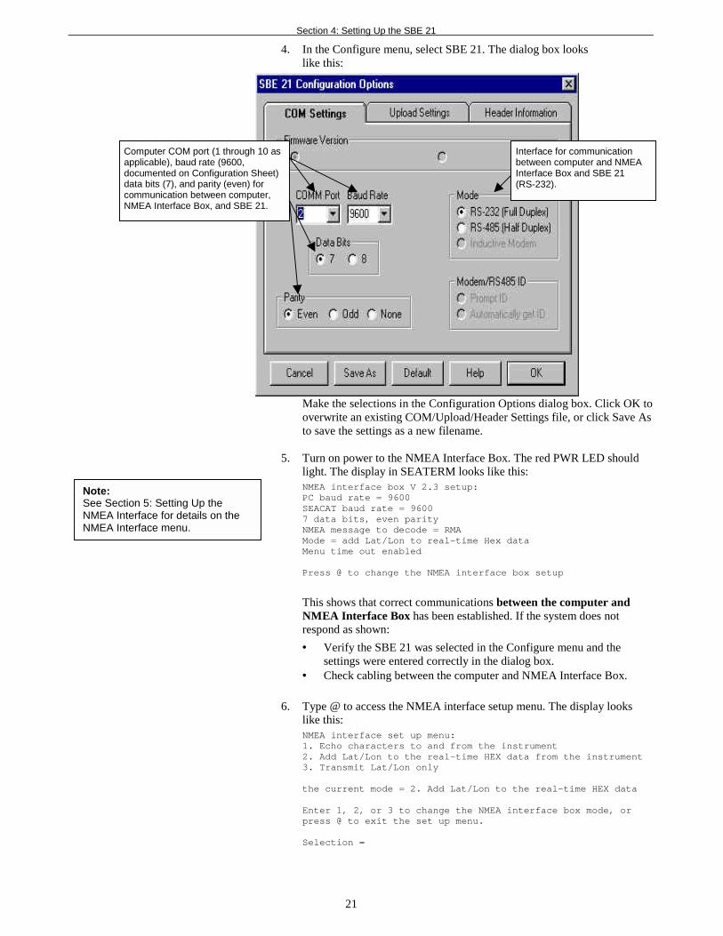
4. In the Configure menu, select SBE 21. The dialog box lookslike this:
Make the selections in the Configuration Options dialog box. Click OK tooverwrite an existing COM/Upload/Header Settings file, or click Save Asto save the settings as a new filename.
5. Turn on power to the NMEA Interface Box. The red PWR LED shouldlight. The display in SEATERM looks like this:NMEA interface box V 2.3 setup:PC baud rate = 9600SEACAT baud rate = 96007 data bits, even parityNMEA message to decode = RMAMode = add Lat/Lon to real-time Hex dataMenu time out enabled
Press @ to change the NMEA interface box setup
This shows that correct communications between the computer andNMEA Interface Box has been established. If the system does notrespond as shown:
• Verify the SBE 21 was selected in the Configure menu and thesettings were entered correctly in the dialog box.
• Check cabling between the computer and NMEA Interface Box.
6. Type @ to access the NMEA interface setup menu. The display lookslike this:NMEA interface set up menu:1. Echo characters to and from the instrument2. Add Lat/Lon to the real-time HEX data from the instrument3. Transmit Lat/Lon only
the current mode = 2. Add Lat/Lon to the real-time HEX data
Enter 1, 2, or 3 to change the NMEA interface box mode, orpress @ to exit the set up menu.
Selection =
Computer COM port (1 through 10 asapplicable), baud rate (9600,documented on Configuration Sheet)data bits (7), and parity (even) forcommunication between computer,NMEA Interface Box, and SBE 21.
Interface for communicationbetween computer and NMEAInterface Box and SBE 21(RS-232).
Note:See Section 5: Setting Up theNMEA Interface for details on theNMEA Interface menu.
Section 4: Setting Up the SBE 21
22
7. Type 1 and press the Enter key. The display then shows the current modeas 1. Echo characters to and from the instrument, which is the moderequired for communicating with the SBE 21 to set it up.
8. Type @ to exit the setup menu.
9. Click the Connect button on the Toolbar. The display looks like this:S>*ds
SC21, 3164, 4.0b, 206, 1, 6, N
S>
The first two lines are a factory-diagnostic status command and reply(reply indicates instrument serial number, firmware version, etc.).The S> shows that correct communications between the computerand SBE 21 (through the NMEA Interface Box) have beenestablished. If the system does not respond as shown:• Click the Connect button again.• Verify the correct instrument was selected in the Configure menu and
the settings were entered correctly in the Configuration Optionsdialog box. The baud rate is documented on the instrumentConfiguration Sheet.
• Check cabling between the computer, NMEA Interface Box, andSBE 21.
10. Display SBE 21 status information by clicking the Status button on theToolbar. The display looks like this:SEACAT THERMOSALINOGRAPH V4.0b SERIAL NO. 3166 01/15/2002 14:23:14ioper = 50.7 ma, vmain = 11.4, vlith = 8.8samples = 0, free = 1396736sample interval = 5 secondssample external SBE 38 temperature sensorno. of volts sampled = 0output format = SBE21start sampling when power on = nologging data = novoltage cutoff = 7.5 volts
11. Command the SBE 21 to take a sample by typing TS and pressing theEnter key. The display looks like this (if output format=SBE 21, numberof volts sampled=0, and no external temperature sensor):
78610428
where 7861 = raw Hex temperature data0428 = raw Hex conductivity data
See Data Output Formats in this section to interpret the data anddetermine if they are reasonable (i.e., room temperature andzero conductivity if running in air, or expected temperature andconductivity for water).
12. Set up the SBE 21 as desired. See Command Descriptions in this sectionfor details.
13. Command the SBE 21 to go to sleep (quiescent state) by typing QS andpressing the Enter key.
14. Turn off power to the NMEA Interface Box.
Section 4: Setting Up the SBE 21
23
Command Descriptions
This section describes commands in detail and provides examples of their use.See Appendix III: Command Summary for a summarized command list.
Commands are entered in SEATERM. When entering commands:
• Input commands in upper or lower case letters and register commands bypressing the Enter key.
• The SBE 21 sends ? CMD if an invalid command is entered.
• If the system does not return an S> prompt after executing a command,press the Enter key to get the S> prompt.
• If in quiescent state, re-establish communications by pressing Connect onthe Toolbar or the Enter key to get an S> prompt.
• If the SBE 21 is transmitting data and you want to stop it, press theEsc key or Stop on the Toolbar (or type ^C). Then press the Enter key toget the S> prompt. Note that this does not stop logging that is in progress,but allows you to enter a limited number of commands (DS, SS, TS, QL,and QS can be entered while logging).
• The SBE 21 cannot have samples with different scan lengths (more orfewer data fields per sample) in memory. If the scan length is changed bycommanding it to add or subtract a data field (such as an external voltage),the SBE 21 must initialize logging. Initializing logging sets the samplenumber and header number to 0, so the entire memory is available forrecording data with the new scan length. Initializing logging should onlybe performed after all previous data has been uploaded. Therefore,commands that change the scan length (SVx, SBE38=, and SBE3=)prompt the user for verification before executing, to prevent accidentaloverwriting of existing data.
Entries made with the commands are permanently stored in the SBE 21 andremain in effect until you change them.
• The only exception occurs if J1 is removed from the Power PCB (topboard in PCB assembly) to replace the back-up lithium battery or to do areset of the instrument. Upon reassembly, set the date and time (ST) andinitialize logging (IL).(See Appendix II: Electronics Disassembly/Reassembly for details onaccessing the PCBs. See Section 8: Troubleshooting for details onperforming a reset of the instrument.)
Section 4: Setting Up the SBE 21
24
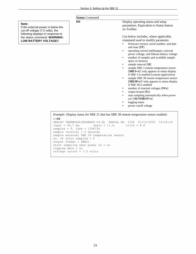
Status CommandDS Display operating status and setup
parameters. Equivalent to Status buttonon Toolbar.
List below includes, where applicable,command used to modify parameter.• firmware version, serial number, and date
and time [ST]• operating current (milliamps), external
power voltage, and lithium battery voltage• number of samples and available sample
space in memory• sample interval [SI]• sample SBE 3 remote temperature sensor
[SBE3=x]? only appears in status displayif SBE 3 is enabled (custom application)
• sample SBE 38 remote temperature sensor[SBE38=x]? only appears in status displayif SBE 38 is enabled
• number of external voltages [SVx]• output format [Fx]• start sampling automatically when power
on? [AUTORUN=x]• logging status• power cutoff voltage
Example: Display status for SBE 21 that has SBE 38 remote temperature sensor enabled.S>DSSEACAT THERMOSALINOGRAPH V4.0b SERIAL NO. 3166 01/15/2002 14:23:14ioper = 50.7 ma, vmain = 11.4, vlith = 8.8samples = 0, free = 1396736sample interval = 5 secondssample external SBE 38 temperature sensorno. of volts sampled = 0output format = SBE21start sampling when power on = nologging data = novoltage cutoff = 7.5 volts
Note:If the external power is below thecut-off voltage (7.5 volts), thefollowing displays in response tothe status command: WARNING:LOW BATTERY VOLTAGE!!
Section 4: Setting Up the SBE 21
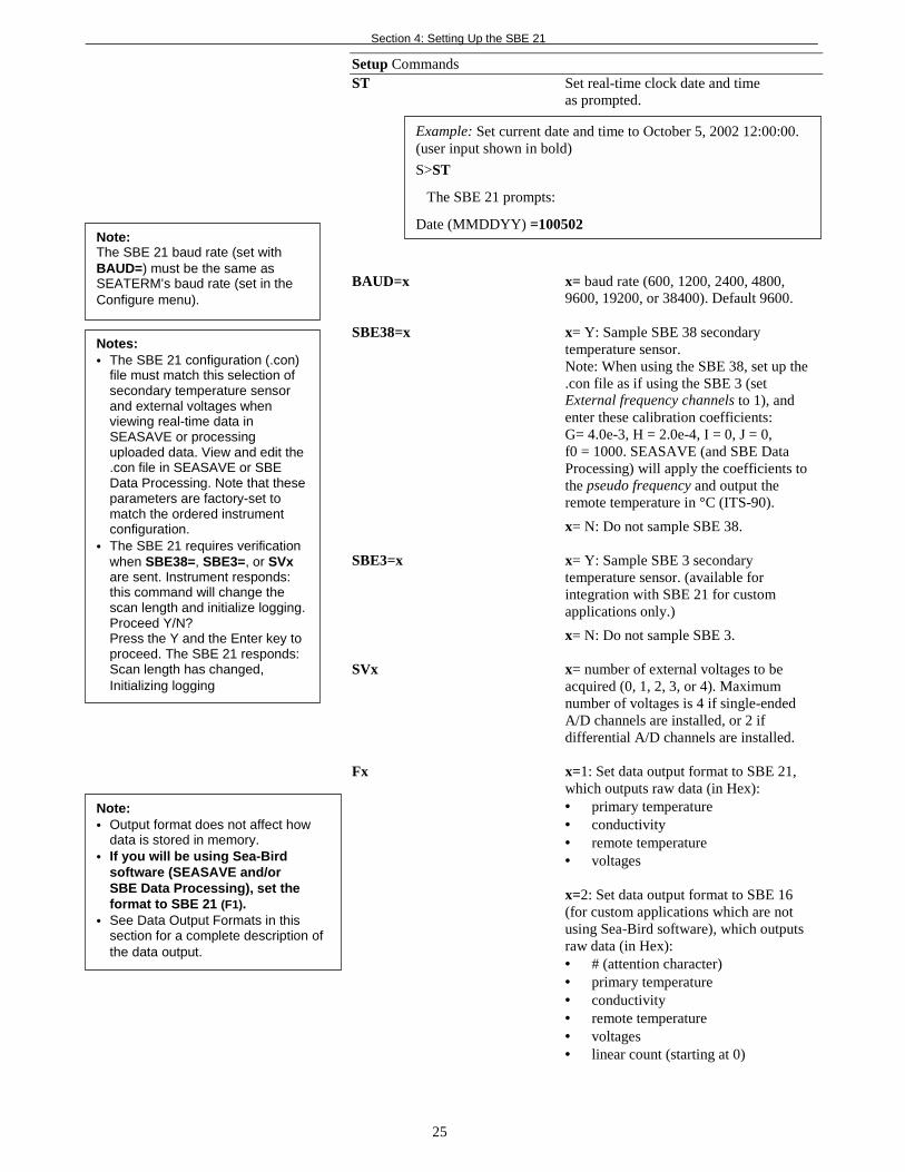
Setup CommandsST Set real-time clock date and time
as prompted.
BAUD=x
SBE38=x
SBE3=x
SVx
Fx
Note:The SBE 21 baud rate (set withBAUD=) must be the same asSEATERM’s baud rate (set in theConfigure menu).
Notes:• The SBE 21 configuration (.con)
file must match this selection ofsecondary temperature sensorand external voltages whenviewing real-time data inSEASAVE or processinguploaded data. View and edit the.con file in SEASAVE or SBEData Processing. Note that theseparameters are factory-set tomatch the ordered instrumentconfiguration.
• The SBE 21 requires verificationwhen SBE38=, SBE3=, or SVxare sent. Instrument responds:this command will change thescan length and initialize logging.Proceed Y/N?Press the Y and the Enter key toproceed. The SBE 21 responds:Scan length has changed,Initializing logging
Note:• Output format does not affect how
data is stored in memory.• If you will be using Sea-Bird
software (SEASAVE and/orSBE Data Processing), set theformat to SBE 21 (F1).
• See Data Output Formats in thissection for a complete description ofthe data output.
Example: Set current date and time to October 5, 2002 12:00:00.(user input shown in bold)
S>ST
The SBE 21 prompts:
Date (MMDDYY) =100502
25
x= baud rate (600, 1200, 2400, 4800,9600, 19200, or 38400). Default 9600.
x= Y: Sample SBE 38 secondarytemperature sensor.Note: When using the SBE 38, set up the.con file as if using the SBE 3 (setExternal frequency channels to 1), andenter these calibration coefficients:G= 4.0e-3, H = 2.0e-4, I = 0, J = 0,f0 = 1000. SEASAVE (and SBE DataProcessing) will apply the coefficients tothe pseudo frequency and output theremote temperature in °C (ITS-90).
x= N: Do not sample SBE 38.
x= Y: Sample SBE 3 secondarytemperature sensor. (available forintegration with SBE 21 for customapplications only.)
x= N: Do not sample SBE 3.
x= number of external voltages to beacquired (0, 1, 2, 3, or 4). Maximumnumber of voltages is 4 if single-endedA/D channels are installed, or 2 ifdifferential A/D channels are installed.
x=1: Set data output format to SBE 21,which outputs raw data (in Hex):• primary temperature• conductivity• remote temperature• voltages
x=2: Set data output format to SBE 16(for custom applications which are notusing Sea-Bird software), which outputsraw data (in Hex):• # (attention character)• primary temperature• conductivity• remote temperature• voltages• linear count (starting at 0)
Section 4: Setting Up the SBE 21
26
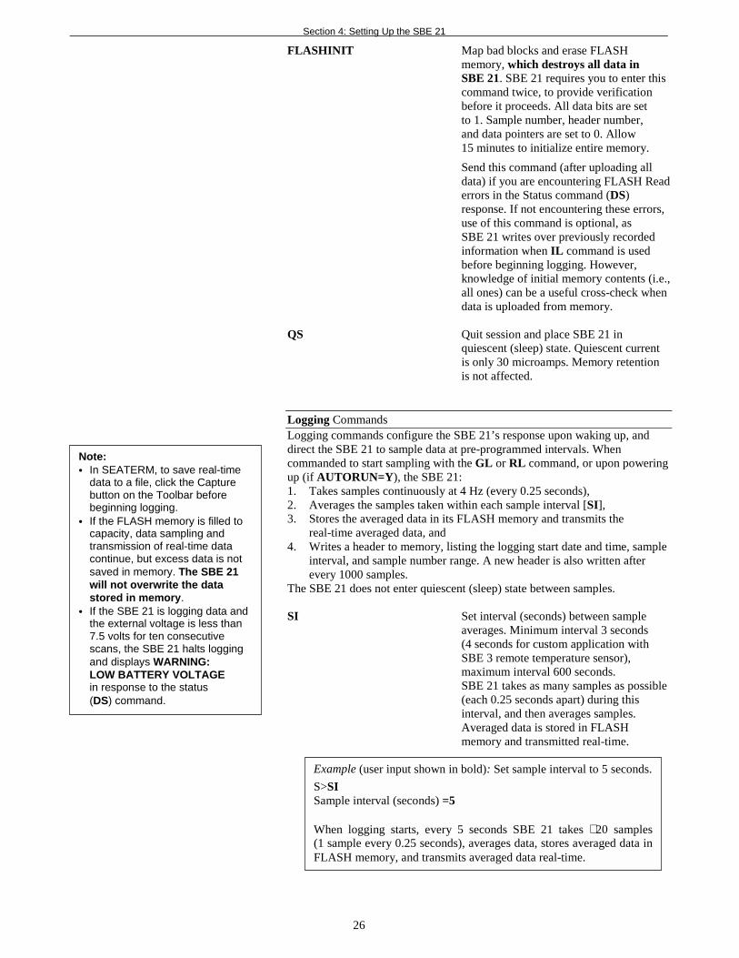
FLASHINIT Map bad blocks and erase FLASHmemory, which destroys all data inSBE 21. SBE 21 requires you to enter thiscommand twice, to provide verificationbefore it proceeds. All data bits are setto 1. Sample number, header number,and data pointers are set to 0. Allow15 minutes to initialize entire memory.
Send this command (after uploading alldata) if you are encountering FLASH Readerrors in the Status command (DS)response. If not encountering these errors,use of this command is optional, asSBE 21 writes over previously recordedinformation when IL command is usedbefore beginning logging. However,knowledge of initial memory contents (i.e.,all ones) can be a useful cross-check whendata is uploaded from memory.
QS Quit session and place SBE 21 inquiescent (sleep) state. Quiescent currentis only 30 microamps. Memory retentionis not affected.
Logging CommandsLogging commands configure the SBE 21’s response upon waking up, anddirect the SBE 21 to sample data at pre-programmed intervals. Whencommanded to start sampling with the GL or RL command, or upon poweringup (if AUTORUN=Y), the SBE 21:1. Takes samples continuously at 4 Hz (every 0.25 seconds),2. Averages the samples taken within each sample interval [SI],3. Stores the averaged data in its FLASH memory and transmits the
real-time averaged data, and4. Writes a header to memory, listing the logging start date and time, sample
interval, and sample number range. A new header is also written afterevery 1000 samples.
The SBE 21 does not enter quiescent (sleep) state between samples.
SI Set interval (seconds) between sampleaverages. Minimum interval 3 seconds(4 seconds for custom application withSBE 3 remote temperature sensor),maximum interval 600 seconds.SBE 21 takes as many samples as possible(each 0.25 seconds apart) during thisinterval, and then averages samples.Averaged data is stored in FLASHmemory and transmitted real-time.
Note:• In SEATERM, to save real-time
data to a file, click the Capturebutton on the Toolbar beforebeginning logging.
• If the FLASH memory is filled tocapacity, data sampling andtransmission of real-time datacontinue, but excess data is notsaved in memory. The SBE 21will not overwrite the datastored in memory.
• If the SBE 21 is logging data andthe external voltage is less than7.5 volts for ten consecutivescans, the SBE 21 halts loggingand displays WARNING:LOW BATTERY VOLTAGEin response to the status(DS) command.
Example (user input shown in bold): Set sample interval to 5 seconds.
S>SISample interval (seconds) =5
When logging starts, every 5 seconds SBE 21 takes ∼ 20 samples(1 sample every 0.25 seconds), averages data, stores averaged data inFLASH memory, and transmits averaged data real-time.
Section 4: Setting Up the SBE 21
27
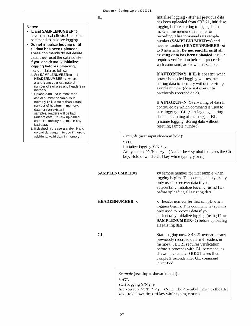
IL Initialize logging - after all previous datahas been uploaded from SBE 21, initializelogging before starting to log again tomake entire memory available forrecording. This command sets samplenumber (SAMPLENUMBER=x) andheader number (HEADERNUMBER=x)to 0 internally. Do not send IL until allexisting data has been uploaded. SBE 21requires verification before it proceedswith command, as shown in example.
If AUTORUN=Y: If IL is not sent, whenpower is applied logging will resumestoring data to memory without resettingsample number (does not overwritepreviously recorded data).
If AUTORUN=N: Overwriting of data iscontrolled by which command is used tostart logging - GL (start logging, storingdata at beginning of memory) or RL(resume logging, storing data withoutresetting sample number).
SAMPLENUMBER=x x= sample number for first sample whenlogging begins. This command is typicallyonly used to recover data if youaccidentally initialize logging (using IL)before uploading all existing data.
HEADERNUMBER=x x= header number for first sample whenlogging begins. This command is typicallyonly used to recover data if youaccidentally initialize logging (using IL orSAMPLENUMBER=0) before uploadingall existing data.
GL Start logging now. SBE 21 overwrites anypreviously recorded data and headers inmemory. SBE 21 requires verificationbefore it proceeds with GL command, asshown in example. SBE 21 takes firstsample 3 seconds after GL commandis verified.
Notes:• IL and SAMPLENUMBER=0
have identical effects. Use eithercommand to initialize logging.
• Do not initialize logging untilall data has been uploaded.These commands do not deletedata; they reset the data pointer.If you accidentally initializelogging before uploading,recover data as follows:1. Set SAMPLENUMBER=a and
HEADERNUMBER=b, wherea and b are your estimate ofnumber of samples and headers inmemory.
2. Upload data. If a is more thanactual number of samples inmemory or b is more than actualnumber of headers in memory,data for non-existentsamples/headers will be bad,random data. Review uploadeddata file carefully and delete anybad data.
3. If desired, increase a and/or b andupload data again, to see if there isadditional valid data in memory. Example (user input shown in bold):
S>ILInitialize logging Y/N ? yAre you sure ^Y/N ? ^y (Note: The ^ symbol indicates the Ctrlkey. Hold down the Ctrl key while typing y or n.)
Example (user input shown in bold):
S>GLStart logging Y/N ? yAre you sure ^Y/N ? ^y (Note: The ^ symbol indicates the Ctrlkey. Hold down the Ctrl key while typing y or n.)
Section 4: Setting Up the SBE 21
28
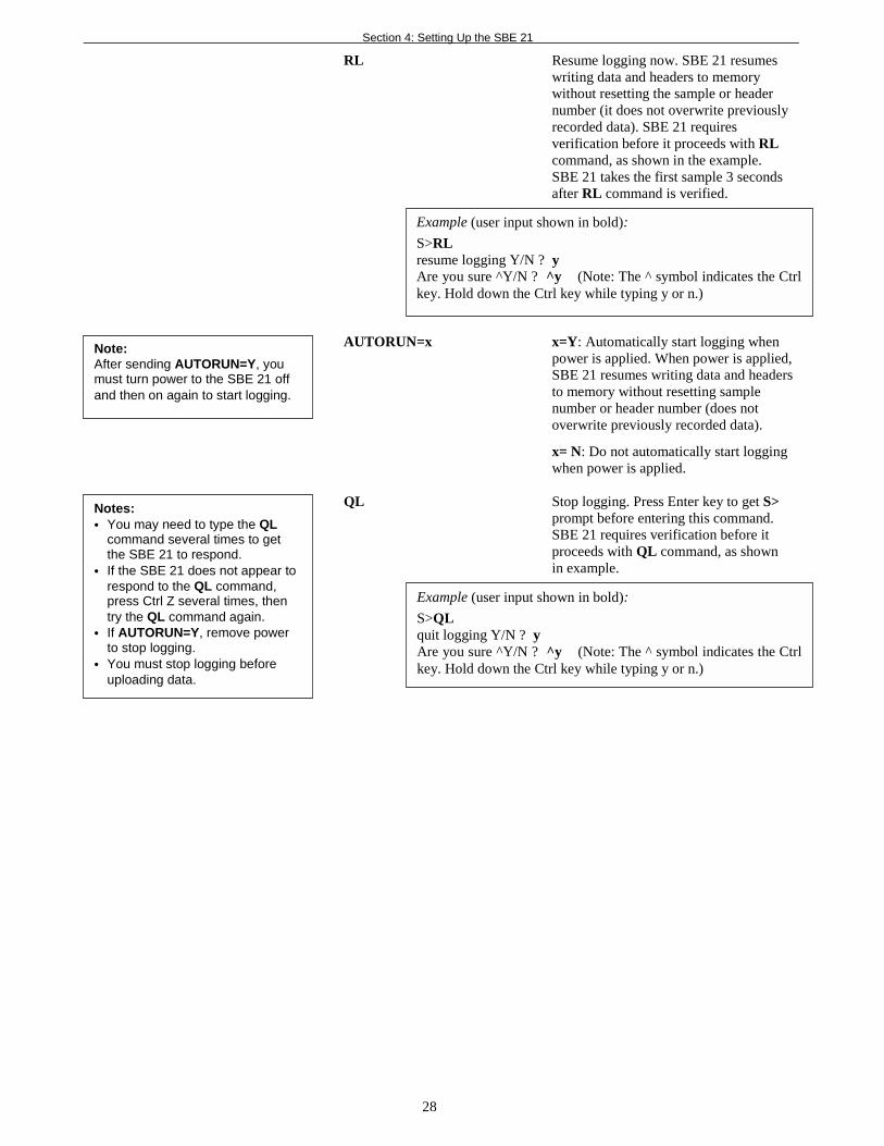
RL Resume logging now. SBE 21 resumeswriting data and headers to memorywithout resetting the sample or headernumber (it does not overwrite previouslyrecorded data). SBE 21 requiresverification before it proceeds with RLcommand, as shown in the example.SBE 21 takes the first sample 3 secondsafter RL command is verified.
AUTORUN=x x=Y: Automatically start logging whenpower is applied. When power is applied,SBE 21 resumes writing data and headersto memory without resetting samplenumber or header number (does notoverwrite previously recorded data).
x= N: Do not automatically start loggingwhen power is applied.
QL Stop logging. Press Enter key to get S>prompt before entering this command.SBE 21 requires verification before itproceeds with QL command, as shownin example.
Example (user input shown in bold):
S>RLresume logging Y/N ? yAre you sure ^Y/N ? ^y (Note: The ^ symbol indicates the Ctrlkey. Hold down the Ctrl key while typing y or n.)
Notes:• You may need to type the QL
command several times to getthe SBE 21 to respond.
• If the SBE 21 does not appear torespond to the QL command,press Ctrl Z several times, thentry the QL command again.
• If AUTORUN=Y, remove powerto stop logging.
• You must stop logging beforeuploading data.
Example (user input shown in bold):
S>QLquit logging Y/N ? yAre you sure ^Y/N ? ^y (Note: The ^ symbol indicates the Ctrlkey. Hold down the Ctrl key while typing y or n.)
Note:After sending AUTORUN=Y, youmust turn power to the SBE 21 offand then on again to start logging.
Section 4: Setting Up the SBE 21
29
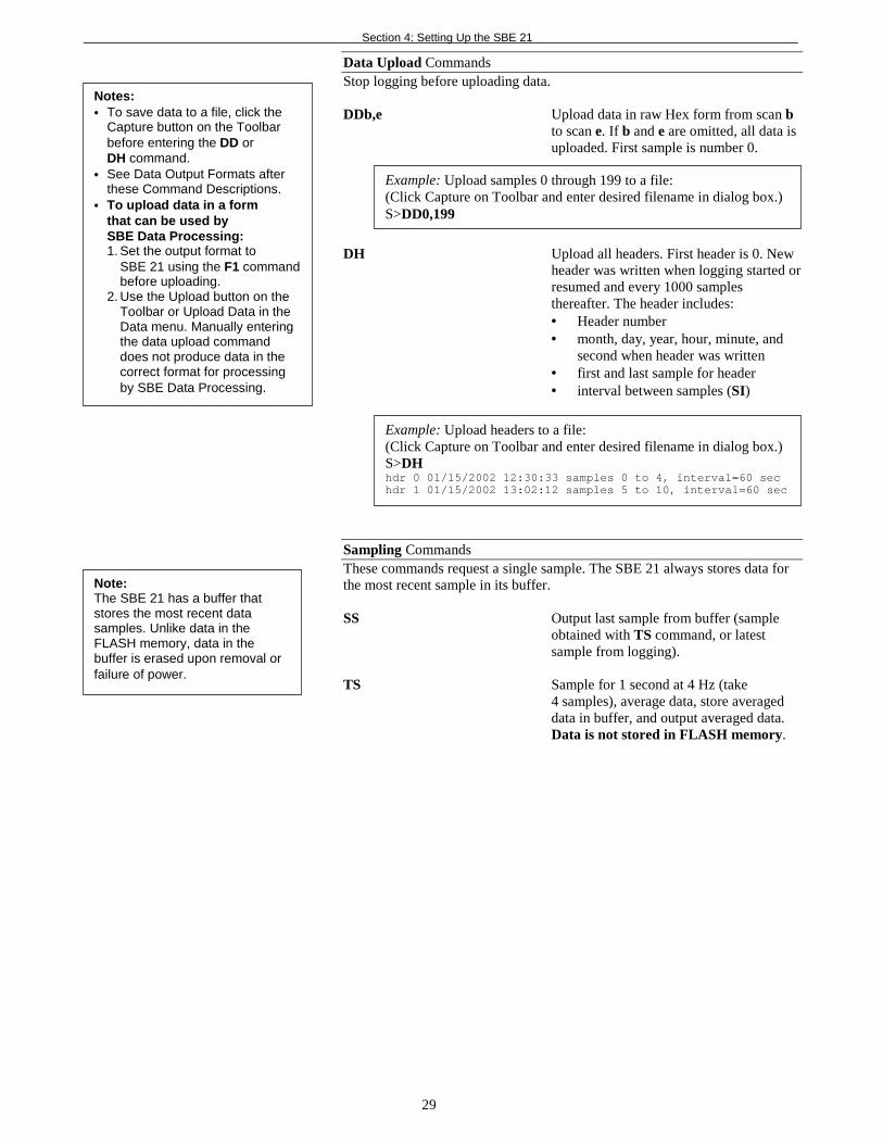
Data Upload CommandsStop logging before uploading data.
DDb,e Upload data in raw Hex form from scan bto scan e. If b and e are omitted, all data isuploaded. First sample is number 0.
DH Upload all headers. First header is 0. Newheader was written when logging started orresumed and every 1000 samplesthereafter. The header includes:• Header number• month, day, year, hour, minute, and
second when header was written• first and last sample for header• interval between samples (SI)
Sampling CommandsThese commands request a single sample. The SBE 21 always stores data forthe most recent sample in its buffer.
SS Output last sample from buffer (sampleobtained with TS command, or latestsample from logging).
TS Sample for 1 second at 4 Hz (take4 samples), average data, store averageddata in buffer, and output averaged data.Data is not stored in FLASH memory.
Note:The SBE 21 has a buffer thatstores the most recent datasamples. Unlike data in theFLASH memory, data in thebuffer is erased upon removal orfailure of power.
Example: Upload samples 0 through 199 to a file:(Click Capture on Toolbar and enter desired filename in dialog box.)S>DD0,199
Notes:• To save data to a file, click the
Capture button on the Toolbarbefore entering the DD orDH command.
• See Data Output Formats afterthese Command Descriptions.
• To upload data in a formthat can be used bySBE Data Processing:1. Set the output format to
SBE 21 using the F1 commandbefore uploading.
2. Use the Upload button on theToolbar or Upload Data in theData menu. Manually enteringthe data upload commanddoes not produce data in thecorrect format for processingby SBE Data Processing.
Example: Upload headers to a file:(Click Capture on Toolbar and enter desired filename in dialog box.)S>DHhdr 0 01/15/2002 12:30:33 samples 0 to 4, interval=60 sechdr 1 01/15/2002 13:02:12 samples 5 to 10, interval=60 sec
Section 4: Setting Up the SBE 21
30
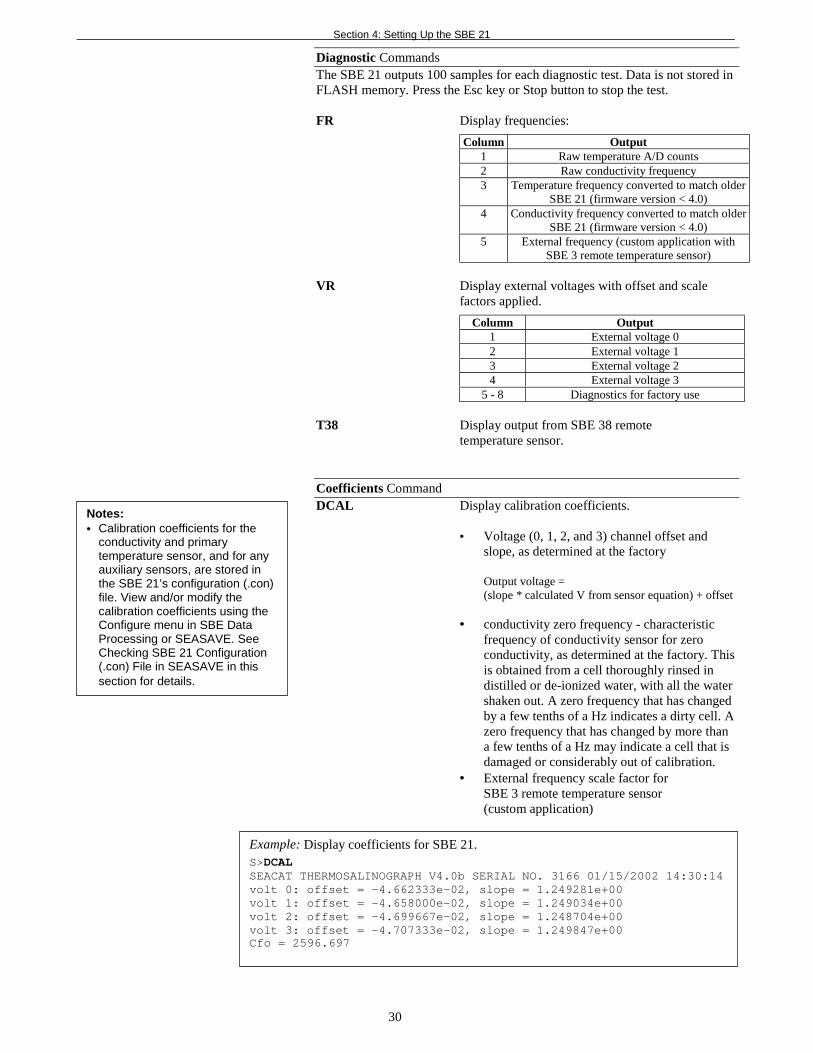
Diagnostic CommandsThe SBE 21 outputs 100 samples for each diagnostic test. Data is not stored inFLASH memory. Press the Esc key or Stop button to stop the test.
FR Display frequencies:
Column Output1 Raw temperature A/D counts2 Raw conductivity frequency3 Temperature frequency converted to match older
SBE 21 (firmware version < 4.0)4 Conductivity frequency converted to match older
SBE 21 (firmware version < 4.0)5 External frequency (custom application with
SBE 3 remote temperature sensor)
VR Display external voltages with offset and scalefactors applied.
Column Output1 External voltage 02 External voltage 13 External voltage 24 External voltage 3
5 - 8 Diagnostics for factory use
T38 Display output from SBE 38 remotetemperature sensor.
Coefficients CommandDCAL Display calibration coefficients.
• Voltage (0, 1, 2, and 3) channel offset andslope, as determined at the factory
Output voltage =(slope * calculated V from sensor equation) + offset
• conductivity zero frequency - characteristicfrequency of conductivity sensor for zeroconductivity, as determined at the factory. Thisis obtained from a cell thoroughly rinsed indistilled or de-ionized water, with all the watershaken out. A zero frequency that has changedby a few tenths of a Hz indicates a dirty cell. Azero frequency that has changed by more thana few tenths of a Hz may indicate a cell that isdamaged or considerably out of calibration.
• External frequency scale factor forSBE 3 remote temperature sensor(custom application)
Example: Display coefficients for SBE 21.S>DCALSEACAT THERMOSALINOGRAPH V4.0b SERIAL NO. 3166 01/15/2002 14:30:14volt 0: offset = -4.662333e-02, slope = 1.249281e+00volt 1: offset = -4.658000e-02, slope = 1.249034e+00volt 2: offset = -4.699667e-02, slope = 1.248704e+00volt 3: offset = -4.707333e-02, slope = 1.249847e+00Cfo = 2596.697
Notes:• Calibration coefficients for the
conductivity and primarytemperature sensor, and for anyauxiliary sensors, are stored inthe SBE 21’s configuration (.con)file. View and/or modify thecalibration coefficients using theConfigure menu in SBE DataProcessing or SEASAVE. SeeChecking SBE 21 Configuration(.con) File in SEASAVE in thissection for details.
Section 4: Setting Up the SBE 21
31
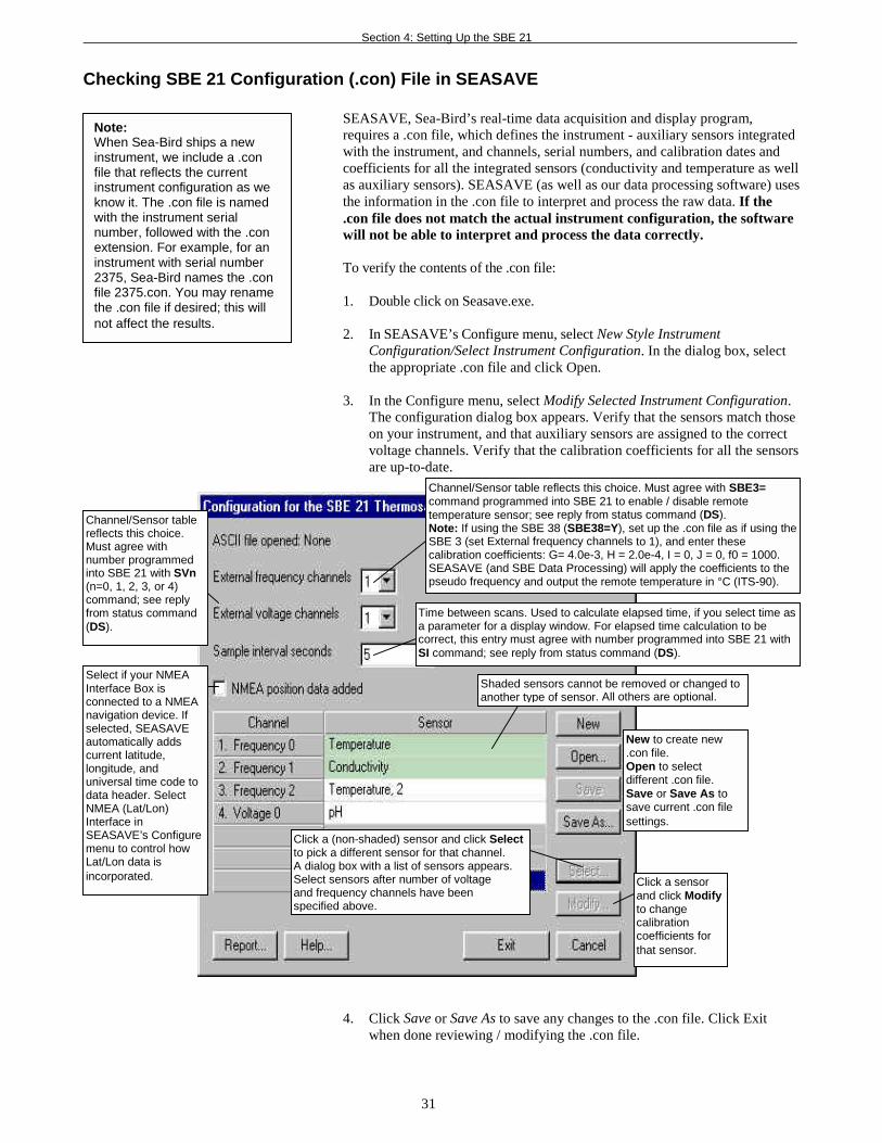
Checking SBE 21 Configuration (.con) File in SEASAVE
SEASAVE, Sea-Bird’s real-time data acquisition and display program,requires a .con file, which defines the instrument - auxiliary sensors integratedwith the instrument, and channels, serial numbers, and calibration dates andcoefficients for all the integrated sensors (conductivity and temperature as wellas auxiliary sensors). SEASAVE (as well as our data processing software) usesthe information in the .con file to interpret and process the raw data. If the.con file does not match the actual instrument configuration, the softwarewill not be able to interpret and process the data correctly.
To verify the contents of the .con file:
1. Double click on Seasave.exe.
2. In SEASAVE’s Configure menu, select New Style InstrumentConfiguration/Select Instrument Configuration. In the dialog box, selectthe appropriate .con file and click Open.
3. In the Configure menu, select Modify Selected Instrument Configuration.The configuration dialog box appears. Verify that the sensors match thoseon your instrument, and that auxiliary sensors are assigned to the correctvoltage channels. Verify that the calibration coefficients for all the sensorsare up-to-date.
4. Click Save or Save As to save any changes to the .con file. Click Exitwhen done reviewing / modifying the .con file.
Note:When Sea-Bird ships a newinstrument, we include a .confile that reflects the currentinstrument configuration as weknow it. The .con file is namedwith the instrument serialnumber, followed with the .conextension. For example, for aninstrument with serial number2375, Sea-Bird names the .confile 2375.con. You may renamethe .con file if desired; this willnot affect the results.
Channel/Sensor tablereflects this choice.Must agree withnumber programmedinto SBE 21 with SVn(n=0, 1, 2, 3, or 4)command; see replyfrom status command(DS).
Time between scans. Used to calculate elapsed time, if you select time asa parameter for a display window. For elapsed time calculation to becorrect, this entry must agree with number programmed into SBE 21 withSI command; see reply from status command (DS).
Select if your NMEAInterface Box isconnected to a NMEAnavigation device. Ifselected, SEASAVEautomatically addscurrent latitude,longitude, anduniversal time code todata header. SelectNMEA (Lat/Lon)Interface inSEASAVE’s Configuremenu to control howLat/Lon data isincorporated.
Click a (non-shaded) sensor and click Selectto pick a different sensor for that channel.A dialog box with a list of sensors appears.Select sensors after number of voltageand frequency channels have beenspecified above.
Click a sensorand click Modifyto changecalibrationcoefficients forthat sensor.
New to create new.con file.Open to selectdifferent .con file.Save or Save As tosave current .con filesettings.
Channel/Sensor table reflects this choice. Must agree with SBE3=command programmed into SBE 21 to enable / disable remotetemperature sensor; see reply from status command (DS).Note: If using the SBE 38 (SBE38=Y), set up the .con file as if using theSBE 3 (set External frequency channels to 1), and enter thesecalibration coefficients: G= 4.0e-3, H = 2.0e-4, I = 0, J = 0, f0 = 1000.SEASAVE (and SBE Data Processing) will apply the coefficients to thepseudo frequency and output the remote temperature in °C (ITS-90).
Shaded sensors cannot be removed or changed toanother type of sensor. All others are optional.

Section 4: Setting Up the SBE 21
32
Data Output FormatsThe SBE 21 outputs data in raw, hexadecimal form as described below.
The inclusion of some output parameters is dependent on the systemconfiguration - if the specified sensor is not enabled (see CommandDescriptions above), the corresponding data is not included in the output datastream, shortening the data string.
• SBE 21 Format (F1) - ttttccccrrrrrruuuvvvwwwxxx (use this format if youwill be using SEASAVE to acquire real-time data and/or SBE DataProcessing to process the data)
• SBE 16 Format (F2) - #ttttccccrrrrrruuuvvvwwwxxxnnnn
wheretttt = primary temperaturecccc = conductivityrrrrrr = remote temperature (from SBE 38 or SBE 3 remote sensor)uuu, vvv, www, xxx = voltage outputs 0, 1, 2, and 3 respectively# = attention characternnnn = lineal sample count (0, 1, 2, etc.)
Data is output in the order listed, with no spaces or commas betweenparameters. Shown with each parameter is the number of digits.
Calculation of the parameter from the data is described below (use the decimalequivalent of the hex data in the equations).1. Temperature
temperature frequency (Hz) = ( tttt / 19 ) + 21002. Conductivity
conductivity frequency (Hz) = square root [ ( cccc * 2100 ) + 6250000 ]3. SBE 3 secondary temperature (if SBE3=Y)
SBE 3 temperature frequency (Hz) = rrrrrr / 2564. SBE 38 secondary temperature (if SBE38=Y)
SBE 38 temperature psuedo frequency (Hz) = rrrrrr / 2565. External voltage 0 (if 1 or more external voltages defined with SVx)
external voltage 0 (volts) = uuu / 8196. External voltage 1 (if 2 or more external voltages defined with SVx)
external voltage 1 (volts) = vvv / 8197. External voltage 2 (if 3 or more external voltages defined with SVx)
external voltage 2 (volts) = www / 8198. External voltage 3 (if 4 external voltages defined with SVx)
external voltage 3 (volts) = xxx / 819
Example: SBE 21 with SBE 38 and two external voltages sampled,example scan = ttttccccrrrrrruuuvvv = A80603DA1B58001F5A21
• Temperature = tttt = A806 (43014 decimal);temperature frequency = (43014 / 19) + 2100 = 4363.89 Hz
• Conductivity = cccc = 03DA (986 decimal);conductivity frequency =square root [986 *2100) + 6250000] = 2884.545 Hz
• SBE 38 = rrrrrr = 1B5800 (1,792,000 decimal)temperature (Hz) = (1,792,000 / 256) = 7000 Hz
• First external voltage = uuu = 1F5 (501 decimal);voltage = 501 / 819 = 0.612 volts
• Second external voltage = vvv = A21 (2593 decimal);voltage = 2593 / 819 = 3.166 volts
Notes:• Sea-Bird’s data processing
software (SBE Data Processing)uses the equations shown toperform these calculations; it thenuses the calibration coefficients inthe configuration (.con) file toconvert the raw frequencies andvoltages to engineering units.Alternatively, you can use theequations to develop your ownprocessing software.
• If using the SBE 38, set up theSBE 21 .con file as if using theSBE 3 (set External frequencychannels to 1), and enter thefollowing values for the calibrationcoefficients: G= 4.0e-3, H = 2.0e-4,I = 0, J = 0, f0 = 1000.SEASAVE and SBE DataProcessing will apply thecoefficients to the pseudofrequency and output the remotetemperature in °C (ITS-90).
Note:SBE 21 always outputs an evennumber of voltage characters. If youenable 1 or 3 voltages, it adds a 0 tothe data stream before the lastvoltage, as shown below:• 1 voltage enabled -
ttttccccrrrrrr0uuu or#ttttccccrrrrrr0uuunnnn
• 3 voltages enabled -ttttccccrrrrrruuuvvv0www#ttttccccrrrrrruuuvvv0wwwnnnn
Section 5: Setting Up the NMEA Interface
33
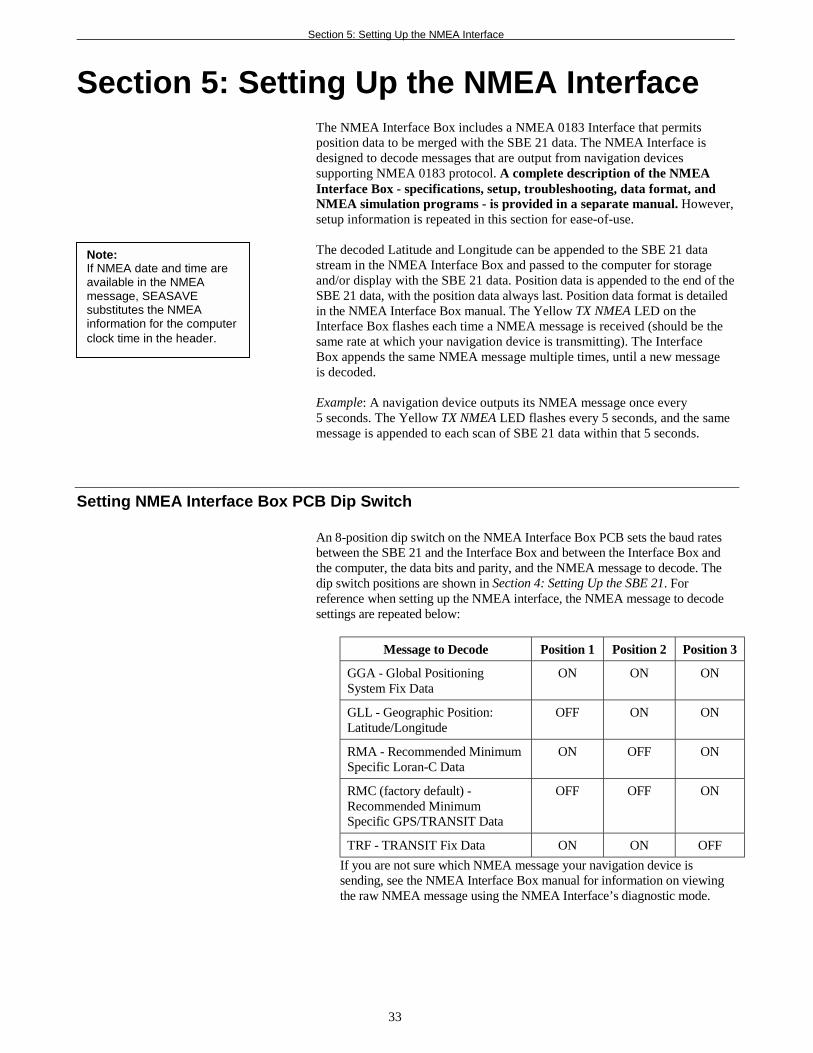
Section 5: Setting Up the NMEA InterfaceThe NMEA Interface Box includes a NMEA 0183 Interface that permitsposition data to be merged with the SBE 21 data. The NMEA Interface isdesigned to decode messages that are output from navigation devicessupporting NMEA 0183 protocol. A complete description of the NMEAInterface Box - specifications, setup, troubleshooting, data format, andNMEA simulation programs - is provided in a separate manual. However,setup information is repeated in this section for ease-of-use.
The decoded Latitude and Longitude can be appended to the SBE 21 datastream in the NMEA Interface Box and passed to the computer for storageand/or display with the SBE 21 data. Position data is appended to the end of theSBE 21 data, with the position data always last. Position data format is detailedin the NMEA Interface Box manual. The Yellow TX NMEA LED on theInterface Box flashes each time a NMEA message is received (should be thesame rate at which your navigation device is transmitting). The InterfaceBox appends the same NMEA message multiple times, until a new messageis decoded.
Example: A navigation device outputs its NMEA message once every5 seconds. The Yellow TX NMEA LED flashes every 5 seconds, and the samemessage is appended to each scan of SBE 21 data within that 5 seconds.
Setting NMEA Interface Box PCB Dip Switch
An 8-position dip switch on the NMEA Interface Box PCB sets the baud ratesbetween the SBE 21 and the Interface Box and between the Interface Box andthe computer, the data bits and parity, and the NMEA message to decode. Thedip switch positions are shown in Section 4: Setting Up the SBE 21. Forreference when setting up the NMEA interface, the NMEA message to decodesettings are repeated below:
Message to Decode Position 1 Position 2 Position 3
GGA - Global PositioningSystem Fix Data
ON ON ON
GLL - Geographic Position:Latitude/Longitude
OFF ON ON
RMA - Recommended MinimumSpecific Loran-C Data
ON OFF ON
RMC (factory default) -Recommended MinimumSpecific GPS/TRANSIT Data
OFF OFF ON
TRF - TRANSIT Fix Data ON ON OFF
If you are not sure which NMEA message your navigation device issending, see the NMEA Interface Box manual for information on viewingthe raw NMEA message using the NMEA Interface’s diagnostic mode.
Note:If NMEA date and time areavailable in the NMEAmessage, SEASAVEsubstitutes the NMEAinformation for the computerclock time in the header.
Section 5: Setting Up the NMEA Interface
34
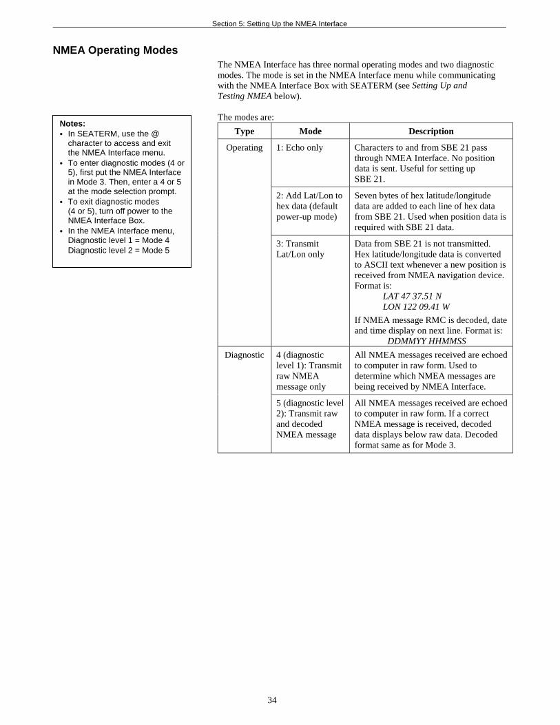
NMEA Operating Modes The NMEA Interface has three normal operating modes and two diagnosticmodes. The mode is set in the NMEA Interface menu while communicatingwith the NMEA Interface Box with SEATERM (see Setting Up andTesting NMEA below).
The modes are:
Type Mode Description
1: Echo only Characters to and from SBE 21 passthrough NMEA Interface. No positiondata is sent. Useful for setting upSBE 21.
2: Add Lat/Lon tohex data (defaultpower-up mode)
Seven bytes of hex latitude/longitudedata are added to each line of hex datafrom SBE 21. Used when position data isrequired with SBE 21 data.
Operating
3: TransmitLat/Lon only
Data from SBE 21 is not transmitted.Hex latitude/longitude data is convertedto ASCII text whenever a new position isreceived from NMEA navigation device.Format is:
LAT 47 37.51 NLON 122 09.41 W
If NMEA message RMC is decoded, dateand time display on next line. Format is:
DDMMYY HHMMSS
4 (diagnosticlevel 1): Transmitraw NMEAmessage only
All NMEA messages received are echoedto computer in raw form. Used todetermine which NMEA messages arebeing received by NMEA Interface.
Diagnostic
5 (diagnostic level2): Transmit rawand decodedNMEA message
All NMEA messages received are echoedto computer in raw form. If a correctNMEA message is received, decodeddata displays below raw data. Decodedformat same as for Mode 3.
Notes:• In SEATERM, use the @
character to access and exitthe NMEA Interface menu.
• To enter diagnostic modes (4 or5), first put the NMEA Interfacein Mode 3. Then, enter a 4 or 5at the mode selection prompt.
• To exit diagnostic modes(4 or 5), turn off power to theNMEA Interface Box.
• In the NMEA Interface menu,Diagnostic level 1 = Mode 4Diagnostic level 2 = Mode 5
Section 5: Setting Up the NMEA Interface
35
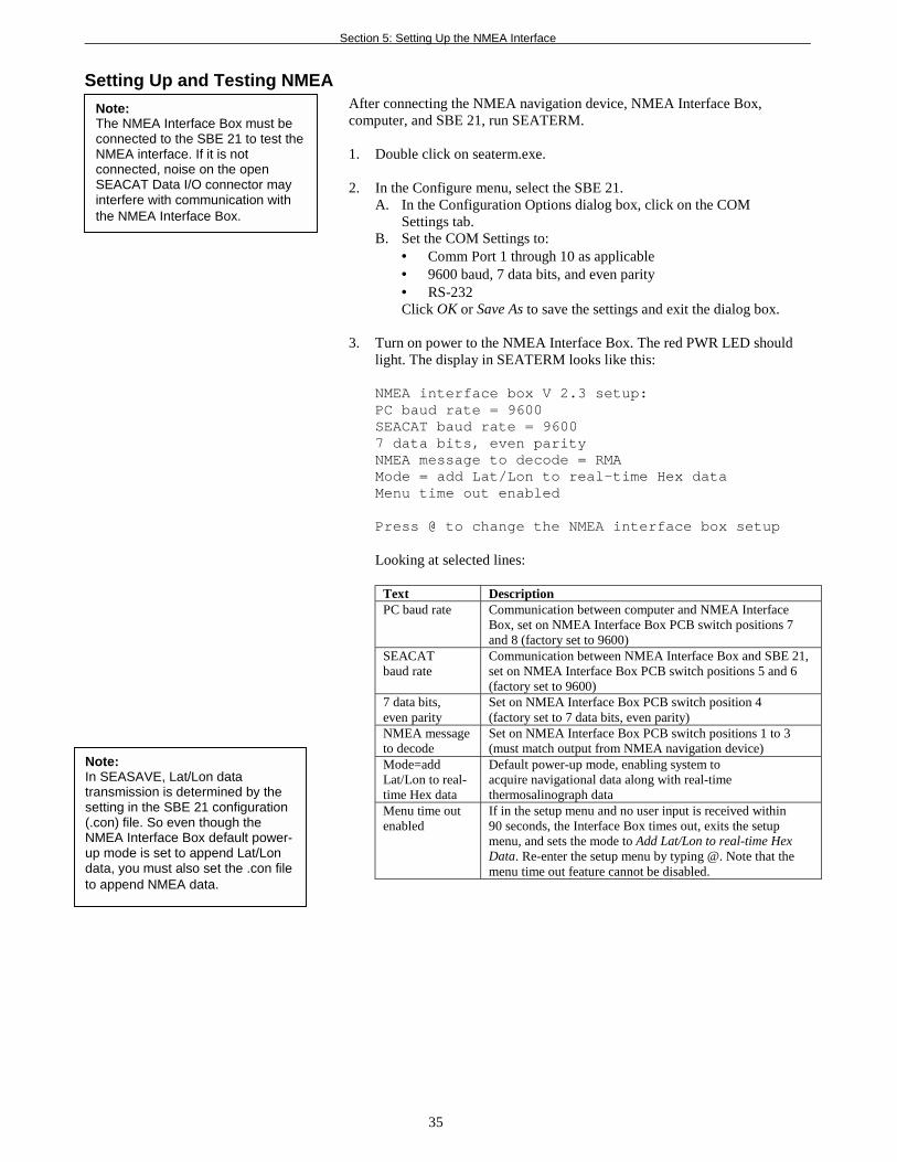
Setting Up and Testing NMEAAfter connecting the NMEA navigation device, NMEA Interface Box,computer, and SBE 21, run SEATERM.
1. Double click on seaterm.exe.
2. In the Configure menu, select the SBE 21.A. In the Configuration Options dialog box, click on the COM
Settings tab.B. Set the COM Settings to:
• Comm Port 1 through 10 as applicable• 9600 baud, 7 data bits, and even parity• RS-232Click OK or Save As to save the settings and exit the dialog box.
3. Turn on power to the NMEA Interface Box. The red PWR LED shouldlight. The display in SEATERM looks like this:
NMEA interface box V 2.3 setup:PC baud rate = 9600SEACAT baud rate = 96007 data bits, even parityNMEA message to decode = RMAMode = add Lat/Lon to real-time Hex dataMenu time out enabled
Press @ to change the NMEA interface box setup
Looking at selected lines:
Text DescriptionPC baud rate Communication between computer and NMEA Interface
Box, set on NMEA Interface Box PCB switch positions 7and 8 (factory set to 9600)
SEACATbaud rate
Communication between NMEA Interface Box and SBE 21,set on NMEA Interface Box PCB switch positions 5 and 6(factory set to 9600)
7 data bits,even parity
Set on NMEA Interface Box PCB switch position 4(factory set to 7 data bits, even parity)
NMEA messageto decode
Set on NMEA Interface Box PCB switch positions 1 to 3(must match output from NMEA navigation device)
Mode=addLat/Lon to real-time Hex data
Default power-up mode, enabling system toacquire navigational data along with real-timethermosalinograph data
Menu time outenabled
If in the setup menu and no user input is received within90 seconds, the Interface Box times out, exits the setupmenu, and sets the mode to Add Lat/Lon to real-time HexData. Re-enter the setup menu by typing @. Note that themenu time out feature cannot be disabled.
Note:The NMEA Interface Box must beconnected to the SBE 21 to test theNMEA interface. If it is notconnected, noise on the openSEACAT Data I/O connector mayinterfere with communication withthe NMEA Interface Box.
Note:In SEASAVE, Lat/Lon datatransmission is determined by thesetting in the SBE 21 configuration(.con) file. So even though theNMEA Interface Box default power-up mode is set to append Lat/Londata, you must also set the .con fileto append NMEA data.
Section 5: Setting Up the NMEA Interface
36
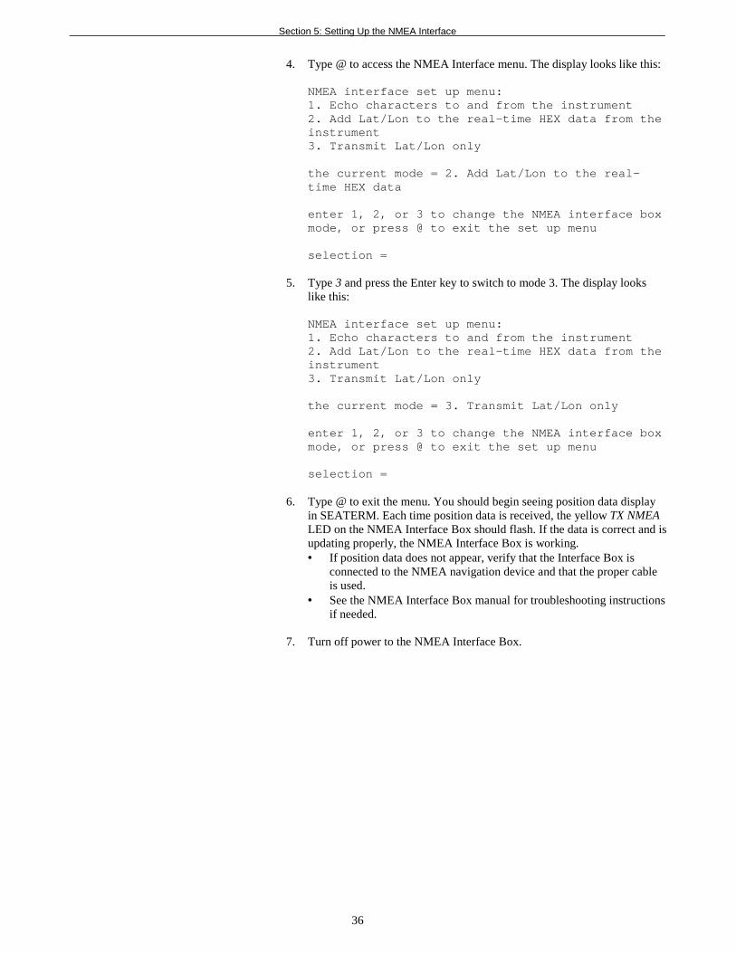
4. Type @ to access the NMEA Interface menu. The display looks like this:
NMEA interface set up menu:1. Echo characters to and from the instrument2. Add Lat/Lon to the real-time HEX data from theinstrument3. Transmit Lat/Lon only
the current mode = 2. Add Lat/Lon to the real-time HEX data
enter 1, 2, or 3 to change the NMEA interface boxmode, or press @ to exit the set up menu
selection =
5. Type 3 and press the Enter key to switch to mode 3. The display lookslike this:
NMEA interface set up menu:1. Echo characters to and from the instrument2. Add Lat/Lon to the real-time HEX data from theinstrument3. Transmit Lat/Lon only
the current mode = 3. Transmit Lat/Lon only
enter 1, 2, or 3 to change the NMEA interface boxmode, or press @ to exit the set up menu
selection =
6. Type @ to exit the menu. You should begin seeing position data displayin SEATERM. Each time position data is received, the yellow TX NMEALED on the NMEA Interface Box should flash. If the data is correct and isupdating properly, the NMEA Interface Box is working.• If position data does not appear, verify that the Interface Box is
connected to the NMEA navigation device and that the proper cableis used.
• See the NMEA Interface Box manual for troubleshooting instructionsif needed.
7. Turn off power to the NMEA Interface Box.
Section 5: Setting Up the NMEA Interface
37
Troubleshooting NMEA Interface
See the NMEA Interface Box manual for troubleshooting.
Setting Up SBE 21 Configuration (.con) File
The NMEA Interface Box integrates the position data from the NMEAnavigation device into the SBE 21 data stream. SEASAVE, Sea-Bird’s real-time data acquisition and display program, stores and optionally displays theNMEA data along with the thermosalinograph data. SEASAVE requires a .confile, which defines the SBE 21 - auxiliary sensors integrated with theinstrument, and channels, serial numbers, and calibration dates andcoefficients for all the integrated sensors (conductivity and temperature as wellas auxiliary sensors). SEASAVE (as well as our data processing software) usesthe information in the .con file to interpret and process the raw data. If the .confile does not match the actual instrument configuration, the software will notbe able to interpret and process the data correctly.
The .con file must indicate if position data is being added to the SBE 21data by the NMEA Interface Box. See Section 4: Setting Up the SBE 21 fordetails on viewing and modifying the .con file in SEASAVE. Note that the.con file setup overrides the mode selection in the NMEA interface setup menu(default power-up mode is to add Lat/Lon to the real-time Hex data from theinstrument). In other words, the real-time transmission of NMEA position datais dependent on the .con file setting in SEASAVE.
Notes:When Sea-Bird ships a newinstrument, we include a .confile that reflects the currentinstrument configuration as weknow it. The .con file is namedwith the instrument serialnumber, followed with the .conextension. For example, for aninstrument with serial number2375, Sea-Bird names the .confile 2375.con. You may renamethe .con file if desired; this willnot affect the results.
Section 6: Operating the System
38
Section 6: Operating the SystemThis section covers:• Acquiring real-time data with SEASAVE• Uploading SBE 21 data from memory
Acquiring Real-Time Data with SEASAVE
Proceed as follows:
1. Turn on power to the NMEA Interface Box.• If AUTORUN=Y (SBE 21 is set up to start logging automatically
when power is turned on), SBE 21 will start logging and willstore data in its internal memory. Note that the data will not appearin SEASAVE until you tell SEASAVE to start real-time dataacquisition below.
• If AUTORUN=N (SBE 21 is not set up to start logging automaticallywhen power is turned on), run SEATERM and send the GL or RLcommand to start logging, then close SEATERM. See Section 4:Setting Up the SBE 21 for details on running SEATERM.
2. Double click on Seasave.exe.
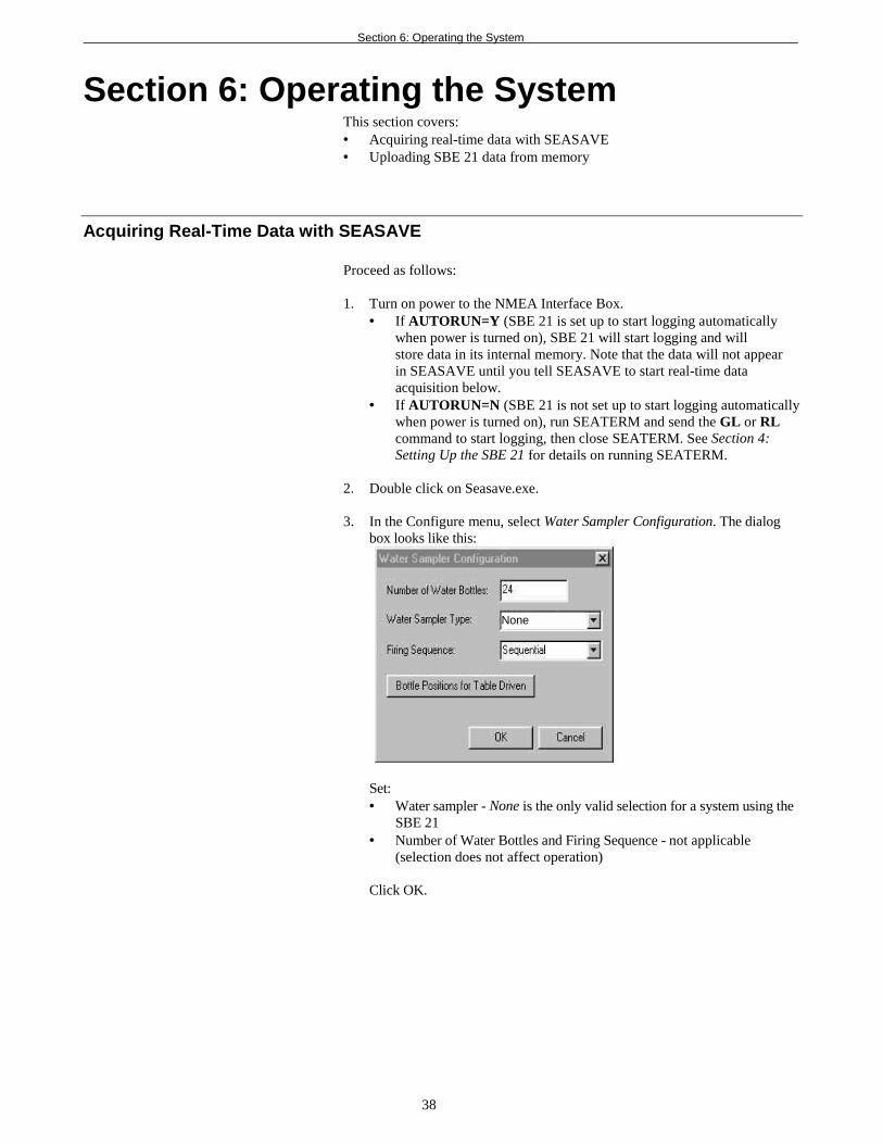
3. In the Configure menu, select Water Sampler Configuration. The dialogbox looks like this:
Set:• Water sampler - None is the only valid selection for a system using the
SBE 21• Number of Water Bottles and Firing Sequence - not applicable
(selection does not affect operation)
Click OK.
None
Section 6: Operating the System
39
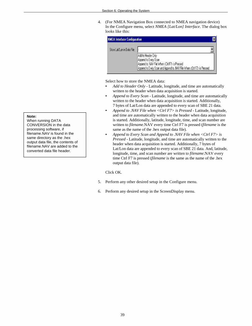
4. (For NMEA Navigation Box connected to NMEA navigation device)In the Configure menu, select NMEA [Lat/Lon] Interface. The dialog boxlooks like this:
Select how to store the NMEA data:• Add to Header Only - Latitude, longitude, and time are automatically
written to the header when data acquisition is started.• Append to Every Scan - Latitude, longitude, and time are automatically
written to the header when data acquisition is started. Additionally,7 bytes of Lat/Lon data are appended to every scan of SBE 21 data.
• Append to .NAV File when <Ctrl F7> is Pressed - Latitude, longitude,and time are automatically written to the header when data acquisitionis started. Additionally, latitude, longitude, time, and scan number arewritten to filename.NAV every time Ctrl F7 is pressed (filename is thesame as the name of the .hex output data file).
• Append to Every Scan and Append to .NAV File when <Ctrl F7> isPressed - Latitude, longitude, and time are automatically written to theheader when data acquisition is started. Additionally, 7 bytes ofLat/Lon data are appended to every scan of SBE 21 data. And, latitude,longitude, time, and scan number are written to filename.NAV everytime Ctrl F7 is pressed (filename is the same as the name of the .hexoutput data file).
Click OK.
5. Perform any other desired setup in the Configure menu.
6. Perform any desired setup in the ScreenDisplay menu.
Note:When running DATACONVERSION in the dataprocessing software, iffilename.NAV is found in thesame directory as the .hexoutput data file, the contents offilename.NAV are added to theconverted data file header.
Section 6: Operating the System
40
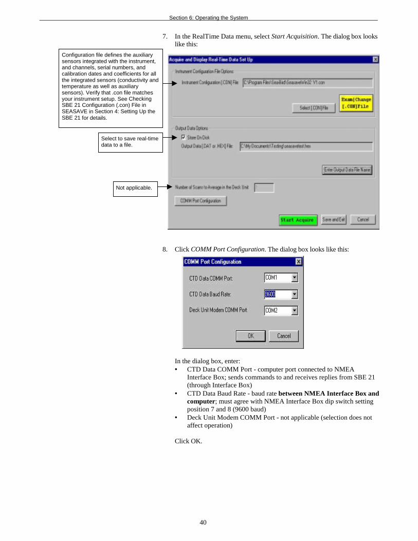
7. In the RealTime Data menu, select Start Acquisition. The dialog box lookslike this:
8. Click COMM Port Configuration. The dialog box looks like this:
In the dialog box, enter:• CTD Data COMM Port - computer port connected to NMEA
Interface Box; sends commands to and receives replies from SBE 21(through Interface Box)
• CTD Data Baud Rate - baud rate between NMEA Interface Box andcomputer; must agree with NMEA Interface Box dip switch settingposition 7 and 8 (9600 baud)
• Deck Unit Modem COMM Port - not applicable (selection does notaffect operation)
Click OK.
Configuration file defines the auxiliarysensors integrated with the instrument,and channels, serial numbers, andcalibration dates and coefficients for allthe integrated sensors (conductivity andtemperature as well as auxiliarysensors). Verify that .con file matchesyour instrument setup. See CheckingSBE 21 Configuration (.con) File inSEASAVE in Section 4: Setting Up theSBE 21 for details.
Select to save real-timedata to a file.
Not applicable.
Section 6: Operating the System
41
9. In the Acquire and Display Real Time Data Set Up dialog box, clickStart Acquire.A. If SEASAVE was set up to prompt for header information (Configure
menu / Header Form), the Header Information dialog box appears.Fill in the desired information to be added to the header portion of thereal-time data acquisition .hex file, and click OK.
B. SEASAVE automatically sends a command to put the NMEAInterface in Mode 1 (do not transmit NMEA data) or Mode 2 (appendposition data to SBE 21 data), depending on whether the SBE 21 .confile was set to add NMEA data. If the .con file was set to add NMEAdata, the screen then displays: Getting Latitude, Longitude and Timefrom the NMEA Interface.
C. Real-time data then starts appearing in the screen display(s).
10. When done acquiring data, in the RealTime Data menu, selectStop Acquisition.
11. Close SEASAVE.
12. Double click on seaterm.exe.A. Establish communications with the SBE 21 by pressing the Enter key
several times. The SBE 21 should respond with an S> prompt.B. Send the QL command to stop logging.C. If you want to upload data from the SBE 21’s memory now, see
Uploading Data from Memory below.D. Send the QS command to place the SBE 21 in quiescent (sleep) state.
13. Turn off power to the NMEA Interface Box.
Note:See the SBE Data Processingmanual and/or help files fordetails on processing the data.
Section 6: Operating the System
42
Uploading SBE 21 Data from Memory
1. Double click on SeaTerm.exe. The display shows the main screen.
2. In the Configure menu, select SBE 21. Click on the Upload Settings tab.The dialog box looks like this:
Make the selection for Upload Settings.
3. Click on the Header Information tab. The dialog box looks like this:
Select the desired header information option. Click OK to overwrite anexisting configuration file, or click Save As to save the configuration as anew filename.
Note:Set up Upload Settings, HeaderInformation, and/or Header Form(Steps 2 through 4):• The first time you upload data, and• If you want to change upload or
header parameters.
Baud rate for uploadingdata from SBE 21 tocomputer; same as baudrate on COM Settings tab.
Defines data upload type when using Upload buttonon Toolbar or Upload Data in Data menu:• All as single file – All data uploaded into one file.• By scan number range – SEATERM prompts for
beginning and ending scan (sample) numbers,and uploads all data within range into one file.
SBE 21 Configuration Options X
Defines headerinformation included withuploaded data:• Prompt for header
information – Eachtime data is uploaded,user is prompted to fillout user-definedheader form.
• Include default headerform in upload file –User-defined defaultheader form included inupload file. User is notprompted to add anyinformation when datais uploaded.
• Don’t include defaultheader form in uploadfile – Headerinformation notincluded in upload file.
SBE 21 Configuration Options X
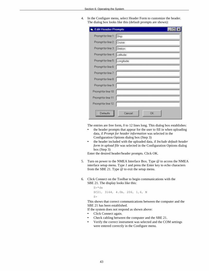
Section 6: Operating the System
43
4. In the Configure menu, select Header Form to customize the header.The dialog box looks like this (default prompts are shown):
The entries are free form, 0 to 12 lines long. This dialog box establishes:• the header prompts that appear for the user to fill in when uploading
data, if Prompt for header information was selected in theConfiguration Options dialog box (Step 3)
• the header included with the uploaded data, if Include default headerform in upload file was selected in the Configuration Options dialogbox (Step 3)
Enter the desired header/header prompts. Click OK.
5. Turn on power to the NMEA Interface Box. Type @ to access the NMEAinterface setup menu. Type 1 and press the Enter key to echo charactersfrom the SBE 21. Type @ to exit the setup menu.
6. Click Connect on the Toolbar to begin communications with theSBE 21. The display looks like this:
S>*ds
SC21, 3164, 4.0b, 206, 1,6, N
S>
This shows that correct communications between the computer and theSBE 21 has been established.If the system does not respond as shown above:• Click Connect again.• Check cabling between the computer and the SBE 21.• Verify the correct instrument was selected and the COM settings
were entered correctly in the Configure menu.
Section 6: Operating the System
44
7. Display SBE 21 status information by clicking Status on the Toolbar. Thedisplay looks like this:SEACAT THERMOSALINOGRAPH V4.0b SERIAL NO. 3166 01/15/2002 14:02:13ioper = 50.7 ma vmain = 11.4, vlith = 8.8samples = 50000, free = 1346736sample interval = 5 secondssample external SBE 38 temperature sensorno. of volts samples = 0output format = SBE21start sampling when power on = nologging data = novoltage cutoff = 7.5 volts
8. If the status reply indicates that the SBE 21 is still logging, command theSBE 21 to stop data logging by pressing the Enter key and sending theQL command. You may need to send the command several times.
9. If output format = SBE16 in the status display, and you intend to useSea-Bird data processing software, send the F1 command to change theoutput format to SBE 21. Verify output format = SBE21 by sending theDS command again.
10. Click the Upload button on the Toolbar to upload stored data in a formthat Sea-Bird’s data processing software can use. SEATERM respondsas follows:A. SEATERM sends the status (DS) command, displays the response,
and writes the command and response to the upload file. Thiscommand provides with information regarding the number of samplesin memory, scan interval, etc.
B. SEATERM sends the header (DH) command, displays the response,and writes the command and response to the upload file. Thiscommand provides information regarding the number of samples ineach cast (SBE 21 writes a header each time sampling is restarted, aswell as every 1000 scans), the date and time the cast was started, andthe sample interval.
C. If you selected By scan number range in the ConfigurationOptions dialog box (Configure menu) – a dialog box requests therange. Enter the desired value(s), and click OK.
D. If you selected Prompt for header information in theConfiguration Options dialog box (Configure menu) – a dialogbox with the header form appears. Enter the desired headerinformation, and click OK.
E. In the Open dialog box, enter the desired upload file name and clickOK. The upload file has a .hex extension.
F. SEATERM sends the data upload command (DDb,e).G. When the data has been uploaded, SEATERM shows the S> prompt.
11. Ensure all data has been uploaded from the SBE 21 by reviewing andprocessing the data:
A. Use SEASAVE (Win 95/98/NT) to display the raw hexadecimal datafrom the SBE 21 in engineering units (see SEASAVE’s manualand/or Help files for details on displaying archived data).
B. Use SBE Data Processing (Win 95/98/NT) to process and plot thedata (see SBE Data Processing’s manual and/or Help files for details).
Notes:To prepare the SBE 21for re-deployment:1. After all data has been uploaded,
send the IL command. If thiscommand is not sent and loggingis started with the RL commandor by applying power, new datawill be stored after the lastrecorded sample, preventing useof the entire memory capacity.
1. Send the QS command to put theSBE 21 in quiescent (sleep) stateuntil ready to restart logging.
1. Turn off power to the NMEAInterface Box.

Section 7: Routine Maintenance and Calibration
45
Section 7: Routine Maintenanceand Calibration
This section reviews corrosion precautions, conductivity cell cleaning andstorage, sensor calibration, and replacement of anti-foul cylinders. Theaccuracy of the SBE 21 is sustained by the care and calibration of the sensorsand by establishing proper handling practices.
Corrosion PrecautionsAll hardware exposed to seawater is titanium; the housing is plastic. Nocorrosion precautions are required. The SBE 21 should be cleaned as describedbelow after use and prior to storage.
Removing Sensor/Electronics Module from SBE 21 Water Jacket
1. Close all 4 valves (valve is closed when the handle is vertical).
2. Remove sensor/electronics module from water jacket:A. Remove the 4 bolts, washers, and nuts securing the square end cap to
the SBE 21 top plate.B. Lift the square end cap straight up, removing the sensor/electronics
module from the water jacket.C. Protect the o-ring on the top plate from damage or contamination.
3. When desired, replace the sensor/electronics module in the water jacket:A. Inspect the top plate o-ring and mating surfaces for dirt, nicks, and
cuts. Clean or replace as necessary. Apply a light coat of o-ringlubricant (Parker Super O Lube) to o-ring and mating surfaces.
B. Carefully replace the sensor/electronics module in the water jacket,aligning the bolt holes on the square end cap and top plate.
C. Reinstall the 4 bolts, washers, and nuts to secure the end cap to thetop plate.
Remove 4 boltssecuring square endcap to top plate
Place all 4 valves invertical (closed) position
Sensor/Electronics Module(anti-foul cylinders not shown)
Connector used only for factory calibrationand testing
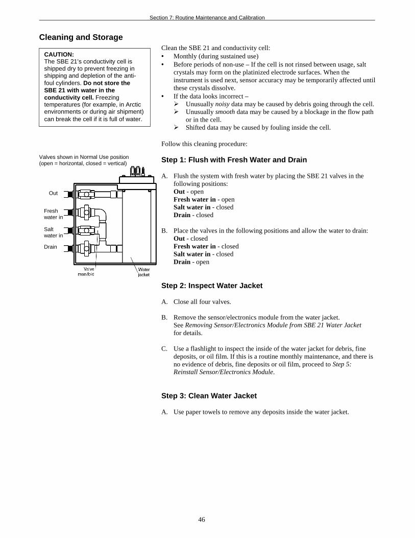
Section 7: Routine Maintenance and Calibration
46
Cleaning and StorageClean the SBE 21 and conductivity cell:• Monthly (during sustained use)• Before periods of non-use – If the cell is not rinsed between usage, salt
crystals may form on the platinized electrode surfaces. When theinstrument is used next, sensor accuracy may be temporarily affected untilthese crystals dissolve.
• If the data looks incorrect –! Unusually noisy data may be caused by debris going through the cell.! Unusually smooth data may be caused by a blockage in the flow path
or in the cell.! Shifted data may be caused by fouling inside the cell.
Follow this cleaning procedure:
Step 1: Flush with Fresh Water and Drain
A. Flush the system with fresh water by placing the SBE 21 valves in thefollowing positions:Out - openFresh water in - openSalt water in - closedDrain - closed
B. Place the valves in the following positions and allow the water to drain:Out - closedFresh water in - closedSalt water in - closedDrain - open
Step 2: Inspect Water Jacket
A. Close all four valves.
B. Remove the sensor/electronics module from the water jacket.See Removing Sensor/Electronics Module from SBE 21 Water Jacketfor details.
C. Use a flashlight to inspect the inside of the water jacket for debris, finedeposits, or oil film. If this is a routine monthly maintenance, and there isno evidence of debris, fine deposits or oil film, proceed to Step 5:Reinstall Sensor/Electronics Module.
Step 3: Clean Water Jacket
A. Use paper towels to remove any deposits inside the water jacket.
CAUTION:The SBE 21’s conductivity cell isshipped dry to prevent freezing inshipping and depletion of the anti-foul cylinders. Do not store theSBE 21 with water in theconductivity cell. Freezingtemperatures (for example, in Arcticenvironments or during air shipment)can break the cell if it is full of water.
Valves shown in Normal Use position(open = horizontal, closed = vertical)
Out
Freshwater in
Saltwater in
Drain
Section 7: Routine Maintenance and Calibration
47
Step 4: Flush Inside of Conductivity Cell
A. Remove the Tygon tubing/anti-foul cylinder from each end of theconductivity cell (see Replacing Anti-Foul Cylinders below for details).
B. Clean the inside of the conductivity cell with a series of flushes, usingTygon tubing.i. Fresh water to remove debris and deposits.ii. 1 liter of 1-normal hydrochloric acid, slow flow through the cell
(Produce 1-normal hydrochloric acid as follows: Start with muriaticacid, which is 31.45% HCl (20 degrees Baume) by weight. Dilute0.1 liters of muriatic acid into 0.9 liters of fresh water.)
iii. 10 liters of fresh water to rinse the acid.iv. (optional) 1 liter of 1% solution of Triton X-100 (Triton X-100 is
included with shipment).If fouling remains in the conductivity cell after these procedures, returnthe sensor/electronics module to Sea-Bird for cleaning and recalibration.
C. Rinse the exterior of the instrument to remove any spilled acid fromthe surface.
D. If the SBE 21 is being stored, remove larger droplets of water by blowingthrough the conductivity cell. Do not use compressed air, whichtypically contains oil vapor.
Step 5: Reinstall Sensor/Electronics Module
A. See Removing Sensor/Electronics Module from SBE 21 Water Jacketfor details on reinstalling the module.
B. If you will not be immediately using the SBE 21, leave all the valves inthe closed position.For Normal use, place the valves in these positions:Out - openFresh water in - closedSalt water in - openDrain - closed
If the data still looks incorrect after cleaning, it may be caused by:• a problem with the electrical connections• a problem with the PCBs inside the sensor/electronics module housing• internal fouling in the conductivity cell that was not removed by flushing• sensors that need to be recalibrated
WARNING!• Wear gloves if touching or
handling the Tygon tubing/anti-foul cylinders.
• Use protective eyewear andwear gloves when working withhydrochloric acid. Avoidbreathing the acid fumes. Diluteand rinse any spills with freshwater, or neutralize large spillswith baking soda (sodiumbicarbonate powder).
CAUTION:Do not put a brush or any objectinside the conductivity cell toclean it or dry it. Touching andbending the electrodes can changethe calibration. Large bends andmovement of the electrodes candamage the cell.
CAUTION:To remove the electronics from thehousing for troubleshooting, seeAppendix II: ElectronicsDisassembly/Reassembly for details.
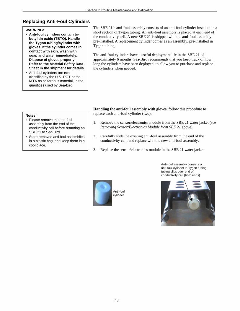
Section 7: Routine Maintenance and Calibration
48
Replacing Anti-Foul CylindersThe SBE 21’s anti-foul assembly consists of an anti-foul cylinder installed in ashort section of Tygon tubing. An anti-foul assembly is placed at each end ofthe conductivity cell. A new SBE 21 is shipped with the anti-foul assemblypre-installed. A replacement cylinder comes as an assembly, pre-installed inTygon tubing.
The anti-foul cylinders have a useful deployment life in the SBE 21 ofapproximately 6 months. Sea-Bird recommends that you keep track of howlong the cylinders have been deployed, to allow you to purchase and replacethe cylinders when needed.
Handling the anti-foul assembly with gloves, follow this procedure toreplace each anti-foul cylinder (two):
1. Remove the sensor/electronics module from the SBE 21 water jacket (seeRemoving Sensor/Electronics Module from SBE 21 above).
2. Carefully slide the existing anti-foul assembly from the end of theconductivity cell, and replace with the new anti-foul assembly.
3. Replace the sensor/electronics module in the SBE 21 water jacket.
WARNING!• Anti-foul cylinders contain tri-
butyl tin oxide (TBTO). Handlethe Tygon tubing/cylinder withgloves. If the cylinder comes incontact with skin, wash withsoap and water immediately.Dispose of gloves properly.Refer to the Material Safety DataSheet in the shipment for details.
• Anti-foul cylinders are notclassified by the U.S. DOT or theIATA as hazardous material, in thequantities used by Sea-Bird.
Anti-foul assembly consists ofanti-foul cylinder in Tygon tubing;tubing slips over end ofconductivity cell (both ends)
Anti-foulcylinder
Notes:• Please remove the anti-foul
assembly from the end of theconductivity cell before returning anSBE 21 to Sea-Bird.
• Store removed anti-foul assembliesin a plastic bag, and keep them in acool place.
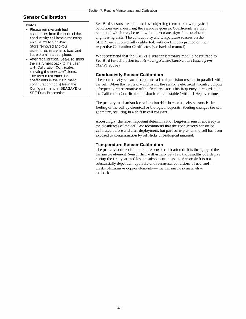
Section 7: Routine Maintenance and Calibration
49
Sensor CalibrationSea-Bird sensors are calibrated by subjecting them to known physicalconditions and measuring the sensor responses. Coefficients are thencomputed which may be used with appropriate algorithms to obtainengineering units. The conductivity and temperature sensors on theSBE 21 are supplied fully calibrated, with coefficients printed on theirrespective Calibration Certificates (see back of manual).
We recommend that the SBE 21’s sensor/electronics module be returned toSea-Bird for calibration (see Removing Sensor/Electronics Module fromSBE 21 above).
Conductivity Sensor CalibrationThe conductivity sensor incorporates a fixed precision resistor in parallel withthe cell. When the cell is dry and in air, the sensor’s electrical circuitry outputsa frequency representative of the fixed resistor. This frequency is recorded onthe Calibration Certificate and should remain stable (within 1 Hz) over time.
The primary mechanism for calibration drift in conductivity sensors is thefouling of the cell by chemical or biological deposits. Fouling changes the cellgeometry, resulting in a shift in cell constant.
Accordingly, the most important determinant of long-term sensor accuracy isthe cleanliness of the cell. We recommend that the conductivity sensor becalibrated before and after deployment, but particularly when the cell has beenexposed to contamination by oil slicks or biological material.
Temperature Sensor CalibrationThe primary source of temperature sensor calibration drift is the aging of thethermistor element. Sensor drift will usually be a few thousandths of a degreeduring the first year, and less in subsequent intervals. Sensor drift is notsubstantially dependent upon the environmental conditions of use, and —unlike platinum or copper elements — the thermistor is insensitiveto shock.
Notes:• Please remove anti-foul
assemblies from the ends of theconductivity cell before returningan SBE 21 to Sea-Bird.Store removed anti-foulassemblies in a plastic bag, andkeep them in a cool place.
• After recalibration, Sea-Bird shipsthe instrument back to the userwith Calibration Certificatesshowing the new coefficients.The user must enter thecoefficients in the instrumentconfiguration (.con) file in theConfigure menu in SEASAVE orSBE Data Processing.
Section 8: Troubleshooting
50
Section 8: TroubleshootingThis section reviews common problems in operating the SBE 21, and providesthe most common causes and solutions.
Each SBE 21 is shipped with a configuration (.con) file that matches theconfiguration of the instrument (number and type of auxiliary sensors, etc.)and includes the instrument calibration coefficients.
Problem 1: Unable to Communicate with NMEA Interface Box
The NMEA Interface Box setup message indicates that communicationsbetween the NMEA Interface Box and computer have been established. Beforeproceeding with troubleshooting, attempt to establish communications againby typing @ several times.
Cause/Solution 1: The I/O cable connection may be loose. Check the cablingbetween the NMEA Interface Box and computer for a loose connection.
Problem 2: Unable to Communicate with SBE 21
The S> prompt indicates that communications between the SBE 21 andcomputer have been established. Before proceeding with troubleshooting,attempt to establish communications again by clicking the Connect button onSEATERM’s toolbar or hitting the Enter key several times.
Cause/Solution 1: The I/O cable connection may be loose. Check the cablingbetween the SBE 21 and NMEA Interface Box for a loose connection.
Cause/Solution 2: The instrument type and/or its communication settings maynot have been entered correctly in SEATERM. Select the SBE 21 in theConfigure menu and verify the settings in the Configuration Options dialogbox. The settings should match those on the instrument Configuration Sheet.
Cause/Solution 3: The communication settings entered in SEATERM maynot match the dip switch settings in the NMEA Interface Box. Select theSBE 21 in the Configure menu and verify the settings in the ConfigurationOptions dialog box. If necessary, change the communication settings or the dipswitch settings.
Cause/Solution 3: The I/O cable connecting the SBE 21 to the NMEAInterface Box may not be the correct one. Verify the cable is the correct one.
Problem 3: No Data Recorded
Cause/Solution 1: The SBE 21’s memory may be full; once the memory isfull, no further data will be recorded. Verify that the memory is not full usingthe DS command (free = 0 or 1 if memory is full). Sea-Bird recommends thatyou upload all previous data before beginning another deployment. Once thedata is uploaded, use the IL command to reset the memory. After the memoryis reset, the DS command will show samples = 0.
Section 8: Troubleshooting
51
Problem 4: Nonsense or Unreasonable Data
The symptom of this problem is an uploaded file that contains nonsense values(for example, 9999.999) or unreasonable values (for example, values that areoutside the expected range of the data).
Cause/Solution 1: An uploaded data file with nonsense values may be causedby incorrect instrument configuration in the .con file. Verify the settings in theinstrument .con file match the instrument Configuration Sheet.
Cause/Solution 2: An uploaded data file with unreasonable (i.e., out of theexpected range) values for temperature, conductivity, etc. may be caused byincorrect calibration coefficients in the instrument .con file. Verify thecalibration coefficients in the instrument .con file match the instrumentCalibration Certificates.
Problem 5: Salinity Lower than Expected
Cause/Solution 1: A fouled conductivity cell will report lower than correctsalinity. Large errors in salinity indicate that the cell is extremely dirty, hassomething large lodged in it, or is broken. Proceed as follows:1. Clean the conductivity cell as described in Cleaning and Storage in
Section 7: Routine Maintenance and Calibration.2. Remove larger droplets of water by blowing through the conductivity cell.
Do not use compressed air, which typically contains oil vapor.3. Running the SBE 21 in air, collect some data in SEASAVE and look at
the raw conductivity frequency. It should be within 1 Hz of the zeroconductivity value printed on the conductivity cell Calibration Sheet. If itis significantly different, the cell is probably damaged.
Problem 6: Program Corrupted
Cause/Solution 1: In rare cases, a severe static shock or other problem cancorrupt the program that controls the SBE 21’s microprocessor. This programcan be reset by removing the J1 jumper on the Power PCB. Proceed as followsto initialize:1. Remove the sensor/electronics module from the water jacket, and remove
the electronics from the housing (see Appendix II: ElectronicsDisassembly/Reassembly for details).
2. Remove the J1 jumper from the Power PCB (top board in the PCBassembly). This jumper is used to disconnect the back-up lithium batteryfrom the electronics. Leave the jumper off for several minutes.
3. Reinstall the J1 jumper.4. Reinstall the electronics in the housing, and replace the sensor/electronics
module in the water jacket.5. Establish communications with the SBE 21 (see Section 4: Setting Up the
SBE 21 for details). Initialize logging with the IL command, and set thedate and time with the ST command. Use the DS command to verify thatthe date and time and sample number are correct.
Note:Performing a reset affects theSBE 21’s memory.• Download all data in memory
before performing the reset.• After performing the reset, set the
date and time (ST) and initializelogging (IL). Other setupparameters are unaffected.
Glossary
52
GlossaryAnti-foul cylinder – Expendable device saturated with a tri-butyl-tin basedtoxin placed inside Tygon tubing, located at each end of the conductivity cell.
Fouling – Biological growth in the conductivity cell during deployment.
PCB – Printed Circuit Board.
SBE Data Processing – Sea-Bird’s WIN 95/98/NT data processingsoftware, which calculates temperature and conductivity, as well as data fromauxiliary sensors, and derives variables such as salinity and sound velocity.
Scan – One data sample containing temperature and conductivity, as well asdata from auxiliary sensors.
SEACAT – High-accuracy conductivity, temperature, and pressure recorder.The SEACAT is available as the SBE 16plus (moored applications),SBE 19plus (profiling or moored applications), and SBE 21(thermosalinograph, no pressure).
SEASAVE – Sea-Bird’s WIN 95/98/NT software used to acquire, convert,and display real-time or archived raw data.
SEASOFT-DOS – Sea-Bird’s complete DOS software package, whichincludes software for communication, real-time data acquisition, and dataanalysis and display. SEASOFT-DOS also includes NMEA navigationdevice simulation programs that you can use when troubleshootingproblems with NMEA data. SEASOFT-DOS modules for real-time dataacquisition and data analysis are not compatible with the data output format ofthe SBE 21.
SEASOFT-Win32– Sea-Bird’s complete Win 95/98/NT software package,which includes software for communication, real-time data acquisition, anddata analysis and display. SEASOFT-Win32 includes SEATERM,SeatermAF, SEASAVE, SBE Data Processing, and PLOT39.
SEATERM – Sea-Bird’s Win 95/98/NT terminal program used tocommunicate with the NMEA Interface Box and SBE 21. SEATERM cansend commands to the SBE 21 to provide status display, data acquisition setup,data display and capture, and diagnostic tests.
TCXO – Temperature Compensated Crystal Oscillator.
Triton X-100 – Concentrated liquid non-ionic detergent, used for cleaningthe conductivity cell.
Appendix I: Functional Description
53
Appendix I: Functional Description
SensorsThe SBE 21 embodies the same sensor elements (3-electrode, 2-terminal,borosilicate glass cell and pressure-protected thermistor) previously employedin Sea-Bird’s modular SBE 3 and SBE 4 sensors and in the original SEACATdesign. The current version of the SBE 21 differs from older versions of theSBE 21 in that it uses two independent channels to digitize temperature andconductivity concurrently. Multiplexing is not used for these channels.
Sensor InterfaceTemperature is acquired by applying an AC excitation to a bridge circuitcontaining an ultra-stable aged thermistor with a drift rate of less than 0.002 ºCper year. The other elements in the bridge are VISHAY precision resistors.A 24-bit A/D converter digitizes the output of the bridge. AC excitation andratiometric comparison avoids errors caused by parasitic thermocouples, offsetvoltages, leakage currents, and reference errors.
Conductivity is acquired using an ultra-precision Wein-Bridge oscillator togenerate a frequency output in response to changes in conductivity.
The four external 0 to 5 volt DC voltage channels are processed by differentialamplifiers with an input resistance of 50K ohms and are digitized with a 12-bitA/D converter.
Real-Time ClockTo minimize power and improve clock accuracy, a temperature-compensatedcrystal oscillator (TCXO) is used as the real-time-clock frequency source.The TCXO is accurate to ± 1 minute per year (0 ºC to 40 ºC).
PowerThe Power PCB contains three series-connected lithium cells (1/2 AA non-hazardous) which are diode OR’d with the external power source. The lithiumsupply is capable of supporting all SBE 21 functions and serves to permitorderly shutdown in the event of failure or removal of external power.External power can be removed without disturbing memory or thereal-time clock.

Appendix II: Electronics Disassembly/Reassembly
54
Appendix II: ElectronicsDisassembly/Reassembly
Do not disassemble the SBE 21 electronics unless you are troubleshooting aproblem, and need to access the PCBs.
Sea-Bird provides a jackscrew kit with the SBE 21, to assist in removal of theelectronics end cap. The kit contains:• 2 Allen wrenches• 3 jackscrews
Disassembly
1. As a precaution, upload any data in memory before beginning.See Uploading Data from Memory in Section 6: Operating the Systemfor details.
2. Remove the SBE 21 sensor/electronics module from the water jacket, asdescribed in Removing Sensor/Electronics Module from SBE 21 WaterJacket in Section 7: Routine Maintenance and Calibration.
3. Remove the 2 slotted head screws securing the sensor guard to thehousing. Do not remove the 2 screws holding the conductivity cellguard to the sensor end cap.
4. Remove the sensor end cap (with attached conductivity cell and cellguard) and electronics as follows:
A. Wipe the outside of the sensor end cap and housing dry, being carefulto remove any water at the seam between them.
B. Remove the 4 socket head screws securing the end cap to the housing.C. Remove the 3 plastic hex head screws from the end cap using the
larger Allen wrench. Insert the three jackscrews in these three holesin the end cap. When you begin to feel resistance, use the smallerAllen wrench to continue turning the screws. Turn each screw 1/2turn at a time. As you turn the jackscrews, the end cap will push awayfrom the housing.
D. When the end cap is loosened, carefully slide the end cap andattached electronics out of the housing.
E. Remove any water from the o-rings and mating surfaces inside thehousing with a lint-free cloth or tissue.
F. Disconnect the Molex connectors connecting the PCB assembly tothe housing.
G. Be careful to protect the o-rings from damage or contamination.
Note:Do not disassemble the SBE 21electronics to send the sensors orPCBs to Sea-Bird for recalibration orrepair. Package the sensor/electronicsmodule for shipment, after removingthe anti-foul cylinders (see Section 7:Routine Maintenance and Calibration).
Do not remove sockethead screw attachingguard to sensor endcap (2 places)
Remove slottedhead screw(2 places)
Jackscrewkit
Then remove3 plastic screwsand installjackscrews intheir place
Remove 4 sockethead screws
CAUTION:Avoid getting anything on thePCB, which can be damaged bywater or other materials.
Appendix II: Electronics Disassembly/Reassembly
55
Reassembly1. Remove any water from the O-rings and mating surfaces with a lint-free
cloth or tissue. Inspect the O-rings and mating surfaces for dirt, nicks, andcuts. Clean as necessary. Apply a light coat of O-ring lubricant (ParkerSuper O Lube) to O-rings and mating surfaces.
2. Reconnect the Molex connectors to the PCB assembly.
3. Carefully fit the PCB assembly into the housing, aligning the holes inthe end cap and housing, and the holes in the conductivity cell guardand housing.
4. Reinstall the 4 socket head screws to secure the end cap to the housing.
5. Reinstall the 3 plastic screws in the end cap.
6. Reinstall the 2 slotted screws to secure the conductivity cell guard tothe housing.
Note:Before delivery, a desiccant packageis placed in the housing, and thehousing is filled with dry Argon.These measures help preventcondensation. If the electronics areexposed to the atmosphere formore than an hour, allow thedesiccating process to continueinside the reassembled housingfor one week before performingcalibrations or other critical work.If this is not done, conductivityreadings may be in error by asmuch as 0.001 S/m.
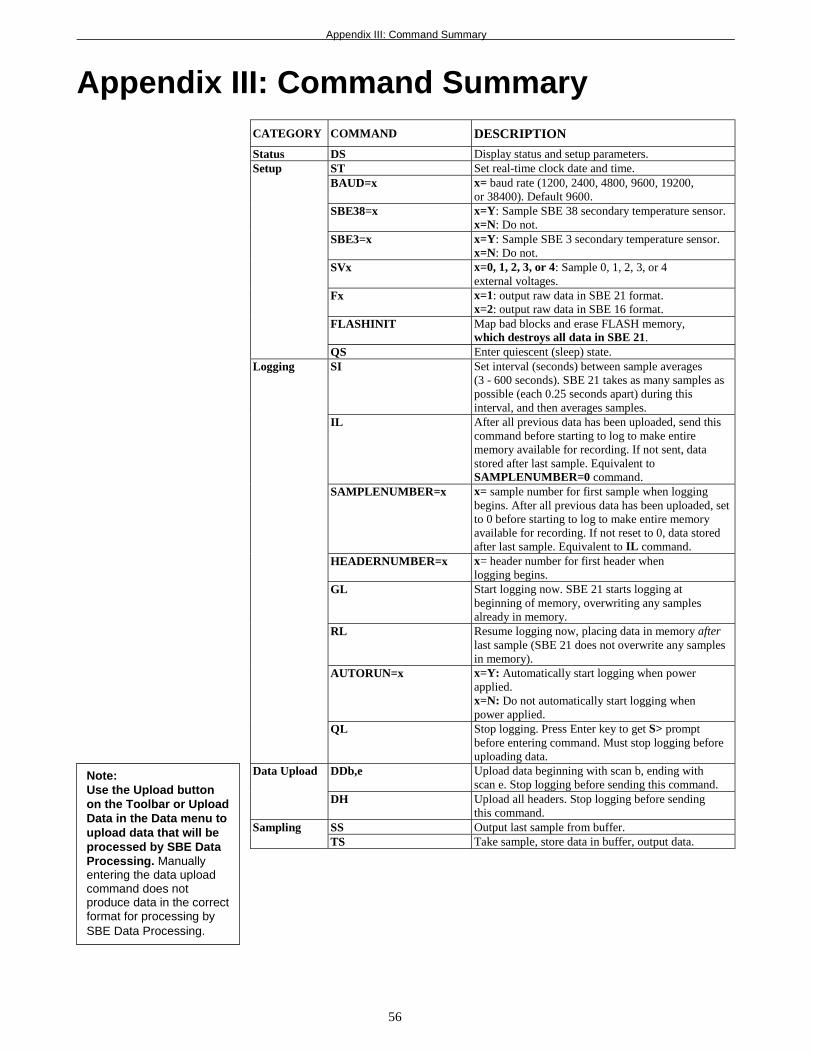
Appendix III: Command Summary
56
Appendix III: Command SummaryCATEGORY COMMAND DESCRIPTION
Status DS Display status and setup parameters.ST Set real-time clock date and time.BAUD=x x= baud rate (1200, 2400, 4800, 9600, 19200,
or 38400). Default 9600.SBE38=x x=Y: Sample SBE 38 secondary temperature sensor.
x=N: Do not.SBE3=x x=Y: Sample SBE 3 secondary temperature sensor.
x=N: Do not.SVx x=0, 1, 2, 3, or 4: Sample 0, 1, 2, 3, or 4
external voltages.Fx x=1: output raw data in SBE 21 format.
x=2: output raw data in SBE 16 format.FLASHINIT Map bad blocks and erase FLASH memory,
which destroys all data in SBE 21.
Setup
QS Enter quiescent (sleep) state.SI Set interval (seconds) between sample averages
(3 - 600 seconds). SBE 21 takes as many samples aspossible (each 0.25 seconds apart) during thisinterval, and then averages samples.
IL After all previous data has been uploaded, send thiscommand before starting to log to make entirememory available for recording. If not sent, datastored after last sample. Equivalent toSAMPLENUMBER=0 command.
SAMPLENUMBER=x x= sample number for first sample when loggingbegins. After all previous data has been uploaded, setto 0 before starting to log to make entire memoryavailable for recording. If not reset to 0, data storedafter last sample. Equivalent to IL command.
HEADERNUMBER=x x= header number for first header whenlogging begins.
GL Start logging now. SBE 21 starts logging atbeginning of memory, overwriting any samplesalready in memory.
RL Resume logging now, placing data in memory afterlast sample (SBE 21 does not overwrite any samplesin memory).
AUTORUN=x x=Y: Automatically start logging when powerapplied.x=N: Do not automatically start logging whenpower applied.
Logging
QL Stop logging. Press Enter key to get S> promptbefore entering command. Must stop logging beforeuploading data.
DDb,e Upload data beginning with scan b, ending withscan e. Stop logging before sending this command.
Data Upload
DH Upload all headers. Stop logging before sendingthis command.
SS Output last sample from buffer.SamplingTS Take sample, store data in buffer, output data.
Note:Use the Upload buttonon the Toolbar or UploadData in the Data menu toupload data that will beprocessed by SBE DataProcessing. Manuallyentering the data uploadcommand does notproduce data in the correctformat for processing bySBE Data Processing.
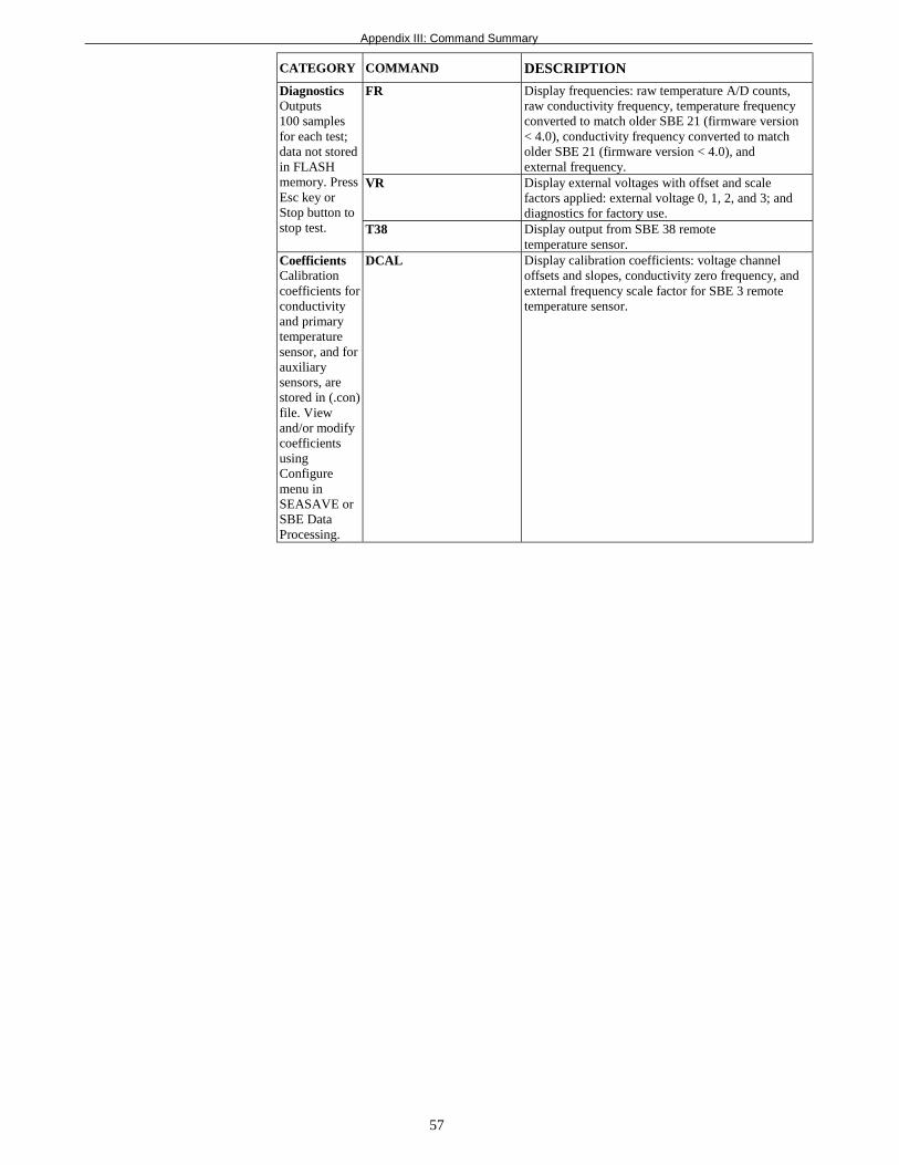
Appendix III: Command Summary
57
CATEGORY COMMAND DESCRIPTION
FR Display frequencies: raw temperature A/D counts,raw conductivity frequency, temperature frequencyconverted to match older SBE 21 (firmware version< 4.0), conductivity frequency converted to matcholder SBE 21 (firmware version < 4.0), andexternal frequency.
VR Display external voltages with offset and scalefactors applied: external voltage 0, 1, 2, and 3; anddiagnostics for factory use.
DiagnosticsOutputs100 samplesfor each test;data not storedin FLASHmemory. PressEsc key orStop button tostop test. T38 Display output from SBE 38 remote
temperature sensor.CoefficientsCalibrationcoefficients forconductivityand primarytemperaturesensor, and forauxiliarysensors, arestored in (.con)file. Viewand/or modifycoefficientsusingConfiguremenu inSEASAVE orSBE DataProcessing.
DCAL Display calibration coefficients: voltage channeloffsets and slopes, conductivity zero frequency, andexternal frequency scale factor for SBE 3 remotetemperature sensor.

Appendix IV: Replacement Parts
58
Appendix IV: Replacement PartsPart
NumberPart Application Description
Quantity inSBE 21
24012 Anti-foul attachments(2)
Anti-foul cylinder in shortsection of Tygon tubing, forplacement at ends ofconductivity cell
2
30200 Bolt, 3/8-16 x 3 3/4Hex, stainless steel
Secures square end cap toSBE 21 top plate
4
30210 Nut, 3/8-16 nylon stop,stainless steel
Use with 30200 4
30257 Washer, 3/8 flat,stainless steel,7/8 OD max
Use with 30200 8
30092 O-ring,Parker 2-363N674-70
O-ring between SBE 21 topplate and square end cap
1
30444 Bolt, 10-24 x 1/2 hexhead, titanium
Attaches conductivity cellguard to sensor/electronicsmodule end cap
2
30491 Machine screw, 8-32 x5/16 slot, titanium
Attaches conductivity cellguard to sensor/electronicsmodule housing
2
30493 Machine screw, 10-24 x1 1/4 hex head, titanium
Attaches sensor/electronicsmodule end cap to housing
4
30815 O-ring,Parker 2-233E603-70
Seal for sensor/electronicsmodule end cap
1
50091 Triton X-100 Conductivity cell cleaningsolution
1
80438 4-pin I/O cable (10 m) From SBE 21 to NMEAInterface Box
1
50298 Spare hardware/O-ring kit for SBE 21compatible with SBE 38remote temperaturesensor
Assorted hardware andO-rings
-
50107 Spare hardware/O-ring kit for SBE 21compatible with SBE 3remote temperaturesensor
Assorted hardware andO-rings
-
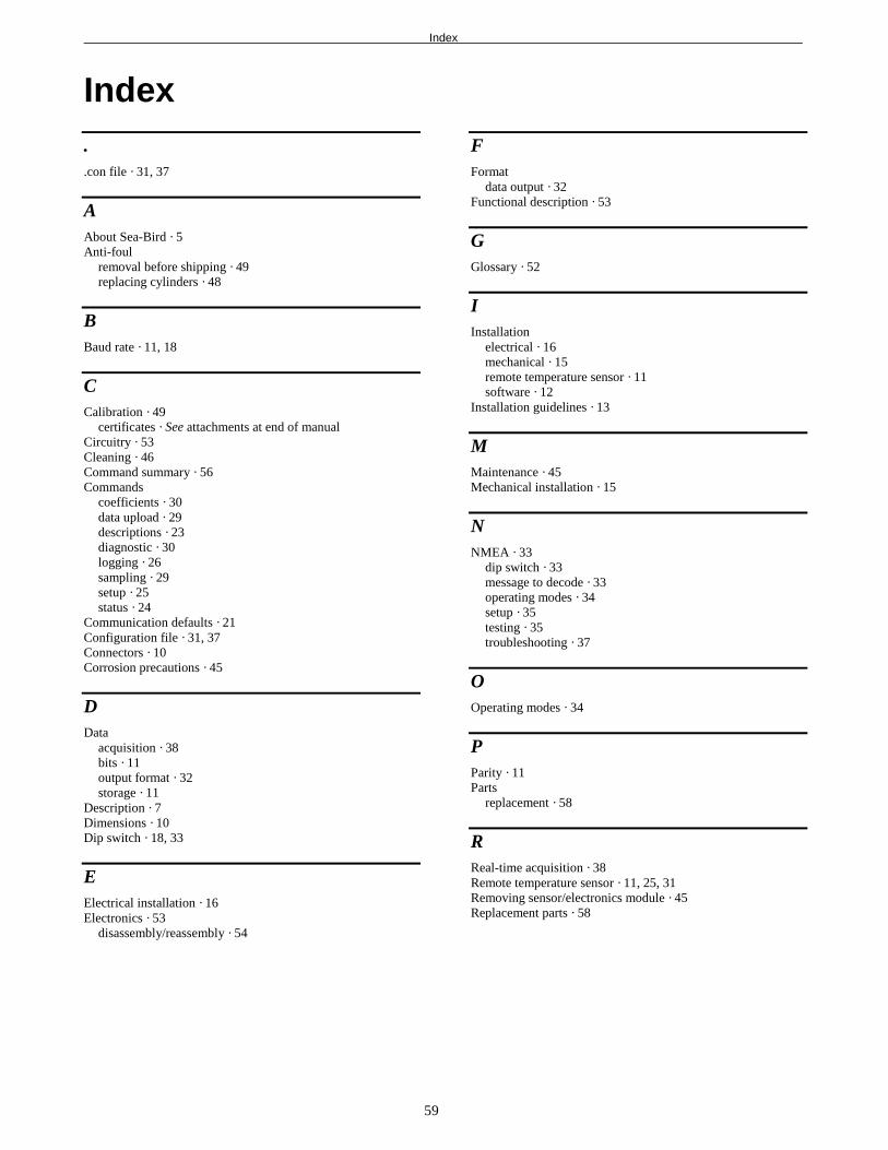
Index
59
Index..con file · 31, 37
AAbout Sea-Bird · 5Anti-foul
removal before shipping · 49replacing cylinders · 48
BBaud rate · 11, 18
CCalibration · 49
certificates · See attachments at end of manualCircuitry · 53Cleaning · 46Command summary · 56Commands
coefficients · 30data upload · 29descriptions · 23diagnostic · 30logging · 26sampling · 29setup · 25status · 24
Communication defaults · 21Configuration file · 31, 37Connectors · 10Corrosion precautions · 45
DData
acquisition · 38bits · 11output format · 32storage · 11
Description · 7Dimensions · 10Dip switch · 18, 33
EElectrical installation · 16Electronics · 53
disassembly/reassembly · 54
FFormat
data output · 32Functional description · 53
GGlossary · 52
IInstallation
electrical · 16mechanical · 15remote temperature sensor · 11software · 12
Installation guidelines · 13
MMaintenance · 45Mechanical installation · 15
NNMEA · 33
dip switch · 33message to decode · 33operating modes · 34setup · 35testing · 35troubleshooting · 37
OOperating modes · 34
PParity · 11Parts
replacement · 58
RReal-time acquisition · 38Remote temperature sensor · 11, 25, 31Removing sensor/electronics module · 45Replacement parts · 58
Index
60
SSBE 38 · 11, 25, 31SBE Data Processing · 8, 12, 44Schematic · 13Schematics · See attachments at end of manualSEASAVE · 8, 12, 38, 44SEASOFT · 8SEASOFT-DOS · 12SEASOFT-Win32 · 12SEATERM · 8, 12, 19, 42
toolbar buttons · 20sensor/electronics module · 45Sensors · 53Service information · See attachment at end of manualSetting up SBE 21 · 18Software · 8, 12Specifications · 9Stop bits · 11Storage · 46System
description · 7schematic · 13
TTesting · 19, 35Troubleshooting · 46, 50
UUnpacking · 6Uploading data · 42
WWarranty · See attachment at end of manual