Embed Size (px)
DESCRIPTION
waukesha bulletin
Citation preview
GE Power & Water
SAFETY ALERT: Failure to comply with this safety alert could result in personal injury or equipment damage. All field sites should be inspected and, if necessary, corrected as soon as feasible.The purpose of this bulletin is to reinform the field andclarify the required inspection and replacementintervals of the rubber flex connectors. Coolant leaksat the rubber flex connectors have been reported onsome APG 2000/3000 Enginators (see Figure 1 andFigure 2). These leaks can be prevented by inspectingand replacing the rubber flex connectors at the properintervals.
Inspect the rubber flex connectors every 3,000 hours.Acceptance should be based on but not limited to thefollowing:
• Any signs of leakage
• Any signs of degradation or splitting of the outerrubber flex connectors
• Any hardening of the rubber flex connectors
• Any signs of separation between the rubber flexconnectors and metal flange
• Any bulging or deformation in the shape of therubber flex connectors
• A running service life of 12,000 hours
• A service life of 5 years independent of running time
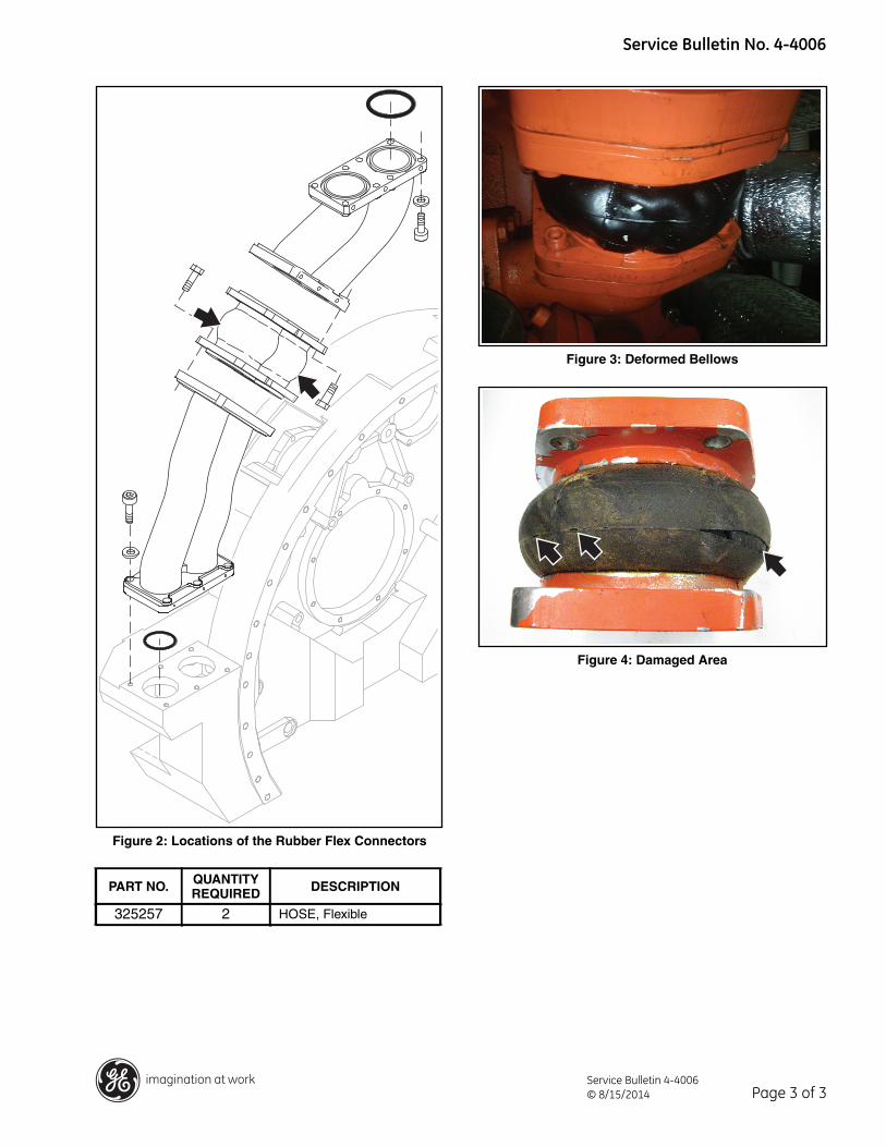
If any of the preceding conditions are present (seeFigure 3 and Figure 4 for examples), replace the flexconnectors at the first opportunity. It is highlyrecommended that all rubber flex connectors arechanged when any one shows degradation.
As is general good practice:
• Make sure that the engine room ventilation systemand all safety systems are working properly.
• Do not enter the engine room of a running engineunless it is necessary.
• Follow all GE Waukesha and site-specific safetyprecautions including using proper personalprotection equipment.
Waukesha* gas engines TOPIC: Cooling SystemSAFETY ALERT
IDENT NO: 4-4006DATE: August 2014
SUPERSEDES: New
SUBJECT: Required Inspection/Replacement of Rubber Flex Connectors
MODELS AFFECTED: All APG 2000/3000 Enginators
APG*APG*
Page 1 of 3Service Bulletin 4-4006© 8/15/2014
* Trademark of General Electric Company
Service Bulletin No. 4-4006
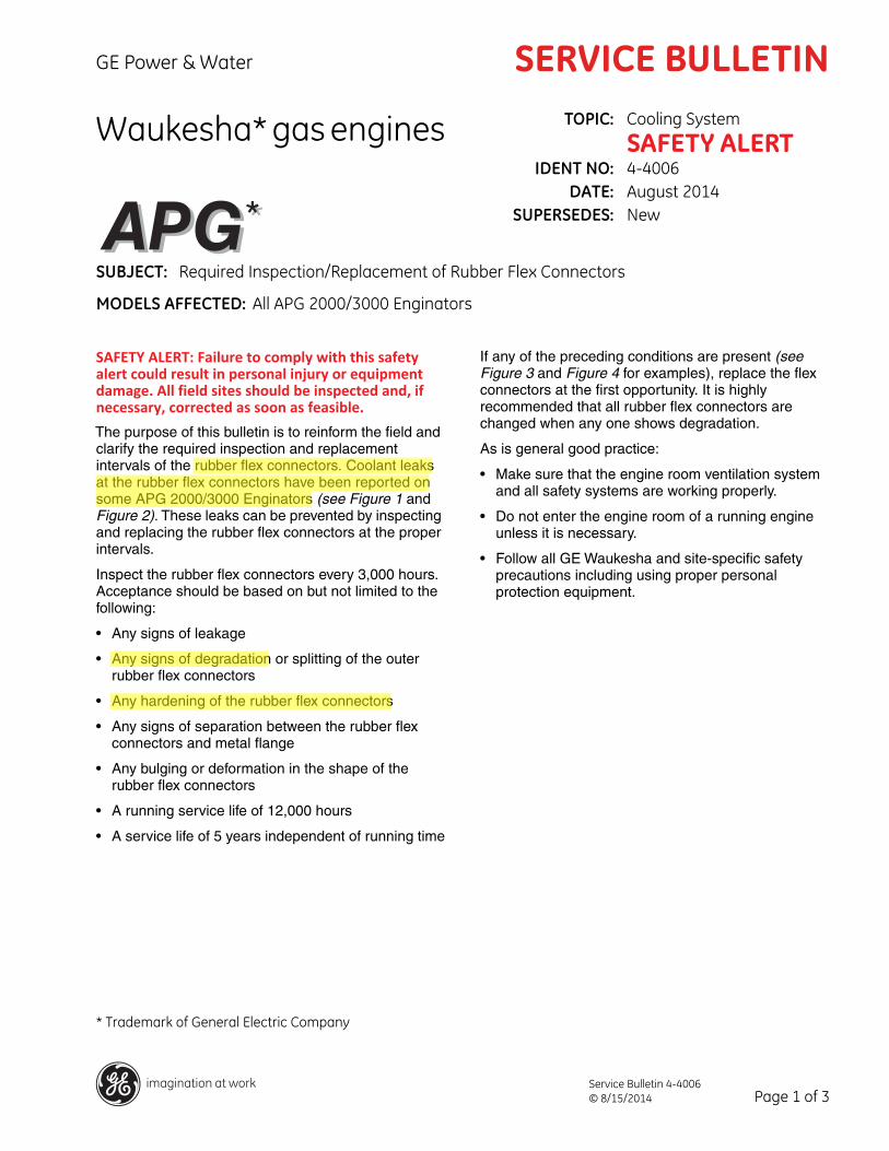
Figure 1: Locations of the Rubber Flex Connectors
PART NO. QUANTITY REQUIRED DESCRIPTION
3341813 6 HOSE, Flexible
Page 2 of 3Service Bulletin 4-4006© 8/15/2014
Service Bulletin No. 4-4006
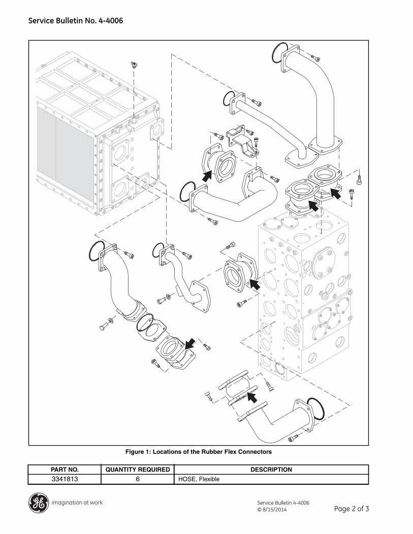
Figure 2: Locations of the Rubber Flex Connectors
Figure 3: Deformed Bellows
Figure 4: Damaged Area
PART NO. QUANTITYREQUIRED DESCRIPTION
325257 2 HOSE, Flexible
Page 3 of 3Service Bulletin 4-4006© 8/15/2014