Embed Size (px)
Citation preview
Satellite Communications
Chapter 9
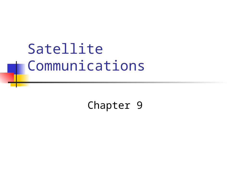
Heart of satellite communication: satellite based antenna in a stable orbit (satellite trajectory) above the earth. Micro-Wave frequencies

Satellite-Related Terms Earth Stations – antenna systems on or near earth Satellites : one or more satellites that serve as relay
stations Uplink – transmission from an earth station to a
satellite Downlink – transmission from a satellite to an earth
station Transponder – electronics in the satellite that convert
uplink signals to downlink signals
Satellite-based vs terrestrial wireless communication
The area of coverage of a satellite system far exceeds that of a terrestrial system. In the case of a geostationary satellite, a single satellite based-
antenna is visible to about one-fourth of the earth's surface. Conditions between communicating satellites are more time
invariant than those between satellite and earth station or between two terrestrial wireless antennas. Thus, satellite-to-satellite communication links can be
designed with great precision. Very high bandwidths or data rates are available to the user. For a geostationary satellite, there is an earth-satellite-earth
propagation delay of about one-fourth of a second.
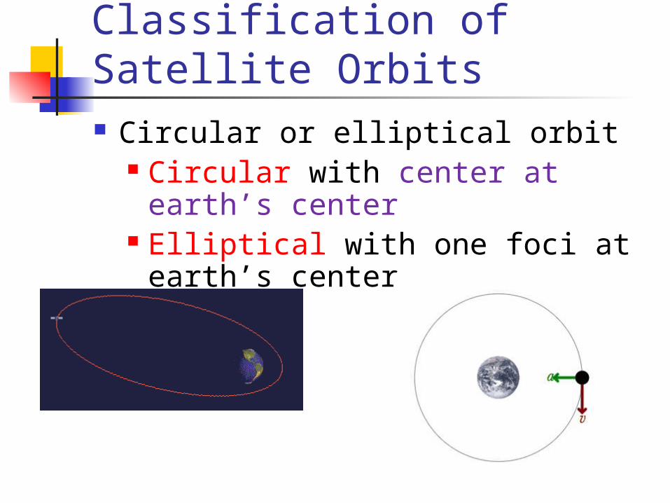
Classification of Satellite Orbits Circular or elliptical orbit
Circular with center at earth’s center Elliptical with one foci at earth’s center
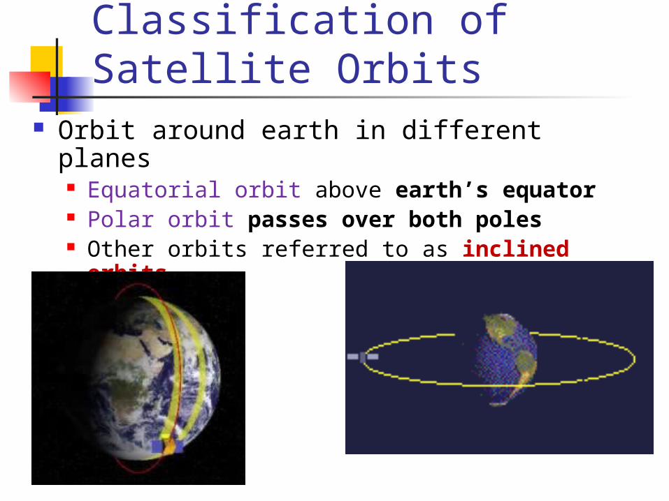
Classification of Satellite Orbits Orbit around earth in different planes
Equatorial orbit above earth’s equator Polar orbit passes over both poles Other orbits referred to as inclined orbits

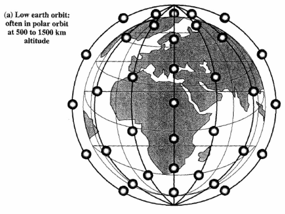
Classification of Satellite Orbits Altitude of satellites
Geostationary orbit (GEO) Medium earth orbit (MEO) Low earth orbit (LEO)
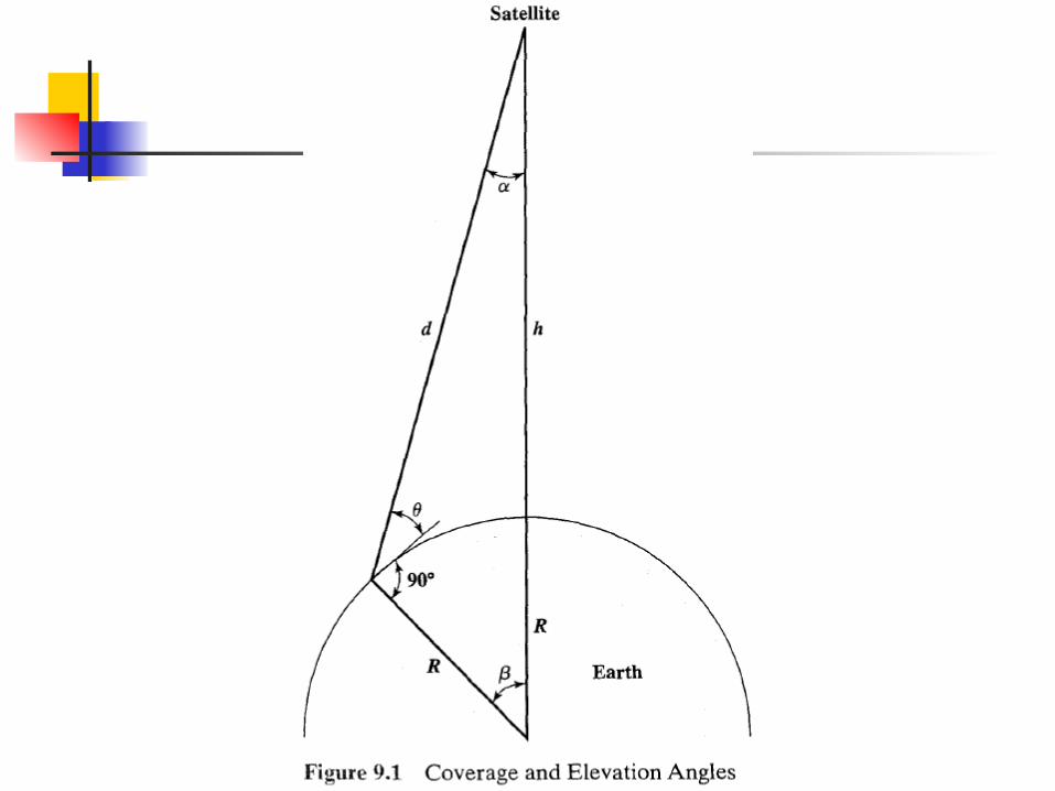
Geometry Terms Elevation angle - the angle from the horizontal to
the point on the center of the main beam of the antenna when the antenna is pointed directly at the satellite
Coverage angle - the measure of the portion of the earth's surface visible to the satellite
According to the figure, what are the elevation angle and the coverage angle?
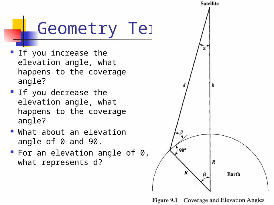
Geometry Terms If you increase the elevation
angle, what happens to the coverage angle?
If you decrease the elevation angle, what happens to the coverage angle?
What about an elevation angle of 0 and 90.
For an elevation angle of 0, what represents d?

Geometry Terms If you decrease the elevation
angle, what happens to the distance traversed by the signal in the atmosphere?
What is the maximum coverage area of the satellite?
Minimum Elevation Angle Minimum elevation angle To obtain maximum satellite
coverage, we would like to use an elevation angle of 0 , which would enable the satellite's coverage to extend to the
optical horizon from the satellite in all directions Reasons affecting minimum elevation angle of earth station’s
antenna (>0o) Buildings, trees, and other terrestrial objects block the line of
sight=> attenuation by absorption or mutlipath Atmospheric attenuation is greater at low elevation angles =>
the signal traverses the atmosphere for longer distances the smaller the elevation angle
The coverage area diameter is 2*R*coverage_angle
GEO Orbit circular orbit If Altitude: 35,863 km above the earth's
surface And rotates in the equatorial plane of the
earth, Then rotate at exactly the same angular speed
as the earth =>What is the orbit period?? => What is the visibility duration??

GEO Orbit circular orbit If Altitude: 35,863 km above the earth's
surface And rotates in the equatorial plane of the
earth, Then rotate at exactly the same angular speed
as the earth =>will remain above the same spot on the
equator as the earth rotates
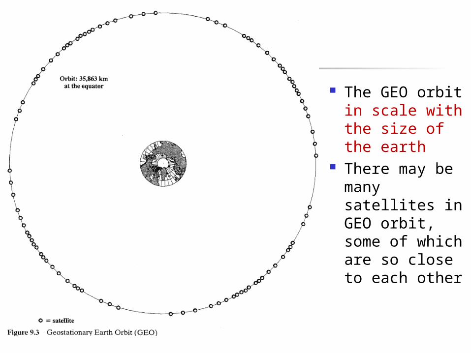
The GEO orbit in scale with the size of the earth
There may be many satellites in GEO orbit, some of which are so close to each other
GEO Orbit Advantages of the GEO orbit
Satellite is stationary relative to the earth (no doppler shift)
Tracking of the satellite is simplified by the earth stations
High coverage area, roughly a fourth of the earth; three satellites in geostationary orbit separated by 120
degree cover most of the inhabited portions of the entire
earth excluding only the areas near the north and south poles.
GEO Orbit Disadvantages of the GEO orbit
Weak signal after traveling over 35,000 km Polar regions are poorly served by geostationary satellites Signal sending delay is substantial
Speed of light = 3 10^8 m/s Propagation delay?? Round Trip Delay for two locations on
earth under the satellite? High coverage area: For point to multipoint
applications such as broadcasting TV programs this is desirable
For point to point communication it is very wasteful of spectrum=> that is why we need LEOs and MEOs
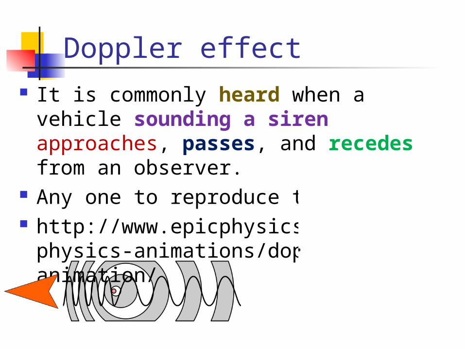
Doppler effect It is commonly heard when a vehicle sounding a
siren approaches, passes, and recedes from an observer.
Any one to reproduce the sound? http://www.epicphysics.com/physics-animations/doppler-effect-animation/
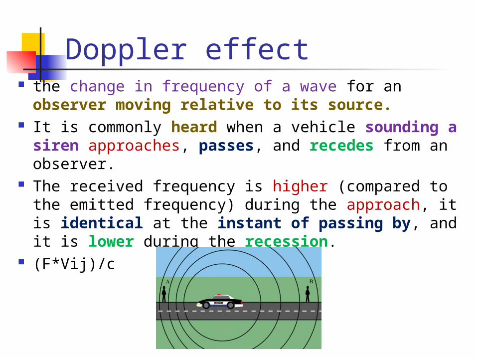
Doppler effect the change in frequency of a wave for an observer
moving relative to its source. It is commonly heard when a vehicle sounding a siren
approaches, passes, and recedes from an observer. The received frequency is higher (compared to the
emitted frequency) during the approach, it is identical at the instant of passing by, and it is lower during the recession.
(F*Vij)/c
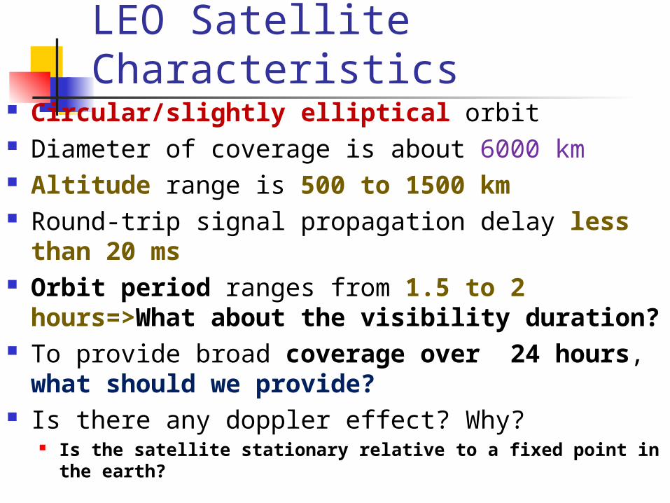
LEO Satellite Characteristics Circular/slightly elliptical orbit Diameter of coverage is about 6000 km Altitude range is 500 to 1500 km Round-trip signal propagation delay less than 20 ms Orbit period ranges from 1.5 to 2 hours=>What about
the visibility duration? To provide broad coverage over 24 hours, what should
we provide? Is there any doppler effect? Why?
Is the satellite stationary relative to a fixed point in the earth?
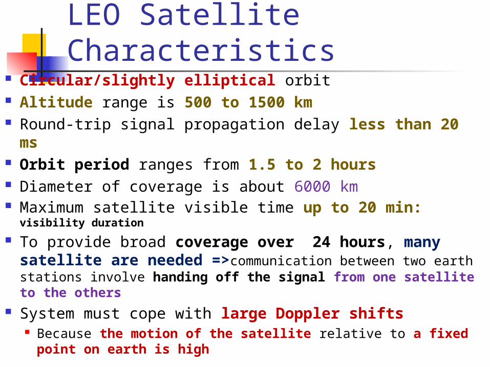
LEO Satellite Characteristics Circular/slightly elliptical orbit Altitude range is 500 to 1500 km Round-trip signal propagation delay less than 20 ms Orbit period ranges from 1.5 to 2 hours Diameter of coverage is about 6000 km Maximum satellite visible time up to 20 min: visibility duration
To provide broad coverage over 24 hours, many satellite are needed =>communication between two earth stations involve handing off the signal from one satellite to the others
System must cope with large Doppler shifts Because the motion of the satellite relative to a fixed point on
earth is high
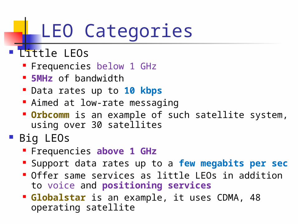
LEO Categories Little LEOs
Frequencies below 1 GHz 5MHz of bandwidth Data rates up to 10 kbps Aimed at low-rate messaging Orbcomm is an example of such satellite system, using over 30
satellites Big LEOs
Frequencies above 1 GHz Support data rates up to a few megabits per sec Offer same services as little LEOs in addition to voice and
positioning services Globalstar is an example, it uses CDMA, 48 operating satellite

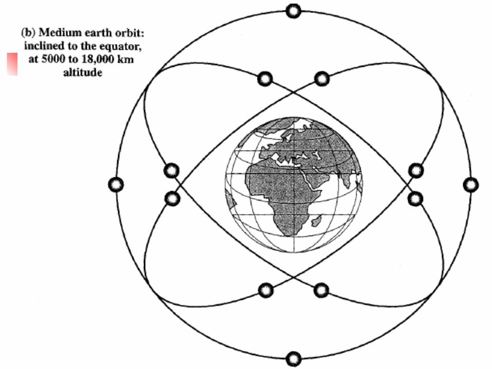
MEO Satellite Characteristics Circular orbit at an altitude in the range of 8000 to
18,000 km Orbit period of 5 to 10 h Diameter of coverage is 12,000 to 15,000 km Round trip signal propagation delay less than 50 ms Maximum satellite visible time is a few hours (2 to 8
hours) Propagation delay and required power are greater
than those for LEO but less than those for GEO
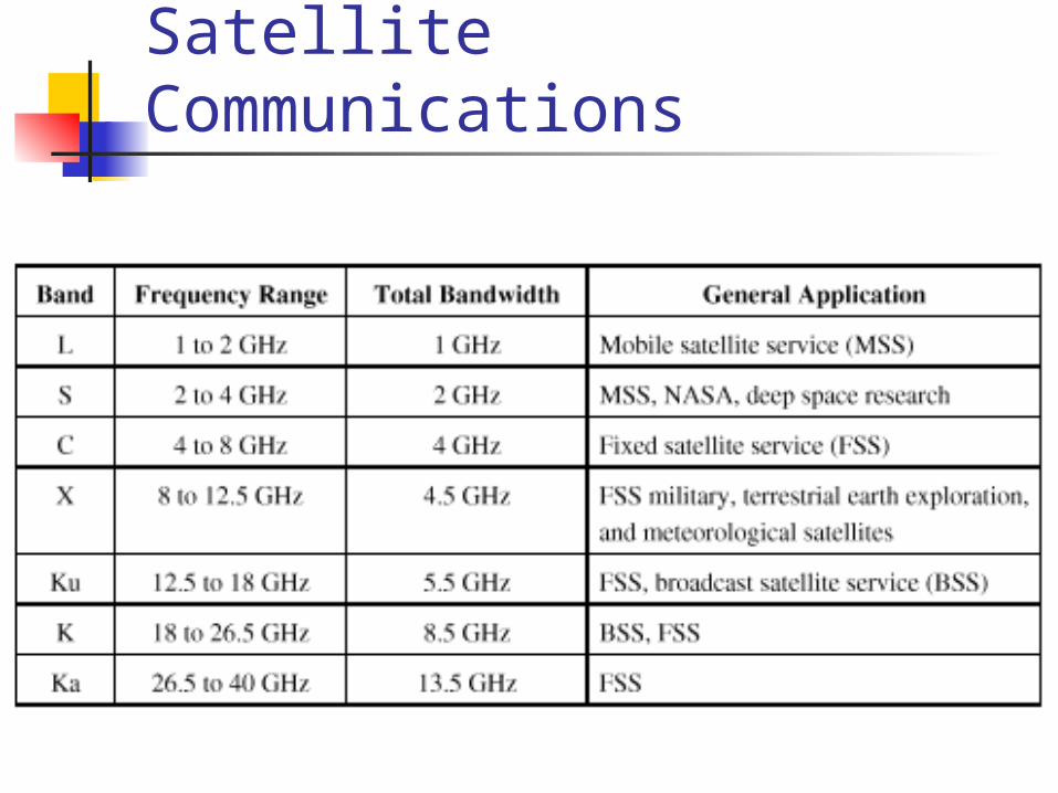
Frequency Bands Available for Satellite Communications
Frequency Bands Available for Satellite Communications
For any given frequency allocation for a service, there is an allocation of an uplink band and a downlink band,
the uplink band always of higher frequency. The higher frequency suffers greater
spreading, or free space loss, than its lower frequency counterpart.
The earth station is capable of higher power, which helps to compensate for the poorer performance at higher frequency.

Satellite Link Performance Factors
Distance between satellite antenna and earth station antenna
The higher the frequency, the greater the loss Takes into account that electromagnetic waves spread out into spherical radiation
pattern as they propagate through space due to diffraction For downlink, terrestrial distance between earth station antenna and “aim
point” of satellite Displayed as a satellite footprint (Figure 9.6)
Atmospheric attenuation Affected by oxygen, water, angle of elevation, and higher frequencies The smaller the elevation angle the greater the atmospheric absorption The higher the frequency the greater the effect
dB 56.147log20log20 dfLdb

Satellite Footprint At microwave frequencies, which are used in satellite
communications, highly directional antennas are used. Thus, the signal from a satellite is not isotropically broadcast
but is aimed at a specific point on the earth, depending on which area of coverage is desired.
The center point of that area will receive the highest radiated power, and the power drops off as you move away from the center point in any direction.
This effect is typically displayed in a pattern known as a satellite footprint; an example is shown in Figure 9.6.
The satellite footprint displays the effective radiated power of the antenna at each point, taking into account the signal power fed into the antenna and the directionality of the antenna.

Satellite Footprint
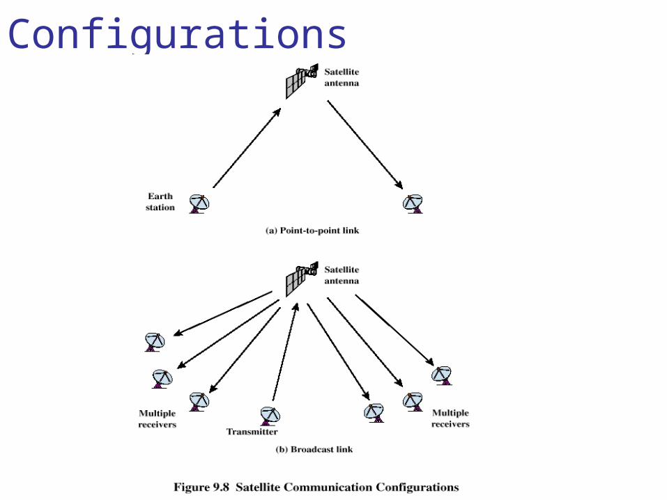
Satellite Network Configurations
Capacity Allocation Strategies a GEO satellite will handle a rather large bandwidth
(e.g., 500 MHz) and divide it into a number of channels of smaller bandwidth (e.g., 40 MHz).
Within each of these channels, there is a capacity allocation task to be performed. => multiplexing Frequency division multiple access (FDMA) Time division multiple access (TDMA) Code division multiple access (CDMA)

Frequency-Division Multiplexing FDM
The overall capacity of a communications satellite is divided into a number of channels.
Further capacity allocation is carried out within each channel. Exp: Galaxy satellites
GEO satellites Uses C band frequencies => 500 MHz bandwidth Broken into 24 40-Mhz channels Each frequency assignment is used by two carriers with orthogonal
polarization Each 40-MHz channel includes a 4-MHz guard-band so each channel is
actually 36MHZ wide

Frequency-Division Multiplexing FDM
Frequency-Division Multiplexing FDM
Example of an FDM scheme, which is typical of GEO communications satellites;
this particular allocation is used in the Galaxy satellites from PanAmSat.
PanAmSat is the largest satellite operator in the world. It is a private corporation providing satellite communications capacity worldwide.
The satellite uses C band frequencies (4-8GHz) Provides a 500-MHz bandwidth, which is broken up into 24 40-MHz
channels. Each 40-MHz channel includes a 4-MHz guardband, so each channel
is actually 36 MHz wide.
Frequency-Division Multiplexing FDM Alternative uses of channels in point-to-point
configuration 1200 voice-frequency (VF) voice channels One 50-Mbps data stream 16 channels of 1.544 Mbps each 400 channels of 64 kbps each 600 channels of 40 kbps each
Frequency-Division Multiple Access FDMA
Each satellite channel is divided into a number of smaller channels (sub-channels) which in turn carries a number of voice frequency.
The ability of multiple earth stations to access the same channel is referred to FDMA
Frequency-division multiplexing (FDM) is also distinct from FDMA.
FDM is a physical layer technique that combines and transmits low-bandwidth channels through a high-bandwidth channel.
FDMA, on the other hand, is an access method in the data link layer.
FDMA Factors which limit the number of subchannels
provided within a satellite channel via FDMA Thermal noise Intermodulation noise Crosstalk
Noise Terminology Intermodulation noise – occurs if signals with
different frequencies share the same medium Interference caused by a signal produced at a frequency that is
the sum or difference of original frequencies the mixing of signals at frequencies f1and f2 might produce
energy at the frequency f1+f2. This derived signal could interfere with an intended signal at the frequency f1+f2.
Crosstalk – unwanted coupling between signal paths experienced by anyone who, while using the telephone, has
been able to hear another conversation
Forms of FDMA Fixed-assignment multiple access (FAMA)
The assignment of capacity within the channel is distributed in a fixed manner among multiple stations
Demand may fluctuate Results in the significant underuse of capacity
Demand-assignment multiple access (DAMA) Capacity assignment is changed as needed to respond
optimally to demand changes among the multiple stations
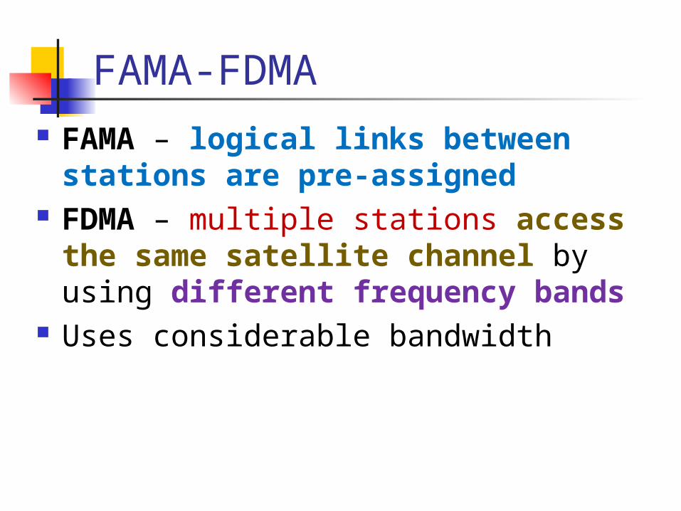
FAMA-FDMA FAMA – logical links between stations are
pre-assigned FDMA – multiple stations access the same
satellite channel by using different frequency bands
Uses considerable bandwidth

FAMA-FDMA Figure 9.11 is a specific example of FAMA-FDMA, with seven
earth stations sharing the 36-MHz uplink capacity; a similar downlink diagram can be drawn. Station A is assigned the 5-MHz bandwidth from 6237.5 to
6242.5 MHz, in which it can transmit 60 VF channels using FDM-FM.
That is, FDM is used to carry the 60 channels, and FM is used to modulate the channels onto the carrier frequency of 6240 MHz.
A has traffic for other stations as follows: 24 channels to B, 24 channels to D, and 12 channels to E.
The remaining spectrum of the 36-MHz channel is divided among the other earth stations according to their traffic needs.
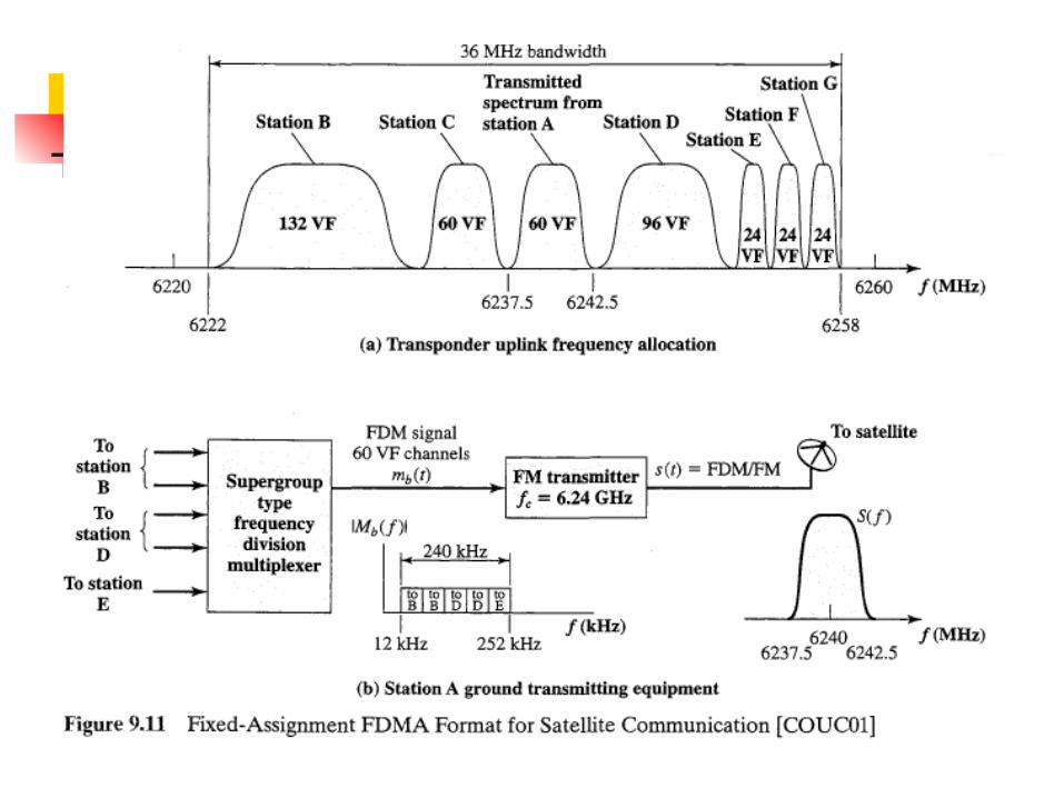

FAMA-FDMA Considerable bandwidth is used. For example, station A has 60 VF channels to transmit,
which occupy only 240 kHz (one VF channel = 4 kHz). Yet the satellite bandwidth allocation is 5 MHz. This is due to the use of FM (rather than AM)
to maintain signal over the long distance of the satellite link and
to minimize satellite power requirements.
FAMA-FDMA The FAMA-FDMA scheme just described is not
efficient. Typically, in the C band, each channel has a usable
bandwidth of 36 MHz. One INTELSAT FDMA scheme divides this into 7 5-MHz blocks, each of which carries a group of 60 VF channels, for a total of 420 channels.
When the bandwidth is divided into 14 2.5-MHz sub-channels, a group of 24 VF channels can be carried in each channel for a total of 336 channels.
FAMA-FDMA It turns out to be more efficient to avoid
groupings altogether and simply to divide the 36-MHz bandwidth into individual VF channels. This technique is known as single channel per carrier (SCPC).
Single channel per carrier (SCPC) – bandwidth divided into individual VF channels Suffers from inefficiency of fixed assignment
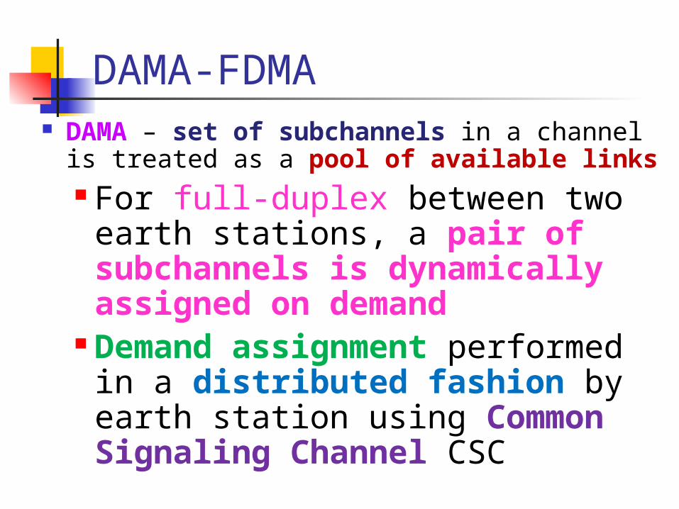
DAMA-FDMA DAMA – set of subchannels in a channel is treated as
a pool of available links For full-duplex between two earth
stations, a pair of subchannels is dynamically assigned on demand
Demand assignment performed in a distributed fashion by earth station using Common Signaling Channel CSC
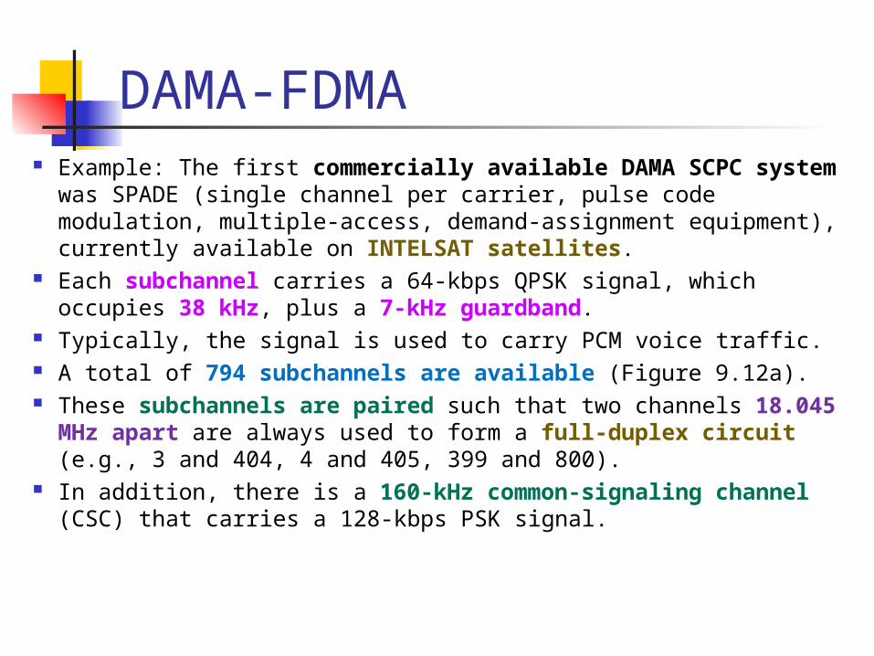
DAMA-FDMA Example: The first commercially available DAMA SCPC system was
SPADE (single channel per carrier, pulse code modulation, multiple-access, demand-assignment equipment), currently available on INTELSAT satellites.
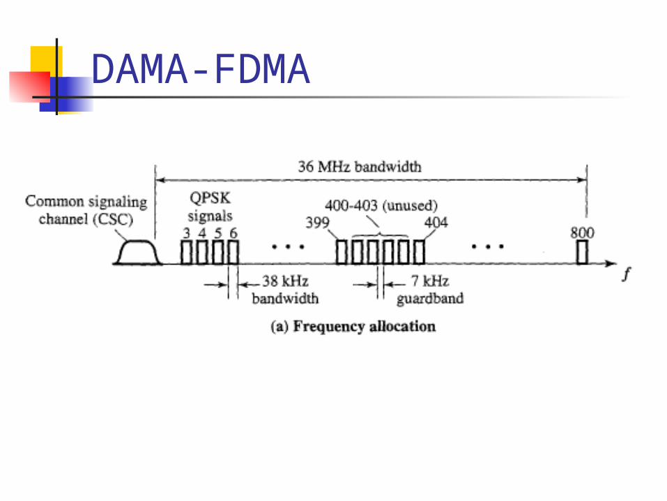
Each subchannel carries a 64-kbps QPSK signal, which occupies 38 kHz, plus a 7-kHz guardband.
Typically, the signal is used to carry PCM voice traffic. A total of 794 subchannels are available (Figure 9.12a). These subchannels are paired such that two channels 18.045 MHz apart are
always used to form a full-duplex circuit (e.g., 3 and 404, 4 and 405, 399 and 800).
In addition, there is a 160-kHz common-signaling channel (CSC) that carries a 128-kbps PSK signal.
DAMA-FDMA
Reasons for Increasing Use of TDM Techniques
Cost of digital components continues to drop Advantages of digital components
Use of error correction Increased efficiency of TDM
Lack of intermodulation noise

FAMA-TDMA Operation Transmission in the form of repetitive sequence of
frames Each frame is divided into a number of time slots Each slot is dedicated to a particular transmitter
Earth stations take turns using uplink channel Sends data in assigned time slot
Satellite repeats incoming transmissions Broadcast to all stations
Stations must know which slot to use for transmission and which to use for reception

FAMA-TDMA Uplink

FAMA-TDMA Downlink

Reference burst : to identify the beginning of the frame for synchronization purposes
Appendix

Ways to CategorizeCommunications Satellites Coverage area
Global, regional, national Service type
Fixed service satellite (FSS) Broadcast service satellite (BSS) Mobile service satellite (MSS)
General usage Commercial, military, amateur, experimental
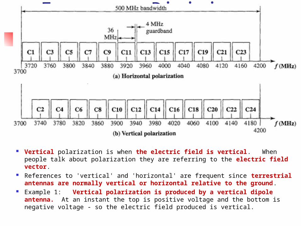
Frequency-Division Multiplexing
Vertical polarization is when the electric field is vertical. When people talk about polarization they are referring to the electric field vector.
References to 'vertical' and 'horizontal' are frequent since terrestrial antennas are normally vertical or horizontal relative to the ground.
Example 1: Vertical polarization is produced by a vertical dipole antenna. At an instant the top is positive voltage and the bottom is negative voltage - so the electric field produced is vertical.