Embed Size (px)
Citation preview
SARAF phase-I
beam operation status
Arik Kreisel
September 2014
LINAC14
Soreq

Outline
Introduction
Beam operation
Problems and solutions (LINAC12 - LINAC14)
From pilot beam to full intensity beam
Operating the RFQ with a high duty cycle deuteron beam
Super conducting cavities
Beam dump
High power targets
Physics at SARAF Phase-I
Example: natCu(d,x) cross section
2

SARAF – Soreq Applied Research Accelerator Facility
To modernize the source of neutrons at Soreq and extend neutron based research and applications.
To develop and produce radioisotopes for bio-medical applications.
To enlarge the experimental nuclear science infrastructure and promote the research in Israel.
3

SARAF Accelerator Complex
Phase II Phase I - 2009
4
Parameter Value Comment
Ion Species Protons/Deuterons M/q ≤ 2
Energy Range 5 – 40 MeV Variable energy
Current Range 0.04 – 5 mA CW (and pulsed)
Operation 6000 hours/year
Reliability 90%
Maintenance Hands-On Very low beam loss
176 MHz

SARAF Phase I – Upstream View
EIS LEBT
RFQ MEBT
PSM
Proton/Deuteron
ECR ion source 20 keV/u,
beam transport
4 m long, 250 kW
4-rod RFQ
65 cm long
MEBT 4.5 K superconducting
module housing 6 b0=0.09
bulk Nb HWRs, 0.85 MV
each and 3 6T solenoids in a
separated vacuum, 2.5 m
long cryostat
SARAF Phase I – Upstream View
5
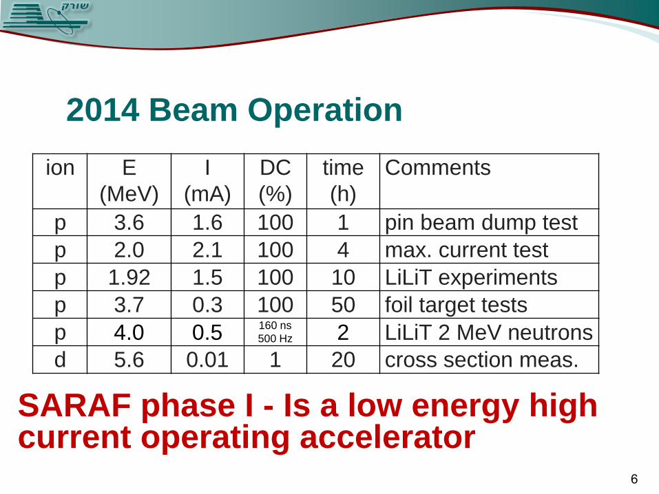
2014 Beam Operation
6
ion E
(MeV)
I
(mA)
DC
(%)
time
(h)
Comments
p 3.6 1.6 100 1 pin beam dump test
p 2.0 2.1 100 4 max. current test
p 1.92 1.5 100 10 LiLiT experiments
p 3.7 0.3 100 50 foil target tests
p 4.0 0.5 160 ns
500 Hz 2 LiLiT 2 MeV neutrons
d 5.6 0.01 1 20 cross section meas.
SARAF phase I - Is a low energy high current operating accelerator

From pilot beam to intense beam Challenge – At present beam intensity
ramping is done by manipulation of LEBT
parameters and beam duty cycle is done
by pulsing the ion source. Measuring of
CW beam profiles with a non-destructive
residual gas profiler monitor showed that
such a methods lead to variation in the
beam optics.
Solution – A beam chopper was
introduced at the LEBT and incorporated
into the machine safety system. It still
needs to be verified that working with the
EIS in CW mode and ramping up beam
power by changing the chopper duty cycle
will lead to a more stable beam and
smaller changes in beam optics.
Minimum chopper pulse length of
160 ns as measured by BPM and a FFC
7 SPIRAL 2 chopper design: A. Caruso et al. LINAC 2008.
Residual Gas Monitor test: E. Gueroult et al. JINST 2013.

Operating the RFQ with a CW deuteron beam
Challenge – Operating the RFQ in the
range of 250-260 kW (65 kV voltage),
required for CW deuteron operation.
Possible solutions –
1. Improve heat removal, vacuum, RF
coupling and proceed with aggressive
conditioning to enable operation of
intense deuteron beam at Phase I;
2. Modify rod structure toward lower
energy (1.3 MeV/u 200 kW) with present
RFQ; [A. Shor SNRC report #4242 (2013)].
RFQ conditioning campaign was started to
establish the status of the current RFQ and
the feasibility to operate it as is with 250 kW
or with modified rods at 180-200 kW. 8
176 MHz, 65 kW/m,
1.5 MeV/u
[P. Fischer et al., EPAC06]

December 2013 RFQ conditioning campaign
The rod structure and the coupler ceramics were cleaned and maintenance on the RFQ-RF amplifier was performed before the campaign
It was still extremely difficult to raise the field up to deuteron operation level. It took a week (50 net hours) to reach the required field value even for the shortest RF pulses.
After the breakthrough, progress was quite fast, and 30% duty cycle was reached within three days
9
Several improvements were performed in order to bring the RFQ to its specified power [L. Weissman et al. JINST T05004 (2014)], however:
The fact that the RFQ was not operated at the deuterons field for two years resulted in deterioration of its performance
goal

May-June 2014 RFQ conditioning campaign The main objective of the campaign, to
demonstrate RFQ operation in the range of 180-200 kW CW, was achieved.
The emphasis in the campaign was on safe RFQ operation in order not to disrupt the accelerator schedule. As a result, the conditioning campaign was not as “aggressive” as it could have been.
Record levels of RFQ operation (250 kW at 50 % DC and 200 kW CW) were achieved in a relatively short time
Average time of operation without trip at 250 kW, 50 % and 20% duty cycle, were 10-15 min and 2-3 hours, respectively .The RFQ stability improved with continuation of the campaign.
A scope screenshot of the RFQ signals during
operation at 250 kW, 50 % duty cycle 10

The Superconducting cavities sensitivity
The main problem of the SARAF Phase-I superconducting cavities is their susceptibility to mechanical deformation:
The cavities are sensitive to fluctuations in the Liquid He pressure (60 Hz/mbar compared to the designed value 15 Hz/mbar). The ±1.5 mbar pressure variation of the cryogenic system is manifested by frequency detuning that exceeds the cavities loaded bandwidth of 130 Hz.
The cavities are sensitive to Lorentz detuning. Intense ponderomotive oscillations appear at certain power on the high frequency side. These oscillations hinder locking of the cavities at high RF power values.
11

Improving cavity
rigidity
Suggested solution - Increase
the rigidity of the tuning fog and
add ribs at the vicinity of the
beam line. This should reduce
the sensitivity of the HWR to
helium pressure by a factor of ~3
100 110 120 130 140 150 160 170 180 190 200-100
-80
-60
-40
-20
0
20
40
60
80
100
Time[Sec]
Fre
quency D
etu
nin
g [
Hz]
Frequency Detuning
45 sec
Measured sensitivity of 60 Hz/mBar in collaboration with J. Delayen and K. Davis (JLab)
[L. Weissman LINAC 2010]
21 Hz/mBar
For more details please visit poster
MOPP134 by J. Rodnizki
12
Tuning fog
Ribs
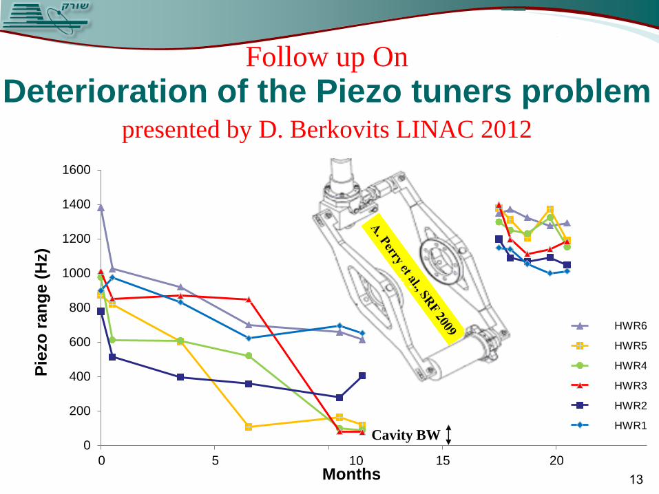
Follow up On
Deterioration of the Piezo tuners problem presented by D. Berkovits LINAC 2012
1600
1400
1200
1000
800
600
400
200
Cavity BW 0
0 5 10 Months
15 20
Pie
zo
ran
ge (
Hz)
HWR6
HWR5
HWR4
HWR3
HWR2
HWR1
13

Solution follow up from LINAC12
During the 2012 winter-spring maintenance period, the tuners were replaced by another type of piezo activators (Pst1000), which operate at higher voltage and have superior mechanical strength.
LV PZT HV PZT 14
The tuning ranges of the new piezos are measured regularly since May 2012. So far, no significant degradation of the tuning ranges has been observed.
15
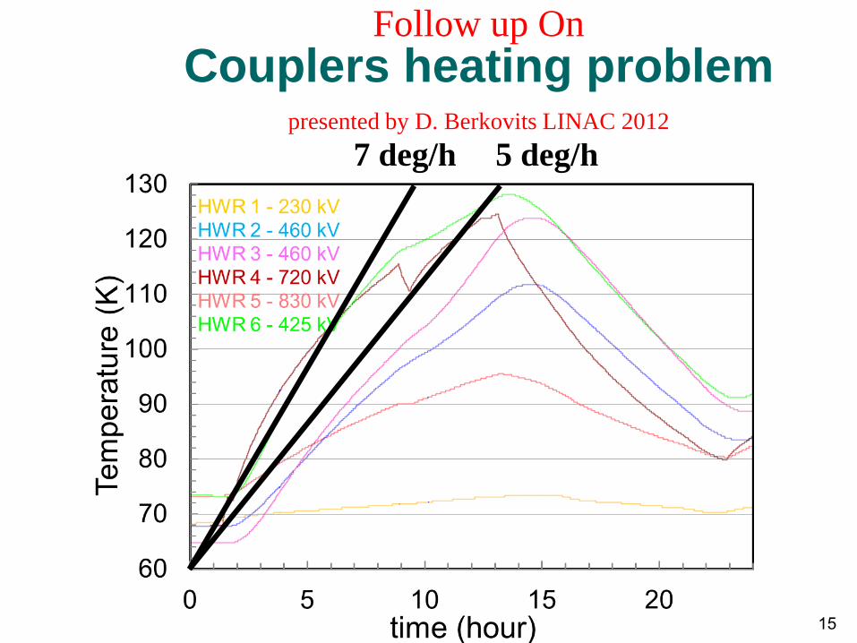
5 deg/h 7 deg/h
Follow up On
Couplers heating problem presented by D. Berkovits LINAC 2012

inside coupler multipacting
Cold window
70OK
Copper Cooling strip
~ 4OK
10-11 mbar
10-7 mbar
Temperature
sensor
DC
Bias
Solution - a DC bias voltage
between the inner and outer
conductors of the coupler
16
cause of heating:

Implementation - DC bias-T element
C1
ATC100E391
C2
ATC100E391
C3
ATC100E391
C4
ATC100E391
J1
1 5/8"EIA
J2
1 5/8" EIA
C510 nF
L1
8 t
# 2mm
J3BNC
1 5/8" EIA line 1 5/8" EIA line
RF Box
Bias
RFoutRFin
For full details please visit poster THPP132
by Boaz Kaizer on Thursday, 16:00-18:00, poster session
17

DC Bias-T test
At 600 kV (240 W forward power )
acceleration voltage:
Without bias - 10 K/h
With 900 V bias - 0.6 K/h
[J. Rodnizki SRF 2013]
[B. Kaizer LINAC 2014] 18

RF couplers temperature with Bias-T
1 kV bias no bias
[L. Weissman INS27 (2014)] 19

Tungsten beam dump blistering problem The 250 micron Tungsten sheet fused to a water cooled cooper plate beam dump
exhibits remarkably low prompt and residual radiation at phase I beam energies.
However, it suffers from severe blistering effects. (Generation 2 and 3).
150 mm
[L. Weissman RuPAC 2012] 20

Alternative porous heavy metal beam dump
A desirable moveable beam dump should enable long and reliable operation of the accelerator at the highest beam power, with minimal prompt and residual radiation
A similar beam dump (generation 4), made of copper free heavy metal instead of pure tungsten with high porosity of the heavy metal solved the blistering problem. Up to 4 kW of beam intensity was applied on this dump for many hours. The beam dump did not exhibit any blistering. Long term operation of this beam dump still leads to severe activation due to low-Z metal content in heavy metal.
21

The Tungsten Pin Beam dump
The current SARAF beam dump (generation 5) is made from tungsten pins inserted in a water cooled copper block. The pins are arranged in such a way that beam does not impinge on the copper. The absorbed beam power is irradiated by the hot pins and reabsorbed by the water cooled environment. This beam dump is designed for up to 20 kW of beam power. It is not susceptible to blistering due to efficient diffusion of hydrogen from the hot directed pins.
Water cooling channels
22
Directed
viewport

2 kW of beam energy was successfully applied to this beam dump prototype [A. Arenshtam JINST 2013]
The first version of a 80 mm diameter pins dump was tested at SARAF with 5.7 kW, 3.6 MeV protons. It emitted lower gamma radiation relative to the previous beam dump and low neutrons radiation (~ 10 mrem/h at one meter distance from the dump) was measured. The heat from the pins, which is irradiated in visible light, enables this beam dump to serve for beam visualisation
Testing the Tungsten Pin Beam dump
23

Ramping up the current
0.2 mA 0.4 mA 0.8 mA 1 mA
Operating with the Tungsten Pin Beam dump
Varying quads while observing 0.3 mA beam (0.65 kW)
24
80 mm

Requirements from a strong neutron source from a low energy beam Intense neutron source
at low energies means high current
At low energy the target has to be in the accelerator vacuum
That means difficult heat removal
The SARAF solution is a Liquid Lithium jet Target (LiLiT) 7Li(p,n)
25
Jet
chamber
liquid
lithium
beam
[S. Halfon RSI 2014]

LiLiTBenpLi
77),(
Eth=1.881 MeV
SARAFEp = 1.912 MeV En ˜ 30 keV
TARGET
SrnSr9190
),(
LiLiTBenpLi
77),(
Eth=1.881 MeV
SARAFEp = 1.912 MeV En ˜ 30 keV
TARGET
SrnSr9190
),(
0 20 40 60 80 1000
2x10⁸
4x10⁸
6x10⁸
8x10⁸
dn/d
E (
1/k
eV
)
Neutron energy (keV)
2 mA, 1912 keV proton beam
fit )( kT
E
eE
kT = 26 keV
2.4*1010 n/sec*mA
[G. Feinberg et al., Nucl Phys A827(2009)]
protons @ 1.91 MeV
Li jet
creates in lab stellar neutron
spectra with T=300 million
degrees ~ kT = 25 keV neutron
flux approaching ~1011 n/sec
Astrophysics nucleo-synthesis
26
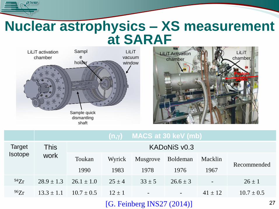
Nuclear astrophysics – XS measurement at SARAF
(n,) MACS at 30 keV (mb)
Target
Isotope This
work
KADoNiS v0.3
Toukan
1990
Wyrick
1983
Musgrove
1978
Boldeman
1976
Macklin
1967 Recommended
94Zr 28.9 ± 1.3 26.1 ± 1.0 25 ± 4 33 ± 5 26.6 ± 3 - 26 ± 1
96Zr 13.3 ± 1.1 10.7 ± 0.5 12 ± 1 - - 41 ± 12 10.7 ± 0.5
Sampl
e
holder
LiLiT
vacuum
window
LiLiT activation
chamber
Sample quick
dismantling
shaft
LiLiT Activation
chamber
LiLiT
chamber
Proton
beam
[G. Feinberg INS27 (2014)] 27
Activation of natural copper by deuterons at energy of a few MeV is of the special interest, as Radio Frequency Quadrupole (RFQ) injectors consist of copper electrodes
Although the nuclear cross-section is low, beam loss in this accelerator component is expected to be high compared to that of the superconducting LINAC
For example, in the IFMIF RFQ, deuteron beam losses in the energy ranges of 3-4 MeV and 4-5 MeV are expected to be as high as 0.2 mA and 0.1 mA, respectively [S. Simakov, Fus. Eng,
and Des. (2008)]
For d+Cu cross section measurements ten values of deuteron energy from 2.77 MeV to 5.62 MeV were used in irradiations. The lowest deuteron energy was achieved by setting the second cavity at a deceleration phase
Physics at SARAF – deuterons on copper
28

63Cu(d,p)64Cu measurement at SARAF
Half life τ=13 hours
29
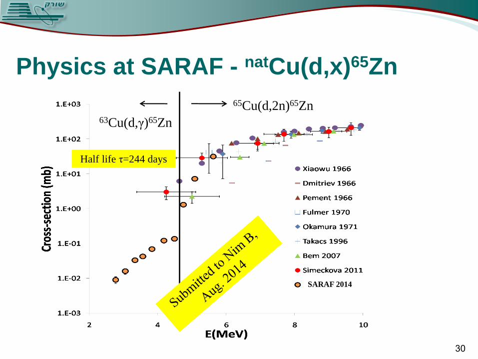
Physics at SARAF - natCu(d,x)65Zn
SARAF 2014
65Cu(d,2n)65Zn 63Cu(d,γ)65Zn
Half life τ=244 days
30
Summary
Significant progress at SARAF phase-I was achieved recently, while overcoming hurdles and bridging gaps of knowledge.
Beam operation using the chopper installed in the LEBT and integrated into the machine safety is now being tested
Operation of RFQ at deuteron duty cycle of 50% at 250 kW and with 200 kW CW was demonstrated.
New DC bias elements were connected to the coupler, which significantly reduced coupler heating due to multipacting
A new tungsten pin beam dump was installed and tested
The LiLiT target was installed, operated and first scientific experiments were performed
A program for measuring deuteron-induced cross-section was launched
31

THANK YOU!
A. Kreisel, L. Weissman, A. Arenshtam, Y. Ben Aliz, D. Berkovits, Y. Buzaglo, O. Dudovich, Y. Eisen, I. Eliyahu, G. Feinberg, I. Fishman, I. Gertz, A. Grin, S. Halfon, Y. Haruvy, T. Hirsh, D. Hirschmann, Z. Horvitz, B. Kaizer, D. Kijel, Y. Luner, I. Mor, J. Rodnizki, G. Shimel, A. Shor, I. Silverman, D. Vartsky and E. Zemach
32
ion E
(MeV)
I
(mA)
DC
(%)
time
(h)
Comments
p 3.6 1.6 100 1 pin beam dump test
p 2.0 2.1 100 4 max. current test
p 1.92 1.5 100 10 LiLiT experiments
p 3.7 0.3 100 50 foil target tests
p 4.0 0.5 160 ns
500 Hz 2 LiLiT 2 MeV neutrons
d 5.6 0.01 1 20 cross section meas.