Embed Size (px)
Citation preview
© 2008 Cisco Systems, Inc. All rights reserved. Cisco Confidential Presentation_ID 1
SANOG 14: MPLS Network Design and Deployment Workshop Agenda Srini Irigi, SPG TME, Cisco Systems, CCIE 6147 Jonny Martin, Internet Analyst, PCH
© 2008 Cisco Systems, Inc. All rights reserved. Cisco Confidential Presentation_ID 2
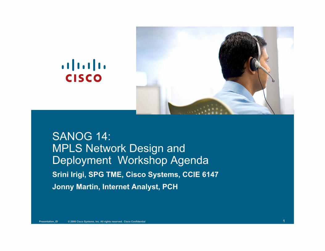
Workshop Structure
© 2008 Cisco Systems, Inc. All rights reserved. Cisco Confidential Presentation_ID 3
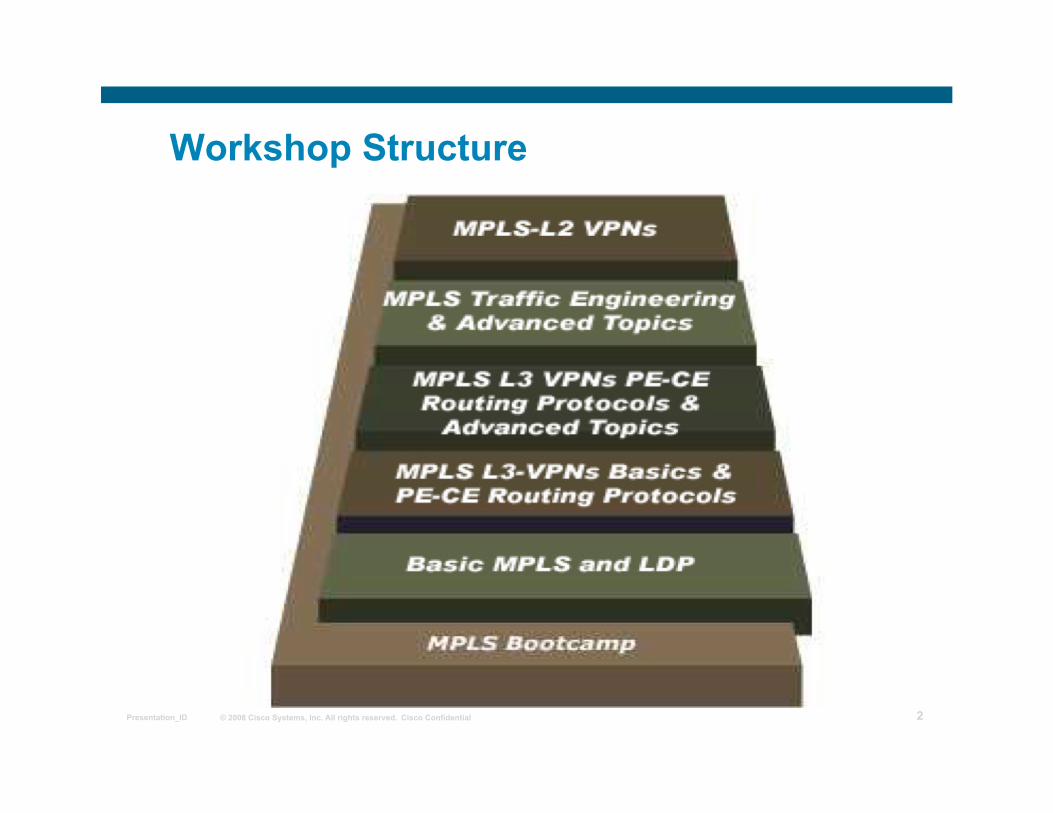
Day 1 Agenda
Day 1 Modules Why MPLS is needed ??? How labels are advertised and stored
What protocols are used to distribute labels Lab Overview & Initial Configuration Lab
LUNCH
LDP: LDP concepts, configuration and troubleshooting MPLS Basics Configuration Lab
© 2008 Cisco Systems, Inc. All rights reserved. Cisco Confidential Presentation_ID 4
Day 2 Agenda
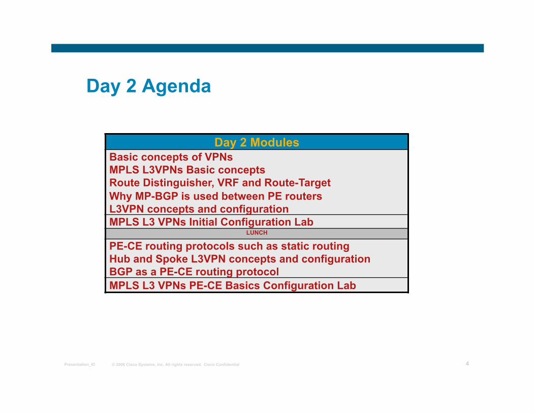
Day 2 Modules Basic concepts of VPNs MPLS L3VPNs Basic concepts Route Distinguisher, VRF and Route-Target Why MP-BGP is used between PE routers L3VPN concepts and configuration MPLS L3 VPNs Initial Configuration Lab
LUNCH
PE-CE routing protocols such as static routing Hub and Spoke L3VPN concepts and configuration BGP as a PE-CE routing protocol MPLS L3 VPNs PE-CE Basics Configuration Lab
© 2008 Cisco Systems, Inc. All rights reserved. Cisco Confidential Presentation_ID 5
Day 3 Agenda
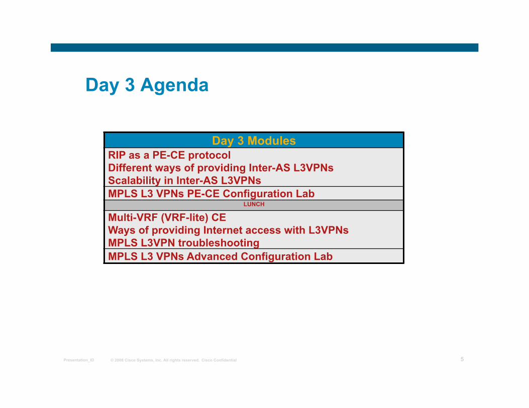
Day 3 Modules RIP as a PE-CE protocol Different ways of providing Inter-AS L3VPNs Scalability in Inter-AS L3VPNs MPLS L3 VPNs PE-CE Configuration Lab
LUNCH
Multi-VRF (VRF-lite) CE Ways of providing Internet access with L3VPNs MPLS L3VPN troubleshooting MPLS L3 VPNs Advanced Configuration Lab
© 2008 Cisco Systems, Inc. All rights reserved. Cisco Confidential Presentation_ID 6
MPLS workshop
Configuring RIP as a Routing Protocol Between PE and CE Routers
© 2008 Cisco Systems, Inc. All rights reserved. Cisco Confidential Presentation_ID 7
Outline
Configuring RIP PE-CE Routing
Avoiding Routing Loops with RIP as PE-CE Protocol
© 2008 Cisco Systems, Inc. All rights reserved. Cisco Confidential Presentation_ID 8
Configuring RIP PE-CE Routing
• A routing context is configured for each VRF running RIP.
• RIP parameters have to be specified in the VRF.
• Some parameters configured in the RIP process are propagated to routing contexts (for example, RIP version).
• Only RIPv2 is supported.
• RIP may work but does not support VLSM (Variable Length Subnet Mask)
© 2008 Cisco Systems, Inc. All rights reserved. Cisco Confidential Presentation_ID 9
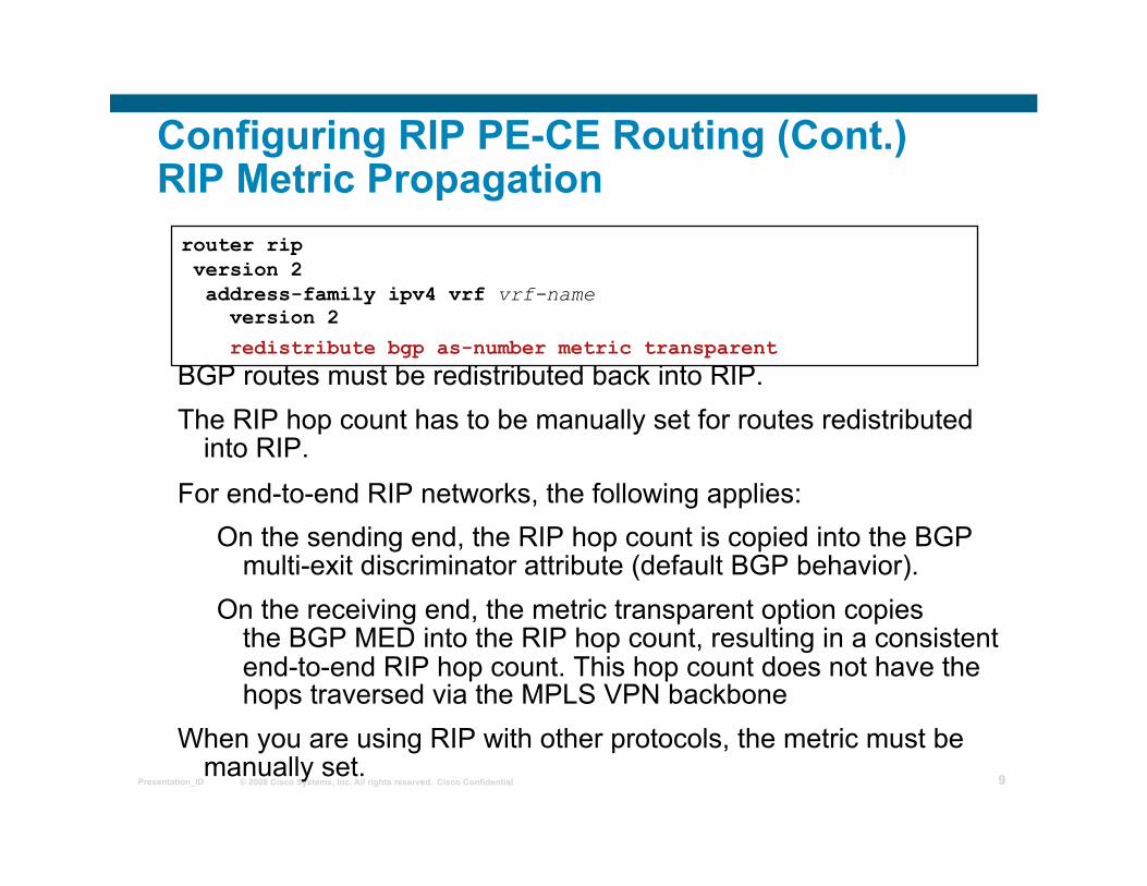
router rip version 2 address-family ipv4 vrf vrf-name version 2 redistribute bgp as-number metric transparent
Configuring RIP PE-CE Routing (Cont.) RIP Metric Propagation
BGP routes must be redistributed back into RIP. The RIP hop count has to be manually set for routes redistributed
into RIP. For end-to-end RIP networks, the following applies:
On the sending end, the RIP hop count is copied into the BGP multi-exit discriminator attribute (default BGP behavior).
On the receiving end, the metric transparent option copies the BGP MED into the RIP hop count, resulting in a consistent end-to-end RIP hop count. This hop count does not have the hops traversed via the MPLS VPN backbone
When you are using RIP with other protocols, the metric must be manually set.
© 2008 Cisco Systems, Inc. All rights reserved. Cisco Confidential Presentation_ID 10
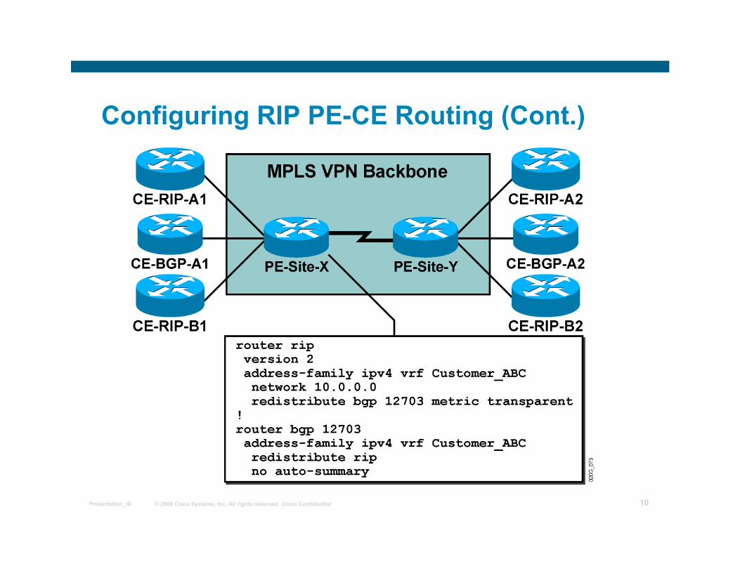
Configuring RIP PE-CE Routing (Cont.)
© 2008 Cisco Systems, Inc. All rights reserved. Cisco Confidential Presentation_ID 11
Loop Detection with RIP as PE-CE
RIP works with the following mechanisms for loop detection:
• Split Horizon • Site Of Origin (SOO)
© 2008 Cisco Systems, Inc. All rights reserved. Cisco Confidential Presentation_ID 12
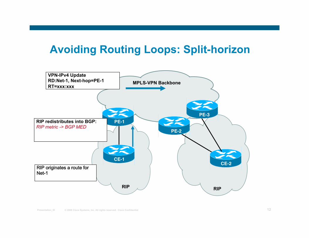
Avoiding Routing Loops: Split-horizon
MPLS-VPN Backbone
RIP
PE-1
CE-1
VPN-IPv4 Update RD:Net-1, Next-hop=PE-1 RT=xxx:xxx
RIP redistributes into BGP: RIP metric -> BGP MED
RIPoriginatesarouteforNet-1
RIP
PE-2
CE-2
PE-3
© 2008 Cisco Systems, Inc. All rights reserved. Cisco Confidential Presentation_ID 13
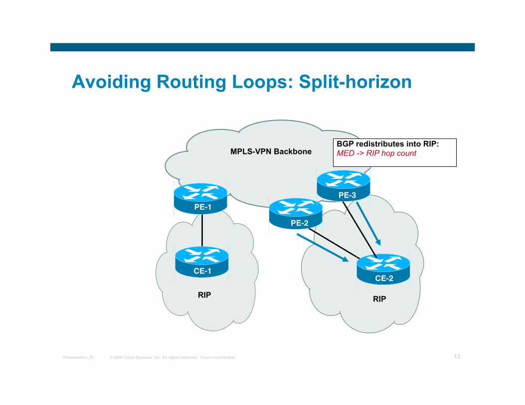
Avoiding Routing Loops: Split-horizon
MPLS-VPN Backbone
RIP
PE-1
CE-1 RIP
PE-2
CE-2
PE-3
BGP redistributes into RIP: MED -> RIP hop count
© 2008 Cisco Systems, Inc. All rights reserved. Cisco Confidential Presentation_ID 14
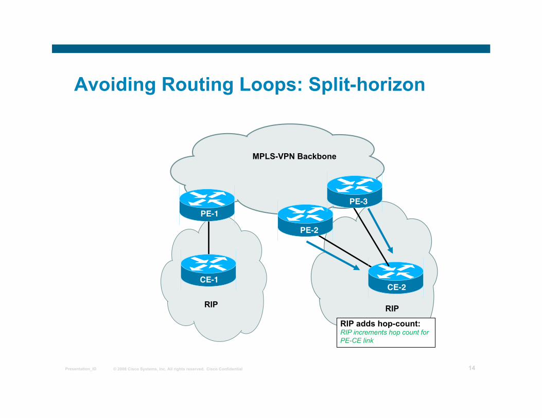
Avoiding Routing Loops: Split-horizon
MPLS-VPN Backbone
RIP
PE-1
CE-1 RIP
PE-2
CE-2
PE-3
RIP adds hop-count: RIP increments hop count for PE-CE link
© 2008 Cisco Systems, Inc. All rights reserved. Cisco Confidential Presentation_ID 15
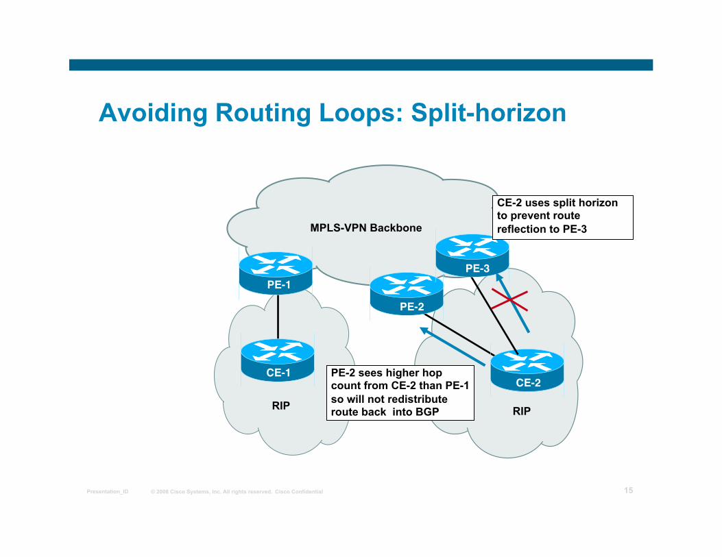
Avoiding Routing Loops: Split-horizon
MPLS-VPN Backbone
RIP
PE-1
RIP
PE-2
CE-2
PE-3
CE-2 uses split horizon to prevent route reflection to PE-3
PE-2 sees higher hop count from CE-2 than PE-1 so will not redistribute route back into BGP
CE-1
© 2008 Cisco Systems, Inc. All rights reserved. Cisco Confidential Presentation_ID 16
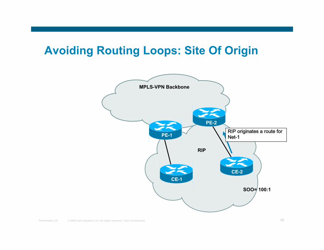
Avoiding Routing Loops: Site Of Origin
MPLS-VPN Backbone
RIPoriginatesarouteforNet-1
RIP
SOO= 100:1
PE-1
CE-1
PE-2
CE-2
© 2008 Cisco Systems, Inc. All rights reserved. Cisco Confidential Presentation_ID 17
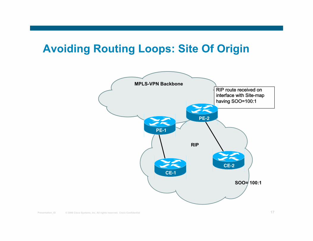
Avoiding Routing Loops: Site Of Origin
MPLS-VPN Backbone RIProutereceivedoninterfacewithSite-maphavingSOO=100:1
RIP
SOO= 100:1
PE-1
CE-1
PE-2
CE-2
© 2008 Cisco Systems, Inc. All rights reserved. Cisco Confidential Presentation_ID 18
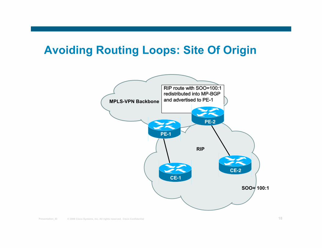
Avoiding Routing Loops: Site Of Origin
MPLS-VPN Backbone
RIProutewithSOO=100:1redistributedintoMP-BGPandadvertisedtoPE-1
RIP
SOO= 100:1
PE-1
CE-1
PE-2
CE-2
© 2008 Cisco Systems, Inc. All rights reserved. Cisco Confidential Presentation_ID 19
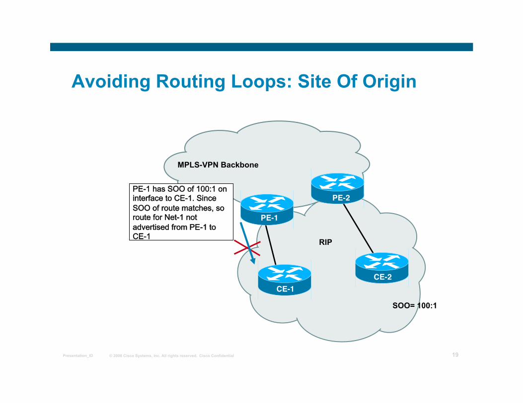
Avoiding Routing Loops: Site Of Origin
MPLS-VPN Backbone
PE-1hasSOOof100:1oninterfacetoCE-1.SinceSOOofroutematches,sorouteforNet-1notadvertisedfromPE-1toCE-1
RIP
SOO= 100:1
PE-1
CE-1
PE-2
CE-2
© 2008 Cisco Systems, Inc. All rights reserved. Cisco Confidential Presentation_ID 20
Summary RIP can be used as a PE-CE routing protocol
RIP v2 should be used as it supports VLSM
RIP has loop detection mechanisms to prevent routing loops with complex connectivity models
© 2008 Cisco Systems, Inc. All rights reserved. Cisco Confidential Presentation_ID 21
MPLS VPN Implementation
Troubleshooting MPLS VPN
© 2008 Cisco Systems, Inc. All rights reserved. Cisco Confidential Presentation_ID 22
Outline Overview MPLS VPN Troubleshooting Preliminary steps
Verify the Routing Information Flow Validating CE to PE Routing Information Flow Validating PE to PE Routing Information Flow Validating PE to CE Routing Information Flow Verifying the Data Flow Validating CEF Status Validating the End-to-end Label Switched Path
Validating the LIB status Lesson Summary
© 2008 Cisco Systems, Inc. All rights reserved. Cisco Confidential Presentation_ID 23
Preliminary steps in MPLS VPN Troubleshooting
Perform basic MPLS troubleshooting:
Is CEF enabled?
Are labels for IGP routes generated and propagated?
Are large labeled packets propagated across the MPLS backbone (maximum transmission unit issues)?
© 2008 Cisco Systems, Inc. All rights reserved. Cisco Confidential Presentation_ID 24
Verifying the Routing Information Flow
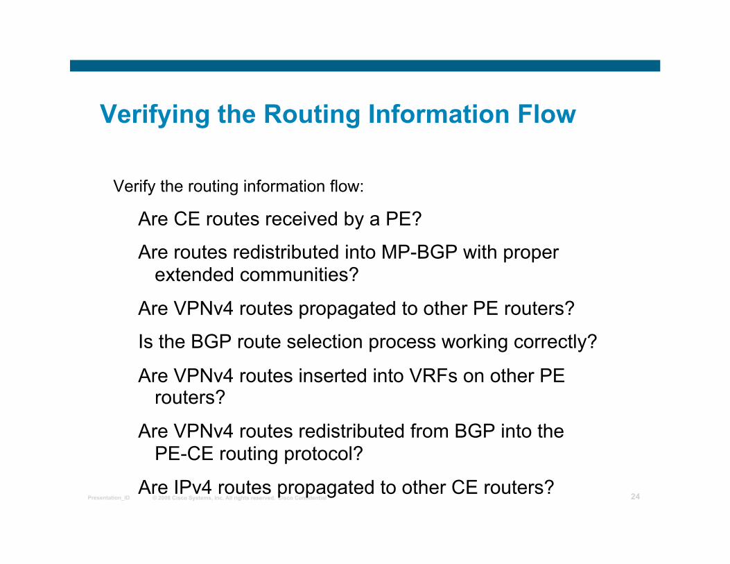
Verify the routing information flow:
Are CE routes received by a PE?
Are routes redistributed into MP-BGP with proper extended communities?
Are VPNv4 routes propagated to other PE routers?
Is the BGP route selection process working correctly?
Are VPNv4 routes inserted into VRFs on other PE routers?
Are VPNv4 routes redistributed from BGP into the PE-CE routing protocol?
Are IPv4 routes propagated to other CE routers?
© 2008 Cisco Systems, Inc. All rights reserved. Cisco Confidential Presentation_ID 25
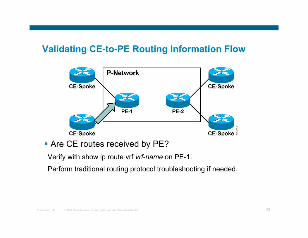
Validating CE-to-PE Routing Information Flow
Are CE routes received by PE? Verify with show ip route vrf vrf-name on PE-1.
Perform traditional routing protocol troubleshooting if needed.
© 2008 Cisco Systems, Inc. All rights reserved. Cisco Confidential Presentation_ID 26
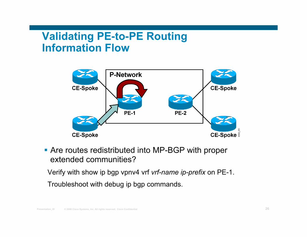
Validating PE-to-PE Routing Information Flow
Are routes redistributed into MP-BGP with proper extended communities?
Verify with show ip bgp vpnv4 vrf vrf-name ip-prefix on PE-1.
Troubleshoot with debug ip bgp commands.
© 2008 Cisco Systems, Inc. All rights reserved. Cisco Confidential Presentation_ID 27
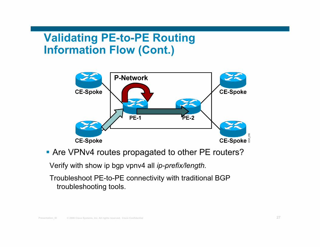
Validating PE-to-PE Routing Information Flow (Cont.)
Are VPNv4 routes propagated to other PE routers? Verify with show ip bgp vpnv4 all ip-prefix/length.
Troubleshoot PE-to-PE connectivity with traditional BGP troubleshooting tools.
© 2008 Cisco Systems, Inc. All rights reserved. Cisco Confidential Presentation_ID 28
Validating PE-to-PE Routing Information Flow (Cont.)
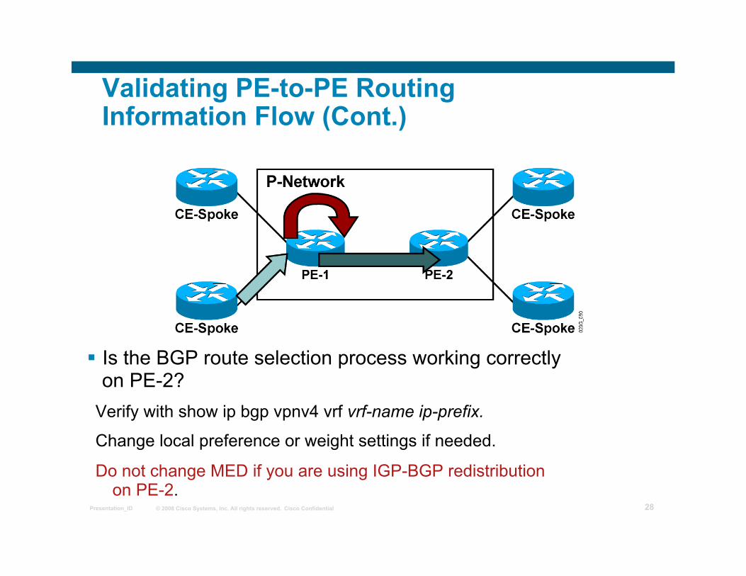
Is the BGP route selection process working correctly on PE-2?
Verify with show ip bgp vpnv4 vrf vrf-name ip-prefix.
Change local preference or weight settings if needed.
Do not change MED if you are using IGP-BGP redistribution on PE-2.
© 2008 Cisco Systems, Inc. All rights reserved. Cisco Confidential Presentation_ID 29
Validating PE-to-PE Routing Information Flow (Cont.)
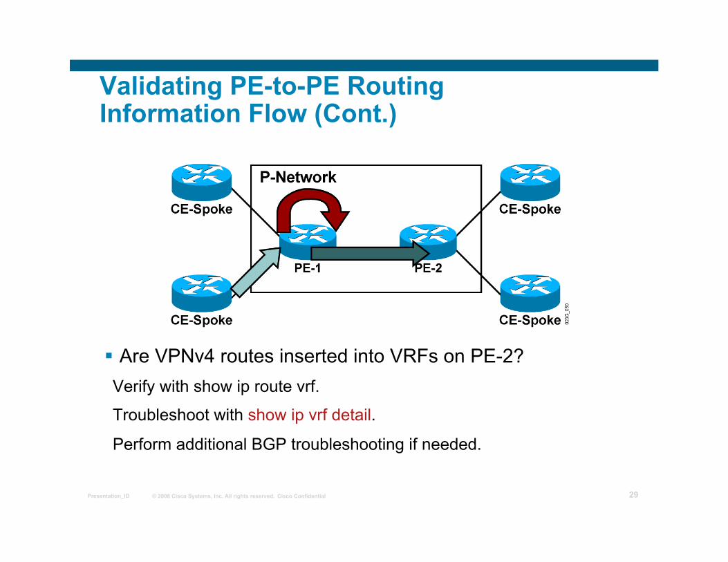
Are VPNv4 routes inserted into VRFs on PE-2? Verify with show ip route vrf.
Troubleshoot with show ip vrf detail.
Perform additional BGP troubleshooting if needed.
© 2008 Cisco Systems, Inc. All rights reserved. Cisco Confidential Presentation_ID 30
Validating PE-to-PE Routing Information Flow (Cont.)
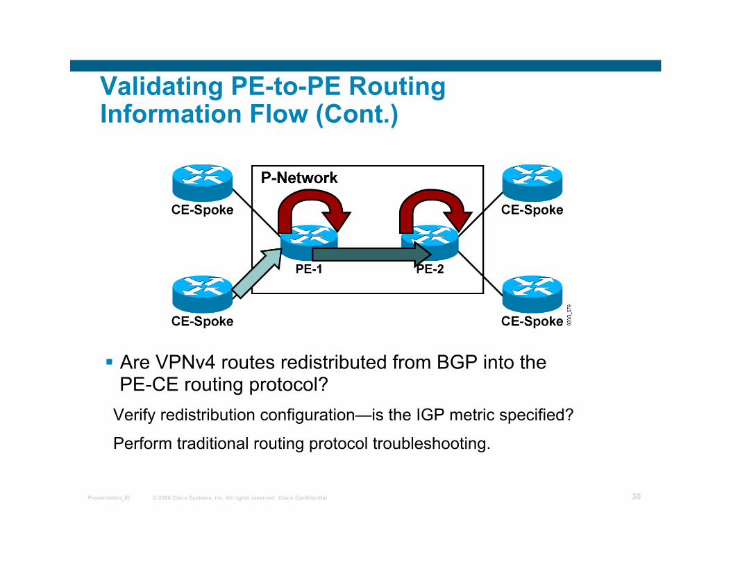
Are VPNv4 routes redistributed from BGP into the PE-CE routing protocol?
Verify redistribution configuration—is the IGP metric specified?
Perform traditional routing protocol troubleshooting.
© 2008 Cisco Systems, Inc. All rights reserved. Cisco Confidential Presentation_ID 31
Validating PE-to-CE Routing Information Flow
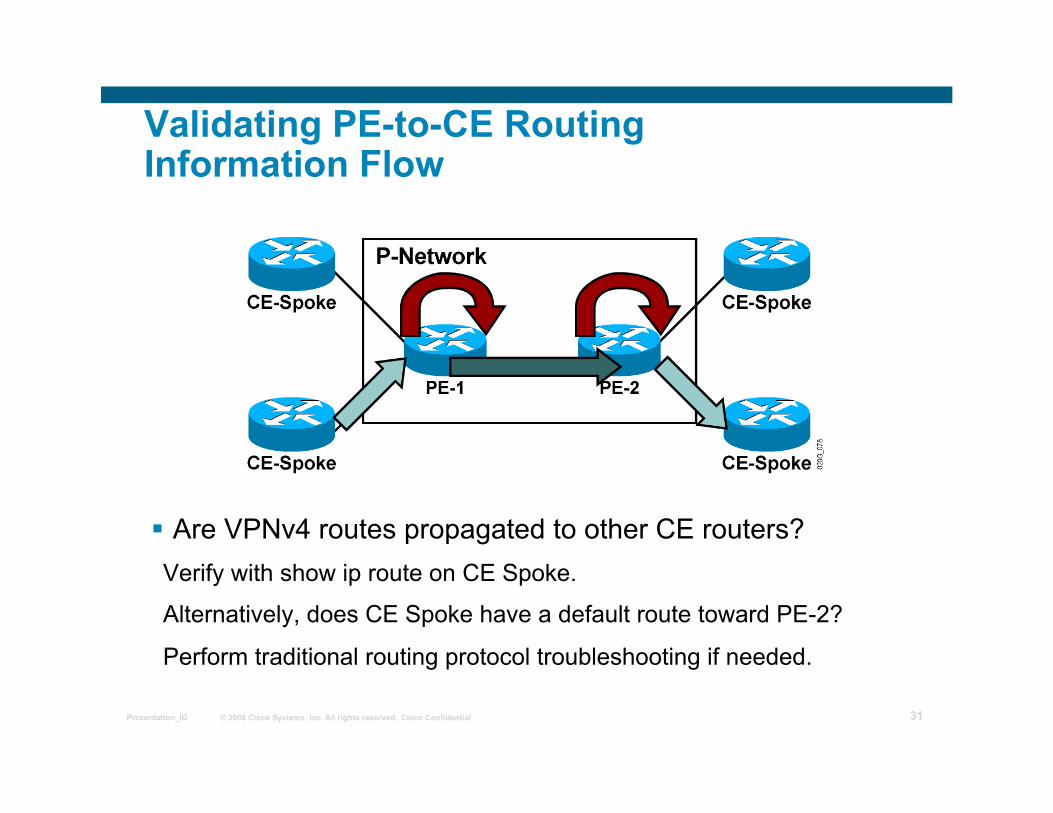
Are VPNv4 routes propagated to other CE routers? Verify with show ip route on CE Spoke.
Alternatively, does CE Spoke have a default route toward PE-2?
Perform traditional routing protocol troubleshooting if needed.
© 2008 Cisco Systems, Inc. All rights reserved. Cisco Confidential Presentation_ID 32
Verifying the Data Flow
Verify proper data flow:
Is CEF enabled on the ingress PE router interface?
Is the CEF entry correct on the ingress PE router?
Is there an end-to-end label switched path tunnel (LSP tunnel) between PE routers?
Is the LFIB entry on the egress PE router correct?
© 2008 Cisco Systems, Inc. All rights reserved. Cisco Confidential Presentation_ID 33
Validating CEF Status
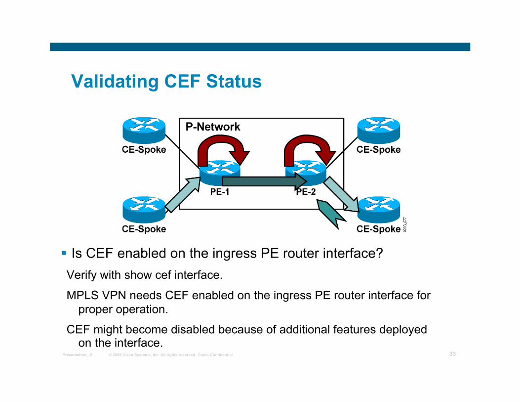
Is CEF enabled on the ingress PE router interface? Verify with show cef interface.
MPLS VPN needs CEF enabled on the ingress PE router interface for proper operation.
CEF might become disabled because of additional features deployed on the interface.
© 2008 Cisco Systems, Inc. All rights reserved. Cisco Confidential Presentation_ID 34
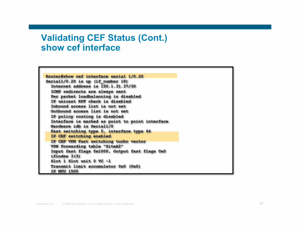
Validating CEF Status (Cont.) show cef interface
© 2008 Cisco Systems, Inc. All rights reserved. Cisco Confidential Presentation_ID 35
Validating CEF Status (Cont.)
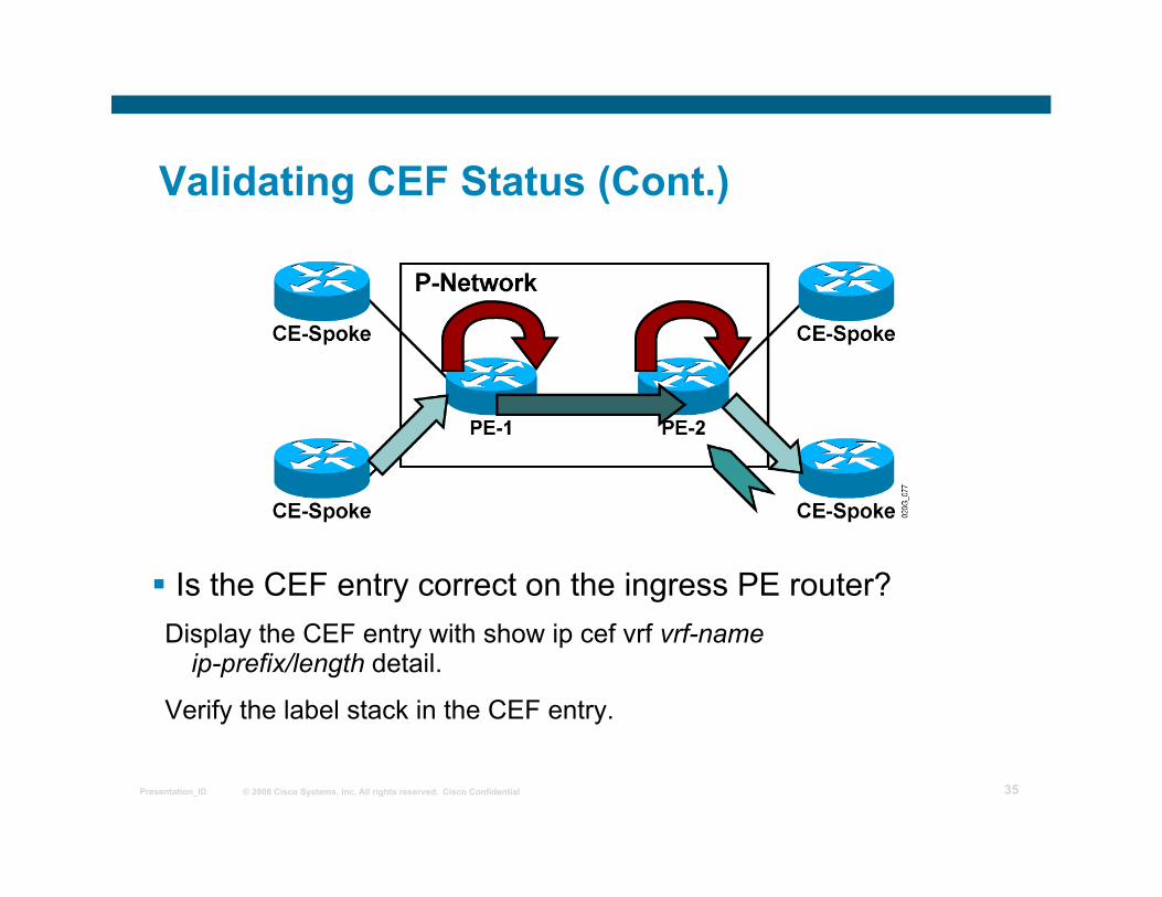
Is the CEF entry correct on the ingress PE router? Display the CEF entry with show ip cef vrf vrf-name
ip-prefix/length detail.
Verify the label stack in the CEF entry.
© 2008 Cisco Systems, Inc. All rights reserved. Cisco Confidential Presentation_ID 36
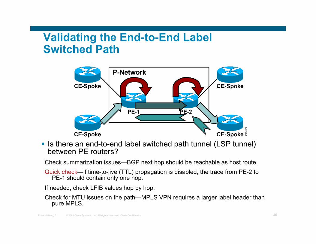
Validating the End-to-End Label Switched Path
Is there an end-to-end label switched path tunnel (LSP tunnel) between PE routers?
Check summarization issues—BGP next hop should be reachable as host route. Quick check—if time-to-live (TTL) propagation is disabled, the trace from PE-2 to
PE-1 should contain only one hop.
If needed, check LFIB values hop by hop. Check for MTU issues on the path—MPLS VPN requires a larger label header than
pure MPLS.
© 2008 Cisco Systems, Inc. All rights reserved. Cisco Confidential Presentation_ID 37
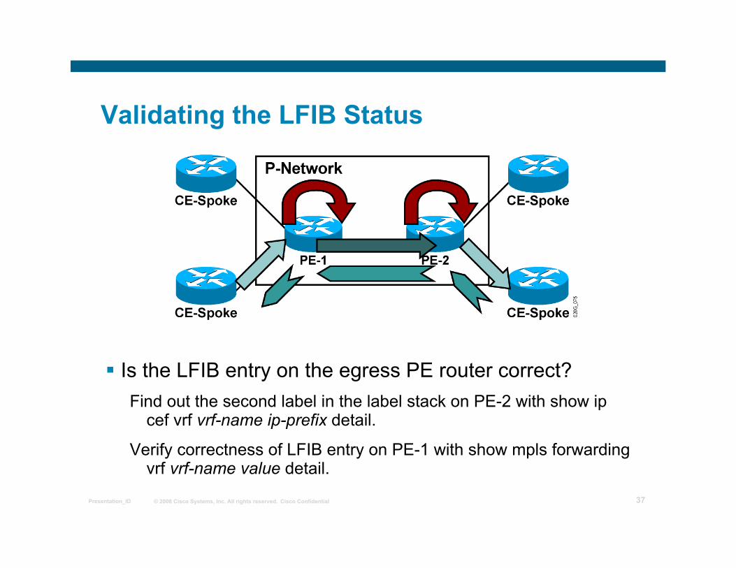
Validating the LFIB Status
Is the LFIB entry on the egress PE router correct? Find out the second label in the label stack on PE-2 with show ip
cef vrf vrf-name ip-prefix detail.
Verify correctness of LFIB entry on PE-1 with show mpls forwarding vrf vrf-name value detail.
© 2008 Cisco Systems, Inc. All rights reserved. Cisco Confidential Presentation_ID 38
Summary
MPLS troubleshooting can be divided into two main steps: Verify routing information flow
Verify proper data flow
Routing information flow troubleshooting requires verification of end-to-end routing information propagation between CE routers.
Verification of the routing information flow should be done systematically, starting at the routing ingress CE and moving to the egress CE.
Verification of the data flow should be done systematically, starting at the data flow ingress CE and moving to the egress CE.

© 2008 Cisco Systems, Inc. All rights reserved. Cisco Confidential Presentation_ID 39
Multi-VRF CE (aka VRF-lite)
MPLS workshop
© 2008 Cisco Systems, Inc. All rights reserved. Cisco Confidential Presentation_ID 40
Agenda
What is Multi-VRF/VRF Lite?
Applications
Implementation Example
Limitations
OSPF “capability vrf-lite”
Conclusion
© 2008 Cisco Systems, Inc. All rights reserved. Cisco Confidential Presentation_ID 41
What is Multi-VRF CE? Multi-VRF CE architecture uses the VRF concept to
support multiple (overlapping and independent) routing tables (and forwarding tables) per customer
Not a feature but an application based on VRF implementation
Any routing protocol supported by normal VRF can be used in a Multi-VRF CE implementation
The CE supports traffic separation between customer networks
There is no MPLS functionality on the CE, no label exchange between the CE and PE
© 2008 Cisco Systems, Inc. All rights reserved. Cisco Confidential Presentation_ID 42
PE
CE
VPN-A
VPN-B
CE
CE
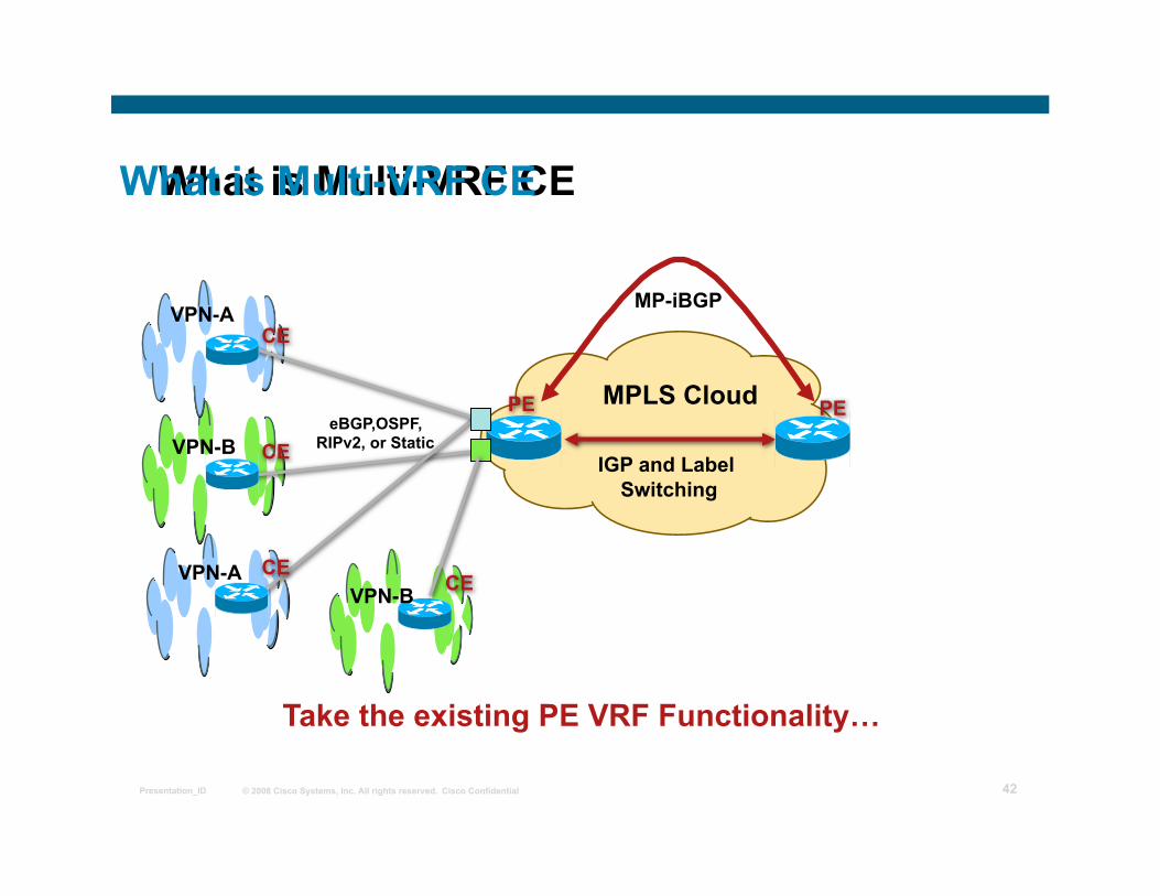
Take the existing PE VRF Functionality…
IGP and Label Switching
What is Multi-VRF CE
CE
MP-iBGP
PE
VPN-B VPN-A
MPLS Cloud eBGP,OSPF,
RIPv2, or Static
What is Multi-VRF CE
© 2008 Cisco Systems, Inc. All rights reserved. Cisco Confidential Presentation_ID 43
PE
CE
VPN-A
VPN-B
CE
CE
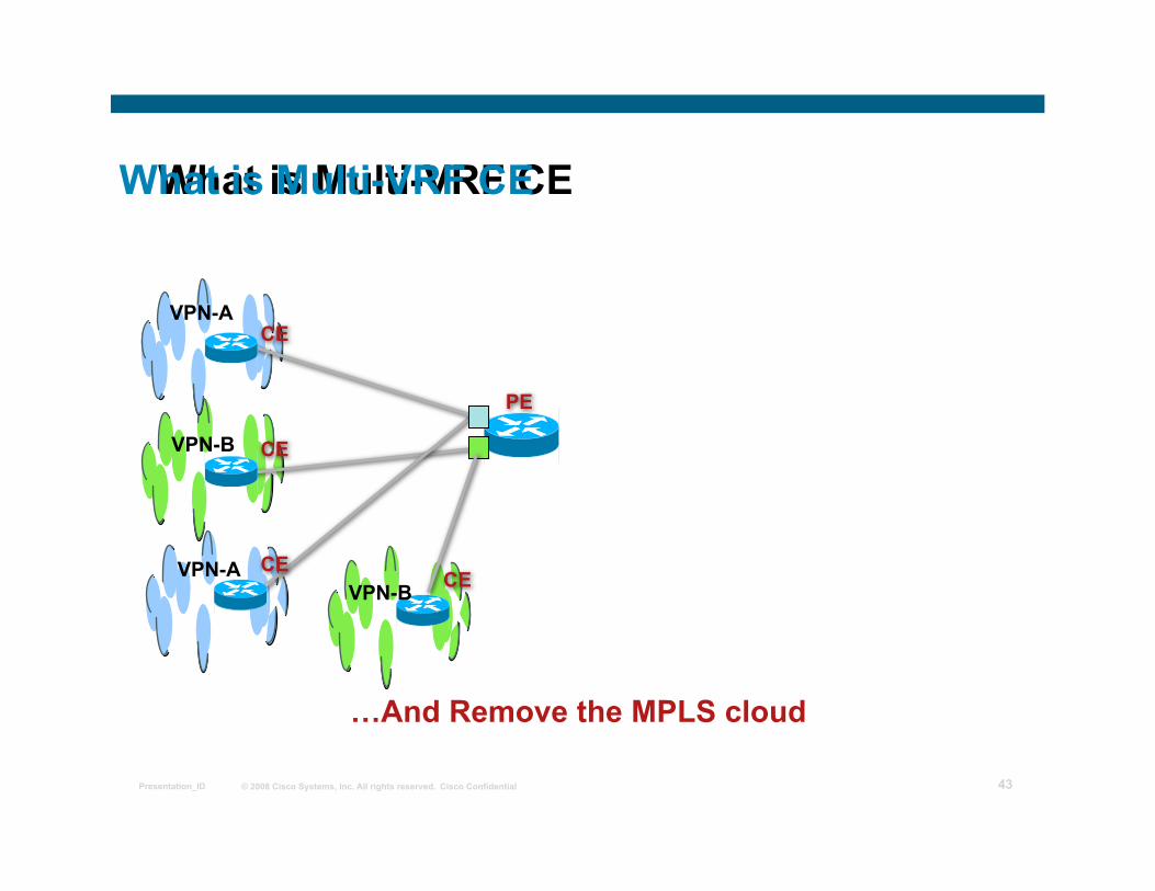
…And Remove the MPLS cloud
What is Multi-VRF CE
CE VPN-B VPN-A
What is Multi-VRF CE
© 2008 Cisco Systems, Inc. All rights reserved. Cisco Confidential Presentation_ID 44
Multi VRF CE CE
VPN-A
VPN-B
CE or PE CE
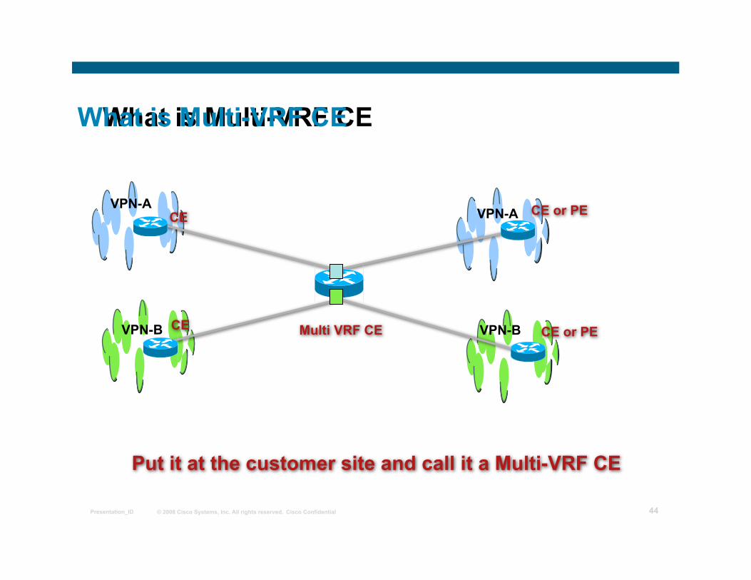
Put it at the customer site and call it a Multi-VRF CE
What is Multi-VRF CE
CE or PE VPN-B
VPN-A
What is Multi-VRF CE
© 2008 Cisco Systems, Inc. All rights reserved. Cisco Confidential Presentation_ID 45
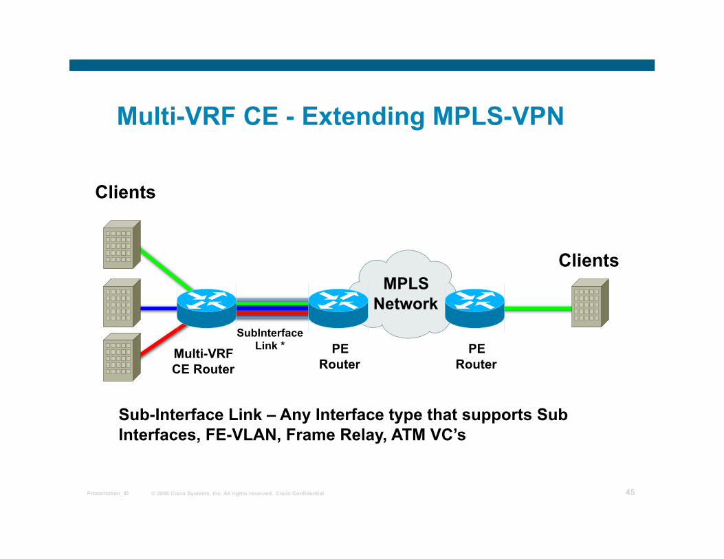
Multi-VRF CE - Extending MPLS-VPN
Clients
PE Router
MPLS Network
Multi-VRF CE Router
SubInterface Link *
Sub-Interface Link – Any Interface type that supports Sub Interfaces, FE-VLAN, Frame Relay, ATM VC’s
PE Router
Clients
© 2008 Cisco Systems, Inc. All rights reserved. Cisco Confidential Presentation_ID 46
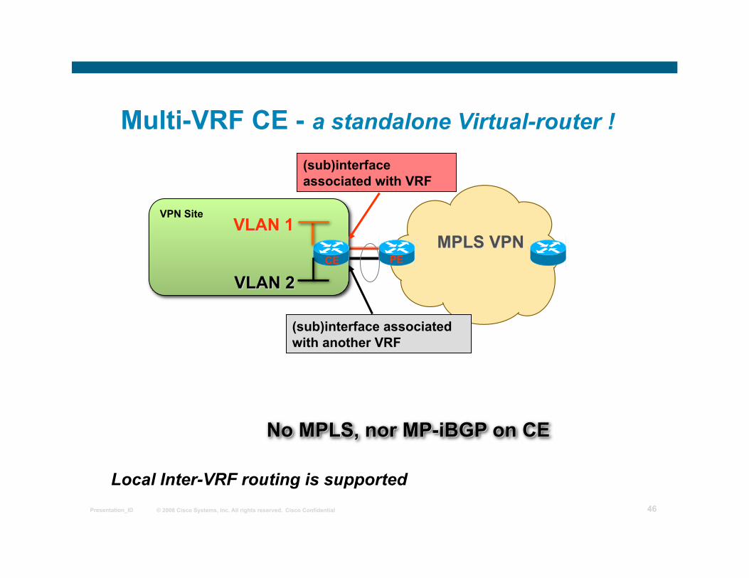
Multi-VRF CE - a standalone Virtual-router !
Local Inter-VRF routing is supported
PE
(sub)interface associated with VRF
CE
© 2008 Cisco Systems, Inc. All rights reserved. Cisco Confidential Presentation_ID 47
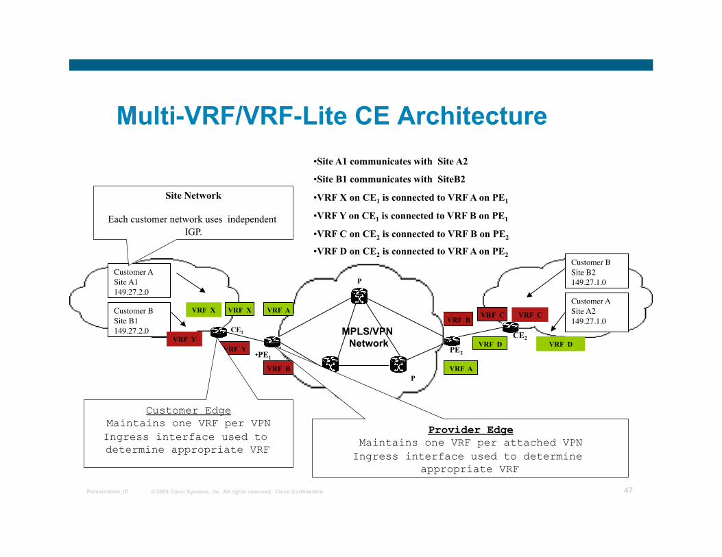
Multi-VRF/VRF-Lite CE Architecture
- -
CE1
CE
P
P P
VRF X
VRF B
VRF B
VRF A
Customer A Site A1 149.27.2.0
Customer B Site B1 149.27.2.0
Customer B Site B2 149.27.1.0
Customer A Site A2 149.27.1.0
VRF A
VRF Y VRF D
VRF C
Site Network
Each customer network uses independent IGP.
Customer Edge Maintains one VRF per VPN Ingress interface used to determine appropriate VRF
Provider Edge Maintains one VRF per attached VPN
Ingress interface used to determine appropriate VRF
MPLS/VPN Network
VRF X
VRF Y
VRF C
VRF D
• Site A1 communicates with Site A2
• Site B1 communicates with SiteB2
• VRF X on CE1 is connected to VRF A on PE1
• VRF Y on CE1 is connected to VRF B on PE1
• VRF C on CE2 is connected to VRF B on PE2
• VRF D on CE2 is connected to VRF A on PE2
• PE1
CE2
PE2
© 2008 Cisco Systems, Inc. All rights reserved. Cisco Confidential Presentation_ID 48
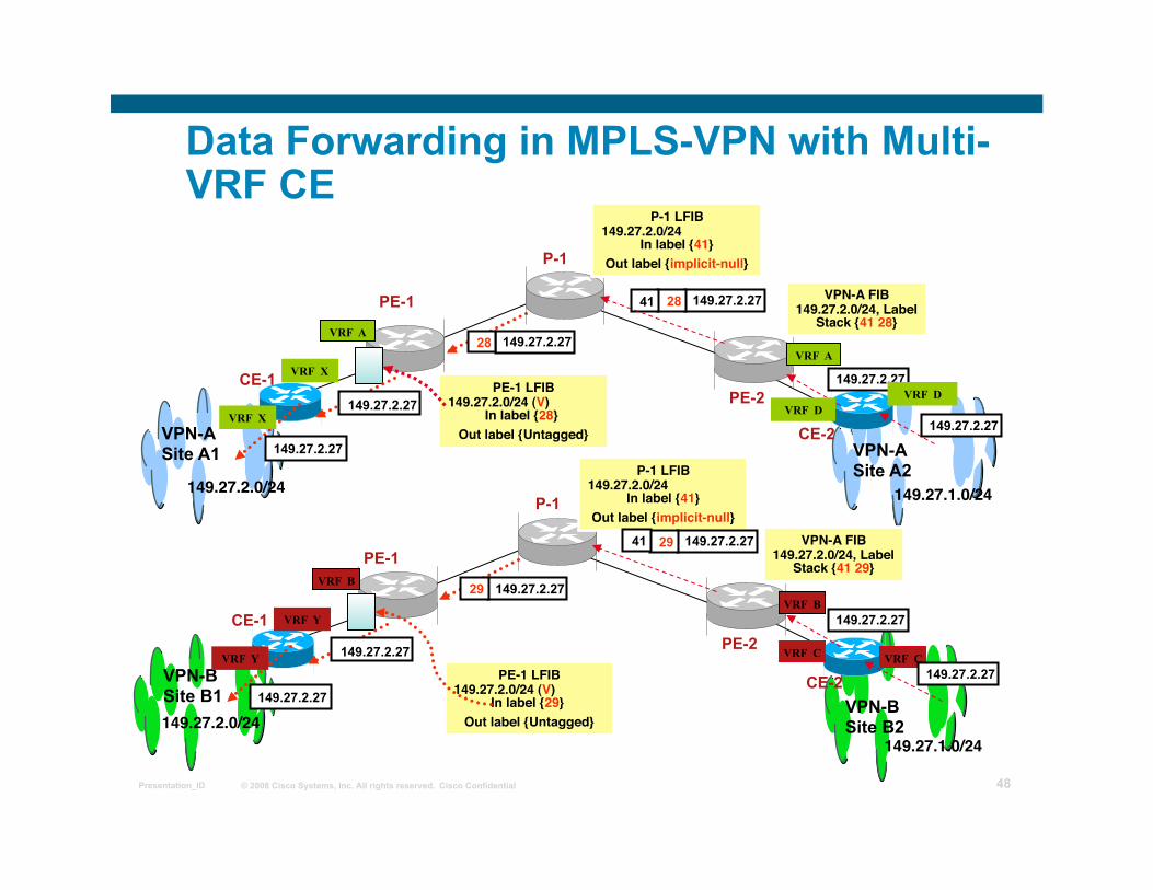
VPN-A Site A1 VPN-A
Site A2 149.27.2.0/24
CE-1
PE-1
PE-2
CE-2
VPN-A FIB149.27.2.0/24, Label
Stack {41 28}
P-1
P-1 LFIB149.27.2.0/24
In label {41} Out label {implicit-null}
149.27.2.27 28
PE-1 LFIB149.27.2.0/24 (V)
In label {28} Out label {Untagged}
149.27.2.27
149.27.1.0/24
VPN-B Site B1 VPN-B
Site B2 149.27.2.0/24
CE-1
PE-1
PE-2
CE-2
VPN-A FIB149.27.2.0/24, Label
Stack {41 29}
P-1
P-1 LFIB149.27.2.0/24
In label {41} Out label {implicit-null}
149.27.2.27 29
PE-1 LFIB149.27.2.0/24 (V)
In label {29} Out label {Untagged}
149.27.2.27
149.27.1.0/24
149.27.2.27
149.27.2.27 28 41
149.27.2.27
149.27.2.27 29 41
149.27.2.27
149.27.2.27
VRF Y
VRF Y
VRF X
VRF X
VRF D 149.27.2.27
VRF D
VRF C VRF C 149.27.2.27
VRF B
VRF A
VRF A
VRF B
Data Forwarding in MPLS-VPN with Multi-VRF CE
© 2008 Cisco Systems, Inc. All rights reserved. Cisco Confidential Presentation_ID 49
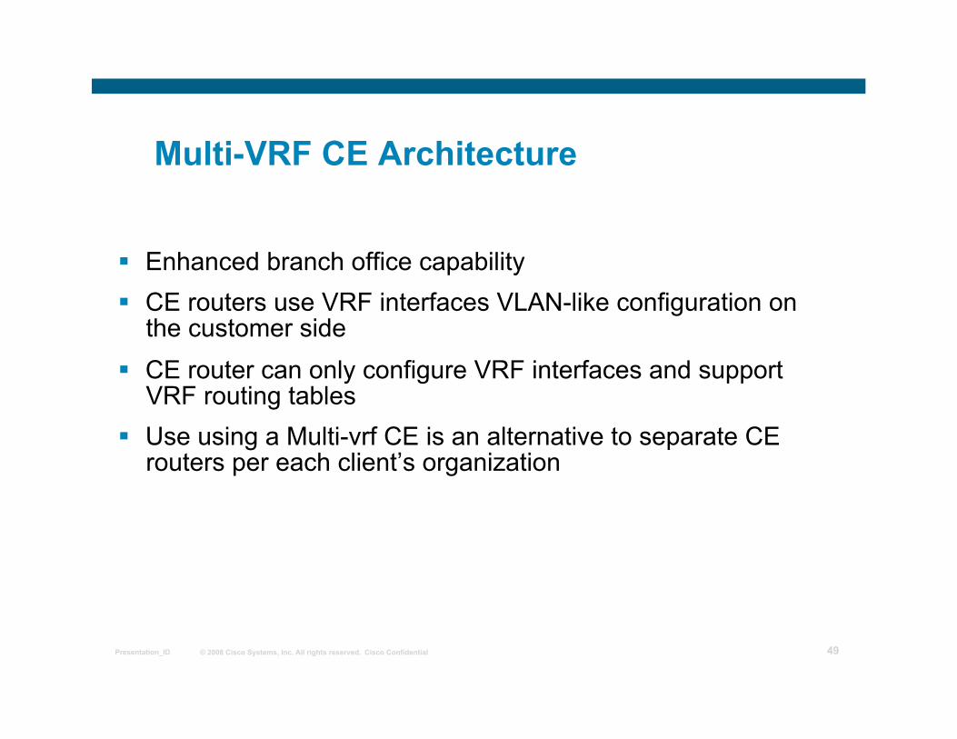
Multi-VRF CE Architecture
Enhanced branch office capability CE routers use VRF interfaces VLAN-like configuration on
the customer side CE router can only configure VRF interfaces and support
VRF routing tables Use using a Multi-vrf CE is an alternative to separate CE
routers per each client’s organization

© 2008 Cisco Systems, Inc. All rights reserved. Cisco Confidential Presentation_ID 50
Multi-VRF CE Architecture: Replaces Separate CE Routers
CE router
PE router MPLS network
Site 1
Engineering
HR
Finance
CE router
CE router
© 2008 Cisco Systems, Inc. All rights reserved. Cisco Confidential Presentation_ID 51
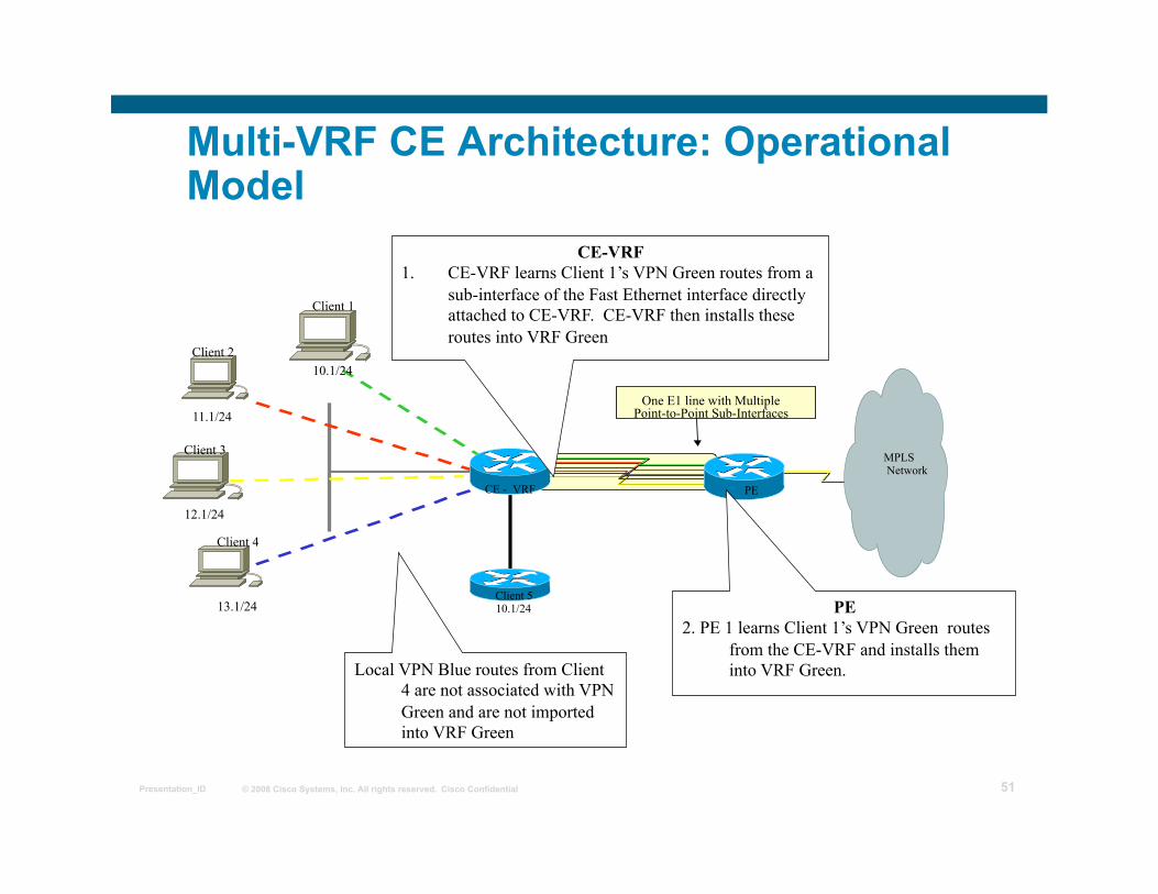
Multi-VRF CE Architecture: Operational Model
CE - VRF
Client 5 10.1/24
PE
Client 1
10.1/24 Client 2
11.1/24 MPLS Network
Client 3
12.1/24 Client 4
13.1/24
One E1 line with Multiple Point-to-Point Sub-Interfaces
CE-VRF 1. CE-VRF learns Client 1’s VPN Green routes from a
sub-interface of the Fast Ethernet interface directly attached to CE-VRF. CE-VRF then installs these routes into VRF Green
PE 2. PE 1 learns Client 1’s VPN Green routes
from the CE-VRF and installs them into VRF Green. Local VPN Blue routes from Client
4 are not associated with VPN Green and are not imported into VRF Green
© 2008 Cisco Systems, Inc. All rights reserved. Cisco Confidential Presentation_ID 52
Applications: Two Examples
Internet and VPN Service Using the Same CE – solution is attractive for small businesses that do not want to install separate CE routers for each service
Implement Multiple VPNs in a customer site using a single router
© 2008 Cisco Systems, Inc. All rights reserved. Cisco Confidential Presentation_ID 53
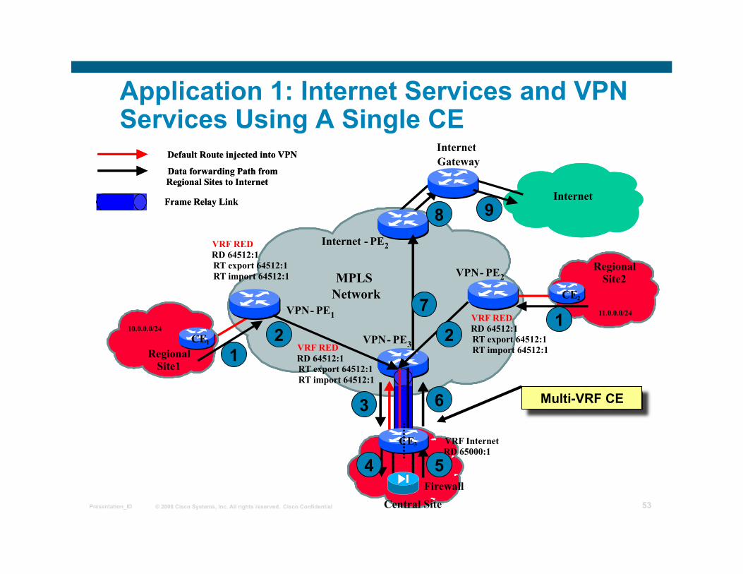
Application 1: Internet Services and VPN Services Using A Single CE
MPLS Network
VPN - PE 2
11.0.0.0/24 VPN - PE 3
VPN - PE 1 10.0.0.0/24
VRF RED RD 64512:1 RT export 64512:1 RT import 64512:1
VRF RED RD 64512:1 RT export 64512:1 RT import 64512:1
Central Site
Regional Site2
Regional Site1
VRF RED RD 64512:1 RT export 64512:1 RT import 64512:1
Internet
Internet - PE 2
Internet Gateway
Firewall
CE 3
CE 2
CE 1
VRF Internet RD 65000:1
Data forwarding Path from Regional Sites to Internet Data forwarding Path from Regional Sites to Internet Default Route injected into VPN Default Route injected into VPN
The image cannot be displayed. Your computer
Frame Relay Link The image cannot be displayed. Your computer
Frame Relay Link
Multi-VRF CE
1 2
3
4
7
6
5
8 9
1 2
© 2008 Cisco Systems, Inc. All rights reserved. Cisco Confidential Presentation_ID 54
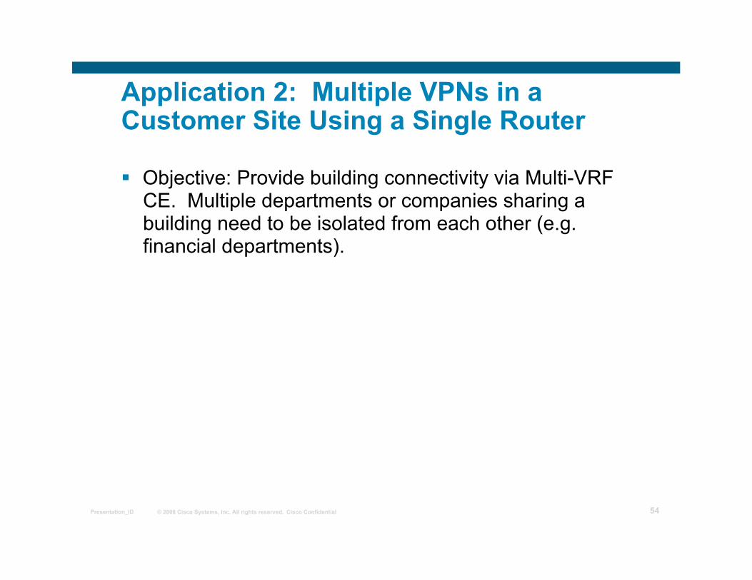
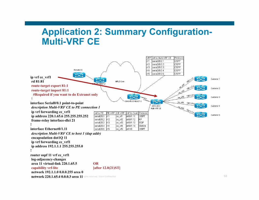
Application 2: Multiple VPNs in a Customer Site Using a Single Router
Objective: Provide building connectivity via Multi-VRF CE. Multiple departments or companies sharing a building need to be isolated from each other (e.g. financial departments).
© 2008 Cisco Systems, Inc. All rights reserved. Cisco Confidential Presentation_ID 55
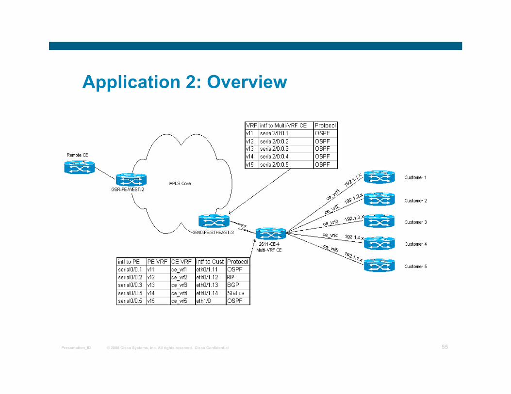
Application 2: Overview
© 2008 Cisco Systems, Inc. All rights reserved. Cisco Confidential Presentation_ID 56
Application 2: Basic Setup
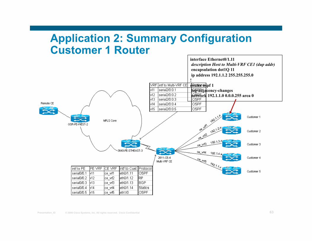
Inter-site connectivity policies All Customer Routers can communicate with Remote CE’s but not with each other.
All Traffic off 2611-CE-4 is segmented into 5 separate VRFs (labeled ce_vrf1-5)
3640-PE-STHEAST-3 uses OSPF as the routing protocol to exchange updates with 2611-CE4, but other routing protocols may be used as well
All other hosts off 2611-CE4 use a combination of OSPF, EBGP, RIPv2 and static routes
© 2008 Cisco Systems, Inc. All rights reserved. Cisco Confidential Presentation_ID 57
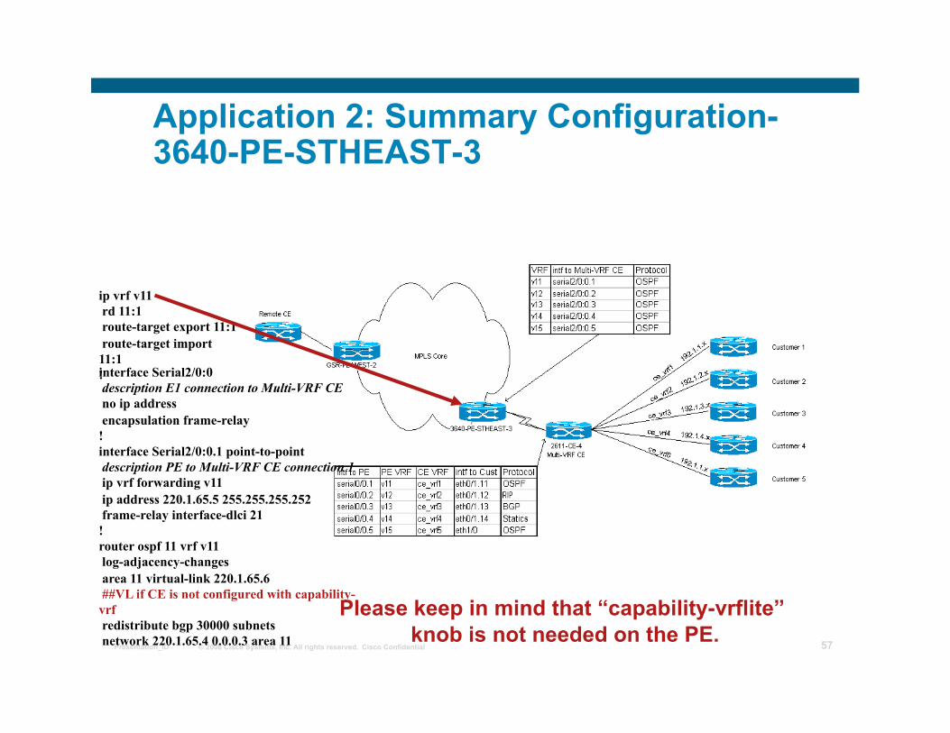
Application 2: Summary Configuration- 3640-PE-STHEAST-3
ip vrf v11 rd 11:1 route-target export 11:1 route-target import 11:1 ! interface Serial2/0:0 description E1 connection to Multi-VRF CE no ip address encapsulation frame-relay ! interface Serial2/0:0.1 point-to-point description PE to Multi-VRF CE connection 1 ip vrf forwarding v11 ip address 220.1.65.5 255.255.255.252 frame-relay interface-dlci 21 ! router ospf 11 vrf v11 log-adjacency-changes area 11 virtual-link 220.1.65.6 ##VL if CE is not configured with capability-vrf redistribute bgp 30000 subnets network 220.1.65.4 0.0.0.3 area 11
Please keep in mind that “capability-vrflite” knob is not needed on the PE.
© 2008 Cisco Systems, Inc. All rights reserved. Cisco Confidential Presentation_ID 58
Application 2: Summary Configuration- Multi-VRF CE
ip vrf ce_vrf1 rd 81:81 route-target export 81:1 route-target import 81:1 #Required if you want to do Extranet only ! interface Serial0/0.1 point-to-point description Multi-VRF CE to PE connection 1 ip vrf forwarding ce_vrf1 ip address 220.1.65.6 255.255.255.252 frame-relay interface-dlci 21 ! interface Ethernet0/1.11 description Multi-VRF CE to host 1 (dup addr) encapsulation dot1Q 11 ip vrf forwarding ce_vrf1 ip address 192.1.1.1 255.255.255.0 ! router ospf 11 vrf ce_vrf1 log-adjacency-changes area 11 virtual-link 220.1.65.5 OR capability vrf-lite [after 12.0(21)ST] network 192.1.1.0 0.0.0.255 area 0 network 220.1.65.4 0.0.0.3 area 11
© 2008 Cisco Systems, Inc. All rights reserved. Cisco Confidential Presentation_ID 59
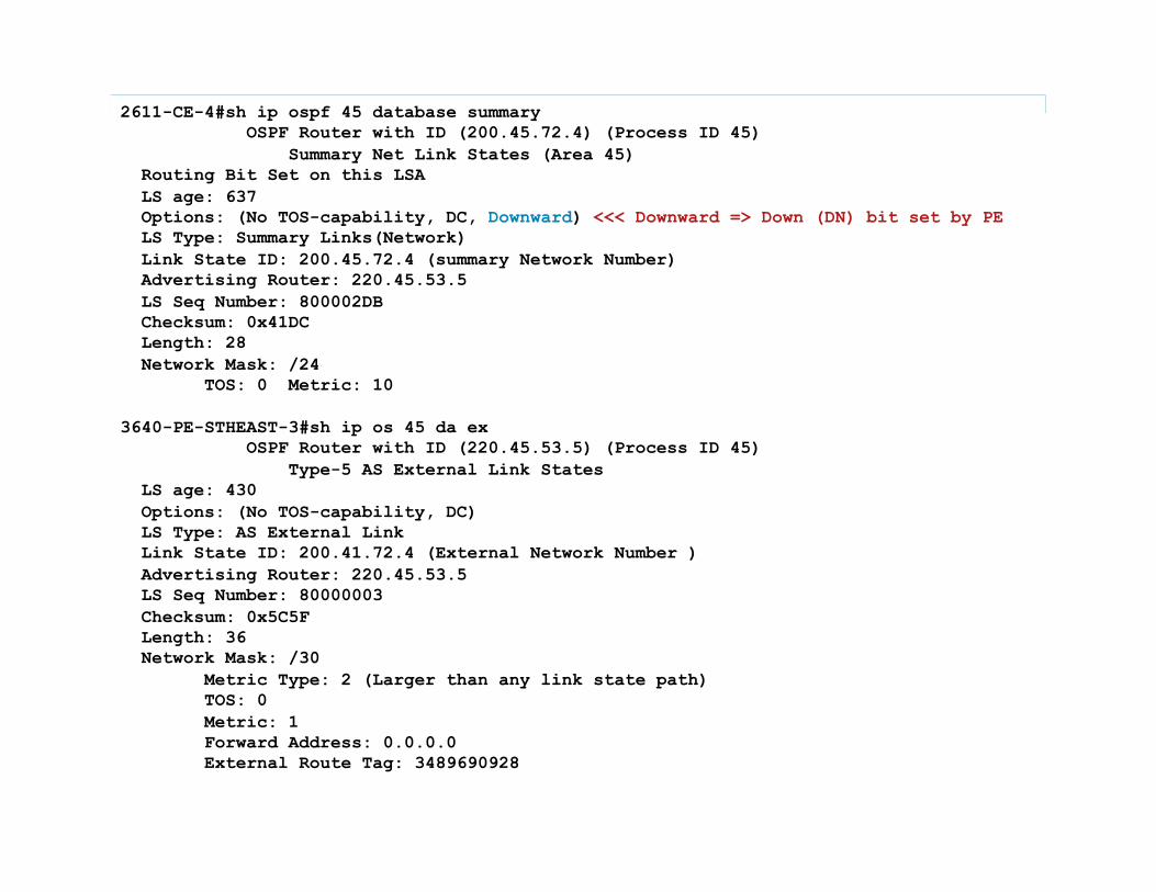
OSPF “Capability vrf-lite” To suppress PE-specific checks on a CE-vrf-lite
router (OSPF ‘DOWN’ Bit used only in VPNs) These checks are required to prevent loops when PE
is performing mutual redistribution between OSPF and BGP
Reference: CSCds82178 For the Multi-VRF CE these checks may be turned
off: router ospf 100 vrf ce_vrf1
capability vrf-lite
© 2008 Cisco Systems, Inc. All rights reserved. Cisco Confidential Presentation_ID 60
OSPF “Capability vrf-lite”
When the OSPF process is associated with the VRF, several checks are performed when LSAs are received:
If Type-3 LSA is received, DN bit is checked. If DN bit is set, Type-3 LSA is not considered during the SPF If Type-5/7 LSA is received and the Tag in the LSA is equal to the VPN-tag, Type-5/7 LSA is not considered during the SPF
These checks are needed to prevent loops when PE is performing a mutual redistribution between OSPF and BGP.
© 2008 Cisco Systems, Inc. All rights reserved. Cisco Confidential Presentation_ID 61
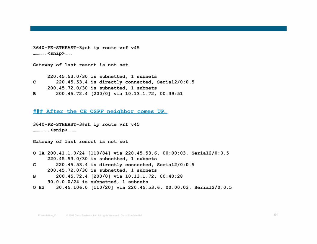
3640-PE-STHEAST-3#sh ip route vrf v45 ………..<snip>…….
Gateway of last resort is not set
220.45.53.0/30 is subnetted, 1 subnets C 220.45.53.4 is directly connected, Serial2/0:0.5 200.45.72.0/30 is subnetted, 1 subnets B 200.45.72.4 [200/0] via 10.13.1.72, 00:39:51
### After the CE OSPF neighbor comes UP…
3640-PE-STHEAST-3#sh ip route vrf v45 …………..<snip>………
Gateway of last resort is not set
O IA 200.41.1.0/24 [110/84] via 220.45.53.6, 00:00:03, Serial2/0:0.5 220.45.53.0/30 is subnetted, 1 subnets C 220.45.53.4 is directly connected, Serial2/0:0.5 200.45.72.0/30 is subnetted, 1 subnets B 200.45.72.4 [200/0] via 10.13.1.72, 00:40:28 30.0.0.0/24 is subnetted, 1 subnets O E2 30.45.106.0 [110/20] via 220.45.53.6, 00:00:03, Serial2/0:0.5
© 2008 Cisco Systems, Inc. All rights reserved. Cisco Confidential Presentation_ID 62
2611-CE-4#sh ip ospf 45 database summary OSPF Router with ID (200.45.72.4) (Process ID 45) Summary Net Link States (Area 45) Routing Bit Set on this LSA LS age: 637 Options: (No TOS-capability, DC, Downward) <<< Downward => Down (DN) bit set by PE LS Type: Summary Links(Network) Link State ID: 200.45.72.4 (summary Network Number) Advertising Router: 220.45.53.5 LS Seq Number: 800002DB Checksum: 0x41DC Length: 28 Network Mask: /24 TOS: 0 Metric: 10
3640-PE-STHEAST-3#sh ip os 45 da ex OSPF Router with ID (220.45.53.5) (Process ID 45) Type-5 AS External Link States LS age: 430 Options: (No TOS-capability, DC) LS Type: AS External Link Link State ID: 200.41.72.4 (External Network Number ) Advertising Router: 220.45.53.5 LS Seq Number: 80000003 Checksum: 0x5C5F Length: 36 Network Mask: /30 Metric Type: 2 (Larger than any link state path) TOS: 0 Metric: 1 Forward Address: 0.0.0.0 External Route Tag: 3489690928
© 2008 Cisco Systems, Inc. All rights reserved. Cisco Confidential Presentation_ID 63
Application 2: Summary Configuration Customer 1 Router
interface Ethernet0/1.11 description Host to Multi-VRF CE1 (dup addr) encapsulation dot1Q 11 ip address 192.1.1.2 255.255.255.0 ! router ospf 1 log-adjacency-changes network 192.1.1.0 0.0.0.255 area 0
© 2008 Cisco Systems, Inc. All rights reserved. Cisco Confidential Presentation_ID 64
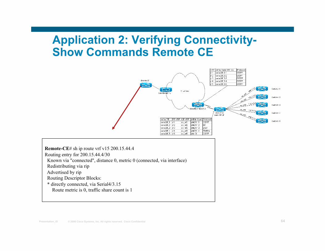
Application 2: Verifying Connectivity- Show Commands Remote CE
Remote-CE# sh ip route vrf v15 200.15.44.4 Routing entry for 200.15.44.4/30 Known via "connected", distance 0, metric 0 (connected, via interface) Redistributing via rip Advertised by rip Routing Descriptor Blocks: * directly connected, via Serial4/3.15 Route metric is 0, traffic share count is 1
© 2008 Cisco Systems, Inc. All rights reserved. Cisco Confidential Presentation_ID 65
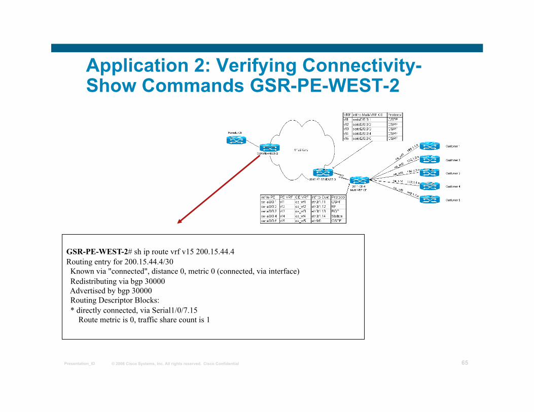
Application 2: Verifying Connectivity- Show Commands GSR-PE-WEST-2
GSR-PE-WEST-2# sh ip route vrf v15 200.15.44.4 Routing entry for 200.15.44.4/30 Known via "connected", distance 0, metric 0 (connected, via interface) Redistributing via bgp 30000 Advertised by bgp 30000 Routing Descriptor Blocks: * directly connected, via Serial1/0/7.15 Route metric is 0, traffic share count is 1
© 2008 Cisco Systems, Inc. All rights reserved. Cisco Confidential Presentation_ID 66
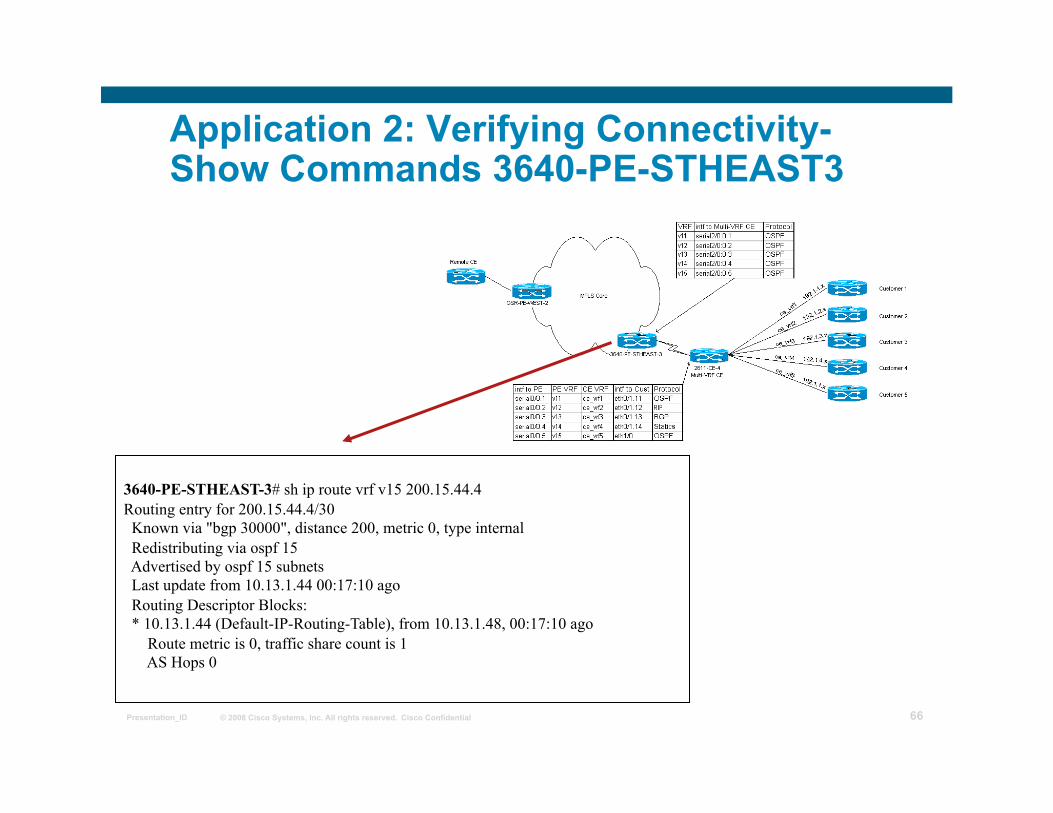
Application 2: Verifying Connectivity- Show Commands 3640-PE-STHEAST3
3640-PE-STHEAST-3# sh ip route vrf v15 200.15.44.4 Routing entry for 200.15.44.4/30 Known via "bgp 30000", distance 200, metric 0, type internal Redistributing via ospf 15 Advertised by ospf 15 subnets Last update from 10.13.1.44 00:17:10 ago Routing Descriptor Blocks: * 10.13.1.44 (Default-IP-Routing-Table), from 10.13.1.48, 00:17:10 ago Route metric is 0, traffic share count is 1 AS Hops 0
© 2008 Cisco Systems, Inc. All rights reserved. Cisco Confidential Presentation_ID 67
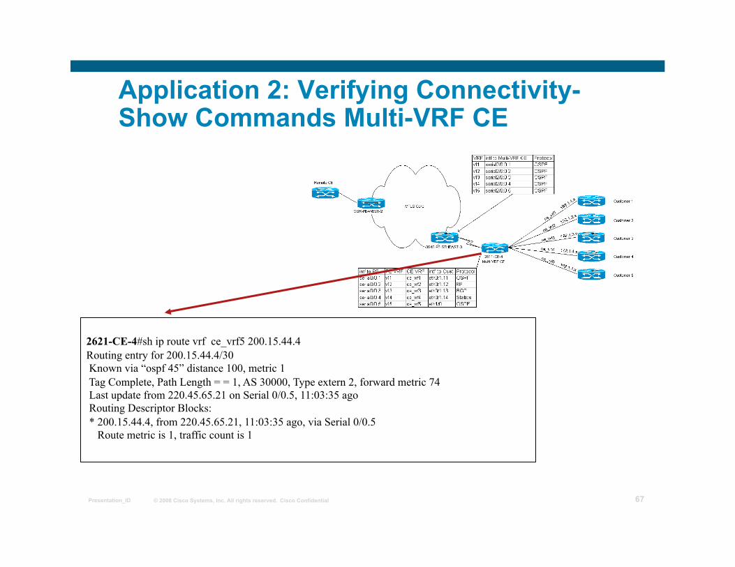
Application 2: Verifying Connectivity- Show Commands Multi-VRF CE
2621-CE-4#sh ip route vrf ce_vrf5 200.15.44.4 Routing entry for 200.15.44.4/30 Known via “ospf 45” distance 100, metric 1 Tag Complete, Path Length = = 1, AS 30000, Type extern 2, forward metric 74 Last update from 220.45.65.21 on Serial 0/0.5, 11:03:35 ago Routing Descriptor Blocks: * 200.15.44.4, from 220.45.65.21, 11:03:35 ago, via Serial 0/0.5 Route metric is 1, traffic count is 1
© 2008 Cisco Systems, Inc. All rights reserved. Cisco Confidential Presentation_ID 68
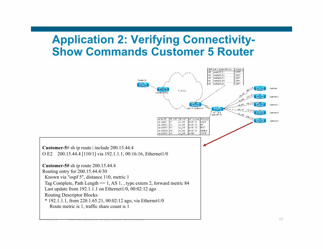
Application 2: Verifying Connectivity- Show Commands Customer 5 Router
Customer-5# sh ip route | include 200.15.44.4 O E2 200.15.44.4 [110/1] via 192.1.1.1, 00:16:16, Ethernet1/0
Customer-5# sh ip route 200.15.44.4 Routing entry for 200.15.44.4/30 Known via "ospf 5", distance 110, metric 1 Tag Complete, Path Length == 1, AS 1, , type extern 2, forward metric 84 Last update from 192.1.1.1 on Ethernet1/0, 00:02:12 ago Routing Descriptor Blocks: * 192.1.1.1, from 220.1.65.21, 00:02:12 ago, via Ethernet1/0 Route metric is 1, traffic share count is 1
© 2008 Cisco Systems, Inc. All rights reserved. Cisco Confidential Presentation_ID 69
Platforms and IOS
Cisco 2600 Cisco 3640 Cisco 3660 Cisco 7200 Cisco 7500 Supported in 12.2 - 12.2(4)T
© 2008 Cisco Systems, Inc. All rights reserved. Cisco Confidential Presentation_ID 70
IOS feature set and memory requirements
Note that a Plus feature set is required for Low-end routers on Mainline versions
Maximum DRAM memory for each platform is recommended.
© 2008 Cisco Systems, Inc. All rights reserved. Cisco Confidential Presentation_ID 71
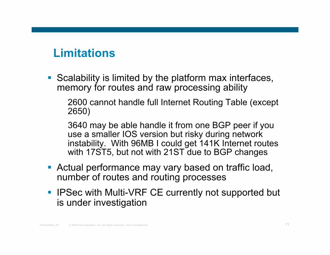
Limitations
Scalability is limited by the platform max interfaces, memory for routes and raw processing ability
2600 cannot handle full Internet Routing Table (except 2650) 3640 may be able handle it from one BGP peer if you use a smaller IOS version but risky during network instability. With 96MB I could get 141K Internet routes with 17ST5, but not with 21ST due to BGP changes
Actual performance may vary based on traffic load, number of routes and routing processes
IPSec with Multi-VRF CE currently not supported but is under investigation
© 2008 Cisco Systems, Inc. All rights reserved. Cisco Confidential Presentation_ID 72
Conclusions
Multi-VRF/VRF-Lite offers the following benefits: Only one CE router is needed facilitating provisioning and network management rather than a multiple CE router solution CE router has VRF functionality without full PE functionality to provide BGP routing tables
Note scalability factors Less routing updates to manage Overlapping Customer address spaces Can co-exist with an MPLS-based network but no MPLS enabled on CE
Note applicability example for branch offices with multiple networks
© 2008 Cisco Systems, Inc. All rights reserved. Cisco Confidential Presentation_ID 73
MPLS VPN Inter-Provider Solutions
MPLS workshop
© 2008 Cisco Systems, Inc. All rights reserved. Cisco Confidential Presentation_ID 74
Agenda
Inter-Provider Connectivity Options
Scaling Inter-Provider Solutions
Filtering & Route Distribution Mechanisms
Distribution of Traffic Load between Providers
© 2008 Cisco Systems, Inc. All rights reserved. Cisco Confidential Presentation_ID 75
VPN Client Connectivity
• VPN sites may be geographically dispersed requiring connectivity to separate MPLS VPN Service Providers
• Transit between VPN sites may pass through multiple providers MPLS VPN backbones
this implies exchange of VPN routing information between providers
• Referred to as Multi-Provider or Inter-Provider VPN
© 2008 Cisco Systems, Inc. All rights reserved. Cisco Confidential Presentation_ID 76
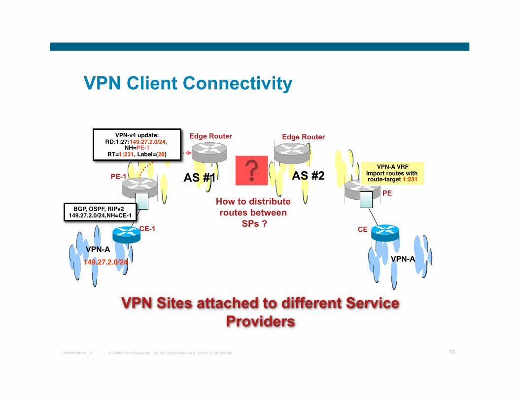
VPN Client Connectivity
VPN-A VPN-A
PE-1
PE
CE
Edge Router Edge Router
CE-1
VPN Sites attached to different Service Providers
AS #1 AS #2
149.27.2.0/24
VPN-v4 update:RD:1:27:149.27.2.0/24,
NH=PE-1 RT=1:231, Label=(28)
BGP, OSPF, RIPv2 149.27.2.0/24,NH=CE-1
VPN-A VRFImport routes with route-target 1:231
How to distribute routes between
SPs ?
© 2008 Cisco Systems, Inc. All rights reserved. Cisco Confidential Presentation_ID 77
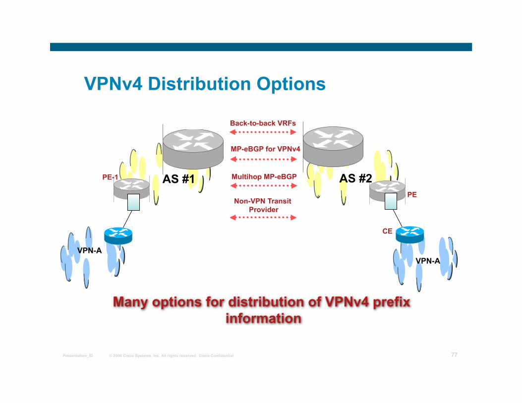
VPNv4 Distribution Options
VPN-A
PE-1
VPN-A
PE
CE
Back-to-back VRFs
MP-eBGP for VPNv4
Multihop MP-eBGP
Non-VPN Transit Provider
Many options for distribution of VPNv4 prefix information
AS #1 AS #2
© 2008 Cisco Systems, Inc. All rights reserved. Cisco Confidential Presentation_ID 78
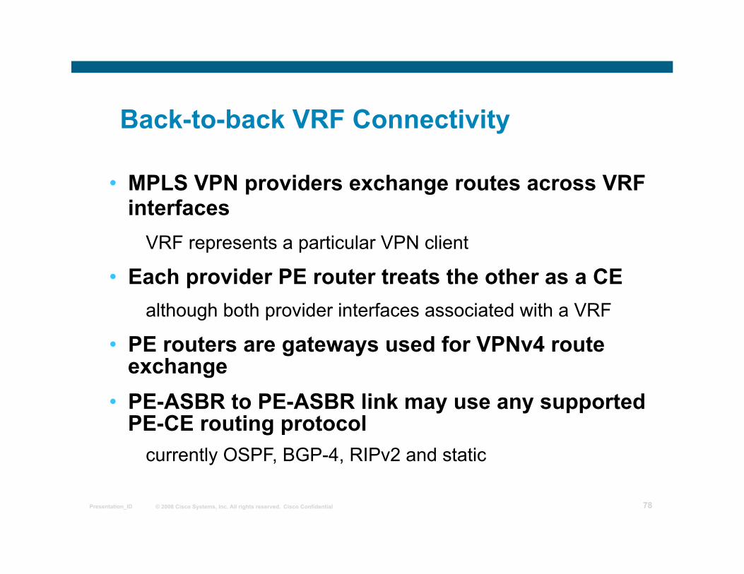
Back-to-back VRF Connectivity
• MPLS VPN providers exchange routes across VRF interfaces
VRF represents a particular VPN client
• Each provider PE router treats the other as a CE although both provider interfaces associated with a VRF
• PE routers are gateways used for VPNv4 route exchange
• PE-ASBR to PE-ASBR link may use any supported PE-CE routing protocol
currently OSPF, BGP-4, RIPv2 and static
© 2008 Cisco Systems, Inc. All rights reserved. Cisco Confidential Presentation_ID 79
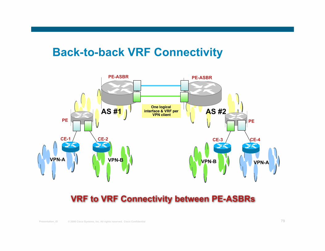
Back-to-back VRF Connectivity
VPN-A
PE
VPN-A
PE
CE-4
VPN-B
CE-2 CE-1 CE-3
VPN-B
VRF to VRF Connectivity between PE-ASBRs
One logical interface & VRF per
VPN client
PE-ASBR PE-ASBR
AS #1 AS #2
© 2008 Cisco Systems, Inc. All rights reserved. Cisco Confidential Presentation_ID 80
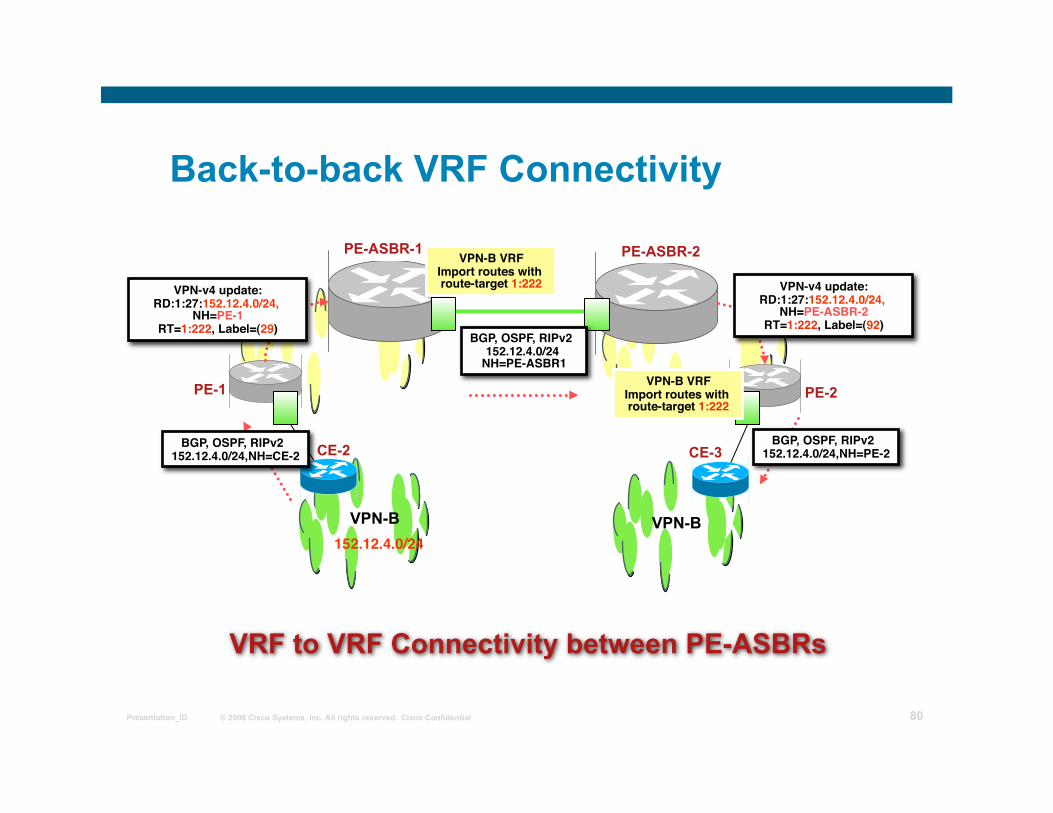
Back-to-back VRF Connectivity
PE-1 PE-2
VPN-B
CE-2 CE-3
VPN-B
VRF to VRF Connectivity between PE-ASBRs
PE-ASBR-1 PE-ASBR-2
152.12.4.0/24
BGP, OSPF, RIPv2 152.12.4.0/24,NH=CE-2
VPN-v4 update:RD:1:27:152.12.4.0/24,
NH=PE-1 RT=1:222, Label=(29)
VPN-B VRFImport routes with route-target 1:222
BGP, OSPF, RIPv2 152.12.4.0/24
NH=PE-ASBR1
VPN-v4 update:RD:1:27:152.12.4.0/24,
NH=PE-ASBR-2 RT=1:222, Label=(92)
VPN-B VRFImport routes with route-target 1:222
BGP, OSPF, RIPv2 152.12.4.0/24,NH=PE-2
© 2008 Cisco Systems, Inc. All rights reserved. Cisco Confidential Presentation_ID 81
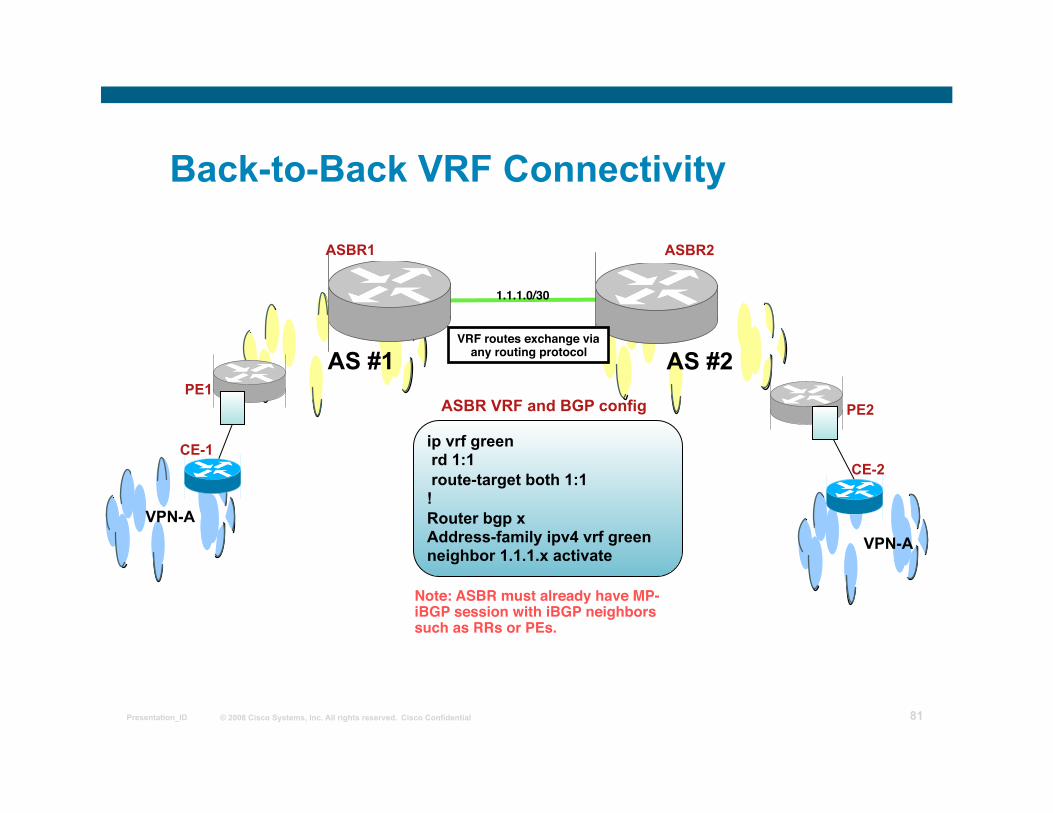
Back-to-Back VRF Connectivity
AS #1 AS #2 VRF routes exchange via
any routing protocol
Note: ASBR must already have MP-iBGP session with iBGP neighbors such as RRs or PEs.
1.1.1.0/30
ip vrf green rd 1:1 route-target both 1:1 ! Router bgp x Address-family ipv4 vrf green neighbor 1.1.1.x activate
ASBR VRF and BGP config
VPN-A
PE1
CE-1
VPN-A
CE-2
PE2
ASBR1 ASBR2
© 2008 Cisco Systems, Inc. All rights reserved. Cisco Confidential Presentation_ID 82
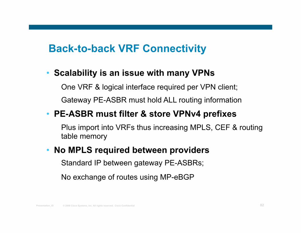
Back-to-back VRF Connectivity
• Scalability is an issue with many VPNs One VRF & logical interface required per VPN client;
Gateway PE-ASBR must hold ALL routing information
• PE-ASBR must filter & store VPNv4 prefixes Plus import into VRFs thus increasing MPLS, CEF & routing table memory
• No MPLS required between providers Standard IP between gateway PE-ASBRs;
No exchange of routes using MP-eBGP
© 2008 Cisco Systems, Inc. All rights reserved. Cisco Confidential Presentation_ID 83
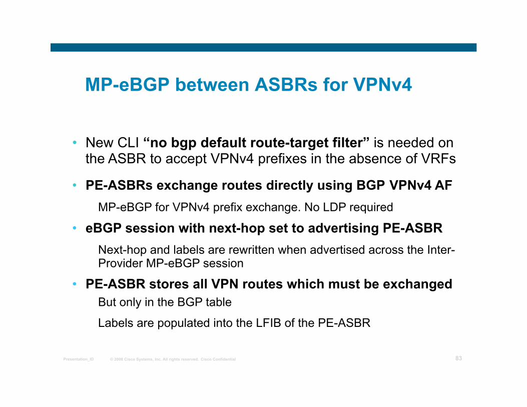
MP-eBGP between ASBRs for VPNv4
• New CLI “no bgp default route-target filter” is needed on the ASBR to accept VPNv4 prefixes in the absence of VRFs
• PE-ASBRs exchange routes directly using BGP VPNv4 AF MP-eBGP for VPNv4 prefix exchange. No LDP required
• eBGP session with next-hop set to advertising PE-ASBR Next-hop and labels are rewritten when advertised across the Inter-Provider MP-eBGP session
• PE-ASBR stores all VPN routes which must be exchanged But only in the BGP table
Labels are populated into the LFIB of the PE-ASBR
© 2008 Cisco Systems, Inc. All rights reserved. Cisco Confidential Presentation_ID 84
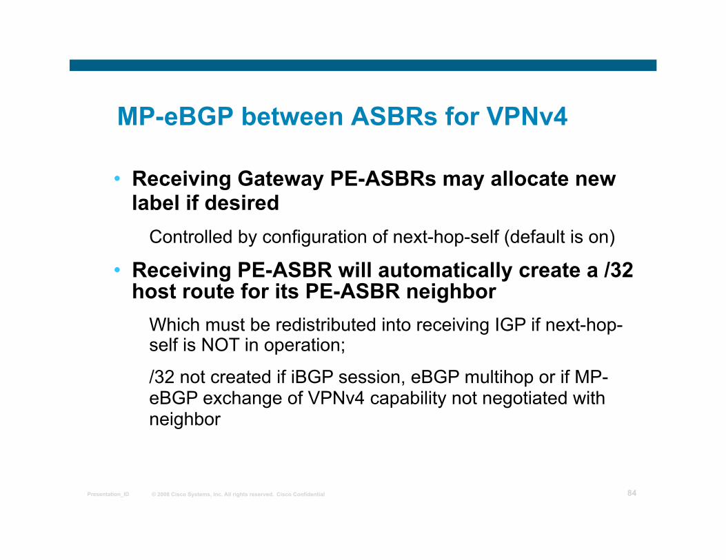
MP-eBGP between ASBRs for VPNv4
• Receiving Gateway PE-ASBRs may allocate new label if desired
Controlled by configuration of next-hop-self (default is on)
• Receiving PE-ASBR will automatically create a /32 host route for its PE-ASBR neighbor
Which must be redistributed into receiving IGP if next-hop-self is NOT in operation;
/32 not created if iBGP session, eBGP multihop or if MP-eBGP exchange of VPNv4 capability not negotiated with neighbor
© 2008 Cisco Systems, Inc. All rights reserved. Cisco Confidential Presentation_ID 85
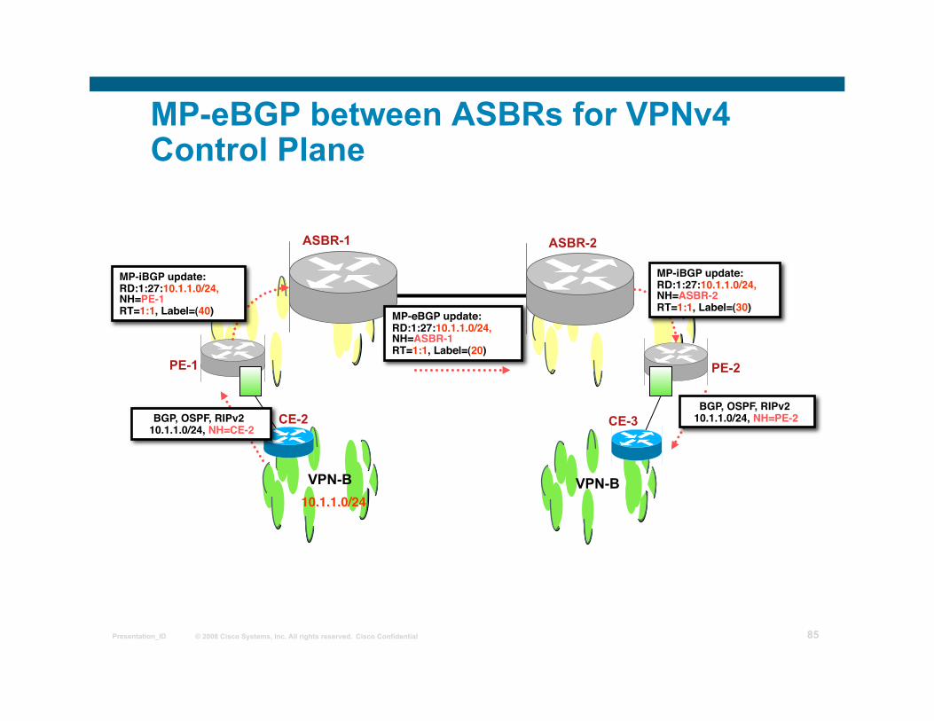
MP-eBGP between ASBRs for VPNv4 Control Plane
PE-1 PE-2
VPN-B
CE-2 CE-3
VPN-B
ASBR-1 ASBR-2
10.1.1.0/24
BGP, OSPF, RIPv2 10.1.1.0/24, NH=CE-2
MP-iBGP update:RD:1:27:10.1.1.0/24, NH=PE-1 RT=1:1, Label=(40)
MP-iBGP update:RD:1:27:10.1.1.0/24, NH=ASBR-2 RT=1:1, Label=(30)
BGP, OSPF, RIPv2 10.1.1.0/24, NH=PE-2
MP-eBGP update:RD:1:27:10.1.1.0/24, NH=ASBR-1 RT=1:1, Label=(20)
© 2008 Cisco Systems, Inc. All rights reserved. Cisco Confidential Presentation_ID 86
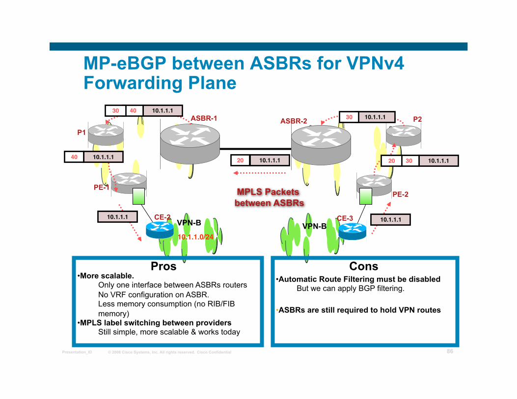
MP-eBGP between ASBRs for VPNv4 Forwarding Plane
PE-1 PE-2
VPN-B CE-2 CE-3
VPN-B
ASBR-1 ASBR-2
10.1.1.0/24
10.1.1.1
10.1.1.1 30
20 10.1.1.1 10.1.1.1 40
10.1.1.1
10.1.1.1 30 20
10.1.1.1 40 30
P1
P2
MPLS Packets between ASBRs
• More scalable. Only one interface between ASBRs routers No VRF configuration on ASBR. Less memory consumption (no RIB/FIB memory)
• MPLS label switching between providers Still simple, more scalable & works today
Pros Cons • Automatic Route Filtering must be disabled
But we can apply BGP filtering.
• ASBRs are still required to hold VPN routes
© 2008 Cisco Systems, Inc. All rights reserved. Cisco Confidential Presentation_ID 87
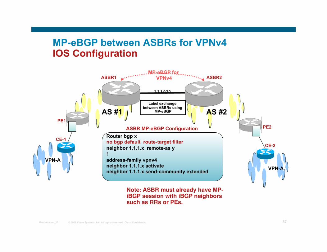
MP-eBGP between ASBRs for VPNv4 IOS Configuration
VPN-A
PE1
VPN-A
PE2
CE-2 CE-1
ASBR1 ASBR2
AS #1 AS #2
MP-eBGP for VPNv4
Label exchange between ASBRs using
MP-eBGP
1.1.1.0/30
Note: ASBR must already have MP-iBGP session with iBGP neighbors such as RRs or PEs.
Router bgp x no bgp default route-target filter neighbor 1.1.1.x remote-as y ! address-family vpnv4 neighbor 1.1.1.x activate neighbor 1.1.1.x send-community extended
ASBR MP-eBGP Configuration
© 2008 Cisco Systems, Inc. All rights reserved. Cisco Confidential Presentation_ID 88
Multihop MP-eBGP for VPNv4
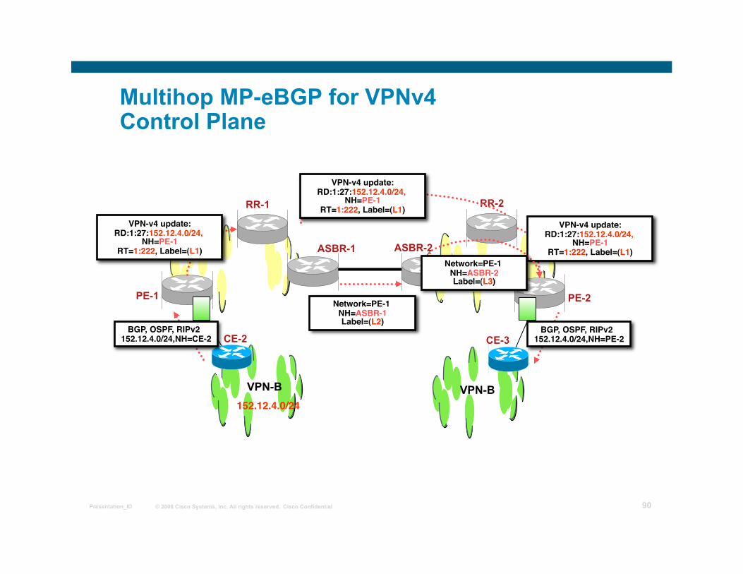
• MPLS VPN providers exchange VPNv4 prefixes via their Route Reflectors
Requires Multihop MP-eBGP (VPNv4 routes)
• Next-hop-self MUST be disabled on Route Reflector Preserves next-hop and label as allocated by the originating PE router
• Providers exchange IPv4 routes with labels between directly connected ASBRs using eBGP
Only PE loopback addresses exchanged as these are BGP next-hop addresses
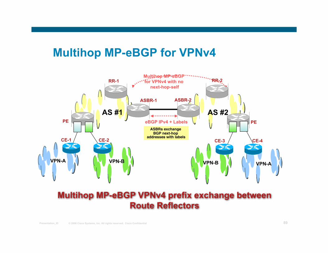
© 2008 Cisco Systems, Inc. All rights reserved. Cisco Confidential Presentation_ID 89
Multihop MP-eBGP for VPNv4
VPN-A
PE
VPN-A
PE
CE-4
VPN-B
CE-2 CE-1 CE-3
VPN-B
Multihop MP-eBGP VPNv4 prefix exchange between Route Reflectors
ASBR-1
RR-2
AS #1 AS #2
Multihop MP-eBGP for VPNv4 with no
next-hop-self
ASBRs exchange BGP next-hop
addresses with labels
ASBR-2
RR-1
eBGP IPv4 + Labels
© 2008 Cisco Systems, Inc. All rights reserved. Cisco Confidential Presentation_ID 90
Multihop MP-eBGP for VPNv4 Control Plane
PE-1 PE-2
VPN-B
CE-2 CE-3
VPN-B
ASBR-1
RR-2
SP #2
ASBR-2
RR-1
Network=PE-1 NH=ASBR-1 Label=(L2)
BGP, OSPF, RIPv2 152.12.4.0/24,NH=CE-2
152.12.4.0/24
VPN-v4 update:RD:1:27:152.12.4.0/24,
NH=PE-1 RT=1:222, Label=(L1)
VPN-v4 update:RD:1:27:152.12.4.0/24,
NH=PE-1 RT=1:222, Label=(L1)
VPN-v4 update:RD:1:27:152.12.4.0/24,
NH=PE-1 RT=1:222, Label=(L1)
BGP, OSPF, RIPv2 152.12.4.0/24,NH=PE-2
Network=PE-1 NH=ASBR-2 Label=(L3)
© 2008 Cisco Systems, Inc. All rights reserved. Cisco Confidential Presentation_ID 91
Multihop MP-eBGP for VPNv4 Forwarding Plane
PE-1 PE-2
VPN-B
CE-2 CE-3
VPN-B
ASBR-1
RR-2
ASBR-2
RR-1
152.12.4.0/24
152.12.4.1
L1 LDP PE-ASBR-2 Label L3
L1 152.12.4.1
152.12.4.1 L3
L2 L1 152.12.4.1
LDP PE-1 Label L1
152.12.4.1 152.12.4.1 L1
152.12.4.1
© 2008 Cisco Systems, Inc. All rights reserved. Cisco Confidential Presentation_ID 92
Multihop MP-eBGP for VPNv4 IOS Configuration
VPN-A
PE1
VPN-A
PE2
CE-2 CE-1
ASBR-1
RR-2
AS #1 AS #2
Multihop MP-eBGP for VPNv4 with
next-hop-unchange
ASBR-2
RR-1
eBGP IPv4 + Labels
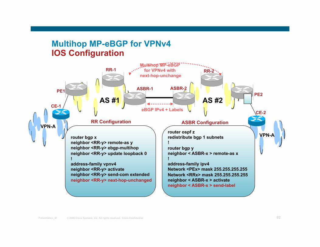
router ospf z redistribute bgp 1 subnets ! router bgp y neighbor < ASBR-x > remote-as x ! address-family ipv4 Network <PEx> mask 255.255.255.255 Network <RRx> mask 255.255.255.255 neighbor < ASBR-x > activate neighbor < ASBR-x > send-label
router bgp x neighbor <RR-y> remote-as y neighbor <RR-y> ebgp-multihop neighbor <RR-y> update loopback 0 ! address-family vpnv4 neighbor <RR-y> activate neighbor <RR-y> send-com extended neighbor <RR-y> next-hop-unchanged
RR Configuration ASBR Configuration
© 2008 Cisco Systems, Inc. All rights reserved. Cisco Confidential Presentation_ID 93
Multihop MP-eBGP for VPNv4
• Improves the scalability of route exchange Eliminates the requirement to hold VPNv4 routes on the ASBRs;
Route reflectors already store VPNv4 prefix information
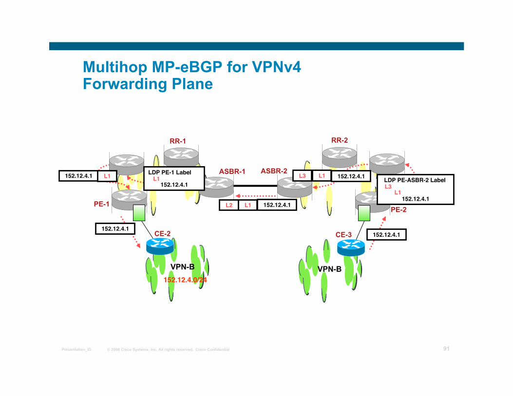
• Packets travel with 3 level label stack <LDP IGP, BGP learnt label for Next-hop, VPN label>
• Advertising PE addresses to another AS may not be acceptable to few providers.
© 2008 Cisco Systems, Inc. All rights reserved. Cisco Confidential Presentation_ID 94
Non-VPN Transit Provider
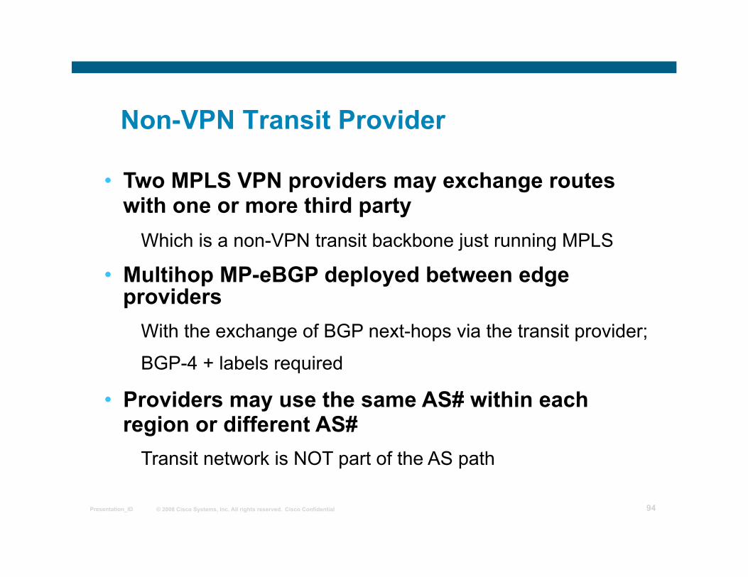
• Two MPLS VPN providers may exchange routes with one or more third party
Which is a non-VPN transit backbone just running MPLS
• Multihop MP-eBGP deployed between edge providers
With the exchange of BGP next-hops via the transit provider;
BGP-4 + labels required
• Providers may use the same AS# within each region or different AS#
Transit network is NOT part of the AS path
© 2008 Cisco Systems, Inc. All rights reserved. Cisco Confidential Presentation_ID 95
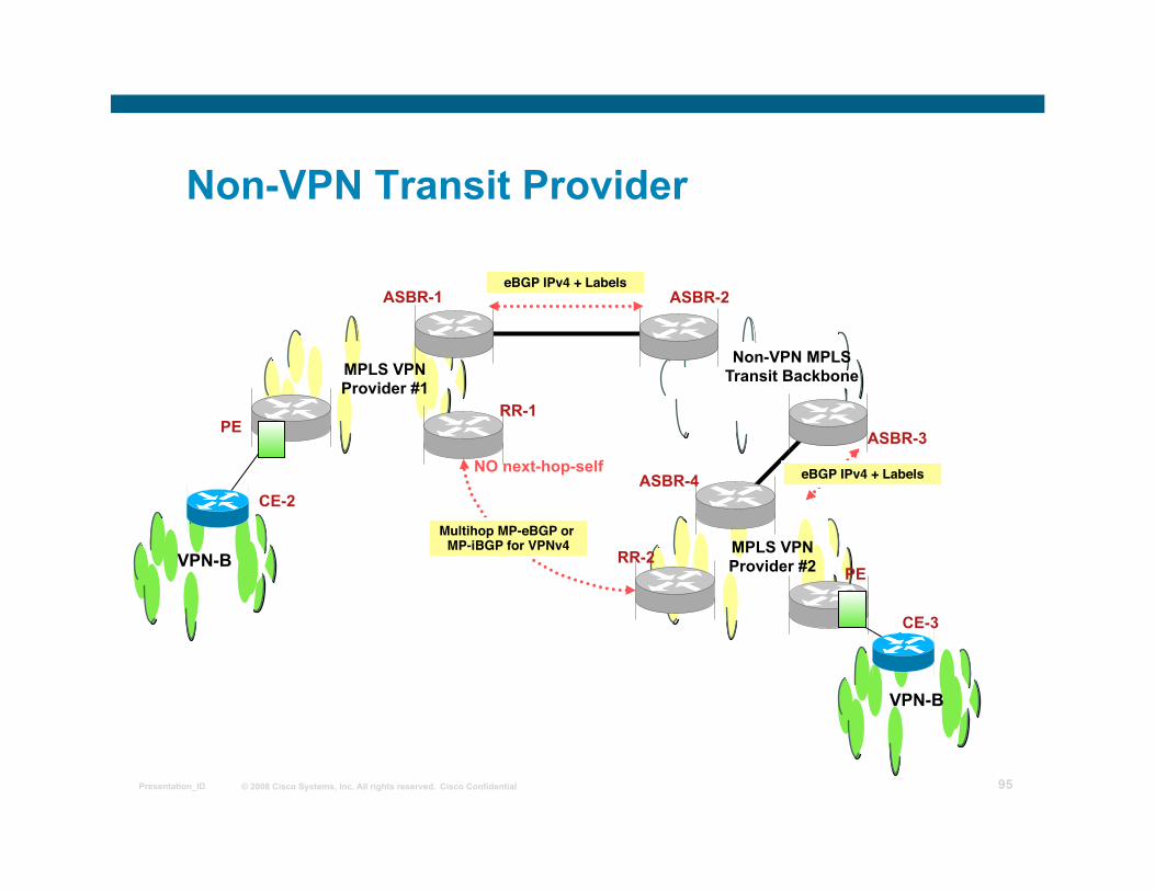
Non-VPN Transit Provider
PE
PE VPN-B
CE-2
CE-3
VPN-B
ASBR-1
RR-2
Non-VPN MPLS Transit Backbone
Multihop MP-eBGP or MP-iBGP for VPNv4
ASBR-2
RR-1 ASBR-3
ASBR-4 NO next-hop-self
eBGP IPv4 + Labels
eBGP IPv4 + Labels
MPLS VPN Provider #1
MPLS VPN Provider #2
© 2008 Cisco Systems, Inc. All rights reserved. Cisco Confidential Presentation_ID 96
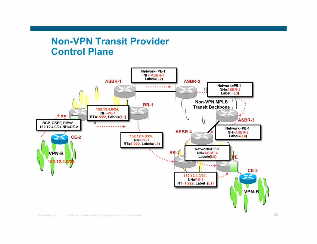
Non-VPN Transit Provider Control Plane
PE
PE VPN-B
CE-2
CE-3
VPN-B
ASBR-1
RR-2
Non-VPN MPLS Transit Backbone
ASBR-2
RR-1
ASBR-3
ASBR-4
MPLS VPN Provider #2
152.12.4.0/24
BGP, OSPF, RIPv2 152.12.4.0/24,NH=CE-2
152.12.4.0/24, NH=PE-1
RT=1:222, Label=(L1)
Network=PE-1 NH=ASBR-1 Label=(L2)
152.12.4.0/24, NH=PE-1
RT=1:222, Label=(L1)
152.12.4.0/24, NH=PE-1
RT=1:222, Label=(L1)
Network=PE-1 NH=ASBR-2 Label=(L3)
Network=PE-1 NH=ASBR-3 Label=(L4)
Network=PE-1 NH=ASBR-4 Label=(L5)
© 2008 Cisco Systems, Inc. All rights reserved. Cisco Confidential Presentation_ID 97
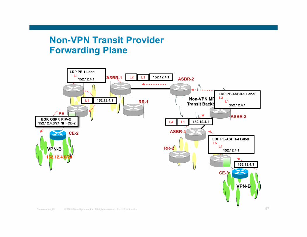
Non-VPN Transit Provider Forwarding Plane
PE
PE VPN-B
CE-2
CE-3
VPN-B
ASBR-1
RR-2
Non-VPN MPLS Transit Backbone
ASBR-2
RR-1
ASBR-3
ASBR-4
152.12.4.0/24
BGP, OSPF, RIPv2 152.12.4.0/24,NH=CE-2
152.12.4.1
LDP PE-ASBR-4 Label L5
L1 152.12.4.1
152.12.4.1 L1 L4
LDP PE-ASBR-2 Label L3
L1 152.12.4.1
L1 L2 152.12.4.1 LDP PE-1 Label
L1 152.12.4.1
L1 152.12.4.1
© 2008 Cisco Systems, Inc. All rights reserved. Cisco Confidential Presentation_ID 98
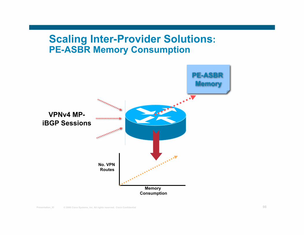
Scaling Inter-Provider Solutions: PE-ASBR Memory Consumption
VPNv4 MP-iBGP Sessions
PE-ASBR Memory
No. VPN Routes
Memory Consumption
© 2008 Cisco Systems, Inc. All rights reserved. Cisco Confidential Presentation_ID 99
PE-ASBR Memory Scaling • Potentially large amounts of VPN routing
information That may or may not need to be carried between providers;
Large percentage will be local VPN prefixes
This is specially true for (1)back-back vrf (2)MP-eBGP on PE-ASBR
• PE-ASBRs must hold relevant VPN routing information
But only Inter-AS VPN prefix details
• Two methods available to aid scaling ARF with local VRF import (default)
ARF disabled with inbound filtering
© 2008 Cisco Systems, Inc. All rights reserved. Cisco Confidential Presentation_ID 100
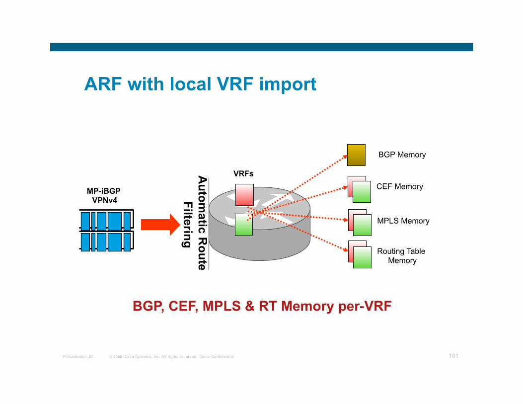
ARF with local VRF import
• Automatic Route Filtering (ARF) for non-imported routes
If RT does not match locally configured import statement then drop the route
• Each PE-ASBR holds VRFs for Inter-AS VPNs And imports routes based on route-target values
• PE-ASBR acts like normal PE router Although also services external MP-BGP sessions
© 2008 Cisco Systems, Inc. All rights reserved. Cisco Confidential Presentation_ID 101
ARF with local VRF import
BGP Memory
VRFs CEF Memory
MPLS Memory
Routing Table Memory
MP-iBGP VPNv4
Autom
atic Route
Filtering
BGP, CEF, MPLS & RT Memory per-VRF
© 2008 Cisco Systems, Inc. All rights reserved. Cisco Confidential Presentation_ID 102
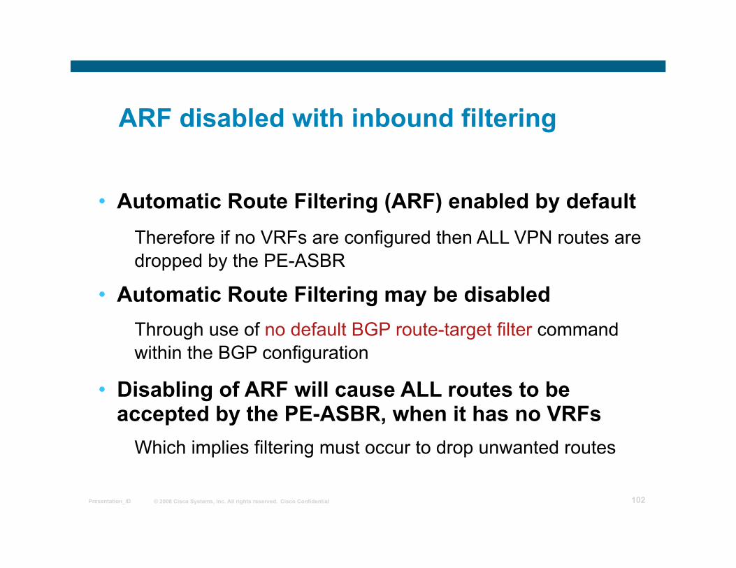
ARF disabled with inbound filtering
• Automatic Route Filtering (ARF) enabled by default Therefore if no VRFs are configured then ALL VPN routes are dropped by the PE-ASBR
• Automatic Route Filtering may be disabled Through use of no default BGP route-target filter command within the BGP configuration
• Disabling of ARF will cause ALL routes to be accepted by the PE-ASBR, when it has no VRFs
Which implies filtering must occur to drop unwanted routes
© 2008 Cisco Systems, Inc. All rights reserved. Cisco Confidential Presentation_ID 103
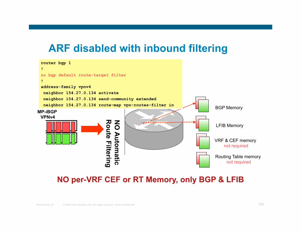
ARF disabled with inbound filtering
BGP Memory MP-iBGP
VPNv4 NO
Autom
atic R
oute Filtering
router bgp 1 ! no bgp default route-target filter ! address-family vpnv4 neighbor 154.27.0.134 activate neighbor 154.27.0.134 send-community extended neighbor 154.27.0.134 route-map vpn-routes-filter in
LFIB Memory
VRF & CEF memory not required
Routing Table memory not required
© 2008 Cisco Systems, Inc. All rights reserved. Cisco Confidential Presentation_ID 104
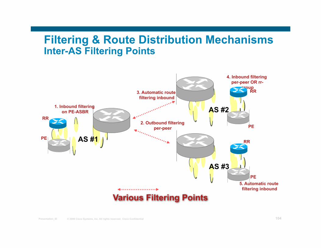
Filtering & Route Distribution Mechanisms Inter-AS Filtering Points
PE
PE
RR
2. Outbound filtering per-peer
4. Inbound filtering per-peer OR rr-
group
1. Inbound filtering on PE-ASBR
3. Automatic route filtering inbound
Various Filtering Points
AS #1
AS #2 RR
RR
AS #3 PE
5. Automatic route filtering inbound
© 2008 Cisco Systems, Inc. All rights reserved. Cisco Confidential Presentation_ID 105
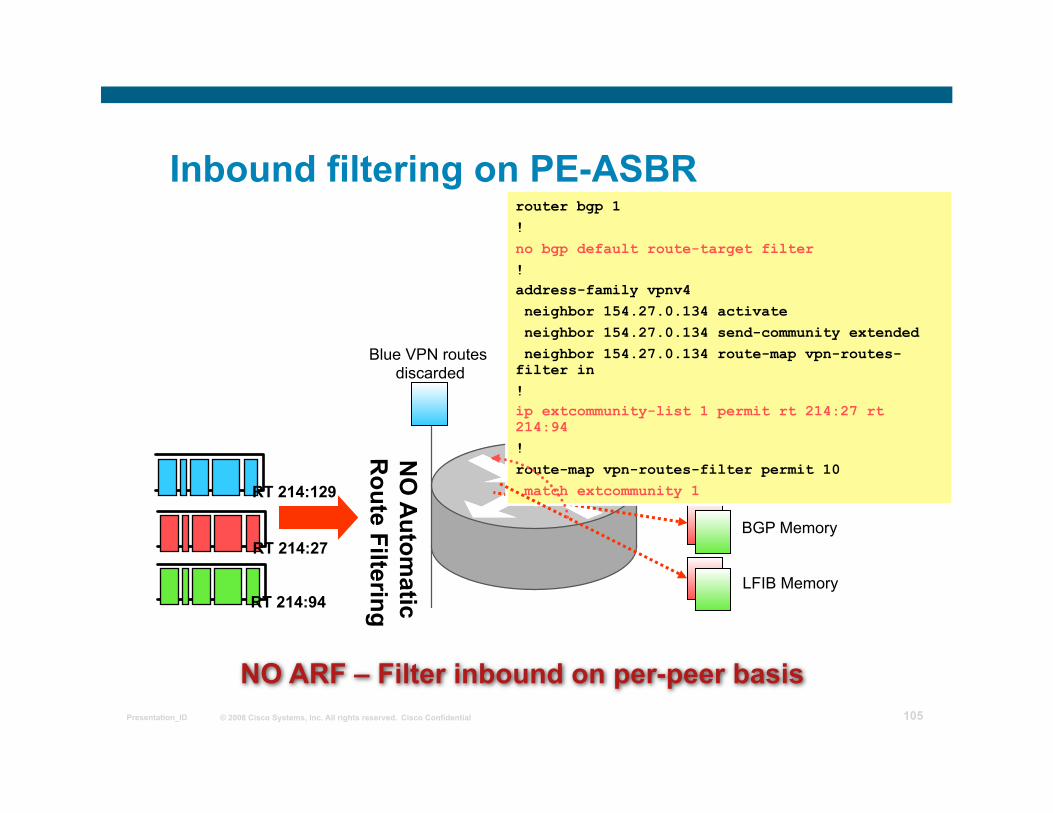
Inbound filtering on PE-ASBR
BGP Memory RT 214:27
NO
Autom
atic R
oute Filtering NO ARF – Filter inbound on per-peer basis
router bgp 1 ! no bgp default route-target filter ! address-family vpnv4 neighbor 154.27.0.134 activate neighbor 154.27.0.134 send-community extended neighbor 154.27.0.134 route-map vpn-routes-filter in ! ip extcommunity-list 1 permit rt 214:27 rt 214:94 ! route-map vpn-routes-filter permit 10 match extcommunity 1
LFIB Memory RT 214:94
Blue VPN routes discarded
RT 214:129
© 2008 Cisco Systems, Inc. All rights reserved. Cisco Confidential Presentation_ID 106
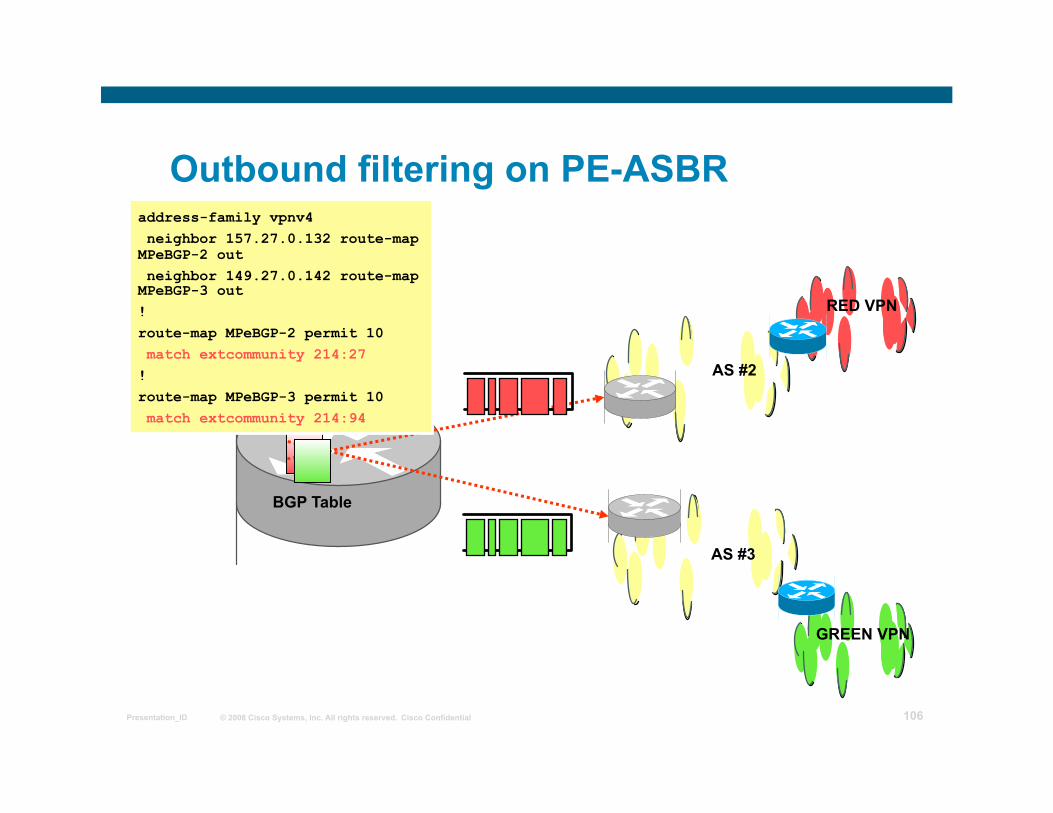
Outbound filtering on PE-ASBR
BGP Table
address-family vpnv4 neighbor 157.27.0.132 route-map MPeBGP-2 out neighbor 149.27.0.142 route-map MPeBGP-3 out ! route-map MPeBGP-2 permit 10 match extcommunity 214:27 ! route-map MPeBGP-3 permit 10 match extcommunity 214:94
RED VPN
GREEN VPN
AS #3
AS #2
© 2008 Cisco Systems, Inc. All rights reserved. Cisco Confidential Presentation_ID 107
Downstream RT allocation
• Both inbound & outbound filtering restrictive with large number of VPN clients
As each RT must be known and the filters must be established
• Changes to VPN client membership will cause configuration changes on PE-ASBRs
As each filter must be updated to reflect addition/deletion of VPN clients
• With large number of clients a simplified filtering scheme is needed
Provided with “Downstream provider RT allocation” scheme
© 2008 Cisco Systems, Inc. All rights reserved. Cisco Confidential Presentation_ID 108
Downstream RT allocation
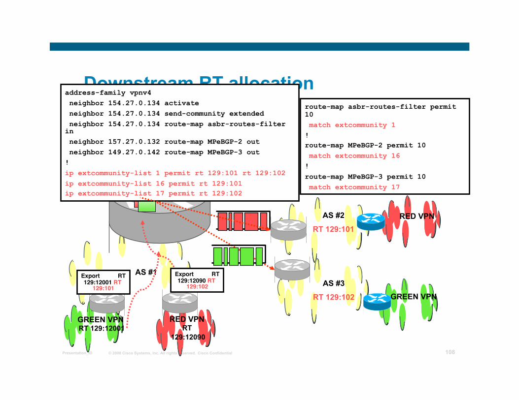
RED VPN
AS #3
RT 129:102
AS #1
GREEN VPN
RED VPN RT
129:12090
GREEN VPN RT 129:12001
address-family vpnv4 neighbor 154.27.0.134 activate neighbor 154.27.0.134 send-community extended neighbor 154.27.0.134 route-map asbr-routes-filter in neighbor 157.27.0.132 route-map MPeBGP-2 out neighbor 149.27.0.142 route-map MPeBGP-3 out ! ip extcommunity-list 1 permit rt 129:101 rt 129:102 ip extcommunity-list 16 permit rt 129:101 ip extcommunity-list 17 permit rt 129:102
Export RT 129:12090 RT
129:102 Export RT 129:12001 RT
129:101
AS #2
RT 129:101
route-map asbr-routes-filter permit 10 match extcommunity 1 ! route-map MPeBGP-2 permit 10 match extcommunity 16 ! route-map MPeBGP-3 permit 10 match extcommunity 17
© 2008 Cisco Systems, Inc. All rights reserved. Cisco Confidential Presentation_ID 109
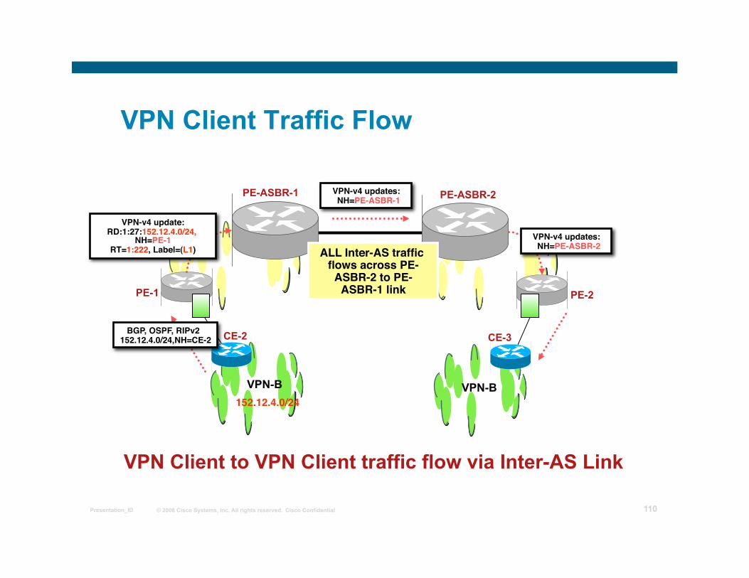
Distribution of Traffic Load between Providers
• Balancing of Inter-AS traffic is an important issue For distribution of traffic and redundancy of network design
• All Inter-AS traffic must pass through PE-ASBRs As BGP next-hops are reachable via these routers
• Multiple links provide traffic distribution But do not provide redundancy due to single point of failure of the PE-ASBR
© 2008 Cisco Systems, Inc. All rights reserved. Cisco Confidential Presentation_ID 110
VPN Client Traffic Flow
PE-1 PE-2
VPN-B
CE-2 CE-3
VPN-B
PE-ASBR-1 PE-ASBR-2
152.12.4.0/24
BGP, OSPF, RIPv2 152.12.4.0/24,NH=CE-2
VPN-v4 update:RD:1:27:152.12.4.0/24,
NH=PE-1 RT=1:222, Label=(L1)
VPN-v4 updates: NH=PE-ASBR-1
VPN-v4 updates: NH=PE-ASBR-2 ALL Inter-AS traffic
flows across PE-ASBR-2 to PE-
ASBR-1 link
VPN Client to VPN Client traffic flow via Inter-AS Link
© 2008 Cisco Systems, Inc. All rights reserved. Cisco Confidential Presentation_ID 111
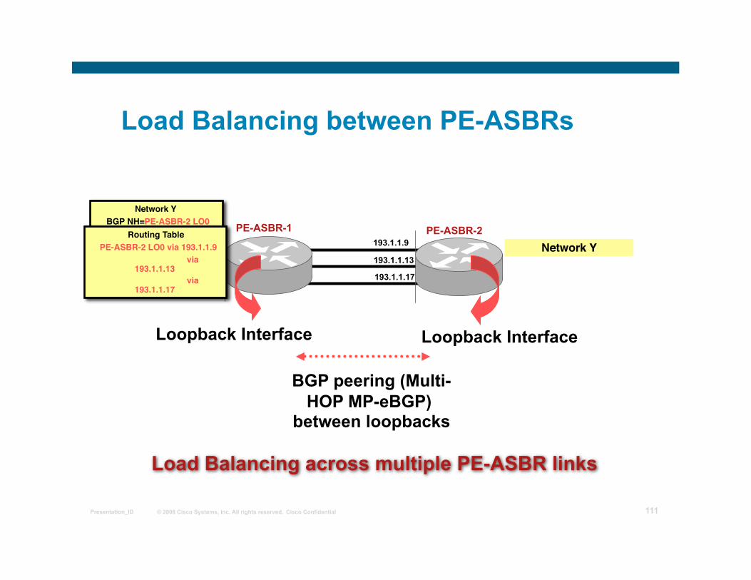
Load Balancing between PE-ASBRs
PE-ASBR-1
Network Y BGP NH=PE-ASBR-2 LO0
Network Y PE-ASBR-2
Loopback Interface Loopback Interface
BGP peering (Multi-HOP MP-eBGP)
between loopbacks
Routing Table PE-ASBR-2 LO0 via 193.1.1.9
via 193.1.1.13
via 193.1.1.17
193.1.1.9
193.1.1.13
193.1.1.17
Load Balancing across multiple PE-ASBR links
© 2008 Cisco Systems, Inc. All rights reserved. Cisco Confidential Presentation_ID 112
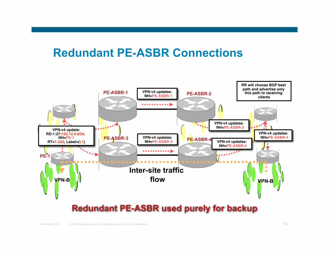
Redundant PE-ASBR Connections
PE-ASBR-1 PE-ASBR-2
PE-ASBR-3 PE-ASBR-4
PE-1
VPN-v4 updates: NH=PE-ASBR-1
VPN-v4 updates: NH=PE-ASBR-3
VPN-v4 updates: NH=PE-ASBR-2
VPN-v4 updates: NH=PE-ASBR-4
RR will choose BGP best path and advertise only
this path to receiving clients
VPN-v4 updates: NH=PE-ASBR-4
VPN-v4 update:RD:1:27:152.12.4.0/24,
NH=PE-1 RT=1:222, Label=(L1)
VPN-B VPN-B
Inter-site traffic flow
Redundant PE-ASBR used purely for backup
© 2008 Cisco Systems, Inc. All rights reserved. Cisco Confidential Presentation_ID 113
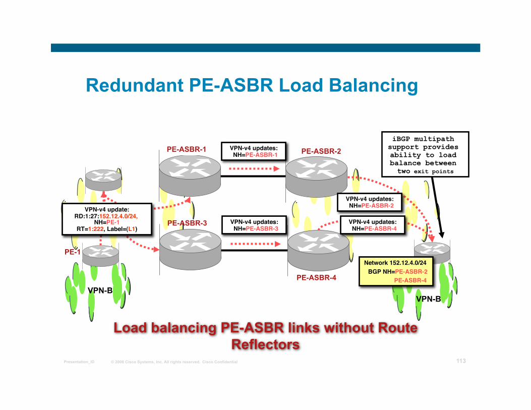
Redundant PE-ASBR Load Balancing
PE-ASBR-1 PE-ASBR-2
PE-ASBR-3
PE-ASBR-4
PE-1
VPN-v4 updates: NH=PE-ASBR-1
VPN-v4 updates: NH=PE-ASBR-3
VPN-v4 updates: NH=PE-ASBR-2
VPN-v4 updates: NH=PE-ASBR-4
iBGP multipath support provides ability to load balance between two exit points
VPN-v4 update:RD:1:27:152.12.4.0/24,
NH=PE-1 RT=1:222, Label=(L1)
VPN-B VPN-B
Load balancing PE-ASBR links without Route Reflectors
Network 152.12.4.0/24 BGP NH=PE-ASBR-2 PE-ASBR-4
© 2008 Cisco Systems, Inc. All rights reserved. Cisco Confidential Presentation_ID 114
Internet Access from a VPN
© 2008 Cisco Systems, Inc. All rights reserved. Cisco Confidential Presentation_ID 115
Overview
Leaking Between VPN and Global Backbone Routing Separating Internet Access from VPN Service
Internet Access Backbone as a Separate VPN Internet Access with VRF Aware NAT
© 2008 Cisco Systems, Inc. All rights reserved. Cisco Confidential Presentation_ID 116
Leaking Between VPN and Global Backbone Routing
© 2008 Cisco Systems, Inc. All rights reserved. Cisco Confidential Presentation_ID 117
Internet Access Through Global Routing
Two implementation options: Internet access is implemented via separate
interfaces that are not placed in any VRF (traditional Internet access setup)
Packet leaking between a VRF and the global table is achieved through special configuration commands
© 2008 Cisco Systems, Inc. All rights reserved. Cisco Confidential Presentation_ID 118
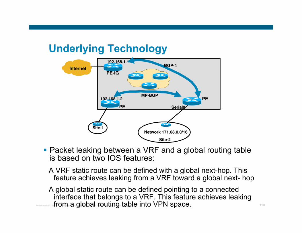
Underlying Technology
Packet leaking between a VRF and a global routing table is based on two IOS features:
A VRF static route can be defined with a global next-hop. This feature achieves leaking from a VRF toward a global next- hop
A global static route can be defined pointing to a connected interface that belongs to a VRF. This feature achieves leaking from a global routing table into VPN space.
PE PE
Internet
Site-1
PE-IG
Site-2 Network 171.68.0.0/16
Serial0
192.168.1.1
192.168.1.2
BGP-4
MP-BGP
© 2008 Cisco Systems, Inc. All rights reserved. Cisco Confidential Presentation_ID 119
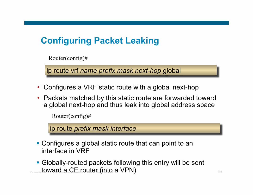
Configuring Packet Leaking
Configures a global static route that can point to an interface in VRF
Globally-routed packets following this entry will be sent toward a CE router (into a VPN)
Router(config)#
ip route vrf name prefix mask next-hop global
• Configures a VRF static route with a global next-hop • Packets matched by this static route are forwarded toward
a global next-hop and thus leak into global address space Router(config)#
ip route prefix mask interface
© 2008 Cisco Systems, Inc. All rights reserved. Cisco Confidential Presentation_ID 120
Designing Internet Access Through Packet Leaking
A public address is assigned to an Internet/VPN customer
A global static route for an assigned address block is configured on the PE router
The static route has to be redistributed into BGP to provide full connectivity to the customer
A default route toward a global Internet exit point is installed in the customer VRF
This default route is used to forward packets to unknown destinations (Internet) into the global address space
© 2008 Cisco Systems, Inc. All rights reserved. Cisco Confidential Presentation_ID 121
Connectivity from the Customer to the Internet
A default route is installed into the VRF pointing to a global Internet gateway
Warning: Using a default route for Internet routing does NOT allow any other default route for intra-VPN routing
The default route is not part of any VPN A single label is used for packets forwarded toward the global next-
hop
The label used for packet forwarding is the IGP label (TDP/LDP-assigned label) corresponding to the IP address of the global next-hop
© 2008 Cisco Systems, Inc. All rights reserved. Cisco Confidential Presentation_ID 122
VRF-Specific Default Route
The Internet gateway specified as the next-hop in the VRF default route need NOT to be directly connected
The next-hop can be in the upstream AS to achieve redundancy
Different Internet gateways can be used for different VRFs
© 2008 Cisco Systems, Inc. All rights reserved. Cisco Confidential Presentation_ID 123
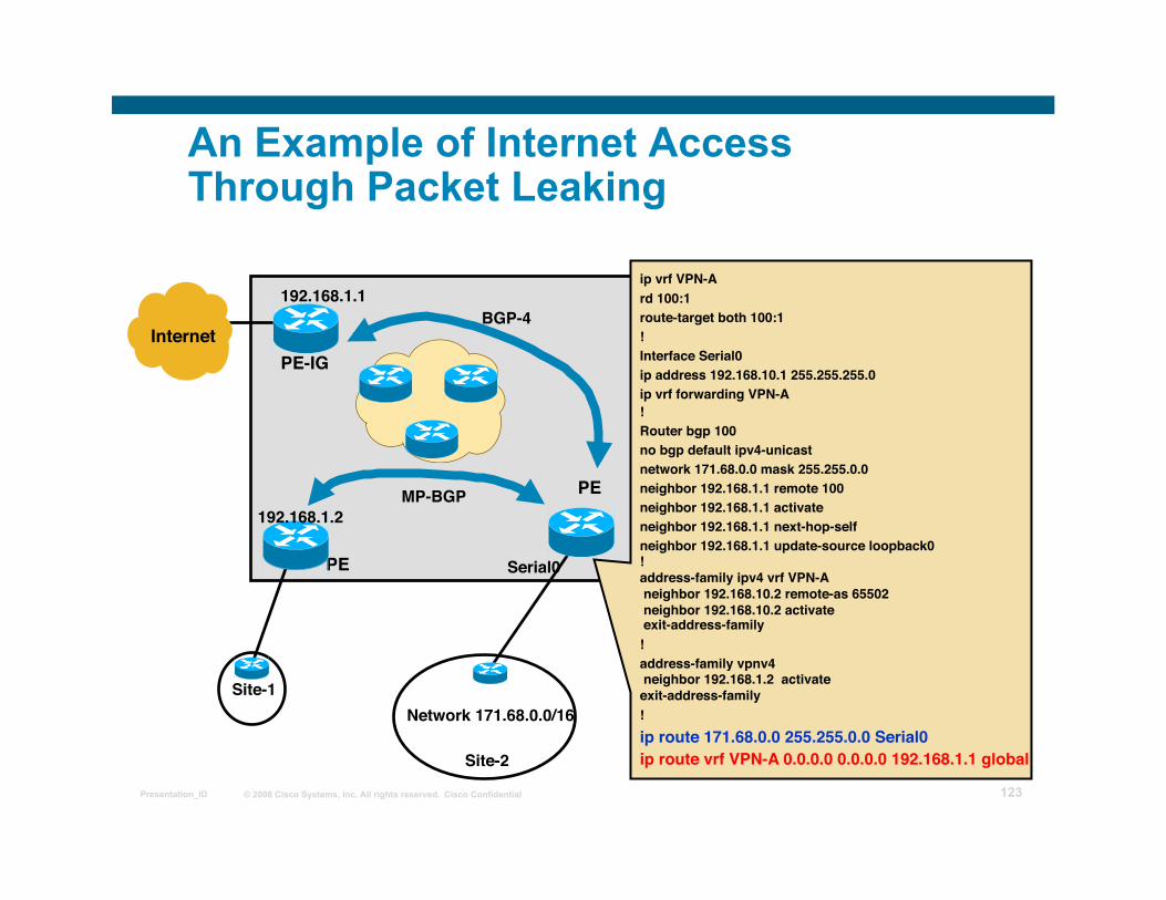
An Example of Internet Access Through Packet Leaking
PE
PE
Internet
Site-1
PE-IG
Site-2
Network 171.68.0.0/16
Serial0
192.168.1.1
192.168.1.2
ip vrf VPN-A rd 100:1 route-target both 100:1 ! Interface Serial0 ip address 192.168.10.1 255.255.255.0 ip vrf forwarding VPN-A ! Router bgp 100 no bgp default ipv4-unicast network 171.68.0.0 mask 255.255.0.0 neighbor 192.168.1.1 remote 100 neighbor 192.168.1.1 activate neighbor 192.168.1.1 next-hop-self neighbor 192.168.1.1 update-source loopback0 ! address-family ipv4 vrf VPN-A neighbor 192.168.10.2 remote-as 65502 neighbor 192.168.10.2 activate exit-address-family ! address-family vpnv4 neighbor 192.168.1.2 activate exit-address-family ! ip route 171.68.0.0 255.255.0.0 Serial0 ip route vrf VPN-A 0.0.0.0 0.0.0.0 192.168.1.1 global
BGP-4
MP-BGP
© 2008 Cisco Systems, Inc. All rights reserved. Cisco Confidential Presentation_ID 124
IP packetD=cisco.com
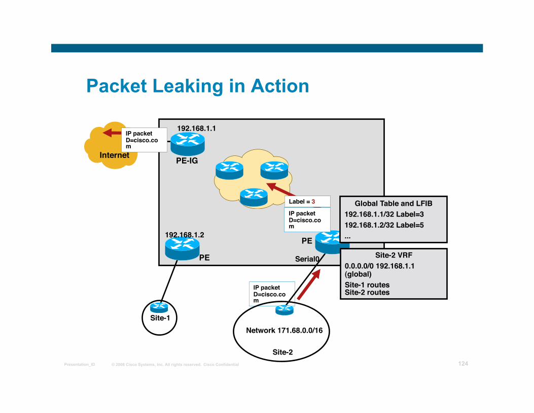
Packet Leaking in Action
PE
PE
Internet
Site-1
PE-IG
Site-2
Network 171.68.0.0/16
Serial0
192.168.1.1
192.168.1.2
Site-2 VRF 0.0.0.0/0 192.168.1.1 (global) Site-1 routesSite-2 routes
Global Table and LFIB 192.168.1.1/32 Label=3 192.168.1.2/32 Label=5 ...
Label = 3
IP packetD=cisco.com
IP packetD=cisco.com
© 2008 Cisco Systems, Inc. All rights reserved. Cisco Confidential Presentation_ID 125
Redundant Internet Access with Packet Leaking
Several VRF default routes can be used with different next-hops
This setup will survive failure of the Internet gateway, not the failure of its upstream link
Global next-hop can be in an upstream autonomous system
This setup yields best redundancy because it tests availability of the whole path from PE router to the upstream autonomous system
Drawback: local Internet service stops working if the upstream autonomous system is not reachable
© 2008 Cisco Systems, Inc. All rights reserved. Cisco Confidential Presentation_ID 126
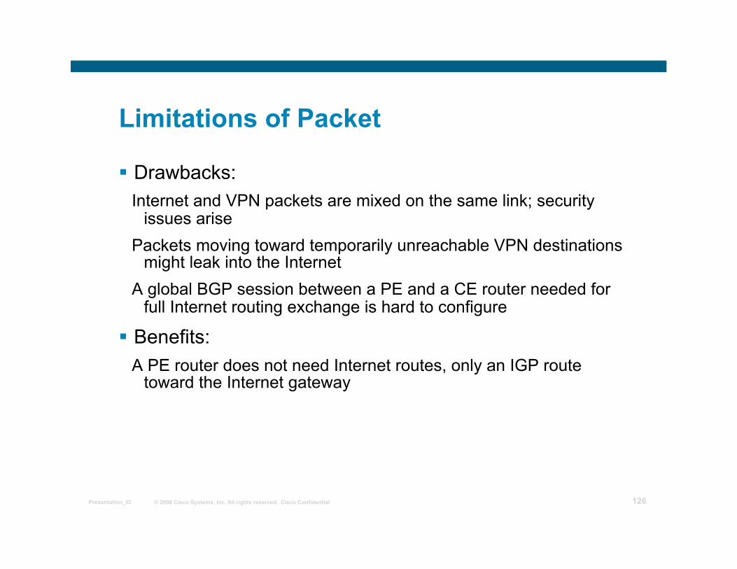
Limitations of Packet Leaking
Drawbacks: Internet and VPN packets are mixed on the same link; security
issues arise Packets moving toward temporarily unreachable VPN destinations
might leak into the Internet A global BGP session between a PE and a CE router needed for
full Internet routing exchange is hard to configure
Benefits: A PE router does not need Internet routes, only an IGP route
toward the Internet gateway

© 2008 Cisco Systems, Inc. All rights reserved. Cisco Confidential Presentation_ID 127
Separating Internet Access from VPN Service
© 2008 Cisco Systems, Inc. All rights reserved. Cisco Confidential Presentation_ID 128
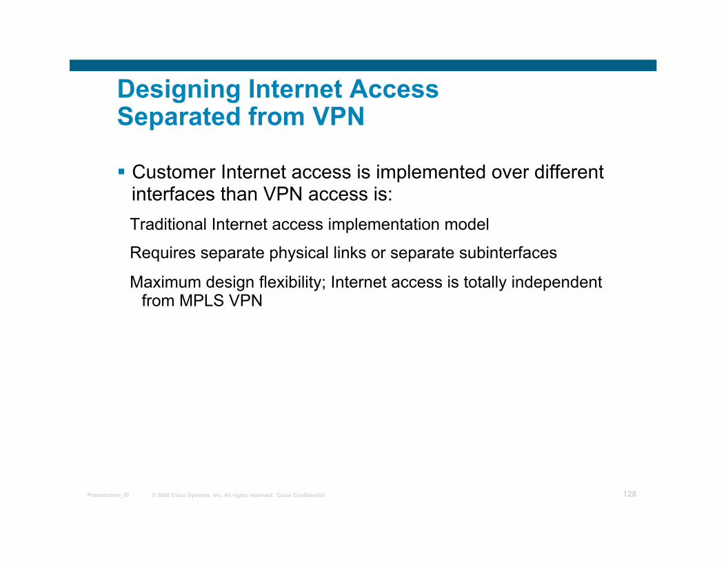
Designing Internet Access Separated from VPN
Customer Internet access is implemented over different interfaces than VPN access is:
Traditional Internet access implementation model
Requires separate physical links or separate subinterfaces
Maximum design flexibility; Internet access is totally independent from MPLS VPN
© 2008 Cisco Systems, Inc. All rights reserved. Cisco Confidential Presentation_ID 129
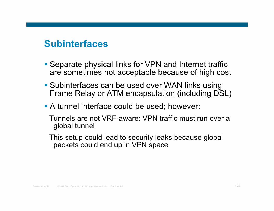
Implementing Separate Subinterfaces
Separate physical links for VPN and Internet traffic are sometimes not acceptable because of high cost
Subinterfaces can be used over WAN links using Frame Relay or ATM encapsulation (including DSL)
A tunnel interface could be used; however: Tunnels are not VRF-aware: VPN traffic must run over a
global tunnel This setup could lead to security leaks because global
packets could end up in VPN space
© 2008 Cisco Systems, Inc. All rights reserved. Cisco Confidential Presentation_ID 130
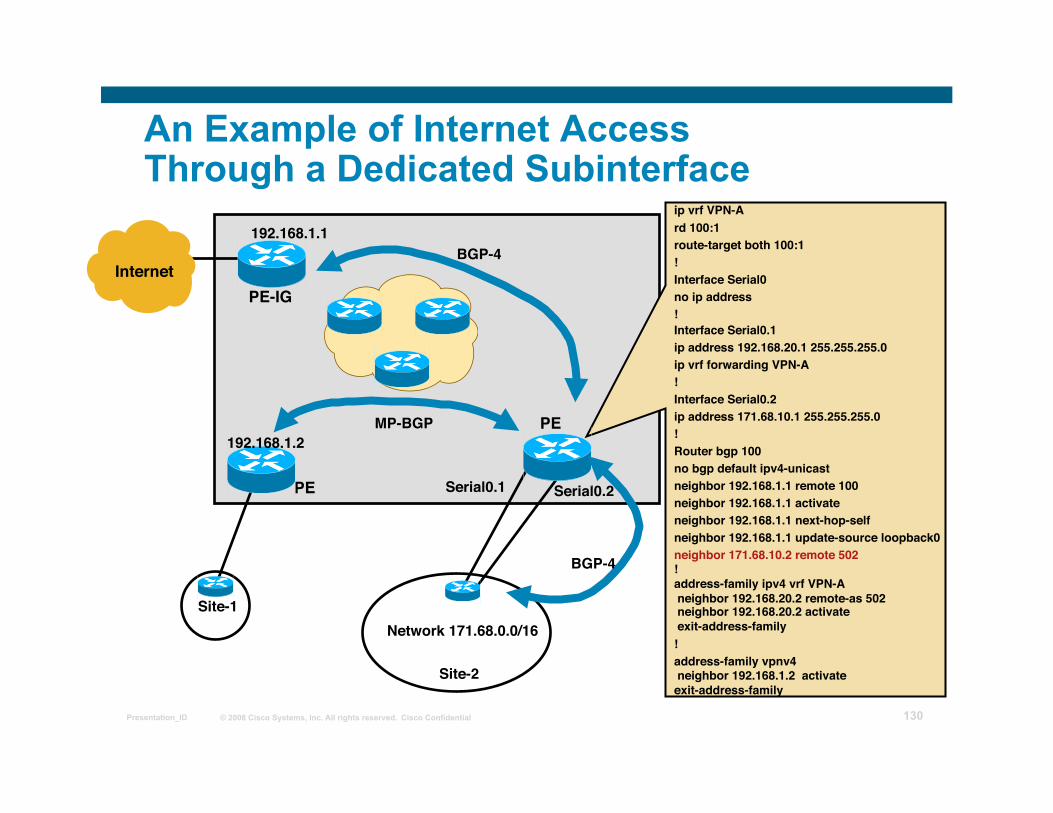
An Example of Internet Access Through a Dedicated Subinterface
PE
PE
Internet
Site-1
PE-IG
Site-2
Network 171.68.0.0/16
Serial0.1
192.168.1.1
192.168.1.2
ip vrf VPN-A rd 100:1 route-target both 100:1 ! Interface Serial0 no ip address ! Interface Serial0.1 ip address 192.168.20.1 255.255.255.0 ip vrf forwarding VPN-A ! Interface Serial0.2 ip address 171.68.10.1 255.255.255.0 ! Router bgp 100 no bgp default ipv4-unicast neighbor 192.168.1.1 remote 100 neighbor 192.168.1.1 activate neighbor 192.168.1.1 next-hop-self neighbor 192.168.1.1 update-source loopback0 neighbor 171.68.10.2 remote 502 ! address-family ipv4 vrf VPN-A neighbor 192.168.20.2 remote-as 502 neighbor 192.168.20.2 activate exit-address-family ! address-family vpnv4 neighbor 192.168.1.2 activate exit-address-family
BGP-4
MP-BGP
Serial0.2
BGP-4
© 2008 Cisco Systems, Inc. All rights reserved. Cisco Confidential Presentation_ID 131
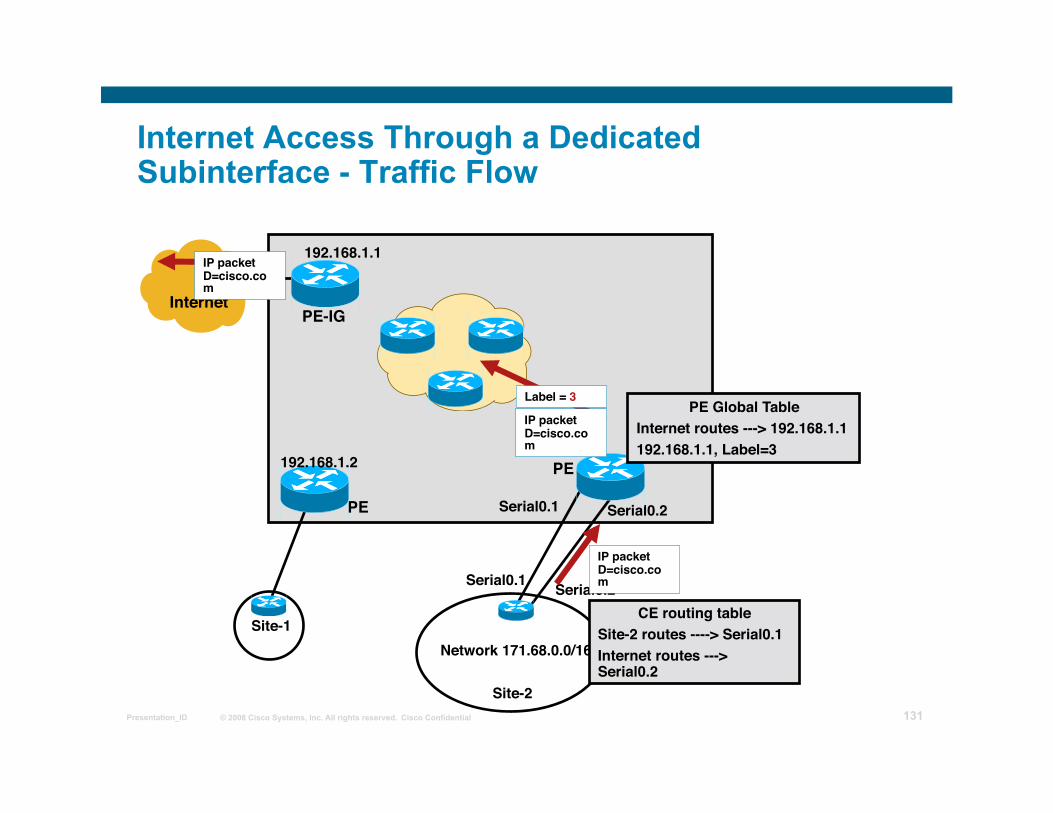
Internet Access Through a Dedicated Subinterface - Traffic Flow
PE
PE
Internet
Site-1
PE-IG
Site-2
Network 171.68.0.0/16
Serial0.1
192.168.1.1
192.168.1.2
Serial0.2
Serial0.1 Serial0.2 CE routing table
Site-2 routes ----> Serial0.1 Internet routes ---> Serial0.2
IP packetD=cisco.com
PE Global Table Internet routes ---> 192.168.1.1 192.168.1.1, Label=3
Label = 3
IP packetD=cisco.com
IP packetD=cisco.com
© 2008 Cisco Systems, Inc. All rights reserved. Cisco Confidential Presentation_ID 132
Limitations of Separate Internet Access
Drawbacks: Requires separate physical link or specific WAN
encapsulation PE routers must be able to perform Internet routing (and
potentially carry full Internet routing) Wholesale Internet access or Central Firewall service
cannot be implemented with this model PE router has internet as well as VPN routes. A lot of
ISPs do not like this idea due to security reasons
Benefits: Well-known model Supports all customer requirements Allows all Internet services implementation, including a
BGP session with the customer
© 2008 Cisco Systems, Inc. All rights reserved. Cisco Confidential Presentation_ID 133
Internet Access Backbone as a Separate VPN
© 2008 Cisco Systems, Inc. All rights reserved. Cisco Confidential Presentation_ID 134
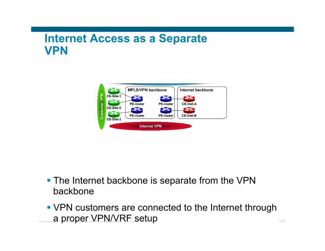
Internet Access As a Separate VPN
This design realizes Internet access by using MPLS VPN features:
An Internet gateway is connected as a CE router to the MPLS VPN backbone
An Internet gateway shall not insert full Internet routing into the VPN; only the default route and the local (regional) routes can be inserted
Every customer that needs Internet access is assigned to the same VPN as the Internet gateway
© 2008 Cisco Systems, Inc. All rights reserved. Cisco Confidential Presentation_ID 135
Internet Access as a Separate VPN
The Internet backbone is separate from the VPN backbone
VPN customers are connected to the Internet through a proper VPN/VRF setup

© 2008 Cisco Systems, Inc. All rights reserved. Cisco Confidential Presentation_ID 136
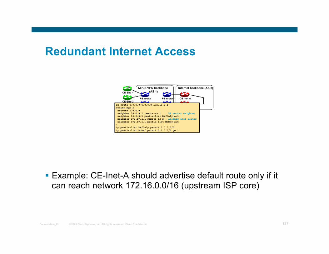
Redundant Internet Access
Multiple CE-Internet routers can be used for redundancy All CE-Internet routers advertise default route
Internet VPN will recover from CE-Internet router failure Preferred default route can be indicated via MED attribute
Default route should be advertised conditionally to achieve higher resilience
© 2008 Cisco Systems, Inc. All rights reserved. Cisco Confidential Presentation_ID 137
Redundant Internet Access
Example: CE-Inet-A should advertise default route only if it can reach network 172.16.0.0/16 (upstream ISP core)
© 2008 Cisco Systems, Inc. All rights reserved. Cisco Confidential Presentation_ID 138
Limitations of Running an Internet Backbone in a VPN
Drawbacks: Full Internet routing cannot be carried in the VPN; default
routes are needed that can lead to suboptimal routing Internet backbones act as CE routers to the VPN
backbone; implementing overlapping Internet + VPN backbones is tricky
Benefits: Supports all Internet access service types Can support all customer requirements, including a BGP
session with the customer, accomplished through advanced BGP setup
© 2008 Cisco Systems, Inc. All rights reserved. Cisco Confidential Presentation_ID 139
Internet Access using VRF Aware NAT
© 2008 Cisco Systems, Inc. All rights reserved. Cisco Confidential Presentation_ID 140
Internet Access using VRF-aware NAT
• If the VPN customers need Internet access without internet routes, then VRF-aware NAT can be used at the Internet-GW i.e. ASBR
• The Internet GW doesn’t need to have internet routes either
• Overlapping VPN addresses is not a problem
© 2008 Cisco Systems, Inc. All rights reserved. Cisco Confidential Presentation_ID 141
Internet Access using VRF-aware NAT
• VPN customers could be using ‘overlapping’ IP address i.e. 10.0.0.0/8
• Such VPN customers must NAT their traffic before using either “extranet” or “internet” or any shared* services
• PE is capable of NATting the VPN packets (eliminating the need for an extra NAT device)
* VoIP, Hosted Content, Management etc/
© 2008 Cisco Systems, Inc. All rights reserved. Cisco Confidential Presentation_ID 142
Internet Access using VRF-aware NAT
Typically, inside interface(s) connect to private address space and outside interface connect to global address space
NAT occurs after routing for traffic from inside-to-outside interfaces
NAT occurs before routing for traffic from outside-to-inside interfaces
Each NAT entry is associated with the VRF
Works on VPN packets in the following switch paths : IP->IP, IP->MPLS and MPLS->IP
© 2008 Cisco Systems, Inc. All rights reserved. Cisco Confidential Presentation_ID 143
Internet
Internet Access using VRF-aware NAT PE11
PE-ASBR
MPLS Backbone
PE12
CE1
Blue VPN Site
10.1.1.0/24
P
CE2
10.1.1.0/24
Green VPN Site
ip nat inside
ip nat outside
217.34.42.2 .1
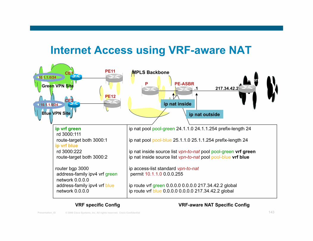
VRF-aware NAT Specific Config VRF specific Config
ip nat pool pool-green 24.1.1.0 24.1.1.254 prefix-length 24
ip nat pool pool-blue 25.1.1.0 25.1.1.254 prefix-length 24
ip nat inside source list vpn-to-nat pool pool-green vrf green ip nat inside source list vpn-to-nat pool pool-blue vrf blue
ip access-list standard vpn-to-nat permit 10.1.1.0 0.0.0.255
ip route vrf green 0.0.0.0 0.0.0.0 217.34.42.2 global ip route vrf blue 0.0.0.0 0.0.0.0 217.34.42.2 global
ip vrf green rd 3000:111 route-target both 3000:1 ip vrf blue rd 3000:222 route-target both 3000:2
router bgp 3000 address-family ipv4 vrf green network 0.0.0.0 address-family ipv4 vrf blue network 0.0.0.0
© 2008 Cisco Systems, Inc. All rights reserved. Cisco Confidential Presentation_ID 144
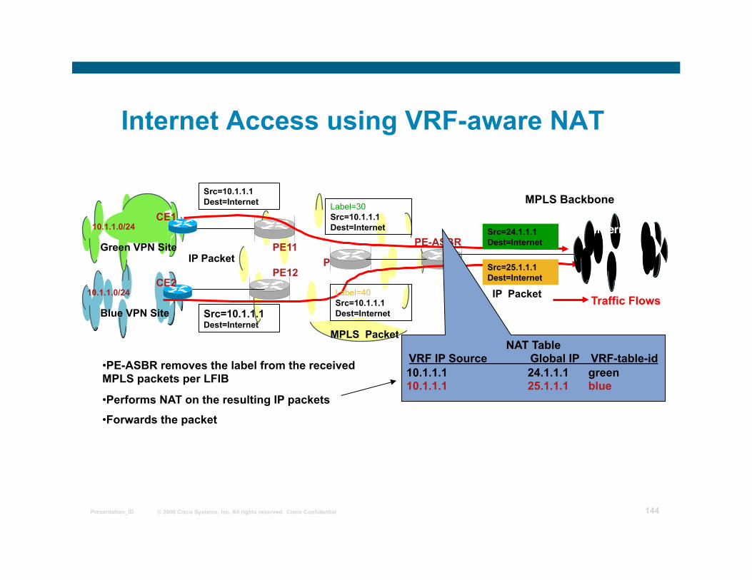
Internet Access using VRF-aware NAT
PE11 PE-ASBR
MPLS Backbone
PE12
CE1
Blue VPN Site
10.1.1.0/24
P
CE2
Traffic Flows
10.1.1.0/24
Green VPN Site
Src=10.1.1.1 Dest=Internet
Src=24.1.1.1 Dest=Internet
Src=25.1.1.1 Dest=Internet
Src=10.1.1.1 Dest=Internet
Label=30 Src=10.1.1.1 Dest=Internet
Label=40 Src=10.1.1.1 Dest=Internet
IP Packet
MPLS Packet
IP Packet
NAT Table VRF IP Source Global IP VRF-table-id 10.1.1.1 24.1.1.1 green 10.1.1.1 25.1.1.1 blue
• PE-ASBR removes the label from the received MPLS packets per LFIB
• Performs NAT on the resulting IP packets
• Forwards the packet
Internet
© 2008 Cisco Systems, Inc. All rights reserved. Cisco Confidential Presentation_ID 145


![[MPLS Configuration Guide] - D-Link Academyacademy.dlink.com/temp/exam_Issue/230/MPLS Configuration Guide… · MPLS Configuration Guide Multiprotocol Label Switching (MPLS) MPLS](https://img.pdfslide.us/doc/110x75/5a815ac47f8b9ada388cfeea/mpls-configuration-guide-d-link-configuration-guidempls-configuration-guide.jpg)