Embed Size (px)
Citation preview
Designs & Material Solutions
Date: 17 & 18 December 2014
Sanitation Solutions for Flood Prone and High Table Water
Areas
FINAL REPORT SANTE BRAC PROJECT
COUNTRY: BANGLADESH
Prepared by: Groover Mamani, Mariska Rontetap, Stan Maessen
Bangladesh Partners:
Indian Partners: Finish Society, Solutions, Shah
Dutch Partners:

Table of Contents
1 Introduction ................................................................................................................................................. 1
1.1 Background ......................................................................................................................................... 1
1.2 Project objectives ................................................................................................................................ 1
1.3 Project set-up ...................................................................................................................................... 1
1.3.1 Actual project flow during the carry-out phase of the project .......................................................... 3
1.3.2 Project deliverables ......................................................................................................................... 3
1.4 Project evaluation................................................................................................................................ 3
1.4.1 Contest ............................................................................................................................................ 3
1.4.2 Cooperation between the partners within the project ......................................................................4
1.5 Future recommendations ................................................................................................................... 6
1.5.1 Designs versus costs ....................................................................................................................... 6
1.5.2 Designs versus environment and climate issues ............................................................................... 7
1.5.3 General conclusions ......................................................................................................................... 7
2 Designs ....................................................................................................................................................... 9
2.1 Most used designs in Bangladesh ....................................................................................................... 9
2.1.1 Water-flows in pits ......................................................................................................................... 10
2.2 Design criteria ................................................................................................................................... 11
2.2.1 Overview of the criteria ................................................................................................................. 11
2.3 Modified Urine Diversion Toilet, forced dehydration ......................................................................... 12
2.3.1 Description of the concept/system: ............................................................................................... 12
2.3.2 Bill of Quantities ............................................................................................................................ 15
2.3.3 Problem solving abilities ................................................................................................................ 15
2.3.4 Final conclusions ............................................................................................................................ 16
2.4 Offset seepage pit: Double Plastic Drum System ............................................................................... 18
2.4.1 Description system ........................................................................................................................ 18
2.4.2 Bill ................................................................................................................................................. 20
2.4.3 Problem solving abilities ................................................................................................................ 20
2.4.4 Final conclusions ............................................................................................................................ 21
2.5 Single Plastic Drum System ............................................................................................................... 22
2.5.1 Description system ........................................................................................................................ 22
2.5.2 Bill of quantities ............................................................................................................................. 24
2.5.3 Problem solving abilities ................................................................................................................ 24
2.5.4 Final conclusions ............................................................................................................................ 25
2.6 Single Offset Pit with Biogas System .................................................................................................26
2.6.1 Description system ........................................................................................................................26
2.6.2 Bills ................................................................................................................................................ 28
2.6.3 Problem solving abilities: ............................................................................................................... 28
2.6.4 Final conclusions ............................................................................................................................29
2.7 Step latrine (models 1 & 2) ................................................................................................................. 31
2.7.1 Introduction ................................................................................................................................... 31
2.7.2 Model 1 .......................................................................................................................................... 32
2.7.3 Model 2 ......................................................................................................................................... 33
2.7.4 Bill of Quantities ............................................................................................................................ 34
2.7.5 Problem solving abilities ................................................................................................................ 34
2.7.6 Final conclusions ............................................................................................................................ 35
3 Alternative Materials .................................................................................................................................. 37
3.1 Use of BRCC ...................................................................................................................................... 37
3.2 Use of Ferro Cement .......................................................................................................................... 38
3.3 Use of Sand Envelopes ...................................................................................................................... 38
3.3.1 Basic Design Principles .................................................................................................................. 39
3.3.2 Health Aspects .............................................................................................................................. 39
4 WASTEs Options ........................................................................................................................................ 41
4.1 Floating toilets .................................................................................................................................. 41
4.2 BoP Potti: In-house Toilets ................................................................................................................ 42
4.3 Rottebehalter .................................................................................................................................... 43
5 Monitoring of Designs ................................................................................................................................ 47
6 Conclusions & Recommendations .............................................................................................................. 47
7 Combining designs ..................................................................................................................................... 47
8 Way Forward ..............................................................................................................................................49
9 Annexes ..................................................................................................................................................... 51
ANNEX 1: OTHER NOT SELECTED DESIGNS .................................................................................................... 52
ANNEX 2: Context challenges and issues with existing designs .........................................................................60
ANNEX 3: DESIGN CRITERIA ............................................................................................................................. 61
ANNEX 5: INFORMATION ABOUT BIOGAS ......................................................................................................64
BIOGAS .........................................................................................................................................................64
BIOGAS DIGESTERS ......................................................................................................................................64
BIOGAS FORMATION .................................................................................................................................... 65
ANNEX 6: CALCULATION OF VOLUMES .......................................................................................................... 67
ANNEX 7: EARTHEN MOUND ........................................................................................................................... 74

ANNEX 8: ALTERNATIVE DESIGNs ................................................................................................................... 76
ANNEX 9: Formulas for Calculation urine evaporation in a vessel ...................................................................... 84
Used formulas: ............................................................................................................................................... 84
Calculation evaporation*** ................................................................................................................................. 85
ANNEX 10: Matrix ..............................................................................................................................................86
Page | 1
1 Introduction
1.1 Background
Compared to many other developing countries, the official sanitation coverage in Bangladesh is relatively good.
In Southern Asia, only 34% population has access to improved sanitation facilities (United Nations, 2010),
whereas in Bangladesh 55% of the urban and 52% of the rural people is connected (JMP, 2010). The most
common form of sanitation is pit latrines: 42% of the urban and 70% of the rural population uses pit latrines
(JMP, 2010). The locally available materials, high affordability and easiness to install all contribute to the pit
latrine’s popularity. Yet, pit latrines also come with drawbacks. As Bangladesh generally has a high
groundwater table and most rural people use groundwater as drinking water source, water source pollution
occurs, leading to sickness and death due to diarrheal diseases. Moreover, as the pits fill up with groundwater or
rainwater (after floods), the pits and therefore the toilets become unusable. This project aimed at tackling the
sanitation approach in different areas in Bangladesh, each suffering from different natural challenges: high
groundwater tables, highly prone to flooding, rocky soils. By involving local counterparts and their network of
small enterprises, the sub-goal was to enhance local entrepreneurs in their endeavours to be part of a
sustainable sanitation chain, thereby making sustainable sanitation reachable for a large number of households
in Bangladesh. The idea of this project was to use existing concepts and have them adjusted to the Bangladeshi
situation with respect to: 1) hydro-geographical challenges (flood area; rocky soils; high groundwater tables); 2)
social acceptance; and 3) the availability of materials. Some materials used in standard designs may be too
expensive or not available locally, making an adaptation to the Bangladeshi situation necessary for any
sanitation solution to be sustainable.
1.2 Project objectives
The project aimed to achieve 3 different results:
1. Safe sanitation solutions identified with involvement of entrepreneurs;
2. Innovative safe sanitation solutions identified and disseminated through a contest;
3. Safe sanitation solutions disseminated among a wide audience.
1.3 Project set-up
The project was aimed to flow through the following steps:
Result 1: Safe sanitation solutions identified with involvement of entrepreneurs
1.1: Organisation of kick-off meeting with local partners
1.2: Formation of focal groups and draft of baseline assessment
1.3: To organize a brainstorm on national and regional level with international experts / partners, local
partners and entrepreneurs for identification of innovative sanitation solutions. Various international
experiences and disciplines will be considered.
1.4: Piloting innovations by entrepreneurs
1.5: Drafting a report with innovative solutions, video links and recommendations for follow-up
Page | 2
Result 2: Innovative safe sanitation solutions identified and disseminated through a contest
2.1: Organization of contest for the identification safe sanitation solutions
2.2: Piloting winning sanitation solutions in all regions
2.3: Sharing of pilot results on national level and fine-tuning of sanitation solutions on regional level
Result 3: Safe sanitation solutions disseminated among a wide audience
3.1: International presentation of the project during World Toilet Day (19 November 2013), announcing
contest winners at World Water Day (22 March 2014) and during World Water Week (2014) in
Stockholm
3.2: Development and dissemination of manuals, guidelines and videos in Bangla and English to
relevant stakeholders (nationally and internationally)
3.3 Final Workshop in co-operation with related IRC Action Researches
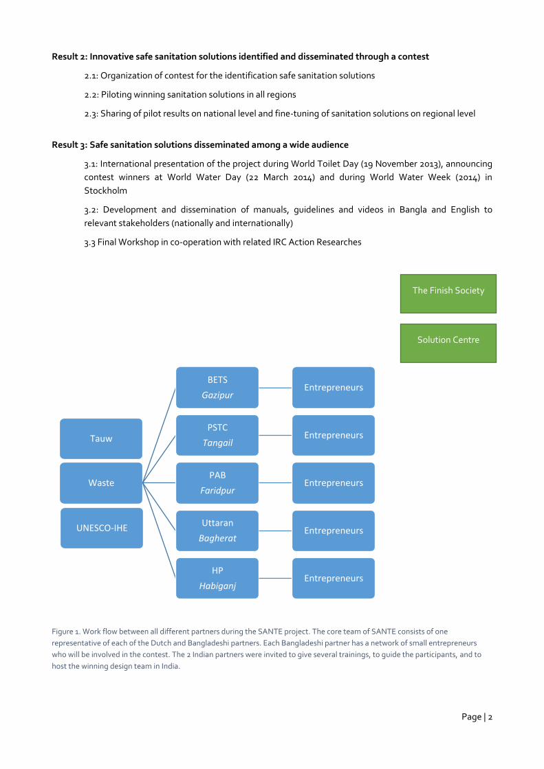
Figure 1. Work flow between all different partners during the SANTE project. The core team of SANTE consists of one
representative of each of the Dutch and Bangladeshi partners. Each Bangladeshi partner has a network of small entrepreneurs
who will be involved in the contest. The 2 Indian partners were invited to give several trainings, to guide the participants, and to
host the winning design team in India.
UNESCO-IHE
Tauw
Waste
BETS
Gazipur Entrepreneurs
PSTC
Tangail Entrepreneurs
PAB
Faridpur Entrepreneurs
Uttaran
Bagherat Entrepreneurs
HP
Habiganj Entrepreneurs
The Finish Society
Solution Centre
Page | 3
1.3.1 Actual project flow during the carry-out phase of the project
The project kick-off took place in September 2013 with an inception workshop in Bangladesh. All partners were
represented, as well as IRC and BRAC. The workshop lasted one day, after which we spread out to the different
project areas. In the period of October – November 2013, business baselines were carried out. Then the project
had to be put on hold for a few months due to political turmoil in Bangladesh. From February 2014, the trainings
started, the first designs started to come in, and the project website was created
(http://santebangladesh.wikispaces.com/).
A second workshop was held in June 2014. Designs were improved, and the progress so far was discussed (see
Challenges). In the period from August to November, the designs were constructed and tested in the field.
September/October: it became clear that the project was not tax exempted and as a consequence the budget
decreased with 21%. Agreed was that the burden of the reduction would be covered by the Dutch partners. In
December a final workshop took place with BRAC and partners.
1.3.2 Project deliverables
The agreed upon deliverables of the project, after revision of the approach (see also 1.4.1) were the following:
September 2013: workshop report
November 2013: baseline reports
January 2014: Manual alternative designs and technologies (by Jan Spit)
May 2014: training reports
June 2014: first designs and comments + Learning Guide Part B in Bangladesh
August 2014: Set of design criteria
December 2014: Final workshop; designs plus final report
1.4 Project evaluation
Internally we evaluated the project on several criteria:
The idea of a contest
The cooperation between the partners within the project
The cooperation with other awardees of related projects
Outcomes of the project, i.e. usefulness of the final designs
1.4.1 Contest
The project approach was based on the following main assumptions: `
1) Local small businesses are capable of developing technical designs, and
2) Local organisations are capable of training and supporting small and medium entrepreneurs in the
design process.
When developing the project proposal it was assumed that the local small entrepreneurs would be able or were
made able with support of the partners to develop new innovative designs. The whole idea of the contest was
based on this assumption. The trainings provided by the Indian partners should have provided the basis for such
initiatives by the entrepreneurs.
Page | 4
This assumption proved to be too optimistic. The learnings provided by the trainings of the partners proved not
to be the catalysts for innovation. As a result, the Bangladesh project partners took over the development of
the designs. They mostly based their innovations on what had been provided by the Indian partners.
Originally, the setup of the program was as such that each Bangladesh partner would be linked to one thematic
partner: Practical Action to Tauw Bv, PSTC to P.K. Jha, Uttaran to the Finish Society and HP to The Solutions
Centre. It was the intention that the Bangladesh partners would identify small and medium entrepreneurs and
that each thematic partner would provide training to their respective Bangladesh partner and its selected
entrepreneurs. This also worked out that way: the entrepreneurs were selected (based on a baseline) and the
trainings provided. The provided technologies and alternatives where well received but did not serve as catalyst
for further development of more context oriented new designs. The reason was twofold: the Bangladesh
partners either did not understand (in time) what was expected from them (support the entrepreneurs with
developing new designs and alternatives) and the Bangladesh organisations –except practical Action- where
not capable of initiating a full-fledged design process together with the entrepreneurs. Instead, they started
hiring engineers and developing the designs themselves. Most of the “new” designs became a copy of the
designs provided by the Indian partners. Discussion in June between the partners and WASTE in Dhaka revealed
that the Bangladesh partners had not understood the concept of the program. By then the program had
progressed to a level that the original idea of organising a contest between the different entrepreneurs was no
longer feasible.
Together with IRC it was decided to focus on the designs itself and the testing rather than on the contest. The
remaining budgets of the thematic partners would be utilized not only for its designated Bangladesh partner
but for all. In the discussions in Dhaka it was brought forward that trainings given to one particular partner
would have been also of interest for others, which was acknowledged and taken up in the changes in the project
approach.
1.4.2 Cooperation between the partners within the project
1.4.2.1 Communication issues
In general the atmosphere between the different project partners was very good. WASTE has a long track
record with the Indian partners as well as with some of the Bangladeshi partners. With UNESCO-IHE most of
the previous cooperation were around capacity building, this was one of the first joints projects on research.
Even after several drawbacks and difficult moments, the cooperation between most partners stayed strong and
positive, and the partners will continue to work together after the closure of the project.
Page | 5
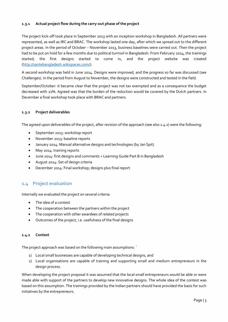
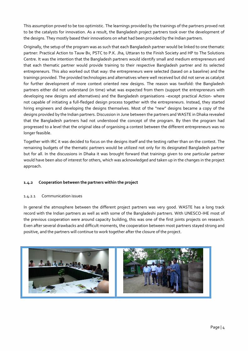
Figure 2. Some impressions of the kick-off meeting held in September 2013 in Dhaka and the target areas.
The relation between WASTE and IRC/BRAC was not optimal at the beginning of 2014. Reason for this was the
lack of reporting to IRC/BRAC which should have been done once a month. It took several months (almost half a
year) and lots of initiative from both sides (e.g. weekly skype reporting meetings, etc.) to normalize the
situation and restore the balance between the Dutch parties.
Even more importantly, at the beginning of 2014 the communication between WASTE and the Bangladesh
partners was not very good and also here weekly skypes were initiated to get communication ongoing. Only
during the mission in June 2014 the Bangladesh partners revealed that they had not understood the project
principles and that they were not instructed how to go about during the start-up workshop in September 2013.
Asked directly about the involvement of the entrepreneurs they explained that according to them they had to
develop the designs and not the entrepreneurs. “The contest was to be held amongst themselves”.
Having to put so much attention to the communication between the Dutch and the Bangladesh partners, the
communication between WASTE and the Indian partners became a bit less.
Communication between BETS and the project was difficult. BETS was approached several times by the
Bangladesh and the Dutch Partners but BETS only rarely replied. During the meetings in June 2014 it was
agreed that Practical Action would take over the role of BETS, which they did together with PSTC.
1.4.2.2 Overall management
The overall management of the program by WASTE was handed over to from Valentin Post to Stan Maessen in
the beginning of 2014. After a prolonged period of idleness (due to political turmoil in Bangladesh), the program
restarted in January. The delays were aggravated by the change in management.
Main decisions & change in the approach (June 2014):
Final results: the aim is for 2 or 3 good, safe, locally applicable designs
Revision of project plan and time table
No contest approach, but rather a joint focus on testing of designs
Rather than a fixed partnering of consultants, support is to be provided by the best matching
consultant, based on actual need of Bangladesh partner
Designing to be done by all partners, not solely local entrepreneurs.
The changes were proposed in June and confirmed by IRC in skype meetings in August and September 2014.
1.4.2.3 Cooperation with other awardees of related projects
When looking at other project awardees it became clear that there could be a good synergy with some of the
other projects – particular in the field of faecal sludge management. Contact was sought with the consortium
dealing with faecal sludge (members of the VeSV project: University of Leeds with Bangladesh University of
Page | 6
Engineering and Technology BUET, NGO Forum for Public Health, Bangladesh, and IWMI International Water
Management Institute, Sri Lanka). Although there was an interest with both parties for information exchange,
there proved to be too little time for this. Hence, it was agreed to leave it to BRAC and IRC to further integrate
the outcomes of the projects. It was clear to both parties that toilet systems and FSM need to be part of 1
integrated system.
1.5 Future recommendations
Comments concerning technologies and materials:
1.5.1 Designs versus costs
The costs for commonly used toilet facilities in Bangladesh are low to very low compared to other countries like
India and Nepal). The low costing however, also immediately translates into using very low quality construction
materials and subsequent low quality structures which did not at all qualify for durable, robust and safe
structures. For instance, the partners did some investigation in the cement rings which cost only up to 2 to 3
euro per ring. The quality of these rings, is extremely bad and corrode rapidly. Pits constructed with these rings
collapse regularly and are not watertight at all.
When considering structural improvements as to prevent the problems as described under chapter 2a (see table
below), it means investing in better quality construction materials. Unlike labour cost, good quality building
materials come will higher cost. This is reflected in the BoQ’s of almost all proposed designs.
The partners included materials which are probably not that durable (polyethylene sheets, etc.), but which are
cheap. Low cost should be assessed against durability. All materials had to be available on the local market.
Problem analysis conventional toilets in Bangladesh:
1. High fill-up rate due to infiltration of groundwater into the pit, causing pre-mature need for emptying or
even building a new toilet. Considering that emptying services in Bangladesh are scarce or not existing
often perfectly good toilets are abandoned and replaced by a new one.
2. Groundwater pollution due to seepage of wastewater from the pit to the groundwater. Depending on
the soil type seepage water (black water) from pits can flow much larger distances than is generally
expected and causes pollution of potable groundwater.
3. Sub-structure damage due to water level fluctuation in the pit, damaging its walls. Fluctuating water
levels in and around the pits creates constant changing pressure on the structures and changing water
flows through the structures. Both cause corrosions and collapse.
4. Surface water bodies pollution due to wastewater overflow when groundwater level rises
5. Saline conditions: Saline conditions cause damaged slabs and collapsing pits due to corrosion of
brickwork and cement
Besides different (more costly) materials, the partners also experimented with different new or known materials
like bamboo reinforced concrete and ferro-cement as to reduce costs. The bamboo reinforced concrete needs
more research to assess whether it is indeed a cheaper substitute of steel reinforced concrete. The conclusion of
the partners was that the savings made by using cheaper bamboo instead of steel where evened out because
more concrete (cement) had to be used to ensure proper coverage of the bamboo. The thickness of the bamboo
is a topic of further research.
Using ferro-cement as cheaper alternative for regular RCC structures is a proven concept and much information
and experiences are available. But ferro-cement structures need qualified entrepreneurs who are not readily
available in Bangladesh.
Page | 7
The partners also experimented with older concepts like mounds and sand envelopes. The mounds are primarily
used for preventing pits to be filled with either ground water or floods. It is an old concept which is being used
all over the world. A mound can be erected by the people themselves and does not require craftsmanship. The
sand envelope is a simple technology used to create biological condition around seepage pits which cleans the
sewage water while seeping through the envelope. The envelopes are quite efficient. Both solutions are not
very expensive and can be built by the households themselves as own contribution.
Conclusion: It is reasonable to state that toilets which qualify as robust, durable and safe require qualitatively
better materials which will make the cost for the toilets significant higher than the cost for the ordinary used
toilets.
Conclusion: additional relatively cheap measures can be taken which improve the chances of pollution of the
direct living environment.
1.5.2 Designs versus environment and climate issues
Most of the partners focussed on designs which fulfil the requirements concerning problems like collapse during
monsoon, possibility of ground water pollution and overflow of pits during floods. These solutions are available,
but they come at a cost (see remarks above about the materials).
However, there are some critical remarks about the technologies that have been proposed. All designs are on-
site solutions (isolated instead as part of a comprehensive sanitation system), most designs focus on increasing
a lifetime of the pits without emptying, but with releasing potential pollutants into the direct environment and
all systems require eventually some kind of pit emptying. And pit emptying is usually expensive.
Old sludge from pits is difficult to digest and drying is the most commonly and cheapest way of treatment.
Given the climatic conditions of Bangladesh (prolonged monsoon periods and high humidity levels) reduce the
periods where sludge can dry properly.
Desludging and sludge management is most probably a bigger challenge than constructing toilets that can
resist the climatic conditions of Bangladesh.
From this perspective the following toilet solutions are considered the most promising:
1. The UDDT, liquid forced dehydration toilet, because it reduces the liquid faction and will allow the
reuse of dried sludge (which is easy). We are still looking at possibilities to reduce the investment costs
2. The BoP Potti because it has a very low investment cost (40us) plus collection system (higher opex: no
research done, proposal is under preparation). Great possibilities for income generation for the service
providers
Note: the Bangladesh partners were not completely convinced that an in-house toilet would be socially
acceptable.
1.5.3 General conclusions
1. Entrepreneurs in Bangladesh are conceptually not capable of developing/designing new alternative
toilet options. Real engineering support is needed.
2. Of 15 developed designs 5 were selected as being fulfilling the criteria.
3. Qualitative acceptable construction materials needed to fulfil the requirement and criteria and come at
a cost. Toilets fulfilling the criteria are significantly more expensive than the conventional models.
4. More research is needed to assess the usability of alternative materials like bamboo reinforced
concrete.

Page | 8
5. Promotion of the use of proven concepts like ferro-cement, mounds and sand envelopes needs to be
enhanced and brought under the attention of a wider audience (NGO’s, entrepreneurs etc.)
6. More social research (acceptance) is needed to engage in in-house solutions (low investment costs)
which are integrated part of a comprehensive sanitation system which includes regular collection
(because it is regular also cheaper, like solid waste collection), processing and reuse/disposal.
Page | 9
2 Designs
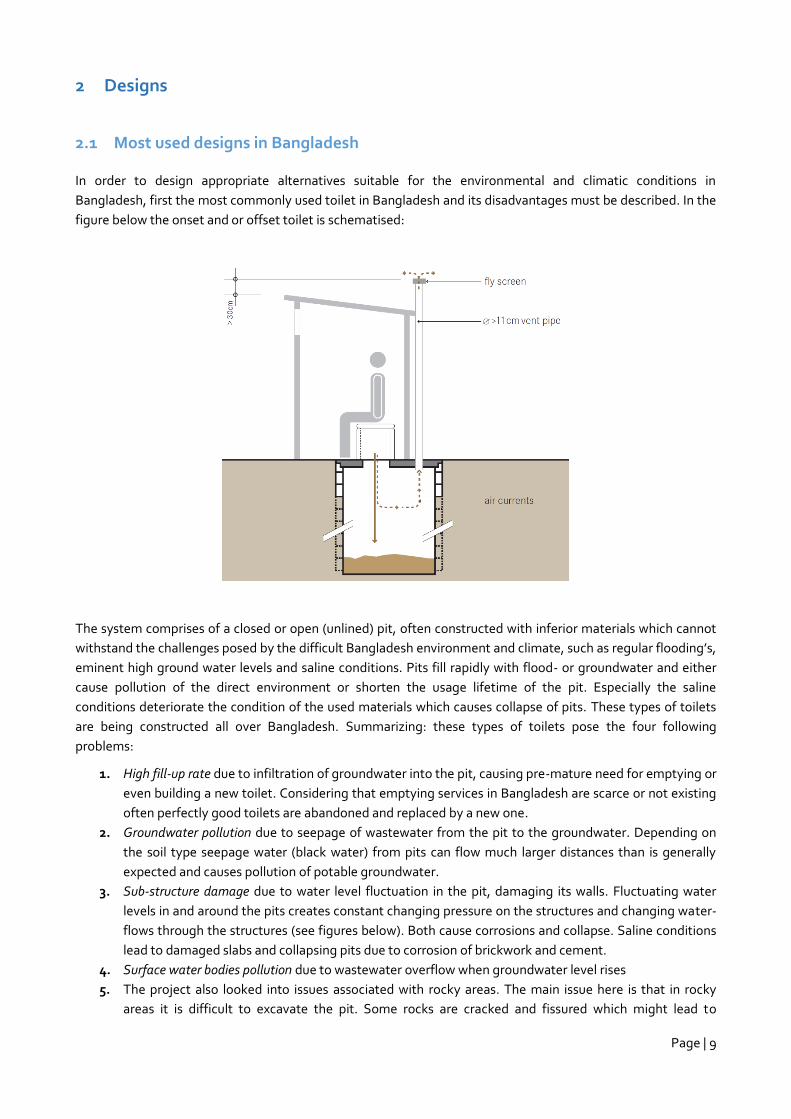
2.1 Most used designs in Bangladesh
In order to design appropriate alternatives suitable for the environmental and climatic conditions in
Bangladesh, first the most commonly used toilet in Bangladesh and its disadvantages must be described. In the
figure below the onset and or offset toilet is schematised:
The system comprises of a closed or open (unlined) pit, often constructed with inferior materials which cannot
withstand the challenges posed by the difficult Bangladesh environment and climate, such as regular flooding’s,
eminent high ground water levels and saline conditions. Pits fill rapidly with flood- or groundwater and either
cause pollution of the direct environment or shorten the usage lifetime of the pit. Especially the saline
conditions deteriorate the condition of the used materials which causes collapse of pits. These types of toilets
are being constructed all over Bangladesh. Summarizing: these types of toilets pose the four following
problems:
1. High fill-up rate due to infiltration of groundwater into the pit, causing pre-mature need for emptying or
even building a new toilet. Considering that emptying services in Bangladesh are scarce or not existing
often perfectly good toilets are abandoned and replaced by a new one.
2. Groundwater pollution due to seepage of wastewater from the pit to the groundwater. Depending on
the soil type seepage water (black water) from pits can flow much larger distances than is generally
expected and causes pollution of potable groundwater.
3. Sub-structure damage due to water level fluctuation in the pit, damaging its walls. Fluctuating water
levels in and around the pits creates constant changing pressure on the structures and changing water-
flows through the structures (see figures below). Both cause corrosions and collapse. Saline conditions
lead to damaged slabs and collapsing pits due to corrosion of brickwork and cement.
4. Surface water bodies pollution due to wastewater overflow when groundwater level rises
5. The project also looked into issues associated with rocky areas. The main issue here is that in rocky
areas it is difficult to excavate the pit. Some rocks are cracked and fissured which might lead to
Page | 10
pollution of groundwater. Rock type and rock weathering conditions, determine to a large extend the
possibility of digging pits for toilets and potential pollution. Hard unfractured rock types like granite are
apparently rare according to our partners and in most ‘rocky areas’ (read hilly areas) it is in general not
difficult to dig pits. Therefore we translated our assignment “rocky areas” into: “when it is impossible to
use a pit”.
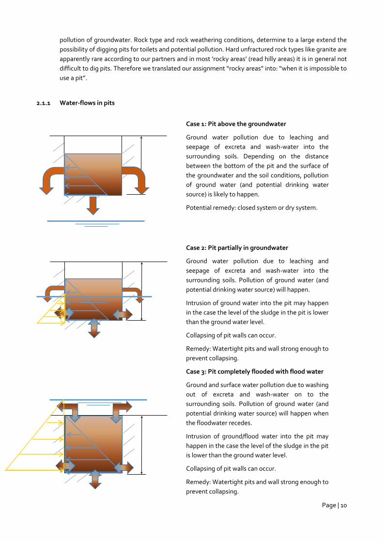
2.1.1 Water-flows in pits
Case 1: Pit above the groundwater
Ground water pollution due to leaching and
seepage of excreta and wash-water into the
surrounding soils. Depending on the distance
between the bottom of the pit and the surface of
the groundwater and the soil conditions, pollution
of ground water (and potential drinking water
source) is likely to happen.
Potential remedy: closed system or dry system.
Case 2: Pit partially in groundwater
Ground water pollution due to leaching and
seepage of excreta and wash-water into the
surrounding soils. Pollution of ground water (and
potential drinking water source) will happen.
Intrusion of ground water into the pit may happen
in the case the level of the sludge in the pit is lower
than the ground water level.
Collapsing of pit walls can occur.
Remedy: Watertight pits and wall strong enough to
prevent collapsing.
Case 3: Pit completely flooded with flood water
Ground and surface water pollution due to washing
out of excreta and wash-water on to the
surrounding soils. Pollution of ground water (and
potential drinking water source) will happen when
the floodwater recedes.
Intrusion of ground/flood water into the pit may
happen in the case the level of the sludge in the pit
is lower than the ground water level.
Collapsing of pit walls can occur.
Remedy: Watertight pits and wall strong enough to
prevent collapsing.
Page | 11
The partners tried to remediate the 4 above mentioned issues using existing and new concepts.
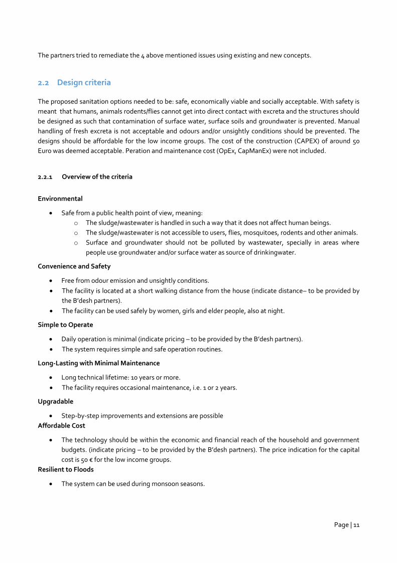
2.2 Design criteria
The proposed sanitation options needed to be: safe, economically viable and socially acceptable. With safety is
meant that humans, animals rodents/flies cannot get into direct contact with excreta and the structures should
be designed as such that contamination of surface water, surface soils and groundwater is prevented. Manual
handling of fresh excreta is not acceptable and odours and/or unsightly conditions should be prevented. The
designs should be affordable for the low income groups. The cost of the construction (CAPEX) of around 50
Euro was deemed acceptable. Peration and maintenance cost (OpEx, CapManEx) were not included.
2.2.1 Overview of the criteria
Environmental
Safe from a public health point of view, meaning:
o The sludge/wastewater is handled in such a way that it does not affect human beings.
o The sludge/wastewater is not accessible to users, flies, mosquitoes, rodents and other animals.
o Surface and groundwater should not be polluted by wastewater, specially in areas where
people use groundwater and/or surface water as source of drinkingwater.
Convenience and Safety
Free from odour emission and unsightly conditions.
The facility is located at a short walking distance from the house (indicate distance– to be provided by
the B’desh partners).
The facility can be used safely by women, girls and elder people, also at night.
Simple to Operate
Daily operation is minimal (indicate pricing – to be provided by the B’desh partners).
The system requires simple and safe operation routines.
Long-Lasting with Minimal Maintenance
Long technical lifetime: 10 years or more.
The facility requires occasional maintenance, i.e. 1 or 2 years.
Upgradable
Step-by-step improvements and extensions are possible
Affordable Cost
The technology should be within the economic and financial reach of the household and government
budgets. (indicate pricing – to be provided by the B’desh partners). The price indication for the capital
cost is 50 € for the low income groups.
Resilient to Floods
The system can be used during monsoon seasons.
Page | 12
Faecal Sludge Collection and Treatment
The system should consider a faecal sludge collection and treatment system, in such a way that it can
be disposed safely or re-used.
Technical Criteria (appropriate material use and robustness)
Preferible use of local materials and technology in the construction.
Robustness of construction (if undeground pit is proposed as substructure, it should be resistant to the
groudwater level fluctuations).
The design should be according to local building standards.
The system should include innovative solutions to avoid high fill-up rate due to infiltration of
groundwater into the pit.
Social Acceptability
The system should consider the socio-cultural practices and be accepted for the users.
Not all criteria proved to be always suitable in relation to the developed designs. His had a lot to do with the
concept behind the design. Similarly when making the selection of the final designs not all criteria were used as
mean to determine differences, because some of the criteria applied for all or none of the designs.
The selection matrix is presented in annex 4.
2.3 Modified Urine Diversion Toilet, forced dehydration
2.3.1 Description of the concept/system:
The system is designed to actively reduce the liquid component of excreta and wash-water by means of heat
radiation by the sun and forced aeration.
Both the liquid and the solid wastes are separated (by means of an urine diversion toilet bowl) and stored in
separate chambers. Both are immediately exposed to a flow of air that's driven through the chambers. The
movement of air is generated by the vent pipes with air being drawn into the chamber via the openings in the
toilet bowl. As the air moves through the system, it dehydrates the wastes similar to the regular urine diversion
toilet systems.
There are 4 factors important for evaporation in closed tanks: in order of importance: the air-humidity, the flow
of air, the ambient temperature and the hours of sunshine. The toilet system is designed to increase the
temperature inside the tank with help of the black celluloid polythene cover and stimulation of the airflow. The
sun heats up the black celluloid polythene cover, which again radiates heat into the evaporation chamber up to
temperatures of 60 oC (experiences of Enviro Loo, 2013). The other 2 factors cannot be influenced. On-site
experiences with similar forced dehydration in South Africa show that all daily intake of liquids evaporates. Also
the observations of Practical Action Bangladesh, who constructed a demonstration toilet confirm the
experiences of South Africa.
Page | 13
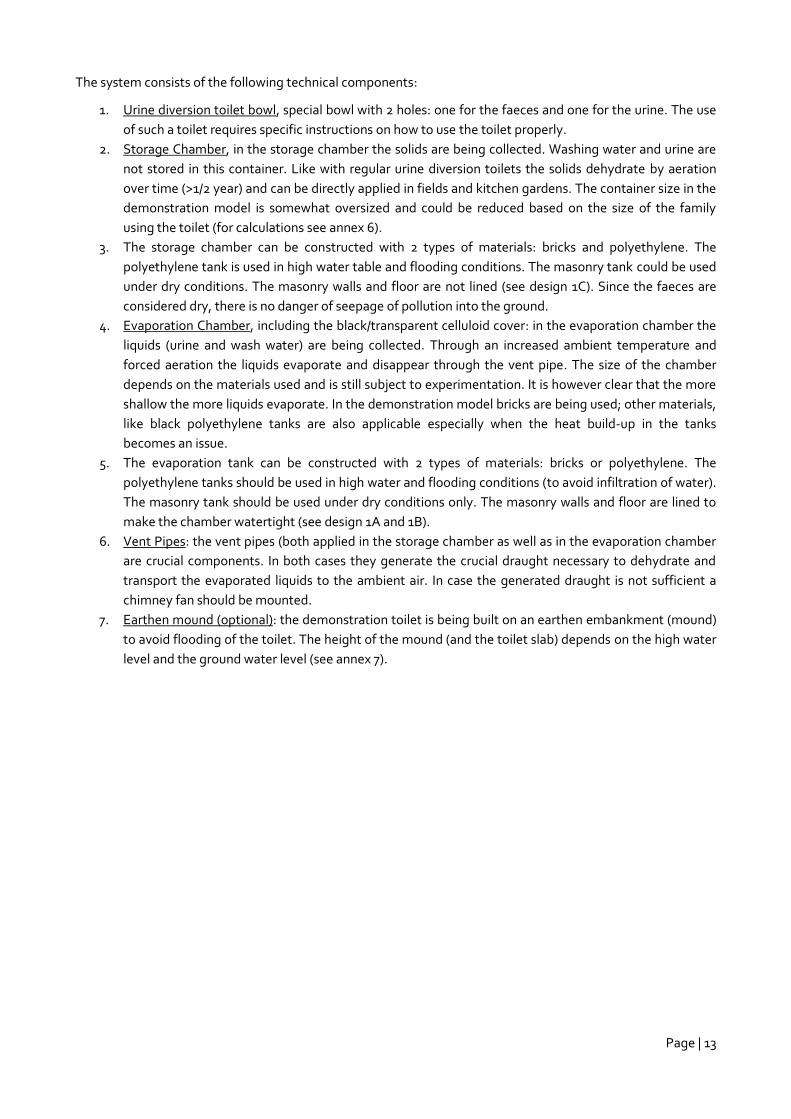
The system consists of the following technical components:
1. Urine diversion toilet bowl, special bowl with 2 holes: one for the faeces and one for the urine. The use
of such a toilet requires specific instructions on how to use the toilet properly.
2. Storage Chamber, in the storage chamber the solids are being collected. Washing water and urine are
not stored in this container. Like with regular urine diversion toilets the solids dehydrate by aeration
over time (>1/2 year) and can be directly applied in fields and kitchen gardens. The container size in the
demonstration model is somewhat oversized and could be reduced based on the size of the family
using the toilet (for calculations see annex 6).
3. The storage chamber can be constructed with 2 types of materials: bricks and polyethylene. The
polyethylene tank is used in high water table and flooding conditions. The masonry tank could be used
under dry conditions. The masonry walls and floor are not lined (see design 1C). Since the faeces are
considered dry, there is no danger of seepage of pollution into the ground.
4. Evaporation Chamber, including the black/transparent celluloid cover: in the evaporation chamber the
liquids (urine and wash water) are being collected. Through an increased ambient temperature and
forced aeration the liquids evaporate and disappear through the vent pipe. The size of the chamber
depends on the materials used and is still subject to experimentation. It is however clear that the more
shallow the more liquids evaporate. In the demonstration model bricks are being used; other materials,
like black polyethylene tanks are also applicable especially when the heat build-up in the tanks
becomes an issue.
5. The evaporation tank can be constructed with 2 types of materials: bricks or polyethylene. The
polyethylene tanks should be used in high water and flooding conditions (to avoid infiltration of water).
The masonry tank should be used under dry conditions only. The masonry walls and floor are lined to
make the chamber watertight (see design 1A and 1B).
6. Vent Pipes: the vent pipes (both applied in the storage chamber as well as in the evaporation chamber
are crucial components. In both cases they generate the crucial draught necessary to dehydrate and
transport the evaporated liquids to the ambient air. In case the generated draught is not sufficient a
chimney fan should be mounted.
7. Earthen mound (optional): the demonstration toilet is being built on an earthen embankment (mound)
to avoid flooding of the toilet. The height of the mound (and the toilet slab) depends on the high water
level and the ground water level (see annex 7).
Page | 14
Page | 15
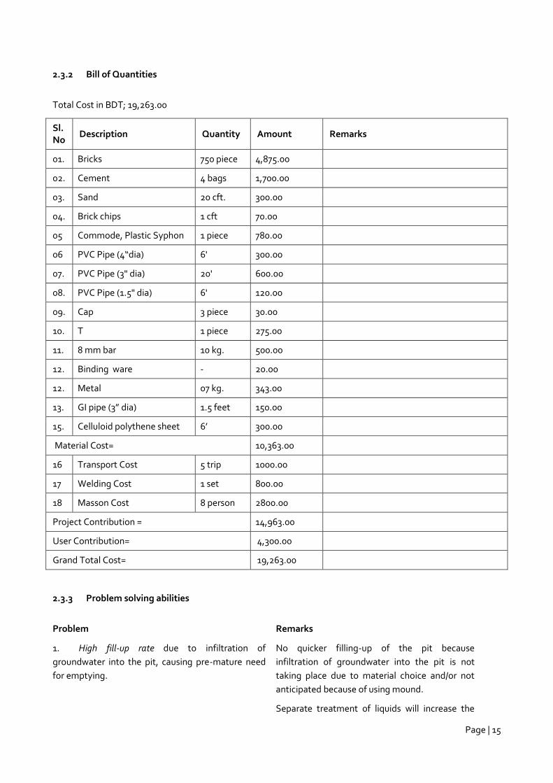
2.3.2 Bill of Quantities
Total Cost in BDT; 19,263.00
Sl. No
Description Quantity Amount Remarks
01. Bricks 750 piece 4,875.00
02. Cement 4 bags 1,700.00
03. Sand 20 cft. 300.00
04. Brick chips 1 cft 70.00
05 Commode, Plastic Syphon 1 piece 780.00
06 PVC Pipe (4“dia) 6' 300.00
07. PVC Pipe (3" dia) 20' 600.00
08. PVC Pipe (1.5" dia) 6' 120.00
09. Cap 3 piece 30.00
10. T 1 piece 275.00
11. 8 mm bar 10 kg. 500.00
12. Binding ware - 20.00
12. Metal 07 kg. 343.00
13. GI pipe (3” dia) 1.5 feet 150.00
15. Celluloid polythene sheet 6’ 300.00
Material Cost= 10,363.00
16 Transport Cost 5 trip 1000.00
17 Welding Cost 1 set 800.00
18 Masson Cost 8 person 2800.00
Project Contribution = 14,963.00
User Contribution= 4,300.00
Grand Total Cost= 19,263.00
2.3.3 Problem solving abilities
Problem Remarks
1. High fill-up rate due to infiltration of
groundwater into the pit, causing pre-mature need
for emptying.
No quicker filling-up of the pit because
infiltration of groundwater into the pit is not
taking place due to material choice and/or not
anticipated because of using mound.
Separate treatment of liquids will increase the
Page | 16
usage lifespan of the system.
2. Groundwater pollution due to seepage of
wastewater from the pit.
No seepage of waste water (pollution) from the
storage chamber is expected because the faeces
are considered dry and water in the faeces do not
seep pollutants.
3. Sub-structure damage due to water level
fluctuation in the pit, damaging its walls.
No fluctuation expected other than a gradual
rising of the solids and an occasional rise of
liquids when the toilet is used intensively (during
festivals). The materials used also prevent
collapsing.
4. Surface water bodies pollution due to
wastewater overflow when groundwater level rises.
Depending on the designs (and materials) used,
no chances of surface water bodies becoming
polluted.
Design Criteria Remarks
1. Simple to operate Daily operation is minimal. The system operates itself. The dimensions of
the storage chamber is sufficient for emptying once in max 2 years: (annual
accumulation of 450 lts/year dry sludge with a family of 5)
The system requires simple and safe operation routines. Once the storage
pit is filled it needs to be emptied manually with a shovel.
2. Acceptable costs
(acceptable is 50€)
The system is too expensive (202€) to be considered low-cost and the
technology should be re-designed to become affordable for low income
groups.
3. Innovativeness The system is never applied before in Bangladesh.
2.3.4 Final conclusions
Though the design meets most of the requirements and criteria, its costs are still too high to fit the final
qualification. Still the partners decided to keep this design as one of the options because of its innovativeness
and potential. Agreed was that Practical Action in collaboration with WASTE and possibly the other partners
continue to change/adjust the design and materials reducing the cost to an acceptable level and optimizing the
design. Marketing of this type of toilets will continue however, to meet also demand of other market segments
(mid- and high level income groups) in Bangladesh.
The demonstration model is equipped with only one storage chamber whereas 2 are optimally required. While
one storage chamber is in use, the other is closed to allow the faces to dry. After 6 month the chamber can be
opened and the dried faces used without danger.
The system allows reuse of (solid) wastes but is not considered the main objective. Reuse of the liquid faction
(urine and wash water) is not considered for the time being. Reuse of urine on large scale is difficult to organise.
Page | 17
In rural areas reuse of urine can be applied and other more regular UDDT designs are more applicable. This
design is made for densely populated areas where reuse of urine is no option (yet).
Different options (options 1B, 1C and 1D) with different material choices to accommodate different conditions
have been developed and are shown in annex 8 (no BoQ is provided).
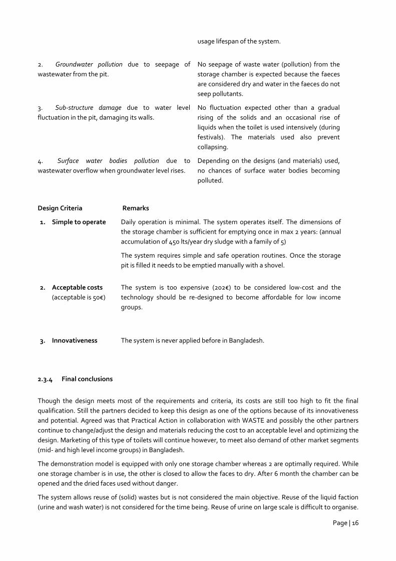
The calculations show that when only urine is collected in an evaporation chamber with an area of 1 m2, the
system will function without problems. When also the wash-water is collected in the evaporation chamber the
chamber needs to be extended to 2.5 m2, which is too large. An overflow system should be mounted in the
chamber.
The system is very promising, but needs further research and development to make it appropriate in
Bangladesh. Major research questions are related to the conditions in the evaporation chamber: velocity of the
draught, the actual temperature in the chamber and the subsequent evaporation levels. Another issue is the
choice of materials in relation to the efficiency of the evaporation.
Page | 18
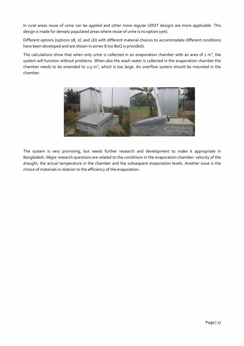
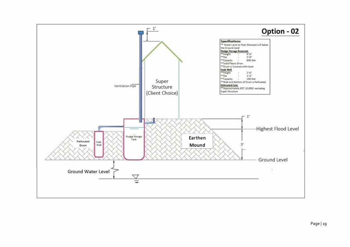
2.4 Offset seepage pit: Double Plastic Drum System
2.4.1 Description system
The main aim of this system is to increase the user-time of the storage chamber without having to empty it and
a controlled release of contaminants into the surroundings. This design is only applicable where there is no
danger for contamination of ground water.
The liquids are diverted into a seepage pit through an overflow. By using durable materials for the storage and
seepage chambers the system will not collapse during floods and high water occasions. The liquids however will
be released in the environment and the pollution of the direct surroundings needs to be contained. Mitigation
should be obtained by using a mound that can act as filter or a sand envelope to contain pollutants.
The system consists of the following technical components:
1. Storage Chamber: in the storage chamber the excreta (urine, solids and wash water) is collected. The
storage chamber is made of plastic and has a volume of 800 L. The storage chamber is equipped with
an over flow device. Liquids flow to the soaking chamber. The storage chamber itself functions as a
settling tank.
2. Seepage Chamber: the soaking chamber has a volume of 100 L and is made of the same material as the
storage tank.
3. Earthen mound: the earthen mound has 2 main functions: (a) it serves as filter for the waste water
which seeps from the seepage chamber (serves as sand envelope) and (b) it elevates the structures
above the highest flood level.
4. Vent Pipe: through the vent pipe gasses evaporate into the ambient air.
Page | 19
Page | 20
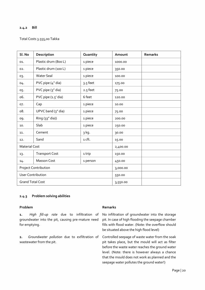
2.4.2 Bill
Total Costs 3.555,00 Takka
Sl. No Description Quantity Amount Remarks
01. Plastic drum (800 L) 1 piece 1000.00
02. Plastic drum (100 L) 1 piece 350.00
03. Water Seal 1 piece 100.00
04. PVC pipe (4” dia) 3.5 feet 175.00
05. PVC pipe (3” dia) 2.5 feet 75.00
06. PVC pipe (1.5’ dia) 6 feet 120.00
07. Cap 1 piece 10.00
08. UPVC band (3” dia) 1 piece 75.00
09. Ring (33” dia)) 1 piece 200.00
10. Slab 1 piece 250.00
11. Cement 3 kg. 30.00
12. Sand 1 cft. 15.00
Material Cost 2,400.00
13. Transport Cost 1 trip 150.00
14. Masson Cost 1 person 450.00
Project Contribution 3,000.00
User Contribution 550.00
Grand Total Cost 3,550.00
2.4.3 Problem solving abilities
Problem Remarks
1. High fill-up rate due to infiltration of
groundwater into the pit, causing pre-mature need
for emptying.
No infiltration of groundwater into the storage
pit. In case of high flooding the seepage chamber
fills with flood water. (Note: the overflow should
be situated above the high flood level)
2. Groundwater pollution due to exfiltration of
wastewater from the pit.
Controlled seepage of waste water from the soak
pit takes place, but the mould will act as filter
before the waste water reaches the ground water
level. (Note: there is however always a chance
that the mould does not work as planned and the
seepage water pollutes the ground water!)
Page | 21
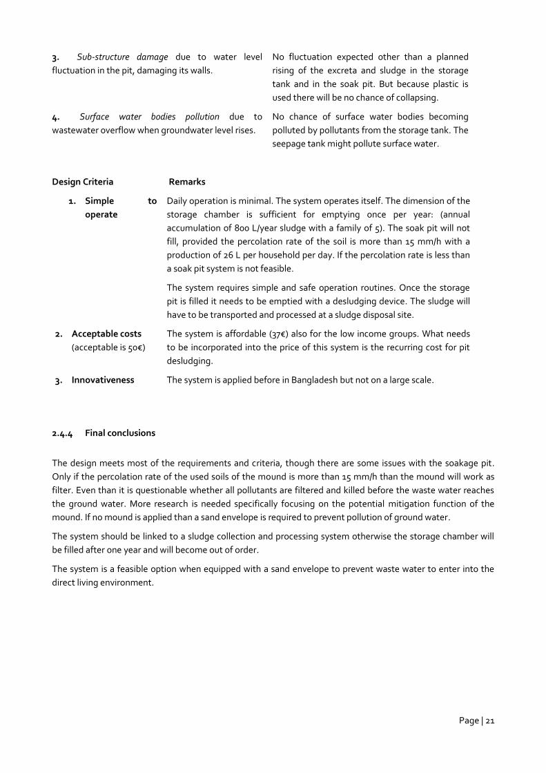
3. Sub-structure damage due to water level
fluctuation in the pit, damaging its walls.
No fluctuation expected other than a planned
rising of the excreta and sludge in the storage
tank and in the soak pit. But because plastic is
used there will be no chance of collapsing.
4. Surface water bodies pollution due to
wastewater overflow when groundwater level rises.
No chance of surface water bodies becoming
polluted by pollutants from the storage tank. The
seepage tank might pollute surface water.
Design Criteria Remarks
1. Simple to
operate
Daily operation is minimal. The system operates itself. The dimension of the
storage chamber is sufficient for emptying once per year: (annual
accumulation of 800 L/year sludge with a family of 5). The soak pit will not
fill, provided the percolation rate of the soil is more than 15 mm/h with a
production of 26 L per household per day. If the percolation rate is less than
a soak pit system is not feasible.
The system requires simple and safe operation routines. Once the storage
pit is filled it needs to be emptied with a desludging device. The sludge will
have to be transported and processed at a sludge disposal site.
2. Acceptable costs
(acceptable is 50€)
The system is affordable (37€) also for the low income groups. What needs
to be incorporated into the price of this system is the recurring cost for pit
desludging.
3. Innovativeness The system is applied before in Bangladesh but not on a large scale.
2.4.4 Final conclusions
The design meets most of the requirements and criteria, though there are some issues with the soakage pit.
Only if the percolation rate of the used soils of the mound is more than 15 mm/h than the mound will work as
filter. Even than it is questionable whether all pollutants are filtered and killed before the waste water reaches
the ground water. More research is needed specifically focusing on the potential mitigation function of the
mound. If no mound is applied than a sand envelope is required to prevent pollution of ground water.
The system should be linked to a sludge collection and processing system otherwise the storage chamber will
be filled after one year and will become out of order.
The system is a feasible option when equipped with a sand envelope to prevent waste water to enter into the
direct living environment.
Page | 22
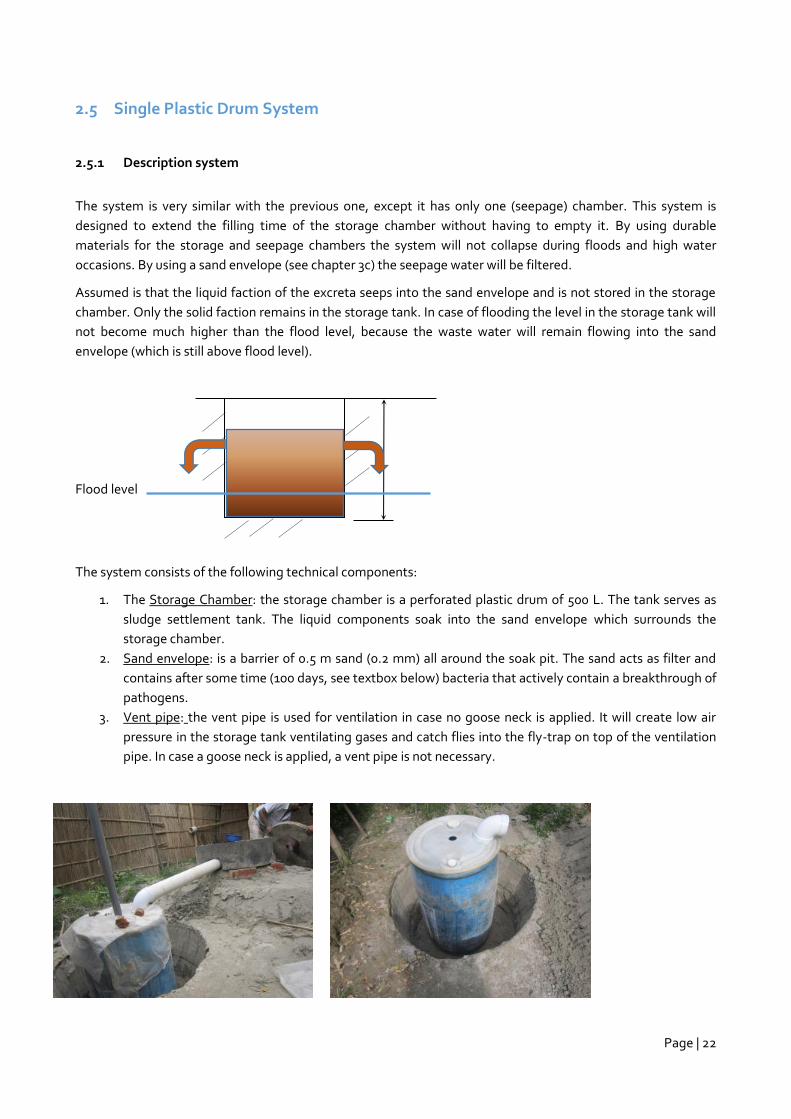
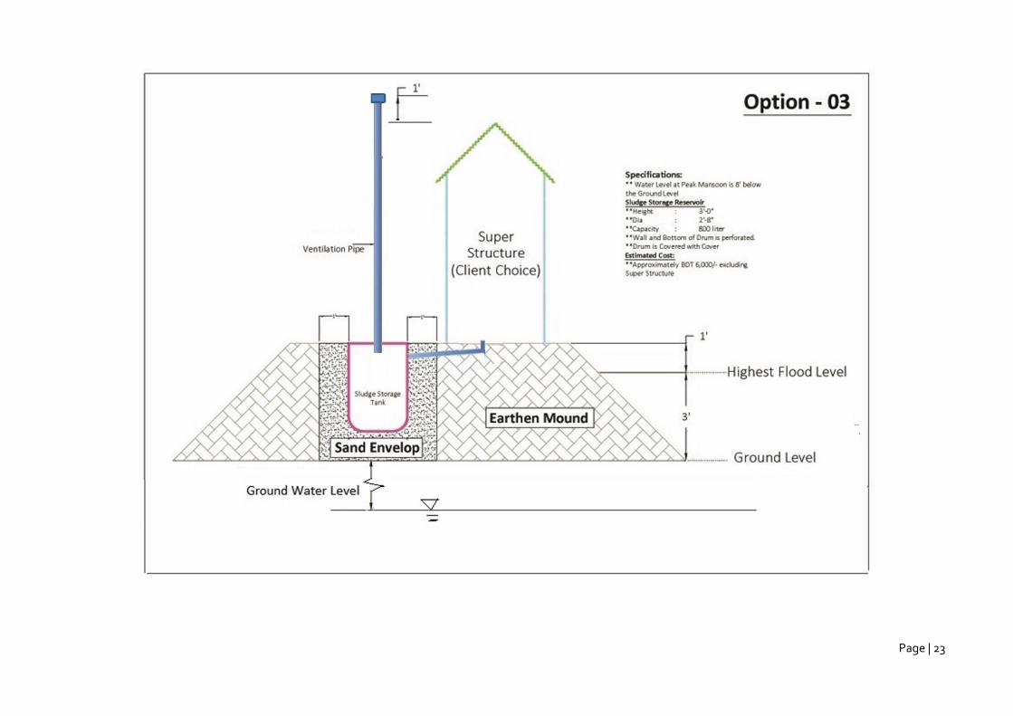
2.5 Single Plastic Drum System
2.5.1 Description system
The system is very similar with the previous one, except it has only one (seepage) chamber. This system is
designed to extend the filling time of the storage chamber without having to empty it. By using durable
materials for the storage and seepage chambers the system will not collapse during floods and high water
occasions. By using a sand envelope (see chapter 3c) the seepage water will be filtered.
Assumed is that the liquid faction of the excreta seeps into the sand envelope and is not stored in the storage
chamber. Only the solid faction remains in the storage tank. In case of flooding the level in the storage tank will
not become much higher than the flood level, because the waste water will remain flowing into the sand
envelope (which is still above flood level).
Flood level
The system consists of the following technical components:
1. The Storage Chamber: the storage chamber is a perforated plastic drum of 500 L. The tank serves as
sludge settlement tank. The liquid components soak into the sand envelope which surrounds the
storage chamber.
2. Sand envelope: is a barrier of 0.5 m sand (0.2 mm) all around the soak pit. The sand acts as filter and
contains after some time (100 days, see textbox below) bacteria that actively contain a breakthrough of
pathogens.
3. Vent pipe: the vent pipe is used for ventilation in case no goose neck is applied. It will create low air
pressure in the storage tank ventilating gases and catch flies into the fly-trap on top of the ventilation
pipe. In case a goose neck is applied, a vent pipe is not necessary.
Page | 23
Page | 24
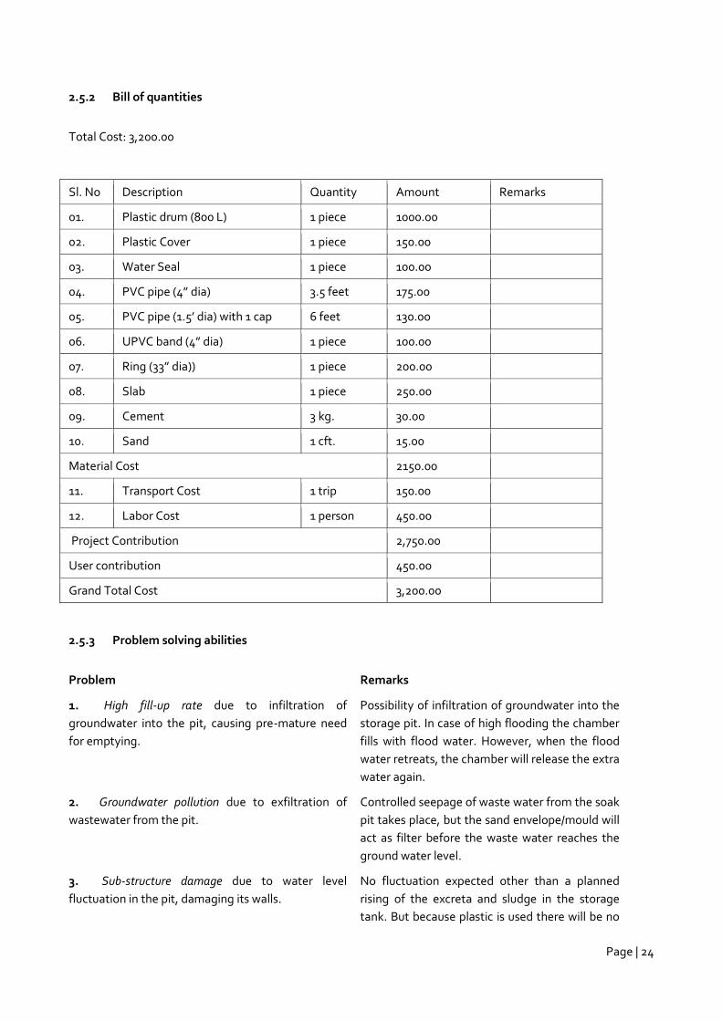
2.5.2 Bill of quantities
Total Cost: 3,200.00
Sl. No Description Quantity Amount Remarks
01. Plastic drum (800 L) 1 piece 1000.00
02. Plastic Cover 1 piece 150.00
03. Water Seal 1 piece 100.00
04. PVC pipe (4” dia) 3.5 feet 175.00
05. PVC pipe (1.5’ dia) with 1 cap 6 feet 130.00
06. UPVC band (4” dia) 1 piece 100.00
07. Ring (33” dia)) 1 piece 200.00
08. Slab 1 piece 250.00
09. Cement 3 kg. 30.00
10. Sand 1 cft. 15.00
Material Cost 2150.00
11. Transport Cost 1 trip 150.00
12. Labor Cost 1 person 450.00
Project Contribution 2,750.00
User contribution 450.00
Grand Total Cost 3,200.00
2.5.3 Problem solving abilities
Problem Remarks
1. High fill-up rate due to infiltration of
groundwater into the pit, causing pre-mature need
for emptying.
Possibility of infiltration of groundwater into the
storage pit. In case of high flooding the chamber
fills with flood water. However, when the flood
water retreats, the chamber will release the extra
water again.
2. Groundwater pollution due to exfiltration of
wastewater from the pit.
Controlled seepage of waste water from the soak
pit takes place, but the sand envelope/mould will
act as filter before the waste water reaches the
ground water level.
3. Sub-structure damage due to water level
fluctuation in the pit, damaging its walls.
No fluctuation expected other than a planned
rising of the excreta and sludge in the storage
tank. But because plastic is used there will be no
Page | 25
chance of collapsing.
4. Surface water bodies pollution due to
wastewater overflow when groundwater level rises.
No chance of surface water bodies becoming
polluted by pollutants from the storage tank
because of the mould.
Design Criteria Remarks
1. Simple to
operate
Daily operation is minimal. The system operates itself. The capacity of the
storage chamber is a bit on the small size for emptying once per year:
(annual accumulation of 700 lts/year sludge with a family of 6). Assumed a
percolation rate of the soil is more than 15 mm/h, the liquids will seep into
the envelope.
The system requires simple and safe operation routines. Once the storage
pit is filled it needs to be emptied with a desludging device. The sludge will
have to be transported and processed at a sludge disposal site.
2. Acceptable costs
(acceptable is 50€)
The system is affordable (34€) also for the low income groups. What needs
to be incorporated into the price of this system is the recurring cost for pit
desludging.
3. Innovativeness The system is applied before in Bangladesh but not on a large scale.
2.5.4 Final conclusions
The design meets all requirements and criteria.
The drum of 800 L as mentioned in the drawing is enough when assumed that all liquids will seep into the sand
envelope and the mound. A minimum volume of 700 L is required with an emptying period of 1 year.
The system should be linked to a sludge collection and processing system otherwise the storage chamber will
be filed after one year and no longer in operation.
Page | 26
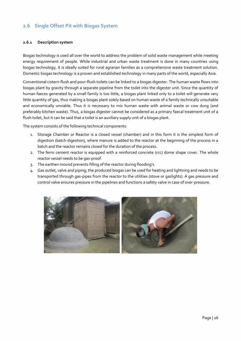
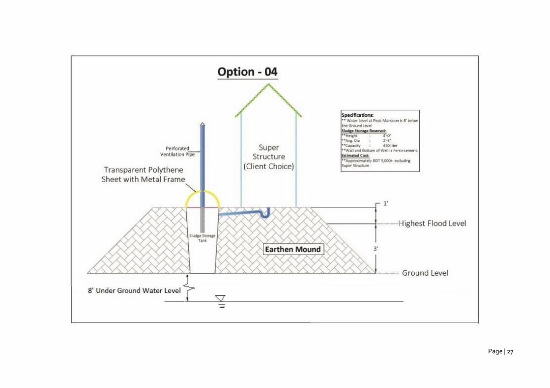
2.6 Single Offset Pit with Biogas System
2.6.1 Description system
Biogas technology is used all over the world to address the problem of solid waste management while meeting
energy requirement of people. While industrial and urban waste treatment is done in many countries using
biogas technology, it is ideally suited for rural agrarian families as a comprehensive waste treatment solution.
Domestic biogas technology is a proven and established technology in many parts of the world, especially Asia.
Conventional cistern-flush and pour-flush toilets can be linked to a biogas digester. The human waste flows into
biogas plant by gravity through a separate pipeline from the toilet into the digester unit. Since the quantity of
human faeces generated by a small family is too little, a biogas plant linked only to a toilet will generate very
little quantity of gas, thus making a biogas plant solely based on human waste of a family technically unsuitable
and economically unviable. Thus it is necessary to mix human waste with animal waste or cow dung (and
preferably kitchen waste). Thus, a biogas digester cannot be considered as a primary faecal treatment unit of a
flush toilet, but it can be said that a toilet is an auxiliary supply unit of a biogas plant.
The system consists of the following technical components:
1. Storage Chamber or Reactor is a closed vessel (chamber) and in this form it is the simplest form of
digestion (batch digestion), where manure is added to the reactor at the beginning of the process in a
batch and the reactor remains closed for the duration of the process.
2. The ferro cement reactor is equipped with a reinforced concrete (rcc) dome shape cover. The whole
reactor vessel needs to be gas-proof.
3. The earthen mound prevents filling of the reactor during flooding’s.
4. Gas outlet, valve and piping; the produced biogas can be used for heating and lightning and needs to be
transported through gas-pipes from the reactor to the utilities (stove or gaslights). A gas pressure and
control valve ensures pressure in the pipelines and functions a safety valve in case of over-pressure.
Page | 27
Page | 28
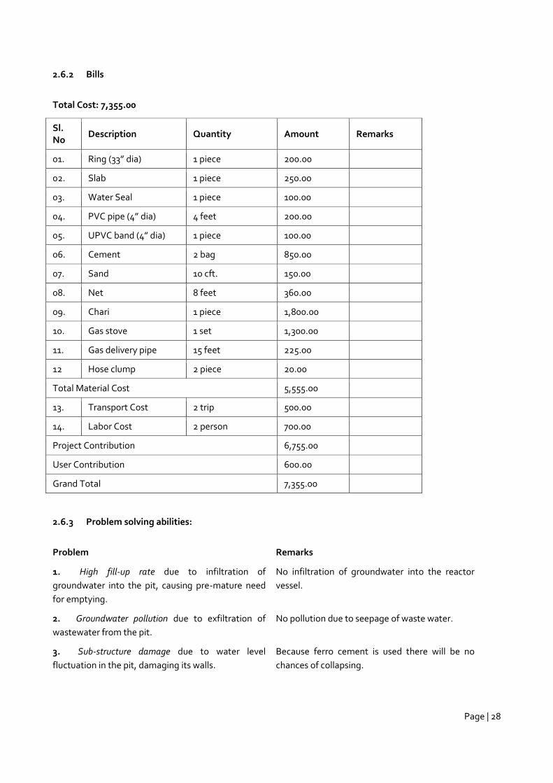
2.6.2 Bills
Total Cost: 7,355.00
Sl. No
Description Quantity Amount Remarks
01. Ring (33” dia) 1 piece 200.00
02. Slab 1 piece 250.00
03. Water Seal 1 piece 100.00
04. PVC pipe (4” dia) 4 feet 200.00
05. UPVC band (4” dia) 1 piece 100.00
06. Cement 2 bag 850.00
07. Sand 10 cft. 150.00
08. Net 8 feet 360.00
09. Chari 1 piece 1,800.00
10. Gas stove 1 set 1,300.00
11. Gas delivery pipe 15 feet 225.00
12 Hose clump 2 piece 20.00
Total Material Cost 5,555.00
13. Transport Cost 2 trip 500.00
14. Labor Cost 2 person 700.00
Project Contribution 6,755.00
User Contribution 600.00
Grand Total 7,355.00
2.6.3 Problem solving abilities:
Problem Remarks
1. High fill-up rate due to infiltration of
groundwater into the pit, causing pre-mature need
for emptying.
No infiltration of groundwater into the reactor
vessel.
2. Groundwater pollution due to exfiltration of
wastewater from the pit.
No pollution due to seepage of waste water.
3. Sub-structure damage due to water level
fluctuation in the pit, damaging its walls.
Because ferro cement is used there will be no
chances of collapsing.
Page | 29
4. Surface water bodies pollution due to
wastewater overflow when groundwater level rises.
No chance of surface water bodies becoming
polluted by pollutants from the reactor vessel.
Design Criteria Remarks
1. Simple to operate Daily operation is more complex. Though the system operates itself it needs
maintenance and care. In case the gas production is low organic wastes from
manure or kitchen waste needs to be added. On a regular basis the reactor
vessel needs to be emptied.
The system requires simple and safe operation routines.
2. Acceptable costs
(acceptable is 50€)
The system becomes affordable (77€) when the costs for fuel wood and/or
lightning is included. The investment might be high for the low income
groups.
3. Innovativeness The system is applied before in Bangladesh.
2.6.4 Final conclusions
The design meets most of the requirements and criteria, though the investment cost might be too high for the
very low income groups. The system generates however benefits which can be easily converted into costs (fuel
wood and gas for lightning) which on the long run might make I worthwhile to invest in this system despite its
initial high investment costs.
There might be an issue about the gas-production, which might be low when only using wastes from humans. It
is advised to equip the system with a device which makes it possible to add kitchen waste or animal manure.
The mixture of animal/plant organic matter and human wastes will generate more biogas.
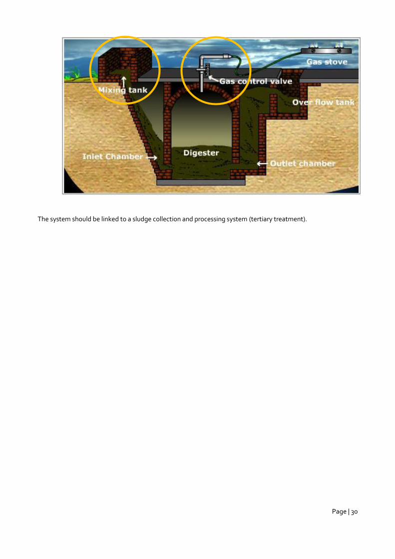
The demonstration unit did not produce much gas yet. The model needs to be extended with facilities that
make it possible to introduce organic wastes into the reactor vessel (kitchen wastes and animal wastes) and to
regulate the gas pressure (see picture below).
Page | 30
The system should be linked to a sludge collection and processing system (tertiary treatment).
Page | 31
2.7 Step latrine (models 1 & 2)
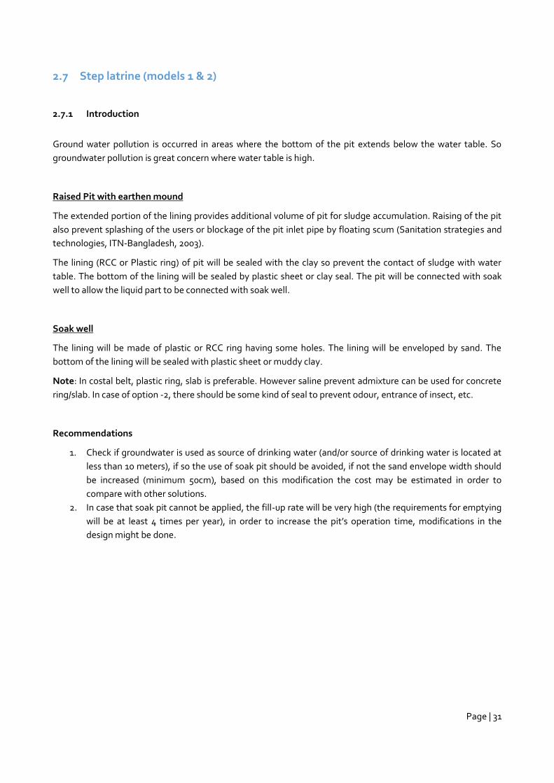
2.7.1 Introduction
Ground water pollution is occurred in areas where the bottom of the pit extends below the water table. So
groundwater pollution is great concern where water table is high.
Raised Pit with earthen mound
The extended portion of the lining provides additional volume of pit for sludge accumulation. Raising of the pit
also prevent splashing of the users or blockage of the pit inlet pipe by floating scum (Sanitation strategies and
technologies, ITN-Bangladesh, 2003).
The lining (RCC or Plastic ring) of pit will be sealed with the clay so prevent the contact of sludge with water
table. The bottom of the lining will be sealed by plastic sheet or clay seal. The pit will be connected with soak
well to allow the liquid part to be connected with soak well.
Soak well
The lining will be made of plastic or RCC ring having some holes. The lining will be enveloped by sand. The
bottom of the lining will be sealed with plastic sheet or muddy clay.
Note: In costal belt, plastic ring, slab is preferable. However saline prevent admixture can be used for concrete
ring/slab. In case of option -2, there should be some kind of seal to prevent odour, entrance of insect, etc.
Recommendations
1. Check if groundwater is used as source of drinking water (and/or source of drinking water is located at
less than 10 meters), if so the use of soak pit should be avoided, if not the sand envelope width should
be increased (minimum 50cm), based on this modification the cost may be estimated in order to
compare with other solutions.
2. In case that soak pit cannot be applied, the fill-up rate will be very high (the requirements for emptying
will be at least 4 times per year), in order to increase the pit’s operation time, modifications in the
design might be done.
Page | 32
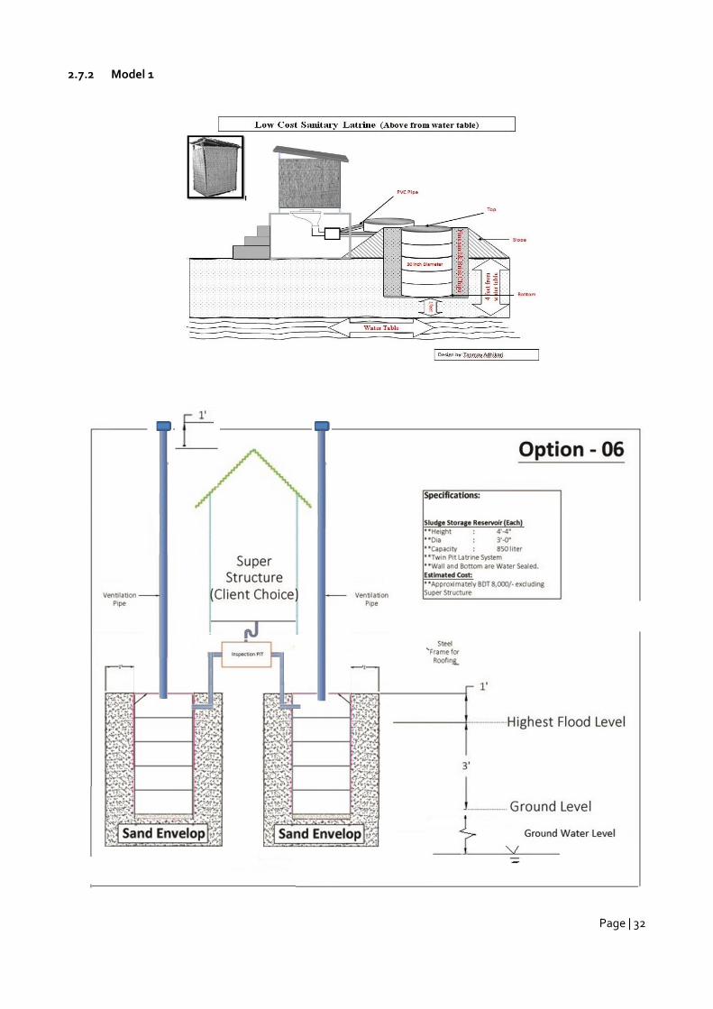
2.7.2 Model 1
Page | 33
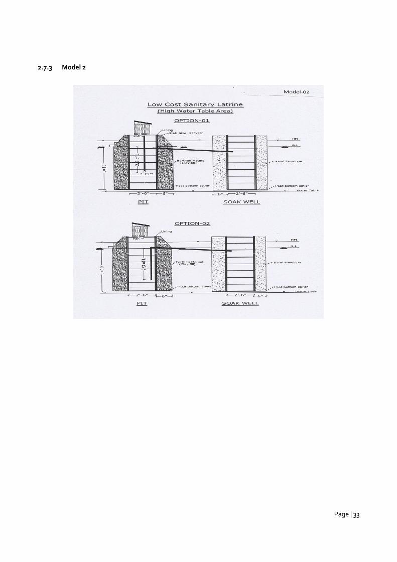
2.7.3 Model 2
Page | 34
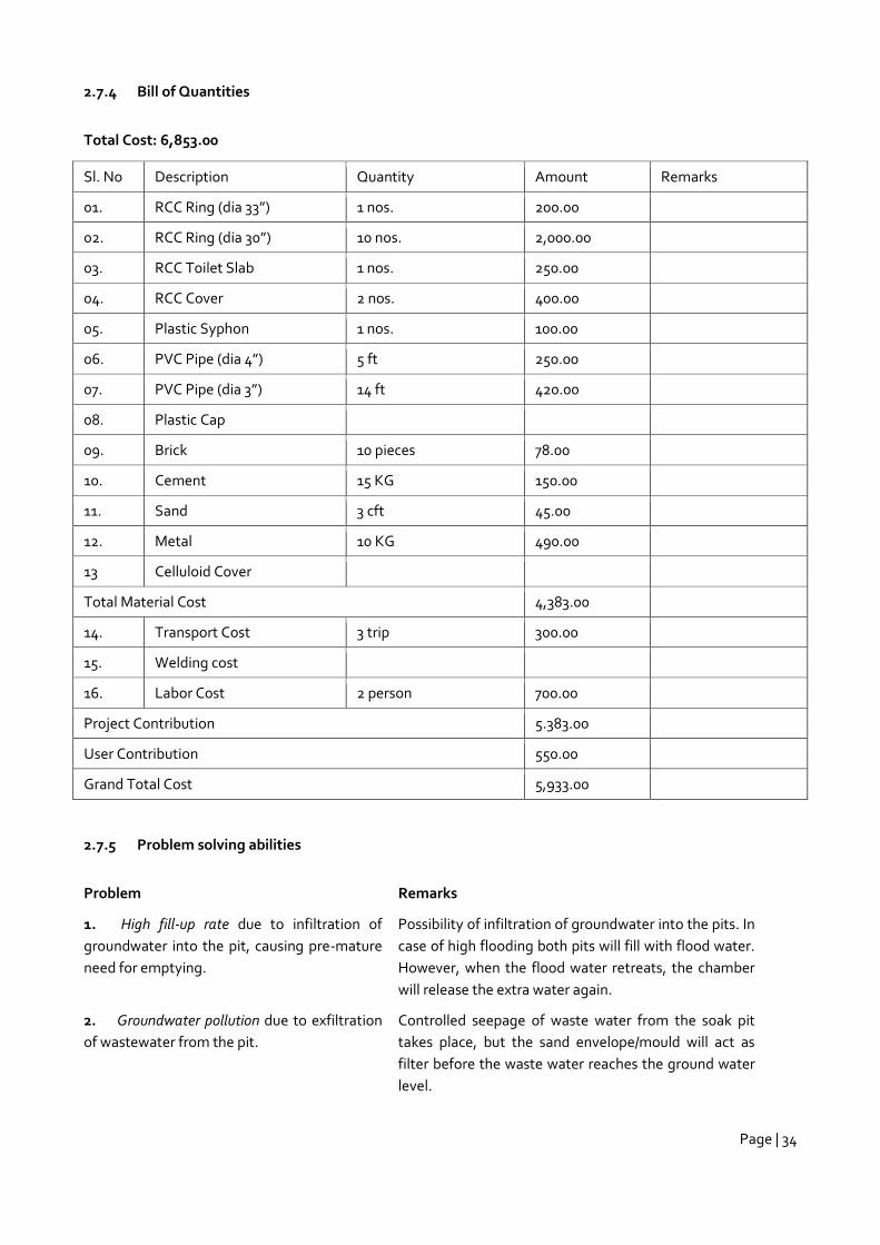
2.7.4 Bill of Quantities
Total Cost: 6,853.00
Sl. No Description Quantity Amount Remarks
01. RCC Ring (dia 33”) 1 nos. 200.00
02. RCC Ring (dia 30”) 10 nos. 2,000.00
03. RCC Toilet Slab 1 nos. 250.00
04. RCC Cover 2 nos. 400.00
05. Plastic Syphon 1 nos. 100.00
06. PVC Pipe (dia 4”) 5 ft 250.00
07. PVC Pipe (dia 3”) 14 ft 420.00
08. Plastic Cap
09. Brick 10 pieces 78.00
10. Cement 15 KG 150.00
11. Sand 3 cft 45.00
12. Metal 10 KG 490.00
13 Celluloid Cover
Total Material Cost 4,383.00
14. Transport Cost 3 trip 300.00
15. Welding cost
16. Labor Cost 2 person 700.00
Project Contribution 5.383.00
User Contribution 550.00
Grand Total Cost 5,933.00
2.7.5 Problem solving abilities
Problem Remarks
1. High fill-up rate due to infiltration of
groundwater into the pit, causing pre-mature
need for emptying.
Possibility of infiltration of groundwater into the pits. In
case of high flooding both pits will fill with flood water.
However, when the flood water retreats, the chamber
will release the extra water again.
2. Groundwater pollution due to exfiltration
of wastewater from the pit.
Controlled seepage of waste water from the soak pit
takes place, but the sand envelope/mould will act as
filter before the waste water reaches the ground water
level.
Page | 35
3. Sub-structure damage due to water level
fluctuation in the pit, damaging its walls.
No fluctuation expected other than a planned rising of
the excreta and sludge in the storage tank. But because
concrete rings are used there will be no chance of
collapsing.
4. Surface water bodies pollution due to
wastewater overflow when groundwater level
rises.
No chance of surface water bodies becoming polluted
by pollutants from the pit because of the mould/sand
envelope.
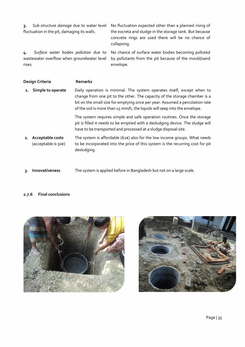
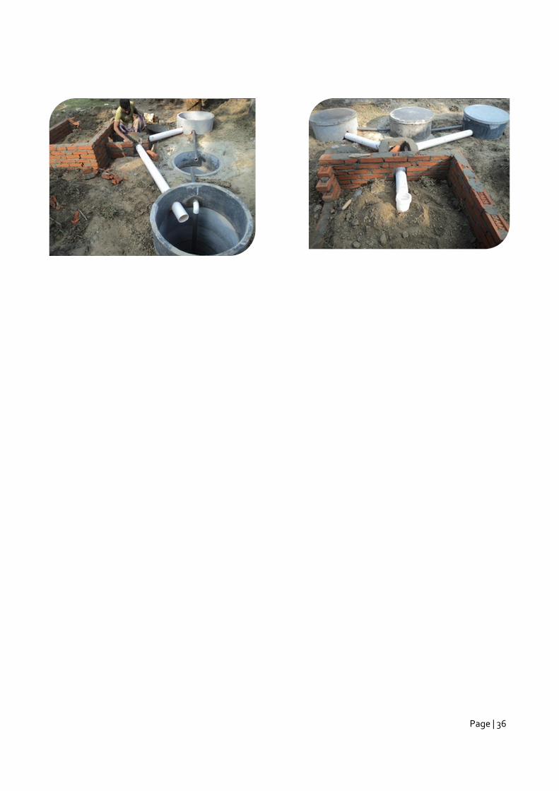
Design Criteria Remarks
1. Simple to operate Daily operation is minimal. The system operates itself, except when to
change from one pit to the other. The capacity of the storage chamber is a
bit on the small size for emptying once per year: Assumed a percolation rate
of the soil is more than 15 mm/h, the liquids will seep into the envelope.
The system requires simple and safe operation routines. Once the storage
pit is filled it needs to be emptied with a desludging device. The sludge will
have to be transported and processed at a sludge disposal site.
2. Acceptable costs
(acceptable is 50€)
The system is affordable (62€) also for the low income groups. What needs
to be incorporated into the price of this system is the recurring cost for pit
desludging.
3. Innovativeness The system is applied before in Bangladesh but not on a large scale.
2.7.6 Final conclusions
Page | 36
Page | 37
3 Alternative Materials
3.1 Use of BRCC
Since cost was a consideration, alternate building materials were considered. The data available on availability
and quality of Bamboo plus various studies on the tensile strength of seasoned bamboo which can provide 20-
30 % of that of Tor steel, was very encouraging. The specific details available in the study presented in the
paper in International Journal of Engineering Research and Applications (April 2012) by C. S. Verma, V. M.
Chariar and R. Purohit indicated that more improvements to application of bamboo as a replacement for Tor
Steel in RCC was possible. However, such innovations were beyond the scope of the current research and hence
the area of cross section of 6-10 times that of steel was tentatively decided whenever and wherever bamboo
could be used.
The options under each type of soil/water table are given below.
Rocky with Soil
Bamboo Reinforced Cement Concrete (BRCC) Septic Tank with and Soak Pit with Concrete rings with
Sand/Pebble envelope around the Soak Pit
Twin BRCC Leach Pits with Sand/Pebble envelope around the pits
Clayey
Bamboo Reinforced Cement Concrete (BRCC) Septic Tank with and Soak Pit with Concrete rings with
Sand/Pebble envelope around the Soak Pit
Twin BRCC Leach Pits with Sand/Pebble envelope around the pits
High Water Table/Flood prone/Water logged-Elevated by mound method
No toilet types with BCC possible
High Water Table/Flood prone/Water logged-Elevated by supported sand bed method
No toilet types with BCC possible
Technical details
The Septic Tank and Soak Pit are constructed with Bamboo Reinforced Cement Concrete with superstructure
also of the same combination but a leaner mix or from GI sheets. The substructure, namely the Septic Tank and
Soak Pit, are of BRCC M20 (1:1.5:3). The wall too is of the same material but RCC M 15 (1:2:4). The roof is with
MS sheet and roof support is bamboo
Cost Reduction
The BRCC Septic Tank with Brickwork masonry Soak Pit costs BDT 42000/- per unit. The Leach Pits costs BDT
24, 000/- and BDT 20, 000/- respectively for flood prone and rocky/clayey areas. Cost of superstructure built in
the PDUs varied from BDT 40, 000/- to BDT 60, 000/-. However, that cost is flexible and more options for
materials of construction are available. The construction materials used for the superstructure in the PDUs are
GI sheets, BRCC and bricks. The details of materials used for the units and costs thereof are given in the
annexes. The ‘traditional’ ‘elevated toilets’ in the Lakhai area are reported to cost just around BDT 12, 000/-
only; but they can hardly be referred to as toilets but just elevated enclosures only
Page | 38
3.2 Use of Ferro Cement
Ferro Cement (FC) is a form of thin-shell construction that uses standard Portland cement, usually mixed with
plaster sand. Compared to traditional RCC construction, the cement is reinforced with more steel or fiber (with
a lesser diameter, typically wire-mesh) at a closer spacing. Reduced spacing yields uniform force dispersion and
increases strength. The well-distributed and aligned reinforcement can make the FC behave like steel plates. It
is offers possibilities for producing very thin and light-weight structures. The dependency on skilled labor is
reduced, since FC application is very simple and easy. FC construction complements compressed earth bricks in
many ways. FC has proven its applicability in many appliances in buildings and other construction features.
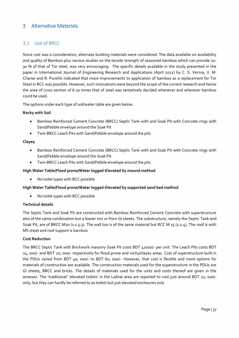
A cost comparison is made in the table below:
Ferro Cement Water Storage Tanks for Rain Water Harvesting in Hills & Islands
P.C. Sharma, 2005
The table shows a significant cost reduction between different building materials. Roughly it means that when
using Ferro Cement instead of RCC or masonry the cost reduction could be 50% or 43%.
3.3 Use of Sand Envelopes
Sand envelope is a barrier of 0.5 m sand (0.2 mm course sand) all around a soak pit. The sand acts as filter and
contains after some time (100 days, see textbox below) bacteria that actively contain a breakthrough of
pathogens. A sand envelope is a type of filter which is known as a slow sand filter.
Slow sand filtration has been an effective water treatment process for preventing the spread of gastrointestinal
diseases for over 150 years, having been used first in Great Britain and later in other European countries
Page | 39
(LOGSDON 2002). SFFs are still used in London and were relatively common in Western Europe until recently
and are still common elsewhere in the world.
3.3.1 Basic Design Principles
The basic principle of the process is very simple. Contaminated water flows through a layer of sand, where it not
only gets physically filtered but biologically treated. Hereby, both sediments and pathogens are removed. This
process is based on the ability of organisms to remove pathogens.
The physical removal of solids is an important part of the purification process and takes place in the
sedimentation tanks, the relevant aspect is the biological filtration. The top layers of the sand become
biologically active by the establishment of a microbial community on the top layer of the sand substrate, also
referred to as ‘schmutzdecke’. These microbes come from the source of the waste water and establish a
community within a matter of month (100 days). The fine sand and slow filtration rate facilitate the
establishment of this microbial community. The majority of the community are predatory bacteria that feed on
water-borne microbes passing through the filter (WHO n.y.). Hence, the underlying principle of the SSF is
equivalent to the bio-sand filtration. While the former is applied to semi-centralised water treatment, the latter
mainly serves household purposes.
As the process of biological filtration requires a fair amount of time in order to purify the water sufficiently, SSFs
usually operate at slow flow rates between 0.1 – 0.3 m3/h per square metre of surface (WHO n.y.). The water
thus remains in the space above the medium for several hours and larger particles are allowed to separate and
settle (see also sedimentation). It then passes through the sand-bed where it goes through a number of
purification processes (HUISMAN 1974).
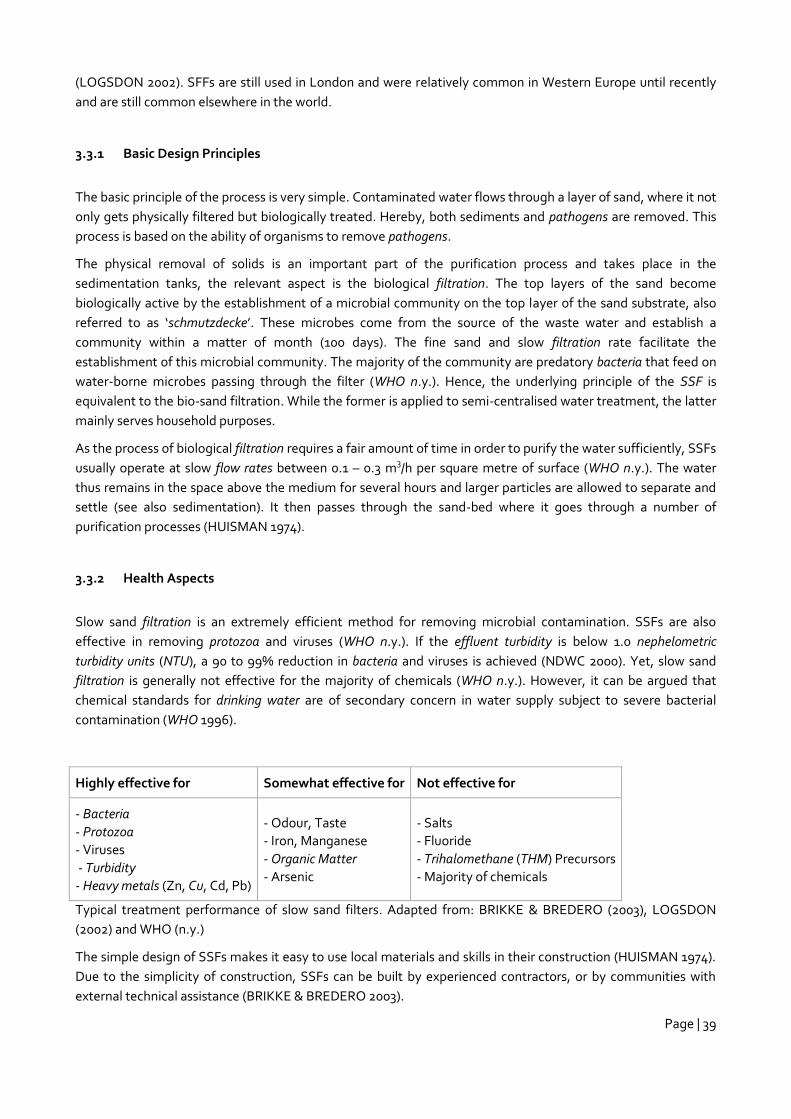
3.3.2 Health Aspects
Slow sand filtration is an extremely efficient method for removing microbial contamination. SSFs are also
effective in removing protozoa and viruses (WHO n.y.). If the effluent turbidity is below 1.0 nephelometric
turbidity units (NTU), a 90 to 99% reduction in bacteria and viruses is achieved (NDWC 2000). Yet, slow sand
filtration is generally not effective for the majority of chemicals (WHO n.y.). However, it can be argued that
chemical standards for drinking water are of secondary concern in water supply subject to severe bacterial
contamination (WHO 1996).
Highly effective for Somewhat effective for Not effective for
- Bacteria
- Protozoa
- Viruses
- Turbidity
- Heavy metals (Zn, Cu, Cd, Pb)
- Odour, Taste
- Iron, Manganese
- Organic Matter
- Arsenic
- Salts
- Fluoride
- Trihalomethane (THM) Precursors
- Majority of chemicals
Typical treatment performance of slow sand filters. Adapted from: BRIKKE & BREDERO (2003), LOGSDON
(2002) and WHO (n.y.)
The simple design of SSFs makes it easy to use local materials and skills in their construction (HUISMAN 1974).
Due to the simplicity of construction, SSFs can be built by experienced contractors, or by communities with
external technical assistance (BRIKKE & BREDERO 2003).
Page | 40
Where there is limited space between the base of the pit and the water table, the use of sand envelopes around
the base and sides of the pit are often recommended as this will help encourage an active biological community
to reduce breakthrough of pathogens (Franceys et al. 1992). These recommendations are based on original field
and laboratory experimentation by Coldwell and Parr (1937) and later by Ziebell et al. (1975). The former found
that a 0.25 metre envelope of sand provided an effective barrier to thermotolerant coliform movement.
However, although this provides confidence in control of bacterial contamination, confidence in control of viral
pathogens is more limited. Ziebell et al. (1975) found that development of the biological communities within
sand envelopes took up to 100 days, suggesting an initial period of elevated risk during the first use of the
latrine. (G. Howard, B. J. Reed, D. McChesney and R. Taylor, The Global Water Supply and Sanitation
Assessment 2000, WHO, 2000)
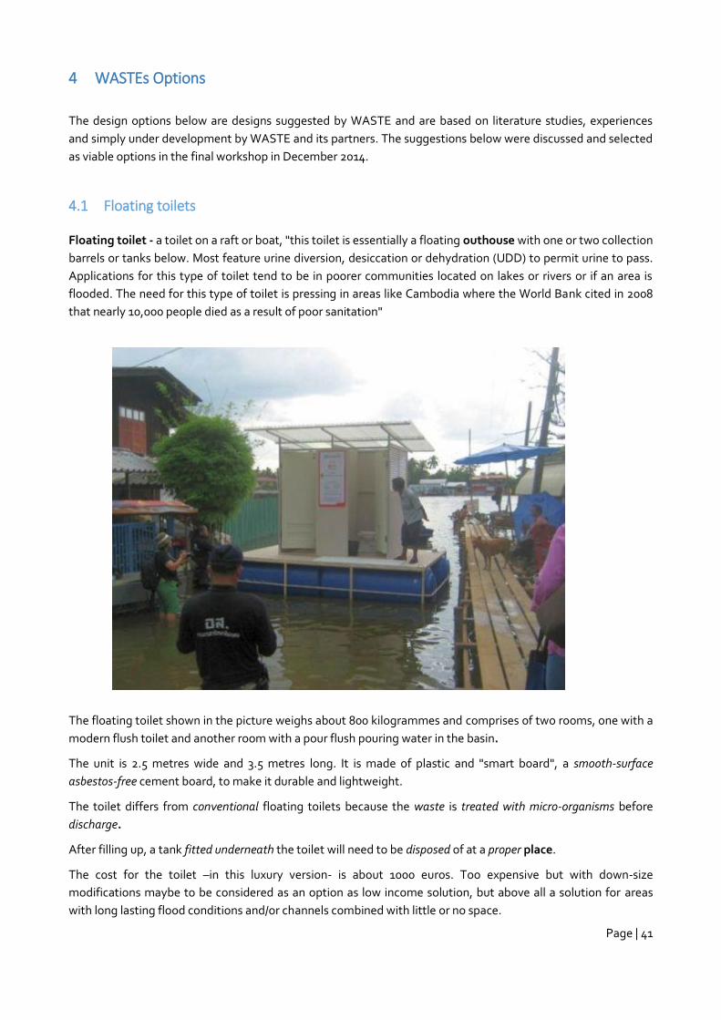
Page | 41
4 WASTEs Options
The design options below are designs suggested by WASTE and are based on literature studies, experiences
and simply under development by WASTE and its partners. The suggestions below were discussed and selected
as viable options in the final workshop in December 2014.
4.1 Floating toilets
Floating toilet - a toilet on a raft or boat, "this toilet is essentially a floating outhouse with one or two collection
barrels or tanks below. Most feature urine diversion, desiccation or dehydration (UDD) to permit urine to pass.
Applications for this type of toilet tend to be in poorer communities located on lakes or rivers or if an area is
flooded. The need for this type of toilet is pressing in areas like Cambodia where the World Bank cited in 2008
that nearly 10,000 people died as a result of poor sanitation"
The floating toilet shown in the picture weighs about 800 kilogrammes and comprises of two rooms, one with a
modern flush toilet and another room with a pour flush pouring water in the basin.
The unit is 2.5 metres wide and 3.5 metres long. It is made of plastic and "smart board", a smooth-surface
asbestos-free cement board, to make it durable and lightweight.
The toilet differs from conventional floating toilets because the waste is treated with micro-organisms before
discharge.
After filling up, a tank fitted underneath the toilet will need to be disposed of at a proper place.
The cost for the toilet –in this luxury version- is about 1000 euros. Too expensive but with down-size
modifications maybe to be considered as an option as low income solution, but above all a solution for areas
with long lasting flood conditions and/or channels combined with little or no space.
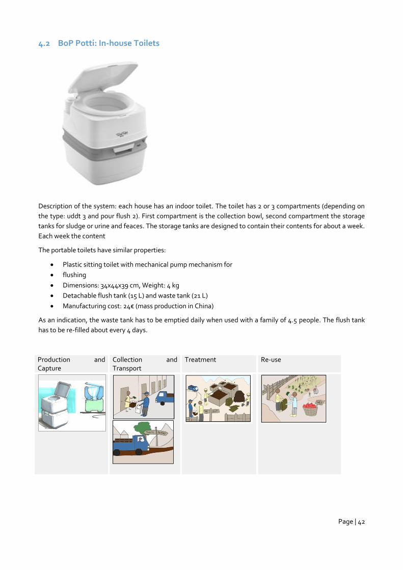
Page | 42
4.2 BoP Potti: In-house Toilets
Description of the system: each house has an indoor toilet. The toilet has 2 or 3 compartments (depending on
the type: uddt 3 and pour flush 2). First compartment is the collection bowl, second compartment the storage
tanks for sludge or urine and feaces. The storage tanks are designed to contain their contents for about a week.
Each week the content
The portable toilets have similar properties:
Plastic sitting toilet with mechanical pump mechanism for
flushing
Dimensions: 34x44x39 cm, Weight: 4 kg
Detachable flush tank (15 L) and waste tank (21 L)
Manufacturing cost: 24€ (mass production in China)
As an indication, the waste tank has to be emptied daily when used with a family of 4.5 people. The flush tank
has to be re-filled about every 4 days.
Production and Capture
Collection and Transport
Treatment Re-use
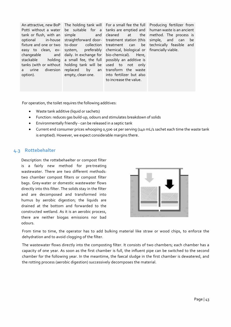
Page | 43
An attractive, new BoP Potti without a water tank or flush, with an optional in-house fixture and one or two easy to clean, ex-changeable and stackable holding tanks (with or without a urine diversion option).
The holding tank will be suitable for a simple and straightforward door-to-door collection system, preferably daily. In exchange for a small fee, the full holding tank will be replaced by an empty, clean one.
For a small fee the full tanks are emptied and cleaned at the treatment station (this treatment can be chemical, biological or bio-chemical). Here, possibly an additive is used to not only transform the waste into fertilizer but also to increase the value.
Producing fertilizer from human waste is an ancient method. The process is simple, and can be technically feasible and financially viable.
For operation, the toilet requires the following additives:
Waste tank additive (liquid or sachets)
Function: reduces gas build-up, odours and stimulates breakdown of solids
Environmentally friendly - can be released in a septic tank
Current end consumer prices whooping 0,50€-1€ per serving (140 mL/1 sachet each time the waste tank
is emptied). However, we expect considerable margins there.
4.3 Rottebehalter
Description: the rottebehaelter or compost filter
is a fairly new method for pre-treating
wastewater. There are two different methods:
two chamber compost filters or compost filter
bags. Grey-water or domestic wastewater flows
directly into this filter. The solids stay in the filter
and are decomposed and transformed into
humus by aerobic digestion; the liquids are
drained at the bottom and forwarded to the
constructed wetland. As it is an aerobic process,
there are neither biogas emissions nor bad
odours.
From time to time, the operator has to add bulking material like straw or wood chips, to enforce the
dehydration and to avoid clogging of the filter.
The wastewater flows directly into the composting filter. It consists of two chambers; each chamber has a
capacity of one year. As soon as the first chamber is full, the influent pipe can be switched to the second
chamber for the following year. In the meantime, the faecal sludge in the first chamber is dewatered, and
the rotting process (aerobic digestion) successively decomposes the material.
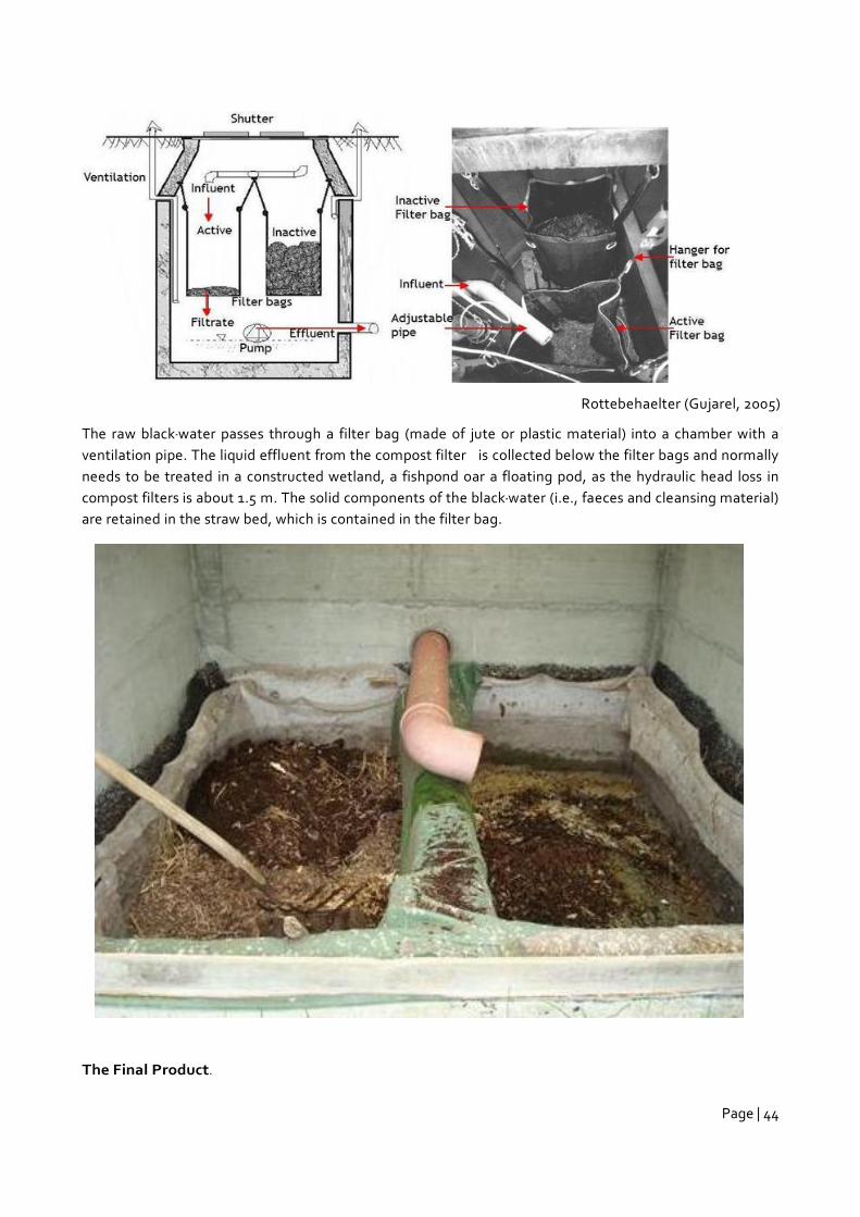
Page | 44
Rottebehaelter (Gujarel, 2005)
The raw black-water passes through a filter bag (made of jute or plastic material) into a chamber with a
ventilation pipe. The liquid effluent from the compost filter is collected below the filter bags and normally
needs to be treated in a constructed wetland, a fishpond oar a floating pod, as the hydraulic head loss in
compost filters is about 1.5 m. The solid components of the black-water (i.e., faeces and cleansing material)
are retained in the straw bed, which is contained in the filter bag.
The Final Product.
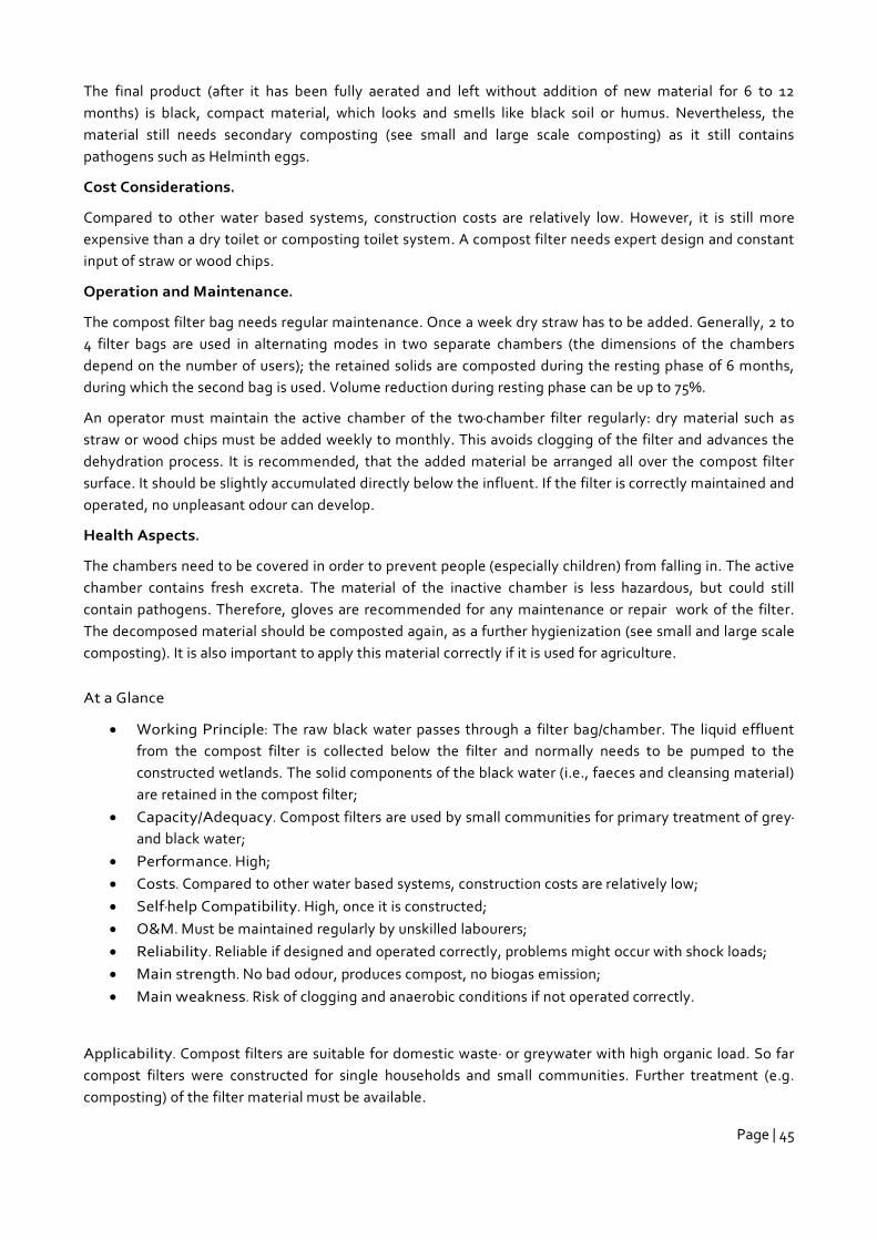
Page | 45
The final product (after it has been fully aerated and left without addition of new material for 6 to 12
months) is black, compact material, which looks and smells like black soil or humus. Nevertheless, the
material still needs secondary composting (see small and large scale composting) as it still contains
pathogens such as Helminth eggs.
Cost Considerations.
Compared to other water based systems, construction costs are relatively low. However, it is still more
expensive than a dry toilet or composting toilet system. A compost filter needs expert design and constant
input of straw or wood chips.
Operation and Maintenance.
The compost filter bag needs regular maintenance. Once a week dry straw has to be added. Generally, 2 to
4 filter bags are used in alternating modes in two separate chambers (the dimensions of the chambers
depend on the number of users); the retained solids are composted during the resting phase of 6 months,
during which the second bag is used. Volume reduction during resting phase can be up to 75%.
An operator must maintain the active chamber of the two-chamber filter regularly: dry material such as
straw or wood chips must be added weekly to monthly. This avoids clogging of the filter and advances the
dehydration process. It is recommended, that the added material be arranged all over the compost filter
surface. It should be slightly accumulated directly below the influent. If the filter is correctly maintained and
operated, no unpleasant odour can develop.
Health Aspects.
The chambers need to be covered in order to prevent people (especially children) from falling in. The active
chamber contains fresh excreta. The material of the inactive chamber is less hazardous, but could still
contain pathogens. Therefore, gloves are recommended for any maintenance or repair work of the filter.
The decomposed material should be composted again, as a further hygienization (see small and large scale
composting). It is also important to apply this material correctly if it is used for agriculture.
At a Glance
Working Principle: The raw black water passes through a filter bag/chamber. The liquid effluent
from the compost filter is collected below the filter and normally needs to be pumped to the
constructed wetlands. The solid components of the black water (i.e., faeces and cleansing material)
are retained in the compost filter;
Capacity/Adequacy. Compost filters are used by small communities for primary treatment of grey-
and black water;
Performance. High;
Costs. Compared to other water based systems, construction costs are relatively low;
Self-help Compatibility. High, once it is constructed;
O&M. Must be maintained regularly by unskilled labourers;
Reliability. Reliable if designed and operated correctly, problems might occur with shock loads;
Main strength. No bad odour, produces compost, no biogas emission;
Main weakness. Risk of clogging and anaerobic conditions if not operated correctly.
Applicability. Compost filters are suitable for domestic waste- or greywater with high organic load. So far
compost filters were constructed for single households and small communities. Further treatment (e.g.
composting) of the filter material must be available.
Page | 46
Advantages
The effluent (filtrate) from a compost filter has no unpleasant odour compared to anaerobic pre-
treatment systems (e.g. septic tanks);
There is no biogas production since it is an aerobic process;
Produces compost that can be used for gardening or farming;
Can be operated and maintained by everyone after a short training.
Disadvantages
Needs more “hands-on” maintenance than other pre-treatment method;
Use is limited to small units (decentralised wastewater treatment systems);
Compost filter bags only work with highly concentrated black-water, because too many solids may
be washed out of the filter bags otherwise;
Clogging may occur, usually due to having selected the wrong filter bags or substrate or due to bad
maintenance;
The leachate (liquid effluent) requires further treatment.
Page | 47
5 Monitoring of Designs
Toilet Options Monitoring Findings Recommendation
Modified Septic Tank System Drying rate of Waste water is satisfactory
Need to require more follow up to observe seasonal variations
Double Plastic Drum System Liquid soaked satisfactorily Need to modify sludge storage tank cover for easy de-sludging
Single Plastic Drum System Liquid soaked satisfactorily It may require more time to follow up.
Single Offset with Biogas System
Adequate Bio-gas is not generating till now.
Need to require more follow up or increase user.
Modified Twin Pit System Evaporation rate is relatively more compare to other options
Need to require more follow up to do some reliable remarks.
6 Conclusions & Recommendations
There is always a costs attached to more sustainable and more robust ways of constructing toilets. The
ideal to construct toilets at the same price as if there is no improvement made is not achievable
The proposed solutions are within an acceptable price range and solve some of the technical problems
linked to the geomorphological conditions of Bangladesh.
A combination of the different offered solutions will solve all problems
Local entrepreneurs provide valuable information on how to improve existing toilet systems, but their
designing and technical capacity is too limited to be able to make new innovations possible.
The sheer magnitude of the problems in Bangladesh related to sanitation demands a complete new
way of thinking and solutions. Onsite toilet systems as proposed need much space and resources. The
proposed BoP Potti might become a more attractive and effective way of disposing human wastes.
7 Combining designs
When considering all designs and recommendations the following design could be assembled from the previous
information
Alternative Design:
Principle: reduction of liquids through forced dehydration, use of cost saving materials and technologies and
saline resistant materials, combined with the principles of a Rottebehealter without the pumping systems and
use of wetlands.
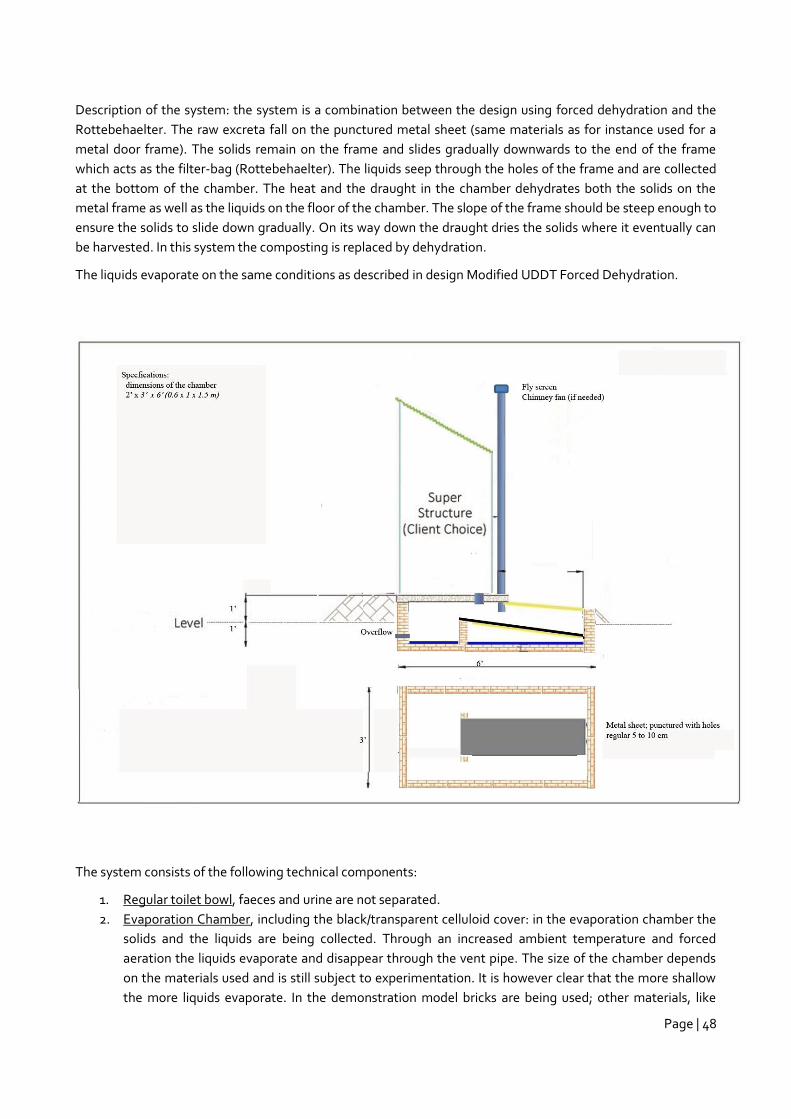
Page | 48
Description of the system: the system is a combination between the design using forced dehydration and the
Rottebehaelter. The raw excreta fall on the punctured metal sheet (same materials as for instance used for a
metal door frame). The solids remain on the frame and slides gradually downwards to the end of the frame
which acts as the filter-bag (Rottebehaelter). The liquids seep through the holes of the frame and are collected
at the bottom of the chamber. The heat and the draught in the chamber dehydrates both the solids on the
metal frame as well as the liquids on the floor of the chamber. The slope of the frame should be steep enough to
ensure the solids to slide down gradually. On its way down the draught dries the solids where it eventually can
be harvested. In this system the composting is replaced by dehydration.
The liquids evaporate on the same conditions as described in design Modified UDDT Forced Dehydration.
The system consists of the following technical components:
1. Regular toilet bowl, faeces and urine are not separated.
2. Evaporation Chamber, including the black/transparent celluloid cover: in the evaporation chamber the
solids and the liquids are being collected. Through an increased ambient temperature and forced
aeration the liquids evaporate and disappear through the vent pipe. The size of the chamber depends
on the materials used and is still subject to experimentation. It is however clear that the more shallow
the more liquids evaporate. In the demonstration model bricks are being used; other materials, like
Page | 49
black polyethylene tanks are also applicable especially when the heat build-up in the tanks becomes an
issue.
3. The evaporation tank can be constructed with 2 types of materials: bricks or polyethylene. The
polyethylene tanks should be used in high water and flooding conditions (to avoid infiltration of water).
The masonry tank should be used under dry conditions only. The masonry walls and floor are lined to
make the chamber watertight (see design 1A and 1B).
4. Punctured metal sheet, the sheet can be constructed of the same materials as a regular metal door
used for toilets (light materials). The sheet should be punctured with holes at a regular distance (every 5
to 10 cm).
5. Vent Pipe: the vent pipe is a crucial components. In both cases they generate the crucial draught
necessary to dehydrate and transport the evaporated liquids to the ambient air. In case the generated
draught is not sufficient a chimney fan should be mounted.
6. Earthen mound (optional): the demonstration toilet is being built on an earthen embankment (mound)
to avoid flooding of the toilet. The height of the mound (and the toilet slab) depends on the high water
level and the ground water level (see annex 7).
This system does not have any other output than dried solids and can be used as an alternative for the regular
UDDT in cases where disposing the washing water into the surroundings is an issue. But also in case when the
urine cannot be harvested due to social unacceptance or other reasons because the urine evaporates.
Cost Considerations:
Compared to the Modified UDDT Forced Dehydration (Design 1) and the Rottebehaelter construction costs are
relatively less, because the system does not make use of an extra sedimentation tank and no costs for pumps
and wetlands. Materials should be locally available. The chamber is however bigger than in the Forced
Dehydration UDDT.
Operation and maintenance
The system needs from time to time maintenance, the operator has to collect the dried solids from the metal
sheet. The dehydrated solids are -in principle- safe to handle. Temperatures and the prolonged retention time
in the chamber should ensure complete die-off of the pathogens I the solids. The operator has also to check
whether the solids are not accumulating on the metal sheet and are indeed slowly sliding down.
Health Aspects:
The chamber is a closed system and others than the operator cannot enter the chamber easily. There are 2
points where contamination might occur: when the solid are not fully sanitized and when the liquids are not
fully vaporised and the liquids leave the chamber through the overflow system.
Important Note: this system is not experimented with yet. The design is a combination of the Enviroloo, the
Modified UDDT and the Rottebehaelter and needs testing. Agreed was with Practical Action Bangladesh that
they would test the assumptions and if we can get the funds also field tested. If the system works
8 Way Forward
During the last workshop the participants agreed to keep on monitoring the operation of the demo-toilets. In
particular Practical Action was very interested to maintain the monitoring of the demonstration toilets.
Page | 50
Practical Action intends to further investigate the designs, see whether they can become cheaper and
eventually market the toilets on a larger scale in Bangladesh.
WASTE agreed to include the different designs in its projects in Asia and Africa and in particular in Zambia
where WASTE implements the SPA program situated in high ground water table areas. The designs will also
become part of the FINISH Learning Guide (part B).
The different partners were pleased by the pleasant collaboration among the partners and all expressed their
commitment to keep on collaborating further when it concerns sanitation in Bangladesh.
Practical Action is very much involved in the development of sludge management options. PA has several
promising demonstration projects. Practical Action intends to adjust the designs based on the requirements of
the sludge management alternatives.
During and after the workshop the desire was expressed to continue the collaboration in order to be able to
gain more knowledge on types of toilets in high water table and flooding areas. WASTE and Practical Action will
explore ways how this could materialize and see which organisations would like to participate.
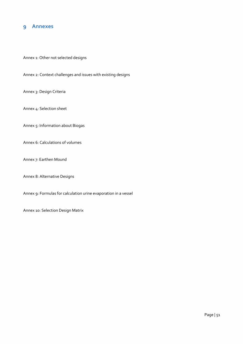
Page | 51
9 Annexes
Annex 1: Other not selected designs
Annex 2: Context challenges and issues with existing designs
Annex 3: Design Criteria
Annex 4: Selection sheet
Annex 5: Information about Biogas
Annex 6: Calculations of volumes
Annex 7: Earthen Mound
Annex 8: Alternative Designs
Annex 9: Formulas for calculation urine evaporation in a vessel
Annex 10: Selection Design Matrix
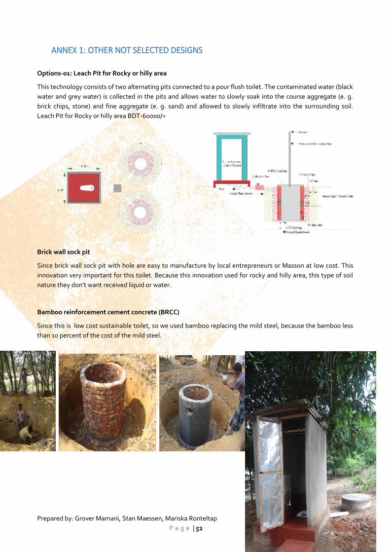
Prepared by: Grover Mamani, Stan Maessen, Mariska Ronteltap
P a g e | 52
ANNEX 1: OTHER NOT SELECTED DESIGNS
Options-01: Leach Pit for Rocky or hilly area
This technology consists of two alternating pits connected to a pour flush toilet. The contaminated water (black
water and grey water) is collected in the pits and allows water to slowly soak into the course aggregate (e. g.
brick chips, stone) and fine aggregate (e. g. sand) and allowed to slowly infiltrate into the surrounding soil.
Leach Pit for Rocky or hilly area BDT-60000/=
Brick wall sock pit
Since brick wall sock pit with hole are easy to manufacture by local entrepreneurs or Masson at low cost. This
innovation very important for this toilet. Because this innovation used for rocky and hilly area, this type of soil
nature they don’t want received liquid or water.
Bamboo reinforcement cement concrete (BRCC)
Since this is low cost sustainable toilet, so we used bamboo replacing the mild steel, because the bamboo less
than 10 percent of the cost of the mild steel.
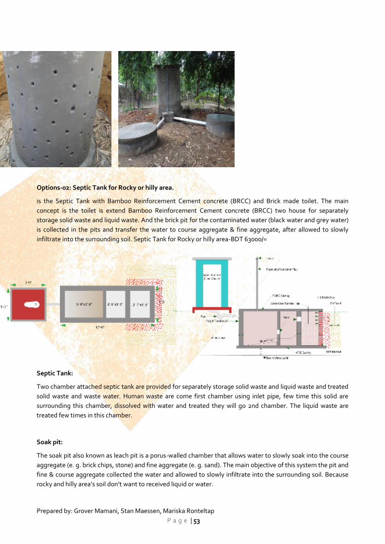
Prepared by: Grover Mamani, Stan Maessen, Mariska Ronteltap
P a g e | 53
Options-02: Septic Tank for Rocky or hilly area.
is the Septic Tank with Bamboo Reinforcement Cement concrete (BRCC) and Brick made toilet. The main
concept is the toilet is extend Bamboo Reinforcement Cement concrete (BRCC) two house for separately
storage solid waste and liquid waste. And the brick pit for the contaminated water (black water and grey water)
is collected in the pits and transfer the water to course aggregate & fine aggregate, after allowed to slowly
infiltrate into the surrounding soil. Septic Tank for Rocky or hilly area-BDT 63000/=
Septic Tank:
Two chamber attached septic tank are provided for separately storage solid waste and liquid waste and treated
solid waste and waste water. Human waste are come first chamber using inlet pipe, few time this solid are
surrounding this chamber, dissolved with water and treated they will go 2nd chamber. The liquid waste are
treated few times in this chamber.
Soak pit:
The soak pit also known as leach pit is a porus-walled chamber that allows water to slowly soak into the course
aggregate (e. g. brick chips, stone) and fine aggregate (e. g. sand). The main objective of this system the pit and
fine & course aggregate collected the water and allowed to slowly infiltrate into the surrounding soil. Because
rocky and hilly area’s soil don’t want to received liquid or water.
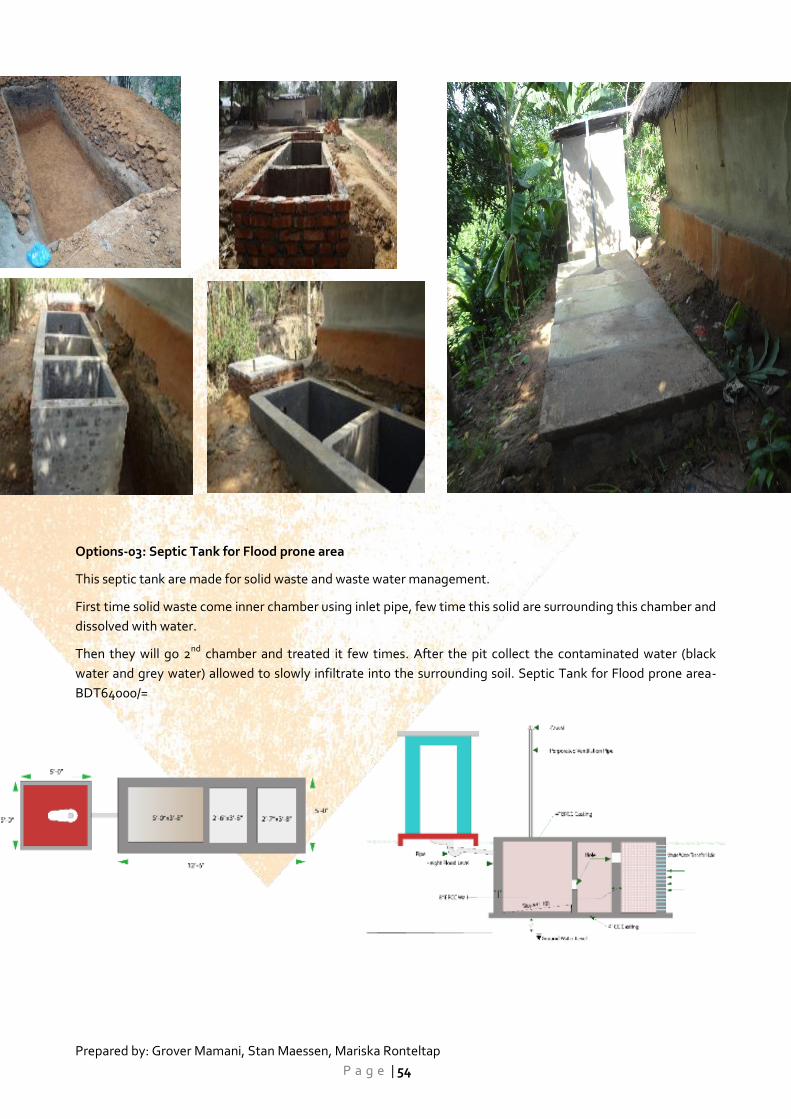
Prepared by: Grover Mamani, Stan Maessen, Mariska Ronteltap
P a g e | 54
Options-03: Septic Tank for Flood prone area
This septic tank are made for solid waste and waste water management.
First time solid waste come inner chamber using inlet pipe, few time this solid are surrounding this chamber and
dissolved with water.
Then they will go 2nd chamber and treated it few times. After the pit collect the contaminated water (black
water and grey water) allowed to slowly infiltrate into the surrounding soil. Septic Tank for Flood prone area-
BDT64000/=
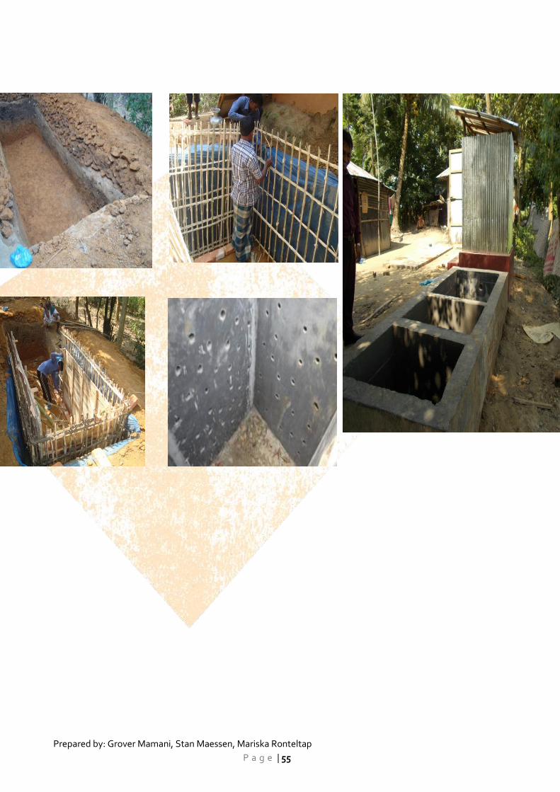
Prepared by: Grover Mamani, Stan Maessen, Mariska Ronteltap
P a g e | 55
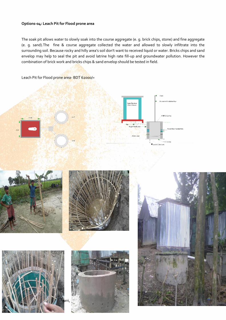
Prepared by: Grover Mamani, Stan Maessen, Mariska Ronteltap
P a g e | 56
Options-04: Leach Pit for Flood prone area
The soak pit allows water to slowly soak into the course aggregate (e. g. brick chips, stone) and fine aggregate
(e. g. sand).The fine & course aggregate collected the water and allowed to slowly infiltrate into the
surrounding soil. Because rocky and hilly area’s soil don’t want to received liquid or water. Bricks chips and sand
envelop may help to seal the pit and avoid latrine high rate fill-up and groundwater pollution. However the
combination of brick work and bricks chips & sand envelop should be tested in field.
Leach Pit for Flood prone area- BDT 62000/=
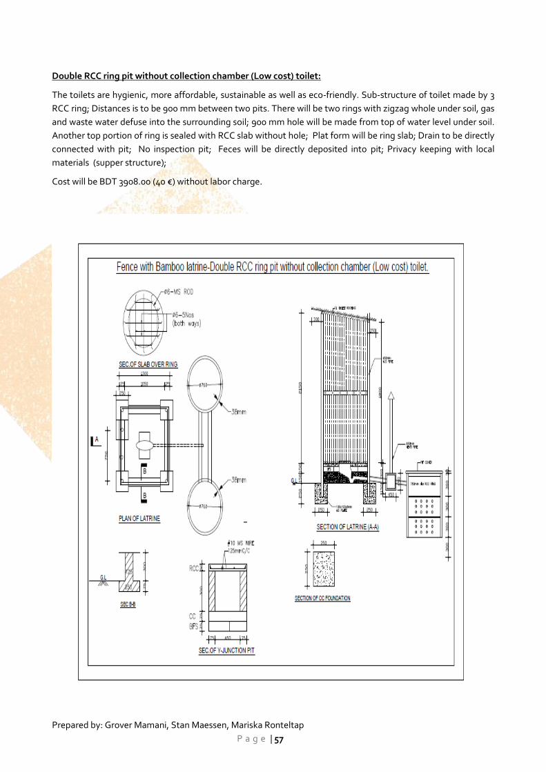
Prepared by: Grover Mamani, Stan Maessen, Mariska Ronteltap
P a g e | 57
Double RCC ring pit without collection chamber (Low cost) toilet:
The toilets are hygienic, more affordable, sustainable as well as eco-friendly. Sub-structure of toilet made by 3
RCC ring; Distances is to be 900 mm between two pits. There will be two rings with zigzag whole under soil, gas
and waste water defuse into the surrounding soil; 900 mm hole will be made from top of water level under soil.
Another top portion of ring is sealed with RCC slab without hole; Plat form will be ring slab; Drain to be directly
connected with pit; No inspection pit; Feces will be directly deposited into pit; Privacy keeping with local
materials (supper structure);
Cost will be BDT 3908.00 (40 €) without labor charge.
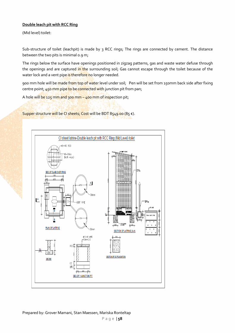
Prepared by: Grover Mamani, Stan Maessen, Mariska Ronteltap
P a g e | 58
Double leach pit with RCC Ring
(Mid level) toilet:
Sub-structure of toilet (leachpit) is made by 3 RCC rings; The rings are connected by cement. The distance
between the two pits is minimal 0.9 m;
The rings below the surface have openings positioned in zigzag patterns, gas and waste water defuse through
the openings and are captured in the surrounding soil; Gas cannot escape through the toilet because of the
water lock and a vent pipe is therefore no longer needed.
900 mm hole will be made from top of water level under soil; Pen will be set from 150mm back side after fixing
centre point; 450 mm pipe to be connected with junction pit from pan;
A hole will be 125 mm and 300 mm – 400 mm of inspection pit;
Supper structure will be CI sheets; Cost will be BDT 8549.00 (85 €).
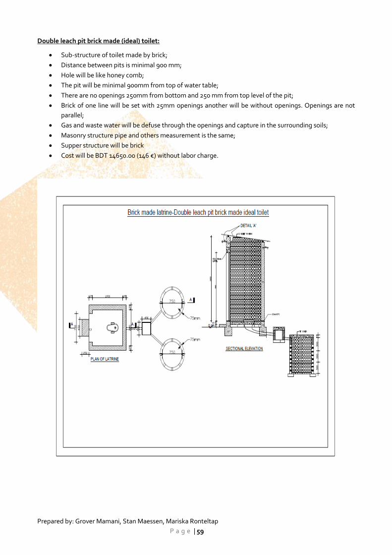
Prepared by: Grover Mamani, Stan Maessen, Mariska Ronteltap
P a g e | 59
Double leach pit brick made (ideal) toilet:
Sub-structure of toilet made by brick;
Distance between pits is minimal 900 mm;
Hole will be like honey comb;
The pit will be minimal 900mm from top of water table;
There are no openings 250mm from bottom and 250 mm from top level of the pit;
Brick of one line will be set with 25mm openings another will be without openings. Openings are not
parallel;
Gas and waste water will be defuse through the openings and capture in the surrounding soils;
Masonry structure pipe and others measurement is the same;
Supper structure will be brick
Cost will be BDT 14650.00 (146 €) without labor charge.
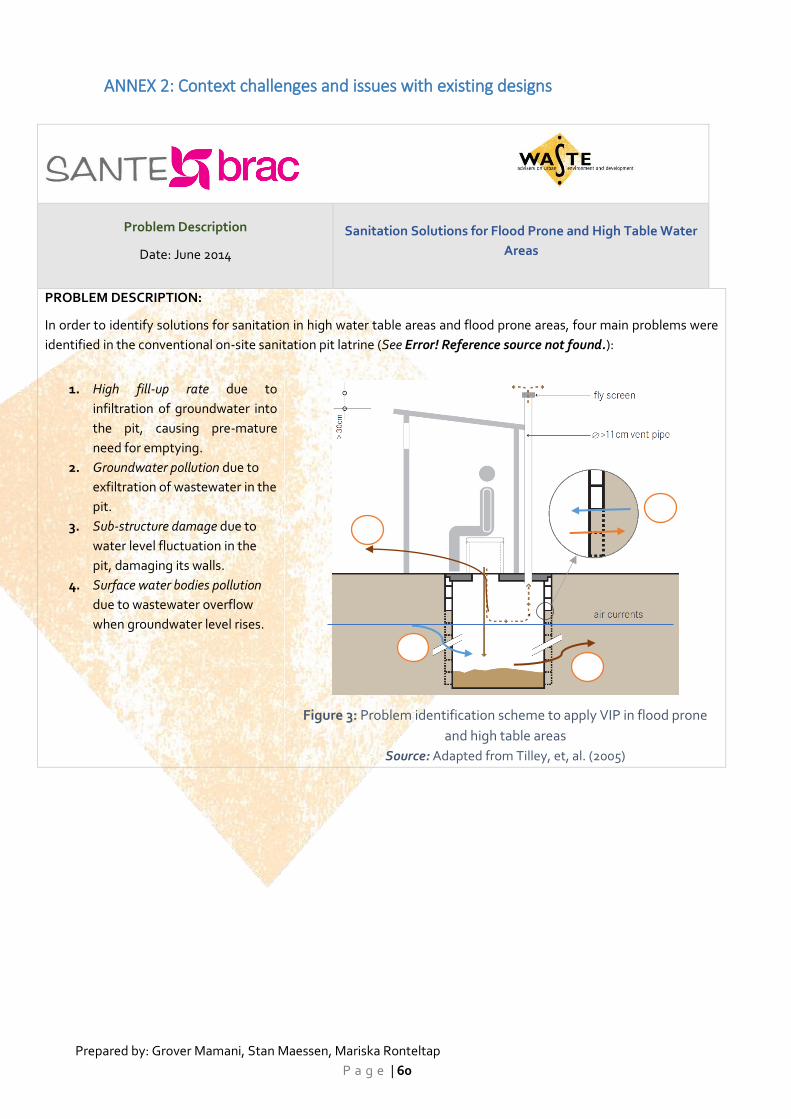
Prepared by: Grover Mamani, Stan Maessen, Mariska Ronteltap
P a g e | 60
ANNEX 2: Context challenges and issues with existing designs
Problem Description
Date: June 2014
Sanitation Solutions for Flood Prone and High Table Water
Areas
PROBLEM DESCRIPTION:
In order to identify solutions for sanitation in high water table areas and flood prone areas, four main problems were
identified in the conventional on-site sanitation pit latrine (See Error! Reference source not found.):
1. High fill-up rate due to
infiltration of groundwater into
the pit, causing pre-mature
need for emptying.
2. Groundwater pollution due to
exfiltration of wastewater in the
pit.
3. Sub-structure damage due to
water level fluctuation in the
pit, damaging its walls.
4. Surface water bodies pollution
due to wastewater overflow
when groundwater level rises.
Figure 3: Problem identification scheme to apply VIP in flood prone
and high table areas
Source: Adapted from Tilley, et, al. (2005)
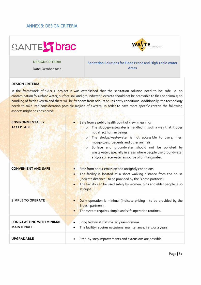
Page | 61
ANNEX 3: DESIGN CRITERIA
DESIGN CRITERIA
Date: October 2014
Sanitation Solutions for Flood Prone and High Table Water
Areas
DESIGN CRITERIA
In the framework of SANTE project it was established that the sanitation solution need to be: safe i.e. no
contamination fo surface water, surface soil and groundwater; excreta should not be accessible to flies or animals; no
handling of fresh excreta and there will be freedom from odours or unsightly conditions. Additionally, the technology
needs to take into consideration possible (re)use of excreta. In order to have more specific criteria the following
aspects might be considered:
ENVIRONMENTALLY
ACCEPTABLE.
Safe from a public health point of view, meaning:
o The sludge/wastewater is handled in such a way that it does
not affect human beings.
o The sludge/wastewater is not accessible to users, flies,
mosquitoes, roedents and other animals.
o Surface and groundwater should not be polluted by
wastewater, specially in areas where people use groundwater
and/or surface water as source of drinkingwater.
CONVENIENT AND SAFE Free from odour emission and unsightly conditions.
The facility is located at a short walking distance from the house
(indicate distance– to be provided by the B’desh partners).
The facility can be used safely by women, girls and elder people, also
at night.
SIMPLE TO OPERATE Daily operation is minimal (indicate pricing – to be provided by the
B’desh partners).
The system requires simple and safe operation routines.
LONG-LASTING WITH MINIMAL
MAINTENACE
Long technical lifetime: 10 years or more.
The facility requires occasional maintenance, i.e. 1 or 2 years.
UPGRADABLE Step-by-step improvements and extensions are possible
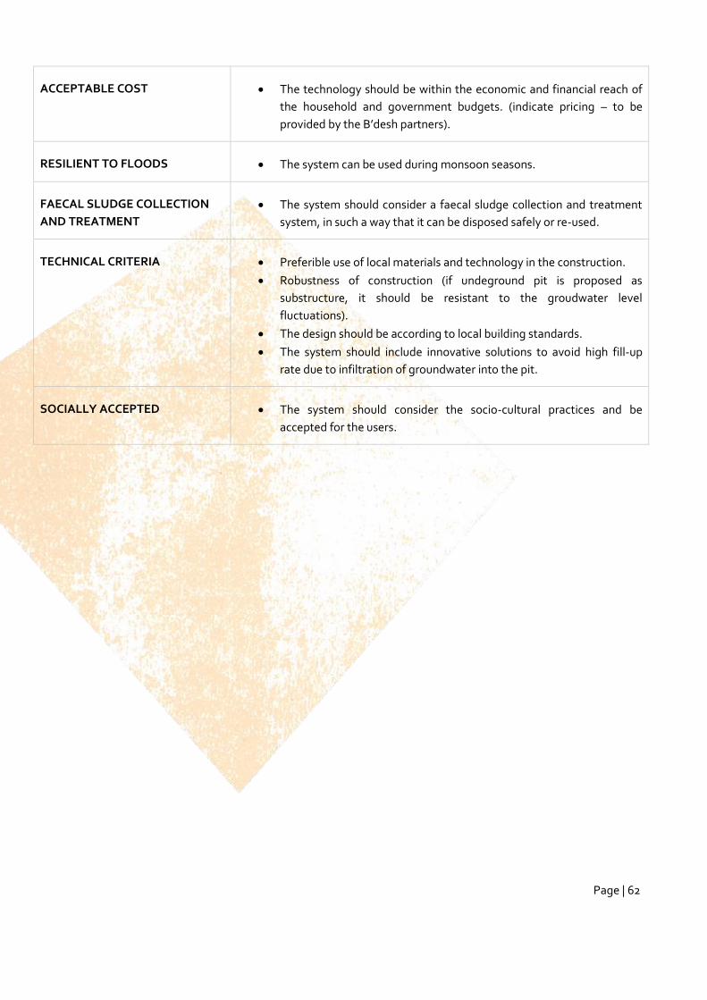
Page | 62
ACCEPTABLE COST The technology should be within the economic and financial reach of
the household and government budgets. (indicate pricing – to be
provided by the B’desh partners).
RESILIENT TO FLOODS The system can be used during monsoon seasons.
FAECAL SLUDGE COLLECTION
AND TREATMENT
The system should consider a faecal sludge collection and treatment
system, in such a way that it can be disposed safely or re-used.
TECHNICAL CRITERIA Preferible use of local materials and technology in the construction.
Robustness of construction (if undeground pit is proposed as
substructure, it should be resistant to the groudwater level
fluctuations).
The design should be according to local building standards.
The system should include innovative solutions to avoid high fill-up
rate due to infiltration of groundwater into the pit.
SOCIALLY ACCEPTED The system should consider the socio-cultural practices and be
accepted for the users.
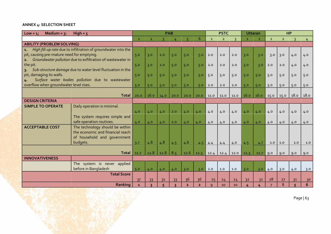
Page | 63
ANNEX 4: SELECTION SHEET
Low = 1; Medium = 3: High = 5 PAB PSTC Uttaran HP
1 2 3 4 5 6 1 2 3 1 2 1 2 3 4
ABILITY (PROBLEM SOLVING)
1. High fill-up rate due to infiltration of groundwater into the pit, causing pre-mature need for emptying.
5.0
3.0
2.0
5.0
5.0 5.0
2.0
2.0
2.0
3.0 3.0 3.0
3.0
4.0
4.0
2. Groundwater pollution due to exfiltration of wastewater in the pit.
5.0
3.0
2.0
5.0
5.0 5.0
2.0
2.0
2.0
3.0 3.0
2.0
2.0
4.0
4.0
3. Sub-structure damage due to water level fluctuation in the pit, damaging its walls.
5.0
5.0
5.0
5.0
5.0 5.0
5.0
5.0
5.0
5.0
5.0
5.0
5.0
5.0
5.0
4. Surface water bodies pollution due to wastewater overflow when groundwater level rises.
5.0
5.0
5.0
5.0
5.0 5.0
2.0
2.0
2.0
5.0
5.0
5.0
5.0
5.0
5.0
Total 20.0
16.0
14.0
20.0
20.0
20.0
11.0
11.0
11.0
16.0
16.0
15.0
15.0
18.0
18.0
DESIGN CRITERIA
SIMPLE TO OPERATE Daily operation is minimal. 4.0
4.0
4.0
2.0
4.0
4.0
4.0
4.0
4.0
4.0
4.0
4.0
4.0
4.0
4.0
The system requires simple and safe operation routines.
4.0
4.0
4.0
2.0
4.0
4.0
4.0
4.0
4.0
4.0
4.0
4.0
4.0
4.0
4.0
ACCEPTABLE COST The technology should be within the economic and financial reach of household and government budgets.
3.7
4.8
4.8
4.5
4.6 4.5
4.4
4.4
4.0
4.5 4.7 1.0
1.0 1.0 1.0
Total 11.7
12.8
12.8
8.5
12.6
12.5
12.4
12.4
12.0
12.5 12.7
9.0
9.0
9.0
9.0
INNOVATIVENESS
The system is never applied before in Bangladesh
5.0
4.0
4.0
4.0
3.0 3.0
2.0
1.0
1.0
3.0 3.0
4.0
3.0
4.0 3.0
Total Score 37
33
31
33
36
36 25
24
24
32 32
28
27
31 30
Ranking 1 3 5 3 2 2 9 10 10 4 4 7 8 5 6
Page | 64
ANNEX 5: INFORMATION ABOUT BIOGAS
BIOGAS
Biogas is a source of renewable energy, mainly constitutes methane (up to 80%) as the main or active
ingredient. It is also called marsh gas or swamp gas as it is naturally found (generated) in marshy areas. It is a
combustible gas and makes a good fuel. About 1.7 m3 of biogas is equivalent to a litre of petrol. Biogas
originates from bacteria in the process of bio-degradation of organic material under anaerobic (without air)
conditions. Methanogens (methane producing bacteria) degrade organic material and return the
decomposition products (manure) to the environment. Typical biogas composition is as follows:
Methane 50% - 75% Hydrogen 0% - 1%
Carbon Dioxide (CO2) 20% - 45% Hydrogen Sulphide (H2S) 0% - 3%
Nitrogen 0% - 10%
BIOGAS DIGESTERS
Biogas Digesters are completely sealed vessels which are covered and sealed (sometimes insulated and heated)
and convert human and animal waste into biogas (energy) and digested slurry (manure). A Biogas Digester
ferments human and animal waste (faeces and cow dung) through an anaerobic digestion process to produce
methane gas (biogas) and a viscous and fibrous slurry or digestate, which is an excellent manure and soil
conditioner, when used directly or after further decomposition with organic agricultural waste like crop
residues.
Domestic biogas plants convert livestock manure and night soil into biogas and slurry, the fermented manure.
Biogas can be used for cooking, lighting and even for running engines for motive power. The fermented manure
is a good soil conditioner which returns sizable plant nutrients back to the soil. This technology is feasible for
small holders with livestock producing 50 kg manure per day, an equivalent of about 6 pigs or 3 cows. This
manure is mixed with water and fed it into the plant. Agricultural and kitchen waste can be fed into the plant.
Toilets can be connected either directly to the digester or to the inlet pipe carrying cow dung. As the plant
operates at an optimum at 30°C - 40°C, the technology especially applies for those living in tropical and sub-
tropical climate. This makes the technology for small holders in developing countries often suitable. A typical
configuration is presented in the following diagram.
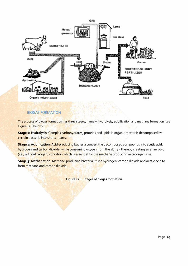
Page | 65
BIOGAS FORMATION
The process of biogas formation has three stages, namely, hydrolysis, acidification and methane formation (see
Figure 11.1 below).
Stage 1: Hydrolysis: Complex carbohydrates, proteins and lipids in organic matter is decomposed by
certain bacteria into shorter parts.
Stage 2: Acidification: Acid-producing bacteria convert the decomposed compounds into acetic acid,
hydrogen and carbon dioxide, while consuming oxygen from the slurry - thereby creating an anaerobic
(i.e., without oxygen) condition which is essential for the methane producing microorganisms.
Stage 3: Methanation: Methane-producing bacteria utilise hydrogen, carbon dioxide and acetic acid to
form methane and carbon dioxide.
Figure 11.1: Stages of biogas formation
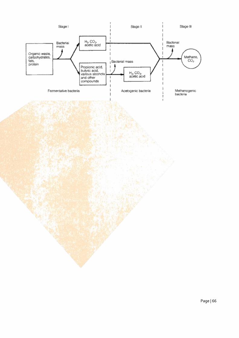
Page | 66
Page | 67
ANNEX 6: CALCULATION OF VOLUMES
1 Volumes dry feaces
The calculations are made for a family size of 6.
Basic Design Data and Assumptions
The following information and assumptions must be considered to estimate the size of the
collectors/vaults:
1. 6 months of storage duration after last use
2. Density of feaces assumed to be 1 kg/l
3. Volume of solid excreta per person per day 0.4 kg and 0.15 kg for adults and children/elderly, respectively
4. Account for absence
5. Toilet paper: no toilet paper used in Bangladesh.
6. Cover material assume daily average of 0.05 kg/p/y (e.g. ash)
7. 20% additional volume to account for void space
8. Volumetric reduction due to feacal dehydration is assumed to be 25%.
9. Single vault UDDTs with interchangeable containers are usually designed with space for at least two
containers at a time, in order to allow for short-term on-site storage of the faces
Calculation of required vault volume
The volume and dimensions of the dehydration vaults are determined by two factors: the volume of feacal
material deposited and the required storage time of the faces. The dimensions should also match with
the anticipated floor plan of the toilet cubicle above the vault
Step 1: Known information
St =Storage duration= 1 years (though 6 month is enough for dehydration and safe reuse if applied
Density of feaces = 1 kg/l
Toilet paper: (annual average of 8.9 kg/p/year) – assumed no toilet paper used in Bangladesh.
Cover material assume daily average of 0.05 kg/p/d (e.g. ash)
Ufa = Volume of solid excreta per adult per day = 0.4 kg
Ufce = Volume of solid excreta per child per day =0.15 kg
Na = Average number of adults per hh = 4 (2 parents and 2 grown up children)
Nce = Average number of children/elderly per hh = 2
Page | 68
Required:
Mf = Mass of feaces per hh per day,
Ma = mass of feaces per adults in a hh per day,
Mce = mass of feaces per children/elderly people per day
Mab = mass of feaces per hh per day
TMf = Total Mass of feaces per house per storage period
TMwl = Mass of Moisture loss during the storage period
TMai= Mass of additional inputs (toilet paper and cover material) during the storage period
VFe (effective volume of feaces production per storage period)
Vs= Volume required for safety purpose
TV = Total volume of vault for single vault systems
Volume of the vault?
Step 2: Production of faeces per day per family.
Mf= Ma + Mce
Ma = Na * Ufa
Mce = Nce * Ufce
Ma = Na * Ufa = 4 * 0.4 = 1.6 kg/day
Mce = Nce * Ufce = 2 * 0.15 = 0.3 kg/day
Mf = Ma + Mce = 1.6 +0.3 = 1.9 kg/day
Mf = 1.9 kg/day
Step 3: Added volume needed for breathing.
Mab = 20 % * Mf
Mab = 0.2 * 1.9 kg/day = 0.38 kg/day
Step 4: Production of faeces per year.
Page | 69
TMf = St*365days (Mf –Mab)
TMf = 1 year*364 days/year* (1.9 kg/day -0.38 kg/day)
TMf = 554 kg / year
Step 5:.
TMwl = 25 % * TMf
TMwl = 0.25 * 554 = 138 kg/year
Step 6:
TMai = (Mpy * St in years+ Mcd * St in days) * N
TMai = 0.05 kg/p/day* 365 day * 6
TMai = 18 * 6 = 108 kg/year
Step 7:.
VFe = (TMf-TMwl+TMai ) / density of feaces
VFe = (554 kg/ year – 138 kg/half year + 108 kg/ year) / 1kg/l
VFe = 524 l/ year
Step 8: Fill in the formula that you know the value of all the variables for.
Vs= 20% * VFe
Vs = 0.2 * 524
Safety margin = 104 L/ year
Step 9: Volume of production of dry faeces per year.
TV = (554+104) * 1 = 658 litres = 0.7 m3
Calculations to Determine Size of Urine Container
Basic Design Data and Assumptions
Page | 70
The following information and assumptions must be considered to estimate the size and emptying
frequency of the urine container:
1. Urine pipe size (1-2.5 cm)
2. Volume of urine = 1.1 L/p/day
3. N = Household size = 6
4. The urine piping system should ensure drainage with minimal odor and blockages.
short the pipe length, using larger diameter piping, minimizing the number of bends, ensuring sufficient slope and using no or minimal use of water for flushing.
Calculation of Required liquid volume (urine + wash water)
Total amount average urine produced per day per hh = volume of urine per person per day * N
Total daily urine volume = 1.1 L/p/d * 6 p =6.6 litres
Total daily wash-water volume = 2 * 6 = 12 litres
Total production per day: 18.6 litres / hh / day
References
1. GTZ UDDT technology review
Volumes unlined and lined pits
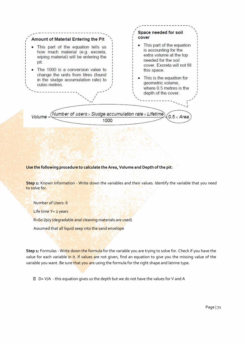
Page | 71
Use the following procedure to calculate the Area, Volume and Depth of the pit:
Step 1: Known information - Write down the variables and their values. Identify the variable that you need to solve for.
Number of Users: 6
Life time Y= 2 years
R=60 l/p/y (degradable anal cleaning materials are used)
Assumed that all liquid seep into the sand envelope
Step 1: Formulas - Write down the formula for the variable you are trying to solve for. Check if you have the
value for each variable in it. If values are not given, find an equation to give you the missing value of the
variable you want. Be sure that you are using the formula for the right shape and latrine type.
D= V/A - this equation gives us the depth but we do not have the values for V and A
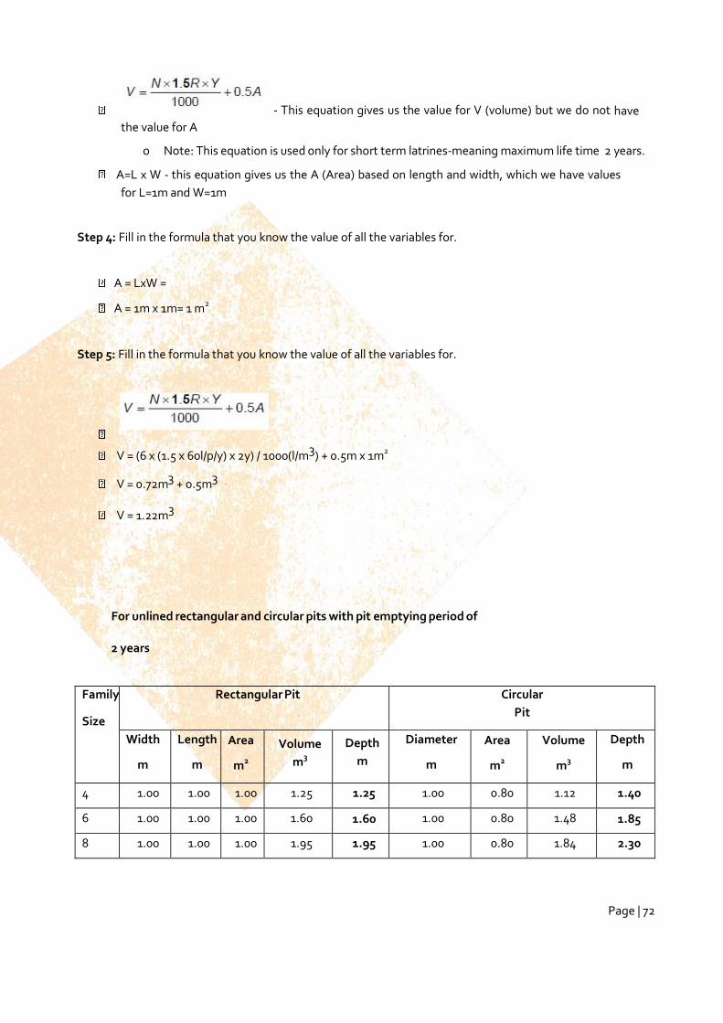
Page | 72
- This equation gives us the value for V (volume) but we do not have
the value for A
o Note: This equation is used only for short term latrines-meaning maximum life time 2 years.
A=L x W - this equation gives us the A (Area) based on length and width, which we have values
for L=1m and W=1m
Step 4: Fill in the formula that you know the value of all the variables for.
A = LxW =
A = 1m x 1m= 1 m2
Step 5: Fill in the formula that you know the value of all the variables for.
V = (6 x (1.5 x 60l/p/y) x 2y) / 1000(l/m3) + 0.5m x 1m2
V = 0.72m3 + 0.5m3
V = 1.22m3
For unlined rectangular and circular pits with pit emptying period of
2 years
Family
Size
Rectangular Pit Circular
Pit
Width
m
Length
m
Area
m2
Volume
m3
Depth
m
Diameter
m
Area
m2
Volume
m3
Depth
m
4 1.00 1.00 1.00 1.25 1.25 1.00 0.80 1.12 1.40
6 1.00 1.00 1.00 1.60 1.60 1.00 0.80 1.48 1.85
8 1.00 1.00 1.00 1.95 1.95 1.00 0.80 1.84 2.30
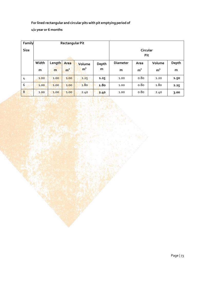
Page | 73
For lined rectangular and circular pits with pit emptying period of
1/2 year or 6 months
Family
Size
Rectangular Pit
Circular
Pit
Width
m
Length
m
Area
m2
Volume
m3
Depth
m
Diameter
m
Area
m2
Volume
m3
Depth
m
4 1.00 1.00 1.00 1.25 1.25 1.00 0.80 1.20 1.50
6 1.00 1.00 1.00 1.80 1.80 1.00 0.80 1.80 2.25
8 1.00 1.00 1.00 2.40 2.40 1.00 0.80 2.40 3.00

Page | 74
ANNEX 7: EARTHEN MOUND
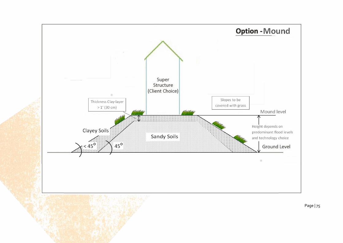
Page | 75
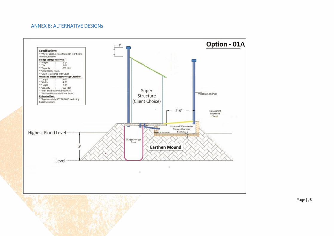
Page | 76
ANNEX 8: ALTERNATIVE DESIGNs

Page | 77
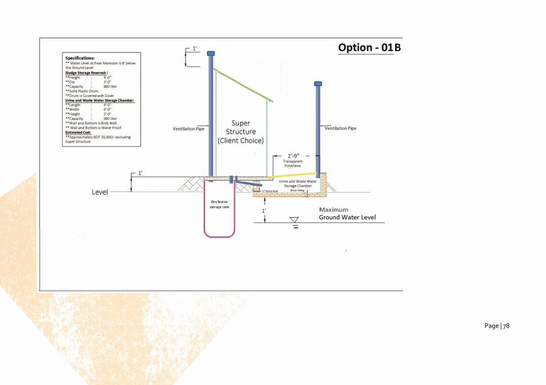
Page | 78
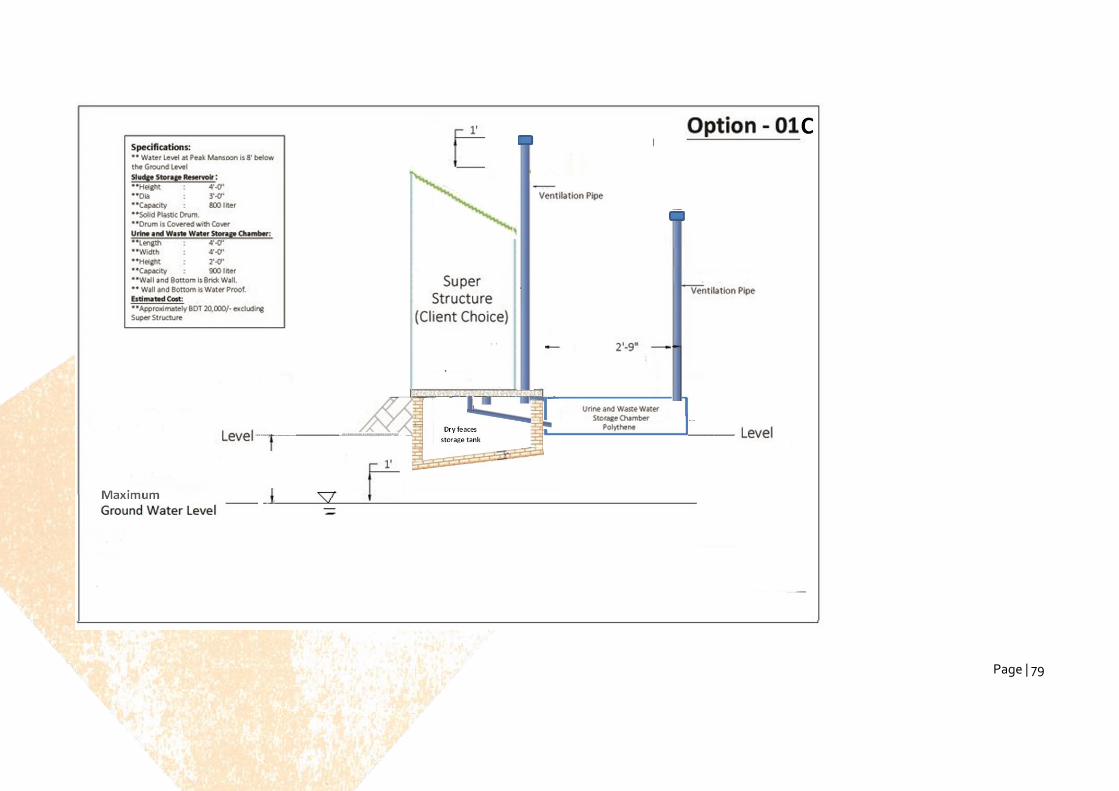
Page | 79

Page | 80
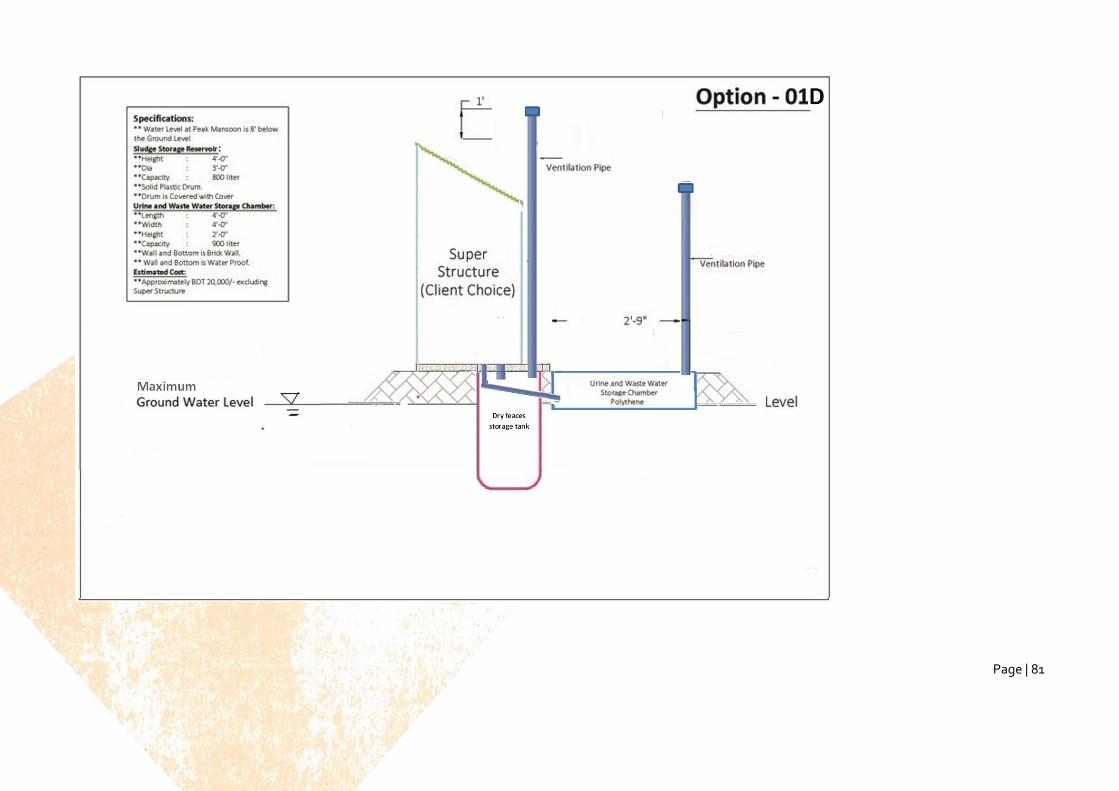
Page | 81
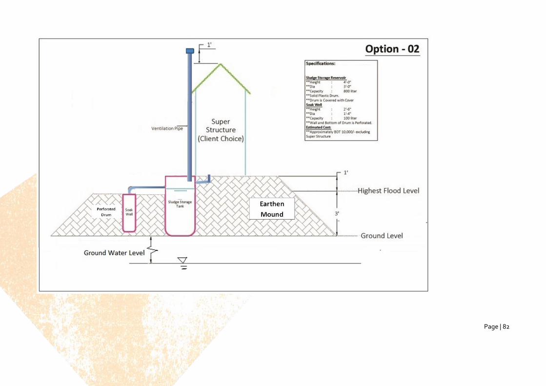
Page | 82
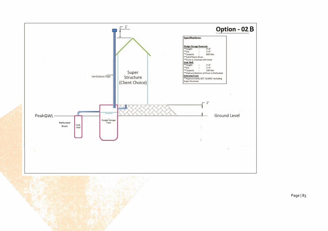
Page | 83
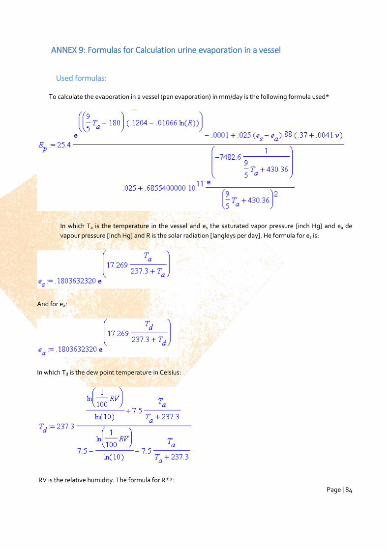
Page | 84
ANNEX 9: Formulas for Calculation urine evaporation in a vessel
Used formulas:
To calculate the evaporation in a vessel (pan evaporation) in mm/day is the following formula used*
In which Ta is the temperature in the vessel and es the saturated vapor pressure [inch Hg] and ea de
vapour pressure [inch Hg] and R is the solar radiation [langleys per day]. He formula for es is:
And for ea:
In which Td is the dew point temperature in Celsius:
RV is the relative humidity. The formula for R**:
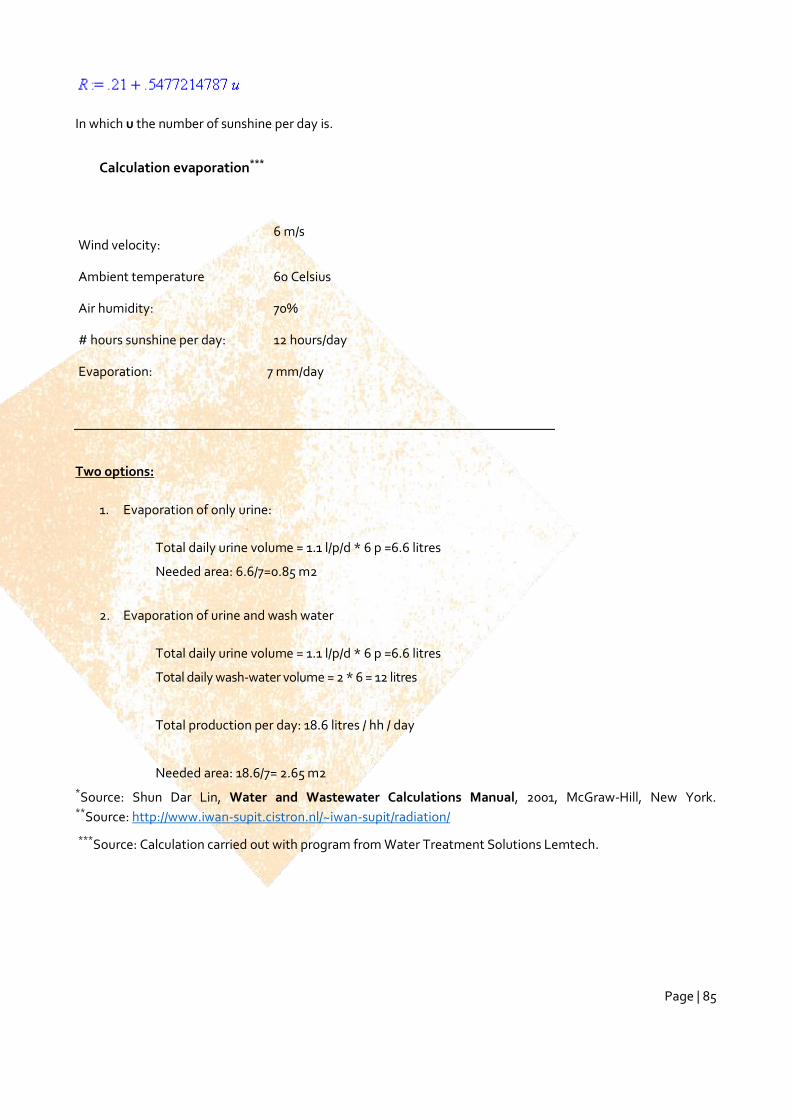
Page | 85
In which u the number of sunshine per day is.
Calculation evaporation***
Wind velocity: 6 m/s
Ambient temperature 60 Celsius
Air humidity: 70%
# hours sunshine per day: 12 hours/day
Evaporation: 7 mm/day
Two options:
1. Evaporation of only urine:
Total daily urine volume = 1.1 l/p/d * 6 p =6.6 litres
Needed area: 6.6/7=0.85 m2
2. Evaporation of urine and wash water
Total daily urine volume = 1.1 l/p/d * 6 p =6.6 litres
Total daily wash-water volume = 2 * 6 = 12 litres
Total production per day: 18.6 litres / hh / day
Needed area: 18.6/7= 2.65 m2
*Source: Shun Dar Lin, Water and Wastewater Calculations Manual, 2001, McGraw-Hill, New York. **Source: http://www.iwan-supit.cistron.nl/~iwan-supit/radiation/
***Source: Calculation carried out with program from Water Treatment Solutions Lemtech.
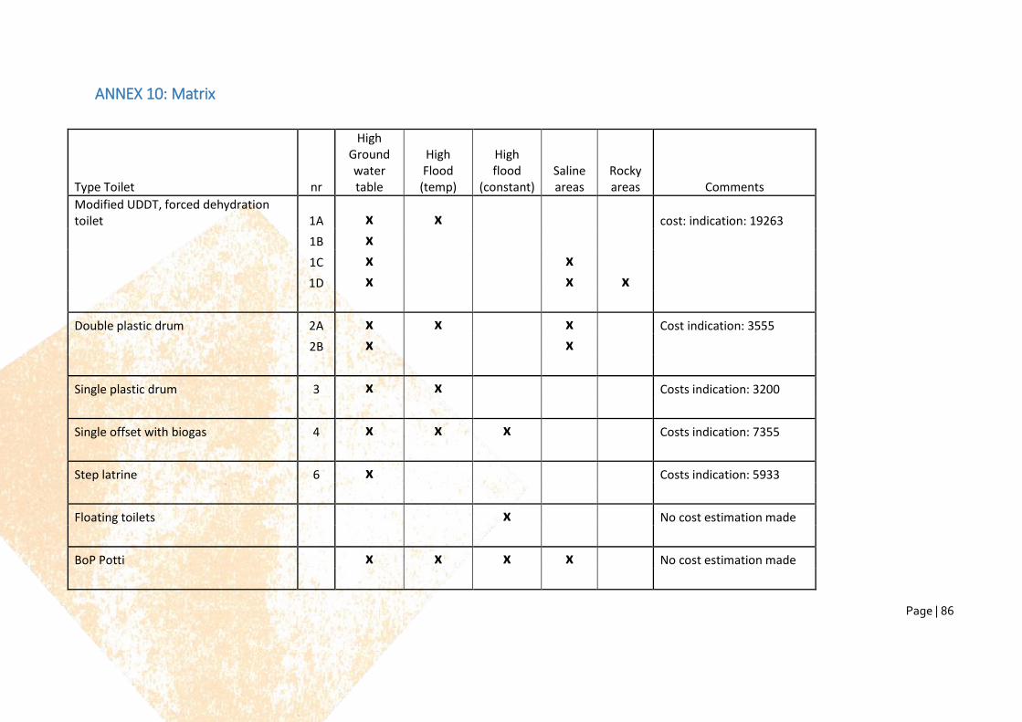
Page | 86
ANNEX 10: Matrix
Type Toilet nr
High Ground water table
High Flood
(temp)
High flood
(constant) Saline areas
Rocky areas Comments
Modified UDDT, forced dehydration toilet 1A x x
cost: indication: 19263
1B x
1C x
x
1D x
x x
Double plastic drum 2A x x x Cost indication: 3555
2B x
x
Single plastic drum 3 x x Costs indication: 3200
Single offset with biogas 4 x x x Costs indication: 7355
Step latrine 6 x Costs indication: 5933
Floating toilets x No cost estimation made
BoP Potti x x x x No cost estimation made
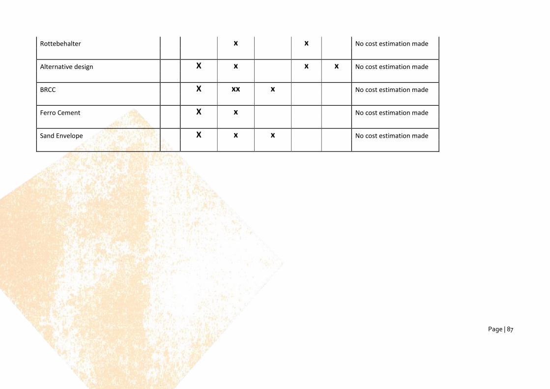
Page | 87
Rottebehalter x x No cost estimation made
Alternative design X x x x No cost estimation made
BRCC X xx x No cost estimation made
Ferro Cement X x No cost estimation made
Sand Envelope X x x No cost estimation made