Embed Size (px)
DESCRIPTION
use of sanders
Citation preview

OWNER’S MANUAL
B2022 - 25” DUAL DRUM SANDER
INDEX GENERAL SAFETY INSTRUCTIONS Page 3 Specifications Page 4 Features Page 5 Assembly Instructions Initial Assembly Page 6 Installing Abrasives Page 7 Adjusting Drum Rollers Page 8-9 Hold Down Roller Adjustment Page 10 Maintenance Page 10 Drive Belt Adjustment & Replacement Page 11 Lubrication Page 11 Wiring Diagram Page 12 Schematic Diagrams Page 13-16 Parts Breakdown Page 17-22 Warranty Page 23
2
GENERAL SAFETY INSTRUCTIONS EXTREME CAUTION SHOULD BE USED IN OPERATING ALL POWER TOOLS. KNOW
YOUR POWER TOOL, BE FAMILIAR WITH ITS OPERATION. READ THE OWNER’S
MANUAL AND PRACTICE SAFE USAGE PROCEDURES AT ALL TIMES.
CONNECT your machine ONLY to the matched and specified power source.
WEAR SAFETY GLASSES, RESPIRATORS, HEARING PROTECTION
and SAFETY SHOES when operating heavy machinery. Always wear safety
glasses.
DO NOT wear loose clothing or jewellery when operating machinery.
A Safe Environment is important. Keep the area free of dust, dirt and other
debris in the immediate vicinity of the machine.
BE ALERT! Do Not Use prescription or other drugs that may affect your ability
or judgement to safely use this machine.
DISCONNECT the power source when changing abrasive paper.
NEVER leave an operating tool unattended.
NEVER reach over the table when the tool is in operation.
ALWAYS keep all safety guards in place and ensure their proper function.
ALWAYS use push sticks and featherboards to safely feed your work through the
machine.
ALWAYS make sure that any tools used for adjustments are removed before
operating the machine.
ALWAYS secure your work with the appropriate clamps or vises.
ALWAYS keep bystanders safely away while operating machinery.
THINK SAFETY. WORK SAFELY. Never attempt a procedure if it does not
feel safe or comfortable.
3
B2022 - 25” DUAL DRUM SANDER
SPECIFICATIONS As part of the growing line of Craftex woodworking equipment, we are proud to offer the B2022 Dual Drum Sander. The Craftex name guarantees Craft Excellence. By following the instructions and procedures laid out in this owner’s manual, you will receive years of excellent service and satisfaction. The B2022 is a professional tool and like all power tools, proper care and safety procedures should be adhered to. Main Motor - 3HP, 220V, 1 Phase Drive Belt Motor - 1/4HP, 220V, 1 Phase Drum Diameter - 6” (Twin Rubber Coated) Hold Down Roller Diameter - 1 ½” Maximum Sanding Width - 25” Maximum Depth Per Pass - 1/64” Minimum Material Thickness - ¼” Maximum Material Thickness - 6” Minimum Material Length - 9” Conveyor Belt Speed (2) Speeds – 11 FPM, 17 FPM Sanding Drum Speed – 2,500 FPM Dust Collection Ports – 2 @ 4” Minimum Dust Collection CFM – 1,100 CFM All Sealed Ball Bearings Approx. Shipping Weight – 625 LBS
4
B2022 - 25” DUAL DRUM SANDER
FEATURES With a full 25” sanding capacity, the B2022 features twin rubber coated steel drums that isolate the drums from heat build up. The drums feature an exclusive spring-loaded adjuster to keep constant belt tension & a mechanical fastener at each end of the drum for fast attachment of your adhesive paper. Three rubber hold down rollers hold material firmly against the cast iron work table with a built in thickness gauge. Heavy duty welded pieces stand with a hinged lid for quick access to the sanding drums. The adjustable table extension rollers help to eliminate snipe & the 2-speed conveyor belt operates in both forward & reverse directions at either 11FPM or 17 FPM. NOTE: THE B2022 IS DESIGNED TO BE USED AS A FINISH SANDER AND NOT AS A SURFACE PLANER. Never increase the sanding depth by more than ¼ turn of the handle or increase the depth of cut when sanding in the reverse direction of feed.
5
B2022 - 25” DUAL DRUM SANDER
ASSEMBLY INSTRUCTIONS
1) Remove the unit from the shipping crate. There are four bolts holding the unit
to the shipping crate. These can be removed through the motor access door. 2) Install the reversing switch to the right side of the sander by removing the
screw in the reversing switch cover and using two Phillip’s Head screws, attach the switch and the two ground wires to the right side of the sander. Then re-install the cover on the switch and tighten the cover screw.
3) Remove the 4 eyebolts in the hinged cover. Raise the cover and install the 2 – 4” dust hoods with the screws and nuts provided.
4) Attach the proper plug to the power cable. The red wire and black wire are the hot leads. The green wire is used for neutral & ground. This unit must be connected only to a properly grounded 30 AMP, 220V dedicated circuit. If you have any questions about properly making the wiring connections, we recommend you contact a qualified electrician.
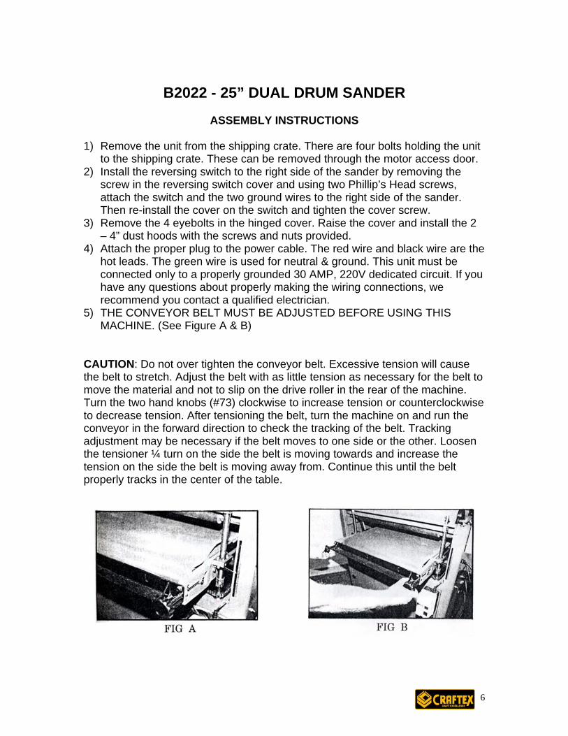
5) THE CONVEYOR BELT MUST BE ADJUSTED BEFORE USING THIS MACHINE. (See Figure A & B)
CAUTION: Do not over tighten the conveyor belt. Excessive tension will cause the belt to stretch. Adjust the belt with as little tension as necessary for the belt to move the material and not to slip on the drive roller in the rear of the machine. Turn the two hand knobs (#73) clockwise to increase tension or counterclockwise to decrease tension. After tensioning the belt, turn the machine on and run the conveyor in the forward direction to check the tracking of the belt. Tracking adjustment may be necessary if the belt moves to one side or the other. Loosen the tensioner ¼ turn on the side the belt is moving towards and increase the tension on the side the belt is moving away from. Continue this until the belt properly tracks in the center of the table.
6
B2022 - 25” DUAL DRUM SANDER
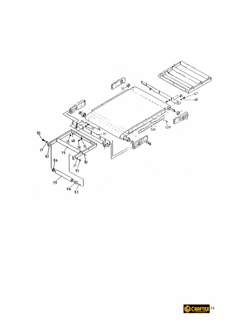
ASSEMBLY cont… INSTALLING ABRASIVES CAUTION: Disconnect the machine from the power source for installation or removal of abrasive paper. To install the abrasive paper, remove the four eye bolts and raise the drum cover. Remove the old paper by removing the Allen bolt #30 and the wedge #29 on the right of the drum. Remove the balance of the paper working your way to the left side. The left side is under spring pressure. When you have to come to the left side of the drum, release the paper and hold the drum to release the spring pressure. Next, remove the Allen bolt and the wedge from the left side.
Save the paper you just removed to use as a pattern to cut the new abrasive with.
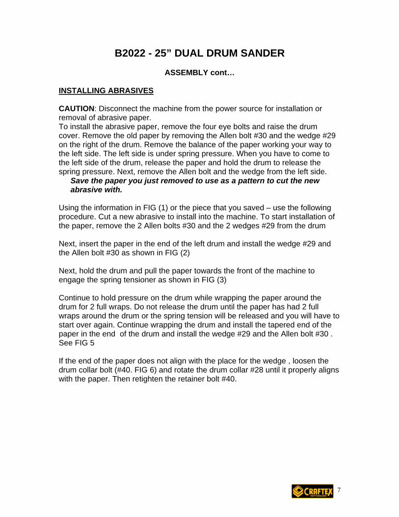
Using the information in FIG (1) or the piece that you saved – use the following procedure. Cut a new abrasive to install into the machine. To start installation of the paper, remove the 2 Allen bolts #30 and the 2 wedges #29 from the drum Next, insert the paper in the end of the left drum and install the wedge #29 and the Allen bolt #30 as shown in FIG (2)
Next, hold the drum and pull the paper towards the front of the machine to engage the spring tensioner as shown in FIG (3)
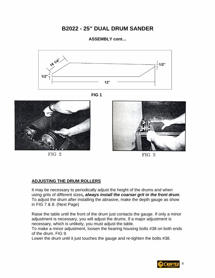
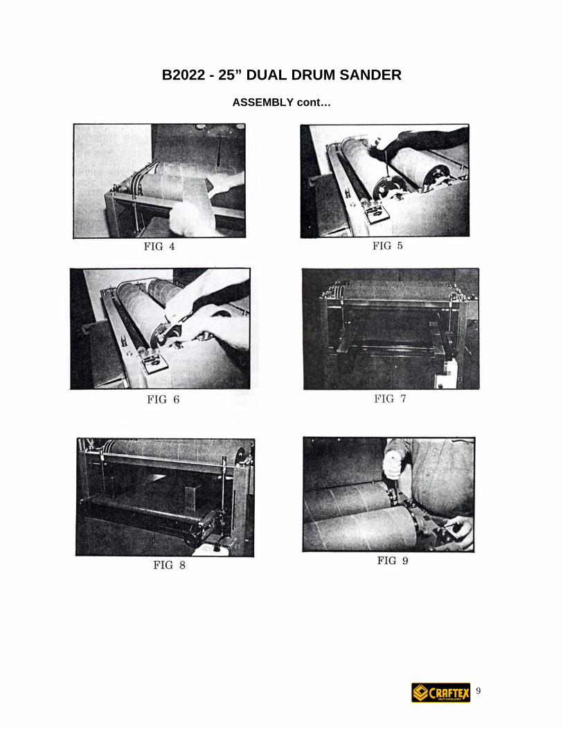
Continue to hold pressure on the drum while wrapping the paper around the drum for 2 full wraps. Do not release the drum until the paper has had 2 full wraps around the drum or the spring tension will be released and you will have to start over again. Continue wrapping the drum and install the tapered end of the paper in the end of the drum and install the wedge #29 and the Allen bolt #30 . See FIG 5
If the end of the paper does not align with the place for the wedge , loosen the drum collar bolt (#40. FIG 6) and rotate the drum collar #28 until it properly aligns with the paper. Then retighten the retainer bolt #40.
7
B2022 - 25” DUAL DRUM SANDER
ASSEMBLY cont…
1
ADJUSTING THE DRUM ROL It may be necessary to periodicusing grits of different sizes, alwTo adjust the drum after installiin FIG 7 & 8. (Next Page) Raise the table until the front ofadjustment is necessary, you wnecessary, which is unlikely, yoTo make a minor adjustment, loof the drum. FIG 9. Lower the drum until it just touc
FIG
LERS
ally adjust the height of the drums and when ays install the coarser grit in the front drum.
ng the abrasive, make the depth gauge as show
the drum just contacts the gauge. If only a minor ill adjust the drums. If a major adjustment is u must adjust the table. osen the bearing housing bolts #38 on both ends
hes the gauge and re-tighten the bolts #38.
8
B2022 - 25” DUAL DRUM SANDER
ASSEMBLY cont…
9
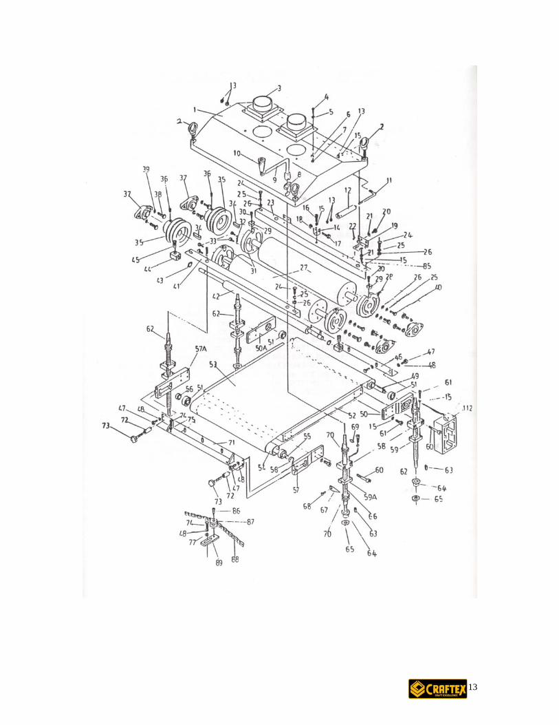
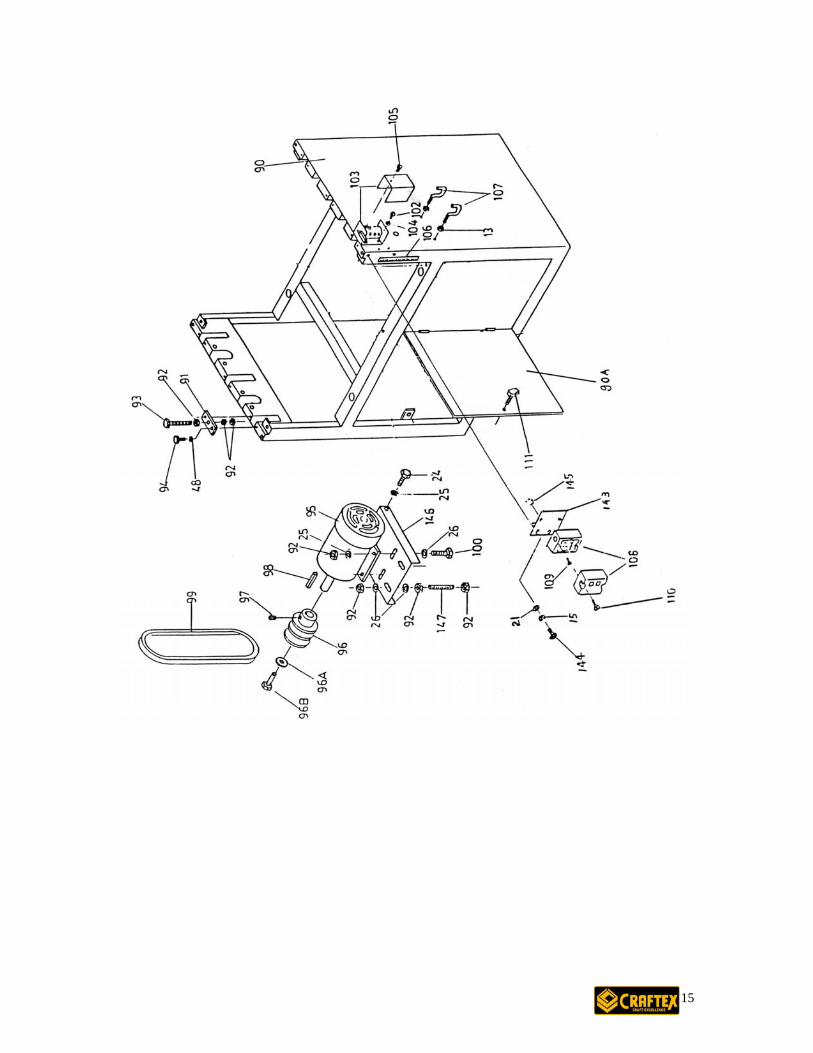
B2022 - 25” DUAL DRUM SANDER WHEN RE-INSTALLING THE SAME GRIT ON BOTH DRUMS, YOU MUST RE-ADJUST THE DRUM HEIGHT. To make a major adjustment to the table requires the use of both depth gauges. Place the gauges under the drums near the outside edges of the table as shown in FIG 10. Raise the table until contact is made between the drums and the gauges. If both drums do not touch the gauges, the table must be adjusted. To adjust the tables, loosen the chain adjuster bolt #74 & remove the chain #88 from all 4 sprockets #64. FIG 11 Next, insert a screwdriver or similar tool in the hole in the top post #62, FIG 10. At the corner of the table that is lowest, turn clockwise to raise the table until the drum contacts the gauge. Do this for each post until even contact is made with the gauge. Re-install the chain #88 on all 4-corner posts and install the chain adjuster so that there is approx. 1/8”deflection in the chain between the front corner posts & the tensioner. Next, lower the table until the gauges can be removed. Now you must adjust each of the 3 hold down rollers.
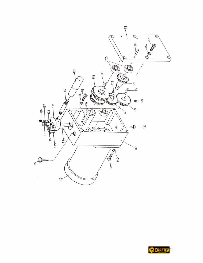
HOLD DOWN ROLLER ADJUSTMENT Hold down rollers will need adjustment if the material cannot be fed under the drums or when the finished surface is uneven. To adjust the rollers, loosen the roller pressure or raise the bolt to decrease the pressure. Do not over tighten the bolt as excessive down pressure will not allow material under the rollers or the conveyor belt can be stopped. MAINTANENCE About once a week, check the oil level in the gearbox. If the oil is visible in the eyeglass on the side of the gearbox, the oil is at the proper level. To add oil to the gearbox, remove the Allen bolt #136, spring #137 and ball #138. Remove the Allen bolt #86. Remove the shifter assembly and add the proper amount of machine oil. After, re-install the assembly with the shaft #134 between gears of #118. Install bolt #86 and the ball #138, spring #137 and set screw #136. The gearbox will operate at 11 FPM or 17 FPM in either direction. The gearbox speed can only be changed when the conveyor belt is moving. The conveyor belt on the sander can be used in both a forward & reverse direction. The drums rotate in only one direction. CAUTION: When changing the direction of the belt travel, allow the conveyor belt to completely stop before changing the direction of travel.
10
B2022 - 25” DUAL DRUM SANDER
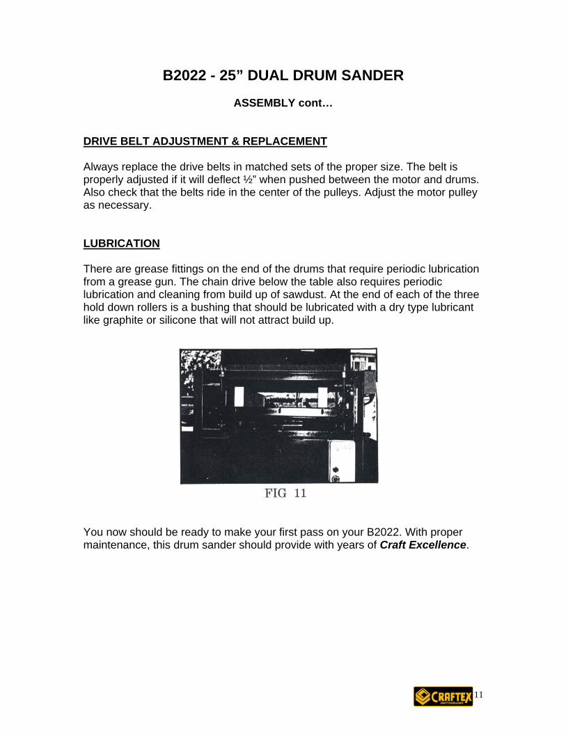
ASSEMBLY cont… DRIVE BELT ADJUSTMENT & REPLACEMENT Always replace the drive belts in matched sets of the proper size. The belt is properly adjusted if it will deflect ½” when pushed between the motor and drums. Also check that the belts ride in the center of the pulleys. Adjust the motor pulley as necessary. LUBRICATION There are grease fittings on the end of the drums that require periodic lubrication from a grease gun. The chain drive below the table also requires periodic lubrication and cleaning from build up of sawdust. At the end of each of the three hold down rollers is a bushing that should be lubricated with a dry type lubricant like graphite or silicone that will not attract build up.
You now should be ready to make your first pass on your B2022. With proper maintenance, this drum sander should provide with years of Craft Excellence.
11
B2022 - 25” DUAL DRUM SANDER
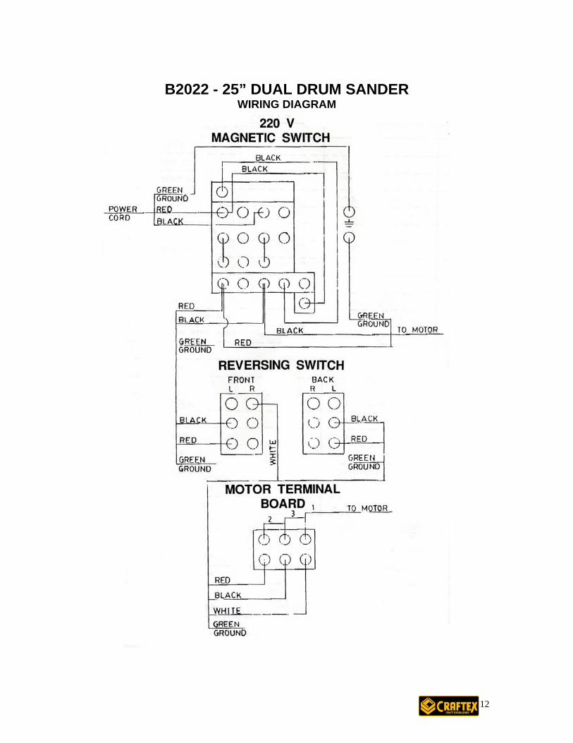
WIRING DIAGRAM
12
13
14
15
16
17
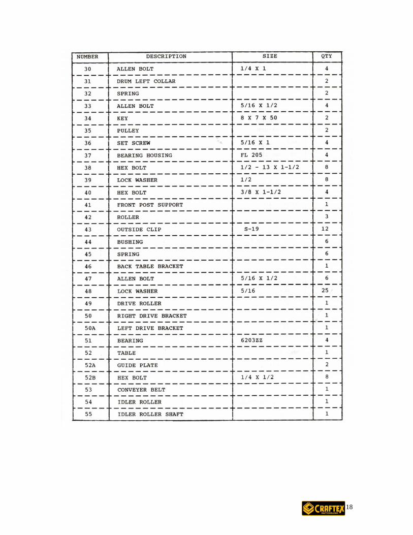
18
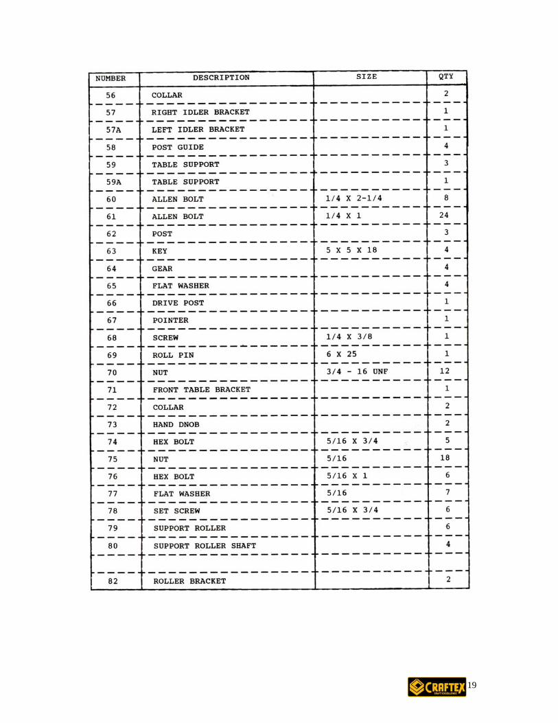
19
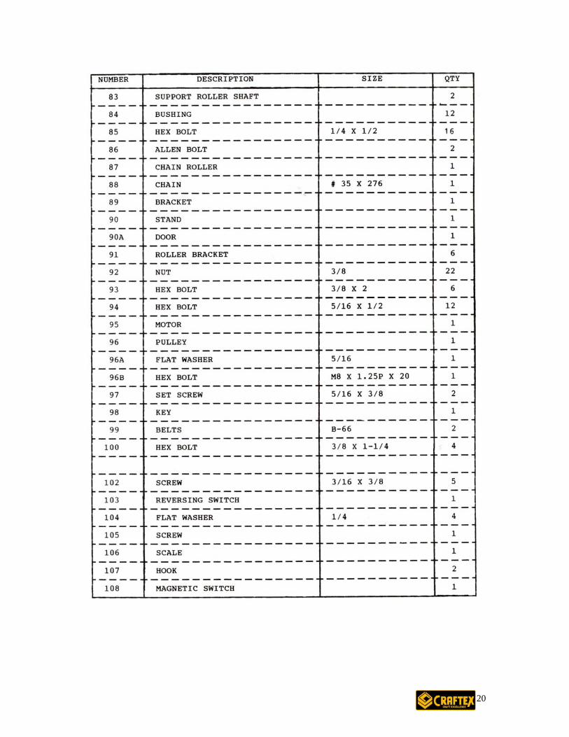
20
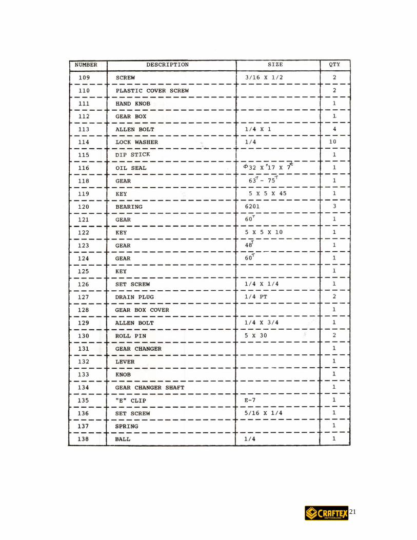
21
22

WARRANTY Y Craftex warrants everyThis warranty covers tfrom the date of purchainstallation or assemblProof of purchase is neAll warranty claims areto inspect any returnedThis warranty shall notCraftex shall in no eveproperty or for incidenproducts.
R To return, repair, or rep461-BUSY. Craftex is For replacement parts dyour credit card and pa• All returned merch
following qualifica• Returns must be p• We do not accept • Items returned for• Returns must be ac
used condition andshipping and hand
• Busy Bee will repa• Repaired or replac• Busy Bee reserves
authorization has c• Repairs made by B• Any unforeseen re• The Busy Bee Par
the exception of sowill provide you w
• For faster service iproduct in for repa
CRAFTEX 2 YEAR LIMITED WARRANT
product to be free from defects in materials and agrees to correct such defects where applicable. wo years for parts and 90 days for labour (unless specified otherwise), to the original purchaser se but does not apply to malfunctions arising directly or indirectly from misuse, abuse, improper
y, negligence, accidents, repairs or alterations or lack of maintenance. cessary. subject to inspection of such products or part thereof and Craftex reserves the right
item before a refund or replacement may be issued. apply to consumable products such as blades, bits, belts, cutters, chisels, punches etceteras. nt be liable for injuries, accidental or otherwise, death to persons or damage to tal contingent, special or consequential damages arising from the use of our
ETURNS, REPAIRS AND REPLACEMENTS
lace a Craftex product, you must visit the appropriate Busy Bee Tools showroom or call 1-800-a brand of equipment that is exclusive to Busy Bee Tools. irectly from Busy Bee Tools, for this machine, please call 1-800-461-BUSY (2879), and have rt number handy. andise will be subject to a minimum charge of 15% for re-stocking and handling with the tions.
re-authorized by us in writing. collect shipments. warranty purposes must be insured and shipped pre-paid to the nearest warehouse companied with a copy of your original invoice as proof of purchase. Returns must be in an un- shipped in their original packaging a letter explaining your reason for the return. Incurred ling charges are not refundable. ir or replace the item at our discretion and subject to our inspection. ed items will be returned to you pre-paid by our choice of carriers. the right to refuse reimbursement or repairs or replacement if a third party without our prior arried out repairs to the item. usy Bee are warranted for 30 days on parts and labour.
pair charges will be reported to you for acceptance prior to making the repairs. ts & Service Departments are fully equipped to do repairs on all products purchased from us with me products that require the return to their authorized repair depots. A Busy Bee representative ith the necessary information to have this done. t is advisable to contact the nearest Busy Bee location for parts availability prior to bringing your irs.
23

24

25

26