Embed Size (px)
Citation preview
SAN JOSE CITY COLLEGE PROJECT NO:Stadium Audiovisual Upgrades Addendum 1 – March 6, 2017
February 14, 2017 274116 - 1 Integrated Audiovisual Systemsand Equipment
SECTION 27 41 16
INTEGRATED AUDIOVISUAL SYSTEMS AND EQUIPMENT
PART 1 - GENERAL
1.1 SECTION INCLUDES
A. Provide all labor, materials, transportation and equipment to complete the furnishing, installation,assembly, set up, and testing of the Sound and Audiovisual System work indicated on the drawingsand specified herein. Notwithstanding any detailed information in this Section, provide complete,working systems.
B. Design, engineer and provide complete, all means of support, suspension, attachment, fastening,bracing, and restraint (hereinafter "support") of the Work of this Section. Provide engineering of suchsupport by parties licensed to perform work of this type in the Project jurisdiction.
1.2 STADIUM AUDIOVISUAL SYSTEMS AND EQUIPMENT
A. Provide the following, in addition to work shown on the drawings, along with any additionalequipment and accessories required for a complete, working system:
B. Provide and install (N) Audiovisual, DSP, and control systems and equipment in SJCC StadiumClubhouse Announcer’s Booth. Re-use and relocate existing equipment as indicated. Removeexisting audiovisual equipment rack and install new swing-out type audiovisual equipment rack.
C. Provide and install new loudspeakers, loudspeaker enclosures and mounts, assistive listeningequipment, cabling, and conduit to new locations on Home Bleachers and Visitor Bleachers.Commission, aim, test, and verify maximum sound pressure levels of installed devices.
D. AS A BID ALTERNATE Provide and install new loudspeakers, loudspeaker enclosures and mounts,assistive listening equipment, cabling, and conduit to new locations on Overflow Bleachers.Commission, aim, test, and verify maximum sound pressure levels of installed devices usingtemporary connection between AV system in Announcer’s Booth and Overflow loudspeakers(underground pathway for permanent connection will be work of future project).
E. AS A BID ALTERNATE provide cabling and conduit from Announcer’s Booth audiovisual rack tonew junction box at north rear corner of Home Bleachers adjacent to existing telephone backboardfor future connection to Overflow bleachers system.
F. AS A BID ALTERNATE provide cabling and conduit from Overflow loudspeaker locations to newjunction box at east rear corner of Overflow Bleachers adjacent for future connection to Overflowbleachers system.
G. Develop user interface for control systems with Owner Representatives familiar with the operation ofAssemblies, Performances, and other Events within the Auditorium. Provide system programming,training, and support to Owner during first-substantial-use of (N) systems and equipment.
H. Loudspeaker/Audio Processing, general:1. Program audio and speech content to output through overhead loudspeakers.
I. Racking compartment, general:1. Provide blank plates at all unused openings.2. Provide fans as required to keep the interior of each equipment rack at a temperature at least 5-
10 degrees cooler than equipment manufacturer’s recommended operating temperature.a. Fans to emit not more than 30 dB of noise.
J. Control Systems, general:
SAN JOSE CITY COLLEGE PROJECT NO:Stadium Audiovisual Upgrades Addendum 1 – March 6, 2017
February 14, 2017 274116 - 2 Integrated Audiovisual Systemsand Equipment
1. Review all push button and touch panel button nomenclature with Owner Representative prior tosystem programming.
2. Provide graphic indication of program volume level on control touch panel when volume control Is selected.
3. Provide Main Menu selection button on all touch panel screens to route user back to main touchpanel menu.
K. Control Functions:1. Control: Confirm all control functions and layouts with Owner Representative prior to system
programming.2. Control Button Panel (Existing)
a. General: Functions to operate by scene/mode, not by device.b. End user selection of a single A/V input source (push buttons) automates:
i. Presets recalled.ii. Sets audio chain to loudspeakers.
c. End user selection on an Audio Only input automates:i. Sets audio chain.
d. Touch Panel Menus:i. Startup Page: “Press here to Begin”ii. Home Page:
(1) “Select Source”: provides sub-menus of source selections.(2) “Power Off”: Provides sub-menu selection of “Do you want to power off the
system?” with “Yes” and “No” selections. Upon selection of “Yes”, menu reads“Please wait, shutting down system.”
iii. All menus, except Home Page, to include “Home” button to revert back to HomePage.
1.3 REFERENCE STANDARDS
A. Conform to the applicable portions of the current standards published by these organizations:1. SMPTE Society of Motion Picture and Television Engineers.2. NAB National Association of Broadcasters.3. EIA Electrical Industries Association of America.4. UL Underwriters Laboratories.5. AES Audio Engineering Society.6. NEC National Electrical Code.7. UBC Uniform Building Code.8. NFPA National Fire Protection Association.9. EIAJ Electrical Industries Association of Japan.10. IEC International Electrotechnical Commission.11. FCC Federal Communications Commission.12. NTC Network Transmission Committee of the Video Transmission
Engineering Advisory Committee.13. NCTA National Cable Television Association.14. BTSC Broadcast Television Stereo Committee.15. TASO Television Allocation Study Organization.
B. Conform additionally to the following specific standards:1. American National Standards Institute (ANSI)
a. ANSI S1.4-1983 (R2001) American National Standard Specification for Sound LevelMeters
b. ANSI S1.11-1986 (R2001) American National Standard Specification for Octave-Band andFractional Octave-Band Analog and Digital Filters
c. ANSI S1.42-1986 (R2001) American National Standard Design Response of WeightingNetworks for Acoustical Measurements
d. ANSI IT 7.214-89 Audio-visual Systems - Front Projection Screens (Tripod/Free-Standing)- Methods for Testing and Reporting Performance Characteristics.

SAN JOSE CITY COLLEGE PROJECT NO:Stadium Audiovisual Upgrades Addendum 1 – March 6, 2017
February 14, 2017 274116 - 3 Integrated Audiovisual Systemsand Equipment
2. Audio Engineering Society Incorporated (AES)a. AES2-1984 (r1997) AES Recommended Practice Specification of Loudspeaker
Components Used in Professional Audio and Sound Reinforcementb. AES5-1998 (Revision of AES5-1984) AER recommended practice for professional digital
audio – Preferred sampling frequencies for applications employing pulse-code modulationc. AES14-1992 (r1998) AES standard for professional audio equipment – Application of
connectors, part 1, XLR-type polarity and genderd. AES20-1996 AES recommended practice for professional audio – Subjective evaluation of
loudspeakerse. AES26-2001 Revision of AES26-1995 AES recommended practice for professional audio
interconnections – Conservation of the polarity of audio signalsf. AES-R2-1998 AES project report for articles on professional audio and for equipment
specifications – Notations for expressing levels3. Electronic Industries Association of America (EIA)
a. EIA-160 Sound Systemsb. EIA-310-E Racks, Panels and Associated Equipmentc. EIA-101-A Amplifiers for Sound Equipmentd. SE-103 Speakers for Sound Equipmente. SE-104 Engineering Specifications for Amplifiers for Sound Equipment
4. International Electrotechnical Commission (IEC)a. IEC 268-3 (1988) Sound system equipment – Part 3: Amplifiersb. IEC 268-5 (1989) Sound system equipment – Part 5: Loudspeakersc. IEC 268-12 (1987) Sound system equipment – Part 12: Application of Connectors for
Broadcast and Similar Used. IEC 651 (1979) Sound level meters
5. International Organization for Standardization (ISO)a. ISO 1996-1 Acoustics – Description and measurement of environmental noise – Part 1:
Basic quantities and – Composite Analog Video Signal – NTSC for Studio Applications6. Federal Specifications (FS)
a. GG-S-00172D Screen, Projection. Federal Supply Classification (FSC) 670.7. Federal Standards (Fed-Std)
a. 191A Textile Test Methods.i. 5760 Mildew Resistance of Textile Materials; Mixed Culture Method.ii. 5903.1 Flame Resistance of Cloth; Vertical.
8. NFPAa. 255 Method of Testing Surface Burning Characteristics of Building Materials.b. 701 Methods of Fire Tests for Flame-Resistant Textiles and Films.
9. Society of Motion Picture Engineers (SMPTE).a. SMPT 196M-86 Motion Picture - Screen Luminance and Viewing Conditions - Indoor
Theater Projection Guide.b. SMPTE 202M-1998 Motion Pictures – B Chain Electroacoustic Response – Dubbing
Theaters, Review Rooms and Indoor Theatersc. SMPTE RP167-1995 Alignment of NTSC Color Picture Monitorsd. SMPTE EG1-1990 Alignment Color Bar Test Signal for Television Picture Monitorse. SMPTE EG27-1994 Supplemental Information for ANSI/SMPTE 170M and Background on
the Development of NTSC Color Standards (R1999)f. RP 94 Recommended Practice for Gain Determination of Front Projection Screens.g. SMPTE RP 95 Recommended Practice for Installation of Gain Screens.h. SMPTE RP 98 Recommended Practice for Measurement of Screen Luminance in
Theatres.10. Underwriters Laboratories Incorporated (UL)
a. UL 813 Commercial Audio Equipment 1996b. UL 1419 Professional Video and Audio Equipment 1997c. UL 1492 Audio-Video products and Accessories 1996d. UL 6500 Audio/Video and Musical Instrument Apparatus for Household, Commercial and
Similar General Use 19991.4 RELATED WORK IN OTHER SECTIONS
SAN JOSE CITY COLLEGE PROJECT NO:Stadium Audiovisual Upgrades Addendum 1 – March 6, 2017
February 14, 2017 274116 - 4 Integrated Audiovisual Systemsand Equipment
A. Section 27 41 01 – Grounding and Bonding for Audiovisual Systems
B. Section 27 41 02 – Hangers and Supports for Audiovisual Systems
C. Section 27 41 03 – Conduits and Backboxes for Audiovisual Systems1. Raceway system for work of this Project, including floorboxes.
D. Section 27 41 06 – Noise and Vibration Controls for Audiovisual Systems1. Outlet box pads for the work of this Project.
E. Section 27 41 07 – Identification for Audiovisual Systems
F. Section 27 41 08 – Audiovisual Cabinets, Racks, Frames1. Floor Mounted and Casework Equipment Racks for the work of this Section.
G. Section 27 41 09 – Audiovisual Cable Management1.5 QUALITY ASSURANCE
A. Test Equipment - Refer to 27 41 00:1. Sound Systems:
a. Wide band oscilloscope, 50 MHz, analog. (Example: Tektronix TAS-250 or 2212).b. True RMS audio digital volt-ohm-millimeter (Example: Fluke 8060A).c. Integrated audio test set (Example: Audio Precision or Neutrik A1 or A2 System).d. Acoustic polarity tester (Example: BSS Audio Ltd. Phasecheck System AR 130).e. Pink Noise generator (Example: Ivie IE-20B).f. Calibrated microphone and pre-amplifier assembly (Example: Ivie IE-2P
preamplifier/power supply with Ivie/ACCO, Bruel & Kjaer, or Larson-Davis microphonecapsule).
g. Real time audio spectrum analyzer, one-third octave (Example: Ivie IE-30A or JBL Smaartsystem).
h. Frequency/time audio analyzer (Example: Crown TEF system or JBL Smaart system).
B. Baseband Video Systems:1. Wide band oscilloscope, 50 MHz, analog. (Example: Tektronix TAS-250 or 2212).2. Analog composite test generator (Example: Tektronix TSG 170A or TSG 100 Opt. 01).3. Analog composite waveform/vector monitor (Example: Tektronix 1740A or WFM 90.)
C. RGBHV Wideband Component Analog Video Systems:1. Wide band oscilloscope, 200 MHz, analog. (Example: Tektronix TAS-485).2. RGBHV test generator (Example: Extron VTG 100).
D. Projection Systems:1. Luminance meter. (Example: Tektronix J17/J18 with J1803 8 degree luminance head.).2. Grey scale chart.3. Precision optical comparator. (Example: Phillips or Tektronix J17/J18 with J1810/J1820
chromaticity head.).
E. High-bandwidth Digital Content Protection (HDCP) check1. Quantum Data 882E HDMI-HDCP Compliance Test Tool
F. Any other items of equipment or materials required to demonstrate conformance with the ContractDocuments.
1.6 SUBMITTALS
A. Conform with Section 27 41 00 - Common Work Results for Audiovisual Systems1.7 CONFLICTS
SAN JOSE CITY COLLEGE PROJECT NO:Stadium Audiovisual Upgrades Addendum 1 – March 6, 2017
February 14, 2017 274116 - 5 Integrated Audiovisual Systemsand Equipment
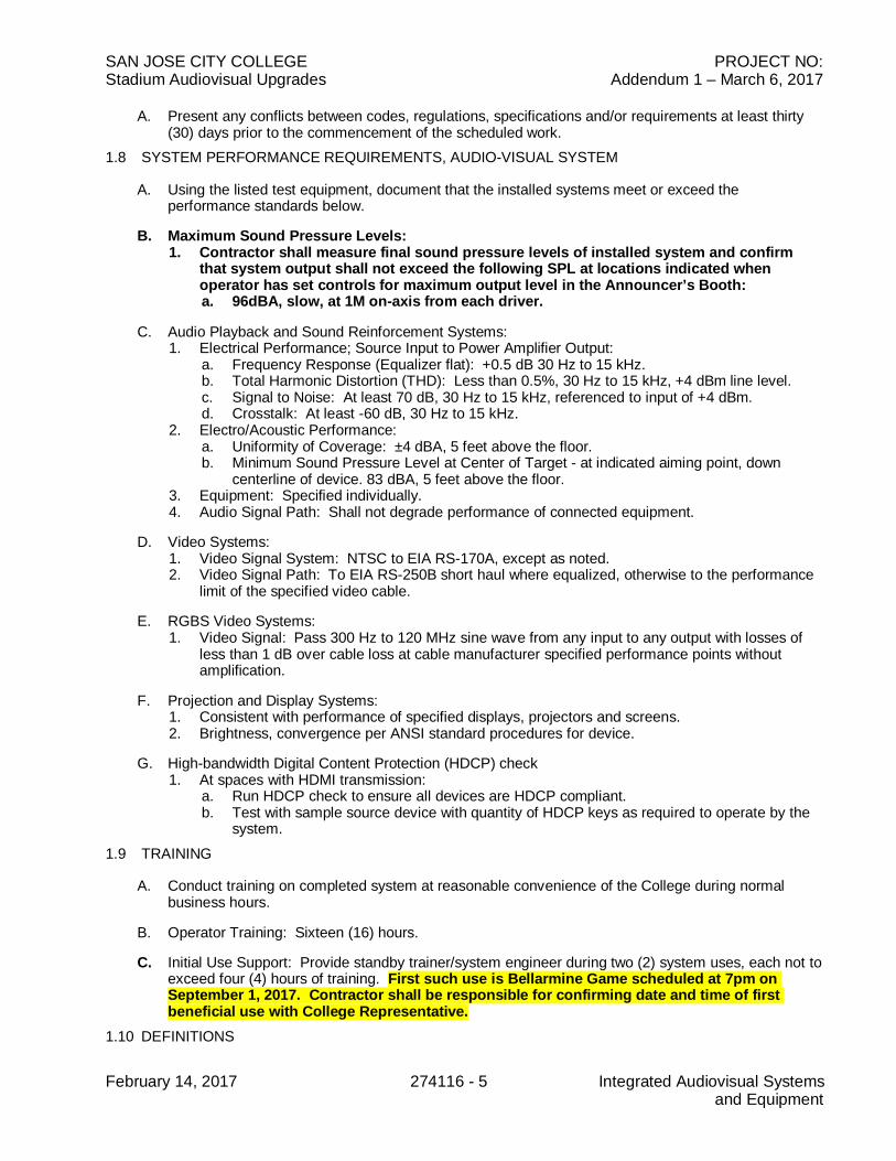
A. Present any conflicts between codes, regulations, specifications and/or requirements at least thirty(30) days prior to the commencement of the scheduled work.
1.8 SYSTEM PERFORMANCE REQUIREMENTS, AUDIO-VISUAL SYSTEM
A. Using the listed test equipment, document that the installed systems meet or exceed theperformance standards below.
B. Maximum Sound Pressure Levels:1. Contractor shall measure final sound pressure levels of installed system and confirm
that system output shall not exceed the following SPL at locations indicated whenoperator has set controls for maximum output level in the Announcer’s Booth:a. 96dBA, slow, at 1M on-axis from each driver.
C. Audio Playback and Sound Reinforcement Systems:1. Electrical Performance; Source Input to Power Amplifier Output:
a. Frequency Response (Equalizer flat): +0.5 dB 30 Hz to 15 kHz.b. Total Harmonic Distortion (THD): Less than 0.5%, 30 Hz to 15 kHz, +4 dBm line level.c. Signal to Noise: At least 70 dB, 30 Hz to 15 kHz, referenced to input of +4 dBm.d. Crosstalk: At least -60 dB, 30 Hz to 15 kHz.
2. Electro/Acoustic Performance:a. Uniformity of Coverage: ±4 dBA, 5 feet above the floor.b. Minimum Sound Pressure Level at Center of Target - at indicated aiming point, down
centerline of device. 83 dBA, 5 feet above the floor.3. Equipment: Specified individually.4. Audio Signal Path: Shall not degrade performance of connected equipment.
D. Video Systems:1. Video Signal System: NTSC to EIA RS-170A, except as noted.2. Video Signal Path: To EIA RS-250B short haul where equalized, otherwise to the performance
limit of the specified video cable.
E. RGBS Video Systems:1. Video Signal: Pass 300 Hz to 120 MHz sine wave from any input to any output with losses of
less than 1 dB over cable loss at cable manufacturer specified performance points withoutamplification.
F. Projection and Display Systems:1. Consistent with performance of specified displays, projectors and screens.2. Brightness, convergence per ANSI standard procedures for device.
G. High-bandwidth Digital Content Protection (HDCP) check1. At spaces with HDMI transmission:
a. Run HDCP check to ensure all devices are HDCP compliant.b. Test with sample source device with quantity of HDCP keys as required to operate by the
system.1.9 TRAINING
A. Conduct training on completed system at reasonable convenience of the College during normalbusiness hours.
B. Operator Training: Sixteen (16) hours.
C. Initial Use Support: Provide standby trainer/system engineer during two (2) system uses, each not toexceed four (4) hours of training. First such use is Bellarmine Game scheduled at 7pm onSeptember 1, 2017. Contractor shall be responsible for confirming date and time of firstbeneficial use with College Representative.
1.10 DEFINITIONS
SAN JOSE CITY COLLEGE PROJECT NO:Stadium Audiovisual Upgrades Addendum 1 – March 6, 2017
February 14, 2017 274116 - 6 Integrated Audiovisual Systemsand Equipment
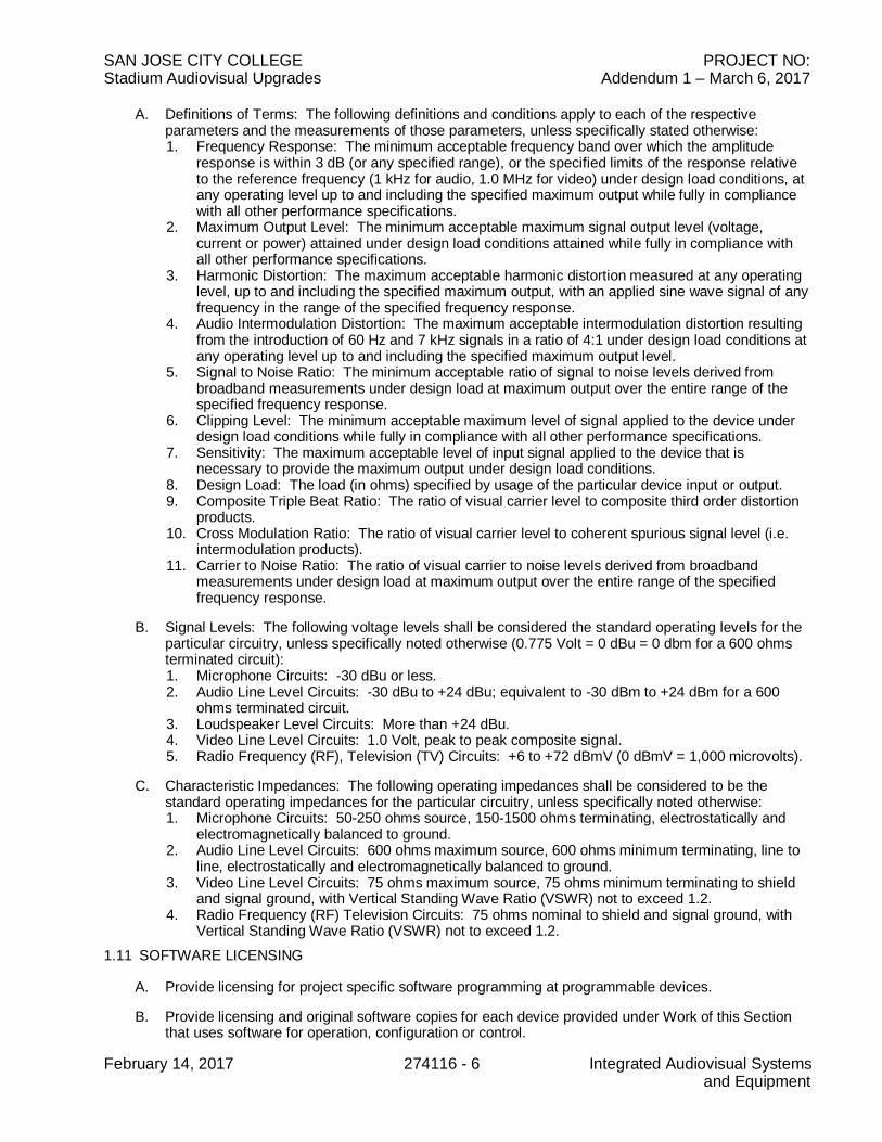
A. Definitions of Terms: The following definitions and conditions apply to each of the respectiveparameters and the measurements of those parameters, unless specifically stated otherwise:1. Frequency Response: The minimum acceptable frequency band over which the amplitude
response is within 3 dB (or any specified range), or the specified limits of the response relativeto the reference frequency (1 kHz for audio, 1.0 MHz for video) under design load conditions, atany operating level up to and including the specified maximum output while fully in compliancewith all other performance specifications.
2. Maximum Output Level: The minimum acceptable maximum signal output level (voltage,current or power) attained under design load conditions attained while fully in compliance withall other performance specifications.
3. Harmonic Distortion: The maximum acceptable harmonic distortion measured at any operatinglevel, up to and including the specified maximum output, with an applied sine wave signal of anyfrequency in the range of the specified frequency response.
4. Audio Intermodulation Distortion: The maximum acceptable intermodulation distortion resultingfrom the introduction of 60 Hz and 7 kHz signals in a ratio of 4:1 under design load conditions atany operating level up to and including the specified maximum output level.
5. Signal to Noise Ratio: The minimum acceptable ratio of signal to noise levels derived frombroadband measurements under design load at maximum output over the entire range of thespecified frequency response.
6. Clipping Level: The minimum acceptable maximum level of signal applied to the device underdesign load conditions while fully in compliance with all other performance specifications.
7. Sensitivity: The maximum acceptable level of input signal applied to the device that isnecessary to provide the maximum output under design load conditions.
8. Design Load: The load (in ohms) specified by usage of the particular device input or output.9. Composite Triple Beat Ratio: The ratio of visual carrier level to composite third order distortion
products.10. Cross Modulation Ratio: The ratio of visual carrier level to coherent spurious signal level (i.e.
intermodulation products).11. Carrier to Noise Ratio: The ratio of visual carrier to noise levels derived from broadband
measurements under design load at maximum output over the entire range of the specifiedfrequency response.
B. Signal Levels: The following voltage levels shall be considered the standard operating levels for theparticular circuitry, unless specifically noted otherwise (0.775 Volt = 0 dBu = 0 dbm for a 600 ohmsterminated circuit):1. Microphone Circuits: -30 dBu or less.2. Audio Line Level Circuits: -30 dBu to +24 dBu; equivalent to -30 dBm to +24 dBm for a 600
ohms terminated circuit.3. Loudspeaker Level Circuits: More than +24 dBu.4. Video Line Level Circuits: 1.0 Volt, peak to peak composite signal.5. Radio Frequency (RF), Television (TV) Circuits: +6 to +72 dBmV (0 dBmV = 1,000 microvolts).
C. Characteristic Impedances: The following operating impedances shall be considered to be thestandard operating impedances for the particular circuitry, unless specifically noted otherwise:1. Microphone Circuits: 50-250 ohms source, 150-1500 ohms terminating, electrostatically and
electromagnetically balanced to ground.2. Audio Line Level Circuits: 600 ohms maximum source, 600 ohms minimum terminating, line to
line, electrostatically and electromagnetically balanced to ground.3. Video Line Level Circuits: 75 ohms maximum source, 75 ohms minimum terminating to shield
and signal ground, with Vertical Standing Wave Ratio (VSWR) not to exceed 1.2.4. Radio Frequency (RF) Television Circuits: 75 ohms nominal to shield and signal ground, with
Vertical Standing Wave Ratio (VSWR) not to exceed 1.2.1.11 SOFTWARE LICENSING
A. Provide licensing for project specific software programming at programmable devices.
B. Provide licensing and original software copies for each device provided under Work of this Sectionthat uses software for operation, configuration or control.
SAN JOSE CITY COLLEGE PROJECT NO:Stadium Audiovisual Upgrades Addendum 1 – March 6, 2017
February 14, 2017 274116 - 7 Integrated Audiovisual Systemsand Equipment
1. Provide licensing for required workstation operating systems, and required third party software.2. For the Control System, provide a complete copy of the source code, including the device
interface driver code modules.
C. Upgrade each software package to the release in effect at the end of the Warranty Period.
PART 2 - PRODUCTS
2.1 DISTRIBUTED LOUDSPEAKER ASSEMBLIES AND RELATED
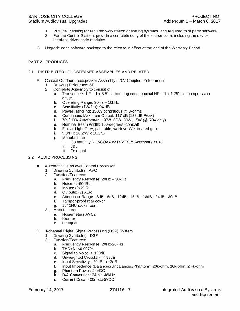
A. Coaxial Outdoor Loudspeaker Assembly - 70V Coupled, Yoke-mount1. Drawing Reference: SP2. Complete Assembly to consist of:
a. Transducers: LF – 1 x 6.5” carbon ring cone; coaxial HF -- 1 x 1.25” exit compressiondriver.
b. Operating Range: 90Hz – 16kHzc. Sensitivity: (1W/1m): 94 dBd. Power Handling: 150W continuous @ 8-ohmse. Continuous Maximum Output: 117 dB (123 dB Peak)f. 70v/100v Autoformer: 120W, 60W, 30W, 15W (@ 70V only)g. Nominal Beam Width: 100-degrees (conical)h. Finish: Light Grey, paintable, w/ NeverWet treated grillei. 9.0”H x 10,2”W x 10.2”Dj. Manufacturer
i. Community R.15COAX w/ R-VTY15 Accessory Yokeii. JBLiii. Or equal
2.2 AUDIO PROCESSING
A. Automatic Gain/Level Control Processor1. Drawing Symbol(s): AVC2. Function/Features:
a. Frequency Response: 20Hz – 30kHzb. Noise: < -90dBuc. Inputs: (2) XLRd. Outputs: (2) XLRe. Attenuator Range: -3dB, -6dB, -12dB, -15dB, -18dB, -24dB, -30dBf. Tamper-proof rear coverg. 19” 1RU rack mount
3. Manufacturer:a. Noisemeters AVC2b. Kramerc. Or equal.
B. 4-channel Digital Signal Processing (DSP) System1. Drawing Symbol(s): DSP2. Function/Features:
a. Frequency Response: 20Hz-20kHzb. THD+N: <0.007%c. Signal to Noise: > 120dBd. Unweighted Crosstalk: <-95dBe. Input Sensitivity: -20dB to +3dBf. Input Impedance (Balanced/Unbalanced/Phantom): 20k-ohm, 10k-ohm, 2,4k-ohmg. Phantom Power: 24VDCh. D/A Conversion: 24-bit, 48kHzi. Current Draw: 400ma@5VDC

SAN JOSE CITY COLLEGE PROJECT NO:Stadium Audiovisual Upgrades Addendum 1 – March 6, 2017
February 14, 2017 274116 - 8 Integrated Audiovisual Systemsand Equipment
j. Input Connectors: 3.5 Euro Blockk. Output Connectors: 3.5 Euro Blockl. LED Indicators: Power and Phantom Powerm. Controls: USB (Programming) and RS-232 (Operation)
3. Manufacturer - DSP Systema. Stewart Audio DSP4x4b. BiAmpc. Symetrixd. Or equal.
2.3 ASSISTIVE LISTENING SYSTEM (ALS):A. General
1. Provide Radio Frequency Type, Frequency Modulated2. 72 MHz Assistive Listening band.3. Quantity of Devices:
B. ALS Transmitter1. Drawing Symbol: ALS TX2. Features
a. Balanced bridging line input.b. Rack mounted.c. Connector for remote-mounted antenna.d. Selectable transmitting frequency.
3. Manufacturera. Listen Technologies LT-800-072 Stationary Transmitter with LA-326 Rack Mounting Kitb. Phonic Earc. Williams Sound Corpd. Or equal.
C. ALS Remote Transmitting Antenna1. Drawing Symbol: A2. Features
a. Antenna system with mounting hardware, matching specified ALS TX.3. Manufacturer
a. Listen Technologies LA-123b. Phonic Earc. Williams Sound Corpd. Or equal.
D. Receivers and Accessories1. Receiver
a. Battery powered, rechargeable.b. Volume control.c. Receptacle for earphone/accessory.d. Rechargeable battery.e. Tuneable to channel in use by the user.f. Quantity: As Scheduled on the plans
2. Earphonea. Ear hung, not inserted in the ear canal.b. Hearing-Aid Compatible - For hearing-aid compatible receivers:c. Wireless neck loop compatible with “T” coil hearing aids.d. Built-in antennae. Operates with provided receivers
3. Manufacturera. Listen Technologies LR-500-072-0-M-C, LA-164 earphones, and LA-166 neck loopsb. Phonic Earc. Williams Sound Corp
SAN JOSE CITY COLLEGE PROJECT NO:Stadium Audiovisual Upgrades Addendum 1 – March 6, 2017
February 14, 2017 274116 - 9 Integrated Audiovisual Systemsand Equipment
d. Or equal.E. Battery Charger/Storage/Carry Case
1. Featuresa. Store and charge up to 16 Receivers and related accessories.b. Cover, latches and carrying handles.c. Removable lid.
2. Quantity: To simultaneously recharge each received as scheduled on the plansa. Manufacturer
b. Listen Technologies LA-325c. Phonic Eard. Williams Sound Corpe. Or equal.
2.4 AUDIO SIGNAL SOURCE AND STORAGE:A. Rack-mounted Media Player
1. Drawing Reference: CD/Media/MP2. Features/Functions:
a. Audio Specificationsi. Audio channels: 2 channels / stereoii. Frequency response: 10 - 20,000 Hz, +/- 1.0dBiii. Dynamic range: > 85dB (10- 20,000 Hz A-weighted)iv. Signal to Noise ratio: > 90dB (1kHz, 0db, A-weighted)v. Channel separation: > 80dB (1kHz, 0dB, A-weighted)vi. Total Harmonic Distortion (THD): < 0.01% (1kHz, 0dB, A-weighted)
b. Analog Output (unbalanced)i. Type: RCA terminalii. Load impedance: > 10 kΩiii. Output level: 2 Vrms / at 10 kΩ load
c. Analog Output (balanced)i. Type: XLRii. Load impedance: > 10 kΩiii. Output level: +4 dBu
d. Input - AUX INi. Type: 1/8” (3.5mm) TRS terminalii. Input impedance: > 10 kΩiii. Maximum input level: 1 Vrms
e. Bluetooth Specificationsi. Output class: Class 2ii. Bluetooth version: 4.0iii. Supported profiles: A2DP, AVRCP, HFP, SPP, BAS, BLE, DIS, FMP, HRP, HRS,
HTP, HTS, IAS, LLSiv. Bluetooth range: 49 feet (15m)
f. Remote Controli. Type: IR Remoteii. Infrared Transmission Protocol: NEC formatiii. Transmit output level: >200mVp-p
g. Serial Remotei. D-sub 9-pin female RS-232Cii. Mode: Full duplexiii. Baud rate: 9600/38400 b/s (selectable in the menu)iv. Data: 8bitsv. Start bit: 1bitvi. Stop bit: 1bitvii. Parity: noneviii. Flow control: none
h. Audio File / SIGNALi. Sample rate: CD-DA, Audio file 44.1kHz
SAN JOSE CITY COLLEGE PROJECT NO:Stadium Audiovisual Upgrades Addendum 1 – March 6, 2017
February 14, 2017 274116 - 10 Integrated Audiovisual Systemsand Equipment
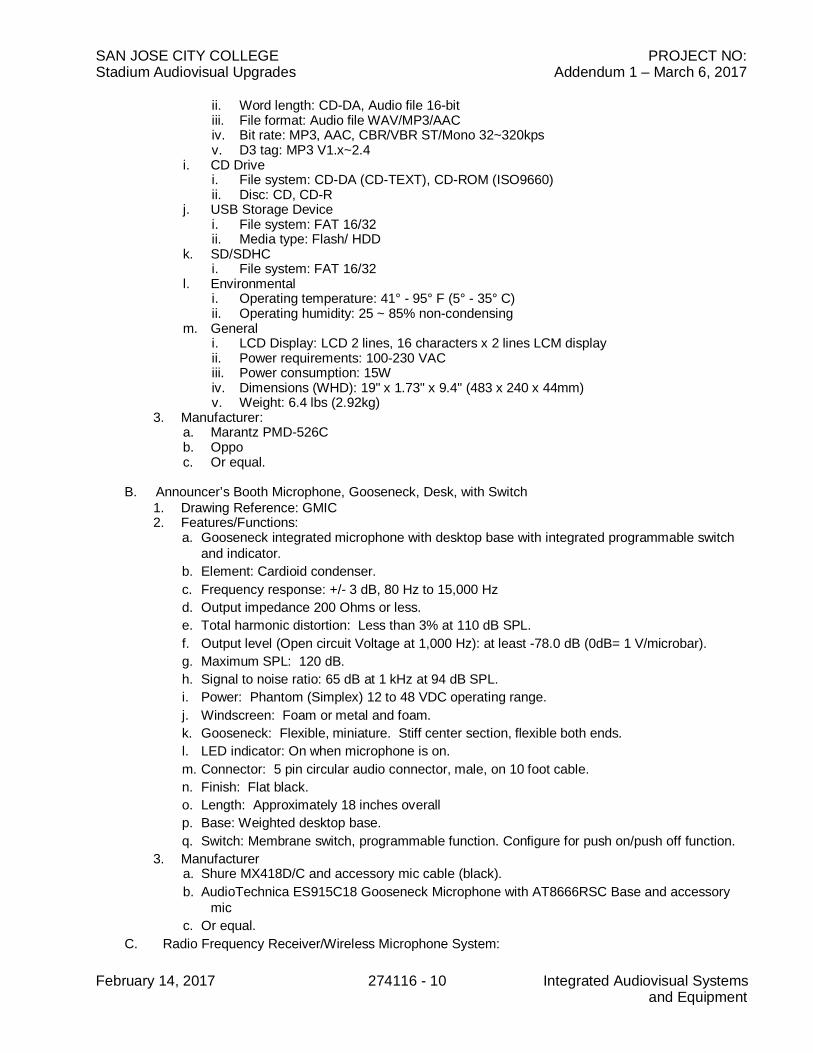
ii. Word length: CD-DA, Audio file 16-bitiii. File format: Audio file WAV/MP3/AACiv. Bit rate: MP3, AAC, CBR/VBR ST/Mono 32~320kpsv. D3 tag: MP3 V1.x~2.4
i. CD Drivei. File system: CD-DA (CD-TEXT), CD-ROM (ISO9660)ii. Disc: CD, CD-R
j. USB Storage Devicei. File system: FAT 16/32ii. Media type: Flash/ HDD
k. SD/SDHCi. File system: FAT 16/32
l. Environmentali. Operating temperature: 41° - 95° F (5° - 35° C)ii. Operating humidity: 25 ~ 85% non-condensing
m. Generali. LCD Display: LCD 2 lines, 16 characters x 2 lines LCM displayii. Power requirements: 100-230 VACiii. Power consumption: 15Wiv. Dimensions (WHD): 19" x 1.73" x 9.4" (483 x 240 x 44mm)v. Weight: 6.4 lbs (2.92kg)
3. Manufacturer:a. Marantz PMD-526Cb. Oppoc. Or equal.
B. Announcer’s Booth Microphone, Gooseneck, Desk, with Switch1. Drawing Reference: GMIC2. Features/Functions:
a. Gooseneck integrated microphone with desktop base with integrated programmable switchand indicator.
b. Element: Cardioid condenser.c. Frequency response: +/- 3 dB, 80 Hz to 15,000 Hzd. Output impedance 200 Ohms or less.e. Total harmonic distortion: Less than 3% at 110 dB SPL.f. Output level (Open circuit Voltage at 1,000 Hz): at least -78.0 dB (0dB= 1 V/microbar).g. Maximum SPL: 120 dB.h. Signal to noise ratio: 65 dB at 1 kHz at 94 dB SPL.i. Power: Phantom (Simplex) 12 to 48 VDC operating range.j. Windscreen: Foam or metal and foam.k. Gooseneck: Flexible, miniature. Stiff center section, flexible both ends.l. LED indicator: On when microphone is on.m. Connector: 5 pin circular audio connector, male, on 10 foot cable.n. Finish: Flat black.o. Length: Approximately 18 inches overallp. Base: Weighted desktop base.q. Switch: Membrane switch, programmable function. Configure for push on/push off function.
3. Manufacturera. Shure MX418D/C and accessory mic cable (black).b. AudioTechnica ES915C18 Gooseneck Microphone with AT8666RSC Base and accessory
micc. Or equal.
C. Radio Frequency Receiver/Wireless Microphone System:

SAN JOSE CITY COLLEGE PROJECT NO:Stadium Audiovisual Upgrades Addendum 1 – March 6, 2017
February 14, 2017 274116 - 11 Integrated Audiovisual Systemsand Equipment
1. Drawing Reference(s):a. WMRXb. WMIC LAV - Wireless Mic, Lavalierc. Wireless microphone symbol.
2. Provide quantity of complete systems to match quantity of WMIC LAV microphone symbolsshown.a. Coordinate operating frequency with other UHF local sources, including but not limited to
current television operating frequencies and DTV frequency allocations and/or local publicsafety operating frequencies to eliminate any interference from outside RF sources.
b. Provide Receiver unit configured for diversity reception.c. Allows the expansion of wireless microphone systems by splitting one pair of antennas to
multiple receivers. It also amplifies RF signals to compensate for insertion loss that resultsfrom splitting signal power to multiple outputs. A single system can support up to fourwireless receivers.
3. Function/Features/Performance:a. WMRX/WMIC LAV
i. Operating Range Under Typical Conditions: 100m (300 ft.) Note: actual rangedepends on RF signal absorption, reflection, and interference.
ii. Audio Frequency Response (+/– 2 dB): Minimum: 45 Hz; Maximum: 15 kHziii. Total Harmonic Distortion (ref. +/– 38 kHz deviation, 1 kHz tone): 0.5%, typicaliv. Dynamic Range: >100 dB A-weightedv. Operating Temperature Range: –18°C (0°F) to +57°C (+135°F)
Note: battery characteristics may limit this rangevi. Transmitter Audio Polarity: Positive pressure on microphone diaphragm (or positive
voltage applied to tip of WA302 phone plug) produces positive voltage on pin 2 (withrespect to pin 3 of low impedance output) and the tip of the high impedance 1/4-inchoutput.
4. Manufacturer, WMIC LAV System:a. Shure QLXD24/SM58 Digital Wireless Handheld System w/ SM58 Cartridge, Shure QLXD14
Bodypack System, and Shure WCE6T Omnidirectional Condenser Rigid EarsetMicrophone, tan.
b. Or equal.
2.5 MEDIA INPUTS AND RELATED
A. Announcer’s Booth Microphone Patch Panel, Wall-mount1. Drawing Reference: MP12. Features/Functions:
a. 2x XLR Neutrik D-series Female (NC3FD-L-1) connectors w/ rear solder points, panel-mount.
b. 2-gang3. Manufacturer:
a. Seismic Audiob. ProCoc. Or equal
2.6 SOUND CABLES AND RELATED
A. General1. Provide cable with electrical conductors of soft drawn annealed copper, bare or tinned, solid or
concentric stranded as applies, conductivity not less than 98 percent of pure copper.2. Comply with applicable Code for insulation, jacket, marking and listing for applicable use.
a. Refer to California Electrical Code, Table 725-61. Cable Uses and Permitted Substitutions.
SAN JOSE CITY COLLEGE PROJECT NO:Stadium Audiovisual Upgrades Addendum 1 – March 6, 2017
February 14, 2017 274116 - 12 Integrated Audiovisual Systemsand Equipment
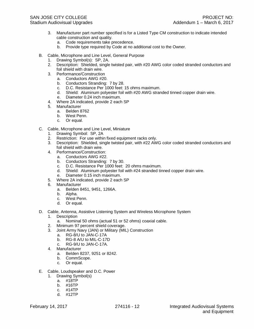
3. Manufacturer part number specified is for a Listed Type CM construction to indicate intendedcable construction and quality.a. Code requirements take precedence.b. Provide type required by Code at no additional cost to the Owner.
B. Cable, Microphone and Line Level, General Purpose1. Drawing Symbol(s): SP, 2A.2. Description: Shielded, single twisted pair, with #20 AWG color coded stranded conductors and
foil shield with drain wire.3. Performance/Construction
a. Conductors AWG #20.b. Conductors Stranding: 7 by 28.c. D.C. Resistance Per 1000 feet: 15 ohms maximum.d. Shield: Aluminum polyester foil with #20 AWG stranded tinned copper drain wire.e. Diameter 0.24 inch maximum.
4. Where 2A indicated, provide 2 each SP5. Manufacturer
a. Belden 8762b. West Penn.c. Or equal.
C. Cable, Microphone and Line Level, Miniature1. Drawing Symbol: SP, 2A2. Restriction: For use within fixed equipment racks only.3. Description: Shielded, single twisted pair, with #22 AWG color coded stranded conductors and
foil shield with drain wire.4. Performance/Construction:
a. Conductors AWG #22.b. Conductors Stranding: 7 by 30.c. D.C. Resistance Per 1000 feet: 20 ohms maximum.d. Shield: Aluminum polyester foil with #24 stranded tinned copper drain wire.e. Diameter 0.15 inch maximum.
5. Where 2A indicated, provide 2 each SP6. Manufacturer
a. Belden 8451, 9451, 1266A.b. Alpha.c. West Penn.d. Or equal.
D. Cable, Antenna, Assistive Listening System and Wireless Microphone System1. Description
a. Nominal 50 ohms (actual 51 or 52 ohms) coaxial cable.2. Minimum 97 percent shield coverage.3. Joint Army Navy (JAN) or Military (MIL) Construction
a. RG-8/U to JAN-C-17Ab. RG-8 A/U to MIL-C-17Dc. RG-9/U to JAN-C-17A.
4. Manufacturera. Belden 8237, 9251 or 8242.b. CommScope.c. Or equal.
E. Cable, Loudspeaker and D.C. Power1. Drawing Symbol(s)
a. #18TPb. #16TPc. #14TPd. #12TP
SAN JOSE CITY COLLEGE PROJECT NO:Stadium Audiovisual Upgrades Addendum 1 – March 6, 2017
February 14, 2017 274116 - 13 Integrated Audiovisual Systemsand Equipment
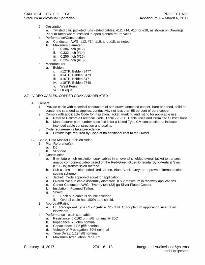
2. Descriptiona. Twisted pair, jacketed, unshielded cables, #12, #14, #16, or #18, as shown on Drawings.
3. Plenum rated where installed in open plenum return voids.4. Performance/Construction
a. Conductor, AWG: #12, #14, #16, and #18, as noted.b. Maximum diameter
i. 0.384 inch (#12)ii. 0.332 inch (#14)iii. 0.256 inch (#16)iv. 0.224 inch (#18).
5. Manufacturera. Belden.
i. #12TP, Belden 8477ii. #14TP, Belden 8473iii. #16TP, Belden 8471iv. #18TP, Belden 9740v. West Penn.vi. Or equal.
2.7 VIDEO CABLES, COPPER COAX AND RELATED
A. General1. Provide cable with electrical conductors of soft drawn annealed copper, bare or tinned, solid or
concentric stranded as applies, conductivity not less than 98 percent of pure copper.2. Comply with applicable Code for insulation, jacket, marking and listing for applicable use.
a. Refer to California Electrical Code, Table 725-61. Cable Uses and Permitted Substitutions.b. Manufacturer part number specified is for a Listed Type CM construction to indicate
intended cable construction and quality.3. Code requirements take precedence.
a. Provide type required by Code at no additional cost to the Owner.
B. Cable, Data Monitor Precision Video1. Plan Reference(s):
a. D5b. 5DVideo
2. Constructiona. 5 miniature high resolution coax cables in an overall shielded overall jacket to transmit
analog component video based on the Red-Green-Blue-Horizontal Sync-Vertical Sync(RGBHV) transmission method.
b. Sub cables are color coded Red, Green, Blue, Black, Grey; or approved alternate colorcoding scheme.
c. Jacket: Code approved equal for application.d. Overall five sub cable assembly diameter: 0.56" maximum in raceway applications.e. Center Conductor AWG: Twenty two (22) ga Silver Plated Copper.f. Insulation: Foamed Teflon.g. Shield:
i. Each sub-cable is double shieldedii. Overall cable has 100% tape shield.
3. Approval/Rating:a. UL: Recognized Type CL2P (Article 725 of NEC) for plenum application, riser rated
elsewhere.4. Performance - each sub-cable:
a. Resistance: 0.0162 ohms/ft nominal @ 20Cb. Impedance: 75 ohm nominalc. Capacitance: 17.5 pf/ft nominald. Velocity of Propagation: 80% nominale. Time Delay: 1.19ns/ft nominalf. Maximum Attenuation Per 100':

SAN JOSE CITY COLLEGE PROJECT NO:Stadium Audiovisual Upgrades Addendum 1 – March 6, 2017
February 14, 2017 274116 - 14 Integrated Audiovisual Systemsand Equipment
i. 10 MHz: 0.8 dB/100 ft.ii. 50 MHz: 2.5 dB/100 ft.iii. 100 MHz: 3.5 dB/100 ft.iv. 200 MHz: 4.6 dB/100 ft.v. 300 MHz: 5.0 dB/100 ft.vi. 400 MHz: 7.2 dB/100 ft.vii. 1000 MHz: 14.6 dB/100 ft.
5. Manufacturers:a. Altinex CB5100PL in plenum spaces, riser rated elsewhere.b. Extronc. Beldend. Gepco.e. or equal.
C. HDMI/DVI Cabling1. Drawing Reference: DVI/HDMI2. Features/Functions
a. The plans indicate the required distances for HDMI format transmission. Contractor toprovide a transmission system appropriate to the indicated lengths. Contractor engineeredsolutions may consist of:i. Passive HDMI cabling, where the indicated length is within the service distance of
such systems.ii. Copper HDMI cabling and active HMDI repeatersiii. Fiber Optic Cabling and HDMI transceivers.
b. Contractor to select and provide the method of transmission appropriate to the length andoperating parameters of the selected transmission system as defined by the manufacturersof the cabling systems, the repeaters and/or transceivers and the HDMI transmissionstandard as defined at www.hdmi.com.
3. Manufacturers, copper cabling and extenders:a. Extronb. Broadatac. Altinexd. Liberty Cablee. or equal.
2.8 CONTROL CABLING
A. General1. Provide cable with electrical conductors of soft drawn annealed copper, bare or tinned, solid or
concentric stranded as applies, conductivity not less than 98 percent of pure copper.2. Comply with applicable Code for insulation, jacket, marking and listing for applicable use.
a. Refer to California Electrical Code, Table 725-61. Cable Uses and Permitted Substitutions.b. Manufacturer part number specified is for a Listed Type CM construction to indicate
intended cable construction and quality.3. Code requirements take precedence.
a. Provide type required by Code at no additional cost to the Owner.
B. USB Cabling1. Drawing Reference: USB2. Features/Functions:
a. Conforms with minimum USB 2.0 standardb. Provides USB input in a single gang wall platec. Extends USB signal up to at least 200' or distance as required by project requirements.
3. Manufacturers:a. Extronb. Trulinkc. or equal.
C. High Speed, TIA/TIA Category Cabling

SAN JOSE CITY COLLEGE PROJECT NO:Stadium Audiovisual Upgrades Addendum 1 – March 6, 2017
February 14, 2017 274116 - 15 Integrated Audiovisual Systemsand Equipment
1. Drawing Reference:** UTP6-4, where ** denotes cable count2. Construction:
a. Provide horizontal copper cable in accordance with:i. EIA ANSI/TIA/EIA-568-B.2ii. UL 444,iii. NEMA WC 66 (Performance Standard for Category 6 and Category 7 100 Ohm
Shielded and Unshielded Twisted Pair)iv. ICEA S-90-661
b. UTP (unshielded twisted pair),c. 100 ohm impedanced. Four each individually twisted pair, 22 or 24 AWG conductors,
i. Color code(1) Pair 1 White/Blue Blue(2) Pair 2 White/Orange Orange(3) Pair 3 White/Green Green(4) Pair 4 White/Brown Brown
e. No shield in the sheath.f. Jacket
i. Thermoplastic jacketii. Color: Blue unless otherwise indicated.iii. Cable imprinted with manufacturers name or identifier, flammability rating, gauge of
conductor, transmission performance rating (category designation) at regular intervalsnot to exceed 2 feet.
iv. The word "FEET" or the abbreviation "FT" shall appear after each length marking.v. Provide communications general purpose (CM or CMG), communications plenum
(CMP) or communications riser (CMR) rated cabling in accordance with NFPA 70.vi. Type CMP and CMR may be substituted for type CM or CMG and type CMP may be
substituted for type CMR in accordance with NFPA 70.3. Certification
a. Warrantied by the manufacturer to provide Category 6 performance when installed inaccordance with applicable EIA/TIA standards and when terminated with the jacks suppliedby the Contractor for this Project.
4. Performancea. Assembly electrically meets or exceeds EIA ANSI/TIA/EIA-568-B.2 Category 6
performance standards5. Manufacturers:
a. Berk-Tek LANmark-1000b. Belden/CDTc. Berk-Tekd. Commscope/Systimaxe. Commscope/Uniprisef. General Cableg. Mohawk/CDTh. Superior/Essexi. or equal
D. High Speed, Category 6 Cabling, Plenum Rated1. Drawing Reference:** UTP6-4P, where ** denotes cable count2. Construction:
a. As for non-plenum, with fire retardant overall jacket construction.b. UL listed, NEC compliant for plenum installation.c. CSA Certified type PCC FT4 FT6.
3. Manufacturersa. As for non-plenum Cat-6, plenum construction.
2.9 MISCELLANEOUS PRODUCTS
A. Audio and Control Connectors and Related:
SAN JOSE CITY COLLEGE PROJECT NO:Stadium Audiovisual Upgrades Addendum 1 – March 6, 2017
February 14, 2017 274116 - 16 Integrated Audiovisual Systemsand Equipment
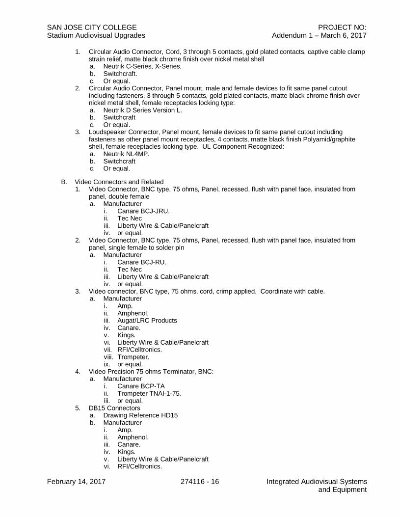
1. Circular Audio Connector, Cord, 3 through 5 contacts, gold plated contacts, captive cable clampstrain relief, matte black chrome finish over nickel metal shella. Neutrik C-Series, X-Series.b. Switchcraft.c. Or equal.
2. Circular Audio Connector, Panel mount, male and female devices to fit same panel cutoutincluding fasteners, 3 through 5 contacts, gold plated contacts, matte black chrome finish overnickel metal shell, female receptacles locking type:a. Neutrik D Series Version L.b. Switchcraftc. Or equal.
3. Loudspeaker Connector, Panel mount, female devices to fit same panel cutout includingfasteners as other panel mount receptacles, 4 contacts, matte black finish Polyamid/graphiteshell, female receptacles locking type. UL Component Recognized:a. Neutrik NL4MP.b. Switchcraftc. Or equal.
B. Video Connectors and Related1. Video Connector, BNC type, 75 ohms, Panel, recessed, flush with panel face, insulated from
panel, double femalea. Manufacturer
i. Canare BCJ-JRU.ii. Tec Neciii. Liberty Wire & Cable/Panelcraftiv. or equal.
2. Video Connector, BNC type, 75 ohms, Panel, recessed, flush with panel face, insulated frompanel, single female to solder pina. Manufacturer
i. Canare BCJ-RU.ii. Tec Neciii. Liberty Wire & Cable/Panelcraftiv. or equal.
3. Video connector, BNC type, 75 ohms, cord, crimp applied. Coordinate with cable.a. Manufacturer
i. Amp.ii. Amphenol.iii. Augat/LRC Productsiv. Canare.v. Kings.vi. Liberty Wire & Cable/Panelcraftvii. RFI/Celltronics.viii. Trompeter.ix. or equal.
4. Video Precision 75 ohms Terminator, BNC:a. Manufacturer
i. Canare BCP-TAii. Trompeter TNAI-1-75.iii. or equal.
5. DB15 Connectorsa. Drawing Reference HD15b. Manufacturer
i. Amp.ii. Amphenol.iii. Canare.iv. Kings.v. Liberty Wire & Cable/Panelcraftvi. RFI/Celltronics.
SAN JOSE CITY COLLEGE PROJECT NO:Stadium Audiovisual Upgrades Addendum 1 – March 6, 2017
February 14, 2017 274116 - 17 Integrated Audiovisual Systemsand Equipment
vii. or equal.
C. Custom Facility Panels, Rackmount Auxiliary Panels, Rack Lighting1. Drawing Reference(s):
a. MP* - Media Panels, where * is a number indicating the panel type.b. FP* - Facility Panels, where * is a number indicating the panel type.c. Aux Panel
2. Provide connector types and plate finish as shown. If none shown, provide:a. Rack mount panels:
i. 16 gauge minimum, cold rolled steel or 1/8" minimum aluminum, finish to match rackfinish.
ii. At contractor's option, fabricate using rack mount panels with Decora/Decoratoropenings and steel plates with specified connectors. Match insert color to panel colorprovided. Refer to Rack Panel with Decora Openings below.
b. Wall Panels: 16 gauge minimum cold rolled steel, finish to match surrounding electricaland other low voltage panels.
3. Manufacturers, Rack Mount Panelsa. BGW Systems Inc.b. Conquestc. Middle Atlantic Products Universal Connector Paneld. Middle Atlantic Products Universal Connector Panel, Modular Custom Connector Panel
Systemse. ProCo Sound, Inc.f. Ultimate Plates and Panelsg. or equal.
4. Manufacturers, Wall Panelsa. PanelCrafters Division of Liberty Wire & Cable, Classic Seriesb. FSRc. RCI Systemsd. Middle Atlantice. Ultimate Plates and Panelsf. Whirlwindg. Or equal.
5. Manufacturers, Decora/Decorator connector inserts:a. Connector Plates by Radio Design Labs. Provide specified connectors rear mounted in D-
Blank insert for connector combinations not available from RDL.b. Grey by Pathway Connectivity Solutions. Provide specified connectors rear mounted in
5100 insert for connector combinations not available from Pathway Connectivity Solutions.c. or equal.
6. Manufacturers, Rack Mount Decora Panel Openingsa. Lowell Manufacturing LD8-RMP with Lowell DBB-4 blank Decora plates at openings not
fitted with equipment.b. Middle Atlantic DECP Seriesc. or equal.
7. Manufacturers, Rack Lightinga. Middle Atlantic PDLT-815RV-RN.b. or equal.
2.10 POWER DISTRIBUTION EQUIPMENTA. Comply with applicable Codes. Provide UL Listed devices suitable for commercial use. Provide all
junction boxes, raceway, fittings, wire, supports and fastenings as required for complete installation.Contractor to coordinate plug end of selected strip with rack power receptacles installed under thework of Division 16. Unless otherwise noted, provide receptacles of NEMA 5-15R configuration.
B. Power Sequencer System1. Drawing References: PSEQ
a. Power Sequencerb. Fire Alarm Interface – provide where required to shunt system operation on receipt of
closure from Fire Alarm system.
SAN JOSE CITY COLLEGE PROJECT NO:Stadium Audiovisual Upgrades Addendum 1 – March 6, 2017
February 14, 2017 274116 - 18 Integrated Audiovisual Systemsand Equipment
c. Sold State Relay (SSR) SSR1 through SSR72. Features
a. Power sequencing system.b. Solid state switching, zero crossing.c. Sequencing on power up and power down.d. Front panel button and external closure activation.e. Alarm terminal to sequence the system down when tripped.f. UL Listed.
3. Manufacturera. FSR Inc. Power Products Group SPC-20 Power Sequencer and SPC-20X Solid State
Relayb. Furmanc. Or equal.
C. Power Supplies and Related:1. Drawing Reference: PS24.2. Relay and Lamp Power Supply:3. 24 VDC, regulated within 5%. Ripple not greater than 1.5%. Output current rating at least
150% of maximum possible load. Circuit breaker or intrinsic over current protection. ULRecognized or UL Listed.
D. Full Height Receptacle Strip, One (1) Circuit, 15A1. Features/Construction:
a. Not less than 60" Longb. Not less than eleven (11) 15A receptaclesc. Integral circuit breakerd. NEMA 5-15P plug on 6' cord.e. UL Listed Assemblyf. Provide mounting hardware as necessary to attach to rack interior.
2. Manufacturers.a. Wiremold Series 7011ULBC.b. Lowell ACS 1524c. Geist NSVB200-101S15d. Hubbell PR206e. Levitonf. Middle Atlanticg. Chatsworth 12848-701h. or equal.
E. Full Height Receptacle Strip, One (1) Circuit, 20A1. Features/Construction:
a. Not less than 70" Longb. Not less than eleven (11) 15A receptaclesc. Integral circuit breakerd. NEMA 5-20P plug on 6' cord.e. UL Listed Assemblyf. Provide mounting hardware as necessary to attach to rack interior.
2. Manufacturers. Contractor to coordinate selected strip with rack power receptacles installedunder the work of Division 26.a. Geist NSVB200-102S20b. Hubbell PR20820DRTLc. Leviton P104x seriesd. Lowell ACS-2024e. Midde Atlantic PD-1020C-NSf. Wiremold Series 7011ULBC20.g. Chatsworth 12848-705h. or equal.
F. Rackmount Power Panel, Horizontal Mount, User Aux device use:1. Drawing Reference: POWER.2. Functions/Features:
a. Front face of panel shall provide two electrical power outlets and a switch. An indicator
SAN JOSE CITY COLLEGE PROJECT NO:Stadium Audiovisual Upgrades Addendum 1 – March 6, 2017
February 14, 2017 274116 - 19 Integrated Audiovisual Systemsand Equipment
lamp shall show the presence of AC power when on. The front face of panel shall havea black finish. The rear face shall provide a minimum of at least four receptacles. Thepanel shall be racked mounted in a maximum of two rack units. The panel shall beCode approved and UL rated for this application.
3. Manufacturers:a. Hubbell MCCPSS19TSb. Leviton 4515c. Geist SP124-1020
2.11 POWER PANEL:1. Drawing Reference: POWER.2. Functions/Features:
a. Front face of panel shall provide two electrical power outlets and a switch. An indicatorlamp shall show the presence of AC power when on. The front face of panel shall have ablack finish. The rear face shall provide a minimum of at least four receptacles. The panelshall be racked mounted in a maximum of two rack units. The panel shall be Codeapproved and UL rated for this application.
3. Manufacturers:a. Hubbell MCCPSS19TSb. Geist SP124-1020c. Or equal.
PART 3 - EXECUTION
3.1 GENERAL
A. Perform the Work of this Section in accordance with acknowledged industry and professionalstandards and practices, and the procedures specified herein.
B. Furnish and install (herein, "provide") all materials, devices, components, and equipment required forcomplete, operational systems.
C. Refer to Section 27 15 00 for additional execution requirements that apply to the work of this Section.3.2 PRECONSTRUCTION PROGRAMMING MEETING
A. Not less than 60 days prior to the scheduled completion of the project, Contractor to initiate a requestof the Owner's Representative to schedule an Audiovisual Systems programming meeting.1. The Owner's Representative will schedule the meeting at the reasonable mutual convenience of
the Contractor and the Owner's technical systems representatives.2. The purpose of the meeting is for the Owner's Representative to indicate to the contractor how
the programmable interfaces of the Audiovisual systems are to be implemented, including:a. Integration of VoIP conference dialing into AV controls.b. Button assignments and labels for physical button panelsc. Touchscreen menu hierarchy, scene arrangement, button and background colors, text
size, logosd. When multiple panels control the same systems, which screens appear on which
touchpanels.e. Whether authorization codes or passwords will be required to access special
functions/menus.3. Contractor to document the information received from the Owner's Representatives at this
meeting.4. Contractor to submit the documentation of the requirements meeting, along with their proposed
response to the Owner's programming requirements in the form of screen shots and systemmenu flow diagrams as required under Section 27 41 00 – Common Work Results forAudiovisual Systems, 1.4 D Submittals.
3.3 WIRING CLASSIFICATION AND RELATED
SAN JOSE CITY COLLEGE PROJECT NO:Stadium Audiovisual Upgrades Addendum 1 – March 6, 2017
February 14, 2017 274116 - 20 Integrated Audiovisual Systemsand Equipment
A. Audio Signal Wiring Classification:1. Type A-l: Microphone level wiring less than -30 dBμ, 20 Hz to 20 kHz.2. Type A-2: Line level wiring -30 dBμ to +24 dBμ, 20 Hz to 20 kHz.3. Type A-3: Loudspeaker level or circuit wiring greater than +24 dBμ, from 20 Hz to 20 kHz.
B. Video and Related Signal Wiring Classification:1. Type V-1: Baseband and composite video wiring 1 volt peak-to-peak into 75 ohms, 0 to 10.0
MHz.2. Type V-2: Synchronization and switching pulse wiring 4 volts peak-to-peak into 75 ohms, 15.62
to 15.75 kHz.3. Type V-3: Color subcarrier wiring 0 to 4 volts peak-to-peak into 75 ohms, 3.57 to 4.43 MHz.4. Type V-4: TV system wiring 0.1 to 1000 uV peak-to-peak into 50 or 75 ohms, 47 to 890 MHz.
C. Control Signal Wiring Classifications:1. Type C-1: DC control wiring 0 to 50 volts.2. Type C-2: Synchronous control or data wiring 0 to 40 volts, peak-to-peak.3. Type C-3: AC control wiring 0 to 48 volts, 60 Hz.
D. Additional Wiring Classifications:1. Type M-1: DC power wiring 0 to 48 volts.2. Type M-2: AC power wiring greater than 50 volts, 60 Hz.
E. Wiring Combinations:1. Except as indicated herein, conduit, wireways and cable bundles shall contain only wiring of a
single classification. The following combinations are acceptable in conduit, or cable harnesses.Additional acceptable combinations may be indicated on the Contract Drawings.a. Types A-1, C-1, and M-1.b. Types A-2, C-l, C-2, and M-l, runs less than twenty (20) feet.c. Types A-2, C-1, and M-1.d. Types A-3, C-1, C-2, and M-1.e. Types A-2, V-1, and V-3.f. Types V-1, V-2, V-3, and C-1.g. Types M-2 and C-3.
3.4 WIRE AND CABLE INSTALLATION
A. Provide permanent identification of run destination at all raceway terminations.
B. All wire and cable shall be continuous and splice-free for the entire length of run between designatedconnections or terminations.
C. All shielded cables shall be insulated. Do not permit shields to contact conduit, raceway, boxes,panels or equipment enclosures.
D. Within buildings, make splices only in designated terminal cabinets and/or on designated equipmentbackboards. Outside buildings, make splices only in designated manholes and/or handholes.Protect splices outside of buildings with splicing kits equivalent to Scotchcast Re-enterable. Makesplices only with connectors or terminal devices specified herein. Document all splices on RecordDrawings.
E. Verify that all raceway has been de-burred and properly joined, coupled, and terminated prior toinstallation of cables. Verify that all raceway is clear of foreign matter and substances prior toinstallation of wire or cable.
F. Inspect all conduit bends to verify proper radius. Comply with Code for minimum permissible radiusand maximum permissible deformation.
G. Apply a chemically inert lubricant to all wire and cable prior to pulling in conduit. Do not subject wireand cable to tension greater than that recommended by the manufacturer. Use multi-spool rollerswhere cable is pulled in place around bends. Do not pull reverse bends.

SAN JOSE CITY COLLEGE PROJECT NO:Stadium Audiovisual Upgrades Addendum 1 – March 6, 2017
February 14, 2017 274116 - 21 Integrated Audiovisual Systemsand Equipment
H. Provide a box loop for all wire and cable routed through junction boxes or distribution panels.Provide tool formed thermal expansion loops at cable at manholes, handholes and at both sides ofall fixed mounted equipment. Cable loops and bends shall not be bent at a radius greater than thatrecommended by the manufacturer.
I. Secure all wire and cable run vertically for continuous distances greater than thirty (30) feet. Securerobust non-coaxial cables with screw-flange nylon cable ties or similar devices appropriate to weightof cable. For all other cables, provide symmetrical conforming nonmetallic bushings or woven cablegrips appropriate to weight of cable.
3.5 SIGNAL POLARITY CONVENTION
A. Maintain consistent absolute signal polarity at all connectors, patch points and connection pointsaccessible in the system. Comply with AES26-2001.Where applicable, a positive polarity electricalsignal shall yield positive acoustic pressure from the loudspeakers.
B. Audio signal connector convention: Comply with AES 14-1992 (r1998)Signal Connector WireSignal Phase Pin 2 Red or WhiteSignal Anti-Phase Pin 3 BlackSignal Ground Pin 1 Drain Wire
C. Video and RF/TV Connector Convention:Signal Connector WireSignal Phase Center Pin Center conductorSignal Anti-Phase Shell ShieldSignal Ground Shell Shield
3.6 WIRING PRACTICE
A. Land all non-coaxial field wiring entering each equipment rack at specified terminal devices prior toconnection to any equipment or devices within racks. At Contractor's option, such terminals may belocated in the equipment racks or in the terminal cabinets provided. Coordinate such selection withProject construction sequence and test procedures specified herein.
B. Identify all wire and cable clearly with permanent labels wrapped about the full circumference withinone (1) inch of each connection. Indicate the number designated on the associated field or shopdrawing or run sheet, as applies. Assign wire or cable designations consistently throughout a givensystem. Each wire or cable shall carry the same labeled designation over its entire run, regardless ofintermediate terminations. Conform with the requirements of Section 27 41 00.
C. Apply all crimp connectors only with manufacturer's recommended ratchet type tooling and correctcrimp dies for connector and wire size. Plier type crimp tooling shall not be acceptable.
D. Coordinate insulation displacement (quick connect) terminal devices with wire size and type. Complywith manufacturer's recommendations. Make connections with automatic impact type tooling set torecommended force.
E. Make all connections to screw-type barrier blocks with insulated crimp-type spade lugs. Lugs are notrequired at captive compression terminal type blocks. Provide permanent designation stripsdesigned for use with the terminal blocks provided. Make neat, intelligible markings with indeliblemarkers equivalent to "Sharpie".
F. Tin terminated shield drain wires and insulate with heat shrinkable tubing.
G. Use only rosin core 60/40 tin/lead solder for all solder connections.
H. Dress, lace or harness all wire and cable to prevent mechanical stress on electrical connections. Nowire or cable shall be supported by a connection point. Provide service loops where harnesses ofdifferent classes cross, or where hinged panels are to be interconnected.
SAN JOSE CITY COLLEGE PROJECT NO:Stadium Audiovisual Upgrades Addendum 1 – March 6, 2017
February 14, 2017 274116 - 22 Integrated Audiovisual Systemsand Equipment
I. Termination and build-out resistors and related circuit correction components shall be visible. Do notinstall in connector shells or internally modify equipment. Show locations on Record Drawings.
J. Correct any and all of the following unacceptable wiring conditions:1. Deformed, brittle or cracked insulation.2. Insulation shrunken or stripped further than 1/8" away from the actual point of connection within
a connector, or on a punch block.3. Cold solder joints.4. Flux joints.5. Solder splatter.6. Un-grommeted, un-bushed, or uninsulated wire or cable entries.7. Deformation or improper radius of wire or cable.
3.7 SIGNAL GROUNDING PROCEDURES
A. Comply with National Electrical Code.
B. Unless otherwise noted maintain a unipoint ground scheme.
C. Signal and electrical system grounds shall be isolated except at the Project ground field connection.
D. Equipment enclosures shall not be permitted to touch each other unless bolted together andelectrically bonded.
E. Ground and bond equipment racks and similar equipment enclosures containing powered equipmentexclusively via the ground conductors provided under Division 27.
F. At each rack, provide a ground bus within the rack. At each rack, provide a lug bonded to the rackframe with a #12 TW stranded wire to the rack Ground bus.
G. At each ensemble of racks, provide a single labeled Ground tubular-clamp bus bar terminal strip toland the individual rack Isolated Ground bus ground conductors. Connect the main Isolated Groundconductor from the Technical Power panelboard at this point.
H. Equipment signal ground shall be to the Ground System via the green wire of the equipment powercord. Where equipment uses two (2) wire power cord, provide #12 green bond wire to rack groundbus bar. At equipment, provide crimp lug and suitable hardware for bonding.
I. Shielded cables of this section shall be grounded exclusively to Isolated Ground by a single path.Shield shall be tied to Ground at one end only, i.e., at the low potential (receiving) end of run, unlessotherwise noted.
J. Unless otherwise noted, at audio jackfields, tie source shield at jackbay frame. Float shields atconnections to output jacks. Bus each row of jack frames and run individual #12 green ground wirefor each row to rack IG bus bar.
K. Signal Ground provisions shall realize less than 0.15 ohms to the primary ground connection.3.8 FINISHES
A. Finishes and materials for contractor fabricated assemblies such as racks, custom control panels,brackets, blank panels, equipment mounting in furniture or casework, speaker baffles, speaker grillematerial and in general any item or component herein which is visible shall adhere to the following:1. Finish shall be as directed by the Owner's Representative.2. In the event that the Owner's Representative provides no direction as to finish, finish shall match
exactly the surrounding and adjacent surfaces.3. Wooden speaker back boxes and baffles shall be painted flat black if not otherwise finished or
stained.3.9 EQUIPMENT ENCLOSURE (RACK) AND EQUIPMENT FABRICATION
SAN JOSE CITY COLLEGE PROJECT NO:Stadium Audiovisual Upgrades Addendum 1 – March 6, 2017
February 14, 2017 274116 - 23 Integrated Audiovisual Systemsand Equipment
A. Combustible material, other than incidental trim of indicated equipment, is prohibited withinequipment racks.
B. Within each equipment enclosure, provide a full-height multi-circuit ground outlet strip with branchcircuit count as shown on drawings; locate on the left side of the equipment enclosure, as viewedfrom the rear. In each enclosure provide number of receptacles required by present and futureequipment indicated on drawings, plus at least two spare receptacles. Provide flexible steel racewayand junction box for connection of power service. Bond internal raceway to rack frame.
C. Provide a permanent label on the front of each equipment rack including the rack designation, andthe circuit breaker number and associated electrical distribution panel designation servicing same.
D. Maintain separation of wiring classifications as specified herein. Separately dress, route and landmicrophone and line level cables and related on the right side of the equipment enclosure, as viewedfrom the rear; dress, route, and land loudspeaker level and control cables on the left side of theequipment enclosure, as viewed from the rear.
E. Access shall not require demounting or de-energizing of equipment. Install access covers, hingedpanels, or pull-out drawers to insure complete access to terminals and interior components.
F. Fasten removable covers containing any wired component with a continuous hinge along one side,with associated wiring secured and dressed to provide an adequate service loop. Provide anappropriate stop locks to hold all hinged panels and drawers in a serviceable position.
G. Provide permanent labels for all equipment and devices. Where possible, fasten such labels to therack frame or to blank or vent panels which will remain in place when active equipment is removedfor possible service.
H. At jackfields, provide service loop to permit removal of jackfields from rack sufficient to convenientlyaccess all jack contacts for routine cleaning and maintenance. Organize the service loop andharness such that reasonable reconnection of jacks and jack normals is possible without cuttingapart the harness.
I. Coordinate the design and execution of wire harnessing of multi-bay rack ensembles with conditionsof delivery to installation locations at Project Site, and with the requirement herein for test of thecompletely wired system in the shop prior to delivery to the Project Site. Organize the wiringharnesses such that they will fold within one shippable unit without risk of damage, or providepolarized multipin connectors and related interconnect systems as specified elsewhere herein.
J. At each equipment backboard, provide UL Listed surge suppressing multioutlet assembly with atleast six (6) receptacles.
3.10 EQUIPMENT RACK AND EQUIPMENT TESTING AND ADJUSTING PROCEDURES
A. Conduct procedures in fabrication shop. Verify safe and proper operation of all components,devices, or equipment, establish nominal signal levels within the systems and verify the absence ofextraneous or degrading signals. Make all preliminary adjustments and document the setting of allcontrols, parameters of all corrective networks, voltages at key system interconnection points, gainsand losses, as applicable. Submit test report. Request and coordinate verification of submitted testdata by the Owner's Representative. Correct all non-conforming conditions prior to shipment toProject Site. Perform at least the following procedures:
B. Preliminary: Verify:1. Grounding of devices and equipment. Integrity of signal and electrical system ground
connections.2. Proper provision of power to devices and equipment.3. Integrity of all insulation, shield terminations and connections.4. Integrity of soldered connections. Absence of solder splatter, solder bridges.5. Absence of debris of any kind, tools, etc.6. Routing and dressing of wire and cable.
SAN JOSE CITY COLLEGE PROJECT NO:Stadium Audiovisual Upgrades Addendum 1 – March 6, 2017
February 14, 2017 274116 - 24 Integrated Audiovisual Systemsand Equipment
7. All wiring, including polarity and continuity, including conformance with wire designations onrunning sheets, field and shop drawings.
8. Mechanical integrity of all support provisions.
C. Rig temporary power and grounding. Comply with all applicable Codes, regulations and ordinances.
D. Determine the proper sequence of energizing systems to minimize the risk of damage. Energize.Burn in for at least 168 hours.
E. Sound Systems:1. Gain control settings: Establish tentative normal settings for all gain controls. Set all equalizers
flat. Set all automatic gain control devices to bypass. Terminate power amplifier outputs withpower load resistors with resistance value within 10% the nominal output impedance of therespective amplifier. Adjust all gain controls on equipment for optimum signal-to-noise ratio andsignal balance and, unless they are sub-panel mounted, cap them to prevent tampering. Unlessspecified or directed otherwise, adjust gains such that in a given system the "front end" operatesat unity gain and maintains 10 dB of clip margin referenced to the first onset of clipping of theassociated power amplifier(s). Measure and document system gains at 1 kHz. Settings mayrequire further adjustment by the Contractor, a result of testing by the Owner's Representative.
2. Freedom from parasitic oscillation and radio frequency pickup: Maintain previous setup. Set upfor each mode of operation specified in the functional requirements; verify that all systems arefree from spurious oscillation and radio-frequency pickup using broadband oscilloscope.Correct any such defects.
3. Hum and noise level/signal to noise level/signal to crosstalk level: Maintain previous setup.Terminate microphone and line-level inputs with shielded resistors of 150 and 600 ohms,respectively. Set available variable gain controls such that full power amplifier output would beachieved with -40 dBm input level at a microphone input and +12 dBm at a line-level input.Measure and document the specified parameters of the system overall for each microphoneinput channel and line-level input channel. Compare with nominal signal level.
4. Total Harmonic Distortion: Maintain previous setup. Measure at reference operating level atleast at 63 Hz, 125 Hz, 1 kHz, 10 kHz.
F. Baseband Video Systems:1. Picture Monitors:
a. Apply crosshatch. Verify linearity.b. Apply red field. Adjust purity.c. Apply SMPTE bars and PLUGE. Adjust to standards.
2. Video Path Test: Use manufacturer's procedures. Use full field or line signals.
G. Data/Graphics Systems:1. Projector:
a. Apply crosshatch. Converge at design distance. Verify linearity.b. Apply red, green and blue field. Adjust purity.
2. Wideband Component Analog Video Path Test: Use manufacturer's procedures.
H. Control System:1. Demonstrate complete operation.
3.11 PROJECTION SCREEN INSTALLATION
A. Inspection1. General: Examine surfaces and rough framing to determine suitability to install screen and
mount. Do not start work until unsatisfactory conditions are corrected.
B. Installation1. Install screen and projector mount horizontal and plumb for proper operation per manufacturer's
recommendations. Securely anchor to supporting structure to withstand all loading conditionsand strain of service.

SAN JOSE CITY COLLEGE PROJECT NO:Stadium Audiovisual Upgrades Addendum 1 – March 6, 2017
February 14, 2017 274116 - 25 Integrated Audiovisual Systemsand Equipment
C. Adjustment1. Adjust units as required for smooth operation and alignment as required.2. Just prior to final acceptance of project, clean the screen surface according to the
manufacturer's instructions.3. Protect completed work from damage until acceptance by the Owner's Representative.
3.12 LOUDSPEAKER ASSEMBLY INSTALLATION
A. Loudspeakers:1. Verify proper installation of loudspeaker enclosures and related support.2. Verify that no loudspeaker assembly is subjected to stresses or loading effects in any way
contributing to possible extraordinary failure.3.13 VIDEO PROJECTOR ASSEMBLY INSTALLATION
A. Design, engineer and provide complete, all means of support, suspension, attachment, fastening,bracing, and restraint (hereinafter "support") of such equipment. Provide engineering of suchsupport by parties licensed to perform work of this type in the Project jurisdiction. Submit in timelymanner.
B. Comply with applicable Code and the requirements of the Authorities having jurisdiction.
C. Provide safety factor greater than six (6) or as required by Code, whichever is greater.
D. Do not apply any load to building structure without first obtaining written approval of the Owner’sRepresentative. Obtain per Project procedures.
E. During Acceptance Testing, adjust orientation of Video Projector as directed to achieve optimumpicture. Provide workers and ladders as required. Perform such adjustment with no claim foradditional cost or time.
3.14 SYSTEMS PERFORMANCE TESTING AND ADJUSTING PROCEDURES
A. Upon completion of the installation of all equipment in an area, perform the following tests and recordresults. Verify safe and proper operation of all components, devices, or equipment, establishnominal signal levels within the systems and verify the absence of extraneous or degrading signals.Make all preliminary adjustments and document the setting of all controls, parameters of allcorrective networks, voltages at key system interconnection points, gains and losses, as applicable.Submit test report. Correct all non-conforming conditions prior to requesting Acceptance Review andTesting. Perform at least the following procedures:1. Mechanical: Verify:
a. Integrity of all support provisions.b. Absence of debris of any kind, tools, etc.
2. Power and Isolated Ground: Verify:a. Isolation of Isolated Ground system from raceway and related ground.b. Grounding of devices and equipment. Integrity of signal and technical power system
ground connections.c. Proper provision of power to devices and equipment.
3. Signal Wiring: Verify:a. Integrity of all insulation, shield terminations and connections.b. Integrity of soldered connections. Absence of solder splatter, solder bridges.c. Routing and dressing of wire and cable.d. Continuity, including conformance with wire designations on running sheets, field and shop
drawings.e. Absence of ground faults.f. Polarity.
4. Use the proper sequence of energizing systems to minimize the risk of damage. Energize.5. Sound Systems, Electronic Tests; confirm:
a. Gain at 1 kHz.b. Maximum output.

SAN JOSE CITY COLLEGE PROJECT NO:Stadium Audiovisual Upgrades Addendum 1 – March 6, 2017
February 14, 2017 274116 - 26 Integrated Audiovisual Systemsand Equipment
c. Input clipping level.d. Frequency response.e. Total harmonic distortion.f. Signal to noise ration.g. Signal to crosstalk ratio.
6. Electro/Acoustic Tests:a. Uniformity of coverage.b. Electronic and acoustic frequency response/one-third octave equalization. Measure at ear
level. Comply with applicable portions of ANSI (SMPTE) PH22.202M-1984, "B chainelectro-acoustic response - control rooms and indoor theaters." Adjust to "curve X of Bchain characteristic". Owner's Representative will direct final adjustment.
c. Maximum continuous sound pressure level (in the reverberant field). Drive systems withbroadband pink noise. Sustain for at least five (5) minutes with no system damage.Measure for "A" and "C" weightings at ear level on loudspeaker axis. Turn off noise.
d. Acoustic signal-to-noise ratio referenced to the specified maximum continuous soundpressure level in the reverberant field. Measure for "A" and "C" weightings at ear level onloudspeaker axis with mechanical systems operating. Present comparison with previousmeasurement.
7. Video Systems:a. Picture Monitors:
i. Apply crosshatch. Verify linearity.ii. Apply red field. Adjust purity.iii. Apply SMPTE bars and PLUGE. Adjust to standards.
b. Video Path Test: Use NTC Report No. 7 procedures. Use full field or line signals.i. Insertion Gain.ii. Gain/Frequency Distortion.
8. Control System: Demonstrate complete operation.3.15 LABELING
A. Conform with the requirements of Section 27 41 07 – Identification for Audiovisual Systems.
B. Provide permanent "wedge" type labels on all controls, as applies, to indicate correct settings aftersystems performance testing and adjustment procedures have been successfully completed.
END OF SECTION
![Jose Renato Bergo [COMMUNICATION PROJECTS EXECUTIVE MANAGER / CREATIVE DIRECTOR / ENDOMARKETING / WEB / MULTIMEDIA / AUDIOVISUAL ]](https://img.pdfslide.us/doc/110x75/56649e145503460f94afe78e/jose-renato-bergo-communication-projects-executive-manager-creative-director.jpg)