Embed Size (px)
Citation preview
Sample Pages
Laser Sintering with Plastics
Technology, Processes, and Materials
Dr. Manfred Schmid
ISBN (Book): 978-1-56990-683-5
ISBN (E-Book): 978-1-56990-684-2
For further information and order see
www.hanserpublications.com (in the Americas)
www.hanser-fachbuch.de (outside the Americas)
© Carl Hanser Verlag, München
Foreword . . . . . . . . . . . . . . . . . . . . . . . . . . . . . . . . . . . . . . . . . . . . . . . . . . . . . . . V
About the Author . . . . . . . . . . . . . . . . . . . . . . . . . . . . . . . . . . . . . . . . . . . . . . . VII
1 Introduction . . . . . . . . . . . . . . . . . . . . . . . . . . . . . . . . . . . . . . . . . . . . . . . . 11.1 Manufacturing Technology . . . . . . . . . . . . . . . . . . . . . . . . . . . . . . . . . . . . . . 1
1.2 Additive Manufacturing . . . . . . . . . . . . . . . . . . . . . . . . . . . . . . . . . . . . . . . . 21.2.1 Areas of Application/Technology Driver . . . . . . . . . . . . . . . . . . . . . 31.2.2 Polymer-Based AM Method . . . . . . . . . . . . . . . . . . . . . . . . . . . . . . . . 51.2.3 Technology Maturation . . . . . . . . . . . . . . . . . . . . . . . . . . . . . . . . . . . 71.2.4 Laser Sintering (LS) . . . . . . . . . . . . . . . . . . . . . . . . . . . . . . . . . . . . . . 9
1.3 References of Chapter 1 . . . . . . . . . . . . . . . . . . . . . . . . . . . . . . . . . . . . . . . . 11
2 LS Technology . . . . . . . . . . . . . . . . . . . . . . . . . . . . . . . . . . . . . . . . . . . . . . 132.1 Machine Technology . . . . . . . . . . . . . . . . . . . . . . . . . . . . . . . . . . . . . . . . . . . 15
2.1.1 Machine Configuration . . . . . . . . . . . . . . . . . . . . . . . . . . . . . . . . . . . 152.1.2 Temperature Control . . . . . . . . . . . . . . . . . . . . . . . . . . . . . . . . . . . . . 17
2.1.2.1 Heat Sources . . . . . . . . . . . . . . . . . . . . . . . . . . . . . . . . . . . . 182.1.2.2 Surface Temperature in the Build Cavity . . . . . . . . . . . . . 192.1.2.3 Laser Energy Input, Andrew Number (An) . . . . . . . . . . . . 20
2.1.3 Powder Feed . . . . . . . . . . . . . . . . . . . . . . . . . . . . . . . . . . . . . . . . . . . . 222.1.3.1 Powder Supply . . . . . . . . . . . . . . . . . . . . . . . . . . . . . . . . . . . 222.1.3.2 Powder Application . . . . . . . . . . . . . . . . . . . . . . . . . . . . . . . 24
2.1.4 Optical Components . . . . . . . . . . . . . . . . . . . . . . . . . . . . . . . . . . . . . . 28
2.2 Machine Market . . . . . . . . . . . . . . . . . . . . . . . . . . . . . . . . . . . . . . . . . . . . . . . 292.2.1 3D Systems (USA) . . . . . . . . . . . . . . . . . . . . . . . . . . . . . . . . . . . . . . . 292.2.2 Electro Optical Systems – EOS (Germany) . . . . . . . . . . . . . . . . . . . . 312.2.3 Aspect (Japan) . . . . . . . . . . . . . . . . . . . . . . . . . . . . . . . . . . . . . . . . . . . 322.2.4 Farsoon (China) . . . . . . . . . . . . . . . . . . . . . . . . . . . . . . . . . . . . . . . . . 33
Contents
X Contents
2.2.5 Comparison of Commercial LS Machines . . . . . . . . . . . . . . . . . . . . 342.2.6 Other Machinery . . . . . . . . . . . . . . . . . . . . . . . . . . . . . . . . . . . . . . . . 35
2.3 References of Chapter 2 . . . . . . . . . . . . . . . . . . . . . . . . . . . . . . . . . . . . . . . . 37
3 LS Process . . . . . . . . . . . . . . . . . . . . . . . . . . . . . . . . . . . . . . . . . . . . . . . . . . 393.1 Process Chain . . . . . . . . . . . . . . . . . . . . . . . . . . . . . . . . . . . . . . . . . . . . . . . . 39
3.1.1 Powder Preparation . . . . . . . . . . . . . . . . . . . . . . . . . . . . . . . . . . . . . . 403.1.2 Data Preparation and Build Job . . . . . . . . . . . . . . . . . . . . . . . . . . . . 423.1.3 Build Process . . . . . . . . . . . . . . . . . . . . . . . . . . . . . . . . . . . . . . . . . . . 44
3.1.3.1 Heating . . . . . . . . . . . . . . . . . . . . . . . . . . . . . . . . . . . . . . . . . 443.1.3.2 Process Cycle . . . . . . . . . . . . . . . . . . . . . . . . . . . . . . . . . . . . 443.1.3.3 Parts and Build Chamber Parameters . . . . . . . . . . . . . . . . 483.1.3.4 Strategy of Part Irradiation . . . . . . . . . . . . . . . . . . . . . . . . . 493.1.3.5 Cool Down and Part Extraction . . . . . . . . . . . . . . . . . . . . . 51
3.1.4 Process Errors . . . . . . . . . . . . . . . . . . . . . . . . . . . . . . . . . . . . . . . . . . 533.1.4.1 Deformation of the Part . . . . . . . . . . . . . . . . . . . . . . . . . . . 533.1.4.2 Surface Defects: Orange Peel . . . . . . . . . . . . . . . . . . . . . . . 553.1.4.3 Other Process Errors . . . . . . . . . . . . . . . . . . . . . . . . . . . . . . 56
3.2 Quality Assurance . . . . . . . . . . . . . . . . . . . . . . . . . . . . . . . . . . . . . . . . . . . . . 573.2.1 General Quality Actions . . . . . . . . . . . . . . . . . . . . . . . . . . . . . . . . . . . 573.2.2 Test and Comparison Parts . . . . . . . . . . . . . . . . . . . . . . . . . . . . . . . . 593.2.3 Quality Costs . . . . . . . . . . . . . . . . . . . . . . . . . . . . . . . . . . . . . . . . . . . . 613.2.4 PPM Concept (EOS) . . . . . . . . . . . . . . . . . . . . . . . . . . . . . . . . . . . . . . 613.2.5 State of Standardization . . . . . . . . . . . . . . . . . . . . . . . . . . . . . . . . . . . 62
3.3 References of Chapter 3 . . . . . . . . . . . . . . . . . . . . . . . . . . . . . . . . . . . . . . . . 64
4 LS Materials: Polymer Properties . . . . . . . . . . . . . . . . . . . . . . . . . . . . 654.1 Polymers . . . . . . . . . . . . . . . . . . . . . . . . . . . . . . . . . . . . . . . . . . . . . . . . . . . . . 65
4.1.1 Polymerization . . . . . . . . . . . . . . . . . . . . . . . . . . . . . . . . . . . . . . . . . . 664.1.2 Chemical Structure (Morphology) . . . . . . . . . . . . . . . . . . . . . . . . . . 684.1.3 Thermal Behavior . . . . . . . . . . . . . . . . . . . . . . . . . . . . . . . . . . . . . . . . 694.1.4 Polymer Processing . . . . . . . . . . . . . . . . . . . . . . . . . . . . . . . . . . . . . . 704.1.5 Viscosity and Molecular Weight . . . . . . . . . . . . . . . . . . . . . . . . . . . . 71
4.2 Key Properties of LS Polymers . . . . . . . . . . . . . . . . . . . . . . . . . . . . . . . . . . . 734.2.1 Thermal Properties . . . . . . . . . . . . . . . . . . . . . . . . . . . . . . . . . . . . . . 74
4.2.1.1 Crystallization and Melting (Sintering Window) . . . . . . . 754.2.1.2 Heat Capacity (cp) and Enthalpies (DHk, DHm) . . . . . . . . 804.2.1.3 Thermal Conductivity and Heat Radiation . . . . . . . . . . . . 804.2.1.4 Modeling the Processes in the Sintering Window . . . . . . 82
XIContents
4.2.2 Rheology of the Polymer Melt . . . . . . . . . . . . . . . . . . . . . . . . . . . . . . 834.2.2.1 Melt Viscosity . . . . . . . . . . . . . . . . . . . . . . . . . . . . . . . . . . . 844.2.2.2 Surface Tension . . . . . . . . . . . . . . . . . . . . . . . . . . . . . . . . . . 86
4.2.3 Optical Properties . . . . . . . . . . . . . . . . . . . . . . . . . . . . . . . . . . . . . . . . 874.2.3.1 Absorption . . . . . . . . . . . . . . . . . . . . . . . . . . . . . . . . . . . . . . 884.2.3.2 Transmission and (Diffuse) Reflection . . . . . . . . . . . . . . . 90
4.2.4 Particles and Powder . . . . . . . . . . . . . . . . . . . . . . . . . . . . . . . . . . . . . 914.2.4.1 Powder Rheology . . . . . . . . . . . . . . . . . . . . . . . . . . . . . . . . . 924.2.4.2 Particle Size Distribution . . . . . . . . . . . . . . . . . . . . . . . . . . 954.2.4.3 Powder Density . . . . . . . . . . . . . . . . . . . . . . . . . . . . . . . . . . 96
4.3 References of Chapter 4 . . . . . . . . . . . . . . . . . . . . . . . . . . . . . . . . . . . . . . . . 98
5 LS Materials: Polymer Powders . . . . . . . . . . . . . . . . . . . . . . . . . . . . . . 1015.1 Production of LS Powders . . . . . . . . . . . . . . . . . . . . . . . . . . . . . . . . . . . . . . . 101
5.1.1 Emulsion/Suspension Polymerization . . . . . . . . . . . . . . . . . . . . . . . 1025.1.2 Precipitation from Solutions . . . . . . . . . . . . . . . . . . . . . . . . . . . . . . . 1035.1.3 Milling and Mechanical Grinding . . . . . . . . . . . . . . . . . . . . . . . . . . . 1045.1.4 Coextrusion . . . . . . . . . . . . . . . . . . . . . . . . . . . . . . . . . . . . . . . . . . . . . 1055.1.5 Overview: Production of LS Powders . . . . . . . . . . . . . . . . . . . . . . . . 1065.1.6 Other Powder Manufacturing Processes . . . . . . . . . . . . . . . . . . . . . 107
5.1.6.1 Spray Drying . . . . . . . . . . . . . . . . . . . . . . . . . . . . . . . . . . . . 1075.1.6.2 Drop Extrusion . . . . . . . . . . . . . . . . . . . . . . . . . . . . . . . . . . . 1085.1.6.3 Melt Spinning . . . . . . . . . . . . . . . . . . . . . . . . . . . . . . . . . . . 1085.1.6.4 RESS with Supercritical Gases . . . . . . . . . . . . . . . . . . . . . . 109
5.2 Evaluation of the Powder State . . . . . . . . . . . . . . . . . . . . . . . . . . . . . . . . . . 1095.2.1 Thermal Analysis . . . . . . . . . . . . . . . . . . . . . . . . . . . . . . . . . . . . . . . . 110
5.2.1.1 Differential Scanning Calorimetry (DSC) . . . . . . . . . . . . . 1105.2.1.2 Thermogravimetry (TGA) . . . . . . . . . . . . . . . . . . . . . . . . . . 111
5.2.2 Melt Viscosity . . . . . . . . . . . . . . . . . . . . . . . . . . . . . . . . . . . . . . . . . . . 1125.2.2.1 Melt Flow Index (MVR/MFI Measurements) . . . . . . . . . . 1125.2.2.2 Molecular Weight and Residual Monomer Content . . . . . 114
5.2.3 Particle Shape and Powder Distribution . . . . . . . . . . . . . . . . . . . . . 1155.2.3.1 Shape and Surface . . . . . . . . . . . . . . . . . . . . . . . . . . . . . . . . 1165.2.3.2 Volume and Number Distribution . . . . . . . . . . . . . . . . . . . 117
5.2.4 Free-Flowing Behavior of Powders . . . . . . . . . . . . . . . . . . . . . . . . . . 1185.2.4.1 Hausner Factor (HF) . . . . . . . . . . . . . . . . . . . . . . . . . . . . . . 1205.2.4.2 Revolution Powder Analysis . . . . . . . . . . . . . . . . . . . . . . . . 122
5.3 References of Chapter 5 . . . . . . . . . . . . . . . . . . . . . . . . . . . . . . . . . . . . . . . . 123
XII Contents
6 LS Materials: Commercial Materials . . . . . . . . . . . . . . . . . . . . . . . . . 1256.1 Polyamide (Nylon) . . . . . . . . . . . . . . . . . . . . . . . . . . . . . . . . . . . . . . . . . . . . . 129
6.1.1 Polyamide 12 (PA 12) . . . . . . . . . . . . . . . . . . . . . . . . . . . . . . . . . . . . . 1306.1.1.1 Powder Distribution and Particles . . . . . . . . . . . . . . . . . . . 1316.1.1.2 Thermal Properties . . . . . . . . . . . . . . . . . . . . . . . . . . . . . . . 1346.1.1.3 Crystal Structure . . . . . . . . . . . . . . . . . . . . . . . . . . . . . . . . . 1396.1.1.4 Molecular Weight and Post-Condensation . . . . . . . . . . . . 1416.1.1.5 Powder Aging . . . . . . . . . . . . . . . . . . . . . . . . . . . . . . . . . . . . 1456.1.1.6 Property Combination of PA 12 . . . . . . . . . . . . . . . . . . . . . 147
6.1.2 Polyamide 11 (PA 11) . . . . . . . . . . . . . . . . . . . . . . . . . . . . . . . . . . . . . 1486.1.3 Comparison of PA 12 and PA 11 . . . . . . . . . . . . . . . . . . . . . . . . . . . . 1496.1.4 PA 12 and PA 11 Compounds . . . . . . . . . . . . . . . . . . . . . . . . . . . . . . 1516.1.5 Polyamide 6 (PA 6) . . . . . . . . . . . . . . . . . . . . . . . . . . . . . . . . . . . . . . . 152
6.2 Other LS Polymers . . . . . . . . . . . . . . . . . . . . . . . . . . . . . . . . . . . . . . . . . . . . . 1536.2.1 Polyether Ketone (PEK) . . . . . . . . . . . . . . . . . . . . . . . . . . . . . . . . . . . 1536.2.2 Flame Retardant Materials . . . . . . . . . . . . . . . . . . . . . . . . . . . . . . . . 1546.2.3 Polyolefins . . . . . . . . . . . . . . . . . . . . . . . . . . . . . . . . . . . . . . . . . . . . . . 155
6.2.3.1 Polyethylene (PE) and Polypropylene (PP) . . . . . . . . . . . . 1556.2.3.2 Polystyrene (PS) . . . . . . . . . . . . . . . . . . . . . . . . . . . . . . . . . . 156
6.2.4 Elastomeric Materials . . . . . . . . . . . . . . . . . . . . . . . . . . . . . . . . . . . . 1566.2.4.1 Thermoplastic Polyurethane (TPU) . . . . . . . . . . . . . . . . . . 1576.2.4.2 Thermoplastic Elastomers (TPE) . . . . . . . . . . . . . . . . . . . . 157
6.3 References of Chapter 6 . . . . . . . . . . . . . . . . . . . . . . . . . . . . . . . . . . . . . . . . 158
7 LS Parts . . . . . . . . . . . . . . . . . . . . . . . . . . . . . . . . . . . . . . . . . . . . . . . . . . . . 1617.1 Part Properties . . . . . . . . . . . . . . . . . . . . . . . . . . . . . . . . . . . . . . . . . . . . . . . . 162
7.1.1 Mechanical Properties . . . . . . . . . . . . . . . . . . . . . . . . . . . . . . . . . . . . 1627.1.1.1 Short-Term Load: Tensile Test . . . . . . . . . . . . . . . . . . . . . . 1627.1.1.2 LS Build Parameters . . . . . . . . . . . . . . . . . . . . . . . . . . . . . . 1647.1.1.3 Part Density . . . . . . . . . . . . . . . . . . . . . . . . . . . . . . . . . . . . . 1657.1.1.4 Degree of Particle Melt (DoPM) . . . . . . . . . . . . . . . . . . . . . 1687.1.1.5 Anisotropy of the Part Properties . . . . . . . . . . . . . . . . . . . 1717.1.1.6 Long-Term Stability . . . . . . . . . . . . . . . . . . . . . . . . . . . . . . . 174
7.1.2 Part Surfaces . . . . . . . . . . . . . . . . . . . . . . . . . . . . . . . . . . . . . . . . . . . . 1747.1.2.1 Influence Parameters . . . . . . . . . . . . . . . . . . . . . . . . . . . . . 1747.1.2.2 Roughness Determination . . . . . . . . . . . . . . . . . . . . . . . . . 1767.1.2.3 Surface Finishing . . . . . . . . . . . . . . . . . . . . . . . . . . . . . . . . . 1777.1.2.4 Finishing . . . . . . . . . . . . . . . . . . . . . . . . . . . . . . . . . . . . . . . . 178
7.2 Applications and Examples . . . . . . . . . . . . . . . . . . . . . . . . . . . . . . . . . . . . . 1817.2.1 AM-Compatible Design . . . . . . . . . . . . . . . . . . . . . . . . . . . . . . . . . . . 181

XIIIContents
7.2.2 Model/Prototype Construction . . . . . . . . . . . . . . . . . . . . . . . . . . . . . 1827.2.3 Functional Integration . . . . . . . . . . . . . . . . . . . . . . . . . . . . . . . . . . . . 1837.2.4 Reduction of Part Lists . . . . . . . . . . . . . . . . . . . . . . . . . . . . . . . . . . . . 1857.2.5 Customization . . . . . . . . . . . . . . . . . . . . . . . . . . . . . . . . . . . . . . . . . . . 1867.2.6 AM Business Models and Outlook . . . . . . . . . . . . . . . . . . . . . . . . . . 186
7.3 References of Chapter 7 . . . . . . . . . . . . . . . . . . . . . . . . . . . . . . . . . . . . . . . . 189
8 LS Materials Table . . . . . . . . . . . . . . . . . . . . . . . . . . . . . . . . . . . . . . . . . . 191
Index . . . . . . . . . . . . . . . . . . . . . . . . . . . . . . . . . . . . . . . . . . . . . . . . . . . . . . . . . . . 195
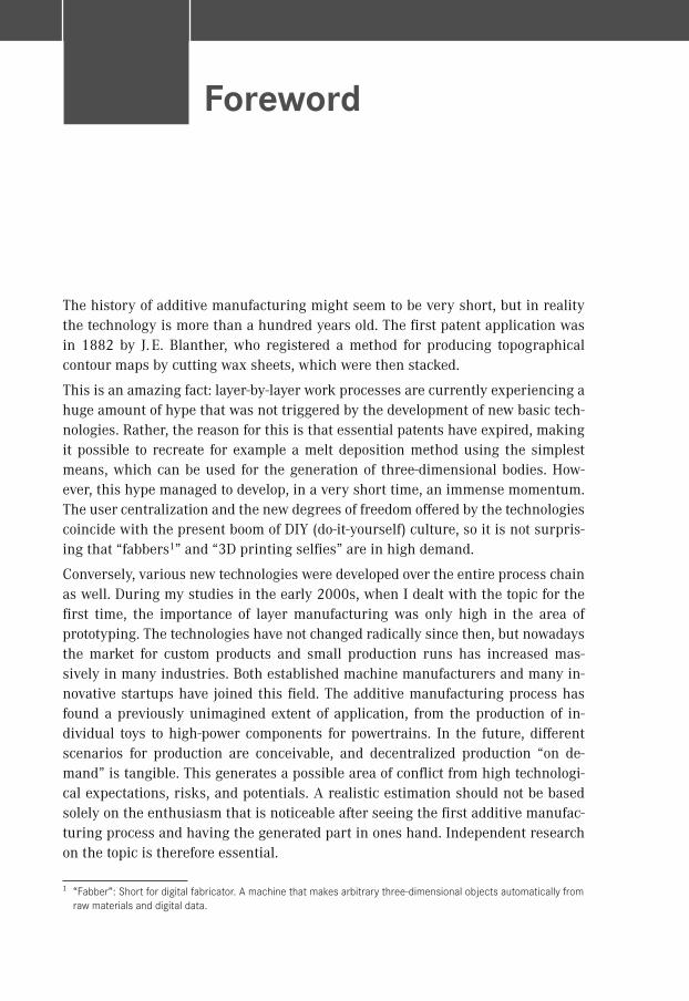
The history of additive manufacturing might seem to be very short, but in reality the technology is more than a hundred years old. The first patent application was in 1882 by J. E. Blanther, who registered a method for producing topographical contour maps by cutting wax sheets, which were then stacked.
This is an amazing fact: layer-by-layer work processes are currently experiencing a huge amount of hype that was not triggered by the development of new basic tech-nologies. Rather, the reason for this is that essential patents have expired, making it possible to recreate for example a melt deposition method using the simplest means, which can be used for the generation of three-dimensional bodies. How-ever, this hype managed to develop, in a very short time, an immense momentum. The user centralization and the new degrees of freedom offered by the technologies coincide with the present boom of DIY (do-it-yourself) culture, so it is not surpris-ing that “fabbers1” and “3D printing selfies” are in high demand.
Conversely, various new technologies were developed over the entire process chain as well. During my studies in the early 2000s, when I dealt with the topic for the first time, the importance of layer manufacturing was only high in the area of prototyping. The technologies have not changed radically since then, but nowadays the market for custom products and small production runs has increased mas-sively in many industries. Both established machine manufacturers and many in-novative startups have joined this field. The additive manufacturing process has found a previously unimagined extent of application, from the production of in-dividual toys to high-power components for powertrains. In the future, different scenarios for production are conceivable, and decentralized production “on de-mand” is tangible. This generates a possible area of conflict from high technologi-cal expectations, risks, and potentials. A realistic estimation should not be based solely on the enthusiasm that is noticeable after seeing the first additive manufac-turing process and having the generated part in ones hand. Independent research on the topic is therefore essential.
1 “Fabber”: Short for digital fabricator. A machine that makes arbitrary three-dimensional objects automatically from raw materials and digital data.
Foreword
VI Foreword
BMW AG ordered the first SLA system in 1989. Thus, BMW AG was the first cus-tomer of a today world-recognized and leading company of laser sintering systems. Over the years, from the first model-making facilities, a center of competence within the Research and Innovation Center (FIZ) evolved, in which various types of practical and basic research are carried out today. In addition to high-quality proto-types for testing and validation of transportation vehicles, materials and processes are being developed, making it possible to realize the potential of layer-by-layer construction. For example, employees working in automotive production are indi-vidually equipped with personalized assembly aids to increase ergonomics and performance in assembly lines.
In this case, the focus of the discussion will be less on the 3D printing processes mentioned in the media, but rather on the highly complex manufacturing ma-chines on which the production is to take place in the future. One such technology is laser sintering (LS), a laser-based unpressurized manufacturing process. How-ever, the coincidence with a “real” sintering process is solely that the generated part cross section will be held near its melting temperature for a long residence time. This is the core process of laser sintering, which has been examined in di-verse ways and is still subject of intensive further research.
As part of my own PhD thesis, I dealt with the time and temperature dependence of the two-phase region, in which melt and solid are present and sharply demar-cated. I had thus the chance to enter one of the many interdisciplinary fields of re-search on additive manufacturing, and am still excited about this topic. Anyone who intends to study or work with laser sintering will not be able to find a lot about such a specialized topic in most of the general books on 3D printing and additive manufacturing. However, as powder-bed-based technologies are established as one of the major additive manufacturing processes, it is essential to present the results of basic research and transfer them to practical use in order to create, for example, as a service provider, viable high-quality parts. The purpose of this book by Man-fred Schmid, one of the recognized specialists in laser sintering, is precisely to give this depth of field without losing sight of the benefits for the user.
Dr.-Ing. Dominik RietzelMay 2015
Dr. Manfred Schmid began his professional career as an apprentice laboratory assistant at Metzeler Kaut-schuk AG in Munich, Germany. After graduation, he studied chemistry at the University of Bayreuth (Ger-many), where he obtained a PhD degree in macro-molecular chemistry. He worked on liquid-crystalline polyurethanes under the guidance of Prof. Dr. C. D. Eisenbach.
After completing his studies, he moved to Switzerland, where he worked for 17 years in industry in various positions in the areas of polymer research and produc-tion as well as material testing and polymer analysis. Polyamides and biopolymers were the focus of these different industry positions.
Since 2008, he leads the research in laser sintering (LS) at Inspire AG, the Swiss Competence Center for Manufacturing Techniques. Inspire AG acts as a transfer institute between universities and the Swiss machine, electro, and metal (MEM) industries.
The focus of his current activities is in the area of new polymer systems for the LS process, the analytical evaluation of such materials, and the qualitative and quantitative improvement of the LS process. He supervises several employees and research projects in this field.
As a guest lecturer, he occasionally lectures on materials science of polymers, manufacturing processes of polymers, and 3D printing at NTB Buchs (Interstate University for Applied Science, Switzerland) and in the University of Applied Science St. Gallen, Switzerland.
The idea for this book emerged from several internal training courses on additive manufacturing conducted at Inspire AG for large industrial companies.
About the Author
91.2 Additive Manufacturing
ate prototypes and models (toys). However, this is sufficient and adequate for the purposes of this sector (design patterns, rapid visualization of new ideas).
Because of substantial advancements in all the technologies mentioned, newly developed methods such as SHS, AKF, and MFJ, and future changes in the cha-racteristics that are not to be excluded, the characteristics of Table 1.1 require constant re-evaluation.
1.2.4� Laser Sintering (LS)
AM-components made as described in Table 1.1, rated by industry standard crite-ria such as mechanical properties, thermal stability, component precision, surface quality, and long-term stability, as well as a few others, should meet the demand in terms of the production of functional parts. Essentially, only laser sintering is qual-ified nowadays. The cohesion of the building materials is carried out by a thermal process that includes the melting of the powder followed by solidifying it into the desired shape.
The LS process is currently considered as the AM process that will be able in the future to permanently cross the border between prototyping and functional com-ponents. This step is considerable because it means that the technology must meet completely different requirements in terms of reproducible quality, process reli-ability, automation of production processes, and other production-typical require-ments.
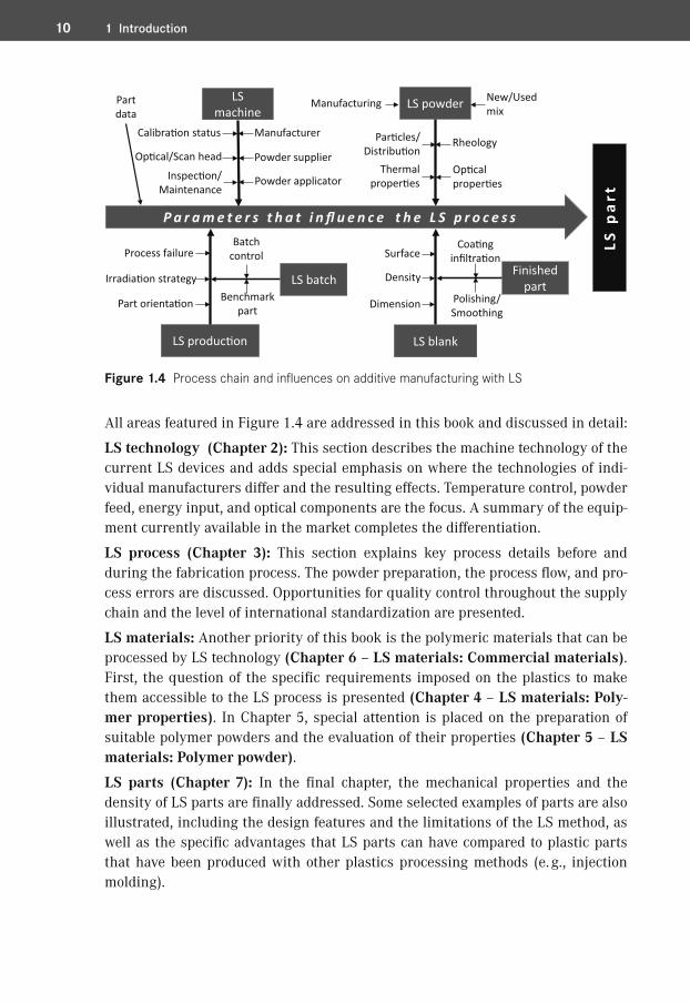
The step from prototype to production part changes the perspective entirely. Both LS parts and the LS process have to be measured in the context of traditional and established production technologies. Only by succeeding at this step can a wide industry acceptance be expected in the future. For this, all levels of the LS process chain must be considered. Figure 1.4 shows schematically the factors that in-fluence the LS process.
10 1 Introduction
LS p
art
LSmachine
LS powder
Par�cles/Distribu�on
Op�calproper�es
LS blank
P a r a m e t e r s t h a t i n fl u e n c e t h e L S p r o c e s s
LS produc�on
LS batch
New/Usedmix
Rheology
Thermalproper�es
Manufacturing
Calibra�on status
Inspec�on/Maintenance
Manufacturer
Irradia�on strategy
Powder applicator
Part orienta�on
Batchcontrol
Benchmarkpart
Density
SurfaceProcess failureFinished
partDimension
Coa�nginfiltra�on
Polishing/Smoothing
Partdata
Powder supplierOp�cal/Scan head
Figure 1.4 Process chain and influences on additive manufacturing with LS
All areas featured in Figure 1.4 are addressed in this book and discussed in detail:
LS technology (Chapter 2): This section describes the machine technology of the current LS devices and adds special emphasis on where the technologies of indi-vidual manufacturers differ and the resulting effects. Temperature control, powder feed, energy input, and optical components are the focus. A summary of the equip-ment currently available in the market completes the differentiation.
LS process (Chapter 3): This section explains key process details before and during the fabrication process. The powder preparation, the process flow, and pro-cess errors are discussed. Opportunities for quality control throughout the supply chain and the level of international standardization are presented.
LS materials: Another priority of this book is the polymeric materials that can be processed by LS technology (Chapter 6 – LS materials: Commercial materials). First, the question of the specific requirements imposed on the plastics to make them accessible to the LS process is presented (Chapter 4 – LS materials: Poly-mer properties). In Chapter 5, special attention is placed on the preparation of suitable polymer powders and the evaluation of their properties (Chapter 5 – LS materials: Polymer powder).
LS parts (Chapter 7): In the final chapter, the mechanical properties and the density of LS parts are finally addressed. Some selected examples of parts are also illustrated, including the design features and the limitations of the LS method, as well as the specific advantages that LS parts can have compared to plastic parts that have been produced with other plastics processing methods (e. g., injection molding).
152.1 Machine Technology
�� 2.1� Machine Technology
2.1.1� Machine Configuration
The market-leader systems from 3D Systems and EOS are structurally similar at their core but differ in details such as powder feed, powder application, optical correction, and the irradiation strategy.
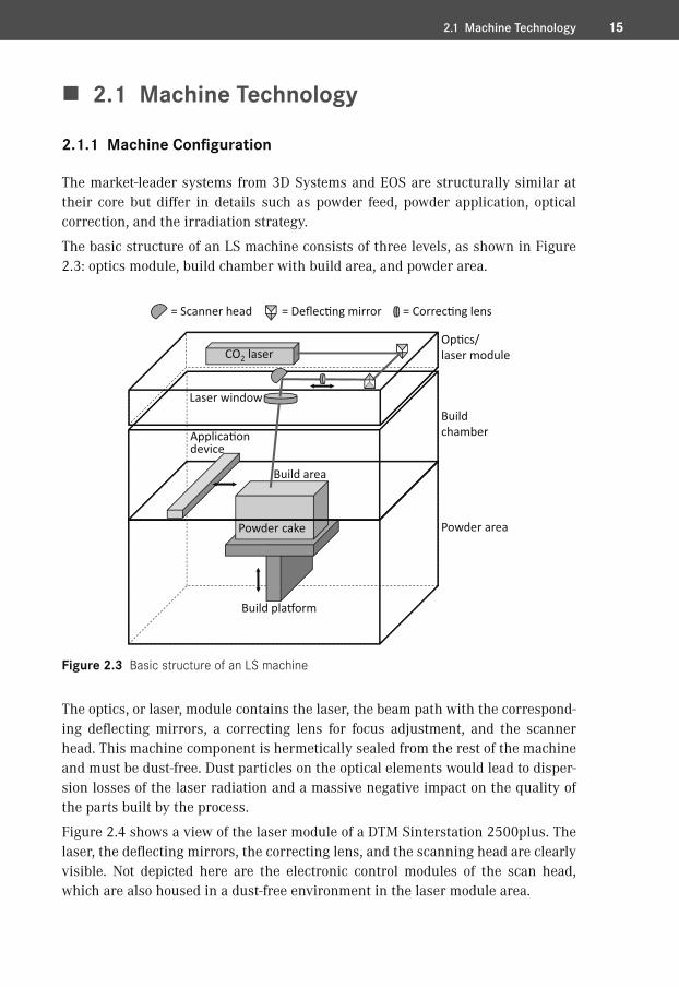
The basic structure of an LS machine consists of three levels, as shown in Figure 2.3: optics module, build chamber with build area, and powder area.
Powder cake
Build pla�orm
Applica�ondevice
= Scanner head = Deflec�ng mirror
Laser window
CO2 laser
Build chamber
Op�cs/laser module
Powder area
Build area
= Correc�ng lens
Figure 2.3 Basic structure of an LS machine
The optics, or laser, module contains the laser, the beam path with the correspond-ing deflecting mirrors, a correcting lens for focus adjustment, and the scanner head. This machine component is hermetically sealed from the rest of the machine and must be dust-free. Dust particles on the optical elements would lead to disper-sion losses of the laser radiation and a massive negative impact on the quality of the parts built by the process.
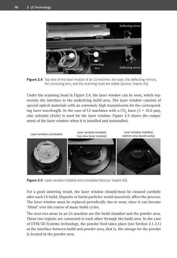
Figure 2.4 shows a view of the laser module of a DTM Sinterstation 2500plus. The laser, the deflecting mirrors, the correcting lens, and the scanning head are clearly visible. Not depicted here are the electronic control modules of the scan head, which are also housed in a dust-free environment in the laser module area.
16 2 LS Technology
Laser Deflec�ng mirror
Deflec�ng mirrorCorrec�ng
lensScanning head
Figure 2.4 Top view of the laser module of an LS machine: the laser, the deflecting mirrors, the correcting lens, and the scanning head are visible [source: Inspire AG]
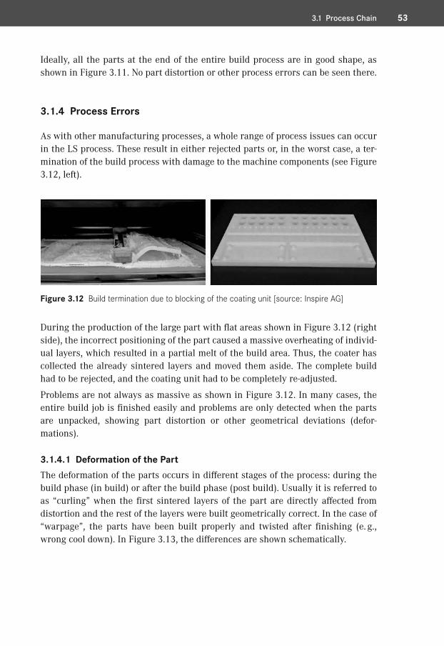
Under the scanning head in Figure 2.4, the laser window can be seen, which rep-resents the interface to the underlying build area. The laser window consists of special optical materials with an extremely high transmission for the correspond-ing laser wavelength. In the case of LS machines with a CO2 laser (l = 10.6 μm), zinc selenide (ZnSe) is used for the laser window. Figure 2.5 shows the compo-nents of the laser window when it is installed and uninstalled.
Laser window uninstalled Laser window installed;top view (laser module)
Laser window installed;bo�om view (build cavity)
Figure 2.5 Laser window installed and uninstalled [source: Inspire AG]
For a good sintering result, the laser window should/must be cleaned carefully after each LS build. Deposits or burnt particles would massively affect the process. The laser window must be replaced periodically due to wear, since it can become “blind” over the course of many build cycles.
The next two areas in an LS machine are the build chamber and the powder area. These two regions are connected to each other through the build area. In the case of DTM/3D Systems technology, the powder feed takes place (see Section 2.1.3.1) at the interface between build and powder area, that is, the storage for the powder is located in the powder area.
533.1 Process Chain
Ideally, all the parts at the end of the entire build process are in good shape, as shown in Figure 3.11. No part distortion or other process errors can be seen there.
3.1.4� Process Errors
As with other manufacturing processes, a whole range of process issues can occur in the LS process. These result in either rejected parts or, in the worst case, a ter-mination of the build process with damage to the machine components (see Figure 3.12, left).
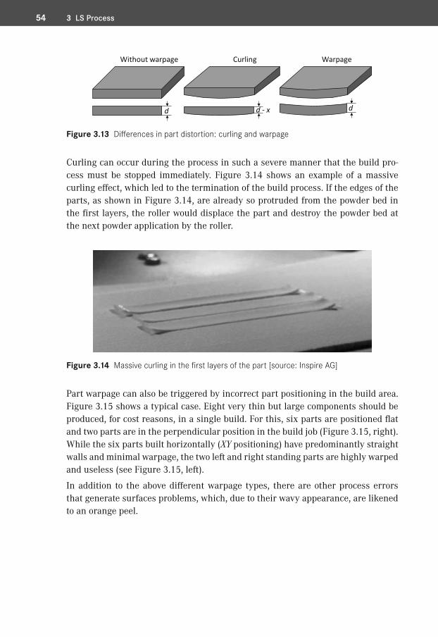
Figure 3.12 Build termination due to blocking of the coating unit [source: Inspire AG]
During the production of the large part with flat areas shown in Figure 3.12 (right side), the incorrect positioning of the part caused a massive overheating of individ-ual layers, which resulted in a partial melt of the build area. Thus, the coater has collected the already sintered layers and moved them aside. The complete build had to be rejected, and the coating unit had to be completely re-adjusted.
Problems are not always as massive as shown in Figure 3.12. In many cases, the entire build job is finished easily and problems are only detected when the parts are unpacked, showing part distortion or other geometrical deviations (defor-mations).
3.1.4.1� Deformation of the PartThe deformation of the parts occurs in different stages of the process: during the build phase (in build) or after the build phase (post build). Usually it is referred to as “curling” when the first sintered layers of the part are directly affected from distortion and the rest of the layers were built geometrically correct. In the case of “warpage”, the parts have been built properly and twisted after finishing (e. g., wrong cool down). In Figure 3.13, the differences are shown schematically.
54 3 LS Process
d dd - x
Without warpage Curling Warpage
Figure 3.13 Differences in part distortion: curling and warpage
Curling can occur during the process in such a severe manner that the build pro-cess must be stopped immediately. Figure 3.14 shows an example of a massive curling effect, which led to the termination of the build process. If the edges of the parts, as shown in Figure 3.14, are already so protruded from the powder bed in the first layers, the roller would displace the part and destroy the powder bed at the next powder application by the roller.
Figure 3.14 Massive curling in the first layers of the part [source: Inspire AG]
Part warpage can also be triggered by incorrect part positioning in the build area. Figure 3.15 shows a typical case. Eight very thin but large components should be produced, for cost reasons, in a single build. For this, six parts are positioned flat and two parts are in the perpendicular position in the build job (Figure 3.15, right). While the six parts built horizontally (XY positioning) have predominantly straight walls and minimal warpage, the two left and right standing parts are highly warped and useless (see Figure 3.15, left).
In addition to the above different warpage types, there are other process errors that generate surfaces problems, which, due to their wavy appearance, are likened to an orange peel.
96 4 LS Materials: Polymer Properties
narrow, widedistribu�on
symmetrical, asymmetricaldistribu�on
unimodal, bimodaldistribu�on
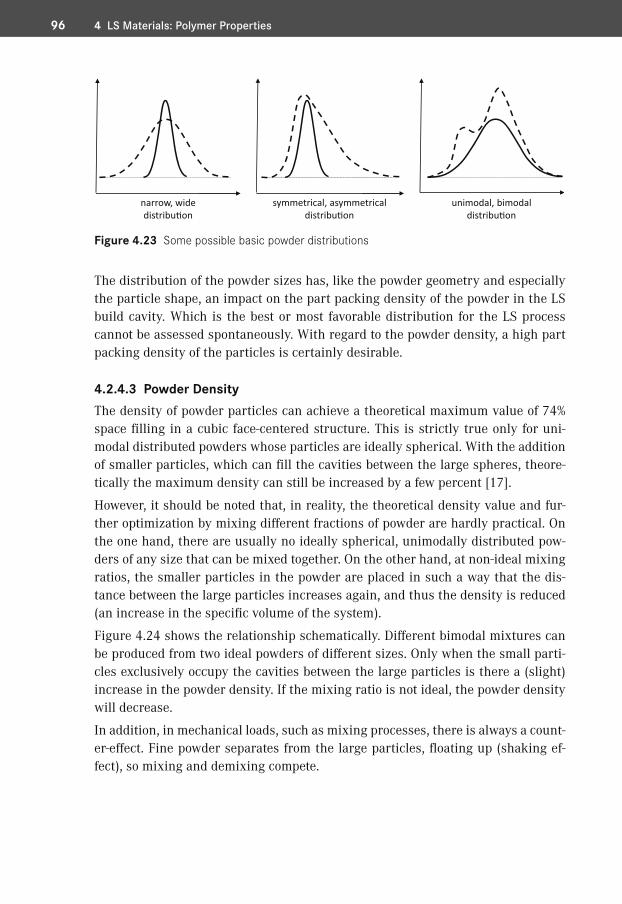
Figure 4.23 Some possible basic powder distributions
The distribution of the powder sizes has, like the powder geometry and especially the particle shape, an impact on the part packing density of the powder in the LS build cavity. Which is the best or most favorable distribution for the LS process cannot be assessed spontaneously. With regard to the powder density, a high part packing density of the particles is certainly desirable.
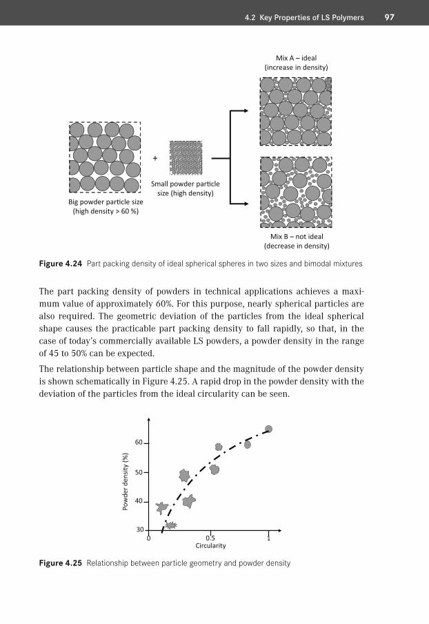
4.2.4.3� Powder DensityThe density of powder particles can achieve a theoretical maximum value of 74% space filling in a cubic face-centered structure. This is strictly true only for uni-modal distributed powders whose particles are ideally spherical. With the addition of smaller particles, which can fill the cavities between the large spheres, theore-tically the maximum density can still be increased by a few percent [17].
However, it should be noted that, in reality, the theoretical density value and fur-ther optimization by mixing different fractions of powder are hardly practical. On the one hand, there are usually no ideally spherical, unimodally distributed pow-ders of any size that can be mixed together. On the other hand, at non-ideal mixing ratios, the smaller particles in the powder are placed in such a way that the dis-tance between the large particles increases again, and thus the density is reduced (an increase in the specific volume of the system).
Figure 4.24 shows the relationship schematically. Different bimodal mixtures can be produced from two ideal powders of different sizes. Only when the small parti-cles exclusively occupy the cavities between the large particles is there a (slight) increase in the powder density. If the mixing ratio is not ideal, the powder density will decrease.
In addition, in mechanical loads, such as mixing processes, there is always a count-er-effect. Fine powder separates from the large particles, floating up (shaking ef-fect), so mixing and demixing compete.
974.2 Key Properties of LS Polymers
+
Big powder par�cle size(high density > 60 %)
Small powder par�clesize (high density)
Mix A – ideal(increase in density)
Mix B – not ideal(decrease in density)
Figure 4.24 Part packing density of ideal spherical spheres in two sizes and bimodal mixtures
The part packing density of powders in technical applications achieves a maxi-mum value of approximately 60%. For this purpose, nearly spherical particles are also required. The geometric deviation of the particles from the ideal spherical shape causes the practicable part packing density to fall rapidly, so that, in the case of today’s commercially available LS powders, a powder density in the range of 45 to 50% can be expected.
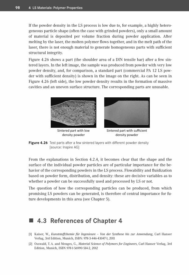
The relationship between particle shape and the magnitude of the powder density is shown schematically in Figure 4.25. A rapid drop in the powder density with the deviation of the particles from the ideal circularity can be seen.
Circularity0 0.5 1
30
Pow
derd
ensit
y(%
)
60
50
40
Figure 4.25 Relationship between particle geometry and powder density
98 4 LS Materials: Polymer Properties
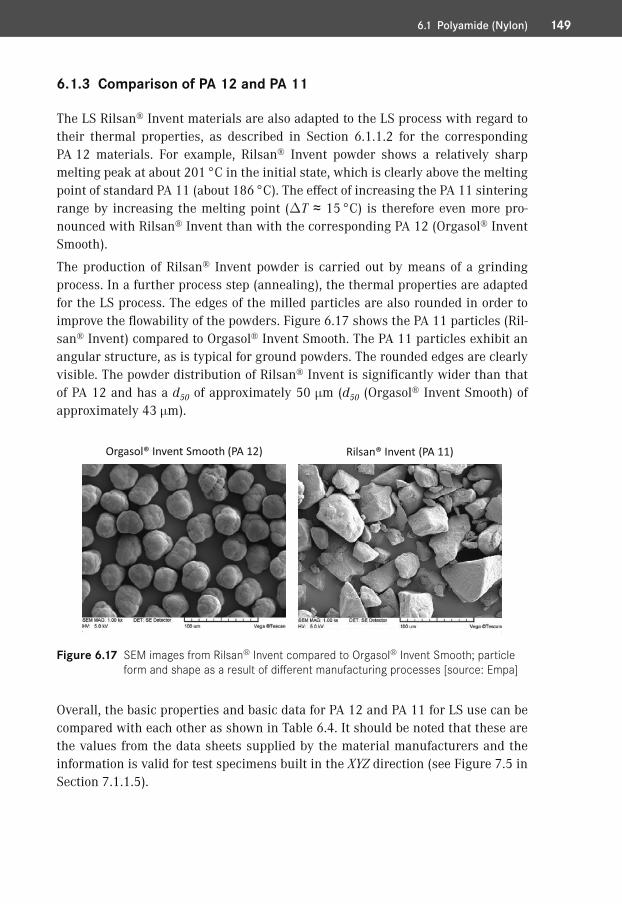
If the powder density in the LS process is low due to, for example, a highly hetero-geneous particle shape (often the case with grinded powders), only a small amount of material is deposited per volume fraction during powder application. After melting by the laser, the molten polymer flows together, and in the melt path of the laser, there is not enough material to generate homogeneous parts with sufficient structural integrity.
Figure 4.26 shows a part (the shoulder area of a DIN tensile bar) after a few sin-tered layers. In the left image, the sample was produced from powder with very low powder density, and, for comparison, a standard part (commercial PA 12 LS pow-der with sufficient density) is shown in the image on the right. As can be seen in Figure 4.26 (left side), the low powder density results in the formation of massive cavities and an uneven surface structure. The corresponding parts are unusable.
Sintered part with lowdensity powder
Sintered part with sufficientdensity powder
Figure 4.26 Test parts after a few sintered layers with different powder density [source: Inspire AG]
From the explanations in Section 4.2.4, it becomes clear that the shape and the surface of the individual powder particles are of particular importance for the be-havior of the corresponding powders in the LS process. Flowability and fluidization based on powder form, distribution, and density: these are decisive variables as to whether a powder can be successfully used and processed by LS or not.
The question of how the corresponding particles can be produced, from which promising LS powders can be generated, is therefore of central importance for fu-ture developments in this area (see Chapter 5).
�� 4.3�References of Chapter 4
[1] Kaiser, W., Kunststoffchemie für Ingenieure – Von der Synthese bis zur Anwendung, Carl Hanser Verlag, 3rd Edition, Munich, ISBN: 978-3-446-43047-1, 2011
[2] Osswald, T. A. and Menges, G., Material Science of Polymers for Engineers, Carl Hanser Verlag, 3rd Edition, Munich, ISBN 978-1-56990-514-2, 2012
1496.1 Polyamide (Nylon)
6.1.3� Comparison of PA 12 and PA 11
The LS Rilsan® Invent materials are also adapted to the LS process with regard to their thermal properties, as described in Section 6.1.1.2 for the corresponding PA 12 materials. For example, Rilsan® Invent powder shows a relatively sharp melting peak at about 201 °C in the initial state, which is clearly above the melting point of standard PA 11 (about 186 °C). The effect of increasing the PA 11 sintering range by increasing the melting point (DT ≈ 15 °C) is therefore even more pro-nounced with Rilsan® Invent than with the corresponding PA 12 (Orgasol® Invent Smooth).
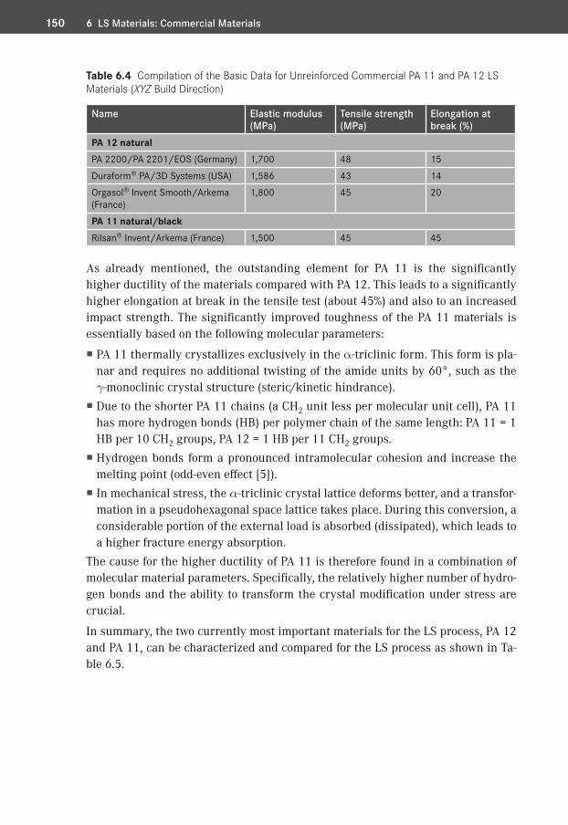
The production of Rilsan® Invent powder is carried out by means of a grinding process. In a further process step (annealing), the thermal properties are adapted for the LS process. The edges of the milled particles are also rounded in order to improve the flowability of the powders. Figure 6.17 shows the PA 11 particles (Ril-san® Invent) compared to Orgasol® Invent Smooth. The PA 11 particles exhibit an angular structure, as is typical for ground powders. The rounded edges are clearly visible. The powder distribution of Rilsan® Invent is significantly wider than that of PA 12 and has a d50 of approximately 50 mm (d50 (Orgasol® Invent Smooth) of approximately 43 mm).
Rilsan® Invent (PA 11)Orgasol® Invent Smooth (PA 12)
Figure 6.17 SEM images from Rilsan® Invent compared to Orgasol® Invent Smooth; particle form and shape as a result of different manufacturing processes [source: Empa]
Overall, the basic properties and basic data for PA 12 and PA 11 for LS use can be compared with each other as shown in Table 6.4. It should be noted that these are the values from the data sheets supplied by the material manufacturers and the information is valid for test specimens built in the XYZ direction (see Figure 7.5 in Section 7.1.1.5).
150 6 LS Materials: Commercial Materials
Table 6.4 Compilation of the Basic Data for Unreinforced Commercial PA 11 and PA 12 LS Materials (XYZ Build Direction)
Name Elastic modulus (MPa)
Tensile strength (MPa)
Elongation at break (%)
PA 12 naturalPA 2200/PA 2201/EOS (Germany) 1,700 48 15Duraform® PA/3D Systems (USA) 1,586 43 14Orgasol® Invent Smooth/Arkema (France)
1,800 45 20
PA 11 natural/blackRilsan® Invent/Arkema (France) 1,500 45 45
As already mentioned, the outstanding element for PA 11 is the significantly higher ductility of the materials compared with PA 12. This leads to a significantly higher elongation at break in the tensile test (about 45%) and also to an increased impact strength. The significantly improved toughness of the PA 11 materials is essentially based on the following molecular parameters:
� PA 11 thermally crystallizes exclusively in the a-triclinic form. This form is pla-nar and requires no additional twisting of the amide units by 60°, such as the g-monoclinic crystal structure (steric/kinetic hindrance).
� Due to the shorter PA 11 chains (a CH2 unit less per molecular unit cell), PA 11 has more hydrogen bonds (HB) per polymer chain of the same length: PA 11 = 1 HB per 10 CH2 groups, PA 12 = 1 HB per 11 CH2 groups.
� Hydrogen bonds form a pronounced intramolecular cohesion and increase the melting point (odd-even effect [5]).
� In mechanical stress, the a-triclinic crystal lattice deforms better, and a transfor-mation in a pseudohexagonal space lattice takes place. During this conversion, a considerable portion of the external load is absorbed (dissipated), which leads to a higher fracture energy absorption.
The cause for the higher ductility of PA 11 is therefore found in a combination of molecular material parameters. Specifically, the relatively higher number of hydro-gen bonds and the ability to transform the crystal modification under stress are crucial.
In summary, the two currently most important materials for the LS process, PA 12 and PA 11, can be characterized and compared for the LS process as shown in Ta-ble 6.5.
1516.1 Polyamide (Nylon)
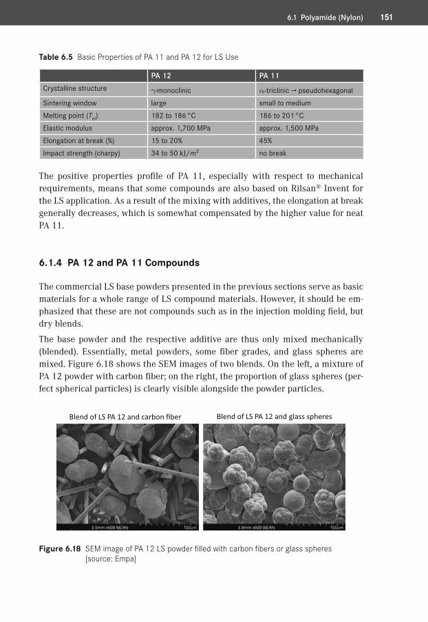
Table 6.5 Basic Properties of PA 11 and PA 12 for LS Use
PA 12 PA 11Crystalline structure g-monoclinic a-triclinic → pseudohexagonalSintering window large small to mediumMelting point (Tm) 182 to 186 °C 186 to 201 °CElastic modulus approx. 1,700 MPa approx. 1,500 MPaElongation at break (%) 15 to 20% 45%Impact strength (charpy) 34 to 50 kJ/m2 no break
The positive properties profile of PA 11, especially with respect to mechanical requirements, means that some compounds are also based on Rilsan® Invent for the LS application. As a result of the mixing with additives, the elongation at break generally decreases, which is somewhat compensated by the higher value for neat PA 11.
6.1.4� PA 12 and PA 11 Compounds
The commercial LS base powders presented in the previous sections serve as basic materials for a whole range of LS compound materials. However, it should be em-phasized that these are not compounds such as in the injection molding field, but dry blends.
The base powder and the respective additive are thus only mixed mechanically (blended). Essentially, metal powders, some fiber grades, and glass spheres are mixed. Figure 6.18 shows the SEM images of two blends. On the left, a mixture of PA 12 powder with carbon fiber; on the right, the proportion of glass spheres (per-fect spherical particles) is clearly visible alongside the powder particles.
Blend of LS PA 12 and carbon fiber Blend of LS PA 12 and glass spheres
Figure 6.18 SEM image of PA 12 LS powder filled with carbon fibers or glass spheres [source: Empa]
Symbols
3D complexity 23D-P 63D printing 3, 63D Systems 14, 29, 1273MF 436-aminohexanoicacid 129a-triclinic 150γ and α modification 140
A
A-A/B-B and A-B polyamides 129absorbing ink printing 7absorption 91absorption coefficient 88accumulation 93action checklist 58active chain ends 66additive manufacturing 2adhesion 5Advanced Laser Materials (ALM) 127,
152Advanced Manufacturing Research
Center 188aerospace 187aerospace industry 181aging at elevated temperatures 174air conditioning system for driving
simulator test 183AM business models 186AM-compatible design 181America Makes 187
AMF 43amidation 66amide group 130amine group 130amorphous 68AM roadmaps 187AM standardization activities 63Andrew number 20, 49anisotropy of the part properties 171ARBURG polymer freeforming 7architectural model 8area coverage 94, 117armaments industry 181Aspect 32aspect ratio 94, 117Association of German Engineers 62,
110ASTM F42 62ASTM F2792-12a 2automotive fluids 174automotive industry 181avalanche angle 123average molecular weight 72, 102
B
balling effect 86beam path 28Belgium 187benchmark parts 59BET method 116B. F. Goodrich 125blade and powder cartridge 25
Index
196 Index
blend materials 173Blue Printer 7boundary 78brand names 126brittle fracture 162build area 17build cavity 18, 47build chamber parameters 48build height in Z direction 56build job 39, 42, 43build process 44build volume 34bulk density 120buoyancy 166business model 4, 5, 186
C
calibration 19caprolactam 129CarbonMide® 172carboxyl group 130casting process 8cavities 166, 181cavity 43characterization matrix for additive
manufacturing 6characterization of surfaces 116chemical bond 65chemical reaction 5chemical structure 68China 187circularity 94, 117clamping and gripping technology
186coalescence 46coalescence of Duraform® PA 86coating 179coextrusion 105cohesive 93color and light fastness 180colors 180color saturation 166commercial materials 125commodities 129
comparison of mechanical properties 164
comparison of PA 12 and PA 11 149complexity 4, 181component properties 7compressed air 52computer tomography 108, 166concave curvature 26cone-plate rheometer 84contactless optical measurement
techniques 176continuous use temperature 154contour of the surface 176control 18control checks 109control of the powder state 41cool down and part extraction 51cooling 40cooling down of the LS build 80coordinate system 171core temperature of the powder cake
51corrective lens 28cost per unit 4covalent bond 65crack initiators 166cracks in the powder bed 56creep behavior 174cross-contamination 41crosslinking 65cryogenic milling 104crystallization 75crystallization aids 79crystallization behavior in the LS process
79crystallization enthalphy 80crystallization in the LS process 77crystallization kinetics 82crystallization nuclei 168crystal size 78crystal structure 139curling 54customization 186customized industrial grippers 186cyclone separator 107
197Index
D
decomposition point 69deformation of the part 53degree of crystallinity 68degree of particle melt 79dental corrections 186dental prosthetic 4design features 60Desktop Manufacturing 125determination of powder flowability 119determination of the sintering window
110determination of the viscosity number
115differential scanning calorimetry 110diffuse reflection 90dimensional stability of the parts 60diode laser 36directional orientation and part
identification 171distribution curves for powders 117DMA 174double blade 25drilling guides 4drop extrusion 108droplet matrix morphology 105dry blends 131, 151DTM 14DTM clone 33ductility 150Duraform® FLEX 157Duraform® HST 111, 172Duraform® PA 130dust particle 15
E
economic fabrication 3effects of the post-condensation reaction
145eGrip 186elastic modulus 144elastomeric materials 156elastomers 65electrical conductivity 179
electronics 181Electro Optical Systems (EOS) 14, 31,
127electrostatic shielding 179elongation at break 77, 144, 150, 173emulsion and suspension polymerization
102end groups 143energy absorption time 22engineering polymers 128England 187enthalpy of fusion 80EOSINT 31EOSINT P 800 31, 154EOS PPM system 61equilibrium reaction 142esterification 66estimation of the LS powder
processability 119ether and keto groups 153evolution of the LS technology 13ExcelTec 127, 152extension of the polymer chains 144extrinsic powder properties 115extrinsic properties 74extrusion conditions 105
F
FAR-25 (25.853) 154Farsoon 33FDM® devices 8FDM® industrial printers 8fiber grade 151fiber laser 33fibers 131filament extrusion 6fine needle tip 176fine particles 42, 93, 118fine powder 133fingerprint range 88finishing 177, 178finishing process 52first order physical transformation 110flame retardant materials 154
198 Index
flat surface 43flowability 95flowability of powders 93flow behavior 93flowing point 69flowing point of the polymer 70fluidization 25, 93fluidized height 123focal plane 28focus correction 28form factors of the cavities 167FORMIGA 31freedom of design 181free-flowing behavior 95, 118Frenkel/Eshelby model 86fresh powder 18F-Theta lens 29fumed silica 93functional end groups 66functional integration 183functionality driven design 4functional parts 8furniture industry 181fused deposition modeling, FDM 6
G
Gel Permeation Chromatography 115, 142
GelSight 176general cleanliness 58general quality actions 57geometric freedom 3Gibbs-Thomson equation 140glass spheres 131, 151glass transition temperature 69grain size distribution 95gravity 86gripper fingers 186group or deformation vibration 89
H
halogenated flame retardants 154Hampel estimator 121
hand finishing 177hard segments 65Hausner factor 93, 120hearing aids 186heat capacity 80, 110heat exposure 145heating 44heating and cooling rate 76heat radiation 80, 82heat radiation effects 80heat resistance 152heat source 18Hewlett Packard (HP) 7highly porous powders 116Hofmann Medea 1500 SLS 37hold layer-time 44hollow spheres 107homogeneous particle size distribution
134homogeneous part properties 168homogenization of the melt 79Huazhong University 37humidity 23hydrogen bonds 130, 150
I
impact strength 77, 150incomplete coalescence 70incorrect positioning of the part 53induce cracking 166industry standards for additive
manufacturing 64infrared spectrum 89inhomogeneous crystallization 51initiator 102inkjet UV printing 6input control 93integrating sphere 90interlaboratory test 120internal stresses 83intrinsic properties 74irradiation vector 49IR radiator 19ISO TC 261 62
199Index
isothermal laser sintering 129isotropic part properties 51isotropy 77
J
jewelry industry 181
K
kinetic energy 104
L
Lambert-Beer’s law 88lamellar thickness 140laser diffraction method 117laser energy input 20laser irradiation 51laser module 15laser overlap 21laser power 21laser sintering, LS 6, 9laser spot 28laser spot shape 29laser window 16laurinlactam 103laurolactam 130, 141layer adhesion 144layer boundaries 144layer-by-layer fusion 13layer delamination 56, 144layer manufacturing technologies 2Le Chatelier’s principle 67lifestyle and fashion 187lifestyle products 180lightweight structures 181linearization of the polymer coil 72liquid nitrogen 104list of measures for quality control
58living anionic polymerization 103logistics 5long-term stability 174lost model 8
LS – build parameters 164 – coloring parts 179 – compound materials 151 – history 14 – homogeneous parts 168 – material portfolio 11 – material suppliers 126 – materials table 191 – parts 161 – process 9, 13, 39 – processability 133 – process chain 9 – process errors 56 – sintering window 75 – technology 10, 13
M
machine configuration 15machine logbook 58machine market 29machine service 58machine technology 15manufacturing driven design 4manufacturing technology 1market shares 128Massachusetts Institute of Technology
176material and process matrix 5material assortment 127material classes 126material optimization by means of fillers
172material portfolio 126material selection 11matrix polymer 105maximum tensile strength 162mechanical grinding 104mechanical properties 7, 162medical technology 181medicine/dentistry 187melt flow index 41, 112melting 75melting in the LS process 79
200 Index
melting point 47, 69melt spinning 108melt viscosity 41, 55, 84, 112melt volume rate 112metal and non-metal oxide 89metal powders 131, 151metastable 75MFI control points 41microscope with a heating table 86milling 104mirror speed of the scanning head 50mixture of materials 41model 8modeling the processes in the sintering
window 82model/prototype construction 182moisture content 111mold cooling 79molecular weight 68, 71, 141, 143,
147molecular weight distribution 114monoclinic (pseudohexagonal) 139morphology 68Multi Jet Fusion®, MJF 7multijet printing, MJP 6multi-zone heater 18MVR measurements 113MVR/MFI 112
N
name of polyamides 129National Additive Manufacturing
Innovation Institute 187national AM special programs 187new PA 12 LS powder 40Newtonian fluid 84nitrogen 24non-destructive determination of the
porosity 166non-isothermal crystallization 77Norge Systems 36number average molecular weight 114number distribution 117number of repeat units 144
numerical simulation 82nylon (polyamide) 125
O
odd-even effect 150oligomer 115onset of the melting point 77optical components 28optical microscopy analysis 117optical properties 87optimal parameter sets 61orange peel 55Orgasol® Invent Smooth 102, 130oven aging 146overflow powder 40overheating of individual layers 53overlapping of laser tracks 49oxidation 18, 51oxidative degradation reaction 146
P
PA 11 149PA 12 and PA 11 compounds 151PA 12 base powders 131PA 12 powder with carbon fiber 151parallel plate viscometer 84part assembly 43part collision 43part data 11part density 165part distortion 54part distribution 44partially melted powder 168partial melt of the build area 56partial pressure difference 142particle coalescence 87particle geometry 97particle shape 94, 115particle size distribution 95particle surface 94part packing density 40, 96, 97part precision 8part properties 162
201Index
Part-Property-Management (PPM) 61part surfaces 174parts yellowing 56penetration depth of the radiation 90performance parameters 34physical network points 65plasticizer content 111plastic measuring cylinder 120plastic pyramid 128polishing 179polyacrylate 102polyamide 6 (PA 6) 105, 152polyamide 11 (PA 11) 105, 148polyamide 12 (PA 12) 130polyamide (nylon) 129polybutylene terephthalate 125polycarbonate 71, 125polycondensation reaction 67polydispersity index 114polyether ketone 153polyethylene 155PolyJet® modeling, PJM 6polymer and LS market in comparison
128polymer chains with open ends 141polymerization 66polymer particle 91polymer powders 101polymer processing 70polymer properties 65polymers sensitive to hydrolysis 113polymethylmethacrylate 71polymorphism 139polyphosphinate 155polypropylene 155polystyrene 102, 156polyvinyl chloride 102pores 166porosity determination 167post-condensation 84, 141, 144post-condensation of PA 12 in solid state
142post-condensation reaction 141post-processing 52powder agglomeration 56
powder aging 145powder application 24powder behavior 91powder cake 51powder coating 101powder conditioning 23powder density 27, 96powder distribution 115, 131, 147powder feed 22powder flowability 24, 118powder flow in the LS process 40powder funnel 120powder mixture 40powder particle 147powder preparation 40powder recycling 146powder rheology 92powder “short-feed” 56powder state 40, 109, 119powder supply 22powder surrounding 81precipitation from solutions 103precipitation process 103precipitation process from an ethanol
solution 103precision and accuracy 60pre-heating 39primary processing 70primary shaping 1primary shaping process 164Primepart® ST (PEBA 2301) 157process additives 103process chain 5process control 39, 81process cycle 44process diagram for the LS method 40process errors 53processing temperature 69process sequence 46process temperature 83product development 8production of LS powders 101, 106production planning 58production technology 39productivity 34
202 Index
product personalization 4professional finishing 179proper design 172properties matrix of the LS materials
173properties required for LS polymers 73property combination of PA 12 147proportion of large particles 95protective suits 185ProX™ 500 14Push™ process 178
Q
quality assurance 57, 109quality certificate 59quality control 57quality costs 61quality data 11quality management 59quality measures 57quality of the part data 42
R
radical and ionic polymerization 66radical chain reaction 102radical formation 146RaFaEl 32Ra (mean roughness) 175Rapid Expansion of Supercritical Solution
109rapid prototyping 2raw materials for paint 103recycled powder 41reduction of part lists 185reflection 87, 91reflection measurement 89reflector holder 184reinforced materials 127rejected part 53repeatability 121reproducibility 121residual build 40residual content 114
residual crystallinity 169residual porosity 167retention sample 58, 60revolution powder analysis 122rheology of the polymer melt 83Rilsan® Invent 149ring-opening polyaddition 130robotic gripper 4RoHS directive 154roller coater 26roller surface 27rotational speed 123roughness determination 176roughness parameters 176rounding of the particles 104roundness 94round-robin test 121Rz (maximum roughness) 175
S
sacrificial parts 60scanning electron micrograph 108scanning head mirror 49scan speed of the laser beam 21scattering phenomena 87schematic structure of polymers 66Schleiss RPTech 42secondary valence forces 130sedimentation time 123selective heat sintering 7semi-crystalline 68SEMplice 32serial parts 161set parameters 49shaking effect 96shape of the particle 117shear 71short-term load – tensile test 162
sieve analysis 117simulation of the degree of solidification
82simulation of the LS processes 80simulation of thermal process 83
203Index
Singapore 187single blade 25sintered necks 71sintering cycle 47sintering window 75Sinterline™ 152SinterStation 14Sintratec 35skin contact 180soft segments 65solidity 94solid-liquid state 82solvents 178spatial-direction-dependent part
properties 172spatial directions 171spatial orientation 171special material 49specific surface area 116spectacle frames 179sphericity 94, 103, 116, 133spherulite boundaries 78spherulitic crystal structure 77sports and racetrack applications 152sports equipment industry 181spray drying 107stabilizers 146stair-step effect 175standard deviation 121standardization 62standards and recommendations 63standards bodies 62standards committees at country level
62state of equilibrium 24status report “Additive Manufacturing
Process” 181step-growth reaction 66stereolithography, SL 6STL – file 42 – format 42
stock powder 23strategy of part irradiation 49streaming 56
structural body 71structural density 84structure of an LS machine 15sublimation 155subtractive methods 2supercooled melt 85supporting structure 43support structure requirements 7surface defects 55surface finishing 177surface fractal 123surface heater 45surface quality 8, 9, 11surface roughness 116surface roughness of LS parts 134surface temperature 19surface tension 71, 84, 86, 87system status 58system supplier 61
T
tacticity 68tactile/contacting measurement
176tangential velocity 26tapped density 120technological maturity 161technology driver 3technology maturation 7temperature control 17, 18temperature jump in the laser track
76tensile strength 77, 144termination of the build process 53test and comparison parts 59test parts 58TGA measurement curve 111thermal – analysis 110 – behavior 69 – conductivity 80 – equilibrium 44 – load 146 – properties 8, 74, 134, 147
204 Index
– shock 45 – transitions of amorphous and semi-crystalline polymers 70
thermo-balance 111thermogravimetry 111thermo-oxidative damage 104thermoplastic 65thermoplastic elastomers 65, 105, 122,
157thermoplastic polyurethane 105, 122,
157thermoset 65thread 43titanium oxide 89tool 3tool and mold making 181translational velocity 26transmission 91troweling 178
U
uncontrolled part growth 56undercuts 3University of Austin 125University of Sheffield 178un-sintered powder 40U.S. President Barack Obama 187UV exposure 146
V
vapor phase 178Varia 3D 34variation in the irradiation 51variation of laser power 169varnishing 179VDI 181vehicle and mobility 187
vibrations of the powder coaters 175vibratory grinding 178viscoelastic properties 85viscosity 71viscosity curve 71, 84viscous behavior 84visible laser scanning lines 175voids 166volume build rate 34volume distribution 117
W
warpage 54“wash out” 56wash-out effects 175water absorption 152water resistance 179wax printing 6weight average molecular weight 114weld lines 31white pigment 89wide angle X-ray scattering 139Windform 127, 152
X
X-ray diffraction (WAXS) 139XYZ build direction 150
Y
yellowing of the surface 51yield stress 77
Z
zero shear viscosity 72, 83zinc selenide (ZnSe) 16