Embed Size (px)
Citation preview

To order more books:
Call 1-800-529-5517 or
Visit www.emastercam.com or
Contact your Mastercam dealer
Mill Level 3 Training Tutorial

Mastercam X7 Mill Level 3 Training Tutorial
Copyright: 1998 - 2013 In-House Solutions Inc. All rights reserved
Software: Mastercam X7
Author: Mariana Lendel
ISBN: 978-1-926955-77-3
Date: May 13, 2013
Notice
In-House Solutions Inc. reserves the right to make improvements to this manual at any time and without notice.
Disclaimer Of All Warranties And Liability
In-House Solutions Inc. makes no warranties, either express or implied, with respect to this manual or with respect to the software described in this manual, its quality, performance, merchantability, or fitness for any praticular purpose. In-House Solutions Inc. manual is sold or licensed "as is." The entire risk as to its quality and performance is with the buyer. Should the manual prove defective following its purchase, the buyer (and not In-House Solutions Inc., its distributer, or its retailer) assumes the entire cost of all necessary servicing, repair, of correction and any incidental or consequential damages. In no event will In-House Solutions Inc. be liable for direct, indirect, or consequential damages resulting from any defect in the manual, even if In-House Solutions Inc. has been advised of the possibility of such damages. Some jurisdictions do not allow the exclusion or limitation of implied warranties or liability for incidental or consequential damages, so the above limitation or exclusion may not apply to you.
CopyrightsThis manual is protected under International copyright laws. All rights are reserved. This document may not, in whole or part, be copied, photographed, reproduced, translated or reduced to any electronic medium or machine readable form without prior consent, in writing, from In-House Solutions Inc.
TrademarksMastercam is a registered trademark of CNC Software, Inc.
Microsoft, the Microsoft logo, MS, and MS-DOS are registered trademarks of Microsoft Corporation; Windows 7 and Windows 8 are registered trademarks of Microsoft Corporation.

TABLE OF CONTENTS
Table of Contents
GETTING STARTED
Getting Started ........................................................................................................... 1
TutorialsTutorial #1 - Surface Rough Pocket, Surface Finish Shallow & Surface Finish Contour.........................15
Tutorial #2 - Surface Rough Pocket, Surface Finish Parallel & Surface Finish Pencil .............................97
Tutorial #3 - Stock Model, Surface HS Rest Roughing & Radial & Surface Finish Blend......................179
Tutorial #4 - Surface HS OptiArea, Surface HS OptiRest, Surface HS Hybrid & Surface HS Scallop.....295
Tutorial #5 - Surface HS Core Roughing, Scallop, Spiral & Waterline..................................................461
Tutorial #6 - Surface HS OptiCore, Horizontal, Waterline, Raster & Pencil.........................................643
Tutorial #7 - Surface HS OptiArea, Rest Roughing, Surface Finish Scallop, Leftover & Project ..........743 Quiz Answers .......................................................................................................... 879
Mill Level 3 Training Tutorial

TABLE OF CONTENTS
Mill Level 3 Training Tutorial
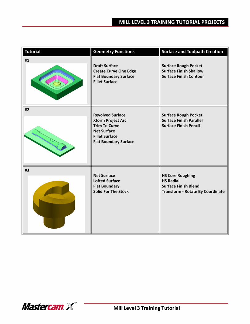
MILL LEVEL 3 TRAINING TUTORIAL PROJECTS
Tutorial Geometry Functions Surface and Toolpath Creation
#1Draft Surface Create Curve One EdgeFlat Boundary SurfaceFillet Surface
Surface Rough PocketSurface Finish ShallowSurface Finish Contour
#2Revolved SurfaceXform Project ArcTrim To CurveNet SurfaceFillet Surface Flat Boundary Surface
Surface Rough PocketSurface Finish ParallelSurface Finish Pencil
#3Net SurfaceLofted SurfaceFlat BoundarySolid For The Stock
HS Core RoughingHS Radial Surface Finish BlendTransform - Rotate By Coordinate
Mill Level 3 Training Tutorial
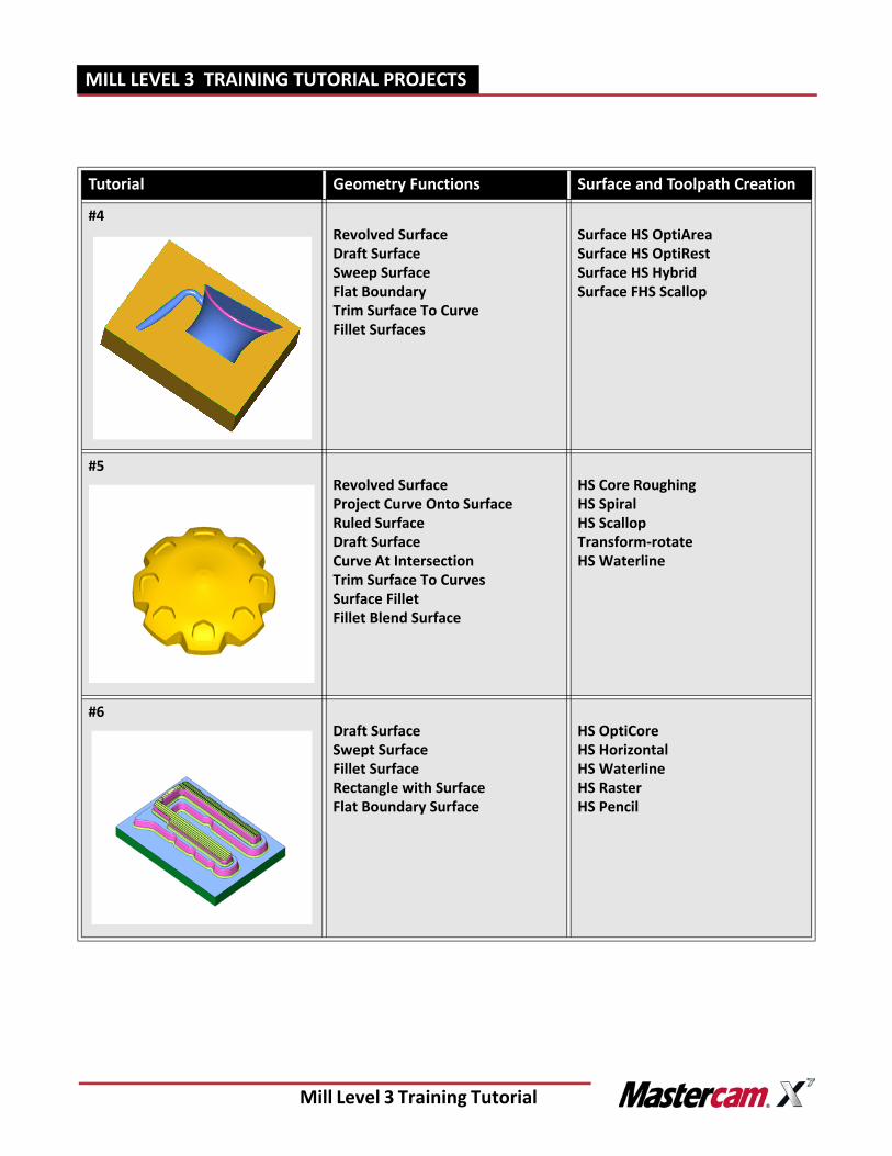
MILL LEVEL 3 TRAINING TUTORIAL PROJECTS
Tutorial Geometry Functions Surface and Toolpath Creation
#4Revolved SurfaceDraft SurfaceSweep SurfaceFlat BoundaryTrim Surface To CurveFillet Surfaces
Surface HS OptiArea Surface HS OptiRestSurface HS HybridSurface FHS Scallop
#5Revolved SurfaceProject Curve Onto SurfaceRuled SurfaceDraft SurfaceCurve At IntersectionTrim Surface To CurvesSurface FilletFillet Blend Surface
HS Core RoughingHS SpiralHS ScallopTransform-rotateHS Waterline
#6Draft SurfaceSwept SurfaceFillet SurfaceRectangle with Surface Flat Boundary Surface
HS OptiCoreHS HorizontalHS WaterlineHS RasterHS Pencil
Mill Level 3 Training Tutorial
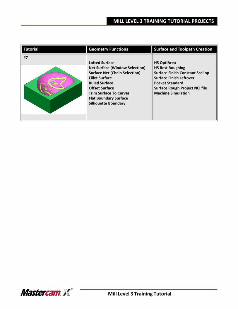
MILL LEVEL 3 TRAINING TUTORIAL PROJECTS
Tutorial Geometry Functions Surface and Toolpath Creation
#7Lofted SurfaceNet Surface (Window Selection)Surface Net (Chain Selection)Fillet SurfaceRuled SurfaceOffset SurfaceTrim Surface To Curves Flat Boundary SurfaceSilhouette Boundary
HS OptiAreaHS Rest RoughingSurface Finish Constant ScallopSurface Finish LeftoverPocket StandardSurface Rough Project NCI fileMachine Simulation
Mill Level 3 Training Tutorial
Mill Level 3 Training Tutorial Page|15
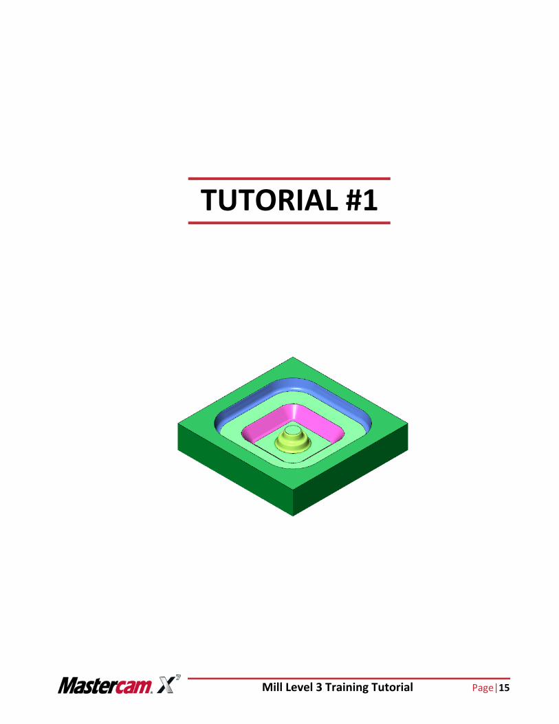
TUTORIAL #1
Page |16 Mill Level 3 Training Tutorial
TUTORIAL #11 OVERVIEW OF STEPS TAKEN TO CREATE THE FINAL PART:
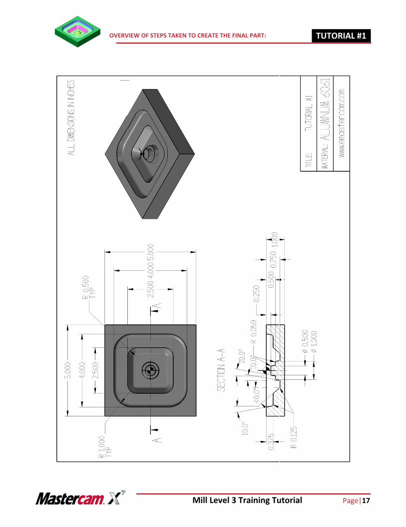
OVERVIEW OF STEPS TAKEN TO CREATE THE FINAL PART:
From Drawing to CAD Model: The student should examine the drawing on the following page to understand what part is being created in the
tutorial. From the drawing we can decide how to go about creating the geometry in Mastercam.
Create the 3D CAD Model used to generate Toolpaths from: The student will create the wireframe needed to create the surfaces. Surface creation commands such as draft surface, curve one edge, flat boundary and fillet surfaces will be used.
Create the necessary Toolpaths to machine the part: The student will set up the stock size to be used and the clamping method used. A Surface rough pocket toolpath will be created to rough out the part. A Surface finish shallow toolpath will be created to machine the floors. A Surface finish contour toolpath will be created to machine the boss walls.
Backplot and Verify the file: The Backplot will be used to simulate a step by step process of the tool’s movements. The Verify will be used to watch a tool machine the part out of a solid model.
Post Process the file to generate the G-code: The Student will then post process the file to obtain an NC file containing the necessary code for the machine.
This tutorial takes approximately two hours to complete.
Mill Level 3 Training Tutorial Page|17
OVERVIEW OF STEPS TAKEN TO CREATE THE FINAL PART: TUTORIAL #11
Page |18 Mill Level 3 Training Tutorial
TUTORIAL #11 SETTING UP THE GRAPHIC USER INTERFACE
GEOMETRY CREATION
STEP 1: SETTING UP THE GRAPHIC USER INTERFACE
Please refer to the Getting Started section to set up the graphics user interface.
STEP 2: CREATE RECTANGLES
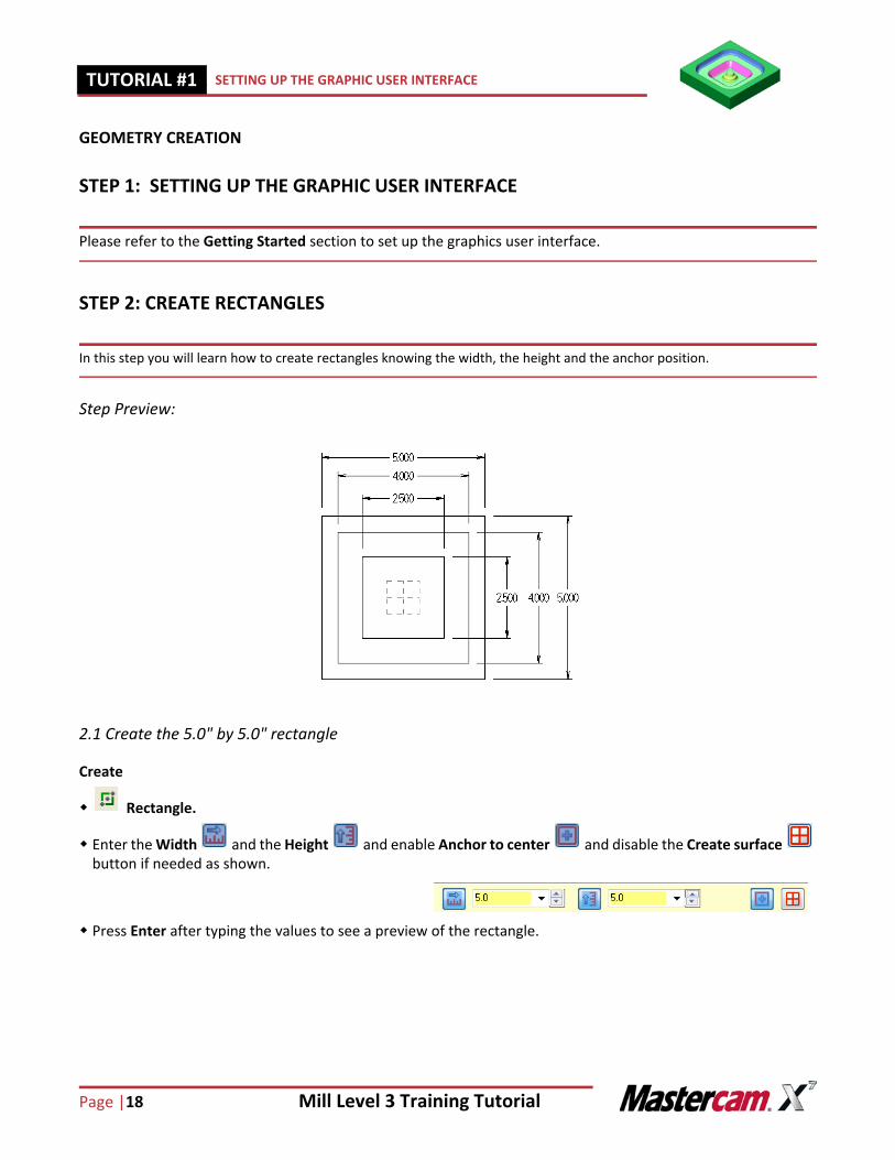
In this step you will learn how to create rectangles knowing the width, the height and the anchor position.
Step Preview:
2.1 Create the 5.0" by 5.0" rectangle
Create
Rectangle.
Enter the Width and the Height and enable Anchor to center and disable the Create surface button if needed as shown.
Press Enter after typing the values to see a preview of the rectangle.
Mill Level 3 Training Tutorial Page|19
CREATE RECTANGLES TUTORIAL #11
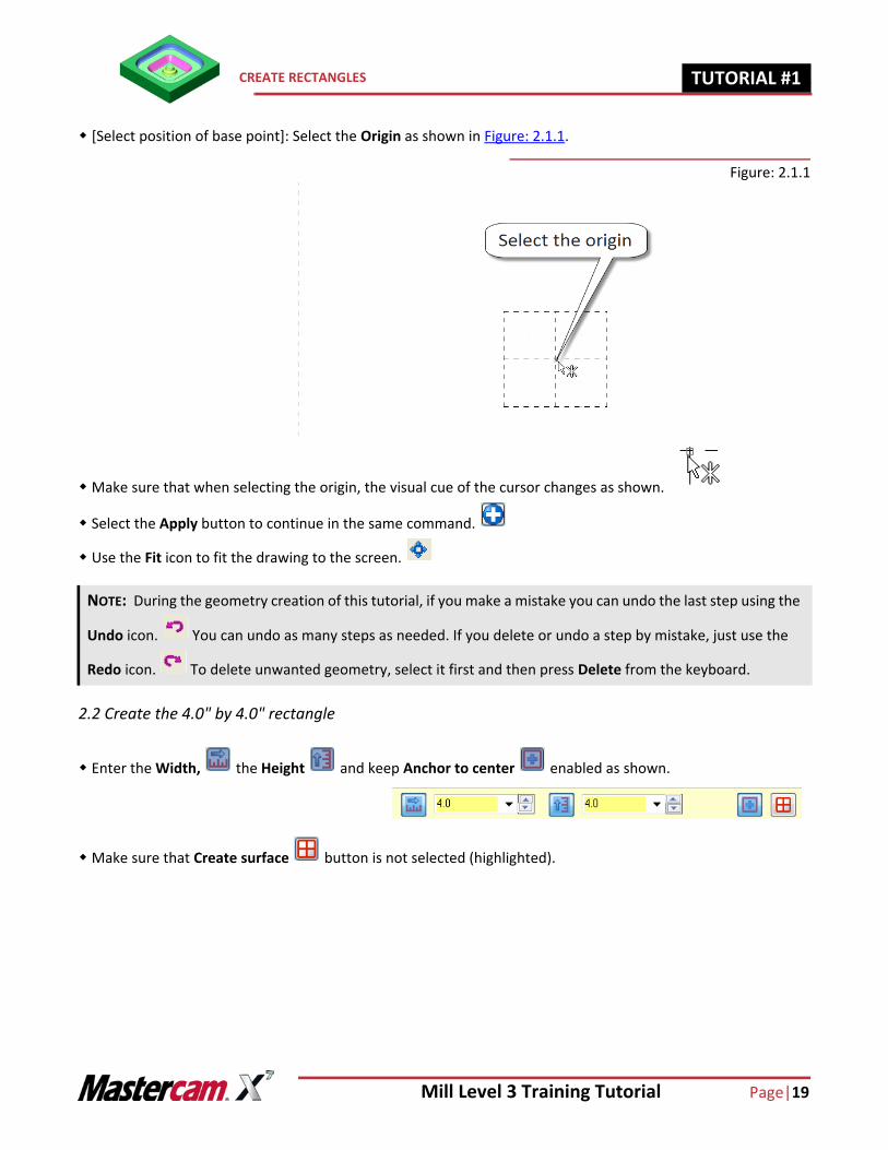
[Select position of base point]: Select the Origin as shown in Figure: 2.1.1.
Figure: 2.1.1
Make sure that when selecting the origin, the visual cue of the cursor changes as shown.
Select the Apply button to continue in the same command.
Use the Fit icon to fit the drawing to the screen.
2.2 Create the 4.0" by 4.0" rectangle
Enter the Width, the Height and keep Anchor to center enabled as shown.
Make sure that Create surface button is not selected (highlighted).
NOTE: During the geometry creation of this tutorial, if you make a mistake you can undo the last step using the
Undo icon. You can undo as many steps as needed. If you delete or undo a step by mistake, just use the
Redo icon. To delete unwanted geometry, select it first and then press Delete from the keyboard.
Page |20 Mill Level 3 Training Tutorial
TUTORIAL #11 CREATE RECTANGLES
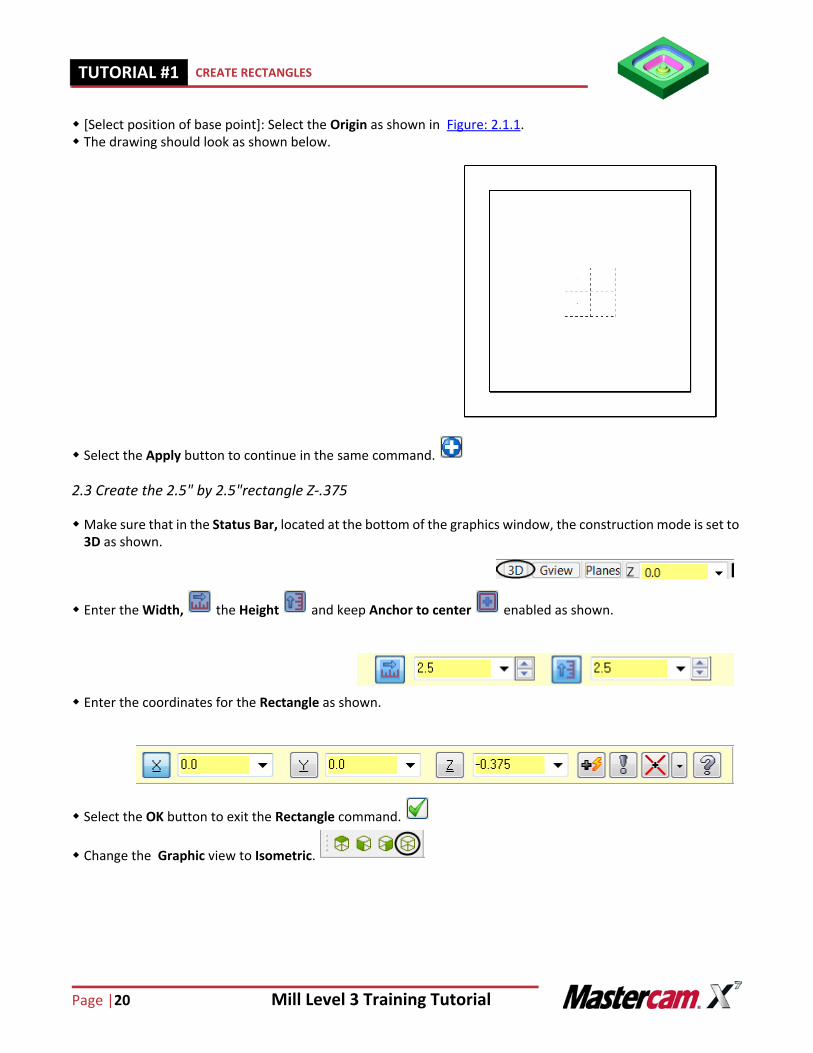
[Select position of base point]: Select the Origin as shown in Figure: 2.1.1. The drawing should look as shown below.
Select the Apply button to continue in the same command.
2.3 Create the 2.5" by 2.5"rectangle Z-.375
Make sure that in the Status Bar, located at the bottom of the graphics window, the construction mode is set to 3D as shown.
Enter the Width, the Height and keep Anchor to center enabled as shown.
Enter the coordinates for the Rectangle as shown.
Select the OK button to exit the Rectangle command.
Change the Graphic view to Isometric.
Mill Level 3 Training Tutorial Page|21
CREATE FILLETS FOR THE TWO RECTANGLES TUTORIAL #11
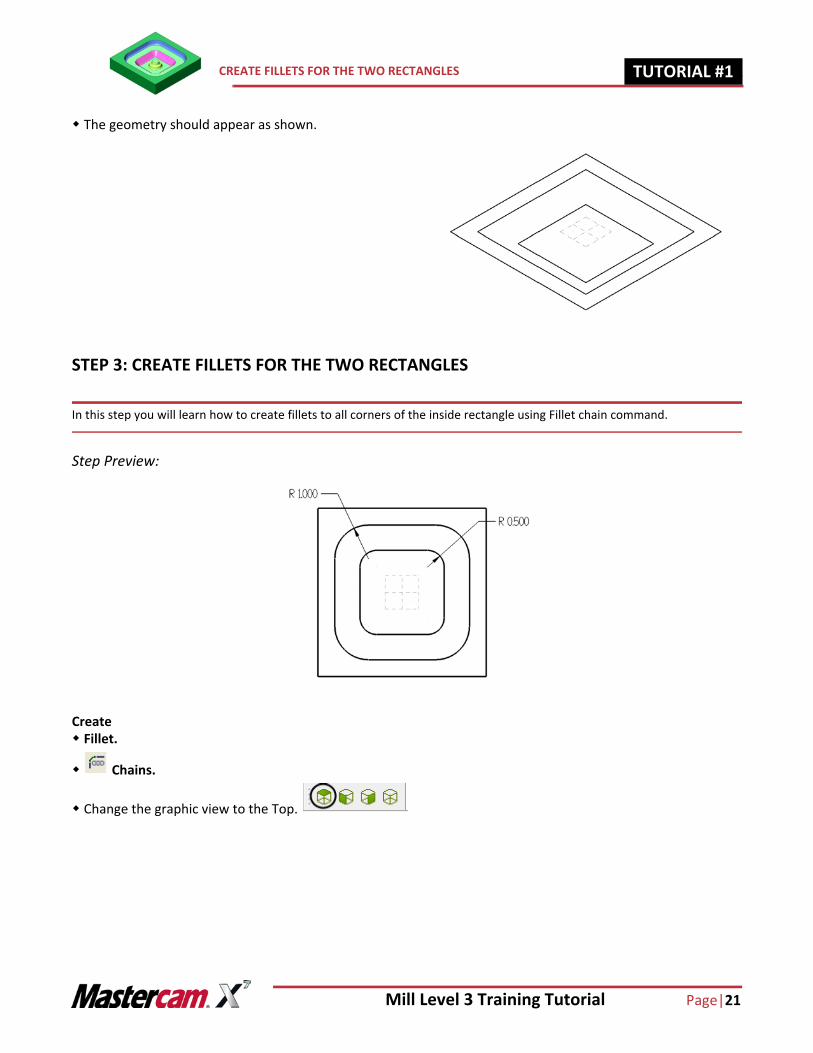
The geometry should appear as shown.
STEP 3: CREATE FILLETS FOR THE TWO RECTANGLES
In this step you will learn how to create fillets to all corners of the inside rectangle using Fillet chain command.
Step Preview:
Create Fillet.
Chains.
Change the graphic view to the Top.
Page |22 Mill Level 3 Training Tutorial
TUTORIAL #11 CREATE FILLETS FOR THE TWO RECTANGLES
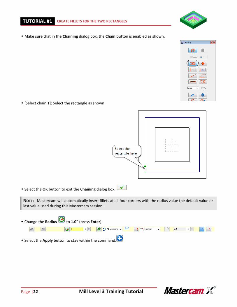
Make sure that in the Chaining dialog box, the Chain button is enabled as shown.
[Select chain 1]: Select the rectangle as shown.
Select the OK button to exit the Chaining dialog box.
Change the Radius to 1.0" (press Enter).
Select the Apply button to stay within the command.
NOTE: Mastercam will automatically insert fillets at all four corners with the radius value the default value or last value used during this Mastercam session.
Mill Level 3 Training Tutorial Page|23
CREATE FILLETS FOR THE TWO RECTANGLES TUTORIAL #11
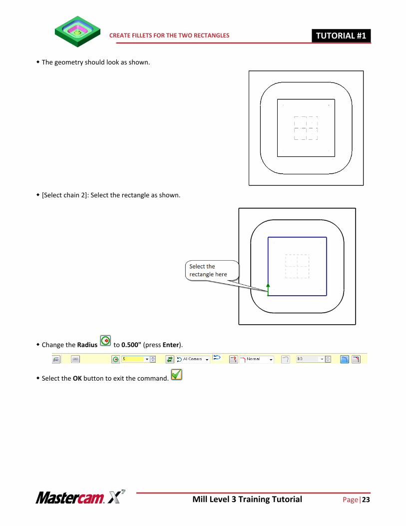
The geometry should look as shown.
[Select chain 2]: Select the rectangle as shown.
Change the Radius to 0.500" (press Enter).
Select the OK button to exit the command.
Page |24 Mill Level 3 Training Tutorial
TUTORIAL #11 CREATE CIRCLE CENTER POINT
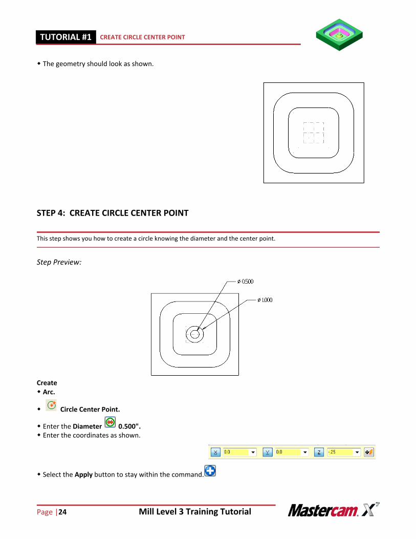
The geometry should look as shown.
STEP 4: CREATE CIRCLE CENTER POINT
This step shows you how to create a circle knowing the diameter and the center point.
Step Preview:
Create Arc.
Circle Center Point.
Enter the Diameter 0.500". Enter the coordinates as shown.
Select the Apply button to stay within the command.
Mill Level 3 Training Tutorial Page|25
CREATE CIRCLE CENTER POINT TUTORIAL #11
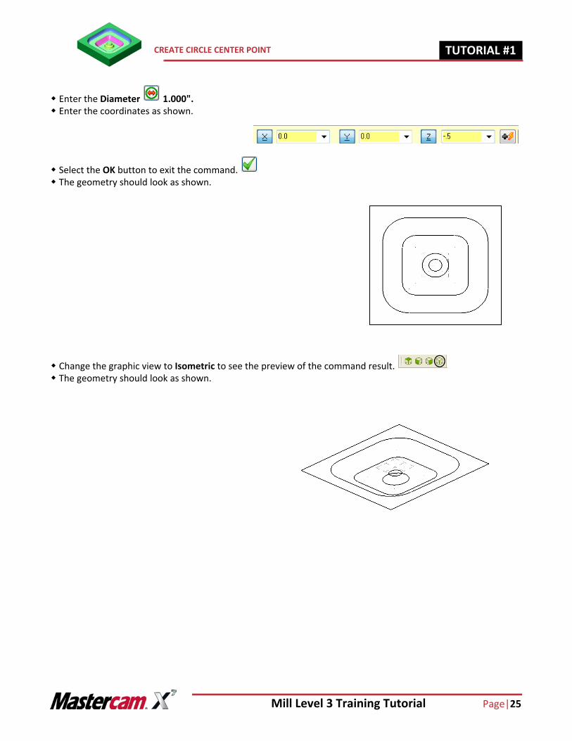
Enter the Diameter 1.000". Enter the coordinates as shown.
Select the OK button to exit the command. The geometry should look as shown.
Change the graphic view to Isometric to see the preview of the command result. The geometry should look as shown.
Page |26 Mill Level 3 Training Tutorial
TUTORIAL #11 CREATE THE DRAFT SURFACES
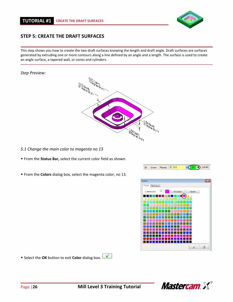
STEP 5: CREATE THE DRAFT SURFACES
This step shows you how to create the two draft surfaces knowing the length and draft angle. Draft surfaces are surfaces generated by extruding one or more contours along a line defined by an angle and a length. The surface is used to create an angle surface, a tapered wall, or cones and cylinders.
Step Preview:
5.1 Change the main color to magenta no 13
From the Status Bar, select the current color field as shown.
From the Colors dialog box, select the magenta color, no 13.
Select the OK button to exit Color dialog box.
Mill Level 3 Training Tutorial Page|27
CREATE THE DRAFT SURFACES TUTORIAL #11
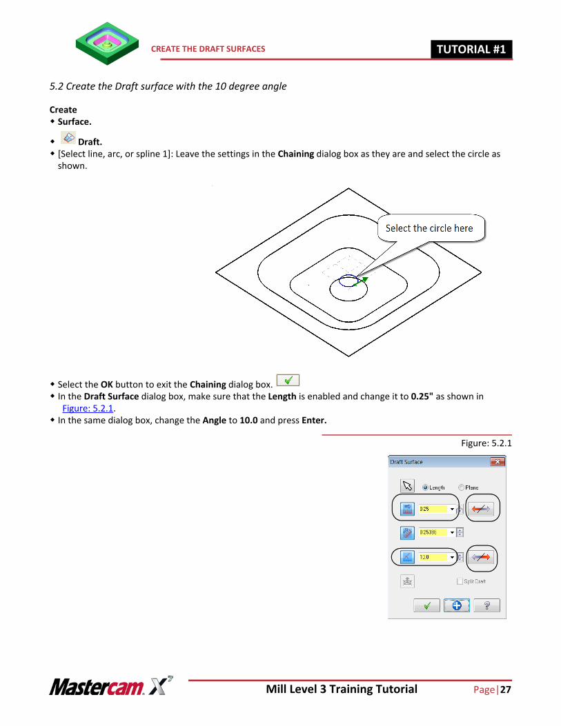
5.2 Create the Draft surface with the 10 degree angle
Create Surface.
Draft. [Select line, arc, or spline 1]: Leave the settings in the Chaining dialog box as they are and select the circle as
shown.
Select the OK button to exit the Chaining dialog box. In the Draft Surface dialog box, make sure that the Length is enabled and change it to 0.25" as shown in
Figure: 5.2.1. In the same dialog box, change the Angle to 10.0 and press Enter.
Figure: 5.2.1
Page |28 Mill Level 3 Training Tutorial
TUTORIAL #11 CREATE THE DRAFT SURFACES
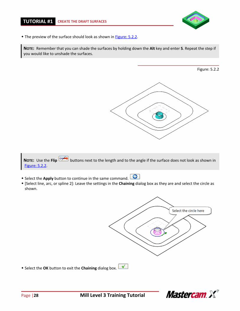
The preview of the surface should look as shown in Figure: 5.2.2.
Figure: 5.2.2
Select the Apply button to continue in the same command. [Select line, arc, or spline 2]: Leave the settings in the Chaining dialog box as they are and select the circle as
shown.
Select the OK button to exit the Chaining dialog box.
NOTE: Remember that you can shade the surfaces by holding down the Alt key and enter S. Repeat the step if you would like to unshade the surfaces.
NOTE: Use the Flip buttons next to the length and to the angle if the surface does not look as shown in Figure: 5.2.2.
Mill Level 3 Training Tutorial Page|29
CREATE THE DRAFT SURFACES TUTORIAL #11
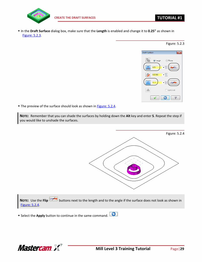
In the Draft Surface dialog box, make sure that the Length is enabled and change it to 0.25" as shown in Figure: 5.2.3.
Figure: 5.2.3
The preview of the surface should look as shown in Figure: 5.2.4.
Figure: 5.2.4
Select the Apply button to continue in the same command.
NOTE: Remember that you can shade the surfaces by holding down the Alt key and enter S. Repeat the step if you would like to unshade the surfaces.
NOTE: Use the Flip buttons next to the length and to the angle if the surface does not look as shown in Figure: 5.2.4.
Page |30 Mill Level 3 Training Tutorial
TUTORIAL #11 CREATE THE DRAFT SURFACES
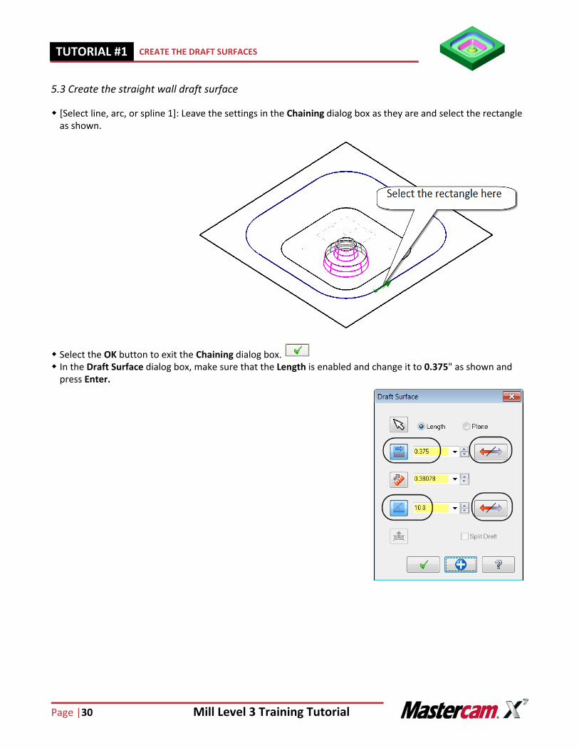
5.3 Create the straight wall draft surface
[Select line, arc, or spline 1]: Leave the settings in the Chaining dialog box as they are and select the rectangle as shown.
Select the OK button to exit the Chaining dialog box. In the Draft Surface dialog box, make sure that the Length is enabled and change it to 0.375" as shown and
press Enter.
Mill Level 3 Training Tutorial Page|31
CREATE THE DRAFT SURFACES TUTORIAL #11
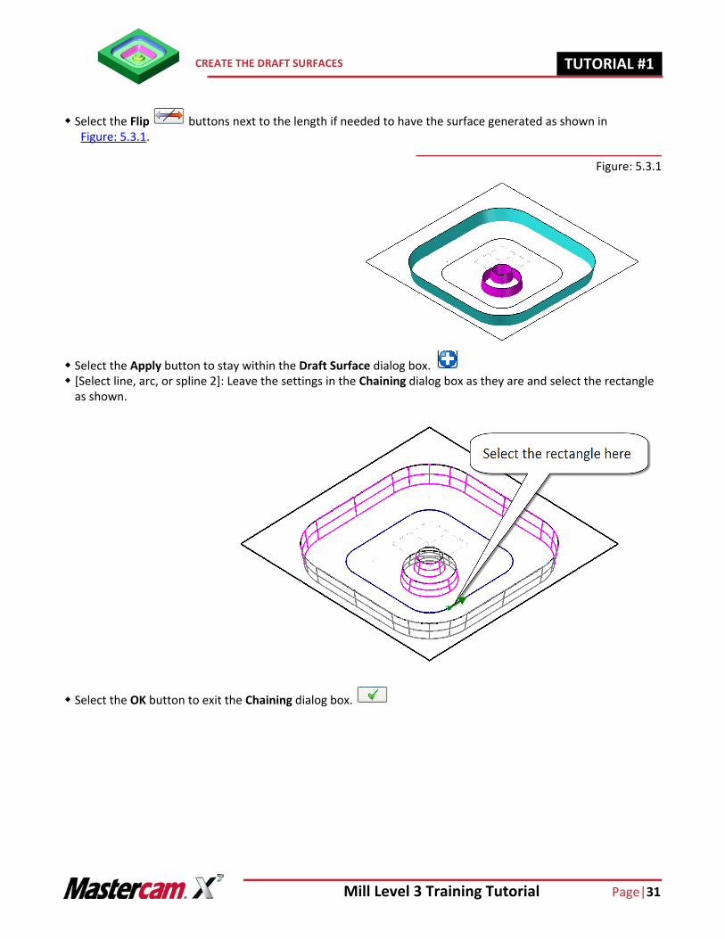
Select the Flip buttons next to the length if needed to have the surface generated as shown in Figure: 5.3.1.
Figure: 5.3.1
Select the Apply button to stay within the Draft Surface dialog box. [Select line, arc, or spline 2]: Leave the settings in the Chaining dialog box as they are and select the rectangle
as shown.
Select the OK button to exit the Chaining dialog box.
Page |32 Mill Level 3 Training Tutorial
TUTORIAL #11 CREATE THE DRAFT SURFACES
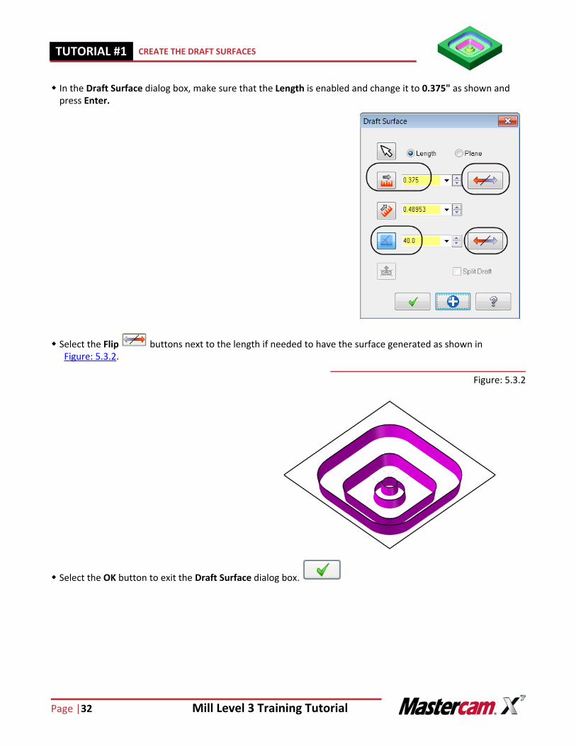
In the Draft Surface dialog box, make sure that the Length is enabled and change it to 0.375" as shown and press Enter.
Select the Flip buttons next to the length if needed to have the surface generated as shown in Figure: 5.3.2.
Figure: 5.3.2
Select the OK button to exit the Draft Surface dialog box.
Mill Level 3 Training Tutorial Page|33
CREATE A CURVE AT THE EDGE OF THE SURFACE TUTORIAL #11
STEP 6: CREATE A CURVE AT THE EDGE OF THE SURFACE
In this step you will learn how to create a curve at the open edge of the boss draft surface. Create curve one edge command allows you to create a curve on a single surface edge.
Step Preview:
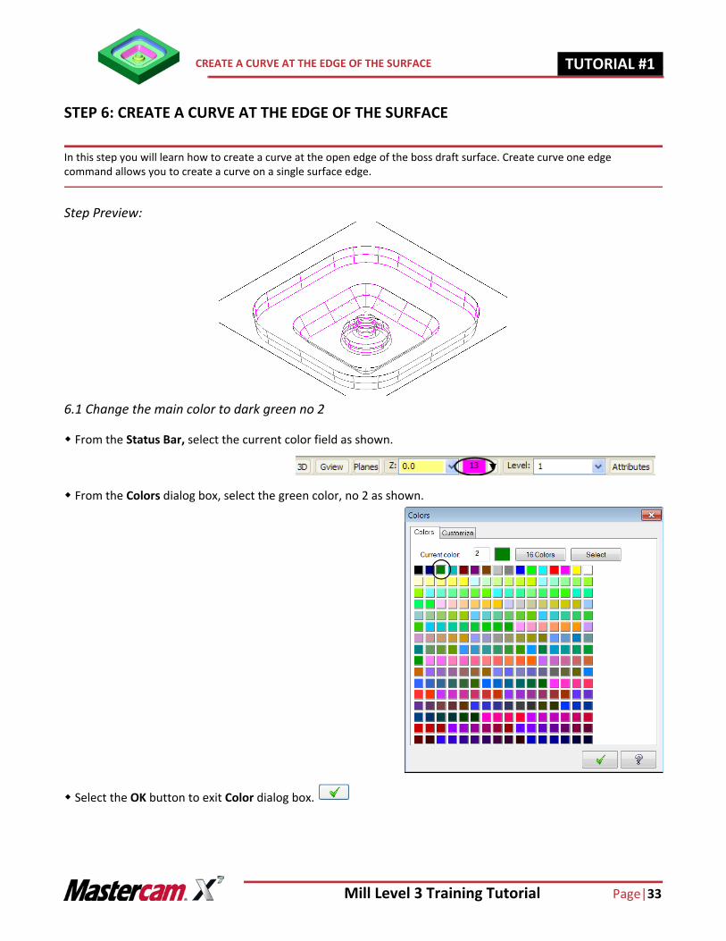
6.1 Change the main color to dark green no 2
From the Status Bar, select the current color field as shown.
From the Colors dialog box, select the green color, no 2 as shown.
Select the OK button to exit Color dialog box.
Page |34 Mill Level 3 Training Tutorial
TUTORIAL #11 CREATE A CURVE AT THE EDGE OF THE SURFACE
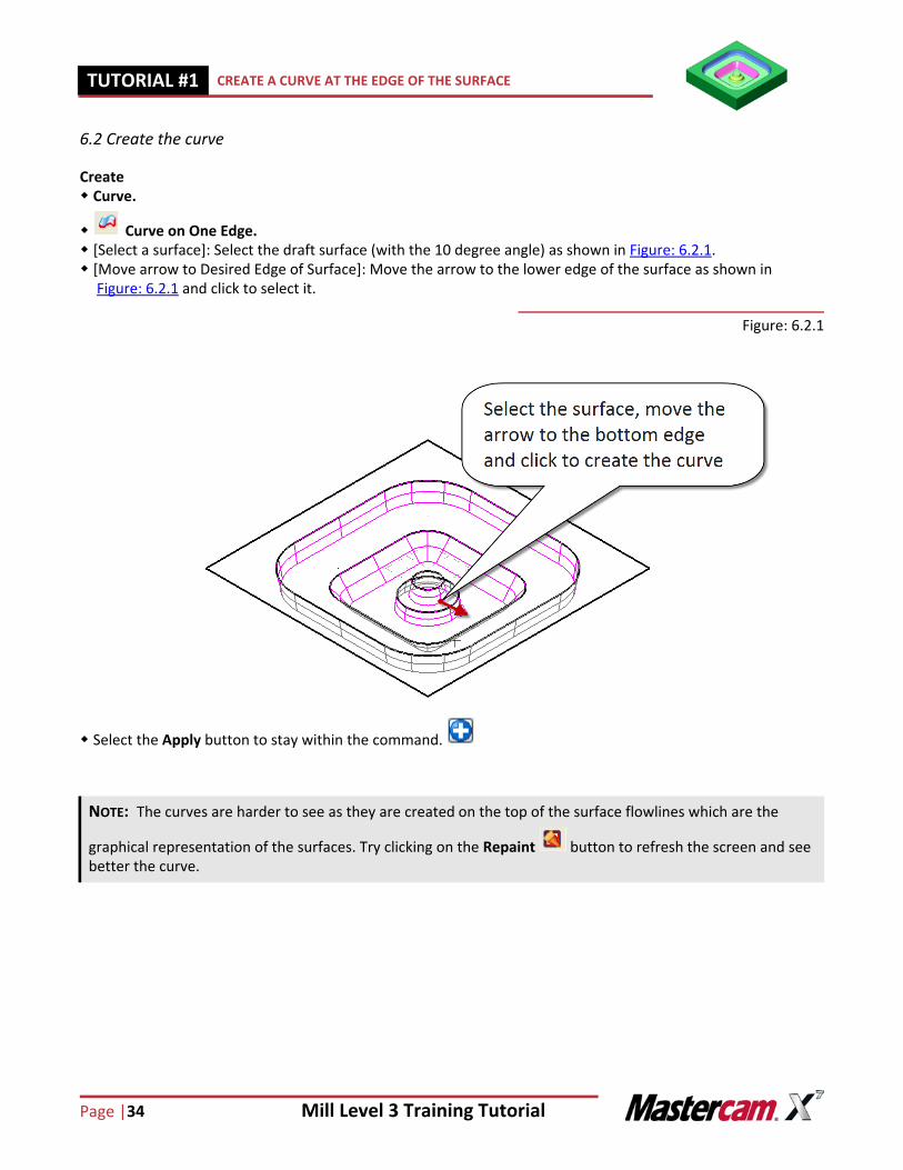
6.2 Create the curve
Create Curve.
Curve on One Edge. [Select a surface]: Select the draft surface (with the 10 degree angle) as shown in Figure: 6.2.1. [Move arrow to Desired Edge of Surface]: Move the arrow to the lower edge of the surface as shown in
Figure: 6.2.1 and click to select it.
Figure: 6.2.1
Select the Apply button to stay within the command.
NOTE: The curves are harder to see as they are created on the top of the surface flowlines which are the
graphical representation of the surfaces. Try clicking on the Repaint button to refresh the screen and see better the curve.
Mill Level 3 Training Tutorial Page|35
CREATE A CURVE AT THE EDGE OF THE SURFACE TUTORIAL #11
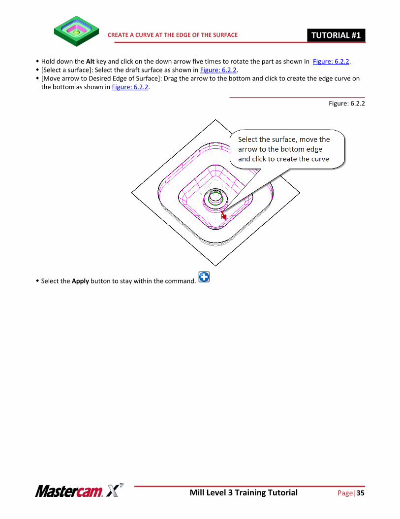
Hold down the Alt key and click on the down arrow five times to rotate the part as shown in Figure: 6.2.2. [Select a surface]: Select the draft surface as shown in Figure: 6.2.2. [Move arrow to Desired Edge of Surface]: Drag the arrow to the bottom and click to create the edge curve on
the bottom as shown in Figure: 6.2.2.
Figure: 6.2.2
Select the Apply button to stay within the command.
Page |36 Mill Level 3 Training Tutorial
TUTORIAL #11 CREATE A CURVE AT THE EDGE OF THE SURFACE
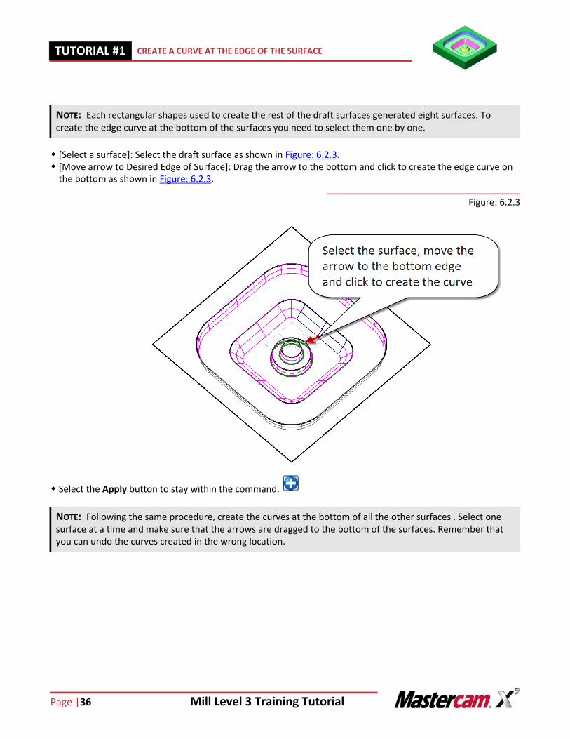
[Select a surface]: Select the draft surface as shown in Figure: 6.2.3. [Move arrow to Desired Edge of Surface]: Drag the arrow to the bottom and click to create the edge curve on
the bottom as shown in Figure: 6.2.3.
Figure: 6.2.3
Select the Apply button to stay within the command.
NOTE: Each rectangular shapes used to create the rest of the draft surfaces generated eight surfaces. To create the edge curve at the bottom of the surfaces you need to select them one by one.
NOTE: Following the same procedure, create the curves at the bottom of all the other surfaces . Select one surface at a time and make sure that the arrows are dragged to the bottom of the surfaces. Remember that you can undo the curves created in the wrong location.
Mill Level 3 Training Tutorial Page|37
CREATE A FLAT BOUNDARY SURFACE TUTORIAL #11
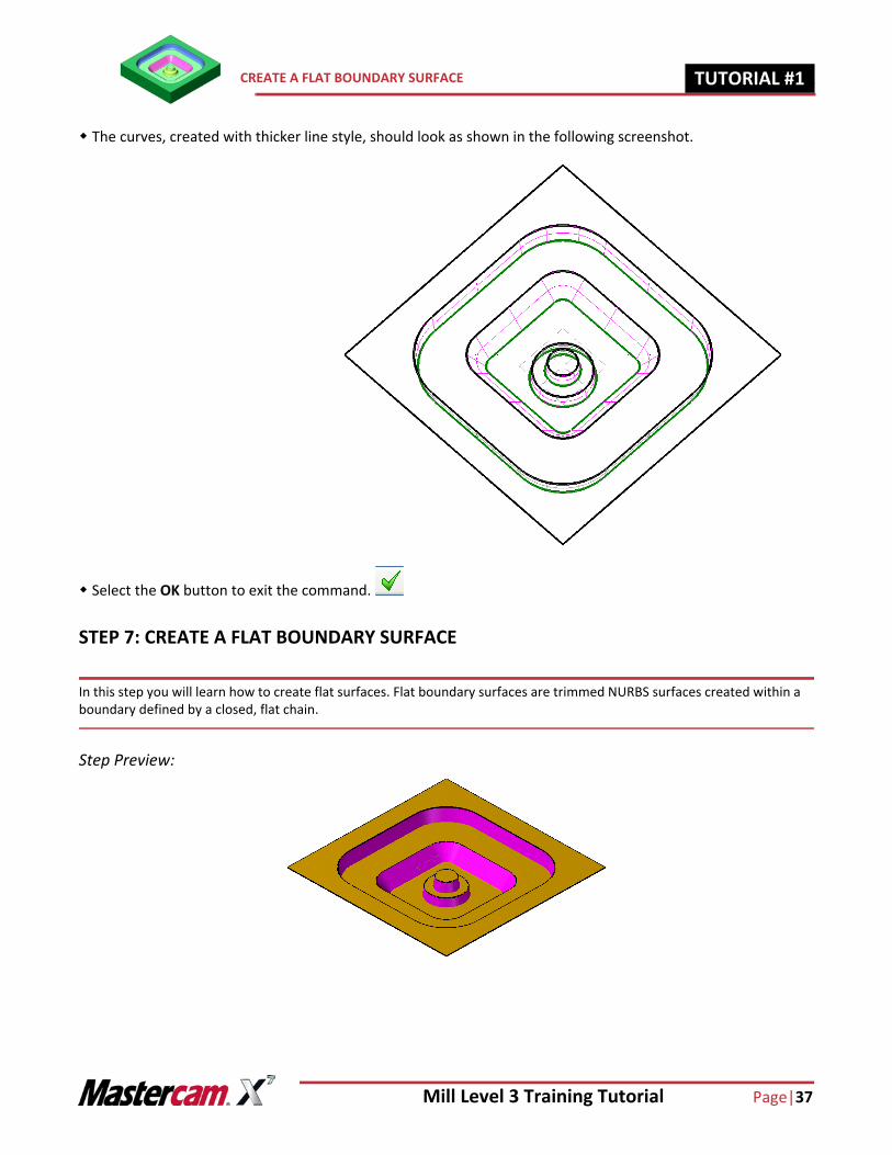
The curves, created with thicker line style, should look as shown in the following screenshot.
Select the OK button to exit the command.
STEP 7: CREATE A FLAT BOUNDARY SURFACE
In this step you will learn how to create flat surfaces. Flat boundary surfaces are trimmed NURBS surfaces created within a boundary defined by a closed, flat chain.
Step Preview:
Page |38 Mill Level 3 Training Tutorial
TUTORIAL #11 CREATE A FLAT BOUNDARY SURFACE
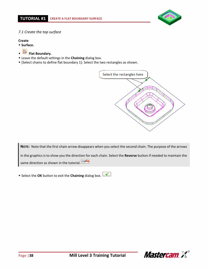
7.1 Create the top surface
Create Surface.
Flat Boundary. Leave the default settings in the Chaining dialog box. [Select chains to define flat boundary 1]: Select the two rectangles as shown.
Select the OK button to exit the Chaining dialog box.
NOTE: Note that the first chain arrow disappears when you select the second chain. The purpose of the arrows
in the graphics is to show you the direction for each chain. Select the Reverse button if needed to maintain the
same direction as shown in the tutorial.
Mill Level 3 Training Tutorial Page|39
CREATE A FLAT BOUNDARY SURFACE TUTORIAL #11
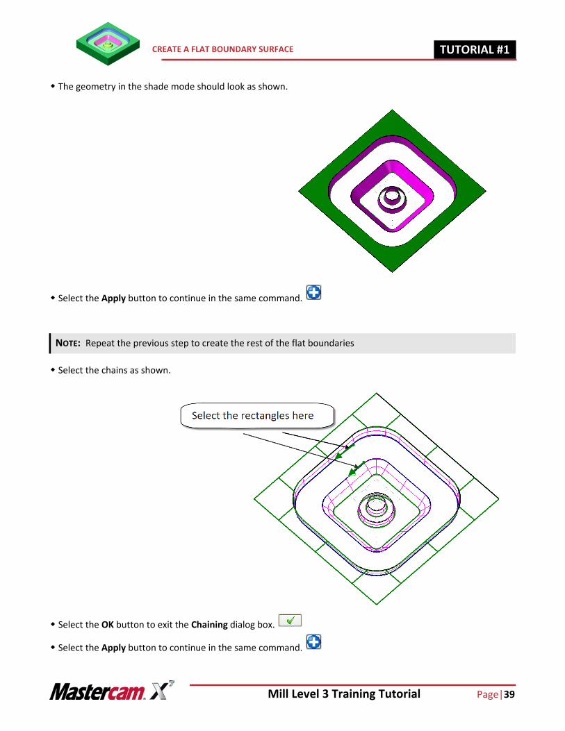
The geometry in the shade mode should look as shown.
Select the Apply button to continue in the same command.
Select the chains as shown.
Select the OK button to exit the Chaining dialog box.
Select the Apply button to continue in the same command.
NOTE: Repeat the previous step to create the rest of the flat boundaries
Page |40 Mill Level 3 Training Tutorial
TUTORIAL #11 CREATE A FLAT BOUNDARY SURFACE
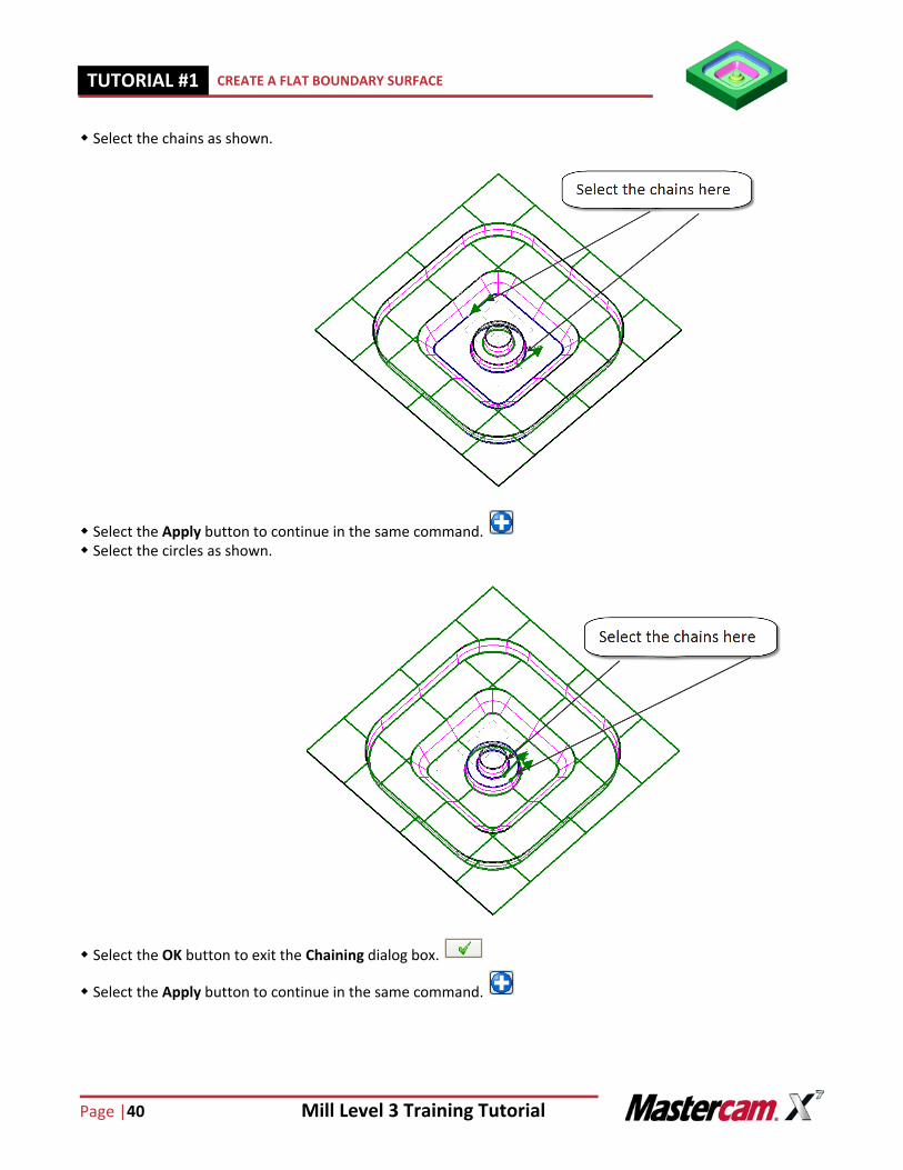
Select the chains as shown.
Select the Apply button to continue in the same command. Select the circles as shown.
Select the OK button to exit the Chaining dialog box.
Select the Apply button to continue in the same command.
Mill Level 3 Training Tutorial Page|41
CREATE A FLAT BOUNDARY SURFACE TUTORIAL #11
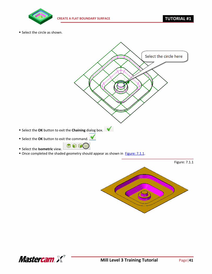
Select the circle as shown.
Select the OK button to exit the Chaining dialog box.
Select the OK button to exit the command.
Select the Isometric view. Once completed the shaded geometry should appear as shown in Figure: 7.1.1.
Figure: 7.1.1
Page |42 Mill Level 3 Training Tutorial
TUTORIAL #11 CREATE A FLAT BOUNDARY SURFACE
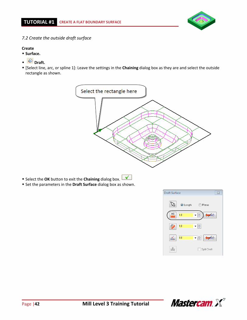
7.2 Create the outside draft surface
Create Surface.
Draft. [Select line, arc, or spline 1]: Leave the settings in the Chaining dialog box as they are and select the outside
rectangle as shown.
Select the OK button to exit the Chaining dialog box. Set the parameters in the Draft Surface dialog box as shown.
Mill Level 3 Training Tutorial Page|43
CREATE A FLAT BOUNDARY SURFACE TUTORIAL #11
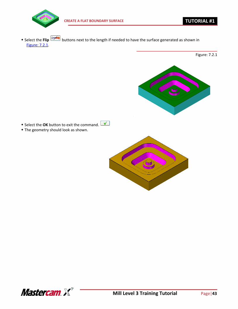
Select the Flip buttons next to the length if needed to have the surface generated as shown in Figure: 7.2.1.
Figure: 7.2.1
Select the OK button to exit the command. The geometry should look as shown.
Page |44 Mill Level 3 Training Tutorial
TUTORIAL #11 CREATE THE FILLET SURFACES
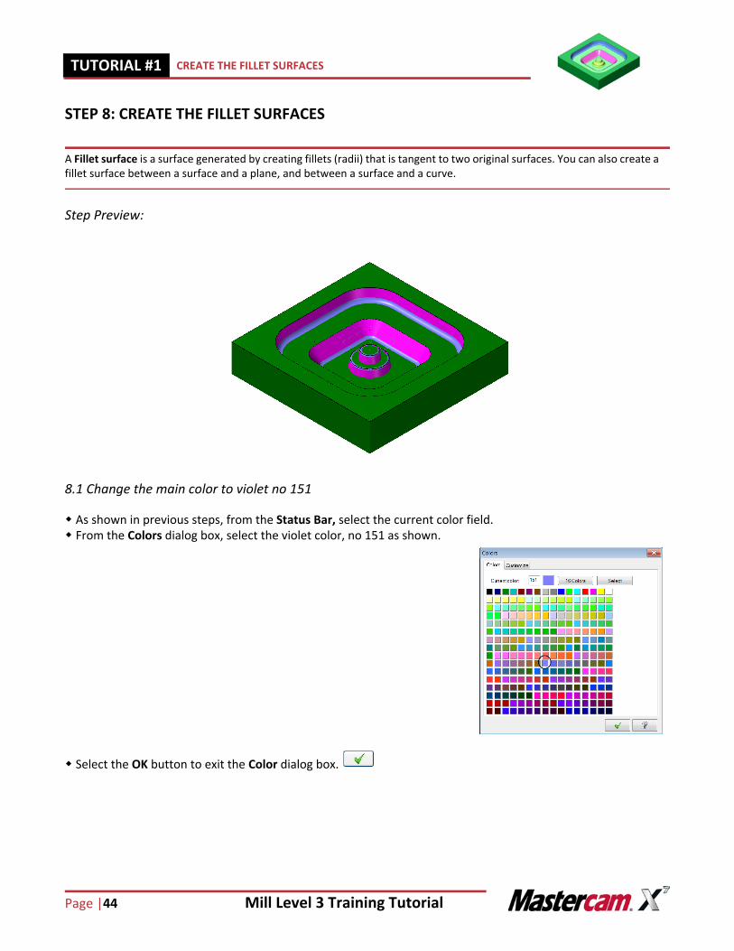
STEP 8: CREATE THE FILLET SURFACES
A Fillet surface is a surface generated by creating fillets (radii) that is tangent to two original surfaces. You can also create a fillet surface between a surface and a plane, and between a surface and a curve.
Step Preview:
8.1 Change the main color to violet no 151
As shown in previous steps, from the Status Bar, select the current color field. From the Colors dialog box, select the violet color, no 151 as shown.
Select the OK button to exit the Color dialog box.
Mill Level 3 Training Tutorial Page|45
CREATE THE FILLET SURFACES TUTORIAL #11
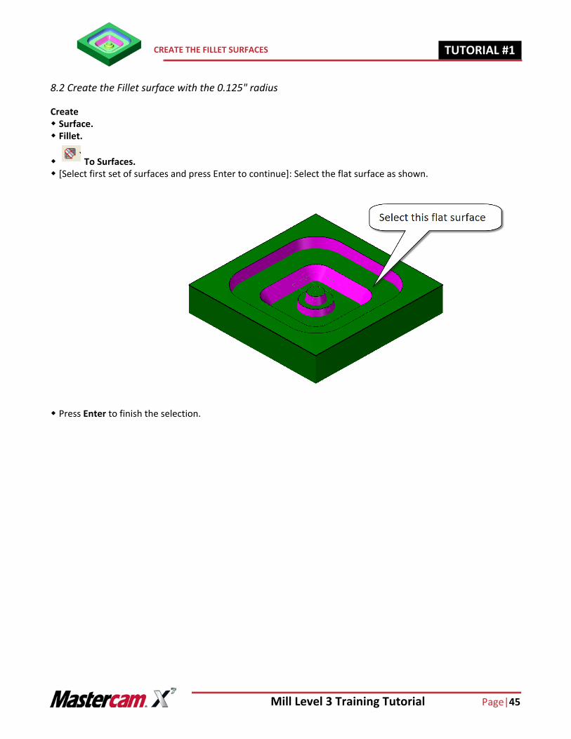
8.2 Create the Fillet surface with the 0.125" radius
Create Surface. Fillet.
To Surfaces. [Select first set of surfaces and press Enter to continue]: Select the flat surface as shown.
Press Enter to finish the selection.
Page |46 Mill Level 3 Training Tutorial
TUTORIAL #11 CREATE THE FILLET SURFACES
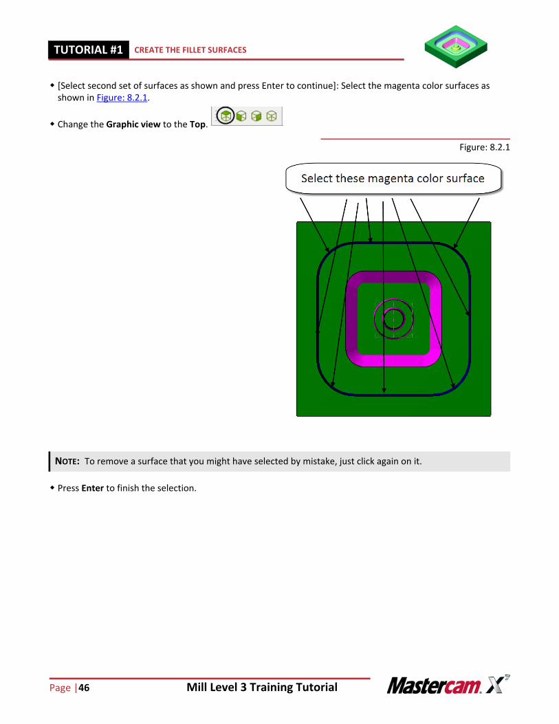
[Select second set of surfaces as shown and press Enter to continue]: Select the magenta color surfaces as shown in Figure: 8.2.1.
Change the Graphic view to the Top.
Figure: 8.2.1
Press Enter to finish the selection.
NOTE: To remove a surface that you might have selected by mistake, just click again on it.
Mill Level 3 Training Tutorial Page|47
CREATE THE FILLET SURFACES TUTORIAL #11
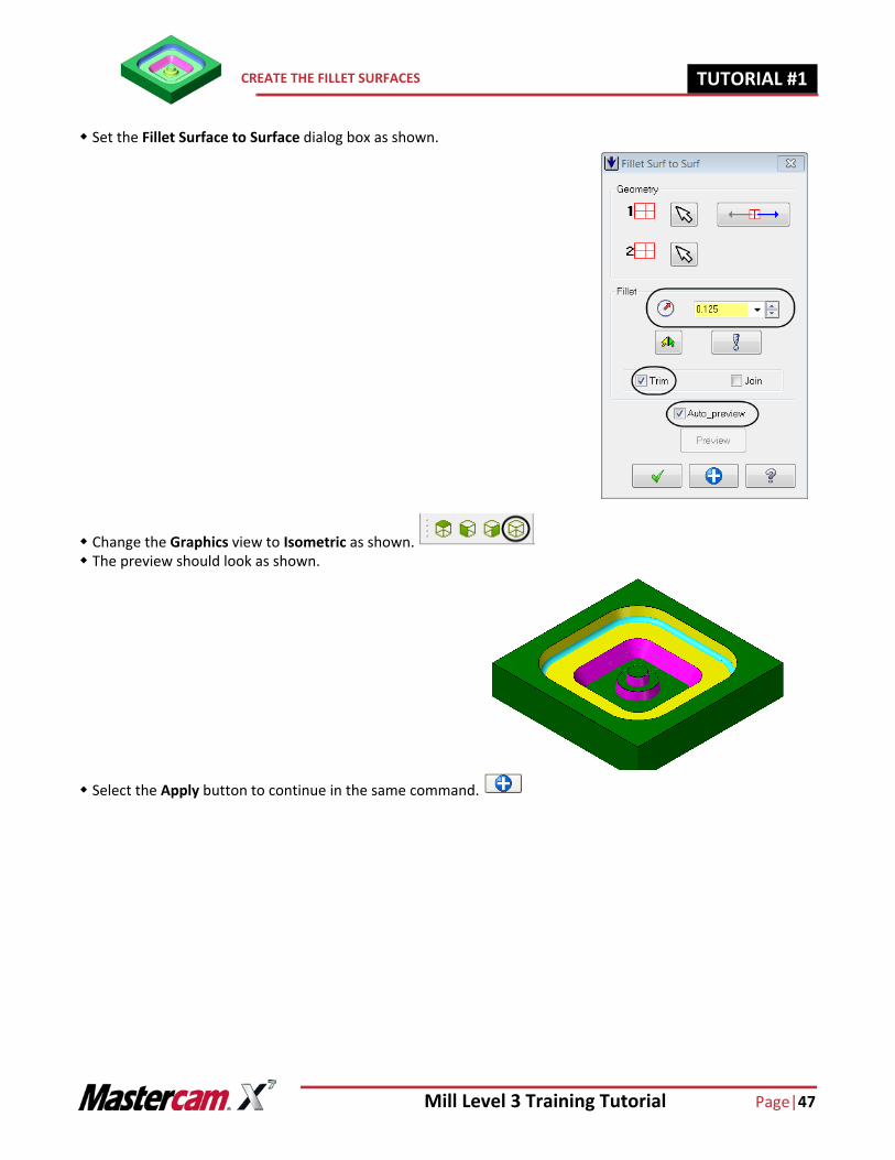
Set the Fillet Surface to Surface dialog box as shown.
Change the Graphics view to Isometric as shown. The preview should look as shown.
Select the Apply button to continue in the same command.
Page |48 Mill Level 3 Training Tutorial
TUTORIAL #11 CREATE THE FILLET SURFACES
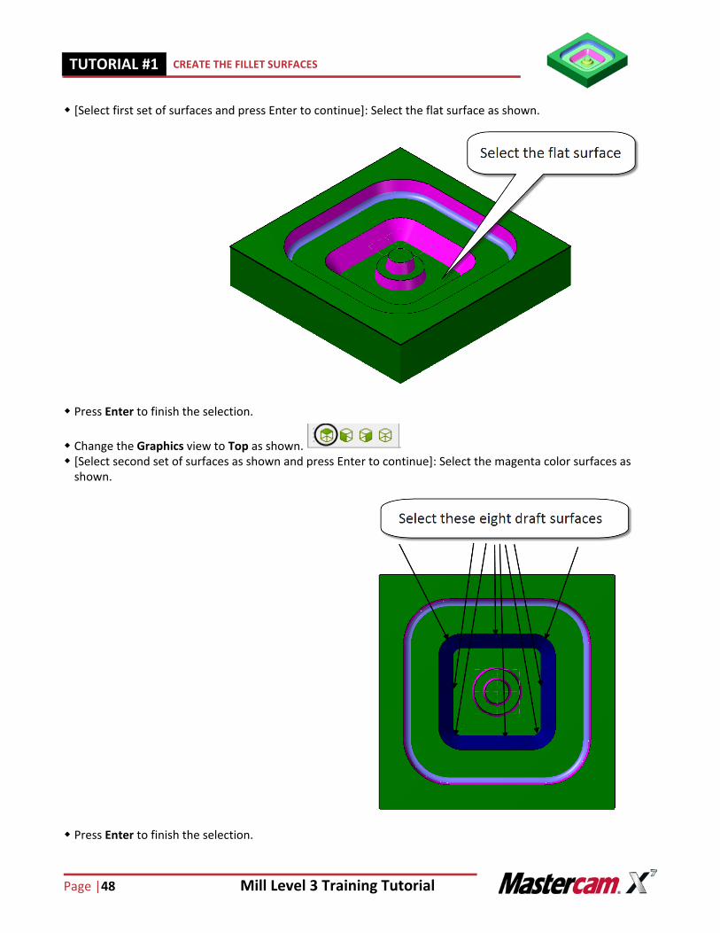
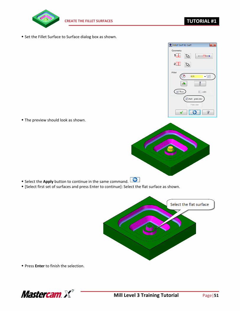
[Select first set of surfaces and press Enter to continue]: Select the flat surface as shown.
Press Enter to finish the selection.
Change the Graphics view to Top as shown. [Select second set of surfaces as shown and press Enter to continue]: Select the magenta color surfaces as
shown.
Press Enter to finish the selection.

Mill Level 3 Training Tutorial Page|49
CREATE THE FILLET SURFACES TUTORIAL #11
Set the Fillet Surface to Surface dialog box as shown.
Change the Graphics view to Isometric as shown. The preview should look as shown.
Select the Apply button to continue in the same command.
Page |50 Mill Level 3 Training Tutorial
TUTORIAL #11 CREATE THE FILLET SURFACES
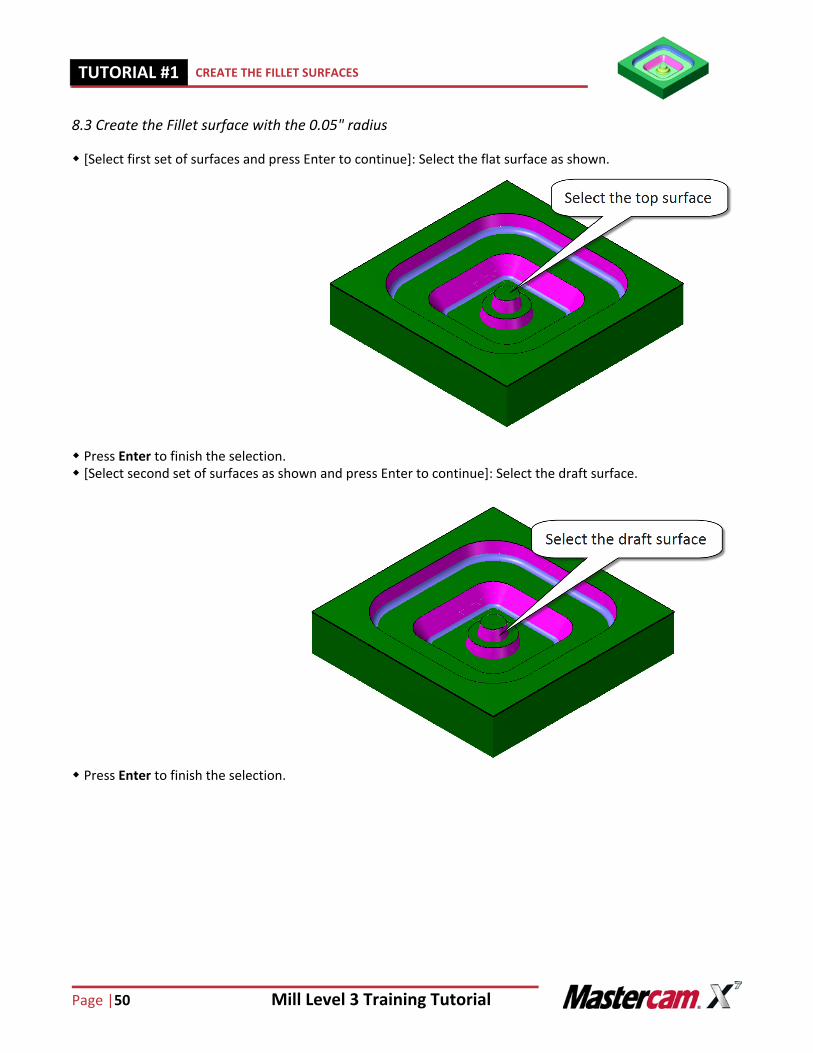
8.3 Create the Fillet surface with the 0.05" radius
[Select first set of surfaces and press Enter to continue]: Select the flat surface as shown.
Press Enter to finish the selection. [Select second set of surfaces as shown and press Enter to continue]: Select the draft surface.
Press Enter to finish the selection.
Mill Level 3 Training Tutorial Page|51
CREATE THE FILLET SURFACES TUTORIAL #11
Set the Fillet Surface to Surface dialog box as shown.
The preview should look as shown.
Select the Apply button to continue in the same command. [Select first set of surfaces and press Enter to continue]: Select the flat surface as shown.
Press Enter to finish the selection.
Page |52 Mill Level 3 Training Tutorial
TUTORIAL #11 CREATE THE FILLET SURFACES
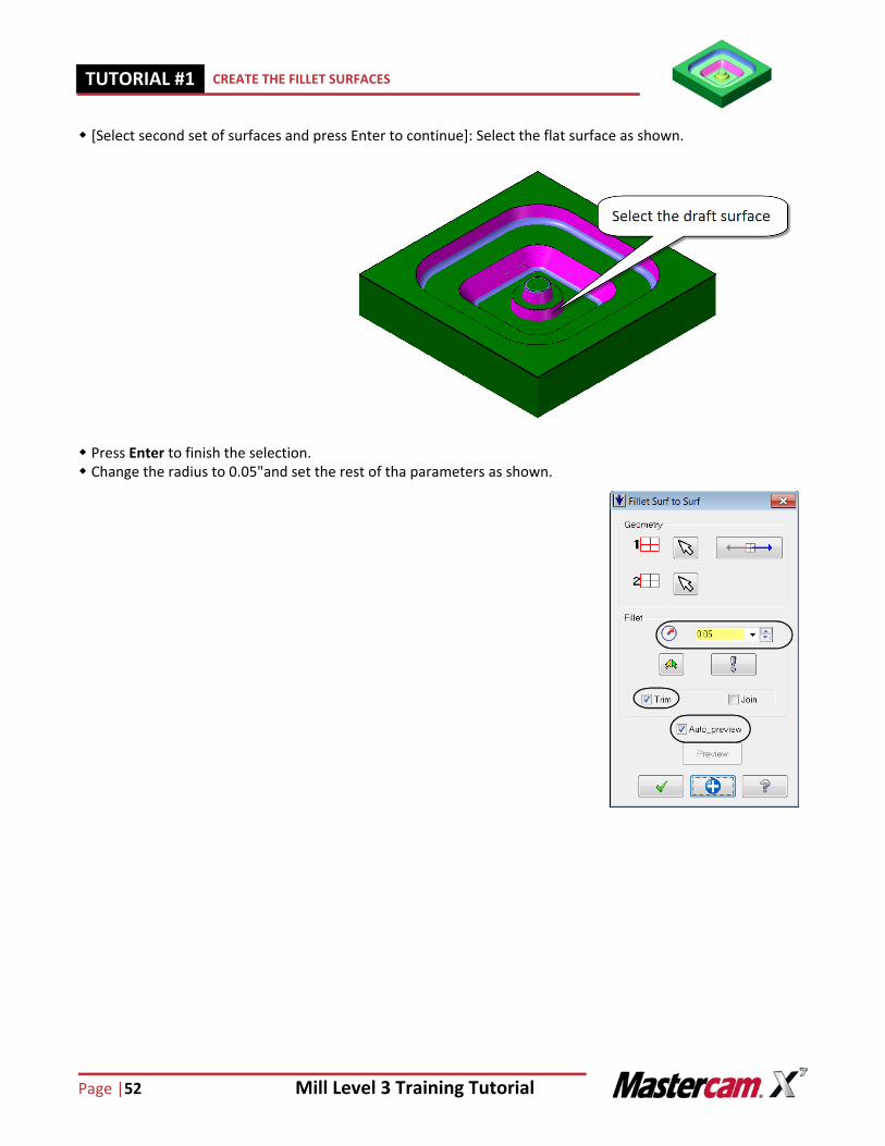
[Select second set of surfaces and press Enter to continue]: Select the flat surface as shown.
Press Enter to finish the selection. Change the radius to 0.05"and set the rest of tha parameters as shown.
Mill Level 3 Training Tutorial Page|53
SAVE THE FILE TUTORIAL #11
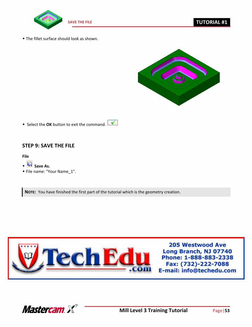
The fillet surface should look as shown.
Select the OK button to exit the command.
STEP 9: SAVE THE FILE
File
Save As. File name: "Your Name_1".
NOTE: You have finished the first part of the tutorial which is the geometry creation.
Page |54 Mill Level 3 Training Tutorial
TUTORIAL #11 SUGGESTED FIXTURE:
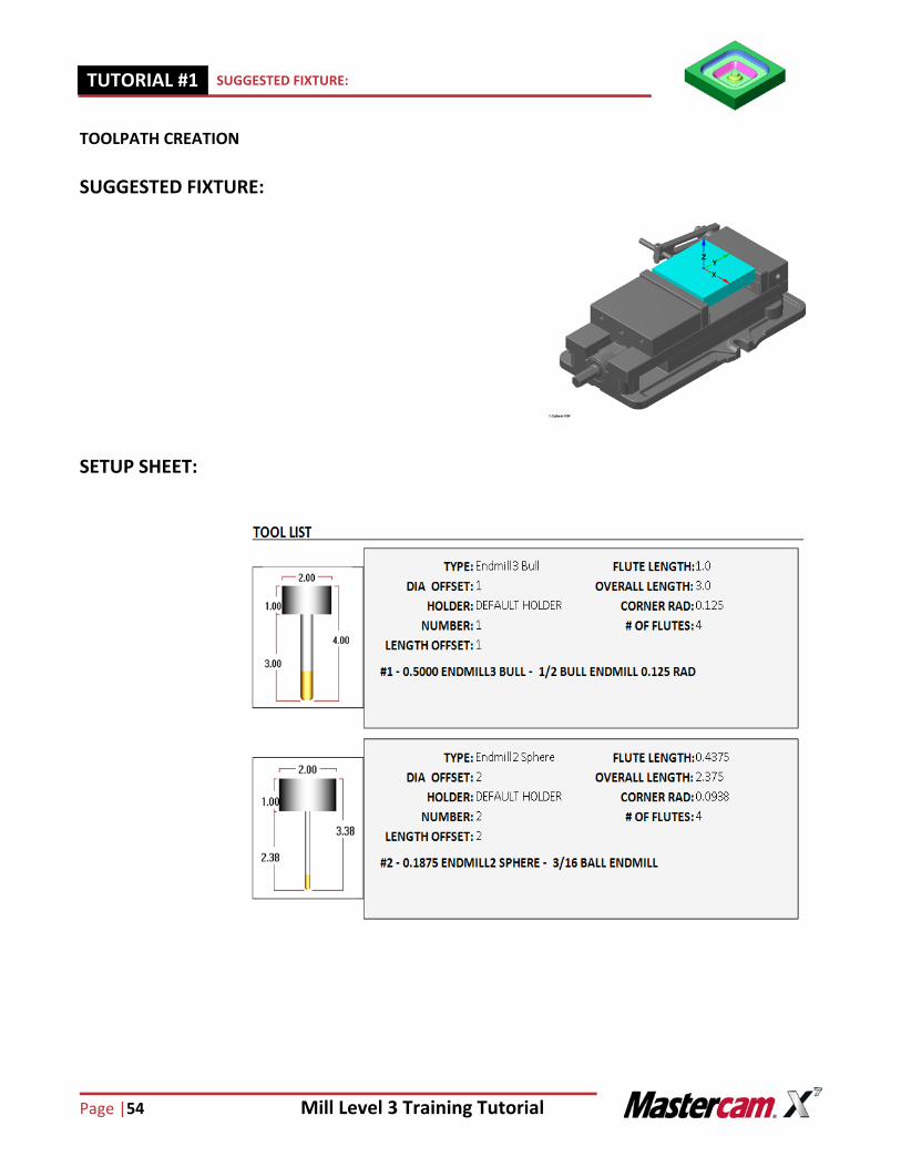
TOOLPATH CREATION
SUGGESTED FIXTURE:
SETUP SHEET:
Mill Level 3 Training Tutorial Page|55
SELECT THE MACHINE AND SET UP THE STOCK TUTORIAL #11
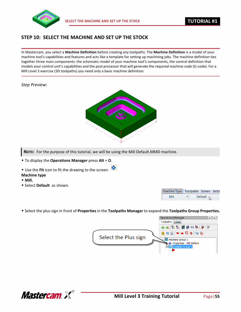
STEP 10: SELECT THE MACHINE AND SET UP THE STOCK
In Mastercam, you select a Machine Definition before creating any toolpaths. The Machine Definition is a model of your machine tool's capabilities and features and acts like a template for setting up machining jobs. The machine definition ties together three main components: the schematic model of your machine tool’s components, the control definition that models your control unit’s capabilities and the post processor that will generate the required machine code (G-code). For a Mill Level 3 exercise (3D toolpaths) you need only a basic machine definition.
Step Preview:
To display the Operations Manager press Alt + O.
Use the Fit icon to fit the drawing to the screen. Machine typeMill. Select Default as shown.
Select the plus sign in front of Properties in the Toolpaths Manager to expand the Toolpaths Group Properties.
NOTE: For the purpose of this tutorial, we will be using the Mill Default.MMD machine.
Page |56 Mill Level 3 Training Tutorial
TUTORIAL #11 SELECT THE MACHINE AND SET UP THE STOCK
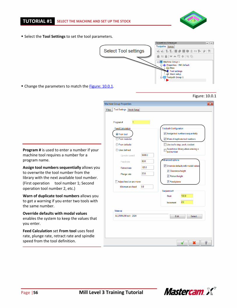
Select the Tool Settings to set the tool parameters.
Change the parameters to match the Figure: 10.0.1.
Figure: 10.0.1
Program # is used to enter a number if your machine tool requires a number for a program name.
Assign tool numbers sequentially allows you to overwrite the tool number from the library with the next available tool number. (First operationtool number 1; Second operation tool number 2, etc.)
Warn of duplicate tool numbers allows you to get a warning if you enter two tools with the same number.
Override defaults with modal values enables the system to keep the values that you enter.
Feed Calculation set From tool uses feed rate, plunge rate, retract rate and spindle speed from the tool definition.
Mill Level 3 Training Tutorial Page|57
SELECT THE MACHINE AND SET UP THE STOCK TUTORIAL #11
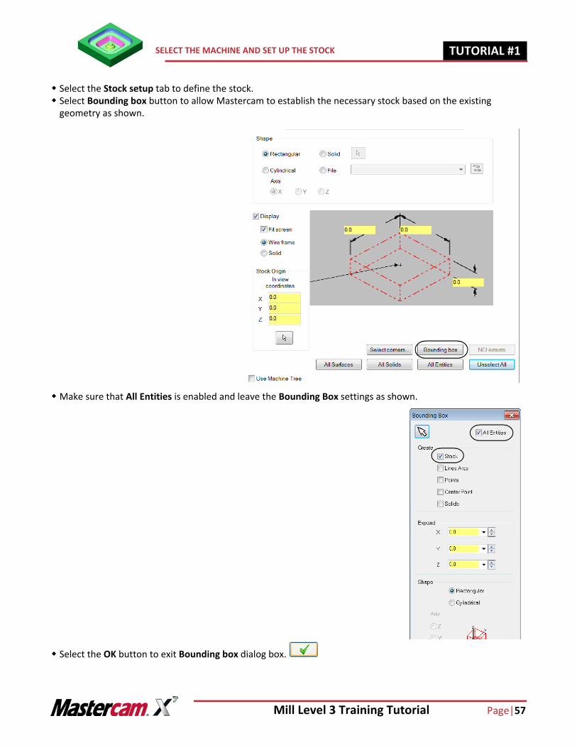
Select the Stock setup tab to define the stock. Select Bounding box button to allow Mastercam to establish the necessary stock based on the existing
geometry as shown.
Make sure that All Entities is enabled and leave the Bounding Box settings as shown.
Select the OK button to exit Bounding box dialog box.
Page |58 Mill Level 3 Training Tutorial
TUTORIAL #11 SELECT THE MACHINE AND SET UP THE STOCK
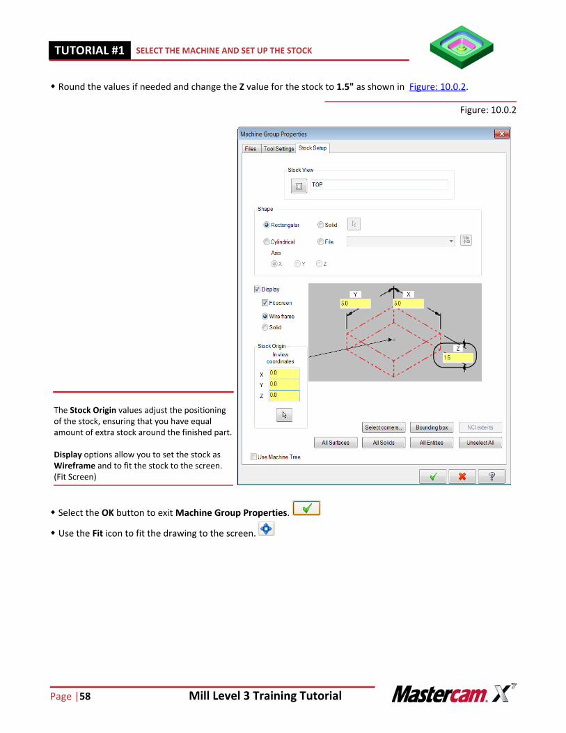
Round the values if needed and change the Z value for the stock to 1.5" as shown in Figure: 10.0.2.
Figure: 10.0.2
Select the OK button to exit Machine Group Properties.
Use the Fit icon to fit the drawing to the screen.
The Stock Origin values adjust the positioning of the stock, ensuring that you have equal amount of extra stock around the finished part.
Display options allow you to set the stock as Wireframe and to fit the stock to the screen. (Fit Screen)
Mill Level 3 Training Tutorial Page|59
ROUGH OUT THE PART USING SURFACE ROUGH POCKET TUTORIAL #11
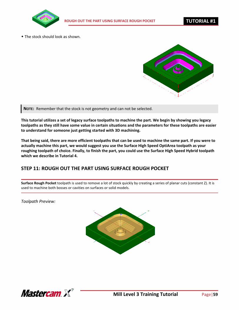
The stock should look as shown.
This tutorial utilizes a set of legacy surface toolpaths to machine the part. We begin by showing you legacy toolpaths as they still have some value in certain situations and the parameters for these toolpaths are easier to understand for someone just getting started with 3D machining.
That being said, there are more efficient toolpaths that can be used to machine the same part. If you were to actually machine this part, we would suggest you use the Surface High Speed OptiArea toolpath as your roughing toolpath of choice. Finally, to finish the part, you could use the Surface High Speed Hybrid toolpath which we describe in Tutorial 4.
STEP 11: ROUGH OUT THE PART USING SURFACE ROUGH POCKET
Surface Rough Pocket toolpath is used to remove a lot of stock quickly by creating a series of planar cuts (constant Z). It is used to machine both bosses or cavities on surfaces or solid models.
Toolpath Preview:
NOTE: Remember that the stock is not geometry and can not be selected.
Page |60 Mill Level 3 Training Tutorial
TUTORIAL #11 ROUGH OUT THE PART USING SURFACE ROUGH POCKET
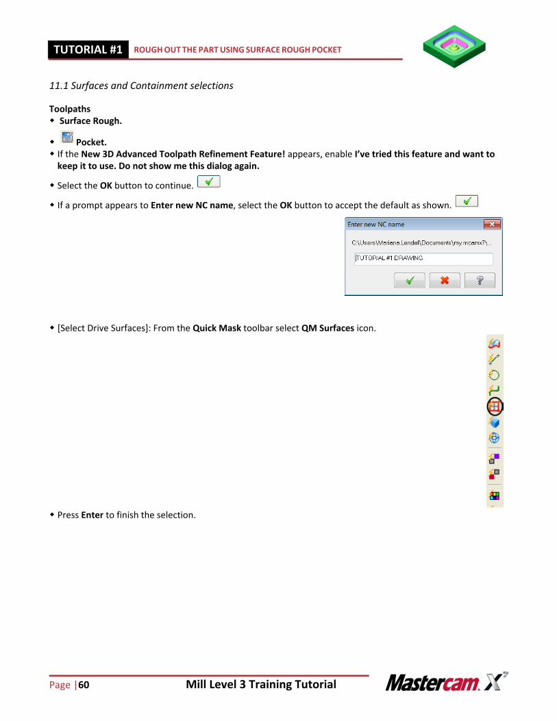
11.1 Surfaces and Containment selections
Toolpaths Surface Rough.
Pocket. If the New 3D Advanced Toolpath Refinement Feature! appears, enable I’ve tried this feature and want to
keep it to use. Do not show me this dialog again.
Select the OK button to continue.
If a prompt appears to Enter new NC name, select the OK button to accept the default as shown.
[Select Drive Surfaces]: From the Quick Mask toolbar select QM Surfaces icon.
Press Enter to finish the selection.
Mill Level 3 Training Tutorial Page|61
ROUGH OUT THE PART USING SURFACE ROUGH POCKET TUTORIAL #11
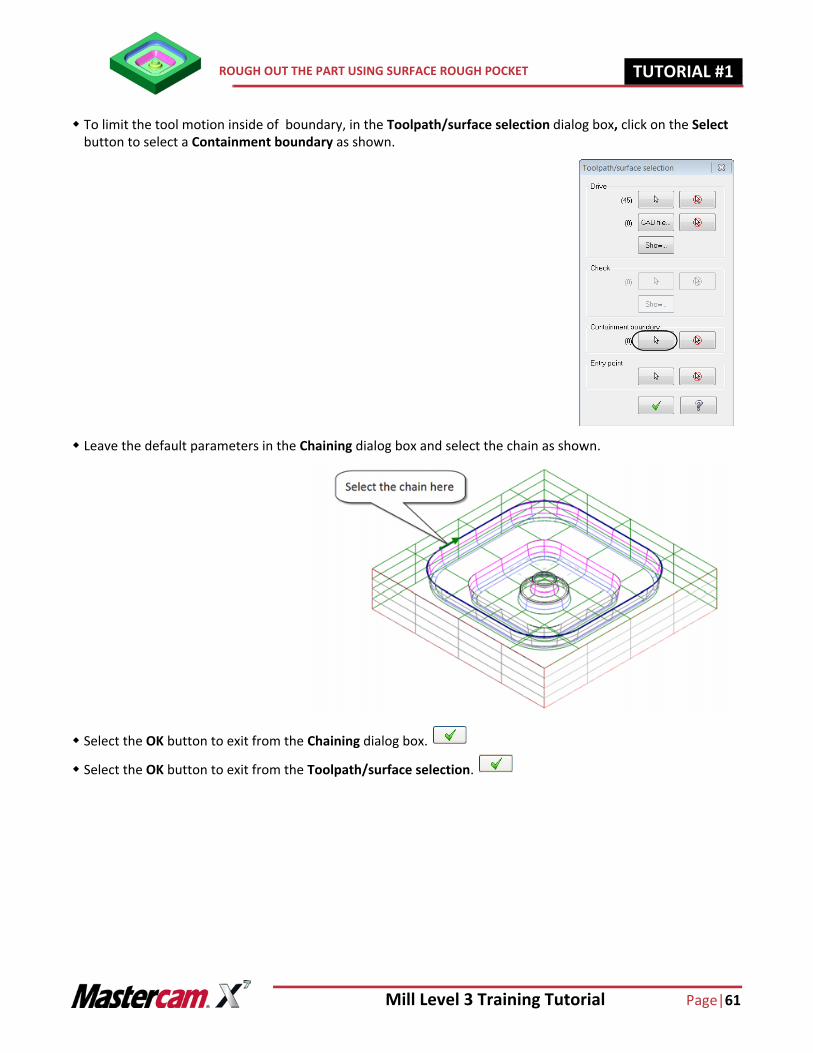
To limit the tool motion inside of boundary, in the Toolpath/surface selection dialog box, click on the Select button to select a Containment boundary as shown.
Leave the default parameters in the Chaining dialog box and select the chain as shown.
Select the OK button to exit from the Chaining dialog box.
Select the OK button to exit from the Toolpath/surface selection.
Page |62 Mill Level 3 Training Tutorial
TUTORIAL #11 ROUGH OUT THE PART USING SURFACE ROUGH POCKET
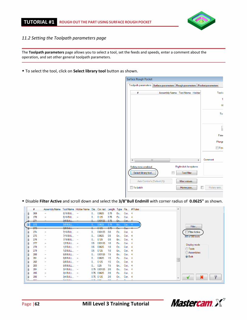
11.2 Setting the Toolpath parameters page
The Toolpath parameters page allows you to select a tool, set the feeds and speeds, enter a comment about the operation, and set other general toolpath parameters.
To select the tool, click on Select library tool button as shown.
Disable Filter Active and scroll down and select the 3/8"Bull Endmill with corner radius of 0.0625" as shown.
Mill Level 3 Training Tutorial Page|63
ROUGH OUT THE PART USING SURFACE ROUGH POCKET TUTORIAL #11
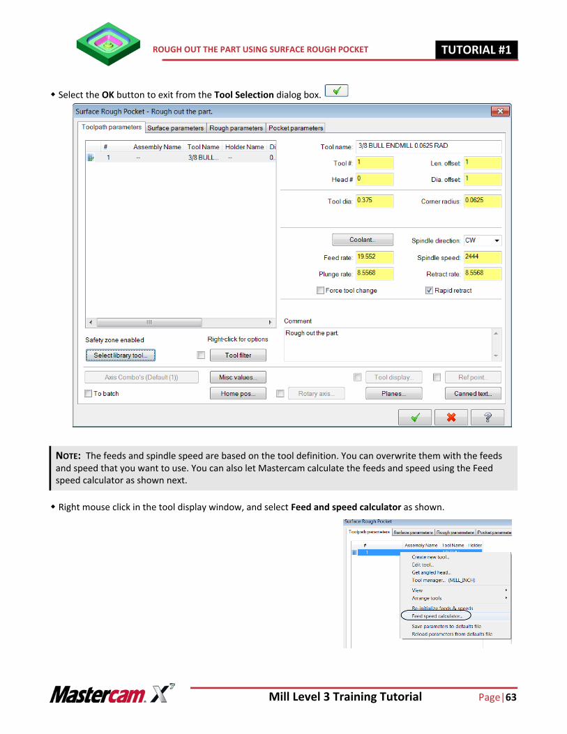
Select the OK button to exit from the Tool Selection dialog box.
Right mouse click in the tool display window, and select Feed and speed calculator as shown.
NOTE: The feeds and spindle speed are based on the tool definition. You can overwrite them with the feeds and speed that you want to use. You can also let Mastercam calculate the feeds and speed using the Feed speed calculator as shown next.
Page |64 Mill Level 3 Training Tutorial
TUTORIAL #11 ROUGH OUT THE PART USING SURFACE ROUGH POCKET
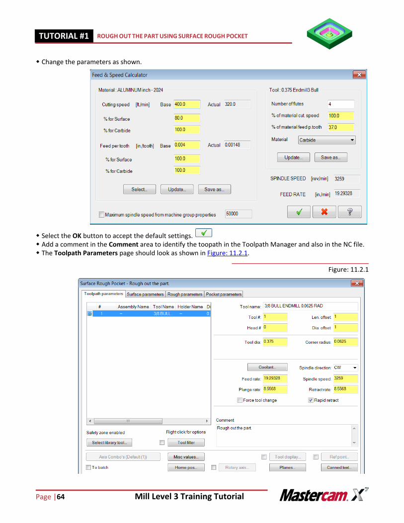
Change the parameters as shown.
Select the OK button to accept the default settings. Add a comment in the Comment area to identify the toopath in the Toolpath Manager and also in the NC file. The Toolpath Parameters page should look as shown in Figure: 11.2.1.
Figure: 11.2.1
Mill Level 3 Training Tutorial Page|65
ROUGH OUT THE PART USING SURFACE ROUGH POCKET TUTORIAL #11
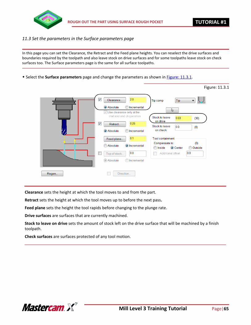
11.3 Set the parameters in the Surface parameters page
In this page you can set the Clearance, the Retract and the Feed plane heights. You can reselect the drive surfaces and boundaries required by the toolpath and also leave stock on drive surfaces and for some toolpaths leave stock on check surfaces too. The Surface parameters page is the same for all surface toolpaths.
Select the Surface parameters page and change the parameters as shown in Figure: 11.3.1.
Figure: 11.3.1
Clearance sets the height at which the tool moves to and from the part.
Retract sets the height at which the tool moves up to before the next pass.
Feed plane sets the height the tool rapids before changing to the plunge rate.
Drive surfaces are surfaces that are currently machined.
Stock to leave on drive sets the amount of stock left on the drive surface that will be machined by a finish toolpath.
Check surfaces are surfaces protected of any tool motion.
Page |66 Mill Level 3 Training Tutorial
TUTORIAL #11 ROUGH OUT THE PART USING SURFACE ROUGH POCKET
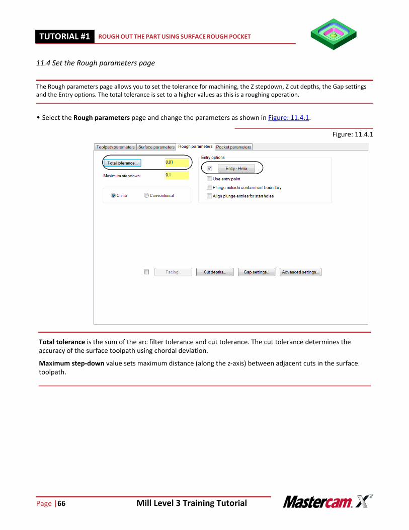
11.4 Set the Rough parameters page
The Rough parameters page allows you to set the tolerance for machining, the Z stepdown, Z cut depths, the Gap settings and the Entry options. The total tolerance is set to a higher values as this is a roughing operation.
Select the Rough parameters page and change the parameters as shown in Figure: 11.4.1.
Figure: 11.4.1
Total tolerance is the sum of the arc filter tolerance and cut tolerance. The cut tolerance determines the accuracy of the surface toolpath using chordal deviation.
Maximum step-down value sets maximum distance (along the z-axis) between adjacent cuts in the surface. toolpath.
Mill Level 3 Training Tutorial Page|67
ROUGH OUT THE PART USING SURFACE ROUGH POCKET TUTORIAL #11
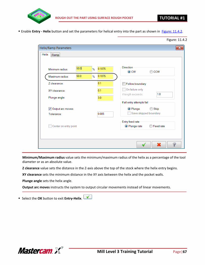
Enable Entry - Helix button and set the parameters for helical entry into the part as shown in Figure: 11.4.2.
Figure: 11.4.2
Select the OK button to exit Entry-Helix.
Minimum/Maximum radius value sets the minimum/maximum radius of the helix as a percentage of the tool diameter or as an absolute value.
Z clearance value sets the distance in the Z-axis above the top of the stock where the helix entry begins.
XY clearance sets the minimum distance in the XY axis between the helix and the pocket walls.
Plunge angle sets the helix angle.
Output arc moves instructs the system to output circular movements instead of linear movements.
Page |68 Mill Level 3 Training Tutorial
TUTORIAL #11 ROUGH OUT THE PART USING SURFACE ROUGH POCKET
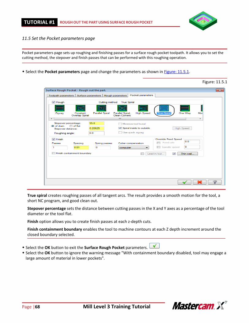
11.5 Set the Pocket parameters page
Pocket parameters page sets up roughing and finishing passes for a surface rough pocket toolpath. It allows you to set the cutting method, the stepover and finish passes that can be performed with this roughing operation.
Select the Pocket parameters page and change the parameters as shown in Figure: 11.5.1.
Figure: 11.5.1
Select the OK button to exit the Surface Rough Pocket parameters. Select the OK button to ignore the warning message "With containment boundary disabled, tool may engage a
large amount of material in lower pockets".
True spiral creates roughing passes of all tangent arcs. The result provides a smooth motion for the tool, a short NC program, and good clean out.
Stepover percentage sets the distance between cutting passes in the X and Y axes as a percentage of the tool diameter or the tool flat.
Finish option allows you to create finish passes at each z-depth cuts.
Finish containment boundary enables the tool to machine contours at each Z depth increment around the closed boundary selected.
Mill Level 3 Training Tutorial Page|69
BACKPLOT THE TOOLPATH TUTORIAL #11
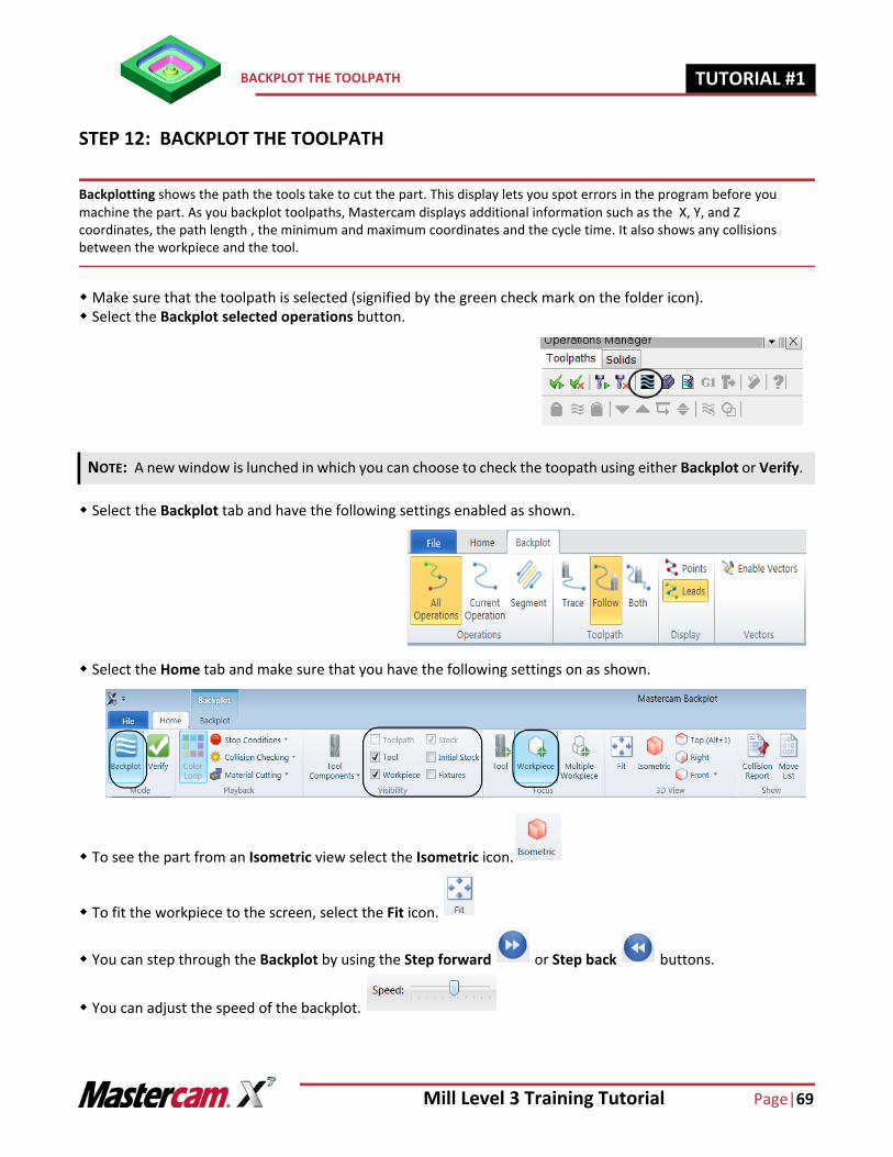
STEP 12: BACKPLOT THE TOOLPATH
Backplotting shows the path the tools take to cut the part. This display lets you spot errors in the program before you machine the part. As you backplot toolpaths, Mastercam displays additional information such as the X, Y, and Z coordinates, the path length , the minimum and maximum coordinates and the cycle time. It also shows any collisions between the workpiece and the tool.
Make sure that the toolpath is selected (signified by the green check mark on the folder icon). Select the Backplot selected operations button.
Select the Backplot tab and have the following settings enabled as shown.
Select the Home tab and make sure that you have the following settings on as shown.
To see the part from an Isometric view select the Isometric icon.
To fit the workpiece to the screen, select the Fit icon.
You can step through the Backplot by using the Step forward or Step back buttons.
You can adjust the speed of the backplot.
NOTE: A new window is lunched in which you can choose to check the toopath using either Backplot or Verify.
Page |70 Mill Level 3 Training Tutorial
TUTORIAL #11 SIMULATE THE TOOLPATH IN VERIFY
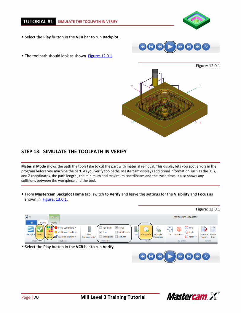
Select the Play button in the VCR bar to run Backplot.
The toolpath should look as shown Figure: 12.0.1.
Figure: 12.0.1
STEP 13: SIMULATE THE TOOLPATH IN VERIFY
Material Mode shows the path the tools take to cut the part with material removal. This display lets you spot errors in the program before you machine the part. As you verify toolpaths, Mastercam displays additional information such as the X, Y, and Z coordinates, the path length , the minimum and maximum coordinates and the cycle time. It also shows any collisions between the workpiece and the tool.
From Mastercam Backplot Home tab, switch to Verify and leave the settings for the Visibility and Focus as shown in Figure: 13.0.1.
Figure: 13.0.1
Select the Play button in the VCR bar to run Verify.
Mill Level 3 Training Tutorial Page|71
SIMULATE THE TOOLPATH IN VERIFY TUTORIAL #11
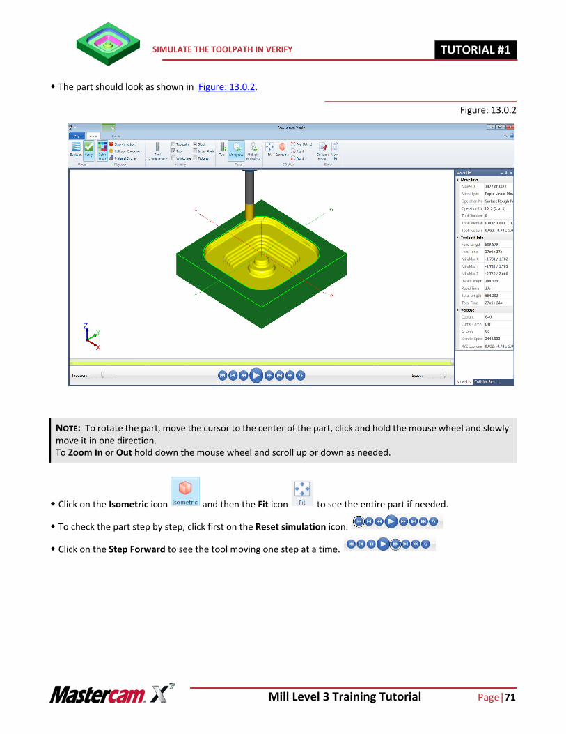
The part should look as shown in Figure: 13.0.2.
Figure: 13.0.2
Click on the Isometric icon and then the Fit icon to see the entire part if needed.
To check the part step by step, click first on the Reset simulation icon.
Click on the Step Forward to see the tool moving one step at a time.
NOTE: To rotate the part, move the cursor to the center of the part, click and hold the mouse wheel and slowly move it in one direction.To Zoom In or Out hold down the mouse wheel and scroll up or down as needed.
Page |72 Mill Level 3 Training Tutorial
TUTORIAL #11 SIMULATE THE TOOLPATH IN VERIFY
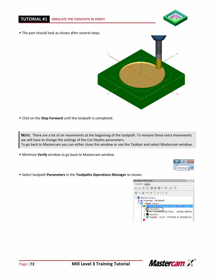
The part should look as shown after several steps.
Click on the Step Forward until the toolpath is completed.
Minimize Verify window to go back to Mastercam window.
Select toolpath Parameters in the Toolpaths Operations Manager as shown.
NOTE: There are a lot of air movements at the beginning of the toolpath. To remove these extra movements we will have to change the settings of the Cut Depths parameters.To go back to Mastercam you can either close this window or use the Taskbar and select Mastercam window.
Mill Level 3 Training Tutorial Page|73
SIMULATE THE TOOLPATH IN VERIFY TUTORIAL #11
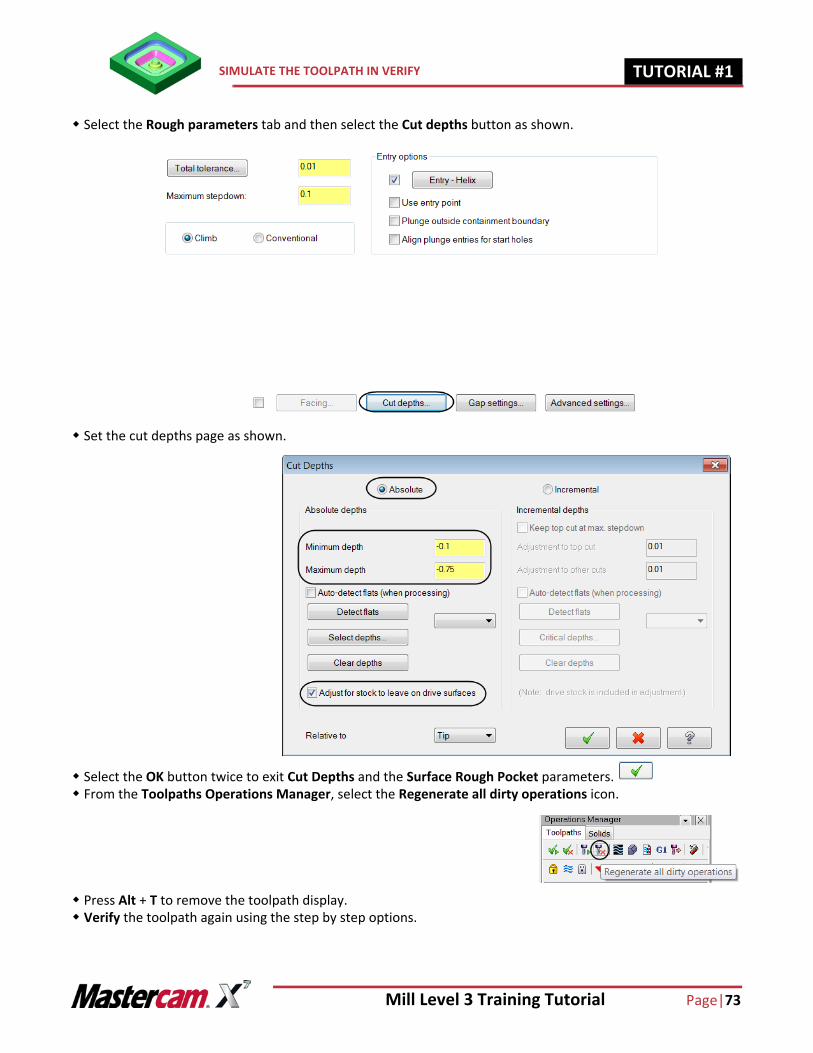
Select the Rough parameters tab and then select the Cut depths button as shown.
Set the cut depths page as shown.
Select the OK button twice to exit Cut Depths and the Surface Rough Pocket parameters. From the Toolpaths Operations Manager, select the Regenerate all dirty operations icon.
Press Alt + T to remove the toolpath display. Verify the toolpath again using the step by step options.
Page |74 Mill Level 3 Training Tutorial
TUTORIAL #11 FINISH THE SHALLOW AREAS USING SURFACE FINISH SHALLOW
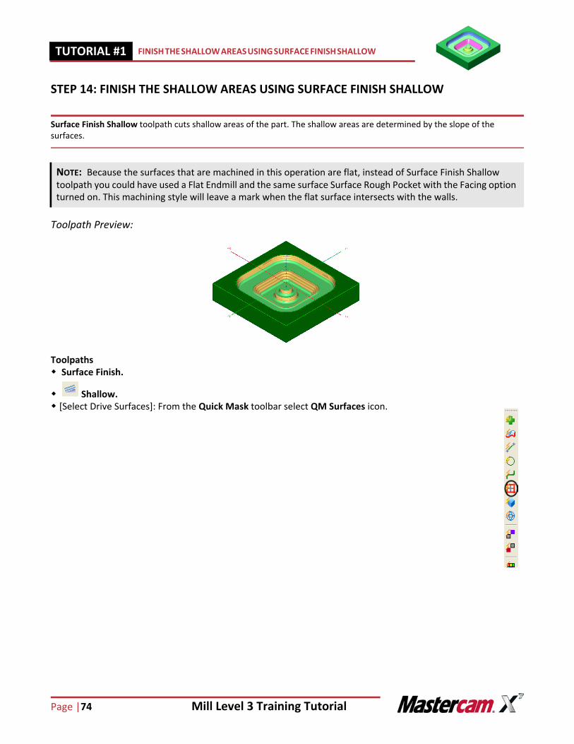
STEP 14: FINISH THE SHALLOW AREAS USING SURFACE FINISH SHALLOW
Surface Finish Shallow toolpath cuts shallow areas of the part. The shallow areas are determined by the slope of the surfaces.
Toolpath Preview:
Toolpaths Surface Finish.
Shallow. [Select Drive Surfaces]: From the Quick Mask toolbar select QM Surfaces icon.
NOTE: Because the surfaces that are machined in this operation are flat, instead of Surface Finish Shallow toolpath you could have used a Flat Endmill and the same surface Surface Rough Pocket with the Facing option turned on. This machining style will leave a mark when the flat surface intersects with the walls.
Mill Level 3 Training Tutorial Page|75
FINISH THE SHALLOW AREAS USING SURFACE FINISH SHALLOW TUTORIAL #11
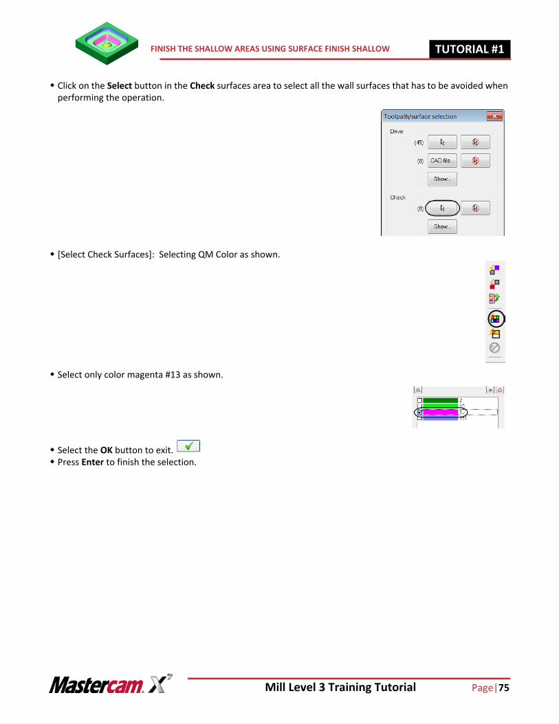
Click on the Select button in the Check surfaces area to select all the wall surfaces that has to be avoided when performing the operation.
[Select Check Surfaces]: Selecting QM Color as shown.
Select only color magenta #13 as shown.
Select the OK button to exit. Press Enter to finish the selection.
Page |76 Mill Level 3 Training Tutorial
TUTORIAL #11 FINISH THE SHALLOW AREAS USING SURFACE FINISH SHALLOW
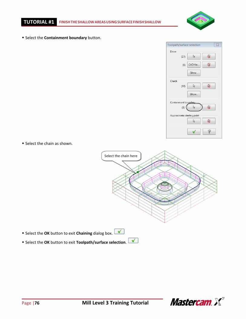
Select the Containment boundary button.
Select the chain as shown.
Select the OK button to exit Chaining dialog box.
Select the OK button to exit Toolpath/surface selection.
Mill Level 3 Training Tutorial Page|77
FINISH THE SHALLOW AREAS USING SURFACE FINISH SHALLOW TUTORIAL #11
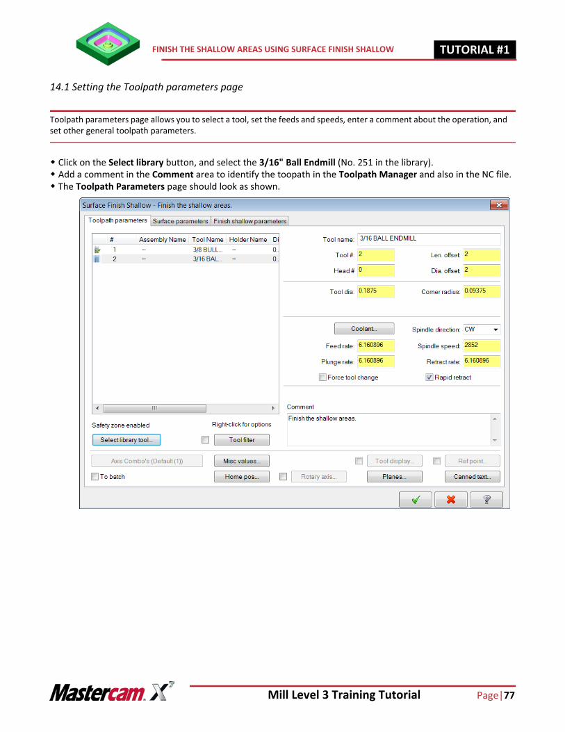
14.1 Setting the Toolpath parameters page
Toolpath parameters page allows you to select a tool, set the feeds and speeds, enter a comment about the operation, and set other general toolpath parameters.
Click on the Select library button, and select the 3/16" Ball Endmill (No. 251 in the library). Add a comment in the Comment area to identify the toopath in the Toolpath Manager and also in the NC file. The Toolpath Parameters page should look as shown.
Page |78 Mill Level 3 Training Tutorial
TUTORIAL #11 FINISH THE SHALLOW AREAS USING SURFACE FINISH SHALLOW
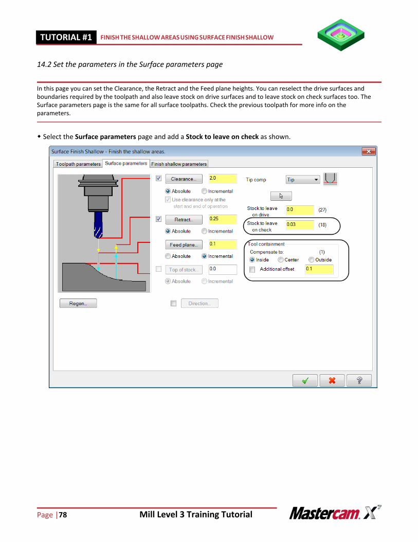
14.2 Set the parameters in the Surface parameters page
In this page you can set the Clearance, the Retract and the Feed plane heights. You can reselect the drive surfaces and boundaries required by the toolpath and also leave stock on drive surfaces and to leave stock on check surfaces too. The Surface parameters page is the same for all surface toolpaths. Check the previous toolpath for more info on the parameters.
Select the Surface parameters page and add a Stock to leave on check as shown.
Mill Level 3 Training Tutorial Page|79
FINISH THE SHALLOW AREAS USING SURFACE FINISH SHALLOW TUTORIAL #11
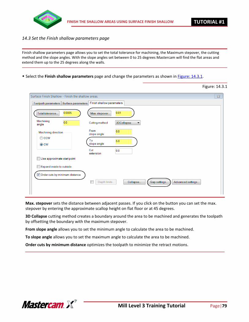
14.3 Set the Finish shallow parameters page
Finish shallow parameters page allows you to set the total tolerance for machining, the Maximum stepover, the cutting method and the slope angles. With the slope angles set between 0 to 25 degrees Mastercam will find the flat areas and extend them up to the 25 degrees along the walls.
Select the Finish shallow parameters page and change the parameters as shown in Figure: 14.3.1.
Figure: 14.3.1
Max. stepover sets the distance between adjacent passes. If you click on the button you can set the max. stepover by entering the approximate scallop height on flat floor or at 45 degrees.
3D Collapse cutting method creates a boundary around the area to be machined and generates the toolpath by offsetting the boundary with the maximum stepover.
From slope angle allows you to set the minimum angle to calculate the area to be machined.
To slope angle allows you to set the maximum angle to calculate the area to be machined.
Order cuts by minimum distance optimizes the toolpath to minimize the retract motions.
Page |80 Mill Level 3 Training Tutorial
TUTORIAL #11 FINISH THE SHALLOW AREAS USING SURFACE FINISH SHALLOW
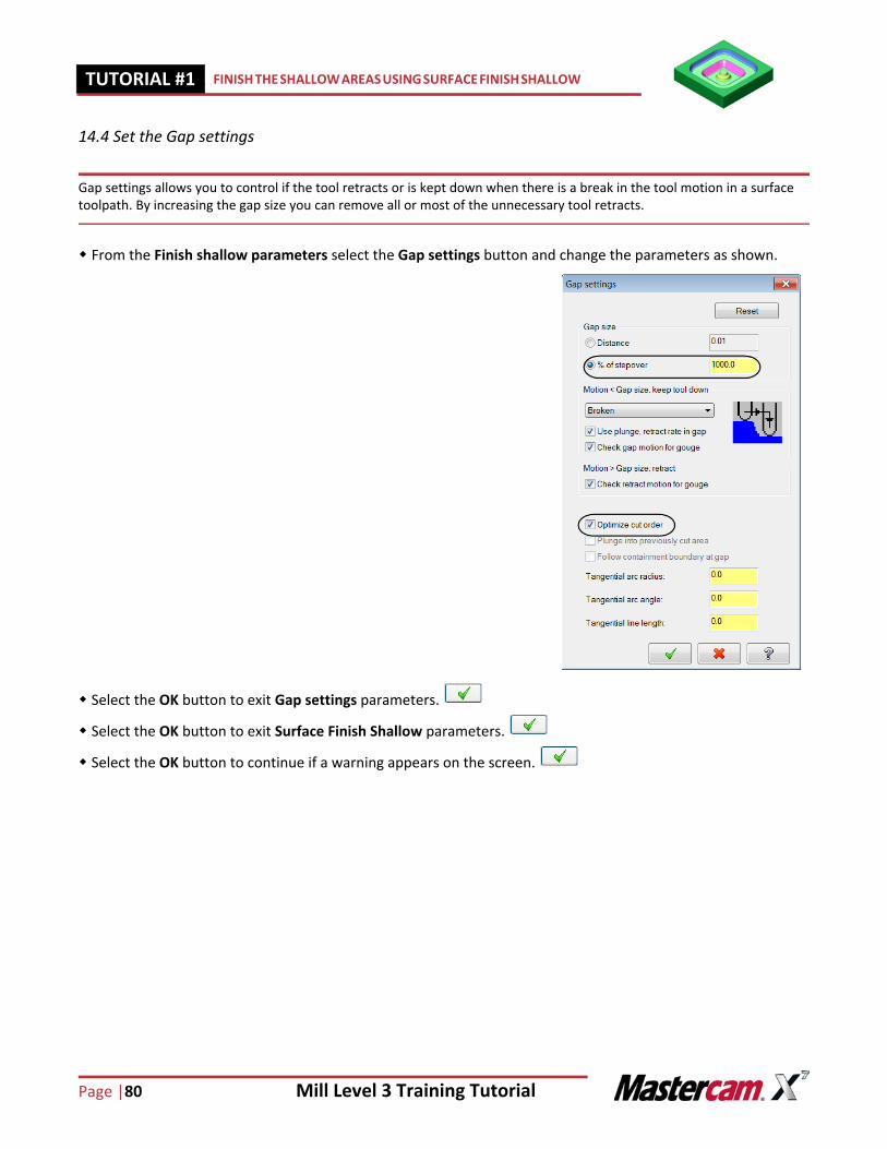
14.4 Set the Gap settings
Gap settings allows you to control if the tool retracts or is kept down when there is a break in the tool motion in a surface toolpath. By increasing the gap size you can remove all or most of the unnecessary tool retracts.
From the Finish shallow parameters select the Gap settings button and change the parameters as shown.
Select the OK button to exit Gap settings parameters.
Select the OK button to exit Surface Finish Shallow parameters.
Select the OK button to continue if a warning appears on the screen.
Mill Level 3 Training Tutorial Page|81
FINISH THE SHALLOW AREAS USING SURFACE FINISH SHALLOW TUTORIAL #11
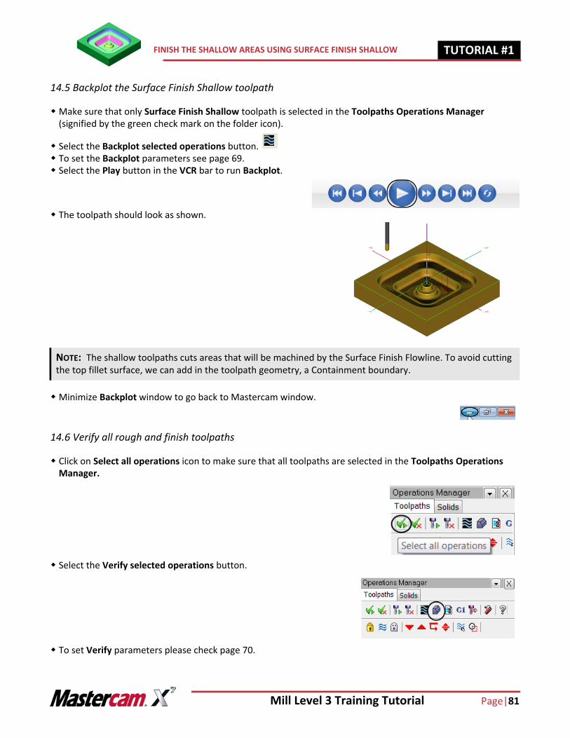
14.5 Backplot the Surface Finish Shallow toolpath
Make sure that only Surface Finish Shallow toolpath is selected in the Toolpaths Operations Manager (signified by the green check mark on the folder icon).
Select the Backplot selected operations button. To set the Backplot parameters see page 69. Select the Play button in the VCR bar to run Backplot.
The toolpath should look as shown.
Minimize Backplot window to go back to Mastercam window.
14.6 Verify all rough and finish toolpaths
Click on Select all operations icon to make sure that all toolpaths are selected in the Toolpaths Operations Manager.
Select the Verify selected operations button.
To set Verify parameters please check page 70.
NOTE: The shallow toolpaths cuts areas that will be machined by the Surface Finish Flowline. To avoid cutting the top fillet surface, we can add in the toolpath geometry, a Containment boundary.
Page |82 Mill Level 3 Training Tutorial
TUTORIAL #11 FINISH THE WALLS USING CONTOUR TOOLPATH
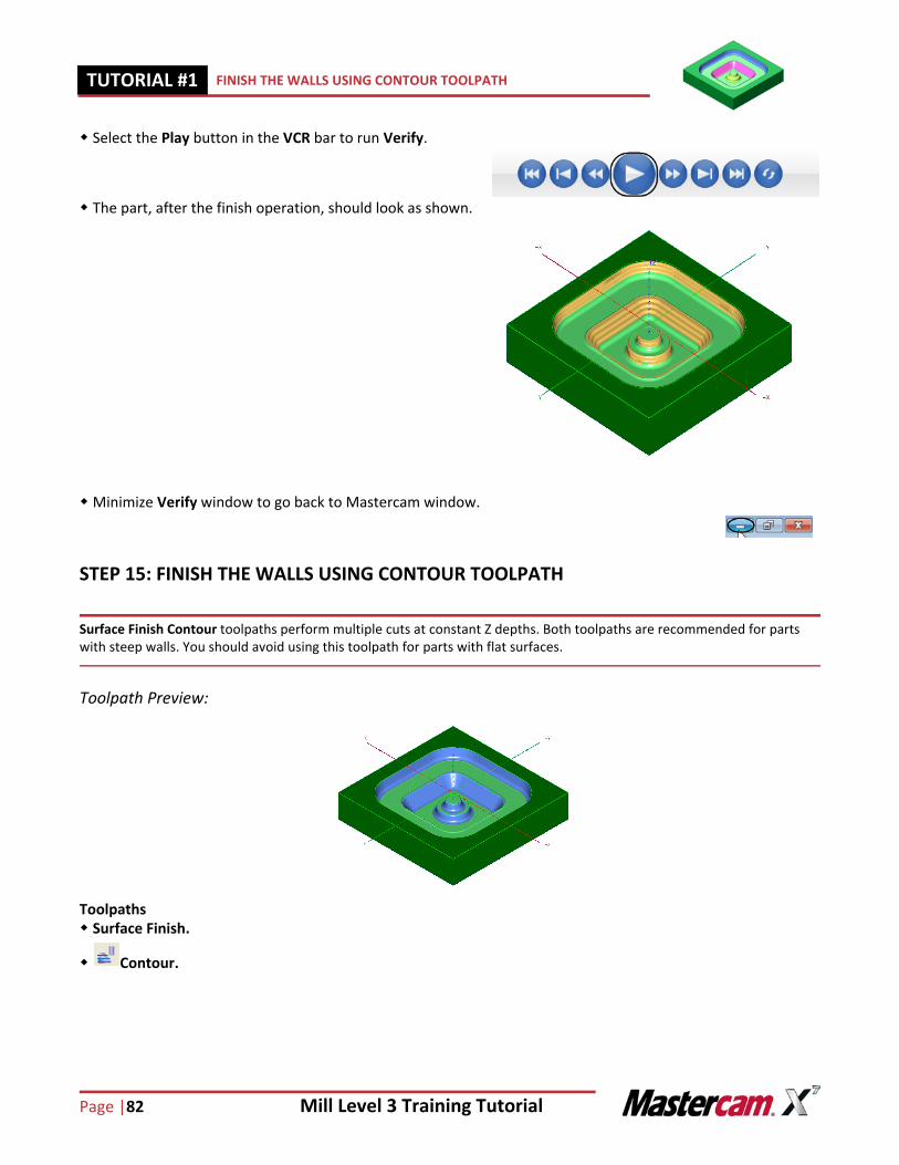
Select the Play button in the VCR bar to run Verify.
The part, after the finish operation, should look as shown.
Minimize Verify window to go back to Mastercam window.
STEP 15: FINISH THE WALLS USING CONTOUR TOOLPATH
Surface Finish Contour toolpaths perform multiple cuts at constant Z depths. Both toolpaths are recommended for parts with steep walls. You should avoid using this toolpath for parts with flat surfaces.
Toolpath Preview:
Toolpaths Surface Finish.
Contour.
Mill Level 3 Training Tutorial Page|83
FINISH THE WALLS USING CONTOUR TOOLPATH TUTORIAL #11
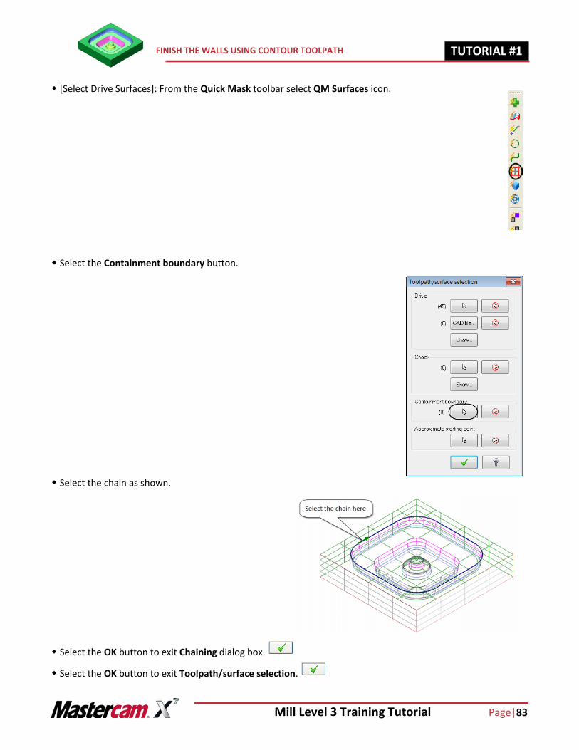
[Select Drive Surfaces]: From the Quick Mask toolbar select QM Surfaces icon.
Select the Containment boundary button.
Select the chain as shown.
Select the OK button to exit Chaining dialog box.
Select the OK button to exit Toolpath/surface selection.
Page |84 Mill Level 3 Training Tutorial
TUTORIAL #11 FINISH THE WALLS USING CONTOUR TOOLPATH
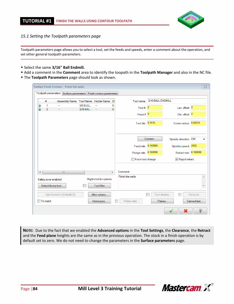
15.1 Setting the Toolpath parameters page
Toolpath parameters page allows you to select a tool, set the feeds and speeds, enter a comment about the operation, and set other general toolpath parameters.
Select the same 3/16" Ball Endmill. Add a comment in the Comment area to identify the toopath in the Toolpath Manager and also in the NC file. The Toolpath Parameters page should look as shown.
NOTE: Due to the fact that we enabled the Advanced options in the Tool Settings, the Clearance, the Retract and the Feed plane heights are the same as in the previous operation. The stock in a finish operation is by default set to zero. We do not need to change the parameters in the Surface parameters page.
Mill Level 3 Training Tutorial Page|85
FINISH THE WALLS USING CONTOUR TOOLPATH TUTORIAL #11
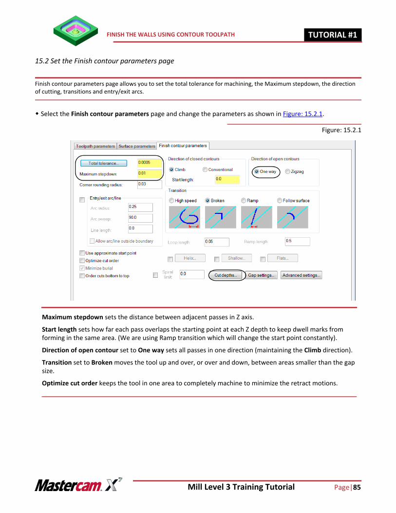
15.2 Set the Finish contour parameters page
Finish contour parameters page allows you to set the total tolerance for machining, the Maximum stepdown, the direction of cutting, transitions and entry/exit arcs.
Select the Finish contour parameters page and change the parameters as shown in Figure: 15.2.1.
Figure: 15.2.1
Maximum stepdown sets the distance between adjacent passes in Z axis.
Start length sets how far each pass overlaps the starting point at each Z depth to keep dwell marks from forming in the same area. (We are using Ramp transition which will change the start point constantly).
Direction of open contour set to One way sets all passes in one direction (maintaining the Climb direction).
Transition set to Broken moves the tool up and over, or over and down, between areas smaller than the gap size.
Optimize cut order keeps the tool in one area to completely machine to minimize the retract motions.
Page |86 Mill Level 3 Training Tutorial
TUTORIAL #11 FINISH THE WALLS USING CONTOUR TOOLPATH
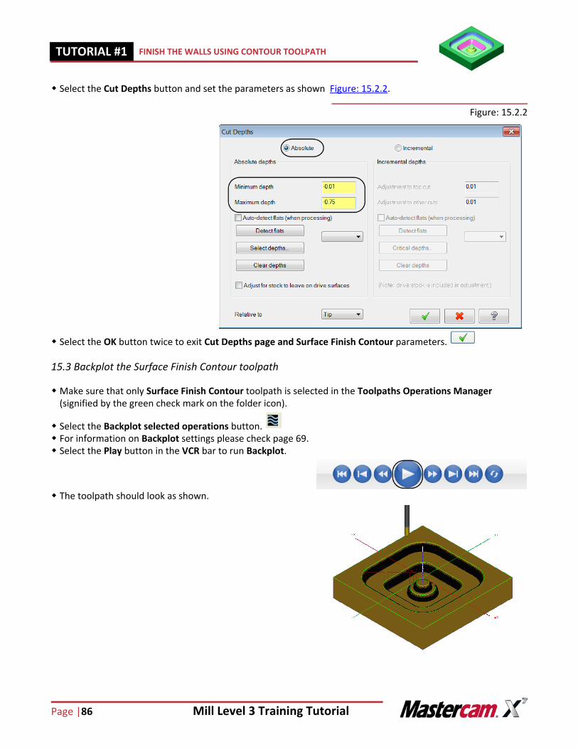
Select the Cut Depths button and set the parameters as shown Figure: 15.2.2.
Figure: 15.2.2
Select the OK button twice to exit Cut Depths page and Surface Finish Contour parameters.
15.3 Backplot the Surface Finish Contour toolpath
Make sure that only Surface Finish Contour toolpath is selected in the Toolpaths Operations Manager (signified by the green check mark on the folder icon).
Select the Backplot selected operations button. For information on Backplot settings please check page 69. Select the Play button in the VCR bar to run Backplot.
The toolpath should look as shown.
Mill Level 3 Training Tutorial Page|87
FINISH THE WALLS USING CONTOUR TOOLPATH TUTORIAL #11
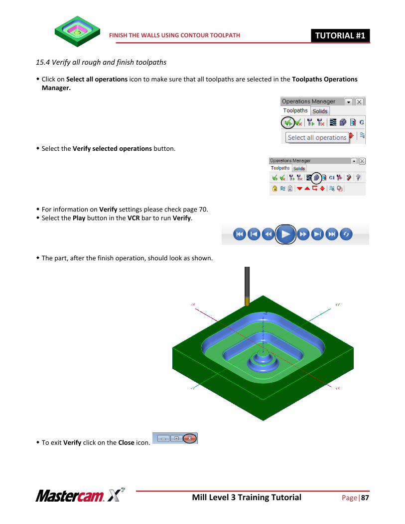
15.4 Verify all rough and finish toolpaths
Click on Select all operations icon to make sure that all toolpaths are selected in the Toolpaths Operations Manager.
Select the Verify selected operations button.
For information on Verify settings please check page 70. Select the Play button in the VCR bar to run Verify.
The part, after the finish operation, should look as shown.
To exit Verify click on the Close icon.
Page |88 Mill Level 3 Training Tutorial
TUTORIAL #11 POST PROCESS THE FILE
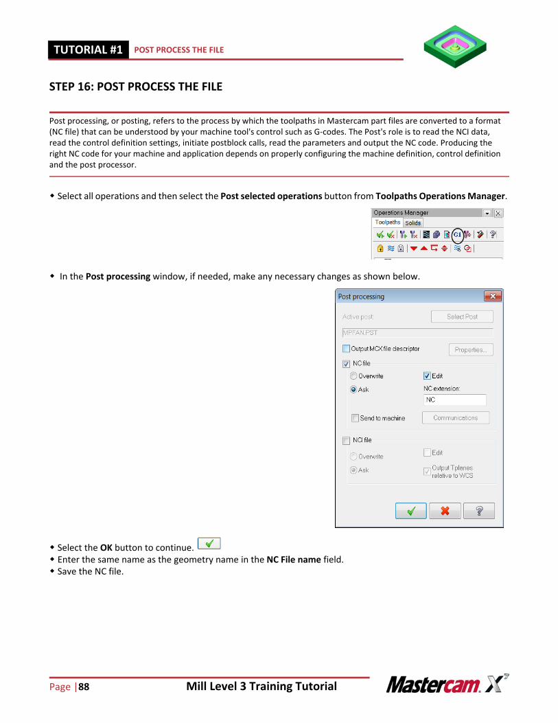
STEP 16: POST PROCESS THE FILE
Post processing, or posting, refers to the process by which the toolpaths in Mastercam part files are converted to a format (NC file) that can be understood by your machine tool's control such as G-codes. The Post's role is to read the NCI data, read the control definition settings, initiate postblock calls, read the parameters and output the NC code. Producing the right NC code for your machine and application depends on properly configuring the machine definition, control definition and the post processor.
Select all operations and then select the Post selected operations button from Toolpaths Operations Manager.
In the Post processing window, if needed, make any necessary changes as shown below.
Select the OK button to continue. Enter the same name as the geometry name in the NC File name field. Save the NC file.
Mill Level 3 Training Tutorial Page|89
SAVE THE UPDATED MCX FILE TUTORIAL #11
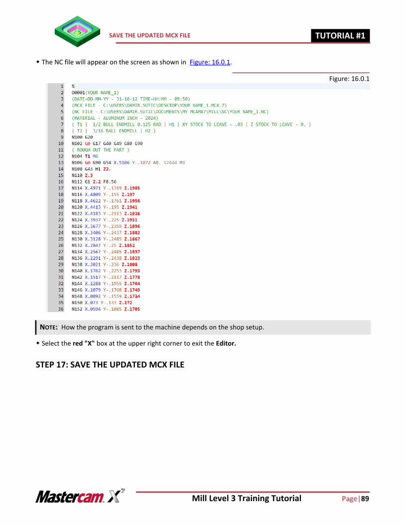
The NC file will appear on the screen as shown in Figure: 16.0.1.
Figure: 16.0.1
Select the red "X" box at the upper right corner to exit the Editor.
STEP 17: SAVE THE UPDATED MCX FILE
NOTE: How the program is sent to the machine depends on the shop setup.
Page |90 Mill Level 3 Training Tutorial
TUTORIAL #11 SAVE THE UPDATED MCX FILE
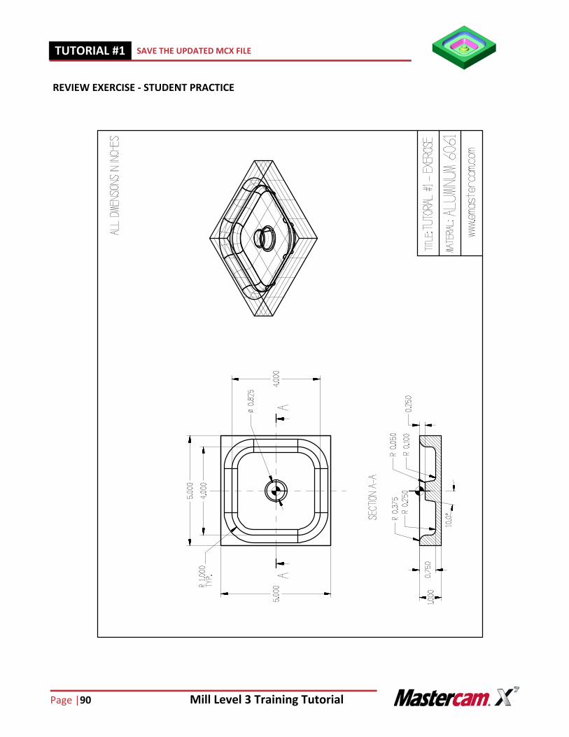
REVIEW EXERCISE - STUDENT PRACTICE
Mill Level 3 Training Tutorial Page|91
CREATE THE GEOMETRY FOR TUTORIAL #1 EXERCISE TUTORIAL #11
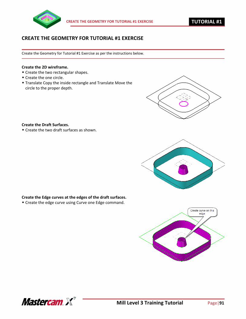
CREATE THE GEOMETRY FOR TUTORIAL #1 EXERCISE
Create the Geometry for Tutorial #1 Exercise as per the instructions below.
Create the 2D wireframe. Create the two rectangular shapes. Create the one circle. Translate Copy the inside rectangle and Translate Move the
circle to the proper depth.
Create the Draft Surfaces. Create the two draft surfaces as shown.
Create the Edge curves at the edges of the draft surfaces. Create the edge curve using Curve one Edge command.
Page |92 Mill Level 3 Training Tutorial
TUTORIAL #11 CREATE THE GEOMETRY FOR TUTORIAL #1 EXERCISE
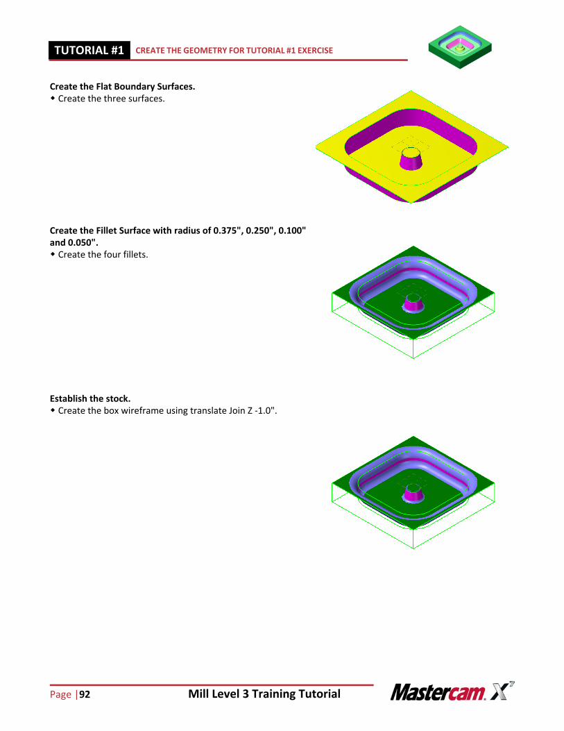
Create the Flat Boundary Surfaces. Create the three surfaces.
Create the Fillet Surface with radius of 0.375", 0.250", 0.100" and 0.050". Create the four fillets.
Establish the stock. Create the box wireframe using translate Join Z -1.0".
Mill Level 3 Training Tutorial Page|93
CREATE THE TOOLPATHS FOR TUTORIAL #1 EXERCISE TUTORIAL #11
CREATE THE TOOLPATHS FOR TUTORIAL #1 EXERCISE
Create the Toolpaths for Tutorial #1 Exercise as per the instructions below.
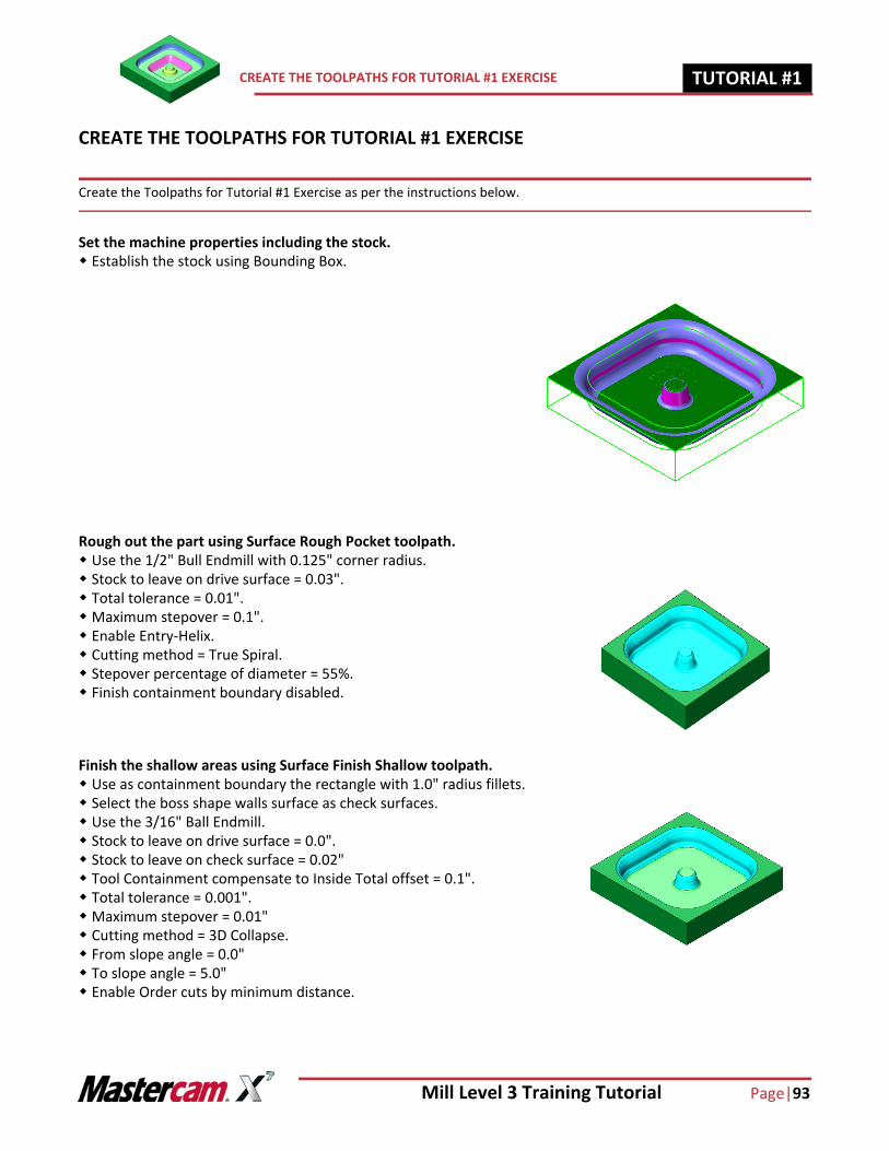
Set the machine properties including the stock. Establish the stock using Bounding Box.
Rough out the part using Surface Rough Pocket toolpath. Use the 1/2" Bull Endmill with 0.125" corner radius. Stock to leave on drive surface = 0.03". Total tolerance = 0.01".Maximum stepover = 0.1". Enable Entry-Helix. Cutting method = True Spiral. Stepover percentage of diameter = 55%. Finish containment boundary disabled.
Finish the shallow areas using Surface Finish Shallow toolpath. Use as containment boundary the rectangle with 1.0" radius fillets. Select the boss shape walls surface as check surfaces. Use the 3/16" Ball Endmill. Stock to leave on drive surface = 0.0". Stock to leave on check surface = 0.02" Tool Containment compensate to Inside Total offset = 0.1". Total tolerance = 0.001".Maximum stepover = 0.01" Cutting method = 3D Collapse. From slope angle = 0.0" To slope angle = 5.0" Enable Order cuts by minimum distance.
Page |94 Mill Level 3 Training Tutorial
TUTORIAL #11 CREATE THE TOOLPATHS FOR TUTORIAL #1 EXERCISE
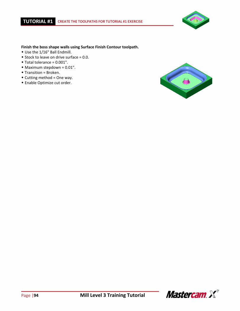
Finish the boss shape walls using Surface Finish Contour toolpath. Use the 1/16" Ball Endmill. Stock to leave on drive surface = 0.0. Total tolerance = 0.001".Maximum stepdown = 0.01". Transition = Broken. Cutting method = One way. Enable Optimize cut order.
Mill Level 3 Training Tutorial Page|95
NOTES: TUTORIAL #11
NOTES:

Page |96 Mill Level 3 Training Tutorial
TUTORIAL #11 NOTES:
TUTORIAL #1 QUIZ
What command allows you to create geometry on one edge of a surface?
What is a draft surface?
How should the surface normals be oriented for the two sets of surfaces between which we want to create a fillet surface?
When would you use a "surface finish contour" toolpath?
When would you use a "surface finish shallow" toolpath?
Mill Level 3 Training Tutorial Page|885
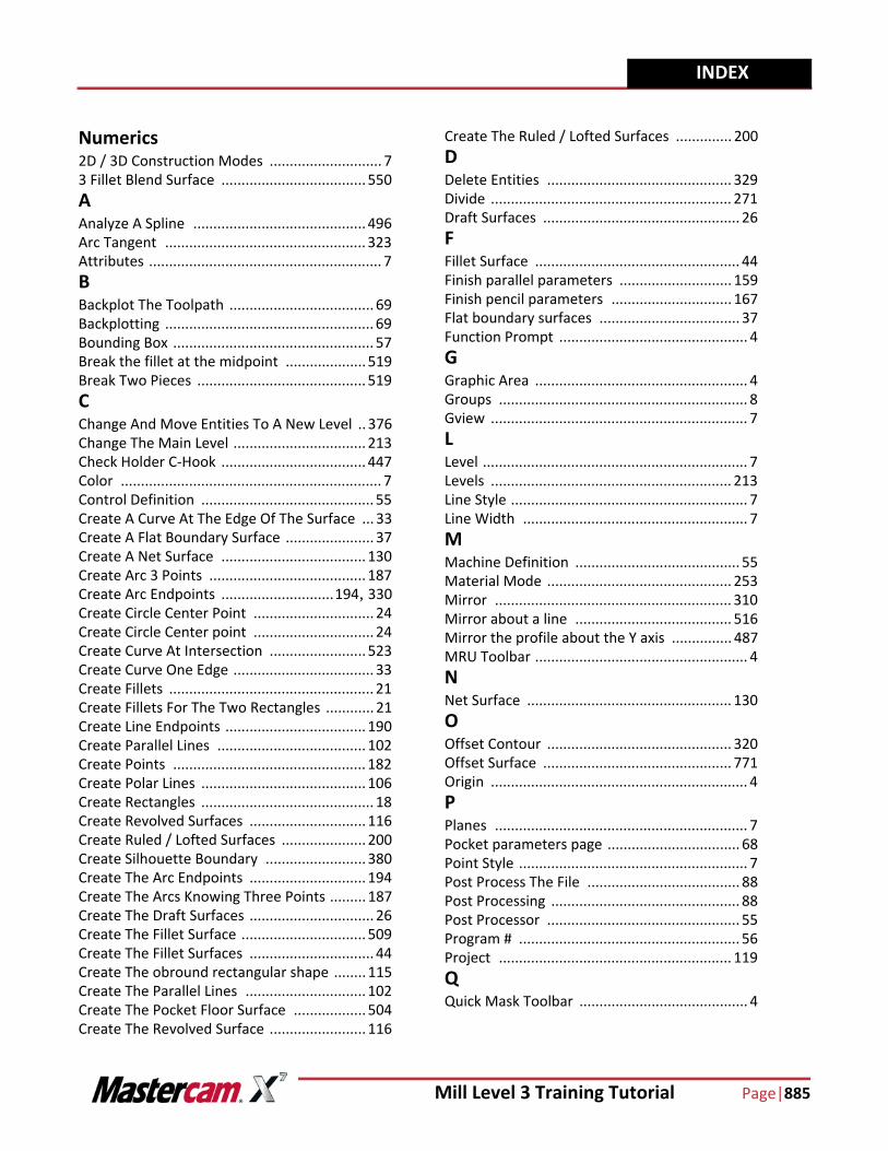
INDEX
Numerics2D / 3D Construction Modes ............................ 73 Fillet Blend Surface .................................... 550AAnalyze A Spline ........................................... 496Arc Tangent .................................................. 323Attributes .......................................................... 7BBackplot The Toolpath .................................... 69Backplotting .................................................... 69Bounding Box .................................................. 57Break the fillet at the midpoint .................... 519Break Two Pieces .......................................... 519CChange And Move Entities To A New Level .. 376Change The Main Level ................................. 213Check Holder C-Hook .................................... 447Color ................................................................. 7Control Definition ........................................... 55Create A Curve At The Edge Of The Surface ... 33Create A Flat Boundary Surface ...................... 37Create A Net Surface .................................... 130Create Arc 3 Points ....................................... 187Create Arc Endpoints ............................194, 330Create Circle Center Point .............................. 24Create Circle Center point .............................. 24Create Curve At Intersection ........................ 523Create Curve One Edge ................................... 33Create Fillets ................................................... 21Create Fillets For The Two Rectangles ............ 21Create Line Endpoints ................................... 190Create Parallel Lines ..................................... 102Create Points ................................................ 182Create Polar Lines ......................................... 106Create Rectangles ........................................... 18Create Revolved Surfaces ............................. 116Create Ruled / Lofted Surfaces ..................... 200Create Silhouette Boundary ......................... 380Create The Arc Endpoints ............................. 194Create The Arcs Knowing Three Points ......... 187Create The Draft Surfaces ............................... 26Create The Fillet Surface ............................... 509Create The Fillet Surfaces ............................... 44Create The obround rectangular shape ........ 115Create The Parallel Lines .............................. 102Create The Pocket Floor Surface .................. 504Create The Revolved Surface ........................ 116
Create The Ruled / Lofted Surfaces .............. 200DDelete Entities .............................................. 329Divide ............................................................ 271Draft Surfaces ................................................. 26FFillet Surface ................................................... 44Finish parallel parameters ............................ 159Finish pencil parameters .............................. 167Flat boundary surfaces ................................... 37Function Prompt ............................................... 4GGraphic Area ..................................................... 4Groups .............................................................. 8Gview ................................................................ 7LLevel .................................................................. 7Levels ............................................................ 213Line Style ........................................................... 7Line Width ........................................................ 7MMachine Definition ......................................... 55Material Mode .............................................. 253Mirror ........................................................... 310Mirror about a line ....................................... 516Mirror the profile about the Y axis ............... 487MRU Toolbar ..................................................... 4NNet Surface ................................................... 130OOffset Contour .............................................. 320Offset Surface ............................................... 771Origin ................................................................ 4PPlanes ............................................................... 7Pocket parameters page ................................. 68Point Style ......................................................... 7Post Process The File ...................................... 88Post Processing ............................................... 88Post Processor ................................................ 55Program # ....................................................... 56Project .......................................................... 119QQuick Mask Toolbar .......................................... 4
Page |886 Mill Level 3 Training Tutorial
INDEX
RRest Material ................................................ 246Ribbon Bar ........................................................ 4Rotate - Copy ................................................ 207Rotate - Copy The Surfaces ...................207, 553Rough parameters page ................................. 66SScale .................................................................. 4Select The Machine And Set Up The Stock ..... 55Setup the stock model .................................. 229Simulate the toolpath in Verify ...................... 70Status Bar .......................................................... 4Steep/shallow ............................................... 248Stock Models ................................................ 229Stock Origin .................................................... 58Surface Extend .............................................. 365Surface Finish Blend ..................................... 268Surface Finish Leftover .........................437, 845Surface Finish Parallel ................................... 155Surface Finish Pencil ..................................... 163Surface Finish Scallop ................................... 835Surface Finish Shallow .................................... 74Surface High Speed Scallop .......................... 586Surface High Speed Core Roughing ......234, 565Surface High Speed Finish Horizontal ........... 694Surface High Speed Finish Spiral ................... 605Surface High Speed Hybrid ........................... 424Surface High Speed OptiArea ...............389, 808Surface High Speed OptiCore ....................... 677
Surface High Speed Pencil ............................ 722Surface High Speed Radial ............................ 258Surface High Speed Raster ............................ 712Surface High Speed Rest Roughing ............... 823Surface High Speed Restmill ......................... 407Surface High Speed Waterline ...................... 618Surface Rough Pocket .............................59, 141Surface Rough Pocket Toolpath .................... 141Surface Rough Project .................................. 857Swept Surface ............................................... 333TToolbars ............................................................ 4Toolpath parameters page ............................. 62Toolpaths/Solids Operations Manager ............. 4Transform Toolpaths .................................... 279Transitions .................................................... 247Translate - Join .............................................. 192Trim 1 Entity ................................................. 326Trim 2 Entities .......................................107, 111Trim the draft surfacesto the curve .............. 525Trim The Geometry ...................................... 107Trim The Surfaces ......................................... 523VView Port XYZ Axes ........................................... 5WWork Coordinate System (WCS) ....................... 8ZZ Depth ............................................................. 7