Embed Size (px)
Citation preview

SAMPLE ANALYSIS DATA QUALITY ASSURANCE PROJECT PLAN (SADQ) AT THE
PORTSMOUTH GASEOUS DIFFUSION PLANT, PIKETON, OHIO
U.S. Department of Energy DOE/PPPO/03-0278&D2
February 2014
This document has been approved for public release by:
Henry Thomas 1-21-2014 Classification & Information Officer Date

This page is intentionally left blank.

SAMPLE ANALYSIS DATA QUALITY ASSURANCE PROJECT PLAN AT THE PORTSMOUTH GASEOUS DIFFUSION PLANT, PIKETON, OHIO
DOE/PPPO/03-0278&D2 FBP-ER-PRO-WD-PL-0006, Revision 6
February 2014 Page 1 of 240
FBP/SADQ D2 R6 MASTER/2/12/2014 12:51 PM
SAMPLE ANALYSIS DATA QUALITY ASSURANCE PROJECT PLAN (SADQ) AT THE
PORTSMOUTH GASEOUS DIFFUSION PLANT, PIKETON, OHIO
U.S. Department of Energy DOE/PPPO/03-0278&D2
February 2014
Prepared for U.S. Department of Energy
Prepared by Fluor-B&W Portsmouth LLC, Under Contract DE-AC30-10CC40017
FBP-ER-PRO-WD-PL-0006, Revision 6

SAMPLE ANALYSIS DATA QUALITY ASSURANCE PROJECT PLAN AT THE PORTSMOUTH GASEOUS DIFFUSION PLANT, PIKETON, OHIO
DOE/PPPO/03-0278&D2 FBP-ER-PRO-WD-PL-0006, Revision 6
February 2014 Page 2 of 240
FBP/SADQ D2 R6 MASTER/2/12/2014 12:51 PM
This page is intentionally left blank.


SAMPLE ANALYSIS DATA QUALITY ASSURANCE PROJECT PLAN AT THE PORTSMOUTH GASEOUS DIFFUSION PLANT, PIKETON, OHIO
DOE/PPPO/03-0278&D2 FBP-ER-PRO-WD-PL-0006, Revision 6
February 2014 Page 4 of 240
FBP/SADQ D2 R6 MASTER/2/12/2014 12:51 PM
This page is intentionally left blank.

SAMPLE ANALYSIS DATA QUALITY ASSURANCE PROJECT PLAN AT THE PORTSMOUTH GASEOUS DIFFUSION PLANT, PIKETON, OHIO
DOE/PPPO/03-0278&D2 FBP-ER-PRO-WD-PL-0006, Revision 6
February 2014 Page 5 of 240
FBP/SADQ D2 R6 MASTER/2/12/2014 12:51 PM
CONTENTS
Page ACRONYMS .............................................................................................................................................. 15 1. INTRODUCTION ............................................................................................................................. 19
1.1 PORTS REGULATORY HISTORY ................................................................................... 19 1.2 SADQ OVERVIEW ............................................................................................................ 21
1.2.1 SADQ Purpose ..................................................................................................... 21 1.2.2 SADQ Scope ........................................................................................................ 22
1.2.2.1 D&D DFF&O requirements ............................................................. 22 1.2.2.2 Requirements of the Ohio Consent Decree, Ohio EPA
Integration Orders, and EPA Administrative Consent Order ........... 23 1.2.2.3 Associated requirements .................................................................. 23 1.2.2.4 Environmental requirements ............................................................ 24
1.2.3 SADQ Development ............................................................................................ 25 1.2.4 Use of the SADQ ................................................................................................. 26
1.3 PORTS BACKGROUND AND SETTING ......................................................................... 27 1.3.1 Site Description.................................................................................................... 27 1.3.2 Site Setting ........................................................................................................... 27 1.3.3 PORTS History .................................................................................................... 28
2. PROJECT ORGANIZATION AND RESPONSIBILITIES ............................................................. 31
2.1 INTRODUCTION ............................................................................................................... 31 2.2 GOVERNMENT AGENCIES ............................................................................................. 31
2.2.1 EPA ...................................................................................................................... 31 2.2.2 Ohio EPA ............................................................................................................. 31 2.2.3 DOE ..................................................................................................................... 31
2.3 FBP....................................................................................................................................... 31 2.3.1 Functional Ownership of the SADQ .................................................................... 32 2.3.2 Implementing the SADQ ..................................................................................... 32
3. SADQ INFORMATION REQUIREMENTS AND IMPLEMENTATION ..................................... 35
3.1 THE SAMPLE ANALYSIS DATA PROCESS .................................................................. 35 3.2 INFORMATION REQUIREMENTS .................................................................................. 35
3.2.1 Project Objectives ................................................................................................ 35 3.2.2 Intended Data Usage ............................................................................................ 36 3.2.3 Data Quality Objectives ....................................................................................... 36 3.2.4 Sample Design ..................................................................................................... 36 3.2.5 Project Schedules ................................................................................................. 37 3.2.6 Additional Project Concerns ................................................................................ 37
3.2.6.1 Personnel protection ......................................................................... 37 3.2.6.2 ISMS ................................................................................................ 37 3.2.6.3 Protection of the general public and the environment ...................... 38 3.2.6.4 Waste minimization.......................................................................... 38 3.2.6.5 Timeliness ........................................................................................ 38 3.2.6.6 Cost effectiveness ............................................................................. 38
3.3 DQO AND SAP DETERMINATION ................................................................................. 38 3.4 REVISING THE DQOS AND SAP .................................................................................... 39
SAMPLE ANALYSIS DATA QUALITY ASSURANCE PROJECT PLAN AT THE PORTSMOUTH GASEOUS DIFFUSION PLANT, PIKETON, OHIO
DOE/PPPO/03-0278&D2 FBP-ER-PRO-WD-PL-0006, Revision 6
February 2014 Page 6 of 240
FBP/SADQ D2 R6 MASTER/2/12/2014 12:51 PM
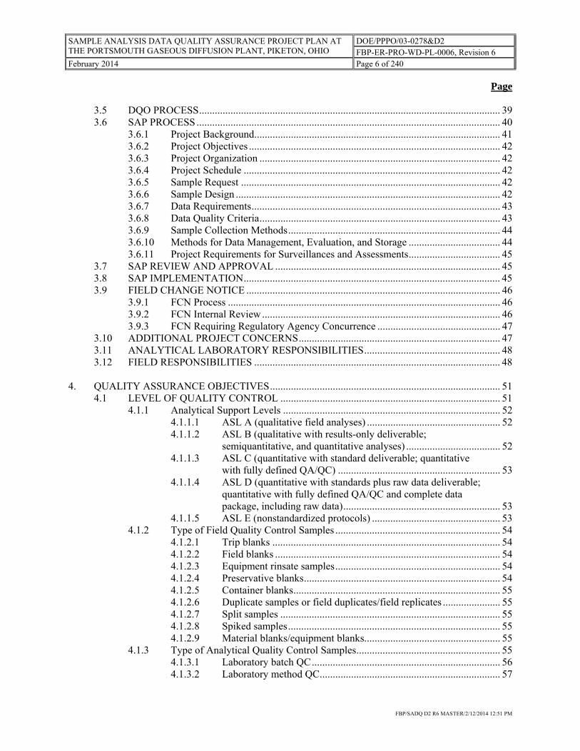
Page
3.5 DQO PROCESS ................................................................................................................... 39 3.6 SAP PROCESS .................................................................................................................... 40
3.6.1 Project Background .............................................................................................. 41 3.6.2 Project Objectives ................................................................................................ 42 3.6.3 Project Organization ............................................................................................ 42 3.6.4 Project Schedule .................................................................................................. 42 3.6.5 Sample Request ................................................................................................... 42 3.6.6 Sample Design ..................................................................................................... 42 3.6.7 Data Requirements ............................................................................................... 43 3.6.8 Data Quality Criteria ............................................................................................ 43 3.6.9 Sample Collection Methods ................................................................................. 44 3.6.10 Methods for Data Management, Evaluation, and Storage ................................... 44 3.6.11 Project Requirements for Surveillances and Assessments ................................... 45
3.7 SAP REVIEW AND APPROVAL ...................................................................................... 45 3.8 SAP IMPLEMENTATION .................................................................................................. 45 3.9 FIELD CHANGE NOTICE ................................................................................................. 46
3.9.1 FCN Process ........................................................................................................ 46 3.9.2 FCN Internal Review ........................................................................................... 46 3.9.3 FCN Requiring Regulatory Agency Concurrence ............................................... 47
3.10 ADDITIONAL PROJECT CONCERNS ............................................................................. 47 3.11 ANALYTICAL LABORATORY RESPONSIBILITIES .................................................... 48 3.12 FIELD RESPONSIBILITIES .............................................................................................. 48
4. QUALITY ASSURANCE OBJECTIVES ........................................................................................ 51
4.1 LEVEL OF QUALITY CONTROL .................................................................................... 51 4.1.1 Analytical Support Levels ................................................................................... 52
4.1.1.1 ASL A (qualitative field analyses) ................................................... 52 4.1.1.2 ASL B (qualitative with results-only deliverable;
semiquantitative, and quantitative analyses) .................................... 52 4.1.1.3 ASL C (quantitative with standard deliverable; quantitative
with fully defined QA/QC) .............................................................. 53 4.1.1.4 ASL D (quantitative with standards plus raw data deliverable;
quantitative with fully defined QA/QC and complete data package, including raw data) ............................................................ 53
4.1.1.5 ASL E (nonstandardized protocols) ................................................. 53 4.1.2 Type of Field Quality Control Samples ............................................................... 54
4.1.2.1 Trip blanks ....................................................................................... 54 4.1.2.2 Field blanks ...................................................................................... 54 4.1.2.3 Equipment rinsate samples ............................................................... 54 4.1.2.4 Preservative blanks ........................................................................... 54 4.1.2.5 Container blanks ............................................................................... 55 4.1.2.6 Duplicate samples or field duplicates/field replicates ...................... 55 4.1.2.7 Split samples .................................................................................... 55 4.1.2.8 Spiked samples ................................................................................. 55 4.1.2.9 Material blanks/equipment blanks.................................................... 55
4.1.3 Type of Analytical Quality Control Samples ....................................................... 55 4.1.3.1 Laboratory batch QC ........................................................................ 56 4.1.3.2 Laboratory method QC ..................................................................... 57

SAMPLE ANALYSIS DATA QUALITY ASSURANCE PROJECT PLAN AT THE PORTSMOUTH GASEOUS DIFFUSION PLANT, PIKETON, OHIO
DOE/PPPO/03-0278&D2 FBP-ER-PRO-WD-PL-0006, Revision 6
February 2014 Page 7 of 240
FBP/SADQ D2 R6 MASTER/2/12/2014 12:51 PM
Page
4.1.4 Additional Laboratory QC Samples ..................................................................... 58 4.1.4.1 Blind and double blind QC samples ................................................. 58 4.1.4.2 Performance evaluation samples ...................................................... 58
4.2 PRECISION, ACCURACY, REPRESENTATIVENESS, COMPLETENESS, AND COMPARABILITY (PARCC) PARAMETERS ....................................................... 58 4.2.1 Precision .............................................................................................................. 58 4.2.2 Accuracy .............................................................................................................. 58 4.2.3 Representativeness ............................................................................................... 59 4.2.4 Completeness ....................................................................................................... 59 4.2.5 Comparability ...................................................................................................... 59
4.3 QUALIFYING HISTORICAL DATA ................................................................................ 59 4.4 TRAINING, RECORDS ADMINISTRATION, AND DOCUMENT CONTROL ............ 60
4.4.1 Training and Qualification ................................................................................... 60 4.4.1.1 Site training and qualification .......................................................... 60 4.4.1.2 Job-specific training and qualification ............................................. 60 4.4.1.3 Implementation................................................................................. 60 4.4.1.4 Documentation ................................................................................. 61
4.4.2 Records Administration ....................................................................................... 61 4.4.2.1 Document request ............................................................................. 61 4.4.2.2 Document retention and disposition ................................................. 62 4.4.2.3 Document storage ............................................................................. 62 4.4.2.4 Record preparation ........................................................................... 63 4.4.2.5 Records control ................................................................................ 63 4.4.2.6 Off-site project files ......................................................................... 65
4.4.3 Document Control ................................................................................................ 65 4.4.3.1 Preparation, review, and approval of documents and drawings ....... 65 4.4.3.2 Changes to documents and drawings ............................................... 66 4.4.3.3 Document change requests ............................................................... 66
4.5 SADQ REVIEW AND REVISION ..................................................................................... 66 4.5.1 SADQ DCR Process ............................................................................................ 67 4.5.2 SADQ Distribution .............................................................................................. 68 4.5.3 Distribution of Revisions ..................................................................................... 68 4.5.4 Incorporation of Changes ..................................................................................... 68
4.6 COMPUTER HARDWARE AND SOFTWARE QUALITY ASSURANCE .................... 68 5. FIELD ACTIVITIES ........................................................................................................................ 71
5.1 RESPONSIBILITIES ........................................................................................................... 71 5.1.1 Project Manager ................................................................................................... 71 5.1.2 Geologist .............................................................................................................. 71 5.1.3 Field Team Leader ............................................................................................... 71 5.1.4 Field Activity Team Members ............................................................................. 71
5.2 FIELD DOCUMENTATION .............................................................................................. 72 5.2.1 Field Activity Log ................................................................................................ 73 5.2.2 Subsurface Borehole Log ..................................................................................... 73 5.2.3 Subsurface Borehole Abandonment Record ........................................................ 73 5.2.4 Well Completion Log .......................................................................................... 74 5.2.5 Monitoring Well Plugging and Abandonment Record ........................................ 75 5.2.6 Monitoring Well Development Form .................................................................. 75

SAMPLE ANALYSIS DATA QUALITY ASSURANCE PROJECT PLAN AT THE PORTSMOUTH GASEOUS DIFFUSION PLANT, PIKETON, OHIO
DOE/PPPO/03-0278&D2 FBP-ER-PRO-WD-PL-0006, Revision 6
February 2014 Page 8 of 240
FBP/SADQ D2 R6 MASTER/2/12/2014 12:51 PM
Page
5.3 FIELD ACTIVITY REQUIREMENTS ............................................................................... 75 5.3.1 Subsurface Sample Location Identifiers .............................................................. 76 5.3.2 General Drilling Practices .................................................................................... 76 5.3.3 Well Design and Construction ............................................................................. 77
5.3.3.1 Well construction materials .............................................................. 77 5.3.3.2 Well construction ............................................................................. 78 5.3.3.3 Minford Formation ........................................................................... 79 5.3.3.4 Gallia Formation .............................................................................. 79 5.3.3.5 Berea Formation ............................................................................... 79 5.3.3.6 Well at grade completion ................................................................. 80
5.3.4 Well Development ............................................................................................... 81 5.3.5 Well Maintenance ................................................................................................ 81
5.3.5.1 Well inspection ................................................................................. 82 5.3.5.2 Well inspection during sampling ...................................................... 82 5.3.5.3 Well inspection reporting ................................................................. 82
5.3.6 Well and Borehole Abandonment ........................................................................ 83 5.3.6.1 Hand-augered borehole abandonment .............................................. 83 5.3.6.2 Drilled boreholes abandonment ....................................................... 83 5.3.6.3 Direct-push borehole abandonment ................................................. 84 5.3.6.4 Well abandonment............................................................................ 84
5.3.7 Aquifer/Permeability Testing .............................................................................. 84 5.3.7.1 Slug tests .......................................................................................... 85 5.3.7.2 Aquifer tests ..................................................................................... 85
5.3.8 Dye Tracer Testing .............................................................................................. 86 5.3.9 Geophysical Surveys ............................................................................................ 87
5.3.9.1 Borehole geophysical logging .......................................................... 87 5.3.9.2 Surface geophysical surveys ............................................................ 88
5.3.10 Geotechnical Testing ........................................................................................... 88 5.3.11 Field Radiological Contamination Surveys ......................................................... 88 5.3.12 Special Field Activities ........................................................................................ 89
5.3.12.1 Nondestructive assay ........................................................................ 90 5.3.12.2 Field screening ................................................................................. 90
6. SAMPLING REQUIREMENTS....................................................................................................... 91
6.1 RESPONSIBILITIES ........................................................................................................... 91 6.1.1 Project Manager ................................................................................................... 91 6.1.2 Field Team Lead .................................................................................................. 91 6.1.3 Field Team Members ........................................................................................... 92
6.2 SAMPLE COLLECTION FORMS ..................................................................................... 92 6.2.1 Sample Collection Logging ................................................................................. 92 6.2.2 Groundwater Sample Collection Logging ........................................................... 93
6.3 SAMPLE NUMBER AND LOCATION IDENTIFIERS .................................................... 93 6.3.1 Routine Environmental Monitoring Sample Numbers ........................................ 93 6.3.2 Non-routine Environmental Sample Numbers ..................................................... 93 6.3.3 Containerized Waste Sample Numbers ............................................................... 94 6.3.4 Building Characterization Sample Numbers ....................................................... 94 6.3.5 Process Equipment Sample Numbers .................................................................. 94
6.4 SAMPLE CONTAINER PREPARATION ......................................................................... 95

SAMPLE ANALYSIS DATA QUALITY ASSURANCE PROJECT PLAN AT THE PORTSMOUTH GASEOUS DIFFUSION PLANT, PIKETON, OHIO
DOE/PPPO/03-0278&D2 FBP-ER-PRO-WD-PL-0006, Revision 6
February 2014 Page 9 of 240
FBP/SADQ D2 R6 MASTER/2/12/2014 12:51 PM
Page
6.5 SAMPLE CONTAINER PRESERVATION ....................................................................... 95 6.6 COLLECTION OF AQUEOUS SAMPLES........................................................................ 95
6.6.1 Field Analytical Requirements for Natural Water Samples ................................. 95 6.6.1.1 Temperature ..................................................................................... 96 6.6.1.2 pH ..................................................................................................... 96 6.6.1.3 Specific conductance ........................................................................ 96 6.6.1.4 Dissolved oxygen ............................................................................. 97 6.6.1.5 Oxidation-reduction potential .......................................................... 97 6.6.1.6 Turbidity ........................................................................................... 97
6.6.2 Groundwater Sampling ........................................................................................ 97 6.6.2.1 Water level measurements ............................................................... 98 6.6.2.2 General groundwater sampling requirements ................................... 98 6.6.2.3 Standard purging .............................................................................. 99 6.6.2.4 Low-flow purging .......................................................................... 100 6.6.2.5 Parameter-specific sampling requirements .................................... 100 6.6.2.6 Sampling groundwater from residential water supply and
other production wells .................................................................... 101 6.6.3 Surface Water Sampling .................................................................................... 102
6.6.3.1 Grab sampling ................................................................................ 102 6.6.3.2 Composite sampling ....................................................................... 102 6.6.3.3 Parameter-specific surface water sampling .................................... 102
6.6.4 Aqueous Sample Collection Completion ........................................................... 103 6.6.5 Wastewater Sampling ........................................................................................ 104
6.6.5.1 NPDES sampling............................................................................ 104 6.6.5.2 DOE-required effluent monitoring ................................................. 105
6.7 COLLECTION OF QC SAMPLES ................................................................................... 106 6.8 COLLECTION OF SOLID SAMPLES ............................................................................. 106
6.8.1 Surface Soil Sampling ....................................................................................... 107 6.8.2 Solid Sample Field Preparation ......................................................................... 108 6.8.3 Sediment Sampling ............................................................................................ 108 6.8.4 Subsurface Soil Sampling .................................................................................. 108 6.8.5 Building Material Sample Collection Requirements ......................................... 109
6.8.5.1 Metal coating and paint chip samples ............................................ 110 6.8.5.2 Wood samples ................................................................................ 110 6.8.5.3 Concrete/Masonry samples ............................................................ 110 6.8.5.4 Asphalt samples ............................................................................. 110 6.8.5.5 Shreddable samples ........................................................................ 110 6.8.5.6 Sheet metal ..................................................................................... 110 6.8.5.7 Structural steel ................................................................................ 110 6.8.5.8 Transite ........................................................................................... 110 6.8.5.9 Wipes .............................................................................................. 111
6.8.6 Process Equipment and Piping .......................................................................... 112 6.8.7 Waste Sampling ................................................................................................. 112
6.8.7.1 Containerized waste ....................................................................... 112 6.8.7.2 Sludge sampling ............................................................................. 114 6.8.7.3 Residue sampling ........................................................................... 114
6.9 AMBIENT AIR SAMPLES ............................................................................................... 114 6.9.1 Environmental Radiological Air Particulate Monitoring ................................... 114

SAMPLE ANALYSIS DATA QUALITY ASSURANCE PROJECT PLAN AT THE PORTSMOUTH GASEOUS DIFFUSION PLANT, PIKETON, OHIO
DOE/PPPO/03-0278&D2 FBP-ER-PRO-WD-PL-0006, Revision 6
February 2014 Page 10 of 240
FBP/SADQ D2 R6 MASTER/2/12/2014 12:51 PM
Page
6.9.2 Meteorological Monitoring Program ................................................................. 116 6.9.3 Monitoring for Airborne Contaminants in the Field .......................................... 117
6.9.3.1 General area air samples for worker protection ............................. 117 6.9.3.2 Monitoring for organic and inorganic contaminants in the field .... 117
6.10 BIOLOGICAL SAMPLING .............................................................................................. 119 6.10.1 Vegetation Sampling .......................................................................................... 120 6.10.2 Dairy Products ................................................................................................... 120 6.10.3 Fish Sampling .................................................................................................... 120 6.10.4 Deer Sampling ................................................................................................... 120
6.11 MISCELLANEOUS SAMPLES ....................................................................................... 120 6.11.1 Asbestos-containing Building Materials ............................................................ 121 6.11.2 PCB-contaminated Materials ............................................................................. 121 6.11.3 Radiation Monitoring ......................................................................................... 121 6.11.4 Sodium Iodide Detector ..................................................................................... 121 6.11.5 Radiological Survey Using an NaI Detector ...................................................... 122
6.12 DECONTAMINATION REQUIREMENTS ..................................................................... 122 6.12.1 Drilling Equipment Decontamination ................................................................ 123 6.12.2 Submersible Pumps ............................................................................................ 123 6.12.3 Water Level Measurement Equipment .............................................................. 123 6.12.4 Verification of Decontamination Effectiveness ................................................. 123
7. SAMPLE CUSTODY, HANDLING, AND SHIPPING................................................................. 125
7.1 FIELD SAMPLE CUSTODY REQUIREMENTS ............................................................ 126 7.1.1 Sample Tracking and Control Documentation .................................................. 126 7.1.2 Sample Identification and Labeling ................................................................... 127 7.1.3 Request for Analysis .......................................................................................... 127 7.1.4 Field Storage ...................................................................................................... 127
7.2 SAMPLE CLASSIFICATION, PACKAGING, AND SHIPMENT .................................. 128 7.2.1 Sample Classification ........................................................................................ 128
7.2.1.1 Environmental samples .................................................................. 128 7.2.1.2 Known, suspected, or routine hazardous substance samples ......... 128 7.2.1.3 Radioactive samples ....................................................................... 128
7.2.2 Sample Packaging .............................................................................................. 128 7.3 ANALYTICAL LABORATORY ...................................................................................... 130
7.3.1 Laboratory Sample Receipt, Examination, and Management ............................ 130 7.3.2 Change Request ................................................................................................. 131 7.3.3 Sample Holding and Disposition ....................................................................... 131 7.3.4 Laboratory Waste ............................................................................................... 131
8. CALIBRATION PROCEDURES AND FREQUENCY ................................................................ 133
8.1 RESPONSIBILITIES ......................................................................................................... 133 8.2 CALIBRATION PROCEDURES ...................................................................................... 133 8.3 CALIBRATION FREQUENCY ........................................................................................ 133 8.4 CALIBRATION DOCUMENTATION REQUIREMENTS ............................................. 133 8.5 EQUIPMENT FAILURE ................................................................................................... 134 8.6 CALIBRATION STANDARDS ........................................................................................ 134 8.7 FIELD EQUIPMENT CALIBRATION ............................................................................ 134
8.7.1 Environmental (High- and Low-volume) Air Monitoring Station Calibration .. 134

SAMPLE ANALYSIS DATA QUALITY ASSURANCE PROJECT PLAN AT THE PORTSMOUTH GASEOUS DIFFUSION PLANT, PIKETON, OHIO
DOE/PPPO/03-0278&D2 FBP-ER-PRO-WD-PL-0006, Revision 6
February 2014 Page 11 of 240
FBP/SADQ D2 R6 MASTER/2/12/2014 12:51 PM
Page
8.7.2 Water Quality Meter Calibration ....................................................................... 135 8.7.3 Water Level Indicator Verification .................................................................... 135 8.7.4 Thermometer Verification ................................................................................. 135 8.7.5 Pressure Transducer Verification ....................................................................... 135 8.7.6 Photoionization Detectors .................................................................................. 135 8.7.7 Hand-held Radiological Survey Instruments ..................................................... 135 8.7.8 Dye Tracer Instrumentation ............................................................................... 136 8.7.9 Miscellaneous Instrumentation .......................................................................... 136
8.8 ANALYTICAL LABORATORY EQUIPMENT CALIBRATION .................................. 136 8.8.1 Laboratory Equipment Calibration Schedules ................................................... 136 8.8.2 Laboratory Equipment Calibration Frequency .................................................. 136
9. INSPECTION/ACCEPTANCE OF SUPPLIES AND CONSUMABLES ..................................... 139
9.1 SAMPLE CONTAINERS .................................................................................................. 139 9.2 REAGENT-GRADE WATER ........................................................................................... 139 9.3 STANDARD SOLUTIONS AND MATERIALS ............................................................. 139
10. PREVENTIVE MAINTENANCE .................................................................................................. 141
10.1 PROGRAM DEVELOPMENT ......................................................................................... 141 10.2 RESPONSIBILITIES ......................................................................................................... 141
11. ANALYTICAL SERVICES ........................................................................................................... 143
11.1 FBP ANALYTICAL SERVICES APPROACH ................................................................ 143 11.2 RESPONSIBILITIES ......................................................................................................... 143 11.3 ANALYTICAL SUPPORT LEVELS ................................................................................ 144
12. INTERNAL QUALITY CONTROL CHECKS AND FREQUENCY ........................................... 145
12.1 QUALITY CONTROL CHECKS AND PROCEDURES ................................................. 145 12.2 FIELD QUALITY CONTROL .......................................................................................... 145
13. DATA MANAGEMENT AND REPORTING ............................................................................... 147 13.1 ROLE OF DATA MANAGEMENT ................................................................................. 147
13.1.1 Volume of Data .................................................................................................. 147 13.1.2 Compliance with Regulatory Controls............................................................... 147 13.1.3 Flexible and Timely Response to Data Queries ................................................. 147
13.2 DATA LIFE CYCLE ......................................................................................................... 148 13.2.1 Planning ............................................................................................................. 148 13.2.2 Collection of Samples ........................................................................................ 148 13.2.3 Transfer and Handling of Samples .................................................................... 149 13.2.4 Laboratory Analysis and Reporting ................................................................... 149 13.2.5 Completeness Verification ................................................................................. 149 13.2.6 Data Validation .................................................................................................. 149 13.2.7 Data Reduction .................................................................................................. 150 13.2.8 Data Analysis Reports ....................................................................................... 150 13.2.9 Records Management ........................................................................................ 150 13.2.10 Data Archiving and Storage ............................................................................... 150
13.3 DATA MANAGEMENT SYSTEM .................................................................................. 150 13.3.1 Project Environmental Measurements System .................................................. 151
SAMPLE ANALYSIS DATA QUALITY ASSURANCE PROJECT PLAN AT THE PORTSMOUTH GASEOUS DIFFUSION PLANT, PIKETON, OHIO
DOE/PPPO/03-0278&D2 FBP-ER-PRO-WD-PL-0006, Revision 6
February 2014 Page 12 of 240
FBP/SADQ D2 R6 MASTER/2/12/2014 12:51 PM
Page
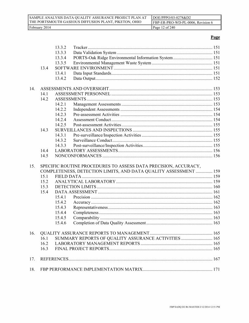
13.3.2 Tracker ............................................................................................................... 151 13.3.3 Data Validation System ..................................................................................... 151 13.3.4 PORTS-Oak Ridge Environmental Information System ................................... 151 13.3.5 Environmental Management Waste System ...................................................... 151
13.4 SOFTWARE ENVIRONMENT ........................................................................................ 151 13.4.1 Data Input Standards .......................................................................................... 151 13.4.2 Data Output ........................................................................................................ 152
14. ASSESSMENTS AND OVERSIGHT ............................................................................................ 153
14.1 ASSESSMENT PERSONNEL .......................................................................................... 153 14.2 ASSESSMENTS ................................................................................................................ 153
14.2.1 Management Assessments ................................................................................. 153 14.2.2 Independent Assessments .................................................................................. 154 14.2.3 Pre-assessment Activities .................................................................................. 154 14.2.4 Assessment Conduct .......................................................................................... 154 14.2.5 Post-assessment Activities ................................................................................. 155
14.3 SURVEILLANCES AND INSPECTIONS ....................................................................... 155 14.3.1 Pre-surveillance/Inspection Activities ............................................................... 155 14.3.2 Surveillance Conduct ......................................................................................... 155 14.3.3 Post-surveillance/Inspection Activities .............................................................. 155
14.4 LABORATORY ASSESSMENTS .................................................................................... 156 14.5 NONCONFORMANCES .................................................................................................. 156
15. SPECIFIC ROUTINE PROCEDURES TO ASSESS DATA PRECISION, ACCURACY,
COMPLETENESS, DETECTION LIMITS, AND DATA QUALITY ASSESSMENT ............... 159 15.1 FIELD DATA .................................................................................................................... 159 15.2 ANALYTICAL LABORATORY ...................................................................................... 159 15.3 DETECTION LIMITS ....................................................................................................... 160 15.4 DATA ASSESSMENT ...................................................................................................... 161
15.4.1 Precision ............................................................................................................ 162 15.4.2 Accuracy ............................................................................................................ 162 15.4.3 Representativeness ............................................................................................. 163 15.4.4 Completeness ..................................................................................................... 163 15.4.5 Comparability .................................................................................................... 163 15.4.6 Completion of Data Quality Assessment ........................................................... 163
16. QUALITY ASSURANCE REPORTS TO MANAGEMENT ........................................................ 165
16.1 SUMMARY REPORTS OF QUALITY ASSURANCE ACTIVITIES ............................ 165 16.2 LABORATORY MANAGEMENT REPORTS ................................................................ 165 16.3 FINAL PROJECT REPORTS ............................................................................................ 165
17. REFERENCES ................................................................................................................................ 167 18. FBP PERFORMANCE IMPLEMENTATION MATRIX .............................................................. 171

SAMPLE ANALYSIS DATA QUALITY ASSURANCE PROJECT PLAN AT THE PORTSMOUTH GASEOUS DIFFUSION PLANT, PIKETON, OHIO
DOE/PPPO/03-0278&D2 FBP-ER-PRO-WD-PL-0006, Revision 6
February 2014 Page 13 of 240
FBP/SADQ D2 R6 MASTER/2/12/2014 12:51 PM
Page APPENDIX A: FIGURES, TABLES, AND FORMS .............................................................................. 177 APPENDIX B: DATA QUALITY OBJECTIVES ................................................................................... 197 APPENDIX C: DATA VALIDATION .................................................................................................... 213

SAMPLE ANALYSIS DATA QUALITY ASSURANCE PROJECT PLAN AT THE PORTSMOUTH GASEOUS DIFFUSION PLANT, PIKETON, OHIO
DOE/PPPO/03-0278&D2 FBP-ER-PRO-WD-PL-0006, Revision 6
February 2014 Page 14 of 240
FBP/SADQ D2 R6 MASTER/2/12/2014 12:51 PM
This page is intentionally left blank.

SAMPLE ANALYSIS DATA QUALITY ASSURANCE PROJECT PLAN AT THE PORTSMOUTH GASEOUS DIFFUSION PLANT, PIKETON, OHIO
DOE/PPPO/03-0278&D2 FBP-ER-PRO-WD-PL-0006, Revision 6
February 2014 Page 15 of 240
FBP/SADQ D2 R6 MASTER/2/12/2014 12:51 PM
ACRONYMS ACM asbestos-containing material ACO Administrative Consent Order AEA Atomic Energy Act ANSI American National Standards Institute APM analytical project manager ARAR applicable or relevant and appropriate requirement ASL analytical support level ASTM American Society for Testing and Materials bgs below ground surface BJC Bechtel Jacobs Company LLC CAA Clean Air Act CAM continuous air monitor CERCLA Comprehensive Environmental Response, Compensation, and Liability Act of 1980, as
amended CFR Code of Federal Regulations CIT colorimetric indicator tube CMI Corrective Measures Implementation CMS corrective measures study COC chain-of-custody COLIWASA composite liquid waste sampler CRDL contract-required detection limit CWA Clean Water Act D&D decontamination and decommissioning DCR document change request DFF&O The April 13, 2010 Director’s Final Findings and Orders for Removal Action and
Remedial Investigation and Feasibility Study and Remedial Design and Remedial Action, including the July 16, 2012 Modification thereto
DNAPL dense non-aqueous phase liquid DO dissolved oxygen DOE U.S. Department of Energy DOECAP Department of Energy Consolidated Audit Program DOT U.S. Department of Transportation DQA data quality assessment DQO data quality objective DV data validation EDD electronic data deliverable eMWaste® Environmental Management Waste System EPA U.S. Environmental Protection Agency FBP Fluor-B&W Portsmouth LLC FCN field change notice FID flame-ionization detector FIDLER field instrument for the detection of low-energy radiation FV field validation GPS global positioning system ID identification ISMS Integrated Safety Management System LCS laboratory control sample LNAPL light non-aqueous phase liquid

SAMPLE ANALYSIS DATA QUALITY ASSURANCE PROJECT PLAN AT THE PORTSMOUTH GASEOUS DIFFUSION PLANT, PIKETON, OHIO
DOE/PPPO/03-0278&D2 FBP-ER-PRO-WD-PL-0006, Revision 6
February 2014 Page 16 of 240
FBP/SADQ D2 R6 MASTER/2/12/2014 12:51 PM
MDC minimum detectable concentration MDL method detection limit MQO measurement quality objective MS matrix spike MSD matrix spike duplicate NAPL non-aqueous phase liquid NDA nondestructive assay NESHAP National Emissions Standards for Hazardous Air Pollutants NIST National Institute of Standards and Technology NPDES National Pollutant Discharge Elimination System NRC U.S. Nuclear Regulatory Commission OAC Ohio Administrative Code Ohio EPA Ohio Environmental Protection Agency OREIS Oak Ridge Environmental Information System ORP oxidation reduction potential OSDC on-site disposal cell OSHA Occupational Safety and Health Administration PARCC precision, accuracy, representativeness, completeness, and comparability PCB polychlorinated biphenyl PEMS Project Environmental Measurements System PID photoionization detector PORTS Portsmouth Gaseous Diffusion Plant PVC polyvinyl chloride QA quality assurance QAPD Quality Assurance Program Description (QAPD) QAPP Quality Assurance Project Plan QC quality control QSAS Quality Systems for Analytical Services RA response action RCRA Resource Conservation and Recovery Act of 1976, as amended RD remedial design RDL required detection limit RER relative error ratio RFI RCRA facility investigation RI/FS Remedial Investigation/Feasibility Study RMDC Records Management/Document Control RPD relative percent difference SADQ Sample Data Analysis Data Quality Assurance Project Plan SAP sampling and analysis plan SDWA Safe Drinking Water Act SME subject matter expert SMO Sample Management Office SOW statement of work SR sampling request SQA software quality assurance SVOC semivolatile organic compound TLD thermoluminescent dosimeter TOX total organic halogens TSCA Toxic Substances Control Act USEC United States Enrichment Corporation

SAMPLE ANALYSIS DATA QUALITY ASSURANCE PROJECT PLAN AT THE PORTSMOUTH GASEOUS DIFFUSION PLANT, PIKETON, OHIO
DOE/PPPO/03-0278&D2 FBP-ER-PRO-WD-PL-0006, Revision 6
February 2014 Page 17 of 240
FBP/SADQ D2 R6 MASTER/2/12/2014 12:51 PM
VOC volatile organic compound VSL validation support level VSP Visual Sample Plan WCT waste container tracking
SAMPLE ANALYSIS DATA QUALITY ASSURANCE PROJECT PLAN AT THE PORTSMOUTH GASEOUS DIFFUSION PLANT, PIKETON, OHIO
DOE/PPPO/03-0278&D2 FBP-ER-PRO-WD-PL-0006, Revision 6
February 2014 Page 18 of 240
FBP/SADQ D2 R6 MASTER/2/12/2014 12:51 PM
This page is intentionally left blank.

SAMPLE ANALYSIS DATA QUALITY ASSURANCE PROJECT PLAN AT THE PORTSMOUTH GASEOUS DIFFUSION PLANT, PIKETON, OHIO
DOE/PPPO/03-0278&D2 FBP-ER-PRO-WD-PL-0006, Revision 6
February 2014 Page 19 of 240
FBP/SADQ D2 R6 MASTER/2/12/2014 12:51 PM
1. INTRODUCTION This programmatic Sampling Analysis Data Quality Assurance Project Plan (SADQ) is one of three documents that comprise a Quality Assurance Project Plan (QAPP). When this SADQ is combined with project-specific sampling and analysis plans (SAPs) and their respective data quality objectives (DQOs), the combination is considered to be the QAPP. While the DQOs and SAPs are specific to discrete projects, this SADQ provides an overarching framework to ensure that standardized and consistent processes are utilized to obtain samples, perform data collection, and perform laboratory services. The goal of this SADQ is to streamline the systematic planning process and provide uniformity to the above mentioned processes. This document was written to address elements of data collection that do not materially change from project to project and presents the organization, objective, functional activities, and specific quality assurance/quality control (QA/QC) activities associated with the programs at the Portsmouth Gaseous Diffusion Plant (PORTS). The variable project requirements for sampling, sample handling and storage, chain-of-custody (COC) records, and discrete laboratory/field analyses are to be specified in the project-specific DQOs and SAPs. The SADQ for PORTS is developed to fulfill sampling and data quality requirements for decontamination and decommissioning (D&D) under The April 13, 2010 Director’s Final Findings and Orders for Removal Action and Remedial Investigation and Feasibility Study and Remedial Design and Remedial Action, including the July 16, 2012 Modification thereto (referred to as the D&D DFF&O) (Ohio Environmental Protection Agency [Ohio EPA] 2012), and for environmental cleanup under the Ohio Consent Decree and U.S. Environmental Protection Agency (EPA) Administrative Consent Order (ACO), among other sampling and data quality requirements. This document is developed to address quality requirements specified in multiple regulatory program areas and U.S. Department of Energy (DOE) policies and Orders. It is designed to ensure that data collected under the Resource Conservation and Recovery Act of 1976, as amended (RCRA), the Comprehensive Environmental Response, Compensation and Liability Act of 1980, as amended (CERCLA), DOE Orders, or other applicable requirements identified during project scoping, is usable in decision-making at PORTS. Specific data quality requirements will be established on a project-by-project basis for each project which is subject to this SADQ. This programmatic SADQ provides a basis for development of future project-specific SAPs. These data requirements will be evaluated and presented in each project SAP’s DQOs. This section summarizes the regulatory history of PORTS as context for the sampling data analysis activities that are performed under this SADQ. 1.1 PORTS REGULATORY HISTORY Dating back to 1989, nine major environmental regulatory documents have been established for PORTS along with amendments to two of these agreements. These are summarized in Table 1.1. The table identifies the document, its year of enactment, and its major intended purpose. Environmental remediation including the cleanup of soil, groundwater and other environmental media contaminated by PORTS operations, is conducted in accordance with the EPA ACO, issued on September 29, 1989 (amended in 1994 and 1997), and the Consent Decree with the State of Ohio, issued on August 29, 1989. EPA and Ohio EPA oversee environmental remediation activities at PORTS under the RCRA Corrective Action Program and CERCLA Program.

SAMPLE ANALYSIS DATA QUALITY ASSURANCE PROJECT PLAN AT THE PORTSMOUTH GASEOUS DIFFUSION PLANT, PIKETON, OHIO
DOE/PPPO/03-0278&D2 FBP-ER-PRO-WD-PL-0006, Revision 6
February 2014 Page 20 of 240
FBP/SADQ D2 R6 MASTER/2/12/2014 12:51 PM
Table 1.1. PORTS Regulatory Documents
Regulatory Document Date Purpose Ohio EPA Consent Decree 1989 Requires investigation and remediation of solid
and hazardous waste units in accordance with RCRA, between Ohio EPA and DOE.
Toxic Substances Control Act Compliance Agreement (EPA and DOE)
1992 Brings DOE into compliance with TSCA regulations; and establishes D&D milestones for TSCA waste, as modified in 1997.
Ohio Hazardous Waste Facility Installation and Operation Permit (and Renewal)
1995-present Allows RCRA permitted container storage for hazardous waste with DOE as the Owner and Co-Operator and current Co-Operator; references the RCRA Corrective Action Orders: Ohio Consent, Administrative Consent Order, and Ohio Director’s Final Findings and Orders for Integration; and amended in 2011 to add/remove Co-operator.
Ohio Director’s Final Findings and Orders for Site Treatment Plan
1995 Allows for the storage of mixed hazardous waste beyond the 1-year regulatory limit; requires an Annual Site Treatment Plan Report; and the 1993 amendment was superseded.
Administrative Consent Order 1997 Requires investigation and remediation of solid and hazardous waste units in accordance with RCRA and CERCLA, between EPA and DOE.
Ohio Director’s Final Findings and Orders for Integration
1999 Integrates five RCRA closures into the RCRA Corrective Action Program. Provided for integration of groundwater monitoring and surveillance; maintenance of RCRA and solid waste units; amended in 2011 to update regulatory citations; and include the D&D contractor.
Ohio Director’s Final Findings and Orders [for Depleted Uranium Hexafluoride]
2008 Parties bound to these Orders are required to submit to Ohio EPA a DUF6 Cylinder Management Plan and implement the approved plan.
Modification of Director’s Final Findings and Orders of February 22, 2008
2011 Parties bound to these Orders are required to submit to Ohio EPA a DUF6 Cylinder Management Plan and implement the approved plan.
Ohio Director’s Final Findings and Orders [for Depleted Uranium Hexafluoride]
2013 Parties bound to this Order are required to submit to Ohio EPA a modified DUF6 Cylinder Management Plan and fund two specified supplemental environmental projects.
Ohio Director’s Final Findings and Orders for Removal Action and Remedial Investigation and Feasibility Study and Remedial Design and Remedial Action [for the Portsmouth Gaseous Diffusion Plant (Decontamination and Decommissioning Project)]
2010 Provides the framework for DOE to address the D&D of the GDP and support facilities using the framework of the CERCLA process; amended in 2011 with revisions to Attachments G, H, and J, corrected inadvertent omissions, reflected current strategy of documentation; and amended in 2012 with a revision to Attachment H.
CERCLA = Comprehensive Environmental Response, Compensation, and Liability Act of 1980 (as amended) D&D = decontamination and decommissioning DOE = U.S. Department of Energy DUF6 = depleted uranium hexafluoride
EPA = U.S. Environmental Protection Agency GDP = gaseous diffusion plant Ohio EPA = Ohio Environmental Protection Agency RCRA = Resource Conservation and Recovery Act, as amended TSCA = Toxic Substances Control Act of 1976

SAMPLE ANALYSIS DATA QUALITY ASSURANCE PROJECT PLAN AT THE PORTSMOUTH GASEOUS DIFFUSION PLANT, PIKETON, OHIO
DOE/PPPO/03-0278&D2 FBP-ER-PRO-WD-PL-0006, Revision 6
February 2014 Page 21 of 240
FBP/SADQ D2 R6 MASTER/2/12/2014 12:51 PM
Coincident with the Ohio Consent Decree, DOE established the Environmental Restoration Program in 1989 to identify, control, and remediate environmental contamination at PORTS. The Environmental Restoration Program addresses contaminated soil and groundwater associated with waste units pursuant to the Ohio Consent Decree, so long as DOE has obligations for those units under the Consent Decree. The RCRA facility investigations (RFIs) divided the facility into quadrants which roughly correspond to distinct groundwater flow directions within the primary water-bearing unit beneath PORTS, as well as surface water flow directions. This facilitated investigation, study, and implementation of corrective actions in a phased approach at PORTS. The Environmental Restoration Program was established to fulfill the clean-up requirements of the Ohio Consent Decree and the Amended EPA Consent Order (known as the “Three Party Order”) signed in June 1997. In the late 1990s, DOE completed the description of current environmental conditions, RFIs, and a clean-up alternatives study/corrective measures study (CMS) for each quadrant. These investigations and reports have detailed the characteristics of PORTS that are pertinent to the waste disposition evaluation and the nature and extent of contamination at PORTS. The primary sources of information include the RFIs for the four quadrants (DOE 1996a, 1996b, 1996c, 1996d) and the corresponding CMSs (DOE 1998a, 1998b, 2000, 2001). As a result of these studies, corrective measures and interim remedial measures, collectively called corrective actions, have been implemented at PORTS both within the operating plant area and in the buffer areas outside Perimeter Road to address threats posed to human health and the environment. Full investigation and corrective actions at process buildings and other process support buildings were deferred to D&D. On April 13, 2010, Ohio EPA issued the D&D DFF&O, which is an enforceable agreement between Ohio EPA and DOE that governs the process for D&D of the gaseous diffusion process buildings and associated facilities that are no longer in use at PORTS. This agreement, which applies to the D&D of buildings down to and including the building slab and disposal of wastes generated by D&D, uses the CERCLA framework for determining appropriate response actions. 1.2 SADQ OVERVIEW 1.2.1 SADQ Purpose The programmatic SADQ is one of three documents that comprise a QAPP. When this SADQ is combined with project-specific SAPs and their respective DQOs, the combination is considered to be the QAPP. The goal of this SADQ is to streamline the systematic planning process and provide uniformity to the above-mentioned processes. This programmatic document provides standards of performance for work control documents and sampling and analytical plans that are consistent with EPA QA/QC documents and the site Integrated Safety Management System (ISMS). The implementation of a quality-imposed process will reduce the cost through quality-proposed sampling events and analytical processes. This document provides guidance for field sampling, analytical activities, analytical requirements (Department of Energy Consolidated Audit Program [DOECAP] Quality Systems for Analytical Services [QSAS]), and associated data management and data quality to ensure the delivery of data that meets the requirements of the appropriate project specific and program requirements as defined in program-specific DQOs. This plan applies to all SAPs and sampling requests (SRs) developed pursuant to work plans, reports, etc. which are submitted under Orders, Agreements, and permits identified in Table 1.1 and associated requirements identified in Section 1.2.2.3, which are approved following approval of the SADQ. SAPs and SRs approved prior to the SADQ will come under the SADQ when said SAP or SR requires revision; at that time, requirements of any QAPP which is referenced in a SAP or SR will be replaced by the requirements of this SADQ and the applicable DQO and SAP.

SAMPLE ANALYSIS DATA QUALITY ASSURANCE PROJECT PLAN AT THE PORTSMOUTH GASEOUS DIFFUSION PLANT, PIKETON, OHIO
DOE/PPPO/03-0278&D2 FBP-ER-PRO-WD-PL-0006, Revision 6
February 2014 Page 22 of 240
FBP/SADQ D2 R6 MASTER/2/12/2014 12:51 PM
The SADQ was developed for sampling and analysis with a twofold purpose: (1) establish minimum standards of performance for operational and analytical activities, and (2) ensure that those standards are followed by all programs covered by the plan. Various aspects of remedial alternative and corrective action evaluations will rely on sampling data that will be used by decision makers under the D&D DFF&O, Ohio Consent Decree and/or EPA ACO. Collection, analysis, and management of the data that result from environmental and waste characterization samples are integral parts of the fulfillment of the Portsmouth cleanup mission. These activities must be executed under a quality program that ensures compliance with applicable regulations. A sample may be capable of providing data for a number of activities that are designed to accomplish the overall mission; these activities include investigation, characterization, restoration, waste management, and ensuring regulatory compliance. Therefore, it is necessary that sampling and analysis be conducted to provide usable, valid data of known quality, so that it can be used for decision making. The SADQ was also developed to identify requirements for sampling and analysis activities, which support compliance determinations, including but not limited to waste disposal criteria for on- and off-site disposition, waste shipping requirements, and support investigations and response actions under both the Ohio Consent Decree and D&D DFF&O. To this end, ongoing and future projects shall comply with QA/QC requirements specified herein. 1.2.2 SADQ Scope This programmatic plan consolidates the QA requirements specified in the Ohio Consent Decree, the EPA ACO, the Director’s Final Findings and Order for Integration, the D&D DFF&O, and the National Pollutant Discharge Elimination System (NPDES) Permit and any other environmental permits issued to DOE or the contractor. This plan applies to all SAPs and SRs developed pursuant to work plans, reports, etc. which are submitted under Orders, Agreements, and permits and also applies to SAPs and SRs developed to generate data necessary to fulfill CERCLA 120(h) land transfer requirements, as well as data requirements necessary to comply with all environmental laws and regulations, legal agreements, and permits applicable to PORTS. The Ohio EPA approval/concurrence process is the regulatory mechanism that ensures compliance with these requirements. These consolidated QA requirements are integrated into applicable sampling activities, consistent with EPA recommendations to consolidate QA requirements and documents whenever possible (EPA 1989). This programmatic plan is designed to ensure that work performed for environmental and waste characterization sampling programs and supporting activities are of adequate quality to fulfill project-specific DQOs and SAPs. The organization, objectives, functional activities, and specific QA/QC activities associated with implementation of the Ohio Consent Decree and the D&D DFF&O are presented in the SADQ. Basic requirements for sampling, sample handling and storage, COC records, and laboratory and field analyses are specified in the sections of this plan. The project-specific sampling and analytical requirements are to be specified in the project-specific SAPs. 1.2.2.1 D&D DFF&O requirements The D&D DFF&O includes requirements for preparation of multiple types of documents to conduct D&D at PORTS and requires each of these documents to address QA and QC for the processes within the document’s scope. Requirements are specified in the guidance referenced in the D&D DFF&O, which discusses the development of the documents and the generic statements of work (SOWs).

SAMPLE ANALYSIS DATA QUALITY ASSURANCE PROJECT PLAN AT THE PORTSMOUTH GASEOUS DIFFUSION PLANT, PIKETON, OHIO
DOE/PPPO/03-0278&D2 FBP-ER-PRO-WD-PL-0006, Revision 6
February 2014 Page 23 of 240
FBP/SADQ D2 R6 MASTER/2/12/2014 12:51 PM
The list below identifies the types of high-level documents to which the D&D DFF&O applies: Remedial Investigation/Feasibility Study (RI/FS) for the Site-Wide Waste Disposition Evaluation
Project and for the Process Building and Complex Facilities D&D Evaluation Project, including evaluation of risk as required by applicable guidance
Engineering Evaluation/Cost Analysis, including evaluation of risk as required by applicable
guidance Remedial Designs (RDs) Removal Action Work Plans Remedial Action Work Plans. Development of these documents necessitates development of additional deliverables, including plans, statements of work, and standard operating procedures. 1.2.2.2 Requirements of the Ohio Consent Decree, Ohio EPA Integration Orders, and
EPA Administrative Consent Order Each of these related legal agreements includes requirements for preparation of multiple types of documents to conduct investigation, cleanup of environmental contamination, and monitoring of environmental conditions. These agreements require remedial documents to address QA and QC for the processes within the document’s scope. Requirements are specified in the guidance referenced in the agreements, which discusses the development of the documents and the generic SOW. Examples of applicable projects and documents follow: Solid Waste Management Units
o RFI/CMS Work Plans o RFI/CMS Reports o Corrective Measures Implementation (CMI) Program Plans o CMI Reports o Interim Remedial Measures Work Plans.
Groundwater Monitoring Plans Corrective Measures Operation and Maintenance Plans. 1.2.2.3 Associated requirements In addition to compliance with the Ohio Consent Decree, EPA ACO, and the D&D DFF&O, PORTS must comply with DOE Orders and other regulatory requirements. Federal and state regulatory requirements and guidance applicable to PORTS include, but are not limited to, the following: CERCLA 120(h) land transfer requirements Clean Air Act (CAA) monitoring, including monitoring for National Emissions Standards for
Hazardous Air Pollutants (NESHAP) compliance. Stack monitoring is conducted under the CAA and to fulfill requirements of DOE Order 458.1 and DOE Order 435.1. The main areas affected by these regulations include certain elements of site RCRA corrective actions (e.g., stacks at treatment units)

SAMPLE ANALYSIS DATA QUALITY ASSURANCE PROJECT PLAN AT THE PORTSMOUTH GASEOUS DIFFUSION PLANT, PIKETON, OHIO
DOE/PPPO/03-0278&D2 FBP-ER-PRO-WD-PL-0006, Revision 6
February 2014 Page 24 of 240
FBP/SADQ D2 R6 MASTER/2/12/2014 12:51 PM
and landlord activities. These requirements include Ohio EPA rules and permits issued pursuant to CAA requirements.
Clean Water Act (CWA). Water discharges from PORTS fall under CWA (via the Fluor-B&W
Portsmouth LLC [FBP] Ohio NPDES permits), DOE Order 458.1, and DOE Order 231.1B. These requirements include Ohio EPA rules and permits issued pursuant to CWA requirements. Wastewater discharges shall be maintained within limits specified in the PORTS Ohio NPDES permit.
Safe Drinking Water Act (SDWA), and Ohio EPA rules and permits issued pursuant to SDWA
requirements National Environmental Policy Act National Historical Preservation Act RCRA Toxic Substances Control Act (TSCA) and associated Federal Facilities Compliance Agreement Pollution Prevention Act of 1990 DOE Orders 458.1, Chg 3, Radiation Protection of the Public and the Environment, and 435.1,
Radioactive Waste Management DOE Order 231.1B, Admin Chg 1, Environment, Safety and Health Reporting Data Quality Assessment: A Reviewer’s Guide (EPA 2006a) Guidance for Preparing Standard Operating Procedures (EPA 2001a) Guidance on Environmental Data Verification and Data Validation (EPA 2002a) Guidelines and Specifications for Preparing Quality Assurance Project Plans (Ohio EPA 1998) Laboratory and Field Screening Data Review (Ohio EPA 2005) Preparation Aids for the Development of Category 1 Quality Assurance Project Plans (EPA 1991) Quality Assurance/Quality Control Guidance for Removal Activities: Sampling QA/QC Plan and
Data Validation Procedures (EPA 1990). 1.2.2.4 Environmental requirements As noted in the scope section of this SADQ, activities that are driven by requirements specified in the D&D DFF&O, the Ohio Consent Decree, EPA ACO, and CERCLA 120(h) land transfer requirements, as well as data requirements necessary to comply with all environmental laws and regulations applicable to DOE PORTS, are covered under this SADQ. Activities conducted under the programs noted above require collection and analysis of samples under SADQ criteria. These criteria include, but are not limited to, the following:

SAMPLE ANALYSIS DATA QUALITY ASSURANCE PROJECT PLAN AT THE PORTSMOUTH GASEOUS DIFFUSION PLANT, PIKETON, OHIO
DOE/PPPO/03-0278&D2 FBP-ER-PRO-WD-PL-0006, Revision 6
February 2014 Page 25 of 240
FBP/SADQ D2 R6 MASTER/2/12/2014 12:51 PM
Characterization sampling of soil, groundwater, ponds, streams, sediments, underground storage tanks, etc., for evaluation of cleanup requirements
Geotechnical tests conducted on soils, sludge, and rock for treatability studies or engineering design
purposes Compliance sampling to determine compliance with permits and regulatory requirements, including
NPDES permits, RCRA Part B permit, Title V air pollution control permit, and all plans and requirements contained within those permits
Characterization sampling of structures and equipment for evaluation of response actions Characterization sampling of wastes for evaluation of treatment, handling, storage, transportation, and
disposal requirements Design sampling for structures, soils, groundwater to evaluate RD requirements Excavation control sampling to refine soil excavation volumes Confirmation and certification sampling to ensure cleanup standards have been achieved. 1.2.3 SADQ Development QA/QC requirements in this plan were developed in accordance with applicable EPA guidelines, DOE Orders, QA/QC documents referenced in the D&D DFF&O, professional technical standards, regulatory requirements, and specific project goals and requirements. The following documents were considered: EPA Guidance for Quality Assurance Project Plans (EPA 2001b) Superfund Remedial Design and Remedial Action Guidance (EPA 1986) DOE Order 414.1D, Quality Assurance Title 10, Code of Federal Regulations (CFR), Part 830.120 (10 CFR 830.120), “Quality Assurance
Requirements” DOE Order 241.1B, Scientific and Technical Information Management DOE Order 224.2A, Auditing of Programs and Operations Guidance for Data Useability in Risk Assessment, April 1992 (EPA 1992a) EPA Guidance on Systematic Planning Using the Data Quality Objectives Process (EPA 2006b) EPA Requirements for Quality Management Plans, Final (EPA 2001c) Guidance for Conducting RI/FS Under CERCLA (EPA 1988) Ohio EPA Division of Environmental Response and Revitalization Guidelines and Specifications for
Preparing QAPPs, September 1, 1998 - Final

SAMPLE ANALYSIS DATA QUALITY ASSURANCE PROJECT PLAN AT THE PORTSMOUTH GASEOUS DIFFUSION PLANT, PIKETON, OHIO
DOE/PPPO/03-0278&D2 FBP-ER-PRO-WD-PL-0006, Revision 6
February 2014 Page 26 of 240
FBP/SADQ D2 R6 MASTER/2/12/2014 12:51 PM
FBP-QA-PDD-00001, Quality Assurance Program Description (QAPD) (FBP 2012) Data Quality Assessment: A Reviewer’s Guide (EPA 2006a) Guidance for Preparing Standard Operating Procedures (EPA 2001a) Guidance on Environmental Data Verification and Data Validation (EPA 2002a) Guidelines and Specifications for Preparing Quality Assurance Project Plans (Ohio EPA 1998) Laboratory and Field Screening Data Review (Ohio EPA 2005) Preparation Aids for the Development of Category 1 Quality Assurance Project Plans (EPA 1991) Quality Assurance/Quality Control Guidance for Removal Activities: Sampling QA/QC Plan and
Data Validation Procedures (EPA 1990) EPA Guidance for Quality Assurance Project Plans for Modeling (EPA 2002b) Technical Guidance Document: Construction Quality Assurance and Quality Control for Waste
Containment Facilities (EPA 1993) Multi-Agency Radiation Survey and Site Investigation Manual (also known as MARSSIM)
(DOE et al. 2000) Multi-Agency Radiological Laboratory Analytical Protocols Manual (also known as MARLAP)
(U.S. Nuclear Regulatory Commission [NRC] 2004) Multi-Agency Radiation Survey and Assessment of Materials and Equipment Manual (also known as
MARSAME) (DOE et al. 2009). The SADQ provides for document changes in response to evolving program needs as new projects are implemented. This plan is intended to be a dynamic document in that it meets current site needs while retaining the flexibility to respond to advances in analytical methods, field techniques, operating procedures, and changes in the PORTS mission. 1.2.4 Use of the SADQ This programmatic SADQ is one of three documents that comprise a QAPP. When this SADQ is combined with project-specific SAPs and their respective DQOs, the combination is considered to be the QAPP. While the DQOs and SAPs are specific to discrete projects, this SADQ provides an overarching framework to ensure that standardized and consistent processes are utilized to obtain samples, perform data collection, and perform laboratory services. The goal of this SADQ is to streamline the systematic planning process and provide uniformity to the above-mentioned processes. This document was written to address elements of data collection that do not materially change from project to project and present the organization, objectives, functional activities, and specific QA/QC activities associated with the programs at PORTS. The variable project requirements for sampling, sample handling and storage, COC records, and discrete laboratory/field analyses are to be specified in the project-specific DQOs and SAPs. The SADQ comprises the requirements for planning, implementation of plans, and assessment of activities so that it may be used like a QA project plan as defined by EPA (EPA 2001b), except that it

SAMPLE ANALYSIS DATA QUALITY ASSURANCE PROJECT PLAN AT THE PORTSMOUTH GASEOUS DIFFUSION PLANT, PIKETON, OHIO
DOE/PPPO/03-0278&D2 FBP-ER-PRO-WD-PL-0006, Revision 6
February 2014 Page 27 of 240
FBP/SADQ D2 R6 MASTER/2/12/2014 12:51 PM
does not include portions that refer to project-specific samples. Project-specific samples are addressed by the DQO/SAP process, which are designed to provide project-specific planning; overall guidance for sampling and discrete laboratory analysis; and QA/QC requirements for analytical data, COC, data validation (DV), and reporting. The DQO process (Section 3.5) focuses on providing data that are useful for the purpose of a project’s stated objectives. The process results in preparation of a logic flow statement (including a decision rule or potential subsequent actions) that shall be kept as part of the permanent record. All potential uses of data shall be considered when preparing DQOs. A SAP shall be prepared for each project incorporating sampling and analysis (Section 3.6). Each sampling activity conducted for the project shall be defined in the SAP. Preparation of the SAP can be started simultaneously with preparation of DQOs, but the DQO process must be completed before the SAP can be completed. The SADQ, DQOs, and respective SAP comprise a QAPP and are designed to ensure that work performed for activities that are driven by requirements specified in the D&D DFF&O, the Ohio Consent Decree, EPA ACO, and CERCLA 120(h) land transfer requirements, as well as data requirements necessary to comply with all environmental laws and regulations applicable to PORTS, are covered under this SADQ and are of adequate quality to fulfill project-specific DQOs. The organization, objectives, functional activities, and specific QA/QC activities associated with the programs at PORTS are presented. Basic requirements for sampling, sample handling and storage, COC records, and discrete laboratory and field analyses are specified in the sections and appendices of the SADQ. Project-specific SAPs shall be generated for each project requiring sampling and analysis. SAPs shall complement and enhance the SADQ where appropriate and are not intended to repeat information contained in the SADQ. The project-specific SAPs shall serve as comprehensive plans (Section 3). 1.3 PORTS BACKGROUND AND SETTING 1.3.1 Site Description PORTS includes three main processing buildings, X-326, X-330, and X-333, as well as numerous support buildings and facilities (Figure 1.1, provided in Appendix A). From 1954 until 2001, PORTS enriched uranium for the DOE and predecessor agencies, the Naval Nuclear Propulsion Program, and commercial customers. In 1993, DOE began leasing the uranium enrichment production and operations facilities to the United States Enrichment Corporation (USEC). Uranium was enriched by USEC until May 2001, at which time the production facilities were placed into a cold standby mode. During cold standby, the process buildings were maintained with a restart capability. DOE terminated the cold standby program in September 2005 and replaced it with a cold shutdown program, no longer maintaining the gaseous diffusion restart capability. The gaseous diffusion uranium enrichment facilities were transitioned back to DOE from USEC on September 30, 2011 in preparation for D&D of the process buildings and related infrastructure. 1.3.2 Site Setting PORTS is located on a 3,777-acre federal reservation site in a rural area of Pike County, Ohio. PORTS is 2 miles east of the Scioto River in a small valley running parallel to and approximately 120 ft above the Scioto River floodplain. As of 2010, Pike County has approximately 29,000 residents. Scattered rural development is typical; however, the county contains a number of small villages, such as Piketon and Beaver, that lie within a few miles of the plant. The county’s largest community, Waverly, is about 10 miles north of the plant and has a population of approximately 4,400 residents. The nearest residential center in this area is Piketon,

SAMPLE ANALYSIS DATA QUALITY ASSURANCE PROJECT PLAN AT THE PORTSMOUTH GASEOUS DIFFUSION PLANT, PIKETON, OHIO
DOE/PPPO/03-0278&D2 FBP-ER-PRO-WD-PL-0006, Revision 6
February 2014 Page 28 of 240
FBP/SADQ D2 R6 MASTER/2/12/2014 12:51 PM
which is about 5 miles north of the plant on U.S. Route 23 with a population of approximately 2,000 residents. Two water-bearing zones are present beneath PORTS overlain by the Minford Formation: the Gallia Formation and Berea Formation. The Gallia Formation is the uppermost water-bearing zone and contains most of the groundwater contamination. The Berea Formation is deeper than the Gallia Formation and is usually separated from the Gallia Formation by the Sunbury shale, which acts as a barrier to impede groundwater flow between the Gallia Formation and Berea Formation. Groundwater formations beneath PORTS are not used as a domestic water supply in the vicinity of PORTS. DOE has filed a deed notification at the Pike County Auditor’s Office that restricts the use of groundwater beneath PORTS. Contaminants in the groundwater beneath PORTS do not affect the quality of domestic water supplies in the vicinity, nor do the contaminants affect water in the Scioto River Valley buried aquifer. PORTS is the largest industrial user of water in the vicinity and obtains water from water supply well fields south of Piketon in the Scioto River Valley buried aquifer. Numerous site investigations and reports have detailed the physical characteristics of PORTS that are pertinent to the waste disposition evaluation. In addition, the investigations have characterized the nature and extent of contamination. The Pre-investigation Evaluation Report for the Site-Wide Waste Disposition Evaluation Project at the Portsmouth Gaseous Diffusion Plant, Piketon, Ohio (DOE 2010a) provides details on the site surface features, meteorology, surface water hydrology, geology, soils, and hydrogeology, as well as known soil and groundwater contamination. 1.3.3 PORTS History PORTS was initially planned and built to support the government’s weapons production program as the Cold War escalated in the late 1940s and early 1950s. Key factors which influenced the Atomic Energy Commission to select the PORTS site over others were an eager labor force, union cooperation and a community that strongly supported PORTS. Construction of PORTS began in late 1952 and the first production operation began in 1954. Full operation was achieved in March 1956, 6 months ahead of schedule. About 22,500 workers supported the construction during its peak in 1954. The facility, when completed, comprised more than 130 buildings and operations, which included a police force, fire department with emergency equipment, waste and wastewater treatment facilities, a hospital and transportation facility, maintenance shops, among dozens of others. During the 1960s, the PORTS mission changed from providing enriched uranium for nuclear weapons to providing enriched uranium for commercial nuclear power plants. Throughout its life, PORTS experienced many changes to update equipment, modify processes, and increase efficiency or production. Two significant programs were initiated in 1973: the Cascade Improvement Program and Cascade Upgrade Program. These multi-year initiatives increased PORTS production by 65 percent. By 1976, plans were being developed to construct a massive expansion to the PORTS process, nearly doubling production of enriched uranium using much larger diffusion enrichment equipment. However, due to rising energy costs, the plans were cancelled the next year when in 1977, plans to construct the next generation of uranium enrichment technology were announced – a gas centrifuge enrichment plant project at the PORTS site. Construction began in 1979. Despite 20 years of process development, the gas centrifuge project was scrapped and construction was halted in 1985 due to decreased demand for

SAMPLE ANALYSIS DATA QUALITY ASSURANCE PROJECT PLAN AT THE PORTSMOUTH GASEOUS DIFFUSION PLANT, PIKETON, OHIO
DOE/PPPO/03-0278&D2 FBP-ER-PRO-WD-PL-0006, Revision 6
February 2014 Page 29 of 240
FBP/SADQ D2 R6 MASTER/2/12/2014 12:51 PM
enriched uranium and increased international competition. Despite marked changes, PORTS continued to operate the gaseous diffusion plant. Beginning in the 1970s and growing significantly in the 1980s, environmental and safety concerns became prominent issues at PORTS. Significant changes occurred at PORTS in response to environmental issues raised both within the PORTS organization and by external parties. By the 1990s, environmental restoration and waste management had become significant missions at PORTS. These missions continue to expand today with the planned D&D of PORTS facilities. In response to environmental concerns and to eliminate stockpiles of a by-product of the uranium enrichment process, DOE awarded a contract in 2002 to design, build, and operate depleted uranium hexafluoride (DUF6) conversion facilities at PORTS and Paducah and to process nearly 700,000 metric tons of DUF6 to a stable form for reuse or disposal. Over 25,000 DUF6 cylinders are in inventory for processing at PORTS, including inventory from Oak Ridge. A contract for cleanup, called D&D, was awarded in August 2010 to FBP. FBP assumed operation of the activities at PORTS in late March 2011 and is responsible for providing information about different cleanup options so DOE can make choices on carrying out D&D and preparing the site for any future use.

SAMPLE ANALYSIS DATA QUALITY ASSURANCE PROJECT PLAN AT THE PORTSMOUTH GASEOUS DIFFUSION PLANT, PIKETON, OHIO
DOE/PPPO/03-0278&D2 FBP-ER-PRO-WD-PL-0006, Revision 6
February 2014 Page 30 of 240
FBP/SADQ D2 R6 MASTER/2/12/2014 12:51 PM
This page is intentionally left blank.

SAMPLE ANALYSIS DATA QUALITY ASSURANCE PROJECT PLAN AT THE PORTSMOUTH GASEOUS DIFFUSION PLANT, PIKETON, OHIO
DOE/PPPO/03-0278&D2 FBP-ER-PRO-WD-PL-0006, Revision 6
February 2014 Page 31 of 240
FBP/SADQ D2 R6 MASTER/2/12/2014 12:51 PM
2. PROJECT ORGANIZATION AND RESPONSIBILITIES 2.1 INTRODUCTION As stated in Section 1, the D&D activities conducted by DOE are regulated by Ohio EPA; remediation activities are regulated by EPA and Ohio EPA. The responsibilities of each group are defined in the Consent Decree (State of Ohio 1989), the D&D DFF&O, the Integration Director’s Final Findings and Orders, the EPA ACO, and other agreements between DOE and the regulatory agencies. Organizational and management structures showing the relationships among regulatory agencies and PORTS are shown in Figure 2.1, provided in Appendix A. A description of PORTS functions in relation to the SADQ is provided in the following sub-sections. 2.2 GOVERNMENT AGENCIES 2.2.1 EPA EPA oversees RCRA Corrective Actions (Ohio EPA is designated as responsible for day-to-day oversight) and enforcement of federal environmental laws/regulations, including, but not limited to, RCRA, CAA, SDWA, CWA, TSCA, and others. 2.2.2 Ohio EPA The State of Ohio and Ohio EPA have developed statutory and regulatory programs to implement the requirements of many U.S. environmental laws, including but not limited to, RCRA, CAA, SDWA, and CWA. Under these jurisdictions, Ohio EPA enforces state environmental laws/regulations through inspection of pollution control systems and records, as well as by other means, to ensure compliance. DOE and Ohio EPA have mutual agreements regarding D&D activities. These agreements have been documented in the D&D DFF&O. The D&D DFF&O provides for Ohio EPA oversight of the D&D and will govern DOE performance of the D&D activities utilizing a framework for the implementation of the response actions that uses the CERCLA process for D&D of structures. Additionally, Ohio EPA maintains authority under existing permits, authorizations, and orders to which PORTS is already subject, including the 1989 ACO between DOE and the EPA, as amended in 1994 and 1997, which Ohio EPA became a party to in 1994. The Consent Decree, signed in August 1989 by Ohio EPA and DOE, requires DOE to complete site investigations to determine the nature and extent of any contamination that exists, complete cleanup alternative studies, and implement corrective actions and closures as required. All environmental cleanup activities conducted are done pursuant to the Ohio Consent Decree. For D&D activities under the D&D DFF&O, and cleanup activities under the Ohio Consent Decree, Ohio EPA is responsible for regulatory oversight, review of and concurrence (or non-concurrence) with or approval (or disapproval) of most documents, as applicable. Ohio EPA staff may oversee collection of samples, collect split samples, observe DOE implementing Orders, conduct investigations, assess compliance, and participate as a stakeholder party in resolution of disputes. Ohio EPA staff routinely interact with PORTS personnel in performance of their duties. 2.2.3 DOE DOE is responsible for day-to-day site management; program decisions; interpretation of DOE Orders; implementation of all requirements in the D&D DFF&O, Consent Decree, and Consent Order, including implementation of actions required by Decision Documents, Records of Decision, and Action Memoranda; and interaction with regulatory agencies (e.g., milestone compliance, transmission of deliverables). 2.3 FBP FBP is under contract to DOE and responsible for day-to-day operation of PORTS, and provides some support services to the American Centrifuge Plant and the Depleted Uranium Hexafluoride Conversion

SAMPLE ANALYSIS DATA QUALITY ASSURANCE PROJECT PLAN AT THE PORTSMOUTH GASEOUS DIFFUSION PLANT, PIKETON, OHIO
DOE/PPPO/03-0278&D2 FBP-ER-PRO-WD-PL-0006, Revision 6
February 2014 Page 32 of 240
FBP/SADQ D2 R6 MASTER/2/12/2014 12:51 PM
facility. DOE has also contracted radiological and industrial health and safety duties to FBP. Many FBP functions perform work that implements the requirements of this SADQ. This section identifies those functions and their roles in implementing this SADQ. 2.3.1 Functional Ownership of the SADQ The FBP QA organization owns the SADQ. The QA organization is independent of direct job involvement and day-to-day operations and has direct access to FBP management to resolve QA disputes (independent assessment). The QA organization has centralized personnel, as well as QA personnel matrixed to support specific projects. The QA organization is responsible for the following QA management functions: Maintaining the official, approved copy of this plan, including document change requests (DCRs) Maintaining the approved laboratory list Overseeing the implementation of the SADQ Conducting assessments and surveillances to verify that the QA program is implemented in
compliance with PORTS and project-specific requirements, site procedures, DOE Orders and guidance, and regulatory requirements
Verifying that appropriate corrective actions have been completed Maintain DQOs Review SAPs and field change notices (FCNs) Responsible for analytical data quality, which includes laboratory oversight, field validation, and DV. Each project manager is responsible for QA within the project scope (self-assessment). The QA organization is responsible for verifying training, conducting assessments and surveillances, performing or coordinating DV, and verifying compliance with SADQ requirements. 2.3.2 Implementing the SADQ Many groups play key roles in implementing the SADQ, and these groups span divisions/organizations across PORTS. They rely on the FBP infrastructure (procedures, policies, programs, etc.) and on communication protocols described in this SADQ to implement the requirements of the SADQ. Numerous organizations require sampling to produce data that are needed to make remedial decisions for the D&D of site buildings, waste materials, and environmental media. These organizations are required to perform several controlled activities prior to sampling, such as: Preparing regulatory decision and work planning documents, including but not limited to RI/FS,
RD/response action (RA), RFI/CMSs, and CMIs for investigation and cleanup of environmental media
Ensuring ongoing compliance with current permits

SAMPLE ANALYSIS DATA QUALITY ASSURANCE PROJECT PLAN AT THE PORTSMOUTH GASEOUS DIFFUSION PLANT, PIKETON, OHIO
DOE/PPPO/03-0278&D2 FBP-ER-PRO-WD-PL-0006, Revision 6
February 2014 Page 33 of 240
FBP/SADQ D2 R6 MASTER/2/12/2014 12:51 PM
Performing and managing D&D of process buildings, surveillance and maintenance of site facilities and site utilities. These activities often require site characterization activities that are under the purview of this SADQ.
Implementation of the response action. These field activities often require characterization activities
that are under the purview of this SADQ. Developing SAPs prior to characterizing waste for packaging, transport, and disposition, including,
but not limited to, nondestructive assay (NDA):
o Waste transportation/treatment/disposal specifies the containers and conveyances to be used for specific waste materials; procures, inspects, stores and tracks empty and full containers on site; and issues and delivers containers to projects after transportation specialist and waste characterization sign-off. This group is responsible for waste and materials transport.
o NDA is a qualitative and/or quantitative determination of the presence or absence of gamma
emitting radioactive isotopes and quantitative analysis to determine ratios of isotopic content and gram quantities of material, including enrichment determinations. Specific NDA data quality requirements will be addressed in the NDA QAPP. NDA can also be used to substantiate process knowledge or for initial characterization to locate areas for further analysis. Materials to be analyzed include process equipment (e.g., equipment, pipes, lines, sumps, containerized materials, and soil).
o An on-site disposal cell (OSDC) is being investigated as a waste disposal alternative for
disposition of waste from the D&D Project. OSDC siting characterization and analysis will require technical evaluations of the proposed locations of the OSDC to determine the most suitable site with respect to geology and compliance with applicable or relevant and appropriate requirements (ARARs). The design and construction specifications for the OSDC are being developed to ensure that they will support planned D&D activities and will comply with all relevant ARARs. If selected as the disposal alternative, the OSDC will be built to allow for phased placement of on-site D&D waste during remediation. Activities include geotechnical testing, constructing a test pit, engineering design, construction of the OSDC cells and caps, placement of waste, and preparation of the facility for long-term surveillance and maintenance. Each of these activities will require some degree of sampling.
PORTS operates and maintains four groundwater treatment facilities on site, which require periodic
sampling to ensure activities are in compliance with regulatory requirements and permits. Each organization must specify their sampling needs and parameters on a sampling and analysis work control document, such as, but not limited to DQOs, SAPs, or other sampling work control documentation. Field characterization activity is performed by a centralized sampling group. This group is responsible for, but not limited to, sampling environmental media, shipping, media generated by the surveillance and maintenance program, waste streams, and structures/equipment. Upon receipt of the request for sampling, this group works with the Sample Management Office (SMO) to define and procure analytical services prior to the sampling event. After the samples are collected, they are packaged and shipped in accordance with FBP sample shipping standard operation procedures (see Section 7). They also assist
SAMPLE ANALYSIS DATA QUALITY ASSURANCE PROJECT PLAN AT THE PORTSMOUTH GASEOUS DIFFUSION PLANT, PIKETON, OHIO
DOE/PPPO/03-0278&D2 FBP-ER-PRO-WD-PL-0006, Revision 6
February 2014 Page 34 of 240
FBP/SADQ D2 R6 MASTER/2/12/2014 12:51 PM
with determining the type of work control documentation that is necessary to plan and execute the work in accordance with the site ISMS process and the projects DQO requirements. Sample data management is performed by a centralized group and the organization is responsible for managing data that are collected to support environmental compliance, environmental monitoring and restoration, and waste management decisions. These responsibilities include: Providing projects with the data collected to meet the requirements of SRs, work control documents,
or SAPs Managing and maintaining data management systems Tracker, Project Environmental Measurements
System (PEMS), and the PORTS implementation of the Oak Ridge Environmental Information System (OREIS). Waste management characterization data are maintained in the Environmental Management Waste System (eMWaste®).
Managing and performing reviews of data Managing analytical services, including developing laboratory SOWs. Along with the on-site analytical laboratory, FBP utilizes a suite of qualified full-service and specialty laboratories whose performance is monitored and evaluated FBP’s QC organization. The objective is to evaluate analytical laboratories based on a set of standardized performance criteria that can then be qualitatively tracked and trended. In addition, analytical laboratories providing services for PORTS are responsible for compliance with the requirements of this plan and their specific contract. Laboratory performance will be evaluated on an ongoing basis through use of assessments, surveillances, audits, performance evaluation samples, and verification/validation of the analytical data package. Additional organizations that support the data acquisition process for projects include: Environmental Protection ensures that PORTS’ environmental program complies with all
applicable laws, regulations and other requirements, as specified in Section 1. Radiation Protection provides radiological protection of field sampling personnel. Occupational Safety and Industrial Hygiene leads are matrixed to each division. They act as a
liaison to the central health and safety organization and ensure that sampling and monitoring activities comply with the Occupational Health and Safety Administration (OSHA) regulations. They also provide health and safety subject matter expert (SME) review of division/project activities, including documents that direct work in the field; perform safety assessments; and coordinate ISMS work groups within the division they support.
Acquisitions administers subcontracts across PORTS, including subcontracts for laboratories.

SAMPLE ANALYSIS DATA QUALITY ASSURANCE PROJECT PLAN AT THE PORTSMOUTH GASEOUS DIFFUSION PLANT, PIKETON, OHIO
DOE/PPPO/03-0278&D2 FBP-ER-PRO-WD-PL-0006, Revision 6
February 2014 Page 35 of 240
FBP/SADQ D2 R6 MASTER/2/12/2014 12:51 PM
3. SADQ INFORMATION REQUIREMENTS AND IMPLEMENTATION This section describes the FBP process for activities associated with this SADQ and identifies the data and information requirements of a sampling and analysis project, use of data obtained in a sampling and analysis project, and specific steps for field implementation and assessment of the SAP process. Specific requirements for requesting sampling and analysis, and developing DQOs and SAPs are also provided in this section. 3.1 THE SAMPLE ANALYSIS DATA PROCESS The FBP process for sampling and analytical data is a typical, generic EPA QA/QC process that encompasses project planning, data acquisition, data generation, and data usability to meet the needs of the projects. For execution of activities associated with the collection and analysis of samples on site, FBP follows the DOE ISMS process. 3.2 INFORMATION REQUIREMENTS As introduced in Section 2, the data requestor and/or primary data user identifies the data needs, as defined in the DQO process (EPA 2006b). The SR must include, but is not limited to, the following data needs: Description of sampling event Number and types of samples needed Description of environmental media, waste containers, equipment, or building material to be sampled Requested analytes Analytical support level (ASL) Validation support level (VSL). 3.2.1 Project Objectives Specific objectives of a sampling and analysis project shall be defined in applicable work control documents. The degree of documentation of project objectives depends on the complexity of the scope of the project, as well as the associated ASLs (see Section 4.1.1): 1) For ASLs A, B, or E the project objectives documentation is determined by the requestor. This can
be a SR, which may or may not require the DQO process or SAP. 2) For ASLs B, C, D or E, the DQO process must be followed and a SAP is required. Data analysis and interpretation may result in the realization that data can be used for a purpose different than originally intended, if the data are collected and analyzed at such a level that it can support the purpose defined by that DQO process. The DQO process shall then be reviewed to determine if the data are suitable for the new purpose. To support this process for expanded data usage by multiple processes and or programs, all data shall be analyzed at ASL D wherever possible. Routine regulatory sampling programs that have their own specific analytical requirements are defined as ASL E and are subject to the SADQ.

SAMPLE ANALYSIS DATA QUALITY ASSURANCE PROJECT PLAN AT THE PORTSMOUTH GASEOUS DIFFUSION PLANT, PIKETON, OHIO
DOE/PPPO/03-0278&D2 FBP-ER-PRO-WD-PL-0006, Revision 6
February 2014 Page 36 of 240
FBP/SADQ D2 R6 MASTER/2/12/2014 12:51 PM
3.2.2 Intended Data Usage During planning (scoping), the project team identifies project objectives and DQOs, decisions to be made, project “action limits,” the type and quantity of data, and how “good” the data must be (the data quality) to ensure that scientifically defensible environmental decisions are made. The project team defines the quality of the data by setting acceptance limits for the projects to meet the project quality objectives. Once the acceptance limits, also known as measurement performance criteria, have been decided on, the project team can select sampling and analytical methods that have appropriate quantitation limits and QC limits to achieve project objectives. For most cases, the intended use of acquired data is to assess the nature, degree and extent of potential problems resulting from past activities, evaluate the potential hazard to human health and the environment, evaluate response actions, choose and implement preferred response actions, and monitor plume migration and the effectiveness of response actions. Data partially fulfilling these requirements have been collected in previous and ongoing studies. Use of these data, and identification of data gaps and the collection of additional data, will fulfill the intent of the Consent Decree, the D&D DFF&O, and the site remediation objectives of DOE. Data generated in accordance with the requirements of this plan are intended to fulfill defined needs of the DOE, EPA, Ohio EPA, and the public. Sampling efforts implemented under this plan are designed to accomplish the following: Assess environmental conditions in air, soil, groundwater, surface water, and other environmental
media; characterize process equipment, buildings, and D&D material Assess variability in the measurement process along with sources and magnitude of variation in
results generated Provide a means of determining whether a sampling program meets the DQOs Evaluation of waste characterization supporting treatment, handling, storage, and disposition of
waste material Assess whether remediation activities meet specified cleanup levels for completion and closeout
activities. 3.2.3 Data Quality Objectives The DQO process (Section 3.5) results in qualitative and quantitative statements that specify the quality of data required to support decision making. Because DQOs are based on the decisions to be made with the collected data, different decisions require different levels of data quality. DQOs develop the performance and acceptance criteria that clarify study objectives, define the appropriate type of data, and specify tolerable levels of potential decision errors that serve as the basis for establishing the quality and quantity of data needed to support decisions. All approved DQOs shall be controlled by the DQO coordinator. 3.2.4 Sample Design The sample design shall be defined in the SAP and it may address sample grids, systematic or random samples, and number of samples if not identified in a higher tiered document. Reference to the SADQ is encouraged to avoid repetition of high-level program requirements. The SAP shall also contain

SAMPLE ANALYSIS DATA QUALITY ASSURANCE PROJECT PLAN AT THE PORTSMOUTH GASEOUS DIFFUSION PLANT, PIKETON, OHIO
DOE/PPPO/03-0278&D2 FBP-ER-PRO-WD-PL-0006, Revision 6
February 2014 Page 37 of 240
FBP/SADQ D2 R6 MASTER/2/12/2014 12:51 PM
descriptions of supplemental information, site-specific details, maps, and previous information. Collected samples should be representative of the media sampled and support the intended data use. Sampling tools such as Visual Sample Plan (VSP) may be used to support the development of a sampling plan. VSP is a software tool that helps project personnel optimize sampling plans through the use of statistical sampling theory and statistical analysis of sample results to ensure that the right type, quality, and quantity of data are gathered to support confident decisions. The underlying methodology employs statistically defensible approaches that support the DQO process. 3.2.5 Project Schedules A schedule for completion or for conducting routine, ongoing projects may be included in each SAP. It may consist of the anticipated start date and duration of each project phase; including field work, laboratory analysis, data verification, DV, data assessment and interpretation, and submittal of interim and final reports. For SAPs related to the Consent Decree or the D&D DFF&O, 30 calendar days shall be allowed for each phase of regulatory review, and 30 days shall be allowed for comment resolution and resubmittal of the SAP by PORTS, unless extended by agreement with the regulators. 3.2.6 Additional Project Concerns Apart from the technical requirements, these additional factors shall be addressed in project scoping, as applicable. Additional project concerns shall be identified in the DQO process and documented in the SAP, as appropriate. 3.2.6.1 Personnel protection Safety is the top priority at PORTS and all projects are expected to embrace the site ISMS program in compliance with 10 CFR 851. Each employee is expected to consider how work tasks may be performed more safely. In accordance with EPA and OSHA requirements and the DOE ISMS program, methods for performing work shall minimize the probability of an accident and keep hazard exposure to an acceptable level through the use of personal protective equipment and safe work practices. Exposure to potentially harmful ionizing radiation shall be as low as reasonably achievable and shall not exceed limits established in 10 CFR 835. 3.2.6.2 ISMS FBP has implemented ISMS to comply with 10 CFR 851, “Worker Safety and Health Program.” It establishes the framework for a worker protection program that will reduce or prevent occupational injuries, illnesses, and accidental losses by requiring DOE contractors to provide their employees with safe and healthful workplaces. This program also establishes procedures for investigating whether a requirement has been violated, for determining the nature and extent of such violation, and for imposing an appropriate remedy. The following key ISMS principles are included in work processes at PORTS: Line management is responsible for environment, safety, and health. Roles and responsibilities are clear. Competence is commensurate with responsibilities. Priorities are balanced. Environment, safety, and health standards and requirements are identified. Hazard controls are tailored to the work being performed. Authorizations for operation are identified Worker involvement.

SAMPLE ANALYSIS DATA QUALITY ASSURANCE PROJECT PLAN AT THE PORTSMOUTH GASEOUS DIFFUSION PLANT, PIKETON, OHIO
DOE/PPPO/03-0278&D2 FBP-ER-PRO-WD-PL-0006, Revision 6
February 2014 Page 38 of 240
FBP/SADQ D2 R6 MASTER/2/12/2014 12:51 PM
Work processes are also designed to include the following five core functions of ISMS: Define the scope of work Analyze the hazards Develop and implement hazard controls Perform work within controls Provide feedback and continuous improvements. 3.2.6.3 Protection of the general public and the environment PORTS’ commitment to safety includes the minimization of accidental exposure to hazards and protection of the general public and the environment, per DOE Order 458.1. Site activities shall be performed with primary consideration given to protection of human health and the environment. 3.2.6.4 Waste minimization Site activities shall be planned to prevent the unnecessary generation of waste, including consideration of the selection of sample locations, sample collection methods, parameters to be analyzed, use of screening analyses where applicable, and prudent use of materials. Generated wastes shall be handled in an environmentally sound and safe manner, in compliance with all applicable requirements. 3.2.6.5 Timeliness Every attempt shall be made to meet schedule commitments, perform activities safely, and produce useable data within a reasonable timeframe. 3.2.6.6 Cost effectiveness Site activities shall be performed to maximize production of useful, valid information and minimize expenditures. 3.3 DQO AND SAP DETERMINATION The process to determine the need for DQO and SAP development is presented in the following section. The first step is to prepare a SR, unless there is an existing approved plan that currently governs sampling efforts. A SR is a mechanism for the project to identify their sampling and analytical needs. The project must submit their SR to the Field Characterization group for review. It is the responsibility of the senior official of the organization requesting the sampling to determine the level of detail and type of work control documentation required to plan, approve, and implement the SR. If a SAP is required: 1) Define the DQO process as it applies to the SR 2) Submit the approved DQOs to the FBP DQO Coordinator 3) Develop and submit the SAP for review and concurrence 4) Respond to comments and submit revisions of the SAP to the appropriate agency for approval
(for projects mandated by the D&D DFF&O or Consent Decree) 5) Submit the SAP to the Field Characterization SAP Coordinator for approval

SAMPLE ANALYSIS DATA QUALITY ASSURANCE PROJECT PLAN AT THE PORTSMOUTH GASEOUS DIFFUSION PLANT, PIKETON, OHIO
DOE/PPPO/03-0278&D2 FBP-ER-PRO-WD-PL-0006, Revision 6
February 2014 Page 39 of 240
FBP/SADQ D2 R6 MASTER/2/12/2014 12:51 PM
6) Verify SAP requirements flow down into other SAP implementing project-specific documents or plans
7) Implement the SAP. If a SAP is not required, use the applicable, existing approved plan or plan the work based on the SR. 3.4 REVISING THE DQOS AND SAP During project execution, the project objectives may change, resulting in the need to walk through the DQO process again. If so, the following additional steps may be taken: Revisit the DQO process and prepare an FCN to identify those changes necessary for work to
proceed Revise the SAP, as necessary Review and approval of the revised documents by the initial reviewers Obtain agency approval of revised SAP, if the initial SAP was submitted to the agency Implement the revised DQO/SAP. 3.5 DQO PROCESS DQOs are scoping and planning statements applicable to every sample collection effort and they are a necessary step in the generation of a SAP (see Appendix B). The EPA has developed Guidance on Systematic Planning Using the Data Quality Objectives Process (EPA 2006b) as a recommended planning process when environmental data are used to select between two alternatives or derive an estimate of contamination. The DQO process is used to develop performance and acceptance criteria (i.e., DQOs) that clarify study objectives, define the appropriate type of data, and specify tolerable levels of potential decision errors (Type I and Type II errors) that will be used as the basis for establishing the quality and quantity of data needed to support decisions. All potential uses of the data shall be considered when preparing a DQO. For example, samples collected from domestic drinking water wells as part of DOE requirements may also be used in a planned risk assessment. This could result in choosing a different laboratory analytical method and detection limits to achieve the needed data quality for risk assessment. The DQO process reviews available data and process knowledge, identifies and evaluates the decisions to be made with the data, establishes the quality level that data must meet to support decisions, and identifies potential data gaps. DQOs also pertain to the sampling strategy, analytical methods, field screening procedures, laboratory detection levels, and data sufficiency requirements that will support management decisions. A DQO development process consists of the following steps: 1) State the problem 2) Identify the goal of the study 3) Identify information inputs 4) Define the boundaries of the study 5) Develop the analytic approach

SAMPLE ANALYSIS DATA QUALITY ASSURANCE PROJECT PLAN AT THE PORTSMOUTH GASEOUS DIFFUSION PLANT, PIKETON, OHIO
DOE/PPPO/03-0278&D2 FBP-ER-PRO-WD-PL-0006, Revision 6
February 2014 Page 40 of 240
FBP/SADQ D2 R6 MASTER/2/12/2014 12:51 PM
6) Specify performance or acceptability criteria 7) Develop the plan for obtaining data. In addition to the prescribed EPA DQO development steps, stakeholders in the decision/objective step must be identified. Appendix B provides the FBP DQO development and approval process. DQO definition, implementation, and assessment can be considered an iterative process, as newly collected data may form the basis for redefining site conceptual models. Examination and analysis of comprehensive data sets (i.e., historical data plus newly collected data for a specific population) may result in formation of new decisions and objectives, requiring the DQO steps be repeated. The project manager is responsible for ensuring that the DQO process is followed for each SAP, and that each SAP is traceable to an associated DQO. The project manager shall also ensure that the appropriate persons, organizations, or project team (including QA), and risk assessment have reviewed the DQO. The completed DQO must be approved and signed by the responsible project manager and the FBP DQO Coordinator. The DQO Coordinator is responsible for overall control of the DQO process. This includes assigning DQO numbers, ensuring that all required approvals have been received, Records Management/Document Control (RMDC) will be responsible for distributing the approved controlled documents, and storing the DQO files. Support documentation for DQOs is filed by the DQO Coordinator and shall become part of project files. 3.6 SAP PROCESS SAPs shall be generated for each project requiring sampling and analysis for decision making processes. Each sampling activity conducted for the project shall be defined in the SAP. SAPs are designed to provide project-specific planning, overall guidance for sampling and analysis, and QA/QC requirements for analytical data sets generated at ASL B, C, D, or E. Preparation of a SAP can be started simultaneously with preparation of DQOs, but the DQO process must be completed before the SAP can be completed. The SAP may provide specific details not provided in the SADQ or DQO and provides documentation of exceptions or additions to the SADQ. A copy of the approved DQO may be attached to the SAP or may be incorporated into the body of the SAP or referenced to a specific general DQO. Specific projects rely directly on the SADQ for overall guidance and QA/QC requirements. The SAP may provide the specific details not provided in the SADQ or DQO and documentation of exceptions or additions to the SADQ. A SAP must, at a minimum, address these aspects of the project for which it is prepared: 1. Project background 2. Project objectives 3. Project organization 4. Project schedule 5. Sample request 6. Sample design 7. Data requirements 8. Data quality criteria 9. Sample collection methods 10. Methods for data management, storage, and evaluation 11. Project requirements for surveillances and assessments.

SAMPLE ANALYSIS DATA QUALITY ASSURANCE PROJECT PLAN AT THE PORTSMOUTH GASEOUS DIFFUSION PLANT, PIKETON, OHIO
DOE/PPPO/03-0278&D2 FBP-ER-PRO-WD-PL-0006, Revision 6
February 2014 Page 41 of 240
FBP/SADQ D2 R6 MASTER/2/12/2014 12:51 PM
Sections of this SADQ may be referenced in the SAP. Project-specific variations to the requirements of this plan shall be identified and justified in the SAP. Specific health and safety requirements are addressed in other health and safety documents, such as job hazard analyses. General health and safety aspects and limitations should be considered during development of the DQOs. If the field activity will be completed by procedures, the procedure(s) for the field activity shall be referenced in the SAP, unless the field activity references SADQ sections as work instructions. Each field procedure shall specify the scope and purpose of the activity, methods to be used, applicable material specifications, and documentation requirements. Procedures shall be in compliance with the FBP procedure-control program. Minimum requirements for field activities may be incorporated into the SAP by reference to procedures or the SADQ. When applicable the activities in the SAP may be completed by work control documents(s). If a technology, procedure, or method is not described in this plan, the following may be included in the SAP: 1) Reason the technology, procedure, or method was chosen 2) References or other data confirming that the technology, procedure, or method is sufficient to
support data needs 3) Procedure for implementation of technology/method by reference 4) Types of required preventive maintenance, if appropriate. If the technology, procedure, or method replaces one previously used, the following shall be included in the SAP: 1) The reason for the change 2) A means for comparing results of the old and new technologies/methods. The most rigorous VSL shall be performed on measurements obtained with any new method and upper confidence limits will be calculated to compare with limits generated from approved methods to ensure the data quality matches the intended use (e.g., risk assessment). 3.6.1 Project Background Project background shall include historical information about the activities that are germane to the current project. The following may be included: 1) A summary of the contaminants of concern and the probable sources, potential transport routes, and
environmental fate 2) A summary and evaluation of previous monitoring activities 3) A summary of previous remediation activities 4) A summary of previous waste characterization activities.
SAMPLE ANALYSIS DATA QUALITY ASSURANCE PROJECT PLAN AT THE PORTSMOUTH GASEOUS DIFFUSION PLANT, PIKETON, OHIO
DOE/PPPO/03-0278&D2 FBP-ER-PRO-WD-PL-0006, Revision 6
February 2014 Page 42 of 240
FBP/SADQ D2 R6 MASTER/2/12/2014 12:51 PM
3.6.2 Project Objectives Development and clarification of the project’s objectives are integral parts of the DQO process and SAP development. Project objectives must be stated with sufficient detail so that the sample design, analytical methods, and QC requirements are consistent with the goals of the project. A copy of the approved DQO must be attached to the SAP or incorporated by reference. 3.6.3 Project Organization The project organization and personnel responsibilities must be clearly described by the project manager. The project manager is responsible for directing or overseeing and coordinating all project activities for the lead organization, including assembling a project team. The project team will clearly describe the responsibilities to accomplish the goals of the specific project. The project team consists of technical personnel, including data generators, QA scientists, and data users (e.g., geologists, chemists, risk assessors). The project team is defined as the project manager, risk assessor, data assessor, QA designee, health and safety designee, radiological control, waste management, and personnel from other affected projects that have a need for the use of the data. The responsibilities and members of the project team will be identified and their roles defined in the project-specific documents. 3.6.4 Project Schedule A schedule for completion or for conducting routine, ongoing projects shall be included as applicable for regulatory review. For SAPs requiring regulatory agency review/approval, 30 calendar days should be allowed for each of the following: regulatory review, comment resolution, and re-submittal of documentation to the agency; however, the agencies may negotiate a longer or shorter time frame to accommodate project needs/schedules. 3.6.5 Sample Request The project submits the request for sampling which indentifies analytical requirements to begin the SAP process. 3.6.6 Sample Design The SAP sample design incorporates all concerns related to the collection of samples and it may: Identify the method or methods and justification for determining sampling locations and number of
samples (including background). Describe the physical characteristics of the sample collection locations (including background
stations) and media, sample depths and intervals, and surveying criteria, as applicable. Identify field screening measurements and other field observations to be taken prior to and during
sample collection. Determine classification of sample(s); if classified, follow DOE protocols for handling classified
samples/material Define the frequency of sampling Specify QC samples to be collected and protocols to be followed Specify the field methods for collecting samples and the types of samples (e.g., semivolatile organic
compound [SVOC], radionuclides, etc.)

SAMPLE ANALYSIS DATA QUALITY ASSURANCE PROJECT PLAN AT THE PORTSMOUTH GASEOUS DIFFUSION PLANT, PIKETON, OHIO
DOE/PPPO/03-0278&D2 FBP-ER-PRO-WD-PL-0006, Revision 6
February 2014 Page 43 of 240
FBP/SADQ D2 R6 MASTER/2/12/2014 12:51 PM
Include detailed method descriptions if they differ from those in this plan or are not included in this plan
Specify the volume of samples to be collected, the types of containers to be used, and the sample
preservation techniques, as applicable Determine and identify equipment and materials necessary to perform required sampling activities
and field analyses Specify holding times, packaging, storage, and shipping requirements in accordance with this plan,
as applicable Specify the sample labels and COC documentation to be used by reference, providing any
project-specific variations in detail Specify applicable field logs, lithologic logs, etc. Specify decontamination procedures for sampling activities by specific reference, describing in detail
any project-specific variations for decontamination. 3.6.7 Data Requirements The description of the data requirements to be used shall incorporate the target parameters and required detection limits/reporting limits. Maximum use of reference to the DOE QSAS is encouraged. Reference to this SADQ is encouraged to avoid repetition of information and requirements. Supplemental information, site-specific details, and new information shall be included in the SAP. This information should include the following: Specify analytes of interest, detection limits, and performance requirements Specify analytical methods and QC requirements Specify ASLs Identify the types of field analyses, as required Identify any additional QC checks Define DV requirements (including VSL) for the data Specify DV and data reporting requirements that differ from SADQ requirements Specify calibration requirements for field equipment, as required Specify field measurements, including replicate measurements. 3.6.8 Data Quality Criteria The data quality indicator process generates a logical set of decisions that determine whether collection of samples is necessary; specifies the types of samples to collect, including QC samples; describes the design of the sample collection effort, including the number of samples; specifies analytical requirements, including precision, accuracy, comparability, completeness, and sensitivity of the method; and determines the overall confidence level that the resultant data will meet project requirements. Accuracy is the degree of agreement of a measurement with a known or true value. To determine accuracy, a laboratory or field value is compared to a known or true concentration. Accuracy is determined by such QC indicators as: matrix spikes, surrogate spikes, laboratory control samples (LCSs) (blind spikes), and performance samples.

SAMPLE ANALYSIS DATA QUALITY ASSURANCE PROJECT PLAN AT THE PORTSMOUTH GASEOUS DIFFUSION PLANT, PIKETON, OHIO
DOE/PPPO/03-0278&D2 FBP-ER-PRO-WD-PL-0006, Revision 6
February 2014 Page 44 of 240
FBP/SADQ D2 R6 MASTER/2/12/2014 12:51 PM
Precision is the degree of mutual agreement between or among independent measurements of a similar property (usually reported as a standard deviation, relative error ratio [RER] or relative percent difference [RPD]). This indicator relates to the analysis of duplicate laboratory or field samples. An RPD of < 20 percent for water and < 35 percent for soil, depending upon the chemical being analyzed, is generally acceptable and ≤ 3 RER for radiological samples. Typically, field precision is assessed by co-located samples, field duplicates, or field splits and laboratory precision is assessed using laboratory duplicates, matrix spike duplicates, or LCS duplicates. Completeness is expressed as percent of valid usable data actually obtained compared to the amount that was expected. Due to a variety of circumstances, sometimes either not all samples scheduled to be collected can be collected or else the data from samples cannot be used (e.g., samples lost, bottles broken, instrument failures, laboratory mistakes, etc.). The minimum percent of completed analyses defined in this section depends on how much information is needed for decision making. Generally, completeness goals rise the fewer the number of samples taken per event or the more critical the data are for decision making. Goals in the 75 to 95 percent range are typical. Representativeness is the expression of the degree to which data accurately and precisely represent a characteristic of an environmental condition or a population. It relates both to the area of interest and to the method of taking the individual sample. The idea of representativeness should be incorporated into discussions of sampling design. Representativeness is best assured by a comprehensive statistical sampling design, but it is recognized that this is usually outside the scope of most one-time events. Most one-time SAPs should focus on issues related to judgmental sampling, why certain areas are included or not included, and the steps being taken to avoid either false positives or false negatives. Comparability expresses the confidence with which one data set can be compared to another. The use of methods from EPA, “Standard Methods”, or methods from some other recognized sources allows the data to be compared, facilitating evaluation of trends or changes in a site, a river, groundwater, etc. Comparability also refers to the reporting of data in comparable units so direct comparisons are simplified (e.g., this avoids comparison of mg/L for nitrate reported as nitrogen to mg/L of nitrate reported as nitrate, or ppm vs. mg/L discussions). Detection limit(s), usually expressed as method detection limits (MDLs) or quantitation limit(s) for all analytes or compounds of interest for all analyses requested, must be included in this section. These limits should be related to any decisions that will be made as a result of the data collection effort. A critical element to be addressed is how these limits relate to any regulatory or action levels that may apply. Decisions should be made so that existing data gaps are filled and the resulting data will meet the requirements of its intended use. 3.6.9 Sample Collection Methods The SAP must identify project-specific requirements for sample collection. Sections 5 and 6 provide requirements for all field activities, including, but not limited to, sample collection. 3.6.10 Methods for Data Management, Evaluation, and Storage Requirements for managing, evaluating, and storing data may be included in the SAP. The SAP must specify requirements for documenting field-generated data and analytical data, including both electronic and hard-copy data. Responsibilities for each requirement must be stated.
SAMPLE ANALYSIS DATA QUALITY ASSURANCE PROJECT PLAN AT THE PORTSMOUTH GASEOUS DIFFUSION PLANT, PIKETON, OHIO
DOE/PPPO/03-0278&D2 FBP-ER-PRO-WD-PL-0006, Revision 6
February 2014 Page 45 of 240
FBP/SADQ D2 R6 MASTER/2/12/2014 12:51 PM
3.6.11 Project Requirements for Surveillances and Assessments Project-specific surveillance and assessment requirements may be included in the SAP. Surveillance and assessment information shall include the number and frequency, the scope, and the organizations responsible for conducting the surveillances or assessments. This would include oversight by the Quality Assurance Manager or the person assigned QA responsibilities, and would indicate how often a QA review of the different aspects of the project (including assessments of field and laboratory, use of performance samples, etc.) will take place. 3.7 SAP REVIEW AND APPROVAL The designated project team is responsible for developing the SAP in accordance with requirements of this plan and the appropriate DQO. The project team is defined as the project manager, risk assessor, QA designee, health and safety designee, radiological control, waste management, and members of other affected projects that have a need for the use of the data. After a draft SAP is prepared, it shall be reviewed by the project team, the QA organization, risk assessor (if samples data points are to be used in a risk-based decision), the SMO (if samples require data from analytical laboratories), Field Characterization, and groups having implementation responsibility. The review serves the following purposes: Provide a detailed technical review to ensure that accepted scientific and engineering practices and
standardized or approved approaches are specified Ensure integration and coordination of individual activities of each SAP with overall monitoring and
sampling goals Improve the use of data for multiple purposes Make sample collection consistent. Upon comment resolution, the SAP will be approved (at a minimum) by the project team, composed of the implementing organization, field project QA manager, QA Analytical Data Quality, Field Characterization, risk assessor, and the SMO (analytical project manager [APM]). A SAP that is required as part of the D&D DFF&O or the Consent Decree with the State of Ohio shall be reviewed by DOE and approved or concurred with by Ohio EPA prior to implementation, unless other arrangements are made for a time-critical SAP. Unless conditional approval or concurrence is provided by the regulatory agency, regulatory comment resolutions will be incorporated in the final SAP prior to implementation. 3.8 SAP IMPLEMENTATION Implementation of the SAP should consist of the following major steps: 1) Sample collection and fieldwork 2) Execution of field QC requirements 3) Conformance with analytical requirements (including ASL), parameters, and detection limits 4) Data verification 5) DV (including VSL), if required 6) Data management 7) Data interpretation and analysis

SAMPLE ANALYSIS DATA QUALITY ASSURANCE PROJECT PLAN AT THE PORTSMOUTH GASEOUS DIFFUSION PLANT, PIKETON, OHIO
DOE/PPPO/03-0278&D2 FBP-ER-PRO-WD-PL-0006, Revision 6
February 2014 Page 46 of 240
FBP/SADQ D2 R6 MASTER/2/12/2014 12:51 PM
8) Reporting results 9) Decision for action on problem or no further action (i.e., compliance with requirement). Feedback loops shall be provided in the execution of the project between functions such as SMO, QA (analytical data quality), the analytical laboratory, and between data interpretation/analysis, the project team, and the DQO working group. Analytical data quality is demonstrated through DV and this process can result in a requirement for the laboratory to reanalyze or verify a sample if the laboratory fails to comply with QC requirements. In extreme cases, re-sampling may be required. These feedback loops may require revisiting the DQO process and revising the SAP, or field validation, DV, or assessments. Data analysis and interpretation may result in the realization that data may be used for a purpose different than originally intended if the data are collected and analyzed at such a level that it can support the purpose defined by that DQO process. The DQO process shall then be reviewed to determine if the data are suitable for the new purpose. To support the use of data by multiple processes and/or programs, all data shall be analyzed at ASL D whenever possible. 3.9 FIELD CHANGE NOTICE An FCN is required when an activity changes the scope of the project; provides clarification; incorporates additional information; corrects errors in the original SAP or other plans; documents resampling activities; documents sample location changes; or documents a request from a regulatory agency, etc. The FCN is a change approved only for the specific activity described in the FCN documentation. Proposed changes must be aligned with the approved DQO; if not, the DQO process must be revisited. An FCN(s) to a regulatory agency-approved SAP or other plan shall be submitted for concurrence/ approval to the regulatory agencies via email and/or formal letter and must be concurred/approved prior to implementation. 3.9.1 FCN Process The person identifying the need for the FCN (the initiator) shall process an FCN request as follows: 1) Notify the project manager of the need to vary from the plan and determine the appropriate action 2) Initiate an FCN; the original plan for which the FCN is being sought must be identified 3) The FCN number should include the plan number, the revision number (R#), and the FCN number
(##) as follows: Plan# - R# - ##. FBP Document Control will concur with the FCN number prior to initiation of the FCN.
4) As applicable, the requirement from the original plan should be referenced from the plan or restated
as written in the plan such that the reviewer understands exactly which requirement necessitates a change.
3.9.2 FCN Internal Review The reviewers shall proceed as follows: 1) Evaluate the FCN request and approve or disapprove the FCN 2) If the document is approved, sign and date it. Immediate internal approvals may be made by
electronic means (e.g., emails) as part of documented approval authentication. 3) If the document is disapproved, return it to the initiator and indicate the reason for disapproval.

SAMPLE ANALYSIS DATA QUALITY ASSURANCE PROJECT PLAN AT THE PORTSMOUTH GASEOUS DIFFUSION PLANT, PIKETON, OHIO
DOE/PPPO/03-0278&D2 FBP-ER-PRO-WD-PL-0006, Revision 6
February 2014 Page 47 of 240
FBP/SADQ D2 R6 MASTER/2/12/2014 12:51 PM
If approval was not obtained, the initiator shall evaluate reasons for disapproval and the need for a revision to the requested FCN. Once the FCN is revised, it shall be returned to the internal reviewers for review. If the plan did not require regulatory concurrence/approval (e.g., the SAP is not governed under the D&D DFF&O or the RCRA Consent Decree), the internal FCN will be approved by FBP and project personnel shall implement the FCN. 3.9.3 FCN Requiring Regulatory Agency Concurrence An FCN(s) to a plan that has been approved by the regulatory agency (e.g., the SAP is governed under the D&D DFF&O or the RCRA Consent Decree) shall be submitted for concurrence/approval to the regulatory agency via email and/or formal letter. Under no condition shall an FCN requiring regulatory agency concurrence/approval be implemented prior to receiving that agency’s concurrence/approval. Also, at the discretion of the regulatory agency, a formal letter documenting the regulatory agency’s email concurrence/approval, and redlined and clean copy page changes for the plan may be requested. An FCN(s) that has received regulatory agency concurrence/approval shall be incorporated in the plan by inserting the relevant page changes as necessary. The FCN, regulatory agency email concurrence/ approval, and relevant page changes (if any) shall become part of the project file. Controlled copies of the approved FCN and any necessary page changes shall be distributed to appropriate project personnel. Once the internal approvals and regulatory agency concurrence/approval has been obtained, project personnel shall implement the FCN. 3.10 ADDITIONAL PROJECT CONCERNS Apart from technical requirements, these additional factors shall be addressed in project scoping, as applicable. A. Personnel Protection – Safety is a top priority. Each employee is expected to consider how his
or her work tasks may be performed more safely. Methods for performing work shall minimize the probability of an accident and keep hazard exposure to an acceptable level in accordance with EPA, Occupational Safety and Health Administration, and Nuclear Regulatory Commission requirements through the use of personal protective equipment and safe work practices. Exposure to potentially harmful ionizing radiation shall be as low as reasonably achievable.
FBP has developed and implemented an ISMS Program. The FBP policy is to conduct work
safely and efficiently and in a manner that ensures protection of workers, the public, and the environment. Although ISMS designates that line management is directly responsible for the protection of the public, the workers, and the environment, each employee is expected to adhere to the seven guiding ISMS principles and perform the five core ISMS functions while completing their assigned tasks. All FBP employees and subcontractors are responsible for their own safety and that of their co-workers.
B. Protection of the General Public and the Environment – FBP's commitment to safety, which
includes minimization of accidental exposure to hazards, is extended to protection of the general public. Activities at the site shall be performed with primary consideration given to protection of human health and the environment.

SAMPLE ANALYSIS DATA QUALITY ASSURANCE PROJECT PLAN AT THE PORTSMOUTH GASEOUS DIFFUSION PLANT, PIKETON, OHIO
DOE/PPPO/03-0278&D2 FBP-ER-PRO-WD-PL-0006, Revision 6
February 2014 Page 48 of 240
FBP/SADQ D2 R6 MASTER/2/12/2014 12:51 PM
C. Meeting DQOs – DQOs shall be defined before data collection activities begin. Data shall be collected in a manner consistent with specified DQOs. Documentation shall be adequate for DOE, EPA, or a third party to be able to evaluate and confirm compliance with those objectives.
D. Waste Minimization – Activities shall be planned to prevent unnecessary generation of waste,
including consideration of sample location selection, sample collection methods, parameters to be analyzed, use of screening analyses where applicable, and prudent use of materials. Generated wastes shall be handled in an environmentally sound and safe manner, in compliance with all applicable requirements.
E. Timeliness – Every attempt shall be made to perform activities safely, meet schedule
commitments, and produce useable data within a reasonable time frame. F. Cost Effectiveness – Activities shall be performed to maximize production of useful, valid
information and minimize expenditures. G. Split samples or other samples requested by a regulatory agency will be collected in accordance
with this SADQ and will be shipped to a laboratory as specified by the regulatory agency. 3.11 ANALYTICAL LABORATORY RESPONSIBILITIES Analytical laboratories providing services for the FBP are responsible for compliance with the requirements of the SADQ and their specific contract. Laboratory performance will be evaluated on an ongoing basis through use of assessments, performance evaluation samples, and data verification/validation of the laboratory's data packages. All laboratories performing analyses on FBP samples must be capable of meeting the outline in the DOE QSAS. 3.12 FIELD RESPONSIBILITIES Field responsibilities for FBP personnel and subcontractors shall be defined in SAPs, work documents, and SOWs. These responsibilities shall include project management responsibilities, field personnel qualifications, sample handling specifications, and data management and interpretation requirements. Assessment of field activities is performed by the designated FBP QA Organization. Reports shall be issued to the responsible project manager, who shall resolve all discrepancies or problems. The independent QA assessment may consist of surveillances and field inspections. Field responsibilities for environmental activities are assigned as follows: A. The project manager is responsible for project planning and for providing personnel and
subcontractors to conduct the work. The field project manager/field supervisor shall oversee each phase of work, and field teams shall implement plans.
B. The project manager also ensures support for identifying utilities, gaining access to controlled
areas, providing change-out facilities and clothing, and providing health and safety assistance; provides decontamination facilities; and coordinates with other FBP field teams.
C. The drilling subcontractor may perform drilling; soil sampling; and well construction,
development, and completion, as directed.
SAMPLE ANALYSIS DATA QUALITY ASSURANCE PROJECT PLAN AT THE PORTSMOUTH GASEOUS DIFFUSION PLANT, PIKETON, OHIO
DOE/PPPO/03-0278&D2 FBP-ER-PRO-WD-PL-0006, Revision 6
February 2014 Page 49 of 240
FBP/SADQ D2 R6 MASTER/2/12/2014 12:51 PM
D. Self assessment is provided by the project organization. E. Field inspection of sampling activities is conducted by the designated QA organization. Functional responsibilities at the individual project level are defined as follows. The designated project manager is responsible for planning, managing the day-to-day conduct of the project, providing personnel and subcontractors to conduct the work, and serving as a liaison between the individual project and other projects and programs. The project manager is supported in field activities by field project manager and/or field activity leaders, including but not limited to the geologist and sampling team leaders. Each of these field activity leaders supervises other members of their team and is responsible for coordinating that field team in a specific activity for a specific project. Field team members may include members of sampling teams or other teams organized for the completion of field activities. Training and proficiency requirements for team members shall be fulfilled as specified in procedures, and in the SAP, as applicable. Documentation of training and qualifications shall be readily retrievable by the project manager. The FBP project contact's responsibilities include coordinating with the project manager regarding the types of analyses that will be required for the project; arranging for analytical services with an appropriate, approved laboratory; and arranging for sample containers, labels, and custody record forms to be provided to the sampling teams. The FBP analytical project manager works with the analytical laboratory services organization and is assigned to act as the liaison between the individual project and the laboratories used to support that project. The analytical project manager also ensures that the laboratory analyzes the samples and provides reports consistent with a prearranged schedule.

SAMPLE ANALYSIS DATA QUALITY ASSURANCE PROJECT PLAN AT THE PORTSMOUTH GASEOUS DIFFUSION PLANT, PIKETON, OHIO
DOE/PPPO/03-0278&D2 FBP-ER-PRO-WD-PL-0006, Revision 6
February 2014 Page 50 of 240
FBP/SADQ D2 R6 MASTER/2/12/2014 12:51 PM
This page is intentionally left blank.

SAMPLE ANALYSIS DATA QUALITY ASSURANCE PROJECT PLAN AT THE PORTSMOUTH GASEOUS DIFFUSION PLANT, PIKETON, OHIO
DOE/PPPO/03-0278&D2 FBP-ER-PRO-WD-PL-0006, Revision 6
February 2014 Page 51 of 240
FBP/SADQ D2 R6 MASTER/2/12/2014 12:51 PM
4. QUALITY ASSURANCE OBJECTIVES The QA objectives for sampling and analysis activities are to verify that FBP personnel and subcontractors comply with the requirements of the SADQ, including those for the DQO and the SAP, COC, laboratory analysis, DV, and reporting. Meeting these objectives will result in compliance with the regulations identified in the SADQ, DQO and SAP. QA objectives will be attained by review and oversight of field QC samples; analytical QC samples; training requirements; records administration; document control; and requirements for completeness, representativeness, comparability, precision, accuracy, and sensitivity (detection limits). Responsibility for overall direction, implementation, and maintenance of the QA program rests with the designated QA organization. A successful QA program must establish controls on planning, implementation, and assessment of data collection activities. Although administrative in nature, controls are required to achieve validated data, documentation of level of effort, ensure data comparability, provide reasonable access to the data, and prevent duplication of efforts in FBP projects. The SADQ quality elements are specific to EPA sampling, laboratory analyses, and data management requirements, as well as the general QA program elements cited in the FBP Quality Assurance Program Description (QAPD), which describes the implementation of the site-wide QA program. The QAPD and SADQ include policies, plans, and implementing procedures. The specific procedures used to implement the QAPD and the SADQ are included in Section 18, FBP Performance Implementation Matrix; these procedures establish 10 elements of QA requirements for contractors that conduct activities or provide services at DOE facilities. The matrix includes the 10 CFR Part 830.122, Subpart A, DOE Order 414.1D criteria, NQA-1-2004/07, FBP QAPD and SADQ commitments, and specific implementing procedures. The QAPD serves as the primary document for implementing the FBP QA Program and the SADQ serves as the primary document for implementing data quality for sampling and analysis. Depending on the QA requirements for specific FBP programs, projects, and functions, additional QA Plans may be required and developed to provide supplemental project- or function-specific guidance for those activities (e.g., Packaging and Transportation Plan, Environmental QA Plan, Nondestructive Analysis QA Plan, Laboratory QA Plan, Sampling and Analysis QA Project Plan, etc.). When conflicts between the QAPD and lower-tier documents occur, the requirements of the QAPD govern. Any conflicts involving interpretation of the requirements in the QAPD are to be resolved by the FBP QA Manager. All elements of the FBP QA Program implement and are complementary to the FBP ISMS and support the planning, performance, and evaluation of work to ensure all work is performed safely, and in compliance with all applicable contractual and regulatory environmental and QA requirements. 4.1 LEVEL OF QUALITY CONTROL Data generated shall be of known quality, traceable, technically accurate and legally defensible, and it shall have definable characteristics in compliance with specified DQOs. Traceability is a legal requirement that provides a documented trail, beginning with requirements for data quality and ending with effective use of the data. Elements that provide traceability include defined DQOs, documented collection and measurement techniques, sample and data custody records, and original and final data used to support decisions.

SAMPLE ANALYSIS DATA QUALITY ASSURANCE PROJECT PLAN AT THE PORTSMOUTH GASEOUS DIFFUSION PLANT, PIKETON, OHIO
DOE/PPPO/03-0278&D2 FBP-ER-PRO-WD-PL-0006, Revision 6
February 2014 Page 52 of 240
FBP/SADQ D2 R6 MASTER/2/12/2014 12:51 PM
Legal defensibility requires that the generated data be scientifically defensible (i.e., accurate, precise, and representative). Therefore, projects are required to maintain complete files of generated data and supporting documentation sufficient to support litigation. Fundamental mechanisms for achieving established quality goals include the following: Prevention of errors by planning and careful selection and training of skilled, qualified personnel Quality assessment through a program of inspections, surveillances, and assessments to supplement
continual reviews Correction of processes to prevent recurrence of conditions adverse to quality Incorporation of new processes as they develop to increase quality. 4.1.1 Analytical Support Levels The ASL is the defined QA/QC parameter to assure data are satisfactory for their intended use. The levels are selected during the DQO process and incorporated in the SAP. The general laboratory QC requirements such as calibration, blanks, laboratory control samples, duplicates, and matrix spikes are required as specified by the applicable analytical method or the program’s level of QA as identified in Table 12.2. Depending on the intended use of the data, one of five ASLs will be assigned to the analytical requirements and general laboratory QC specifications. The following subsections define ASLs A through E, which can be identified as ASL levels I through V or A, B, C, D, E (for these terms are equivalent to each other). 4.1.1.1 ASL A (qualitative field analyses) ASL A covers the most rapid (real or short time) measurement results. These measurements are often used for preliminary comparison to ARARs, initial site characterization to locate areas for subsequent and more accurate analysis, field screening of samples to select those for fixed laboratory analysis, and engineering screening of alternatives (bench-scale tests). ASL A data that may be generated on site include measurements of organic vapors with photo-ionization detectors (PIDs) or flame ionization detectors (FIDs), field-specific meters for the measurement of groundwater alkalinity, dissolved oxygen (DO), oxidation reduction potential (ORP), temperature, conductivity and turbidity, alpha and beta/gamma friskers, or radiological wipe samples. 4.1.1.2 ASL B (qualitative with results-only deliverable; semiquantitative, and quantitative
analyses) ASL B provides more QC checks than ASL A, and results obtained can approach similar QA/QC credibility and accuracy/precision determinations to ASL C. ASL B can be assigned when more rapid turnaround results are needed. These analytical results can be taken in the field or laboratory, but with similar QC checks and QA protocols as those utilized in ASL C, the results can be validated to a level that offers confirmation and support to samples analyzed at ASL C and D. This ASL allows for selection, via the SAP, of items such as QA/QC, data reporting, and DV requirements from the SADQ-specified analytical protocols. These items are similar to those used for ASLs C and D but have different QA/QC sample type and frequency, QC criteria for acceptance ranges and requirements for data packages.

SAMPLE ANALYSIS DATA QUALITY ASSURANCE PROJECT PLAN AT THE PORTSMOUTH GASEOUS DIFFUSION PLANT, PIKETON, OHIO
DOE/PPPO/03-0278&D2 FBP-ER-PRO-WD-PL-0006, Revision 6
February 2014 Page 53 of 240
FBP/SADQ D2 R6 MASTER/2/12/2014 12:51 PM
Also included in ASL B are standard methods (e.g., EPA 500-series drinking water methods and SW-846 methods with QA/QC requirements different than those specified for ASLs C and D) and conventional parameter analysis in support of regulatory requirements such as NPDES permit monitoring. In the event that an ASL B standard method needs to be modified for a specific analyte or group of analytes in support of a higher ASL (i.e., ASL C or D), the appropriate sample preparation method and calibration information will be prescribed and specified in the SAP as an ASL E. SAPs related to the Ohio Consent Decree and/or D&D DFF&O are subject to review by the Ohio EPA; proposed modifications of standard methods would thus receive their review and approval. Laboratory data shall be fully compliant with requirements specified in the DOE QSAS (DOE 2012), the laboratory SOW, or project-specific documents. The Results Only Deliverable comprises the sample results, case narrative, and COC documentation. No calibration or QC sample data are reported. ASL B may be used when rapid turn-around results of undocumented quality are needed. 4.1.1.3 ASL C (quantitative with standard deliverable; quantitative with fully defined
QA/QC) ASL C provides data generated with full QA/QC checks of types and frequencies specified for ASL D (see below) according to SADQ-specified analytical protocols for radiological and non-radiological parameters. The analytical methods are identical to ASL D for QA/QC sample analysis and method performance criteria. However, the data package does not typically contain raw instrument output but does include summaries of QA/QC sample results. ASL C may be used when analyses require a rigid, well-defined protocol, but where other information is available, so that a complete raw data package validation effort is not required. Laboratories shall be required to retain in the project file raw instrument data required to upgrade ASL C reports to ASL D. Laboratory data shall meet the same requirements as for ASL B with a Standard Deliverable. The Standard Deliverable includes those deliverables defined for ASL B plus all applicable EPA Contract Laboratory Program-like forms or their equivalent. No raw data, spectra, or laboratory logbook copies are required. 4.1.1.4 ASL D (quantitative with standards plus raw data deliverable; quantitative with fully
defined QA/QC and complete data package, including raw data) ASL D provides data generated with a full complement of QA/QC checks of specified types and frequencies according to SADQ-specified analytical protocols for radiological and nonradiological parameters. The data package includes raw instrument output for validation of ASL D data. Laboratory data shall meet the same requirements as ASL C with a Standard Plus Raw Data Deliverable. The Standard Plus Raw Data Deliverable includes those deliverables defined for the Standard Data Package plus all raw data and spectra generated in the acquisition of the analytical data. This is to include, but is not limited to: laboratory-originating quality indicator samples, analyses performed but not used for reporting, preparation, and instrument data generated during sample analysis. 4.1.1.5 ASL E (nonstandardized protocols) Nonstandardized protocols are analytical methods for unusual analytes or when the method performance standards cannot be met. This could be caused by interferences, analyses performed outside of accepted requirements for existing methods, or new methods developed to meet site requirements or project-specific requirements that cannot be met by existing analytical methods. Nonstandard methods may be needed to meet project-specific requirements that cannot be met using existing analytical methods.

SAMPLE ANALYSIS DATA QUALITY ASSURANCE PROJECT PLAN AT THE PORTSMOUTH GASEOUS DIFFUSION PLANT, PIKETON, OHIO
DOE/PPPO/03-0278&D2 FBP-ER-PRO-WD-PL-0006, Revision 6
February 2014 Page 54 of 240
FBP/SADQ D2 R6 MASTER/2/12/2014 12:51 PM
Example: Determination of organic compounds (e.g., benz(a)anthracene) in drinking water at sub-ppb levels by special method on-column injection gas chromatography/mass spectrometry with selective ion monitoring detection and a full suite of field and laboratory QC samples as required for ASLs C and D data. A complete raw data package may be required for validation. The results are required to assess risks associated with use of this water as a drinking water source. 4.1.2 Type of Field Quality Control Samples Field QC or matrix-specific QC is performed to check the sampling and analytical accuracy and precision of field data. Field accuracy is also addressed through the adherence to all requirements for sample handling, preservation, and holding time. Collection of field QC samples is based on the requirements of the project's DQO. Requirements and justification for field QC samples for each sampling event shall be documented in the DQO and the corresponding SAP. Unless otherwise specified and documented in the SAP, field QC samples will be collected at the frequencies of 1 per 20 samples or 1 per analytical batch, whichever is more frequent (per matrix), as applicable to the analytical method. Typically, subsamples collected for compositing to complete a specific sample identification (ID) for analysis, are not included in the sample count to determine QC sample frequency. Field QC and the rationale for selection of specific field QC samples are described in the following subsections. 4.1.2.1 Trip blanks Trip blanks are used to evaluate contamination from volatile organic compounds (VOCs) originating from the transport of the samples. In the event of trip blank contamination, all relevant stages in the collection, shipping, and handling processes are immediately evaluated to find the source and correct the problem. A trip blank is a container of laboratory reagent water that is shipped, unopened, to and from the field with empty and full sample containers. Its purpose is to identify contaminants introduced into samples during transit to and from the laboratory. The associated sample data are then evaluated for false positive results based on these findings. Unless otherwise specified and documented in the project files, all trip blanks are liquid (i.e., deionized organic-free water) regardless of the sample matrix. Trip blanks are a required QC element for volatile sampling and analysis. Trip blanks are shipped in each cooler containing samples which are analyzed for volatiles. 4.1.2.2 Field blanks Field blanks are used to determine whether the sample collection process or conditions at the collection point have affected sample quality. A field blank is a container of water, quality assured to be free of any of the substances (organic, inorganic, or both) that are to be tested for in the real samples. The container is taken into the field office and exposed to the atmosphere of the site for a period of time. They are prepared using analyte-free water and appropriate containers and equipment. 4.1.2.3 Equipment rinsate samples Equipment rinsate samples are used to check the adequacy of the decontamination of sampling equipment used to collect the samples. In the event of equipment rinsate contamination, the associated sample data are evaluated for false positive results. An equipment rinsate sample is not required when dedicated or disposable equipment that has been certified pre-cleaned is used for sample collection. 4.1.2.4 Preservative blanks Preservative blanks are used to determine the quality of sample preservatives. This type of blank is prepared in a controlled environment by filling an appropriate container with deionized or deionized organic-free water, properly preserving it, and submitting it to the analytical laboratory.

SAMPLE ANALYSIS DATA QUALITY ASSURANCE PROJECT PLAN AT THE PORTSMOUTH GASEOUS DIFFUSION PLANT, PIKETON, OHIO
DOE/PPPO/03-0278&D2 FBP-ER-PRO-WD-PL-0006, Revision 6
February 2014 Page 55 of 240
FBP/SADQ D2 R6 MASTER/2/12/2014 12:51 PM
4.1.2.5 Container blanks Container blanks are performed to determine quality and integrity of containers used in sampling. Container suppliers provide QA certification information on batches of pre-cleaned containers if requested. In some cases, additional container blanks may be necessary. Container blanks may be necessary when unsealed containers are used, container custody seals and associated documentation are not available, or locally cleaned containers are used. 4.1.2.6 Duplicate samples or field duplicates/field replicates Duplicate samples or field duplicates are additional samples collected at the same location (or adjacent to the sample location) and time, as possible, and are used to assess accuracy and representativeness instead of precision of the sample collection procedures for a specific matrix. Because co-located samples often are used to measure short- range heterogeneity for soil and sediment samples, such samples are used to judge accuracy and representativeness instead of precision. No data are qualified based solely on the results of field duplicate analyses. Field replicate samples are representative portions taken from a sample in the field. The sample is collected in the same manner as the regular sample. 4.1.2.7 Split samples Split samples are taken from a single collected sample. They are used to evaluate precision of analytical laboratory performance or assess measurement bias (accuracy) when sent to separate laboratories. 4.1.2.8 Spiked samples Spiked samples are used to determine accuracy of analytical laboratory performance. A given sample may be sent with enough volume to allow laboratory analysis of the sample, a matrix spike (MS), and a matrix spike duplicate (MSD). Spiked samples are used to determine the accuracy and precision of the method for a sample matrix and to identify sample matrix interferences. 4.1.2.9 Material blanks/equipment blanks Material blanks or equipment blanks are samples collected if there is an assumption that the sample equipment (i.e., blades, hole saws, screwdrivers, etc.) being used has a potential to impart any constituent concentrations in the sample. The sample is of the material itself being used in support of the sampling efforts. Material blanks will be analyzed for the same parameters as the investigative sample. It may be determined after sufficient material blank collection that the sample collection device is not introducing contaminants to the sample. At that time, the project may cease material blank collection. Material blanks shall be collected in accordance with task-specific documents and plans. 4.1.3 Type of Analytical Quality Control Samples Laboratory QC implements internal QC checks to monitor the precision and accuracy of an analytical method and can be categorized as batch QC and method QC. These internal QC checks are used together to ensure the data quality is satisfactory and are required to provide confidence in the consistent quality of the data. The frequency of these internal QC checks may be increased but shall not be less stringent than that specified in Table 12.1. The sample batch is a group consisting of a maximum of 20 samples that are of the same matrix or of similar composition, and that are prepared and/or analyzed together under the same analytical conditions. Samples that are prepared together should be analyzed together, with the exception of failed QC indicators that warrant reanalysis. There is a distinction between a preparation batch and an analytical batch:
SAMPLE ANALYSIS DATA QUALITY ASSURANCE PROJECT PLAN AT THE PORTSMOUTH GASEOUS DIFFUSION PLANT, PIKETON, OHIO
DOE/PPPO/03-0278&D2 FBP-ER-PRO-WD-PL-0006, Revision 6
February 2014 Page 56 of 240
FBP/SADQ D2 R6 MASTER/2/12/2014 12:51 PM
The preparation batch is defined as samples that are prepared together using the same equipment, method sequence, reagents, and undergo the same process. Each preparation batch must contain the required number and type of blanks, laboratory QC samples, and field QC samples defined for the method or the project.
The analytical batch consists of a group of samples that are analyzed together within the same
analytical run sequence and within the same time period or in sequential time periods with the required number of calibration standards and QC samples defined by the method or the project.
4.1.3.1 Laboratory batch QC Samples that are required for every batch are, at a minimum, the method blank, an LCS or blank spike, an MS, and an MSD. Further QC requirements are addressed by the method, SAP, or laboratory SOW. 4.1.3.1.1 LCS LCS or blank spike samples consist of known amounts of target analytes in an analyte-free matrix. The spiked analytes include all of the single-component analytes that are quantified during the method and are spiked during the sample preparation on a specially prepared aliquot of the blank matrix. Recovery of the spiked analyte is used as an assessment of analytical accuracy of the analytical method and to determine control limits for the method. These results are useful in distinguishing sample matrix interferences from analysis interferences through comparisons of MS and blank spike recovery data. Often, the LCS is performed in duplicate (called an LCS duplicate) on duplicate prepared aliquots. In this manner, the precision of the assessment can be quantified as the RPD of the original and duplicate spike. The target acceptance limits for the LCS recovery RPD are statistically determined by the analytical laboratory as specified in the method. 4.1.3.1.2 Method blanks Method blanks (e.g., reagent blank, preparation blank) are water or waste/debris matrices that are known to be free of matrix effects, analyzed with each analytical batch, and processed per matrix (e.g., metal coupons, wood, water) basis. These blanks are carried stepwise through the same analytical procedure as the field samples, including the addition of solvents, spikes, and reagents required in the analysis process. The purpose of the blank is to identify any possible contaminants that may be introduced to the sample as a result of any part of the analytical process. Contamination identified in the method blank can be compared to the results of the field samples and can be used to assess the origin of the reported concentration and to identify cases where elevated concentrations might indicate false positives. 4.1.3.1.3 MS/MSDs MS/MSDs have been discussed as field submittals but they may also be laboratory batch QC, prepared by spiking duplicate prepared sample matrix aliquots. They can be used to assess the performance of a method as applied to an environmental sample matrix, without field sampling effects. They are spiked with the same target analytes and at the same concentration levels as the LCS. The percent recoveries from each spiked sample and the RPDs between the spiked pairs provide an assessment of the precision and accuracy of the method for the matrix being analyzed based solely on laboratory processing. The target acceptance limits for the MS/MSD recoveries and RPDs are statistically determined by the analytical laboratory as specified in the method. 4.1.3.1.4 Laboratory duplicates Laboratory duplicates are analyses of subsequent aliquots or split aliquots of a field sample. When specified in the SAP, these samples can provide an indication of the precision of the analytical process.

SAMPLE ANALYSIS DATA QUALITY ASSURANCE PROJECT PLAN AT THE PORTSMOUTH GASEOUS DIFFUSION PLANT, PIKETON, OHIO
DOE/PPPO/03-0278&D2 FBP-ER-PRO-WD-PL-0006, Revision 6
February 2014 Page 57 of 240
FBP/SADQ D2 R6 MASTER/2/12/2014 12:51 PM
4.1.3.2 Laboratory method QC QC is inherent in the following specific methods: 4.1.3.2.1 Surrogates Surrogates are compounds similar to analytes of interest in chemical behavior but not typically occurring in nature, which are used in the analytical program to monitor the efficiency of the sample preparation and analysis procedures on a sample-by-sample basis for organic compound analysis (e.g., Methods 8260, 8270, and 8082). Known spike concentrations of the surrogate compounds are added to laboratory QC and field samples to determine the accuracy of the method for each individual sample matrix. The compounds used as surrogates are those specified in the method. 4.1.3.2.2 Internal standards Internal standards are analytes that have the same characteristics as the surrogate but are added to a sample just prior to analysis. The internal standard area and retention time are QC indicators, as well as indicators of instrument response for each sample, and are controlled according to method specifications. Each sample concentration is normalized to its internal standard response. Any QC deficiency for the internal standard will directly impact and drive the direction of the bias of a sample result. The compounds used as internal standards are those specified in the method. 4.1.3.2.3 Tracers Tracers are radioactive isotopes that chemically mimic and do not interfere with the target analyte through radiochemical separations. Isotopic tracers are typically radioactive materials (e.g., plutonium-242, strontium-85). They are added to samples to determine the overall chemical yield for the analytical preparation steps. When tracers are used, each sample (including any batch associated QC samples) shall be spiked separately with the same materials and individual sample yields will be determined. The tracer shall be added to the sample at the very beginning of the sample preparation. For solid samples, the tracer shall be added after grinding, sieving, etc., but prior to any muffling or dissolution of the sample. 4.1.3.2.4 Carriers Carriers are used for those methods that utilize a carrier for recovery determination, each sample shall have an associated carrier recovery calculated and reported. The carrier shall be added to the sample after subsampling, if required, but before any chemical treatment (e.g., chemical digestion, dissolution, separation, etc.) unless otherwise specified by the method. 4.1.3.2.5 Confirmation Confirmation is used for chromatographic methods that do not specify mass spectroscopy as the detector to use when analyzing potential sample detects, confirmation using a second column is used. A second column, dissimilar to the primary column, is calibrated in the same manner as the primary column to reduce the possibility of incorrect identification of single component analytes. Results are normally reported from the primary column unless interferences are noted. 4.1.3.2.6 Interelement correction standards Interelement correction standards are used in the inductively coupled plasma analysis to verify interelement correction factors that are designed to correct for a predetermined spectral interference from one element to another. The acceptance criteria for the interelement correction standards are stated in the analytical method as general guidelines. It is recommended that the laboratory develop criteria based on their own instrumentation.

SAMPLE ANALYSIS DATA QUALITY ASSURANCE PROJECT PLAN AT THE PORTSMOUTH GASEOUS DIFFUSION PLANT, PIKETON, OHIO
DOE/PPPO/03-0278&D2 FBP-ER-PRO-WD-PL-0006, Revision 6
February 2014 Page 58 of 240
FBP/SADQ D2 R6 MASTER/2/12/2014 12:51 PM
4.1.3.2.7 Verification standards Verification standards are standards that originate from a different source or lot than the calibration standards, and are used to verify initial and continuing calibrations for accuracy or linearity after the initial calibration and at a specified frequency of sample analysis. Acceptable continuing calibration verification standards are required to bracket all sample analyses. 4.1.4 Additional Laboratory QC Samples 4.1.4.1 Blind and double blind QC samples Blind and double-blind QC samples are used for long-term assessment of accuracy and precision of the analysis or operator. Blind samples are submitted so the analyst knows the sample is a QC sample but does not know the analyte concentration. Double-blind samples are submitted so the analyst is not aware that the sample is a QC sample and does not know the analyte concentration. Types of blind and double-blind QC samples include LCSs, spikes, and duplicates/replicates. Some types of these QC samples are included in requirements for certain methods. 4.1.4.2 Performance evaluation samples Performance evaluation samples supplied by National Performance Evaluation Programs, such as the Mixed Analyte Performance Evaluation Program, are used to review the comparability of analytical results for all laboratories performing analysis for FBP. Results are evaluated against the expected value and against results from other participating laboratories. 4.2 PRECISION, ACCURACY, REPRESENTATIVENESS, COMPLETENESS, AND
COMPARABILITY (PARCC) PARAMETERS PARCC parameters are tools that are used to evaluate data sets. The evaluation of PARCC parameters helps ensure DQOs are met. Field and laboratory data must be of sufficient quantitative and qualitative value for the intended use. The field and analytical methods are chosen to meet the project precision, accuracy, and sensitivity objectives. The quality of laboratory data is dependent on method precision, accuracy, and sensitivity and the basic nature of the analysis. If additional requirements for PARCC parameters are required for a specific project, they shall be defined in the SAP. PARCC parameters are tools that are used to evaluate data sets. The evaluation of PARCC parameters maybe used to help ensure DQOs are met. 4.2.1 Precision Precision refers to the level of agreement among repeated measurements of the same characteristic, usually under a given set of conditions. To determine the precision of the laboratory analysis, a routine program of replicate analyses is performed. Duplicate field samples are collected to determine total measurement (sampling and analytical) precision. 4.2.2 Accuracy Accuracy refers to the nearness of a measurement to an accepted reference or true value. To determine the accuracy, the evaluation is applied over the entire range of concentrations. To determine the accuracy of an analytical method and/or the laboratory analysis, a periodic program of sample spiking is conducted, as applicable to the method. In addition, an LCS is analyzed for each batch and plotted on control charts, as applicable to the method. Accuracy of the LCS is evaluated in accordance with laboratory statistical guidelines. Accuracy and precision of data collected in the investigation will depend on the measurement standards used and their exacting, competent use by qualified personnel. The compound-specific precision and accuracy objectives will be included in the laboratory QAPP and will be reviewed for applicability.

SAMPLE ANALYSIS DATA QUALITY ASSURANCE PROJECT PLAN AT THE PORTSMOUTH GASEOUS DIFFUSION PLANT, PIKETON, OHIO
DOE/PPPO/03-0278&D2 FBP-ER-PRO-WD-PL-0006, Revision 6
February 2014 Page 59 of 240
FBP/SADQ D2 R6 MASTER/2/12/2014 12:51 PM
4.2.3 Representativeness Representativeness expresses the degree to which sample data actually represent the matrix conditions. Statistically based sampling designs determine proper selection of sampling locations and the collection of sufficient number of samples to maximize sample representativeness. Representativeness expresses the degree to which sample data accurately and precisely represent a characteristic of a population. Laboratory aliquoting practices will be evaluated to minimize factors affecting both representativeness and precision. Representativeness is the degree to which discrete samples accurately and precisely reflects a characteristic of a population, variations at a sampling location, or an environmental condition. Representativeness is a qualitative parameter that will be defined through careful, informed selection of sampling sites, drilling sites, drilling depths, and analytical parameters, and through the proper collection and handling of samples to avoid interference and minimize contamination and sample loss. 4.2.4 Completeness Completeness is a measure of the percentage of valid, viable data obtained from a measurement system compared to the amount expected under normal conditions. The goal of completeness is to generate a sufficient amount of valid data to satisfy project needs. For this project, the completeness objective for field and laboratory measurements is 90 percent. 4.2.5 Comparability Comparability is a qualitative expression of the confidence with which one data set can be compared to another. Analytical data generated by the same analytical procedures are comparable provided that relevant, specified QC elements, such as detection limits, initial and continuing calibration performance, accuracy, precision, and matrix interference acceptance criteria, are met or exceeded. Data generated for the same analytes generated by different analytical procedures are also comparable, provided that relevant QC performance criteria similar to those above are met or exceeded. 4.3 QUALIFYING HISTORICAL DATA This SADQ will be implemented upon review and approval or concurrence by Ohio EPA. Data collected prior to Ohio EPA approval of this plan shall be considered historical data. The following general approach shall be used to validate and assess the usability of historical data: Gather available field sampling protocols, data management protocols, analytical results, including
supporting QA/QC analysis results, data packages, supporting field records, COC documentation, and associated audit and surveillance reports
Obtain available copies of analytical protocols and performance criteria used to perform analyses,
including QA project plans and DV plans in effect at the time of data generation Compare results for samples and QA/QC analyses to protocol and method performance criteria in
effect at the time data were generated or to DV criteria of this SADQ if no such protocols are readily available
Review field records, audit and surveillance reports, and training records for personnel performing
sampling and analysis Assign the data set a level of usability that indicates uses for which the data are suitable, based on the
level of performance achieved and the quality of the supporting data package.

SAMPLE ANALYSIS DATA QUALITY ASSURANCE PROJECT PLAN AT THE PORTSMOUTH GASEOUS DIFFUSION PLANT, PIKETON, OHIO
DOE/PPPO/03-0278&D2 FBP-ER-PRO-WD-PL-0006, Revision 6
February 2014 Page 60 of 240
FBP/SADQ D2 R6 MASTER/2/12/2014 12:51 PM
If sufficient supporting QA/QC documentation is not available or if the raw data package is not available, a data set may be assigned or assessed at a more restrictive level of usability than was originally intended or originally generated for, or it may be classified as unusable for current purposes. 4.4 TRAINING, RECORDS ADMINISTRATION, AND DOCUMENT CONTROL 4.4.1 Training and Qualification Contractors and subcontractors shall use personnel who have appropriate education, training, and experience, and medical clearance, and/or other qualifications to perform an assigned task. Regulatory drivers, the SAP, and procedures and policies define the scope of the training requirements. Personnel qualifications and training needs shall be identified and documented. Training shall be performed in accordance with formally planned, executed, and documented training activities. Special training required to achieve project-specific objectives shall be identified in the SAP. The following site-level and job-specific training is specified for work activities. 4.4.1.1 Site training and qualification FBP training requirements are diverse. They are determined by the nature and location of the work or task. The training program conducted prepares hazardous waste personnel to maintain, operate, and remediate the facilities in a safe, efficient, and environmentally sound manner. The program emphasizes compliance with EPA, Ohio EPA, U.S. Department of Transportation (DOT), DOE, and OSHA regulations. It provides personnel with a consistent level of training to respond in a prompt and effective manner if abnormal or emergency situations occur. The training program and specific classes change to meet the needs of PORTS. These courses fulfill the 10 CFR 851 requirements. 4.4.1.2 Job-specific training and qualification Pre-job briefings are a routine practice for FBP site characterization field activities as an integral part of assuring safe and adequate work performance. Additional job-specific training shall be conducted when required or deemed necessary to assure work is performed by thoroughly knowledgeable and capable personnel. These tasks may include, but are not limited to, the following: Nondestructive examination and inspection techniques Sampling methods Field and analytical laboratory sample analysis Data analysis and reduction Sample custody, packaging, and shipping requirements Sample disposition and inventory Surveillances and assessments Installing boreholes and wells Field tests Change control procedures Project QA requirements (including the SADQ) Geotechnical testing Equipment operation. 4.4.1.3 Implementation The applicable FBP organization is responsible for verifying that required training is implemented, including training for subcontractor personnel. Instructors shall be technically qualified per DOE requirements, with the appropriate required combination of experience and training to present the topic of

SAMPLE ANALYSIS DATA QUALITY ASSURANCE PROJECT PLAN AT THE PORTSMOUTH GASEOUS DIFFUSION PLANT, PIKETON, OHIO
DOE/PPPO/03-0278&D2 FBP-ER-PRO-WD-PL-0006, Revision 6
February 2014 Page 61 of 240
FBP/SADQ D2 R6 MASTER/2/12/2014 12:51 PM
instruction. Training shall be conducted in accordance with approved coursework and shall include testing and on-the-job training, as appropriate. Training and qualification shall be completed and documented before an individual may perform an unsupervised task. Job-specific training is the responsibility of the organization conducting the work (including contractors and subcontractors). The applicable FBP organization is responsible for verifying that required training is implemented, including training for subcontractor personnel. Instructors shall be technically qualified with the appropriate required combination of experience and training to present the topic of instruction. Before an individual is considered to be trained and allowed to perform a task unsupervised, the following requirements shall be completed as a minimum: Documented reading of the applicable procedure or work instruction for the task or duty and
understanding it sufficiently to pass a written test, if required Observing the task being done by a trained and qualified worker Performing the task under supervision of a trained and qualified individual until completion of
formal training. 4.4.1.4 Documentation Training shall be conducted in accordance with approved coursework and shall include testing and/or on-the-job training as appropriate. Personnel training documentation shall include the following as a minimum: Name of trainee Job title of trainee Name of trainer Training subject Baseline training requirements (regulatory and DOE) Training dates Training results (pass or fail, if applicable) Required frequency of training Educational and job experience requirements On-the-job training received. 4.4.2 Records Administration 4.4.2.1 Document request Per the D&D DFF&O, Consent Decree, Integration Order, and ACO, all work performed shall be documented and maintained. Upon request by Ohio EPA, copies of all documents and information requested shall be submitted within 30 days, unless otherwise agreed to. Requested information may include documents relating to events or conditions related to the work including, but not limited to manifests, reports, correspondence, or other documents or information. The documents and information requested may be submitted in an electronic format approved by Ohio EPA. Personnel may assert a claim that documents or other information submitted to Ohio EPA pursuant to these Orders are confidential under the provisions of Ohio Administrative Code (OAC) 3745-50-30(A) or Ohio Revised Code § 6111.05(A). If no such claim of confidentiality accompanies the documents or

SAMPLE ANALYSIS DATA QUALITY ASSURANCE PROJECT PLAN AT THE PORTSMOUTH GASEOUS DIFFUSION PLANT, PIKETON, OHIO
DOE/PPPO/03-0278&D2 FBP-ER-PRO-WD-PL-0006, Revision 6
February 2014 Page 62 of 240
FBP/SADQ D2 R6 MASTER/2/12/2014 12:51 PM
other information when they are submitted to Ohio EPA, they may be made available to the public without notice to PORTS personnel. If PORTS personnel assert that certain documents or other information are privileged under the attorney-client privilege or any other privilege recognized by state law they shall provide Ohio EPA with the following: Title of the document or information Date of the document or information Name and title of the author of the document or information Name and title of each addressee and recipient A general description of the contents of the document or information The privilege being asserted. All requirements of the Atomic Energy Act (AEA), 42 United States Code Section 201 1 et seq., and all Executive Orders respecting the handling of unclassified controlled nuclear information, restricted data, national security information, including the "need to know" requirement, and Official Use Only information, as these terms are defined pursuant to the AEA or applicable Executive Order, shall be applicable to any grant of access to information, including sample collection. Nothing shall be applied in a manner to withhold sampling and/or tests or other data, including raw data and original laboratory reports, from Ohio EPA personnel holding the appropriate security clearance and satisfying other legally applicable requirements for gaining access to such information. 4.4.2.2 Document retention and disposition Regulatory retention requirements specified within the D&D DFF&O state that all documents and records within the possession or control of FBP, or within the possession or control of its contractors, which in any way relate to the work addressed in the D&D DFF&O, Ohio Consent Decree, and other legal agreements and orders shall be preserved for a minimum of 10 years after termination of the D&D DFF&O. After this termination, federal record retention requirements must be applied to these records series in order to remain compliant with contractual requirements to DOE. This entails that at least 90 calendar days prior to the destruction of these records, Ohio EPA shall be notified that the retention period is about to end and upon request by the Ohio EPA, DOE shall relinquish custody of the records or copies of the records to the Ohio EPA, subject to the provisions of the AEA and applicable law. These records are allowable for approved destruction 75 years after the termination of the D&D DFF&O. All records created by FBP will be identified, scheduled and maintained in accordance with regulatory, federal, and DOE requirements. This includes ensuring records are scheduled and retained in accordance with the approved FBP File Guide. This File Guide drives retention requirements for record series created underneath this contract and is based upon DOE Record Disposition schedules, approved and managed by the National Archives and Records Administration. 4.4.2.3 Document storage Records are stored in on-site, laboratory, and off-site project files in manners to meet the DOE and CFR requirements for the storage and maintenance of records. A records management system has been established at record-keeping locations that covers preparation, control, and retention of project related records. Records control includes receipt from sources, transmittals, and transfer to storage. Retention

SAMPLE ANALYSIS DATA QUALITY ASSURANCE PROJECT PLAN AT THE PORTSMOUTH GASEOUS DIFFUSION PLANT, PIKETON, OHIO
DOE/PPPO/03-0278&D2 FBP-ER-PRO-WD-PL-0006, Revision 6
February 2014 Page 63 of 240
FBP/SADQ D2 R6 MASTER/2/12/2014 12:51 PM
includes receipt at the storage areas, indexing and filing, storage and maintenance, and retrieval from storage. Short-term storage of records in the field, which are considered active for operational use, will follow established site procedures which dictate storage requirements. Short-term storage requirements will ensure records are properly protected from loss or damage. Long-term and specialty storage requirements of records by Records Management are driven by the following requirements: 36 CFR 1234, “Facility Standards for Records” American Society of Mechanical Engineers NQA-1a-2008 with the NQA-1a-2009 addenda, Quality
Assurance Requirements for Nuclear Facility Applications. 4.4.2.4 Record preparation Hard copy and electronic records, regardless of media, shall be legible, accurate, and complete; indexed to permit quick and accurate identification of items or activities to which they apply; and authenticated by preparer's signature or electronic authentication and completion date. Electronic records shall be stored in duplicate and maintained in compliance with 12 CFR 36, “Electronic Records”. Each data medium shall be identified by a unique identifier. An index of contents shall be maintained in project files. When appropriate, corrections may be made to records by authorized personnel (e.g., originating personnel/organization, QA personnel) and in accordance with approved FBP procedures. Corrections shall be made by drawing a single line through the incorrect information on hard copies, making the correct entry, and initialing and dating the revised entry. Electronic files in the archives shall be write-protected. If changes to an electronic file are required, both the original and the back-up copies shall be replaced entirely. 4.4.2.5 Records control Records shall be identified by source and date of receipt. Files shall be identified by project, subject, and task and by keywords in a central file data base management system. Control over current projects shall be accomplished using a filing system based on subject and task, which will effectively segregate records from different projects and contractors into identifiable and retrievable files. Project managers shall identify those individuals with authorized access to project files during the life of the project. This access authorization shall be documented on an authorization list and maintained at the project filing station. Project and programmatic records shall be securely stored to prevent unwarranted access. All official record file stations are managed by approved Record Custodians and/or Project File Custodians in accordance with FBP procedures. Program and project records shall be controlled as follows. 4.4.2.5.1 Incoming records Includes project-related correspondence, emails, data, sketches, logs, authorizations, or other documentary information. Typically, the original is marked with a receipt date and shall be assigned an ID number to the
document in accordance with approved FBP procedures. Assigned review/approval distribution will be determined.
SAMPLE ANALYSIS DATA QUALITY ASSURANCE PROJECT PLAN AT THE PORTSMOUTH GASEOUS DIFFUSION PLANT, PIKETON, OHIO
DOE/PPPO/03-0278&D2 FBP-ER-PRO-WD-PL-0006, Revision 6
February 2014 Page 64 of 240
FBP/SADQ D2 R6 MASTER/2/12/2014 12:51 PM
As soon as practical, incoming correspondence originals shall be placed in project files for proper storage and retention.
If correspondence is required by project personnel for reference, a copy shall be marked as such and
routed accordingly. Quality-related correspondence shall be routed to the designated FBP QA organization. 4.4.2.5.2 Outgoing records Includes externally (i.e., external to the specific project) transmitted correspondence, reports, drawings, and sketches. At a minimum, correspondence shall be signed by the originator and, if joint signatures are desirable,
appropriate managers. QA correspondence is signed by a representative of the designated FBP QA organization.
Outgoing records shall be approved and signed before transmittal as required. Each outgoing record
shall be assigned an ID number to the document in accordance with approved FBP procedures. Routing information may be attached to the office copy of project correspondence. Records transmitted between FBP and remote locations shall be protected from damage and loss
during transfer (e.g., copying prior to shipment and hand carrying). Transmittal letters shall be numbered and traceable, and copies of attachments filed with transmittal
letters unless otherwise indicated. FBP and its subcontractors shall have a controlled system for numbering transmittal letters, in accordance with approved FBP procedures.
4.4.2.5.3 Records facility Files shall be located in an area that, at a minimum, provides the following: Suitable environment to prevent record deterioration, damage, and loss Controlled access Protection against excess moisture and temperature extremes A record review area if practical. 4.4.2.5.4 Records handling Files and records contained in project files shall be maintained by designated personnel who are responsible for the following: Review of incoming records for original receipt date prior to filing Indexing Filing in labeled folders or binders as applicable Maintaining sign-out sheet when required. 4.4.2.5.5 Records index A numbered index for each project file shall be prepared and maintained in the project records storage area. The index shall list individual file numbers and identify records therein, and may be part of an electronic database management system with appropriate backup.

SAMPLE ANALYSIS DATA QUALITY ASSURANCE PROJECT PLAN AT THE PORTSMOUTH GASEOUS DIFFUSION PLANT, PIKETON, OHIO
DOE/PPPO/03-0278&D2 FBP-ER-PRO-WD-PL-0006, Revision 6
February 2014 Page 65 of 240
FBP/SADQ D2 R6 MASTER/2/12/2014 12:51 PM
4.4.2.6 Off-site project files Record storage off site (e.g., at analytical laboratories) shall meet project on-site file storage requirements. Upon completion of the project phase, off-site files shall be transferred to and integrated with on-site files. Laboratories shall maintain record systems for documents pertinent to testing performance that provide record control and retention similar to that outlined in Sections 4.5.2 and 4.5.3.2 for on-site office files. 4.4.3 Document Control Documents and drawings shall be prepared, reviewed, approved, revised, and distributed in accordance with the following FBP requirements. Documents and drawings that are controlled shall be identified as such and updated as required in accordance with approved and implemented FBP procedures. Uncontrolled documents and drawings are issued once and not updated. Document listings shall be maintained by each contractor and subcontractor for quality-related documents, project-specific documents and drawings, computer graphics, maps, and other controlled documents. For the purposes of this SADQ, a controlled document is any document for which distribution and status are to be kept current by the issuer to ensure that users of the document have access to the most up-to-date version for accomplishment of work under the scope of the SADQ. Controlled document listings shall be maintained by the contractor and any subcontractor for quality-related documents, project-specific documents, drawings, computer graphics, and maps. Controlled document lists are maintained by the FBP RMDC controlled document coordinators. These lists identify holders of controlled document copies. Distribution of document revisions shall be conducted by the FBP RMDC group. Maintenance of individual controlled copies shall be the responsibility of the document holder and shall be an auditable requirement. 4.4.3.1 Preparation, review, and approval of documents and drawings Prior to implementation or use, documents and drawings shall be reviewed and approved in accordance with approved FBP procedures. Each approved document or drawing shall be signed and dated. Documents and drawings requiring Ohio EPA approval shall be reviewed and approved by designated personnel before submittal to the Ohio EPA. Copies of documents or drawings released for any purpose before they have gone through the complete review and approval process shall be dated and marked "PRELIMINARY" for drawings and "DRAFT" for documents. Each contractor and subcontractor shall have a documented process for preparation, review, and approval of documents and drawings for which they are responsible. This process shall include the following: Standardized document and drawing format Identification of required reviewers Review process including documented resolution of reviewer comments to include concurring
signature for comments submitted as significant Procedure for obtaining required approvals and authorization to issue

SAMPLE ANALYSIS DATA QUALITY ASSURANCE PROJECT PLAN AT THE PORTSMOUTH GASEOUS DIFFUSION PLANT, PIKETON, OHIO
DOE/PPPO/03-0278&D2 FBP-ER-PRO-WD-PL-0006, Revision 6
February 2014 Page 66 of 240
FBP/SADQ D2 R6 MASTER/2/12/2014 12:51 PM
Periodic review Derivative classifier review, as required and applicable. Site-wide documents shall be reviewed and commented upon by each affected contractor. 4.4.3.2 Changes to documents and drawings Changes to approved plans and procedures may be necessary during the course of project performance. Review and approval of changes to documents shall be in accordance with requirements of the original document. Organizations approving the original document shall also approve changes. Changes shall be approved prior to implementation. Each contractor and subcontractor shall have a documented process for initiating changes to documents and drawings for which they are responsible. Revisions shall be submitted for review and approval with approval sheets as appropriate. Review and approval of other documents, if not documented on re-issue approval title sheets, shall be documented in another manner to attest to review and approval in accordance with requirements of the original document. 4.4.3.3 Document change requests A DCR is the only means of initiating a change to the SADQ. Review and approval of DCRs ensure compliance with requirements of the original document before they are implemented. At a minimum, the FBP QA organization representative shall review the DCR. DCRs shall also be reviewed by the FBP project managers and QA representatives of all other organizations whose activities will be affected by the proposed changes. Verbal concurrence may be requested from other signers if necessary. If the other signers verbally consent to the DCR being signed for them, the FBP project manager or FBP QA organization representative may sign their own name in the other person's signature space and write "for" before the person's title below the signature space. 4.5 SADQ REVIEW AND REVISION The SADQ shall be reviewed annually and revised as necessary. DCRs shall be incorporated upon revision. If a substantive change is required, the SADQ shall be revised and submitted to the original reviewers (or their designee) for review and approval. A DCR is the only means of initiating a change to the SADQ, besides a full revision. Review and approval of DCRs ensure compliance with requirements of the original document before they are implemented. At a minimum, the project manager and the designated QA organization representative shall review the DCR. DCRs shall also be reviewed by the managers and QA representatives of all other organizations whose activities will be affected by the proposed changes. Verbal concurrence may be requested from other signers, if necessary. If the other signers verbally consent to the DCR being signed for them, the project manager or designated QA organization representative may sign their own name in the other person's signature field and write "for" before the person's title below the signature field.

SAMPLE ANALYSIS DATA QUALITY ASSURANCE PROJECT PLAN AT THE PORTSMOUTH GASEOUS DIFFUSION PLANT, PIKETON, OHIO
DOE/PPPO/03-0278&D2 FBP-ER-PRO-WD-PL-0006, Revision 6
February 2014 Page 67 of 240
FBP/SADQ D2 R6 MASTER/2/12/2014 12:51 PM
4.5.1 SADQ DCR Process The DCR shall be completed in the following manner: 1) The originator shall complete the DCR through the CONTENT OF CHANGE section and forward it
to the DCR coordinator for evaluation. 2) The DCR coordinator shall review the DCR and resolve any discrepancies with the originator. 3) The DCR coordinator shall assign a request number and enter it in REQUEST NO. field. 4) The DCR coordinator shall enter pertinent information in the DCR status and tracking log, which
shall include the following information:
DCR number Originator Request date Subject matter Affected document Section numbers Approval date for each signer Date of distribution to each document holder Issue date of revised document pages.
5) The DCR coordinator shall forward copies of the DCR to applicable FBP organizations with a
request for review and comments. 6) If a reviewer refuses to sign the DCR, that person shall communicate to the DCR coordinator the
reasons for not signing. 7) The DCR coordinator shall coordinate resolution of the disagreement. If a decision is made not to
proceed with the DCR, the DCR coordinator shall notify those who signed the DCR. An appropriate entry to this effect shall be made in the DCR log.
8) The DCR coordinator shall receive signed DCRs from reviewers and record dates in the DCR status
and tracking log. 9) When all appropriate signatures have been received, the DCR coordinator shall sign the DCR and
forward the DCR to DOE for approval. 10) When DOE has signed the DCR, the DCR coordinator shall distribute copies to all SADQ controlled
copy holders. 11) The DCR coordinator shall forward the signed DCRs to the DOE for signature and transmittal to the
Ohio EPA for approval. 12) The DCR coordinator shall coordinate resolution of external comments and obtain required internal
FBP approvals. 13) The DCR coordinator shall issue the DCR to holders of controlled copies of the SADQ upon
completion of external approval process.

SAMPLE ANALYSIS DATA QUALITY ASSURANCE PROJECT PLAN AT THE PORTSMOUTH GASEOUS DIFFUSION PLANT, PIKETON, OHIO
DOE/PPPO/03-0278&D2 FBP-ER-PRO-WD-PL-0006, Revision 6
February 2014 Page 68 of 240
FBP/SADQ D2 R6 MASTER/2/12/2014 12:51 PM
14) Changes described in the DCR shall be implemented by the applicable organization on the date specified in the EFFECTIVE DATE field.
4.5.2 SADQ Distribution The SADQ controlled document coordinator is responsible for controlled distribution of the SADQ. Each contractor and subcontractor is responsible for controlled distribution of documents for which they are responsible. Delegation of distribution activities shall be documented. Subcontractors, specifically including analytical laboratories, shall be given a minimum of one controlled copy of the SADQ at the time of document approval or new contract issuance or as determined by the SMO. Controlled copies of the SADQ shall be identified by a copy control number unique to each recipient. QA is responsible for controlled SADQ distribution and shall maintain a distribution list containing the name of the document, control number, and copy-holder name. It may not be practical to identify drawings, graphics, and maps with a copy control number. If not, they shall be identified in some other manner. SADQ uncontrolled or field copies must be marked to identify them as not controlled. 4.5.3 Distribution of Revisions Distribution of DCR documents, drawing revisions, and addenda shall be made to original-issue copy holders in the same manner. The transmittal of revisions and addenda shall include instructions for revision inclusion and disposition of superseded material. Each limited revision shall be transmitted by a revision log sheet that lists revised pages for that revision. The log sheet shall be filed in front of the revised document section. A record of document transmitted, recipient and transmittal date shall be maintained in the tracking log. Formal DCR (approved) transmittal is required to DOE and Ohio EPA. 4.5.4 Incorporation of Changes Each controlled document copy holder who receives an approved DCR shall insert it in the SADQ until revised document pages incorporating the DCR changes are received. When the changed pages are received, they shall be incorporated in the SADQ and the DCR shall be removed. 4.6 COMPUTER HARDWARE AND SOFTWARE QUALITY ASSURANCE Computer software and computer hardware/software configurations include experimental design, design analysis, modeling of environmental processes and conditions, operation or process control of environmental technology systems (including automated data acquisition and laboratory instrumentation), and data bases containing environmental data. Management of all computer hardware and software used to provide analytical data, manage and maintain analytical data, or support environmental decisions must be consistent with the requirements of DOE Order 414.1D, Quality Assurance, and the security provisions for system development as per DOE Order 205.1B, Department of Energy Cyber Security Management Program. The framework for software quality assurance (SQA) shall be implemented in the FBP SQA program, which specifies the required SQA elements, including, where appropriate, verification and validation, based on the software grade level. The SQA program shall include provisions for computer hardware and software that are calibrated for a specific purpose (including commercial software validated by the manufacturer), and establish the required SQA elements for utilizing the hardware and software based on the software grade level and degree of customization.

SAMPLE ANALYSIS DATA QUALITY ASSURANCE PROJECT PLAN AT THE PORTSMOUTH GASEOUS DIFFUSION PLANT, PIKETON, OHIO
DOE/PPPO/03-0278&D2 FBP-ER-PRO-WD-PL-0006, Revision 6
February 2014 Page 69 of 240
FBP/SADQ D2 R6 MASTER/2/12/2014 12:51 PM
The SQA program shall provide the criteria for determining the software grade level based on the type and usage, and should provide the appropriate framework for each of the following activities: Software project management and quality planning Software risk management Software configuration management Procurement and supplier management Software requirements identification and management Software design and implementation Software safety analysis and safety design methods Software verification and validation Problem reporting and corrective action Training of personnel in the design, development, use, and evaluation of safety software.

SAMPLE ANALYSIS DATA QUALITY ASSURANCE PROJECT PLAN AT THE PORTSMOUTH GASEOUS DIFFUSION PLANT, PIKETON, OHIO
DOE/PPPO/03-0278&D2 FBP-ER-PRO-WD-PL-0006, Revision 6
February 2014 Page 70 of 240
FBP/SADQ D2 R6 MASTER/2/12/2014 12:51 PM
This page is intentionally left blank.

SAMPLE ANALYSIS DATA QUALITY ASSURANCE PROJECT PLAN AT THE PORTSMOUTH GASEOUS DIFFUSION PLANT, PIKETON, OHIO
DOE/PPPO/03-0278&D2 FBP-ER-PRO-WD-PL-0006, Revision 6
February 2014 Page 71 of 240
FBP/SADQ D2 R6 MASTER/2/12/2014 12:51 PM
5. FIELD ACTIVITIES Requirements provided in this section pertain to actions that are distinct from the actual act of physically collecting a sample. All field activities must be performed in accordance with the ARARs and applicable regulatory requirements and agreements. Detailed procedures shall be referenced in the SAP as a supplement to this document. All subsurface field activities shall document geophysical conditions or surface utility locations prior to subsurface activities occurring. Each work control document shall specify reasons or uses for the activity, methods to be used, applicable material specifications, and documentation requirements specific to that activity. Minimum requirements for field activities identified in this section should be incorporated into the SAP, other specified work control document, or procedures, and reference SADQ requirements. 5.1 RESPONSIBILITIES 5.1.1 Project Manager The project manager shall also be responsible for ensuring that all activities are conducted in accordance with the ARARs for the project under their control. The project manager is responsible for securing all permits per state, local, and FBP requirements. The project manager shall determine the need for either a geologist or a field technician with applicable experience based on the activity being performed, the technical specifications required, and the potential for subsurface cross-contamination. The project manager is responsible for defining, documenting, and communicating the project objectives to the geologist and field activity team members. 5.1.2 Geologist A geologist (geologist, hydrogeologist, geologist technician, or geological engineer) or designee is responsible for the technical oversight and proper documentation and for the safe and prompt completion of project activities. A geologist must be present for oversight responsibility of all the following activities: 1) Well installation and construction 2) Monitoring well plugging and abandonment 3) Drilling, when lithologic description is required. 5.1.3 Field Team Leader The field activity team leader is responsible for implementing the requirements of the SAP, including the following: 1) Ensure that team members follow specified procedures 2) Ensure that work is completed in a safe and efficient manner 3) Ensure that documentation is maintained and completed as specified in this document and in
procedures identified in the SAP 4) Ensure communication with the project manager concerning progress. 5.1.4 Field Activity Team Members Members of the sampling team are responsible for performing field or sampling activities under the supervision of the team leader and as specified in the SAP and procedures. If the requirements cannot be performed as specified, field activity team member(s) shall notify the field team leader, who will then notify the project manager, and the modification will be addressed as an FCN.
SAMPLE ANALYSIS DATA QUALITY ASSURANCE PROJECT PLAN AT THE PORTSMOUTH GASEOUS DIFFUSION PLANT, PIKETON, OHIO
DOE/PPPO/03-0278&D2 FBP-ER-PRO-WD-PL-0006, Revision 6
February 2014 Page 72 of 240
FBP/SADQ D2 R6 MASTER/2/12/2014 12:51 PM
Team members shall ensure that documentation is maintained and completed as specified in this SADQ and in procedures identified in the sampling work control document. They shall observe health and safety and environmental requirements, ensuring that work is completed in a safe and efficient manner and is protective of the environment. Team members shall inform the team leader of progress and concerns. 5.2 FIELD DOCUMENTATION Field documentation consists of written or electronic records of activities and measurements conducted in the field on a given date, in accordance with FBP records and sampling requirements. Field documentation shall be stored in a secure area when not in use and shall be maintained as a record. Electronically generated field data will be downloaded into the database and will be linked to any associated data through relational database fields (e.g., location, date). Field documentation (hard-copy or electronically-generated field data) includes, but is not limited to, the following: All logs generated during the installation, development, or abandonment of monitoring wells,
piezometers, and boreholes Test data forms Field activity logs Sample collection logs COC documentation. The following shall be performed for all field documentation: Record all field measurements and comments using indelible black or blue ink in the appropriate
field logs as specified by the SAP. If the information requested on a form is not applicable or is not known, insert an “NA” (not
applicable) or “NK” (not known) as appropriate. Line out any unused portions of the page or form by drawing a line across the empty area and initial
and date the line. If requirements cannot be performed as described in the SAP, work will stop until an FCN is
approved. Identify photographs with the project name, date and time taken (using 24-hour time), and a brief
description Ensure that field documentation is subjected to documented peer review. Maintain original field documentation as records.
SAMPLE ANALYSIS DATA QUALITY ASSURANCE PROJECT PLAN AT THE PORTSMOUTH GASEOUS DIFFUSION PLANT, PIKETON, OHIO
DOE/PPPO/03-0278&D2 FBP-ER-PRO-WD-PL-0006, Revision 6
February 2014 Page 73 of 240
FBP/SADQ D2 R6 MASTER/2/12/2014 12:51 PM
5.2.1 Field Activity Log A field activity log (or logbook) is a narrative record of events occurring during the field activity and shall be written in a sequential manner that sufficiently describes the event so that the sampling team may reconstruct that event without reliance on memory. Entries should be objective, factual and free of personal feelings or other terminology that might prove inappropriate. The geologist or team member shall be responsible for entries in the daily log (or field logbook). The field activity log/logbook shall include, but not be limited to, the following information: 1) Subject of field activity 2) General work activity 3) Unusual events (i.e., underground utilities, etc.) 4) Visitors at the site 5) Calibration verification 6) Subcontractor progress and specifications 7) Communication with regulatory agencies or others 8) Weather conditions. 5.2.2 Subsurface Borehole Log The geologist is responsible for preparing subsurface borehole logs in the field when a lithologic description is required by the SAP; also, geophysical or subsurface utility location will occur prior to the subsurface activities taking place. At a minimum, the log should provide the following information: 1) Location identifier 2) Coordinates (± 1.0 ft) 3) Drilling start and completed dates 4) Name of geologist 5) Drilling rig make/model 6) Drilling contractor 7) Standard penetration test (if applicable) 8) Footage drilled 9) Materials penetrated 10) Lithologic log, including depth to significant changes in lithology 11) Samples collected, if applicable (identified by depth, time, sample number, and collection method) 12) Amount of sample recovery 13) Qualitative degree of saturation of each sample 14) Qualitative degree of plasticity of each sample 15) Depth to saturated zones and potential confining beds 16) Fluid losses, if applicable 17) Color of sample (using Munsell color chart). 5.2.3 Subsurface Borehole Abandonment Record The geologist or team member is responsible for recording the following borehole abandonment information in the field activity log (or logbook): 1) Borehole identifier 2) Name of geologist 3) Date 4) Water level, if applicable 5) Drilling method (if applicable)

SAMPLE ANALYSIS DATA QUALITY ASSURANCE PROJECT PLAN AT THE PORTSMOUTH GASEOUS DIFFUSION PLANT, PIKETON, OHIO
DOE/PPPO/03-0278&D2 FBP-ER-PRO-WD-PL-0006, Revision 6
February 2014 Page 74 of 240
FBP/SADQ D2 R6 MASTER/2/12/2014 12:51 PM
6) Drilling rig make/model, if applicable 7) Drilling contractor, if applicable 8) Borehole diameter 9) Borehole depth 10) Type and amount of materials used 11) Depths at which materials were placed. 5.2.4 Well Completion Log For clarity, the term “well” shall include groundwater monitoring points such as monitoring wells, continuous multi-channel tubing wells, piezometers, lysimeters, trench wells, extraction wells, injection wells, and production wells. Wells completed for special data needs shall be specified in the SAP. The requirements specified below shall be followed to ensure QC of well design, installation, and successful completion of field drilling investigations for obtaining hydrogeological and future water quality information. The geologist is responsible for completing a well completion log, and the project manager is responsible for ensuring that it is submitted to the Ohio Department of Natural Resources Division of Soil and Water Resources. The well completion log shall illustrate a cross-section of the screen, filter packs, and seals. At a minimum, the well completion log should provide the following information: 1) Well identifier 2) Name of geologist 3) Date 4) Drilling rig make/model 5) Drilling contractor 6) Installation start and completion dates 7) Drilling method 8) Coordinates, ground surface elevation, and reference point elevation (± 0.01 ft) on top of protective
casing as surveyed by a licensed surveyor 9) Water level 10) Volume of water lost during drilling (if used) 11) Borehole depth (± 0.1 ft) 12) Well depth (± 0.1 ft) 13) Well screen material, wall thickness, slot size, type, depth (top and bottom), length, diameter 14) Well riser material, wall thickness, diameter 15) Volume, type, thickness, and depth to top of filter pack

SAMPLE ANALYSIS DATA QUALITY ASSURANCE PROJECT PLAN AT THE PORTSMOUTH GASEOUS DIFFUSION PLANT, PIKETON, OHIO
DOE/PPPO/03-0278&D2 FBP-ER-PRO-WD-PL-0006, Revision 6
February 2014 Page 75 of 240
FBP/SADQ D2 R6 MASTER/2/12/2014 12:51 PM
16) Thickness and depth to top of bentonite seal 17) Volume, type, and depth to top of grout 18) Dimensions of concrete surface pad and thickness of concrete seal 19) Height of riser above ground surface 20) Height of protective casing above ground surface. 5.2.5 Monitoring Well Plugging and Abandonment Record The geologist is responsible for completing a plugging and abandonment record and the project manager is responsible for ensuring that a well sealing report is submitted to the Ohio Department of Natural Resources Division of Soil and Water Resources. At a minimum, the plugging and abandonment record should provide the following information: 1) Well/piezometer identifier 2) Name of geologist 3) Date 4) Drilling rig make/model (if applicable) 5) Drilling subcontractor 6) Plugging and abandonment start and completion dates 7) Water level 8) Reason for plugging and abandonment of well 9) Method of plugging and abandonment 10) Types and volumes of materials used for plugging 11) Depths at which materials were placed (±0.5 ft) 12) Condition of well materials 13) Differences in well from information recorded on well installation records. 5.2.6 Monitoring Well Development Form The geologist or team member is responsible for completing a monitoring well development form. At a minimum, the monitoring well development form should provide the following information: 1) Well identifier 2) Name(s) of geologist or team members 3) Date 4) Development start and completion dates and times 5) Water level before and after development 6) Total depth of well before and after development 7) Total volume of water to be removed 8) Type of development equipment used 9) Description of development method 10) Total volume of water removed and time of removal 11) Water quality field parameter data taken at regular intervals during development 12) Description of water/sediment removed. 5.3 FIELD ACTIVITY REQUIREMENTS The following general requirements for field activities are supplemented by specific requirements listed in the SAP.

SAMPLE ANALYSIS DATA QUALITY ASSURANCE PROJECT PLAN AT THE PORTSMOUTH GASEOUS DIFFUSION PLANT, PIKETON, OHIO
DOE/PPPO/03-0278&D2 FBP-ER-PRO-WD-PL-0006, Revision 6
February 2014 Page 76 of 240
FBP/SADQ D2 R6 MASTER/2/12/2014 12:51 PM
5.3.1 Subsurface Sample Location Identifiers A unique, sequential numbering system is used to identify subsurface sampling locations (e.g., X701-HA009). The first set of digits designates the facility near which the subsurface location is located. The second set of digits is a combination of a sequentially assigned number for each type of location. Location types used historically are as follows: Hand auger – HA Direct Push Technology – DPT Soil boring – SB Monitoring wells – typically no location type identifier Piezometer – PZ Trench well – TW Extraction well – EW Injection well – IW. Every effort shall be made to use location types listed; however, if special projects require the generation of a new location type, the location type designation shall be documented and approved through the implementing field organization. As noted above, no location type is used to identify monitoring wells; however, monitoring wells are further identified by the hydrogeologic formation in which the well is screened. A hydrogeologic formation identifier is added as a suffix to the sequentially number (e.g., X749-64B) as follows: Minford Formation – M Cuyahoga Formation – C Gallia Formation – G Sunbury Formation – S Berea Formation – B. 5.3.2 General Drilling Practices The nature, arrangement, thickness, and extent of subsurface strata can be determined by implementing a well-designed drilling program. Number, location, and depth of borings and type of sampling and testing required are dependent on intended use of the data generated. The type of drilling method selected for a particular project depends on project objectives. Factors to be considered in selecting a drilling method include the ability to acquire data of sufficient quality for the intended use, the need to maintain environmental integrity (preventing the possible spread of contaminants during drilling operations), waste minimization, and personnel health and safety. The particular drilling method shall be specified in the SAP or other work control document. Descriptions of various drilling methods are presented in Sterrett 2008 and Aller et al. 1989. Drilling methods that may be considered for use include hand auger, rotasonic, air rotary, and hollow-stem auger. Although direct-push technology is not generally considered a drilling method, this technique may be used to obtain soil samples by using coring methods, to collect groundwater samples by using temporary well points, install small diameter wells, or to collect soil gas samples. The chosen drilling method should require the least possible fluids and generate the fewest possible cuttings and the least waste. Drilling operations shall be conducted to minimize, to the maximum extent possible, the introduction of contaminants into the environment or their spread between zones. Surface casing shall be set when a potentially contaminated zone is penetrated prior to reaching the target zone. When drilling through areas

SAMPLE ANALYSIS DATA QUALITY ASSURANCE PROJECT PLAN AT THE PORTSMOUTH GASEOUS DIFFUSION PLANT, PIKETON, OHIO
DOE/PPPO/03-0278&D2 FBP-ER-PRO-WD-PL-0006, Revision 6
February 2014 Page 77 of 240
FBP/SADQ D2 R6 MASTER/2/12/2014 12:51 PM
where contaminated perched water is present, surface casings shall be grouted in place and made a part of the permanent installation. These permanent installations are referred to as telescoped casings. In outlying areas not suspected of being contaminated, temporary casings shall be advanced as necessary for borehole control. Potable water from the site or a public water system shall be used for drilling operations. If extenuating circumstances dictate that another source must be used, the quality of the other water source used shall be documented through water certification or analysis of samples prior to use. Water shall be transported from the source to the drill site in a clean, approved container. Because the use of additives is discouraged, the appropriate regulatory agency shall approve additives used in drilling fluids prior to use. Before an additive is approved, a sample should be analyzed for parameters of interest and the results reviewed for potential impact on the objectives of the data collection program. The number, location, drilling method, depth of boring or well, and type of sampling and testing required are dependent on the intended use of the data and shall be specified in the SR or SAP. The SAP, SR, or project document(s) shall specify how drilling wastes shall be contained. Sumps dug for containment of drilling fluid are prohibited except where absolutely necessary and shall have prior approval by the necessary regulatory agencies. Drilling equipment shall be decontaminated before each use to prevent contamination of the borehole. Following project completion, the drilling equipment shall be decontaminated to prevent transport of contaminants out of the project area. A geologist shall be responsible for operations at each drilling site and shall be at the field site during selected drilling activities. Requirements for soil and groundwater samples collected during drilling are specified in the SAP or sampling procedure(s). Underground and aboveground utilities shall be identified and mitigated to protect personnel involved in drilling operations. Copies of the appropriate health and safety document shall be available at the work site when drilling operations are conducted. 5.3.3 Well Design and Construction New drilling and well construction shall be completed in accordance with the requirements of this SADQ. Existing well locations and depths were selected to allow monitoring of chemical and hydraulic properties of subsurface materials. Wells were primarily drilled using air rotary, hollow-stem auger, or direct push drilling methods. Generally, wells were constructed using 2-in. diameter, 316 stainless-steel or polyvinyl chloride (PVC) casing and screen, annular seal of cement and bentonite grout mixture, and locking protective casing according to requirements stated in the following documents: Technical Guidance Manual for Hydrogeologic Investigations and Ground Water Monitoring
(Ohio EPA 1995 and 2008) Standard Specifications for Well Drilling, Installation and Abandonment (Bechtel Jacobs
Company LLC [BJC] 2001). 5.3.3.1 Well construction materials Schedule 40 PVC or 316 stainless-steel casing with flush-thread joints shall be used for well construction. Typically, 5-ft long screens are normally used in all formations; however, different screen lengths may be

SAMPLE ANALYSIS DATA QUALITY ASSURANCE PROJECT PLAN AT THE PORTSMOUTH GASEOUS DIFFUSION PLANT, PIKETON, OHIO
DOE/PPPO/03-0278&D2 FBP-ER-PRO-WD-PL-0006, Revision 6
February 2014 Page 78 of 240
FBP/SADQ D2 R6 MASTER/2/12/2014 12:51 PM
used, if specified in the SAP. The casing type and length selected depends on the presence of known or suspected contaminants, the proposed depth, and the purpose of the well. If conditions are highly corrosive, then PVC should be used in place of stainless steel. Commercial wire-wound stainless-steel or PVC screens with flush-thread joints shall be used. Hybrid wells, consisting of stainless-steel screens and PVC casings, may be used. When monitoring a zone with high concentrations of organics, stainless steel shall be installed opposite the saturated materials, while PVC shall be used opposite the unsaturated materials. The size of screen openings shall be based on effective grain size of monitored zone and filter pack size, or by using data obtained from previous wells that are screened in similar geologic formations and located adjacent to the well being placed. The use of glues or solvents is prohibited. Screen openings shall be capable of catching between 85 and 100 percent of the filter pack material to allow accurate measurement of hydraulic properties, minimize turbulence during sample collection, and optimize capacity to develop the well completely and efficiently. Slotted or wound stainless-steel or PVC screens with flush-thread joints compatible with the well casing may be used in wells. A 6- to 12-in. sump shall be installed on the bottom of the well screens. Filter pack material shall be well-sorted quartz sand installed during retrieval of the drill rods as specified in the SAP. In general, historical data is used for filter pack grain size determination; however, sieve analysis of the natural formation can also be used. Prior to the use of any filter pack material, the materials used must be inspected by the geologist or designee to ensure that the materials have not been compromised and that SAP requirements are met. Bentonite pellets or chips shall be used as a seal above the sand filter pack prior to placement of the grout slurry. Annular grout must consist of a mixture of slurry of high-solids bentonite mixed to manufacturer specifications or neat cement grout. Neat cement grout is comprised of Portland cement and water with no aggregate added. American Society for Testing and Materials (ASTM) Type I cement shall be used for monitoring well construction. Potable water shall be used to mix with the cement. A ratio of 5.2 gal of water per 94 lb bag of cement shall be used when mixing cement for installation. Excess water causes shrinkage and separation of cement particles. Bentonite can be added to reduce shrinkage of the cement, to improve cement workability, and reduce the set strength (Ohio EPA 2008). Bentonite mixtures can also be used to seal the annular space. Grout purged from the borehole cannot be reused. Cuttings from the borehole shall never be used as an annular seal. The top 30 in. of annular space shall be sealed with concrete. The protective casing will be placed in the concrete seal before the concrete sets up. 5.3.3.2 Well construction The geologist will inspect the physical installation of wells by utilizing the following criteria (these are typical well construction criteria but may differ per the SAP): 1) Borehole depth and diameter are consistent with SAP specifications. 2) Materials used for construction of each monitoring well must meet applicable SAP specifications
(e.g., filter pack material, screen length and slot size, and casing length). This will include verification of volume calculations and actual volumes used.

SAMPLE ANALYSIS DATA QUALITY ASSURANCE PROJECT PLAN AT THE PORTSMOUTH GASEOUS DIFFUSION PLANT, PIKETON, OHIO
DOE/PPPO/03-0278&D2 FBP-ER-PRO-WD-PL-0006, Revision 6
February 2014 Page 79 of 240
FBP/SADQ D2 R6 MASTER/2/12/2014 12:51 PM
3) Materials are installed in accordance with SADQ requirements. 4) Bentonite grout entering the borehole is consistent with manufacturer’s specifications. After drilling is complete and the borehole has been cleaned of cuttings, the well will be constructed. Drill casings shall be removed gradually and backfill materials shall be installed so that the bottom of the temporary casing or augers is kept below the top of the backfill materials. During installation of all well materials, frequent measurements with a weighted tape shall be conducted to determine when the required material height has been reached. Any discrepancies between actual material volumes emplaced and calculated volumes shall be explained in the field activity log. Depths of filter pack, bentonite seal, and grout shall be recorded. The well cap shall be placed on the well casing prior to placement of the annular seal to prevent materials from entering the well. 5.3.3.3 Minford Formation Wells screened in the Minford Formation shall be installed as follows: 1) Place required length of screen and adequate length of riser inside the open borehole or temporary
casing 2) Make periodic measurements to check uniform placement of the filter pack 3) Install a filter pack to a height of 1 to 2 ft above the top of the screen 4) Install a 2- to 5-ft bentonite pellet or chip seal on top of the filter pack 5) Hydrate the bentonite seal material with sufficient volume of potable water and allow the bentonite
to hydrate 6) Install grout from the top of the bentonite seal to within 30 in. of the ground surface by tremie line
method. 5.3.3.4 Gallia Formation Wells screened in the Gallia Formation shall be installed as follows: 1) Place required length of screen and riser inside the open borehole, telescoped casing, or hollow-stem
augers 2) Install a filter pack to a minimum height of 1 to 2 ft above the screen 3) Install a minimum 2-ft bentonite pellet or chip seal above the filter pack 4) Install grout from the bentonite seal to within 30 in. of the ground surface by tremie line method. 5.3.3.5 Berea Formation Wells screened in the Berea Formation shall be installed as follows: 1) Install telescoped casing to the top of competent bedrock 2) Grout the casing with cement/bentonite mixture to completely seal the bottom of the casing

SAMPLE ANALYSIS DATA QUALITY ASSURANCE PROJECT PLAN AT THE PORTSMOUTH GASEOUS DIFFUSION PLANT, PIKETON, OHIO
DOE/PPPO/03-0278&D2 FBP-ER-PRO-WD-PL-0006, Revision 6
February 2014 Page 80 of 240
FBP/SADQ D2 R6 MASTER/2/12/2014 12:51 PM
3) Fill casing with water to test the seal; allow concrete to set at least 8 hours prior to coring 4) Drill through the grout to the well depth specified in the SAP 5) Place required length of screen and riser inside the open borehole 6) Install a filter pack to a minimum height of 2 ft above the screen 7) Install a minimum 2-ft bentonite pellet or chip seal, ensuring the seal reaches a minimum of 2 ft
above the top of sand pack 8) Install grout from the bentonite seal to within 30 in. of the ground surface by tremie line method. 5.3.3.6 Well at grade completion The geologist or designee shall inspect the borehole 24 hours after completion of grouting to ensure that the grout level has not settled. If the grout has settled below 30 in. from the ground surface, additional grout shall be added, as necessary. The riser shall be cut off to measure 24 to 30 in. above ground surface, and a vented or expandable well cap shall be placed on the well. A 5-ft long carbon steel pipe, minimum ¼-in. thick, and at least 2 in. greater in diameter than the well riser, should be used as a protective casing. The protective casing shall be lockable. The protective casing should be a minimum of 2 in. larger in diameter than the well and should be placed so that it is within 4 to 6 in. of the top of the well casing. The height of the concrete inside the protective casing should be higher than the surrounding concrete pad. Drain holes, a minimum of ¼ in. in diameter, shall be drilled in the protective casing just above the inner concrete surface. To discourage insects, gravel can be placed in the annular space above the concrete so that the drain hole is covered. The protective casing shall be primed and striped with high-visibility orange paint around the casing. The well number then shall be painted in the orange stripe with black lettering (at least 3 in. in height). The ambient temperature must be within manufacturer’s specifications before applying primer and paint. Typically, a concrete pad should be 3 ft × 3 ft × 6 in. thick and sloped to provide water drainage away from the well. Pad size may vary according to site conditions or client specifications. Bollards should be installed as required by the SAP. Special precautions shall be taken if it is necessary to install concrete when temperatures are below 45°F. The use of salts and chemicals to affect cold weather placement shall not be permitted. All ice, snow, and frost shall be completely removed from surfaces that will be in contact with concrete before the concrete is placed. Concrete shall not be placed on a frozen subgrade or on a subgrade that contains frozen materials. If placements are to be made during freezing weather (32°F or less), the ground on which the concrete is to be placed shall be heated for 12 hours at a minimum before any concrete is placed. Concrete shall be protected from freezing by adequate covering for 7 days. The use of flush mount completions is discouraged because the design increases the potential for surface water infiltration into the well. Design modifications shall be detailed in the SAP. These modifications generally include a pre-cast subsurface vault. Vaults shall be constructed of traffic-rated materials, shall be clearly marked as a monitoring well and locked to restrict access. An expandable cap shall be placed on the well and a water-proof gasket shall be installed on the vault lid. Flush mount completions shall never be installed in low-lying areas that undergo seasonal flooding. Any flush mount well shall be inspected during well maintenance activities.
SAMPLE ANALYSIS DATA QUALITY ASSURANCE PROJECT PLAN AT THE PORTSMOUTH GASEOUS DIFFUSION PLANT, PIKETON, OHIO
DOE/PPPO/03-0278&D2 FBP-ER-PRO-WD-PL-0006, Revision 6
February 2014 Page 81 of 240
FBP/SADQ D2 R6 MASTER/2/12/2014 12:51 PM
5.3.4 Well Development Wells must be properly developed to yield accurate aquifer test results and groundwater samples representative of aquifer conditions. Prior to development, the well should be checked for the presence of non-aqueous phase liquids (NAPLs). Well development may be conducted using bailers, submersible, bladder, inertial, or peristaltic pumps. Surging techniques using surge blocks are recommended in relatively high-yield aquifers. If NAPLs are suspected to be present in the well, the project manager should determine the degree to which the well should be developed, if at all. Care must be taken to ensure the safety of field personnel and that contamination is not spread across the entire screen interval (Ohio EPA 2008). Proper disposal of water and sediment removed from the well is essential. Dispersing agents, disinfectants, or acids shall not be used during the well development process. Equipment and materials used for well development shall be decontaminated as specified in Section 6 prior to use at each well location. Wells shall be developed as soon as possible after well installation, but no sooner than 48 hours after grouting is completed. Development shall continue until water can enter the well as readily as hydraulic conditions allow, temperature, pH, and specific conductance have stabilized (i.e., temperature ±1.0°C; pH ±0.2 standard unit; specific conductance ±10 percent when the specific conductivity is greater than 500 microSiemens [µS], or within 50 µS when the specific conductivity is less than or equal to 500 µS over at least two consecutive well volumes). A minimum of three times the standing water volume in the well (water in well screen and casing plus saturated filter pack) shall be removed during well development. During development, an attempt shall be made to remove standing water from over the entire length of the screen and from the entire water column. If recharge is so slow that the required amount of water cannot be removed in a reasonable amount of time, or if the water contains visible particulates after the three-volume removal, contact the project manager for direction to use an alternate procedure. If it appears necessary to add water to the well to assist development, obtain written approval from the project manager before proceeding. Excessive drawdown should be avoided. To avoid pumping/bailing a well dry and to prevent damage to the pumps by allowing them to pump air, reduce the purge rate if necessary. In low-yielding formations, the well may be pumped or bailed to dryness. If the boring was made or enlarged using drilling fluid (water), three times the measured amount of total fluids lost during drilling in addition to the three times the amount of standing water volume shall be removed. If slow recharge, discoloration, or particulate-laden water is a problem, then contact the project manager. Field measurements and comments shall be recorded on the applicable monitoring well development form. 5.3.5 Well Maintenance Well maintenance is required to ensure that the monitoring well is protective of the environment, to ensure the collection of representative samples, and to extend the life of the monitoring well. A documented inspection of groundwater wells shall be conducted at least annually to evaluate the structure integrity and wellhead protection. If problems are noted, existing groundwater wells shall be evaluated prior to use to assess whether the status will allow for collection of representative groundwater samples. Maintenance shall be conducted on a case-by-case basis pursuant to the results of the

SAMPLE ANALYSIS DATA QUALITY ASSURANCE PROJECT PLAN AT THE PORTSMOUTH GASEOUS DIFFUSION PLANT, PIKETON, OHIO
DOE/PPPO/03-0278&D2 FBP-ER-PRO-WD-PL-0006, Revision 6
February 2014 Page 82 of 240
FBP/SADQ D2 R6 MASTER/2/12/2014 12:51 PM
inspection. The project manager shall be notified of the results of the routine inspection if problems are noted. 5.3.5.1 Well inspection Routine inspections of monitoring wells must include the following, at a minimum: 1) Inspection of the ground around the monitoring well for depressions or channels that allow surface
water to collect or flow towards the well. The surface must be regraded so that water flows away from the well on all sides.
2) Inspection of the integrity of the locking mechanism and well cap. The locking mechanism and/or
well cap must be replaced if they have been tampered with or may compromise the security of the well.
3) Inspection of concrete surface seals inside and outside of the protective casing for settling and
cracking. Concrete surface seals must be completely removed and replaced if settling or cracking has occurred.1
4) Inspection to ensure the well is visible in high traffic areas. To protect the well from vehicular
damage, it may be necessary to install protective posts. Additional protective measures include installing construction fence around well and ensuring vegetative growth is cut, as appropriate.
5) Inspection of flush mount installations for surface water infiltration, damage to the vault by vehicular
traffic, and inspection of the seals. Concrete vaults and seals shall be replaced when they are no longer protective of the well installation.
5.3.5.2 Well inspection during sampling For wells that are sampled routinely, inspections also shall include the following: 1) Inspection of the well cap to ensure that it is free of debris and fits securely. Well caps must be
replaced as necessary. 2) Evaluation of the turbidity of the sample. Historical field documentation shall be reviewed to
determine whether the turbidity is increasing with each sampling event. Increasing turbidity measurements may indicate the need for redevelopment of the monitoring well or, if redevelopment is unsuccessful, the well may require plugging and abandoning. As with accumulation of sediment, downhole camera surveys may be necessary to determine the condition of the monitoring well.
5.3.5.3 Well inspection reporting If well maintenance or inspection activities indicate a problem with the well, then the project manager must determine whether the well should be repaired or abandoned in accordance with this document. If a monitoring well has been damaged beyond repair so that it is no longer protective of the environment, then the well must be plugged and abandoned. If it is determined that the well does not yield representative samples and rehabilitation efforts are not effective in improving the condition of the monitoring well, the monitoring well must be abandoned.
1 Wells will be resurveyed if visual evidence of physical damage to the casing (struck by vehicle, tractor, etc.), visual inspection identifies the well to have settled, or if during data review the data cannot be correlated with other wells in the area.

SAMPLE ANALYSIS DATA QUALITY ASSURANCE PROJECT PLAN AT THE PORTSMOUTH GASEOUS DIFFUSION PLANT, PIKETON, OHIO
DOE/PPPO/03-0278&D2 FBP-ER-PRO-WD-PL-0006, Revision 6
February 2014 Page 83 of 240
FBP/SADQ D2 R6 MASTER/2/12/2014 12:51 PM
5.3.6 Well and Borehole Abandonment Proper abandonment is necessary to maintain a credible monitoring program. Improperly abandoned wells or boreholes can serve as a pathway for pollutants to migrate from one zone to another. Objectives of proper well and borehole abandonment include the following: 1) Eliminate physical hazards 2) Prevent groundwater contamination 3) Conserve aquifer yield and hydrostatic head 4) Prevent intermixing of subsurface waters (Aller et al. 1989) 5) Comply with reasonable requests from property owners 6) Remove a well that is no longer necessary to support project activities 7) Remove a well that does not yield groundwater data representative of conditions in the monitored
hydrogeologic zone 8) Comply with the ARARs for abandoning test holes and wells, as specified in OAC 3745-09-10. Boreholes that are not converted into monitoring wells must be properly sealed following completion of sampling activities. Borehole abandonment shall be completed as soon as possible following the completion of sampling objectives. Prior to permanent abandonment, precautions will be taken to mechanically secure the borehole during work stoppages of more than 2 hours. Prior to permanent abandonment, precautions will be taken to physically isolate the borehole when left unattended during work stoppages of more than 2 hours. 5.3.6.1 Hand-augered borehole abandonment Hand-augered boreholes will generally be limited to 4 in. or less in diameter and 8 ft or less below the ground surface, depending on geologic materials present in the subsurface. For borings no greater than 2 ft deep, the borehole shall be abandoned by backfilling with the excavated soil, and the surface shall be regraded. For hand-augered borings greater than 2 ft in depth, hydrated bentonite pellets, cement, soil, or other material as specified in the SAP shall be used to plug and abandon the hole. For bentonite pellets, a sufficient volume of potable water will be poured over the bentonite. The surface will be compacted and graded with surrounding top soil or excess cuttings. Field activities and measurements shall be documented on the applicable forms. 5.3.6.2 Drilled boreholes abandonment Drilled boreholes shall be abandoned using bentonite grout unless otherwise specified in the SAP. For boreholes completed in dry, stable materials, augers and casings may be removed and grout inserted from the bottom of the hole using a side-discharge tremie line. For boreholes completed in unstable materials, the augers or casing shall be used to prevent the collapse of the borehole as the grout is inserted. The grout level shall be maintained above the bottom of the augers or casing as the grout is inserted and the augers or casing is removed.

SAMPLE ANALYSIS DATA QUALITY ASSURANCE PROJECT PLAN AT THE PORTSMOUTH GASEOUS DIFFUSION PLANT, PIKETON, OHIO
DOE/PPPO/03-0278&D2 FBP-ER-PRO-WD-PL-0006, Revision 6
February 2014 Page 84 of 240
FBP/SADQ D2 R6 MASTER/2/12/2014 12:51 PM
The borehole shall be inspected 24 hours after completion to ensure that the grout level has not settled. If the grout has settled, additional grout shall be added as needed. The top 30 in. will then be backfilled, compacted, and graded with surrounding top soil or excess cuttings. 5.3.6.3 Direct-push borehole abandonment Bentonite chips should be used for plugging direct-push boreholes unless otherwise specified in the SAP. The volume of added water shall be based on manufacturer’s recommendations. If a bentonite slurry is used, the slurry shall be placed to the surface through the probe rods using a grout machine. The probe rods shall be removed from the borehole slowly, ensuring that the grout level stays inside the probe rods as the rods are removed. Boreholes shall be inspected 24 hours after grouting to ensure that the grout level has not settled. If the grout has settled, more grout shall be added until it is approximately 1 ft from the surface. 5.3.6.4 Well abandonment No single method of plugging and abandonment is suitable for all wells. When selecting the appropriate method for plugging and abandonment, each well must be evaluated individually, and all aspects of the well’s construction, location, and hydrogeologic environment must be considered. The concrete pad and protective casing shall be removed from around the well. The protective casing may be removed with the well riser, if pulled as a single unit. During the material placement process, depths of materials shall be measured in the borehole and recorded on the well abandonment form. Well casings and screen should be removed and the boring over-drilled to remove the annular seal and filter pack; however, monitoring wells can be sealed in place when the construction details are known, the annular seal is intact, and the filter pack does not cross more than one groundwater zone. If the well screen interval or filter pack spans more than one water-bearing zone, if the well is drilled through a confining formation, or the construction details are not known, the well riser, screen, annular seal, and filter pack shall be removed from the borehole and the borehole shall be over drilled using a bit with a diameter at least one and a half times greater than the original diameter of the borehole (Ohio EPA 2009). The borehole shall be drilled slightly deeper than the original depth of the borehole to ensure complete removal. The borehole shall be pressure grouted using a side-discharge tremie hose from the bottom of the borehole in one continuous procedure to prevent segregation, dilution, and bridging to the frost line. Following grouting of the borehole, inspect the borehole after 24 hours to ensure the grout level has not settled. If the grout has settled below the frost line, additional grout shall be added as needed. The top of the borehole shall be filled with cement or soil, as appropriate. 5.3.7 Aquifer/Permeability Testing This section defines the requirements for hydraulic tests to characterize certain properties of hydrogeologic units (e.g., hydraulic conductivity, transmissivity, and storage coefficient). Requirements to conduct an aquifer test for each project shall be made in accordance with guidelines in the SAP. Guidelines for determining test type, location, and objectives for each project shall be specified in the SAP. Equipment used in the test shall be based on approximations of properties of interest from previous drilling and testing data. Tests shall be designed and managed by a geologist with demonstrated experience in conducting the specified test. Data obtained during aquifer tests shall include the following, at a minimum: 1) Static water level 2) Pumping well water discharge rate or volume of water displaced

SAMPLE ANALYSIS DATA QUALITY ASSURANCE PROJECT PLAN AT THE PORTSMOUTH GASEOUS DIFFUSION PLANT, PIKETON, OHIO
DOE/PPPO/03-0278&D2 FBP-ER-PRO-WD-PL-0006, Revision 6
February 2014 Page 85 of 240
FBP/SADQ D2 R6 MASTER/2/12/2014 12:51 PM
3) Drawdown or pressure versus time for pumping wells and observation wells 4) When required by the SAP, water temperature, pH, DO, and specific conductance. 5.3.7.1 Slug tests Slug tests are a quick and inexpensive method of estimating the hydraulic conductivity or transmissivity near the screened zone of the well. The transmissivity, hydraulic conductivity, and storage coefficient may be calculated based on rate of decay of the pressure slug and geometry of the test zone. The method to be used for conducting and analyzing slug tests shall be based on project-specific considerations including, but not limited to, expected and observed aquifer response, degree of confinement, thickness of saturated zone, well construction, and ability to handle evacuated fluids. The methods of test conduct and analysis, as well as instrumentation, shall be specified in the SAP. 5.3.7.2 Aquifer tests Aquifer tests are used to determine hydraulic properties of water-bearing zones. They influence a larger area and provide results that are often more representative of the overall aquifer characteristics than slug tests. The design of the test well is an important consideration in aquifer testing. In some cases, an existing well may be pumped. When conditions permit, a well can be designed and constructed specifically for the test. Under ideal circumstances, the test well is screened throughout the thickness of the aquifer to be tested (a fully penetrating well) using a standard well screen with openings sized to the aquifer material. However, under some circumstances, a partially penetrating well screened in a specific portion of the aquifer may be preferable. The well should be filter-packed in unconsolidated, fine-grained aquifers to prevent sand production. It should be sealed from overlying and underlying units that will not be directly pumped, such that leakage along the well annulus cannot occur. Such leakage can interfere with data interpretation. The completed test well should be developed to minimize influences related to drilling and well construction. Proper development of the well may prevent unexpected variations in the pumping rate during the test that can lead to inconsistent drawdown data. Standard well construction techniques are discussed in Sterrett 2008. As a general rule, observation wells are screened or completed in a substantial portion of the aquifer thickness in approximately the median depth of the test zone. In some cases, special tests require that observation wells be selectively completed in several depth zones in order to accurately determine aquifer characteristics such as anisotropy and vertical hydraulic conductivity. Any number of observation wells may be considered. A number of guidelines for location of observation wells are presented in Kruseman and DeRidder 1994. The layout of observation wells shall be included in pumping test plans. The location and number of observation wells depend on several factors including the following: 1) Whether the designated aquifer is confined or unconfined 2) Thickness of the aquifer 3) Inferred anisotropy of the aquifer 4) Location of screened interval of pumping well relative to total aquifer thickness 5) Location of positive (lake or stream) or negative (impermeable) aquifer boundaries 6) Logistic and economic considerations. For most aquifers with fully penetrating pumped wells, observation wells are located at a distance estimated by using the Theis 1935 formulation, which is described by Walton 1970. Assumed aquifer

SAMPLE ANALYSIS DATA QUALITY ASSURANCE PROJECT PLAN AT THE PORTSMOUTH GASEOUS DIFFUSION PLANT, PIKETON, OHIO
DOE/PPPO/03-0278&D2 FBP-ER-PRO-WD-PL-0006, Revision 6
February 2014 Page 86 of 240
FBP/SADQ D2 R6 MASTER/2/12/2014 12:51 PM
parameters are used to determine a location that will give the amount of drawdown required for proper analysis. Duration of the test is determined by project needs and aquifer response. One test for determining adequacy of data is if log time versus drawdown for the most distant observation well begins to plot as a straight line on semi-log graph paper. There are several exceptions to this rule of thumb, so criteria for termination of the test shall be defined in the SAP. 5.3.7.2.1 Aquifer pumping tests Pumping tests influence a larger area and provide results that are often more representative of the overall aquifer characteristics than slug tests. Every pumping test should be considered unique. Methods of test conduct and analysis, as well as instrumentation, shall be specified in the SAP. Equipment, personnel, and time commitments needed to conduct pumping tests are greater than those required for slug tests. Briefly, a pumping test consists of pumping one well and recording the drawdown in the pumping well and in other nearby observation wells. Aquifer characteristics that may be obtained from pump tests include hydraulic conductivity (K), transmissivity (T), specific yield (Sy) for unconfined aquifers, and the storage coefficient (S) for confined aquifers. There are several types of pumping tests, the most common being the constant-rate discharge test. Variable-rate tests are also employed under some conditions. Although analysis is more complicated, any sort of temporal variations in flow rate can be accounted for by assuming the law of superposition holds true, which is usually a valid assumption. The most widely used variable-rate tests are the step-drawdown test and the constant-head test. The method of test conduct and analysis, as well as instrumentation, shall be specified in the SAP. 5.3.7.2.2 Injection tests Injection tests, both constant and variable rate, are analytically identical to pumping tests except for consideration of flow into, rather than a withdrawal from, an aquifer. Data quality is similar to aquifer pumping tests. Numerous applications for injection tests exist in environmental investigations. Water sampling for geochemical characterization of an aquifer shall be conducted prior to application of this technique. Injection water shall be free of suspended solids and of equal or higher quality than groundwater at the test site. Injection tests require special permission from the Ohio EPA, which shall be obtained prior to scoping the test. One major advantage of injection tests is that contaminated groundwater is not removed from the formation and, thus, is not a disposal or safety problem. A potential disadvantage of the injection test is that, in certain cases, the injection well may have to withstand some induced hydraulic pressure. The injection rate shall be kept low enough to prevent raising the water level above the top of the well casing to prevent leakage of injected fluid on the ground surface. 5.3.8 Dye Tracer Testing Dye tracer tests can be used to determine the path of flowing water and are conducted in pipelines, surface impoundments and groundwater. Dye is introduced into flowing water at an injection point. Dye concentrations are then measured on grab samples collected periodically during the testing period, or in situ from points located downgradient of the injection point. Downstream locations shall be chosen to

SAMPLE ANALYSIS DATA QUALITY ASSURANCE PROJECT PLAN AT THE PORTSMOUTH GASEOUS DIFFUSION PLANT, PIKETON, OHIO
DOE/PPPO/03-0278&D2 FBP-ER-PRO-WD-PL-0006, Revision 6
February 2014 Page 87 of 240
FBP/SADQ D2 R6 MASTER/2/12/2014 12:51 PM
account for dispersion of the dye in the flow regime. Tracer chemicals commonly used include fluorescent dyes (e.g., fluorescein and rhodamine water tracing [rhodamine-WT]). The trace chemical must be water soluble, easily detectable at low concentrations, harmless, stable in water, and used at concentrations that do not change the density of the water. Dye tracer testing requirements shall be specified in the SAP. Instrumentation for dye tracer testing shall be calibrated before use. 5.3.9 Geophysical Surveys The understanding of subsurface hydrogeologic and geochemical conditions can be enhanced by geophysical surveys. Specific techniques used are dependent upon project-specific DQOs. Specific instruments and methods shall be chosen based on physical surroundings, size and shape of expected targets, anticipated fluid properties, degree of saturation, and desired resolution. 5.3.9.1 Borehole geophysical logging Borehole geophysical methods are used to acquire information about the following subsurface geological characteristics: 1) Formation breaks 2) Thickness of individual beds 3) Porosity 4) Nature of borehole and formation fluids 5) Identification of high-permeability zones 6) Depth of penetration of drilling fluids 7) Borehole size. Some commonly used geophysical methods include electromagnetic induction, resistivity, natural gamma, neutron density, and calipers. Certain methods (e.g., neutron density) require use of a radioactive source, which requires special handling methods. Suites of logs shall be generated depending on the geologic environment, borehole fluids, information desired, borehole size, and resolution. ASTM D5753-05, Standard Guide for Planning and Conducting Borehole Geophysical Logging, can be consulted to select the appropriate logging method and equipment. 5.3.9.1.1 Borehole geophysical surveys Borehole geophysical surveys should specify the following details: 1) Boreholes to be logged 2) Suite of logs to be run 3) Tool size 4) Borehole preparation 5) Special source material handling requirements 6) Resolution desired 7) Logging speed 8) Calibration techniques 9) Frequency of QC runs. A minimum of one QC duplicate run shall be made with each tool used on each logging project. The project manager shall ensure that necessary permits and operator licenses or certifications have been acquired and are current.

SAMPLE ANALYSIS DATA QUALITY ASSURANCE PROJECT PLAN AT THE PORTSMOUTH GASEOUS DIFFUSION PLANT, PIKETON, OHIO
DOE/PPPO/03-0278&D2 FBP-ER-PRO-WD-PL-0006, Revision 6
February 2014 Page 88 of 240
FBP/SADQ D2 R6 MASTER/2/12/2014 12:51 PM
5.3.9.2 Surface geophysical surveys Surface geophysical methods provide subsurface information without the need for excavation of surface materials. Surface geophysical surveys yield direct and indirect measurements of the physical properties of soil, rock, pore fluids, and buried objects. The following methods are commonly used for geophysical surveys: Seismic refraction and seismic reflection Electromagnetic surveys and measurements Electrical resistivity Ground-penetrating radar Induced polarization Self-potential Magnetometry Surface magnetic resonance sounding Seismic surveys Metal detectors. Information provided includes delineation of contaminant plumes, identification of high permeability zones, location of subsurface anomalies, and identification of subsurface utilities. Surface geophysical methods are subject to interferences such as buildings, metal fences, power lines, and subsurface utility lines. The nature of the designated site and the information desired shall be evaluated before choosing a geophysical method. An expert on surface geophysics should be consulted during the scoping phase of the project if use of this tool is anticipated. ASTM D6429-99, Standard Guide for Selecting Surface Geophysical Methods, provides an overview of geophysical methods and the appropriate application of each method. SAPs directing surface geophysical surveys may specify the purpose of the survey, the method and instruments to be used, grid spacing, speed at which survey is to be conducted, and frequency of duplicating lines for QC purposes. Provisions for verifying interpretations through use of borings or excavations shall be included in the SAP. 5.3.10 Geotechnical Testing All geotechnical testing must be conducted to the requirements of this document. DQOs must be prepared and used as the basis for the development of the SAP. All testing methods must be identified in the SAP. 5.3.11 Field Radiological Contamination Surveys Radiological contamination surveys are conducted to determine personnel protection requirements, monitor for or detect releases of radioactive materials, and screen samples for laboratory analyses for gross characterization of areas or materials for the presence of radiological contaminants. Surveys are conducted in accordance with DOE Order 458.1 and 10 CFR 835 in support of activities such as D&D of facilities and equipment, construction, and release detection. Radiological contamination surveys in support of CERCLA activities include health and safety monitoring in the field and screening of samples to determine need for laboratory analysis, laboratory licensing requirements, and shipping and packaging requirements. Such surveys are conducted in the field to characterize an area, a facility, or equipment for contamination. Requirements for health and safety contamination surveys are included in safety and health procedures and are not subject to the requirements of this document. However, this information should be integrated

SAMPLE ANALYSIS DATA QUALITY ASSURANCE PROJECT PLAN AT THE PORTSMOUTH GASEOUS DIFFUSION PLANT, PIKETON, OHIO
DOE/PPPO/03-0278&D2 FBP-ER-PRO-WD-PL-0006, Revision 6
February 2014 Page 89 of 240
FBP/SADQ D2 R6 MASTER/2/12/2014 12:51 PM
with environmental characterization information to support a comprehensive assessment of field conditions and ensure areas of significant contamination are identified. Radiological testing to demonstrate compliance with EPA-approved levels must be formally addressed through the DQO process. Contamination survey techniques shall be based on standard nuclear industry techniques combined with process knowledge of potential contaminants at the site. Field radiological contamination surveys may include loose alpha and beta/gamma surveys and fixed alpha and beta/gamma surveys. SAPs for field surveys shall specify the type of instrument to be used, specifications for geometry of the detector and source used, maximum speed allowable for the specified instrument, and maximum allowable background for given lower limits of detection. 5.3.12 Special Field Activities As PORTS progresses through remediation, additional environmental data collection techniques will be employed to assist in meeting cleanup objectives. Data users must develop a technical basis to ensure the technology is appropriate for the intended use. Requirements for any technologies used for environmental decision making not currently defined within the SADQ must be incorporated through the SAP (Section 3.6) or, if the technique will be used long term, the following requirements for the new technology will be incorporated into SADQ: 1) Limitations and interferences of the equipment 2) Calibration requirements and frequencies 3) Type and frequency of field QC measurements to be performed (e.g., background measurements,
measurement blanks, etc.) 4) Analytical bias and precision 5) Measurement uncertainty 6) Instrument detection limits 7) Performance evaluation sample requirements 8) Target detection limit for each radionuclide of interest 9) Data calculation and conversion techniques 10) Documentation requirements 11) Maintenance 12) Training requirements. Two types of special field activities are briefly discussed below.

SAMPLE ANALYSIS DATA QUALITY ASSURANCE PROJECT PLAN AT THE PORTSMOUTH GASEOUS DIFFUSION PLANT, PIKETON, OHIO
DOE/PPPO/03-0278&D2 FBP-ER-PRO-WD-PL-0006, Revision 6
February 2014 Page 90 of 240
FBP/SADQ D2 R6 MASTER/2/12/2014 12:51 PM
5.3.12.1 Nondestructive assay NDA is a qualitative and/or quantitative determination of the presence or absence of gamma-emitting radioactive isotopes or neutron monitors and quantitative analysis to determine ratios of isotopic content and gram quantities of material, including enrichment determinations. NDA can also be used to substantiate process knowledge or for initial characterization to locate areas for subsequent more accurate analysis. Materials to be analyzed include process equipment (e.g., equipment, pipes, lines, and sumps), containerized materials, and soil. Applicable NDA program guidance is identified in the DOE Quality System NDA Program QAPP and referenced in the FBP NDA Program QAPP. 5.3.12.2 Field screening Several field screening methods (i.e., ASL A, B, or E) are available to delineate the extent of contamination and/or assist in completing a response action. The effectiveness, detection limits, interferences, and limitations of any field screening methods must be understood and must be identified in analytical requests and/or procedures. Various field testing techniques include the following: 1) Immunoassay 2) Colorimetric 3) Electrochemical 4) Infrared 5) Field portable x-ray fluorescence spectroscopy.
SAMPLE ANALYSIS DATA QUALITY ASSURANCE PROJECT PLAN AT THE PORTSMOUTH GASEOUS DIFFUSION PLANT, PIKETON, OHIO
DOE/PPPO/03-0278&D2 FBP-ER-PRO-WD-PL-0006, Revision 6
February 2014 Page 91 of 240
FBP/SADQ D2 R6 MASTER/2/12/2014 12:51 PM
6. SAMPLING REQUIREMENTS Samples are collected to provide data for specific project objectives. All sampling activities must be performed in accordance with the project-specific requirements. This section identifies the requirements for the most common types of sampling performed. Some routine regulatory sampling programs, such as described in the Integrated Groundwater Monitoring Plan and the Environmental Monitoring Plan, have their own specific requirements for sampling. The following general requirements apply to all sampling activities covered by this document: Ensure that all documentation is accurate and complete. Ensure that sampling equipment that may contact the sample during collection is constructed of
materials that will not contribute to, or react with, the contaminants of concern. Wear clean, disposable gloves (nitrile, latex, etc. as specified in sampling procedure[s]) when
handling samples; change gloves between sampling locations or as the gloves become compromised. Do not place sampling equipment directly on the ground or on other potentially contaminated
surfaces prior to sampling. Place equipment on a clean plastic sheet adjacent to the sampling point, if necessary.
Sampling and analytical suites may be combined in a single container, or as a single sample, as
defined in the SR or the SAP. Document all field activities completely and accurately as they are performed. Maintain proper sample custody at all times. 6.1 RESPONSIBILITIES 6.1.1 Project Manager The project manager is responsible for scoping the project through the DQO process and/or SAP (Section 3). 6.1.2 Field Team Lead The field team lead is responsible for coordinating the day-to-day activities to ensure the most efficient and effective lines of communication are established. The field team lead is responsible for implementing requirements of the SR, SAP, etc., including the following: Ensure that team members are trained to follow specified procedures. Ensure that work is completed in a safe and efficient manner. Ensure that documentation is maintained and completed as specified in this document and
procedures specified in the SR, SAP, etc. Ensure communication with the project manager or a designee concerning progress.

SAMPLE ANALYSIS DATA QUALITY ASSURANCE PROJECT PLAN AT THE PORTSMOUTH GASEOUS DIFFUSION PLANT, PIKETON, OHIO
DOE/PPPO/03-0278&D2 FBP-ER-PRO-WD-PL-0006, Revision 6
February 2014 Page 92 of 240
FBP/SADQ D2 R6 MASTER/2/12/2014 12:51 PM
6.1.3 Field Team Members Members of the field team are responsible for performing sampling activities under the supervision of the field team lead as specified in the SR, SAP, etc. They shall observe health and safety requirements, ensuring that work is completed in a safe and efficient manner. Team members are responsible for informing the field team lead of progress and concerns. 6.2 SAMPLE COLLECTION FORMS Information in activity-specific logs (including sample collection forms) shall be written in such a manner that the sampling team may reconstruct that event without reliance upon memory. Documentation of sample locations inside buildings where surveyed coordinates cannot be easily collected shall be completed using maps, photographs, or detailed narrative. Hard copy sample collection forms or electronically generated field data shall be completed for all sampling activities throughout the performance of field activity. 6.2.1 Sample Collection Logging Specific information about sampling location and collection shall be recorded on the forms or logbook, or saved electronically, including the following minimum information applicable to soil, sediment and ground water samples: 1) Project identifiers 2) Sample identifier and/or description of sampling points 3) Sampling date or dates 4) Applicable sample screen results (e.g., organic or radiological measurements) 5) Applicable sample depth 6) Start and finish time of sampling activity and sample collection times 7) Weather conditions, including significant changes during the activity 8) Sample log numbers, as generated by PEMS 9) Applicable field measurements 10) Visual description of samples, as applicable 11) Unusual occurrences (e.g., "semivolatile sample could not be collected because of insufficient
recovery of well" or "truck passed while sampling, stirring up significant volume of dust upwind of sample collection site")
12) Name(s) of sampling team members and any visitors 13) Types and ID numbers of equipment used 14) Calibration information (list applicable meters used and date calibrated).

SAMPLE ANALYSIS DATA QUALITY ASSURANCE PROJECT PLAN AT THE PORTSMOUTH GASEOUS DIFFUSION PLANT, PIKETON, OHIO
DOE/PPPO/03-0278&D2 FBP-ER-PRO-WD-PL-0006, Revision 6
February 2014 Page 93 of 240
FBP/SADQ D2 R6 MASTER/2/12/2014 12:51 PM
6.2.2 Groundwater Sample Collection Logging A groundwater sample collection form shall be completed for each sample location and shall include the following information: 1) Description of water level measuring point (e.g., top of well, top of protective casing) 2) Depth to water 3) Thickness of immiscible layer, if applicable 4) Measured depth of well, if applicable 5) Depth of well 6) Well casing diameter 7) Calculated well purge volume (if applicable) 8) Actual volume removed during purging and maximum rate of purge. Field data may also be entered electronically in the field at the time of data collection. 6.3 SAMPLE NUMBER AND LOCATION IDENTIFIERS Sample location identifiers are permanent, unique designations for each sample collection point. A sample location is a point on a map and many samples may be collected from the point over a period of time. Use specified subsurface soil sample location identifiers. Sample location identifiers are not sample numbers; however, individual sample numbers (i.e., the number given to each sample itself) may be in a similar format to the sample location number (i.e., the location from which the sample is collected). All samples must have unique sample numbers and be linked to a specific sample location identifier. Sample numbers and location identifiers must be unique and less than 15 alpha-numeric characters. The only special symbols that can be used are dashes and periods. Sample location numbers must be assigned coordinates and elevations or, for locations that are difficult to provide coordinates (e.g., residue samples, drum samples, milk samples, building locations, process components etc.), the location must be well documented through the use of marks or drawings on maps, detailed field notes, photographs, farm addresses, etc. This field documentation must become part of the field documentation. Any variation in the sample location and number ID scheme presented below should be identified in an approved SR, SAP, or FCN. 6.3.1 Routine Environmental Monitoring Sample Numbers Routine environmental monitoring samples consist of eggs, fish, sediment, air and co-located soil, surface water, groundwater, and sediment, etc. Routine environmental monitoring location identifiers are specified in the SR, SAP, or routine regulatory sampling program plans. Sample numbers for routine environmental monitoring samples are sequential numbers in the format AB1234, where the first two digits are letters of the alphabet and the digits are sequentially assigned numbers. 6.3.2 Non-routine Environmental Sample Numbers Non-routine environmental samples consist of surface, subsurface soil, ground water, sediment, surface water, air, etc. These sample numbers generally consist of a combination of the project or location identifier, the project-specific analytical code (per the SAP), and a sequential number. The analytical code is a two-digit code that identifies groups of project-specific analytes which will be containerized in the same sample bottle (e.g., 01 [metals], 02 [polychlorinated biphenyls (PCBs)], etc.). Additional suffixes are added to indicate the bottom depth of subsurface soil samples. An example of a non-routine environmental sample number collected at 30 ft below grade from a direct-push boring (e.g., DPT-208,

SAMPLE ANALYSIS DATA QUALITY ASSURANCE PROJECT PLAN AT THE PORTSMOUTH GASEOUS DIFFUSION PLANT, PIKETON, OHIO
DOE/PPPO/03-0278&D2 FBP-ER-PRO-WD-PL-0006, Revision 6
February 2014 Page 94 of 240
FBP/SADQ D2 R6 MASTER/2/12/2014 12:51 PM
located near X-710 Building) is 710-DPT208-01-30. The first groundwater sample collected from well X749-64B will be identified as 749-64B-02-01. Analytical codes are created for QC samples, such as duplicate, field blank, trip blank or rinsate samples. They are assigned by the Field Characterization function. QC sample numbers are identified in the PEMS-generated sample collection log. 6.3.3 Containerized Waste Sample Numbers Containerized waste characterization sample numbers are generally assigned using the waste container tracking (WCT) number generated in eMWaste®. eMWaste® is an electronic waste-tracking database owned by DOE and is used to electronically track waste from point of generation to disposal of waste packages at approved disposal sites. General format is the two-digit year prefix, followed by six numerical digits (e.g., 12-123456). Analytical codes are created for QC samples, such as duplicate, field blank, trip blank or rinsate samples. They are assigned by the Field Characterization function. QC sample numbers are identified in the PEMS-generated sample collection log. Containerized waste that is generated from the inception of eMWaste® shall use the generated eMWaste® WCT number. 6.3.4 Building Characterization Sample Numbers Building characterization samples consist of building composites, concrete cores, asbestos, wipes, sludge, sump water, etc. These types of samples consist of a combination of the project or location identifier, a media code, a sequential number, and the project-specific analytical code (per the SAP/SR). An example of a building characterization sample number is the first building composite collected from the X-710 Building is 710-BC01-05. Routinely used media identifiers are as follows: 1) Building Composite – BC 2) Concrete Core – CC 3) Roof Grab - RG 4) Duct Material – DM 5) Water Grab – WR 6) Sludge Grab – SL 7) Oil Grab – OG 8) Asbestos – AB 9) Wipe – WP. Other media identifiers shall be presented in the SAP/SR. 6.3.5 Process Equipment Sample Numbers Process equipment sample numbers are assigned using the building number, process equipment type unit location, cell location, stage location, and component code. An example of a process equipment sample number for a sample collected from the fourth compressor sample collected in Building X-326, Unit 25-6, Cell 8, Stage 4 is B26CP2560804-04. A listing of some process equipment types are as follows: 1) Compress – CP 2) Convert – CV 3) Seal Exhaust – SE 4) Cold Trap – CT 5) Pipe – UP 6) Surge Drum – SD 7) Instrument Lines – IL 8) Deposit – DP.

SAMPLE ANALYSIS DATA QUALITY ASSURANCE PROJECT PLAN AT THE PORTSMOUTH GASEOUS DIFFUSION PLANT, PIKETON, OHIO
DOE/PPPO/03-0278&D2 FBP-ER-PRO-WD-PL-0006, Revision 6
February 2014 Page 95 of 240
FBP/SADQ D2 R6 MASTER/2/12/2014 12:51 PM
Other media identifiers shall be presented in the SAP. 6.4 SAMPLE CONTAINER PREPARATION Sample containers shall be purchased pre-cleaned in accordance with Specifications and Guidance for Contaminant-Free Sample Containers (EPA 1992b) or received from the analytical laboratory. Suppliers shall be required to provide supporting QC summary documentation to demonstrate that the containers are contaminant-free. Table 6.1 (in Appendix A) provides the requirements for sample containers. 6.5 SAMPLE CONTAINER PRESERVATION Certain samples must be preserved to minimize the degradation of the contaminants of concern prior to analysis. Methods of preservation retard biological action, retard hydrolysis of chemical compounds and complexes, reduce volatility of constituents, and reduce absorption effects. Preservation methods are generally limited to pH control, chemical addition, refrigeration, and freezing. The required preservatives for contaminants of concern are detailed in the SR, SAP, or sampling procedures. Sample containers may be prepared in a sample preparation area with pre-measured amounts of appropriate chemical preservatives and sent to the field. Table 6.1 (in Appendix A) provides the requirements for sample preservation. 6.6 COLLECTION OF AQUEOUS SAMPLES Aqueous samples include natural and waste waters. Groundwater and surface water are defined for the purpose of this document as natural waters. Aqueous samples collected for process control are not within the scope of this document (e.g., chillers, sanitation, boilers). The following are specific types of aqueous samples collected: 1) Groundwater from monitoring wells, extraction wells, borings (including geo-probe), and private
wells 2) Groundwater from manholes and pipelines 3) Groundwater from seeps 4) Surface water from the Southwestern Ditch, Little Beaver Creek, and other natural surface bodies of
water 5) Wastewater from manholes, the sewage treatment plant, and any other point in the plant wastewater
system 6) Other wastewater, specifically water collected in the storm water retention basins prior to discharge. Samples shall be collected for analytical parameters in the order of chemical stability or as specified in the SR, SAP, or sampling procedures. 6.6.1 Field Analytical Requirements for Natural Water Samples Temperature, pH, and specific conductance shall be measured in the field, and documented on groundwater and surface water sample collection forms unless otherwise specified in the SR or SAP. Other measurements, including, but not limited to, DO, turbidity, and ORP, may be specified for certain projects. These field parameters shall be measured on unpreserved samples. Surface water measurements may be collected directly from the surface water body. Groundwater field measurements may also be taken in situ (i.e., down hole) to avoid changes that might occur if the sample is removed from the well.

SAMPLE ANALYSIS DATA QUALITY ASSURANCE PROJECT PLAN AT THE PORTSMOUTH GASEOUS DIFFUSION PLANT, PIKETON, OHIO
DOE/PPPO/03-0278&D2 FBP-ER-PRO-WD-PL-0006, Revision 6
February 2014 Page 96 of 240
FBP/SADQ D2 R6 MASTER/2/12/2014 12:51 PM
Meters shall be properly calibrated in accordance with manufacturer’s recommendations. Preparation of calibration solutions shall be documented when prepared. Calibration of pH, ORP and DO meter calibration generally occurs prior to use in the field. Meters for pH measurement shall be calibrated with a two-point calibration by using two solutions that bracket the expected pH range of the sample. A conductivity meter shall be checked daily (or prior to use in the field) with one standard solution. Verification of calibration shall be completed daily, prior to being used for measurement in the field. Any meters that are outside of tolerance limits specified by the manufacturer or individual meter procedures shall not be used in the field until maintenance, calibration, and verification are successfully completed. All calibration, recalibration, and verification checks shall be documented. To measure field parameters of a water sample, a flow cell may be used or the calibrated probe end should first be cleaned in deionized water and then immersed in the field sample. The probe should be suspended away from the sides and bottom of the container (if used) or above the sediments if measuring directly from the surface water or wastewater body. DO, ORP, and turbidity are especially sensitive to measurement techniques. DO sensors that consume oxygen during measurement require flow across the sensors at approximately 1 ft/s. This can be accomplished using flow cells, or if measurements are performed in natural waters, by moving the sensors through stagnant water. Other types of DO sensors may not be flow sensitive. ORP is measured in situ or using a flow cell or similar device that prevents atmospheric contamination of the water sample. Because turbidity is sensitive to a number of variables, the measurement shall be made in the field, either in situ (e.g., directly in a well or stream) or as soon as possible after sample collection. Meters shall be given adequate response time to provide measurements based on the manufacturer’s recommendations. All field readings shall be documented on the appropriate field forms. Meters shall be properly stored in accordance with the manufacturer’s recommendations. 6.6.1.1 Temperature Surface water and groundwater temperatures are required to normalize data from other analytical determinations such as pH, specific conductance, and DO. At a minimum, a standard thermometer or combination meter equipped with a temperature sensor, accurate to ±1.0°C or a metal-cased, direct-reading thermocouple with a normal range of 0 to 50°C accurate to ±0.5°C is required. 6.6.1.2 pH The pH measurements shall be acquired using a standard pH meter or a combination meter that is direct-reading and temperature-compensating with an expanded scale capable of measuring pH to the nearest 0.2 standard unit over a temperature range of 0 to 40°C. The pH meter shall be calibrated with pH 7.0, pH 4.0, or pH 10.0 buffer, depending on the expected pH range of the sample. 6.6.1.3 Specific conductance Specific conductance is sensitive to a number of variables and the measurement shall be made in the field, either in situ (e.g., directly in a well or stream) or as soon as possible after sample collection. Conductivity meters or combination meters shall be temperature-compensating. The instrument shall be accurate to within 4 percent of full scale over a temperature range of 0 to +40°C. The meter shall be calibrated in accordance with manufacturer’s recommendations, using a known standard within range of the expected conductivity of the sample to be measured.

SAMPLE ANALYSIS DATA QUALITY ASSURANCE PROJECT PLAN AT THE PORTSMOUTH GASEOUS DIFFUSION PLANT, PIKETON, OHIO
DOE/PPPO/03-0278&D2 FBP-ER-PRO-WD-PL-0006, Revision 6
February 2014 Page 97 of 240
FBP/SADQ D2 R6 MASTER/2/12/2014 12:51 PM
6.6.1.4 Dissolved oxygen The DO concentration affects ORP of water and chemical behavior of aqueous constituents. Physical, chemical, and biochemical activities in water may affect DO levels. Measurement of DO is useful in tracking contaminant plumes, determining surface water/groundwater interaction, and locating contaminant source areas. In situ measurements or the use of a flow cell is recommended for the accurate determination of DO in groundwater. The DO is normally measured in the field by immersing a membrane electrode in the water. Oxygen gas molecules diffuse through the membrane into a measuring cell at a rate proportional to concentration of molecular oxygen in the water. Inside the sensor, oxygen reacts with an electrolyte and is reduced spontaneously or by an applied voltage, depending on the instrument. The current that is generated is directly proportional to concentration of molecular oxygen in the water outside the sensor. The DO meters shall be direct-reading, temperature-compensating and equipped with oxygen-sensitive membrane electrode (polarographic or galvanic), which usually includes two solid metal electrodes separated from the test solution by a selective membrane (commonly polyethylene or fluorocarbon). The instrument shall be capable of responding within 0.2 mg/L over a water temperature range of 0 to 40°C. 6.6.1.5 Oxidation-reduction potential A chemical reaction in which an element undergoes a loss or a gain of electrons is referred to as oxidation or reduction, respectively. ORP is a measure of aqueous electron concentration and is controlled by reactions involving elements present in more than one oxidation state. Chemical behavior and mobility of many aqueous constituents are influenced by the ORP of surface and groundwater. Physical, chemical, and biochemical processes in water also affect ORP. Meters shall be accurate to within 20 mV over a temperature range of 0 to 50°C. Reference solutions with known ORP are used to standardize and check the accuracy of the electrode system. 6.6.1.6 Turbidity Turbidity meters shall be calibrated using a minimum of two known standards that bracket the expected turbidity of the sample solution to be measured per the manufacturer’s recommendations. 6.6.2 Groundwater Sampling Groundwater monitoring shall meet the requirements of the Consent Decree, the Integration Order, the D&D DFF&O, the ACO, and any other regulatory requirements. Groundwater sampling is currently being conducted for various projects and programs. Groundwater sampling is sometimes conducted on property owned by private entities. Permission must be obtained prior to completing any field activities on private property. Purge water produced during the evacuation of monitoring wells shall be collected in appropriate containers and retained in the containers until disposal at the on-site groundwater treatment facility or approved beforehand by environmental protection to dispose of on the ground. Refer to the applicable generator’s waste management plan for project-specific requirements. The use of dedicated groundwater sampling equipment is encouraged. Dedicated sampling equipment is not to be removed from the well except when maintenance is to be performed on either the sampling equipment or the well. Dedicated sampling equipment, such as bladder pumps, shall be stored in the well casing between uses. If dedicated equipment is stored outside the well, the equipment shall be sealed in clean, plastic bags identified with the well number. If dedicated equipment is removed from the well and

SAMPLE ANALYSIS DATA QUALITY ASSURANCE PROJECT PLAN AT THE PORTSMOUTH GASEOUS DIFFUSION PLANT, PIKETON, OHIO
DOE/PPPO/03-0278&D2 FBP-ER-PRO-WD-PL-0006, Revision 6
February 2014 Page 98 of 240
FBP/SADQ D2 R6 MASTER/2/12/2014 12:51 PM
marked and bagged for placement back into the well, then the equipment does not need to be decontaminated prior to placement back into the well. Equipment removed from a well shall be decontaminated prior to reinstallation into another well. 6.6.2.1 Water level measurements Groundwater elevation data are used to monitor aquifer storage, estimate rate and direction of groundwater movement, define recharge/discharge relationships relative to surrounding features, estimate base flow to streams, and calculate the volume of water in a borehole or well. Water levels shall be accurate to within 0.01 ft. These instances shall be noted. Upon arrival at the well site, determine whether the lock is secure. The well shall be inspected for signs of tampering, forced entry or for unusual occurrences, such as animal burrows or recently discarded trash. Observations shall be recorded on the sampling log. The lock shall be removed from the well, and the water level measuring instrument shall be checked for proper operation. The probe shall be lowered until the water is reached and the water level indicator sounds. The probe shall be raised above the water level and shaken slightly, then lowered again to recheck the measurement. If measurements do not agree, continue to remeasure until the cause of the discrepancy has been determined or agreement of the measurements has been obtained. The water level depth shall be recorded to 0.01 ft from the measuring point, (i.e., on the north side of the innermost casing). The water level measurement time shall be recorded using 24-hour format. If the well historically contains a NAPL or a NAPL is suspected in the well, an interface probe shall be used to measure the thickness of the dense non-aqueous phase liquid (DNAPL) or light non-aqueous phase liquid (LNAPL). It is important to monitor the breathing zone of sampling personnel with a PID if NAPLs are suspected. The interface probe shall be slowly lowered into the well until the layer is detected; the depth shall be determined by subtracting the first reading from the bottom depth of the layer. Transparent bailers can also be used to measure and detect NAPLs. To detect an LNAPL, a transparent bailer shall be slowly lowered 1 ft past the air/liquid interface and slowly retracted. To detect a DNAPL, the bailer shall be slowly lowered to the bottom of the well and slowly retracted. All measurements shall be documented on the groundwater sample collection form. 6.6.2.2 General groundwater sampling requirements The primary technical consideration in groundwater sampling is to obtain a representative sample to fulfill the requirements of the project data needs. Groundwater sampling must meet certain QA requirements in order for subsequent data to be used to support program objectives. To ensure that these objectives are achieved, the following requirements must be met during sample collection. Additional requirements may be included in the sample request or SAP. Temperature changes should be avoided by preserving analytes immediately following sample
collection (i.e., chemical [normally completed prior to sample collection] and temperature preservation) and protecting samples from temperature extremes.
Volatilization and degassing shall be minimized during sample collection by using dedicated bladder
pumps and ensuring samples are collected to minimize turbulence. Photodegradation effects on organic samples and cross-contamination of airborne organic
contaminants must be minimized by ensuring that samples are collected immediately into amber containers and that all sources of airborne organic contaminants (e.g., vehicle exhaust) are removed from the area.

SAMPLE ANALYSIS DATA QUALITY ASSURANCE PROJECT PLAN AT THE PORTSMOUTH GASEOUS DIFFUSION PLANT, PIKETON, OHIO
DOE/PPPO/03-0278&D2 FBP-ER-PRO-WD-PL-0006, Revision 6
February 2014 Page 99 of 240
FBP/SADQ D2 R6 MASTER/2/12/2014 12:51 PM
If internal combustion engines are running, they shall be located downwind of the well to the extent practicable during sample collection. Any unavoidable or unexpected vehicle traffic in the immediate sample area shall be documented in the field activity log.
Cross-contamination shall be eliminated by ensuring that all equipment coming into contact with the
samples is properly decontaminated, that samples are collected from least-contaminated areas to most-contaminated areas as practicable, that dedicated equipment is used where feasible, and equipment and materials coming into contact with the sample is minimized.
Prior to sampling a well, there may be circumstances where the total depth of the monitoring well shall be measured to the nearest 0.01 ft and compared to well installation records, including sampling a well that has not been sampled in 5 years. Differences between the total depth measurement and well installation records may indicate silting into the screened portion of the well. If discrepancies are identified or silting has occurred, immediately refer the matter to the field team lead for resolution. Two methods for purging monitoring wells exist. The first is a standard purging method that involves the evacuation of multiple well volumes of water from the well casing and screen. This standard purging is used when the well is not equipped with dedicated equipment or when recharge rates are such that drawdown is excessive when pumping at low rates. Standard purging typically requires the evacuation of at least three times the amount of water in the well casing and screen with a pump or bailer. The second method is low-flow purging, which involves the evacuation of stagnant water from the dedicated pump and discharge line. Low-flow purging is used in wells where recharge rates allow minimal drawdown, when pumping at low rates, and where dedicated equipment is installed in the monitoring well. 6.6.2.3 Standard purging For standard purging (removal of standard three well volumes), sets of pH, temperature, turbidity, and specific conductance measurements shall be collected until the results between measurements are stabilized. Temperature, pH, and specific conductivity shall be considered stabilized over two consecutive readings if readings differ by ±1.0°C, ±0.2 standard unit, and within 50 µS when the specific conductivity is less than or equal to 500 µS, or within 10 percent when the specific conductivity is greater than 500 µS, respectively. The pH reading may not stabilize, especially if sampling with a bailer. If, after three well volumes have been removed, the field parameters have not stabilized according to the above criteria, additional well volumes may be removed. If the parameters have not stabilized within five volumes, it is at the discretion of the sampling team leader whether or not to collect a sample or to continue purging. The conditions of sampling should be noted in the field log. All field parameters shall be collected from purge water only and not from sample containers. If a dedicated bladder pump is not in place, the pump intake shall be lowered to a depth of 1 ft above the bottom of the well. Initially, the well will be purged from this depth so fresh water from the screened interval will move upward through the casing and completely flush the well. The pumping rate shall be lowered enough to prevent significant agitation. If pumping of air (caused by excessive drawdown of the well water level) occurs, reduce the pumping rate. If pumping of air continues, the pump intake shall be lowered 5 to 10 ft within the well if possible and the pumping rate shall be reduced further to prevent excessive drawdown. Samples shall not be collected from wells that do not recover sufficiently unless approved by the project manager. If a well that has previously produced sufficient purge and sample volumes does not recover sufficiently, evaluate the well for potential problems that may affect the integrity of the sample (e.g., well screen blocked by bacteria). Evacuate the monitoring well if it can be pumped or bailed dry and allow it

SAMPLE ANALYSIS DATA QUALITY ASSURANCE PROJECT PLAN AT THE PORTSMOUTH GASEOUS DIFFUSION PLANT, PIKETON, OHIO
DOE/PPPO/03-0278&D2 FBP-ER-PRO-WD-PL-0006, Revision 6
February 2014 Page 100 of 240
FBP/SADQ D2 R6 MASTER/2/12/2014 12:51 PM
to recover prior to sample collection. The evacuation rate shall be low enough to prevent excessive agitation of recharge water based on hydraulic characteristics of the well. Avoid excessive pumping as this can result in the collection of non-representative samples. 6.6.2.4 Low-flow purging For low flow sampling, the objective is to minimize drawdown of the water level in the well so that stagnant water above the well screen and pump intake is not disturbed and freshwater is drawn into the pump from the screened interval at a rate that minimizes sample disturbance. The purge rate shall be less than 1 L/min and may be as low as 100 mL/min. Once the purge rate has been stabilized and drawdown is minimized (i.e., water level ±1 ft), the sampled water is isolated from the stagnant water in the well casing, eliminating the need for removal of the stagnant water (Powell and Puls 1993). Prior to sampling, at least one pump and line volume shall be purged. Low flow sampling does not address sampling with LNAPL and DNAPL. Bladder pumps are used to sample wells using the low-flow technique. The pump intakes shall be set within the well screened interval. The use of dedicated pumps is preferred. If a portable pump is used, the pump must remain in the well undisturbed for a minimum of 24 hours prior to the start of well purging and sampling. Equal bladder pump discharge and refill cycle lengths are preferred, but individual well conditions may dictate otherwise. The flow rates shall be adjusted so that there is no drawdown (drawdown is less than 1 ft) of the water level. Water quality measurements shall begin after drawdown of the water level has stabilized. Measurements shall be made through a flow cell and be at least 10 min apart. A sample shall be considered representative when both drawdown and water quality parameters have stabilized. Temperature, pH, and specific conductivity shall be considered stabilized over three consecutive readings if readings differ by ±1.0°C, ±0.2 standard unit, and within 50 µS when the specific conductivity is less than or equal to 500 µS, or within 10 percent when the specific conductivity is greater than 500 µS, respectively. If the recharge rate of the well is less than the 100 mL/min and the well is dewatered during purging, return to Section 6.6.2.3. 6.6.2.5 Parameter-specific sampling requirements If a flow cell is used for water quality measurements, the flow cell shall be removed prior to sample collection. The sequence for collection of groundwater samples shall be in accordance with the chemical stability and volatility of parameters to be tested as follows and/or as specified in the SR or SAP: VOCs; organics – total organic halogens (TOX), total organic carbon, extractable organic compounds (semivolatiles, pesticides, PCBs); inorganics – unfiltered metals, filtered metals, phenol, cyanide, sulfide, alkalinity, bicarbonate, carbonate, total dissolved solids, total solids, total suspended solids, fluoride, sulfate and chloride, nitrogen compounds (ammonia, nitrate-nitrite, total Kjeldahl nitrogen, total organic nitrogen, nitrate and/or nitrite), phosphorous (all forms, excluding elemental); and filtered or unfiltered radionuclides. If using an in-line filter, collect all the unfiltered samples prior to the filtered samples. If a well is low yielding, it may be necessary to change the order of sampling to ensure that a representative sample is collected for the priority constituents identified in the sample request or SAP. If the well is purged with a submersible pump, samples shall be collected from pump discharge prior to removing the pump from the well and before the collection of bailed samples. This prevents handling the pump twice and eliminates the need for pump decontamination between well evacuation and sample collection.

SAMPLE ANALYSIS DATA QUALITY ASSURANCE PROJECT PLAN AT THE PORTSMOUTH GASEOUS DIFFUSION PLANT, PIKETON, OHIO
DOE/PPPO/03-0278&D2 FBP-ER-PRO-WD-PL-0006, Revision 6
February 2014 Page 101 of 240
FBP/SADQ D2 R6 MASTER/2/12/2014 12:51 PM
Perform groundwater sample collection from monitoring wells for VOCs, SVOCs, filtered and unfiltered metals, general chemistry, and radiological parameters in accordance with the requirements below. 6.6.2.5.1 VOCs Samples for analyses of VOCs shall be collected using a stainless-steel or Teflon® bailer or stainless-steel and/or Teflon® bladder pump operated at 1.0 L/min or less. Sample collection shall be performed in a manner to minimize turbulence and volatilization of VOCs. When collecting samples from a bladder pump, the sampling flow rate shall be the same as, or slower than, the purge rate. Samples shall be collected into 40-mL screw cap vials, with Teflon®-lined septa, that have been prepared with the preservative as required by procedure. Sample vials shall be filled until a meniscus is present above the rim of the vial and sealed without air bubbles. Avoid excessive overfilling of pre-preserved vials. The vials shall be visually checked for air bubbles by inverting the vial and sharply tapping the vial against the hand. If air bubbles are present, discard the sample bottle and recollect another sample. When no air bubbles are present, place the sample in a cooler to obtain a temperature ≤ 6ºC. 6.6.2.5.2 Semivolatile compounds, pesticides and PCBs Samples for semivolatile analysis shall be collected with a stainless-steel or Teflon® bailer or a stainless-steel and/or Teflon® bladder pump or submersible pump. Because some semivolatiles are susceptible to photodegradation, use amber glass sample containers with Teflon®-lined caps as specified in sampling procedures. Sample containers shall be filled approximately to the neck and capped. 6.6.2.5.3 Metals and radionuclides Unfiltered samples for metals and radionuclide analysis shall be collected using a peristaltic pump, a stainless-steel or Teflon® bailer, a stainless-steel and/or Teflon® bladder pump or submersible pump. If specified in the sampling procedures, samples shall be collected through discharge of pump used to purge monitoring well. Polyethylene or glass sample containers shall be filled approximately to the neck and capped. Filtered samples for dissolved metal and radionuclide analysis shall be collected using in-line filters that attach directly to pump discharge. Filter sizes to be used to prepare filtered metal water samples (e.g., 5.0 or 0.45 micron) shall be specified in sampling procedures. A minimum of 50 mL of sample shall be purged through the filter prior to sample collection. If water is extremely turbid, larger pore pre-filters may be used, as necessary. The use of pre-filters and the final filter size shall be documented on the sample collection log or field activity log. The COC will indicate whether or not the sample is filtered. 6.6.2.5.4 General chemistry parameters Samples for general chemistry parameters shall be collected using a peristaltic pump, a stainless-steel or Teflon® bailer, a stainless-steel and/or Teflon® bladder pump or submersible pump, and, if specified in the SAP, a submersible pump to purge the monitoring well. Appropriate sample containers shall be filled approximately to the neck. Samples shall be preserved in accordance with EPA protocols. 6.6.2.6 Sampling groundwater from residential water supply and other production wells Residential water supply wells near PORTS and other production wells may be sampled to meet project objectives. Property owners’ access approval shall be obtained and notifications shall be made before a private well is sampled. Sampling shall be conducted only at the time agreed to by the owner. If additional visits to the site are necessary, the property owner shall be notified before each visit or arrangements shall be made for continuing access. Public affairs/envoys communicate with the property owner before each visit or arrangements are be made for continuing access.

SAMPLE ANALYSIS DATA QUALITY ASSURANCE PROJECT PLAN AT THE PORTSMOUTH GASEOUS DIFFUSION PLANT, PIKETON, OHIO
DOE/PPPO/03-0278&D2 FBP-ER-PRO-WD-PL-0006, Revision 6
February 2014 Page 102 of 240
FBP/SADQ D2 R6 MASTER/2/12/2014 12:51 PM
If the following information is not documented, attempt to acquire available well construction information from the owner, including driller; date drilled and installed; total depth; depth to water; casing type, diameter, and length; pump age, type, and size; description of plumbing and electrical equipment; types of treatment systems; and location. Instructions for collecting water samples from private wells shall be identified in procedures. Samples shall be collected as close to the well head as possible, upgradient of any treatment systems (i.e., water softeners) or storage tanks. If the sample cannot be collected up-gradient of treatment units or storage tanks or the location of treatment units cannot be determined at the time of sampling, note conditions in field logs. Aerators, hoses, or filters shall be removed from taps and spigots and the system shall be flushed before collecting the sample to remove stagnant water from the lines and well bore. An adequate purge is achieved when the pH, specific conductance and temperature stabilize over two consecutive measurements, ±0.2 standard unit, within 50 µS when the specific conductivity is less than or equal to 500 µS, or within 10 percent when the specific conductivity is greater than 500 µS, and ±1.0°C, respectively. If, after 10 min, the field parameters have not stabilized according to these criteria, contact the project manager to determine whether to collect a sample or continue purging. 6.6.3 Surface Water Sampling Surface water sampling is conducted in accordance with the NPDES permit, Environmental Monitoring Plan, Integrated Groundwater Monitoring Plan, or other requirements and as part of routine or non-routine monitoring. Two different techniques are used for collecting surface water samples: grab sampling and composite sampling. The following requirements are applicable to collection of water samples from streams, ponds, lakes, rivers, springs, and seeps. 6.6.3.1 Grab sampling The surface water grab sampling location shall be chosen so that a representative sample can be collected. Clean sample containers and appropriate preservatives approved for specific parameters as specified in the SR, SAP, the Environmental Monitoring Plan, or the Integrated Groundwater Monitoring Plan shall be used. Stream samples shall be collected beginning at the farthest downstream location and work upstream to prevent contamination during sample collection. Surface debris and artificial turbulence shall be avoided during sample collection. Samples shall be collected at a depth of approximately 6 in. below the water surface, if possible or if appropriate. When sampling from a bridge, platform, or boat, it may be necessary to use a stainless-steel bailer or a peristaltic pump (for nonvolatile parameters) to collect a sample. If a bailer is used for sample collection, the material shall be compatible with the analytes of interest. If depth is not sufficient, use a Teflon® or stainless-steel beaker or ladle. The grab bottle and the sample bottle shall be of the same materials or an approved equivalent. Samples can also be collected directly into the sample bottle from the body of water. 6.6.3.2 Composite sampling Composite samples may be collected with automatic sampling equipment or may be collected manually as grab samples and composited. Procedures for collection of composite samples shall be identified in the sampling procedures, SR, or SAP. Samples for unstable parameters, such as VOCs, TOX, oil, and grease shall not be composited. 6.6.3.3 Parameter-specific surface water sampling Perform surface water sample collection for VOCs, SVOCs, filtered and unfiltered metals, oil and grease, general chemistry parameters, and radiological parameters in accordance with the requirements below.
SAMPLE ANALYSIS DATA QUALITY ASSURANCE PROJECT PLAN AT THE PORTSMOUTH GASEOUS DIFFUSION PLANT, PIKETON, OHIO
DOE/PPPO/03-0278&D2 FBP-ER-PRO-WD-PL-0006, Revision 6
February 2014 Page 103 of 240
FBP/SADQ D2 R6 MASTER/2/12/2014 12:51 PM
6.6.3.3.1 VOCs If possible, collect samples for VOC analysis directly into pre-preserved containers as specified by EPA protocols. If conditions do not permit the efficient collection of the surface water sample directly into the pre-preserved sample container, collect the sample in a stainless-steel, Teflon®, or glass device and transfer the sample directly to the pre-preserved container in a manner to minimize turbulence and volatilization of the VOCs. Fill sample vials with a visually apparent meniscus present above the rim of the vial and seal without air bubbles. Avoid excessive overfilling of pre-preserved vials. Visually check each vial for air bubbles by inverting the vial and sharply tapping the vial against the hand. If air bubbles are present, discard the sample bottle and collect another sample. When no air bubbles are present, place the sample in a cooler to obtain a temperature of ≤ 6ºC. 6.6.3.3.2 SVOCs Samples for SVOC analysis shall be collected directly into amber glass containers as specified by EPA protocols. If the sample cannot be collected directly into the bottle, use a stainless-steel, Teflon®, or glass scoop, ladle, or bailer to collect the sample. Because some SVOCs are susceptible to photodegradation, use amber glass sample containers with Teflon®-lined caps as specified in sampling procedures. Sample containers shall be filled approximately to the neck and capped. 6.6.3.3.3 Metals and radionuclides Unfiltered samples for metals and radionuclide analysis shall be collected using a peristaltic pump, a stainless-steel or Teflon® bailer, or directly using the sample container. Polyethylene or glass sample containers shall be filled approximately to the neck and capped. Filtered samples for dissolved metals and radionuclides analysis shall be collected using a peristaltic pump equipped with in-line filters that attach directly to pump discharge. Filter sizes to be used to prepare filtered metal water samples (e.g., 5.0 or 0.45 micron) shall be specified in sampling procedures. A minimum of 50 mL of sample shall be purged through the filter prior to sample collection. If water is extremely turbid, larger pore pre-filter may be used, as necessary. The use of pre-filters and the final filter size shall be documented on the sample collection log and/or field activity log. The sample log will indicate whether or not the sample is filtered. 6.6.3.3.4 General chemistry parameters Samples for general chemistry parameters shall be collected directly into an unpreserved container specified for that parameter in the SAP, when possible. If the sample cannot be collected directly into the bottle, use a stainless-steel, Teflon®, or glass scoop, ladle, or bailer or a peristaltic pump with polyethylene or Teflon® tubing. Samples shall be preserved as specified by EPA protocols. 6.6.3.3.5 Oil and grease Samples for oil and grease shall be collected directly into an unpreserved container and skimming the top of the water. If the sample cannot be collected directly into the bottle, use a stainless-steel, Teflon®, or glass scoop, ladle, or approved sampling device. 6.6.4 Aqueous Sample Collection Completion The pH of the preserved aqueous samples shall be checked using pH indicator strips when standard amounts of preservative are not known; pH strips shall not be immersed in the samples. When necessary, adequate preservation of samples collected for volatile organic analyses shall be verified by placing the pH strip along the threads of the filled sample container as the sample container lid is sealed. Sample container lids shall be tightly secured, and sample containers shall be placed in coolers to obtain a temperature of ≤ 6°C. Complete all field documentation.

SAMPLE ANALYSIS DATA QUALITY ASSURANCE PROJECT PLAN AT THE PORTSMOUTH GASEOUS DIFFUSION PLANT, PIKETON, OHIO
DOE/PPPO/03-0278&D2 FBP-ER-PRO-WD-PL-0006, Revision 6
February 2014 Page 104 of 240
FBP/SADQ D2 R6 MASTER/2/12/2014 12:51 PM
6.6.5 Wastewater Sampling Wastewater sampling is regulated by Ohio EPA, under Ohio laws and regulations, and consistent with the CWA. As such, data are collected in accordance with NPDES permit-specific requirements. Samples are also collected for DOE environmental monitoring purposes. Wastewater sampling must comply with these ARARs. PORTS participates in the Discharge Monitoring Report-Quality Assurance Study under the authority of Section 308 (a) of the CWA. Periodically, samples of the same type of normally tested constituents are sent to the laboratories for analysis. Analysis is performed and data are reported to the Ohio EPA in accordance with instructions provided with the samples. Results are compared to the true values to determine accuracy of laboratory analyses. 6.6.5.1 NPDES sampling NPDES is a statutory requirement under Title IV, Section 402, of the CWA. The NPDES program requires that point source discharges into the nation’s waterways have a permit that stipulates the allowed limits for certain pollutants entering a particular body of water. The permit, issued by Ohio EPA, includes technology-based standards to ensure water quality standards are met. Permitted discharges and required sampling locations are specified in the permit. The NPDES permit includes a self-monitoring program to ensure compliance with permit limits. The program consists of sampling wastewater, analyzing it for regulated parameters, and reporting results in a monthly discharge monitoring report, which is the end use of the data for PORTS. However, Ohio EPA collects these data, plus data from other facilities discharging into waters of the state, and uses them to track and regulate water quality in Ohio. FBP has an ongoing program of sampling, analyzing, and reporting as required by its NPDES permit. A sampling schedule for NPDES is developed based on the permit requirements and State of Ohio policy to ensure that, over the course of time, the reported data provide an accurate picture of the volume and nature of wastewater flow in the permitted discharges. Test procedures for the analysis of pollutants shall conform to regulation 40 CFR 136, “Test Procedures for the Analysis of Pollutants”, unless other test procedures have been specified in the permit. NPDES and other aqueous samples must be collected, managed, and analyzed in accordance with the requirements of the SADQ and all applicable regulations and permits. All sampling and monitoring equipment must be properly operated and maintained by trained and qualified personnel. Test procedures for the analysis of NPDES samples shall conform to regulation 40 CFR 136, “Guidelines Establishing Test Procedures for the Analysis of Pollutants”, unless other test procedures have been specified in the permit. The required detection levels of the analysis and monitoring systems shall be sufficient to demonstrate compliance with all regulatory requirements consistent with the characteristics of the constituents that are present or expected to be present in the effluent. The following program elements are to be reflected in documentation as guidance or requirements in the development and use of liquid monitoring systems for compliance with DOE Order 458.1. Facility operators shall provide monitoring of liquid waste streams adequate to demonstrate compliance with applicable requirements of DOE Order 458.1; quantify radionuclides released from each discharge point; and alert affected process supervisors of upsets in processes and emission controls. Calibration of monitoring and sampling systems shall be verified before use and recalibrated any time they are subject to maintenance, modification, or system changes that may affect equipment calibration.
SAMPLE ANALYSIS DATA QUALITY ASSURANCE PROJECT PLAN AT THE PORTSMOUTH GASEOUS DIFFUSION PLANT, PIKETON, OHIO
DOE/PPPO/03-0278&D2 FBP-ER-PRO-WD-PL-0006, Revision 6
February 2014 Page 105 of 240
FBP/SADQ D2 R6 MASTER/2/12/2014 12:51 PM
They shall also be recalibrated per manufacturer recommendations and routinely checked with known sources to determine that they are consistently functioning properly. Composite samples are collected with automatic samplers at locations specified in the NPDES permit. The automatic sampler collects composite samples by measuring the flow of the sampled media and incrementally drawing a set volume of sample. Each increment is discharged into one large sample container. The automatic sampler collects the total flow-weighted composite volume over a 24-hour period, or time period specified in the permit. At the end of specified time period, samples are taken from the composited volume. Automatic sampling equipment is utilized for the collection of composite sampling as required by the NPDES permit. Automatic samplers can be programmed for either time-dependent or flow-dependent sampling. To activate the sampler, an electric signal is sent from a flow measurement device to the sampler. The program must be reset each time the sampler is reactivated. Sample bottle type, volume and preservative are specified in the NPDES program. Composite samples to support the NPDES permit shall be collected by filling sample containers from the automatic sampler after agitating the composited sample container. Excess water shall be poured back into the wastewater stream. Grab samples shall be collected by lowering the sample bottle into applicable effluent stream, from a spigot, sterilized container, or a pre-cleaned container. Grab samples are required for specific parameters and at locations without automatic samplers. Samples for unstable parameters, such as VOCs, shall not be composited. 6.6.5.2 DOE-required effluent monitoring The environmental radiation monitoring program monitors radiation (measured as dose) at on-site and off-site locations around PORTS. The program provides data to confirm that PORTS does not contribute to off-site ambient radiation levels and provides data to assess the potential dose a member of the public may receive visiting or passing through accessible portions of the reservation. Controlled public access is allowed on portions of the main reservation roads outside of the active plant area as a courtesy to the public. The following program elements are to be reflected in documentation as guidance/requirements in the development and use of liquid and air monitoring systems for compliance with DOE Order 458.1. Facility operators shall provide monitoring of liquid waste streams adequate to demonstrate compliance with applicable requirements of DOE Order 458.1; quantify radionuclides released from each discharge point; and alert affected process supervisors of upsets in processes and emission controls. DOE Order 458.1, Section 4, paragraph g(4), states that operators of DOE facilities discharging or releasing liquids containing radionuclides from DOE activities must ensure that the discharges do not exceed an annual average (at the point of discharge) of either of the following: 5 pCi/g above background of settleable solids for alpha-emitting radionuclides 50 pCi/g above background of settleable solids for beta-emitting radionuclides. DOE Order 5400.5, Radiation Protection of the Public and the Environment, Chapter II, paragraph 3a(4), requires sampling of liquid process waste streams to determine the concentration of radioactive material that is present in the sediment suspended in the water sample. This paragraph states:

SAMPLE ANALYSIS DATA QUALITY ASSURANCE PROJECT PLAN AT THE PORTSMOUTH GASEOUS DIFFUSION PLANT, PIKETON, OHIO
DOE/PPPO/03-0278&D2 FBP-ER-PRO-WD-PL-0006, Revision 6
February 2014 Page 106 of 240
FBP/SADQ D2 R6 MASTER/2/12/2014 12:51 PM
To prevent the buildup of radionuclide concentrations in sediments, liquid process waste streams containing radioactive material in the form of settleable solids may be released to natural waterways if the concentration of radioactive material in the solids present in the waste stream does not exceed 5 pCi (0.2 becquerel) per gram above background level, of settleable solids for alpha-emitting radionuclides or 50 pCi (2 becquerels) per gram above background level, of settleable solids for beta-gamma-emitting radionuclides.
The settleable solids monitoring program is designed to demonstrate compliance with both DOE Order 458.1, which applies to liquid discharges containing radionuclides from DOE activities and DOE Order 5400.5, which applies to liquid process waste steams containing radioactive material. Provisions for monitoring of liquid effluent during an emergency shall be considered when determining routine liquid effluent monitoring program needs. The selection or modification of a liquid effluent monitoring system shall be based on a careful characterization of the source(s), pollutants(s) (characteristic and quantities), sample collection system(s), treatment system(s), and the final release point(s) of the effluents. A pre-operational assessment shall be made to determine the types and quantities of liquid effluents expected and to establish the associated effluent monitoring needs for new facilities or for facilities modified in a manner that could affect effluent release quantity or quality or the sensitivity of monitoring or surveillance systems. The performance of the effluent monitoring systems shall be sufficient for determining whether effluent releases of radioactive material are within the Derived Concentration Standards specified in DOE Standard DOE-STD-1196-2011, Derived Concentration Technical Standard. The required detection levels of the analysis and monitoring systems shall be sufficient to demonstrate compliance with all regulatory requirements consistent with the characteristics of the radionuclides that are present or expected to be present in the effluent. Sampling systems shall be sufficient to collect representative samples that provide for an adequate record of releases from a facility, to predict trends and to satisfy needs to quantify releases. Calibration of monitoring and sampling systems shall be verified before use and recalibrated any time they are subject to maintenance, modification, or system changes that may affect equipment calibration. They shall also be recalibrated per manufacturer recommendations and routinely checked with known sources to determine that they are consistently functioning properly. Environmental conditions (e.g., temperature, humidity, radiation level, dusts, and vapors) shall be considered when locating effluent monitoring systems to avoid conditions that will influence the operation of the system. 6.7 COLLECTION OF QC SAMPLES Field and laboratory QC sample requirements are specified in the SAP and these applicable requirements will be included in the analytical SOW based on the project’s DQOs. Field QC samples include trip blanks, field blanks, equipment rinsate blanks, duplicate samples, and split samples. Laboratory QC samples include method blanks, LCS, duplicates, and MS/MSDs. 6.8 COLLECTION OF SOLID SAMPLES Solid media may include, but are not limited to, soil, sediment, sludge, building materials (e.g., paint chip, wood, concrete, dust, asphalt, masonry, shreddable material, sheet metal, structural steel and transite), process equipment, and residue. Solid samples are routinely collected for various reasons, including

SAMPLE ANALYSIS DATA QUALITY ASSURANCE PROJECT PLAN AT THE PORTSMOUTH GASEOUS DIFFUSION PLANT, PIKETON, OHIO
DOE/PPPO/03-0278&D2 FBP-ER-PRO-WD-PL-0006, Revision 6
February 2014 Page 107 of 240
FBP/SADQ D2 R6 MASTER/2/12/2014 12:51 PM
geotechnical testing and characterization for the presence of hazardous or radioactive constituents. The SAP or SR shall specify the location and type of sample to be collected (i.e., grab or composite). The following methodology shall be used to collect soil and solid debris samples from construction, renovation, and demolition (paint chip, wood, concrete, dust, asphalt, masonry, shreddable material, sheet metal, structural steel and transite) for radiological and chemical analyses. Samples shall be collected in accordance with the chemical stability and volatility of parameters to be tested in the following order (may be altered, based on the SAP or SR): 1) VOCs 2) TOX 3) Total organic carbon 4) Extractable organic compounds (SVOCs, pesticides, PCBs) 5) Metals 6) Phenols 7) Cyanide 8) Sulfate and chloride 9) Nitrate and ammonia 10) Radionuclides. 6.8.1 Surface Soil Sampling Surface soil samples are defined as 0-1 ft below ground surface (bgs) (i.e., in the range of 0 to1 ft bgs) that can be collected with manually operated, hand-held tools. Samples are collected for various reasons, including geotechnical testing and characterization of soil for the presence of hazardous or radioactive constituents. Specific equipment to be used shall be based on project objectives and shall be specified in the SAP. All equipment shall be either new or decontaminated prior to use. The area to be sampled shall be prepared as specified in the SAP or SR. Generally vegetation, large rocks, or trash will be collected only if required by the project objectives. Samples shall be collected at the depth and interval specified in the SAP or SR. The size of the sampling tool shall be sufficient to collect the required volume within the depth interval limitation. Sufficient sample volumes shall be collected to perform required analyses as defined in the SAP or SR. Surface soil samples for VOC analysis shall be defined in the applicable SAP or SR and collected using a stainless-steel trowel (or similar device), approved sampling device, or direct-push coring sampler. The soil sample may be collected using a handle and syringe system or other EPA Method compatible container. Sample volumes vary depending on the detection limit required for project. Sample volumes shall be specified in the SAP, SR, or on the analytical laboratory SOW. If using a handle and syringe, the sample is collected by pushing the sampler into the soil until the syringe plunger makes contact with the appropriate level on the plunger. The soil is then transferred into a vial preserved with sodium solution or methanol depending on the expected concentration. Generally, multiple subsamples are collected for each sample depending on the analytes of interest. Samples for non-VOC analysis shall be collected with a trowel, scoop, coring device, or other sampling device as specified in the SAP or SR. The sampling device must be constructed of a material that is inert to the materials collected and the analytes to be measured. Sample material shall be transferred to the appropriate container as specified in the SAP or SR.

SAMPLE ANALYSIS DATA QUALITY ASSURANCE PROJECT PLAN AT THE PORTSMOUTH GASEOUS DIFFUSION PLANT, PIKETON, OHIO
DOE/PPPO/03-0278&D2 FBP-ER-PRO-WD-PL-0006, Revision 6
February 2014 Page 108 of 240
FBP/SADQ D2 R6 MASTER/2/12/2014 12:51 PM
6.8.2 Solid Sample Field Preparation Solid sample preparation is the process of size reducing, dividing, homogenizing and/or compositing. Solid sample preparation methods must be such that the material characteristics are retained (e.g., do not cause volatilization of contaminants of concern). Mixing or compositing requirements for solid materials are designed to ensure homogeneity within a sample and to ensure that composite samples undergo the same degree of mixing. When compositing is required, adhere to the following procedures unless specifically modified in the SAP or SR. Do not field composite samples to be analyzed for volatile parameters. Samples shall be removed from the collection device and placed in a new certified clean or decontaminated container constructed of an inert material relative to the contaminants of concern. When a sufficient volume of sample has been collected and the matrix allows, the pieces shall be broken into smaller pieces. The sample volume will be divided in half, folded to the middle, divided in half again and folded to the middle again (four-fold mixing; avoid simply stirring in a circular motion). All of the material will then be regrouped into a single volume, and then placed in applicable sample containers. 6.8.3 Sediment Sampling Sediments are materials that have been transported from their place of origin by fluid action and re-deposited. Stream sediments are of interest at PORTS. Sediment sampling in PORTS drainages is conducted for routine characterization. Other sediment samples may be collected to determine the concentration of target analytes; requirements for sediment sampling are documented in the SAP or SR. Specific sampling locations shall be documented in the SAP or SR. Equipment used shall be selected based on project objectives and specified in the SAP or SR. When sampling of rivers and large streams is necessary, use a clamshell dredge, trowel, or similar device for sediment collection as specified in the SAP or SR. Sediments shall be collected progressing from the downstream sampling locations towards the upstream sampling locations. Sediment samples shall be collected to the depth specified in the SAP or SR in sufficient volume to perform the required analyses. In general, large rocks, twigs, or debris should not be collected unless specified in the SAP or SR. 6.8.4 Subsurface Soil Sampling Subsurface soil samples for hazardous, radioactive or geotechnical constituents are collected as part of preliminary studies, RI/FS, RD, geotechnical testing, and verification sampling. Additional samples may be collected as part of long-term monitoring and for RD/RA purposes. Use appropriate methods for screening subsurface soil samples for radioactive and organic contamination. The appropriate screening level is chosen for instrument gross count rates that exceed the background count rate by three standard deviations when the sample is counted in a low background area. Screening may be performed with gamma-sensitive instrumentation capable of detecting the desired level of contamination (e.g., a portable multichannel analyzer with associated sodium iodide [NaI] detector). Use a PID for volatile organics screening. Screening shall be performed with field instruments specified in the SAP or SR. Samples shall be collected using equipment specified in the SAP or SR in compliance with SADQ requirements. Only undisturbed soil shall be collected as sample material, materials that have caved within the borehole shall not be collected. If caving materials are present in the upper part of a sampler, discard this material not including it in the sample. Advance the boring, collecting samples at specified intervals in accordance with the SAP or SR.

SAMPLE ANALYSIS DATA QUALITY ASSURANCE PROJECT PLAN AT THE PORTSMOUTH GASEOUS DIFFUSION PLANT, PIKETON, OHIO
DOE/PPPO/03-0278&D2 FBP-ER-PRO-WD-PL-0006, Revision 6
February 2014 Page 109 of 240
FBP/SADQ D2 R6 MASTER/2/12/2014 12:51 PM
Subsurface split-spoon or core tube samples shall be collected by lowering the decontaminated sampling device consisting of a threaded coupling to fit a standard drill or drive rod and a replaceable split-spoon sampler or core tube sampler down the borehole. The sampling device shall be pushed or driven into undisturbed material at the bottom of the borehole, if required by the SAP, and using a hollow-stem auger drilling rig, the number of blows required to advance the sampler every 6 in. shall be recorded. The sampling device shall be removed from the boring and opened. If blow counts are not available, a pocket penetrometer test shall be conducted and recorded for every 6 in. of the soil sample, if required by the SAP. If the SAP requires field screening for VOCs or radionuclides, the sample tube shall be split in half lengthwise, and screened at a rate no greater than 1 in./s. Screening may be performed with gamma-sensitive instrumentation capable of detecting the desired level of contamination. Screening shall be performed using field instruments specified in the SAP. All instrumentation shall be calibrated per manufacturer’s recommendations. For radiological field screening, a background count shall be performed and documented. Samples shall be selected for radiological analysis based on results of screening at frequency specified in the SAP. If required, VOC screening of soil samples in a container may be performed by placing a portion of the soil sample into a container and sealing the container with aluminum foil and an air tight screw-on lid. The container is then placed in an area where the temperature is greater than 60°F for 5 to 10 min. The lid is then removed and the foil punctured with the sample line tip of the PID. The sample measurement is obtained by noting the peak measurement obtained from the void space above the soil in the container. Field screening results shall be recorded. If caving materials are present in the upper part of the sampler, the material shall be discarded. The soil sample shall be described as applicable, removed from the sampler, and transferred to the appropriate containers. Soil samples collected for VOC analysis shall be removed from the interior of the core sample to the extent practicable. If relatively undisturbed samples are required for geotechnical analysis, a Shelby tube or Dennison sampler shall be used to collect the samples. If using a Shelby tube, leave samples that are to be tested for physical characteristics requiring undisturbed soil in the tube. The ends of the tube shall be screened, if required by the SAP/SR. The tube ends shall be taped and sealed with wax in accordance with ASTM D1587-08. 6.8.5 Building Material Sample Collection Requirements A variety of media samples are collected to characterize radiological and chemical contaminants to determine handling and disposal requirements. Media samples shall be collected at sample point locations specified in the SAP/SR. The following methodology shall be used to collect solid debris samples from construction, renovation, and demolition (paint chip, wood, concrete, dust, asphalt, masonry, shreddable material, sheet metal, structural steel and transite) for radiological and chemical analyses. Grab sampling is the common sample collection method to be used. Sample media can be collected and placed directly into the sample containers. Composite collection methods shall be specified in the SAP/SR; samples for VOC analysis are never composited, milled, or ground. Samples shall be collected and prepared in accordance with the stability and volatility of parameters to be tested. Each sample shall be placed in appropriate sample containers as identified in the SAP and labeled, stored and shipped accordingly.

SAMPLE ANALYSIS DATA QUALITY ASSURANCE PROJECT PLAN AT THE PORTSMOUTH GASEOUS DIFFUSION PLANT, PIKETON, OHIO
DOE/PPPO/03-0278&D2 FBP-ER-PRO-WD-PL-0006, Revision 6
February 2014 Page 110 of 240
FBP/SADQ D2 R6 MASTER/2/12/2014 12:51 PM
6.8.5.1 Metal coating and paint chip samples Using a stainless-steel or plastic decontaminated putty knife, paint scraper, needle scaler, or approved sampling device, remove loose paint material from host surface. Collect chips in a clean stainless-steel pan or tray and transfer them to an appropriate sample container. 6.8.5.2 Wood samples Using a decontaminated hammer and chisel or rotary drill equipped with a decontaminated wood bit, extract wood cuttings into a clean stainless-steel pan or tray, or a clean plastic liner. Transfer wood cuttings from the pan or tray to an appropriate sample container. 6.8.5.3 Concrete/Masonry samples Dust must be controlled during masonry sample collection for worker protection and to avoid spreading contamination. Dust control can be completed using a dust collector with a high-efficiency particulate air vacuum attachment or controlling dust using a water spray. The field team member must ensure that the water spray is free of the contaminant(s) of concern. A decontaminated hammer and chisel or rotary drill equipped with a decontaminated coring bit or bushing tool shall be used to collect concrete cuttings in a clean stainless-steel pan, tray or sample container. The cuttings shall be transferred from pan or tray with to appropriate sample container. For VOC analysis, fill the container as full as possible to minimize headspace. 6.8.5.4 Asphalt samples A rotary drill and coring bit, a hammer and chisel, or a direct push technology shall be used to collect asphalt cuttings in a clean stainless-steel pan or tray, sampling container or directly into a core tube liner. Asphalt cuttings shall be size reduced to 1/3 in. or smaller pieces using a hammer and chisel. Cuttings shall be transferred from the pan or tray with a stainless-steel scoop or spoon to an appropriate sample container. 6.8.5.5 Shreddable samples Shreddable material (e.g., fabric or plastic) shall be sampled using decontaminated shears to shred the material and collect the shreds in a clean stainless-steel pan, tray or sampling container. The shred shall be transferred from the pan or tray using clean gloves or a stainless scoop to an appropriate sample container. 6.8.5.6 Sheet metal Sheet metal shall be sampled using a clean pair of metal shears, tin snips, or core drill to cut or drill metal coupons from the sample piece. The coupons shall be placed in directly in sampling container or in a decontaminated stainless-steel pan or tray and transferred from the pan or tray to an appropriate sample container, using clean gloves or a stainless-steel scoop. 6.8.5.7 Structural steel Cuttings of the structural steel shall be collected using a hammer and chisel, saw, core drill, scraper, or needle scaler into a clean sampler container or stainless-steel tray or pan until an appropriate amount of media is collected. The structural steel cutting shall be transferred from the pan or tray to an appropriate sample container using clean gloves, stainless-steel scoop or spoon. 6.8.5.8 Transite NOTE: This type of sampling requires an Ohio Department of Health Asbestos Hazard Evaluation Specialist License.
SAMPLE ANALYSIS DATA QUALITY ASSURANCE PROJECT PLAN AT THE PORTSMOUTH GASEOUS DIFFUSION PLANT, PIKETON, OHIO
DOE/PPPO/03-0278&D2 FBP-ER-PRO-WD-PL-0006, Revision 6
February 2014 Page 111 of 240
FBP/SADQ D2 R6 MASTER/2/12/2014 12:51 PM
The transite sample area shall be wetted with potable water prior to sample collection. The sample shall be collected using a coring, a disposable knife, or approved sampling tool. Immediately place the sample in the sample container. The disturbed area shall be sealed with encapsulant, plastic tape, or acceptable alternative. 6.8.5.9 Wipes Wipe samples are used when surface contamination is the source of the target characteristic. Results from wipe samples are used to determine contaminants on a loading basis (i.e., mass per unit area) as opposed to a concentration basis (i.e., mass per unit mass). This results in difficulty interpreting the results because there is no straightforward way to convert the mass into a concentration per unit area, nor any way to interpret differences between wipes. Wipe samples are normally collected on non-absorbent, smooth surface such as metal, glass, plastic or finished concrete. Rough surfaces may be more sorbent and are not appropriate for sampling using wipes. Wipe sample methods described below are not to be used to estimate human exposure to contaminated surfaces. Wipes are prepared from absorbent materials including sterile gauze pads or new cotton material. Synthetic materials are not acceptable due to potential incompatibilities with solvents that may be used in the wipe process. Wipes shall be composed of several layers of material as specified in the SAP or SR. When a DQO requires trace level analysis for dioxins, all wipes shall be subject to the Sohxlet extraction procedure to ensure that the wipes are clean prior to use (EPA 2009). Each wipe sample consists of one wipe saturated with solvent, if applicable, based on the analytes of interest, and placed into a glass sample container. Reagent grade solvents used for organic compounds include methylene chloride, hexane, or isopropanol. Solvents to be used are specified in ASTM D6661-01, Standard Practice for Field Collection of Organic Compounds from Surfaces Using Wipe Sampling. If metals, radiochemical, or other inorganics are the analyte(s) of interest, then analyte-free water shall be used to saturate the wipe. The least hazardous solvent appropriate for the analyte(s) of interest shall be chosen. Wipe samples shall be collected from an area measuring 100 cm2. The area need not be square, but must be 100 cm2. A clean, disposable template made of stainless steel, aluminum, disposable heavy duty aluminum foil or other inert material shall be initially used to mark the area. The template can be taped in place or held in place by hand (ASTM D6661-01). Sampling results may vary between field personnel sampling identical surfaces; therefore, the same person should collect all wipe samples at a given sampling location to minimize variability while another sampler documents the sampling event. To collect a sample, a prepared wipe is removed from the container using decontaminated stainless-steel tongs or gloved hands. Excess solvent from the pad can be squeezed from the pad back into the sample container. Starting from one corner of the template using either gloved hands or tongs, wipe the entire surface with firm, even pressure moving in one direction across the area defined by the template. If the wipe becomes heavily soiled, fold the dirty side in, exposing the clean side. Be careful not to touch any contaminated surface while refolding. Re-wipe the template area using the same pattern, but in a direction perpendicular to the initial wipe. Place the soiled wipe in the container. QC samples shall consist of the collection of a blank wipe placed in a container with solvent and submitted for analysis with the other samples. A background sample shall also be collected and analyzed,

SAMPLE ANALYSIS DATA QUALITY ASSURANCE PROJECT PLAN AT THE PORTSMOUTH GASEOUS DIFFUSION PLANT, PIKETON, OHIO
DOE/PPPO/03-0278&D2 FBP-ER-PRO-WD-PL-0006, Revision 6
February 2014 Page 112 of 240
FBP/SADQ D2 R6 MASTER/2/12/2014 12:51 PM
if required in the SAP or SR. The background sample consists of a wipe sample collected from a controlled area for each type of surface sampled. This type of blank is useful in determining whether contamination may have been extracted from the surface sampled (paint, plastic tile, etc.). All required QC samples shall be identified in the SAP or SR. 6.8.6 Process Equipment and Piping Process equipment and piping shall be sampled using the method described above for sheet metal, structure steel, and wipes. 6.8.7 Waste Sampling Containers such as drums are commonly used to store RCRA, non-RCRA, radioactive, and mixed wastes. Samples of drummed materials have been and continue to be collected to determine whether material is RCRA hazardous waste. If the waste is a RCRA hazardous waste, additional sampling may be completed to evaluate treatment or disposal options. Samples collected from different waste units should not be composited into one sample container without additional analytical and/or field screening data to determine if the materials are compatible and will not cause an adverse chemical reaction. Compositing may require approval from Nuclear Criticality Safety and a waste engineer. Waste sampling equipment shall be made of non-reactive materials that will not alter the chemical or physical properties of the material being sampled. Ancillary equipment may also be necessary to safely acquire a representative sample to meet project objectives. Ancillary equipment that may be necessary include non-sparking tools, particle size reducers, remote drum opening devices, stainless-steel, or glass mixing pans. Specific sampling requirements shall be specified in the SAP. The following ASTMs may be consulted and incorporated into the SAP and project-specific documents directing waste sampling: ASTM D 5679-95a, Standard Practice for Sampling Consolidated Solids in Drums or Similar
Containers ASTM D 5680-10, Standard Practice for Sampling Unconsolidated Solids in Drums or Similar
Containers ASTM D5743-97, Standard Practice for Sampling Single or Multilayered Liquids, With or Without
Solids, in Drums or Similar Containers ASTM D6063-96, Standard Guide for Sampling of Drums and Similar Containers by Field
Personnel ASTM D6232-08, Standard Guide for Selection of Sampling Equipment for Waste Contaminated
Media Data Collection Activities. 6.8.7.1 Containerized waste Containerized wastes are stored in many different types of DOT-approved containers (e.g., 5-gal drums, 55-gal drums, B-25 boxes, etc.). This containerized waste may consist of a liquid, sludge, and/or solid material. The sampling methodologies for the containerized waste are discussed below.

SAMPLE ANALYSIS DATA QUALITY ASSURANCE PROJECT PLAN AT THE PORTSMOUTH GASEOUS DIFFUSION PLANT, PIKETON, OHIO
DOE/PPPO/03-0278&D2 FBP-ER-PRO-WD-PL-0006, Revision 6
February 2014 Page 113 of 240
FBP/SADQ D2 R6 MASTER/2/12/2014 12:51 PM
Each SAP/SR for sampling containerized waste must describe the objectives for container sampling, representative container selection criteria, analytical testing methods, statistical analyses for container sample testing (e.g., confidence levels), and disposal requirements. Container samples are collected from top to bottom; only the sampling location on the top surface needs to be random. Containers shall be visually inspected prior to sampling for the following: 1) Pressurization (e.g., bulges or dimples) 2) Crystals forming around the container opening 3) Leaks, holes, rust or stains 4) Labels or markings. Containers showing signs of pressurization or crystals should be further assessed prior to sampling. Containers that require moving using heavy equipment to safely access the container shall be allowed to stabilize prior to sample collection. Containers containing gloves, rags, plastic bottles or shop waste shall be sampled by removing visibly contaminated portions of the waste stream including glove fingers, representative pieces of soil rags and placing the material in the appropriate sample container. Containers containing material in solid, semi-solid or liquid material shall be sampled using specified methods. The SAP/SR will describe use of other sample collection tools, such as sludge judge and Wheaton sampler. Upon sampling completion of a container lot, clean the sampler at a Level II decontamination level. It is necessary to clean the sampler between containers that are from the same lot (i.e., same matrix, same waste stream) or different lots. Samples shall be collected using a new or decontaminated sampler. 6.8.7.1.1 Pipe sampler A pipe sampler can be used to sample moist or otherwise cohesive particulate solids that can be removed as a core. A pipe sampler shall be long enough to reach the bottom of the sampled drum. Insert the sampler vertically through the contents of drum and rotate once or twice to cut a core of material. Ensure the slot is face up and slowly withdraw the sampler. If the pipe sampler does not contain material to represent the entire depth of the drum, remove the material and repeat the sampling effort. A clean stainless-steel spatula or approved device shall be used to push the material out of sampler into an appropriate container as specified in the SAP/SR. 6.8.7.1.2 Clear plastic composite liquid waste samplers (COLIWASAs) COLIWASAs are suitable for liquid wastes. Only if plastic is noticeably attacked (softened) by a solvent waste is it necessary to use a glass COLIWASA. Adjust the locking mechanism of the COLIWASA to ensure that the neoprene rubber or glass stopper provides a tight closure. Place the stopper rod handle in the T-position and push it down until the handle is against the locking block. Slowly lower the COLIWASA vertically into the drum so that the levels of liquid inside and outside the sampler tube remain even. When the stopper hits the bottom of the drum, slowly push the sampler tube downward against the stopper to close the sampler. Turn the T-handle upright with one end tight on the locking block to lock the sampler in the closed position. Slowly withdraw the sampler and place the end of the COLIWASA into an appropriate sample container. Empty the sampler by slowly pulling the lower end of the T-handle away from the locking block.

SAMPLE ANALYSIS DATA QUALITY ASSURANCE PROJECT PLAN AT THE PORTSMOUTH GASEOUS DIFFUSION PLANT, PIKETON, OHIO
DOE/PPPO/03-0278&D2 FBP-ER-PRO-WD-PL-0006, Revision 6
February 2014 Page 114 of 240
FBP/SADQ D2 R6 MASTER/2/12/2014 12:51 PM
6.8.7.1.3 Glass COLIWASA Insert the inner tubing of the glass COLIWASA inside the sheath. Slowly lower the COLIWASA vertically into drum, keeping the ground glass end away from hole in bottom of sheath, so that the levels of liquid inside and outside the sampler tube remain even. When the sheath contacts the bottom of the drum, slowly push the inner tube downward so that the ground glass end seals the end of the sheath. Slowly withdraw the COLIWASA and place the end of the COLIWASA into the appropriate sample container. Empty the sampler by pulling the inner tube upward, causing the ground glass end to separate from the outer tube bottom. 6.8.7.1.4 Drum thief Slowly lower the drum thief to the bottom of the container. Create a vacuum with a gloved thumb on the end of the thief and slowly remove the sampling device from the container. Release the sample from the drum thief into the appropriate sample container. Repeat the process until sufficient sample volume is obtained. 6.8.7.2 Sludge sampling Sludge is a liquid saturated mass, deposit, sediment or precipitated solid matter produced by water and sewage treatment process. Sludge is found in process equipment, sumps, tanks, drums and similar structures. Samples shall be collected using a new or decontaminated trowel, scoop, auger, shovel, tube/check valve sampler, or approved sampling device. Samples shall be placed directly into the appropriate sample container or homogenized. 6.8.7.3 Residue sampling Residue is material that remains after a part is taken, separated or designated. Residue is found in process equipment, lines, tanks, drums and similar structures. Equipment used shall be selected based on project objectives and specified in the SAP/SR. Samples shall be collected using a new or decontaminated trowel, scoop, or coring device or inert material relative to material to be sampled and to analytes of interest specified in the SAP/SR. 6.9 AMBIENT AIR SAMPLES Sampling conducted includes high-volume air particulate monitoring, low-volume air particulate monitoring, environmental dosimeters, and monitoring for specific organic and inorganic contaminants while conducting field activities. Data may be used for modeling contaminant transport and determining compliance with national emissions standards for hazardous air pollutants. 6.9.1 Environmental Radiological Air Particulate Monitoring The radiological air particulate monitoring program was designed to demonstrate compliance with DOE Order 458.1 and the provisions of the CAA, 40 CFR 61, Subpart H (NESHAP). This program provides a continual assessment relative to the health protective NESHAP standard of 10 mrem/year and is summarized in the Radiological NESHAP 2010 Annual Report (DOE 2013). Environmental air monitoring shall be adequate to provide a direct measure of the environmental conditions and, therefore, provide a conservative estimate of the air inhalation to members of the public. The goal of air sampling at a site is to adequately characterize air-related contaminant exposures. At a minimum, sampling results shall be adequate for predictive short-term and long-term modeling. When long-term inhalation exposures are required, sample results shall be representative of the long-term exposure points. This requires an air sampling program of sufficient temporal scale to encompass the range of meteorological and climatic conditions potentially affecting emissions and of sufficient spatial scale to characterize associated air concentrations at potential exposure points.

SAMPLE ANALYSIS DATA QUALITY ASSURANCE PROJECT PLAN AT THE PORTSMOUTH GASEOUS DIFFUSION PLANT, PIKETON, OHIO
DOE/PPPO/03-0278&D2 FBP-ER-PRO-WD-PL-0006, Revision 6
February 2014 Page 115 of 240
FBP/SADQ D2 R6 MASTER/2/12/2014 12:51 PM
The potential exists for exposure to air particulates from past and present releases, both directly from the facility and from resuspension of materials following deposition. Transuranic radionuclides are the primary particulate contaminants of concern, making particulate air sampling an important part of the environmental surveillance program conducted to comply with applicable dose limits. Selection of air monitoring methodology depends on emission sources investigated and exposure routes evaluated. For example, if dust inhalation is an exposure pathway of concern, the monitoring equipment shall be able to collect respirable dust samples. The program design is based on taking direct measurements of airborne radionuclide concentrations in the environment at the fence line and at background locations. A network of air monitors has been established based on the location of potential off-site receptors and in consideration of historic atmospheric dispersion modeling assessments performed by the Oak Ridge National Laboratory. The monitoring network encompasses all the current and expected diffuse and point sources. Quality Assurance Handbook for Air Pollution Measurement Systems, Volume II, Part 1 (EPA 2008) and 40 CFR 58 “Ambient Air Quality Surveillance” were considered when selecting these locations. Air sampler locations are based on DOE requirements, public concern, control location, and special studies. Justification of additional monitoring stations or removal of existing stations shall be documented. In general, indicator locations shall not be placed in valleys, near structures that would affect measurements, in areas of different geology, or in areas where altitude differs significantly (150 m). At least one control air monitoring station shall be maintained and monitored at the same frequency as the indicator stations. Additionally, this program will provide a continual assessment of the collective emissions accompanying multiple concurrent remediation projects and provide necessary “early warning” feedback regarding the cumulative site-wide effectiveness of project-specific emission controls relative to the health protective NESHAP standard of 10 mrem/year. The sample intake shall be located at least 2 m above ground level. Both low- and high-volume air samplers shall be mounted in locked, all-weather stations with the sampler discharge located to prevent recirculation of air. The air sampling system shall have a flow rate meter. The total air volume shall be recorded. Flow rate for the high-volume air monitors shall be maintained between 35 and 45 cf/min for the high-volume air monitors, and between 2 and 12 L/min for the low-volume air monitors. Air sampling systems shall be leak-tested, flow-calibrated, tested, and inspected routinely according to a written procedure. Selection of the filter type for collection of air particulates shall be based on site-specific needs. At a minimum, collection efficiency, particle size selectivity, ease of radiochemical analyses, and cost shall be considered when selecting filters. Performance standards for air sampling are as follows: Airborne emissions from PORTS shall be evaluated and their potential for release of radionuclides
assessed. Based on this assessment, decisions shall be made regarding necessary effluent monitoring systems; the rationale shall be documented. The potential for emissions shall include consideration of the loss of emission controls while otherwise operating normally.
For new facilities or facilities modified in a manner that could affect effluent release quantity or
quality or the sensitivity of monitoring or surveillance systems, a pre-operational assessment shall be made to determine the types and quantities of liquid effluents expected to establish the associated airborne emission monitoring needs of the facility.

SAMPLE ANALYSIS DATA QUALITY ASSURANCE PROJECT PLAN AT THE PORTSMOUTH GASEOUS DIFFUSION PLANT, PIKETON, OHIO
DOE/PPPO/03-0278&D2 FBP-ER-PRO-WD-PL-0006, Revision 6
February 2014 Page 116 of 240
FBP/SADQ D2 R6 MASTER/2/12/2014 12:51 PM
The performance of the airborne emissions monitoring systems shall be sufficient for determining whether the releases of radioactive material are within the limits or requirements specified in DOE Order 458.1.
Sampling and monitoring systems shall be calibrated before use and recalibrated anytime they are
subject to maintenance or modification that may affect equipment calibration. Sampling and monitoring transfer standards shall be recalibrated annually. Provisions for monitoring of airborne emissions during accidental situations shall be considered
when determining routine airborne emission monitoring program needs. Diffuse sources (i.e., area sources or multiple point sources in a limited area) shall be identified and
assessed for their potential to contribute to public dose, and shall be considered in designing the PORTS emissions monitoring and environmental surveillance program. Diffuse sources that may contribute a significant fraction (e.g., 10 percent) of the dose to members of the public resulting from operations shall be identified, assessed, documented, and verified annually.
Airborne emission sampling and monitoring systems shall demonstrate that quantification of
airborne emissions is timely, representative, and adequately sensitive. To the extent practicable, samples shall be extracted from the effluent at a location and in a manner
that provides a representative sample, using multiport probes if necessary. The air filters from the high-volume environmental monitors are collected and analyzed in accordance with DOE Order 458.1. Analytical requirements for this program are design to meet two fundamental criteria: provide routine analyses that support a timely evaluation of the effectiveness of PORTS emission controls and account for the major contributors to dose as defined in 40 CFR 61.93(b)(5)(ii) for the purposes of demonstrating NESHAP Subpart H compliance. The isotopes selected for analysis represent the major contributors to dose based on the following considerations: Radionuclides which are stored in large quantities and which will be handled or processed during the
remediation effort Radionuclides which have been the major contributors to dose based on environmental and stack
filter measurements Radionuclides which, due to their concentration in waste and contaminated soil, will be the major
contributors to dose if the waste or soil is released in the form of fugitive dust. 6.9.2 Meteorological Monitoring Program Meteorological monitoring shall be completed to assess potential off-site impacts for releases of airborne contamination. Assessments may be completed for actual, projected, or accidental releases. Necessary data may be obtained from nearby meteorological data (if available) as well as on-site instrumentation. Instruments that may be used include wind speed, wind direction, ambient and dew point temperature, precipitation, and barometric pressure measuring devices. Sensors and on-site measurement locations shall be determined by the applicable SAP and DQO.

SAMPLE ANALYSIS DATA QUALITY ASSURANCE PROJECT PLAN AT THE PORTSMOUTH GASEOUS DIFFUSION PLANT, PIKETON, OHIO
DOE/PPPO/03-0278&D2 FBP-ER-PRO-WD-PL-0006, Revision 6
February 2014 Page 117 of 240
FBP/SADQ D2 R6 MASTER/2/12/2014 12:51 PM
The meteorological monitoring program is designed to provide data on the atmospheric conditions that influence the dispersion and transport of contaminants in the air pathway. This program provides critical data for the evaluation and interpretation of air monitoring data, and the support of the design and conduct of the air monitoring programs. Monitoring instruments record wind speed, wind direction, temperature, barometric pressure, precipitation and relative humidity and store 1-min and 15-min average data on the meteorological database. The system has been developed based on the requirements of DOE Order 458.1 and DOE guidance and complies with industry standards for calibration and data recovery. Meteorological data is used in the evaluation and interpretation of environmental data collected from the air, radon, and project-specific monitoring data. Short-term meteorological data will be used to relate air monitoring results to specific projects, when necessary. In addition to supplying data necessary to support monitoring and surveillance, the meteorological monitoring system serves to support the day-to-day operations for construction, emergency preparedness, and engineering design. 6.9.3 Monitoring for Airborne Contaminants in the Field Air is monitored to screen for inorganic, organic, and radionuclide contaminants in the field and to protect the health and safety of workers and surrounding populations. Requirements for this type of air monitoring are provided in the following sections. 6.9.3.1 General area air samples for worker protection Routine air sampling is performed to measure levels of airborne radioactive material in order to properly characterize areas in accordance with 10 CFR Part 835 and to establish a basis for determining respiratory protection requirements. Sampling is accomplished as follows using instrumentation that includes a pump with an appropriate filter set at a designated location (e.g., the breathing zone of workers) as well as counting instruments to determine amount of collected contaminants. Prior to collecting a sample, determine amount of activity required for sample. Sample collection time shall be based on pump flow rate and parameters required so that 10 percent of derived air concentration is detected if present. Record start time of sample collection and flow rate. When the collection is complete, turn off the pump and record the end time. Count filter media on the appropriate instrument. Record elapsed time between time of counting and time that filter was removed from pump. Continuous air monitors (CAMs) are used to provide real-time air monitoring as required by 10 CFR 835. There are several different types of CAMs and each must be operated in accordance with applicable documented procedures. These instruments are generally used as warning devices. However, instruments equipped with strip charts may be used for tracking ambient airborne levels of radioactive contaminants. 6.9.3.2 Monitoring for organic and inorganic contaminants in the field Air monitoring is done to screen samples for organic analysis in the field and to protect workers from organic and inorganic contaminants in accordance with FBP and 10 CFR 851 requirements. Types of equipment used and contaminants detected include the following: A PID or FID for organic vapors relative to a standard gas Colorimetric indicator tubes (CIT) for parameter-specific organic and inorganic vapors Explosimeters for combustible gases Filter pumps and petrographic microscopes for quantification of asbestos contamination Portable gas chromatographs for quantification of specific parameters.

SAMPLE ANALYSIS DATA QUALITY ASSURANCE PROJECT PLAN AT THE PORTSMOUTH GASEOUS DIFFUSION PLANT, PIKETON, OHIO
DOE/PPPO/03-0278&D2 FBP-ER-PRO-WD-PL-0006, Revision 6
February 2014 Page 118 of 240
FBP/SADQ D2 R6 MASTER/2/12/2014 12:51 PM
Field monitoring equipment shall be permanently labeled with a unique ID number. Calibration gases and calibration standards shall be in the approximate range of measured contaminants because most monitoring equipment responses are not linear throughout the range of operation. Calibrations shall be checked daily or prior to use. Instrument response shall be checked at each use. Rechargeable batteries shall be recharged after each day of use and checked prior to the start of each work day. The manufacturer, batch number, type, and response range shall be recorded for disposable materials (e.g., air filters and CITs). 6.9.3.2.1 Photoionization detector The PID is the standard field instrument for monitoring the work zone for organic and certain inorganic vapors, screening samples for organic analysis, and performing headspace measurements on wells. The instrument may be affected by humidity, electromagnetic fields, high concentrations of many compounds (e.g., methane), and certain instruments may be affected by wind speed into the probe. The PID shall be calibrated to a standard gas of known response (usually isobutylene) and measurements normalized to calibrated units of the gas. Readings shall be qualified to indicate the standard gas (e.g., 10 ppm of isobutylene). Because different gases have different responses to a PID, the concentration of a particular gas cannot be quantified unless it is known that only one ionizable gas is present and the wavelength of the PID bulb, the ionization potential of the gas, and the response factor for that gas at the wavelength of the bulb are known. When a mixture of gases is measured, only the relative response of the mixture to the standard is known. When a PID is used, the following items shall be addressed: 1) Check the calibration with a known standard on a daily basis and record the response on an
instrument log. If a declining trend in instrument response is noted or if the response is not within 10 percent of the standard, recalibrate the instrument.
2) Prior to each use, verify the response of the instrument to an organic vapor source such as an
indelible marker and allow the instrument to purge itself of the vapor before continuing use. 3) Change the filter, as applicable, on a monthly basis or more often under high-use or harsh conditions.
Record the last cleaning or replacement on the instrument log. 4) Clean the lamp and ion chamber on a PID or the burn chamber on a FID monthly or more often
under high-use or harsh conditions. Record cleanings on the instrument log. 5) Set zero either with ultra-pure air or by operating the instrument in a known "clean" area. Measure
background readings at the site before start of work. 6) When screening samples for organic contaminants, the background contribution from ambient air or
the container in which the sample is placed must be accounted for. Record all background and container blank measurements.
7) When screening samples for organic contaminants, record the maximum reading. 8) Sample preparation and handling when screening for organic contaminants are a function of the
sample matrix, expected concentrations of contaminants, field conditions, and the intended data use. These items shall be addressed in the SAP when this type of measurement is specified.

SAMPLE ANALYSIS DATA QUALITY ASSURANCE PROJECT PLAN AT THE PORTSMOUTH GASEOUS DIFFUSION PLANT, PIKETON, OHIO
DOE/PPPO/03-0278&D2 FBP-ER-PRO-WD-PL-0006, Revision 6
February 2014 Page 119 of 240
FBP/SADQ D2 R6 MASTER/2/12/2014 12:51 PM
6.9.3.2.2 Flame-ionization detector An FID is used to detect organic compounds using a hydrogen flame-ionization source. Like the PID, an FID measures total concentration of ionizable compounds rather than parameter-specific concentrations. The constituents ionized by an FID are not limited by wavelength. Therefore, a wider range of constituents, including methane (which will not be measured by a PID) will be included in total concentrations relative to a PID. Therefore, total concentrations measured with an FID cannot be directly correlated to the concentrations measured by a PID. 6.9.3.2.3 Colorimetric indicator tubes CITs are used to detect a wide variety of organic and inorganic gases and vapors. Individual tubes can be used only once and only for specific elements or compounds. Also, many tubes are useful only in a specified concentration range. Either manual or automatic pumps may be used; however, only tubes manufactured for a specific pump may be used with that pump. Detailed instructions for use accompany each box of tubes. Prior to using CITs, check the pump for leaks by inserting an unopened tube into the pump and operating it. A sufficient vacuum shall be present to prevent further operation of the pump until the tube is removed. If a sufficient vacuum is not present, recheck the pump with another unopened tube. If test still fails, repair or replace pump. Care shall be taken when handling broken glass from opened tubes. Used CITs shall be properly disposed. Different tubes have different response times, so it is important that activities depending on the result of the CIT response be curtailed until the response is complete. The use of CITs is dependent on the types and concentrations of contaminants expected. If the use of CITs is required, the types of tubes and pumps shall be specified in the SAP. Operating requirements shall be as directed by the manufacturer of the particular tube and pump specified. 6.9.3.2.4 Explosimeters Explosimeters are used to test an atmosphere for concentration of combustible gases and vapors. When used in confined spaces, an explosimeter shall always be used with an oxygen meter. The explosimeter will only detect presence of explosive gases and vapors, not dusts or mists. Most explosimeters are calibrated relative to methane gas. If there is a potential for encountering a gas or vapor that is more explosive than methane, make adjustments in the alarm settings to increase the sensitivity of the instrument. Never set the initial alarm setting higher than 10 percent of the lower explosive limit. 6.9.3.2.5 Filter pumps Filter pumps are used to collect particulates from the air. Size filters to collect the particulates of interest using pre-filters if necessary. Check pumps for leaks by blocking the intake to see if a vacuum forms. Filters are quantified for asbestos analysis by point-counting fibers or particles of interest with a petrographic microscope. Other types of measurements rely on weight change of the filters or quantification of chemical changes. Record the filter manufacturer, filter size, installation and removal time, beginning and ending flow rate, and length of pump operation time in the daily field log book or daily log form when use of a filter pump is specified in the SAP. 6.10 BIOLOGICAL SAMPLING Biological sampling is conducted to evaluate farm and garden produce, milk, eggs, fish, game, vegetation, etc. Basic requirements for collecting biological samples are provided below. Target analytes have been identified based on PORTS contaminants of concern and are specified in the SAP/SR or regulatory sampling plan. Analytical methodologies shall be adapted from current DOE or EPA methods.

SAMPLE ANALYSIS DATA QUALITY ASSURANCE PROJECT PLAN AT THE PORTSMOUTH GASEOUS DIFFUSION PLANT, PIKETON, OHIO
DOE/PPPO/03-0278&D2 FBP-ER-PRO-WD-PL-0006, Revision 6
February 2014 Page 120 of 240
FBP/SADQ D2 R6 MASTER/2/12/2014 12:51 PM
6.10.1 Vegetation Sampling Vegetation sampling consists of grass, woody vegetation, and garden produce. For off-site properties, obtain permission from property owner and arrange a date and time to collect samples. Produce sampling shall be completed prior to the fall harvest. A drill, clippers, scissors, pruners, core drill, or hand saw may be required to collect vegetation. Samples shall be placed in containers as specified in the SAP/SR or laboratory SOW and shipped immediately or frozen until shipment to the laboratory. 6.10.2 Dairy Products Dairy products include milk and egg and are sampled on a voluntary basis. Samples must be collected as close to PORTS as possible and placed directly into sample containers specified in the SAP/SR or laboratory SOW. 6.10.3 Fish Sampling Fish sampling consists of the collection of the type and size of fish commonly caught for human food source (i.e., bass, bluegill, sunfish, and catfish). The sampling location will vary approximately 50 to 100 m upstream or downstream of the designated sampling location. Fish shall be collected using any of the following methods: electrofishing, trawling, dredging, netting, or angling. The skin shall be removed from catfish; skin and scales shall remain intact for the remaining fish species. The fish shall then be filleted to remove the bones. Fillets shall be placed in sample containers as specified in the SAP/SR or laboratory SOW and frozen until shipment to the laboratory. 6.10.4 Deer Sampling Deer samples can be collected from recently killed deer on roads immediately adjacent to the PORTS facility or from carcasses resulting from hunting. Samples of the liver, kidney, and muscle are collected. The deer carcass shall be checked for wounds that may affect sample integrity of the animal. Muscle tissue, livers, and kidney are collected from each deer. Remove enough volume of each of the organs and place in separate containers for shipment or freeze until shipment to the laboratory. 6.11 MISCELLANEOUS SAMPLES A variety of media samples are collected to characterize radionuclide, metals, and chemical contaminants to determine handling and disposal requirements. Other sampling conducted for health and safety monitoring and personnel exposure calculations are covered in detail in health and safety plans and procedures and are not discussed in detail here. Sampling of miscellaneous media (i.e., construction rubble, waste streams) is performed for various purposes, including the following: 1) Pre- or post-construction and demolition projects 2) Characterization of on-site conditions 3) Renovation projects 4) PORTS emergency response activities 5) Support of PORTS regulatory programs 6) Support of PORTS remediation programs 7) Off-site routine monitoring for soil, water and sediment 8) On-site routine media sampling 9) RCRA characterization of drummed wastes. Media samples shall be collected at sample point locations identified in the SAP/SR. Each sample shall be placed in appropriate sample containers as identified in the SAP/SR. Specific parameters for analysis shall be determined from process knowledge, DQO requirements, and regulatory guidance.

SAMPLE ANALYSIS DATA QUALITY ASSURANCE PROJECT PLAN AT THE PORTSMOUTH GASEOUS DIFFUSION PLANT, PIKETON, OHIO
DOE/PPPO/03-0278&D2 FBP-ER-PRO-WD-PL-0006, Revision 6
February 2014 Page 121 of 240
FBP/SADQ D2 R6 MASTER/2/12/2014 12:51 PM
6.11.1 Asbestos-containing Building Materials NOTE: This type of sampling requires an Ohio Department of Health Asbestos Hazard Evaluation Specialist License. Most PORTS buildings were constructed prior to 1970, when asbestos-containing materials (ACMs) were commonly used in the construction industry. Asbestos was used for items such as pipe insulation, duct work, fireproofing, sound insulation, boiler insulation, interior cement board, vinyl tile, acoustical ceiling tile coverings, and outer building coverings. Prior to remodeling, renovation, or demolition, samples of potential ACM shall be collected for analysis and the results used to determine if ACM is present. Sampling for ACM shall be in accordance with 29 CFR Part 1926.110, 40 CFR Part 763 subpart e, 40 CFR Part 61 subpart m, and with health and safety, disposal, and handling requirements. Analytical results are used to determine disposition of ACM (remove or fix in place). 6.11.2 PCB-contaminated Materials Materials contaminated with PCBs are regulated under the TSCA program consistent with 40 CFR 761. TSCA classes materials containing 50 ppm or at surface contamination levels of greater than 10 µg/10 cm2 of PCBs as contaminated. 6.11.3 Radiation Monitoring The radiation monitoring program is a safety program designed to measure environmental radiation levels resulting from radioactive materials on site and is used to assess the collective effect of current remediation activities on the air pathway. This is accomplished by using a network of environmental air monitoring stations and thermoluminescent dosimeters (TLDs). The air monitoring stations are located along the facility fence line, around the cylinder yard, and in the local community to serve as background measurement points. The monitoring locations incorporate a network of dosimeter locations. One dosimeter is deployed at each location and submitted to the DOE Laboratory Accreditation Program facility for analysis. External gamma or neutron radiation measurements are recorded from each dosimeter read. Environmental dosimeters, commonly called TLDs, are used to measure ionizing radiation exposures. Environmental dosimeters (TLDs) shall be mounted at a minimum of one meter above ground. Annealing, calibration, readout, storage, and exposure periods used should be consistent with the American National Standards Institute (ANSI) Performance, Testing and Procedural Specifications for Thermoluminescent Dosimetry: Environmental Applications, ANSI N545-1975, recommendations. The exposure rate should be long enough (typically 1 calendar quarter) to produce a readily detectable dose (DOE 1991). All dosimeters placed in the field are tracked via a field tracking log, which provides information pertaining to when and where dosimeters were deployed as well as scheduled collection dates. 6.11.4 Sodium Iodide Detector The NaI detector provides in situ gamma spectroscopy for characterization of surface soil. The NaI detector may be handheld and used by personnel on a walkover survey, or a mobile platform may be used for a real-time radiation tracking/scanning system. Various configurations for use of the NaI detector are possible. A vehicle such as a small farm tractor or utility vehicle can be outfitted with the detector and also be equipped for determining coordinates and elevation of measurement locations. For smaller areas, gradual slopes, or areas not accessible by a vehicle, a handheld platform can be used for collecting data. Each detector platform type is equipped with an on-board global positioning system (GPS), which is used to obtain positioning information for each spectrum acquired. The NaI detector will respond to uranium contamination in the top few inches of soil. The purpose of the walkover radiation survey is to provide

SAMPLE ANALYSIS DATA QUALITY ASSURANCE PROJECT PLAN AT THE PORTSMOUTH GASEOUS DIFFUSION PLANT, PIKETON, OHIO
DOE/PPPO/03-0278&D2 FBP-ER-PRO-WD-PL-0006, Revision 6
February 2014 Page 122 of 240
FBP/SADQ D2 R6 MASTER/2/12/2014 12:51 PM
information about the presence or absence of gamma-emitting radionuclides (particularly uranium) in surface soils. 6.11.5 Radiological Survey Using an NaI Detector The radiation survey of each remediation area may be performed using a field instrument for the detection of low-energy radiation (FIDLER) or a similar instrument coupled with a GPS device. Areas with concrete may also be scanned with a Geiger-Mueller pancake probe. The intent of the radiological walkover of the remediation areas is to identify areas of elevated radioactivity. Prior to initiation of radiation surveys, background readings for all relevant media (such as upland soil, leaf litter areas, concrete, gravel, etc.) should be established. A FIDLER is a 5-in. diameter by 1/16-in. thick NaI detector probe. It is good for detecting low-energy photons (10 to 150 keV) because photons above 150 keV are energetic enough to pass right through the detector material. Uranium-238 and daughter isotopes emit 13, 63, and 93 keV photons that will be easily detected. Large open areas and smooth surfaces can be scanned relatively easily. However, the probe’s window is prone to damage because it is constructed of 0.001-in.-thick beryllium. 6.12 DECONTAMINATION REQUIREMENTS Equipment shall be decontaminated to prevent transfer of contaminants from equipment to sampled media, to limit cross-contamination between sampling points, and to protect worker health and safety. Decontamination procedures shall be designed to accomplish these objectives without affecting the integrity of the collected samples and follow Radiation Protection Program procedures. The generation of hazardous waste and excessive volumes of waste solutions is discouraged. Use of improperly decontaminated equipment is prohibited. Non-dedicated sampling equipment shall be cleaned between each use and each sampling point, and may be pre-cleaned prior to first use, as applicable. Equipment shall be decontaminated at a decontamination area where a water source and a means of containing decontamination solutions are available. Dedicated sampling equipment shall be decontaminated prior to installation or use and a rinsate blank collected as applicable, unless the equipment is certified as pre-cleaned from the manufacturer. Materials used during decontamination activities include phosphate-free laboratory detergent, potable water, and deionized organic-free water. Following are descriptions of the two levels of decontamination. The level of decontamination required for a project, including any special decontamination procedures necessary for projects shall be detailed in the SAP. Cleaning of equipment and tools by steam cleaning or high-pressure potable water washing without the use of detergents is termed Level I decontamination. Only those items that do not come into contact with sampled media shall be decontaminated at Level I. Most equipment is designated for Level II decontamination which is a four-step process. The first step shall be cleaned by rinsing with potable water. The second step is washing with a phosphate-free laboratory detergent and potable water solution, steam-cleaned, or washed with high-pressure potable water. The third step is a rinse with potable water and the fourth step is a final rinse once with deionized organic-free water. Sampling equipment may be wiped dry with clean, lint-free disposable wipes if air drying is not feasible, and immediately covered with plastic or aluminum foil; otherwise, the equipment will be decontaminated prior to use. Equipment used to sample for organic parameters shall be covered with plastic only if organic parameters released by plastic are not analytical concerns. If aluminum foil is used, equipment shall be wrapped with the shiny side out. Aluminum foil shall not be used if aluminum contamination may be an analyte of concern.
SAMPLE ANALYSIS DATA QUALITY ASSURANCE PROJECT PLAN AT THE PORTSMOUTH GASEOUS DIFFUSION PLANT, PIKETON, OHIO
DOE/PPPO/03-0278&D2 FBP-ER-PRO-WD-PL-0006, Revision 6
February 2014 Page 123 of 240
FBP/SADQ D2 R6 MASTER/2/12/2014 12:51 PM
The plastic or aluminum foil shall be labeled with the date of decontamination, the initials of the person performing the decontamination, and the level of decontamination performed. If a plastic bag is used to cover the equipment, then the bag shall be taped or sealed tightly. Decontaminated equipment must remain covered and isolated from ambient conditions until use. 6.12.1 Drilling Equipment Decontamination Drilling equipment that contacts subsurface material (e.g., augers, drill rods, drill casings, auger teeth, or drill bits) shall be decontaminated to Level I requirements when moving between drill sites. Drilling equipment that comes in contact with chemical or radiological analytical sample media that is suspected to be contaminated shall be decontaminated at Level I. Sampling equipment that comes in contact with chemical or radiological analytical sample media that is suspected to be contaminated shall be decontaminated at Level II. Drilling equipment that comes in contact with analytical sample media shall be decontaminated at Level I. Decontamination water will be contained unless alternative direction is provided in work package documents. Determine decontamination level for drilling rig wheel wells, tires or tracks, mast, and other potentially contaminated items based on the next usage. If the rig is to remain in the same work area or contamination area (i.e., the contaminant levels are the same or higher based on existing data), decontamination is not required. Follow Level I requirements if the rig is moved to a cleaner area or to a different work area or contamination area. All equipment shall be visually inspected for gross contamination (e.g., caked-on mud, grease on threads, organic odor) or screened with field instruments. If evidence of contamination is present, the equipment shall be recleaned at the appropriate decontamination level for its intended use. 6.12.2 Submersible Pumps Interior and exterior submersible pump and lines shall be decontaminated at Level II. For the final rinse, determine the amount of water required to fill the system and pump at least three times that amount of deionized water through the system. If a pump becomes grossly contaminated through use at the well, the pump should be dedicated to that well. 6.12.3 Water Level Measurement Equipment Decontaminate the water level measuring equipment that comes in contact with the groundwater as it is being retrieved. Any portion of the water level measuring equipment that contacts groundwater will be decontaminated at Level II. If gross contamination is not visible, initiate step two of the Level II decontamination process. 6.12.4 Verification of Decontamination Effectiveness Visually inspect equipment for gross contamination (e.g., caked-on mud, grease on threads, organic odor) or screen with field instruments. If evidence of contamination is present, reclean at appropriate level for its intended use. If grossly contaminated equipment is intended for use at a different sampling point, collect rinsate samples after it has been cleaned. Visually inspect equipment before use and clean at appropriate level for its intended use.

SAMPLE ANALYSIS DATA QUALITY ASSURANCE PROJECT PLAN AT THE PORTSMOUTH GASEOUS DIFFUSION PLANT, PIKETON, OHIO
DOE/PPPO/03-0278&D2 FBP-ER-PRO-WD-PL-0006, Revision 6
February 2014 Page 124 of 240
FBP/SADQ D2 R6 MASTER/2/12/2014 12:51 PM
This page is intentionally left blank.

SAMPLE ANALYSIS DATA QUALITY ASSURANCE PROJECT PLAN AT THE PORTSMOUTH GASEOUS DIFFUSION PLANT, PIKETON, OHIO
DOE/PPPO/03-0278&D2 FBP-ER-PRO-WD-PL-0006, Revision 6
February 2014 Page 125 of 240
FBP/SADQ D2 R6 MASTER/2/12/2014 12:51 PM
7. SAMPLE CUSTODY, HANDLING, AND SHIPPING Compliance with the sample packaging, sample shipment, and the custody requirements in this section will provide adequate documentation of sample custody. Site sample custody procedures are developed in accordance with the following documents: Contract Laboratory Program Guidance for Field Samplers (EPA 2011) Technical Guidance for Ground Water Investigations (Ohio EPA 2006) A Compendium of Superfund Field Operations Methods (EPA 1987) SW 846, Chapter One – Quality Control (EPA 1992c) ASTM D 4840-99, Standard Guide for Sample Chain of Custody Procedure. Failure to follow the requirements in this section can adversely affect the legal documentation and data defensibility of the FBP remediation efforts. COC procedures are a necessary element in a program to assure the ability to support data and conclusions adequately in a legal or regulatory situation. Custody requirements are addressed in two parts: (1) sample custody and handling in the field, and (2) custody during laboratory receipt, analysis, and disposition. To document custody, an accurate record must be maintained to trace the possession of the sample. COC procedures are a necessary element in a program to assure one's ability to support data and conclusions adequately in a legal or regulatory situation, but custody documentation alone is not sufficient. A complete data defensibility scheme should be followed. COC procedures are intended to document sample possession during each stage of a sample's life cycle; that is, during collection, shipment, storage, and the process of analysis. COC forms and COC records shall provide accountability for and documentation of sample integrity from the time a sample is collected until sample disposal (ASTM D 4840-99). It is essential to document the COC, especially for projects where the data may be used in court as evidence. The use of sample custody seals (or evidence tape/tamper-indicating devices) to maintain custody and detect tampering of samples will be identified if required in the SAPs or SRs. Additionally, tracking the final disposition of each sample is critical because of potential liabilities incurred through improper sample disposal. Samples must be tracked throughout their entire life cycle, from “cradle to grave.” Sample may also be tracked in the field collection process with an electronic sample documentation system. A sample is considered in the custody of a person if any of the following rules of custody are met: The person has physical possession of the sample The sample is in view of the person after being in possession The sample is placed in a secure location by the custody holder and then secured to prevent
tampering The sample is in a designated secure area. The COC requirements for subcontract laboratories are specified in the DOE QSAS (DOE 2010b). Compliance with these requirements is verified during DV and laboratory audits or assessments.

SAMPLE ANALYSIS DATA QUALITY ASSURANCE PROJECT PLAN AT THE PORTSMOUTH GASEOUS DIFFUSION PLANT, PIKETON, OHIO
DOE/PPPO/03-0278&D2 FBP-ER-PRO-WD-PL-0006, Revision 6
February 2014 Page 126 of 240
FBP/SADQ D2 R6 MASTER/2/12/2014 12:51 PM
Personnel performing field and laboratory activities are responsible for continually monitoring individual compliance with this SADQ, especially the COC requirements. The QA organization shall review procedures and results to determine compliance with the SADQ. 7.1 FIELD SAMPLE CUSTODY REQUIREMENTS The sampling team lead is responsible for the care and custody of the samples collected until relinquished to another sample custodian, a transporter, or an analytical laboratory. All sampling team members’ names involved in the sample collection are recorded in the logbook or logsheet. One member of the team shall sign the COC record. The sampling team member relinquishing and the team member receiving the samples must sign the COC record upon relinquishment and receipt. The date and time of the transfer shall be documented. It is imperative that the COC record be accurately completed and submitted with the samples since this is the main document used to derive vital information about a particular sample (EPA 2011). Sample labels shall be prepared for each individual sample container. Sample labels may be preprinted or handwritten using indelible black or blue ink. The label shall be permanently affixed to the sample container. Information on the label must be consistent with the information recorded on the COC record. The number of persons having sample custody shall be minimized during sample collection, packaging, and transport. Sample collection information including field data shall be recorded on a field log or in a field logbook. The date and time of collection shall be recorded on the COC record once a sample has been collected. The total number of sample containers and required analyses for each sample must be recorded. Separate COC records shall be used for each laboratory receiving samples (EPA 1987). When sample collection has been completed, samples shall be secured from tampering and delivered directly to a processing facility, a sample receiving group, a transporter, an analytical laboratory, or stored in a secure area. Samples requiring refrigeration shall be placed immediately in a refrigerator and/or in a cooler with cooling media and kept under the rules of custody. If the samples are not transferred immediately, the COC record or logbook shall contain the name of the storage area and shall document the custody and transfer of the samples (e.g., locked room or sealed cooler). 7.1.1 Sample Tracking and Control Documentation Sampling team members shall maintain complete, accurate, and legible field records as the sampling activity is performed. Sample custody shall be documented from the time of collection through final disposition. The following minimum sample records shall be maintained in project/program files: 1) Field logbooks 2) Sample logs 3) Sample ID number 4) COC record (each COC record shall be uniquely identified and contain the following information):
Project name or laboratory COC number Sample ID number Sample location or sample log number Preservation type, as appropriate Number and type of sample containers and analyses requested Sample matrix (e.g., water, soil, solid, sediment, air) Sample type (e.g., grab, etc.)

SAMPLE ANALYSIS DATA QUALITY ASSURANCE PROJECT PLAN AT THE PORTSMOUTH GASEOUS DIFFUSION PLANT, PIKETON, OHIO
DOE/PPPO/03-0278&D2 FBP-ER-PRO-WD-PL-0006, Revision 6
February 2014 Page 127 of 240
FBP/SADQ D2 R6 MASTER/2/12/2014 12:51 PM
Sample collection date and time Special handling instructions, if applicable Field notes, if applicable Signature or electronic authentication of individual involved in sample custody transfer Date and time of sample relinquishment and receipt.
7.1.2 Sample Identification and Labeling Sample labels shall be used to uniquely identify each sample from the time of collection and packaging through final disposition. Sample labels can be computer-generated to automatically preprint a unique sample number and are attached to the sample container. The sample label shall include the following information: 1) Project/program or sample log number, if applicable 2) Unique sample ID number (exactly as it appears on the COC record) 3) Date of collection 4) Time of collection (optional) 5) Sample collector’s initials 6) Analysis code(s) to be performed (PEMS-generated code) 7) Relevant comments (such as identifiable odor, color, or known toxic properties), if applicable. 7.1.3 Request for Analysis Prior to any sampling event, analyses (including laboratory readiness) must be coordinated through the FBP SMO. Analytical SOWs shall be prepared to specify the testing or analysis required for collected samples. As much advance notice as possible should be given to secure analytical services either from the FBP on-site laboratory or from FBP-approved contract laboratories. Analysis requests must be confirmed prior to sample collection. If the laboratory that is initially contacted cannot perform the analysis, an alternate FBP-audited and approved laboratory shall perform the requested analyses. The following information shall be provided to the on-site and off-site laboratories when scheduling analytical services: 1) Project name and number 2) Number of samples 3) Required report date and turnaround times for testing or analysis 4) Sample matrix 5) Types of analyses required 6) ASL required for the data. 7.1.4 Field Storage In the field, samples shall be handled in a way to preserve sample integrity and maintain sample custody. Samples requiring refrigeration shall be stored in chests packed with ice or artificial icing material to obtain a temperature range of ≤ 6°C if refrigerators are unavailable. Care should be exercised to avoid breakage of containers due to rapid extreme temperature changes. Sampling team members shall be responsible for ensuring that sample container lids are secure before placing samples in the storage chest. Solid samples for multiple analytical suites may be combined in the same sample container, as long as the most restrictive preservation requirements are maintained. The laboratory shall be consulted prior to combining parameters for solid samples.
SAMPLE ANALYSIS DATA QUALITY ASSURANCE PROJECT PLAN AT THE PORTSMOUTH GASEOUS DIFFUSION PLANT, PIKETON, OHIO
DOE/PPPO/03-0278&D2 FBP-ER-PRO-WD-PL-0006, Revision 6
February 2014 Page 128 of 240
FBP/SADQ D2 R6 MASTER/2/12/2014 12:51 PM
7.2 SAMPLE CLASSIFICATION, PACKAGING, AND SHIPMENT Samples shall be shipped promptly to the laboratory so that holding times are not exceeded. Samples shipped off site shall be shipped to ensure laboratory receipt within 24 hours of shipment time when required. Samples shall be transported in a manner to preserve their integrity, and if there is any doubt as to the sample classification, it shall be considered a hazardous material and shipped in accordance with 49 CFR 172.101 (c)(11). 7.2.1 Sample Classification 7.2.1.1 Environmental samples To classify the sample as an environmental sample or a hazardous material, historical analytical data in addition to type and concentration of chemical preservative in the sample shall be compared to the definition of a hazardous material in the DOT regulations. If a sample meets the DOT hazardous material definition, the sample container must be reclassified as a hazardous material, labeled, and shipped accordingly. Shipping hazardous material, and meeting associated DOT shipping requirements, is the responsibility of Waste Transportation in the Waste Management Division. 7.2.1.2 Known, suspected, or routine hazardous substance samples RCRA and CERCLA programs that require initial sampling of unknown substances specify that samples be shipped in accordance with hazardous materials regulations. If process knowledge does not indicate presence of a hazardous substance or if initial tests are negative for spectrum testing for hazard identification, the samples may be shipped as environmental samples. 7.2.1.3 Radioactive samples Laboratories receiving radioactive samples shall be licensed to handle them. Licensing requirements may be based on the total mass or activity of specific radioactive isotopes or on activity by type of radiation. Samples suspected of containing radioactive materials shall be screened prior to acceptance for analysis at an off-site laboratory. Radioactive samples exceeding the limits of a laboratory license shall not be accepted. Screening may be conducted at the off-site laboratory if the laboratory license covers the sample, or screening may be conducted prior to shipment using radiometric screening to determine total radioactivity in various matrices. Radiation levels are identified for transport purposes. 7.2.1.3.1 General requirements for packaging radioactive materials The type of packaging for a radioactive material shipment depends upon general and specific requirements for the shipping category. Unless otherwise specified, shipments of radioactive materials shall comply with requirements identified by Waste Transportation. 7.2.1.3.2 Radiation and contamination control Measurements of radiation level (dose rate) and of nonfixed (removable) radioactive contamination shall be conducted on radioactive material shipments to control exposure to radioactivity. The radiation level is the radiation-dose-equivalent rate expressed in millirem per hour as specified in 49 CFR 173. 7.2.2 Sample Packaging The sample custodian shall check the sample containers to verify that the information on the sample labels agrees with the information recorded on the COC record. It is imperative that the COC record be accurately completed and submitted with the samples. Errors and discrepancies discovered on the COC record prior to sample transfer to the courier can be corrected by drawing a single line through the error and entering the correct information. Each correction must be initialed and dated. If possible, all

SAMPLE ANALYSIS DATA QUALITY ASSURANCE PROJECT PLAN AT THE PORTSMOUTH GASEOUS DIFFUSION PLANT, PIKETON, OHIO
DOE/PPPO/03-0278&D2 FBP-ER-PRO-WD-PL-0006, Revision 6
February 2014 Page 129 of 240
FBP/SADQ D2 R6 MASTER/2/12/2014 12:51 PM
corrections should be made by the individual making the error. If the discrepancy affects sample analysis (e.g., sample collected in the wrong container or improperly preserved), the sample custodian shall also notify the APM immediately and store the samples until a resolution is received. Sample preservation (e.g., refrigeration) shall be maintained from receipt of samples until sample shipment (refrigeration will be interrupted for minimal time during radiological screening and sample packaging). It is the responsibility of the sample custodian to ship samples in a manner that maintains sample preservation requirements during shipment and ensures that holding times can be achieved by the laboratories. Fully chill samples requiring refrigeration to ≤ 6°C prior to placement within suitable packing materials (EPA 2011). A COC record shall accompany each set of samples shipped to the laboratory for analysis. Each shipping container used to ship samples (e.g., cooler) must contain a COC record that lists all the samples contained therein. This practice maintains the COC for all samples in case of incorrect shipment. The sample custodian responsible for packing and shipment of the samples to the laboratories must conduct an inventory of the contents of the shipping cooler or container against the corresponding COC record when packing for shipment to laboratories. This inventory shall include verification that the proper number of containers have been collected for each analysis of the samples, that the required QC samples and cooler temperature blanks are included and the correct sample numbers and analyses have been assigned to each sample (EPA 2011). The sample container shall be placed in a plastic bag. Sample containers may also have a tampering indicating device (i.e., custody tape or seals) on each container. Sample containers placed in a box with cardboard separators need not be placed in plastic bags (e.g., subsurface soil sample jars may be returned to their original shipping container, a cardboard box with cardboard inserts). Neither ice nor earth shall be used as a packing material. Seal all drain holes in the shipping container, both inside and out, to prevent leakage if a sample container were to break (EPA 2011). Metal or sturdy plastic coolers used for shipping refrigerated/preserved samples shall be initially filled with approximately 1 to 2 in. of noncombustible, inert, absorbent packing material. Breakable (e.g., glass) sample containers shall be placed in a cooler and isolated from contact with one another using protective material such as bubble wrap. Icing material used to maintain the temperature of samples requiring refrigeration may be artificial or ice. Dry ice shall not be used. If utilizing ice, samples shall be covered in double-bagged ice to prevent water damage to packing materials (EPA 2011). Do not pour loose ice directly into the sample cooler. The ice is used to maintain the temperature of the samples within the shipping cooler, not as packing material. After packing container with icing material, the remaining space in the cooler shall be filled with a suitable, inert packing material. (The use of vermiculite or cat litter as packing materials is strongly discouraged as these materials interfere with labeling and documentation and are difficult to remove from sample containers and shipping containers.) The original COC record shall be transported to the laboratory along with samples by placing the COC record in a plastic bag inside the shipping container, secured to the underside of the shipping container lid (EPA 2011). Filament tape or duct tape and custody tape shall be wrapped around the shipping container to prevent access to its contents without breaking the custody seal. The custody tape shall be dated and initialed with indelible ink. Shipping containers shall be addressed individually. If any sample containers are labeled with hazard warnings, then the shipping container shall be labeled accordingly. Transportation of samples shall be arranged with the commercial carrier or courier. When custody is relinquished to the commercial carrier, notify the receiving laboratory sample custodian of sample

SAMPLE ANALYSIS DATA QUALITY ASSURANCE PROJECT PLAN AT THE PORTSMOUTH GASEOUS DIFFUSION PLANT, PIKETON, OHIO
DOE/PPPO/03-0278&D2 FBP-ER-PRO-WD-PL-0006, Revision 6
February 2014 Page 130 of 240
FBP/SADQ D2 R6 MASTER/2/12/2014 12:51 PM
shipment and holding time constraints (if applicable). Commercial carriers are not required to sign the COC record as long as the COC record is enclosed in the shipping container and the custody seals are intact upon receipt at the laboratory. Freight bills, post office receipts, and bills of lading must be retained as part of the permanent custody documentation (per ASTM D4840-99). 7.3 ANALYTICAL LABORATORY 7.3.1 Laboratory Sample Receipt, Examination, and Management Laboratory personnel are responsible for the care and custody of samples from the time of receipt until the sample is exhausted, disposed, or returned to the project. Upon receipt of the samples by the laboratory, the receiving laboratory sample custodian shall examine the samples as specified below. Receiving laboratory personnel shall notify the APM of discrepancies noted during sample receipt as specified below. The receiving laboratory sample custodian shall document the results of the sample examination. Any irregularities observed with the shipment such as temperature, preservation, holding time, condition, custody seals received shall be documented on login worksheet or checklist, and in the case narrative. Document if no anomalies are noted for the sample shipment, a brief statement to that effect shall be provided on login worksheet or checklist, and in the case narrative. If custody seals indicate tampering, the laboratory shall notify the APM. If samples requiring refrigeration were collected at least 24 hours earlier and the temperature is outside the range of ≤ 6ºC, this information shall be documented on the COC record and on a laboratory nonconformance form and the laboratory shall notify the APM. Samples shall be properly stored until directions for disposition are received. With the exception of samples collected for VOC and TOX analysis, the pH of all aqueous samples (i.e., preserved and unpreserved) should be checked during sample login and shall be checked prior to analysis. Samples collected for VOC and TOX analyses are checked at the time of analysis. If preserved samples arrive unpreserved or inadequately preserved, the laboratory must contact the APM for further instructions. If the laboratory is instructed to adjust the pH, metals samples must be held 16 hours and radionuclide samples must be held 24 hours prior to withdrawing an aliquot for analysis. If sample holding time has been exceeded or cannot be met, laboratory personnel shall notify the APM and document the nonconformance. Laboratory personnel shall notify the APM verbally or by electronic email of sample receipt and any irregularities noted during the sample receiving process. Electronic documentation shall also be submitted by the laboratory to the APM and included in the analytical data package. Any problems with a sample shipment that adversely affect data quality shall be described in the case narrative. Samples shall be stored by the laboratory to maintain preservation requirements. Custody rules shall be followed throughout the life of the sample in the laboratory. Each laboratory must follow its established system for ensuring that sample custody is documented for all transfers of both the sample and its extracts/digestates. Each laboratory shall have a procedure for sample custody. For off-site laboratories, all documentation of sample custody within the laboratory shall become a permanent part of the laboratory project files and analytical data package.
SAMPLE ANALYSIS DATA QUALITY ASSURANCE PROJECT PLAN AT THE PORTSMOUTH GASEOUS DIFFUSION PLANT, PIKETON, OHIO
DOE/PPPO/03-0278&D2 FBP-ER-PRO-WD-PL-0006, Revision 6
February 2014 Page 131 of 240
FBP/SADQ D2 R6 MASTER/2/12/2014 12:51 PM
7.3.2 Change Request Information on the COC shall be consistent with that on the sample labels and with the scheduling information. When discrepancies occur, the laboratory shall contact the APM to resolve the discrepancies. The FBP APM must document and ensure that all discrepancies are resolved. 7.3.3 Sample Holding and Disposition Sample disposition shall be traceable to the original COC record either electronically or through hard-copy records. Nonhazardous and nonradioactive samples shall be disposed in accordance with standard laboratory practices or returned to the project as specified by the APM. When samples are held for reanalysis, proper storage control and holding times shall be maintained. When reanalysis is not anticipated but samples must be held for a specific time, storage controls are not required. When radioactive samples are held, they shall be stored in accordance with individual laboratory license requirements. 7.3.4 Laboratory Waste Wastes generated by the laboratory during analysis of samples, including but not limited to contact waste, equipment wash waters, and rinsates, shall be managed and disposed by the laboratory. These wastes must be properly stored and disposed in accordance with applicable regulations. Care should be taken to minimize the generation of mixed waste through selection of appropriate reagents and methods. Only by prior agreement will unused sample fractions or laboratory-generated wastes be returned to the project for archiving, storage, and/or disposal. The preparation and shipment of unused sample fractions and laboratory-generated waste shall be in accordance with applicable regulations.

SAMPLE ANALYSIS DATA QUALITY ASSURANCE PROJECT PLAN AT THE PORTSMOUTH GASEOUS DIFFUSION PLANT, PIKETON, OHIO
DOE/PPPO/03-0278&D2 FBP-ER-PRO-WD-PL-0006, Revision 6
February 2014 Page 132 of 240
FBP/SADQ D2 R6 MASTER/2/12/2014 12:51 PM
This page is intentionally left blank.

SAMPLE ANALYSIS DATA QUALITY ASSURANCE PROJECT PLAN AT THE PORTSMOUTH GASEOUS DIFFUSION PLANT, PIKETON, OHIO
DOE/PPPO/03-0278&D2 FBP-ER-PRO-WD-PL-0006, Revision 6
February 2014 Page 133 of 240
FBP/SADQ D2 R6 MASTER/2/12/2014 12:51 PM
8. CALIBRATION PROCEDURES AND FREQUENCY Instruments and equipment used in the field and the laboratory shall comply with formally prescribed calibration requirements and shall be of the type, range, accuracy, and precision necessary to provide data compatible with the quality specified in applicable SR or SAP. Instruments and equipment shall be calibrated in accordance with documented and approved procedures in accordance with manufacturer’s requirements. When available, accepted procedures published by the ASTM, EPA, National Institute of Occupational Safety and Health, and the National Institute of Standards and Technology (NIST). 8.1 RESPONSIBILITIES Managers are responsible for ensuring that individuals who calibrate instruments have received appropriate training and are qualified in the calibration and use of the equipment. Managers are also responsible for ensuring that calibration requirements are met. Instrument users are responsible for inspecting the calibration status of the instrument, ensuring that calibration requirements are met, and documenting the calibration in the appropriate calibration log. 8.2 CALIBRATION PROCEDURES The following shall be included in procedures for the calibration of instruments and equipment: 1) Source document(s) for the calibration procedure 2) Provision for recording unique ID numbers for equipment requiring calibration on appropriate logs.
The number assigned may be the manufacturer's serial number, a calibration system ID number, or other equipment-unique identifier.
3) Specified reference standards with known relationships to nationally recognized standards
(e.g., NIST or accepted values of natural physical constants). If national standards do not exist, the basis for calibration shall be referenced and documented.
4) Prescribed frequencies for the calibration of equipment 5) Specification for a log to document each calibration, including the applicable criteria and minimum
information required. 8.3 CALIBRATION FREQUENCY Frequency of calibration and calibration verification shall be determined based on the following applicable criteria: 1) Type of equipment 2) Inherent stability 3) Manufacturer recommendations 4) Guidance given in national standards 5) Intended use 6) Results of QC sample analysis or checks with standards 7) Instrument response time. 8.4 CALIBRATION DOCUMENTATION REQUIREMENTS Documentation shall be maintained for each piece of calibrated equipment to indicate that established calibration procedures have been followed. Calibration records for field equipment shall be retained in project files. Records for laboratory equipment shall be maintained by the laboratory and documented in

SAMPLE ANALYSIS DATA QUALITY ASSURANCE PROJECT PLAN AT THE PORTSMOUTH GASEOUS DIFFUSION PLANT, PIKETON, OHIO
DOE/PPPO/03-0278&D2 FBP-ER-PRO-WD-PL-0006, Revision 6
February 2014 Page 134 of 240
FBP/SADQ D2 R6 MASTER/2/12/2014 12:51 PM
the analytical data package. At a minimum, the following information shall be recorded and documented in the calibration file and/or available for project use: 1) Equipment ID number 2) Type and manufacturer of equipment 3) Calibration frequency and acceptable tolerances 4) Calibration dates, results, and any problems encountered during calibration 5) Identification of calibration procedures employed and identification of personnel performing
calibration 6) Dates of maintenance and inspections 7) Certification or statement of calibration provided by manufacturer or external agency, if applicable 8) Statement of calibration acceptance or failure 9) Disposition of equipment that fails calibration. 8.5 EQUIPMENT FAILURE Equipment that cannot be calibrated, becomes inoperable, or calibration has expired during use shall be tagged and removed from service until it can be repaired and/or recalibrated to the acceptance criteria specified in the applicable procedure. Equipment that cannot be repaired shall be permanently removed from service. Calibration verification shall be performed on all field instruments before use each day. If the instrument does not meet the criteria specified in the procedure, then use of the instrument shall be discontinued until the appropriate corrective action has been taken. 8.6 CALIBRATION STANDARDS Calibration standards shall be traceable to NIST, EPA-certified standards, or a well characterized material. The quality of standards shall be determined based on the sensitivity of the measurements. Standards of lesser purity than specified by the procedure will not be used, and will be disposed of using approved waste disposal procedures. Certificates of traceability will be maintained for all NIST traceable standards and reagents. 8.7 FIELD EQUIPMENT CALIBRATION Field equipment requiring calibration must be calibrated before use. 8.7.1 Environmental (High- and Low-volume) Air Monitoring Station Calibration Environmental air sampling systems shall be calibrated prior to initial use, and after equipment maintenance that would affect calibration. Calibration shall be performed in accordance with manufacturer’s instructions as documented in approved procedures. Calibration worksheets and records for each station shall be maintained in the project files.

SAMPLE ANALYSIS DATA QUALITY ASSURANCE PROJECT PLAN AT THE PORTSMOUTH GASEOUS DIFFUSION PLANT, PIKETON, OHIO
DOE/PPPO/03-0278&D2 FBP-ER-PRO-WD-PL-0006, Revision 6
February 2014 Page 135 of 240
FBP/SADQ D2 R6 MASTER/2/12/2014 12:51 PM
8.7.2 Water Quality Meter Calibration Water quality meters shall be calibrated in accordance with manufacturer’s instructions. Meters with a pH sensor shall be direct-reading, temperature-compensating, and capable of responding within 0.2 pH unit, within 4 percent of full scale for specific conductance, and within 0.2 mg/L for DO over a temperature range of 0 to 40°C. The response time of the instrument shall not be greater than 2 min. Calibration for instruments used for field activities (e.g., parameter stabilization for monitoring well samples) shall be checked or calibrated per manufacturer’s recommendations. Calibration shall be performed using standard solutions selected according to the expected parameter range of the sample per manufacturer’s instructions. Turbidity meters shall be calibrated using a minimum of two known standards that bracket the expected turbidity of the sample solution to be measured per manufacturer’s recommendations. 8.7.3 Water Level Indicator Verification Water level meters will be cross checked for accuracy annually. Water level meters that deviate from the reference water level indicator by more than ± 0.1 ft or are otherwise unusable (e.g., numbers not readable) shall be tagged and removed from service. The measured difference from the dedicated reference shall be posted on each piece of equipment. 8.7.4 Thermometer Verification Thermometers directly used to collect environmental data shall be verified annually using an NIST-traceable thermometer. Thermometers used for ancillary purposes shall be verified according to procedures. Thermometers shall be discarded if readings differ by ± 0.5°C. Combination meters with thermometers must be returned for recalibration if annual verification readings differ by ± 1°C, or manufacturer’s specification, whichever is more stringent. 8.7.5 Pressure Transducer Verification Pressure transducers are used for the collection of long-term water level data and in pumping tests. Each transducer is calibrated by the vendor. Pressure transducers shall be recalibrated according to recommended intervals supplied by the vendor. If the vendor does not provide a recommended schedule, pressure transducers shall be recalibrated based on the documented outcome of performance checks. A performance check will be conducted when a transducer is installed and at least annually thereafter to document that the transducer is giving acceptable readings. The reading obtained from the pressure transducer will be compared with that of an independent measuring instrument. If the elevations differ by more than ± 0.1 ft, the transducer will be removed from service. It will either be replaced with a properly calibrated transducer or repaired and recalibrated. 8.7.6 Photoionization Detectors PIDs used for environmental field screening shall be calibrated per manufacturer’s recommendations. 8.7.7 Hand-held Radiological Survey Instruments Hand-held instruments are used to screen material for gross alpha, beta, or gamma radiation. Instruments shall be calibrated annually at a minimum and source checked each day of use. Serial numbers of the probe used to calibrate each radiological survey instrument shall be documented. Reproducibility of the instrument shall be checked against a source. Efficiencies shall be checked with an NIST-traceable radiation source. If the instrument accuracy is outside the limits of 75 to 125 percent of the source or as defined by manufacturer’s instructions as documented in approved procedures, the instrument shall be repaired prior to use.

SAMPLE ANALYSIS DATA QUALITY ASSURANCE PROJECT PLAN AT THE PORTSMOUTH GASEOUS DIFFUSION PLANT, PIKETON, OHIO
DOE/PPPO/03-0278&D2 FBP-ER-PRO-WD-PL-0006, Revision 6
February 2014 Page 136 of 240
FBP/SADQ D2 R6 MASTER/2/12/2014 12:51 PM
8.7.8 Dye Tracer Instrumentation Dye tracer instrumentation shall be chosen based on the dye used for the tracer test. Instruments shall be calibrated in accordance with the manufacturer’s instructions prior to use in the field. If the calibrated instrument readings do not agree within 10 percent of the calibration standards, the unit must be recalibrated, repaired or replaced prior to use. Deionized water shall be used as a blank when calibrating instrumentation, but tap water may be used as a substitute. Two concentrations, along with a blank, shall be used in calibration: one in high range (approximately 20 ppb true/100 ppb tracer) and the second at a low range (approximately 10 ppb true/50 ppb tracer). After calibration, the instrument shall be thoroughly rinsed with deionized water prior to use in the field. 8.7.9 Miscellaneous Instrumentation Any radiation/contamination detection instrumentation may be used to obtain environmental data, even though it is not specifically listed in this document, provided the instrument is calibrated in accordance with an approved procedure and has met the following requirements: 1) Instruments are calibrated with manufacturer-recommended or validated procedures. 2) Radioactive sources used in calibration are traceable to NIST, provided source is compatible to type
of radiation being measured. 3) Instruments are source-checked at least daily. 4) Probes are capable of detecting the specified type of radiation at project-required levels. 8.8 ANALYTICAL LABORATORY EQUIPMENT CALIBRATION Any laboratory performing analyses to support sampling activities shall calibrate analytical equipment in accordance with approved procedures prior to performing sample analyses. Instrument calibrations must be verified on an ongoing basis by processing calibration verification standards using a second source and other QC samples as prescribed in this document and in analytical contracts. Calibration information shall be documented. If initial calibrations do not meet acceptance criteria, analyses shall not be performed, corrective action shall be taken, and the calibration standards shall be reanalyzed. If continuing calibration check samples do not meet acceptance criteria, corrective action shall be taken and the instrument shall be recalibrated. Samples analyzed since the last calibration that met specified criteria shall be reanalyzed. If deviations from procedures are necessary, the APM shall be notified immediately. Documentation and explanation of the deviation shall be presented in the final analytical report. 8.8.1 Laboratory Equipment Calibration Schedules The calibration of laboratory equipment shall be verified prior to use or at the time of a repair that affects the function of the equipment. Laboratory personnel shall maintain calibration records for all commonly used laboratory equipment including, but not limited to, the following: 1) Automatic/manual pipettors 2) Laboratory balances 3) Thermometers/thermostats. 8.8.2 Laboratory Equipment Calibration Frequency Laboratory instruments must be calibrated at least as frequently as the shortest of the following:
SAMPLE ANALYSIS DATA QUALITY ASSURANCE PROJECT PLAN AT THE PORTSMOUTH GASEOUS DIFFUSION PLANT, PIKETON, OHIO
DOE/PPPO/03-0278&D2 FBP-ER-PRO-WD-PL-0006, Revision 6
February 2014 Page 137 of 240
FBP/SADQ D2 R6 MASTER/2/12/2014 12:51 PM
1) The frequency specified in the applicable procedure 2) The frequency specified in the laboratory contract (for off-site laboratories) 3) The frequency specified by the manufacturer. In addition, laboratory instruments must be calibrated before use and after a repair that affects the function of the equipment. The minimum instrument calibration and performance evaluation requirements for radiochemistry instrumentation are listed in the DOE QSAS.

SAMPLE ANALYSIS DATA QUALITY ASSURANCE PROJECT PLAN AT THE PORTSMOUTH GASEOUS DIFFUSION PLANT, PIKETON, OHIO
DOE/PPPO/03-0278&D2 FBP-ER-PRO-WD-PL-0006, Revision 6
February 2014 Page 138 of 240
FBP/SADQ D2 R6 MASTER/2/12/2014 12:51 PM
This page is intentionally left blank.

SAMPLE ANALYSIS DATA QUALITY ASSURANCE PROJECT PLAN AT THE PORTSMOUTH GASEOUS DIFFUSION PLANT, PIKETON, OHIO
DOE/PPPO/03-0278&D2 FBP-ER-PRO-WD-PL-0006, Revision 6
February 2014 Page 139 of 240
FBP/SADQ D2 R6 MASTER/2/12/2014 12:51 PM
9. INSPECTION/ACCEPTANCE OF SUPPLIES AND CONSUMABLES The integrity of supplies and consumables used for environmental sampling and analysis shall be maintained at all times. All equipment, supplies and consumables shall be inspected prior to use for defects, suitability of intended purpose and cleanliness, at a minimum. Suspect items shall not be used and will be tagged out to prevent inadvertent use. Expiration dates of standard and reference solutions must be checked prior to each use. Any expired solutions/materials shall not be used and will be properly disposed. 9.1 SAMPLE CONTAINERS Sample containers shall be purchased pre-cleaned in accordance with the Specifications and Guidance for Contaminant-Free Sample Containers (EPA 1992b) or supplied from the analytical laboratory. Suppliers shall also be required to provide supporting QC summary documentation to demonstrate that the containers are contaminant-free. 9.2 REAGENT-GRADE WATER Reagent-grade water is used for reagent preparation, field and method blank preparation, and decontamination of field equipment. The quality of reagent-grade water shall be directly related to the sample analysis to be performed. Requirements for water quality will differ for organic, inorganic, and biological analytical methods. Reagent-grade water shall be free of substances that interfere with the intended analytical method. Reagent-grade water will range from Type I with no detectable concentration of analytes at the detection limit of the intended method to Type III for laboratory equipment washing and qualitative analysis. In general, Type I water is used for field QC sample preparation and decontamination of field equipment. Although FBP does not currently have a reagent water system, at a minimum, reagent water systems shall be tested prior to each use for conductivity or resistivity, as applicable. Additional testing requirements, acceptance criteria, system maintenance, and frequencies for reagent-grade water shall be specified in procedures or sampling plans. 9.3 STANDARD SOLUTIONS AND MATERIALS Primary reference standards and calibration solutions must be traceable to NIST, EPA, or another reliable, documented source. Secondary reference standards shall be traceable to primary reference standards or compared to a primary reference standard, if available. Suppliers shall be required to provide supporting QC summary documentation. Chemicals used for sample preservation or during analysis must be at least reagent-grade, although specific procedures or methods may require the use of higher-grade reagents or preservatives. Materials of lesser purity than specified shall not be used. Purity grades shall be stated in procedures or applicable SAP.

SAMPLE ANALYSIS DATA QUALITY ASSURANCE PROJECT PLAN AT THE PORTSMOUTH GASEOUS DIFFUSION PLANT, PIKETON, OHIO
DOE/PPPO/03-0278&D2 FBP-ER-PRO-WD-PL-0006, Revision 6
February 2014 Page 140 of 240
FBP/SADQ D2 R6 MASTER/2/12/2014 12:51 PM
This page is intentionally left blank.

SAMPLE ANALYSIS DATA QUALITY ASSURANCE PROJECT PLAN AT THE PORTSMOUTH GASEOUS DIFFUSION PLANT, PIKETON, OHIO
DOE/PPPO/03-0278&D2 FBP-ER-PRO-WD-PL-0006, Revision 6
February 2014 Page 141 of 240
FBP/SADQ D2 R6 MASTER/2/12/2014 12:51 PM
10. PREVENTIVE MAINTENANCE 10.1 PROGRAM DEVELOPMENT Preventive maintenance is an organized program developed to maintain proper instrument and equipment performance and to prevent instruments and equipment from failing during use. An adequate preventive maintenance program increases reliability of a measurement system. The requirements of a preventive maintenance program are dependent on the instruments and equipment used within a laboratory or field program. This section does not attempt to specify instrument or equipment requirements, but rather sets minimum guidelines for maintenance practices. Preventive maintenance requirements may be documented in procedures or in separate preventive maintenance documents. If necessary, additional preventive maintenance requirements may be stipulated in the SAP. The preventive maintenance program identified in this SADQ shall include the following at a minimum: 1) Instruments, equipment, and parts thereof that are subject to wear, deterioration, or other change in
operational characteristics in the absence of routine maintenance 2) Frequency of maintenance based on manufacturer recommendations and experience with the
particular piece of equipment 3) Service contracts, as necessary 4) Items to be checked or serviced during maintenance 5) Procedures for performing maintenance. Records of maintenance shall be documented and maintained as records. 10.2 RESPONSIBILITIES The laboratory manager is responsible for preparation, implementation, and documentation of the laboratory preventive maintenance program. Specific individuals within the laboratories shall be responsible for implementation of the program, and QA personnel shall be responsible for surveillance to verify compliance during regularly-scheduled assessments. For field projects, each project manager or designee is responsible for preparation, implementation, and documentation of the preventive maintenance program. Table 10.1 (provided in Appendix A) lists preventive maintenance requirements for commonly used field equipment.

SAMPLE ANALYSIS DATA QUALITY ASSURANCE PROJECT PLAN AT THE PORTSMOUTH GASEOUS DIFFUSION PLANT, PIKETON, OHIO
DOE/PPPO/03-0278&D2 FBP-ER-PRO-WD-PL-0006, Revision 6
February 2014 Page 142 of 240
FBP/SADQ D2 R6 MASTER/2/12/2014 12:51 PM
This page is intentionally left blank.

SAMPLE ANALYSIS DATA QUALITY ASSURANCE PROJECT PLAN AT THE PORTSMOUTH GASEOUS DIFFUSION PLANT, PIKETON, OHIO
DOE/PPPO/03-0278&D2 FBP-ER-PRO-WD-PL-0006, Revision 6
February 2014 Page 143 of 240
FBP/SADQ D2 R6 MASTER/2/12/2014 12:51 PM
11. ANALYTICAL SERVICES 11.1 FBP ANALYTICAL SERVICES APPROACH In order to meet the substantive requirements of this SADQ, all FBP or subcontractors performing analytical services or field sampling activities and laboratories providing analytical services for DOE are contractually required to perform work: 1) under the purview of this SADQ, and 2) shall comply with the current version of the DOE QSAS. This SADQ incorporates the flow down requirements of the DOE QSAS. FBP has adopted this approach for the following reasons: The DOE QSAS harmonizes analytical data quality requirements across various federal agencies and
closely follows the approach being taken by the Department of Defense and by the EPA. The DOE QSAS provides specific technical requirements and clarification for the implementation of
EPA and DOE requirements. The DOE QSAS is based in total on EPA’s National Environmental Laboratory Accreditation
Conference Chapter 5, Quality Systems, as implemented in July 2005, based on International Organization for Standardization 17025, “General Requirements for the Competence of Testing and Calibration Laboratories.”
The DOE QSAS incorporates EPA’s performance approach. The DOE QSAS established requirements identified as EPA’s guidance noted in Section 2.2 of
EPA’s Guidance for Quality Assurance Project Plans (EPA 2002c). 11.2 RESPONSIBILITIES All analytical laboratories used to analyze samples shall be on an approved laboratory list maintained by QA. FBP is responsible for communicating all requirements for analytical laboratories providing services under this SADQ to the subcontracted laboratories. The subcontracted laboratories are responsible for meeting these and all other requirements stated in their subcontracts. Laboratories are evaluated on, but not limited to, the following criteria: Sample receipt notification Holding times Turnaround times Sample disposition Contract compliance verification Data deliverables Analytical data quality DV performance Performance evaluation programs Audit performance/findings, responses, and close-out.

SAMPLE ANALYSIS DATA QUALITY ASSURANCE PROJECT PLAN AT THE PORTSMOUTH GASEOUS DIFFUSION PLANT, PIKETON, OHIO
DOE/PPPO/03-0278&D2 FBP-ER-PRO-WD-PL-0006, Revision 6
February 2014 Page 144 of 240
FBP/SADQ D2 R6 MASTER/2/12/2014 12:51 PM
By tracking these performance indicators, FBP is able to select and document the best performing laboratory. In addition, by evaluating individual laboratory strengths, laboratory selection can be optimized. All analytical laboratories utilized shall adhere to the requirements of the DOE QSAS. Laboratories shall either be successful participants in the DOECAP or may be qualified as acceptable for use for projects through a QA assessment or audit; the maximum time frame at which a laboratory must be audited is once every 3 years, and satisfactorily analyzing a set of performance testing samples twice annually. The FBP QA organization, in conjunction with DOECAP, performs annual assessments and periodic assessments as necessary, of all participating laboratory facilities in areas including, but not limited to: laboratory QA program, information management systems, materials management operations, waste disposal, and analytical method performance and compliance. FBP QA will provide the following services to ensure that the laboratory-related requirements of this SADQ are met: 1) Assist in creating DQOs and establishing analytical services needs. 2) Provide technical input for preparing project plans, QA plans, and the SAP. 3) Laboratory performance evaluation 4) Analytical laboratory auditing and assessments 5) Maintain the approved laboratories list. 11.3 ANALYTICAL SUPPORT LEVELS There are five defined ASLs (A, B, C, D, and E) that will be assigned, depending on the intended use of the data. Note that ASL D will be defined as the full data deliverable. The specific analytical method(s) will be identified in the SAP and the laboratory SOW. Analysis will be performed by FBP-approved laboratories that meet the requirements of the DOE QSAS.

SAMPLE ANALYSIS DATA QUALITY ASSURANCE PROJECT PLAN AT THE PORTSMOUTH GASEOUS DIFFUSION PLANT, PIKETON, OHIO
DOE/PPPO/03-0278&D2 FBP-ER-PRO-WD-PL-0006, Revision 6
February 2014 Page 145 of 240
FBP/SADQ D2 R6 MASTER/2/12/2014 12:51 PM
12. INTERNAL QUALITY CONTROL CHECKS AND FREQUENCY QC checks are performed to verify the quality of field measurements and of laboratory investigations and associated tasks. Required frequencies for ASLs B, C, and D QC checks are specified in Tables 12.1 and 12.2, which are included in Appendix A. 12.1 QUALITY CONTROL CHECKS AND PROCEDURES QC operations are performed to satisfy requirements. Additional QC measurements are specified in the project DQO and the SAP. Specific methods and related QC requirements are specified in the DOE QSAS for all analyses, including: 1) Inorganic QC (metals and nonmetals) 2) Organic QC 3) Radiometric QC. General laboratory/QC specifications are provided in Table 12.1 (Appendix A). 12.2 FIELD QUALITY CONTROL The type of field QC samples collected and the frequency of collection vary according to the target analyte. Each project manager is responsible for ensuring that field QC samples are collected in accordance with the approved DQO. Specific requirements and justification for the collection of field QC samples for each sampling event shall be documented in the SAP. The types of field QC samples collected and general QC requirements for field samples are described in Section 4. Sample frequencies are listed in Table 12.2, provided in Appendix A. Documentation requirements and DV requirements for field activities are identified in this SADQ.

SAMPLE ANALYSIS DATA QUALITY ASSURANCE PROJECT PLAN AT THE PORTSMOUTH GASEOUS DIFFUSION PLANT, PIKETON, OHIO
DOE/PPPO/03-0278&D2 FBP-ER-PRO-WD-PL-0006, Revision 6
February 2014 Page 146 of 240
FBP/SADQ D2 R6 MASTER/2/12/2014 12:51 PM
This page is intentionally left blank.

SAMPLE ANALYSIS DATA QUALITY ASSURANCE PROJECT PLAN AT THE PORTSMOUTH GASEOUS DIFFUSION PLANT, PIKETON, OHIO
DOE/PPPO/03-0278&D2 FBP-ER-PRO-WD-PL-0006, Revision 6
February 2014 Page 147 of 240
FBP/SADQ D2 R6 MASTER/2/12/2014 12:51 PM
13. DATA MANAGEMENT AND REPORTING Field and analytical data generated during the sampling activities will be handled in accordance with the data management and reporting processes described in this section. The role of data management and the processes used by project personnel, the on-site laboratory, and subcontractor laboratories for data management and reporting are described below. 13.1 ROLE OF DATA MANAGEMENT Data generated are significant and necessary for the proper implementation of response actions required by FBP’s mission. A well-structured data management program helps to ensure ready access to the analytical data needed to make reliable environmental remediation and waste management decisions. Effective management of sampling and analysis activities is critical to the success of programs. Such programs require effective planning to facilitate control of sample collection and analysis costs, which form a significant fraction of the total program cost. Well-designed data may be used to support decisions other than that for which it was originally intended. FBP’s centralized data management system helps to ensure that data are accurately and completely maintained and that appropriate data are accessible for multiple, concurrent remediation and compliance efforts. This section provides a detailed, integrated plan for the handling of each type of data generated under this SADQ. It describes the components of the centralized data management systems and it describes each subsystem of the data management system, linkages between subsystems, overall hardware and software environments, and general guidelines for future development of data management systems. It also describes how information is entered into the system from the initial decision to sample, through sample collection and analysis, to the final entry and storage of validated analytical results. 13.1.1 Volume of Data On large, complex sites like PORTS, the increasing volume of data becomes a significant management issue. The vast amount of data is growing rapidly with the rising number of ongoing remediation, characterization, and monitoring programs. Data volume may also increase as new regulations are promulgated. Manual filing and management systems are not adequate for handling the amount of data anticipated for PORTS. 13.1.2 Compliance with Regulatory Controls Data generated are significant and necessary for the proper implementation of project activities required by the D&D DFF&Os and the Consent Decree, as well as CERCLA and RCRA and other determinations necessary to ensure compliance with federal and state laws and regulations. To ensure proper integration, developers of project-specific SAPs and DQOs are required under the SADQ to consider requirements of other projects and programs that might use any data developed. Data generated in accordance with the SADQ are intended to integrate the requirements of all regulatory programs that apply in order to produce comparable data useable on a sitewide level. The centralized data management systems help to ensure that data are accurately and completely maintained and that appropriate data are accessible for multiple, concurrent remediation and compliance efforts. 13.1.3 Flexible and Timely Response to Data Queries FBP programs require that data be examined in numerous ways, frequently within a very short time frame. Typically, sets of data that are of interest for examination and preview cannot all be predefined at

SAMPLE ANALYSIS DATA QUALITY ASSURANCE PROJECT PLAN AT THE PORTSMOUTH GASEOUS DIFFUSION PLANT, PIKETON, OHIO
DOE/PPPO/03-0278&D2 FBP-ER-PRO-WD-PL-0006, Revision 6
February 2014 Page 148 of 240
FBP/SADQ D2 R6 MASTER/2/12/2014 12:51 PM
the outset of the project. The data management systems uses relational data management software, thus it is supportive of the ad hoc nature of requests and short time constraints usually involved. The data management systems were designed to address these needs through individual modules and collective integration. The goal is to provide centralized data management systems for a very large quantity of data of known quality that satisfy regulatory requirements and project DQOs and that can support a wide range of ad hoc and routine data requests for assessment and reporting in a timely manner. Data qualifiers resulting from the DV process (Appendix B) shall be present in the data management system, as applicable and referenced whenever data are used. The data management system will allow attachment of data qualifiers to each piece of data, which can then be related to ASLs or DQOs. Qualifiers can be used to screen data when retrieval for a particular application is considered. 13.2 DATA LIFE CYCLE The goal of the data collection process is to produce credible data to meet the needs of a particular project or program. The data life-cycle (Figure 13.1, in Appendix A) provides a structured means of considering the major phases of projects that involve data collection activities. The three phases of the data life-cycle are planning, implementation, and assessment. These three phases consist of a number of routinely performed activities including planning the project and developing project plan documents (SAP/SR); writing an SOW and defining project analytical limits; sampling; and conducting analyses, assessments, performance evaluation studies, compliance verification, data validation, and data quality assessment (DQA). Compliance verification compares the data to the requirements of the written analytical specifications (e.g., SOW, contract, project plans). Data validation evaluates the data produced and/or adequacy of the methods applied against the measurement quality objectives (MQOs)/project, or program-specific requirements and other analytical protocol specifications developed during the planning. DQA, the third and final step of the assessment phase, compares the data produced to the project/program requirements or overall project DQOs. Guidelines for establishing DQOs, developing the SAP, data assessment, data transfer and handling procedures, sample analysis requirements, and DV procedures are detailed in other sections of this SADQ. Each activity directly related to the generation and management of analytical and field data is summarized in a chronological sequence in the following paragraphs to illustrate the overall data flow. 13.2.1 Planning When the project team has identified the need to collect samples to acquire data, a SR, DQO, and SAP are/is prepared in compliance with SADQ requirements. These planning documents specify the type and number of samples to be collected in order to provide the desired data. 13.2.2 Collection of Samples Samples shall be collected in accordance with the SAP and SADQ. Field sampling teams collect physical samples (e.g., soil or groundwater) and package them for transfer to a sample receiving group under COC. Required field observations (e.g., temperature, pH, and specific conductance) are also measured and recorded as part of the field data package. Each sample or piece of recorded data is referenced to an on-site or off-site location through the state of Ohio planar coordinate system. The northing and easting of each sample location are entered into the designated data management system (see 13.4) and linked with all information for that sample, including sampling information, QC records, and analytical results.

SAMPLE ANALYSIS DATA QUALITY ASSURANCE PROJECT PLAN AT THE PORTSMOUTH GASEOUS DIFFUSION PLANT, PIKETON, OHIO
DOE/PPPO/03-0278&D2 FBP-ER-PRO-WD-PL-0006, Revision 6
February 2014 Page 149 of 240
FBP/SADQ D2 R6 MASTER/2/12/2014 12:51 PM
13.2.3 Transfer and Handling of Samples Samples collected on site for laboratory analysis are identified with a sample number, packaged, and transported to a sample receiving group. When the samples are received, the sample receiving group shall complete the COC, and package and ship the samples to the designated laboratory for analysis. 13.2.4 Laboratory Analysis and Reporting Sample analysis is performed at an on-site or off-site analytical laboratory. Analysis results, along with supplemental information on analytical techniques, dilutions, and COC records, are documented and organized into a data package. Data packages are transferred in standard hard copy and/or in electronic formats. The receipt of data packages from on-site and off-site laboratories is tracked in Tracker (Section 13.3.2). The resultant analytical data are then entered into the designated data management system. 13.2.5 Completeness Verification Completeness verification is the systematic process of checking data for completeness, correctness, consistency, and compliance with written analytical specifications (e.g., SOW, contract, and project plans). The verification process compares the laboratory data package to requirements associated with the project and produces reports that identify those requirements that were and were not met. These requirements are expected to be contained in the SOW or project planning documents (e.g., SADQ and SAP). Data packages are examined to ensure that they meet the specified deliverable requirements as defined in the analytical SOW. Data package requirements are dependent on the specified ASL of the samples, program requirements, analytical protocol specifications, analytical SOW, and the relevant laboratory contract.
13.2.6 Data Validation Data validation is defined as a technically based analyte- and sample-specific evaluation process that extends beyond method or written analytical specification (e.g., SOW, contract, project plans) compliance, provides a level of confidence that an analyte is present or absent, and examines the uncertainty of the reported concentration of the analyte relative to the intended use of the data. DV is an independent assessment of data against established criteria to determine technical reliability of the reported analytical results. Data validation is a systematic process, performed externally from the data generator that applies a defined set of performance-based criteria to a body of data that may result in qualification of data. When a data package has been designated to be validated, data validators review the data package and, if necessary, assign qualifiers. Data validation occurs prior to drawing a conclusion from the body of data. These data qualifiers are entered into PEMS. Laboratory data shall be validated at a frequency specified in the DQO/SAP. Appendix C provides requirements for field and DV. Validation is the process of examining a verified data package to provide a level of confidence in the reported analyte’s identification, concentration (including detectability), and associated measurement uncertainty. Validation is analyte- and sample-specific and extends beyond method or written analytical specifications (e.g., SOW, contract, project plans) compliance. Validation produces a data set with a limited number of qualifiers associated with the result. Qualifications are applied based on the data’s fitness (suitability) for its intended use as defined by the MQOs. Independent review of sampling documentation is necessary to ensure that the expected SAP samples and associated field QC samples were collected to the specified QA/QC criteria specified in the SADQ, DQO, SAP, SR, and related task-specific documents. The field validation results will provide management
SAMPLE ANALYSIS DATA QUALITY ASSURANCE PROJECT PLAN AT THE PORTSMOUTH GASEOUS DIFFUSION PLANT, PIKETON, OHIO
DOE/PPPO/03-0278&D2 FBP-ER-PRO-WD-PL-0006, Revision 6
February 2014 Page 150 of 240
FBP/SADQ D2 R6 MASTER/2/12/2014 12:51 PM
feedback regarding the completeness of field sampling events and track noncompliant sampling issues. The field validation effort is a precursor to providing the analytical DV function assurance that compliant field activities support qualified lab data results. 13.2.7 Data Reduction Data reduction is the process of transforming raw data by arithmetic or statistical calculations, standard curves, concentration factors, etc., and collation into a more usable form. In general, data shall be reduced in one of the following ways: 1) Manual computation of results directly on the data sheet or on attached calculation pages 2) Input of raw data for computer processing 3) Direct acquisition and processing of raw data by a computer. Data reduction involves calculating analyte concentration from instrument outputs. The equations used to calculate analyte concentrations should be clearly detailed in the laboratory and field procedure for each method. Applicable units and term definitions should also be specified. All software used to generate analytical results should be validated by the manufacturer or by following procedures established in a laboratory procedure. The results of data reduction are reviewed to verify that the data reduction has been performed correctly in accordance with the procedures. 13.2.8 Data Analysis Reports Data results are retrieved and reported to support a wide range of activities including modeling, statistics, mapping and visual display, and summary tabular data listings. Some data analysis reports include an assessment of the usability of existing data for current applications. The assessments may lead to definition of a need for additional sampling efforts, which connects the data analysis phase of the data life cycle to data requirements and SAP phases. 13.2.9 Records Management Records management begins when the need for data collection is identified. It concludes when all appropriate documentation has been archived as a record for the project. Accurate and complete records shall be tracked and collected in a systematic and methodical manner that satisfies requirements imposed by state and federal agencies. These records shall become part of the evidence files. 13.2.10 Data Archiving and Storage All electronic databases contain data covered by this SADQ will be managed under the guidance of the National Archives and Records Administration when the database is no longer in active use. The file format, storage media, and documentation used will be determined at that time to facilitate the long-term usefulness of the data in supporting project/program activities. 13.3 DATA MANAGEMENT SYSTEM A collection of integrated data management systems is used to support the range of data-related activities. These systems are designed to manage the complete set of sampling and analytical data, along with site maps and other spatially oriented data. The following paragraphs contain brief descriptions of each computerized system commonly used for environmental data by the contractor.

SAMPLE ANALYSIS DATA QUALITY ASSURANCE PROJECT PLAN AT THE PORTSMOUTH GASEOUS DIFFUSION PLANT, PIKETON, OHIO
DOE/PPPO/03-0278&D2 FBP-ER-PRO-WD-PL-0006, Revision 6
February 2014 Page 151 of 240
FBP/SADQ D2 R6 MASTER/2/12/2014 12:51 PM
13.3.1 Project Environmental Measurements System Sampling information from the SAP is entered into PEMS (e.g., location ID, contaminants of concern, date/time sampled) and verified. Once the sampling information is entered into PEMS, PEMS is used to create sample labels and COCs. Once the SAP information is entered into PEMS, the database is ready to receive the analytical result, unit, lab qualifier, and validation qualifier for the specified parameter. Field data are also entered into PEMS. Data are added to PEMS by the sampling organization, analytical laboratories, and analytical data quality. 13.3.2 Tracker Tracker is the sample management business database used to create laboratory SOWs based on SAP requirements, communicate with analytical laboratories and track samples from sample shipment to data reporting. It interfaces with the PEMS database and identifies where the samples/data are in the process (e.g., it flags samples that have not met their analytical turn-around-time). Tracker includes a lab selection module that takes into account laboratory unit cost, compliance with regulatory hold time, satisfaction of SOW turnaround time, percent acceptable on performance evaluation samples, and satisfaction of other SOW criteria (assessed through contract compliance verification). 13.3.3 Data Validation System Data from the on-site and subcontract analytical laboratories are reported in both portable document format and electronic data deliverable (EDD) formats. EDD files are used to automate portions of the DV process. 13.3.4 PORTS-Oak Ridge Environmental Information System Installation and implementation of the PORTS-Oak Ridge Environmental Information System (PORTS-OREIS), hosted at PORTS, will serve as the final repository for PORTS environmental data. PORTS-OREIS contains environmental data such as sampling locations, analytical and field data, physical survey coordinates, well construction information, waste characterization, etc. 13.3.5 Environmental Management Waste System eMWaste® is an electronic waste-tracking database owned by DOE and is used to electronically track waste from point of generation to disposal of waste packages at approved disposal sites. General format is the two-digit year prefix, followed by six numerical digits (e.g., 12-123456). Analytical codes are created for QC samples, such as duplicate, field blank, trip blank or rinsate samples. They are assigned by the Field Characterization function. QC sample numbers are identified in the PEMS-generated sample collection log. Containerized waste that is generated from the inception of eMWaste® shall use the generated eMWaste® WCT number. 13.4 SOFTWARE ENVIRONMENT The core of the data management systems is the Oracle® relational database management system. OREIS, PEMS, and Tracker use Oracle® for data storage and retrieval. A data dictionary that describes each Oracle® data table, the data elements in each table, keyed data elements, definitions of each data table and each data element, and field characteristics for each data element is also maintained. In addition, entity relationship diagrams describe relationships among the Oracle® tables. 13.4.1 Data Input Standards Certain general standards are enforced, recognizing that each specific application may have some unique data input needs requiring some deviation from other applications. The data input standards apply the following general input standards:

SAMPLE ANALYSIS DATA QUALITY ASSURANCE PROJECT PLAN AT THE PORTSMOUTH GASEOUS DIFFUSION PLANT, PIKETON, OHIO
DOE/PPPO/03-0278&D2 FBP-ER-PRO-WD-PL-0006, Revision 6
February 2014 Page 152 of 240
FBP/SADQ D2 R6 MASTER/2/12/2014 12:51 PM
Use of Predefined Codes and Look-Up Tables: Look-up tables with predefined lists of valid codes are used when possible for coded data elements to help screen data for valid entries by forcing the use of standard codes.
Required Fields and Field Completeness: To the maximum extent possible, data elements are
verified during data input for completeness and required fields must be entered for the data to be accepted into the data management systems.
Data Verification: Analytical results data entered manually or transferred into the data management
systems shall be reviewed for accuracy. This review may be done manually, by an individual other than the person keying in the data, or via computer verification.
13.4.2 Data Output PEMS and Tracker provide standard data reports. Other third-party software packages may be used to produce ad hoc reports from data sets. Data analysis is generally performed using external software packages accessing data. New software packages are evaluated as appropriate to ensure that the most effective technology for the project needs is being utilized. Examples of environmental data analysis software are Microsoft Access® and Microsoft Excel®. Examples of more sophisticated data analysis software packages include: AutoDesk’s AutoCAD® Computer Aided Design and Drafting Software: Graphics-related data are stored in AutoCAD® design files, the appearance of which can be enhanced using standard AutoCAD® menu commands. Geographic Information System Capability: Esri’s ArcGIS® suite of products integrates hardware, software, and data for capturing, managing, analyzing, and displaying all forms of geographically referenced information spatial data. Environmental media data modeling software and processes are discussed in the Modeling and Quality Assurance Project Plan for the Portsmouth Gaseous Diffusion Plant (DOE 2011), which was developed using the EPA Guidance for Quality Assurance Project Plans for Modeling (EPA 2002b).
SAMPLE ANALYSIS DATA QUALITY ASSURANCE PROJECT PLAN AT THE PORTSMOUTH GASEOUS DIFFUSION PLANT, PIKETON, OHIO
DOE/PPPO/03-0278&D2 FBP-ER-PRO-WD-PL-0006, Revision 6
February 2014 Page 153 of 240
FBP/SADQ D2 R6 MASTER/2/12/2014 12:51 PM
14. ASSESSMENTS AND OVERSIGHT Assessments of work processes shall be performed to ensure quality of performance. Assessments include independent assessments, surveillances, audits, inspections, data verification and validation, and peer reviews performed to evaluate compliance with both technical and procedural requirements. Independent assessments are designed to assess systematic, programmatic, and process adequacy, whereas surveillances are intended to verify compliance with procedures and practices. Assessment of field activities shall be conducted to verify that sampling and analysis are performed in accordance with requirements established in this document. Independent assessments of field activities are the responsibility of the QA organization and laboratory activities are the responsibility of the Analytical Data Quality function within the QA organization. To verify compliance with the SADQ and project-specific requirements, the project manager and the QA organization shall be responsible for scheduling and conducting assessments. Assessment reports for activities covered by the SADQ shall be made available to Ohio EPA upon request. 14.1 ASSESSMENT PERSONNEL The QA manager is responsible for assigning and authorizing assessment and surveillance personnel based on personnel qualification and assessment subject matter. The QA manager shall ensure that only qualified personnel perform independent project surveillances and that assigned personnel are independent of the responsibilities in the areas being assessed. The lead auditor is responsible for: 1) Ensuring that audit team has the training and competence for the activities to be assessed 2) Directing and organizing the assessment 3) Preparing and issuing the assessment report and evaluating report responses, if necessary. The lead auditor shall be qualified by the QA organization. Assessment team members must have education, experience, and training commensurate with the scope, complexity, and special nature of the activities that will be assessed. Team members must also have training in performing assessments, shall be qualified by education or experience to perform the surveillances, and shall be technically knowledgeable of the activity being monitored. Qualification of personnel conducting surveillances and assessments shall be documented and maintained as records. 14.2 ASSESSMENTS Assessments should include pre-assessment activities, assessment conduct, and post-assessment activities. 14.2.1 Management Assessments Management assessments will be performed by project personnel separate from the QA organization. Management conducts self-assessments to determine programmatic and procedural compliance for work processes within their projects. Upon discovery of any significant deviation from the implementing documents, nonconformances will be documented and corrective action will be taken to remedy the deviation. Types of management assessments may include management directed assessments; environment or safety and health assessments; waste management assessments; transportation; assessments; SME/technical expert assessments; subcontractor oversight; quality engineer reviews and surveillances; and trend analysis. Often management assessments are scheduled when major project tasks

SAMPLE ANALYSIS DATA QUALITY ASSURANCE PROJECT PLAN AT THE PORTSMOUTH GASEOUS DIFFUSION PLANT, PIKETON, OHIO
DOE/PPPO/03-0278&D2 FBP-ER-PRO-WD-PL-0006, Revision 6
February 2014 Page 154 of 240
FBP/SADQ D2 R6 MASTER/2/12/2014 12:51 PM
or changes are occurring. Management assessments will be conducted in accordance with FBP assessment procedures. 14.2.2 Independent Assessments Independent assessments are performed by the QA organization and are formal programmatic assessments. Assessments will focus on both planning and work performance which may consist of assessments of field activities, project files and record keeping practices, laboratory or other subcontractor assessments, or a combination of one or more of these. Field assessments and laboratory assessment may involve an on-site visit by the assessor(s). Items to be examined may include the availability and implementation of approved work procedures and sample collection methods; calibration, operation, and maintenance of equipment; packaging, storing, and shipping of samples; performance documentation; and nonconformance documentation. Scheduling and conducting assessments are in accordance with FBP assessment procedures. 14.2.3 Pre-assessment Activities Pre-assessment activities shall consist of defining the assessment purpose, scheduling, identification of subject and scope, selection of assessment team members, development of assessment plan and checklists, and notification of organization to be assessed. Assessments shall be scheduled to provide coverage and coordination with ongoing activities and at a frequency commensurate with the status and importance of the activity. Schedules may be revised as necessary and may be supplemented by additional assessments as necessary. As with scheduling, when determining activities to be assessed, consideration shall be given to ensure adequate coverage of pertinent activities. Scope definition of each assessment shall consider the activity status and importance of required validity/acceptability of its product and supporting documentation (e.g., records, reports). The assessor shall develop plans for each assessment, assisted as required by team members. Plans shall identify scope, applicable requirements, personnel, activities to be assessed, organizations to be assessed, schedule, and checklist items. Checklists are assessment-specific and based on assessment requirements and goals. They are designed to document results; items requiring review shall be listed on the checklist and checked off as they are assessed. Preparation of checklists is the responsibility of the assessment team prior to the assessment. The assessed group or organization shall be formally notified in advance of the scheduled audit. The notification, at a minimum, shall include the date, associated meetings, assessing organization, identity of auditor(s), subject, and intended scope. Additional items to be covered in laboratory assessments are specified in Section 14.4. 14.2.4 Assessment Conduct Assessments shall be conducted in accordance with checklists. If portions of the proposed scope as identified on the checklist are not addressed during the assessment, this shall be discussed at the post-assessment meeting and documentation shall be recorded in the assessment report. Pre- and post-assessment meetings between auditors and assessed organization management and personnel shall be held to review the purpose and scope of the assessment, establish personnel contacts, and present assessment results.

SAMPLE ANALYSIS DATA QUALITY ASSURANCE PROJECT PLAN AT THE PORTSMOUTH GASEOUS DIFFUSION PLANT, PIKETON, OHIO
DOE/PPPO/03-0278&D2 FBP-ER-PRO-WD-PL-0006, Revision 6
February 2014 Page 155 of 240
FBP/SADQ D2 R6 MASTER/2/12/2014 12:51 PM
During an assessment and at completion, assessors shall discuss results and findings with individuals assessed. Nonconformances (findings) and strength or weakness observations (observations are provided for information only as potential areas for improvement) shall be recorded on checklists and included in assessment reports. 14.2.5 Post-assessment Activities Upon completion of an assessment, auditors shall prepare and submit a formal report to the responsible organization. The report may also be sent to other project managers, individuals contacted during the assessment, and management of applicable subcontractors. The report shall be prepared as soon as possible after the assessment (within 30 days) and contain the following information as applicable: 1) Assessment scope 2) Identification of team members and individuals contacted 3) Summary of results 4) Description of items requiring corrective action and, if possible, the means of correction. For assessments, management of the assessed organization or activity must investigate the findings, implement corrective actions, and notify the lead auditor of actions planned or taken. The lead auditor then evaluates the adequacy of the response. After verification and acceptance of corrective actions, the lead auditor shall notify the same individuals receiving the original assessment report of the closure of the corrective action. If a dispute arises regarding the corrective action of a finding, resolution will be deferred to the next-highest level of management. Assessments resulting in no findings are closed with issuance of the assessment report. Assessment records must be maintained by the contractor and may include plans, reports, written responses, and records of completion of corrective actions. 14.3 SURVEILLANCES AND INSPECTIONS 14.3.1 Pre-surveillance/Inspection Activities Surveillances shall be scheduled by selecting project activities based on the program schedule defined in the sampling plan. Actual date and time of surveillance shall be coordinated with applicable project personnel. Field activities, sample preparation, sample handling and shipping, document completion, laboratory analysis, data management, and security items shall be subject to surveillance. Inspections do not require pre-notification and are typically performed impromptu. 14.3.2 Surveillance Conduct Personnel conducting surveillance shall follow applicable procedures or surveillance checklists. Surveillance personnel may communicate directly with project personnel during conduct of the surveillance to expedite corrective actions. 14.3.3 Post-surveillance/Inspection Activities Surveillance personnel shall prepare a report documenting surveillance results. Observations identified during the surveillance do not require a response by the responsible manager. Observations are provided for information only as potential areas for improvement. Other nonconformances identified during the surveillance shall constitute cause to initiate a nonconformance in accordance with the established QA program. The surveillance report, when completed and approved, shall be distributed to applicable project personnel. Identified deviations must be communicated to the responsible organization in a timely manner. Each project manager is responsible for ensuring that corrective action required by assessment or surveillance reports is implemented and completed on schedule. If required, the QA organization is authorized to stop project work until corrective actions have been implemented.

SAMPLE ANALYSIS DATA QUALITY ASSURANCE PROJECT PLAN AT THE PORTSMOUTH GASEOUS DIFFUSION PLANT, PIKETON, OHIO
DOE/PPPO/03-0278&D2 FBP-ER-PRO-WD-PL-0006, Revision 6
February 2014 Page 156 of 240
FBP/SADQ D2 R6 MASTER/2/12/2014 12:51 PM
14.4 LABORATORY ASSESSMENTS All analytical laboratories covered under the SADQ may be audited annually by QA (Analytical Data Quality) and/or DOECAP. The results of these assessments may suggest further investigation or problem reporting and corrective action, up to and including suspension of the laboratory. A list of qualified laboratories will be maintained. The qualified laboratory file must include the laboratory’s QAPP and applicable licenses such as Nuclear Regulatory Commission radiological license. Qualification documentation such as assessments or DOECAP reports must be readily retrievable or on file. Typically, each laboratory’s analytical service type (i.e., radiological, inorganic, organic, etc.) is described on the qualified lab list. Annual laboratory assessments may be supplemented by additional assessments for one or more of the following reasons: Loss of a key personnel by the laboratory Significant changes are made in field or laboratory protocols. Special sample preparation is required due to sample matrix or requested analysis. It is necessary to verify corrective action has been taken on a nonconformance reported in a previous
assessment. An assessment is requested by the sample and data management or the QA organization. Non-conformances that are determined to be violations of requirements shall be documented, assessed, corrected, and reported depending on the circumstance or severity. Geotechnical laboratories must be reviewed annually to determine continued satisfactory performance. 14.5 NONCONFORMANCES All staff are responsible for reporting nonconformances according to FBP procedures. Any individual who identifies an apparent nonconformance should follow the identifying organization’s system for review. If the condition is judged to be reportable by the identifying organization, a nonconformance report will be initiated. The reporting organization should request the QA organization’s assistance in evaluating conditions and documenting the identified nonconformance. The nonconformance report will include the following information: 1) Brief descriptive title that identifies the subject of the nonconformance 2) Date discovered 3) Project, program, or work activity area affected by, or responsible for, the item or activity 4) Responsible manager 5) Location

SAMPLE ANALYSIS DATA QUALITY ASSURANCE PROJECT PLAN AT THE PORTSMOUTH GASEOUS DIFFUSION PLANT, PIKETON, OHIO
DOE/PPPO/03-0278&D2 FBP-ER-PRO-WD-PL-0006, Revision 6
February 2014 Page 157 of 240
FBP/SADQ D2 R6 MASTER/2/12/2014 12:51 PM
6) Assessment activity 7) Requirements (identify and quote the requirement directly from the document that best describes the
acceptance criteria for the item or activity) 8) Nonconformance (fully describe the nonconformance as it relates to the requirements). The QA organization shall review and track the nonconformance reports, administer the documentation, and coordinate the nonconformance resolution process by consulting with appropriate individuals to identify technical and management individuals for the evaluation and disposition of the nonconformance report. The QA organization is responsible for working actively toward the disposition of the nonconformance report by meeting formally or informally with technical and management personnel to obtain disposition consensus, justification, or instruction. Technical and management personnel are responsible for assisting the QA organization with determining an appropriate disposition. Individuals identified as action parties are responsible for investigating the identified nonconformance, assisting in its resolution, evaluating the root cause of the nonconforming condition, and evaluating actions to prevent recurrence. A Lessons Learned program is utilized to review previous corrective actions and communicate process improvements to affected organizations.

SAMPLE ANALYSIS DATA QUALITY ASSURANCE PROJECT PLAN AT THE PORTSMOUTH GASEOUS DIFFUSION PLANT, PIKETON, OHIO
DOE/PPPO/03-0278&D2 FBP-ER-PRO-WD-PL-0006, Revision 6
February 2014 Page 158 of 240
FBP/SADQ D2 R6 MASTER/2/12/2014 12:51 PM
This page is intentionally left blank.
SAMPLE ANALYSIS DATA QUALITY ASSURANCE PROJECT PLAN AT THE PORTSMOUTH GASEOUS DIFFUSION PLANT, PIKETON, OHIO
DOE/PPPO/03-0278&D2 FBP-ER-PRO-WD-PL-0006, Revision 6
February 2014 Page 159 of 240
FBP/SADQ D2 R6 MASTER/2/12/2014 12:51 PM
15. SPECIFIC ROUTINE PROCEDURES TO ASSESS DATA PRECISION, ACCURACY, COMPLETENESS, DETECTION LIMITS, AND DATA QUALITY ASSESSMENT
15.1 FIELD DATA Field data shall be assessed for PARCC parameters, taking into account overall project objectives, background data points, and field QC samples as defined in Section 4.1.2. Requirements for field documentation are included in Sections 5, 6, and 7. If additional field data requirements for PARCC parameters are required for a specific project or a specific program, they shall be defined in the SAP. 15.2 ANALYTICAL LABORATORY Data provided by the laboratory will have been internally reviewed with respect to compliance to the QA/QC requirements. Review of the data by the laboratory will be of sufficient quality to assure the validity of the reported data. The laboratory is responsible for complying with internal procedures during the review process, including data generation, data reduction, data review, and data reporting. Data reduction involves calculating analyte concentration from instrument outputs. The equations used to calculate analyte concentrations should be clearly detailed in the laboratory procedure for each method. Applicable units and term definitions should also be specified. All software used to generate analytical results should be validated by the manufacturer or by following procedures established in a laboratory procedure. The data review process consists of at least three levels. Each stage of the review process should be documented with an appropriate checklist form that is signed and dated by the reviewer. The following are required elements of the laboratory’s data review process: Laboratory Review Level 1. The analyst must review 100 percent of all generated data. All analysts
must review their work based on established guidelines for each method. At a minimum, the review shall ensure the following:
o Sample preparation information is correct and complete.
o Analysis information is correct and complete.
o Appropriate procedures have been followed.
o Analytical results are correct and complete.
o Raw data, including all manual integrations, have been correctly interpreted.
o QC samples are within established control limits.
o Blanks and LCSs are within appropriate QC limits.
o Special sample preparation and analytical requirements have been met.
o Data transfers were verified.
o Documentation is complete (all anomalies have been documented and nonconformance forms
completed, holding time violations documented, etc.).
SAMPLE ANALYSIS DATA QUALITY ASSURANCE PROJECT PLAN AT THE PORTSMOUTH GASEOUS DIFFUSION PLANT, PIKETON, OHIO
DOE/PPPO/03-0278&D2 FBP-ER-PRO-WD-PL-0006, Revision 6
February 2014 Page 160 of 240
FBP/SADQ D2 R6 MASTER/2/12/2014 12:51 PM
A Level 1 review must be documented with a completed checklist and must include the signature of the reviewer and date of the review.
Laboratory Review Level 2. A supervisor or data review specialist reviews 100 percent of the
generated data to provide an independent review of the data package. This review shall also be based on established guidelines and shall ensure the following at a minimum:
o All appropriate laboratory procedures have been followed. o Calibration data are scientifically sound, appropriate to the method, and completely documented. o QC samples are within established guidelines. o Qualitative identification of sample components is correct. o Quantitative results are correct, including calculations and any associated flags. o Raw data, including manual integrations, have been correctly interpreted. o Documentation is complete and accurate (e.g., all anomalies have been documented,
nonconformance forms are complete, holding time violations are documented). o Data are ready for incorporation into the final report. A Level 2 review must be documented with a completed checklist and must include the signature of the reviewer and date of the review.
Laboratory Review Level 3. Level 3 review is performed by the technical director or program manager (administrative review) who is ultimately responsible for the issued report. The review should include the elements of a Level 2 review and provide a total overview of the data package to ensure consistency and compliance with DQOs. Errors discovered during the review process are formally transmitted to the appropriate analyst. The cause of the error then is addressed and appropriate corrective action is taken to ensure similar errors do not occur. A Level 3 review must be documented with a completed checklist and must include the signature of the reviewer and date of the review.
Laboratory QA Review. The laboratory QA officer is responsible for periodically reviewing hard-copy analytical data packages to ensure the total review process complies with internal guidelines. It is the QA officer’s responsibility to investigate any failures to follow protocol and to take corrective action.
The precision, accuracy, and completeness of the analytical data generated by the laboratory are assessed during DV and used as a part of data quality assessment. 15.3 DETECTION LIMITS For organic and inorganic analyses, the MDL is an estimate of the minimum amount of a substance that an analytical process can reliably detect. An MDL is analyte and matrix-specific and may be laboratory
SAMPLE ANALYSIS DATA QUALITY ASSURANCE PROJECT PLAN AT THE PORTSMOUTH GASEOUS DIFFUSION PLANT, PIKETON, OHIO
DOE/PPPO/03-0278&D2 FBP-ER-PRO-WD-PL-0006, Revision 6
February 2014 Page 161 of 240
FBP/SADQ D2 R6 MASTER/2/12/2014 12:51 PM
dependent. The laboratory shall determine the MDL for each target analyte of concern. The project team will define the contract-required detection limit (CRDL) in the SAP in accordance with the DOE QSAS. In the event the CRDL is below the lowest-achievable MDL for the analyte, the MDL will be set to the CRDL. All sample processing steps of the analytical method shall be included in the determination of the MDL. An analyte is considered as positively detected if the result is above the sample-specific detection limit. Reporting limits for organic and inorganic, and radiochemistry analyses shall be the required detection limits (RDLs) as defined by the SAP and referenced in the laboratory SOW. For radiochemical analysis, the minimum detectable concentration (MDC) is reported as defined in the analytical SOW and/or program-specific requirements for determining minimum detectable activities, the MDC will be assessed to the program RDL to determine if the reported MDC meets the needs of the program. The a posteriori detection limit or critical value Lc is assumed to be set at 95 percent probability. However, confidence levels may be dictated by the DQO process (MQOs) (Currie 1968) and American National Standards Institute N42.23-1996, Measurement and Associated Instrumentation Quality Assurance for Radioassay Laboratories. The MDC is the smallest amount (activity), expressed in terms of concentration, of an analyte in a sample that will be detected with a beta (β) probability of non-detection (Type II error) while accepting an alpha (α) probability of erroneously deciding that a positive (non-zero) quantity of analyte is present in an appropriate blank sample (Type I error). The α and β probabilities are both set at 0.05 unless otherwise specified. MDC is not comparable to MDL since both Type I and Type II errors are considered. 15.4 DATA ASSESSMENT The precision, accuracy, and completeness parameters are quantitative tools by which data sets can be evaluated. These assessment parameters help ensure the program-specific requirements are met. Once the data has been verified and validated (if required), the data is evaluated by the data user(s) to determine if it meets the planning objectives of the project (e.g., DQO, SAP, SOW). The evaluation may include: Review the DQO and sampling design Conduct a preliminary data review Select the statistical test Verify the assumptions of the statistical test. Draw conclusions from the data. The data assessment process will be performed to determine whether the total set of data satisfies the requirements of the project DQOs. This evaluation is concerned with the set of all data collected during a project or phase of a project that is intended for use in characterization, risk assessment, or decisions (e.g., remedial, removal, corrective action, etc.). Data will be verified and validated (as defined by the VSL in the program-specific DQO/SAP) before assessment. QC data from a project or phase of a project are reviewed to evaluate the quality of the data. The total set of data for the project is reviewed for sensitivity and PARCC parameters. An integral component of data assessment is the comparison of measurement results against the DQOs to determine if the data meet or exceed the confidence level required for decision-making. Field and analytical results are evaluated to ensure DQO requirements were met by the sampling and analysis activities. The project team makes the final determination of the usability of the data intended for use in characterization, risk assessment, or decisions (e.g., remedial, removal, corrective action, etc.).

SAMPLE ANALYSIS DATA QUALITY ASSURANCE PROJECT PLAN AT THE PORTSMOUTH GASEOUS DIFFUSION PLANT, PIKETON, OHIO
DOE/PPPO/03-0278&D2 FBP-ER-PRO-WD-PL-0006, Revision 6
February 2014 Page 162 of 240
FBP/SADQ D2 R6 MASTER/2/12/2014 12:51 PM
15.4.1 Precision To determine the precision of laboratory analysis, the laboratory performs a routine program of replicate/duplicate analyses in accordance with the analytical method requirements. The results of these analyses are used to calculate the RPD or RER, which is used to assess laboratory precision. A routine program of laboratory duplicate analyses shall be performed to determine the precision of the method (Section 4). Field duplicates assess accuracy and representativeness of the sampling and heterogeneity for samples instead of precision. The results of the duplicate analyses are used to calculate the RPD or RER, which is the governing QC parameter for precision. Laboratory precision may assess the precision of the method, while field duplicates assess the sample-specific criteria of the sampling event.
2/)(
][100[RDP]Different Percent Relative
DS
DS
Where: RPD = relative percent different S = sample result (original) D = duplicate/replicate result Additional determiners of precision may be specified by methods, such as the relative error ratio for radiochemical analyses.
TPU + TPU
Duplicate - Original = RERrRatiolativeErro
2Duplicate
2Original
1/2][Re
Where:
RER = relative error ratio
TPU2Original = square of the one sigma total propagated uncertainty of the original analysis
TPU 2Duplicate = square of the one sigma total propagated uncertainty of the duplicate analysis
15.4.2 Accuracy To determine the accuracy of an analytical method and/or the laboratory analysis, a periodic program of sample spiking is conducted (minimum 1 spike and 1 spike duplicate per 20 samples). The results of sample spiking are used to calculate the QC parameter for accuracy evaluation, which is defined as the percent recovery (%R). A routine program of laboratory analyses shall be performed to determine the precision of the method (Section 4). LCSs assess accuracy and representativeness of the laboratory sample. Field duplicates assess accuracy and representativeness of the sampling and heterogeneity for samples instead of precision (Section 15.4.1). Accuracy shall be estimated based on results of LCS analyses, MS recoveries (Section 4), or both. The use of other performance evaluation samples or standards as specified by the methods may also be taken into account. Accuracy is expressed in terms of percent recovery as expressed in the following formulas:
A. For LCSs: t
i
C
CRecovery Percent 100

SAMPLE ANALYSIS DATA QUALITY ASSURANCE PROJECT PLAN AT THE PORTSMOUTH GASEOUS DIFFUSION PLANT, PIKETON, OHIO
DOE/PPPO/03-0278&D2 FBP-ER-PRO-WD-PL-0006, Revision 6
February 2014 Page 163 of 240
FBP/SADQ D2 R6 MASTER/2/12/2014 12:51 PM
B. For MSs: t
oi
C
CCRecovery Percent
100
Where: Co = value of unspiked aliquot Ci = value of spiked aliquot Ct = value of spike added 15.4.3 Representativeness Representativeness is a measure of the degree to which data accurately and precisely represents the characteristics of a population at a sampling point, process condition, or environmental condition. Representativeness is a qualitative term evaluated to determine if sample measurements and physical samples locations result in data that appropriately reflects the population parameter of interest in the media and phenomenon measured or studied. 15.4.4 Completeness To determine the completeness of data, the percentage of valid, viable data obtained from a measurement system (i.e., sampling effort) is compared with the amount expected under normal conditions. The goal of completeness is to generate a sufficient amount of valid data to satisfy project needs. There also should be an evaluation of the data against the project requirements to determine if the goals were achieved with the data collected. Completeness shall be reported as the percentage of all measurements made with results judged to be valid following DV (Section 4). The following formula will be used to estimate percent completeness.
T
V 100ssCompletenePercent
Where: V = number of required measurements judged useable for their intended purpose T = total number of required measurements Completeness shall be evaluated relative to the number of samples and the number of useable data points. If the completeness is less than 90 percent, explanatory documentation shall be provided that states why this completeness percentage is acceptable for the project and evaluates the impact of this completeness percentage on the project. 15.4.5 Comparability Comparability is the degree to which one data set can be compared to another, obtained from the same population using similar techniques for data acquisition. Comparability will be achieved through the use of consistent sampling procedures, experienced sampling personnel, the same or comparable analytical methods, standard field and laboratory documentation, and traceable laboratory standards. 15.4.6 Completion of Data Quality Assessment Once the data quality assessment process has been completed, the data are further evaluated to determine if it meets the planning objectives of the project (e.g., SAP, DQO). The evaluation includes: Review of the DQOs and sampling design Conduct a preliminary data review

SAMPLE ANALYSIS DATA QUALITY ASSURANCE PROJECT PLAN AT THE PORTSMOUTH GASEOUS DIFFUSION PLANT, PIKETON, OHIO
DOE/PPPO/03-0278&D2 FBP-ER-PRO-WD-PL-0006, Revision 6
February 2014 Page 164 of 240
FBP/SADQ D2 R6 MASTER/2/12/2014 12:51 PM
Select the statistical test Verify the assumptions of the statistical test Draw conclusions from the data.

SAMPLE ANALYSIS DATA QUALITY ASSURANCE PROJECT PLAN AT THE PORTSMOUTH GASEOUS DIFFUSION PLANT, PIKETON, OHIO
DOE/PPPO/03-0278&D2 FBP-ER-PRO-WD-PL-0006, Revision 6
February 2014 Page 165 of 240
FBP/SADQ D2 R6 MASTER/2/12/2014 12:51 PM
16. QUALITY ASSURANCE REPORTS TO MANAGEMENT 16.1 SUMMARY REPORTS OF QUALITY ASSURANCE ACTIVITIES The QA organization shall notify project management of field assessment and surveillance results, performance of measurement systems, data quality, results of QA activities, and, if applicable, repetitive and significant QA problems through routine distribution of surveillance and assessment reports, nonconformance documentation, and activity reports. Records of QA activities within the project shall become part of project files. Project managers shall be responsible for FCN requests and implementation as well as assessment of the FCN’s effect on final project results. The effects shall be reported on a timely basis to other potentially affected parties. QA reports shall be distributed to the responsible project manager and applicable project personnel. 16.2 LABORATORY MANAGEMENT REPORTS Laboratory managers and QC coordinators, or equivalent, shall provide periodic reports to project managers as required for specific projects. The reports shall include the following as a minimum: Assessment of analytical measurements of meeting MQOs (MDC, MDL, etc.) established in the DQO
and SOW Assessment of measurement data accuracy and precision Results of performance and system assessments of laboratory activities Laboratory inter-comparison study of proficiency of sample results (e.g., QC checks for
effectiveness) Significant quality problems and their resolutions. Data quality shall be assessed in terms of precision, accuracy, representativeness and method and matrix detection limits. The status of objectives shall be recorded. If they are not met, an explanation of problems, why they were not resolved, and limitations on data use shall be included. 16.3 FINAL PROJECT REPORTS The final report for each phase of a program or project, including deliverables under the D&D DFF&O and the Consent Decree, shall include a separate QA section that summarizes data quality information collected during the project. A brief description of QA elements implemented within the project, surveillances and assessments, significant assessment and surveillance findings (findings that could affect data interpretation), and implemented corrective actions shall also be provided. Limitations on data use shall be identified by data users based on results of DV and specific project requirements. A summary of the applicability of QA elements to DQOs and achieved data quality shall be included.

SAMPLE ANALYSIS DATA QUALITY ASSURANCE PROJECT PLAN AT THE PORTSMOUTH GASEOUS DIFFUSION PLANT, PIKETON, OHIO
DOE/PPPO/03-0278&D2 FBP-ER-PRO-WD-PL-0006, Revision 6
February 2014 Page 166 of 240
FBP/SADQ D2 R6 MASTER/2/12/2014 12:51 PM
This page is intentionally left blank.

SAMPLE ANALYSIS DATA QUALITY ASSURANCE PROJECT PLAN AT THE PORTSMOUTH GASEOUS DIFFUSION PLANT, PIKETON, OHIO
DOE/PPPO/03-0278&D2 FBP-ER-PRO-WD-PL-0006, Revision 6
February 2014 Page 167 of 240
FBP/SADQ D2 R6 MASTER/2/12/2014 12:51 PM
17. REFERENCES Aller, Linda, T. W. Bennett, and G. Hackett 1989, Handbook of Suggested Practices for the Design and Installation of Ground-Water Monitoring Wells, EPA 600/4-89/034, Environmental Monitoring Systems Laboratory, Office of Research and Development, U.S. Environmental Protection Agency, Bennett & Williams, Inc., Columbus, OH. BJC 2001, Standard Specifications for Well Drilling, Installation, and Abandonment, Bechtel Jacobs Company LLC. Currie, L. A. 1968, “Limits for Qualitative Detection and Quantitative Determination: Application to Radiochemistry”, Analytical Chemistry, 40, 3, 586. DOE 2013, Radiological National Emission Standards for Hazardous Air Pollutants (NESHAP) 2012 Annual Report for the Department of Energy Portsmouth Gaseous Diffusion Plant, Piketon, Ohio, DOE/PPPO/03-0364&D1, U.S. Department of Energy, Piketon, OH, June. DOE 2012, Quality Systems for Analytical Services (Revision 2.8), U.S. Department of Energy, January. DOE 2011, Modeling and Quality Assurance Project Plan for the Portsmouth Gaseous Diffusion Plant, U.S. Department of Energy, Piketon, OH, August. DOE 2010a, Pre-investigation Evaluation Report for the Site-wide Waste Disposition Evaluation Project at the Portsmouth Gaseous Diffusion Plant, Piketon, Ohio, DOE/PPPO/03-0124&D1, U.S. Department of Energy, Piketon, OH, October. DOE 2010b, Quality Systems for Analytical Services, Revision 2.6, U.S. Department of Energy, November. DOE 2001, Quadrant II Cleanup Alternatives Study/Corrective Measures Study Final Report for Portsmouth Gaseous Diffusion Plant, Piketon, Ohio, DOE/OR/12-1223&D5, U.S. Department of Energy, Piketon, OH, February. DOE 2000, Quadrant I Cleanup Alternatives Study/Corrective Measures Study Final Report for Portsmouth Gaseous Diffusion Plant, Piketon, Ohio, DOE/OR/12-1248&D6, POEF-ER-4590&D6, U.S. Department of Energy, Piketon, OH, March. DOE 1998a, Quadrant III Cleanup Alternatives Study/Corrective Measures Study Final Report for Portsmouth Gaseous Diffusion Plant, Piketon, Ohio, DOE/OR/12-1360&D3, POEF-ER-4619&D3, U.S. Department of Energy, Piketon, OH, April. DOE 1998b, Quadrant IV Cleanup Alternatives Study/Corrective Measures Study Final Report for Portsmouth Gaseous Diffusion Plant, Piketon, Ohio, DOE/OR/12-1332&D3, POEF-ER-4609&D3, U.S. Department of Energy, Piketon, OH, August. DOE 1996a, Quadrant I RFI Final Report for the Portsmouth Gaseous Diffusion Plant, Piketon, Ohio, DOE/OR/11-1231V1-5&D3, U.S. Department of Energy, Piketon, OH, September. DOE 1996b, Quadrant II RFI Final Report for Portsmouth Gaseous Diffusion Plant, Piketon, Ohio, DOE/OR/11-1232/V2&D3, U.S. Department of Energy, Piketon, OH, September.
SAMPLE ANALYSIS DATA QUALITY ASSURANCE PROJECT PLAN AT THE PORTSMOUTH GASEOUS DIFFUSION PLANT, PIKETON, OHIO
DOE/PPPO/03-0278&D2 FBP-ER-PRO-WD-PL-0006, Revision 6
February 2014 Page 168 of 240
FBP/SADQ D2 R6 MASTER/2/12/2014 12:51 PM
DOE 1996c, Quadrant III RFI Final Report for Portsmouth Gaseous Diffusion Plant, Piketon, Ohio, DOE/OR/11-1308/V2&D3, U.S. Department of Energy, Piketon, OH, December. DOE 1996d, Quadrant IV RFI Final Report for Portsmouth Gaseous Diffusion Plant, Piketon, Ohio, DOE/OR/11-1180/V2&D3, U.S. Department of Energy, Piketon, OH, December. DOE 1991, Environmental Regulatory Guide for Radiological Effluent Monitoring and Environmental Surveillance, DOE/EH-173T, U.S. Department of Energy, January. DOE, NRC, and EPA 2009, Multi-Agency Radiation Survey and Assessment of Materials and Equipment Manual, (MARSAME), DOE/HS-004, NUREG-1575, Supp. 1, EPA 402-R-09-001, U.S. Department of Energy, U.S. Nuclear Regulatory Commission, U.S. Environmental Protection Agency, Washington, D.C., January. DOE, NRC, EPA, and U.S. Department of Defense 2000, Multi-Agency Radiation Survey and Site Investigation Manual (MARSSIM), Revision 1, DOEIEH-0624, NUREG-1575, and EPA 402-R-97-016, U.S. Department of Energy, U.S. Nuclear Regulatory Commission, U.S. Environmental Protection Agency, and U.S. Department of Defense, Washington, D.C., August. EPA 2011, Contract Laboratory Program Guidance for Field Samplers, OSWER 9240.0-47, EPA 540-R-09-03, U.S. Environmental Protection Agency, Washington, D.C., January. EPA 2009, SESD Operating Procedures: Wipe Sampling, SESDPROC-304-R2, U.S. Environmental Protection Agency, Washington, D.C., December. EPA 2008, Quality Assurance Handbook for Air Pollution Measurement Systems Volume II Ambient Air Quality Monitoring Program, EPA-454/B-08-003, U.S. Environmental Protection Agency, Washington, D.C., December. EPA 2006a, Data Quality Assessment: A Reviewer’s Guide, QA/G-9R, EPA/240/B-06/002, U.S. Environmental Protection Agency, Washington, D.C., February. EPA 2006b, EPA Guidance on Systematic Planning Using the Data Quality Objectives Process, EPA QA/G-4, EPA/240/B-06/001, U.S. Environmental Protection Agency, Washington, D.C., February. EPA 2002a, Guidance on Environmental Data Verification and Data Validation, EPA/240/R-02/004, U.S. Environmental Protection Agency, Washington, D.C., November. EPA 2002b, EPA Guidance for Quality Assurance Project Plans for Modeling, EPA QA/G-5M, EPA/240/R-02/007, U.S. Environmental Protection Agency, Washington, D.C., December. EPA 2002c, EPA Guidance for Quality Assurance Project Plans, EPA QA/G-5, EPA/240/R-02/009, U.S. Environmental Protection Agency, Washington, D.C., December. EPA 2001a, Guidance for Preparing Standard Operating Procedures, EPA QA/G-6, EPA/240/B-01/004, U.S. Environmental Protection Agency, Washington, D.C., March. EPA 2001b, EPA Requirements for Quality Assurance Project Plans, EPA QA/R-5, U.S. Environmental Protection Agency, Washington, D.C., March.

SAMPLE ANALYSIS DATA QUALITY ASSURANCE PROJECT PLAN AT THE PORTSMOUTH GASEOUS DIFFUSION PLANT, PIKETON, OHIO
DOE/PPPO/03-0278&D2 FBP-ER-PRO-WD-PL-0006, Revision 6
February 2014 Page 169 of 240
FBP/SADQ D2 R6 MASTER/2/12/2014 12:51 PM
EPA 2001c, EPA Requirements for Quality Management Plans, Final, EPA-QA/R-2, U.S. Environmental Protection Agency, Washington, D.C., March. EPA 1993, Technical Guidance Document: Construction Quality Assurance and Quality Control for Waste Containment Facilities, EPA/600/R-93/182, U.S. Environmental Protection Agency, Washington, D.C., September. EPA 1992a, Guidance for Data Useability in Risk Assessment, EPA/540/G-90/008, U.S. Environmental Protection Agency, Washington, D.C., April. EPA 1992b, Specifications and Guidance for Contaminant-Free Sample Containers, EPA/540/R-93/051, U.S. Environmental Protection Agency, U.S. Environmental Protection Agency, Washington, D.C., December. EPA 1992c, Chapter One – Quality Control from Test Methods for Evaluating Solid Waste, Physical/Chemical Methods, SW-846, online edition, U.S. Environmental Protection Agency, Washington, D.C., July. EPA 1991, Preparation Aids for the Development of Category 1 Quality Assurance Project Plans, EPA/600-8-91-003, U.S. Environmental Protection Agency, Washington, D.C., February. EPA 1990, Quality Assurance/Quality Control Guidance for Removal Activities: Sampling QA/QC Plan and Data Validation Procedures, Interim Final, EPA/540/G-90/004, U.S. Environmental Protection Agency, Washington, D.C., April. EPA 1989, “RI/FS Improvements, Phase II, Streamlining Recommendations”, OSWER Directive 9355.3-06, Office of Emergency and Remedial Response, Hazardous Site Control Division, Washington, D.C, U.S. Environmental Protection Agency, Washington, D.C. EPA 1988, Guidance for Conducting Remedial Investigations and Feasibility Studies Under CERCLA, U.S. Environmental Protection Agency, Washington, D.C., October. EPA 1987, A Compendium of Superfund Field Operations Method, EPA/540/P-87/001a, OSWER Directive 9355.0-14, Office of Emergency and Remedial Response, Washington, D.C., U.S. Environmental Protection Agency, Washington, D.C., August. EPA 1986, Superfund Remedial Design and Remedial Action Guidance, EPA/9355.0-04A, Office of Emergency and Remedial Response, U.S. Environmental Protection Agency, Washington, D.C., June. FBP 2012, Quality Assurance Program Description (QAPD), FBP-QA-PDD-00001, Fluor-B&W Portsmouth LLC, Piketon, OH, June. Kruseman, G. P. and N. A. DeRidder 1994, Analysis and Evaluation of Pumping Test Data (Second Edition), International Institute for Land Reclamation and Improvement, Wageningen, The Netherlands. NRC 2004, Multi-Agency Radiological Laboratory Analytical Protocols Manual (MARLAP), U.S. Nuclear Regulatory Commission; NUREG-1576, EPA 402-B-04-001A, NTIS PB2004-105421, available at: http://www.epa.gov/radiation/marlap/.

SAMPLE ANALYSIS DATA QUALITY ASSURANCE PROJECT PLAN AT THE PORTSMOUTH GASEOUS DIFFUSION PLANT, PIKETON, OHIO
DOE/PPPO/03-0278&D2 FBP-ER-PRO-WD-PL-0006, Revision 6
February 2014 Page 170 of 240
FBP/SADQ D2 R6 MASTER/2/12/2014 12:51 PM
Ohio EPA 2012, The April 13, 2010 Director’s Final Findings and Orders for Removal Action and Remedial Investigation and Feasibility Study and Remedial Design and Remedial Action, including the July 16, 2012 Modification thereto, Ohio Environmental Protection Agency, Columbus, OH, July 16. Ohio EPA 2009, Technical Guidance Manual for Hydrogeologic Investigations and Ground Water Monitoring, “Technical Guidance Manual for Ground Water Investigations,” Ohio Environmental Protection Agency, Columbus, OH. Ohio EPA 2008, Technical Guidance Manual for Hydrogeologic Investigations and Ground Water Monitoring, “Technical Guidance Manual for Ground Water Investigations,” Ohio Environmental Protection Agency, Columbus, OH. Ohio EPA 2006, Technical Guidance Manual for Hydrogeologic Investigations and Ground Water Monitoring, “Technical Guidance Manual for Ground Water Investigations,” Ohio Environmental Protection Agency, Columbus, OH. Ohio EPA 2005, Laboratory and Field Screening Data Review, DERR-DI-00-034, Ohio Environmental Protection Agency, Columbus, OH, August. Ohio EPA 1998, Guidelines and Specifications for Preparing Quality Assurance Project Plans, DERR-00-RR-008, Ohio Environmental Protection Agency, Columbus, OH, September. Ohio EPA 1995, Technical Guidance Manual for Hydrogeologic Investigations and Ground Water Monitoring, “Technical Guidance Manual for Ground Water Investigations,” Ohio Environmental Protection Agency, Columbus, OH. Powell, R. M., and Puls, R. W. 1993, Journal of Contaminant Hydrology 12, 51-77. State of Ohio 1989, Consent Decree, State of Ohio v. United States Department of Energy, Divested Atomic Corporation et al., Civil Action No. C2 89-732, Judge Smith. Sterrett, Robert 2008, Groundwater and Wells, Third Edition, Johnson Division, UOP, Inc., St. Paul, MN. Theis, C. V. 1935, “The Relation between the Lowering of the Piezometric Surface and the Rate and Duration of Discharge of a Well Using Ground Water Storage,” American Geophysical Union Transactions, Vol. 16, p. 519–524.

SAMPLE ANALYSIS DATA QUALITY ASSURANCE PROJECT PLAN AT THE PORTSMOUTH GASEOUS DIFFUSION PLANT, PIKETON, OHIO
DOE/PPPO/03-0278&D2 FBP-ER-PRO-WD-PL-0006, Revision 6
February 2014 Page 171 of 240
FBP/SADQ D2 R6 MASTER/2/12/2014 12:51 PM
18. FBP PERFORMANCE IMPLEMENTATION MATRIX
10 CFR 830/ DOE Order 414.1D NQA-1-2004/07
FBP SADQ Section Title
FBP QAPD Section Title FBP Implementing Procedure No. and Title
Criteria 1 Program
Requirement 1 Organization
SADQ Information Requirements and Implementation
Quality Program POEF-FBP-005, Integrated Safety Management System Description and Environmental Management System Description for the Portsmouth Former Uranium Enrichment Facilities (FUEF) FBP-PM-PDD-00001, Integrated Safety Management System
FBP-QA-PDD-00001, Quality Assurance Program Description
FBP-QA-PRO-00008, Graded Approach
FBP-QA-PRO-00016, Procurement Quality Engineering
FBP-NSE-PRO-000070, Work Planning and Control Process
FBP-NSE-PRO-00016, Work Control Documents
FBP-NSE-PRO-00009, Use of Procedures for Work Control
FBP-SM-PRO-00003, Facility Management
FBP-QA-GUI-00004, Standard Procurement Quality Clauses
Criteria 2 Personnel Training and Qualification
Requirement 2 QA Program
Quality Assurance Objectives
Quality Program, Personnel Training and Qualification, Work Processes, Management Assessment
FBP-TRN-PL-00001, Training Program Plan
FBP-TRN-PL-00002, Training Implementation Matrix
FBP-TRN-PRO-00001, Training Analysis
FBP-TRN-PRO-00002, Training Course Design and Development
FBP-TRN-PRO-00003, Training Presentation and Evaluation FBP
TRN-PRO-00005, Qualification and Certification
FBP-TRN-PRO-00006, Exceptions, Extensions, and Equivalencies
FBP-TRN-PRO-00007, Systematic Evaluation of Training Programs
FBP-TRN-PRO-00008, ACP Training Support
FBP-TRN-PRO-00009, Continuing Training
FBP-BS-PRO-00062, Records Management Process
FBP-QA-PRO-00034, Certification of Inspection and Nondestructive Testing (NDT) Personnel FBP-QA-PRO-00070, Training, Qualification, and Certification of Audit Personnel FBP-NSE-STD-00001, Nuclear and Radiological Facilities Personnel Qualification Standard

SAMPLE ANALYSIS DATA QUALITY ASSURANCE PROJECT PLAN AT THE PORTSMOUTH GASEOUS DIFFUSION PLANT, PIKETON, OHIO
DOE/PPPO/03-0278&D2 FBP-ER-PRO-WD-PL-0006, Revision 6
February 2014 Page 172 of 240
FBP/SADQ D2 R6 MASTER/2/12/2014 12:51 PM
10 CFR 830/ DOE Order 414.1D NQA-1-2004/07
FBP SADQ Section Title
FBP QAPD Section Title FBP Implementing Procedure No. and Title
Criteria 3 Quality Improvement
Requirement 15 Control of Nonconforming Items Requirement 16 Corrective Actions
Quality Assurance Objectives Assessments And Oversight
Quality Improvement Design Suspect/Counterfeit Item Program
FBP-BS-PRO-00062, Records Management Program
FBP-BS-PRO-00077, Procurement Pre/Post Award Process
FBP-NSE-PRO-000070, Work Planning and Control Process
FBP-NSE-PRO-00016, Work Control Documents
FBP-NSE-PRO-00009, Use of Procedures for Work Control
FBP-NSE-PRO-00049, Enhanced Commercial Controls Requirements FBP-NSE-PRO-00122, Fact Finding Meetings
FBP-OS-PRO-00019, Stop Work Actions
FBP-QA-PRO-00070, Training, Qualification, and Certification of Audit Personnel FBP-QA-PRO-00006, Inspection and Testing
FBP-QA-PRO-00016, Procurement Quality Engineering
FBP-QP-PRO-00020, Problem Reporting and Issues Management
FBP-QA-PRO-00128, Control of Nonconforming Items
FBP-QP-PRO-00019, Occurrence Notification and Reporting
FBP-QP-PRO-00027, Analyzing ESH&Q Performance
FBP-QP-PDD-00001, ESH&Q Performance Measurement, Analysis, and Reporting FBP-QP-PRO-00004, Processing Operating Experience and Lessons Learned FBP-QP-PRO-00010, Management Assessment
FBP-QP-PRO-00011, Independent Assessment
FBP-QP-PRO-00014, Surveillances
FBP-QP-PRO-00023, Inspections
FBP-QP-PRO-00024, Fact Finding Meetings, Investigations & Causal Analysis
Criteria 4 Documents and Records
Requirement 5 Instructions, Procedures & Drawings Requirement 6 Document Control Requirement 17 Records
Records Management Documents and Records
FBP-BS-PRO-00019, Developing and Maintaining Administrative Performance Documents FBP-BS-PRO-00024, Developing and Maintaining Technical Procedures FBP-BS-PRO-00032, Use of Procedures
FBP-BS-PRO-00061, Document Control Process
FBP-BS-PRO-00062, Records Management Process

SAMPLE ANALYSIS DATA QUALITY ASSURANCE PROJECT PLAN AT THE PORTSMOUTH GASEOUS DIFFUSION PLANT, PIKETON, OHIO
DOE/PPPO/03-0278&D2 FBP-ER-PRO-WD-PL-0006, Revision 6
February 2014 Page 173 of 240
FBP/SADQ D2 R6 MASTER/2/12/2014 12:51 PM
10 CFR 830/ DOE Order 414.1D NQA-1-2004/07
FBP SADQ Section Title
FBP QAPD Section Title FBP Implementing Procedure No. and Title
Criteria 5 Work Processes
Requirement 9 Control of Special Processes Requirement 13 Handling, Storage & Shipping Requirement 14 Inspection, Test & Operating Status
SADQ Information Requirements And Implementation
Work Processes FBP-BS-PRO-00077, Procurement Pre/Post Award Process
FBP-BS-PRO-00032, Use of Procedures
FBP-BS-PRO-00039, Request for Purchase
FBP-BS-PRO-00062, Records Management Process
FBP-NSE-PRO-00003, Configuration Management Program and Plans for Nuclear and Non-Nuclear Facilities FBP-NSE-PRO-00069, Control of the Configuration Item Data Base
FBP-NSE-PRO-00005, Change Control Process
FBP-NSE-PRO-00010, Work Control Process
FBP-NSE-PRO-000070, Work Planning and Control Process
FBP-NSE-PRO-00016, Work Control Documents
FBP-NSE-PRO-00009, Use of Procedures for Work Control
FBP-SM-PRO-00003, Facility Management
FBP-SM-PRO-00842, Measuring & Test Equipment Control & Calibration FBP-BS-PRO-00091, Information Technology Software Quality Assurance FBP-QA-PRD-00001, Identification and Control of Items
FBP-QA-PRO-00043, Special Processes
Criteria 6 Design
Requirement 3 Design
SADQ Information Requirements And Implementation Summary Reports of Quality Assurance Activities Computer Hardware And Software Quality Assurance
Design Control Suspect/Counterfeit Item Program Software Quality Assurance Commercial Grade Items and Services
FBP-BS-PRO-00062, Records Management Process
FBP-NSE-POL-00001, Cognizant System Engineer Program
FBP-NSE-PDD-00002, Configuration Management Program Description FBP-NSE-PRO-00019, Design
FBP-NSE-PRO-00050, Design Verification & Technical Reviews
FBP-NSE-PRO-00081, Design Control
FBP-NSE-PRO-00079, Design Analysis & Calculations (DAC’s)
FBP-NSE-PRO-00085, Engineering Drawings
FBP-NSE-PRO-00098, Engineering Specifications for Procurement and Acceptance FBP-NSE-PRO-00048, Test Plans
FBP-NSE-PRO-00052, Equivalency/Substitution Evaluation Process
FBP-NSE-PRO-00053, Request for Engineering Services
FBP-NSE-PRO-00054, Retired in Place (RIP) Process

SAMPLE ANALYSIS DATA QUALITY ASSURANCE PROJECT PLAN AT THE PORTSMOUTH GASEOUS DIFFUSION PLANT, PIKETON, OHIO
DOE/PPPO/03-0278&D2 FBP-ER-PRO-WD-PL-0006, Revision 6
February 2014 Page 174 of 240
FBP/SADQ D2 R6 MASTER/2/12/2014 12:51 PM
10 CFR 830/ DOE Order 414.1D NQA-1-2004/07
FBP SADQ Section Title
FBP QAPD Section Title FBP Implementing Procedure No. and Title
Criteria 6 Design (Continued)
FBP-NSE-PRO-00055, Drawing Change Request
FBP-NSE-PRO-00060, Equipment Condition Monitoring Program
FBP-NSE-PRO-00062, System Engineering Shift Logs
FBP-NSE-PRO-00063, Control of the Configuration Item Data Base
FBP-NSE-PRO-00074, Identification & Implementation of Actions Associated with Plant Changes Utilizing the Engineering Implementation Action Worksheet (EIAW) FBP-NSE-PRO-00075, Post-Maintenance Testing of Systems, Structures, or Components FBP-NSE-PRO-00078, Equipment Failure Analysis
FBP-NSE-PRO-00080, Operability Evaluations, and Resolution of Degraded and Nonconforming Conditions FBP-NSE-PRO-00083, Engineering Software Control
FBP-NSE-PRO-00086, Conducting Engineering Evaluations
FBP-NSE-PRO-00087, Control and Use of Vendor Technical Information FBP-NSE-PRO-00088, Change Control Board (CCB) Charter
FBP-NSE-PRO-00092, Engineering Change Request
FBP-NSE-PRO-00093, Establishing and Controlling Quality Boundaries FBP-NSE-PRO-00095, Conduct of Engineering
FBP-NSE-PRO-00097, Preventive Maintenance Engineering Program FBP-NSE-PRO-00101, Structural Inspection & Maintenance of Structures Important to Safety as Identified in Documentum FBP-NSE-PRO-00102, Conditional Release Program
FBP-NSE-PRO-00117, Maintenance and Testing of Safety-Related SSCs

SAMPLE ANALYSIS DATA QUALITY ASSURANCE PROJECT PLAN AT THE PORTSMOUTH GASEOUS DIFFUSION PLANT, PIKETON, OHIO
DOE/PPPO/03-0278&D2 FBP-ER-PRO-WD-PL-0006, Revision 6
February 2014 Page 175 of 240
FBP/SADQ D2 R6 MASTER/2/12/2014 12:51 PM
10 CFR 830/ DOE Order 414.1D NQA-1-2004/07
FBP SADQ Section Title
FBP QAPD Section Title FBP Implementing Procedure No. and Title
Criteria 7 Procurement
Requirement 4 Procurement Requirement 7 Control of Purchased Items & Services Requirement 8 Identification and Control of Items
Request for Analysis Summary Reports of Quality Assurance Activities
Procurement Suspect/Counterfeit Item Commercial Grade Items and Services
FBP-BS-PRO-00039, Request for Purchase
FBP-BS-PRO-00062, Records Management Process
FBP-BS-PRO-00077, Procurement Pre/Post Award Process
FBP-NSE-PRO-00098, Engineering Specifications for Procurement and Acceptance FBP-NSE-GUI-00016, Guideline for Preparation of Engineering Specifications FBP-QA-PRO-00006, Inspection and Testing
FBP-QA-PRO-00016, Procurement Quality Engineering
Criteria 8 Inspection and Acceptance Testing
Requirement 10 Inspection Requirement 11 Test Control Requirement 12 Control of Measuring and Test Equipment
Request for Analysis Sample Classification, Packaging, and Shipment Summary Reports of Quality Assurance Activities Computer Hardware And Software Quality Assurance
Procurement Inspection and Acceptance Testing Suspect/Counterfeit Item Software Quality Assurance
FBP-BS-PRO-00062, Records Management Process
FBP-NSE-PRO-00010, Work Control Process
FBP-NSE-PRO-00016, Work Control Documents
FBP-NSE-PRO-000070, Work Planning and Control Process
FBP-NSE-PRO-00075, Post-Maintenance Testing of Systems, Structures, or Components FBP-QA-PRO-00006, Inspection and Testing
FBP-SM-PRO-00842, Measuring & Test Equipment Control & Calibration FBP-QA-PRO-00128, Control of Nonconforming Items
FBP-QP-PRO-00020, Problem Reporting and Issues Management
FBP-SM-PRO-00439, Post Maintenance Testing
FBP-BS-PRO-00091, Information Technology Software Quality Assurance
Criteria 9 Management Assessment
Requirement 2 Assessments And Oversight
Management Assessments
FBP-BS-PRO-00062, Records Management Process
FBP-QP-PRO-00001, Identification, Reporting, and Resolution of DOE Safety Regulatory Noncompliance FBP-QP-PRO-00002, Occurrence Notification and Reporting
FBP-QP-PRO-00003, ESH&Q Trend Analysis and Reporting
FBP-QP-PRO-00004, Processing Operating Experience and Lessons Learned FBP-QP-PRO-00020, Problem Reporting and Issues Management
FBP-QP-PRO-00010, Management Assessment

SAMPLE ANALYSIS DATA QUALITY ASSURANCE PROJECT PLAN AT THE PORTSMOUTH GASEOUS DIFFUSION PLANT, PIKETON, OHIO
DOE/PPPO/03-0278&D2 FBP-ER-PRO-WD-PL-0006, Revision 6
February 2014 Page 176 of 240
FBP/SADQ D2 R6 MASTER/2/12/2014 12:51 PM
10 CFR 830/ DOE Order 414.1D NQA-1-2004/07
FBP SADQ Section Title
FBP QAPD Section Title FBP Implementing Procedure No. and Title
Criteria 10 Independent Assessment
Requirement 18 Audits
Quality Assurance Objectives Assessments And Oversight
Personnel Training and Qualification, Independent Assessments
FBP-BS-PRO-00062, Records Management Process
FBP-QP-PRO-00001, Identification, Reporting, and Resolution of DOE Safety Regulatory Noncompliance FBP-QP-PRO-00002, Occurrence Notification and Reporting
FBP-QP-PRO-00020, Problem Reporting and Issues Management
FBP-QP-PRO-00011, Independent Assessment
FBP-QP-PDD-00002, Training and Qualification of Assessment Personnel
Suspect Counterfeit Suspect Counterfeit Item
FBP-BS-PRO-00062, Records Management Process
FBP-QA-PRO-00014, Suspect/Counterfeit Items
FBP-QA-PDD-00002, Suspect/Counterfeit Item Oversight and Control Program Description
Software Computer Hardware And Software Quality Assurance
Software Quality Assurance
FBP-BS-PRO-00062, Records Management Process
FBP-BS-PRO-00091, Information Technology Software Quality Assurance
CFR = Code of Federal Regulations DOE = U.S. Department of Energy ESH&Q = Environmental, Safety, Health & Quality
FBP = Fluor-B&W Portsmouth NQA = Nuclear Quality Assurance
QA = quality assurance QAPD = Quality Assurance Program Description SADQ = Sample Data Analysis Data Quality Assurance Project Plan SSC = System, Structure, and Component
SAMPLE ANALYSIS DATA QUALITY ASSURANCE PROJECT PLAN AT THE PORTSMOUTH GASEOUS DIFFUSION PLANT, PIKETON, OHIO
DOE/PPPO/03-0278&D2 FBP-ER-PRO-WD-PL-0006, Revision 6
February 2014 Page 177 of 240
FBP/SADQ D2 R6 MASTER/2/12/2014 12:51 PM
APPENDIX A: FIGURES, TABLES, AND FORMS

SAMPLE ANALYSIS DATA QUALITY ASSURANCE PROJECT PLAN AT THE PORTSMOUTH GASEOUS DIFFUSION PLANT, PIKETON, OHIO
DOE/PPPO/03-0278&D2 FBP-ER-PRO-WD-PL-0006, Revision 6
February 2014 Page 178 of 240
FBP/SADQ D2 R6 MASTER/2/12/2014 12:51 PM
This page is intentionally left blank.
SAMPLE ANALYSIS DATA QUALITY ASSURANCE PROJECT PLAN AT THE PORTSMOUTH GASEOUS DIFFUSION PLANT, PIKETON, OHIO
DOE/PPPO/03-0278&D2 FBP-ER-PRO-WD-PL-0006, Revision 6
February 2014 Page 179 of 240
FBP/SADQ D2 R6 MASTER/2/12/2014 12:51 PM
FIGURES
Page 1.1. Portsmouth Gaseous Diffusion Plant, Piketon, Ohio ................................................................... 181 2.1. Relationships among Regulatory Agencies, DOE, and FBP ....................................................... 182 13.1. Data Life-cycle ............................................................................................................................ 183
TABLES 6.1. Sample Container and Preservation Requirements ...................................................................... 184 10.1. Minimum Preventive Maintenance for Commonly Used Field Equipment ................................ 193 12.1. Field Quality Control Samples for ASLs A, B, C, and D ............................................................ 194 12.2. General Laboratory Quality Control Specifications for ASLs A, B, C, and D ............................ 195

SAMPLE ANALYSIS DATA QUALITY ASSURANCE PROJECT PLAN AT THE PORTSMOUTH GASEOUS DIFFUSION PLANT, PIKETON, OHIO
DOE/PPPO/03-0278&D2 FBP-ER-PRO-WD-PL-0006, Revision 6
February 2014 Page 180 of 240
FBP/SADQ D2 R6 MASTER/2/12/2014 12:51 PM
This page is intentionally left blank.

SAMPLE ANALYSIS DATA QUALITY ASSURANCE PROJECT PLAN AT THE PORTSMOUTH GASEOUS DIFFUSION PLANT, PIKETON, OHIO
DOE/PPPO/03-0278&D2 FBP-ER-PRO-WD-PL-0006, Revision 6
February 2014 Page 181 of 240
FBP/SADQ D2 R6 MASTER/2/12/2014 12:51 PM
Figure 1.1. Portsmouth Gaseous Diffusion Plant, Piketon, Ohio

SAMPLE ANALYSIS DATA QUALITY ASSURANCE PROJECT PLAN AT THE PORTSMOUTH GASEOUS DIFFUSION PLANT, PIKETON, OHIO
DOE/PPPO/03-0278&D2 FBP-ER-PRO-WD-PL-0006, Revision 6
February 2014 Page 182 of 240
FBP/SADQ D2 R6 MASTER/2/12/2014 12:51 PM
Figure 2.1. Relationships among Regulatory Agencies, DOE, and FBP

SAMPLE ANALYSIS DATA QUALITY ASSURANCE PROJECT PLAN AT THE PORTSMOUTH GASEOUS DIFFUSION PLANT, PIKETON, OHIO
DOE/PPPO/03-0278&D2 FBP-ER-PRO-WD-PL-0006, Revision 6
February 2014 Page 183 of 240
FBP/SADQ D2 R6 MASTER/2/12/2014 12:51 PM
Data Quality Assessment
Decision
Planning Process
Validation
Laboratory Analysis
Sampling
Data Life Cycle
Lab SOW
Analytical Samples
Validation Report
Data Assessment Report
Historical Data
Compliance Verification
Verified Data Package
Analytical Data Package Calibration Data
QAPP DQOs SAP SR (MQOs) Data Validation Plan
Field Data
PE Sample Results Audit Information
Figure 13.1. Data Life-cycle

SAMPLE ANALYSIS DATA QUALITY ASSURANCE PROJECT PLAN AT THE PORTSMOUTH GASEOUS DIFFUSION PLANT, PIKETON, OHIO
DOE/PPPO/03-0278&D2 FBP-ER-PRO-WD-PL-0006, Revision 6
February 2014 Page 184 of 240
FBP/SADQ D2 R6 MASTER/2/12/2014 12:51 PM
Table 6.1. Sample Container and Preservation Requirements1
NOTE: The following specifications provided are general guidance for sample collection. Sampling and analytical suites may be combined in a single container, or as a single sample, as defined in the SR or the SAP. Additional requirements or analytes may be specified in the analytical method, applicable permit, regulatory driver, or project-specific plan. Preservation and sample container shall be reviewed during the SAP or SR to address analytical impacts due to program requirements or special analytical requirements.
Analyte Container2, 3 Preservative4 Holding TimePermissible
Sample Type
Radiological Samples in WaterUranium – 232 Uranium – 233 Uranium – 234 Uranium – 235/236 Uranium – 235 Uranium – 236Uranium – 238 Thorium – 227 Thorium – 228 Thorium – 230 Thorium – 232 Plutonium – 238 Plutonium – 239/240 Neptunium – 237 Polonium – 210 Americium – 241 Radium – 226 Radium – 228 Plutonium – 241 Lead – 210 Strontium – 90 Technetium – 99 Gamma-emitting isotopes (not otherwise specified) Gross alpha activity Gross beta activity
glass or plastic Two 4-L containers
HNO3, pH <2 6 months5 G or C
Total Uranium 250 mL plastic or glass HNO3, pH <2 6 months5 G or C
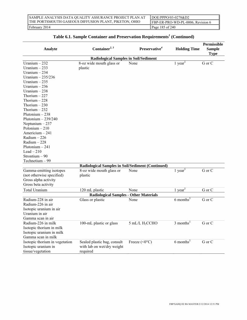
SAMPLE ANALYSIS DATA QUALITY ASSURANCE PROJECT PLAN AT THE PORTSMOUTH GASEOUS DIFFUSION PLANT, PIKETON, OHIO
DOE/PPPO/03-0278&D2 FBP-ER-PRO-WD-PL-0006, Revision 6
February 2014 Page 185 of 240
FBP/SADQ D2 R6 MASTER/2/12/2014 12:51 PM
Table 6.1. Sample Container and Preservation Requirements1 (Continued)
Analyte Container2, 3 Preservative4 Holding TimePermissible
Sample Type
Radiological Samples in Soil/SedimentUranium – 232 Uranium – 233 Uranium – 234 Uranium – 235/236 Uranium – 235 Uranium – 236 Uranium – 238 Thorium – 227 Thorium – 228 Thorium – 230 Thorium – 232 Plutonium – 238 Plutonium – 239/240 Neptunium – 237 Polonium – 210 Americium – 241 Radium – 226 Radium – 228 Plutonium – 241 Lead – 210 Strontium – 90 Technetium – 99
8-oz wide mouth glass or plastic
None 1 year5 G or C
Radiological Samples in Soil/Sediment (Continued)Gamma-emitting isotopes (not otherwise specified) Gross alpha activity Gross beta activity
8-oz wide mouth glass or plastic
None 1 year5 G or C
Total Uranium 120 mL plastic None 1 year5 G or C Radiological Samples - Other Materials
Radium-228 in air Radium-226 in air Isotopic uranium in air Uranium in air Gamma scan in air
Glass or plastic None 6 months5 G or C
Radium-226 in milk Isotopic thorium in milk Isotopic uranium in milk Gamma scan in milk
100-mL plastic or glass 5 mL/L H3CCHO 3 months5 G or C
Isotopic thorium in vegetation Isotopic uranium in tissue/vegetation
Sealed plastic bag, consult with lab on wet/dry weight required
Freeze (<0°C) 6 months5 G or C

SAMPLE ANALYSIS DATA QUALITY ASSURANCE PROJECT PLAN AT THE PORTSMOUTH GASEOUS DIFFUSION PLANT, PIKETON, OHIO
DOE/PPPO/03-0278&D2 FBP-ER-PRO-WD-PL-0006, Revision 6
February 2014 Page 186 of 240
FBP/SADQ D2 R6 MASTER/2/12/2014 12:51 PM
Table 6.1. Sample Container and Preservation Requirements1 (Continued)
Analyte Container2, 3 Preservative4 Holding TimePermissible
Sample Type
Concentrated Waste SamplesFlash point and/or heat content 8-oz wide mouth glass with
Teflon liner None, but cool is recommended6
ASAP G
Metals and other inorganic compoundsA
8-oz wide mouth glass with Teflon liner
Cool6 6 months G or C
Semi-volatile compounds,D benzidines, herbicides, organo-phosphate pesticides, organochlorine, pesticides/PCBs, phthalate esters
8-oz (250-mL) wide mouth glass with Teflon liner
Cool6 14/40 days8,13 G or C
TCLP MercuryD 500-mL glass with Teflon-lined lid
Cool6 28 days G or C
TCLP Metals, except mercuryD 500-mL glass with Teflon-lined lid
Cool6 180 days G or C
TCLP Semi-volatile organic compoundsD
500-mL glass with Teflon-lined lid
Cool6 14/7/40 days7 G or C
TCLP Volatile Organic CompoundsD
250-mL glass with Teflon-lined lid (no headspace to the extent practical)
Cool6 14 days G or C
Volatile organic compounds
(See Soil, Sediment, or Sludge Samples – Low to Medium Concentration section for guidance)
Fish SamplesMercury Place in plastic ziplock bag Freeze 28 days G or C Metals and other inorganic compounds except mercuryA
Place in plastic ziplock bag Freeze 6 months G or C
Semi-volatile compoundsA, organochlorine pesticides/PCBs, herbicides, organo-phosphate pesticides
Wrap in aluminum foil Freeze 14/40 days8,13 G or C
Liquid - Low to Medium Concentration SamplesAcrolein and acrylonitrileB, D
(NPDES samples only) Four 40-mL vials with Teflon-lined septum closure
Cool6, If analyzing for acrolein, then adjust pH <4-5 using H2SO4, or solid NaHSO4
14 days G or C
AlkalinityB 500-mL or 1-L polyethylene with polyethylene-lined closure
Cool6 14 days G or C
AmmoniaB 1-L polyethylene with polyethylene-lined closure
Cool6, H2SO4 to pH <2
28 days G or C
Bioassay, StaticC 1-gal amber glass (not solvent rinsed)
Cool6 36 hours G or C
BOD and CBODB 2-L polyethylene with polyethylene closure
Cool6 48 hours G or C
CODB 250 mL polyethylene with polyethylene-lined closure
Cool6, H2SO4 to pH <2
28 days G
ChlorideB, D 500-mL or 1-L polyethylene with polyethylene-lined closure
None 28 days G or C

SAMPLE ANALYSIS DATA QUALITY ASSURANCE PROJECT PLAN AT THE PORTSMOUTH GASEOUS DIFFUSION PLANT, PIKETON, OHIO
DOE/PPPO/03-0278&D2 FBP-ER-PRO-WD-PL-0006, Revision 6
February 2014 Page 187 of 240
FBP/SADQ D2 R6 MASTER/2/12/2014 12:51 PM
Table 6.1. Sample Container and Preservation Requirements1 (Continued)
Analyte Container2, 3 Preservative4 Holding TimePermissible
Sample Type
Liquid - Low to Medium Concentration Samples (continued) Chlorine ResidualB, D 250-mL or 500-mL
polyethylene or glass None 24 hours G
Chromium, HexavalentB, D 1-L polyethylene with polyethylene closure
Cool6 24 hours G
Coliform, TotalB 250-mL glass with glass closure or plastic capable of being autoclaved
Cool6, 0.008% Na2S2O3/L, if residual Cl is present
6 hours G or C
ColorB 500-mL or 1-L polyethylene with polyethylene-lined closure
Cool6 48 hours G or C
ConductivityB 500-mL or 1-L polyethylene with polyethylene-lined closure
Cool6 28 days G or C
Cyanide, Total or AmenableB, D
1-L or 2-gal polyethylene with polyethylene-lined closure
Cool6, Ascorbic acid9, NaOH to pH >12
14 days G
Dioxins and FuransD 1- or 2.5-gal amber glass with Teflon liner
Cool6 None G or C
Dissolved Oxygen (probe)B In situ None Immediate (in field)
G
Dissolved Oxygen (Winkler)B 300-mL glass (BOD bottle) Fix on site, store in dark
8 hours G
FluorideB 500-mL or 1-L polyethylene with polyethylene-lined closure
None 28 days G or C
HardnessB 500-mL or 1-L polyethylene with polyethylene-lined closure
HNO3 or H2SO4 to pH <2
6 months G or C
MercuryB, D 1-L polyethylene or glass with polyethylene-lined closure
HNO3 to pH <2 28 days G or C
Mercury, DissolvedB, D 1-L polyethylene or glass with polyethylene-lined closure
Filter on site,HNO3 to pH <2
28 days G
Mercury, Low LevelE 500-mL glassE Cool6, (Sample is chemically preserved upon receipt at laboratory per Method 1669F)
28 days G
Metals, Dissolved, except mercuryB, D
1-L polyethylene with polyethylene-lined closure
Filter on site, HNO3 to pH <2
6 months G
Metals, except mercury and hexavalent chromiumB, D
1-L polyethylene with polyethylene-lined closure
HNO3 to pH <2 6 months G or C
NitrateB, D 250 mL polyethylene with polyethylene-lined closure
Cool6 48 hours G or C
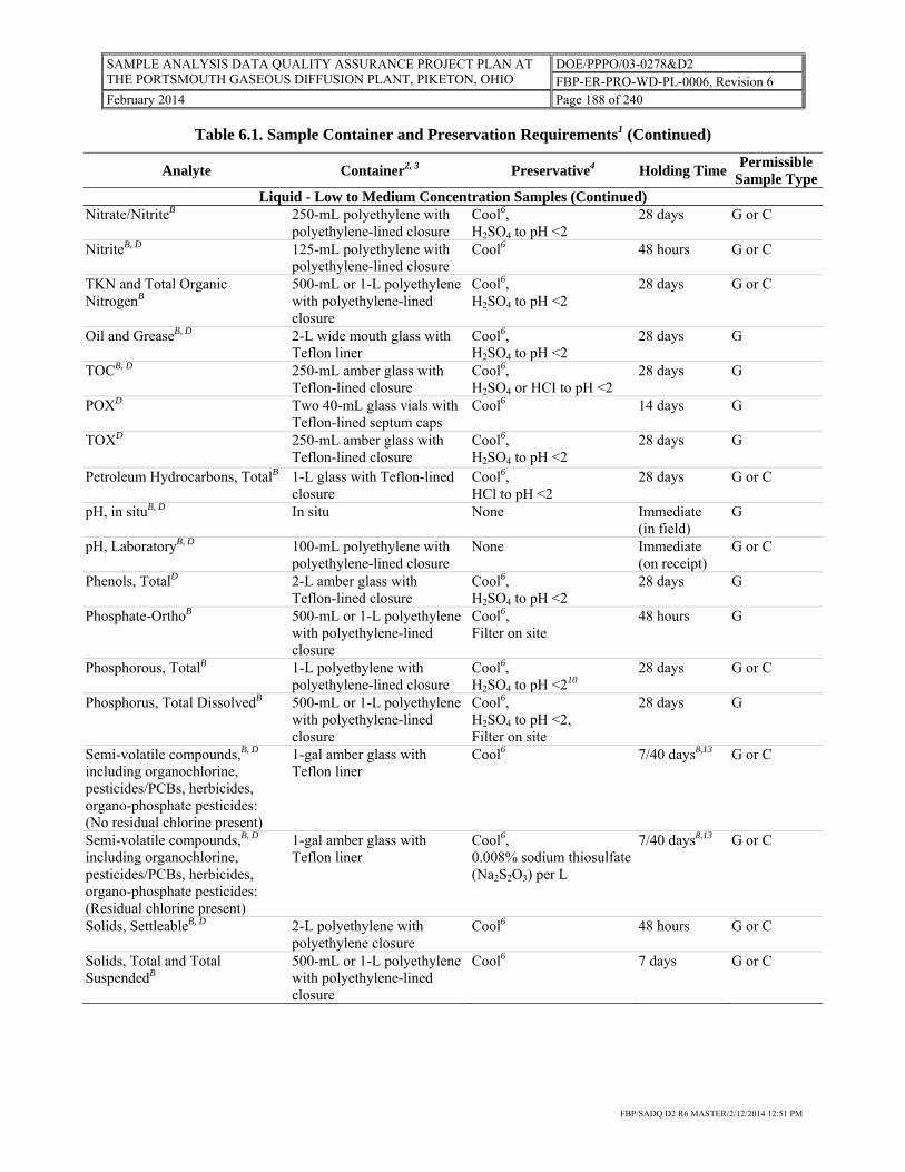
SAMPLE ANALYSIS DATA QUALITY ASSURANCE PROJECT PLAN AT THE PORTSMOUTH GASEOUS DIFFUSION PLANT, PIKETON, OHIO
DOE/PPPO/03-0278&D2 FBP-ER-PRO-WD-PL-0006, Revision 6
February 2014 Page 188 of 240
FBP/SADQ D2 R6 MASTER/2/12/2014 12:51 PM
Table 6.1. Sample Container and Preservation Requirements1 (Continued)
Analyte Container2, 3 Preservative4 Holding Time Permissible
Sample TypeLiquid - Low to Medium Concentration Samples (Continued)
Nitrate/NitriteB 250-mL polyethylene with polyethylene-lined closure
Cool6, H2SO4 to pH <2
28 days G or C
NitriteB, D 125-mL polyethylene with polyethylene-lined closure
Cool6 48 hours G or C
TKN and Total Organic NitrogenB
500-mL or 1-L polyethylene with polyethylene-lined closure
Cool6, H2SO4 to pH <2
28 days G or C
Oil and GreaseB, D 2-L wide mouth glass with Teflon liner
Cool6, H2SO4 to pH <2
28 days G
TOCB, D 250-mL amber glass with Teflon-lined closure
Cool6, H2SO4 or HCI to pH <2
28 days G
POXD Two 40-mL glass vials with Teflon-lined septum caps
Cool6 14 days G
TOXD 250-mL amber glass with Teflon-lined closure
Cool6, H2SO4 to pH <2
28 days G
Petroleum Hydrocarbons, TotalB 1-L glass with Teflon-lined closure
Cool6, HCl to pH <2
28 days G or C
pH, in situB, D In situ None Immediate (in field)
G
pH, LaboratoryB, D 100-mL polyethylene with polyethylene-lined closure
None Immediate (on receipt)
G or C
Phenols, TotalD 2-L amber glass with Teflon-lined closure
Cool6, H2SO4 to pH <2
28 days G
Phosphate-OrthoB 500-mL or 1-L polyethylene with polyethylene-lined closure
Cool6, Filter on site
48 hours G
Phosphorous, TotalB 1-L polyethylene with polyethylene-lined closure
Cool6, H2SO4 to pH <210
28 days G or C
Phosphorus, Total DissolvedB 500-mL or 1-L polyethylene with polyethylene-lined closure
Cool6, H2SO4 to pH <2, Filter on site
28 days G
Semi-volatile compounds,B, D including organochlorine, pesticides/PCBs, herbicides, organo-phosphate pesticides: (No residual chlorine present)
1-gal amber glass with Teflon liner
Cool6
7/40 days8,13 G or C
Semi-volatile compounds,B, D including organochlorine, pesticides/PCBs, herbicides, organo-phosphate pesticides: (Residual chlorine present)
1-gal amber glass with Teflon liner
Cool6, 0.008% sodium thiosulfate (Na2S2O3) per L
7/40 days8,13 G or C
Solids, SettleableB, D 2-L polyethylene with polyethylene closure
Cool6 48 hours G or C
Solids, Total and Total SuspendedB
500-mL or 1-L polyethylene with polyethylene-lined closure
Cool6 7 days G or C

SAMPLE ANALYSIS DATA QUALITY ASSURANCE PROJECT PLAN AT THE PORTSMOUTH GASEOUS DIFFUSION PLANT, PIKETON, OHIO
DOE/PPPO/03-0278&D2 FBP-ER-PRO-WD-PL-0006, Revision 6
February 2014 Page 189 of 240
FBP/SADQ D2 R6 MASTER/2/12/2014 12:51 PM
Table 6.1. Sample Container and Preservation Requirements1 (Continued)
Analyte Container2, 3 Preservative4 Holding Time Permissible
Sample TypeLiquid - Low to Medium Concentration Samples (Continued)
Solids, Total DissolvedB 1-L polyethylene with polyethylene or polyethylene-lined closure
Cool6 7 days G or C
SulfateB 500-mL or 1-L polyethylene with polyethylene-lined closure
Cool6 28 days G or C
SulfideB, D 500-mL polyethylene with polyethylene-lined closure
Cool6, NaOH pH >9, 4 drops 2N zinc acetate per 100 mL of sample
7 days G
SulfiteB, D 125-mL polyethylene with polyethylene-lined closure
None Immediate
G or C
Surfactants (MBAS)B 500-mL polyethylene with polyethylene-lined closure
Cool6 48 hours G or C
TemperatureB In situ None Immediate (in field)
G
Volatile organic compounds: no residual chlorine presentB, D, 11
Four 40-mL glass vials with Teflon-lined septum caps
Cool6, H2SO4, HCI, or solid NaHSO4 to pH <2
14 days G
Volatile organic compounds: no residual chlorine presentB, D, 11
Four 40-mL glass vials with Teflon-lined septum caps
Cool6 7 days G
Volatile organic compounds: residual chlorine present drinking waterB, D, 11
Four 40-mL glass vials with Teflon-lined septum caps
See Note 12 7 days G
Soil, Sediment, or Sludge Samples - Low to Medium Concentration Chlorinated HydrocarbonsD 8-oz (250-mL) wide mouth
glass with Teflon liner Cool6 14/40 days8 G or C
CyanideD 8-oz wide mouth glass with Teflon- or plastic-lined closure
Cool6 14 days G or C
Dioxins and FuransD 8-oz (250-mL) wide mouth amber glass with Teflon liner
Cool6 None G or C
Hexavalent ChromiumD 8-oz (250-mL) wide mouth glass with Teflon- or plastic-lined closure
Cool6 30/4 days8 G or C
MercuryD 8-oz (250-mL) wide mouth plastic or glass
Cool6 28 days G or C
Metals, except mercury and hexavalent chromiumD
8-oz (250-mL) wide mouth glass with Teflon- or plastic-lined closure
None 6 months G or C
Nutrients, including ammonia, TKN, nitrite (NO2), nitrate (NO3), nitrogen, and total phosphateA
8-oz wide mouth glass Cool6 Refer to analytical method
G or C
Petroleum hydrocarbons, totalD 250-mL glass with Teflon-lined closure
Cool6 14/40 days8 G or C
Polynuclear aromatic hydrocarbonsD
8-oz (250-mL) wide mouth glass with Teflon-lined closure
Cool6 14/40 days8 G or C

SAMPLE ANALYSIS DATA QUALITY ASSURANCE PROJECT PLAN AT THE PORTSMOUTH GASEOUS DIFFUSION PLANT, PIKETON, OHIO
DOE/PPPO/03-0278&D2 FBP-ER-PRO-WD-PL-0006, Revision 6
February 2014 Page 190 of 240
FBP/SADQ D2 R6 MASTER/2/12/2014 12:51 PM
Table 6.1. Sample Container and Preservation Requirements1 (Continued)
Analyte Container2, 3 Preservative4 Holding Time Permissible
Sample TypeSoil, Sediment, or Sludge Samples - Low to Medium Concentration (continued)
Semi-volatile compounds,D benzidines, herbicides, organo-phosphate pesticides, organochlorine, pesticides/PCBs, phthalate esters
8-oz (250-mL) wide mouth glass with Teflon-lined closure
Cool6 14/40 days8,13 G or C
TCLP MercuryD 250-mL plastic or glass Cool6 28 days G or C TCLP Metals, except mercuryD 250-mL plastic or glass Cool6 180 days G or C TCLP Semi-volatile organic compoundsD
4-oz (125-mL) glass with Teflon-lined closure
Cool6 14/7/40 days7
G or C
TCLP Volatile organic compoundsD
Two 2-oz (60-mL) wide mouth glass with Teflon septum liner (no headspace to the extent practical)
Cool6 14 days G
Volatile organic compoundsG Three 5 g EncoreTM Samplersand One 2-oz (60-mL) wide mouth glass for percent moisture analysis (no headspace to the extent practical)
Cool6 7 days G
Volatile organic compoundsG Three 40 mL VOA vials, tared or pre-weighed and
Cool6 or freeze (0 to -20°C)
7 days G
One 2-oz (60-mL) wide mouth glass for percent moisture analysis (no headspace to the extent practical)
Cool6
Notes 1. Table 6.1 specifies sample preservation and container requirements for analytes that are regularly collected, as
well as certain analytes that were historically sampled and/or may be sampled in the future. All analytes must be tested with appropriate, specified methods, unless another method has been justified in the SAP. The samplers should use this as a guide and refer to EPA sampling guidance to check for updates and/or revisions.
2. Sample volumes listed are suggested only and may vary according to the analytes requested, analytical method,
and/or QC requirement. Check SAP or DQO for specific volume required. 3. Non-volatile radiological and metal soil samples (including mercury) may be collected into a plastic liner using
direct-push methods, followed by placement of end caps on the liner to containerize the sample for delivery to the laboratory.
4. If sample requires chemical preservation, preserve the sample to the appropriate pH while ensuring that
Department of Transportation hazardous material thresholds are not exceeded for the preservative. The matrix or buffering capacity of the sample may make this infeasible. In such instances, the reason for infeasibility must be appropriately documented in the field logbook. Additional preservative beyond the prescribed initial volume should only be added at the Project Manager’s request due to the following issues: 1) may cause the sample to be diluted, 2) may cause a requirement for additional shipping restrictions (i.e., make the sample a hazardous waste), and/or 3) may not be possible due to buffering capacity of the sample matrix.

SAMPLE ANALYSIS DATA QUALITY ASSURANCE PROJECT PLAN AT THE PORTSMOUTH GASEOUS DIFFUSION PLANT, PIKETON, OHIO
DOE/PPPO/03-0278&D2 FBP-ER-PRO-WD-PL-0006, Revision 6
February 2014 Page 191 of 240
FBP/SADQ D2 R6 MASTER/2/12/2014 12:51 PM
Table 6.1. Sample Container and Preservation Requirements1 (Continued)
5. Holding time is the listed holding time OR less than two times the half-life of the radionuclide of concern, whichever holding time is less.
6. Cool to ≤ 6°C. 7. For holding times listed as xx/yy/zz days, the first number is the allowed holding time from field collection to
TCLP extraction, the second number is the allowed holding time from TCLP extraction to preparative extraction, and the third number is the allowed holding time from preparative extraction to analysis of the extract.
8. For holding times listed as xx/yy days, the first number is the allowed holding time for extraction or preparation
of the sample for analysis and the second number is the allowed holding time for analysis of the extract. 9. Use ascorbic acid only if the sample contains residual chlorine. If residual chlorine is suspected, test a drop of
the sample with potassium iodide-starch test paper. A blue color indicates need for treatment. Add ascorbic acid, a few crystals at a time, until a drop of sample produces no color on the indicator paper, and then add an additional 0.6 grams of ascorbic acid for each liter of sample volume.
10. If method 4500-P is to be used to determine total phosphorus, add 1 mL concentrated HCl or freeze at or below
-10°C without any additions. 11. Samples must have zero headspace. 12. Collect the sample in a 4-oz soil VOA container that has been pre-preserved with four drops of 10 percent
sodium thiosulfate (Na2S2O3) solution. Cool to < 6°C. 13. PCBs have no hold time prior to sample extraction. Abbreviations/Acronyms ASAP = as soon as possible PCB = polychlorinated biphenyl BOD = biochemical oxygen demand POX = purgeable organic halogens C = composite QC = quality control CBOD = carbonaceous biological oxygen demand SAP = sampling and analysis plan CFR = Code of Federal Regulations SR = sample request COD = chemical oxygen demand TCLP = Toxicity Characteristic Leaching Procedure DQO = data quality objective TKN = total Kjeldhahl nitrogen EPA = U.S. Environmental Protection Agency TOC = total organic carbon G = Grab TOX = total organic halogens MBAS = methylene blue active substance VOA = volatile organic analysis NPDES = National Pollutant Discharge Elimination System
Sources A EPA Region IV, Environmental Services Division, Analytical Support Branch, Operations and Quality Control
Manual, November 2001 or latest version. B 40 CFR Part 136. C EPA Region IV, Environmental Services Division, Ecological Support Branch, Standard Operating Procedures
Manual, latest version.
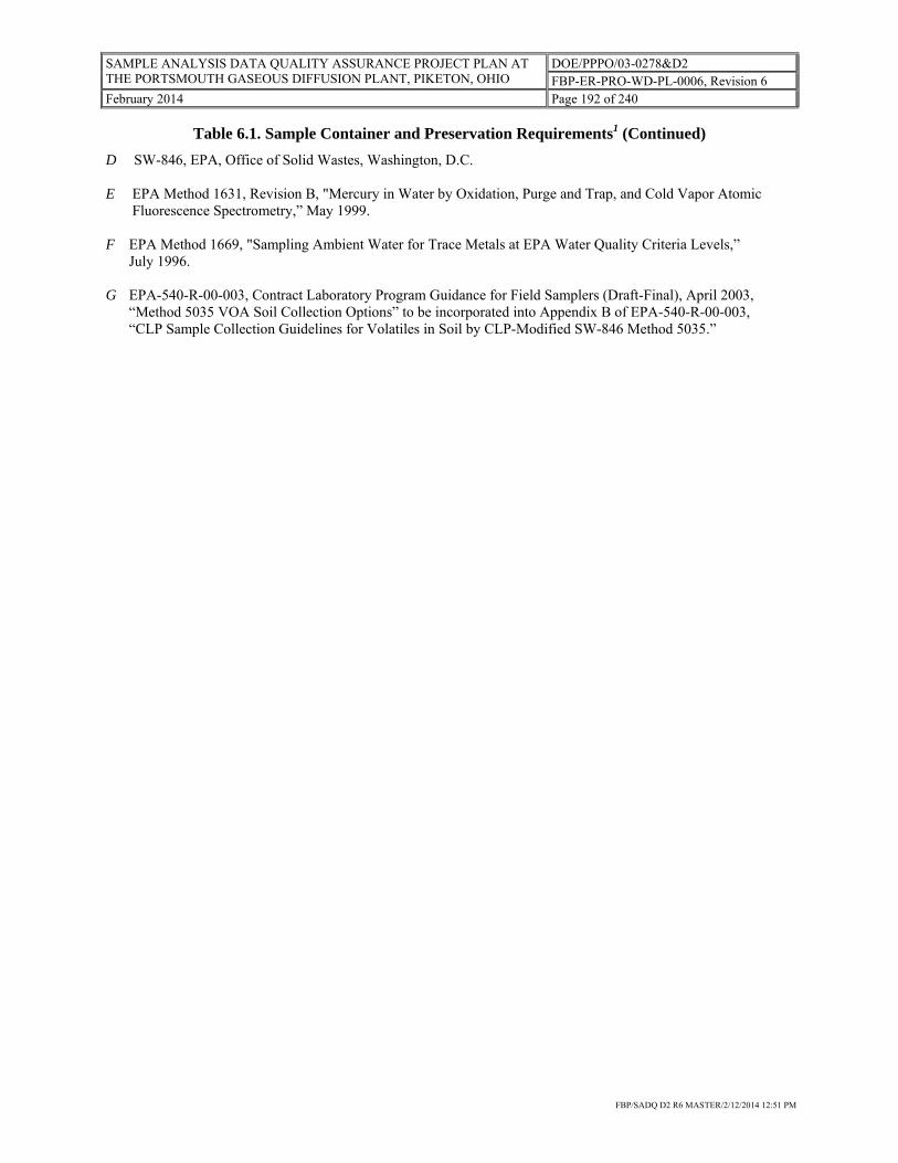
SAMPLE ANALYSIS DATA QUALITY ASSURANCE PROJECT PLAN AT THE PORTSMOUTH GASEOUS DIFFUSION PLANT, PIKETON, OHIO
DOE/PPPO/03-0278&D2 FBP-ER-PRO-WD-PL-0006, Revision 6
February 2014 Page 192 of 240
FBP/SADQ D2 R6 MASTER/2/12/2014 12:51 PM
Table 6.1. Sample Container and Preservation Requirements1 (Continued)
D SW-846, EPA, Office of Solid Wastes, Washington, D.C. E EPA Method 1631, Revision B, "Mercury in Water by Oxidation, Purge and Trap, and Cold Vapor Atomic
Fluorescence Spectrometry,” May 1999. F EPA Method 1669, "Sampling Ambient Water for Trace Metals at EPA Water Quality Criteria Levels,”
July 1996. G EPA-540-R-00-003, Contract Laboratory Program Guidance for Field Samplers (Draft-Final), April 2003,
“Method 5035 VOA Soil Collection Options” to be incorporated into Appendix B of EPA-540-R-00-003, “CLP Sample Collection Guidelines for Volatiles in Soil by CLP-Modified SW-846 Method 5035.”

SAMPLE ANALYSIS DATA QUALITY ASSURANCE PROJECT PLAN AT THE PORTSMOUTH GASEOUS DIFFUSION PLANT, PIKETON, OHIO
DOE/PPPO/03-0278&D2 FBP-ER-PRO-WD-PL-0006, Revision 6
February 2014 Page 193 of 240
FBP/SADQ D2 R6 MASTER/2/12/2014 12:51 PM
Table 10.1. Minimum Preventive Maintenance for Commonly Used Field Equipment
Equipment Type Maintenance Minimum Frequency Spare Parts
Photoionization detector Clean lamp Charge battery Change filter Factory service
40 hours of Operation As needed 240 hours of operation Yearly
Lamp Filters
pH meter Check battery Clean electrode Check connectors Factory Service
With each use Monthly With each use Annual
Batteries Electrode
Specific conductance meter Check battery Clean probe Check connectors Inspect cable Factory Service
With each use Monthly Daily With each use Annual
Batteries Probe
Dissolved oxygen meter Check battery Clean probe Check cable and connectors Factory Service
Daily Monthly With each use Annual
Batteries
Radiological Field Screen Instrument
Check Battery Clean probe exterior Check connectors Factory Service
With each use As needed With each use As needed
Batteries
Thermometers Clean and check for cracks With each use
Water level indicator Check battery Clean probe Accuracy check
With each use As needed Annually
Batteries
Pressure transducers Check cables Clean probe Zero check
With each use As needed Annually
Water quality meter Check battery Clean probe Inspect cable Replace sensors Check connections Factory service
With each use After each use With each use As needed With each use Annual
Note: Calibration and service frequency will be performed as per method or manufacture specification.

SAMPLE ANALYSIS DATA QUALITY ASSURANCE PROJECT PLAN AT THE PORTSMOUTH GASEOUS DIFFUSION PLANT, PIKETON, OHIO
DOE/PPPO/03-0278&D2 FBP-ER-PRO-WD-PL-0006, Revision 6
February 2014 Page 194 of 240
FBP/SADQ D2 R6 MASTER/2/12/2014 12:51 PM
Table 12.1. Field Quality Control Samples for ASLs A, B, C, and D
Inorganics, Organics, and Radionuclides Frequency
Field Quality Control Samples
Analytical Support Level A/B Analytical Support Level C/D
Field Blanksa 1 per 20 samples 1 per 20 samplesb
Equipment rinsate samplesa,c AS 1 per 20 samplesb
Field duplicates AS 1 per 20 samplesb
Preservative blanks AS AS
Container blanks AS AS
Trip blanks AS 1 per shipping container containing VOCs
Split samples AS AS
Field spike AS 1 per sampling roundb, if specified
Equipment/material blanksd AS 1 per 20 samplesb
aNot required for radiological sampling activities unless defined in the sample request or SAP. bSAPs may define requirements for sampling round, which refers to collection of samples from one or more locations for a specific project during a specified time period for a similar purpose.
cAn equipment rinsate sample is not required for dedicated equipment. dAn equipment/material blank is applicable to sampling equipment. AS = as specified SAP = sampling and analysis plan VOC = volatile organic compound

SAMPLE ANALYSIS DATA QUALITY ASSURANCE PROJECT PLAN AT THE PORTSMOUTH GASEOUS DIFFUSION PLANT, PIKETON, OHIO
DOE/PPPO/03-0278&D2 FBP-ER-PRO-WD-PL-0006, Revision 6
February 2014 Page 195 of 240
FBP/SADQ D2 R6 MASTER/2/12/2014 12:51 PM
Table 12.2. General Laboratory Quality Control Specifications for ASLs A, B, C, and D
Inorganic Analyses Frequency Method Blank 1/20 samples or analytical batch, whichever is more
frequent (per matrix) as applicable to the analytical method.
Laboratory Control Sample 1/20 samples or analytical batch, whichever is more frequent (per matrix) as applicable to the analytical method.
Duplicate 1/20 samples or analytical batch, whichever is more frequent (per matrix) as applicable to the analytical method.
Matrix Spike 1/20 samples or analytical batch, whichever is more frequent (per matrix) as applicable to the analytical method.
Organic Analyses Frequency Method Blank 1/20 samples or analytical batch, whichever is more
frequent (per matrix) as applicable to the analytical method.
Laboratory Control Sample 1/20 samples or analytical batch, whichever is more frequent (per matrix) as applicable to the analytical method.
Matrix Spike 1/20 samples or analytical batch, whichever is more frequent (per matrix) as applicable to the analytical method.
Matrix Spike Duplicate 1/20 samples or analytical batch, whichever is more frequent (per matrix) as applicable to the analytical method.
Radiochemical Analyses Frequency Reagent Blank 1/20 samples or analytical batch, whichever is more
frequent (per matrix) as applicable to the analytical method.
Laboratory Control Sample Same as above. The laboratory control sample shall include at least one radioisotope from those being analyzed when using alpha and gamma counting techniques.
Duplicate or Matrix Spike Duplicate 1/20 samples or analytical batch, whichever is more frequent (per matrix) as applicable to analytical method.
Matrix Spike 1/20 samples or analytical batch, whichever is more frequent (per matrix) as applicable to the method.
Note: This table represents the QC that may be typically seen for inorganic, organic, and radiochemical analyses. For more specific guidelines on laboratory QC, refer to the SAP or the applicable analytical method. QC = quality control SAP = sampling and analysis plan

SAMPLE ANALYSIS DATA QUALITY ASSURANCE PROJECT PLAN AT THE PORTSMOUTH GASEOUS DIFFUSION PLANT, PIKETON, OHIO
DOE/PPPO/03-0278&D2 FBP-ER-PRO-WD-PL-0006, Revision 6
February 2014 Page 196 of 240
FBP/SADQ D2 R6 MASTER/2/12/2014 12:51 PM
This page is intentionally left blank.

SAMPLE ANALYSIS DATA QUALITY ASSURANCE PROJECT PLAN AT THE PORTSMOUTH GASEOUS DIFFUSION PLANT, PIKETON, OHIO
DOE/PPPO/03-0278&D2 FBP-ER-PRO-WD-PL-0006, Revision 6
February 2014 Page 197 of 240
FBP/SADQ D2 R6 MASTER/2/12/2014 12:51 PM
APPENDIX B: DATA QUALITY OBJECTIVES

SAMPLE ANALYSIS DATA QUALITY ASSURANCE PROJECT PLAN AT THE PORTSMOUTH GASEOUS DIFFUSION PLANT, PIKETON, OHIO
DOE/PPPO/03-0278&D2 FBP-ER-PRO-WD-PL-0006, Revision 6
February 2014 Page 198 of 240
FBP/SADQ D2 R6 MASTER/2/12/2014 12:51 PM
This page is intentionally left blank.

SAMPLE ANALYSIS DATA QUALITY ASSURANCE PROJECT PLAN AT THE PORTSMOUTH GASEOUS DIFFUSION PLANT, PIKETON, OHIO
DOE/PPPO/03-0278&D2 FBP-ER-PRO-WD-PL-0006, Revision 6
February 2014 Page 199 of 240
FBP/SADQ D2 R6 MASTER/2/12/2014 12:51 PM
CONTENTS
Page ACRONYMS ............................................................................................................................................ 201 B.1. INTRODUCTION ........................................................................................................................... 203 B.2. DATA QUALITY OBJECTIVE LOGIC FLOW PROCESS ......................................................... 204
B.2.1 STATE THE PROBLEM (STEP 1) ................................................................................... 205 B.2.2 IDENTIFY THE GOAL OF THE STUDY (STEP 2) ....................................................... 205 B.2.3 IDENTIFY INFORMATION INPUTS (STEP 3) ............................................................. 206 B.2.4 DEFINE THE BOUNDARIES OF THE STUDY (STEP 4) ............................................. 206 B.2.5 DEVELOP THE ANALYTIC APPROACH (STEP 5) ..................................................... 207 B.2.6 SPECIFY PERFORMANCE OR ACCEPTANCE CRITERIA (STEP 6) ........................ 208 B.2.7 DEVELOP THE PLAN FOR OBTAINING DATA (STEP 7) ......................................... 209 B.2.8 THE DQO PROCESS ........................................................................................................ 210
B.3. REFERENCE .................................................................................................................................. 212

SAMPLE ANALYSIS DATA QUALITY ASSURANCE PROJECT PLAN AT THE PORTSMOUTH GASEOUS DIFFUSION PLANT, PIKETON, OHIO
DOE/PPPO/03-0278&D2 FBP-ER-PRO-WD-PL-0006, Revision 6
February 2014 Page 200 of 240
FBP/SADQ D2 R6 MASTER/2/12/2014 12:51 PM
This page is intentionally left blank.

SAMPLE ANALYSIS DATA QUALITY ASSURANCE PROJECT PLAN AT THE PORTSMOUTH GASEOUS DIFFUSION PLANT, PIKETON, OHIO
DOE/PPPO/03-0278&D2 FBP-ER-PRO-WD-PL-0006, Revision 6
February 2014 Page 201 of 240
FBP/SADQ D2 R6 MASTER/2/12/2014 12:51 PM
ACRONYMS ASL analytical support level DQO data quality objective EPA U.S. Environmental Protection Agency PORTS Portsmouth Gaseous Diffusion Plant QA quality assurance QC quality control SAP sampling and analysis plan

SAMPLE ANALYSIS DATA QUALITY ASSURANCE PROJECT PLAN AT THE PORTSMOUTH GASEOUS DIFFUSION PLANT, PIKETON, OHIO
DOE/PPPO/03-0278&D2 FBP-ER-PRO-WD-PL-0006, Revision 6
February 2014 Page 202 of 240
FBP/SADQ D2 R6 MASTER/2/12/2014 12:51 PM
This page is intentionally left blank.

SAMPLE ANALYSIS DATA QUALITY ASSURANCE PROJECT PLAN AT THE PORTSMOUTH GASEOUS DIFFUSION PLANT, PIKETON, OHIO
DOE/PPPO/03-0278&D2 FBP-ER-PRO-WD-PL-0006, Revision 6
February 2014 Page 203 of 240
FBP/SADQ D2 R6 MASTER/2/12/2014 12:51 PM
B.1. INTRODUCTION All sampling and analysis programs at the Portsmouth Gaseous Diffusion Plant (PORTS) ultimately contribute toward fulfillment of the PORTS mission - the restoration of the environment in accordance with regulations and regulatory agreements identified in the body of the Sample Analysis Data Quality Assurance Project Plan. The samples collected may fulfill one of the following purposes: 1) Identification of potential contamination (e.g., routine monitoring programs, air and water permit
verification, investigation of suspect source areas, sampling of decommissioned equipment and materials during decontamination and decommissioning)
2) Confirmation of contamination (e.g., authoritative sampling of spill areas, collection of samples
from areas targeted during screening investigations, sampling of suspected asbestos-containing materials)
3) Characterization of contamination (e.g., delineation of source areas or plumes by random,
authoritative, or combination methods; sampling of containerized waste) 4) Determination of environmental and human health risks (e.g., risk assessments and environmental
assessments) 5) Alternatives evaluation (e.g., treatability studies) 6) Alternatives design (e.g., remedial design) 7) Monitoring of response actions (e.g., monitoring during response actions, confirmation sampling to
evaluate the effectiveness of a response action) 8) Monitoring to comply with regulations (e.g., the Consent Agreement; The April 13, 2010 Director’s
Final Findings and Orders for Removal Action and Remedial Investigation and Feasibility Study and Remedial Design and Remedial Action, including the July 16, 2012 Modification thereto; the Integration Order; and the U.S. Environmental Protection Agency (EPA) Administrative Consent Order; as well as the Comprehensive Environmental Response, Compensation, and Liability Act of 1980, as amended; the National Pollutant Discharge Elimination System; and the Resource Conservation and Recovery Act of 1976, as amended).
9) Determination of background concentration of contaminants 10) Determination that cleanup levels have been achieved and that the response action can be
terminated, or that the operations and maintenance phase can begin 11) Waste characterization sampling supporting waste storage, packaging, disposal disposition, and
shipping. Data quality objectives (DQOs) (EPA 2006) are scoping and planning tools applicable to sample collection efforts and are a necessary step in the generation of a project-specific plan. DQOs are quantitative and qualitative descriptions of the data required for one of these purposes. As target values for data quality, they are not necessarily criteria for acceptance or rejection of data.

SAMPLE ANALYSIS DATA QUALITY ASSURANCE PROJECT PLAN AT THE PORTSMOUTH GASEOUS DIFFUSION PLANT, PIKETON, OHIO
DOE/PPPO/03-0278&D2 FBP-ER-PRO-WD-PL-0006, Revision 6
February 2014 Page 204 of 240
FBP/SADQ D2 R6 MASTER/2/12/2014 12:51 PM
The DQO process generates a logical set of decisions that determine whether collection of samples is necessary; specifies the types of samples to collect, including quality control (QC) samples; describes the design of the sample collection effort, including the number of samples; specifies analytical requirements, including precision, accuracy, comparability, completeness, and sensitivity of the method; and determines the overall confidence level that the resultant data will meet project requirements. Decisions should be made so that existing data gaps are filled and the resulting data will meet the requirements of its intended use. Since the content and level of detail in individual sampling and analysis plans (SAPs) will vary according to the work being performed and the intended use of the data, planners will want to use a “graded approach” when preparing SAPs. A graded approach is the process of establishing the project requirements and level of effort according to the intended use of the results and the degree of confidence needed in the quality of the results. All steps of the DQO logic flow process should be completed in sequence and be appropriately documented. Analytical support levels (ASLs) must be specified for each analysis. All DQOs will be reviewed and approved by the DQO coordinator.
B.2. DATA QUALITY OBJECTIVE LOGIC FLOW PROCESS The DQO logic flow process presents the rationale for deciding what data are necessary, the quality and type of data required, the data's technical defensibility, and the understanding and minimization of risk throughout the sampling process. The logic flow will help to identify areas of concern, the selection of equipment, quality assurance (QA) requirements, and ASLs. The logic statement is a DQO supporting document that is kept on file. This logic flow process has eight steps: Step 1. State the problem Step 2. Identify the goal of the study Step 3. Identify information inputs Step 4. Define the boundaries of the study Step 5. Develop the analytic approach Step 6. Specify performance or acceptability criteria Step 7. Develop the plan for obtaining data. The steps listed above may not be applicable in all instances, such as routine monitoring plans. Therefore, if a step does not apply, indicate that it is not applicable and provide detailed, complete justification in the logic flow. Do not simply leave a step blank. Graded Approach For data collection activities that are either exploratory or small in nature, or where specific decisions cannot be identified, the formal DQO process is not necessary. For these projects, the project team should use an abbreviated systematic planning process (e.g., Steps 1- 4) to help identify the project quality objectives and action limits, and to select appropriate sampling, analytical, and assessment activities.

SAMPLE ANALYSIS DATA QUALITY ASSURANCE PROJECT PLAN AT THE PORTSMOUTH GASEOUS DIFFUSION PLANT, PIKETON, OHIO
DOE/PPPO/03-0278&D2 FBP-ER-PRO-WD-PL-0006, Revision 6
February 2014 Page 205 of 240
FBP/SADQ D2 R6 MASTER/2/12/2014 12:51 PM
B.2.1 STATE THE PROBLEM (STEP 1) The first step in any systematic planning process, and therefore the DQO Process, is to define the problem that has initiated the study. This step describes problem definition and any resource, time, or other practical limits on data collection. The purpose of Step 1 is to evaluate existing knowledge about the problem and identify available resources. By carefully defining the problem early in the planning process, the planning team can ultimately save time and money. In addition, refinements to the way in which the problem is stated are often made when the planning team better understands the implications of the original problem definition. Define the problem that necessitates the study; identify the planning team, examine budget, schedule. Items to be addressed include, but are not limited to, the following: 1) Identification of the planning team, including but not limited to, senior program staff, technical
experts, risk assessor, senior managers (decision makers) whose planning input will be needed during the process to ensure implementation of the study findings and a statistician (or someone with statistical expertise).
2) Specification of resource or time limits for this study, including the anticipated budget and
availability of key personnel. Identify obvious practical considerations, such as time of year when data collection is not possible. These practical considerations will be expanded upon later in the process.
3) Statement of the problem, including the following elements:
a) Describe the problem, develop a conceptual model of the environmental hazard to be investigated, and identify the general type of data needed
b) Establish the planning team and identify the team’s decision makers c) Discuss alternative approaches to investigation and solving the problem d) Identify and involve project personnel e) Identify available resources, constraints, and deadlines associated with planning, data
collection, and data assessment.
4) Determination of whether new data are critical to resolving this problem. B.2.2 IDENTIFY THE GOAL OF THE STUDY (STEP 2) Step 2 is identification of a primary decision that will address the concern, a list of alternate actions that address the problem, and the actions that will result. If the planning team believes actions may be taken based on the study data, but cannot identify the specific actions, then try to elicit possible actions from the decision maker in order to understand the intended use of the data. The decision should be stated as narrowly and specifically as possible. State how data will be used in meeting objectives and solving the problem, identify study questions, define alternative outcomes. General statements of goals or objectives are not adequate. Items to be addressed include, but are not limited to, the following as appropriate to describing the project goal and objectives:

SAMPLE ANALYSIS DATA QUALITY ASSURANCE PROJECT PLAN AT THE PORTSMOUTH GASEOUS DIFFUSION PLANT, PIKETON, OHIO
DOE/PPPO/03-0278&D2 FBP-ER-PRO-WD-PL-0006, Revision 6
February 2014 Page 206 of 240
FBP/SADQ D2 R6 MASTER/2/12/2014 12:51 PM
1) State the decision so that the role of data is clear in deciding action to be taken.
a) Describe initial ideas on approaches to resolving the problem b) State the range of actions that may be taken based on the outcome of the study. Consider
agency policies that may influence these actions (e.g., agency emphasis on pollution prevention instead of source containment or treatment).
c) Specify criteria for taking these actions as "if..., then..." scenarios when possible. Specify
how unknown criteria will be established. d) State the decision as a choice among alternative courses of action that will resolve one or
more components of the problem. 2) If several separate decisions must be made to address a component of the problem, begin by
mapping out a decision or logic tree. This exercise should reveal the relationship among decisions. Try to find the relative importance of each decision to the complete problem. Decide which decisions require new environmental data and the importance of those data to the decision. Use the DQO process for each decision that requires new data starting with the most important decision. In certain cases, go back and reflect further on the problem. The decision maker (data user) should be involved in Step 2 and is encouraged to provide general guidance for taking action.
B.2.3 IDENTIFY INFORMATION INPUTS (STEP 3) This step discusses identification of environmental variables or characteristics that serve as criteria for taking action and other information needed to make the decision. During Step 3 the planning team should identify all variables or characteristics that may be relevant to the decision and then focus on those that must be measured to provide information needed for the decision. Identify data and information needed to answer study questions. Items to address shall include, but are not limited to, the following as appropriate: 1) Development of a list of variables characteristics that may affect the decision and separation of
those that must be measured to make the decision (which action to take). Identify those variables that together will provide sufficient information to make the decision.
2) Specification of criteria for taking action. Identify information from other studies and regulations
needed to establish the criteria for taking action. 3) Confirmation that each variable (environmental or waste characteristic) can be measured. If it
cannot, decide if it is reasonable to make assumptions about the variable to draw conclusions without data. If the necessary assumptions cannot be defended, conduct a pilot study or select an alternative approach that involves different variables that are measurable.
If no practical approach can be developed, consider shifting the effort to develop the research tools needed to address the problem. Consider not conducting the study at this time. B.2.4 DEFINE THE BOUNDARIES OF THE STUDY (STEP 4) This step concerns development of a statement addressing the domain of the decision. The purpose of Step 4 is to define the population for which the decision will be made (people, objects, portions of media) so that it is clear what belongs in this population and what the boundaries on this population are (area or

SAMPLE ANALYSIS DATA QUALITY ASSURANCE PROJECT PLAN AT THE PORTSMOUTH GASEOUS DIFFUSION PLANT, PIKETON, OHIO
DOE/PPPO/03-0278&D2 FBP-ER-PRO-WD-PL-0006, Revision 6
February 2014 Page 207 of 240
FBP/SADQ D2 R6 MASTER/2/12/2014 12:51 PM
volume and time period). Specify the target population and characteristics of interest, define spatial and temporal limits, and scale of inference. When the population consists of people and objects, it is important to define space and time boundaries and other characteristics to indicate what belongs in and out of the population. Alternatively, the population may consist of a continuous medium (air, water, soil). In this case, the portion of the medium that belongs in the population can usually be defined just by spatial and temporal boundaries, although other characteristics may help to define it further. Sampling from this population may be necessary to make inferences about the population as a whole. Sometimes it is not possible to sample from the entire population; in this case, either make inferences only to that portion of the population that can be measured or make assumptions that allow inference to the entire population. Statistical analysis will be implemented based upon available data on the population. Items to address include, but are not limited to, the following as appropriate: 1) Specify the population for which the decision will be made so that it is clear what belongs in this
population. 2) Define the spatial and temporal boundaries of this population such as compositing or subsampling
strategy. 3) Define additional characteristics needed to decide what belongs in the population such as location
surveys, location identifiers, depth intervals, or unique sample alphanumeric identifications. 4) If applicable, specify the smallest sub-population for which the decision will be made. The cost of
the study usually increases for each sub-population group because more samples are required to estimate the variables within each group.
5) Make sure that practical considerations (Step 1) are consistent with these boundaries. B.2.5 DEVELOP THE ANALYTIC APPROACH (STEP 5) This step describes steps in developing a statement to define how sampling data will be summarized and used to make the decision. After the data for a study are collected, they are summarized to form a result for the study which is compared to the criteria for taking action to make the decision. Define the parameter of interest, specify the type of inference, and develop the logic for drawing conclusions from the findings. The purpose of Step 5 is to integrate output from previous steps into a single statement specifying how environmental data will be summarized and used to make the decision, including quantitative criteria for determining what action to take. It is important to have staff with statistical expertise involved in this step to ensure that the logic statement (decision rule) is written in a way that leads to an efficient sample collection design. Items to be addressed include, but are not limited to, the following as appropriate: 1) Describe the intended study result (the way in which the data will be summarized) and how the
result will be calculated (e.g., mean, range, maximum).

SAMPLE ANALYSIS DATA QUALITY ASSURANCE PROJECT PLAN AT THE PORTSMOUTH GASEOUS DIFFUSION PLANT, PIKETON, OHIO
DOE/PPPO/03-0278&D2 FBP-ER-PRO-WD-PL-0006, Revision 6
February 2014 Page 208 of 240
FBP/SADQ D2 R6 MASTER/2/12/2014 12:51 PM
2) Develop a decision rule as an "if..., then..." statement that incorporates the study result, criteria for taking action, and actions that will be taken under various possible scenarios.
Example: If, in the monthly sample, X analyte exceeds Y ppm for two sampling periods, increase sample frequency to weekly. In this example, the study result is the X analyte, the criterion for taking action is the maximum allowable concentration of Y ppm being exceeded in two out of four consecutive sampling periods, and the actions are to increase the sampling analysis frequency to weekly.
3) Confirm that all data collected are necessary; if they are not, define a more narrowly focused set of
input variables. 4) Consider uses of the data by other programs. For example, if the primary reason for collecting the
data is to determine the nature and extent of potential groundwater contamination, could the same data be used in a risk assessment? If so, the DQOs should include the additional potential uses of the data.
B.2.6 SPECIFY PERFORMANCE OR ACCEPTANCE CRITERIA (STEP 6) This step discusses the development of constraints on uncertainty. The decision maker’s expressed need to control decision errors should be stated as limits on the acceptable probability of making an incorrect decision based on the study findings. Specify probability limits for false rejection and false acceptance decision errors. These limits on uncertainty may be expressed as acceptable false positive and false negative error rates. There is always some error in data and as a result, some degree of uncertainty will exist in any decision based on these data. The limits on uncertainty should be based on careful consideration of the consequences of incorrect conclusions. The planning team will need to estimate the economic, health, and ecological consequences of decision errors. Also, the decision maker will need to consider the political and social consequences when setting limits on uncertainty. The decision maker (data user) needs to be actively involved in the specification of limits on uncertainty. In addition, the planning team should work with a statistician during Step 6 to ensure that the limits are reasonable and complete. There are two types of decision errors that may occur in studies that will be used to support a decision on whether to take action: false positives and false negatives. The definition of what constitutes false positive and false negative errors depends on how the decision is defined. Consult a statistician if there are questions. Limits on uncertainty for these studies can be expressed as limits on the acceptable rates of false positive and false negative errors. The uncertainty associated with data and the inherent natural variability make it unreasonable (very expensive) to find small differences in an environmental variable. When true conditions are very close to the criterion for taking action, it is difficult (if not impossible) to determine if conditions are above or below the criterion. To respond to this problem, consider defining a region of indifference where either decision is acceptable. This region may be placed around, at, or below the criteria for taking action, depending on the decision being made. The width of this interval can vary, but generally, the cost of the study increases with a narrower region of indifference.

SAMPLE ANALYSIS DATA QUALITY ASSURANCE PROJECT PLAN AT THE PORTSMOUTH GASEOUS DIFFUSION PLANT, PIKETON, OHIO
DOE/PPPO/03-0278&D2 FBP-ER-PRO-WD-PL-0006, Revision 6
February 2014 Page 209 of 240
FBP/SADQ D2 R6 MASTER/2/12/2014 12:51 PM
Items to address shall include, but are not limited to, the following as appropriate: 1) Define false positive (f(+)) and false negative (f(-)) errors for the decision (decision errors) and
describe scenarios in which each type of error might take place. 2) Order the importance of expected economic, ecological, health, political and social consequences
according to the level of concern the decision maker has with each. Consider the possible regulatory, customer, or stakeholder concerns.
3) Determine if false positive or false negative errors are of greater concern. 4) Determine whether the level of concern for either type of decision error depends on the magnitude
of the error (e.g., a case where there is a threshold below which a decision error leads to economic consequences and above which it also leads to adverse health effects). The decision maker should be more concerned about a larger decision error that has both health and economic consequences.
5) Consider the estimated magnitude of the expected consequences and decide what magnitude of
false positive and false negative errors would be almost always, often, sometimes, or almost never acceptable. It may not be necessary to assign values to all four categories.
6) Establish, with statistical advice, an acceptable probability for the occurrence of each of these
errors. Also, specify a region of indifference (the area in which you choose not to control the probability of an incorrect outcome because, under the stated conditions, either decision is acceptable). This region may be narrow or broad and must be acceptable to the decision maker.
7) Combine the probability statements into a formal statement of the levels of uncertainty that can be
tolerated in the results. This formal statement may take the form of a table or graph. Develop performance criteria for new data being collected or acceptable criteria for existing data being considered for use. If a statistician is part of the team or is being consulted, a slightly different terminology is used. In the statistical language of hypothesis testing, the baseline condition is called the null hypothesis (Ho) and the alternative condition is called the alternative hypothesis (Ha). Statisticians interpret decision errors as follows: A false rejection decision error, or a Type I error, occurs when you reject the null hypothesis when it
is actually true. The probability of this error occurring is called alpha (α) and is called the hypothesis test’s level of significance.
A false acceptance decision error, or a Type II error, occurs when you fail to reject the null hypothesis
when it is actually false. The probability that this error will occur is called beta (β). Frequently, a false rejection decision error is the more severe decision error, and therefore, criteria
placed on an acceptable value of alpha (α) are typically more stringent than for beta (β). B.2.7 DEVELOP THE PLAN FOR OBTAINING DATA (STEP 7) This step addresses how to optimize data collection by identifying the most efficient plan that will achieve the desired constraints on uncertainty. Select the resource-effective sampling and analysis plan that meets

SAMPLE ANALYSIS DATA QUALITY ASSURANCE PROJECT PLAN AT THE PORTSMOUTH GASEOUS DIFFUSION PLANT, PIKETON, OHIO
DOE/PPPO/03-0278&D2 FBP-ER-PRO-WD-PL-0006, Revision 6
February 2014 Page 210 of 240
FBP/SADQ D2 R6 MASTER/2/12/2014 12:51 PM
the performance criteria. Items to address shall include, but are not limited to, the following, as appropriate: 1) What are the estimated variabilities and distributions of related contaminants of potential concern? 2) Based on existing estimates of variabilities and distributions of contaminants of potential concern
and relative costs of proposed sampling and analysis options, what is the lowest cost sampling and analysis plan that will achieve the desired data and constraints on uncertainty (i.e., how many samples will be collected; how will sampling points be identified or chosen; what is the sampling method; how frequently will samples be collected; what level of QC is required; what are the requirements for precision, accuracy, sensitivity, and completeness; and what analytical methods are appropriate)?
Performing Steps 1 through 6 of the DQO process generates a set of performance or acceptance criteria that the collected data will need to achieve. The goal of Step 7 is to develop a resource-effective design for collecting and measuring environmental samples, or for generating other types of information needed to address the problem. This corresponds to generating either: (a) the most resource-effective data collection process that is sufficient to fulfill study objectives, or (b) a data collection process that maximizes the amount of information available for synthesis and analysis within a fixed budget. In addition, this design will lead to data that will achieve your performance or acceptance criteria B.2.8 THE DQO PROCESS The DQO process is used to establish performance or acceptance criteria, which serve as the basis for designing a plan for collecting data of sufficient quality and quantity to support the goals of a study. The DQO process consists of seven iterative steps that are documented in Figure B.1. While the interaction of these steps is portrayed in Figure B.1 in a sequential fashion, the iterative nature of the DQO process allows one or more of these steps to be revisited as more information on the problem is obtained. Each step of the DQO Process defines criteria that will be used to establish the final data collection design. The first five steps are primarily focused on identifying qualitative criteria, such as: Nature of the problem that has initiated the study and a conceptual model of the environmental hazard
to be investigated Decisions or estimates that need to be made and the order of priority for resolving them Type of data needed Analytic approach or decision rule that defines the logic for how the data will be used to draw
conclusions from the study findings.

SAMPLE ANALYSIS DATA QUALITY ASSURANCE PROJECT PLAN AT THE PORTSMOUTH GASEOUS DIFFUSION PLANT, PIKETON, OHIO
DOE/PPPO/03-0278&D2 FBP-ER-PRO-WD-PL-0006, Revision 6
February 2014 Page 211 of 240
FBP/SADQ D2 R6 MASTER/2/12/2014 12:51 PM
Figure B.1. DQO Process
Step 1. State the Problem.
Define the problem that necessitates the study; identify the planning team, examine budget, schedule
Step 2. Identify the Goal of the Study. State how environmental data will be used in meeting objectives and
solving the problem, identify study questions, define alternative outcomes
Step 3. Identify Information Inputs. Identify data & information needed to answer study questions.
Step 4. Define the Boundaries of the Study Specify the
target population & characteristics of interest, define spatial & temporal limits, scale of inference
Step 5. Develop the Analytic Approach. Define the parameter of interest, specify the type of inference,
and develop the logic for drawing conclusions from findings
Decision making
(hypothesis testing) Estimation and other analytic approaches
Step 6. Specify Performance or Acceptance Criteria
Specify probability limits for false rejection and false
acceptance decision errors
Develop performance criteria for new data being collected or acceptable criteria for existing data being considered for use
Step 7. Develop the Plan for Obtaining Data
Select the resource-effective sampling and analysis plan that meets the performance criteria

SAMPLE ANALYSIS DATA QUALITY ASSURANCE PROJECT PLAN AT THE PORTSMOUTH GASEOUS DIFFUSION PLANT, PIKETON, OHIO
DOE/PPPO/03-0278&D2 FBP-ER-PRO-WD-PL-0006, Revision 6
February 2014 Page 212 of 240
FBP/SADQ D2 R6 MASTER/2/12/2014 12:51 PM
The sixth step establishes acceptable quantitative criteria on the quality and quantity of the data to be collected, relative to the ultimate use of the data. These criteria are known as performance or acceptance criteria, or DQOs. For decision problems, the DQOs are typically expressed as tolerable limits on the probability or chance (risk) of the collected data leading you to making an erroneous decision. For estimation problems, the DQOs are typically expressed in terms of acceptable uncertainty (e.g., width of an uncertainty band or interval) associated with a point estimate at a desired level of statistical confidence. In the seventh step of the DQO process, a data collection design is developed that will generate data meeting the quantitative and qualitative criteria specified at the end of Step 6. A data collection design specifies the type, number, location, and physical quantity of samples and data, as well as the QA and QC activities that will ensure that sampling design and measurement errors are managed sufficiently to meet the performance or acceptance criteria specified in the DQOs. The DQO process may be applied to all programs involving the collection of data and apply to programs with objectives that cover decision making; estimation; and modeling in support of research studies, monitoring programs, regulation development, and compliance support activities. When the goal of the study is to support decision making, the DQO process applies systematic planning and statistical hypothesis testing methodology to decide between alternatives. When the goal of the study is to support estimation, modeling, or research, the DQO process develops an analytic approach and data collection strategy that is effective and efficient.
B.3. REFERENCE EPA 2006, Guidance on Systematic Planning Using the Data Quality Objectives Process, EPA QA/G-4, EPA/240/B-06/001, U.S. Environmental Protection Agency, February.

SAMPLE ANALYSIS DATA QUALITY ASSURANCE PROJECT PLAN AT THE PORTSMOUTH GASEOUS DIFFUSION PLANT, PIKETON, OHIO
DOE/PPPO/03-0278&D2 FBP-ER-PRO-WD-PL-0006, Revision 6
February 2014 Page 213 of 240
FBP/SADQ D2 R6 MASTER/2/12/2014 12:51 PM
APPENDIX C: DATA VALIDATION

SAMPLE ANALYSIS DATA QUALITY ASSURANCE PROJECT PLAN AT THE PORTSMOUTH GASEOUS DIFFUSION PLANT, PIKETON, OHIO
DOE/PPPO/03-0278&D2 FBP-ER-PRO-WD-PL-0006, Revision 6
February 2014 Page 214 of 240
FBP/SADQ D2 R6 MASTER/2/12/2014 12:51 PM
This page is intentionally left blank.

SAMPLE ANALYSIS DATA QUALITY ASSURANCE PROJECT PLAN AT THE PORTSMOUTH GASEOUS DIFFUSION PLANT, PIKETON, OHIO
DOE/PPPO/03-0278&D2 FBP-ER-PRO-WD-PL-0006, Revision 6
February 2014 Page 215 of 240
FBP/SADQ D2 R6 MASTER/2/12/2014 12:51 PM
CONTENTS
Page TABLES ................................................................................................................................................... 217 ACRONYMS ............................................................................................................................................ 219 C.1. INTRODUCTION ........................................................................................................................... 221
C.1.1 PURPOSE .......................................................................................................................... 221 C.1.2 SCOPE ............................................................................................................................... 221
C.2. TECHNICAL APPROACH ............................................................................................................ 221
C.2.1 VALIDATION SUPPORT LEVELS ................................................................................ 221 C.2.1.1 VSL A ................................................................................................................ 222 C.2.1.2 VSL B ................................................................................................................ 222 C.2.1.3 VSL C ................................................................................................................ 222 C.2.1.4 VSL D ................................................................................................................ 222 C.2.1.5 Validation of ASL E Data .................................................................................. 223
C.2.2 DATA VALIDATION GUIDANCE ................................................................................. 223 C.2.3 CHECKLISTS ................................................................................................................... 223
C.2.3.1 Field Checklist Development ............................................................................. 224 C.2.3.2 Laboratory Checklist Development ................................................................... 224
C.2.4 DATA QUALIFIER CODES ............................................................................................ 224 C.2.4.1 Data Validation Process Codes .......................................................................... 224 C.2.4.2 Laboratory Codes for Organic Data ................................................................... 225 C.2.4.3 Laboratory Codes for Metals and Cyanide Data ................................................ 226
C.2.5 SEQUENCE OF DATA VALIDATION ACTIVITIES .................................................... 226 C.2.5.1 Field Data Validation ......................................................................................... 226 C.2.5.2 Laboratory Analysis Validation ......................................................................... 226
C.2.6 REQUESTS FOR ADDITIONAL INFORMATION ........................................................ 227 C.2.7 DATA VALIDATION ....................................................................................................... 227 C.2.8 DATA VALIDATION DOCUMENTATION ................................................................... 228 C.2.9 ASSESSMENT .................................................................................................................. 228
C.3. ORGANIZATIONAL RESPONSIBILITIES AND FUNCTIONS ................................................ 228
C.3.1 DATA QUALITY MANAGER ......................................................................................... 228 C.3.2 FIELD VALIDATION PERSONNEL............................................................................... 229 C.3.3 LABORATORY DATA VALIDATION PERSONNEL .................................................. 229
C.4. DATA VALIDATION AND REPORTS ........................................................................................ 229
C.4.1 OVERVIEW OF DATA VALIDATION .......................................................................... 229 C.4.2 DATA VALIDATION REPORT REQUIREMENTS ....................................................... 231 C.4.3 CONCURRENCE REVIEW OF DATA VALIDATION SUMMARY REPORTS ......... 231
C.5. FIELD VALIDATION .................................................................................................................... 231
C.5.1 GENERAL INSTRUCTIONS ........................................................................................... 232 C.5.2 GUIDANCE FOR FIELD VALIDATION ........................................................................ 233
C.5.2.1 Field Logs .......................................................................................................... 233 C.5.2.2 Databases ........................................................................................................... 233

SAMPLE ANALYSIS DATA QUALITY ASSURANCE PROJECT PLAN AT THE PORTSMOUTH GASEOUS DIFFUSION PLANT, PIKETON, OHIO
DOE/PPPO/03-0278&D2 FBP-ER-PRO-WD-PL-0006, Revision 6
February 2014 Page 216 of 240
FBP/SADQ D2 R6 MASTER/2/12/2014 12:51 PM
Page C.6. ANALYTICAL DATA VALIDATION ......................................................................................... 233
C.6.1 GUIDELINES FOR VALIDATION SUPPORT LEVELS ............................................... 234 C.6.2 DATA VALIDATION GUIDANCE FOR RADIOLOGICAL ANALYSES ................... 234 C.6.3 DATA ELEMENTS REVIEWED DURING DATA VALIDATION ............................... 235
C.6.3.1 Objective Data Elements ................................................................................... 235 C.6.3.2 Subjective Data Elements .................................................................................. 236 C.6.3.3 Supporting Data Elements ................................................................................. 237
C.6.4 OVERALL ASSESSMENT OF DATA FOR A CASE ..................................................... 238 C.7. REFERENCES ................................................................................................................................ 239

SAMPLE ANALYSIS DATA QUALITY ASSURANCE PROJECT PLAN AT THE PORTSMOUTH GASEOUS DIFFUSION PLANT, PIKETON, OHIO
DOE/PPPO/03-0278&D2 FBP-ER-PRO-WD-PL-0006, Revision 6
February 2014 Page 217 of 240
FBP/SADQ D2 R6 MASTER/2/12/2014 12:51 PM
TABLES
Page C.1. Objective Data Elements Reviewed During the Validation Process ........................................... 235 C.2. Subjective Data Elements Review During Data Validation ........................................................ 237 C.3. Supporting Data Elements Reviewed During Data Validation .................................................... 238

SAMPLE ANALYSIS DATA QUALITY ASSURANCE PROJECT PLAN AT THE PORTSMOUTH GASEOUS DIFFUSION PLANT, PIKETON, OHIO
DOE/PPPO/03-0278&D2 FBP-ER-PRO-WD-PL-0006, Revision 6
February 2014 Page 218 of 240
FBP/SADQ D2 R6 MASTER/2/12/2014 12:51 PM
This page is intentionally left blank.
SAMPLE ANALYSIS DATA QUALITY ASSURANCE PROJECT PLAN AT THE PORTSMOUTH GASEOUS DIFFUSION PLANT, PIKETON, OHIO
DOE/PPPO/03-0278&D2 FBP-ER-PRO-WD-PL-0006, Revision 6
February 2014 Page 219 of 240
FBP/SADQ D2 R6 MASTER/2/12/2014 12:51 PM
ACRONYMS ANSI American National Standards Institute ASL analytical support level COC chain-of-custody CRDL contract-required detection limit DOE U.S. Department of Energy DQO data quality objective DV data validation EPA U.S. Environmental Protection Agency FBP Fluor-B&W Portsmouth LLC FV field validation LCS laboratory control sample MDC minimum detectable concentration MS matrix spike NRC U.S. Nuclear Regulatory Commission QA quality assurance QC quality control QSAS Quality Systems for Analytical Services SADQ Sample Analysis Data Quality Assurance Project Plan SAP sampling and analysis plan SOW statement of work SR sampling request VSL validation support level

SAMPLE ANALYSIS DATA QUALITY ASSURANCE PROJECT PLAN AT THE PORTSMOUTH GASEOUS DIFFUSION PLANT, PIKETON, OHIO
DOE/PPPO/03-0278&D2 FBP-ER-PRO-WD-PL-0006, Revision 6
February 2014 Page 220 of 240
FBP/SADQ D2 R6 MASTER/2/12/2014 12:51 PM
This page is intentionally left blank.

SAMPLE ANALYSIS DATA QUALITY ASSURANCE PROJECT PLAN AT THE PORTSMOUTH GASEOUS DIFFUSION PLANT, PIKETON, OHIO
DOE/PPPO/03-0278&D2 FBP-ER-PRO-WD-PL-0006, Revision 6
February 2014 Page 221 of 240
FBP/SADQ D2 R6 MASTER/2/12/2014 12:51 PM
C.1. INTRODUCTION All data, including field- and/or laboratory-generated analytical results generated for the Portsmouth Gaseous Diffusion Plant activities, are validated as defined in program-specific data quality objectives (DQOs) to ensure that they are compliant with DQOs and with the requirements of the appropriate sampling and analysis plan (SAP) and/or the sampling request (SR). After reviewing the data validation (DV) results, the project team will determine the usability of the data, based on its intended use and the required level of confidence. DV procedures generally fall into two categories, depending upon whether the data in question are field- or laboratory-generated. Field DV consists of verifying SAP or SR compliance and appropriate documentation of field activities. The laboratory DV process includes assessment of data package completeness to ensure that data generated satisfy the requirements of the specified analytical support level (ASL) and laboratory statement of work (SOW) performance criteria. This validation plan is designed to offer the data reviewer guidance in determining the usability of analytical data generated. This guidance is intended to be used as an aid in the formal technical review process. It should not be used to establish specific contract compliance. C.1.1 PURPOSE This DV plan has been developed to ensure prescribed DV procedures are implemented in a timely, independent, and systematic process thereby data are in compliance with specified criteria and are adequate for their intended use. C.1.2 SCOPE This validation plan will aid the data reviewer in establishing (a) if data meets the specific technical and quality control (QC) criteria established in the request for analytical services, and (b) the usability and extent of bias of any data not meeting the specific technical and quality criteria. It must be understood by the reviewer that acceptance of data not meeting technical requirements is based upon many factors, including, but not limited to site-specific technical requirements, need to facilitate the progress of specific projects, and availability for re-sampling. To make a judgment at this level requires the reviewer to have a complete understanding of the intended use of the data. The reviewer is strongly encouraged to establish a dialogue with the user, prior to, and after data review, to discuss usability issues and to answer questions regarding the review. It should also be understood that in all cases, data, which do not meet specific criteria, are never to be fully acceptable without qualification.
C.2. TECHNICAL APPROACH The following technical approach will be applied to ensure that DV activities are technically sound and carried out in a consistent manner. The data reviewer should note that while this document is to be used as an aid in the formal data review process, other sources of guidance and information, as well as professional judgment, should also be used to determine the ultimate usability of data, especially in those cases where all data does not meet specific technical criteria. The reviewer should also be aware that minor modifications to analytical methods may be made through the SOW’s “flexibility clause” to meet project-specific requirements, and that these modifications could affect certain validation criteria. C.2.1 VALIDATION SUPPORT LEVELS Data will be validated according to the validation support level (VSL) specified by the project manager or the project requirement. Such data validation requirements will be defined in the DQO/SR/SAP.

SAMPLE ANALYSIS DATA QUALITY ASSURANCE PROJECT PLAN AT THE PORTSMOUTH GASEOUS DIFFUSION PLANT, PIKETON, OHIO
DOE/PPPO/03-0278&D2 FBP-ER-PRO-WD-PL-0006, Revision 6
February 2014 Page 222 of 240
FBP/SADQ D2 R6 MASTER/2/12/2014 12:51 PM
However, data cannot be validated at a VSL more restrictive than the ASL at which it was analyzed and reported. A graded approach shall be applied in defining the amount of effort and the level of data review required for each VSL, which can be identified as VSL levels I through V or A, B, C, D, E (for these terms are equivalent to each other). Certain data uses, such as risk assessment, pre-design investigation and/or pre-certification, waste acceptance criteria and characterization may require data with a higher level of confidence. Such data requirements will be defined in the DQO/SR/SAP and will be generated at a higher ASL and will require a higher level of scrutiny to ensure its validity. This will necessitate DV activities at the highest VSL. C.2.1.1 VSL A Field activities and data will be validated at VSL A as identified in the SR, SAP or DQO. Sampling logs, sample custody records, field activity logs, instrument calibration logs, and field analytical results, as well as the applicable SAP and DQO, will be reviewed to ensure that relevant requirements have been satisfied and the activities have been properly documented. C.2.1.2 VSL B Laboratory or field data generated at ASL B or higher may be validated at VSL B. The quality assurance (QA)/QC requirements for ASL B are prescribed in Appendix B. ASL B QA/QC requirements may also be defined in a SAP to meet the special needs of a project. VSL B validation activities will involve a review of sample collection logs and custody records, analytical results and QC sample results to ensure the data satisfy relevant analytical performance specifications. ASL B analytical performance specifications may be found in analytical contracts (i.e., SOWs) or in the applicable SAP. Data generated at ASL C or D may be validated at VSL B, but VSL B activities generally will not involve an extensive review of instrument calibration records or the certification documents associated with calibration standards. C.2.1.3 VSL C Laboratory data generated at ASL C or D involves analytical work with the highest level of QA/QC. The QA/QC checks for ASL C are the same as those required for ASL D data, but the laboratory is not required to provide the extensive data package required for ASL D analyses. The analytical performance requirements are the same for ASL C and D. These are specified in the analytical contracts or in the applicable SAP. Since laboratories do not generally provide raw instrument output with ASL C data packages, VSL C activities will involve a review of sample collection logs and custody records, analytical results and QC sample results and any other information supplied by the laboratory. The data will be reviewed closely to ensure that they meet the more stringent performance specification for ASL C and other project requirements detailed in the applicable DQO and SAP. The SAP must also specify if or when ASL C sampling and analysis work will be validated at a lower VSL. C.2.1.4 VSL D Laboratory data generated at ASL C or D involves analytical work with the highest level of QA/QC. In addition to the stringent QA/QC requirements and analytical performance specifications, ASL D work also requires the laboratory to generate a data package containing instrument calibration and routine QC records, calibration standard certifications, raw instrument outputs, and documentation of analytical software verification and validation, in addition to sample custody records, and analytical results. VSL D validations involve a thorough review of the contents of the extensive ASL D data package supplied by the laboratory. It also involves a review of the chain-of-custody (COC) documentation associated with both sample collection and laboratory analyses. VSL D is the highest level of validation effort. It involves a review of any and all documentation associated with the collection and analysis of the samples in question. The SAP must specify if or when ASL D sampling and analysis work will be validated at a lower VSL.
SAMPLE ANALYSIS DATA QUALITY ASSURANCE PROJECT PLAN AT THE PORTSMOUTH GASEOUS DIFFUSION PLANT, PIKETON, OHIO
DOE/PPPO/03-0278&D2 FBP-ER-PRO-WD-PL-0006, Revision 6
February 2014 Page 223 of 240
FBP/SADQ D2 R6 MASTER/2/12/2014 12:51 PM
C.2.1.5 Validation of ASL E Data ASL E involves analyses performed with nonstandard analytical procedures. It may also involve the use of standard or accepted methods with performance specifications modified to meet special project needs. Specialized QA/QC requirements and acceptance criteria must be defined in the analytical contracts or in the applicable DQO and SAP. Validation of ASL E data may involve a thorough review of the contents of the data package supplied by the laboratory to ensure that the performance criteria specified in the analytical contracts or in the applicable SAP have been satisfied. This validation also involves a review of the COC documentation associated with both sample collection and laboratory analyses. The DQO/SAP must specify if or when ASL E sampling and analysis work will be validated and what defined VSL. C.2.2 DATA VALIDATION GUIDANCE Guidance herein meets technical, regulatory, and QA requirements and guidance of the documents listed in the following section. C.2.3 CHECKLISTS Checklists are developed for reviewing data and documenting the validation process. Checklists may either be on hard copy or automated. When possible, DV shall be conducted electronically. DV checklists are developed based on the following documents: DQOs SAPs Procedures or plans USEPA Contract Laboratory Program National Functional Guidelines for Inorganic Superfund Data
Review (U.S. Environmental Protection Agency [EPA] 2010) USEPA Contract Laboratory Program National Functional Guidelines for Superfund Organic
Methods Data Review (EPA 2008) QA acceptance criteria for radiochemical methods (e.g., American National Standards Institute
[ANSI] American National Standard/American Nuclear Society Verification and Validation of Radiological Data for Use in Waste Management and Environmental Remediation [ANSI/ANS-41.5-2012])
Guidance on Environmental Data Verification and Data Validation (EPA 2002) Guidance for Labeling Externally Validated Laboratory Analytical Data for Superfund Use
(EPA 2009). Multi-Agency Radiological Laboratory Analytical Protocols Manual (MARLAP) (U.S. Nuclear
Regulatory Commission [NRC] 2004). The data requirements to be checked will be documented with a validation checklist. The major measurement parameter for routine samples, QC samples, sample results, instrument calibrations and

SAMPLE ANALYSIS DATA QUALITY ASSURANCE PROJECT PLAN AT THE PORTSMOUTH GASEOUS DIFFUSION PLANT, PIKETON, OHIO
DOE/PPPO/03-0278&D2 FBP-ER-PRO-WD-PL-0006, Revision 6
February 2014 Page 224 of 240
FBP/SADQ D2 R6 MASTER/2/12/2014 12:51 PM
calibration standards will be verified in this process. The checklists indicate when a specified VSL does not require review of a particular item. Completion of the checklist will document missing data, anomalous data or lack of criteria compliance that may threaten data integrity. C.2.3.1 Field Checklist Development Checklists for validating field data packages are determined by the requirements (including QC samples) specified in the DQO, SAP and by the Sample Analysis Data Quality Assurance Project Plan (SADQ) for the field activities that generated the sampling data. The field validator shall review applicable SAP and DQO requirements to identify all field records required for the field data package. The standard field DV checklist (electronic or hard copy) shall than be modified to include all required field records and QC samples. The field validation (FV) checklist must identify any nonconformance tracking numbers. C.2.3.2 Laboratory Checklist Development Checklists for validating analytical results shall be directly traceable to appropriate requirements (the analytical contracts or the applicable SAP) and industry standards (e.g., ANSI, American Society for Testing and Materials, American Society of Mechanical Engineers, U.S. Department of Energy [DOE] Quality Systems for Analytical Services [QSAS] and/or EPA validation guidelines). Laboratory DV criteria in each checklist are determined by analytical method, ASL, and VSL specified for the data. C.2.4 DATA QUALIFIER CODES Codes shall be assigned to data during the validation process to identify the confidence level of qualitative identification and quantification. Most qualifiers are taken from the following references: USEPA Contract Laboratory Program National Functional Guidelines for Inorganic Superfund Data
Review (EPA 2010) USEPA Contract Laboratory Program National Functional Guidelines for Superfund Organic
Methods Data Review (EPA 2008) American National Standard/American Nuclear Society Verification and Validation of Radiological
Data for Use in Waste Management and Environmental Remediation (ANSI/ANS-41.5-2012) American National Standard Measurement and Associated Instrument Quality Assurance for
Radioassay Laboratories (ANSI N42.23-1996) DOE Methods for Evaluating Environmental and Waste Management Samples (DOE 1993). The following are three sets of qualifier codes. The first set, identified as the DV process codes, is used by DV groups to qualify the final data results before the data are used. The second and third sets, identified respectively as laboratory codes for organic data and laboratory codes for metals and cyanide data, are to be used by any laboratory performing organic or metal/cyanide analyses. The meaning of each symbol depends upon the set of qualifier codes being used. C.2.4.1 Data Validation Process Codes The following definitions provide brief explanations of the national qualifiers assigned to results in the data review process. The qualifier code symbols and definitions shall be used by validators involved in the DV process.

SAMPLE ANALYSIS DATA QUALITY ASSURANCE PROJECT PLAN AT THE PORTSMOUTH GASEOUS DIFFUSION PLANT, PIKETON, OHIO
DOE/PPPO/03-0278&D2 FBP-ER-PRO-WD-PL-0006, Revision 6
February 2014 Page 225 of 240
FBP/SADQ D2 R6 MASTER/2/12/2014 12:51 PM
J The analyte was positively identified; the associated numerical value is the approximate concentration of the analyte in the sample.
R The sample result is unusable. The analyte may or may not be present in the sample. Resampling
and/or reanalysis may be necessary to confirm or deny presence of the analyte. U Analyses were performed, but the analyte was not detected above the reported sample
quantification limit. Associated numerical value indicates the approximate concentration above which the analyte was determined not to be present. The analyte was analyzed for, but was not detected above the level of the adjusted contract-required detection limit (CRDL)/minimum detectable concentration (MDC) for sample and method.
UJ The analyte was not detected above the quantification limit, the adjusted CRDL/MDC. However,
the reported adjusted CRDL/MDC is approximate and may be inaccurate or imprecise; the reported quantification limit is approximate and may or may not represent the actual limit of quantification necessary to accurately and precisely measure the analyte in the sample. This is a combination of the "U" and "J" qualifiers. The detection limit is considered estimated based on QC considerations. If a decision requires quantification of the analyte close to the associated numerical level, reanalysis or alternative analytical methods should be considered.
N The analysis indicates the presence of an analyte for which there is presumptive evidence to make
a “tentative identification.” The result can be used for decision-making purposes, but further information may be necessary to confidently identify the analyte in this sample.
NJ The analysis indicates the presence of an analyte that has been “tentatively identified” and the
associated numerical value represents its approximate “estimated” concentration. Presumptively present at an estimated quantity (use with tentatively identified compounds only). This qualifier indicates the presumptive presence of the analyte, but the result can only be considered estimated. This qualifier is not used in typical inorganic analyses, but could be used to qualify organic or radiochemistry data due to spectral interpretation problems.
XV The data were not validated. The reasons for non-validation are given in the DV Report
associated with the data set. This code is for informational purposes only, and is normally applied when some results within a release/fraction are validated but others are not.
XZ This qualifier indicates that a more technically useable/representative result for the analyte exists
in another analysis of the sample (a dilution, re-extraction or reinjection, recount). The data should not be used. This code is for informational purposes.
XX Unknown; Refer to the RSLTQUAL field or the DV Report associated with the data set, which
may contain more information. = The data validator has not assigned a qualifier code to the positive result, signifying that the result
is confident as reported. (When an undetected result is not further qualified, the validator will enter the "U" qualifier in the qualifier column.)
C.2.4.2 Laboratory Codes for Organic Data The laboratory may assign qualifier codes when reporting data from organic analyses as specified by the method.

SAMPLE ANALYSIS DATA QUALITY ASSURANCE PROJECT PLAN AT THE PORTSMOUTH GASEOUS DIFFUSION PLANT, PIKETON, OHIO
DOE/PPPO/03-0278&D2 FBP-ER-PRO-WD-PL-0006, Revision 6
February 2014 Page 226 of 240
FBP/SADQ D2 R6 MASTER/2/12/2014 12:51 PM
C.2.4.3 Laboratory Codes for Metals and Cyanide Data The laboratory may assign qualifier codes when reporting data from metals and cyanide analyses as defined by the method. These codes will be examined by data validators and may be used to help them re-qualify the data. C.2.5 SEQUENCE OF DATA VALIDATION ACTIVITIES Validation activities for field sample collection and laboratory analysis data shall be accomplished in the following sequence. C.2.5.1 Field Data Validation Validation of field activities, including results of ASL A field analytical methods, shall be performed in the following sequence. 1) Ensure that the SAP and/or SR, custody record, and daily log, as well as field instrument calibration
logs, borehole or lithological logs are available. Field methods will be verified to assure method and program compliance. Sample numbers on the custody record should be compared to the sample collection logs to make sure the numbers are identical.
2) Review completed sampling data in the field log and associated documentation to ensure that forms
specified in the SAP, method specific requirements or project-specific document have been properly completed and submitted.
3) If FV requirements are not met, itemize the deficiencies will be documented and request the
missing information by submitting to the appropriate reviewer and/or sampling group. 4) Report FV results to the project manager by hard copy or electronic data transfer. Distribute the FV
results to the data validator and other sampling or waste functions impacted by FV activities. 5) Retain copies of completed review in the project data quality files. Transfer field forms, and the FV
data package for retention in the project files. 6) Submit any required nonconformance reports to QA. C.2.5.2 Laboratory Analysis Validation Laboratory analysis DV activities shall be performed in the following sequence. At each step, the appropriate tracking systems will be updated by the responsible parties. 1) Obtain a working copy of the completed laboratory data package and perform a completeness
review using the applicable analytical validation checklists. Verify that all information and data required to validate the data package to the specified VSL was included in the data package or has been previously submitted (e.g., instrument calibrations, radioactive standard and carrier solution documentation, etc.). If any item necessary information or data is missing, request the laboratory to have that information submitted to the data validator. This completeness review, if performed by the individual performing the actual validation of the package, may be performed concurrently with the validation of the data package.
2) Review data sets using laboratory analysis review instructions, procedures, and checklists. 3) If laboratory analyses or results are incomplete or not understandable, initiate a corrective action or
non-conformance request with the laboratory and have the lab resubmit the complaint data.
SAMPLE ANALYSIS DATA QUALITY ASSURANCE PROJECT PLAN AT THE PORTSMOUTH GASEOUS DIFFUSION PLANT, PIKETON, OHIO
DOE/PPPO/03-0278&D2 FBP-ER-PRO-WD-PL-0006, Revision 6
February 2014 Page 227 of 240
FBP/SADQ D2 R6 MASTER/2/12/2014 12:51 PM
4) Submit deliverables (completed checklists) with support documentation, summary forms of qualifiers with qualified data sheets and support documentation, and any additional information (Section C.2.6) to the senior reviewer for concurrence.
5) After the concurrence process is complete, submit concurred package to DV support to be sent to
the appropriate parties. 6) Where applicable, confirm accuracy of information entered in database by comparing retained
copies of completed review checklists with a database printout. C.2.6 REQUESTS FOR ADDITIONAL INFORMATION During compliance screening and DV, there may be questions concerning potential errors and/or lack of expected information related to DQO, SAP, SR, and related project-specific documents; sample collection/tracking; sample holding times; calibration requirements; QC procedures; compliance with measurement procedures; SOWs or laboratory contracts; and laboratory contamination. When necessary, the needed information (e.g., new copies of illegible information, re-analyses, and/or corrected information data [i.e., recalculations]) will be requested. Once the information is received by the requestor, the requestor will process the missing and/or additional information submittal package. After the issue is resolved, the requestor is responsible to attach the new information to the original data package. C.2.7 DATA VALIDATION DV begins with a technical assessment of the quality of analytical results. Only data that are reviewed according to a specified VSL or plan should be used in the quantitative site assessment. Any analytical errors, or limitations in the data that are identified by the review, should be noted in the validation report. An explanation of data qualifiers should be included within the validation report. All laboratory data should receive some level of review. Data that have not been reviewed should be identified, because the lack of review increases the uncertainty in the data. Unreviewed data may lead to Type I and Type II decision errors, and may also contain transcription errors and calculation errors. Data may be used in preliminary assessment before review, but should be reviewed at a predetermined level before use in the final report. The DQO and the SAP shall define the analytical levels, level of assessment for the data review, and VSLs. The ASLs and VSLs shall be determined during the planning process and outlined in the SAP to include the level of assessment of laboratory and method performance criteria for chemical and radionuclides involved. This DV examination includes: Evaluation of data completeness Verification of instrument calibration Measurement of precision using duplicates, replicates, or split samples Measurement of bias using reference materials or spikes Examination of blanks for contamination Assessment of adherence to method specifications and QC limits Evaluation of method performance in sample matrix Applicability and validation of analytical results for site-specific measurements Assessment of external QC measurement results and QA assessments.

SAMPLE ANALYSIS DATA QUALITY ASSURANCE PROJECT PLAN AT THE PORTSMOUTH GASEOUS DIFFUSION PLANT, PIKETON, OHIO
DOE/PPPO/03-0278&D2 FBP-ER-PRO-WD-PL-0006, Revision 6
February 2014 Page 228 of 240
FBP/SADQ D2 R6 MASTER/2/12/2014 12:51 PM
A different VSL or depth of data review may be indicated by the results of this evaluation. Specific VSLs are dependent upon the project objective and should be documented in the validation report. C.2.8 DATA VALIDATION DOCUMENTATION All documentation of the DV process shall become part of files and shall include the following: 1) Original project documentation, validation documentation, and reports summarizing or evaluating
validation effort 2) DV reports document to the project manager progress of validation 3) Surveillance reports. C.2.9 ASSESSMENT The DV process shall be subject to periodic assessment by the QA organization to monitor and document DV team compliance with established validation processes and to assess DV team effectiveness.
C.3. ORGANIZATIONAL RESPONSIBILITIES AND FUNCTIONS The FV and DV team members have the authority to access and review all required sampling and analytical information, qualify the data results if necessary, summarize the findings for each set of data examined, assign data qualifiers, and transmit the DV package to the user. Validators must have access to necessary files and databases to retrieve information and conduct verification tasks. It is not a requirement that all DV functions be performed by the DV group of the QA data quality function. Validation functions can be done by other qualified groups at the direction of the QA data quality function. However, the data validators shall be independent of the data user and the laboratory producing the data, and they must meet the requirements of this SADQ and applicable validation processes. Validators must meet the training requirements specified for the validation discipline they are supporting. The Sample Management Office (including analytical project managers and subcontract technical representatives) provides the only direct interface between projects and subcontractor laboratories. The sample management organization has the responsibility for supplying required data/information to the DV team for the resolution of additional information requests. C.3.1 DATA QUALITY MANAGER The Data Quality Organization manager is responsible for: 1) The planning, assignment, direction, coordination, control and reporting of DV activities and results 2) Ensuring adequate training of DV personnel 3) Development of procedures and checklists 4) Review and approval of DV summary reports 5) Providing guidance as requested to project teams for the development of the DQO, the SAP, and/or
project-specific documents.

SAMPLE ANALYSIS DATA QUALITY ASSURANCE PROJECT PLAN AT THE PORTSMOUTH GASEOUS DIFFUSION PLANT, PIKETON, OHIO
DOE/PPPO/03-0278&D2 FBP-ER-PRO-WD-PL-0006, Revision 6
February 2014 Page 229 of 240
FBP/SADQ D2 R6 MASTER/2/12/2014 12:51 PM
C.3.2 FIELD VALIDATION PERSONNEL Field validation personnel shall perform the following activities in accordance with supervisory guidance: 1) Examine field paperwork to ensure compliance to and consistency with DV procedural
requirements and project-specific requirements, such as the SAP/SR, DQO, project-specific documents, SADQ, and procedures.
2) Identify nonconformances, evaluate corrective actions identified by sampling personnel for
appropriateness, and follow up on corrective actions as needed. 3) Perform an assessment of the sample collection activities for accuracy, precision, and completeness,
taking into account the overall project objectives, sample locations, required samples, and field QC samples to determine if the SAP objectives were met.
4) Maintain a record of FV activities performed in the data quality group and Fluor-B&W
Portsmouth LLC (FBP) computer tracking programs. 5) Track field issues discovered in validation to minimize reoccurrences. C.3.3 LABORATORY DATA VALIDATION PERSONNEL Laboratory DV personnel shall be responsible for performing the following activities in accordance with supervisory guidance: 1) Assess the data and apply qualifiers to designate level of reliability 2) Complete review checklists 3) Request additional information when necessary 4) Prepare summary reports of DV results 5) Provide technical assistance to off-site and on-site organizations that audit data producers.
C.4. DATA VALIDATION AND REPORTS
DV begins with a review of data by a data validator who is independent of the data user, the data acquisition process, and the analytical laboratory. The review shall confirm whether the data was generated as specified. The data review also shall verify whether the analytical results were processed and reported properly, and the reviewer will qualify the data based on how well it fulfills its intended purpose. C.4.1 OVERVIEW OF DATA VALIDATION DV shall use a graded approach, which bases the VSL on the intended use of the results and the degree of confidence needed in their DQO. The following describes the basic approach to be used for validating data. 1) The data package shall include the following, as applicable:
a) Raw data
Data sheets Strip charts/spectra

SAMPLE ANALYSIS DATA QUALITY ASSURANCE PROJECT PLAN AT THE PORTSMOUTH GASEOUS DIFFUSION PLANT, PIKETON, OHIO
DOE/PPPO/03-0278&D2 FBP-ER-PRO-WD-PL-0006, Revision 6
February 2014 Page 230 of 240
FBP/SADQ D2 R6 MASTER/2/12/2014 12:51 PM
Dates of sample receipt, preparation, and analysis Lab bench sheets Computer input/output Calculations Sources for input parameters such as response factors Internal standards/yield monitors.
b) COC documentation
Sample preservation Laboratory sample receipt inspection documentation.
c) Calibration
Initial calibration Instrument continuing calibration/performance checks.
d) Laboratory QC samples as applicable
Blanks Duplicate/replicate analysis Matrix spikes (MSs) Laboratory control samples (LCSs) QC summary forms.
e) Field QC samples as applicable
Field blanks/rinsates/container blanks/trip blanks Field duplicate/replicate analysis Field spikes.
f) Case narrative.
2) Data package items shall be identified so that the analyses and instrument QC can be associated
with the appropriate samples. 3) The independent validator shall review the data package for the following, as applicable:
a) Appropriateness of methodology
b) Appropriateness and correctness of equations c) Correctness of numerical output, including correct units and consistent rounding of numerical
values d) Numerical correctness of calculations (by repeating computations) e) Correct interpretation of strip charts, spectra, and other instrument data

SAMPLE ANALYSIS DATA QUALITY ASSURANCE PROJECT PLAN AT THE PORTSMOUTH GASEOUS DIFFUSION PLANT, PIKETON, OHIO
DOE/PPPO/03-0278&D2 FBP-ER-PRO-WD-PL-0006, Revision 6
February 2014 Page 231 of 240
FBP/SADQ D2 R6 MASTER/2/12/2014 12:51 PM
f) Appropriate detection limits g) QC acceptance criteria h) Usability for determining project objectives.
4) The validator shall qualify (i.e., assign DV qualifier codes) analytical results based on specific
procedural instructions, complete the appropriate checklists, and generate summary reports. Validators will include all documents, calculations, and entries that are specified to be included in validation package per the specific DV procedure. All documents needed to support qualification of any data should be included in the validation package. No correction of laboratory-reported data is to be made by the validator without written confirmation from the laboratory. The validator will request additional information from field or laboratory personnel when needed and is responsible for adding these corrections to the original data package. If the data have been processed using a computer, the validator shall check the input accuracy. Generally, a percentage of the computer-processed computations shall be checked for output accuracy. If a calculation error is found, all similar computations shall be checked. C.4.2 DATA VALIDATION REPORT REQUIREMENTS DV reports include the following components: 1) A completed checklist. Following the checklist is a comment section that explains the impact of
nonstandard checklist answers on data quality. Support documentation consisting of laboratory summary reports, raw data, laboratory and/or validator calculations, and other material required to verify the correctness of the checklist and comments shall be attached to the checklist.
2) One or more summary forms. The summary forms list the ASL and VSL of the data, release
number, sample delivery group number or other identifying tracking numbers, project name, type of analysis, sample numbers, analyte names, qualified numerical results, validation qualifier(s) applied, reasoning for qualification, signature and date completed for both validator, senior reviewer and verifier of subcontractor deliverables, as applicable. Support documentation consisting of validated data sheets, laboratory deliverables, and/or other materials needed to verify the correctness of the applied qualifiers shall be attached to the summary form(s).
C.4.3 CONCURRENCE REVIEW OF DATA VALIDATION SUMMARY REPORTS DV summary reports must be reviewed to ensure that correct procedures were followed, that all required items are present, the logic used is consistent and correct (e.g., application of DV qualifier codes), and to spot-check items examined and verified by the data validator. This review shall be completed BEFORE qualifiers are entered into the database system and the data package is sent for transmission to the user. Any problems found during this review shall be documented and ultimately resolved by the original validator. The reviewer shall approve the summary report by signing and dating the report.
C.5. FIELD VALIDATION The purpose of independent field validation is to ensure that sample collection and documentation was in accordance with the DQO, the SAP, the SADQ, and related task-specific documents. The field validation
SAMPLE ANALYSIS DATA QUALITY ASSURANCE PROJECT PLAN AT THE PORTSMOUTH GASEOUS DIFFUSION PLANT, PIKETON, OHIO
DOE/PPPO/03-0278&D2 FBP-ER-PRO-WD-PL-0006, Revision 6
February 2014 Page 232 of 240
FBP/SADQ D2 R6 MASTER/2/12/2014 12:51 PM
results will provide management feedback regarding the completeness of field sampling events and track noncompliant sampling issues. The field validation will include a review of all sampling event logs and documentation to assure completeness and compliance with the SAP and DQOs. This review will verify that any field measuring instruments were calibrated prior to use and assure the comparability of documented information on the different sampling logs and COC forms. The FV effort is a precursor to providing the analytical DV function assurance that compliant field activities support qualified-laboratory data results. FV will follow a technically sound and consistent approach to evaluate field collection data such that the process is documented and defensible. The validator must assess field records to determine that sampling data usability meets SADQ QA/QC standards and the requirements of the DQO and the SAP. The field documentation review must be objective and performed independent of the sampling functions and its management. All FV team members must have the authority to access and review all required sampling information. When FV is being performed, the validator(s) shall report to the QA data quality function. Field measurements and observations generated have consisted primarily of radiological screening data; field temperature, pH, and specific conductance data; and data associated with soil boring advancement, monitoring well installation and development, geophysical logging, and soil classification. These data shall be validated by a review of project documentation to ensure that forms specified comply with sampling requirements and that documentation exists for required instrument calibration. C.5.1 GENERAL INSTRUCTIONS The following general guidelines shall be applied throughout the field DV process: 1) Identify all documents reviewed. 2) Maintain traceability of each document reviewed 3) Use the FV checklist 4) Investigate data gaps to ascertain whether the sampling collection events are complete 5) Assess the sample collection documentation for accuracy, completeness, proper sampling
techniques, sample preservation, sample bottle usage, custody criteria, and QC sample compliance. The assessment will determine if the field activity meets SADQ, DQO, SAP, and procedure requirements.
6) Verify field data in the Project Environmental Measurements System, TRACKER, or other related
database 7) Verify the level/frequency required for FV is attained 8) Follow applicable instructions, guidelines and procedures referenced in other appendices and
sections of the SADQ, as well as any other reference documents specified in the project-specific documents
9) Offer suggested recommendations to analytical DV personnel, or supply potential qualifications
that, based on field DV review, should be applied to the data

SAMPLE ANALYSIS DATA QUALITY ASSURANCE PROJECT PLAN AT THE PORTSMOUTH GASEOUS DIFFUSION PLANT, PIKETON, OHIO
DOE/PPPO/03-0278&D2 FBP-ER-PRO-WD-PL-0006, Revision 6
February 2014 Page 233 of 240
FBP/SADQ D2 R6 MASTER/2/12/2014 12:51 PM
10) Perform field assessments of sampling activities as requested 11) The completed FV checklist and its field data package will be a QA record and submitted to FBP
records. Submittal can be electronic or hard copy. C.5.2 GUIDANCE FOR FIELD VALIDATION FV may be conducted during sampling events such that the field data report is completed at the conclusion of the SAP. However, timely FV checklists must be completed as samples are submitted to the laboratories such that the analytical DV applied to sample batches are supported by completed FV checklists. This assures that completeness of the sampling strategy is evaluated for timely corrective action such as resampling, proper QC sample collection, holding time compliance, and other quality determinant sampling attributes. Field activities and field data may be assessed or validated to VSL A criteria as specified in the SAP. The frequency for FV must be specified in the DQO and SAP. The ASL criteria for FV are as follows: ASL A not required: unless specified in SAP or SR ASL B required: as specified in DQO/SAP; typically minimum 10 percent ASL C/D required: will be defined in the SAP at 100 percent of all sample collection activities
unless otherwise specified ASL E user defined. C.5.2.1 Field Logs The validator shall review all sampling event logs and documentation to assure completeness and compliance with the SAP, DQO, and SADQ. This check shall verify that field-measuring instruments (e.g., water quality meters and sensors, pH meters, conductivity meters, flame-ionization detectors, and photo-ionization detectors) were calibrated prior to use. Additionally, the check shall assure the comparability of documented information on the different logs and COC forms. Discrepancies as well as fulfillment of requirements shall be indicated on the FV checklist. C.5.2.2 Databases The validator shall review the sampling data required to be input into respective databases to verify consistency with field documentation and completeness of data entries. Database reviews may be a spot check but some confirmation of database accuracy must be determined. The results of database checks shall be documented on the FV data report.
C.6. ANALYTICAL DATA VALIDATION Chemical data, which requires validation, will be performed in adherence to conventional and non-conventional, volatile, semivolatile, organic (low concentration organic and organic data), inorganic, and chlorinated dioxin/furan DV guidance. The validation assessment shall be based on USEPA Contract Laboratory Program National Functional Guidelines Data Review and/or USEPA Guidance on Environmental Data Verification and Data Validation. Radiological data that requires validation will undergo a systematic process, performed externally from the data generator, which applies a defined set of performance-based criteria to a body of data that can

SAMPLE ANALYSIS DATA QUALITY ASSURANCE PROJECT PLAN AT THE PORTSMOUTH GASEOUS DIFFUSION PLANT, PIKETON, OHIO
DOE/PPPO/03-0278&D2 FBP-ER-PRO-WD-PL-0006, Revision 6
February 2014 Page 234 of 240
FBP/SADQ D2 R6 MASTER/2/12/2014 12:51 PM
result in qualification of the data. These performance-based criteria will assess a number of items including measurement uncertainties (precision and bias), detect ability, sample acceptance and storage, sample preparation, analysis and internal QC, external QC/QA (e.g., acceptable performance in regulatory or contract-required performance evaluation programs), internal data review, data reporting, and data transmission. C.6.1 GUIDELINES FOR VALIDATION SUPPORT LEVELS There are three sublevels of validation support: VSL B, VSL C and VSL D. All data shall be validated in accordance to the VSL requirements identified in the SAP for that sampling event. When the data user specifies the QC requirements, the validation requirements shall also be specified in the SAP and/or DQO. The data validator must review the SAP and analytical methods to ensure compliance with SAP and method specific requirements. If standard, predefined ASL B analysis is specified, QC information shall be reviewed and compared to the QC acceptance criteria of the individual method. The data shall be assessed and qualified based on the adherence to QC criteria. If the samples taken are user-defined as ASL B, they shall be validated in accordance with requirements in the SAP and method specific requirements for that sampling event. Where ASL C and D analysis is specified, QC information shall be reviewed and compared to the QC acceptance criteria of the individual methods and the data shall be assessed and qualified based on the adherence to QC criteria. The portions of VSL C and D guidance that are applicable (e.g., MS/MS duplicate, blanks, LCSs) shall be used as the outline for review VSL C and D require assessment of the raw data and VSL D requires the recalculation or verification of result reported. The laboratory method performance criteria shall follow DOE QSAS requirements. C.6.2 DATA VALIDATION GUIDANCE FOR RADIOLOGICAL ANALYSES Generally, validation of the data will include examination of the digestion, separation, or other preparation logs, all instrument printouts including spectra and counting logs for all samples, standards, and QC samples. COC records, calibration data (including certifications of standards), calculations of the detection levels and results, background results, and computer algorithms, if available, must also be examined. Calculations made from the raw data are verified to ensure that no transcription errors were made and that all results are correctly reported in the data package. Verification includes checking the mathematical operations, including conversion of units and dilution factors. Other radiological parameters such as the half-lives, decay corrections, branching ratios, dead times for counters, and correlation coefficients for efficiency curves may need verification as well. Requirements to be reviewed during validation are listed below: 1) Completeness checks 2) Calibration 3) Blanks 4) Detection limits and sample results 5) Radiometric and gravimetric yields 6) Duplicate sample analyses 7) LCSs 8) Holding times and sample preservation 9) Method-specific and other quality controls 10) Alpha sample region of interest checks 11) Field QC evaluations

SAMPLE ANALYSIS DATA QUALITY ASSURANCE PROJECT PLAN AT THE PORTSMOUTH GASEOUS DIFFUSION PLANT, PIKETON, OHIO
DOE/PPPO/03-0278&D2 FBP-ER-PRO-WD-PL-0006, Revision 6
February 2014 Page 235 of 240
FBP/SADQ D2 R6 MASTER/2/12/2014 12:51 PM
12) MS samples 13) QC standards 14) Estimated measurement uncertainties. C.6.3 DATA ELEMENTS REVIEWED DURING DATA VALIDATION The DV process requires that three types of data elements be evaluated to assess the overall quality of the data submitted by the laboratory. These data elements include: objective data elements, subjective data elements, and supporting data elements. C.6.3.1 Objective Data Elements The initial step of the validation process is the review and evaluation of objective data elements. The objective data elements addressed in this section are independent of sample matrix, and provide objective, quantitative information regarding performance of the preparative and analytical methods and instrumentation (if applicable) during the measurement process. Compliance with individual method, project, or FBP acceptance criteria must be evaluated, as appropriate. Data associated with unacceptable QC may be of extremely limited use and must be carefully assessed and qualified if data are not to be rejected. Table C.1 summarizes the objective data elements that must be reviewed during the validation process.
Table C.1. Objective Data Elements Reviewed During the Validation Process
Validation Elements Data Elements Initial Calibration - Number of standards used
- Range of calibration - Algorithm used - Samples analyzed and reported within calibration range - Instrument response for calibration standards
Initial Calibration Verification - Independent, or second source standard - Concentration - Percent recovery - Position in the analytical run sequence(s)
Initial Calibration Blank - Composition of the blank - Analytical result(s) - Position in the analytical run sequence(s) - Position in the run sequence(s)
Continuing Calibration Verification - Concentration - Percent recovery/instrument response - Position in the analytical run sequence(s) - Frequency - Trends in recovery/instrument response (if possible)
LCS - Composition (matrix) - Concentration - Percent recovery - Trends in LCS recovery (if possible)
LCSD - Evaluation criteria, as for LCS - Performance of LCSD appropriate - Batch precision
ICP, ICP/MS - Composition - Concentration - Percent recovery - Position(s) in the analytical run sequence(s)

SAMPLE ANALYSIS DATA QUALITY ASSURANCE PROJECT PLAN AT THE PORTSMOUTH GASEOUS DIFFUSION PLANT, PIKETON, OHIO
DOE/PPPO/03-0278&D2 FBP-ER-PRO-WD-PL-0006, Revision 6
February 2014 Page 236 of 240
FBP/SADQ D2 R6 MASTER/2/12/2014 12:51 PM
Table C.1. Objective Data Elements Reviewed During the Validation Process (Continued)
Validation Elements Data Elements Method Blanks - Detection of target analytes
- Concentration of target analytes - Percent recovery of compounds added (e.g., surrogates/yield
monitors) Instrument Blank/Background - Detection and concentration of target analytes
- Percent recovery of any compounds added (e.g., surrogates) Process Blanks (e.g., trip blanks, holding blanks, container blanks, and rinsate blanks)
- Detection and concentration of target analytes - Percent recovery of any compounds added (e.g., surrogates)
GC/MS Tunes
- Compound used - Amount analyzed - Introduction technique - Instrument operating parameters - Spectrum generation procedure
GC Degradation Check - Compounds used - Standard concentrations - Algorithm for breakdown calculation - Compliance with criteria
GC and LC Retention Time Windows - Number of standards analyzed - Temporal spacing of analyses - Algorithm for calculation of windows - Frequency of recentering
HRMS Resolution and Mass Accuracy (Dioxins)
- Resolution - Mass accuracy
Dioxin GC Column Performance Check - Resolution of 2,3,7,8-TCDD - Retention times of analytes
Analytical wavelength/energy (ICP, spectrophotometric analysis, gamma spectroscopy, alpha spectroscopy)
- Analytical wavelengths used - Consistency with QC and method performance data
Method of Standard Addition (GFAA)
- Spike concentrations - Number of concentration levels - Algorithm for calculation of sample concentration
High Calibration Standard (ICP) - Position in analytical run sequence(s) - Acceptance with criteria
GPC - Analytical results for the GPC blank - Calibration check
Linear Range - Samples analyzed within linear range - Reasonableness of linear ranges determined
Calculations - Confirmation of manual calculations Samples - Assessment of results (i.e., detection, qualitative identification, and
quantitation) with reference to all objective validation elements GC = gas chromatography GFFA = graphite furnace atomic absorption GPC = gel permeation chromatography HRMS = high-resolution mass spectrometry ICP = interference check standard
LC = liquid chromatography LCS = laboratory control sample LCSD = laboratory control sample duplicate MS = mass spectrometry QC = quality control
C.6.3.2 Subjective Data Elements The second step in the DV process is the review and evaluation of subjective data elements. The effect of these review elements on the integrity and usability of the data set must be assessed using professional judgment. Although some elements are assigned numerical values and acceptance criteria, the

SAMPLE ANALYSIS DATA QUALITY ASSURANCE PROJECT PLAN AT THE PORTSMOUTH GASEOUS DIFFUSION PLANT, PIKETON, OHIO
DOE/PPPO/03-0278&D2 FBP-ER-PRO-WD-PL-0006, Revision 6
February 2014 Page 237 of 240
FBP/SADQ D2 R6 MASTER/2/12/2014 12:51 PM
relationship of the numerical value to data validity, acceptability, accuracy, and precision cannot be precisely and predictably determined. The impact of these subjective data elements on data validity, usability, and defensibility must be assessed, and data qualified as warranted in consideration of project objectives. Table C.2 summarizes the subjective data elements that must be reviewed as part of the validation process.
Table C.2. Subjective Data Elements Review During Data Validation
Validation Elements Data ElementsMatrix Spike/Matrix Spike Duplicate - Concentration
- Percent recovery - Precision - Field duplicate precision
Duplicate (Laboratory and Field) - Precision - Sample heterogeneity - Subsample heterogeneity
Hold-time - Verify preparation and analysis dates, as appropriate Serial Dilutions (ICP) - Appropriate sample diluted
- Percent difference between diluted and undiluted sample result PDSs - Spike concentration
- Percent recovery Surrogates/Yield Monitors (tracers, carriers, sample-specific matrix spikes)
- Surrogates used - Calibration and quantification procedures - Concentrations - Percent recovery
Internal Standard/Yield Monitor Responses
- Internal standards/yield monitor used - Concentrations in standards and extracts/digestates - Instrument responses
Organic Internal Standard Retention Times
- Retention times
GC and LC Confirmation Analyses - Procedures for confirmation analyses (e.g., initial calibrations, calibration verifications, etc.)
- Procedures for combining results from two analyses Coeluting Compounds in GC and LC Analyses
- Procedures for treatment of coeluting compounds
Qualitative Identification of GC/LC Target Compounds
- Procedures for use of retention time windows or pattern matching
Qualitative Identification of Dioxins - Relative or absolute retention times - Ion ratios - Signal to noise ratios - Lack of interference by chlorinated diphenyl ethers
Calculations - Spot checks of calculations for accuracy Samples - Result (i.e., concentrations, qualitative identification, and
quantification) assessed with reference to all subjective validation elements
GC = gas chromatography ICP = inductively coupled plasma
LC = liquid chromatography PDS = post-digestion spike
C.6.3.3 Supporting Data Elements The review and assessment of supporting data elements is an important part of the validation process. The supporting data elements are assessed for compliance with the appropriate standard, which may be the laboratory’s project-specific analytical request for analyses or reference methods. The effect of noncompliance on data validity, usability, and defensibility must be assessed, and data flagged as

SAMPLE ANALYSIS DATA QUALITY ASSURANCE PROJECT PLAN AT THE PORTSMOUTH GASEOUS DIFFUSION PLANT, PIKETON, OHIO
DOE/PPPO/03-0278&D2 FBP-ER-PRO-WD-PL-0006, Revision 6
February 2014 Page 238 of 240
FBP/SADQ D2 R6 MASTER/2/12/2014 12:51 PM
necessary. It is noted that assessment of these elements does not always result in technical qualification of data, but may have significant impact on data usability, and technical acceptability. Table C.3 summarizes supporting data elements that are reviewed during the validation process.
Table C.3. Supporting Data Elements Reviewed During Data Validation
Validation Element Data Elements Narrative - Relevant information, e.g., date of sample receipt, date(s) of sample
analyses, sample matrix, results, and dilution factors - QC failures - Initiation of corrective actions - Basis of wet or dry weight reporting
Type and frequency of QC samples - Compliance with requirements of each reference method and other source documents
Standard Material Traceability and Quality
- Traceability - Standards verification - Intermediate and working standards verification - Unique, unambiguous identification of standard materials - Preparation of all standard material documented - Shelf-life - Presence of contaminants
Reagent traceability and quality - Material grade used in preparation (reagent grade, technical grade, ASTM Type I or II water, etc.)
- Presence of contaminants - Shelf-life
Sample COC - Names/signatures present for transfer of custody - Transfer dates/times present and consistent - Sample preservation used
Sample Receipt - Verification of sample preservation upon receipt (e.g., sample temperature, pH)
- Samples intact upon receipt - Sample and shipping container custody seals intact - Missing samples - Unusual conditions noted upon receipt of samples (e.g., VOA
headspace) Raw data (Radiochemistry) - Sample dead time/excessive count rate
- Sample count time vs. background count times - Instrument responses - Instrument calibration factors - Sample spectra, including peak resolution (gamma and alpha
spectroscopy) - Sample counting geometry - Analytical calculations
ASTM = American Society for Testing and Materials COC = chain-of-custody
QC = quality control VOA = volatile organic analysis
C.6.4 OVERALL ASSESSMENT OF DATA FOR A CASE The data reviewer shall make professional judgments, express concerns, and comment on validity of the overall data package. This is particularly appropriate when there are several QC criteria out of specification. If necessary, data may be compared to historical values for a particular sampling point or known naturally-occurring values for this geographical area.

SAMPLE ANALYSIS DATA QUALITY ASSURANCE PROJECT PLAN AT THE PORTSMOUTH GASEOUS DIFFUSION PLANT, PIKETON, OHIO
DOE/PPPO/03-0278&D2 FBP-ER-PRO-WD-PL-0006, Revision 6
February 2014 Page 239 of 240
FBP/SADQ D2 R6 MASTER/2/12/2014 12:51 PM
The additive nature of QC factors out of specification is difficult to assess in an objective manner, but the reviewer has a responsibility to inform users concerning data quality and limitations. Availability of the DQO and SAP may be needed for this review. The information will help the user avoid inappropriate use of data and yet not preclude all consideration of the data.
C.7. REFERENCES DOE 1993, DOE Methods for Evaluating Environmental and Waste Management Samples, DOE/EM-0089T, U.S. Department of Energy, October. EPA 2010, USEPA Contract Laboratory Program National Functional Guidelines for Inorganic Superfund Data Review, EPA 540-R-10-011, U.S. Environmental Protection Agency, January. EPA 2009, Guidance for Labeling Externally Validated Laboratory Analytical Data for Superfund Use, OSWER Directive No. 9200.1-85, U.S. Environmental Protection Agency, Washington, D.C., February. EPA 2008, USEPA Contract Laboratory Program National Functional Guidelines for Superfund Organic Methods Data Review, EPA 540-R-08-01, U.S. Environmental Protection Agency, June. EPA 2002, Guidance on Environmental Data Verification and Data Validation, EPA QA/G-8, EPA/240/R-02/004, U.S. Environmental Protection Agency, November. NRC 2004, Multi-Agency Radiological Laboratory Analytical Protocols Manual (MARLAP), U.S. Nuclear Regulatory Commission; NUREG-1576, EPA 402-B-04-001A, NTIS PB2004-105421, available at: http://www.epa.gov/radiation/marlap/.

SAMPLE ANALYSIS DATA QUALITY ASSURANCE PROJECT PLAN AT THE PORTSMOUTH GASEOUS DIFFUSION PLANT, PIKETON, OHIO
DOE/PPPO/03-0278&D2 FBP-ER-PRO-WD-PL-0006, Revision 6
February 2014 Page 240 of 240
FBP/SADQ D2 R6 MASTER/2/12/2014 12:51 PM
This page is intentionally left blank.

EQUIPMENT DAILY CHECKLIST AND SAFETY INSPECTION FORM
FBP-OS-PRO-00025-F01, Rev. 5 Page 1 of 2
NOTE: This form is not to be used for inspections of mobile/overhead cranes, powered industrial trucks, or aerial lifts. For inspections of such equipment, use FBP-OS-PRO-00025-F05 (for mobile/overhead cranes), FBP-OS-PRO-00057-F01 (for powered industrial trucks)
Section 1
Location / Project: Contractor: FBP or _ _____________________
Contact Name: Contact Phone: _ _______________
Section 2 – Check Type of Equipment Inspecting
Backhoe Trackhoe Loader Skid Steer
Generator Compressor Welding Machine Dozer
Tractor Roll-off Truck Other (specify) ______________________
Manufacturer
Model Number
Serial Number
• Place a check (√) mark in the box to indicate inspection is complete and is satisfactory. • Mark “P” in box where Problem is found and make further comments on next page, if necessary. • Report all items in need of repair to the Supervisor at the time of inspection. • Mark N/A for items which do not apply.
Section 3 – Mark as Directed Above Inspection Item / Day of Week Mon Tue Wed Thu Fri Sat Sun
Worker Badge Number Worker Initials
Date Hour Meter Reading
Structural Damage – none apparent Tires / Tracks – condition acceptable Load Chart – available/readable Glass / Mirrors – clean/clear; unobstructed Electrical Connections (generators) Hydraulic Hoses – good condition/no leaks Check Valves - functional Lubrication – adequate amount Fluid Levels – adequate amounts/no leaks Engine Oil - level/appearance good Cooling Water – adequate amount/no leaks
Operating Manual - available Fire Extinguisher – present, charged, dated Seat Belts – functional/latch properly Operating Controls - functional Horn / Gauges - functional Lights and Reflectors – clean/functional Windshield Wipers - functional Air Systems - functional Steering Mechanism - functional Brakes - functional Backup Alarm - functional Kill Switch (if available) - functional Roll-off Truck Cable – no single strand broken; no kinks; no stretching; clamps tight

EQUIPMENT DAILY CHECKLIST AND SAFETY INSPECTION FORM
FBP-OS-PRO-00025-F01, Rev. 5 Page 2 of 2
Section 4 - Briefly explain items having problems Date Repairs Date Repaired
Comments:
Section 5 – Supervisor and Safety Representative Concurrence
To be signed by the Superintendent and Safety Representative in the event deficiencies are discovered. All Equipment Daily Checklists and Safety Inspection Forms shall be filed with the Work Control Organization. __________________________________________________________________ _ ____________ Print/Signature of Supervisor Date __________________________________________________________________ _ ____________ Print/Signature of Safety Representative Date

INBOUND EQUIPMENT SAFETY INSPECTION FORM Inspection must be conducted by qualified personnel.
Additional checklist specific to the equipment may be used and attached to this checklist.
FBP-OS-PRO-00025-F02, Rev. 5 Page 1 of 2
Section 1 – General Information
Location/Project: Date:
Equipment Inspected By: Project:
Section 2 – Check Type of Equipment Inspecting Welding Machine > 35 hp Backhoe Tractor Compressor > 35 hp Forklift Track Hoe Loader Generator > 35 hp Skid Steer Aerial Lift Drill Rig Other/Specialty Equipment: _______________________ Dozer Loader Scissors Lift Cranes
Manufacturer: Model Number:
Serial Number:
Last Maintenance Date:
Inspection Dates:
Periodic (usually quarterly or every 150-hrs)
Annual (usually within 13-months from previous annual)
Periodic Date: ________________
Annual Date: ________________
Project Contact Name: Project Contact Phone:
Section 3 – General Categories to Inspect
Pass Fail N/A Category Pass Fail N/A Category
Tires / Tracks / Drive Chains Roll Over Protection Leaking Fluids Present Seat Belt Latches Properly
Hydraulic Hoses in Good Condition Fire Extinguisher with Current Inspection
Lights and Mirrors Glass Condition
Structural Damage Present Back Up Alarm / Bi-directional
Computer Aids / Operator Controls Generator Circuit Breaker is Open (Off) Position
Operator Controls Operators Manual Present and Load Chart
Wire Rope Wedge Socket Plus Cable Length (6 x Diameter) Outriggers Door restraint present & in good condition
Aux. Hook and Ball Labels, Voltage & Hand Signal Chart, etc.
Main Hook and Block Boom / Mask / Cylinders
Anti Two Block Brakes
Fork Lift Assembly Bolts Emergency Flares and Triangles
Kill Switch Record of Last Performed Maintenance
Horn C of C Not Having Counterfeit Material
DOT Annual Inspection Generator has no Electrical Primary Feed or Secondary
Periodic Inspection OSHA Annual Inspection (if required)
Load Cables Connected
Section 4 – Fuel Type Diesel (Use permitted in the X-744G and X-326 Facilities) Gasoline (Use permitted in the X-326 Facilities) Propane (Not permitted to be used inside any site facilities) Electric (Use permitted in X-326, X-345, and X-744G Facilities) Other (To be evaluated by the Approved Equipment Inspector)

INBOUND EQUIPMENT SAFETY INSPECTION FORM Inspection must be conducted by qualified personnel.
Additional checklist specific to the equipment may be used and attached to this checklist.
FBP-OS-PRO-00025-F02, Rev. 5 Page 2 of 2
Section 5 – Comments
Section 6 – Radiation Protection
Notified Radiation Protection (RP) for performance of baseline surveys.
RP Point of Contact: Date of
Notification: RP Survey #:
Section 7 – Approved Equipment Inspector Acceptance
Yes No - Equipment is not accepted
Print Name: Signature: Date:

OUTBOUND EQUIPMENT SAFETY INSPECTION FORM
FBP-OS-PRO-00025-F04, Rev. 4
Section 1 – Inspection Performed by Qualified Personnel Only
Location / Project: Date:
Equipment Inspected By: Contractor:
Section 2 – Check Type of Equipment Inspecting
Scissors Lift Forklift Backhoe Track Hoe Manufacturer:
Tractor Loader Skid Steer Aerial Lift Model Number:
Drill Rig Dozer Loader Cranes Serial Number:
Welding Machine > 35 hp Generator > 35 hp Compressor > 35 hp
Contact Name:
Contact Phone:
Section 3 – General Categories to Inspect
Pass Fail N/A Pass Fail N/A Hydraulic Hoses in Good Condition Aux. Hook and Ball Leaking Fluids Present Main Hook and Block Lights and Mirrors Boom / Mask / Cylinders Structural Damage Present Anti Two Block Computer Aids / Operator Controls Wedge Socket Plus Cable Length (6 x Diameter) Roll Over Protection Brakes Seat Belt Latches Properly Emergency Flares and Triangles Fire Extinguisher with Current Inspection Fork Lift Assembly Bolts Glass Condition Operators Manual Present and Load Chart Back Up Alarm / Bi-directional Record of Last Performed Maintenance Kill Switch C of C Not Having Counterfeit Material Horn Periodic Inspection Operator Controls DOT Annual Inspection Labels, Voltage & Hand Signal Chart, e.tc. OSHA Annual Inspection (if required) Wire Rope Generator Circuit Breaker is Open (Off) Position
Outriggers Generator has no Electrical Primary Feed or Secondary
Load Cables Connected Tires / Tracks / Drive Chains
Section 5 - Comments
Section 6 – Radiation Protection
Notified Radiation Protection (RP) for completion of outbound RAD surveys (when required):
RP Point of Contact (print):
Date of Notification: RP Survey
#:
Section 6 –Approved Equipment Inspector
Yes No Equipment Accepted Print Name: Signature: