Embed Size (px)
Citation preview

AASHTO/NSBA Steel Bridge Collaboration G 4.4 - 2006
Sample Owners Quality Assurance Manual
AASHTO/NSBA Steel Bridge Collaboration
AASHTO Document No: NSBASOQA-1-OL
Preface
This document is a standard developed by the AASHTO/NSBA Steel Bridge Collaboration. The primary goal of the Collaboration is to achieve steel bridge design and construction of the highest quality and value through standardization of the design, fabrication, and erection processes. Each standard represents the consensus of a diverse group of professionals It is intended that Owners adopt and implement Collaboration standards in their entirety to facilitate the achievement of standardization. It is understood, however, that local statutes or preferences may prevent full adoption of the document. In such cases Owners should adopt these documents with the exceptions they feel are necessary.
Copyright © 2006 by the AASHTO/NSBA Steel Bridge Collaboration
All rights reserved. Disclaimer The information presented in this publication has been prepared in accordance with recognized engineering principles and is for general information only. While it is believed to be accurate, this information should not be used or relied upon for any specific application without competent professional examination and verification of its accuracy, suitability, and applicability by a licensed professional engineer, designer, or architect. The publication of the material contained herein is not intended as a representation or warranty of the part of the American Association of State Highway and Transportation Officials (AASHTO) or the National Steel Bridge Alliance (NSBA) or of any other person named herein, that this information is suitable for any general or particular use or of freedom from infringement of any patent or patents. Anyone making use of this information assumes all liability arising from such use Caution must be exercised when relying upon other specifications and codes developed by other bodies and incorporated by reference herein since such material may be modified or amended from time to time subsequent to the printing of this edition. The authors and publishers bear no responsibility for such material other than to refer to it and incorporate it by reference at the time of the initial publication of this edition.

i
AASHTO EXECUTIVE COMMITTEE
2006–2007
Voting Members
Officers:
President: Victor M. Mendez, Arizona
Vice President: Pete K. Rahn, Missouri
Secretary-Treasurer: Carlos Braceras, Utah
Regional Representatives:
REGION I: Allen Biehler, Pennsylvania, One-Year Term David Cole, Maine, Two-Year Term
REGION II: Joe McInnes, Alabama, One-Year Term Stephanie Kopelousos, Florida, Two-Year Term REGION III: Carol Molnau, Minnesota, One-Year Term Debra L. Miller, Kansas, Two-Year Term
REGION IV: Victor M. Mendez, Arizona, One-Year Term vacant, Two-Year Term
Nonvoting Members
Immediate Past President: Harold E. Linnenkohl, Georgia
AASHTO Executive Director: John Horsley, Washington, DC
Copyright © 2006 by the AASHTO/NSBA Steel Bridge Collaboration.All rights reserved.
ii
AASHTO HIGHWAY SUBCOMMITTEE ON BRIDGES AND STRUCTURES 2006
Malcolm T. Kerley, Virginia Chair James A. Moore, New Hampshire Vice Chair
M. Myint Lwin, Federal Highway Administration, Secretary Firas I. Sheikh Ibrahim, Federal Highway Administration, Assistant Secretary
ALABAMA, William F. Conway, John F. Black,
George H. Connor ALASKA, Richard A. Pratt ARIZONA, Jean A. Nehme ARKANSAS, Phil Brand CALIFORNIA, Kevin Thompson, Susan Hida, Barton
Newton COLORADO, Mark A. Leonard, Michael G. Salamon CONNECTICUT, Gary J. Abramowicz, Julie F. Georges DELAWARE, Jiten K. Soneji, Barry A. Benton DISTRICT OF COLUMBIA, Donald Cooney FLORIDA, William N. Nickas, Marcus Ansley, Andre
Pavlov GEORGIA, Paul V. Liles, Jr., Brian Summers HAWAII, Paul T. Santo IDAHO, Matthew M. Farrar ILLINOIS, Ralph E. Anderson, Thomas J. Domagalski INDIANA, Anne M. Rearick IOWA, Norman L. McDonald KANSAS, Kenneth F. Hurst, James J. Brennan, Loren
R. Risch KENTUCKY, Allen Frank LOUISIANA, Hossein Ghara, Tony M. Ducote MAINE, James E. Tukey, Jeffrey S. Folsom MARYLAND, Earle S. Freedman, Robert J. Healy MASSACHUSETTS, Alexander K. Bardow MICHIGAN, Steve P. Beck, Raja T. Jildeh MINNESOTA, Daniel L. Dorgan, Kevin Western MISSISSIPPI, Mitchell K. Carr, B. Keith Carr MISSOURI, Shyam Gupta, Paul Kelly, Paul Porter MONTANA, Kent M. Barnes NEBRASKA, Lyman D. Freemon, Mark Ahlman,
Hussam Fallaha NEVADA, William C. Crawford, Jr. NEW HAMPSHIRE, James A. Moore, Mark W.
Richardson, David L. Scott NEW JERSEY, Harry A. Capers, Jr., Richard W.
Dunne NEW MEXICO, Jimmy D. Camp NEW YORK, George A. Christian, Donald F. Dwyer,
Arthur P. Yannotti NORTH CAROLINA, Greg R. Perfetti NORTH DAKOTA, Terrence R. Udland
OHIO, Timothy J. Keller, Jawdat Siddiqi OKLAHOMA, Robert J. Rusch, Gregory D. Allen OREGON, Bruce V. Johnson PENNSYLVANIA, Thomas P. Macioce, Harold C.
Rogers, Jr. PUERTO RICO, Jaime Cabré RHODE ISLAND, David Fish SOUTH CAROLINA, Barry W. Bowers, Jeff Sizemore SOUTH DAKOTA, John C. Cole TENNESSEE, Edward P. Wasserman TEXAS, William R. Cox, David P. Hohmann, Ronald
D. Medlock U.S. DOT, M. Myint Lwin, Firas I. Sheikh Ibrahim,
Hala Elgaaly UTAH, Todd Jensen VERMONT, William Michael Hedges VIRGINIA, George M. Clendenin, Prasad L.
Nallapaneni, Julius F. J. Volgyi, Jr. WASHINGTON, Jugesh Kapur, Tony M. Allen, Bijan
Khaleghi WEST VIRGINIA, Gregory Bailey, James W. Sothen WISCONSIN, Finn Hubbard WYOMING, Gregg C. Fredrick, Keith R. Fulton ALBERTA, Tom Loo NEW BRUNSWICK, Doug Noble NOVA SCOTIA, Mark Pertus ONTARIO, Bala Tharmabala SASKATCHEWAN, Howard Yea GOLDEN GATE BRIDGE, Kary H. Witt N.J. TURNPIKE AUTHORITY, Richard J. Raczynski N.Y. STATE BRIDGE AUTHORITY, William J.
Moreau PENN. TURNPIKE COMMISSION, Gary L.
Graham SURFACE DEPLOYMENT AND DISTRIBUTION
COMMAND TRANSPORTATION ENGINEERING AGENCY, Robert D. Franz
U.S. ARMY CORPS OF ENGINEERS -DEPARTMENT OF THE ARMY, Paul C. T. Tan
U.S. COAST GUARD, Nick E. Mpras, Jacob Patnaik U.S. DEPARTMENT OF AGRICULTURE -
FOREST SERVICE, Rosana Barkawi
Copyright © 2006 by the AASHTO/NSBA Steel Bridge Collaboration.All rights reserved.

AASHTO / NSBA Steel Bridge Collaboration
Task Group 4, Quality Control / Quality Assurance Denis Dubois, Maine Department of Transportation, Chair
Andy Kottensette, G4.4 Task Chair Bureau Veritas
Frank Adragna Non-Destructive Testing Group, Inc.
Joe Bracken III Pennsylvania Department of Transportation
Tom Calzone Carboline Company
Jamie Connor D. S. Brown Company
Jon Edwards Illinois Department of Transportation
Heather Gilmer Texas Department of Transportation
Barry Glassman Minnesota Department of Transportation
Bob Horwhat Pennsylvania Department of Transportation
Darrin Kelly DeLong’s, Inc.
Adil Khan MACTEC, Inc
Al Laffoon Missouri Department of Transportation - Retired
Brian Leshko Bureau Veritas
Terry Logan Atema, Inc.
Ray Monson MACTEC, Inc.
Dennis Nash Stupp Bridge Company
Russ Panico High Steel Structures, Inc.
Anna Petroski Atema, Inc.
Cindy Rice KTA Tator, Inc.
Greg Rzonca Bureau Veritas
Bob Stachel HRV Conformance, Ltd
Rochelle Stachel HRV Conformance, Ltd.
Brad Streeter D. S. Brown Company
Lou Triandafilou Federal Highway Administration
Krishna Verma Federal Highway Administration
Bill Wallhausser KTA Tator, Inc.
Gary Wisch DeLong’s, Inc.
iii
Copyright © 2006 by the AASHTO/NSBA Steel Bridge Collaboration.All rights reserved.
Sample Quality Assurance Manual Structural Steel Shop Inspection
Name of Organization
Address Information
Date:
Revision No:
Revision Date:
Copyright © 2006 by the AASHTO/NSBA Steel Bridge Collaboration.All rights reserved.

Revision: __0__ Date:_______ Page 2 of 24 (State of ___ Department of Transportation) QUALITY ASSURANCE MANUAL
Sample Quality Assurance Manual
Table of Contents
Scope .....................................................................................................3 1. Specifications and Documents.........................................................4
1.1. Available Documentation .........................................................4 1.2. Familiarization with Requirements...........................................5 1.3. Use of Shop Drawings ..............................................................5
2. Inspection Equipment ......................................................................6 3. Inspector Qualifications ...................................................................7
3.1. Fabrication Inspection Qualifications ......................................7 3.2. Minimum Inspection Experience .............................................7 3.3. Coatings Inspection Qualifications...........................................7 3.4. Training.....................................................................................8
4. Records and Reporting.....................................................................9 5. General Instructions .........................................................................10
5.1. Responsibilities of the QAI .....................................................10 5.2. Role of the QAI ........................................................................10 5.3. Interaction with the Fabricator Quality Control Inspector .......11 5.4. Interaction with the Engineer....................................................11 5.5. Interpretation of the Contract....................................................11 5.6. Fabrication Observation............................................................11 5.7. Nonconforming Materials and Workmanship ..........................12
6. Inspection Procedures ......................................................................13 6.1. Mill Test Reports ......................................................................13 6.2. Inspection of Raw Materials.....................................................14 6.3. Material Cutting Inspection ......................................................14 6.4. Fit-up and Welding Inspection .................................................14 6.5. Nondestructive Testing.............................................................16 6.6. General Visual Inspection.........................................................17 6.7. Dimensional Inspection ............................................................18 6.8. Bolting Inspection.....................................................................18 6.9. Coating Inspection ....................................................................18 6.10 Fracture Critical Members .......................................................19
7. Material Storage...............................................................................21 8. Loading and Shipping ......................................................................22 9. Final Acceptance..............................................................................23
Appendix A: Inspection Forms..............................................................24
Copyright © 2006 by the AASHTO/NSBA Steel Bridge Collaboration.All rights reserved.
Revision: __0__ Date:_______ Page 3 of 24 (State of ___ Department of Transportation) QUALITY ASSURANCE MANUAL
Sample Quality Assurance Manual
SCOPE This document serves as a sample quality assurance manual to be used as a guide for Bridge Owners or third party inspection agencies to develop their own quality assurance plans. This sample manual is based on the guidelines in AASHTO/NSBA Steel Bridge Collaboration Specification S4.1-2002, Steel Bridge Fabrication QC/QA Guide Specification (S4.1). As written, this sample manual is intended to be used on projects where S4.1 being used for the quality control guidelines. As a sample manual, this is intended to serve as a model, or base document, for creating a QA manual. When using this document to create a QA manual, care should be exercised to determine if additional sections or instructions are necessary. Similarly, if any sections are not applicable, these should be removed or altered as necessary. Refer to S4.1 for a listing of applicable terms and definitions.
Copyright © 2006 by the AASHTO/NSBA Steel Bridge Collaboration.All rights reserved.

Revision: __0__ Date:_______ Page 4 of 24 (State of ___ Department of Transportation) QUALITY ASSURANCE MANUAL
Sample Quality Assurance Manual
SECTION 1 SPECIFICATIONS AND DOCUMENTS
<<< The intent of this section is to recommend the documents that the inspector should be furnished with or acquire during the course of a project. This list should be modified as necessary to suit the owner’s specific requirements. >>> 1.1 Quality Assurance Inspectors (QAIs) shall obtain, or have available, the following
documentation at the fabrication shop:
• applicable current standard specifications, supplements, special provisions, special specifications, and addenda
• approved shop drawings with current revisions • fabricator’s Quality Control Plan (QCP), which is to include the company’s Non-
Destructive Evaluation (NDE) written practice • prefabrication meeting minutes, if any • applicable AASHTO/AWS D1.5, Bridge Welding Code • applicable American Welding Society (AWS) D1.1, Structural Welding Code • applicable provisions of the AREMA Manual for Railway Engineering, if required for the
project • AWS A2.4, Symbols for Welding and Nondestructive Testing • AWS A3.0, Standard Welding Terms and Definitions • applicable ASTM or AASHTO specifications • applicable coating test methods • applicable SSPC specifications • metrication conversion tables, if required • Mill Test Reports (MTRs) for material used in fabrication • list of qualified welders, welding operators, and tack welders • approved welding procedure specifications (WPSs) • approved welding procedure qualification records (PQRs) • applicable pre-approved non-critical fracture critical material (FCM) repair procedures • applicable approved repair procedures • copy of approved nondestructive testing procedures, only when submission and approval
of these testing procedures is required by the owner's specification • qualification documents for all certified welding inspectors (CWI) and NDE quality
control (QC) personnel • NDE reports for all work on this project that has been inspected and accepted by NDE • project record log sheets • copy of the approved coatings plan, when submission and approval of coatings plan is
required by specification
Copyright © 2006 by the AASHTO/NSBA Steel Bridge Collaboration.All rights reserved.
Revision: __0__ Date:_______ Page 5 of 24 (State of ___ Department of Transportation) QUALITY ASSURANCE MANUAL
Sample Quality Assurance Manual
1.2 Familiarization with Requirements
The QAI shall become familiar with applicable portions of the Contract documents covering the work to be inspected. The QAI shall study the plans and specifications before fabrication commences to provide ample opportunity to coordinate with the Engineer.
1.3 Use of Shop Drawings
The QAI should become familiar with the shop drawings. The QAI shall coordinate with the Owner regarding any discrepancies between the plans and specifications and the shop drawings. Fabrication should proceed only with approved shop drawings. However, if the Fabricator elects to proceed prior to receipt of approved shop drawings (performing work at their own risk), notify the Owner and, if directed, proceed with QA functions using non-approved shop drawings. Later, verify conformance of fabrication with the approved drawings. The shop must submit revisions to the shop drawings to the Owner for approval to reflect changes in details and provide a permanent record of the as-built condition. The QAI should ensure that fabrication is in conformance with the latest revisions.
Copyright © 2006 by the AASHTO/NSBA Steel Bridge Collaboration.All rights reserved.

Revision: __0__ Date:_______ Page 6 of 24 (State of ___ Department of Transportation) QUALITY ASSURANCE MANUAL
Sample Quality Assurance Manual
SECTION 2 INSPECTION EQUIPMENT
<<< The intent of this section is to recommend those tools and equipment necessary for proper inspection. This list should be modified as necessary to suit the owner’s specific requirements. >>>
The QAI shall have/or have available the following equipment at the fabrication shop. Some equipment may not be applicable depending on the nature of fabrication:
• tape measure, 25 ft (7 m), 1/32 in, or 1 mm increments. • metal tape measure, 100 ft (30 m), 1/8 in, or 0.01 ft (5 mm) increments • pocket metal ruler(s), 1/32 in or 1 mm increments • flashlight and spare batteries • camera; QAI to photograph only raw and fabricated materials produced for the
owner • feeler gauges • fillet weld gauges • undercut gauge • skewed fillet weld gauge • bevel gauge • micrometer • mirror for examining restricted access areas (such as snipes) • NDE tools, if applicable • surface roughness gauges for machine and flame cutting
(Ref. ANSI B41 or AWS C4.1-G) • temperature indicating crayons for 30°F (15°C) above and below desired
temperatures or surface pyrometer • sling psychrometer • thermometers for determining air, paint, and metal surface temperatures • blast profile comparator or replica tape for direct measurements and a permanent
record • dry film thickness gauge • tools for checking surface anomalies, coating adhesion, etc. • surface profile comparator for media (sand, shot, or grit) used and/or deformable
replica • tape and micrometer to check profile depth before coating • 10X Lens
Copyright © 2006 by the AASHTO/NSBA Steel Bridge Collaboration.All rights reserved.
Revision: __0__ Date:_______ Page 7 of 24 (State of ___ Department of Transportation) QUALITY ASSURANCE MANUAL
Sample Quality Assurance Manual
SECTION 3 INSPECTOR QUALIFICATIONS
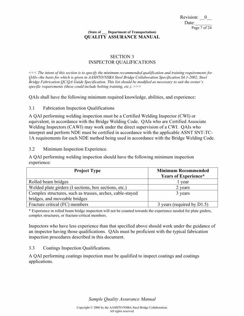
<<< The intent of this section is to specify the minimum recommended qualification and training requirements for QAIs--the basis for which is given in AASHTO/NSBA Steel Bridge Collaboration Specification S4.1-2002, Steel Bridge Fabrication QC/QA Guide Specification. This list should be modified as necessary to suit the owner’s specific requirements (these could include bolting training, etc.). >>> QAIs shall have the following minimum required knowledge, abilities, and experience: 3.1 Fabrication Inspection Qualifications
A QAI performing welding inspection must be a Certified Welding Inspector (CWI) or equivalent, in accordance with the Bridge Welding Code. QAIs who are Certified Associate Welding Inspectors (CAWI) may work under the direct supervision of a CWI. QAIs who interpret and perform NDE must be certified in accordance with the applicable ASNT SNT-TC-1A requirements for each NDE method being used in accordance with the Bridge Welding Code. 3.2 Minimum Inspection Experience.
A QAI performing welding inspection should have the following minimum inspection experience:
Project Type Minimum Recommended Years of Experience*
Rolled beam bridges 1 year Welded plate girders (I sections, box sections, etc.) 2 years Complex structures, such as trusses, arches, cable-stayed bridges, and moveable bridges
3 years
Fracture critical (FC) members 3 years (required by D1.5) * Experience in rolled beam bridge inspection will not be counted towards the experience needed for plate girders, complex structures, or fracture-critical members. Inspectors who have less experience than that specified above should work under the guidance of an inspector having those qualifications. QAIs must be proficient with the typical fabrication inspection procedures described in this document. 3.3 Coatings Inspection Qualifications.
A QAI performing coatings inspection must be qualified to inspect coatings and coatings applications.
Copyright © 2006 by the AASHTO/NSBA Steel Bridge Collaboration.All rights reserved.
Revision: __0__ Date:_______ Page 8 of 24 (State of ___ Department of Transportation) QUALITY ASSURANCE MANUAL
Sample Quality Assurance Manual
3.4 Training Documented training in materials preparation, coatings application, and inspection is suggested for the QC and QA coatings inspectors. Recommended training includes one or more of the following:
• American Institute of Steel Construction (AISC) – Application and Inspection of Sophisticated Coatings
• National Association of Corrosion Engineers (NACE) – International Coating Inspector training and Certification Program Session I: Coating Inspection Training
• Society for Protective Coatings (SSPC) – C-1 Fundamentals of Protective Coatings for Industrial Structures
• National Highway Institute (NHI) – Bridge Coating Inspection Course No. 130079 • Other training programs that are considered acceptable by the Engineer
Copyright © 2006 by the AASHTO/NSBA Steel Bridge Collaboration.All rights reserved.
Revision: __0__ Date:_______ Page 9 of 24 (State of ___ Department of Transportation) QUALITY ASSURANCE MANUAL
Sample Quality Assurance Manual
SECTION 4 RECORDS AND REPORTING
<<< The intent of this section is to recommend the records and reporting required to be kept by QAIs. This section should be modified as necessary to suit the owner’s specific requirements. >>> The QAI shall maintain neat and orderly records for each project. Documentation of the status of fabrication and acceptability of members shall be performed on the forms included in Appendix A. <<< note: specific forms and directions for completing shall be inserted by Owner >>> In addition to completion of the necessary forms, the QAI shall maintain a narrative report for each project, as directed by the Engineer. The narrative report should either be legibly hand-written in a permanently bound book, or be maintained in an electronic log with automatic date and time recording. Record the Fabricator’s activity on the work inspected, including both positive and negative comments, information provided to the Fabricator, and any agreements made. Make entries as soon possible after the events or conversations. Obtain copies of Fabricator generated records such as NDE reports, inspection reports, etc. for the project files and submission to the Engineer as directed. Furnish a written report on a weekly basis to the Engineer as directed. Include those forms and documents required by the Engineer. Number the reports consecutively until completion of the work, with the last report noted “final”. Make notes, letters, faxes, reports, and memoranda clear and brief, and keep them on file. Sign on-site correspondence as its originator. The QAI should maintain verbal communication with the Engineer or his representative as directed. The QAI shall also maintain good relations with the Fabricator’s Quality Control Inspector (QCI). Ensure that both the Engineer and QCI are timely apprised of the QAI’s findings including nonconformances. Written documentation is not a substitute for appropriate dialogue with the Fabricator, but should provide a record of important discussions.
Copyright © 2006 by the AASHTO/NSBA Steel Bridge Collaboration.All rights reserved.
Revision: __0__ Date:_______ Page 10 of 24 (State of ___ Department of Transportation) QUALITY ASSURANCE MANUAL
Sample Quality Assurance Manual
SECTION 5 GENERAL INSTRUCTIONS
<<< The intent of this section is to recommend the general requirements for QAI activities. This list should be modified as necessary to suit the owner’s specific requirements. >>> 5.1 Responsibilities of the QAI Verify that production quality and fabrication processes satisfy contract requirements, including the QCP. Verify that the fabricator has QCI performing inspection functions during all fabrication operations. Perform QA inspections in accordance with this manual and other instructions by the Engineer. Determine extent and frequency of inspection based on the Engineer’s direction. Accept materials that satisfy the Contract requirements. Do not waive items that are contractual obligations of the Fabricator and do not accept material that does not conform to the Contract requirements without the written approval of the Engineer. Do not direct the Fabricator’s personnel. Do not provide suggestions on how to fabricate material. However, the QAI should advise the Fabricator if any operation would, in their opinion, result in noncompliance with the Contract. Direct all official communications to the Fabricator’s quality control. Do not convey directives or personal judgments about overall shop quality or concerns about employee competence to production personnel. Do not divulge a fabricator’s proprietary information to another fabricator. Do not publish, copy or distribute any proprietary information, documents, or forms received from the Fabricator for any purpose other than the contractual needs of the Owner. 5.2 Role of the QAI Perform verification tests, measurements, inspection, or observations to assure that fabricated items conform to the Contract requirements. Although the QAI does not perform QC work, some QA activities may duplicate a portion of QC activity for verification. If there are questions about a requirement or level of quality, contact the Engineer and, if directed, alert the Fabricator. Conduct consistent inspections based on the Contract requirements while providing guidance to the Fabricator concerning interpretation of the plan details and specification mandates. Obtain assistance from the Engineer as needed.
Copyright © 2006 by the AASHTO/NSBA Steel Bridge Collaboration.All rights reserved.
Revision: __0__ Date:_______ Page 11 of 24 (State of ___ Department of Transportation) QUALITY ASSURANCE MANUAL
Sample Quality Assurance Manual
Be familiar with the QCP to better understand the QC operations of the shop. Verify that the shop is conducting operations in accordance with their QCP. 5.3 Interaction with the Fabricator Quality Control Inspector Verify the effectiveness of the QCI’s evaluation of the work. Perform verification inspection after the QCI has completed inspection and testing in accordance with the QCP. However, serious problems noted at any time or stage of fabrication must be immediately pointed out to the QCI. Notify the Engineer if there are any unresolved problems. Though QA inspection may include all aspects of fabrication, the QAI must not supersede QC, which is the responsibility of the Fabricator. If QC is not accomplishing its role, the Engineer and Fabricator must determine the necessary corrections. 5.4 Interaction with the Engineer If the Fabricator’s inquiries involve design questions, material substitutions, alternate fabrication methods, or items that are beyond the authority of the QAI, refer them to the Engineer. 5.5 Interpretation of the Contract Review Contract requirements. If conflicts arise regarding their interpretation or adequacy, seek guidance from the Engineer. Inform the QCI of the results of this discussion. 5.6 Fabrication Observation Establish a proactive pattern of regular and frequent observations during the progress of work to verify satisfactory workmanship without delaying production or missing critical operations. Coordinate verifications with the QCI and accomplish them with minimal additional material handling by the Fabricator and with as little interference with the work in process as possible. Though there are not designated points during fabrication when the suitability of materials must be checked, problems should be discovered and addressed as early as possible.
Copyright © 2006 by the AASHTO/NSBA Steel Bridge Collaboration.All rights reserved.

Revision: __0__ Date:_______ Page 12 of 24 (State of ___ Department of Transportation) QUALITY ASSURANCE MANUAL
Sample Quality Assurance Manual
5.7 Nonconforming Materials and Workmanship A nonconformance is defined as a fabrication error or alteration in the work that does not meet project specifications. Some minor nonconformances can be remedied as provided for in the welding code and project specifications. A typical example of this would include cosmetic weld repairs. Other nonconformances may be more serious and cannot be remedied through simple repair as allowed in the applicable welding code. These types of nonconformances render the affected component unacceptable until such time as the issue is referred to the Engineer for disposition. Typical examples of these nonconformances include, but are not limited to, mis-located holes, incorrect material, final dimensions not in accordance with approved drawings, un-authorized welds, welding without approved welding procedures, and overheating of members. When in doubt regarding the proper disposition method, the QAI should obtain clarification from the Engineer/Owner as necessary. Bring all nonconformance issues to the attention of the Fabricator immediately upon discovery. However, do not direct corrective action. If the Fabricator fails to take corrective action, or continues to operate in an unacceptable manner, immediately notify the Engineer. Verbal notification of nonconformance issues to the fabricator is sometimes sufficient; however serious specification noncompliance issues should always be conveyed in writing to the fabricator and the Engineer. For significant problems, the Fabricator must submit a written proposal concerning the issue, providing documentation of the situation and proposed actions to address the issue. The Fabricator may write directly to the Engineer, Contractor, or both, as directed, and in all cases send a copy to the QAI. When the Engineer’s approval is required for a repair, the inspector shall review and confirm the Fabricator’s proposed methods of repair and description of the existing material conditions. Seek guidance from the Engineer for clarification when necessary. Follow up to verify that all required corrections and applicable NDE have been accomplished. All nonconformances shall be properly resolved before the members can be considered for final acceptance.
Copyright © 2006 by the AASHTO/NSBA Steel Bridge Collaboration.All rights reserved.
Revision: __0__ Date:_______ Page 13 of 24 (State of ___ Department of Transportation) QUALITY ASSURANCE MANUAL
Sample Quality Assurance Manual
SECTION 6 INSPECTION PROCEDURES
<<< The intent of this section is to specify the inspection requirements for QAI activities. This list should be modified as necessary to suit the owner’s specific requirements. >>> 6.1 Mill Test Reports
6.1.1 Verify use of proper materials by reviewing a copy of the MTRs when the material arrives and by monitoring heat numbers during fabrication until the material is joined into a piece-marked item. 6.1.2 Obtain MTRs from the Fabricator in accordance with the Department’s customary practice, including the number of copies and when and to whom MTRs should be submitted. 6.1.3 Verify the following information on MTRs:
• product description (specifications, grade, H or P testing frequency) • chemistry • physical test results, including Charpy V-Notch when applicable • applicable “Buy America” certification requirements • heat number • certification signature (Quality Control Department and Notary, when required)
6.1.4 Do not accept material if the Fabricator cannot furnish appropriate certifications to establish compliance with the required material properties and “Buy America” requirements, if required in the Contract. 6.1.5 Maintain a record of heat number identification for main members. 6.1.6 Accept structural steel based on MTRs. Miscellaneous hardware or other associated products may be accepted based on certifications of compliance. 6.1.7 If the Department requires additional independent physical and/or chemical tests of the material’s properties, then these tests must be performed as soon as practical, and prior to fabrication. If the independent tests indicate noncompliance, do not allow use of the material unless an agreement is reached between the Department and the Fabricator as to its acceptability. Bring such noncompliance to the attention of the QCI for evaluation and disposition. 6.1.8 Verify compliance of MTRs with the requirements of the relevant ASTM or AASHTO specification.
Copyright © 2006 by the AASHTO/NSBA Steel Bridge Collaboration.All rights reserved.
Revision: __0__ Date:_______ Page 14 of 24 (State of ___ Department of Transportation) QUALITY ASSURANCE MANUAL
Sample Quality Assurance Manual
6.2 Inspection of Raw Materials
6.2.1 Verify that the requirements of ASTM A 6 (AASHTO M 160) or ASTM A 20 as applicable, which cover the common requirements for hot-rolled plates, shapes, sheet piling, and bars, are applied, as applicable, for material acceptance inspection and repairing certain surface defects. 6.2.2 Check materials for surface defects and discontinuities, both initially and as material is being worked. Check rolled sections and steel castings for dimensions, straightness, twist, fins, scabs, and rolling defects, prior to fabrication.
6.2.3 Grade of material shall be in accordance with the shop drawing / project requirements. No unauthorized substitutions of material (size or grade) are allowed without the Engineer’s approval.
6.3 Material Cutting Inspection
6.3.1 Check that methods employed for material cutting are allowed by the contract documents specifications. Monitor steel plate during cutting for internal defects or other problems. Check that cutting methods do not produce unacceptable gouges or surface roughness. Check that internal defects or gouges are evaluated and repaired in accordance with the applicable code requirements. Verify that heat numbers are being transferred to cut members.
6.4 Fit-up and Welding Inspection
6.4.1 Review the consumable manufacturer’s certificate of conformance maintained by the Fabricator for all consumables used. If required by the Department, obtain copies for the project file. 6.4.2 If the Department maintains a list of approved electrodes, verify that all consumables used by the Fabricator are on the list. 6.4.3 Monitor these criteria before welding begins:
• approved shop drawings clearly indicate the details of welded joints by welding symbols or sketches. Missing or inappropriate weld details are unacceptable and shall be referred to the Fabricator and Engineer for disposition. Approved drawings must be corrected and approved prior to final acceptance
• appropriate equipment in acceptable condition and periodically calibrated per QCP
• proper functioning of drying and baking ovens
Copyright © 2006 by the AASHTO/NSBA Steel Bridge Collaboration.All rights reserved.
Revision: __0__ Date:_______ Page 15 of 24 (State of ___ Department of Transportation) QUALITY ASSURANCE MANUAL
Sample Quality Assurance Manual
• all welders, welding operators, and tack welders are qualified in accordance with the contract documents
• appropriate welding procedure specifications (WPS) for all detailed joints have been submitted and approved by the Engineer
6.4.4 Monitor these consumable-handling criteria (randomly audit):
• storage, condition, and exposure times of welding consumables • re-drying and recycling limits
6.4.5 Monitor these criteria during welding operations (randomly audit):
• joint details, including root face and opening, bevel angle, and alignment of parts are within appropriate welding code and WPS tolerances
• proper application of extension tabs (run-on and run-off) • cleanliness of surfaces to be welded • proper condition and storage of welding consumables • size, quality, and location of tack welds • the following of approved welding procedure specifications (WPSs) including
amperage, voltage, speed of travel, electrode extension, shielding gas flow rate, and preheat, interpass, and/or post-heat temperatures within applicable welding code and WPS tolerances
• workmanship of individual welders • use of proper repair procedures for fabrication errors, including, when required,
the Engineer’s approval • weld starts and stops, securing and removing run-on and run-off tabs, stopping
short of snipes or plate edges, and ending without craters • for stud welding, ensure test studs are being performed and materials are
acceptable 6.4.6 Monitor these final weld quality criteria:
• size, profile, and contour of fillet and groove welds • defects in welds or parent metal only as permitted by contract documents
code/specifications • accurate interpretation by QCIs for the acceptance or rejection of welds • cleaning and backgouging of welds, including thorough removal of unsound
metal and gouging contamination (copper, carbon). Check proper profile of back-gouged weld for compliance
• overgrinding of weld or adjacent base metal areas so as to reduce material/weld throat
• stud welds exhibit full 360 degree flash or arc welded studs are visually acceptable
Copyright © 2006 by the AASHTO/NSBA Steel Bridge Collaboration.All rights reserved.
Revision: __0__ Date:_______ Page 16 of 24 (State of ___ Department of Transportation) QUALITY ASSURANCE MANUAL
Sample Quality Assurance Manual
6.5 Nondestructive Testing
6.5.1 Review and approve the personnel qualification documentation of those performing NDE for the Fabricator. Assure that all NDE is being scheduled by QCI so that QAI witnessing of the NDE operation is possible. 6.5.2 Periodically witness NDE, review the test results, and verify that reports are complete and legible and completed in a timely manner. 6.5.3 For radiographic testing (RT), conduct the following activities:
• interpret test results in accordance with the contract documents
• verify that final edges may be properly interpreted (if the plate will be cut after RT, the final edge may be within the plate on the RT film)
• verify proper application of edge blocks if necessary (plate edge is final edge
in structure)
• verify that each radiograph represents a unique section or piece by comparing punch marks or other approved methods of marking the work and corresponding marks on the film
• verify that the entire specified area is tested
6.5.4 Periodically observe or conduct, if necessary, ultrasonic testing (UT) to verify the Fabricator’s NDE results. The QAI will determine intervals for observation of verification testing unless otherwise directed by the Engineer.
• verify the calibration of equipment, including horizontal and vertical linearity checks
6.5.5 For magnetic particle testing (MT), conduct the following activities:
• periodically observe the application and interpret the results of MT performed on primary members to verify that they satisfy Bridge Welding Code requirements.
• on ancillary, secondary, or miscellaneous items, periodically observe and interpret
MT when required by the contract documents.
• observe MT when needed to verify visual findings.
Copyright © 2006 by the AASHTO/NSBA Steel Bridge Collaboration.All rights reserved.

Revision: __0__ Date:_______ Page 17 of 24 (State of ___ Department of Transportation) QUALITY ASSURANCE MANUAL
Sample Quality Assurance Manual
• Observe and interpret MT applied to evaluate removal of defects and welded shop repairs for base metal and deficient welds.
• Assure E 709 compliance including assurance that proper lighting levels are
maintained during testing. 6.5.6 For liquid penetrant testing (PT), periodically observe technique and interpret results.
6.6 General Visual Inspection During fabrication the QAI should monitor and spot-check that the work performed by the fabricator meets the contract requirements, including, as a minimum, the following:
• straightness • no unauthorized corrections made by welding or manual thermal cutting • size and quality of punches and dies • proper setup and securing of drilling or reaming templates • bolt hole location, edge distance, and diameter • cylindrical and perpendicular bolt holes • absence of burrs, tears, and chips in bolt holes • thickness of plates, clearances, fitup accuracy, alignment of holes, and proper size of
sections at field connections • shop assembly of girders or other parts required for reaming or drilling of field splice
holes: positioning, securing, match marking members and splice plates, splice plate orientation (flange splice plates’ rolling direction parallel to flanges), fills in assembly, and all plies in contact when assembled
• flatness of flanges at bearing areas • bearing plates and bearing assemblies, including rockers and shoes for structural steel and
expansion joints • proper surface finish and protection of machined surfaces • contact condition of milled bearing surfaces • camber blocking during girder assembly, prior to drilling and QAI acceptance for
disassembly • records of final sweep or camber • inspection and installation of fasteners in the shop • location of stiffeners and connection plates • match-marking of assembled members • preparation of match-mark diagrams • control and use of heat and/or pressure to obtain or correct sweep and camber in
accordance with shop’s QCP, and avoidance of buckles, twists, kinks, or other defects
Copyright © 2006 by the AASHTO/NSBA Steel Bridge Collaboration.All rights reserved.
Revision: __0__ Date:_______ Page 18 of 24 (State of ___ Department of Transportation) QUALITY ASSURANCE MANUAL
Sample Quality Assurance Manual
• legibility and position of erection and shipping marks • no unacceptable twists, bends, kinks, or sweep in finished members • proper number of pieces • small parts properly packaged or otherwise secured against loss or damage in transit • loose pieces fastened in place for shipment • application of rust-preventive material when required, and covering to prevent
contamination of painted surfaces • no cutting apart of welded members without the Engineer's approval
6.7 Dimensional Inspection
6.7.1 Periodically observe laydowns and shop assembly. 6.7.2 Verify the Fabricator’s geometry control methods and measurements. For full or partial shop assemblies, receive the QCI’s signed reports of measurements for the Department’s records. If requested by the Department, photographs should also be included in the QAI’s report.
6.8 Bolting Inspection
6.8.1 Verify the acceptability of fastener components by reviewing MTRs and test reports (including rotational capacity test reports). 6.8.1 If fasteners to be tested by the Department are sampled at the Fabricator’s facility, witness and document sampling of components for fastener assemblies in accordance with the Department’s practice. 6.8.2 Verify that all fasteners are properly stored and segregated. 6.8.3 When fasteners are installed in the shop, ensure that installation and verification testing procedures are properly followed. 6.8.4 Witness the rotational capacity and verification testing for shop-installed high-strength fasteners. 6.8.5 Assure current calibration and functionality of torque wrenches and bolt tension-indicating devices.
6.9 Coating Inspection
6.9.1 When shop sampling is performed:
Copyright © 2006 by the AASHTO/NSBA Steel Bridge Collaboration.All rights reserved.

Revision: __0__ Date:_______ Page 19 of 24 (State of ___ Department of Transportation) QUALITY ASSURANCE MANUAL
Sample Quality Assurance Manual
• coordinate coating sampling in the shop with the Fabricator • conduct sampling as early as possible • witness sampling, including mixing or stirring if required for uniformity • ensure that the required samples are delivered to the Owner in suitable containers
6.9.2 If sampling is not required, check the owner-maintained list of pre-tested, pre-approved coatings to ensure that the actual batches or lots of the paint to be used are acceptable. 6.9.3 If the paint manufacturer sends coating samples directly to the Department for testing and the batches are approved prior to shipment to the Fabricator or jobsite, verify that the batch numbers received correspond to the approved list, and, if applicable, that approval stamps are present. 6.9.4 Prior to coating application, verify the following:
• coating containers are properly marked with a batch number • batches have been properly strained and mixed (note when pot life initiates)
6.9.5 When sampling is required, do not accept coated girders until the Department’s lab accepts the coating. 6.9.6 For coating application inspection, verify the following:
• the shop is checking and documenting environmental conditions and coating is being applied and cured within acceptable conditions
• proper cleaning and surface preparation of base metal prior to application of coating in accordance with manufacturer and/or contract requirements
• adequate curing of each coat as demonstrated by the prescribed test and, when multi-coat systems are used, prior to the application of subsequent coats
• thickness of coating, wet or dry, as specified for each system and type • sufficient drying of coating prior to loading for shipment • absence of dry spray, runs, sags, and other defects • proper coating of inaccessible and limited access areas • proper treatment of faying surfaces
6. 10 Fracture Critical Members
6.10.1 When fabrication is to occur on members designated as Fracture Critical Members (FCMs), the QAI shall become familiar with the requirements of the AASHTO/AWS Fracture Control Plan (Chapter 12 of the Bridge Welding Code).
Copyright © 2006 by the AASHTO/NSBA Steel Bridge Collaboration.All rights reserved.
Revision: __0__ Date:_______ Page 20 of 24 (State of ___ Department of Transportation) QUALITY ASSURANCE MANUAL
Sample Quality Assurance Manual
6.10.2 Check that the base metal complies with the additional requirements for FCMs including fine-grain practice, prohibition of mill repairs, and toughness requirements. 6.10.3 Check that the Fabricator has complied with the more stringent purchasing, storing, and handling requirements for consumables as required by the Fracture Control Plan. 6.10.4 Check that the fabricator complies with the additional fabrication requirements of the Fracture Control Plan including preheating requirements, tack welding limitations, and straightening/cambering/curving requirements. 6.10.5 Confirm that repair welding conforms to the Fracture Control Plan. “Noncritical Repairs” may be preapproved by the Engineer. “Critical Repairs” shall be approved by the Engineer prior to beginning the repair and shall be documented giving details of the type of discontinuity, location, and extent of repair. Verify that all discontinuities to be repaired are covered by the repair procedure. All repair welding shall be monitored and inspected by the QCI and the QAI. 6.10.6 Confirm that the repair is properly made in accordance with the approved repair procedure including additional requirements such as proper preheat, postheat, and nondestructive testing. 6.10.7 Verify that the Fabricator’s NDT Level III is certified by ASNT.
Copyright © 2006 by the AASHTO/NSBA Steel Bridge Collaboration.All rights reserved.
Revision: __0__ Date:_______ Page 21 of 24 (State of ___ Department of Transportation) QUALITY ASSURANCE MANUAL
Sample Quality Assurance Manual
SECTION 7 MATERIAL STORAGE
<<< The intent of this section is to recommend the activities required by the QAI as related to Material Storage during the course of a project. This list should be modified as necessary to suit the owner’s specific requirements. >>> The project schedule may require that completed members be stored at the fabrication shop or other location for a period of time before shipment to the jobsite. Check that the completed members are stored in a manner that will not cause distortion or damage. Check that lifting devices do not damage the material or the coating. The fabricator is responsible for repairing any storage damage prior to shipment to the project.
Copyright © 2006 by the AASHTO/NSBA Steel Bridge Collaboration.All rights reserved.

Revision: __0__ Date:_______ Page 22 of 24 (State of ___ Department of Transportation) QUALITY ASSURANCE MANUAL
Sample Quality Assurance Manual
SECTION 8 LOADING AND SHIPPING
<<< The intent of this section is to recommend activities required by the QAI as related to Loading of material during the course of a project. This list should be modified as necessary to suit the owner’s specific requirements. >>> When all work is complete, conduct a final visual examination of the work. The QCI will provide copies of reports covering the materials to be shipped. Verify that all data are correct. Randomly observe handling and loading of the work to verify that the methods and supports used will prevent significant damage during shipping. Check that damage to coatings during the storage and loading process is properly repaired as appropriate.
Copyright © 2006 by the AASHTO/NSBA Steel Bridge Collaboration.All rights reserved.

Revision: __0__ Date:_______ Page 23 of 24 (State of ___ Department of Transportation) QUALITY ASSURANCE MANUAL
Sample Quality Assurance Manual
SECTION 9 FINAL ACCEPTANCE
<<< The intent of this section is to recommend the requirements of the QAI during the final acceptance of material during the course of a project. This list should be modified as necessary to suit the owner’s specific requirements. >>> When fabrication is complete and the inspection results demonstrate that all contract documents have been satisfied, the materials are conditionally accepted. Confirm that all nonconformances have been properly resolved. Affix the approval stamp or shipping tag on the fabricated piece (or a group of parts bundled or contained together), if required, during preparation of a member/component for shipping, indicating that a representative of the Owner has inspected and accepted the work. Presence of this stamp does not relieve the Contractor of responsibility for proper loading, shipping, final fit, and acceptable final condition of the member or component. If required, notify jobsite personnel or the Owner of the shipment. Submit final report to Owner as directed. If the fabricator elects to ship material that does not meet the contract documents or has unresolved nonconformances, immediately contact the Engineer to notify. Do not affix an approval stamp or tag to the fabricated component(s). If the material is being shipped to a secondary processor such as a galvanizer or coater, then final acceptance/stamping may occur at that location. Coordinate with the Engineer to confirm the method for inspection at the secondary location.
Copyright © 2006 by the AASHTO/NSBA Steel Bridge Collaboration.All rights reserved.
Revision: __0__ Date:_______ Page 24 of 24 (State of ___ Department of Transportation) QUALITY ASSURANCE MANUAL
Sample Quality Assurance Manual
APPENDIX A INSPECTION FORMS
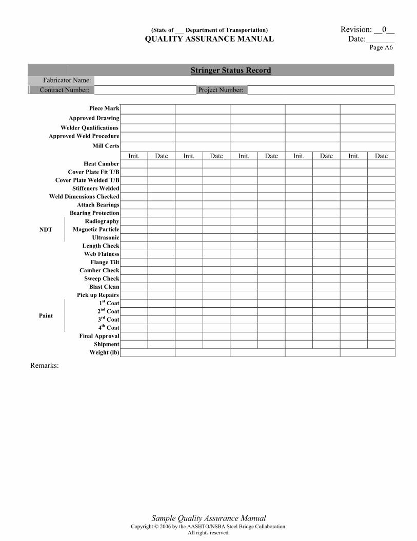
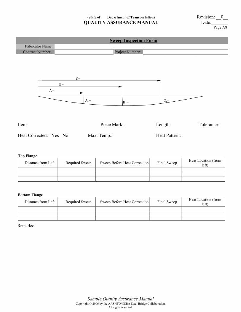
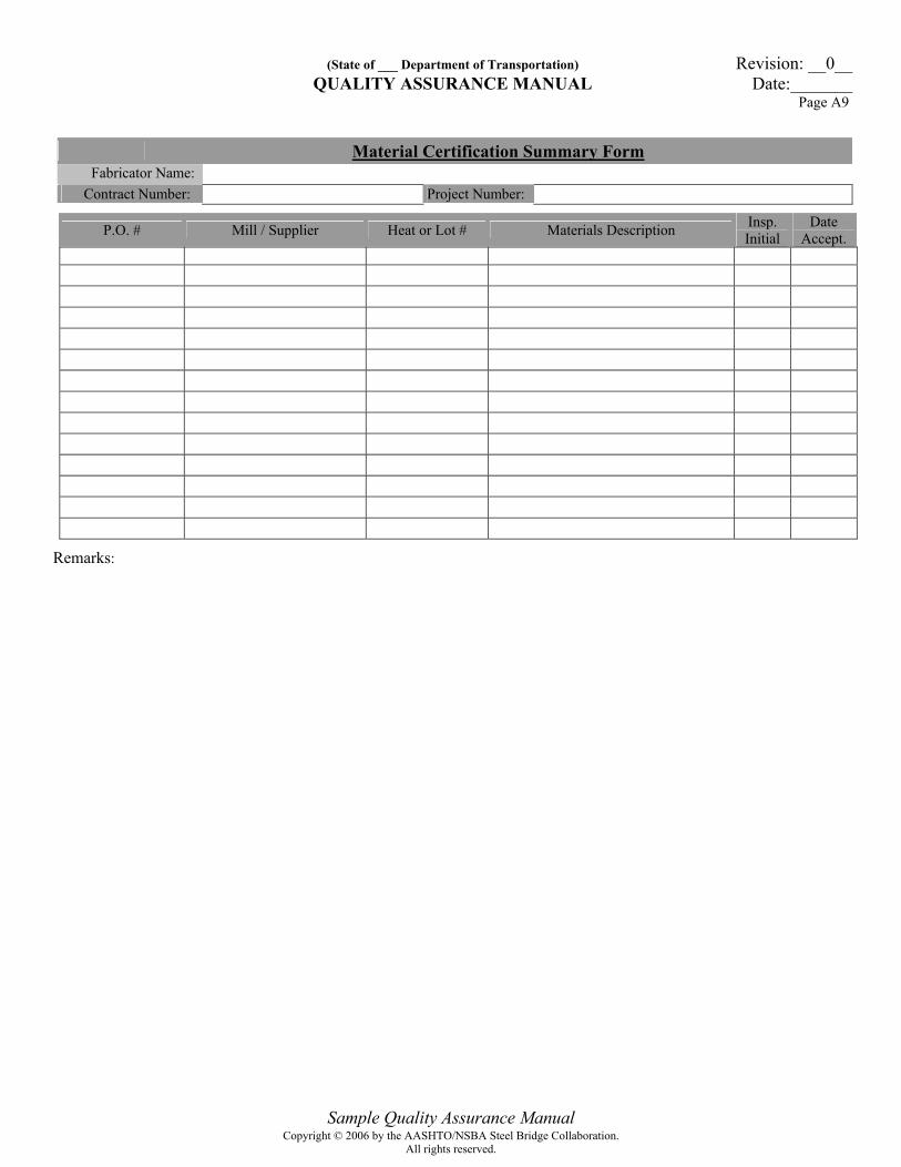
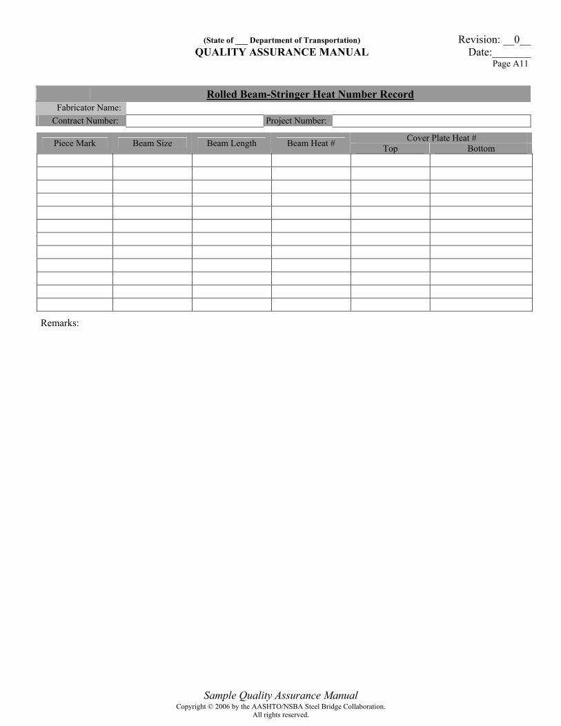
<<<The intent of this section is to include the inspection forms routinely required during the course of a project. This list should be modified as necessary to suit the owner’s specific requirements. >>> Form Page General QA Inspection Forms Bearing Status Record A1 Expansion Dams Status Record A2 Secondary & Miscellaneous Items Status Record A3 Girder Status Record A4 Sign Structure and Pole Status Record A5 Stringer Status Record A6 Camber Inspection Form A7 Sweep Inspection Form A8 Material Certification Summary Form A9 Girder Heat Number Record A10 Rolled Beam-Stringer Heat Number Record A11 Quality Control Repair Summary A12 Bolt Torque Verification Record A13 Galvanizing Inspection Record A14 NDT Inspection Record A15 Paint Inspection Record A16 Project Narrative A17 Standardized Welding Forms Fillet Weld Soundness Test Results Form A18 Procedure Qualification Record Form A19 Weld Procedure Specification Form – D1.1 A20 Weld Procedure Specification Form – D1.5 A21
Copyright © 2006 by the AASHTO/NSBA Steel Bridge Collaboration.All rights reserved.
(State of ___ Department of Transportation) Revision: __0__ QUALITY ASSURANCE MANUAL Date:_______
Page A1
Sample Quality Assurance Manual
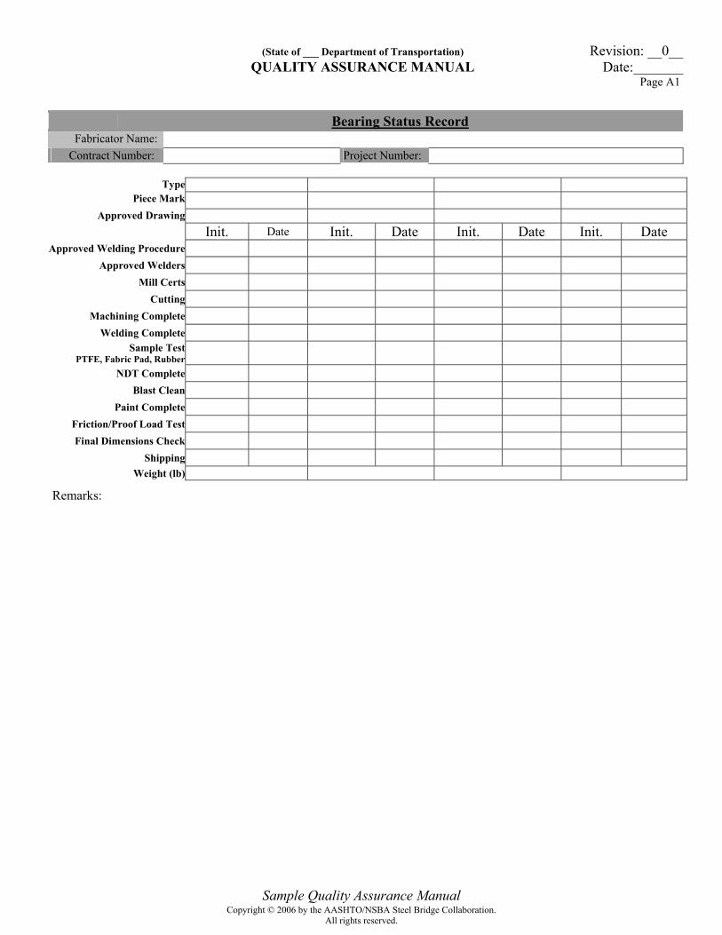
Bearing Status Record Fabricator Name:
Contract Number: Project Number:
Type Piece Mark
Approved Drawing Init. Date Init. Date Init. Date Init. Date
Approved Welding Procedure Approved Welders
Mill Certs Cutting
Machining Complete Welding Complete
Sample Test PTFE, Fabric Pad, Rubber
NDT Complete
Blast Clean Paint Complete
Friction/Proof Load Test Final Dimensions Check
Shipping Weight (lb)
Remarks:
Copyright © 2006 by the AASHTO/NSBA Steel Bridge Collaboration.All rights reserved.

(State of ___ Department of Transportation) Revision: __0__ QUALITY ASSURANCE MANUAL Date:_______
Page A2
Sample Quality Assurance Manual
Expansion Dams Status Record Fabricator Name:
Contract Number: Project Number:
Type Piece Mark
Approved Drawings
Init. Date Init. Date Init. Date Init. Date Init. Date Welder Qualifications
Approved Welding Procedure
Mill Certs
Angles Divisor
Pedestals Cutting
Curb Parapet Welding Complete
Stud Welding Complete Bend Test
Length Elevation
Lug Depth Pedestals
Dimension Check
Contours Certs
Insp.(Car Seal #) Sample
Seal
Approved Sample
Adhesive Approved
Blast Clean Installation of Seal
Depth of Seal Joint Opening
Cleaning of Seal Dye Penetrant
Magnetic Particle NDT Ultrasonic
Painting Complete Galvanizing
Final Approval Shipping
Weight (lb)
Remarks:
Copyright © 2006 by the AASHTO/NSBA Steel Bridge Collaboration.All rights reserved.
(State of ___ Department of Transportation) Revision: __0__ QUALITY ASSURANCE MANUAL Date:_______
Page A3
Sample Quality Assurance Manual
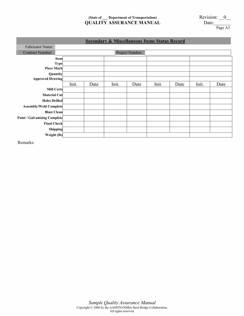
Secondary & Miscellaneous Items Status Record Fabricator Name:
Contract Number: Project Number:
Item Type
Piece Mark Quantity
Approved Drawing Init. Date Init. Date Init. Date Init. Date
Mill Certs Material Cut Holes Drilled
Assembly/Weld Complete Blast Clean
Paint / Galvanizing Complete Final Check
Shipping Weight (lb)
Remarks:
Copyright © 2006 by the AASHTO/NSBA Steel Bridge Collaboration.All rights reserved.
(State of ___ Department of Transportation) Revision: __0__ QUALITY ASSURANCE MANUAL Date:_______
Page A4
Sample Quality Assurance Manual
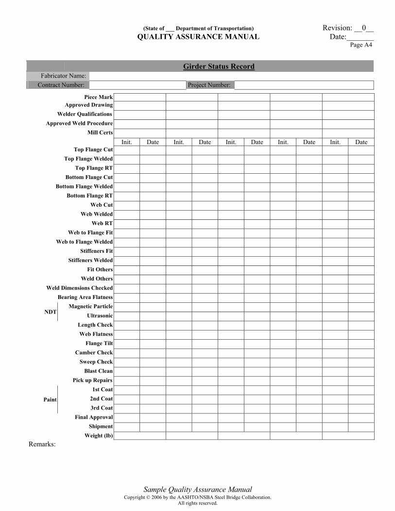
Girder Status Record Fabricator Name:
Contract Number: Project Number:
Piece Mark Approved Drawing
Welder Qualifications Approved Weld Procedure
Mill Certs Init. Date Init. Date Init. Date Init. Date Init. Date
Top Flange Cut Top Flange Welded
Top Flange RT Bottom Flange Cut
Bottom Flange Welded Bottom Flange RT
Web Cut Web Welded
Web RT Web to Flange Fit
Web to Flange Welded Stiffeners Fit
Stiffeners Welded Fit Others
Weld Others Weld Dimensions Checked
Bearing Area Flatness Magnetic Particle
NDT Ultrasonic Length Check Web Flatness
Flange Tilt Camber Check
Sweep Check Blast Clean
Pick up Repairs 1st Coat
2nd Coat Paint 3rd Coat
Final Approval Shipment
Weight (lb) Remarks:
Copyright © 2006 by the AASHTO/NSBA Steel Bridge Collaboration.All rights reserved.

(State of ___ Department of Transportation) Revision: __0__ QUALITY ASSURANCE MANUAL Date:_______
Page A5
Sample Quality Assurance Manual
Sign Structure and Pole Status Record Fabricator Name:
Contract Number: Project Number:
Item Type
Piece Mark Approved Drawing
Init. Date Init. Date Init. Date Init. Date Init. Date Welder Qualifications
Approved Weld Procedure Mill Certs
Cutting Drilling
Welding Complete Weld Dimensions Checked
Dye Penetrant Magnetic Particle
Radiographic NDT
Ultrasonic Galvanizing
Storage Final Approval
Shipping Weight (lb)
Remarks:
Copyright © 2006 by the AASHTO/NSBA Steel Bridge Collaboration.All rights reserved.
(State of ___ Department of Transportation) Revision: __0__ QUALITY ASSURANCE MANUAL Date:_______
Page A6
Sample Quality Assurance Manual
Stringer Status Record Fabricator Name:
Contract Number: Project Number:
Piece Mark Approved Drawing
Welder Qualifications Approved Weld Procedure
Mill Certs Init. Date Init. Date Init. Date Init. Date Init. Date
Heat Camber Cover Plate Fit T/B
Cover Plate Welded T/B Stiffeners Welded
Weld Dimensions Checked Attach Bearings
Bearing Protection Radiography
Magnetic Particle NDT Ultrasonic
Length Check Web Flatness
Flange Tilt Camber Check
Sweep Check Blast Clean
Pick up Repairs 1st Coat
2nd Coat 3rd Coat Paint
4th Coat Final Approval
Shipment Weight (lb)
Remarks:
Copyright © 2006 by the AASHTO/NSBA Steel Bridge Collaboration.All rights reserved.

(State of ___ Department of Transportation) Revision: __0__ QUALITY ASSURANCE MANUAL Date:_______
Page A7
Sample Quality Assurance Manual
Camber Inspection Form Fabricator Name:
Contract Number: Project Number:
Item: Piece Mark: Length: Tolerance:
Heat Corrected: Yes No Max. Temp.: Heat Pattern:
Panel Points B C D Location (From Left End N.S) Required Camber Camber Before Heat Correction Final Camber Heat Location (From Left End N.S)
Remarks: Inspector Name: Inspector Signature:
Copyright © 2006 by the AASHTO/NSBA Steel Bridge Collaboration.All rights reserved.
(State of ___ Department of Transportation) Revision: __0__ QUALITY ASSURANCE MANUAL Date:_______
Page A8
Sample Quality Assurance Manual
Sweep Inspection Form Fabricator Name:
Contract Number: Project Number:
Item: Piece Mark : Length: Tolerance: Heat Corrected: Yes No Max. Temp.: Heat Pattern: Top Flange
Distance from Left Required Sweep Sweep Before Heat Correction Final Sweep Heat Location (from left)
Bottom Flange
Distance from Left Required Sweep Sweep Before Heat Correction Final Sweep Heat Location (from left)
Remarks:
A=
A1=
B=
B1= C1=
C=
Copyright © 2006 by the AASHTO/NSBA Steel Bridge Collaboration.All rights reserved.
(State of ___ Department of Transportation) Revision: __0__ QUALITY ASSURANCE MANUAL Date:_______
Page A9
Sample Quality Assurance Manual
Material Certification Summary Form Fabricator Name:
Contract Number: Project Number:
P.O. # Mill / Supplier Heat or Lot # Materials Description Insp. Initial
Date Accept.
Remarks:
Copyright © 2006 by the AASHTO/NSBA Steel Bridge Collaboration.All rights reserved.

(State of ___ Department of Transportation) Revision: __0__ QUALITY ASSURANCE MANUAL Date:_______
Page A10
Sample Quality Assurance Manual
Girder Heat Number Record Fabricator Name:
Contract Number: Project Number:
Piece Mark Top Flange Web Bottom Flange
Remarks:
Copyright © 2006 by the AASHTO/NSBA Steel Bridge Collaboration.All rights reserved.
(State of ___ Department of Transportation) Revision: __0__ QUALITY ASSURANCE MANUAL Date:_______
Page A11
Sample Quality Assurance Manual
Rolled Beam-Stringer Heat Number Record Fabricator Name:
Contract Number: Project Number:
Cover Plate Heat # Piece Mark Beam Size Beam Length Beam Heat # Top Bottom
Remarks:
Copyright © 2006 by the AASHTO/NSBA Steel Bridge Collaboration.All rights reserved.
(State of ___ Department of Transportation) Revision: __0__ QUALITY ASSURANCE MANUAL Date:_______
Page A12
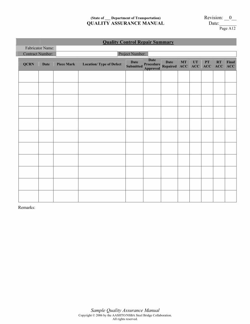
Sample Quality Assurance Manual
Quality Control Repair Summary Fabricator Name:
Contract Number: Project Number:
QCRN Date Piece Mark Location/ Type of Defect Date Submitted
Date Procedure Approved
Date Repaired
MT ACC
UT ACC
PT ACC
RT ACC
Final ACC
Remarks:
Copyright © 2006 by the AASHTO/NSBA Steel Bridge Collaboration.All rights reserved.
(State of ___ Department of Transportation) Revision: __0__ QUALITY ASSURANCE MANUAL Date:_______
Page A13
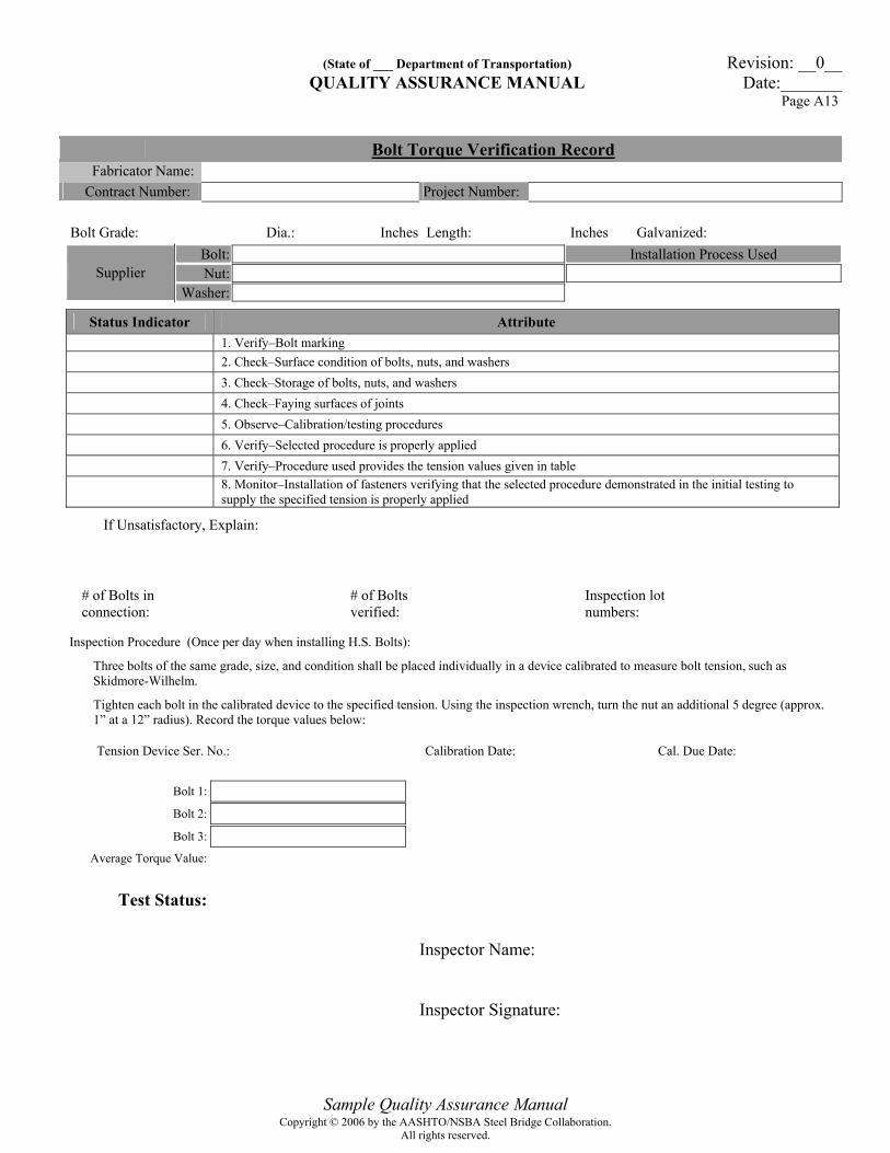
Sample Quality Assurance Manual
Bolt Torque Verification Record Fabricator Name:
Contract Number: Project Number:
Bolt Grade: Dia.: Inches Length: Inches Galvanized:
Bolt: Installation Process Used Nut: Supplier
Washer:
Status Indicator Attribute 1. Verify–Bolt marking 2. Check–Surface condition of bolts, nuts, and washers
3. Check–Storage of bolts, nuts, and washers
4. Check–Faying surfaces of joints
5. Observe–Calibration/testing procedures
6. Verify–Selected procedure is properly applied
7. Verify–Procedure used provides the tension values given in table
8. Monitor–Installation of fasteners verifying that the selected procedure demonstrated in the initial testing to supply the specified tension is properly applied
If Unsatisfactory, Explain:
# of Bolts in connection:
# of Bolts verified:
Inspection lot numbers:
Inspection Procedure (Once per day when installing H.S. Bolts):
Three bolts of the same grade, size, and condition shall be placed individually in a device calibrated to measure bolt tension, such as Skidmore-Wilhelm.
Tighten each bolt in the calibrated device to the specified tension. Using the inspection wrench, turn the nut an additional 5 degree (approx. 1” at a 12” radius). Record the torque values below:
Tension Device Ser. No.: Calibration Date: Cal. Due Date:
Bolt 1:
Bolt 2:
Bolt 3:
Average Torque Value:
Test Status:
Inspector Name: Inspector Signature:
Copyright © 2006 by the AASHTO/NSBA Steel Bridge Collaboration.All rights reserved.

(State of ___ Department of Transportation) Revision: __0__ QUALITY ASSURANCE MANUAL Date:_______
Page A14
Sample Quality Assurance Manual
Galvanizing Inspection Record Fabricator Name:
Contract Number: Project Number:
Type of Inspection (Select one): In-Process Inspection Final Inspection Painted after Galvanizing: Yes No
Item: Type:
Piece Mark: Number of Pieces:
Item Status Remarks Material free from damage:
Material free from grease or other coatings:
Galvanizing procedure reviewed:
Quenching performed:
Chromate treatment allowed:
Cutting / Welding performed by galvanizer:
Material properly handled after coating:
Material stored properly:
Visual appearance acceptable:
Thickness acceptable (use DFT form):
Adhesion visually acceptable:
All welds visually checked for cracks:
Material free from distortion:
Repairs performed per ASTM A780:
Final approval / Ship: Inspector Name: Inspector Signature:
Copyright © 2006 by the AASHTO/NSBA Steel Bridge Collaboration.All rights reserved.
(State of ___ Department of Transportation) Revision: __0__ QUALITY ASSURANCE MANUAL Date:_______
Page A15
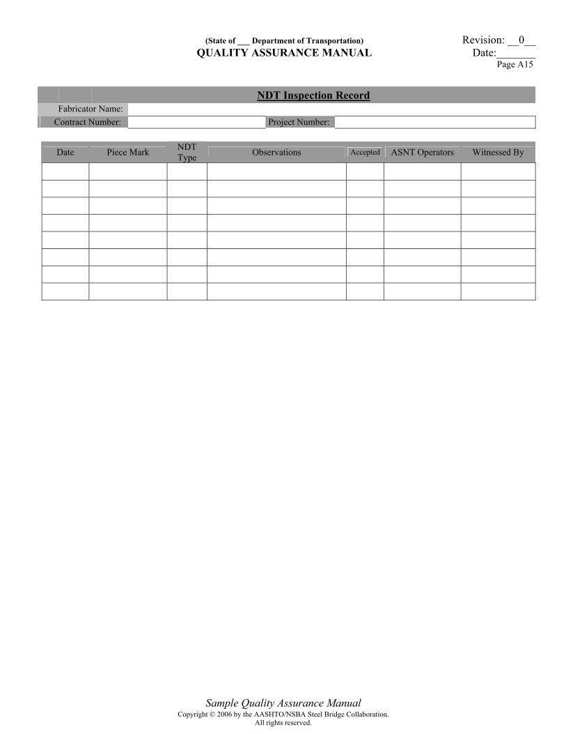
Sample Quality Assurance Manual
NDT Inspection Record Fabricator Name:
Contract Number: Project Number:
Date Piece Mark NDT Type Observations Accepted ASNT Operators Witnessed By
Copyright © 2006 by the AASHTO/NSBA Steel Bridge Collaboration.All rights reserved.

(State of ___ Department of Transportation) Revision: __0__ QUALITY ASSURANCE MANUAL Date:_______
Page A16
Sample Quality Assurance Manual
Paint Inspection Record Fabricator Name:
Contract Number: Project Number:
Piece Mark:
Environmental Conditions for Surface Preparation Date: Time: Dry Bulb Temp.: Wet Bulb Temp.: Relative Humidity: Dew Point: * Surface Temp.: Inspector: Application: Surface finish actual: Surface Profile Actual: Inspector: Date:
Environmental Conditions for Prime Coat Date: Time: Dry Bulb Temp.: Wet Bulb Temp.: Relative Humidity: Dew Point: * Surface Temp.: Inspector: Application: Coating Product: Batch # A Batch # B
Start Date: Time: Stop Date: Time:
Actual DFT Low: High: Avg.: Inspector: Date:
Environmental Conditions for Intermediate Coat Date: Time: Dry Bulb Temp.: Wet Bulb Temp.: Relative Humidity: Dew Point: * Surface Temp.: Inspector: Application: Coating Product: Batch # A Batch # B
Start Date: Time: Stop Date: Time:
Actual DFT Low: High: Avg.: Inspector: Date:
Environmental Conditions for Final Coat Date: Time: Dry Bulb Temp.: Wet Bulb Temp.: Relative Humidity: Dew Point: * Surface Temp.: Inspector: Application: Coating Product: Batch # A Batch # B
Start Date: Time: Stop Date: Time:
Actual DFT Low: High: Avg.: Inspector: Date:
* (must be 5 degrees above dew point)
Copyright © 2006 by the AASHTO/NSBA Steel Bridge Collaboration.All rights reserved.
(State of ___ Department of Transportation) Revision: __0__ QUALITY ASSURANCE MANUAL Date:_______
Page A17
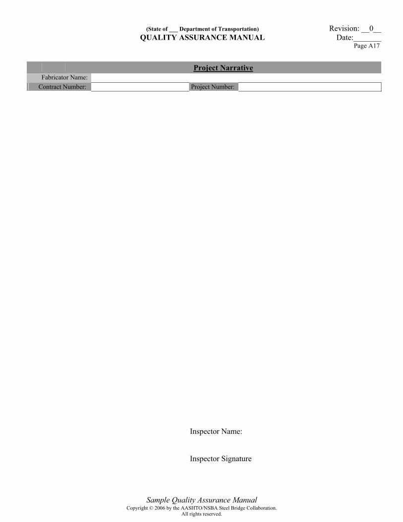
Sample Quality Assurance Manual
Project Narrative Fabricator Name:
Contract Number: Project Number:
Inspector Name: Inspector Signature
Copyright © 2006 by the AASHTO/NSBA Steel Bridge Collaboration.All rights reserved.

Contractor (Fabricator) Prepared by: T1 Thickness T2 Thickness Filler Metal Specification Filler Metal Classification Shielding Gas Flux Mfg. Designation Voltage
(use mean voltage of WPS to be qualified) Amperage/WFS*
(use mean amperage/WFS* of WPS to be qualified) Polarity Position of Welding * wire feed may be used in lieu of current when a correlation curve is provided for the same electrode diameter and electrode extension.
TEST RESULTS (per 5.19.3.1)
Maximum Size Single Pass
Weld Size
Minimum Size Multiple Pass
Weld Size
Weld Size Acceptable
Cracking
Thorough Fusion
Weld Profile per 3.6
Undercut > 1/32 inch
Note: Fillet weld soundness tests are required in addition to groove weld PQRs to qualify fillet welds. A fillet weld macro-tech text shall be made for each WPS and position to be used in construction. Test Plate D shown in Figure 5.8 of AWS D1.5-2002 shall be used. Preparer’s Signature:
(State of ___ Department of Transportation) Revision: __0__QUALITY ASSURANCE MANUAL Date:_______
Page A18
Fillet Weld Soundness Test (FWST) Results AWS D1.5-2002 Section 5.10
FWST No: Date Welded:
Copyright © 2006 by the AASHTO/NSBA Steel Bridge Collaboration.All rights reserved.
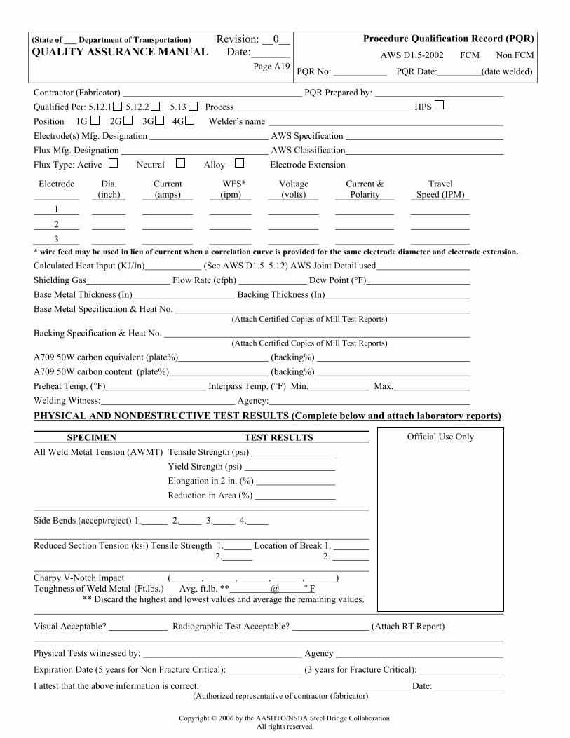
Contractor (Fabricator) PQR Prepared by: Qualified Per: 5.12.1 5.12.2 5.13 Process HPS Position 1G 2G 3G 4G Welder’s name Electrode(s) Mfg. Designation AWS Specification Flux Mfg. Designation AWS Classification Flux Type: Active Neutral Alloy Electrode Extension
Electrode Dia. (inch)
Current (amps)
WFS* (ipm)
Voltage (volts)
Current & Polarity
Travel Speed (IPM)
1 2 3
* wire feed may be used in lieu of current when a correlation curve is provided for the same electrode diameter and electrode extension. Calculated Heat Input (KJ/In) (See AWS D1.5 5.12) AWS Joint Detail used Shielding Gas Flow Rate (cfph) Dew Point (°F) Base Metal Thickness (In) Backing Thickness (In) Base Metal Specification & Heat No. (Attach Certified Copies of Mill Test Reports)
Backing Specification & Heat No. (Attach Certified Copies of Mill Test Reports)
A709 50W carbon equivalent (plate%) (backing%) A709 50W carbon content (plate%) (backing%) Preheat Temp. (°F) Interpass Temp. (°F) Min. Max. Welding Witness: Agency:
PHYSICAL AND NONDESTRUCTIVE TEST RESULTS (Complete below and attach laboratory reports) SPECIMEN TEST RESULTS All Weld Metal Tension (AWMT) Tensile Strength (psi) Yield Strength (psi) Elongation in 2 in. (%) Reduction in Area (%) Side Bends (accept/reject) 1. 2. 3. 4. Reduced Section Tension (ksi) Tensile Strength 1. Location of Break 1. 2. 2. Charpy V-Notch Impact ( , , , , ) Toughness of Weld Metal (Ft.lbs.) Avg. ft.lb. ** @ o F ** Discard the highest and lowest values and average the remaining values.
Visual Acceptable? Radiographic Test Acceptable? (Attach RT Report)
Physical Tests witnessed by: Agency
Expiration Date (5 years for Non Fracture Critical): (3 years for Fracture Critical):
I attest that the above information is correct: Date: (Authorized representative of contractor (fabricator)
(State of ___ Department of Transportation) Revision: __0__QUALITY ASSURANCE MANUAL Date:_______
Page A19
Procedure Qualification Record (PQR) AWS D1.5-2002 FCM Non FCM
PQR No: PQR Date: (date welded)
Official Use Only
Copyright © 2006 by the AASHTO/NSBA Steel Bridge Collaboration.All rights reserved.
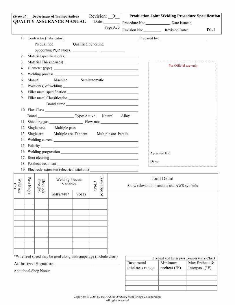
1. Contractor (Fabricator) Prepared by: Prequalified Qualified by testing Supporting PQR No(s).
2. Material specification(s) 3. Material Thickness(es) 4. Diameter (pipe) 5. Welding process 6. Manual Machine Semiautomatic 7. Position(s) of welding 8. Filler metal specification 9. Filler metal Classification
Brand name 10. Flux Class
Brand Type: Active Neutral Alloy 11. Shielding gas Flow rate 12. Single pass Multiple pass 13. Single arc Multiple arc–Tandem Multiple arc–Parallel 14. Welding current 15. Polarity 16. Welding progression 17. Root cleaning 18. Postheat treatment 19. Electrode extension (electrical stickout)
Welding Process Variables
Joint Detail Show relevant dimensions and AWS symbols
Weld size (In)
Pass No(s).
Electrode Size (In)
AMPS/WFS* VOLTS
Travel Speed
(IPM)
*Wire feed speed may be used along with amperage (include chart) Authorized Signature:____________________________ Additional Shop Notes:
(State of ___ Department of Transportation) Revision: __0__QUALITY ASSURANCE MANUAL Date:_______
Page A20
Production Joint Welding Procedure Specification Procedure No: Date Issued:
Revision No: Revision Date: D1.1
For Official use only Approved By: Date:
Preheat and Interpass Temperature Chart Base metal thickness range
Minimum preheat (°F)
Max Preheat & Interpass (°F)
Copyright © 2006 by the AASHTO/NSBA Steel Bridge Collaboration.All rights reserved.

1. Contractor (Fabricator) Prepared by: 2. Non-Fracture Critical Fracture Critical WPS/PQR Expiration date: 3. Qualified in accordance with: 5.11 (prequalified) 5.12.1 5.12.2 5.13 Referenced PQR No(s). ____________ ____________ ____________ ____________ Referenced Fillet Weld Soundness Test No(s). ___________ ____________ 4. Material specification(s) 5. Material Thickness(es) (range) 6. Welding process 7. Manual Machine Semiautomatic 8. Position(s) of welding 9. Filler metal specification 10. Filler metal classification and brand name 11. Flux class & brand
Type: Active Neutral Alloy Shielding gas Flow rate
12. Single pass Multiple pass 13. Single arc Multiple arc – Tandem Multiple arc - Parallel 14. Welding current 15. Polarity 16. Welding progression 17. Root cleaning 18. Postheat treatment 19. Calculated Heat Input (KJ/In) Min Max 20. Electrode extension (electrical stickout)
Welding Process Variables
Joint Detail Show relevant dimensions, AWS Joint Designation and AWS
symbols
Weld size (In)
Pass No(s).
Electrode Size (In)
AMPS/WFS* VOLTS
Travel Speed
(IPM)
*Wire feed speed may be used along with amperage (include chart)
Preparer’s Signature:____________________________ Additional Notes:
(State of ___ Department of Transportation) Revision: __0__QUALITY ASSURANCE MANUAL Date:_______
Page A21
Production Joint Welding Procedure Specification Procedure No: Date Issued:
Revision No: Revision Date: D1.5-2002
For Official use only
Preheat and Interpass Temperature Chart Base metal thickness range
Minimum preheat (°F)
Max Preheat & Interpass (°F)
Copyright © 2006 by the AASHTO/NSBA Steel Bridge Collaboration.All rights reserved.


![[List University Name] Quality Assurance Program ... Assurance Foms/University... · [List University Name] Quality Assurance Program Description Document ... Quality Assurance Program](https://img.pdfslide.us/doc/110x75/5ab8c3d37f8b9aa6018d08ac/list-university-name-quality-assurance-program-assurance-fomsuniversitylist.jpg)