Embed Size (px)
Citation preview

samos® PRO
samos® PRO COMPACT-Gateways
Manual Doc. no. BA000970 Last Update: 03/2020 [10244]

Info
| BA000970 | 03/2020 [10244] 2
INFO
77057547
Copyright This document is copyright-protected. The rights derived from this copyright are reserved for Wie-land Electric. Reproduction of this document or parts of this document is only permissible within the limits of the statutory provision of the Copyright Act. Any modification or abridgment of the document is prohibited without the express written agreement of Wieland Electric.
samos is a registered trademark of WIELAND Electric GmbH
Allen-Bradley, CompactBlock Guard I/O, CompactLogix, ControlFLASH, ControlLogix, DH+, Facto-ryTalk, FLEX, GuardLogix, Kinetix, Logix5000, MicroLogix, PanelBuilder, PanelView, PhaseManager, PLC-2, PLC-3, PLC-5, POINT I/O, POINT Guard I/O, Rockwell Automation, Rockwell Software, RSBiz-Ware, RSFieldbus, RSLinx, RSLogix 5000, RSNetWorx, RSView, SLC, SoftLogix, Stratix, Stratix 2000, Stratix 5700, Stratix 6000, Stratix 8000, Stratix 8300, Studio 5000, Studio 5000 Logix Designer, SynchLink, and Ultra are registered trademarks of Rockwell Automation, Inc.
ControlNet, DeviceNet, and EtherNet/IP are registered trademarks of ODVA, Inc.
TwinCAT is a registered trademark of Beckhoff Automation GmbH.
EtherCAT is a registered trademark and a patented technology licensed by Beckhoff Automation GmbH.
Microsoft, Windows 98, Windows NT, Windows 2000, Windows XP, Windows 7, Windows 8, Windows 8.1, Windows 10 and .NET Framework are registered trademarks of the Microsoft Corporation.
Any other product or trade names listed in this manual are the trademarks or registered trademarks of the respective owners.
Subject to change. Subject to technical changes for reasons of continued development.
Table of Contents
| BA000970 | 03/2020 [10244] 3
TABLE OF CONTENTS
1 About this manual 8
1.1 Function of this document 8
1.2 Scope of validity and applicable documents 9
1.3 Target audience 9
1.4 Information depth 10
1.5 Abbreviations and Definitions 11
1.6 Symbols/icons and writing style/spelling standard used 13
2 Safety 14
2.1 Proper use 14
2.2 Areas of application of the device 14
2.3 Qualified persons 15
2.4 Special obligations of the operator 15
2.5 Environmentally friendly behavior 16
2.5.1 Disposal 16
2.5.2 Sorting of materials 16
3 Product description 17
3.1 Version, compatibility, and features 18
3.2 Equipment variants 20
3.3 Data transferred to the network (network input data sets) 21
3.3.1 Direct gateway output values 25
3.3.2 Module state / input and output values 25
3.3.3 Transmission of data from a second network 26
3.3.4 Configuration test values (CRCs) 26
3.3.5 Error and state information for the modules 27
3.3.6 30
3.4 Data received from the network (network output data sets) 31
4 Installation and basic configuration 32
4.1 Installing/removing 32
4.1.1 Installing modules on hat rail 32
4.1.2 Removing modules from the hat rail 36
4.2 Electrical installation 38
4.3 Initial configuration steps 39
Table of Contents
| BA000970 | 03/2020 [10244] 4
5 Configuration of gateways with samosPLAN 6 40
5.1 The graphical user interface 40
5.1.1 Activating gateway functionality 41
5.1.2 "Gateway" view 42
5.1.3 Layout and content of the tabs 44
5.1.4 "Gateway” and “Properties” docking windows 46
5.2 Function and basic settings 47
5.2.1 Routing 47
5.2.2 Basic settings for the process data 47
5.3 48
5.4 Configuring the gateway output values (tab 1) 49
5.5 Editing the gateway input values (tab 2) 51
5.6 Monitoring process data 53
6 Modbus TCP gateway 54
6.1 Interfaces and operation 54
6.2 Basic configuration – allocation of an IP address 55
6.3 Configuration of the Modbus-TCP interface to the PLC - how the data are transfer-red
56
6.4 Diagnosis and troubleshooting 63
6.5 State bits 65
7 PROFINET IO-Gateway 66
7.1 Interfaces and operation 66
7.2 Basic configuration - Assigning a device name and an IP address 67
7.3 PROFINET configuration of the gateway - how the data are transferred 69
7.4 PROFINET configuration of the gateway - which data are transferred 72
7.5 Diagnostics and troubleshooting 77
7.6 Deactivation of the PROFINET IO function 78
7.7 State bits 78
7.8 Optimizing performance 78

Table of Contents
| BA000970 | 03/2020 [10244] 5
8 EtherNet/IP gateway 79
8.1 Interfaces and operation 79
8.2 Datasheet 79
8.3 Basic setup 80
8.3.1 Basic configuration of PLC 80
8.3.2 Basic configuration of the controller module 84
8.3.3 Configuring the data to PLC 85
8.3.4 Configuring the usage of data from PLC 86
8.4 Supported CIP Objects 87
8.4.1 Identity Object 87
8.4.2 Assembly Object 89
8.4.3 Discrete Input Point Object 90
8.4.4 Discrete Output Point Object 91
8.4.5 Discrete Input Group Object 92
8.4.6 Discrete Output Group Object 93
8.4.7 PCCC Object 94
8.4.7.1 PCCC Telegram Structure 94
8.4.7.2 Word Range Write 95
8.4.7.3 Word Range Read 95
8.4.7.4 Typed Write 96
8.4.7.5 Typed Read 96
8.4.7.6 Protected Typed Logical Read with 2 Address Fields 98
8.4.7.7 Protected Typed Logical Write with 2 Address Fields 98
8.4.7.8 Protected Typed Logical Read with 3 Address Fields 99
8.4.7.9 Protected Typed Logical Write with 3 Address Fields 99
8.4.8 Vendor Object 100
8.4.8.1 Instance 1 100
8.4.8.2 Instance 2 100
8.4.8.3 Instance 3 100
8.4.8.4 Instance 4 100
8.4.8.5 Instance 5 100
8.4.8.6 Instance 6 100
8.4.8.7 Instance 7 101
8.5 Supported Assembly data 104
8.5.1 List of Assembly data 104
8.5.2 Assembly Instances for Logic Output Bytes 106
8.5.2.1 Assembly Instance 37 = 0x25 106
8.5.2.2 Assembly Instances 138 = 0x8a to 141 = 0x8d 106
Table of Contents
| BA000970 | 03/2020 [10244] 6
8.5.3 Assembly Instances for Logic Input Bytes 107
8.5.3.1 Assembly Instance 57 = 0x39 107
8.5.3.2 Assembly Instances 167 = 0xa7 107
8.6 Accessing to CIP objects 109
8.6.1 Explicit Messaging 109
8.6.2 Implicit Messaging 109
8.6.3 Symbolic Addressing 110
8.7 Adjust Performance 111
8.8 Connection with more than one PLC 111
8.9 Diagnostics and troubleshooting 112
8.9.1 Notifications via network 112
8.9.1.1 Explicit Message Connection 112
8.9.1.2 Implicit Message Connection 112
8.9.2 LED States 112
8.9.2.1 MS (Module Status) 112
8.9.2.2 NET (Network Status) 113
8.9.2.3 LINK 114
8.9.2.4 ACT (Activity Status) 114
8.9.3 Diagnostic functions in the configuration software 115
8.10 State bits 116
9 PROFIBUS DP gateway 117
9.1 Interfaces and operation 117
9.2 Projecting 121
9.3 PROFIBUS configuration of the gateway - how the data are transferred 124
9.4 Diagnosis and troubleshooting 131
10 CANopen gateway 133
10.1 Interfaces and operation 133
10.2 CANopen configuration of the gateway - how the data are transferred 138
10.3 CANopen configuration of the gateway - which data are transferred 141
10.4 NMT – network management 142
10.5 SYNC 143
10.6 Emergency 143
10.7 Node guarding 149
10.8 PDO communication 150
10.9 SDO communication 152
10.10 SDO object directory 154
10.11 Guarding protocols 160

Table of Contents
| BA000970 | 03/2020 [10244] 7
10.12 Error objects 162
10.13 CANopen diagnostic examples 165
10.14 Diagnosis and troubleshooting 169
11 EtherCAT Gateway 172
11.1 Interfaces and operation 173
11.2 EtherCAT basics 175
11.3 EtherCAT state machine 177
11.4 Bus topology and cabling 178
11.5 Data transferred into the network 179
11.5.1 Data set 1 180
11.5.2 Data set 2 185
11.5.3 Data set 3 186
11.6 Data received from the network 188
11.7 Configuring an EtherCAT network 189
11.8 EtherCAT configuration of the gateway - how the data are transferred 190
11.9 Diagnostic LEDs on the gateway and troubleshooting 193
12 Technical data 195
12.1 Modbus TCP, PROFINET IO and EtherNet/IP gateway 195
12.2 EtherCAT gateway 195
12.3 PROFIBUS DP 195
12.4 CANopen gateways 196
12.5 Technical data for supply circuit 196
12.6 General technical data 197
12.7 Dimensional drawings 198
12.7.1 Controller module 198
12.7.2 CANopen and PROFIBUS gateways (old housing) 199
12.7.3 EtherCAT gateway 200
13 Order data 201
13.1 Hardware modules and accessories 201
13.2 Modules for contact expansion 203

About this manual
| BA000970 | 03/2020 [10244] 8
ABOUT THIS MANUAL
77306635
Please read this section carefully before you work with these operating instructions and the sa-mosPRO gateways.
Function of this document 77316747
There are three manuals for the samosPRO system with clearly delineated areas of application as well as installation instructions and brief instructions for each module. • This gateway manual describes all samosPRO gateways and their functions in detail. It in-
structs the technical staff of the machine manufacturer or machine operator in the safe installa-tion, configuration, electrical installation, commissioning, operation and maintenance of the samosPRO gateways. This manual does not provide operating instructions for the machine, which incorporates mo-dular samosPRO safety controls and a samosPRO gateway. Information in this regard is provi-ded in the operating instructions for each machine. This manual is only valid in combination with the other samosPRO manuals (see Scope of validi-ty and applicable documents [ch. 1.2, p. 9]).
• The software manual describes the software-supported configuration and parameterization of the samosPRO safety control. In addition, the software manual contains a description of the im-portant diagnostic functions for operation and detailed information for identifying and elimina-ting errors. Use the software manual mainly when configuring, commissioning and operating samosPRO safety controls.
• The Hardware manual describes all of the modules and their functions in detail. Use the hard-ware manual mainly for designing devices.
• Each module contains the installation instructions/brief instructions. These instructions pro-vide information on the fundamental technical specifications of the modules and contain simp-le installation instructions. Use the installation instructions/brief instructions when installing the samosPRO safety control.
This manual contains original operating instructions in accordance with the Machinery Directive.
1
1.1

About this manual
| BA000970 | 03/2020 [10244] 9
Scope of validity and applicable documents 77359627
This manual applies to the following gateway modules: • SP-EN-MOD • SP-EN-PN • SP-EN-IP • SP-PROFIBUS-DP • SP-CANopen • SP-EN-ETC
Table 1: Overview of the samosPRO documentation
Document Title Article number
Software manual samosPLAN 6 software BA000968
Hardware manual samosPRO hardware BA000966
Gateway manual samosPRO gateways BA000970
Operating instruc-tions
SP-COPx (Controller modules of the modular samosPRO safety controller)
BA001119
Operating instruc-tions
SP-SDI/SP-SDIO (Extended modules of the modular samosPRO safety controller)
BA001116
Operating instruc-tions
SP-DIO (Unsafe expansion module of the samosPRO modular safety control)
BA001190
Operating instruc-tions
SP-PROFIBUS-DP (samosPRO-PROFIBUS-DP gateway)
BA001187
Operating instruc-tions
SP-CANopen (samosPRO-CANopen gateway)
BA001188
Operating instruc-tions
SP-EN-ETC (samosPRO EtherCAT gateway)
BA001178
Target audience 77333387
This manual is aimed at the planners, developers and operators of systems that incorporate mo-dular samosPRO safety controls and that want to exchange data with a field bus (controls) via a ga-teway.
It is also aimed at persons commissioning a samosPRO gateway system for the first time or maintai-ning such a system.
1.2
1.3
About this manual
| BA000970 | 03/2020 [10244] 10
Information depth 77345419
This manual contains information about the following topics related to samosPRO gateways: • Installation • Integration into the network • Configuration with the samosPLAN 6 software • Data transmission to and from the network • State information, projection and associated mapping • Item numbers
Important information
ATTENTION
Observing safety information and protective measures Observe the safety information and protective measures for the samosPRO gateways described in this manual.
Downloads are provided on the Internet Also consult our website on the Internet. At the following link http://www.wielandinc.com/, you will find: • the samosPLAN 6 software • The samosPRO manuals available for display and printing in various languages:
– This gateway manual (BA000970) – The hardware manual (BA000966) – The software manual (BA000968)
• The GSD file of the SP-PROFIBUS-DP for PROFIBUS-DP • The EDS file of the SP-CANopen for CANopen
1.4

About this manual
| BA000970 | 03/2020 [10244] 11
Abbreviations and Definitions 77372939
Term Explanation
An element array or an element structure
0b The following are specified in binary format
0x The following are specified in hexadecimal format
Procedure error A procedure error occurs if, in redundant input circuits, the two input signals are not equal. Monitoring of inequality is frequently carried out within a tolerated time window.
ACD Address Collision Detection
ANSI American National Standards Institute, specified character coding
AOI Add On Instruction
AOP Add On Profile
API Actual Packet Interval
AR Application Relation, unique communication relationship in PROFINET IO between the PLC and the device
Attribute Characteristic or property of an object
Bit Data unit with a value of 0 or 1
BOOL Data type specified for CIP devices; stands for a value of 1 byte, in which each of the 8 bits is viewed individually
Byte, BYTE Data unit, representing a sequence of 8 bits; without a plus/minus sign, if not specified
CIP Common Industrial Protocol
Controller module Controller from the samosPRO COMPACT product family
CRC Cyclic Redundancy Check, a type or the result of a hash function for revealing errors in the area of data storage or transmission
Data block A data block contains 2-12 bytes of the relevant data set (depending on the gateway used).
Data set Describes a quantity of associated data, e.g. logic values or system state data. A data set can consist of several data blocks.
I/O Input/output
EPATH Encoded Path, especially for CIP applications
EtherNet/IP Industrially-used Ethernet network, combines standard Ethernet tech-nologies with CIP
Gateway Connection module for industrially-used networks, such as EtherNet/IP, PROFIBUS DB, CANopen, Modbus TCP, etc.
ID An identifier or an identity
Instance The physical representation of an object within a class. It stands for one of several objects within the same object class. (Reference: CIP specifi-cation, version 3.18)
IP Internet protocol
Class A series of objects representing a similar system component. A class is a generalization of the object, a template for defining variables and me-thods. All the objects within a class are identical with regard to function and behavior. However, they may have differing attribute values. (Refe-rence: CIP specification, version 3.18)
LSB Low Significant Byte
MPI Measured Packet Interval; shows the API at the time of measurement
1.5

About this manual
| BA000970 | 03/2020 [10244] 12
Term Explanation
MSB Most Significant Byte
O→T Originator to Target (sender to target device)
ODVA Open Device Vendor Association
PC Personal Computer
PCCC Programmable Controller Communication Command
PLC Programmable Logic Controller
RPI Requested Packet Interval
RX Receive
S/N Serial number
samosPLAN 6 Configuration software for controller modules of type SP-COP. The software can be run on a PC and communicates with the controller modules.
Service Service to be performed Examples: GetAttributeSingle, SetAttributeSingle
SHORT_STRING Data type specified for CIP devices; stands for a character string (1 byte per character, 1 byte length code)
SINT Short integer = 1 byte
SP-COP Safety controller consisting of a controller module of the samosPRO COMPACT product family, as well as optionally connectable expansion gateways and I/O modules.
SP-COP2-ENI Controller module, which is equipped with safety inputs and outputs and gateway functions, amongst other things
PLC Programmable Logic Controller ( PLC)
Stuck-at high Stuck-at high is an error in which the input or output signal gets stuck at On. The causes for a Stuck-at high can be short-circuits to other input and output lines, often called cross-references, or defective switching elements. Stuck-at high errors are discovered through plausibility tests, such as sequence errors in two-channel input circuits or using test pul-ses in input and output circuits.
Stuck-at low Stuck-at low is an error in which the input or output signal gets stuck at Off. The causes of a stuck-at low can be line interruptions in input cir-cuits or defect switching elements. Stuck-at low errors are discovered through plausibility tests and usually do not require immediate error recognition.
T→O Target to Originator
TCP Transmission Control Protocol, Internet standard protocol for the transport layer specified in RFC 793
Test pulses or scan gaps Test pulses or scan gaps are brief switch-offs / interruptions in input and output circuits, which are generated in a targeted manner to detect stuck-at high errors quickly. Test pulses check the switch-off ability of switching elements during operation on an almost continuous basis.
Test pulse error Test pulse errors are undetected test pulses, which lead to a negative test result and thus switch-off of the affected safety circuits.
TX Transmit / Send
UCMM Unconnected Message Manager
UDINT Unsigned double integer = 4 Bytes = 2 Words Data type specified for CIP applications

About this manual
| BA000970 | 03/2020 [10244] 13
Term Explanation
UDP User Datagram Protocol, Internet standard protocol for the transport layer specified in RFC 793
UDT User Defined Type
UINT Unsigned double integer = 2 Bytes = 1 Word Data type specified for CIP applications
USINT Data type specified for CIP applications, which stands for 1 byte without a plus/minus symbol
Symbols/icons and writing style/spelling standard used 68491659
NOTICE These are notes that provide you with information regarding particularities of a device or a soft-ware function.
ATTENTION
Warning! A warning lets you know about specific or potential hazards. It is intended to protect you from accidents and help prevent damage to devices and systems.
• Please read and follow the warnings carefully! Failure to do so may negatively impact the safety functions and cause a hazardous state to oc-cur.
Menus and commands The names of software menus, submenus, options, and commands, selection fields, and windows are written in bold font. Example: Click on Edit in the File menu.
1.6
Safety
| BA000970 | 03/2020 [10244] 14
SAFETY
117623051
This section is intended to support your safety and the safety of the system users. Please read this section carefully before you work with a samosPRO system.
Proper use 117638411
The samosPRO gateways can only be operated in conjunction with a samosPRO safety controller. The firmware version of the connected controller modules must be at least V1.0.0 and the version of the samosPLAN 6 configuration software must be at least 1.0.0.
Basic conditions for use The samosPRO gateways may only be operated under the following conditions: • You are operating the gateway within the specified areas of application.
Further information: Areas of application of the device • You are operating the gateway within the specified operating limits for voltage, temperature,
etc. See the following for further information: Technical data [ch. 12, p. 195]
• You are observing personnel requirements. Further information: Qualified persons [ch. 2.3, p. 15]
• You are observing the special operator obligations. Further information: Special obligations of the operator [ch. 2.4, p. 15]
Improper use Any other use or secondary use is deemed improper and is therefore not permitted. Any warranty claims for resulting damage made against Wieland Electric GmbH shall be deemed invalid. The risk shall be borne solely by the operator.
This also applies to any independent modifications made to the device.
Areas of application of the device 117655435
Do not use for safety-related data
ATTENTION
Do not operate a samosPRO gateway on a safety field bus! The gateway modules are not suitable for operation with a safety field bus! They do not only generate safety-related field bus data (state bytes) for control and diagnostic purposes. They do not support any safety mechanisms that would be required for communication within a safety network.
ATTENTION
Do not use data from a samosPRO gateway for safety-related applications! The samosPRO gateways can be used to integrate non-safety-related data into the logic editor in such a way that the safety function of the samosPRO system may be adversely affected.
• Never integrate a gateway into a samosPRO system without having this source or risk checked by a safety specialist.
Specifications for domestic use If you wish to use the samosPRO system for domestic purposes, you need to take additional steps to prevent the emission of radio frequency interference in limit class B according to EN 55011. Here are some steps you might take: • The use of interference suppressor filters in the supply circuit • Installation in grounded switch cabinets or boxes
2
2.1
2.2
Safety
| BA000970 | 03/2020 [10244] 15
Qualified persons 117630731
A safety control with samosPRO gateways may only be installed, commissioned and maintained by qualified persons.
Qualified persons are those who • have suitable technical training and • have been trained by the machine operator in the operation and applicable safety guidelines
and • have access to the samosPRO system operating instructions and have read them and duly
noted their contents.
Special obligations of the operator 117659659
ATTENTION
The safety instructions and precautions for use of samosPRO gateways must be adhered to. In the event of any other use or any changes to the device – including within the scope of installati-on – this shall nullify any warranty claims with respect to Wieland Electric GmbH.
Duty to provide instruction • This manual must be made available for the operator of the machine on which the samosPRO
system is to be used. The machine operator must be trained by qualified persons and is requi-red to read this manual.
Compliance with standards and regulations • Please follow the standards and guidelines valid in your country when installing and using the
samosPRO gateways. • The national/international legal regulations apply to the installation and use of the modular
samosPRO safety controls as well as to the commissioning and repeated technical testing, par-ticularly the following: – EMC Directive 2014/30/EU – Work Equipment Directive 2009/104/EC – Accident prevention regulations/safety rules
Requirements for electrical installation • The samosPRO gateways do not have their own power supply.
2.3
2.4

Safety
| BA000970 | 03/2020 [10244] 16
Environmentally friendly behavior 77012363
The modular samosPRO safety control and the corresponding modules are designed such that they stress the environment as little as possible. They use only a minimum of power and resources. Make sure that you also carry out work while always considering the environment.
Disposal 77022091
The disposal of unusable or irreparable devices should always be done in accordance with the respectively valid country-specific waste-elimination guidelines (e.g. European Waste Code 16 02 14).
NOTICE We will be happy to help you in disposing of these devices. Simply contact us.
Sorting of materials 77031179
ATTENTION
Important information • The sorting of materials may only be carried out by qualified persons! • Care must be used when disassembling the devices. There is a risk of injuries during this pro-
cess.
Before you can route the devices to the environmentally-friendly recycling process, it is necessary to sort the various materials of the devices. Separate the housing from the rest of the components (particularly from the PC board). Place the separated components into the corresponding recycling containers (see the following
table).
Table 2: Overview of disposal according to components
Components Disposal
Product Housing PC boards, cables, connectors, and electric connecting pieces
Plastic recycling Electronics recycling
Packaging Cardboard, paper
Paper/cardboard recycling
2.5
2.5.1
2.5.2

Product description
| BA000970 | 03/2020 [10244] 17
PRODUCT DESCRIPTION
77437579
samosPRO gateways allow a samosPRO system to transmit non-safety-related data for control and diagnostic purposes to the external field bus system and to receive them.
Important safety information
ATTENTION
Do not operate a samosPRO gateway on a safety field bus! The gateway modules are not suitable for operation with a safety field bus! They do not only generate safety-related field bus data (state bytes) for control and diagnostic purposes. They do not support any safety mechanisms that would be required for communication within a safety network.
Information on the function, configuration and designations
NOTICE Where not otherwise indicated, this manual always considers the data exchanged between the samosPRO system and the relevant network from the point of view of the network master (PLC). Thus data sent to the network from the samosPRO system is termed input data, while data recei-ved from the network is termed output data.
Configuration of samosPRO gateways takes place via the samosPLAN 6 configuration software, using a PC or Notebook connected to the SP-COPx main module via the USB interface or RJ45 Ethernet in-terface.
The safety-related logic of the samosPRO system works independently of the gateway. However, if the system has been configured in such a way that non-safety-related information from the field bus can be integrated into the logic editor, switching off the gateway may result in availability problems.
A samosPRO gateway can only be operated on a samosPRO system. It does not have its own power supply. A maximum of two samosPRO gateways can be operated simultaneously for each system.
The gateway for Modbus TCP, PROFINET IO or EtherNet/IP is integrated into the SP-COP2-ENI con-troller module, while the gateways for Profibus-DP, CANopen or EtherCAT are housed in a 22.5 mm wide installation housing for 35 mm hat rails in accordance with EN 60715.
Order information: Order data [ch. 13, p. 201]
3
Product description
| BA000970 | 03/2020 [10244] 18
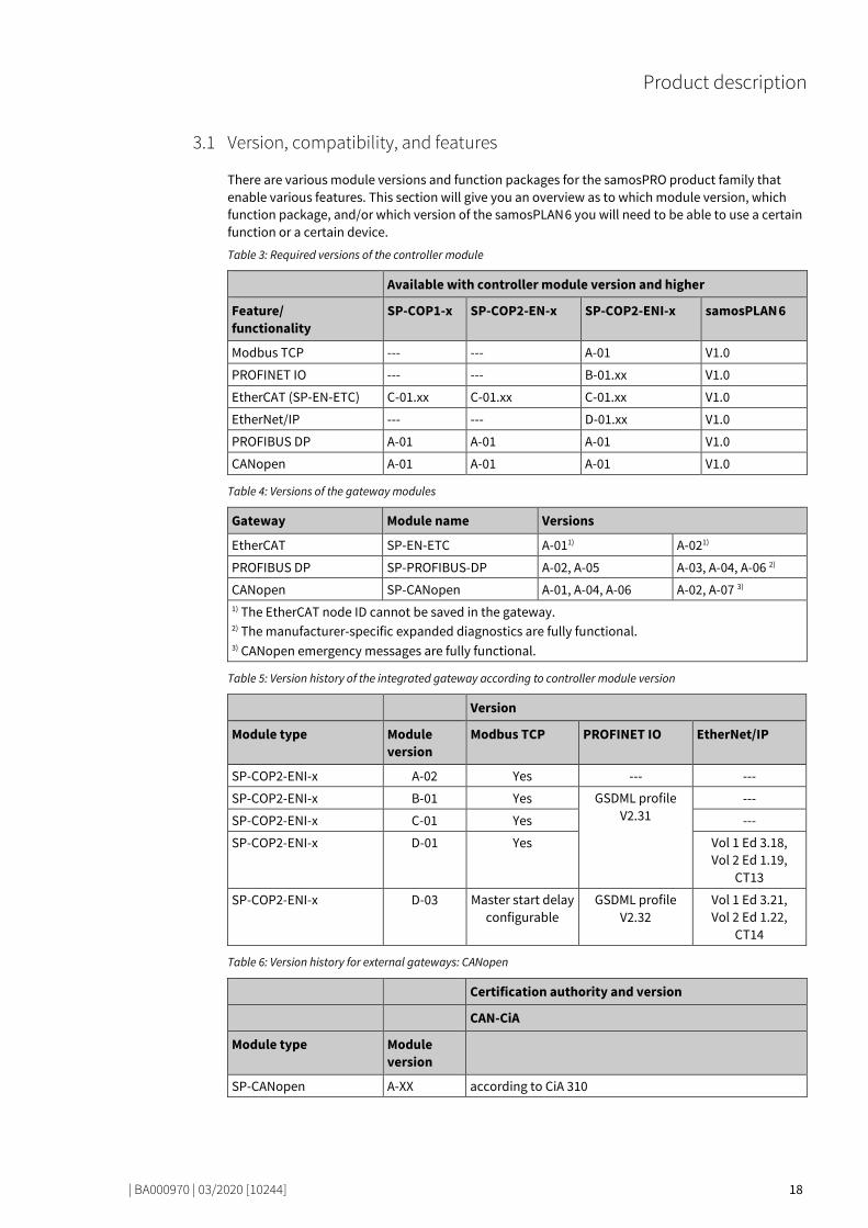
Version, compatibility, and features 77848715
There are various module versions and function packages for the samosPRO product family that enable various features. This section will give you an overview as to which module version, which function package, and/or which version of the samosPLAN 6 you will need to be able to use a certain function or a certain device.
Table 3: Required versions of the controller module
Available with controller module version and higher
Feature/ functionality
SP-COP1-x SP-COP2-EN-x SP-COP2-ENI-x samosPLAN 6
Modbus TCP --- --- A-01 V1.0
PROFINET IO --- --- B-01.xx V1.0
EtherCAT (SP-EN-ETC) C-01.xx C-01.xx C-01.xx V1.0
EtherNet/IP --- --- D-01.xx V1.0
PROFIBUS DP A-01 A-01 A-01 V1.0
CANopen A-01 A-01 A-01 V1.0
Table 4: Versions of the gateway modules
Gateway Module name Versions
EtherCAT SP-EN-ETC A-011) A-021)
PROFIBUS DP SP-PROFIBUS-DP A-02, A-05 A-03, A-04, A-06 2)
CANopen SP-CANopen A-01, A-04, A-06 A-02, A-07 3) 1) The EtherCAT node ID cannot be saved in the gateway. 2) The manufacturer-specific expanded diagnostics are fully functional. 3) CANopen emergency messages are fully functional.
Table 5: Version history of the integrated gateway according to controller module version
Version
Module type Module version
Modbus TCP PROFINET IO EtherNet/IP
SP-COP2-ENI-x A-02 Yes --- ---
SP-COP2-ENI-x B-01 Yes GSDML profile V2.31
---
SP-COP2-ENI-x C-01 Yes ---
SP-COP2-ENI-x D-01 Yes Vol 1 Ed 3.18, Vol 2 Ed 1.19,
CT13
SP-COP2-ENI-x D-03 Master start delay configurable
GSDML profile V2.32
Vol 1 Ed 3.21, Vol 2 Ed 1.22,
CT14
Table 6: Version history for external gateways: CANopen
Certification authority and version
CAN-CiA
Module type Module version
SP-CANopen A-XX according to CiA 310
3.1
Product description
| BA000970 | 03/2020 [10244] 19
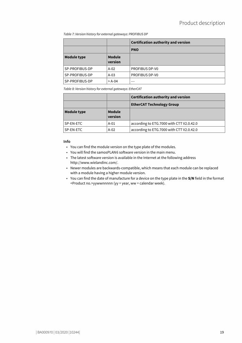
Table 7: Version history for external gateways: PROFIBUS DP
Certification authority and version
PNO
Module type Module version
SP-PROFIBUS-DP A-02 PROFIBUS DP-V0
SP-PROFIBUS-DP A-03 PROFIBUS DP-V0
SP-PROFIBUS-DP > A-04 ---
Table 8: Version history for external gateways: EtherCAT
Certification authority and version
EtherCAT Technology Group
Module type Module version
SP-EN-ETC A-01 according to ETG.7000 with CTT V2.0.42.0
SP-EN-ETC A-02 according to ETG.7000 with CTT V2.0.42.0
Info • You can find the module version on the type plate of the modules. • You will find the samosPLAN 6 software version in the main menu. • The latest software version is available in the Internet at the following address
http://www.wielandinc.com/. • Newer modules are backwards-compatible, which means that each module can be replaced
with a module having a higher module version. • You can find the date of manufacture for a device on the type plate in the S/N field in the format
<Product no.>yywwnnnnn (yy = year, ww = calendar week).
Product description
| BA000970 | 03/2020 [10244] 20
Equipment variants 77455755
There are three samosPRO gateways for various network types.
The Modbus TCP / PROFINET IO and EtherNet/IP gateway of the SP-COP2-ENI controller module or the external SP-EN-ETC gateway are suitable for Ethernet networks. The SP-PROFIBUS-DP gateway and the SP-CANopen gateway are external field bus gateways without an Ethernet function.
ATTENTION
Restrictions for Ethernet connections • The Ethernet connection can only be linked to autonomous networks or demilitarized zones
(DMZ). • The device must never be connected directly to the Internet. • Always use secure data tunnels (VPN) to exchange data via the Internet.
Table 9: Equipment variants and their main characteristics
Gateway Network type Ethernet IP socket interface
SP-EN-MOD Modbus TCP with master and slave operation
Client/Server on TCP Port 502
SP-EN-PN PROFINET IO device UDP ports 34964, 49152
SP-EN-IP EtherNet/IP device TCP port 44818, UDP port 2222
SP-PROFIBUS-DP PROFIBUS DP slave - -
SP-CANopen CANopen slave - -
SP-EN-ETC EtherCAT slave - -
NOTICE You will find the manufacturing date of a device on the type label in the S/N field in the format yywwnnnn (yy = year, ww = calendar week, nnnn = sequential serial number within a calendar week).
3.2
Product description
| BA000970 | 03/2020 [10244] 21
Data transferred to the network (network input data sets) 77477899
Available data The samosPRO gateways can provide the following data: • Process data
– Logic results from the samosPRO safety controller (see Routing table [ch. 5.1.3, p. 44]) – Input values (HIGH/LOW) for all samosPRO input expansion modules in the system – Output values (HIGH/LOW) for all samosPRO input/output expansion modules (see Module
state / input and output values [ch. 3.3.1, p. 25]) – Output data from another network, i.e. data received from a second gateway in the sa-
mosPRO system (see Transmission of data from a second network [ch. 3.3.3, p. 26]) • Diagnostics
– Test values (CRCs): (see Configuration test values (CRCs) [ch. 3.3.4, p. 26]) – Error and state information: Error and state information for the modules [ch. 3.3.5, p. 27]
Data sets The physical modules are not presented as typical hardware modules in the network. Instead, the data provided by the samosPRO system has been arranged in four input data sets. • Data set 1 (max. 50 bytes) contains the process data. It can be compiled with the aid of samos-
PLAN 6. In the form in which it is delivered, the content of data set 1 is preconfigured; it can be freely modified. Details: see table "Overview of input data sets" [ch. 3.3, p. 22] For the SP-PROFIBUS-DP gateway, data set 1 was divided into five input data blocks, with data blocks 1–4 each containing 12 bytes and data block 5 two bytes. For the SP-CANopen gateway, data set 1 was divided into four blocks, each with 8 bytes. You will find more detailed information in the corresponding section for each gateway.
• Data set 2 (32 bytes) contains the test values (CRCs) for the system configuration. See table "Overview of input data sets 1-3 (basic settings for Modbus TCP)" below
• Data set 3 (60 bytes) contains the state and diagnostic data for the various modules, with four (4) bytes per module, with the controller module comprising 3 x 4 bytes. Details: see table "Me-aning of module state bits" [ch. 3.3.5, p. 27]
• Data set 4 (60 bytes) is currently filled with reserved values.
The following table provides an overview of which data sets are provided by which gateway.
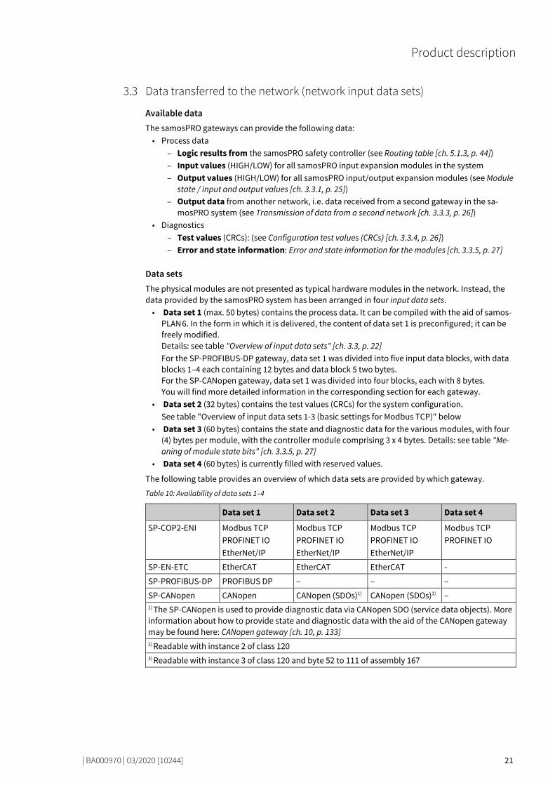
Table 10: Availability of data sets 1–4
Data set 1 Data set 2 Data set 3 Data set 4
SP-COP2-ENI Modbus TCP PROFINET IO EtherNet/IP
Modbus TCP PROFINET IO EtherNet/IP
Modbus TCP PROFINET IO EtherNet/IP
Modbus TCP PROFINET IO
SP-EN-ETC EtherCAT EtherCAT EtherCAT -
SP-PROFIBUS-DP PROFIBUS DP – – –
SP-CANopen CANopen CANopen (SDOs)1) CANopen (SDOs)1) – 1) The SP-CANopen is used to provide diagnostic data via CANopen SDO (service data objects). More information about how to provide state and diagnostic data with the aid of the CANopen gateway may be found here: CANopen gateway [ch. 10, p. 133] 2) Readable with instance 2 of class 120 3) Readable with instance 3 of class 120 and byte 52 to 111 of assembly 167
3.3
Product description
| BA000970 | 03/2020 [10244] 22
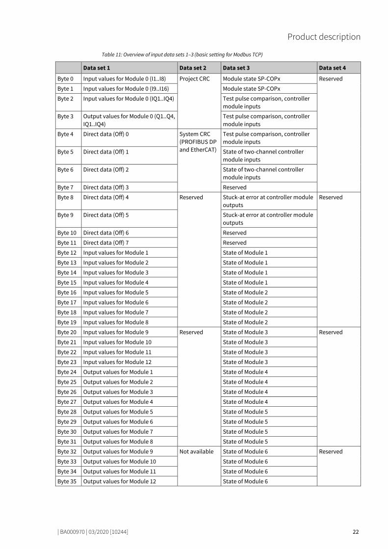
Table 11: Overview of input data sets 1–3 (basic setting for Modbus TCP)
Data set 1 Data set 2 Data set 3 Data set 4
Byte 0 Input values for Module 0 (I1..I8) Project CRC Module state SP-COPx Reserved
Byte 1 Input values for Module 0 (I9..I16) Module state SP-COPx
Byte 2 Input values for Module 0 (IQ1..IQ4) Test pulse comparison, controller module inputs
Byte 3 Output values for Module 0 (Q1..Q4, IQ1..IQ4)
Test pulse comparison, controller module inputs
Byte 4 Direct data (Off) 0 System CRC (PROFIBUS DP and EtherCAT)
Test pulse comparison, controller module inputs
Byte 5 Direct data (Off) 1 State of two-channel controller module inputs
Byte 6 Direct data (Off) 2 State of two-channel controller module inputs
Byte 7 Direct data (Off) 3 Reserved
Byte 8 Direct data (Off) 4 Reserved Stuck-at error at controller module outputs
Reserved
Byte 9 Direct data (Off) 5 Stuck-at error at controller module outputs
Byte 10 Direct data (Off) 6 Reserved
Byte 11 Direct data (Off) 7 Reserved
Byte 12 Input values for Module 1 State of Module 1
Byte 13 Input values for Module 2 State of Module 1
Byte 14 Input values for Module 3 State of Module 1
Byte 15 Input values for Module 4 State of Module 1
Byte 16 Input values for Module 5 State of Module 2
Byte 17 Input values for Module 6 State of Module 2
Byte 18 Input values for Module 7 State of Module 2
Byte 19 Input values for Module 8 State of Module 2
Byte 20 Input values for Module 9 Reserved State of Module 3 Reserved
Byte 21 Input values for Module 10 State of Module 3
Byte 22 Input values for Module 11 State of Module 3
Byte 23 Input values for Module 12 State of Module 3
Byte 24 Output values for Module 1 State of Module 4
Byte 25 Output values for Module 2 State of Module 4
Byte 26 Output values for Module 3 State of Module 4
Byte 27 Output values for Module 4 State of Module 4
Byte 28 Output values for Module 5 State of Module 5
Byte 29 Output values for Module 6 State of Module 5
Byte 30 Output values for Module 7 State of Module 5
Byte 31 Output values for Module 8 State of Module 5
Byte 32 Output values for Module 9 Not available State of Module 6 Reserved
Byte 33 Output values for Module 10 State of Module 6
Byte 34 Output values for Module 11 State of Module 6
Byte 35 Output values for Module 12 State of Module 6

Product description
| BA000970 | 03/2020 [10244] 23
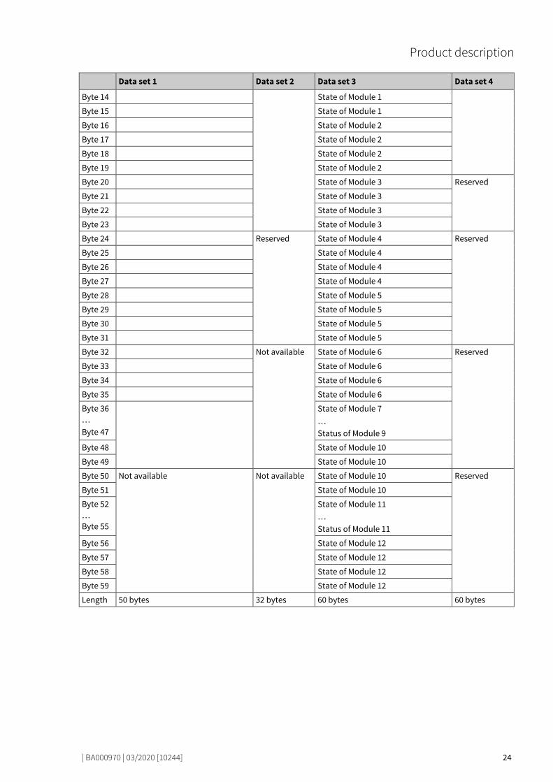
Data set 1 Data set 2 Data set 3 Data set 4
Byte 36 … Byte 47
Not allocated State of Module 7 … Status of Module 9
Byte 48 State of Module 10
Byte 49 State of Module 10
Byte 50 Not available State of Module 10
Byte 51 State of Module 10
Byte 52 … Byte 55
State of Module 11 … Status of Module 11
Byte 56 State of Module 12
Byte 57 State of Module 12
Byte 58 State of Module 12
Byte 59 State of Module 12
Length 50 bytes 32 bytes 60 bytes 60 bytes
NOTICE When two-channel input or output elements have been configured for an I/O module, only the lowest bit constitutes the input or output state (on/off) for the corresponding element. It is re-presented by the tag name of the element. The highest bit represents the state of this in-put/output.
NOTICE The input values in data set 1 do not represent the physical state at the input terminals, but the pre-processed input values that are used for logic processing.
Table 12: Overview of data sets when analog input modules are used (alternative data set 1)
Data set 1 Data set 2 Data set 3 Data set 4
Byte 0 Input values for Module 0 (I1..I8) Project CRC Module state SP-COPx Reserved
Byte 1 Input values for Module 0 (I9..I16) Module state SP-COPx
Byte 2 Input values for Module 0 (IQ1..IQ4) Test pulse comparison, controller module inputs
Byte 3 Output values for Module 0 (Q1..Q4, IQ1..IQ4)
Test pulse comparison, controller module inputs
Byte 4 System CRC (PROFIBUS DP and EtherCAT)
Test pulse comparison, controller module inputs
Byte 5 State of two-channel controller module inputs
Byte 6 State of two-channel controller module inputs
Byte 7 Reserved
Byte 8 Reserved Stuck-at error at controller module outputs
Reserved
Byte 9 Stuck-at error at controller module outputs
Byte 10 Reserved
Byte 11 Reserved
Byte 12 State of Module 1
Byte 13 State of Module 1
Product description
| BA000970 | 03/2020 [10244] 24
Data set 1 Data set 2 Data set 3 Data set 4
Byte 14 State of Module 1
Byte 15 State of Module 1
Byte 16 State of Module 2
Byte 17 State of Module 2
Byte 18 State of Module 2
Byte 19 State of Module 2
Byte 20 State of Module 3 Reserved
Byte 21 State of Module 3
Byte 22 State of Module 3
Byte 23 State of Module 3
Byte 24 Reserved State of Module 4 Reserved
Byte 25 State of Module 4
Byte 26 State of Module 4
Byte 27 State of Module 4
Byte 28 State of Module 5
Byte 29 State of Module 5
Byte 30 State of Module 5
Byte 31 State of Module 5
Byte 32 Not available State of Module 6 Reserved
Byte 33 State of Module 6
Byte 34 State of Module 6
Byte 35 State of Module 6
Byte 36 … Byte 47
State of Module 7 … Status of Module 9
Byte 48 State of Module 10
Byte 49 State of Module 10
Byte 50 Not available Not available State of Module 10 Reserved
Byte 51 State of Module 10
Byte 52 … Byte 55
State of Module 11 … Status of Module 11
Byte 56 State of Module 12
Byte 57 State of Module 12
Byte 58 State of Module 12
Byte 59 State of Module 12
Length 50 bytes 32 bytes 60 bytes 60 bytes
Product description
| BA000970 | 03/2020 [10244] 25
Direct gateway output values 77510539
It is possible to write values directly from the Logic view to a gateway. Four bytes have been reser-ved for this purpose in the basic settings for data set 1; however, up to the total number of 50 bytes of data set 1 may be configured as direct gateway output values. You can obtain additional informa-tion at: Direct gateway output values [ch. 5.4, p. 49].
Module state / input and output values 77520779
The samosPRO gateways can transmit the input and output states of all modules connected to the samosPRO system to the network. Data set 3 contains a non-modifiable configuration. Moreover, data set 1 can be adapted to contain up to 4 bytes of collective state information. Only the input and output values for data set 1 have been predefined and these can be freely adapted. You will find mo-re detailed information in the section on the relevant gateway, as well as in the following section: Configuration of gateways with samosPLAN 6 [ch. 5, p. 40]
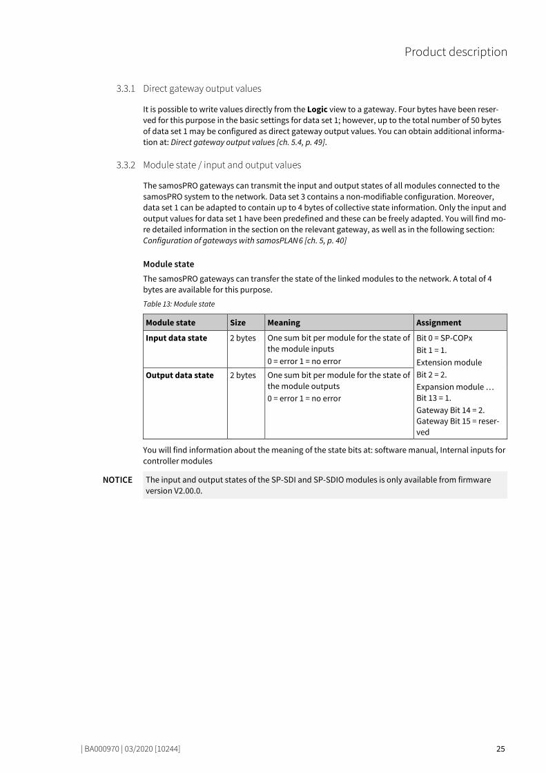
Module state The samosPRO gateways can transfer the state of the linked modules to the network. A total of 4 bytes are available for this purpose.
Table 13: Module state
Module state Size Meaning Assignment
Input data state 2 bytes One sum bit per module for the state of the module inputs 0 = error 1 = no error
Bit 0 = SP-COPx Bit 1 = 1. Extension module Bit 2 = 2. Expansion module … Bit 13 = 1. Gateway Bit 14 = 2. Gateway Bit 15 = reser-ved
Output data state 2 bytes One sum bit per module for the state of the module outputs 0 = error 1 = no error
You will find information about the meaning of the state bits at: software manual, Internal inputs for controller modules
NOTICE The input and output states of the SP-SDI and SP-SDIO modules is only available from firmware version V2.00.0.
3.3.1
3.3.2

Product description
| BA000970 | 03/2020 [10244] 26
Input and output values for the modules • Input values for I/O modules
1 byte for data set 1 is available for every expansion module. The input values show the state of the preliminary evaluation of the I/O module. This corresponds to the state of the element in the controller module logic. The level at the associated terminal cannot be clearly detected from this, as the data may be set to low, irrespectively of the level at the input terminal, by means of the cross-connection detection or two-channel evaluation (e.g. I1-18). When two-channel input elements have been configured for an I/O module, only the lower-value bit represents the pre-evaluation state of the corresponding element (e.g. bit 0 for I1 and I2, bit 2 for I3 and I4, bit 4 for I5 and I6, bit 6 for I7 and I8). The higher-value bit (bit 1, 3, 5 and 7) is used as follows in this case: 0 = error 1 = no error
• Output values for I/O modules 1 byte for data set 1 is available for every module with outputs. The output values indicate the state of the control information from the logic of the controller module for the relevant element of the I/O module. The level of the associated terminals cannot be clearly detected from this, as the output may be switched off via the cross-connection detection or the overload connection function. When two-channel output elements have been configured for an I/O module, only the lower-value bit represents the control information (e.g. bit 0 for Q1 and Q2, bit 2 for Q3 and Q4, bit 4 for Q5 and Q6, bit 6 for Q7 and Q8). The higher-value bit (bit 1, 3, 5 and 7) is not used as follows in this case (low):
Transmission of data from a second network 77547787
If your samosPRO system contains two gateways, it is possible to forward information which the first gateway receives from a network (e.g. from a Modbus PLC) via the second gateway to a second net-work (e.g. to a PROFIBUS master) and vice versa.
Configuration test values (CRCs) 77557259
Data set 2 contains the following configuration check values of the samosPRO system: • Project CRC of the project file created with samosPLAN 6 • System-CRC, uniquely assigned to a module version, consisting of internal software and hard-
ware version
The CRCs are each 4 bytes in length. Data set 2 can be read only.
The project CRC with Modbus/TCP is transmitted in Big Endian format.
3.3.3
3.3.4

Product description
| BA000970 | 03/2020 [10244] 27
Error and state information for the modules 77571083
Data set 3 and 4 contain the state information for the modules that are transferred to the network.
Ten bytes are transmitted for SP-COPx controller module. For each SP-SDI and SP-SDIO I/O module, four bytes are transmitted in the Little Endian format, e.g. as a 32-bit word, with the first byte being placed into the least significant byte of the whole number (extreme left) and the fourth byte into the most significant byte of the whole number (extreme right).
Data sets 3 and 4 cannot be adapted. Module status bits of the controller module SP-COPx The module state bits have the following meaning, if not otherwise indicated:
0 = error
1 = no error
Reserved bits have the value 1
NOTICE You can find an explanation of the technical terms used below here: Abbreviations and Definitions [ch. 1.5, p. 11]
Table 14: Meaning of module state bits of controller module SP-COPx (only for Modbus)
Bit 7 Bit 6 Bit 5 Bit 4 Bit 3 Bit 2 Bit 1 Bit 0
Byte 0 B2 status Collective error fast shut-off
B1 status Configura tion state
A1 status External module state
Internal module state
Reserved
Byte 1 Module state out-put data
Module state of input data
Reserved Reserved IQ3+IQ4 power require-ment 0: Overcur-rent 1: no over-current
IQ1+IQ2 power require-ment 0: Overcur-rent 1: no over-current
Q3+Q4 power require-ment 0: Overcur-rent 1: no over-current
Q1+Q2 power require-ment 0: Overcur-rent 1: no over-current
Byte 2 I8 vs. T2/4 test pulse compari-son
I7 vs. T1/3 test pulse compari-son
I6 vs. T2/4 test pulse compari-son
I5 vs. T1/3 test pulse compari-son
I4 vs. T2/4 test pulse compari-son
I3 vs. T1/3 test pulse compari-son
I2 vs. T2/4 test pulse compari-son
I1 vs. T1/3 test pulse compari-son
Byte 3 I16 vs. T2/4 test pulse compari-son or HW limit fre-quency I16
I15 vs. T1/3 test pulse compari-son or HW limit fre-quency I15
I14 vs. T2/4 test pulse compari-son or HW limit fre-quency I14
I13 vs. T1/3 test pulse compari-son or HW limit fre-quency I13
I12 vs. T2/4 test pulse compari-son
I11 vs. T1/3 test pulse compari-son
I10 vs. T2/4 test pulse compari-son
I9 vs. T1/3 test pulse compari-son
Byte 4 0: Cable break at I16 1: OK or not used
0: Cable break at I15 1: OK or not used
0: Cable break at I14 1: OK or not used
0: Cable break at I13 1: OK or not used
IQ4 vs. T2/4 test pulse compari-son
IQ3 vs. T1/3 test pulse compari-son
IQ2 vs. T2/4 test pulse compari-son
IQ1 vs. T1/3 test pulse compari-son
Byte 5 I15/I16 dual-channel state 0: Error 1: ok or not used
I13/I14 dual-channel state 0: Error 1: ok or not used
I11/I12 dual-channel state 0: Error 1: ok or not used
I9/I10 dual-channel state 0: Error 1: ok or not used
I7/I8 dual-channel state 0: Error 1: ok or not used
I5/I6 dual-channel state 0: Error 1: ok or not used
I3/I4 dual-channel state 0: Error 1: ok or not used
I1/I2 dual-channel state 0: Error 1: ok or not used
3.3.5
Product description
| BA000970 | 03/2020 [10244] 28
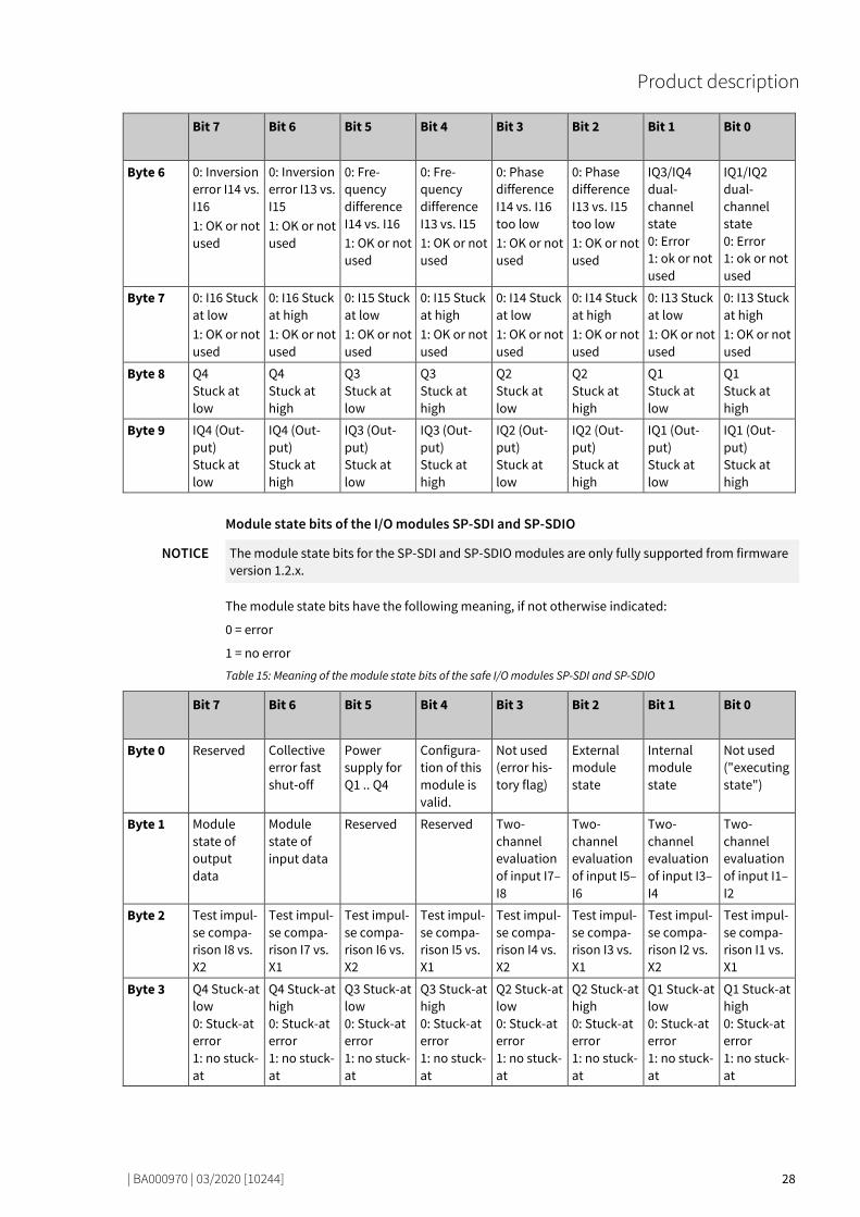
Bit 7 Bit 6 Bit 5 Bit 4 Bit 3 Bit 2 Bit 1 Bit 0
Byte 6 0: Inversion error I14 vs. I16 1: OK or not used
0: Inversion error I13 vs. I15 1: OK or not used
0: Fre-quency difference I14 vs. I16 1: OK or not used
0: Fre-quency difference I13 vs. I15 1: OK or not used
0: Phase difference I14 vs. I16 too low 1: OK or not used
0: Phase difference I13 vs. I15 too low 1: OK or not used
IQ3/IQ4 dual-channel state 0: Error 1: ok or not used
IQ1/IQ2 dual-channel state 0: Error 1: ok or not used
Byte 7 0: I16 Stuck at low 1: OK or not used
0: I16 Stuck at high 1: OK or not used
0: I15 Stuck at low 1: OK or not used
0: I15 Stuck at high 1: OK or not used
0: I14 Stuck at low 1: OK or not used
0: I14 Stuck at high 1: OK or not used
0: I13 Stuck at low 1: OK or not used
0: I13 Stuck at high 1: OK or not used
Byte 8 Q4 Stuck at low
Q4 Stuck at high
Q3 Stuck at low
Q3 Stuck at high
Q2 Stuck at low
Q2 Stuck at high
Q1 Stuck at low
Q1 Stuck at high
Byte 9 IQ4 (Out-put) Stuck at low
IQ4 (Out-put) Stuck at high
IQ3 (Out-put) Stuck at low
IQ3 (Out-put) Stuck at high
IQ2 (Out-put) Stuck at low
IQ2 (Out-put) Stuck at high
IQ1 (Out-put) Stuck at low
IQ1 (Out-put) Stuck at high
Module state bits of the I/O modules SP-SDI and SP-SDIO
NOTICE The module state bits for the SP-SDI and SP-SDIO modules are only fully supported from firmware version 1.2.x.
The module state bits have the following meaning, if not otherwise indicated:
0 = error
1 = no error
Table 15: Meaning of the module state bits of the safe I/O modules SP-SDI and SP-SDIO
Bit 7 Bit 6 Bit 5 Bit 4 Bit 3 Bit 2 Bit 1 Bit 0
Byte 0 Reserved Collective error fast shut-off
Power supply for Q1 .. Q4
Configura-tion of this module is valid.
Not used (error his-tory flag)
External module state
Internal module state
Not used ("executing state")
Byte 1 Module state of output data
Module state of input data
Reserved Reserved Two-channel evaluation of input I7–I8
Two-channel evaluation of input I5–I6
Two-channel evaluation of input I3–I4
Two-channel evaluation of input I1–I2
Byte 2 Test impul-se compa-rison I8 vs. X2
Test impul-se compa-rison I7 vs. X1
Test impul-se compa-rison I6 vs. X2
Test impul-se compa-rison I5 vs. X1
Test impul-se compa-rison I4 vs. X2
Test impul-se compa-rison I3 vs. X1
Test impul-se compa-rison I2 vs. X2
Test impul-se compa-rison I1 vs. X1
Byte 3 Q4 Stuck-at low 0: Stuck-at error 1: no stuck-at
Q4 Stuck-at high 0: Stuck-at error 1: no stuck-at
Q3 Stuck-at low 0: Stuck-at error 1: no stuck-at
Q3 Stuck-at high 0: Stuck-at error 1: no stuck-at
Q2 Stuck-at low 0: Stuck-at error 1: no stuck-at
Q2 Stuck-at high 0: Stuck-at error 1: no stuck-at
Q1 Stuck-at low 0: Stuck-at error 1: no stuck-at
Q1 Stuck-at high 0: Stuck-at error 1: no stuck-at

Product description
| BA000970 | 03/2020 [10244] 29
Module state bits of the SP-DIO I/O module The module state bits have the following meaning if not otherwise indicated; normally only the first byte of the total state is transmitted:
0 = error
1 = no error or reserved
Table 16: Meaning of the module state bits of the SP-DIO expansion module
Bit 7 Bit 6 Bit 5 Bit 4 Bit 3 Bit 2 Bit 1 Bit 0
Byte 0 Reserved Reserved Power supply Y1-Y4 and IY5-IY8
Configura-tion state
Not used (error his-tory flag)
External module state
Internal module state
Not used ("executing state")
Byte 1 Module state out-put data
Module state input data
Reserved Reserved Reserved Reserved Reserved Reserved
Byte 2 Reserved
Byte 3 Reserved
Status bits of analog value modules SP-SAR4, SP-SAC4 and SP-SACR22 Table 17: Meaning of status bits of analog value modules SP-SAR4, SP-SAC4 and SP-SACR22
Bit 7 Bit 6 Bit 5 Bit 4 Bit 3 Bit 2 Bit 1 Bit 0
Byte 0 Reserved Reserved SAC4 and SACR22: Voltage outputs X1…X4
Configu-ration state
Not used (error history flag)
External module state
Internal module state
Not used ("execut-ing sta-te")
Byte 1 Reserved Module state of input data
Reserved Reserved Reserved Reserved Reserved Reserved
Byte 2 Below lower limit of monito-ring ran-ge I4 or Rbx2
Below lower limit of monito-ring ran-ge I3 or Rax1
Below lower limit of monit. range I2 or R2x
Below lower limit of monit. range I1 or R1x
Above upper limit of monit. range I4 or Rbx fn:2
Above upper limit of monit. range I3 or Rax1
Above upper limit of monit. range I2 or R2x
Above upper limit of monit. range I1 or R1x
Byte 3 Open circuit I4 or Rbx2
Open circuit I3 or Rax1
Open circuit I2 or R2x
Open circuit I1 or R1x
Short-circuit I4 or Rbx2
Short-circuit I3 or Rax1
Short-circuit I2 or R2x
Short-circuit I1 or R1x
Bits 1, 2 and 14 are available in the logic editor as corresponding status inputs.

Product description
| BA000970 | 03/2020 [10244] 30
Module state bit of the gateways The module state bits have the following meaning if not otherwise indicated; normally only the first byte of the total state is transmitted:
0 = error
1 = no error
Table 18: Meaning of gateway module state bits
Bit 7 Bit 6 Bit 5 Bit 4 Bit 3 Bit 2 Bit 1 Bit 0
Byte 0 Reserved Module state out-put data
Module state input data
Configura-tion state
Not used (error history flag)
Reserved Internal module state
Not used ("execut-ing state")
Byte 1 Reserved
Byte 2 Reserved
Byte 3 Reserved
Example Module 2 (SP-SDIO) has a short-circuit after high (24 V) at output 3. The following module state is transmitted to the network (only the first 20 of 60 bytes are shown):
Byte address 00 01 02 …
03 11
04 12
05 13
06 14
07 15
08 16
09 17
10 18
11 19
…
Byte 3 0
2 1 1 …
0 11
3 0 2 1 1 2 0 3 3 0 2 1
1 2 0 3 …
Value FF FF FF FF FF FF FF FF EF FB
FF FF FB EF
…
Meaning Status of controller module Status of module 1 (SP-SDIO) State of module 2 (SP-SDIO) …
The first relevant byte for the module 2 error described above is module state byte 0 for module 2. This is byte 11 with the hexadecimal value FB (1111 1011):
Bit # 7 6 5 4 3 2 1 0
Value 1 1 1 1 1 0 1 1
This corresponds to the error message "Summary of bits 0.5 to 0.7 (external error)", byte 0, bit 2 in the following table: "Meaning of module state bits of the secure I/O modules" [ch. 3.3.5, p. 28]
The second relevant byte is the module state byte 3 for module 2. This is byte 08 with the hexadeci-mal value EF (1110 1111):
Bit # 7 6 5 4 3 2 1 0
Value 1 1 1 0 1 1 1 1
This corresponds to the error message "Short circuit monitoring of output 3, short circuit after high", byte 3, bit 4 in the following table: "Meaning of module state bits of the secure I/O modules" [ch. 3.3.5, p. 28]
NOTICE • Reserved (for future use) = static 1 (no state change) • Not used (can be 0 or 1 ), both values occur. • If there is no module, all values - including the reserved values - are set to logical 1.
127677067
Product description
| BA000970 | 03/2020 [10244] 31
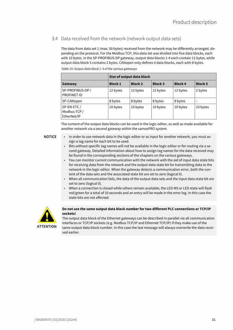
Data received from the network (network output data sets) 77830027
The data from data set 1 (max. 50 bytes) received from the network may be differently arranged, de-pending on the protocol. For the Modbus TCP, this data set was divided into five data blocks, each with 10 bytes. In the SP-PROFIBUS-DP gateway, output data blocks 1-4 each contain 12 bytes, while output data block 5 contains 2 bytes. CANopen only defines 4 data blocks, each with 8 bytes.
Table 19: Output data block 1–5 of the various gateways
Size of output data block
Gateway Block 1 Block 2 Block 3 Block 4 Block 5
SP-PROFIBUS-DP / PROFINET IO
12 bytes 12 bytes 12 bytes 12 bytes 2 bytes
SP-CANopen 8 bytes 8 bytes 8 bytes 8 bytes –
SP-EN-ETC / Modbus TCP / EtherNet/IP
10 bytes 10 bytes 10 bytes 10 bytes 10 bytes
The content of the output data blocks can be used in the logic editor, as well as made available for another network via a second gateway within the samosPRO system.
NOTICE • In order to use network data in the logic editor or as input for another network, you must as-sign a tag name for each bit to be used.
• Bits without specific tag names will not be available in the logic editor or for routing via a se-cond gateway. Detailed information about how to assign tag names for the data received may be found in the corresponding sections of the chapters on the various gateways.
• You can monitor current communication with the network with the aid of input data state bits for receiving data from the network and the output data state bit for transmitting data to the network in the logic editor. When the gateway detects a communication error, both the con-tent of the data sets and the associated state bit are set to zero (logical 0).
• When all communication fails, the data of the output data sets and the input data state bit are set to zero (logical 0).
• When a connection is closed while others remain available, the LED MS or LED state will flash red/green for a total of 10 seconds and an entry will be made in the error log. In this case the state bits are not affected.
ATTENTION
Do not use the same output data block number for two different PLC connections or TCP/IP sockets! The output data block of the Ethernet gateways can be described in parallel via all communication interfaces or TCP/IP sockets (e.g. Modbus TCP/IP and Ethernet TCP/IP) if they make use of the same output data block number. In this case the last message will always overwrite the data recei-ved earlier.
3.4

Installation and basic configuration
| BA000970 | 03/2020 [10244] 32
INSTALLATION AND BASIC CONFIGURATION
77925387
Installing/removing 77933195
Installing modules on hat rail 77138443
ATTENTION
This is only for switch boxes with protection class IP 54 or higher! The samosPRO system is only suitable for installations in a switchbox having at least protection class IP 54.
Notes • Basic safety
Gateways and extension modules may not be removed or added when the operating voltage is switched on.
• Grounding The hat rail must be conductively connected to the protective conductor (PE).
• ESD protection measures Note the suitable ESD protection measures during installation. Failure to do so could result in damage to the internal safety bus.
• Protect connector openings Undertake suitable measures so that no foreign bodies can penetrate connector openings, par-ticularly those for the program removable storage.
• Module width: The modules are placed in a mounting box that is 22.5 mm or 45 mm wide depending on type.
• Quality of hat rail The mounting boxes are suitable for 35 mm hat rails as per EN 60715.
• Sequence of modules: The samosPRO system has the controller module on the far left. The two optional gateways follow directly to the right next to the controller module. The expansion modules only follow thereafter.
• Save space for subsequent model replacement The modules are connected via the plug connection integrated into the housing. Note that the samosPRO modules must be pulled about 10 mm apart before a module replacement so that the corresponding module can be removed from the hat rail.
• Standards to be considered Installation according to EN 50274
4
4.1
4.1.1

Installation and basic configuration
| BA000970 | 03/2020 [10244] 33
Step 1: Installing a controller module Using a screwdriver, pull the snap-on foot outward.
Hang the module on the hat rail.
Important! Make sure that the shielding spring fits correctly. The shielding spring of the module must be placed onto the hat rail so that it is secure and has good electrical contact.
Fold the module onto the hat rail.
Using a screwdriver, move the snap-on foot against the hat rail until the snap-on foot latches in-
to position with an audible click.
Make sure that the module is securely seated on the hat rail.
Attempt to pull the module from the hat rail using slight pressure. If the module stays connec-ted to the hat rail during this test, then the installation is correct.
Installation and basic configuration
| BA000970 | 03/2020 [10244] 34
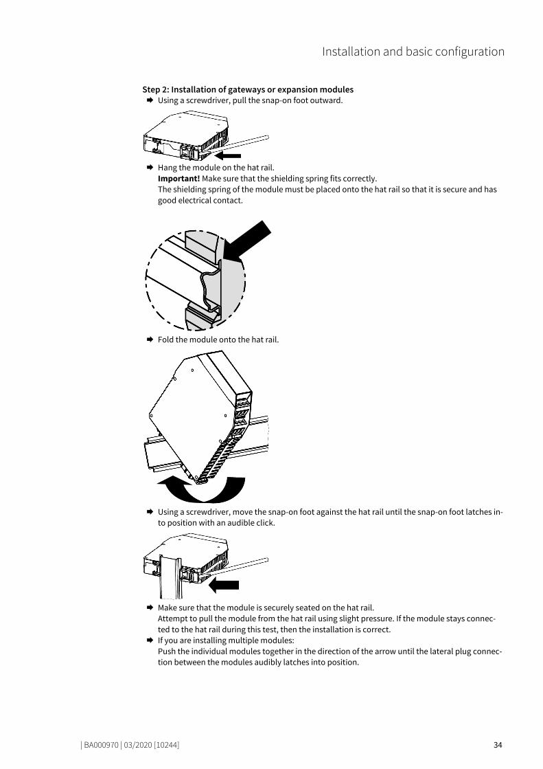
Step 2: Installation of gateways or expansion modules Using a screwdriver, pull the snap-on foot outward.
Hang the module on the hat rail.
Important! Make sure that the shielding spring fits correctly. The shielding spring of the module must be placed onto the hat rail so that it is secure and has good electrical contact.
Fold the module onto the hat rail.
Using a screwdriver, move the snap-on foot against the hat rail until the snap-on foot latches in-
to position with an audible click.
Make sure that the module is securely seated on the hat rail.
Attempt to pull the module from the hat rail using slight pressure. If the module stays connec-ted to the hat rail during this test, then the installation is correct.
If you are installing multiple modules: Push the individual modules together in the direction of the arrow until the lateral plug connec-tion between the modules audibly latches into position.

Installation and basic configuration
| BA000970 | 03/2020 [10244] 35
Install an end terminal into the module furthest to the left and another end terminal into the
module furthest to the right.
After installation Once you have installed the modules, the following steps are required: • Connect the modules electrically. • Configure modules (see: software manual). • Check the installation before first commissioning.

Installation and basic configuration
| BA000970 | 03/2020 [10244] 36
Removing modules from the hat rail 77209227
Step 1: Removing a controller module Deenergize the samosPRO system. Remove plug-in terminals with wiring and remove the end terminal.
If expansion modules or gateways are used:
Slide the controller module in the direction of the arrow until the lateral plug connection is dis-connected.
Unlock the module.
To do this, pull the snap-on foot of the module outward using a screwdriver.
Fold the module away from the hat rail and remove it from the rail.
4.1.2
Installation and basic configuration
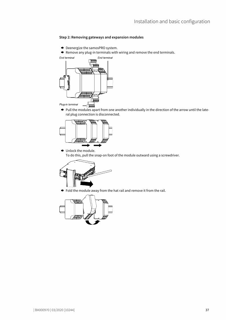
| BA000970 | 03/2020 [10244] 37
Step 2: Removing gateways and expansion modules Deenergize the samosPRO system. Remove any plug-in terminals with wiring and remove the end terminals.
Pull the modules apart from one another individually in the direction of the arrow until the late-
ral plug connection is disconnected.
Unlock the module.
To do this, pull the snap-on foot of the module outward using a screwdriver.
Fold the module away from the hat rail and remove it from the rail.

Installation and basic configuration
| BA000970 | 03/2020 [10244] 38
Electrical installation 77943179
ATTENTION
Switch off the power supply to the system! It is possible for the system to be unexpectedly started while you are connecting the devices.
NOTICE • samosPRO gateways meet EMC conditions as set out in the EN 61000-6-2 specification for use in an industrial environment.
• In order to ensure complete EMC safety, the hat rail must be connected to functional earth (FE).
• The switch box or installation housing for the samosPRO system must meet at least the requi-rements of protection class IP 54.
• Installation according to EN 50274. • Electrical installation as per EN 60204-1. • The external power supply of the devices must be able to bridge a short-term power outage of
20 ms in accordance with EN 60204-1. • The power supply must meet the regulations for low-voltage with safe disconnection (SELV,
PELV) in accordance with EN 60664 and EN 50178 (equipping high-voltage systems with electronic equipment).
• Ensure that all modules of the samosPRO system, the connected protective devices and the power supplies are connected to the same ground connection. The ground of the RS-232 inter-face is internally connected to the ground of the power supply for the controller module (A2).
• Connect the shielding of all field bus and Ethernet cables to functional earth (FE) just before they lead into the switch box.
4.2

Installation and basic configuration
| BA000970 | 03/2020 [10244] 39
Initial configuration steps 77954571
How do you configure gateways? This chapter provides some brief guidelines.
Table 20: Guidelines for gateway configuration
Step Description
1 Establishing a link between the gateway and PC See here for more detailed information: Software manual, chapter "Connecting to the safety controller"
2 Configure gateway You will find detailed information in this regard at the following points in the gate-way manual: • Modbus TCP gateway [ch. 6, p. 54] • PROFINET IO-Gateway [ch. 7, p. 66] • EtherNet/IP gateway [ch. 8, p. 79] • PROFIBUS DP gateway [ch. 9, p. 117] • CANopen gateway [ch. 10, p. 133] • EtherCAT Gateway [ch. 11, p. 172]
3 Transmitting and verifying the configuration See here for more detailed information: Software manual, chapter "Transferring the system configuration"
4.3

Configuration of gateways with samosPLAN 6
| BA000970 | 03/2020 [10244] 40
CONFIGURATION OF GATEWAYS WITH SAMOSPLAN 6
81200651
This chapter gives you an overview of how to configure gateways in samosPLAN 6. It explains • how the graphical user interface is laid out for the gateway configuration insamosPLAN 6, • how you can carry out typical configuration tasks connected to gateways in samosPLAN 6.
NOTICE You will find more detailed information about the graphical user interface of samosPLAN 6 in the Software manual.
The graphical user interface 80966539
You can edit the configuration for gateways in the graphical user interface of samosPLAN 6 in the following windows:
Window Brief explanation
Gateway view
Depending on module configuration, shows two or three tabs with the routing tables and additional gateway func-tionalities. Details: Layout and content of the tabs [ch. 5.1.3, p. 44]
Gateway docking window
Show inputs and outputs available for the gateway confi-guration as a hierarchical tree structure. Details: "Gateway” and “Properties” docking windows [ch. 5.1.4, p. 46]
5
5.1
Configuration of gateways with samosPLAN 6
| BA000970 | 03/2020 [10244] 41
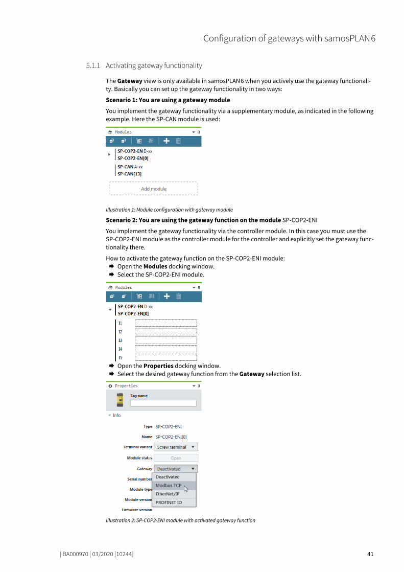
Activating gateway functionality 80990347
The Gateway view is only available in samosPLAN 6 when you actively use the gateway functionali-ty. Basically you can set up the gateway functionality in two ways:
Scenario 1: You are using a gateway module
You implement the gateway functionality via a supplementary module, as indicated in the following example. Here the SP-CAN module is used:
Illustration 1: Module configuration with gateway module
Scenario 2: You are using the gateway function on the module SP-COP2-ENI
You implement the gateway functionality via the controller module. In this case you must use the SP-COP2-ENI module as the controller module for the controller and explicitly set the gateway func-tionality there.
How to activate the gateway function on the SP-COP2-ENI module: Open the Modules docking window. Select the SP-COP2-ENI module.
Open the Properties docking window. Select the desired gateway function from the Gateway selection list.
Illustration 2: SP-COP2-ENI module with activated gateway function
5.1.1
Configuration of gateways with samosPLAN 6
| BA000970 | 03/2020 [10244] 42
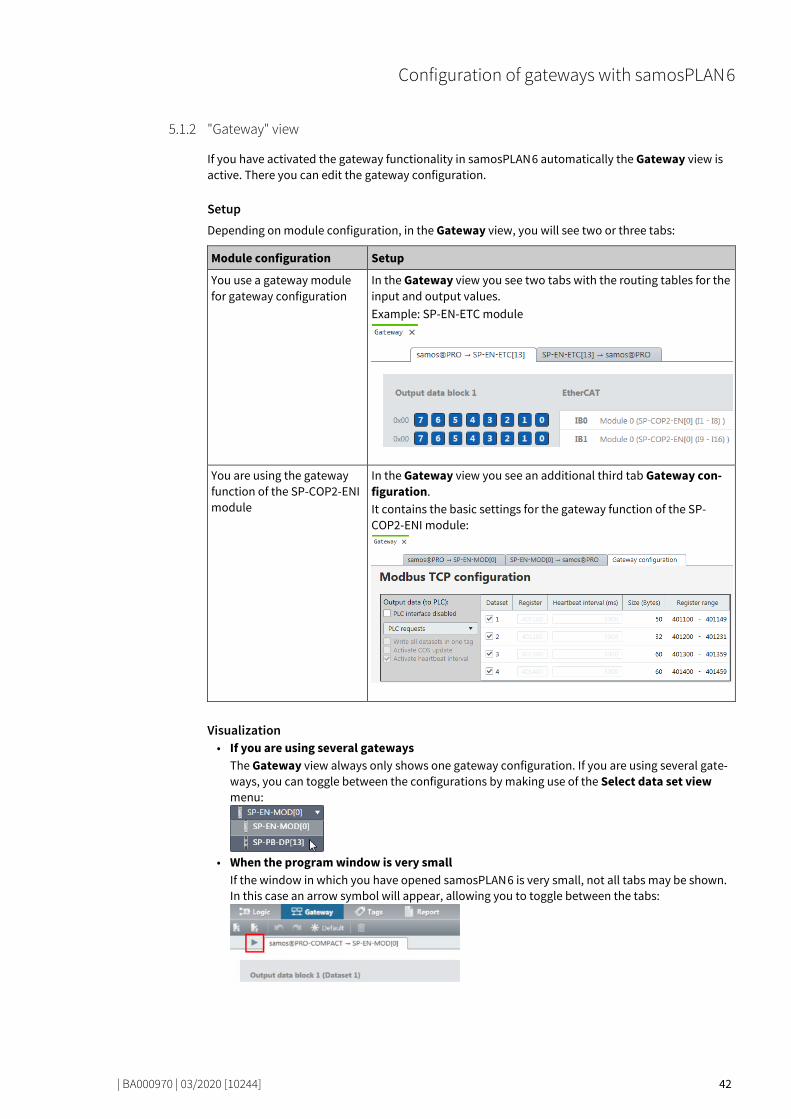
"Gateway" view 81018379
If you have activated the gateway functionality in samosPLAN 6 automatically the Gateway view is active. There you can edit the gateway configuration.
Setup Depending on module configuration, in the Gateway view, you will see two or three tabs:
Module configuration Setup
You use a gateway module for gateway configuration
In the Gateway view you see two tabs with the routing tables for the input and output values. Example: SP-EN-ETC module
You are using the gateway function of the SP-COP2-ENI module
In the Gateway view you see an additional third tab Gateway con-figuration. It contains the basic settings for the gateway function of the SP-COP2-ENI module:
Visualization • If you are using several gateways
The Gateway view always only shows one gateway configuration. If you are using several gate-ways, you can toggle between the configurations by making use of the Select data set view menu:
• When the program window is very small
If the window in which you have opened samosPLAN 6 is very small, not all tabs may be shown. In this case an arrow symbol will appear, allowing you to toggle between the tabs:
5.1.2
Configuration of gateways with samosPLAN 6
| BA000970 | 03/2020 [10244] 43
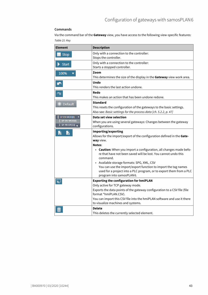
Commands Via the command bar of the Gateway view, you have access to the following view-specific features:
Table 21: Key
Element Description
Only with a connection to the controller: Stops the controller.
Only with a connection to the controller: Starts a stopped controller.
Zoom This determines the size of the display in the Gateway view work area.
Undo This renders the last action undone.
Redo This makes an action that has been undone redone.
Standard This resets the configuration of the gateways to the basic settings. Also see: Basic settings for the process data [ch. 5.2.2, p. 47]
Data set view selection When you are using several gateways: Changes between the gateway configurations.
Importing/exporting Allows for the import/export of the configuration defined in the Gate-way view. Notes: • Caution: When you import a configuration, all changes made befo-
re that have not been saved will be lost. You cannot undo this command.
• Available storage formats: SPG, XML, CSV You can use the import/export function to import the tag names used for a project into a PLC program, or to export them from a PLC program into samosPLAN 6.
Exporting the configuration for hmiPLAN Only active for TCP gateway mode. Exports the data points of the gateway configuration to a CSV file (file format *hmiPLAN.CSV). You can import this CSV file into the hmiPLAN software and use it there to visualize machines and systems.
Delete This deletes the currently selected element.

Configuration of gateways with samosPLAN 6
| BA000970 | 03/2020 [10244] 44
Layout and content of the tabs 81108363
The tabs of the Gateway view contain the following data and features: Tab 1: Routing table with output values (data bytes) Transmission direction: samosPRO COMPACT -> Network/field bus
The mapping is shown in tabular form. Bits which have been used appear on a dark blue back-ground. In online mode, the input data of the relevant gateway is displayed (byte display 0x00 at the start of the relevant line).
Illustration 3: Routing table with output values
Tab 2: Routing table with input values (data bytes) Transmission direction: Network/field bus -> samosPLAN 6
Visualization: as per Tab 1
Illustration 4: Routing table with input values
5.1.3
Configuration of gateways with samosPLAN 6
| BA000970 | 03/2020 [10244] 45
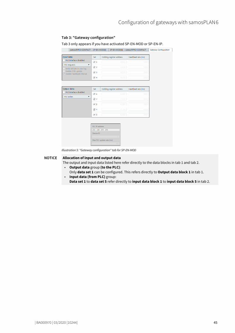
Tab 3: "Gateway configuration" Tab 3 only appears if you have activated SP-EN-MOD or SP-EN-IP.
Illustration 5: "Gateway configuration" tab for SP-EN-MOD
NOTICE Allocation of input and output data The output and input data listed here refer directly to the data blocks in tab 1 and tab 2.
• Output data group (to the PLC): Only data set 1 can be configured. This refers directly to Output data block 1 in tab 1.
• Input data (from PLC) group: Data set 1 to data set 5 refer directly to input data block 1 to input data block 5 in tab 2.
Configuration of gateways with samosPLAN 6
| BA000970 | 03/2020 [10244] 46
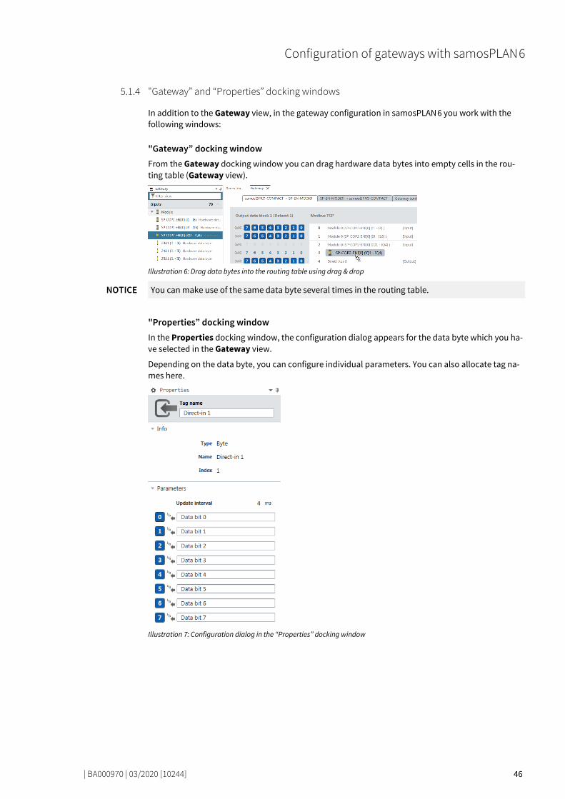
"Gateway” and “Properties” docking windows 81088011
In addition to the Gateway view, in the gateway configuration in samosPLAN 6 you work with the following windows:
"Gateway” docking window From the Gateway docking window you can drag hardware data bytes into empty cells in the rou-ting table (Gateway view).
Illustration 6: Drag data bytes into the routing table using drag & drop
NOTICE You can make use of the same data byte several times in the routing table.
"Properties” docking window In the Properties docking window, the configuration dialog appears for the data byte which you ha-ve selected in the Gateway view.
Depending on the data byte, you can configure individual parameters. You can also allocate tag na-mes here.
Illustration 7: Configuration dialog in the “Properties” docking window
5.1.4

Configuration of gateways with samosPLAN 6
| BA000970 | 03/2020 [10244] 47
Function and basic settings 81134347
Routing 81142283
The process diagram, transferred to the network from the samosPRO gateway, comprises the opera-ting data (e.g. logic results, state of inputs and outputs) and the diagnostic data (e.g. module status, CRCs). This data have been arranged in 4 data sets.
Table 22: Content of data sets 1–4
Data set Content Size Configurable
1 Process data 50 bytes Yes
2 CRCs 32 bytes No
3 State and diagnosis 60 bytes No
4 Reserved 60 bytes No
The process data in Data Set 1 may consist of up to 50 bytes, irrespective of the network protocol used. These 50 bytes have been divided into one or several data blocks, depending on the network protocol. Detailed information about the modularization of the data sent to the network may be found in the section on the relevant gateway and in the following table: "Preset configuration for process data transmitted in the network" [ch. 5.2.2, p. 47]
The content of data set 1 has been pre-configured with the addition of a gateway module or a gate-way function, but can be freely configured with a granularity of 1 byte (see Basic settings for process data [ch. 5.2.2, p. 47] and Configuring the gateway output values (tab 1) [ch. 5.4, p. 49]).
The diagnostic data in data sets 2-4 depends on the network protocol used and is described in the chapter on the relevant gateway.
Basic settings for the process data 81160331
After the addition of the gateway, the process data is pre-configured. Depending on the gateway used, this data is divided into several data blocks.
The following table provides an overview of which bytes have been allocated to the preset configu-ration and how the data at the various gateways are modularized.
Table 23: Preset configuration for the process data transmitted in the network
Modbus TCP PROFIBUS DP
Byte Preset allocation Initial data set Preset allocation Initial data block
0 Input values for Module 0 (I1..I8) #1 (50 bytes)
Input values for Module 0 (I1..I8) #1 (12 bytes) 1 Input values for Module 0 (I9..I16) Input values for Module 0 (I9..I16)
2 Input values for Module 0 (IQ1..IQ4) Input values for Module 0 (IQ1..IQ4)
3 Output values for Module 0 (Q1..Q4,IQ1-IQ4)
Output values for Module 0 (Q1..Q4,IQ1-IQ4)
4 Direct data (Off) 0 Direct data (Off) 0
5 Direct data (Off) 1 Direct data (Off) 1
6 Direct data (Off) 2 Direct data (Off) 2
7 Direct data (Off) 3 Direct data (Off) 3
8 Direct data (Off) 4 Direct data (Off) 4
9 Direct data (Off) 5 Direct data (Off) 5
10 Direct data (Off) 6 Direct data (Off) 6
11 Direct data (Off) 7 Direct data (Off) 7
5.2
5.2.1
5.2.2

Configuration of gateways with samosPLAN 6
| BA000970 | 03/2020 [10244] 48
Modbus TCP PROFIBUS DP
Byte Preset allocation Initial data set Preset allocation Initial data block
12 Inputs for Module 1 Continued #1 (50 bytes)
Inputs for Module 1 #2 (12 bytes) 13 Inputs for Module 2 Inputs for Module 2
14 Inputs for Module 3 Inputs for Module 3
15 Inputs for Module 4 Inputs for Module 4
16 Inputs for Module 5 Inputs for Module 5
17 Inputs for Module 6 Inputs for Module 6
18 Inputs for Module 7 Inputs for Module 7
19 Inputs for Module 8 Inputs for Module 8
20 Inputs for Module 9 Inputs for Module 9
21 Inputs for Module 10 Inputs for Module 10
22 Inputs for Module 11 Inputs for Module 11
23 Inputs for Module 12 Inputs for Module 12
24 Outputs for Module 1 Continued #1 (50 bytes)
Outputs for Module 1 #3 (12 bytes) 25 Outputs for Module 2 Outputs for Module 2
26 Outputs for Module 3 Outputs for Module 3
27 Outputs for Module 4 Outputs for Module 4
28 Outputs for Module 5 Outputs for Module 5
29 Outputs for Module 6 Outputs for Module 6
30 Outputs for Module 7 Outputs for Module 7
31 Outputs for Module 8 Outputs for Module 8
32 Outputs for Module 9 Outputs for Module 9
33 Outputs for Module 10 Outputs for Module 10
34 Outputs for Module 11 Outputs for Module 11
35 Outputs for Module 12 Outputs for Module 12
36-47 Not allocated Continued #1 (50 bytes)
Not allocated #4 (12 bytes)
48-49 Not allocated Not allocated #5 (2 bytes)
The preset allocation of the bytes can be freely configured, as shown in the following section.
127112715
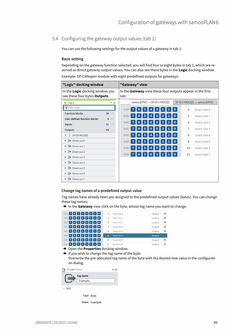
Configuration of gateways with samosPLAN 6
| BA000970 | 03/2020 [10244] 49
Configuring the gateway output values (tab 1) 80889739
You can use the following settings for the output values of a gateway in tab 1:
Basic setting Depending on the gateway function selected, you will find four or eight bytes in tab 1, which are re-served as direct gateway output values. You can also see these bytes in the Logic docking window.
Example: SP-CANopen module with eight predefined outputs for gateways:
"Logic” docking window "Gateway" view
In the Logic docking window you see these four bytes Outputs:
In the Gateway view these four outputs appear in the first tab:
Change tag names of a predefined output value Tag names have already been pre-assigned to the predefined output values (bytes). You can change these tag names: In the Gateway view click on the byte, whose tag name you want to change.
Open the Properties docking window. If you wish to change the tag name of the byte:
Overwrite the pre-allocated tag name of the byte with the desired new value in the configurati-on dialog.
5.4

Configuration of gateways with samosPLAN 6
| BA000970 | 03/2020 [10244] 50
If you also want to change the tag names of individual bits: Overwrite the pre-allocated values with the desired new value under Parameters in the confi-guration dialog.
In the Logic view, these bits will appear with the corresponding tag names.
Configuring additional direct gateway output values You can add new output values (bytes) in addition to the pre-allocated output values in the Gate-way view. Click on an empty byte in the Gateway view.
Open the Properties docking window and assign a tag name for the byte in the configuration
dialog.
Tag names for all bits are automatically pre-allocated under Parameters.
If you also want to change the tag names of individual bits:
Overwrite the pre-allocated values with the desired new value under Parameters in the confi-guration dialog.
In the Logic view, these bits will appear with the corresponding tag names.

Configuration of gateways with samosPLAN 6
| BA000970 | 03/2020 [10244] 51
Editing the gateway input values (tab 2) 80913931
You can use the following settings for the output values of a gateway in tab 2:
Basic setting Depending on the gateway function selected, you will find four or eight bytes in tab 2, which are re-served as direct gateway input values. You can also see these bytes in the Logic docking window.
Example: SP-CANopen module with four predefined inputs for gateways:
"Logic” docking window "Gateway" view
In the Logic docking window you see these four bytes under Inputs:
In the Gateway view, these four inputs appear in tab 2:
Change tag names of a predefined input value Tag names have already been pre-assigned to the predefined input values (bytes). You can change these tag names: In the Gateway view click on the byte, whose tag name you want to change.
Open the Properties docking window. If you wish to change the tag name of the byte:
Overwrite the pre-allocated tag name of the byte with the desired new value in the configurati-on dialog.
5.5
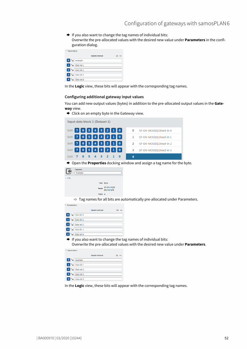
Configuration of gateways with samosPLAN 6
| BA000970 | 03/2020 [10244] 52
If you also want to change the tag names of individual bits: Overwrite the pre-allocated values with the desired new value under Parameters in the confi-guration dialog.
In the Logic view, these bits will appear with the corresponding tag names.
Configuring additional gateway input values You can add new output values (bytes) in addition to the pre-allocated output values in the Gate-way view. Click on an empty byte in the Gateway view.
Open the Properties docking window and assign a tag name for the byte.
Tag names for all bits are automatically pre-allocated under Parameters.
If you also want to change the tag names of individual bits:
Overwrite the pre-allocated values with the desired new value under Parameters.
In the Logic view, these bits will appear with the corresponding tag names.

Configuration of gateways with samosPLAN 6
| BA000970 | 03/2020 [10244] 53
Monitoring process data 80943627
You can monitor your gateway configuration directly in samosPLAN 6. This can be done in simulati-on mode (limited monitoring option) or by means of an active link to a samosPRO system.
NOTICE The samosPRO gateways always show the actual physical state of the inputs and outputs of the connected modules and equipment. This means that even when the force mode is active and in-puts that are physically Low are forced to High (or vice versa), the actual physical state of these inputs is transmitted to the PLC and not the (virtual) forced state. However, if one or several out-puts change their state as a result of one or several inputs being forced, the changed state of these outputs will also be transmitted to the PLC, as the actual physical state of the equipment outputs has changed.
Simulation mode (offline mode) You can test a gateway configuration offline in simulation mode. Use the logic analyzer for this pur-pose and manually set the desired inputs to High or Low.
Read here how to work with the simulation mode and logic analyzer: Software manual, chapter "Simulating logic programming"
Monitoring with an active connection (online mode) You can also test a gateway configuration online by establishing a link between samosPLAN 6 and a samosPRO system.
Read here how to activate the online mode and what you need to take into account: Software ma-nual, chapter "Connecting to the safety controller"
NOTICE LED behavior for active connections If you are linked to a samosPRO installation, the status LEDs in the Modules view of samosPLAN 6 will light up in the same way as for the connected system. Further information about the status LEDs may be found in the documentation for the relevant module:
• Modbus TCP gateway [ch. 6.4, p. 63] • PROFIBUS-DB gateway [ch. 9.4, p. 131] • CANopen gateway [ch. 10.14, p. 169]
5.6

Modbus TCP gateway
| BA000970 | 03/2020 [10244] 54
MODBUS TCP GATEWAY
77973771
The controller module SP-COP2-ENI can be used for Modbus TCP. The internal SP-EN-MOD (Modbus TCP Gateway) is a component of the SP-COP2-ENI device and is activated by the gateway configura-tion:
Illustration 8: Activation of Modbus TCP on the SP-COP2-ENI module
The Modbus TCP gateway supports the following: • Modbus TCP with master and slave operation • Ethernet TCP/IP socket interface, polling and auto-update function
Interfaces and operation 77992459
The SP-COP2-ENI is equipped with a RJ-45 socket.
Illustration 9: Interfaces and display elements
Further information • Here in this manual:
Diagnostics and troubleshooting [ch. 6.4, p. 63] • In the hardware manual:
Device state and LED displays in the controller modules
6
6.1

Modbus TCP gateway
| BA000970 | 03/2020 [10244] 55
Basic configuration – allocation of an IP address 78009227
The SP-COP2-ENI module is configured with the help of the samosPLAN 6 configuration software. Step 1: Add SP-COP2-ENI module Start samosPLAN 6 and open the Modules docking window. Add the controller module SP-COP2-ENI.
Instructions: Software manual, chapter "Adding modules"
Step 2: Open configuration dialog Switch to the Project structure docking window. Click on the top element, which represents the controller.
Open the Properties docking window.
You will see the controller configuration dialog.
Step 3: Store configuration Enter the following values under Control configuration:
- valid IP address - subnet mask - if required: valid IP address for a default gateway OR: Alternatively activate DHCP.
Ensure that samosPLAN 6 is connected to the samosPRO system. The samosPRO system must not be in Run (Execute) mode. The Start/Stop button in the command bar of the Modules view must be set to Start.
More detailed information on the link to the controls: Software manual, chapter "Connecting to the safety controller"
Click Send in the Properties docking window to transfer the configuration to the samosPRO system.
6.2
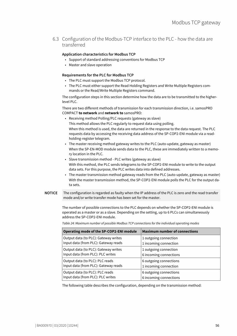
Modbus TCP gateway
| BA000970 | 03/2020 [10244] 56
Configuration of the Modbus-TCP interface to the PLC - how the data are transferred 78055051
Application characteristics for Modbus TCP • Support of standard addressing conventions for Modbus TCP • Master and slave operation
Requirements for the PLC for Modbus TCP • The PLC must support the Modbus TCP protocol. • The PLC must either support the Read Holding Registers and Write Multiple Registers com-
mands or the Read/Write Multiple Registers command.
The configuration steps in this section determine how the data are to be transmitted to the higher-level PLC.
There are two different methods of transmission for each transmission direction, i.e. samosPRO COMPACT to network and network to samosPRO: • Receiving method Polling/PLC requests (gateway as slave)
This method allows the PLC regularly to request data using polling. When this method is used, the data are returned in the response to the data request. The PLC requests data by accessing the receiving data address of the SP-COP2-ENI module via a read-holding-register telegram.
• The master receiving method gateway writes to the PLC (auto-update, gateway as master) When the SP-EN-MOD module sends data to the PLC, these are immediately written to a memo-ry location in the PLC.
• Slave transmission method - PLC writes (gateway as slave) With this method, the PLC sends telegrams to the SP-COP2-ENI module to write to the output data sets. For this purpose, the PLC writes data into defined addresses.
• The master transmission method gateway reads from the PLC (auto-update, gateway as master) With the master transmission method, the SP-COP2-ENI module polls the PLC for the output da-ta sets.
NOTICE The configuration is regarded as faulty when the IP address of the PLC is zero and the read transfer mode and/or write transfer mode has been set for the master.
The number of possible connections to the PLC depends on whether the SP-COP2-ENI module is operated as a master or as a slave. Depending on the setting, up to 6 PLCs can simultaneously address the SP-COP2-ENI module.
Table 24: Maximum number of possible Modbus TCP connections for the individual operating modes
Operating mode of the SP-COP2-ENI module Maximum number of connections
Output data (to PLC): Gateway writes Input data (from PLC): Gateway reads
1 outgoing connection 1 incoming connection
Output data (to PLC): Gateway writes Input data (from PLC): PLC writes
1 outgoing connection 6 incoming connections
Output data (to PLC): PLC reads Input data (from PLC): Gateway reads
6 outgoing connections 1 incoming connection
Output data (to PLC): PLC reads Input data (from PLC): PLC writes
6 outgoing connections 6 incoming connections
The following table describes the configuration, depending on the transmission method:
6.3

Modbus TCP gateway
| BA000970 | 03/2020 [10244] 57
Gateway is master Table 25: Configuration directive – gateway as master
Essential settings in the gateway configurati-on (via SP-COP2-ENI)
Settings required for the PLC program and/or in the Modbus TCP configuration tool
Choose Gateway writes to tag/file and/or Ga-teway reads from register to configure the gateway as a master.
–
Select which data are to be written to the PLC or read from it.
–
Define where the selected data in the PLC me-mory are to be written to: Enter the register address(es). Example: "40001" and/or you can determine from which location in the PLC memory the selected data are to be read: Enter the register addresses.
Ensure that the addresses allocated in the sa-mosPRO are available and that they contain the data intended for the samosPRO- system.
Choose how often these data are to be transmit-ted.
–
Define from and to where the data in the Modbus-TCP network are to be read and written: Enter the IP address and the slot number of the PLC controller.
–
Gateway as slave Table 26: Configuration directive – gateway as slave
Essential settings in the gateway configurati-on (via SP-COP2-ENI)
Settings required for the PLC program and/or in the Modbus TCP configuration tool
Select PLC requests and PLC writes in the ga-teway configuration dialog.
–
– Select which data are to be written to the gate-way or read from it. Ensure that the PLC program writes the data into the addresses allocated to the gateway (see Table "Data addressing for the SP-COP2-ENI as recipient [ch. 6.3, p. 62]").
NOTICE The address settings for the Modbus TCP gateway are 1-based. Please subtract 1 from the register address set in samosPLAN 6 for a 0-based address setting. Example: Register 1100 corresponds to the Modbus address 1099.

Modbus TCP gateway
| BA000970 | 03/2020 [10244] 58
Master mode: SP-COP2-ENI reads from/writes to the PLC Carry out the following steps to configure the gateway as a master: Change to the Gateway view and click on the Gateway configuration tab. Select the samosPRO is Master/Client option at the very bottom of the Modbus mode section.
The settings required for master mode are activated automatically in the Output data (to PLC)
and Input data (from PLC) sections.
Quick reference
You can make the following additional settings:
“Output data (to PLC)” section
Area highlighted in gray
Selection list Set automatically: Determines the transmission method. Value required for master mode: samosPRO writes (Master)
All data sets in one tag Optional Defines that all data sets are to be written to a single address in the PLC memory. In this case the register address defined for Data Set 1 will be used.
Note: The following two settings can be activated simultaneously. They determine the frequency of data transmission.
Activating updates following changes
Recommended Determines that the SP-COP2-ENI module immediately up-dates the data in the PLC as soon as changes are made to the data sets.
Activate heartbeat interval Recommended Use the heartbeat intervals which you defined in the Heart-beat interval column to activate the update of the selected data sets.

Modbus TCP gateway
| BA000970 | 03/2020 [10244] 59
“Output data (to PLC)” section
Columns highlighted white
Data set Determines which data are to be written to the PLC or read from it. Select the checkboxes for the desired data sets. You will find a detailed description of the data sets here: Data transferred to the network (network input data sets) [ch. 3.2, p. 20]
Register Define from and to where in the PLC memory the selected data should be read and written.
Heartbeat interval (ms) Defines how often the data sets are to be updated. Requirement: You have selected the option Activate heart-beat interval (see above).
Register range Shows the registers in the PLC to which the process data is written.
“Input data (from PLC)” section
Selection list 1 Set automatically: Determines the transmission method. Value required for master mode: samosPRO reads (Master)
Selection list 2 Defines which of the two modbus commands is used: • Read holding registers:
Activates the Read holding registers command (see "Module commands" table below).
• Read input registers: Activates the Read input registers command (see "Mo-dule commands" table below).
Data set column Determines which data are to be written to the PLC or read from it. Mark the control boxes for the desired data sets for this pur-pose. You will find a detailed description of the data sets here: Data transferred to the network (network input data sets) [ch. 3.2, p. 20]
Register column Define from and to where in the PLC memory the selected data should be read and written.
Column heartbeat interval Defines how often the data sets are to be updated.
"Modbus mode” section
PLC IP address Device ID
The parameters define from and to where the data in the Modbus-TCP network are to be read and written:
Maximum refresh time for PLC Define the maximum rate (or the minimum time interval) for transmitting the data sets to the PLC. This setting depends on the processing speed of the PLC. Minimum = 10 ms, ma-ximum = 65535 ms. The basic setting of 40 ms is suitable for most PLC Note: When these values are greater than the heartbeat in-terval, the heartbeat interval will be slowed down to this value.
Combine samosPLAN 6 with the samosPRO system and transmit the configuration. More detailed information on the link to the controls: Software manual, chapter "Connecting to the safety controller"

Modbus TCP gateway
| BA000970 | 03/2020 [10244] 60
Write to the PLC
NOTICE The following restrictions apply when the gateway operates as a master and writes the input data sets to the PLC:
• The address of the input data sets (preset in samosPLAN 6) must be the same as defined in the PLC.
• The PLC variable that is to incorporate the data must meet the following conditions: – in the address range 40xxxx (for Schneider Modicon PLC), – an array of 16-bit words, – long enough to contain the defined input data set array.
• All input data sets are transmitted to the PLC in 16-bit word format, with the first byte having the lowest value, i.e. on the far right of the integer, while the second byte has the highest value, i.e. on the very left of the integer.
Reading from the PLC
NOTICE The following restrictions apply when the gateway operates as a master and reads the output data sets from the PLC:
• The address of the output data sets must be the same as defined in the PLC. Please note: The value of the Modbus addresses must be 1 lower than the register data. See al-so: "Figure 8" in "MODBUS Application Protocol V1.1b3"
• The PLC variable from which the data are requested must meet the following conditions: – They fall into the address range 40xxxx (for Schneider Modicon PLCs). – There is an array of 16-bit words for the output data sets that is long enough to accommo-
date the entire output data set. • All output data sets are transmitted to the PLC in 16-bit word format, with the first byte having
to be placed as the lowest value, i.e. on the far right of the integer, while the second byte will have the highest value, i.e. on the very left of the integer.
Slave/server mode - PLC reads from / writes to SP-COP2-ENI In this operating mode, the SP-COP2-ENI module provides the data as a slave at the request of the PLC. If this operating mode is desired: Launch samosPLAN 6. Change to the Gateway view and click on the Gateway configuration tab. Select the samosPRO is Slave/Server option at the very bottom of the Modbus mode section.
The minimum settings required for slave mode are activated automatically in the Output data
(to PLC) and Input data (from PLC) sections. Unavailable options are grayed out.
You can make the following additional settings:

Modbus TCP gateway
| BA000970 | 03/2020 [10244] 61
Table 27: "Output data (to PLC)" and "Input data (from PLC)” sections
Setting Description/procedure
Data set column Determines which data can be written to the PLC or read from it. Mark the control boxes for the desired data sets for this pur-pose. You will find a detailed description of the data sets here: Data transferred to the network (network input data sets) [ch. 3.2, p. 20]
Size (bytes) column Exact number of bytes to be read out or written. The number of 16-bit data types usual for TCP modbus is exactly half.
Register range column Registers to be addressed in SP-COP2-ENI
Combine samosPLAN 6 with the samosPRO system and transmit the configuration. More detailed information on the link to the controls: Software manual, chapter "Connecting to the safety controller"
PLC writes output data sets The following restrictions apply when the PLC writes the output data sets: • The equipment index must not be equal to zero. • The telegram must be sent in Word format. • All output data sets are transmitted to the PLC in 16-bit word format, with the first byte having
to be placed as the lowest value, i.e. on the far right of the integer, while the second byte will have the highest value, i.e. on the very left of the integer.
PLC polls the input data sets • The following restrictions apply: • The equipment index must not be equal to zero. • The PLC variable that is to incorporate the data must meet the following conditions:
– It falls into the address range 40xxxx (for Schneider Modicon PLCs). – There is an array of 16-bit words that is long enough to accommodate the entire output da-
ta set. • All input data sets are transmitted to the PLC in 16-bit word format, with the first byte having
the lowest value, i.e. on the far right of the integer, while the second byte has the highest value, i.e. on the very left of the integer.
NOTICE Configure the PLC data polling in such a way that a data telegram is exchanged at least every mi-nute between SP-COP2-ENI and the PLC. The TCP connection will otherwise be interpreted as not used and terminated.
NOTICE The data from the PLC to the SP-COP2-ENI module assumes the value zero in the samosPLAN 6 logic program if the Modbus TCP connection is terminated by the PLC itself or by a timeout.
SP-COP2-ENI as slave – data addressing The following table lists the addresses for reading out the data sets.

Modbus TCP gateway
| BA000970 | 03/2020 [10244] 62
Unit ID 1 Table 28: Data addressing for the SP-COP2-ENI as recipient
Register (Base 1)
Description Access Scope (words)
1000 Request data for all activated input data sets Reading 1..101 1)
1100 Request data from input data block 1-5 Reading 1..25
1200 Request CRC data Reading 1..16
1300 Request diagnostic data Reading 1..30
1400 Reserved Reading 1..30
2000 Write all activated output data sets Read, write 1..25 2)
2100 Write data from output data set 1 Read, write 1..5
2200 Write data from output data set 2 Read, write 1..5
2300 Write data from output data set 3 Read, write 1..5
2400 Write data from output data set 4 Read, write 1..5
2500 Write data from output data set 5 Read, write 1..5 1) Corresponds to all activated input data sets. 2) Must correspond to all activated output data sets. Example: If only output data sets 1 and 2 have been activated, 10 words (20 bytes) must be written. If all output data sets have been activated, 25 words (50 bytes) must be written.
Modbus commands and error messages The SP-COP2-ENI module supports the following Modbus commands and error messages:
Table 29: Modbus commands
Modbus command Value
Read holding registers 3
Read input1) registers 4
Write single register 6
Write multiple registers 16 (10hex)
Read/write multiple registers 23 (17hex) 1) starting with module version A-03
Table 30: Modbus error messages
Modbus error response Description
1 Function not permitted The requested function is not supported
2 Data address not permitted Undefined data address received
3 Data value not permitted Request with prohibited data values, e.g. insuffi-cient data requested for a data set
4 server errors An error occurred during execution of the server.

Modbus TCP gateway
| BA000970 | 03/2020 [10244] 63
Diagnosis and troubleshooting 78190219
You can find information on diagnosis of the samosPRO system in the software manual.
Table 31: Troubleshooting on the SP-COP2-ENI
Error Possible cause Possible remedy
Key: LED off / LED flashes / LED lights up
samosPLAN 6 cannot set up a connection to the samosPRO gateway.
• The SP-COP2-ENI module has no power supply.
• The SP-COP2-ENI module is not in the same physical network as the PC.
• A different subnet mask has been set in the TCP/IP settings for the PC.
• The module was been preconfigured and has a permanently set IP address or an IP address allocated to a DHCP server that has not been allocated.
• Switch on the power supp-ly. Check the Ethernet wiring and the network set-tings of the P and correct them where necessary.
• Set the PC to a network address 192.168.1.0 (The delivery state of the SP-COP2-ENI module has the address 192.168.1.4, which may not be used for the PC).
• Alternatively activate DHCP on the PC and link the SP-COP2-ENI module and the PC to a network, using an active DHCP server.
• Check the communication settings in samosPLAN 6.
The SP-COP2-ENI module does not provide any data.
• The SP-COP2-ENI module has been configured for da-ta transmission to the PLC, but no Ethernet communi-cation has been establis-hed or the communication is faulty.
• Duplicate IP address detec-ted. Another network de-vice has the same IP address.
At least one Ethernet link must be established. • Set up the Ethernet link on
the PC, check the Ethernet wiring, check the Ethernet settings in the PLC and in samosPLAN 6.
• If no Ethernet communica-tion is required, deactivate the Ethernet connections / PLC interfaces on the SP-COP2-ENI.
• Correct the IP address and switch the system off and on again.
LED PWR/EC Green
LED LINK Green
LED ACT Orange
The SP-COP2-ENI module does not provide any data.
• Configuration required. • The configuration has not
yet been fully transmitted. • The module version of the
controller module does not support the gateway func-tion.
• Configure the SP-COP2-ENI module and transfer the configuration to the sys-tem.
• Wait until the configuration has been fully transferred.
• Use the controller module with the required module version.
LED PWR/EC Green
LED LINK Green
LED ACT Orange
MS LED Red (1 Hz)
The SP-COP2-ENI module does not provide any data.
• No data set was activated. • No Ethernet communicati-
• Activate at least one data set.
6.4
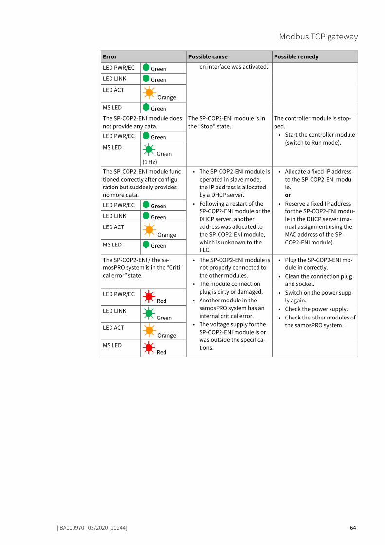
Modbus TCP gateway
| BA000970 | 03/2020 [10244] 64
Error Possible cause Possible remedy
LED PWR/EC Green on interface was activated.
LED LINK Green
LED ACT Orange
MS LED Green
The SP-COP2-ENI module does not provide any data.
The SP-COP2-ENI module is in the “Stop” state.
The controller module is stop-ped. • Start the controller module
(switch to Run mode). LED PWR/EC Green
MS LED Green
(1 Hz)
The SP-COP2-ENI module func-tioned correctly after configu-ration but suddenly provides no more data.
• The SP-COP2-ENI module is operated in slave mode, the IP address is allocated by a DHCP server.
• Following a restart of the SP-COP2-ENI module or the DHCP server, another address was allocated to the SP-COP2-ENI module, which is unknown to the PLC.
• Allocate a fixed IP address to the SP-COP2-ENI modu-le. or
• Reserve a fixed IP address for the SP-COP2-ENI modu-le in the DHCP server (ma-nual assignment using the MAC address of the SP-COP2-ENI module).
LED PWR/EC Green
LED LINK Green
LED ACT Orange
MS LED Green
The SP-COP2-ENI / the sa-mosPRO system is in the “Criti-cal error” state.
• The SP-COP2-ENI module is not properly connected to the other modules.
• The module connection plug is dirty or damaged.
• Another module in the samosPRO system has an internal critical error.
• The voltage supply for the SP-COP2-ENI module is or was outside the specifica-tions.
• Plug the SP-COP2-ENI mo-dule in correctly.
• Clean the connection plug and socket.
• Switch on the power supp-ly again.
• Check the power supply. • Check the other modules of
the samosPRO system.
LED PWR/EC Red
LED LINK Green
LED ACT Orange
MS LED Red

Modbus TCP gateway
| BA000970 | 03/2020 [10244] 65
State bits 78215947
The Modbus TCP Gateway SP-EN-MOD sets status bits, which are available in the logic editor of sa-mosPLAN 6 for processing.
Table 32: Meaning of the state bits SP-EN-MOD[0] in the logic editor
Name of the state bits Set to 1, if ... Reset to 0 ...
Output status ... At least one output data byte was sent without error.
... If there is a missing Modbus TCP connection to the PLC.
Input status ... At least one input data byte was sent without error.
... If there is a missing Modbus TCP connection to the PLC.
Internal state … The Modbus function in SP-COP2-ENI is ready for communi-cation From module version E-01.01: If the Modbus function in SP-COP2-ENI is ready for communi-cation or if at least one input or output byte was downloaded or transmitted without errors.
... If an error has occurred in the Modbus function.
6.5

PROFINET IO-Gateway
| BA000970 | 03/2020 [10244] 66
PROFINET IO-GATEWAY
79046283
The SP-COP2-ENI module can be used for PROFINET IO.
You will find the GSDM file and the equipment symbol for integration in a PLC of the product website of the SP-COP2-ENI module on the Internet (http://www.wielandinc.com/).
The internal SP-EN-PN (PROFINET IO Gateway) module is part of the device SP-COP2-ENI. You can activate it in the configuration dialog of the SP-COP2-ENI module in the Properties docking window:
NOTICE Selection of SP-EN-PN is possible on the SP-COP2-ENI module starting from module version B-xx.
Supported features The SP-COP2-ENI module supports:
• PROFINET IO Conformance Class A • Cyclical EA communication (RT) • LLDP • DCP
• Auto MDI • Auto negotiation • I&M 1-4 • Equipment diagnostics, alarms
Currently not supported:
• SNMP • Shared Input, Shared Device • FSU
• MIB II • Port statistics
The number of PROFINET controllers (PLCs) which can simultaneous connect to a SP-COP2-ENI de-vice via PROFINET is limited to one.
Interfaces and operation 79071115
Interfaces and operation are identical to that of the Modbus TCP Gateway.
Read the following section: Interfaces and operation [ch. 6.1, p. 54]
7
7.1

PROFINET IO-Gateway
| BA000970 | 03/2020 [10244] 67
Basic configuration - Assigning a device name and an IP address 79080203
Configuration and diagnostics of the SP-COP2-ENI is possible both with the help of the samosPLAN 6 configuration software and the PROFINET IO network programming tool (e.g. SIEMENS TIA Portal).
Configuration using PROFINET IO In the delivery state, a MAC address is stored in every PROFINET IO field device such as the SP-COP2-ENI module. The symbolic name (NameOfStation) Test station is stored on the SD card in the de-livery state.
NOTICE • In accordance with IEC 61158-6-10 no capital letters are permitted for the symbolic name (NameOfStation).
• This NameOfStation is used by the I/O controller (e.g. the PLC) to assign an IP address to the field device.
• If the IP address is also used for other communication via Ethernet, such as TCP/IP or for the configuration via Ethernet, please note that the PLC changes the IP address and can thus inter-rupt the other communication.
The IP address is assigned in two steps. Assign a unique system-specific name to the Gateway, using either the network configuration
tool such as SIEMENS TIA Portal, or using the samosPLAN 6 software. In samosPLAN 6 this is the Connection name. Where do you edit the connection name in samosPLAN 6? Open the Project structure docking window and there click on the Controller entry right at the top. Additionally open the Proper-ties docking window and enter the desired value there in the configuration dialog under Connection name.
A (unique) system-specific name can be used by the I/O-Controller (i.e. the PLC) to assign the IP address to the gateway now before the system is booted.
NOTICE The MAC address of the SP-COP2-ENI module is printed on the device's nameplate (Example: 00:07:17:02:03:05).
Using the Siemens TIA Portal to assign device names In the Online accesses area, select the network card connected to the network which can be used to access the SP-COP2-ENI device. In the Assign name function area, edit the PROFINET device name field and then select Assign name.
This will permanently assign the new device name to the SP-COP2-ENI device.
Illustration 10: Assigning device names with the TIA portal
7.2
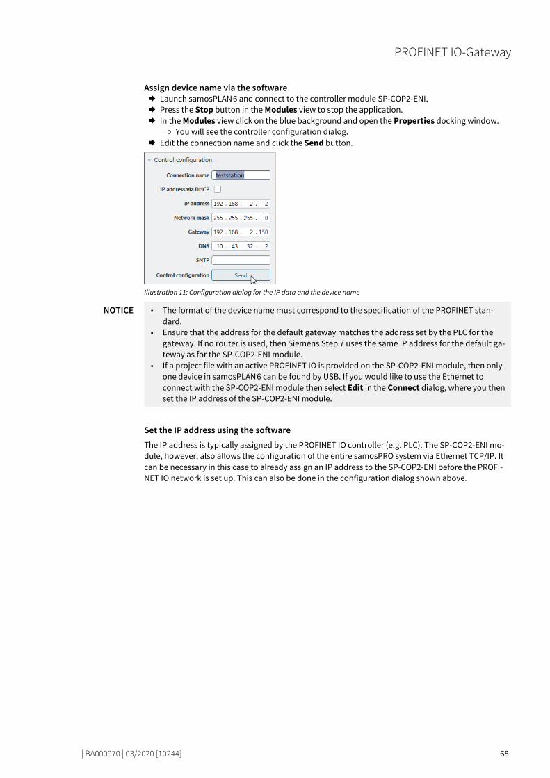
PROFINET IO-Gateway
| BA000970 | 03/2020 [10244] 68
Assign device name via the software Launch samosPLAN 6 and connect to the controller module SP-COP2-ENI. Press the Stop button in the Modules view to stop the application. In the Modules view click on the blue background and open the Properties docking window.
You will see the controller configuration dialog. Edit the connection name and click the Send button.
Illustration 11: Configuration dialog for the IP data and the device name
NOTICE • The format of the device name must correspond to the specification of the PROFINET stan-dard.
• Ensure that the address for the default gateway matches the address set by the PLC for the gateway. If no router is used, then Siemens Step 7 uses the same IP address for the default ga-teway as for the SP-COP2-ENI module.
• If a project file with an active PROFINET IO is provided on the SP-COP2-ENI module, then only one device in samosPLAN 6 can be found by USB. If you would like to use the Ethernet to connect with the SP-COP2-ENI module then select Edit in the Connect dialog, where you then set the IP address of the SP-COP2-ENI module.
Set the IP address using the software The IP address is typically assigned by the PROFINET IO controller (e.g. PLC). The SP-COP2-ENI mo-dule, however, also allows the configuration of the entire samosPRO system via Ethernet TCP/IP. It can be necessary in this case to already assign an IP address to the SP-COP2-ENI before the PROFI-NET IO network is set up. This can also be done in the configuration dialog shown above.

PROFINET IO-Gateway
| BA000970 | 03/2020 [10244] 69
PROFINET configuration of the gateway - how the data are transferred 79157003
The following steps are required to configure the communication between the PLC and the gateway.
NOTICE This documentation does not address the installation of the PROFINET IO network or the other components of the automation system project in the network configuration tool. It is assumed that the PROFINET project in the configuration program, e.g. the SIEMENS TIA Portal, has already been set up. The examples presented are based on configurations created with the help of the SIEMENS TIA Portal.
Step 1: Install the device master file (GDSML file) Before the SP-COP2-ENI module can be used for the first time as part of the network configuration tool, e.g. the SIEMENS TIA Portal, the device master file (GSDML file) of the gateway must first be in-stalled in the hardware catalog of the tool. Download the GSDML file and the equipment symbol from the product site of the SP-COP2-ENI
module (https://eshop.wieland-electric.com/). Follow the instructions for the installation of GSD files in the online help section or in the user
manual for the PROFINET network configuration tool.
If you are using SIEMENS TIA Portal, then the SP-COP2-ENI module appears in the following location in the hardware catalog:
Additional field devices > PROFINET IO > I/O > Wieland Electric > samosPRO COMPACT > Head module > SP-COP2-ENI
7.3
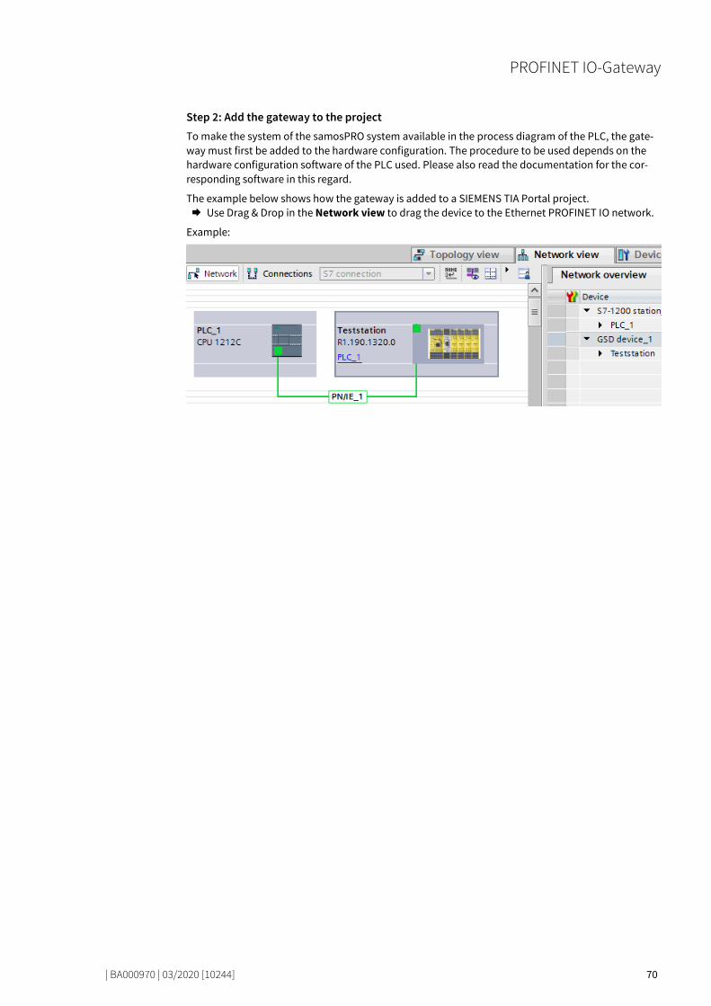
PROFINET IO-Gateway
| BA000970 | 03/2020 [10244] 70
Step 2: Add the gateway to the project To make the system of the samosPRO system available in the process diagram of the PLC, the gate-way must first be added to the hardware configuration. The procedure to be used depends on the hardware configuration software of the PLC used. Please also read the documentation for the cor-responding software in this regard.
The example below shows how the gateway is added to a SIEMENS TIA Portal project. Use Drag & Drop in the Network view to drag the device to the Ethernet PROFINET IO network.
Example:
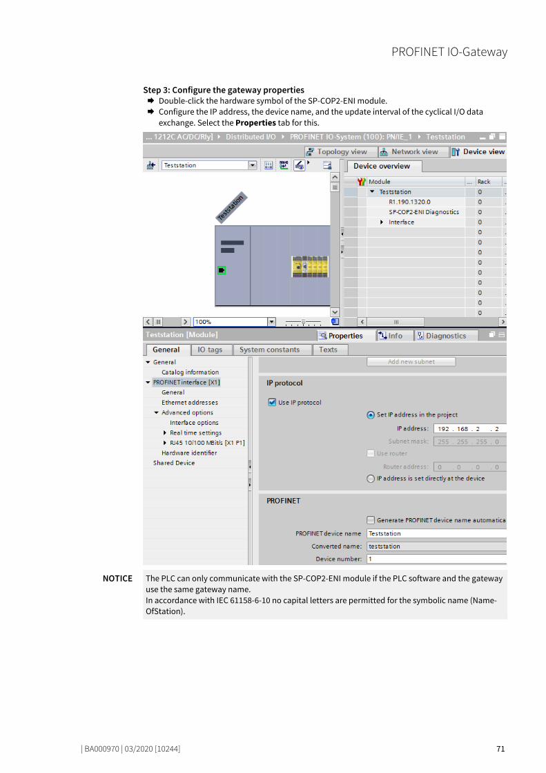
PROFINET IO-Gateway
| BA000970 | 03/2020 [10244] 71
Step 3: Configure the gateway properties Double-click the hardware symbol of the SP-COP2-ENI module. Configure the IP address, the device name, and the update interval of the cyclical I/O data
exchange. Select the Properties tab for this.
NOTICE The PLC can only communicate with the SP-COP2-ENI module if the PLC software and the gateway use the same gateway name. In accordance with IEC 61158-6-10 no capital letters are permitted for the symbolic name (Name-OfStation).

PROFINET IO-Gateway
| BA000970 | 03/2020 [10244] 72
PROFINET configuration of the gateway - which data are transferred 79202571
Cyclical data The physical I/O modules are not presented in the PROFINET IO hardware catalog as typical hard-ware modules in the network. Instead, the data provided by the samosPRO system has been arran-ged in various data blocks. Every data block represents a module in the PROFINET IO hardware ca-talog. The GSDML supports 13 Slots in which the modules can be placed. This makes is possible to use each data set one time (see illustration "Configuration" [ch. 7.4, p. 74]).
Process data from module to PLC The SP-COP2-ENI module provides 5 input data blocks (virtual device modules) which contain the process image. These can be exclusively placed in each corresponding slot 16 to 20.
NOTICE Input data blocks 1 to 4 each contain 12 bytes, while input data block 5 contains 2 bytes.
The content of the input data blocks can be freely selected. The data assignment in samosPLAN 6 is pre-configured in accordance with the following:
Table 33: Predefined content of input data block 1 to 5 of the SP-COP2-ENI module
Data block 1 Data block 2 Data block 3 Data block 4 Data block 5
Byte no. per data block
Input data Input data Input data Input data Input data
Byte 0 Input values SP-COP2-ENI
I/O module 1 input values
I/O module 1 output values
Not allocated Not allocated
Byte 1 Input values SP-COP2-ENI
I/O module 2 input values
I/O module 2 output values
Not allocated Not allocated
Byte 2 Input values SP-COP2-ENI
I/O module 3 input values
I/O module 3 output values
Not allocated Not available
Byte 3 Output values SP-COP2-ENI
I/O module 4 input values
I/O module 4 output values
Not allocated
Byte 4 Logic data values I/O module 5 input values
I/O module 5 output values
Not allocated
Byte 5 Logic data values I/O module 6 input values
I/O module 6 output values
Not allocated
Byte 6 Logic data values I/O module 7 input values
I/O module 7 output values
Not allocated
Byte 7 Logic data values I/O module 8 input values
I/O module 8 output values
Not allocated
Byte 8 Logic data values I/O module 9 input values
I/O module 9 output values
Not allocated
Byte 9 Logic data values I/O module 10 input values
I/O module 10 output values
Not allocated
Byte 10 Logic data values I/O module 11 input values
I/O module 11 output values
Not allocated
Byte 11 Logic data values I/O module 12 input values
I/O module 12 output values
Not allocated
Length 12 bytes 12 bytes 12 bytes 12 bytes 2 bytes
Byte offset 0 12 24 36 48
1 byte for data set 1 is available for every expansion module. The input values show the state of the preliminary evaluation of the I/O module. This corresponds to the state of the element in the con-troller module logic. The level at the associated terminal cannot be clearly detected from this, as the
7.4

PROFINET IO-Gateway
| BA000970 | 03/2020 [10244] 73
data may be set to low, irrespectively of the level at the input terminal, by means of the cross-connection detection or two-channel evaluation (e.g. I1-18).
When two-channel input elements have been configured for an I/O module, only the lower-value bit represents the pre-evaluation state of the corresponding element (e.g. bit 0 for I1 and I2, bit 2 for I3 and I4, bit 4 for I5 and I6, bit 6 for I7 and I8). The higher-value bit (bit 1, 3, 5 and 7) is used as follows in this case: 0 = error, 1 = no error
Further information
You will find information about how to configure the process diagram in the description of the (The graphical user interface [ch. 5.1, p. 40]) user interface.
Data from the PLC to the SP-COP2-ENI module There are 5 output data blocks having 10 bytes each. These can be exclusively placed in each cor-responding slot 21 to 25.
The content of these data blocks can be used as input in the samosPLAN 6 logic editor or forwarded to another network by a second gateway. Every bit to be used must be assigned a tag name in order to provide the desired bits in the logic editor or for forwarding. Bits without tag names are not available.
Detailed information about how you can assign and adapt the tag names of the input and output da-ta can be found here: Software manual, chapter "Adapting display names of project components"
NOTICE The standard value of the gateway data bit is zero following activation of the SP-COP2-ENI device. If the connection to PLC is terminated, then all of the gateway data bits in the samosPLAN 6 logic editor assume the value zero.
NOTICE For output data with IOPS=Bad, all of the gateway data bits in the samosPLAN 6 logic editor assu-me the value zero. This is the case, for example, if the PLC is stopped.
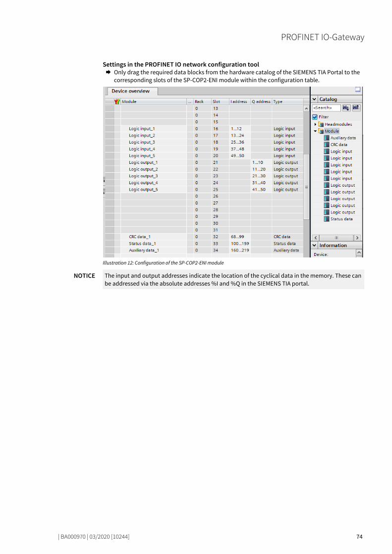
PROFINET IO-Gateway
| BA000970 | 03/2020 [10244] 74
Settings in the PROFINET IO network configuration tool Only drag the required data blocks from the hardware catalog of the SIEMENS TIA Portal to the
corresponding slots of the SP-COP2-ENI module within the configuration table.
Illustration 12: Configuration of the SP-COP2-ENI module
NOTICE The input and output addresses indicate the location of the cyclical data in the memory. These can be addressed via the absolute addresses %I and %Q in the SIEMENS TIA portal.
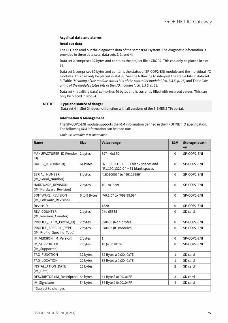
PROFINET IO-Gateway
| BA000970 | 03/2020 [10244] 75
Acyclical data and alarms Read out data
The PLC can read out the diagnostic data of the samosPRO system. The diagnostic information is provided in three data sets, data sets 2, 3, and 4:
Data set 2 comprises 32 bytes and contains the project file's CRC 32. This can only be placed in slot 32.
Data set 3 comprises 60 bytes and contains the status of SP-COP2-ENI module and the individual I/O modules. This can only be placed in slot 33. See the following to interpret the status bits in data set 3: Table "Meaning of the module status bits of the controller module" [ch. 3.3.5, p. 27] and Table "Me-aning of the module status bits of the I/O modules" [ch. 3.3.5, p. 28]
Data set 4 (auxiliary data) comprises 60 bytes and is currently filled with reserved values. This can only be placed in slot 34.
NOTICE Type and source of danger Data set 4 in Slot 34 does not function with all versions of the SIEMENS TIA portal.
Information & Management
The SP-COP2-ENI module supports the I&M information defined in the PROFINET IO specification. The following I&M information can be read out:
Table 34: Readable I&M information
Name Size Value range I&M Storage locati-on
MANUFACTURER_ID (Vendor ID)
2 bytes 397 = 0x18D 0 SP-COP2-ENI
ORDER_ID (Order ID) 64 bytes "R1.190.1310.0 + 51 blank spaces and "R1.190.1320.0 " + 51 blank spaces
0 SP-COP2-ENI
SERIAL_NUMBER (IM_Serial_Number)
8 bytes "16010001" to "99129999" 0 SP-COP2-ENI
HARDWARE_REVISION (IM_Hardware_Revision)
2 bytes 101 to 9999 0 SP-COP2-ENI
SOFTWARE_REVISION (IM_Software_Revision)
6 to 9 Bytes "V0.1.0" to "V99.99.99" 0 SP-COP2-ENI
Device ID 1320 0 SP-COP2-ENI
REV_COUNTER (IM_Revision_Counter)
2 bytes 0 to 65535 0 SD card
PROFILE_ID (IM_Profile_ID) 2 bytes 0x0000 (Non-profile) 0 SP-COP2-ENI
PROFILE_SPECIFIC_TYPE (IM_Profile_Specific_Type)
2 bytes 0x0003 (IO modules) 0 SP-COP2-ENI
IM_VERSION (IM_Version) 2 bytes 1 0 SP-COP2-ENI
IM_SUPPORTED (IM_Supported)
2 bytes 10 (= 0b1010) 0 SP-COP2-ENI
TAG_FUNCTION 32 bytes 32 Bytes à 0x20..0x7E 1 SD card
TAG_LOCATION 22 bytes 32 Bytes à 0x20..0x7E 1 SD card
INSTALLATION_DATE (IM_Date)
16 bytes 2 SD card1)
DESCRIPTOR (IM_Descriptor) 54 bytes 54 Byte à 0x00..0xFF 3 SD card
IM_Signature 54 bytes 54 Byte à 0x00..0xFF 4 SD card 1) Subject to changes

PROFINET IO-Gateway
| BA000970 | 03/2020 [10244] 76
Alarms Alarms can be acyclically read using the PROFINET IO alarm infrastructure. When an error in the sa-mosPRO system occurs, the PROFINET IO gateway sends a corresponding diagnostics alarm to the network. The details of the diagnostics alarm (text and help) are then available through the SIMATIC PLC interface. The RALRM (SFB54) function block in OB82 (diagnostics interrupt) allows you to make the details of the sent alarm directly available in the PLC program.
NOTICE All alarms are output to module 0. The cause of the alarm is displayed by an error message from the GSDML file. The possible causes of an alarm can be found in the software manual, Section "List of all error messages".
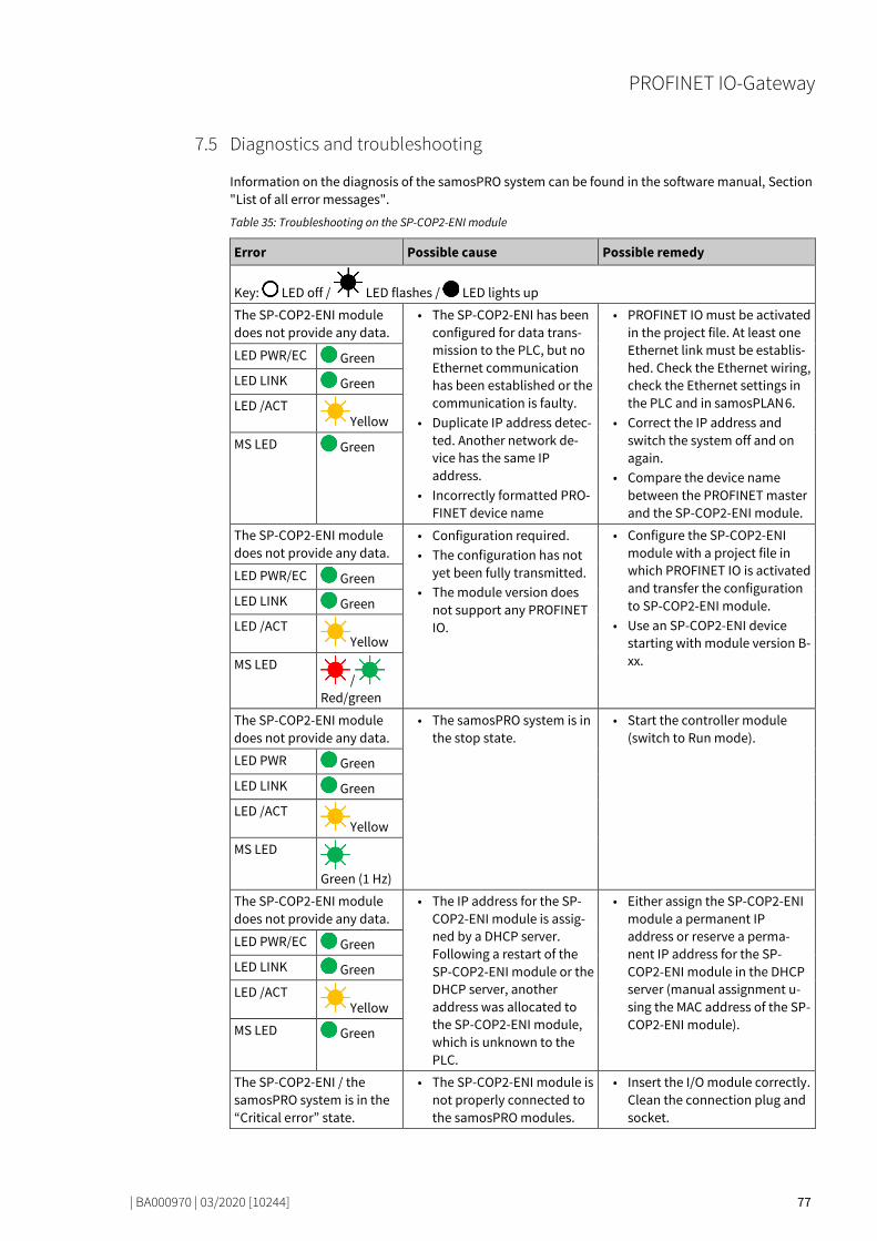
PROFINET IO-Gateway
| BA000970 | 03/2020 [10244] 77
Diagnostics and troubleshooting 79278347
Information on the diagnosis of the samosPRO system can be found in the software manual, Section "List of all error messages".
Table 35: Troubleshooting on the SP-COP2-ENI module
Error Possible cause Possible remedy
Key: LED off / LED flashes / LED lights up
The SP-COP2-ENI module does not provide any data.
• The SP-COP2-ENI has been configured for data trans-mission to the PLC, but no Ethernet communication has been established or the communication is faulty.
• Duplicate IP address detec-ted. Another network de-vice has the same IP address.
• Incorrectly formatted PRO-FINET device name
• PROFINET IO must be activated in the project file. At least one Ethernet link must be establis-hed. Check the Ethernet wiring, check the Ethernet settings in the PLC and in samosPLAN 6.
• Correct the IP address and switch the system off and on again.
• Compare the device name between the PROFINET master and the SP-COP2-ENI module.
LED PWR/EC Green
LED LINK Green
LED /ACT Yellow
MS LED Green
The SP-COP2-ENI module does not provide any data.
• Configuration required. • The configuration has not
yet been fully transmitted. • The module version does
not support any PROFINET IO.
• Configure the SP-COP2-ENI module with a project file in which PROFINET IO is activated and transfer the configuration to SP-COP2-ENI module.
• Use an SP-COP2-ENI device starting with module version B-xx.
LED PWR/EC Green
LED LINK Green
LED /ACT Yellow
MS LED /
Red/green
The SP-COP2-ENI module does not provide any data.
• The samosPRO system is in the stop state.
• Start the controller module (switch to Run mode).
LED PWR Green
LED LINK Green
LED /ACT Yellow
MS LED
Green (1 Hz)
The SP-COP2-ENI module does not provide any data.
• The IP address for the SP-COP2-ENI module is assig-ned by a DHCP server. Following a restart of the SP-COP2-ENI module or the DHCP server, another address was allocated to the SP-COP2-ENI module, which is unknown to the PLC.
• Either assign the SP-COP2-ENI module a permanent IP address or reserve a perma-nent IP address for the SP-COP2-ENI module in the DHCP server (manual assignment u-sing the MAC address of the SP-COP2-ENI module).
LED PWR/EC Green
LED LINK Green
LED /ACT Yellow
MS LED Green
The SP-COP2-ENI / the samosPRO system is in the “Critical error” state.
• The SP-COP2-ENI module is not properly connected to the samosPRO modules.
• Insert the I/O module correctly. Clean the connection plug and socket.
7.5

PROFINET IO-Gateway
| BA000970 | 03/2020 [10244] 78
Error Possible cause Possible remedy
LED PWR Green • The module connection plug is dirty or damaged.
• Another samosPRO module has an internal critical er-ror.
• Switch on the power supply again.
• Check the other samosPRO modules.
LED LINK Green
LED /ACT Yellow
MS LED Red
Deactivation of the PROFINET IO function 79304459
If the SP-COP2-ENI device is started with an activated PROFINET IO function, then this function remains active until the device is switched off.
For this reason, switch the device off after sending a project without PROFINET IO function. This is required, for example, if you convert the gateway function in the samosPRO project from PROFINET IO to Modbus TCP.
State bits 79325323
The PROFINET IO gateway SP-EN-PN sets state bits, which are available in the logic editor of samos-PLAN 6 for processing.
Table 36: Meaning of the state bits SP-EN-PN[0] in the logic editor
Name of the state bits Set to 1, if ... Reset to 0 ...
Output state … Data from slot 16, 17, 18, 19, 20, 32 or 33 was transmitted without error.
… No AR (Application Relation) exists.
Input state … Data from slot 21, 22, 23, 24 or 25 was downloaded from a PLC without error.
… No AR (Application Relation) exists.
Internal state … An AR (Application Relation) is active.
... No AR exists.
An Application Relation (AR) is a clear communication relationship between two communication partners, for example a PLC and a device. The AR is initialized during PLC start-up. Cyclical input and output data, acyclical data using read/write services and alarms are exchanged bidirectionally between the PLC and the device within this AR.
Optimizing performance 79334795
Only use the data blocks from the hardware catalog of the module that you actually need for your application.
Sequence the process data in the routing tables within a data block without gaps (see Layout and content of the tabs [ch. 5.1.3, p. 44]). Then check whether this will enable you to do without the use of individual data blocks from the hardware catalog. This helps to reduce the number of data bytes pe-riodically exchanged in the network.
7.6
7.7
7.8
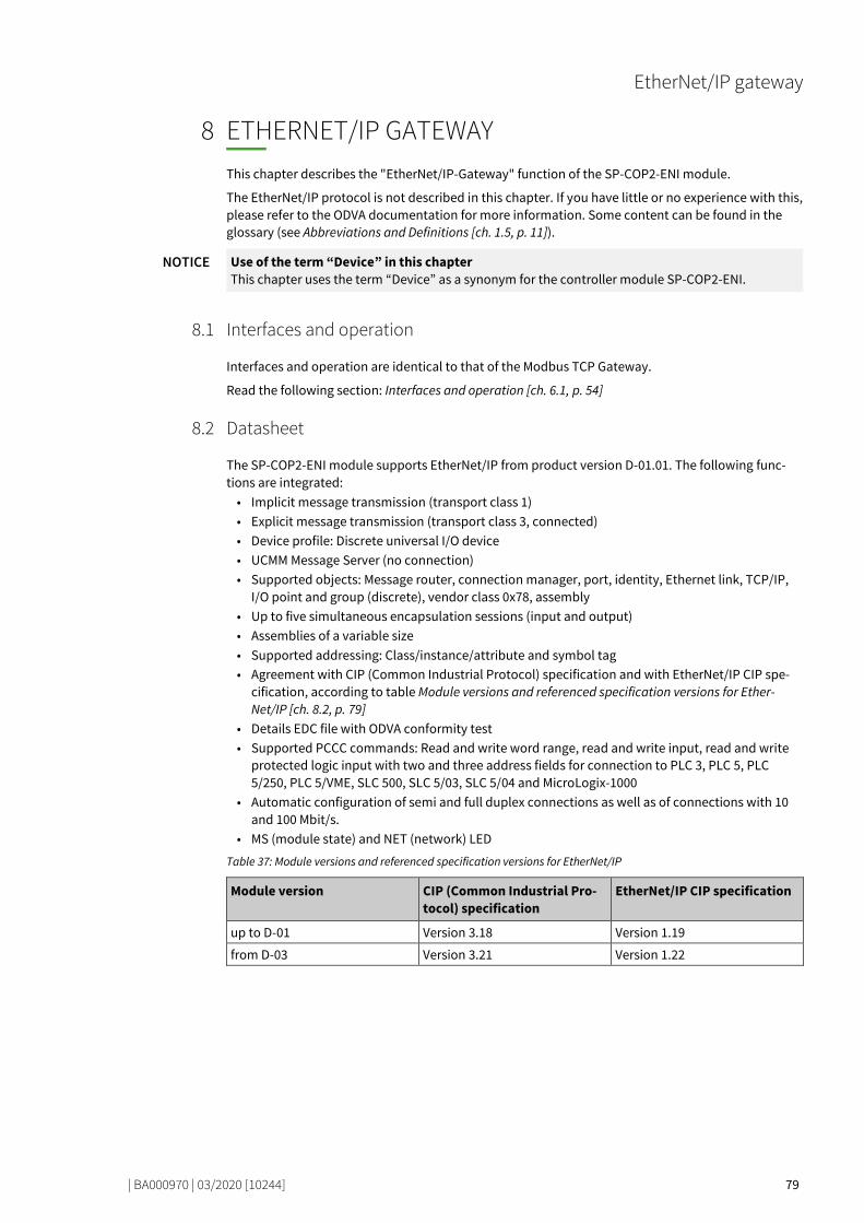
EtherNet/IP gateway
| BA000970 | 03/2020 [10244] 79
ETHERNET/IP GATEWAY
79742603
This chapter describes the "EtherNet/IP-Gateway" function of the SP-COP2-ENI module.
The EtherNet/IP protocol is not described in this chapter. If you have little or no experience with this, please refer to the ODVA documentation for more information. Some content can be found in the glossary (see Abbreviations and Definitions [ch. 1.5, p. 11]).
NOTICE Use of the term “Device” in this chapter This chapter uses the term “Device” as a synonym for the controller module SP-COP2-ENI.
Interfaces and operation 80851595
Interfaces and operation are identical to that of the Modbus TCP Gateway.
Read the following section: Interfaces and operation [ch. 6.1, p. 54]
Datasheet 79755787
The SP-COP2-ENI module supports EtherNet/IP from product version D-01.01. The following func-tions are integrated: • Implicit message transmission (transport class 1) • Explicit message transmission (transport class 3, connected) • Device profile: Discrete universal I/O device • UCMM Message Server (no connection) • Supported objects: Message router, connection manager, port, identity, Ethernet link, TCP/IP,
I/O point and group (discrete), vendor class 0x78, assembly • Up to five simultaneous encapsulation sessions (input and output) • Assemblies of a variable size • Supported addressing: Class/instance/attribute and symbol tag • Agreement with CIP (Common Industrial Protocol) specification and with EtherNet/IP CIP spe-
cification, according to table Module versions and referenced specification versions for Ether-Net/IP [ch. 8.2, p. 79]
• Details EDC file with ODVA conformity test • Supported PCCC commands: Read and write word range, read and write input, read and write
protected logic input with two and three address fields for connection to PLC 3, PLC 5, PLC 5/250, PLC 5/VME, SLC 500, SLC 5/03, SLC 5/04 and MicroLogix-1000
• Automatic configuration of semi and full duplex connections as well as of connections with 10 and 100 Mbit/s.
• MS (module state) and NET (network) LED
Table 37: Module versions and referenced specification versions for EtherNet/IP
Module version CIP (Common Industrial Pro-tocol) specification
EtherNet/IP CIP specification
up to D-01 Version 3.18 Version 1.19
from D-03 Version 3.21 Version 1.22
8
8.1
8.2

EtherNet/IP gateway
| BA000970 | 03/2020 [10244] 80
Basic setup 79776907
Basic configuration of PLC 79787147
This chapter briefly describes the basic configuration of the PLC.
Firstly, install the current EDS file for the SP-COP2-ENI module in your PLC configuration program. You can find the current EDS file on the Internet at https://eshop.wieland-electric.com/. The follo-wing diagram shows you how you can make the setting using the Logix Designer.
Illustration 13: Register the EDS file using the ESD Wizard in the Logix Designer
The article number is "R1.190.1320.0" and can be filtered according to the vendor name "Wieland Electric" or a part of this name.
Illustration 14: Selection of the module type in the Logix Designer
8.3
8.3.1

EtherNet/IP gateway
| BA000970 | 03/2020 [10244] 81
In the Internet Protocol tab in the Logix Designer, select Manually configure IP settings. Select the required IPv4 address and the appropriate network mask.
Illustration 15: IPv4 setting for the device in the Logix Designer

EtherNet/IP gateway
| BA000970 | 03/2020 [10244] 82
The SP-COP2-ENI module is a General Purpose Discrete I/O Device. For quick installation, use the connection Logic Output (1 to 400) and Logic/Physical Input, if your PLC supports implicit messa-ge transmission. The following figure shows the appropriate dialog in the Logix Designer.
Illustration 16: Basic connection selected in the Logix Designer
This connection comprises up to 50 bytes for data transmission from the PLC to the SP-COP2-ENI module (assembly instance 37). This connection comprises up to 67 bytes for data transmission from the SP-COP2-ENI module to the PLC (assembly instance 57). The following table offers an over-view of these data bytes.
Table 38: Data of the class 1 connection “Logic output (1 to 400) and logic/physical input”
Instance Byte Access Data type Description Size Data range
37 0 to 49 Write, read BYTE[50] Output bytes, configuration via Input data block 1 to 5 in samosPLAN 6 (More [ch. 8.5.2.1, p. 106])
1 to 50 Bytes 0 to 0xff
57 0 to 49 Read BYTE[50] Input bytes, configuration via Output data block 1 in samos-PLAN 6 (More [ch. 8.5.3.1, p. 107])
1 to 50 Bytes 0 to 0xff
50 to 65 Read BYTE[16] Bits of the input terminals (instance 401 to 528 of attribu-te 3 class 8, currently not listed in samosPLAN 6) (More [ch. 8.5.3.1, p. 107])
1 to 16 Bytes 0 to 0xff
66 Read BYTE Bit 7: Input state Bit 6: Output state (currently not listed in samos-PLAN 6)
1 byte 0x00, 0x40, 0x80, 0xc0

EtherNet/IP gateway
| BA000970 | 03/2020 [10244] 83
Other connections supported by the SP-COP2-ENI module are listed in the following table. You can find information on these assembly instances in the table "Overview of assembly databytes [ch. 8.5.1, p. 104]".
Table 39: Class 1 connections supported by the SP-COP2-ENI module
Name of the connection Assembly for data from the PLC to SP-COP (O→T)
Assembly for data from SP-COP to the PLC (T→O)
Logic output (1 to 400) and logic/physical input 37 57
Logic output (1 to 400) and logic/state/system mode assembly
37 167
Logic output (81 to 400) and logic/physical input 138 57
Logic output (81 to 400) and logic/state/system mode assembly
138 167
Logic output (161 to 400) and logic/physical input 139 57
Logic output (161 to 400) and logic/state/system mode assembly
139 167
Logic output (241 to 400) and logic/physical input 140 57
Logic output (241 to 400) and logic/state/system mode assembly
140 167
Logic output (321 to 400) and logic/physical input 141 57
Logic output (321 to 400) and logic/state/system mode assembly
141 167
Logic/physical input (“Listen only”) 199 57
Logic/state/system mode assembly (“Listen only”) 199 167
Logic/physical input (“Input only”) 198 57
Logic/state/system mode assembly (“Input only”) 198 167
Connection point 199 (= 0xc7) is used for Listen Only and connection point 198 (= 0xc6) for Input Only. Both possess a data size of zero. This means that the PLC does not make any data available for the SP-COP2-ENI module.
If the PLC only requires process data from the SP-COP module, the user is recommended to use a connection with Input Only.

EtherNet/IP gateway
| BA000970 | 03/2020 [10244] 84
Basic configuration of the controller module 79825419
The integrated gateway SP-EN-IP (EtherNet/IP gateway) is a constituent part of the SP-COP2-ENI module.
Activating the gateway You can activate the integrated gateway in the configuration dialog of the SP-COP2-ENI module in the Properties docking window:
Illustration 17: Activation of EtherNet/IP in samosPLAN 6
NOTICE Selection of the SP-EN-IP gateway is possible for modules of type SP-COP2-ENI from version D-01.01.
Adapting the IPv4 data The IPv4 data of the SP-COP2-ENI module can be adapted to the PLC settings in samosPLAN 6.
Requirement During transmission of the IPv4 data, the device must not be in Run (Execute) mode. The command bar must be displayed on the left above the Start command, as shown in the following illustrations. If this is not the case, stop the device via the Stop button.
Required window layout
Illustration 18: Setting of the IPv4 device data in samosPLAN 6
8.3.2
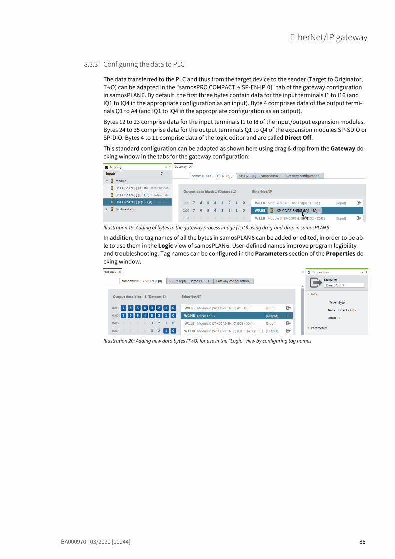
EtherNet/IP gateway
| BA000970 | 03/2020 [10244] 85
Configuring the data to PLC 79846795
The data transferred to the PLC and thus from the target device to the sender (Target to Originator, T→O) can be adapted in the "samosPRO COMPACT → SP-EN-IP[0]" tab of the gateway configuration in samosPLAN 6. By default, the first three bytes contain data for the input terminals I1 to I16 (and IQ1 to IQ4 in the appropriate configuration as an input). Byte 4 comprises data of the output termi-nals Q1 to A4 (and IQ1 to IQ4 in the appropriate configuration as an output).
Bytes 12 to 23 comprise data for the input terminals I1 to I8 of the input/output expansion modules. Bytes 24 to 35 comprise data for the output terminals Q1 to Q4 of the expansion modules SP-SDIO or SP-DIO. Bytes 4 to 11 comprise data of the logic editor and are called Direct Off.
This standard configuration can be adapted as shown here using drag & drop from the Gateway do-cking window in the tabs for the gateway configuration:
Illustration 19: Adding of bytes to the gateway process image (T→O) using drag-and-drop in samosPLAN 6
In addition, the tag names of all the bytes in samosPLAN 6 can be added or edited, in order to be ab-le to use them in the Logic view of samosPLAN 6. User-defined names improve program legibility and troubleshooting. Tag names can be configured in the Parameters section of the Properties do-cking window.
Illustration 20: Adding new data bytes (T→O) for use in the "Logic" view by configuring tag names
8.3.3

EtherNet/IP gateway
| BA000970 | 03/2020 [10244] 86
Configuring the usage of data from PLC 79867787
Data transmitted by the PLC and thus by the sender to the target device (Originator to Target, O→T) can be named in the "SP-EN-IP [0] → samosPRO COMPACT" tab for the gateway configuration in sa-mosPLAN 6. By default, the logic values Direct On 0 to Direct On 3 are assigned to the four first bytes. The names Data bit 0 to Data bit 7 are assigned to each bit as standard. Each bit can be used in the Logic view of samosPLAN 6 as an unsafe input element, such as a Restart button or as a signal lamp.
Additional input elements for gateway data can be added as necessary by the configuration of addi-tional tag names.
Illustration 21: Adding of a new data byte (T→O) for use in the logic editor by configuring the tag name.
Illustration 22: Adding gateway data elements to the logic editor in samosPLAN 6 via drag & drop
8.3.4

EtherNet/IP gateway
| BA000970 | 03/2020 [10244] 87
Supported CIP Objects 79883019
Identity Object 79893259
The identity object is required for all EtherNet/IP-based products. Instance 1, attribute 1 stands for the Vendor ID. Wieland Electric GmbH is listed by the ODVA using the value 314.
Instance 1, attribute 2 stands for the device types. The Open Type Code 0x07 stands for a discrete universal I/O device.
Instance 1, attribute 3 stands for the product code. It is of the type UNIT and thus comprises 2 bytes.
The decimal value is always constant at 1320.
Instance 1, attribute 4 stands for the revision, that means the main and supplementary firmware version of the SP-COP2-ENI module, which you can find in the samosPLAN 6 software as the Diag-nostics version. You can see both details in the Properties docking window, if you select the con-troller module in the Modules docking window after you have connected to the station.
Illustration 23: Display of diagnostic version and hardware version in configuration dialog of the controller module
Instance 1, attribute 5 standard for the current state of the overall device. The data range is listed in the Device state values table in class 1, instance 1, attribute 5 [ch. 8.4.1, p. 88].
Instance 1, attribute 6 stands for the serial number of the device, which can be found under the hardware configuration in samosPLAN 6. Instance 1, attribute 7 stands for the product name SP-COP2-ENI.
8.4
8.4.1

EtherNet/IP gateway
| BA000970 | 03/2020 [10244] 88
Table 40: Overview of the identity class (0x01) supported by the SP-COP2-ENI module
Class Instance Attribute Access Data type Description Data range
1 0 = Class 1 Read UINT Revision 1
1 0 = Class 2 Read UINT Max. instance 1
1 0 = Class 3 Read UINT Number of instances 1
1 0 = Class 6 Read UINT Max. class attribute ID 7
1 0 = Class 7 Read UINT Max. instance attribute ID 7
1 1 1 Read UINT Vendor ID 314 = 0x13a
1 1 2 Read UINT Device type 0x07
1 1 3 Read UINT Product code [ch. 8.4.8.3, p. 100] 1320
1 1 4 Read USINT[2] Revision, software version The “left” byte is the main section and is transmitted first
1, 1 to 99, 99
1 1 5 Read WORD Device state See next table
1 1 6 Read UDINT Serial number 16010001 to 99539999
1 1 7 Read SHORT_ STRING
Product name SP-COP2-ENI
Table 41: Device state values of the SP-COP2-ENI module in class 1, instance 1, attribute 5
State value Description Possible system mode
0b0000 xxxx xxxx 0x01 There is at least one EtherNet/IP connec-tion to a PLC (owner of the connection)
4 = Idle 5 = Run 7 = Critical error 21 = Force mode
0b0000 xxxx 0000 010x Device is configured 4 = Idle 5 = Run 7 = Critical error 21 = Force mode
0b0000 0001 0000 0x0x Low, removable error 4 = Idle 5 = Run 21 = Force mode
0b0000 0010 0000 0x0x Low, non-removable error 4 = Idle 5 = Run 21 = Force mode
0b0000 0100 0000 0x0x Serious, removable error 1 = Init 2 = Configuration required 3 = Configuration running
0b0000 1000 0000 0x0x Serious, non-removable error 7 = Critical error

EtherNet/IP gateway
| BA000970 | 03/2020 [10244] 89
Assembly Object 79954059
All the data of the Class 1 connections are also provided by the Assembly object. The following table offers an overview of this assembly object.
Further information: • Table Overview of assembly databytes of the SP-COP2-ENI module [ch. 8.5.1, p. 104] • Figure Data flow with usage of Assembly Instances [ch. 8.6.2, p. 109]
(Shows the data flow in front of the PLC to the module SP-COP2-ENI and back from the point of view of the individual assemblies.)
Table 42: Overview of the assembly class (0x04) supported by the SP-COP2-ENI module
Class Instance Attribute Access Data type Description Data range
4 0 = Class 1 Read UINT Revision of the class 2
4 0 = Class 2 Read UINT Max. instance 167
4 0 = Class 3 Read UINT Number of instances 7
4 0 = Class 6 Read UINT Max. class attribute ID 7
4 0 = Class 7 Read UINT Max. instance attribute ID 4
4 37 1 Read UINT Number of members 0
4 37 3 Read, write
BYTE[50] Bits of the logic outputs [ch. 8.5.2, p. 106] (Instance 1 to 400 of Class 9)
See 1)
4 37 4 Read UINT Number of data bytes 50
4 57 1 Read UINT Number of members 0
4 57 3 Read BYTE[67] Input bits (Instance 1 to 528 of Class 8)
See 1)
4 57 4 Read UINT Number of data bytes 67
4 138 1 Read UINT Number of members 0
4 138 3 Read, write
BYTE[40] Bits of the logic outputs [ch. 8.5.2, p. 106] (Instance 81 to 400 of Class 9)
See 1)
4 138 4 Read UINT Number of data bytes 40
4 139 1 Read UINT Number of members 0
4 139 3 Read, write
BYTE[30] Bits of the logic outputs [ch. 8.5.2, p. 106] (Instance 161 to 400 of Class 9)
See 1)
4 139 4 Read UINT Number of data bytes 30
4 140 1 Read UINT Number of members 0
4 140 3 Read, write
BYTE[20] Bits of the logic outputs [ch. 8.5.2, p. 106] (Instance 241 to 400 of Class 9)
See 1)
4 140 4 Read UINT Number of data bytes 20
4 141 1 Read UINT Number of members 0
4 141 3 Read, write
BYTE[10] Bits of the logic outputs [ch. 8.5.2, p. 106] (Instance 321 to 400 of Class 9)
See 1)
4 141 4 Read UINT Number of data bytes 10
4 167 1 Read UINT Number of members 0
4 167 3 Read BYTE[112] Bits of the logic inputs, mode and state bytes (More [ch. 8.5.3.2, p. 107])
See 1)
4 167 4 Read UINT Number of data bytes 112 1)See: Table Overview of assembly databytes of the SP-COP2-ENI module [ch. 8.5.1, p. 104]
8.4.2

EtherNet/IP gateway
| BA000970 | 03/2020 [10244] 90
Discrete Input Point Object 79995019
The discrete input point objects are part of the device profile Discrete universal I/O device.
If an error occurs at the terminal input of a specific instance between 401 and 528 and the SP-COP2-ENI module is in Run mode, the value of the instance attribute 4 equals 1. In all other cases, the va-lue equals 0.
Table 43: Overview of the discrete input point objects (0x08) supported by the SP-COP2-ENI module
Class Instance Attribu-te
Access Data type Description Data range
8 0 = Class 1 Read UINT Revision of the class 2
8 0 = Class 2 Read UINT Max. instance 584
8 0 = Class 3 Read UINT Number of instances 400 + 128 + 56 Logic + input + output
8 0 = Class 6 Read UINT Max. class attribute ID 7
8 0 = Class 7 Read UINT Max. instance attribute ID 4
8 1 to 400 and 529 to 584
1 Read USINT Number of attributes 3
8 401 to 528 1 Read USINT Number of attributes 4
8 1 to 528 2 Read USINT[4] List of support attributes 1, 2, 3, 4
8 529 to 584 2 Read USINT[3] List of support attributes 1, 2, 3
8 1 to 400 3 Read BOOL The value of the input bit, configured by the output data set 1 in samos-PLAN 6, stands for the data transferred by the logic of the controller module to the PLC.
0 = Off, 1 = On
8 1 to 400 4 Read BOOL State of output data set 1 0 = OK
8 401 to 416 3 Read BOOL Value of terminals I1 to I16 of the SP-COP2-ENI module
0, 1
8 401 to 416 4 Read BOOL State of terminals I1 to I16 of the SP-COP2-ENI module
0, 1
8 417 to 420 3 Read BOOL Value of terminals IQ1 to IQ4 of the SP-COP2-ENI module when configured as an input
0, 1
8 417 to 420 4 Read BOOL State of terminals IQ1 to IQ4 of the SP-COP2-ENI module when configured as an input
0, 1
8 421 to 430 3 Read BOOL Reserved 0
8 431 3 Read BOOL Value of B1 Voltage is... 0 = Outside the tolerance 1 = Within the tolerance
8 432 3 Read BOOL Value of B2 Voltage is... 0 = Outside the tolerance 1 = Within the tolerance
8 421 to 432 4 Read BOOL Reserved 0
8.4.3
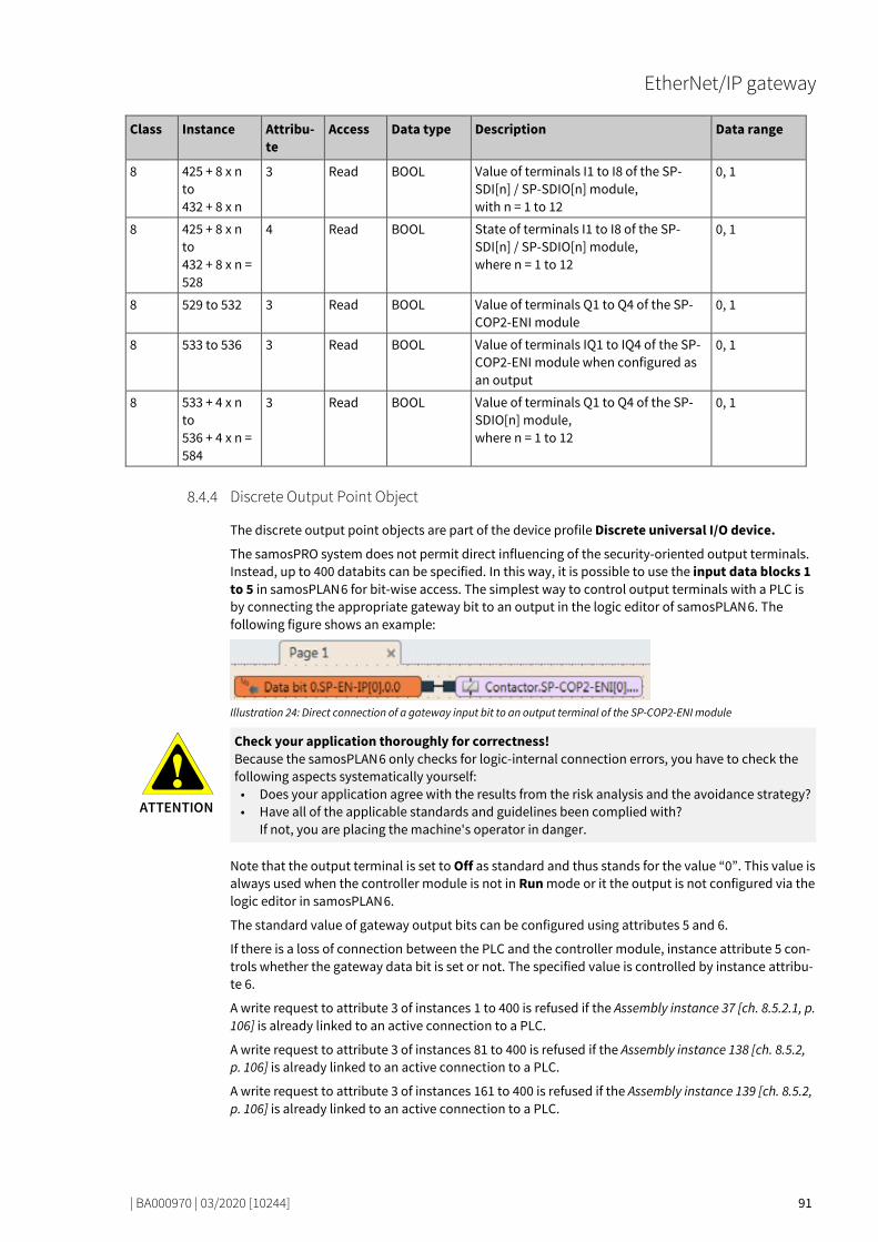
EtherNet/IP gateway
| BA000970 | 03/2020 [10244] 91
Class Instance Attribu-te
Access Data type Description Data range
8 425 + 8 x n to 432 + 8 x n
3 Read BOOL Value of terminals I1 to I8 of the SP-SDI[n] / SP-SDIO[n] module, with n = 1 to 12
0, 1
8 425 + 8 x n to 432 + 8 x n = 528
4 Read BOOL State of terminals I1 to I8 of the SP-SDI[n] / SP-SDIO[n] module, where n = 1 to 12
0, 1
8 529 to 532 3 Read BOOL Value of terminals Q1 to Q4 of the SP-COP2-ENI module
0, 1
8 533 to 536 3 Read BOOL Value of terminals IQ1 to IQ4 of the SP-COP2-ENI module when configured as an output
0, 1
8 533 + 4 x n to 536 + 4 x n = 584
3 Read BOOL Value of terminals Q1 to Q4 of the SP-SDIO[n] module, where n = 1 to 12
0, 1
Discrete Output Point Object 80031755
The discrete output point objects are part of the device profile Discrete universal I/O device.
The samosPRO system does not permit direct influencing of the security-oriented output terminals. Instead, up to 400 databits can be specified. In this way, it is possible to use the input data blocks 1 to 5 in samosPLAN 6 for bit-wise access. The simplest way to control output terminals with a PLC is by connecting the appropriate gateway bit to an output in the logic editor of samosPLAN 6. The following figure shows an example:
Illustration 24: Direct connection of a gateway input bit to an output terminal of the SP-COP2-ENI module
ATTENTION
Check your application thoroughly for correctness! Because the samosPLAN 6 only checks for logic-internal connection errors, you have to check the following aspects systematically yourself:
• Does your application agree with the results from the risk analysis and the avoidance strategy? • Have all of the applicable standards and guidelines been complied with?
If not, you are placing the machine's operator in danger.
Note that the output terminal is set to Off as standard and thus stands for the value “0”. This value is always used when the controller module is not in Run mode or it the output is not configured via the logic editor in samosPLAN 6.
The standard value of gateway output bits can be configured using attributes 5 and 6.
If there is a loss of connection between the PLC and the controller module, instance attribute 5 con-trols whether the gateway data bit is set or not. The specified value is controlled by instance attribu-te 6.
A write request to attribute 3 of instances 1 to 400 is refused if the Assembly instance 37 [ch. 8.5.2.1, p. 106] is already linked to an active connection to a PLC.
A write request to attribute 3 of instances 81 to 400 is refused if the Assembly instance 138 [ch. 8.5.2, p. 106] is already linked to an active connection to a PLC.
A write request to attribute 3 of instances 161 to 400 is refused if the Assembly instance 139 [ch. 8.5.2, p. 106] is already linked to an active connection to a PLC.
8.4.4
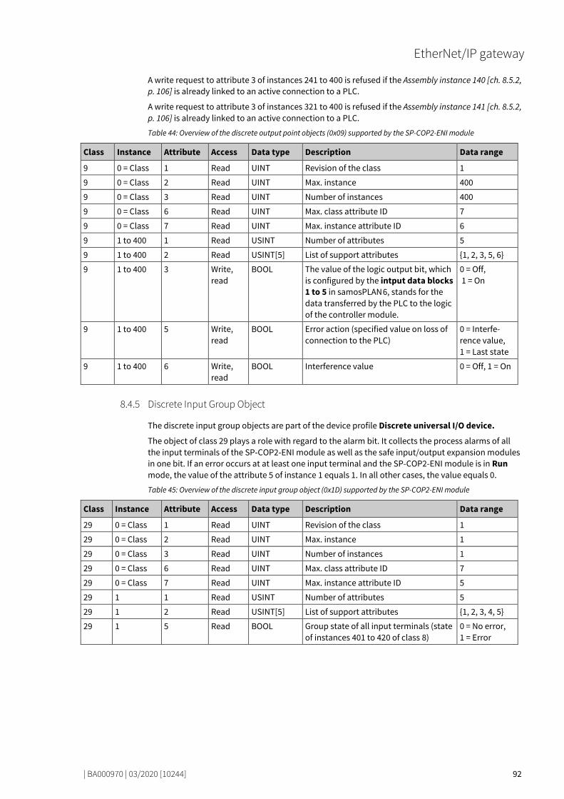
EtherNet/IP gateway
| BA000970 | 03/2020 [10244] 92
A write request to attribute 3 of instances 241 to 400 is refused if the Assembly instance 140 [ch. 8.5.2, p. 106] is already linked to an active connection to a PLC.
A write request to attribute 3 of instances 321 to 400 is refused if the Assembly instance 141 [ch. 8.5.2, p. 106] is already linked to an active connection to a PLC.
Table 44: Overview of the discrete output point objects (0x09) supported by the SP-COP2-ENI module
Class Instance Attribute Access Data type Description Data range
9 0 = Class 1 Read UINT Revision of the class 1
9 0 = Class 2 Read UINT Max. instance 400
9 0 = Class 3 Read UINT Number of instances 400
9 0 = Class 6 Read UINT Max. class attribute ID 7
9 0 = Class 7 Read UINT Max. instance attribute ID 6
9 1 to 400 1 Read USINT Number of attributes 5
9 1 to 400 2 Read USINT[5] List of support attributes 1, 2, 3, 5, 6
9 1 to 400 3 Write, read
BOOL The value of the logic output bit, which is configured by the intput data blocks 1 to 5 in samosPLAN 6, stands for the data transferred by the PLC to the logic of the controller module.
0 = Off, 1 = On
9 1 to 400 5 Write, read
BOOL Error action (specified value on loss of connection to the PLC)
0 = Interfe-rence value, 1 = Last state
9 1 to 400 6 Write, read
BOOL Interference value 0 = Off, 1 = On
Discrete Input Group Object 80068491
The discrete input group objects are part of the device profile Discrete universal I/O device.
The object of class 29 plays a role with regard to the alarm bit. It collects the process alarms of all the input terminals of the SP-COP2-ENI module as well as the safe input/output expansion modules in one bit. If an error occurs at at least one input terminal and the SP-COP2-ENI module is in Run mode, the value of the attribute 5 of instance 1 equals 1. In all other cases, the value equals 0.
Table 45: Overview of the discrete input group object (0x1D) supported by the SP-COP2-ENI module
Class Instance Attribute Access Data type Description Data range
29 0 = Class 1 Read UINT Revision of the class 1
29 0 = Class 2 Read UINT Max. instance 1
29 0 = Class 3 Read UINT Number of instances 1
29 0 = Class 6 Read UINT Max. class attribute ID 7
29 0 = Class 7 Read UINT Max. instance attribute ID 5
29 1 1 Read USINT Number of attributes 5
29 1 2 Read USINT[5] List of support attributes 1, 2, 3, 4, 5
29 1 5 Read BOOL Group state of all input terminals (state of instances 401 to 420 of class 8)
0 = No error, 1 = Error
8.4.5

EtherNet/IP gateway
| BA000970 | 03/2020 [10244] 93
Discrete Output Group Object 80094091
The discrete output group objects are part of the device profile Discrete universal I/O device.
The object of class 30 plays a role with regard to the alarm bit. It collects the process alarms of all the output terminals of a SP-COP2-ENI or SP-SDIO module in one bit. If an error occurs at at least one output terminal and the SP-COP2-ENI module is in Run mode, the value of the attribute 5 of in-stance 1 equals 1. If the SP-COP2-ENI module is in Critical error mode, the attribute value is also 1. In all other cases, the value equals 0.
Table 46: Overview of the discrete output group object (0x1D) supported by the SP-COP2-ENI module
Class Instance Attribute Access Data type Description Data range
30 0 = Class 1 Read UINT Revision of the class 1
30 0 = Class 2 Read UINT Max. instance 1
30 0 = Class 3 Read UINT Number of instances 1
30 0 = Class 6 Read UINT Max. class attribute ID 7
30 0 = Class 7 Read UINT Max. instance attribute ID 6
30 1 1 Read USINT Number of attributes 6
30 1 2 Read USINT[6] List of support attributes 1, 2, 3, 4, 5, 6
30 1 3 Read USINT Number of bound instances 56
30 1 4 Read UINT[56] Bound instances 1, ..., 56
30 1 5 Read BOOL Group state of all output terminals (state of instances 529 to 584 of class 8)
0 = No error, 1 = Error
8.4.6
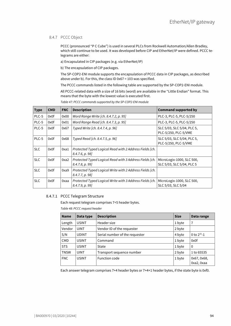
EtherNet/IP gateway
| BA000970 | 03/2020 [10244] 94
PCCC Object 80119691
PCCC (pronounced “P C Cube”) is used in several PLCs from Rockwell Automation/Allen Bradley, which still continue to be used. It was developed before CIP and EtherNet/IP were defined. PCCC te-legrams are either:
a) Encapsulated in CIP packages (e.g. via EtherNet/IP)
b) The encapsulation of CIP packages.
The SP-COP2-ENI module supports the encapsulation of PCCC data in CIP packages, as described above under b). For this, the class ID 0x67 = 103 was specified.
The PCCC commands listed in the following table are supported by the SP-COP2-ENI module.
All PCCC-related data with a size of 16 bits (word) are available in the “Little Endian” format. This means that the byte with the lowest value is executed first.
Table 47: PCCC commands supported by the SP-COP2-ENI module
Type CMD FNC Description Command supported by
PLC-5 0x0f 0x00 Word Range Write [ch. 8.4.7.2, p. 95] PLC-3, PLC-5, PLC-5/250
PLC-5 0x0f 0x01 Word Range Read [ch. 8.4.7.3, p. 95] PLC-3, PLC-5, PLC-5/250
PLC-5 0x0f 0x67 Typed Write [ch. 8.4.7.4, p. 96] SLC 5/03, SLC 5/04, PLC 5, PLC-5/250, PLC-5/VME
PLC-5 0x0f 0x68 Typed Read [ch. 8.4.7.5, p. 96] SLC 5/03, SLC 5/04, PLC 5, PLC-5/250, PLC-5/VME
SLC 0x0f 0xa1 Protected Typed Logical Read with 2 Address Fields [ch. 8.4.7.6, p. 98]
SLC 0x0f 0xa2 Protected Typed Logical Read with 3 Address Fields [ch. 8.4.7.8, p. 99]
MicroLogix-1000, SLC 500, SLC 5/03, SLC 5/04, PLC 5
SLC 0x0f 0xa9 Protected Typed Logical Write with 2 Address Fields [ch. 8.4.7.7, p. 98]
SLC 0x0f 0xaa Protected Typed Logical Write with 3 Address Fields [ch. 8.4.7.9, p. 99]
MicroLogix-1000, SLC 500, SLC 5/03, SLC 5/04
80135307
PCCC Telegram Structure Each request telegram comprises 7+5 header bytes.
Table 48: PCCC request header
Name Data type Description Size Data range
Length USINT Header size 1 byte 7
Vendor UINT Vendor ID of the requester 2 byte
S/N UDINT Serial number of the requester 4 byte 0 to 232-1
CMD USINT Command 1 byte 0x0f
STS USINT State 1 byte 0
TNSW UINT Transport sequence number 2 byte 1 to 65535
FNC USINT Function code 1 byte 0x67, 0x68, 0xa2, 0xaa
Each answer telegram comprises 7+4 header bytes or 7+4+1 header bytes, if the state byte is 0xf0.
8.4.7
8.4.7.1

EtherNet/IP gateway
| BA000970 | 03/2020 [10244] 95
Table 49: PCCC reply header
Name Data type Meaning Size Data range
Length USINT Header size 1 Byte 7
Vendor UINT Vendor ID of requester 2 Byte
S/N UDINT Serial number of requester 4 Byte 0 to 232-1
CMD USINT Command of requester plus Bit 6 set 1 Byte 0x4f
STS USINT Status 1 Byte 0x00, 0x10, 0xf0
TNSW UINT Transport sequence number 2 Byte 1 to 65535
EXT STS USINT Extended Status, only present if STS = 0xf0 0 to 1 Byte
80163083
Word Range Write The SP-COP2-ENI module supports “Write PLC-5 word range” according to the following table:
Table 50: Data structure of PLC-5 Word Range Write
Name Data type Meaning Data range
Packet offset UINT Offset in number of elements
Total Transaction UINT number of elements in transaction
Address BYTE[m] PLC-5 system address, m >= 2
Payload UINT[n] 2 x n = Data byte count 0 to 65535
The answer of the SP-COP2-ENI module does not contain any data, only a state. 80188939
Word Range Read The SP-COP2-ENI module supports “Read PLC-5 word range” according to the following table:
Table 51: Read request data structure of PLC-5 word range
Name Data type Description Data range
Packet offset UINT Offset as number of elements
Total Transaction UINT Number of elements in the transaction 0 to value depen-dent on the as-sembly size
Address BYTE[m] PLC-5 system address, m >= 2 “0” to “:”, “A” to “Z”, “a” to “z”
Size UINT Number of elements to be returned
Table 52: Feedback to the SP-COP2-ENI module of Read PLC-5 word range
Name Data type Description Data range
Payload UINT[n] 2•n = number of data bytes (up to 244 bytes)
0 to 65535
80214923
8.4.7.2
8.4.7.3

EtherNet/IP gateway
| BA000970 | 03/2020 [10244] 96
Typed Write The SP-COP2-ENI module supports “Write PLC-5 input” according to the following table:
Table 53: Write data structure of PLC-5 input
Name Data type Description Data range
Packet offset UINT Offset as number of elements
Total Transaction UINT Number of elements in the transaction
Address BYTE[m] PLC-5 system address, m >= 2 See next table
Type ID BYTE[n] Data type and size, n >= 1
The answer of the SP-COP2-ENI module does not contain any data, only a state, see table PCCC reply header [ch. 8.4.7.1, p. 95]. The UINT data format corresponds to writing the format of the word range.
Table 54: Write address structure of PLC-5 input
Address Data type Number of elements
Description Data range
$N37:x UINT[n] n Output assembly of the device profile Discrete universal I/O device, x = 0 to 24, n = 25 - x
0 to 65535
$N138:x UINT[n] n Output assembly of the logic output, confi-gured via the input data block 2 to 5 in samosPLAN 6, x = 0 to 19, n = 20 – x
0 to 65535
$N139:x UINT[n] n Output assembly of the logic output, confi-gured via the input data block 3 to 5 in samosPLAN 6, x = 0 to 14, n = 15 – x
0 to 65535
$N140:x UINT[n] n Output assembly of the logic output, confi-gured via the input data block 4 to 5 in samosPLAN 6, x = 0 to 9, n = 10 – x
0 to 65535
$N141:x UINT[n] n Output assembly of the logic output, confi-gured via the input data block 4 to 5 in samosPLAN 6, x = 0 to 4, n = 5 – x
0 to 65535
The data range of the number of elements is relative to the assembly sizes. See the table Overview of assembly databytes of the SP-COP2-ENI module [ch. 8.5.1, p. 104]
80232075
Typed Read The SP-COP2-ENI module supports “Read PLC-5 input” according to the following table:
Table 55: Read request data structure of PLC-5 word range
Name Data type Description Data range
Packet offset UINT Offset in number of elements
Total Transaction UINT Number of elements in the transac-tion
0 to value dependent on the assembly size
Address BYTE[m] PLC-5 system address, m >= 2 “0” to “:”, “A” to “Z”, “a” to “z”
Size UINT Number of elements to be returned
The answer of the SP-COP2-ENI module is listed in the following table. The first byte of the type ID is 0x9a = 0b1001 1010, meaning that the data type is given in the following byte and the data size in the
8.4.7.4
8.4.7.5
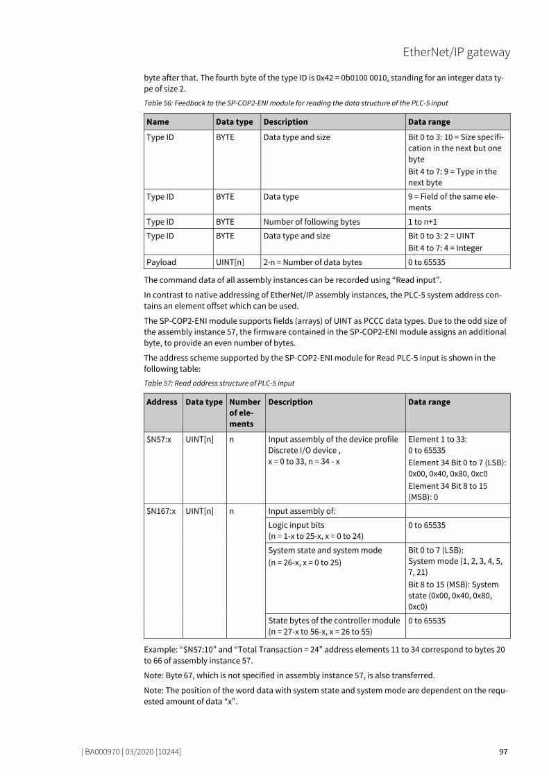
EtherNet/IP gateway
| BA000970 | 03/2020 [10244] 97
byte after that. The fourth byte of the type ID is 0x42 = 0b0100 0010, standing for an integer data ty-pe of size 2.
Table 56: Feedback to the SP-COP2-ENI module for reading the data structure of the PLC-5 input
Name Data type Description Data range
Type ID BYTE Data type and size Bit 0 to 3: 10 = Size specifi-cation in the next but one byte Bit 4 to 7: 9 = Type in the next byte
Type ID BYTE Data type 9 = Field of the same ele-ments
Type ID BYTE Number of following bytes 1 to n+1
Type ID BYTE Data type and size Bit 0 to 3: 2 = UINT Bit 4 to 7: 4 = Integer
Payload UINT[n] 2⋅n = Number of data bytes 0 to 65535
The command data of all assembly instances can be recorded using “Read input”.
In contrast to native addressing of EtherNet/IP assembly instances, the PLC-5 system address con-tains an element offset which can be used.
The SP-COP2-ENI module supports fields (arrays) of UINT as PCCC data types. Due to the odd size of the assembly instance 57, the firmware contained in the SP-COP2-ENI module assigns an additional byte, to provide an even number of bytes.
The address scheme supported by the SP-COP2-ENI module for Read PLC-5 input is shown in the following table:
Table 57: Read address structure of PLC-5 input
Address Data type Number of ele-ments
Description Data range
$N57:x UINT[n] n Input assembly of the device profile Discrete I/O device , x = 0 to 33, n = 34 - x
Element 1 to 33: 0 to 65535 Element 34 Bit 0 to 7 (LSB): 0x00, 0x40, 0x80, 0xc0 Element 34 Bit 8 to 15 (MSB): 0
$N167:x UINT[n] n Input assembly of:
Logic input bits (n = 1-x to 25-x, x = 0 to 24)
0 to 65535
System state and system mode (n = 26-x, x = 0 to 25)
Bit 0 to 7 (LSB): System mode (1, 2, 3, 4, 5, 7, 21) Bit 8 to 15 (MSB): System state (0x00, 0x40, 0x80, 0xc0)
State bytes of the controller module (n = 27-x to 56-x, x = 26 to 55)
0 to 65535
Example: “$N57:10” and “Total Transaction = 24” address elements 11 to 34 correspond to bytes 20 to 66 of assembly instance 57.
Note: Byte 67, which is not specified in assembly instance 57, is also transferred.
Note: The position of the word data with system state and system mode are dependent on the requ-ested amount of data “x”.

EtherNet/IP gateway
| BA000970 | 03/2020 [10244] 98
80250763
Protected Typed Logical Read with 2 Address Fields The SP-COP2-ENI module supports “Read SLC-protected logic input” according to the following tab-le:
Table 58: Request data structure for Read SLC-protected logic input with two address fields
Name Data type Description Data range
Byte size USINT Number of data bytes to be read
Assembly instance 37: 0 to 50 Assembly instance 57: 0 to 67 Assembly instance 167: 0 to 112
File number USINT Assembly instance ID 37, 57, 167
File type USINT Data type 0x89 = Integer data
Element number USINT Offset = ID of the first ele-ment of the answer
Assembly instance 37: 0 to 24 – Size/2 Assembly instance 57: 0 to 33 – Size/2 Assembly instance 167: 0 to 55 – Size/2
Table 59: Feedback to the SP-COP2-ENI module for Read SLC-protected logic input with two address fields
Name Data type Description Data range
Payload UINT[n] 2⋅n = Number of data bytes
0 to 65535
80266379
Protected Typed Logical Write with 2 Address Fields The SP-COP2-ENI module supports “Write SLC-protected logic input” according to the following tab-le:
No support is required for assembly instances 138 to 141. The offset, i.e. the first byte, is instead specified by the element number.
Table 60: Request data structure for Write SLC-protected logic input with two address fields
Name Data type Description Data range
Byte size USINT Number of data bytes to be written 0 to 50
File number USINT Assembly instance ID 37
File type USINT Data type 0x89 = Integer data
Element num-ber
USINT Offset = ID of the first element to be sent back
0 to 24 – Size/2
Payload UINT[n] n = Size/2 0 to 65535
80279691
8.4.7.6
8.4.7.7

EtherNet/IP gateway
| BA000970 | 03/2020 [10244] 99
Protected Typed Logical Read with 3 Address Fields The SP-COP2-ENI module supports “Read SLC-protected logic input” according to the following tab-le:
Table 61: Request data structure for Read SLC-protected logic input with three address fields
Name Data type Description Data range
Size USINT Number of data bytes to be read
Assembly instance 37: 0 to 50 Assembly instance 57: 0 to 67 Assembly instance 167: 0 to 112
File number USINT Assembly instance ID 37, 57, 167
File type USINT Data type 0x89 = Integer data
Element number USINT Offset = ID of the first element of the answer
Assembly instance 37: 0 to 24 – Size/2 Assembly instance 57: 0 to 33 – Size/2 Assembly instance 167: 0 to 55 – Size/2
Subelement USINT Doesn’t matter 0 to 254 (for number of bytes 1)
80292235
Protected Typed Logical Write with 3 Address Fields The SP-COP2-ENI module supports “Write SLC-protected logic input” according to the following tab-le:
Table 62: Request data structure for Write SLC-protected logic input with three address fields
Name Data type Description Data range
Size USINT Number of data bytes to be written 0 to 50
File number USINT Assembly instance ID 37
File type USINT Data type 0x89 = Integer data
Element number USINT Offset = ID of the first element of the answer
0 to 25 – Size/2
Subelement USINT Doesn’t matter 0 to 254 (for number of bytes 1)
Payload UINT[n] n = Size/2 0 to 65535
8.4.7.8
8.4.7.9
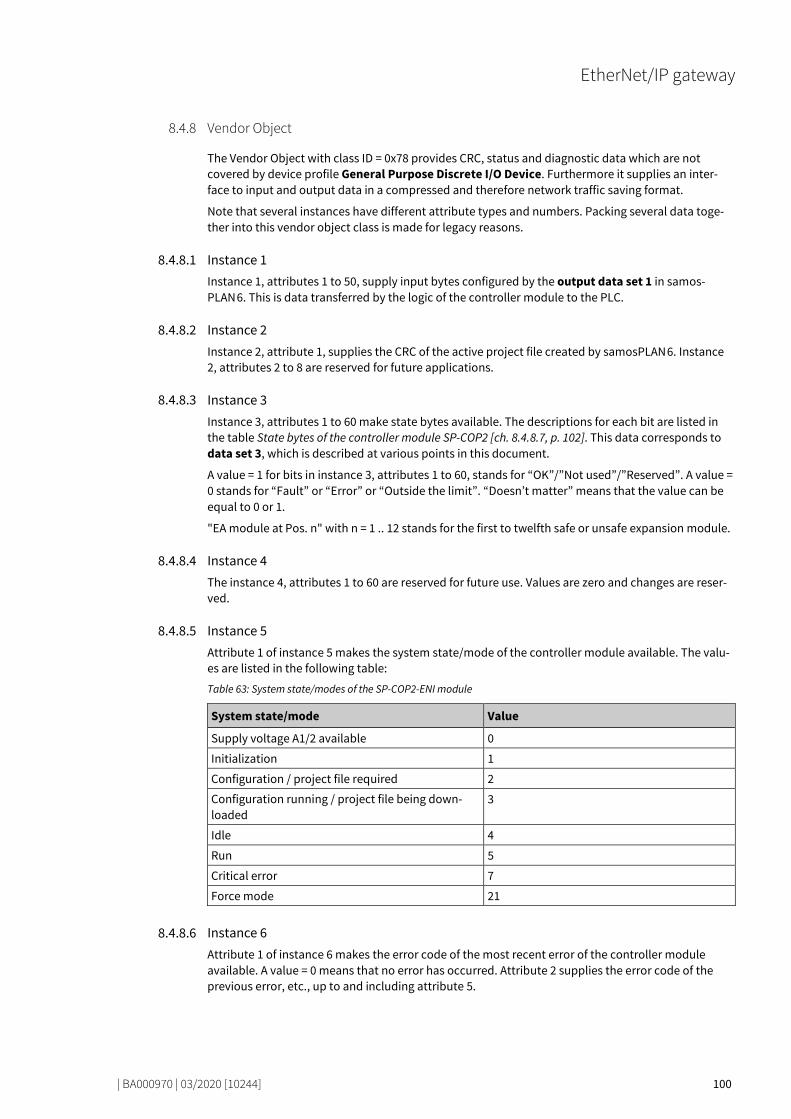
EtherNet/IP gateway
| BA000970 | 03/2020 [10244] 100
Vendor Object 80306315
The Vendor Object with class ID = 0x78 provides CRC, status and diagnostic data which are not covered by device profile General Purpose Discrete I/O Device. Furthermore it supplies an inter-face to input and output data in a compressed and therefore network traffic saving format.
Note that several instances have different attribute types and numbers. Packing several data toge-ther into this vendor object class is made for legacy reasons. 80315659
Instance 1 Instance 1, attributes 1 to 50, supply input bytes configured by the output data set 1 in samos-PLAN 6. This is data transferred by the logic of the controller module to the PLC. 80328203
Instance 2 Instance 2, attribute 1, supplies the CRC of the active project file created by samosPLAN 6. Instance 2, attributes 2 to 8 are reserved for future applications. 80338443
Instance 3 Instance 3, attributes 1 to 60 make state bytes available. The descriptions for each bit are listed in the table State bytes of the controller module SP-COP2 [ch. 8.4.8.7, p. 102]. This data corresponds to data set 3, which is described at various points in this document.
A value = 1 for bits in instance 3, attributes 1 to 60, stands for “OK”/”Not used”/”Reserved”. A value = 0 stands for “Fault” or “Error” or “Outside the limit”. “Doesn’t matter” means that the value can be equal to 0 or 1.
"EA module at Pos. n" with n = 1 .. 12 stands for the first to twelfth safe or unsafe expansion module. 80354827
Instance 4 The instance 4, attributes 1 to 60 are reserved for future use. Values are zero and changes are reser-ved. 80364171
Instance 5 Attribute 1 of instance 5 makes the system state/mode of the controller module available. The valu-es are listed in the following table:
Table 63: System state/modes of the SP-COP2-ENI module
System state/mode Value
Supply voltage A1/2 available 0
Initialization 1
Configuration / project file required 2
Configuration running / project file being down-loaded
3
Idle 4
Run 5
Critical error 7
Force mode 21
80378251
Instance 6 Attribute 1 of instance 6 makes the error code of the most recent error of the controller module available. A value = 0 means that no error has occurred. Attribute 2 supplies the error code of the previous error, etc., up to and including attribute 5. 80390027
8.4.8
8.4.8.1
8.4.8.2
8.4.8.3
8.4.8.4
8.4.8.5
8.4.8.6

EtherNet/IP gateway
| BA000970 | 03/2020 [10244] 101
Instance 7 Attributes 1 to 50 of instance 7 represent the input data blocks 1 to 5 in samosPLAN 6. They re-present the data transferred by the PLC to the logic of the controller module.
Attributes 1 to 50 of instance 7 possess the same data as assembly instance 37, byte 0 to 49.
NOTICE You can find an explanation of the technical terms used below here: Abbreviations and Definitions [ch. 1.5, p. 11]
Table 64: Overview of th vendor-specific object (Wieland Electric, 0x78), supported by the SP-COP2-ENI module
Class Instance Attribute Access Data type Description Data range
120 0 = Class 1 Read UINT Revision of the class 1
120 0 = Class 2 Read UINT Max. instance 4
120 0 = Class 3 Read UINT Number of instances 4
120 0 = Class 5 Read UINT[3] List of optional services 2, 0x4c, 0x4d
120 0 = Class 6 Read UINT Max. class attribute ID 7
120 0 = Class 7 Read UINT Max. instance attribute ID 60
120 1 n+1 Read USINT The input byte “n”, configured by the output data set 1 in samosPLAN 6, stands for the data transferred by the logic of the controller module to the PLC. n = 0 to 49.
0 to 255
120 2 1 Read UDINT Project file CRC (data set 2) 0 to 232-1
120 2 2 to 8 Read UDINT Reserved (data set 2) 0
120 3 n+1 Read BYTE State byte “n” of the controller module, for which n = 0 to 59
0 to 255
120 4 n+1 Read BYTE Additional byte “n” of the con-troller module, for which n = 0 to 59
0
120 5 1 Read USINT SP-COP2-ENI System mode (See [ch. 8.4.8.5, p. 100])
1, 2, 3, 4, 5, 7, 21
120 6 n Read UDINT Error code in the controller module, with n = 1 for the most recently occurred error, n = 2 for the previous error, etc., with n = 1 to 5
0 to 232-1
120 6 1 Write UDINT Clear error list in instance 6 0
120 7 n+1 Write, read
BYTE Output bit “n”, which is configu-red by the input data blocks 1 to 5 in samosPLAN 6, stands for the data transferred by the PLC to the logic of the controller module. n = 0 to 49.
0 to 255
8.4.8.7
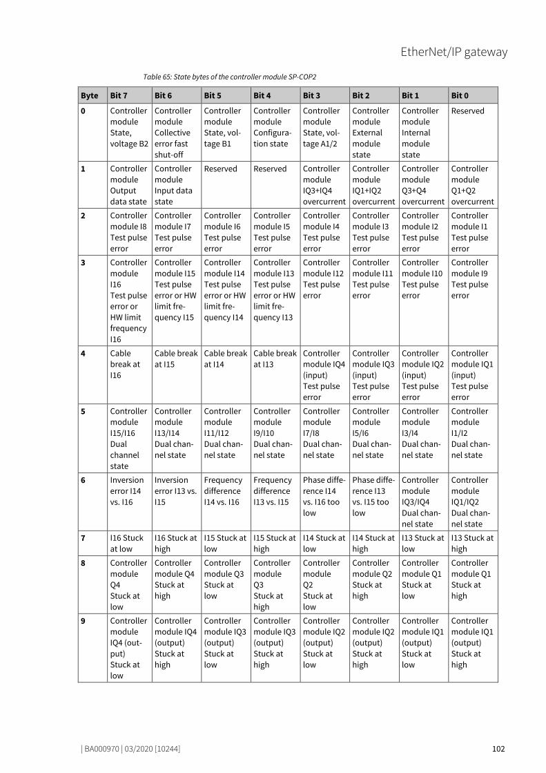
EtherNet/IP gateway
| BA000970 | 03/2020 [10244] 102
Table 65: State bytes of the controller module SP-COP2
Byte Bit 7 Bit 6 Bit 5 Bit 4 Bit 3 Bit 2 Bit 1 Bit 0
0 Controller module State, voltage B2
Controller module Collective error fast shut-off
Controller module State, vol-tage B1
Controller module Configura-tion state
Controller module State, vol-tage A1/2
Controller module External module state
Controller module Internal module state
Reserved
1 Controller module Output data state
Controller module Input data state
Reserved Reserved Controller module IQ3+IQ4 overcurrent
Controller module IQ1+IQ2 overcurrent
Controller module Q3+Q4 overcurrent
Controller module Q1+Q2 overcurrent
2 Controller module I8 Test pulse error
Controller module I7 Test pulse error
Controller module I6 Test pulse error
Controller module I5 Test pulse error
Controller module I4 Test pulse error
Controller module I3 Test pulse error
Controller module I2 Test pulse error
Controller module I1 Test pulse error
3 Controller module I16 Test pulse error or HW limit frequency I16
Controller module I15 Test pulse error or HW limit fre-quency I15
Controller module I14 Test pulse error or HW limit fre-quency I14
Controller module I13 Test pulse error or HW limit fre-quency I13
Controller module I12 Test pulse error
Controller module I11 Test pulse error
Controller module I10 Test pulse error
Controller module I9 Test pulse error
4 Cable break at I16
Cable break at I15
Cable break at I14
Cable break at I13
Controller module IQ4 (input) Test pulse error
Controller module IQ3 (input) Test pulse error
Controller module IQ2 (input) Test pulse error
Controller module IQ1 (input) Test pulse error
5 Controller module I15/I16 Dual channel state
Controller module I13/I14 Dual chan-nel state
Controller module I11/I12 Dual chan-nel state
Controller module I9/I10 Dual chan-nel state
Controller module I7/I8 Dual chan-nel state
Controller module I5/I6 Dual chan-nel state
Controller module I3/I4 Dual chan-nel state
Controller module I1/I2 Dual chan-nel state
6 Inversion error I14 vs. I16
Inversion error I13 vs. I15
Frequency difference I14 vs. I16
Frequency difference I13 vs. I15
Phase diffe-rence I14 vs. I16 too low
Phase diffe-rence I13 vs. I15 too low
Controller module IQ3/IQ4 Dual chan-nel state
Controller module IQ1/IQ2 Dual chan-nel state
7 I16 Stuck at low
I16 Stuck at high
I15 Stuck at low
I15 Stuck at high
I14 Stuck at low
I14 Stuck at high
I13 Stuck at low
I13 Stuck at high
8 Controller module Q4 Stuck at low
Controller module Q4 Stuck at high
Controller module Q3 Stuck at low
Controller module Q3 Stuck at high
Controller module Q2 Stuck at low
Controller module Q2 Stuck at high
Controller module Q1 Stuck at low
Controller module Q1 Stuck at high
9 Controller module IQ4 (out-put) Stuck at low
Controller module IQ4 (output) Stuck at high
Controller module IQ3 (output) Stuck at low
Controller module IQ3 (output) Stuck at high
Controller module IQ2 (output) Stuck at low
Controller module IQ2 (output) Stuck at high
Controller module IQ1 (output) Stuck at low
Controller module IQ1 (output) Stuck at high

EtherNet/IP gateway
| BA000970 | 03/2020 [10244] 103
Byte Bit 7 Bit 6 Bit 5 Bit 4 Bit 3 Bit 2 Bit 1 Bit 0
10 Reserved 1. Gateway module Output data state
1. Gateway module Input data state
1. Gateway module Configura-tion state
Doesn’t matter
Reserved 1. Gateway module Internal module state
Doesn’t matter
11 Reserved 2. Gateway module Output data state
2. Gateway module Input data state
2. Gateway module Configura-tion state
Doesn’t matter
Reserved 2. Gateway module Internal module state
Doesn’t matter
8 + 4⋅n Reserved IO module at pos. n Collective error fast shut-off
IO module at pos. n State, vol-tage A1/2 (power supply for Q1 to Q4)
IO module at pos. n Configura-tion state
Doesn’t matter
IO module at pos. n External module state
IO module at pos. n Internal module state
Doesn’t matter
9 + 4⋅n IO module at pos. n Output data state
IO module at pos. n Input data state
Reserved Reserved IO module at pos. n I7/I8 Dual chan-nel state
IO module at pos. n I5/I6 Dual chan-nel state
IO module at pos. n I3/I4 Dual chan-nel state
IO module at pos. n I2/I1 Dual chan-nel state
10 + 4⋅n
IO module at pos. n I8 test pulse error
IO module at pos. n I7 test pulse error
IO module at pos. n I6 test pulse error
IO module at pos. n I5 test pulse error
IO module at pos. n I4 test pulse error
IO module at pos. n I3 test pulse error
IO module at pos. n I2 test pulse error
IO module at pos. n I1 test pulse error
11 + 4⋅n
IO module at pos. n Q4 Stuck-at low
IO module at pos. n Q4 Stuck-at high
IO module at pos. n Q3 Stuck-at low
IO module at pos. n Q3 Stuck-at high
IO module at pos. n Q2 Stuck-at low
IO module at pos. n Q2 Stuck-at high
IO module at pos. n Q1 Stuck-at low
IO module at pos. n Q1 Stuck-at high
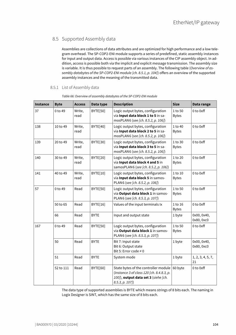
EtherNet/IP gateway
| BA000970 | 03/2020 [10244] 104
Supported Assembly data 80445195
Assemblies are collections of data attributes and are optimized for high performance and a low tele-gram overhead. The SP-COP2-ENI module supports a series of predefined, static assembly instances for input and output data. Access is possible via various instances of the CIP assembly object. In ad-dition, access is possible both via the implicit and explicit message transmission. The assembly size is variable. It is thus possible to request parts of an assembly. The following table (Overview of as-sembly databytes of the SP-COP2-ENI module [ch. 8.5.1, p. 104]) offers an overview of the supported assembly instances and the meaning of the transmitted data.
List of Assembly data 80460299
Table 66: Overview of assembly databytes of the SP-COP2-ENI module
Instance Byte Access Data type Description Size Data range
37 0 to 49 Write, read
BYTE[50] Logic output bytes, configuration via Input data block 1 to 5 in sa-mosPLAN 6 (see [ch. 8.5.2, p. 106])
1 to 50 Bytes
0 to 0xff
138 10 to 49 Write, read
BYTE[40] Logic output bytes, configuration via Input data block 2 to 5 in sa-mosPLAN 6 (see [ch. 8.5.2, p. 106])
1 to 40 Bytes
0 to 0xff
139 20 to 49 Write, read
BYTE[30] Logic output bytes, configuration via Input data block 3 to 5 in sa-mosPLAN 6 (see [ch. 8.5.2, p. 106])
1 to 30 Bytes
0 to 0xff
140 30 to 49 Write, read
BYTE[20] Logic output bytes, configuration via Input data block 4 and 5 in samosPLAN 6 (see [ch. 8.5.2, p. 106])
1 to 20 Bytes
0 to 0xff
141 40 to 49 Write, read
BYTE[10] Logic output bytes, configuration via Input data block 5 in samos-PLAN 6 (see [ch. 8.5.2, p. 106])
1 to 10 Bytes
0 to 0xff
57 0 to 49 Read BYTE[50] Logic output bytes, configuration via Output data block 1 in samos-PLAN 6 (see [ch. 8.5.3, p. 107])
1 to 50 Bytes
0 to 0xff
50 to 65 Read BYTE[16] Values of the input terminals Ix 1 to 16 Bytes
0 to 0xff
66 Read BYTE Input and output state 1 byte 0x00, 0x40, 0x80, 0xc0
167 0 to 49 Read BYTE[50] Logic output bytes, configuration via Output data block 1 in samos-PLAN 6 (see [ch. 8.5.3, p. 107])
1 to 50 Bytes
0 to 0xff
50 Read BYTE Bit 7: Input state Bit 6: Output state Bit 5: Error code ≠ 0
1 byte 0x00, 0x40, 0x80, 0xc0
51 Read BYTE System mode 1 byte 1, 2, 3, 4, 5, 7, 21
52 to 111 Read BYTE[60] State bytes of the controller module (Instance 3 of class 120 [ch. 8.4.8.3, p. 100]), output data set 3 (siehe [ch. 8.5.3, p. 107])
60 byte 0 to 0xff
The data type of supported assemblies is BYTE which means strings of 8 bits each. The naming in Logix Designer is SINT, which has the same size of 8 bits each.
8.5
8.5.1
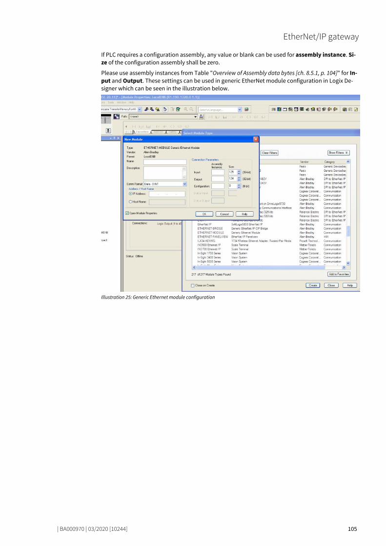
EtherNet/IP gateway
| BA000970 | 03/2020 [10244] 105
If PLC requires a configuration assembly, any value or blank can be used for assembly instance. Si-ze of the configuration assembly shall be zero.
Please use assembly instances from Table "Overview of Assembly data bytes [ch. 8.5.1, p. 104]" for In-put and Output. These settings can be used in generic EtherNet module configuration in Logix De-signer which can be seen in the illustration below.
Illustration 25: Generic Ethernet module configuration

EtherNet/IP gateway
| BA000970 | 03/2020 [10244] 106
Assembly Instances for Logic Output Bytes 80510219
80522635
Assembly Instance 37 = 0x25 Assembly instance 37 belongs to the device profile discrete universal I/O device. It contains output data (O→T) with a scope of up to 50 bytes.
Assembly instance 37 corresponds to input data block 1 to 5 of the logic data of the SP-COP2-ENI module with a total scope of 50 bytes. 80534027
Assembly Instances 138 = 0x8a to 141 = 0x8d Assembly instances 138 to 141 are provided to make more than one output data connection availab-le. In Class 1 connections, output data from the PLC to the controller module can only be sent using “Exclusive Owner” rights. If, for example, a PLC “possesses” the assembly instance 138, then it “pos-sesses” the output bytes 10 to 49. By contrast, output bytes 0 to 9 are freely available and can be used by another PLC (O→T).
In a further example, the first PLC “possesses” 10 output bytes of the assembly instance 37, whilst the second PLC “possesses” 10 output bytes of assembly instance 138 and the third assembly in-stance 139 with 30 output bytes. Here, three PLCs possess “Exclusive Owner” connections with out-put data. In total, up to five PLCs can share the output data range, each with 10 bytes.
Assembly instance 138 comprises data with a scope of up to 40 bytes, assembly instance 139 com-prises data with a scope of up to 30 bytes, assembly instance 140 comprises data with a scope of up to 20 bytes and assembly instance 141 comprises data with a scope of up to 10 bytes.
The first byte of assembly instance 138 is the eleventh byte of the logic data of the SP-COP2-ENI mo-dule. In samosPLAN 6, it has the designation input data block 2. The first byte of assembly instance 139 is 21. Byte of the logic data of module SP-COP2-ENI. In samosPLAN 6, it has the designation in-put data block 3. The first byte of assembly instance 140 is 31. Byte of the logic data of module SP-COP2-ENI. In samosPLAN 6, it has the designation input data block 4. The first byte of assembly in-stance 141 is 41. Byte of the logic data of module SP-COP2-ENI. In samosPLAN 6, it has the designati-on input data block 5.
Write requests are refused if the assembly is already used by an active I/O connection.
8.5.2
8.5.2.1
8.5.2.2
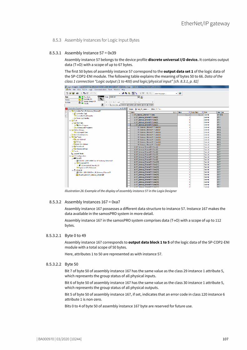
EtherNet/IP gateway
| BA000970 | 03/2020 [10244] 107
Assembly Instances for Logic Input Bytes 80545803
80555787
Assembly Instance 57 = 0x39 Assembly instance 57 belongs to the device profile discrete universal I/O device. It contains output data (T→O) with a scope of up to 67 bytes.
The first 50 bytes of assembly instance 57 correspond to the output data set 1 of the logic data of the SP-COP2-ENI module. The following table explains the meaning of bytes 50 to 66. Data of the class 1 connection “Logic output (1 to 400) and logic/physical input” [ch. 8.3.1, p. 82]
Illustration 26: Example of the display of assembly instance 57 in the Logix Designer
80571019
Assembly Instances 167 = 0xa7 Assembly instance 167 possesses a different data structure to instance 57. Instance 167 makes the data available in the samosPRO system in more detail.
Assembly instance 167 in the samosPRO system comprises data (T→O) with a scope of up to 112 bytes. 80584715
Byte 0 to 49 Assembly instance 167 corresponds to output data block 1 to 5 of the logic data of the SP-COP2-ENI module with a total scope of 50 bytes.
Here, attributes 1 to 50 are represented as with instance 57. 80595723
Byte 50 Bit 7 of byte 50 of assembly instance 167 has the same value as the class 29 instance 1 attribute 5, which represents the group status of all physical inputs.
Bit 6 of byte 50 of assembly instance 167 has the same value as the class 30 instance 1 attribute 5, which represents the group status of all physical outputs.
Bit 5 of byte 50 of assembly instance 167, if set, indicates that an error code in class 120 instance 6 attribute 1 is non-zero.
Bits 0 to 4 of byte 50 of assembly instance 167 byte are reserved for future use. 80605067
8.5.3
8.5.3.1
8.5.3.2
8.5.3.2.1
8.5.3.2.2

EtherNet/IP gateway
| BA000970 | 03/2020 [10244] 108
Byte 51 Byte 51 of assembly instance 167 supplies the system mode of the controller modules. It shows the same value as attribute 1 of instance 5 in class 120. 80616075
Byte 52 to 111 Bytes 52 to 111 of assembly instance 167 make the corresponding state bytes of the controller mode available. They show the same value as attributes 1 to 60 of instance 3 in class 120.
8.5.3.2.3
8.5.3.2.4

EtherNet/IP gateway
| BA000970 | 03/2020 [10244] 109
Accessing to CIP objects 80632203
Explicit Messaging 80642443
Explicit message transmission uses the TCP/IP protocol as well as an EtherNet/IP-specific encapsu-lation layer. Explicit message transmission can be connection-free (UCMM) and connected, e.g. ses-sion-based. The latter is termed Class 3 Messaging. Both UCMM and Class 3 use an EPATH to address the required data. An EPATH is made up of the service, class, instance and attribute ID.
With explicit message transmission, each attribute of the following objects can be accessed: • Identity class (0x01) [ch. 8.4.1, p. 88] • Assembly class (0x04) [ch. 8.4.2, p. 89] • Discrete input point object (0x08) [ch. 8.4.3, p. 90] • Discrete output point object [ch. 8.4.4, p. 92] • Discrete einput group object (0x1D) [ch. 8.4.5, p. 92] • Discrete output group object (0x1D) [ch. 8.4.6, p. 93] • Vendor-specific object (0x78) [ch. 8.4.8.7, p. 101]
Each request must possess a valid EPATH referring to the required object/attribute. The appropriate attribute can be read using the GetAttributeSingle service, if it is labeled as Read in these tables. The appropriate attribute can be written using the SetAttributeSingle service, if it is labeled as Write in these tables.
Implicit Messaging 80662667
Implicit message transmission uses EtherNet/IP, the UDP/IP protocol as well as an EtherNet/IP-specific encapsulation layer. Implicit message transmission is also termed Transport Class 1. The PLC can set up a Class 1 connection with the SP-COP2-ENI module, by placing the service request Forward_Open with it. This configures connection information for the exchange of input/output da-ta, e.g. the RPI unicast or multicast connections, amongst other things. Class 1 connections only support assemblies for the exchange of input/output data or “wild cards” to signal data-free heart-beat connections. Configuration assemblies are accepted as part of the Forward_Open-Service, with the exception of TCP/IP objects (Class 0xF5), although are not processed by the SP-COP2-ENI modu-le.
As the configuration details of the connection are only sent once in the Forward_Open-Frame, im-plicit message transmission is aligned to performance and has a lower telegram overhead than ex-plicit message transmission. Assembly instances possess predefined attributes in a specific order. Nonetheless, the sender, i.e. the PLC; specifies the data size in Forward_Open during the setup of the Class 1 connection. This means that only data byte from the beginning of the instance up to the specified size are exchanged.
The SP-COP2-ENI module supports seven static assembly instances. These are listed in the table Overview of the assembly class (0x04) supported by the SP-COP2-ENI module [ch. 8.4.2, p. 89]. All data members of the instance has fixed coding. Dynamic assembly instances are not currently supported by the SP-COP2-ENI module.
An I/O assembly contains either input or output data, but not both at the same time. The following figure shows the data flow when multiple assembly instances are used. Predefined assemblies are interconnected by blue lines, vendor-specific assemblies by black lines. The controller module is shown as a hatched rectangle.
8.6
8.6.1
8.6.2

EtherNet/IP gateway
| BA000970 | 03/2020 [10244] 110
Illustration 27: Data flow when using assembly instances of the SP-COP2-ENI module
Symbolic Addressing 80679819
In addition to the addressing of assembly instances, symbolic addressing by name is also possible by selecting connections.
In samosPLAN 6, tag names can be changed in the Gateway configuration tab.
Illustration 28: Configuration of symbolic names for assemblies in samosPLAN 6
NOTICE The functions of the UCMM Message Client (unconnected), which can also be configured in samos-PLAN 6, are not available in the module version D-01.01.
8.6.3

EtherNet/IP gateway
| BA000970 | 03/2020 [10244] 111
Adjust Performance 80697611
A configuration of the number of process data bytes exactly matching the application helps to re-duce the volume of periodically exchanged data bytes.
The PLC specifies the number of output bytes in the form of specific Forward_Open Service data as Connection Size for O→T. The PLC should set the Fixed/Variable bit to 1, meaning variable.
The PLC also specifies the number of input bytes. The controller module cyclically transfers data in the scope of the connection size for T→O through RPI in the value specified in Forward_Service. If the fixed/variable bit is set by the PLC, meaning variable, then not all the assembly bytes must be transmitted.
Connection with more than one PLC 80711307
The EtherNet/IP function of the SP-COP2-ENI module allows access by more than one PLC. Up to five encapsulation sessions with input and output data can be set up simultaneously.
If only reading of the process data of the SP-COP2-ENI module is required, “Input only” or “Listen only” connections can also be used. Note that a “Listen only” connection is closed automatically by the SP-COP2-ENI module when the owner, who has set up the “Exclusive” or “Input Only” connec-tion, terminates the connection.
If process data from multiple PLCs are to be transmitted to the SP-COP2-ENI module, the other PLCs can access the assembly instances 138 to 141 for Class 1 connections. Class 3 connections can be set up in parallel, provided that there is no conflict with regard to the owner. Please see the following for more information: List of Assembly data [ch. 8.5.1, p. 104]
8.7
8.8

EtherNet/IP gateway
| BA000970 | 03/2020 [10244] 112
Diagnostics and troubleshooting 80725003
Notifications via network 80735243
80745483
Explicit Message Connection Device Status is available by reading Class 1, instance 1, attribute 5. Vendor specific interface for alarms and diagnostic for Explicit Message Connections is defined as follows:
Presence of process alarm can be detected by reading class 29, instance 1, attribute 5 and class 30, instance 1, attribute 5. The module mode (Run or another state) has to be checked, because the alarm bit is set to 0 = OK every time the module is not in Run mode.
The module mode can be detected by reading class 120 Instance 5 Attribute 1.
The presence of module diagnostic events can be detected by reading class 120 Instance 6 Attribute 1.
Detailed reasons for process alarms and system diagnostic events can be found out by reading all 60 attributes of Class 120 Instance 3 which contains the dedicated system status bytes. 80754827
Implicit Message Connection If assembly instance 57 is used, Bit 6 and 7 of Byte 66 signal a process alarm when set.
If assembly instance 167 is used, Bit 6 and 7 of Byte 66 signal a process alarm when set. Bit 5 signals diagnostic events or process alarms when set.
Event details can be queried by Explicit Message requests as described here: Explicit Messaging [ch. 8.6.1, p. 109]
LED States 80764171
80774411
MS (Module Status) The SP-COP2-ENI module possesses a two-color (red/green) LED with the designation MS. This is the Module Status Indicator.
The Module Status Indicator is dark, if no power supply is connected. It flashes green if the device has not been configured. It turns green if the device is running correctly. It flashes green/red if the device is performing a switch-on test.
The Module Status Indicator flashes red if EtherNet/IP is activated and the device has detected a se-rious, eliminable error. A faulty project file or one which does not match the hardware is classified as a serious, eliminable error. The display turns red if EtherNet/IP is activated and the device has detec-ted a serious, non-eliminable error and there is a Critical Fault.
Table 67: MS-LED state (Selection)
Project file System mode Ext. Error MS-LED state
Doesn’t matter Switch on Doesn’t matter Green -> Red
Deleted Init Doesn’t matter Flashing green
Invalid Init Doesn’t matter Flashing red
Valid Idle mode Doesn’t matter Flashing green
Valid Run No Turns green
Valid Run Yes Turns green/red or flashes red
Valid Critical error Doesn’t matter Turns red
80788875
8.9
8.9.1
8.9.1.1
8.9.1.2
8.9.2
8.9.2.1

EtherNet/IP gateway
| BA000970 | 03/2020 [10244] 113
NET (Network Status) The SP-COP2-ENI module possesses a two-color (red/green) LED with the designation NET. This is the Network Status Indicator.
Table 68: Meaning of the NET LED (used as EtherNet/IP gateway)
NET LED Meaning / reason
LED off • Power supply not connected. or
• Power supply connected but IP address not configured.
Green (1 Hz)
EtherNet/IP has been activated and an IP address has been configured but there is no CIP connection and an “Exclusive Owner” connection has not yet shown a time-out.
Green An IP address has been configured, there is at least one CIP connection (of any transport class) and an “Exclusive Owner” connection has not yet shown a time-out.
/ Red/green
During power-on test
Red EtherNet/IP has been activated, an IP address has been configured and an “Exclusi-ve Owner” connection, for which the device is the target device, has shown a time-out.
The Network Status Indicator is dark if no power supply is connected or a power supply is connected but no IP address is configured (interface configuration attribute of the TCP/IP interface object). It flashes green if EtherNet/IP is activated and an IP address has been configured but no CIP connec-tion is available and an “Exclusive Owner” connection has not yet shown a time-out. It turns green if an IP address has been configured, there is at least one CIP connection (of any transport class) and an “Exclusive Owner” connection has not yet shown a time-out. It flashes green/red if the device is performing a switch-on test.
The Network Status Indicator flashes red if EtherNet/IP is activated, an IP address has been configu-red and an “Exclusive Owner” connection, for which the device is the target device, has shown a ti-me-out. The Network Status Indicator only turns green again when all the expired “Exclusive Owner” connections have been restored. The Network Status Indicator switches from flashing red to being lit in green if all the connections of the previously expired O->T connection points have been resto-red. Time-outs in other connections than the "Exclusive Owner” connections do not result in the in-dicator flashing red. The “flashing red” state only applies to connections with the target device. PLCs and CIP routers do not instigate a transition to this state if a created or routed connection shows a time-out.
Table 69: Troubleshooting on the SP-COP2-ENI module (use as EtherNet/IP gateway)
Error Possible cause Possible remedy
Key: LED off / LED flashes / LED lights up
The SP-COP2-ENI module does not provide any data.
• The SP-COP2-ENI has been configured for data trans-mission to the PLC, but no Ethernet communication has been established or the communication is faulty.
• Duplicate IP address detec-ted. Another network de-vice has the same IP address.
• Incorrectly formatted PRO-FINET device name
• PROFINET IO must be activated in the project file. At least one Ethernet link must be establis-hed. Check the Ethernet wiring, check the Ethernet settings in the PLC and in samosPLAN 6.
• Correct the IP address and switch the system off and on again.
• Compare the device name between the PROFINET master and the SP-COP2-ENI module.
LED PWR/EC Green
LED LINK Green
LED /ACT Yellow
MS LED Green
8.9.2.2

EtherNet/IP gateway
| BA000970 | 03/2020 [10244] 114
Error Possible cause Possible remedy
The SP-COP2-ENI module does not provide any data.
• Configuration required. • The configuration has not
yet been fully transmitted. • The module version does
not support any PROFINET IO.
• Configure the SP-COP2-ENI module with a project file in which PROFINET IO is activated and transfer the configuration to the SP-COP2-ENI module.
• Use an SP-COP2-ENI device starting with module version B-xx.
LED PWR/EC Green
LED LINK Green
LED /ACT Yellow
MS LED /
Red/green
The SP-COP2-ENI module does not provide any data.
• The samosPRO system is in the stop state.
• Start the controller module (switch to Run mode).
LED PWR Green
LED LINK Green
LED /ACT Yellow
MS LED
Green (1 Hz)
The SP-COP2-ENI module does not provide any data.
• The IP address for the SP-COP2-ENI module is assig-ned by a DHCP server. Following a restart of the SP-COP2-ENI module or the DHCP server, another address was allocated to the SP-COP2-ENI module, which is unknown to the PLC.
• Either assign the SP-COP2-ENI module a permanent IP address or reserve a perma-nent IP address for the SP-COP2-ENI module in the DHCP server (manual assignment u-sing the MAC address of the SP-COP2-ENI module).
LED PWR/EC Green
LED LINK Green
LED /ACT Yellow
MS LED Green
The SP-COP2-ENI / the samosPRO system is in the “Critical error” state.
• The SP-COP2-ENI module is not properly connected to the samosPRO modules.
• The module connection plug is dirty or damaged.
• Another samosPRO module has an internal critical er-ror.
• Insert the I/O module correctly. Clean the connection plug and socket.
• Switch on the power supply again.
• Check the other samosPRO modules.
80809739
LINK The SP-COP2-ENI module possesses a green LED with the designation LINK. If there is no Ethernet connection, it stays dark. If there is a connection, it switches on. 80821131
ACT (Activity Status) The SP-COP2-ENI module possesses a green LED with the designation ACT. If no port activity can be detected, it stays dark. If port activity is detected, it switches on.
8.9.2.3
8.9.2.4

EtherNet/IP gateway
| BA000970 | 03/2020 [10244] 115
Diagnostic functions in the configuration software 80832139
Additional diagnostic functions are available on the SD card using a log file with the name histo-ry.csv. In addition, the last entries are available in samosPLAN 6 in the Diagnostics view. The ti-mestamp in the Local time column provides information about how long the device has been swit-ched on in total.
Synchronize time With the safety controller connected you can synchronize the time on the safety controller with the time on the connected diagnostics computer. Even if you disconnect the connection to the control-ler, the Diagnostics view remains active, as long as the associated samosPLAN 6 project is open.
NOTICE Instructions in software manual You can find step-by-step instructions on how to synchronize the time here: Software manual, chapter "Synchronize time for diagnostic purposes"
8.9.3

EtherNet/IP gateway
| BA000970 | 03/2020 [10244] 116
State bits 80861963
The EtherNet/IP gateway SP-EN-IP sets state bits, which are available in the logic editor of samos-PLAN 6 for processing.
Table 70: Meaning of the state bits SP-EN-IP[0] in the logic editor
Name of the state bits Set to 1, if ... Reset to 0 ...
Output state ... a GetAttribute command was processed successfully, or ... data of transport class 1 were sent to a PLC without errors.
... if a connection of transport class 1 (implicit connection) was terminated and no further connection exists.
Input state ... a SetAttribute command was processed successfully, or ... data of transport class 1 recei-ved without error (consumed), whereby heartbeat data of connection point 198 from the PLC does not count
... a connection of transport class 1 (implicit connection) was terminated for one of the connection points 57, 138, 139, 140 or 141 and no further connection exists to these connection points.
Internal state ... the EtherNet/IP function of the module is ready for communica-tion.
... the EtherNet/IP function of the module is not ready for communication.
8.10
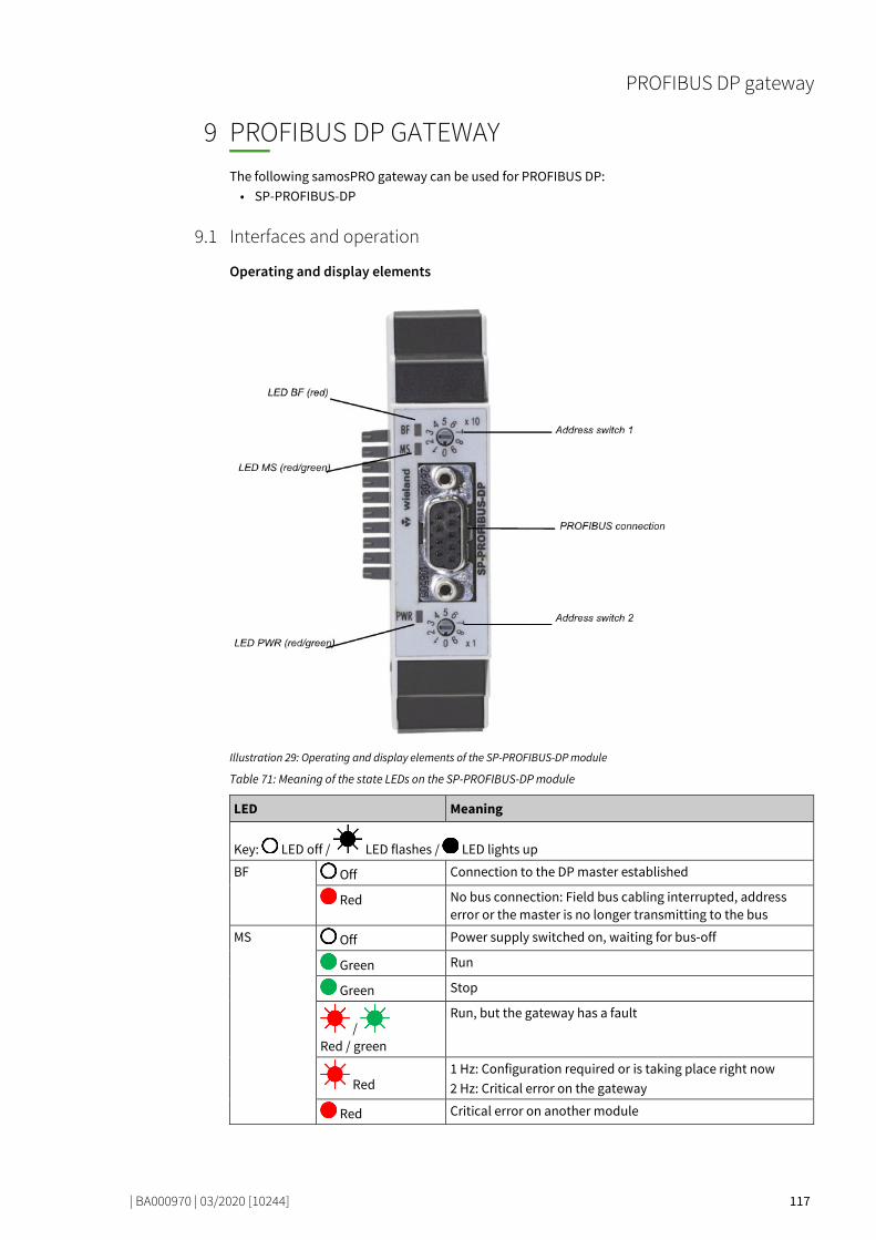
PROFIBUS DP gateway
| BA000970 | 03/2020 [10244] 117
PROFIBUS DP GATEWAY
78225803
The following samosPRO gateway can be used for PROFIBUS DP: • SP-PROFIBUS-DP
Interfaces and operation 78236299
Operating and display elements
Illustration 29: Operating and display elements of the SP-PROFIBUS-DP module
Table 71: Meaning of the state LEDs on the SP-PROFIBUS-DP module
LED Meaning
Key: LED off / LED flashes / LED lights up
BF
Off Connection to the DP master established
Red No bus connection: Field bus cabling interrupted, address error or the master is no longer transmitting to the bus
MS
Off Power supply switched on, waiting for bus-off
Green Run
Green Stop
/ Red / green
Run, but the gateway has a fault
Red 1 Hz: Configuration required or is taking place right now 2 Hz: Critical error on the gateway
Red Critical error on another module
9
9.1
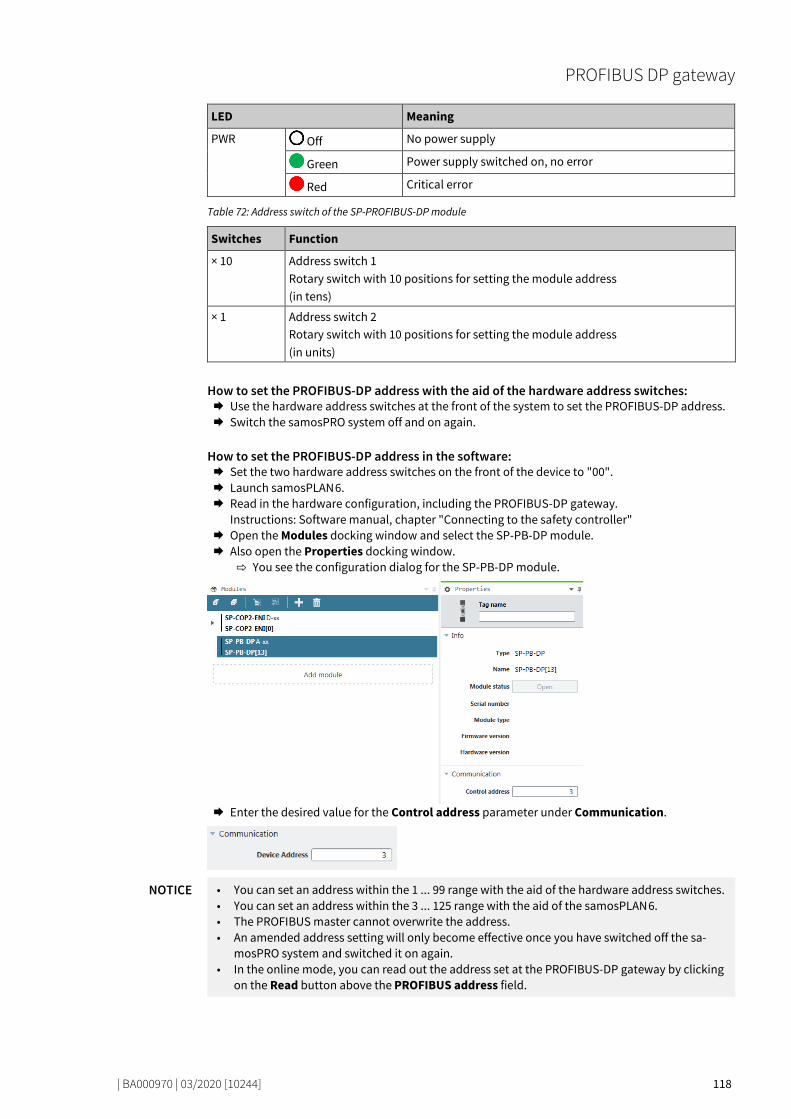
PROFIBUS DP gateway
| BA000970 | 03/2020 [10244] 118
LED Meaning
PWR
Off No power supply
Green Power supply switched on, no error
Red Critical error
Table 72: Address switch of the SP-PROFIBUS-DP module
Switches Function
× 10 Address switch 1 Rotary switch with 10 positions for setting the module address (in tens)
× 1 Address switch 2 Rotary switch with 10 positions for setting the module address (in units)
How to set the PROFIBUS-DP address with the aid of the hardware address switches: Use the hardware address switches at the front of the system to set the PROFIBUS-DP address. Switch the samosPRO system off and on again.
How to set the PROFIBUS-DP address in the software: Set the two hardware address switches on the front of the device to "00". Launch samosPLAN 6. Read in the hardware configuration, including the PROFIBUS-DP gateway.
Instructions: Software manual, chapter "Connecting to the safety controller" Open the Modules docking window and select the SP-PB-DP module. Also open the Properties docking window.
You see the configuration dialog for the SP-PB-DP module.
Enter the desired value for the Control address parameter under Communication.
NOTICE • You can set an address within the 1 ... 99 range with the aid of the hardware address switches. • You can set an address within the 3 ... 125 range with the aid of the samosPLAN 6. • The PROFIBUS master cannot overwrite the address. • An amended address setting will only become effective once you have switched off the sa-
mosPRO system and switched it on again. • In the online mode, you can read out the address set at the PROFIBUS-DP gateway by clicking
on the Read button above the PROFIBUS address field.

PROFIBUS DP gateway
| BA000970 | 03/2020 [10244] 119
Pin assignment Connection to the PROFIBUS-DP field bus is via a 9-pin D-sub socket.
Illustration 30: Pin configuration of D-sub socket and plug for the SP-PROFIBUS-DP module
Table 73: Reference for pin configuration
Pin Description
1 NC
2 NC
3 RxD/TxD-P
4 CNTR-P
5 GND-EXT
6 +5V-EXT
7 NC
8 RxD/TxD-N
9 CNTR-N (GND-EXT)
SHLD Shielding
Bus cable The bus topology for PROFIBUS DP is a linear structure consisting of a shielded and twisted 2-lead cable with active bus termination at both ends. The potential bus lengths range from 100 m at 12 kbit/s to 1200 m at 94 kbit/s.
Illustration 31: Bus cable of the SP-PROFIBUS-DP module
Table 74: Reference for pin configuration
Position Description
1 PROFIBUS user gray
2 Shielded bus cable
3 PROFIBUS termination yellow (with integrated terminal resistances)

PROFIBUS DP gateway
| BA000970 | 03/2020 [10244] 120
Line parameters The bus cable characteristics have been defined in EN 50170 as cable type A.
Table 75: Line parameters of the SP-PROFIBUS-DP module
Characteristic Value
Wave resistance 135-165 Ω (at a frequency of 3-20 MHz)
Capacity per length unit < 30 pF/m
Loop resistance ≤ 110 Ω/km
Lead diameter > 0.64 mm
Wire cross-section > 0.34 mm2
These cable parameters provide the following maximum physical dimensions for a bus section:
Table 76: Maximum line lengths of the SP-PROFIBUS-DP module
Baud rate (kbit/s) Maximum cable length (m)
9.6 1200
19.2 1200
93.75 1200
187.5 1000
500 400
1500 200
12000 100
Data transmission rate The data transmission rate is automatically set. The maximum baud rate is 12 Mbit/s.

PROFIBUS DP gateway
| BA000970 | 03/2020 [10244] 121
Projecting 78284043
GSD file Under normal circumstances, the SP-PROFIBUS-DP module is operated on a DP master that reads the device characteristics from the GSD file.
You will find the GSDML file and the equipment symbol for integration in a PLC of the product websi-te of the SP-PROFIBUS-DP on the Internet (https://eshop.wieland-electric.com/). Process data transmitted by the SP-PROFIBUS-DP module The GSD file of the SP-PROFIBUS-DP module provides input and output data blocks (virtual I/O de-vice modules), which contain the process data. These 5 blocks must be projected in a natural se-quence (1, 2, 3, 4, 5) in a DP configurator. No other sequence is possible.
Illustration 32: Example for a PROFIBUS-DP configuration in the Siemens SIMATIC manager
NOTICE • Depending on the PLC used, further modules may be shown (e.g. "Universal module"). These modules are not required and should be ignored.
• Data blocks 1–4 each contain 12 bytes, while data block 5 contains 2 bytes.
The content of the data blocks can be freely selected, but has been preconfigured as follows in the samosPLAN 6:
9.2

PROFIBUS DP gateway
| BA000970 | 03/2020 [10244] 122
Table 77: Predefined content of input data block 1–5 of the SP-PROFIBUS-DP module
Data block 1 Data block 2 Data block 3 Data block 4 Data block 5
Output data block Output data block Output data block Output data block Output data block
Byte 0 Input values for Module 0 (I1..I8)
Input values for Module 1
Output values for Module 1
Not allocated Not allocated
Byte 1 Input values for Module 0 (I9..I16)
Input values for Module 2
Output values for Module 2
Not allocated Not allocated
Byte 2 Input values for Module 0 (IQ1..IQ4)
Input values for Module 3
Output values for Module 3
Not allocated Not available
Byte 3 Output values for Module 0 (Q1..Q4,IQ1-IQ4)
Input values for Module 4
Output values for Module 4
Not allocated
Byte 4 Direct data (Off) 0
Input values for Module 5
Output values for Module 5
Not allocated
Byte 5 Direct data (Off) 1
Input values for Module 6
Output values for Module 6
Not allocated
Byte 6 Direct data (Off) 2
Input values for Module 7
Output values for Module 7
Not allocated
Byte 7 Direct data (Off) 3
Input values for Module 8
Output values for Module 8
Not allocated
Byte 8 Direct data (Off) 4
Input values for Module 9
Output values for Module 9
Not allocated
Byte 9 Direct data (Off) 5
Input values for Module 10
Output values for Module 10
Not allocated
Byte 10 Direct data (Off) 6
Input values for Module 11
Output values for Module 11
Not allocated
Byte 11 Direct data (Off) 7
Input values for Module 12
Output values for Module 12
Not allocated
Length 12 bytes 12 bytes 12 bytes 12 bytes 2 bytes
Start address
1 13 25 37 49
Detailed information about the content of the process diagram may be found here: Data transferred to the network (network input data sets [ch. 3.2, p. 20]).
Delete any bytes not required You can delete bytes pre-allocated by samosPLAN 6 that you do not require by clicking on them with the mouse. Launch samosPLAN 6. Read in the hardware configuration, including the PROFIBUS-DP gateway.
Instructions: Software manual, chapter "Connecting to the safety controller" Switch to the Gateway view. Click on the byte you do not need and wish to delete.
Click on the Delete icon in the command bar.
You will find further information about how to configure the process diagram here: • Configuration of gateways with samosPLAN 6 [ch. 5, p. 40] • Software manual
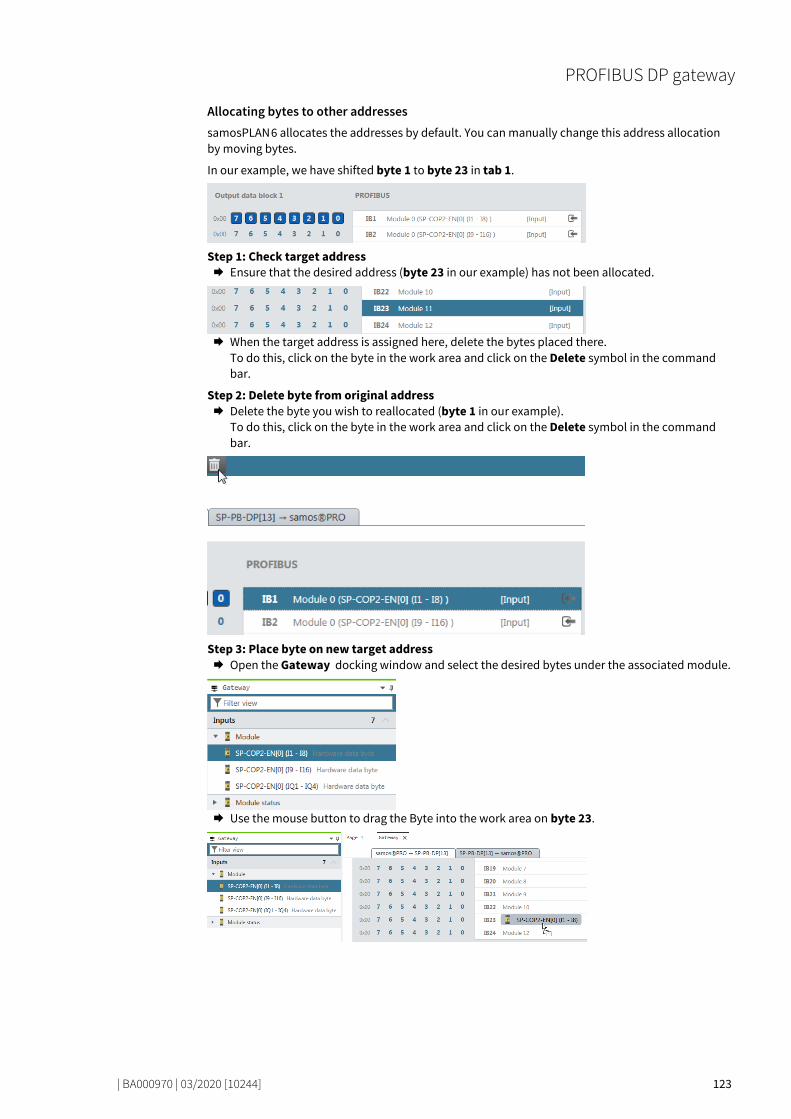
PROFIBUS DP gateway
| BA000970 | 03/2020 [10244] 123
Allocating bytes to other addresses samosPLAN 6 allocates the addresses by default. You can manually change this address allocation by moving bytes.
In our example, we have shifted byte 1 to byte 23 in tab 1.
Step 1: Check target address Ensure that the desired address (byte 23 in our example) has not been allocated.
When the target address is assigned here, delete the bytes placed there.
To do this, click on the byte in the work area and click on the Delete symbol in the command bar.
Step 2: Delete byte from original address Delete the byte you wish to reallocated (byte 1 in our example).
To do this, click on the byte in the work area and click on the Delete symbol in the command bar.
Step 3: Place byte on new target address Open the Gateway docking window and select the desired bytes under the associated module.
Use the mouse button to drag the Byte into the work area on byte 23.

PROFIBUS DP gateway
| BA000970 | 03/2020 [10244] 124
PROFIBUS configuration of the gateway - how the data are transferred 78346635
The following steps are required to configure the communication between the PLC and the gateway.
NOTICE This documentation does not address the installation of the PROFIBUS-DP network or the other components of the automation system project in the network configuration tool. It is assumed that the PROFIBUS project in the configuration program, e.g. the SIEMENS SIMATIC Manager, has al-ready been set up. The examples presented are based on configurations created with the help of the SIEMENS SIMATIC Manager.
Step 1: Install the device master file (GSD) Before the SP-PROFIBUS-DP can be used for the first time as part of the network configuration tool, e.g. the SIEMENS SIMATIC Manager, the device master file (GSD) of the gateway must first be instal-led in the hardware catalog of the tool. Download the GSD file and the equipment symbol from the product site of the SP-PROFIBUS-DP
module (https://eshop.wieland-electric.com/). Follow the instructions for the installation of GSD files in the online help section or in the user
manual for the PROFINET network configuration tool.
If you are using SIEMENS SIMATIC Manager (HW Config), the gateway will subsequently appear in the hardware catalog under >>PROFIBUS DP > Other field equipment > Gateway > Wieland > sa-mosPRO COMPACT.
9.3

PROFIBUS DP gateway
| BA000970 | 03/2020 [10244] 125
Step 2: Add the gateway to the project To make the system of the samosPRO system available in the process diagram of the PLC, the gate-way must first be added to the hardware configuration. The procedure to be used depends on the hardware configuration software of the PLC used. Please also read the documentation for the cor-responding software in this regard.
The example below shows how the gateway is added to a SIEMENS SIMATIC manager project.
In the SIEMENS SIMATIC hardware manager, you will find the gateway in the hardware catalog under >>PROFIBUS DP > Other field equipment > Gateway > Wieland > samosPRO COMPACT. Use the drag&drop function to pull the equipment into the PROFIBUS network. Example:
Illustration 33: PROFIBUS-DP gateway in the PROFIBUS HW Config
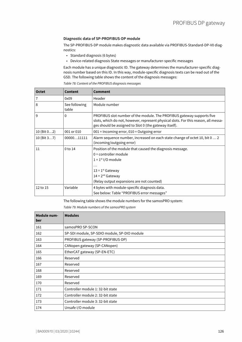
PROFIBUS DP gateway
| BA000970 | 03/2020 [10244] 126
Diagnostic data of SP-PROFIBUS-DP module The SP-PROFIBUS-DP module makes diagnostic data available via PROFIBUS-Standard-DP-V0 diag-nostics: • Standard diagnosis (6 bytes) • Device-related diagnosis State messages or manufacturer-specific messages
Each module has a unique diagnostic ID. The gateway determines the manufacturer-specific diag-nosis number based on this ID. In this way, module-specific diagnosis texts can be read out of the GSD. The following table shows the content of the diagnosis messages:
Table 78: Content of the PROFIBUS diagnosis messages
Octet Content Comment
7 0x09 Header
8 See following table
Module number
9 0 PROFIBUS slot number of the module. The PROFIBUS gateway supports five slots, which do not, however, represent physical slots. For this reason, all messa-ges should be assigned to Slot 0 (the gateway itself).
10 (Bit 0…2) 001 or 010 001 = Incoming error, 010 = Outgoing error
10 (Bit 3…7) 00000…11111 Alarm sequence number, increased on each state change of octet 10, bit 0 … 2 (incoming/outgoing error)
11 0 to 14 Position of the module that caused the diagnosis message. 0 = controller module 1 = 1st I/O module … 13 = 1st Gateway 14 = 2nd Gateway (Relay output expansions are not counted)
12 to 15 Variable 4 bytes with module-specific diagnosis data. See below: Table “PROFIBUS error messages”
The following table shows the module numbers for the samosPRO system:
Table 79: Module numbers of the samosPRO system
Module num-ber
Modules
161 samosPRO SP-SCON
162 SP-SDI module, SP-SDIO module, SP-DIO module
163 PROFIBUS gateway (SP-PROFIBUS-DP)
164 CANopen gateway (SP-CANopen)
165 EtherCAT gateway (SP-EN-ETC)
166 Reserved
167 Reserved
168 Reserved
169 Reserved
170 Reserved
171 Controller module 1: 32-bit state
172 Controller module 2: 32-bit state
173 Controller module 3: 32-bit state
174 Unsafe I/O module

PROFIBUS DP gateway
| BA000970 | 03/2020 [10244] 127
The following table shows the module-specific diagnostic data (as defined in the GSD) and the cor-responding error messages.
Table 80: PROFIBUS error messages
Module num-ber
Diagnosis bit (X_Unit_Diag_Bit)
Error cause Error message
01 0 Reserved Reserved
1 Module operating state is Critical Error.
2 Power supply not in permitted range
3 Reserved
4 Configuration of a module in the system is incompa-tible or invalid
5 Power supply not in permitted range
6 Reserved
7 Communication error on EFI2
8 to 31 Reserved
11, 12 and 13 0 Controller mo-dule
Reserved
1 Module operating state is Critical Error.
2 Power supply not in permitted range
3 Reserved
4 Configuration of a module in the system is incompa-tible or invalid
5 Power supply at B1 not in permitted range
6 Fast shut-off collective error
7 Power supply at B2 not in permitted range
8 to 95 Description of bits 8 to 959: See Table "Meaning of the module state bits" [ch. 3.3.5, p. 27]
2 0 I/O module Reserved
1 Internal error: Internal tests failed or monitoring test failed or poor process data or self-test failed
2 External error: External tests failed
3 Error history element exists: Access with configura-tion tool
4 Configuration is incompatible or invalid
5 Output power supply not in permitted range
6 to 7 Reserved
8 Dual-channel evaluation of input 1 - 2: Error detec-ted
9 Dual-channel evaluation of input 3 - 4: Error detec-ted
10 Dual-channel evaluation of input 5 - 6: Error detec-ted
11 Dual-channel evaluation of input 7 - 8: Error detec-ted
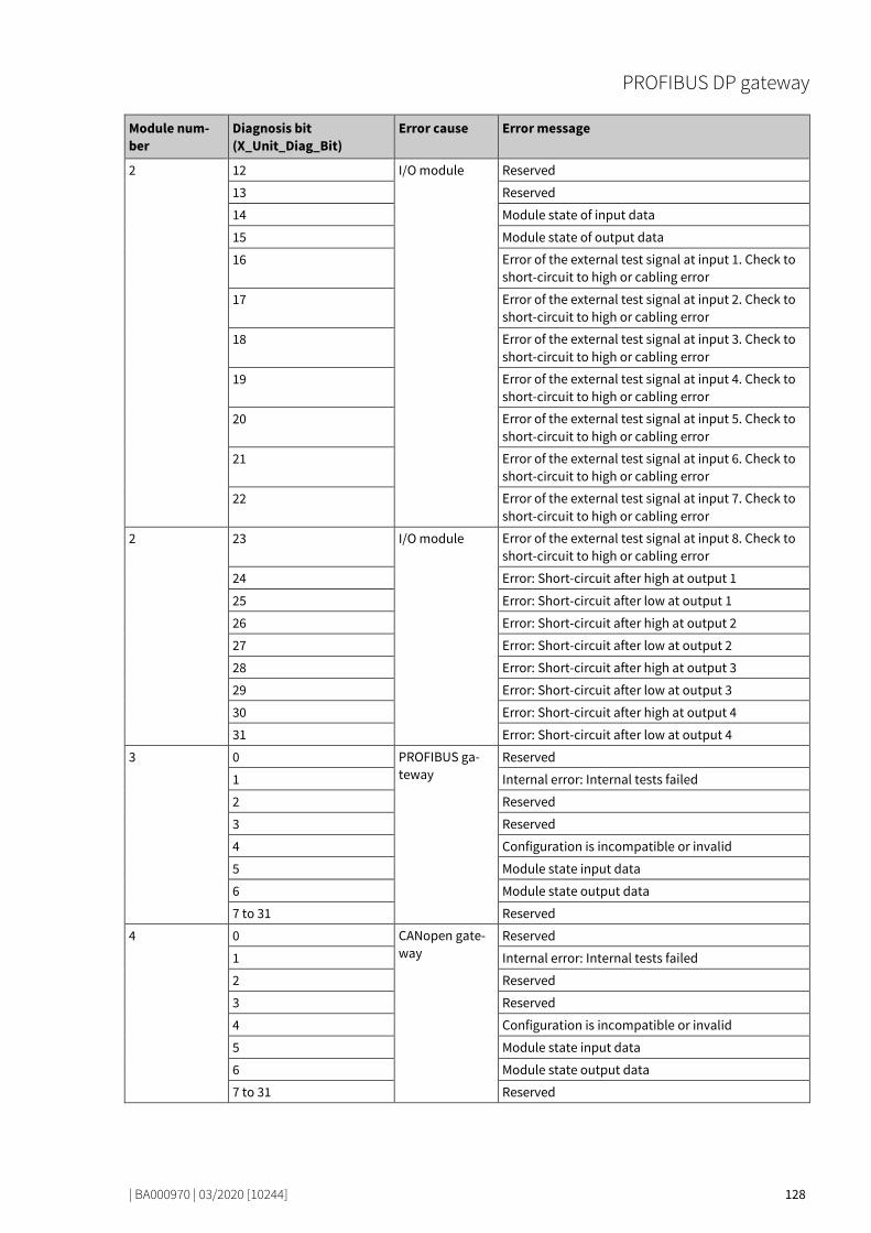
PROFIBUS DP gateway
| BA000970 | 03/2020 [10244] 128
Module num-ber
Diagnosis bit (X_Unit_Diag_Bit)
Error cause Error message
2 12 I/O module Reserved
13 Reserved
14 Module state of input data
15 Module state of output data
16 Error of the external test signal at input 1. Check to short-circuit to high or cabling error
17 Error of the external test signal at input 2. Check to short-circuit to high or cabling error
18 Error of the external test signal at input 3. Check to short-circuit to high or cabling error
19 Error of the external test signal at input 4. Check to short-circuit to high or cabling error
20 Error of the external test signal at input 5. Check to short-circuit to high or cabling error
21 Error of the external test signal at input 6. Check to short-circuit to high or cabling error
22 Error of the external test signal at input 7. Check to short-circuit to high or cabling error
2 23 I/O module Error of the external test signal at input 8. Check to short-circuit to high or cabling error
24 Error: Short-circuit after high at output 1
25 Error: Short-circuit after low at output 1
26 Error: Short-circuit after high at output 2
27 Error: Short-circuit after low at output 2
28 Error: Short-circuit after high at output 3
29 Error: Short-circuit after low at output 3
30 Error: Short-circuit after high at output 4
31 Error: Short-circuit after low at output 4
3 0 PROFIBUS ga-teway
Reserved
1 Internal error: Internal tests failed
2 Reserved
3 Reserved
4 Configuration is incompatible or invalid
5 Module state input data
6 Module state output data
7 to 31 Reserved
4 0 CANopen gate-way
Reserved
1 Internal error: Internal tests failed
2 Reserved
3 Reserved
4 Configuration is incompatible or invalid
5 Module state input data
6 Module state output data
7 to 31 Reserved

PROFIBUS DP gateway
| BA000970 | 03/2020 [10244] 129
Module num-ber
Diagnosis bit (X_Unit_Diag_Bit)
Error cause Error message
5 0 EtherCAT Gate-way
Reserved
1 Internal error: Internal tests failed
2 Reserved
3 Reserved
4 Configuration is incompatible or invalid
5 Module state input data
6 Module state output data
7 to 31 Reserved
6 0 Other module Reserved
1 Internal error: Internal tests failed
2 Reserved
3 Reserved
4 Configuration is incompatible or invalid
5 Reserved
6 Reserved
7 to 31 Reserved
7 0 Other module Reserved
1 Internal error: Internal tests failed
2 Reserved
3 Reserved
4 Configuration is incompatible or invalid
5 Reserved
6 Reserved
7 to 31 Reserved
8 0 Other module Reserved
1 Internal error: Internal tests failed
2 Reserved
3 Reserved
4 Configuration is incompatible or invalid
5 Reserved
6 Reserved
7 to 31 Reserved
9 0 EtherNet/IP, Modbus/TCP, PROFINET IO
Reserved
1 Internal error: Internal tests failed
2 Reserved
3 Reserved
4 Configuration is incompatible or invalid
5 Module state input data
6 Module state output data
7 to 31 Reserved

PROFIBUS DP gateway
| BA000970 | 03/2020 [10244] 130
Module num-ber
Diagnosis bit (X_Unit_Diag_Bit)
Error cause Error message
10 0 Other module Reserved
1 Internal error: Internal tests failed
2 Reserved
3 Reserved
4 Configuration is incompatible or invalid
5 to 31 Reserved
14 0 Unsecure IO Reserved
1 Internal error: Internal tests failed
2 Reserved
3 Reserved
4 Configuration is incompatible or invalid
5 Output power supply not in permitted range
6 to 31 Reserved

PROFIBUS DP gateway
| BA000970 | 03/2020 [10244] 131
Diagnosis and troubleshooting 78450955
You can find information on diagnosis of the samosPRO system in the software manual.
Table 81: Troubleshooting on the SP-PROFIBUS-DP module
Error Possible cause Possible remedy
Key: LED off / LED flashes / LED lights up
samosPLAN 6 cannot set up a connection to the sa-mosPRO gateway
The SP-PROFIBUS-DP module has no power supply
• Switch on the power supply. • Check the communication
settings in samosPLAN 6.
The SP-PROFIBUS-DP modu-le does not provide any data.
• Configuration required. • The configuration has not
yet been fully transmitted.
• Configure the SP-PROFIBUS-DP module and transfer the confi-guration to the system.
• Wait until the configuration has been fully transferred.
LED PWR Green
LED BF Off
MS LED - Red (1 Hz)
The SP-PROFIBUS-DP modu-le does not provide any data.
No data set was activated. Activate at least one data set.
LED PWR Green
LED BF Off
MS LED Green
The SP-PROFIBUS-DP modu-le does not provide any data.
The SP-PROFIBUS-DP module is in the Stop state.
• The controller modu-le/application is stopped.
• Start the controller module (switch to Run mode).
LED PWR Green
LED BF / Off / red
MS LED - Green (1 Hz)
The SP-PROFIBUS-DP modu-le does not provide any data.
PROFIBUS-Master is in stop mode
Set the PROFIBUS-Master to Run mode
LED PWR Green
LED BF Off
MS LED Green
The SP-PROFIBUS-DP func-tioned correctly after confi-guration but suddenly pro-vides no more data.
• The PROFIBUS hardware address of the SP-PROFIBUS-DP module was changed.
• The PROFIBUS line has been interrupted.
• Check the PROFIBUS address settings on the hardware.
• Check the PROFIBUS cabling. • Check the PROFIBUS master.
LED PWR Green
LED BF Red
MS LED /
Red / green
9.4

PROFIBUS DP gateway
| BA000970 | 03/2020 [10244] 132
Error Possible cause Possible remedy
The SP-PROFIBUS-DP modu-le is in the Critical error sta-te.
• Internal device error on the SP-PROFIBUS-DP mo-dule
• The module version of the controller module does not support any gateways.
• Switch the samosPRO system’s power supply off and on again.
• Check the diagnostic messages with the aid of the samos-PLAN 6.
• Use the controller module with the required module version.
• If the error persists, replace the gateway.
LED PWR Green
LED BF Red
MS LED
Red (2 Hz)
The SP-PROFIBUS-DP modu-le / the samosPRO system is in the “Critical error” state.
• The SP-PROFIBUS-DP module is not properly connected to the sa-mosPRO modules.
• The module connection plug is dirty or damaged.
• Another samosPRO modu-le has an internal critical error.
• Plug the SP-PROFIBUS-DP module in correctly.
• Clean the connection plug and socket.
• Switch on the power supply again.
• Check the other samosPRO modules.
LED PWR LED BF Off
MS LED

CANopen gateway
| BA000970 | 03/2020 [10244] 133
CANOPEN GATEWAY
78526987
The following samosPRO gateway can be used for CANopen: • SP-CANopen
Interfaces and operation 78535947
Operating and display elements
Illustration 34: Operating and display elements of the SP-CANopen module
Table 82: Reference: State LEDs of the SP-CANopen module
LED Meaning
Key: LED off / LED flashes / LED lights up
PWR Power
Off No power supply
Green Ready for operation, power supply switched on
Red System error
NS (net-work status)
Off CANopen state: stopped (except for node guarding and heartbeat, when activated)
Green CANopen state: Ready for operation (PDO and SDO data exchange)
Green CANopen state: Pre-operational (only SDO data exchange)
Red CAN-Bus off (hardware problem on CAN - physical layer) or error passive
Red (1 Hz)
Node guarding failed (NMT master no longer monitors the slave) or heartbeat consumer failure
10
10.1

CANopen gateway
| BA000970 | 03/2020 [10244] 134
LED Meaning
MS (module status)
Off Switch on
Green Executing, internal safety bus and PDO status: all "Good"
Green Idle (cable not connected or node guarding failed)
/ Red / green
Executing, internal safety bus and PDO status: at least one "Bad"
Red Critical error, caused by emergency bit
Red (1 Hz)
Configuration required or is taking place right now
Red (2 Hz)
Critical error, caused by gateway itself
Further information: Diagnostics and troubleshooting [ch. 10.13, p. 165]
NOTICE • To allow the PLC to detect the SP-CANopen module as bus participant, the PLC must already be started up, before the samosPRO system is switched on.
• If a PLC is stopped or is switched off then the SP-CANopen module can go into the Error passi-ve or CAN Bus Off states. In these cases the samosPRO system must be reset before reuse with a PLC.
How to set the CANopen address with the aid of the hardware address switches Set the CANopen address switches using the hardware address switches at the front of the sys-
tem. Switch the samosPRO system off and on again.
Table 83: Address switch on the SP-CANopen module
Switches Function
× 10 Address switch 1 Rotary switch with 10 positions for setting the module address (in tens)
× 1 Address switch 2 Rotary switch with 10 positions for setting the module address (in units)
How to set the baud rate with the aid of the hardware DIP switches: Set the baud rate using the DIP switches on the equipment. Switch the samosPRO system off and on again.
Illustration 35: Setting the DIP switches on the SP-CANopen module
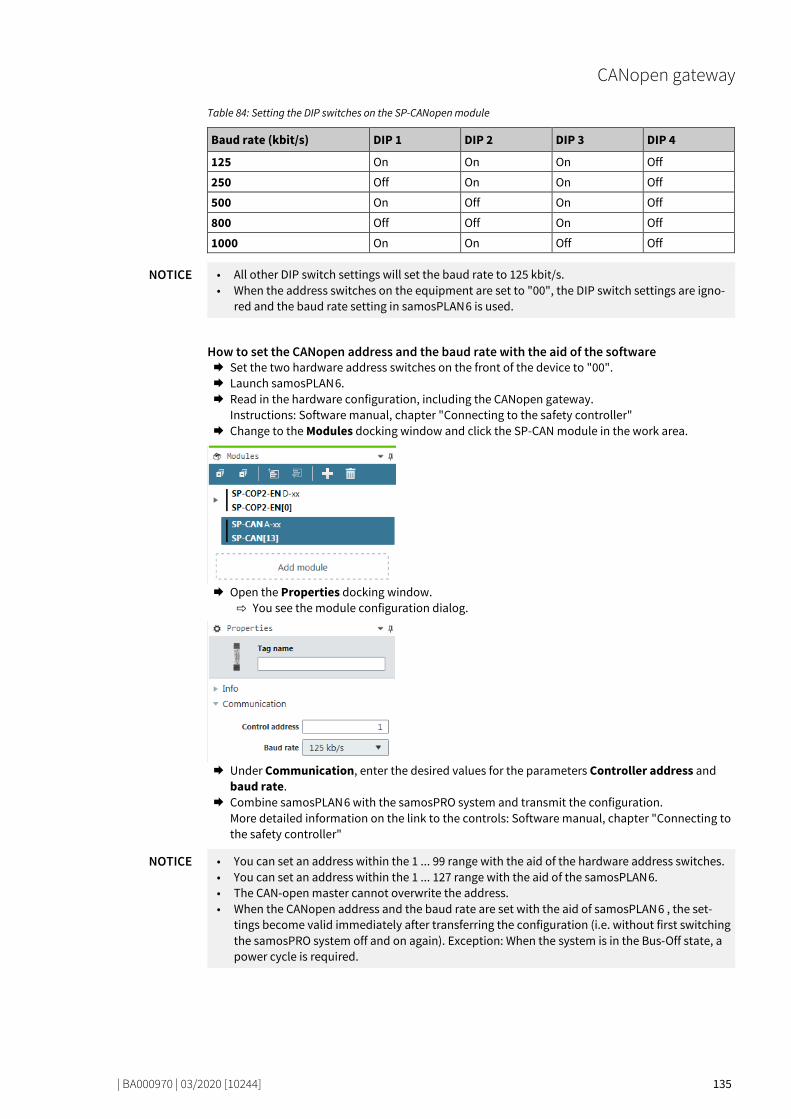
CANopen gateway
| BA000970 | 03/2020 [10244] 135
Table 84: Setting the DIP switches on the SP-CANopen module
Baud rate (kbit/s) DIP 1 DIP 2 DIP 3 DIP 4
125 On On On Off
250 Off On On Off
500 On Off On Off
800 Off Off On Off
1000 On On Off Off
NOTICE • All other DIP switch settings will set the baud rate to 125 kbit/s. • When the address switches on the equipment are set to "00", the DIP switch settings are igno-
red and the baud rate setting in samosPLAN 6 is used.
How to set the CANopen address and the baud rate with the aid of the software Set the two hardware address switches on the front of the device to "00". Launch samosPLAN 6. Read in the hardware configuration, including the CANopen gateway.
Instructions: Software manual, chapter "Connecting to the safety controller" Change to the Modules docking window and click the SP-CAN module in the work area.
Open the Properties docking window.
You see the module configuration dialog.
Under Communication, enter the desired values for the parameters Controller address and
baud rate. Combine samosPLAN 6 with the samosPRO system and transmit the configuration.
More detailed information on the link to the controls: Software manual, chapter "Connecting to the safety controller"
NOTICE • You can set an address within the 1 ... 99 range with the aid of the hardware address switches. • You can set an address within the 1 ... 127 range with the aid of the samosPLAN 6. • The CAN-open master cannot overwrite the address. • When the CANopen address and the baud rate are set with the aid of samosPLAN 6 , the set-
tings become valid immediately after transferring the configuration (i.e. without first switching the samosPRO system off and on again). Exception: When the system is in the Bus-Off state, a power cycle is required.
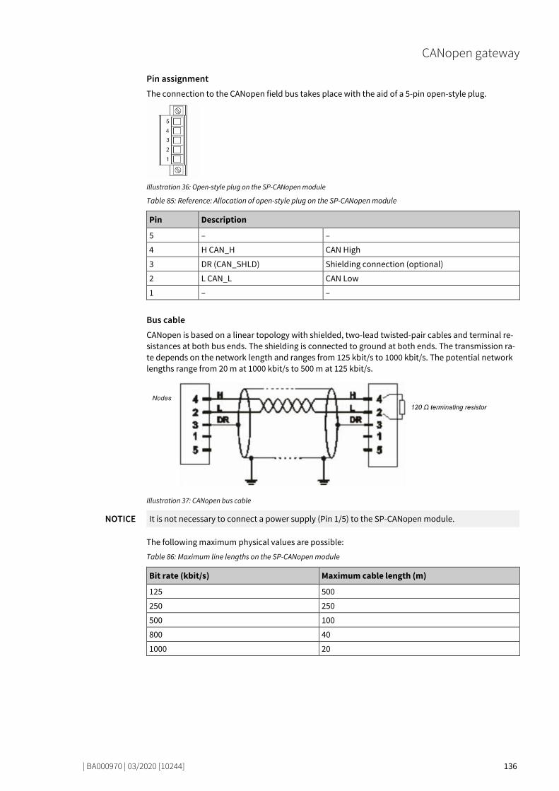
CANopen gateway
| BA000970 | 03/2020 [10244] 136
Pin assignment The connection to the CANopen field bus takes place with the aid of a 5-pin open-style plug.
Illustration 36: Open-style plug on the SP-CANopen module
Table 85: Reference: Allocation of open-style plug on the SP-CANopen module
Pin Description
5 – –
4 H CAN_H CAN High
3 DR (CAN_SHLD) Shielding connection (optional)
2 L CAN_L CAN Low
1 – –
Bus cable CANopen is based on a linear topology with shielded, two-lead twisted-pair cables and terminal re-sistances at both bus ends. The shielding is connected to ground at both ends. The transmission ra-te depends on the network length and ranges from 125 kbit/s to 1000 kbit/s. The potential network lengths range from 20 m at 1000 kbit/s to 500 m at 125 kbit/s.
Illustration 37: CANopen bus cable
NOTICE It is not necessary to connect a power supply (Pin 1/5) to the SP-CANopen module.
The following maximum physical values are possible:
Table 86: Maximum line lengths on the SP-CANopen module
Bit rate (kbit/s) Maximum cable length (m)
125 500
250 250
500 100
800 40
1000 20

CANopen gateway
| BA000970 | 03/2020 [10244] 137
EDS file The equipment characteristics are described with the aid of the electronic data sheet (EDS) file), that makes use of any standard bus configuration tool.
You will fin the EDS file and the equipment symbol for integration into a PLC of the product website of the SP-CANopen module on the Internet (https://eshop.wieland-electric.com/).

CANopen gateway
| BA000970 | 03/2020 [10244] 138
CANopen configuration of the gateway - how the data are transferred 78571659
NOTICE This documentation does not address the installation of the CANopen network or the other com-ponents of the automation system project in the network configuration tool. It is assumed that the CANopen project in the configuration program, e.g. 3S Software CoDeSys 2.x, has already been set up. The examples presented are based on configurations created with the help of CoDeSys 2.3.
The following steps are required to configure the communication between the PLC and the gateway.
Step 1: Install the electronic data sheet (EDS file) Before the SP-CANopen module can be used for the first time as equipment in the network configu-ration tool, e.g. CoDeSys 2.3, the electronic data sheet (EDS file) of the gateway must first be instal-led in the hardware catalog of the tool. Download the EDS file and the equipment symbol from the product site of the SP-CANopen mo-
dule (https://eshop.wieland-electric.com/). Follow the instructions for the installation of EDS files in the online help section or in the user
manual for the CANopen network configuration tool.
Example – How to install the EDS file with CoDeSys 2.3: Open the window for editing the control configuration.
Illustration 38: CoDeSys editing window for control configuration
Choose the command Add configuration file... from the Extras menu. A file selection window is opened.
Select the EDS file of the SP-CANopen module and click the Open button.
10.2
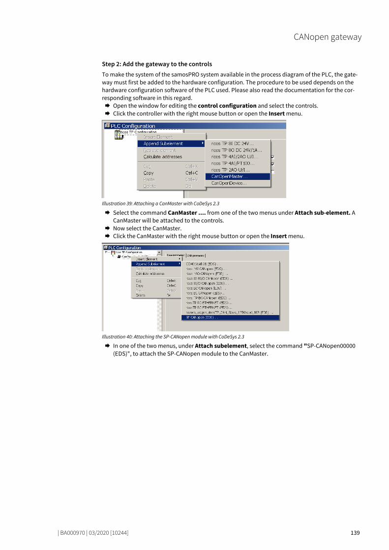
CANopen gateway
| BA000970 | 03/2020 [10244] 139
Step 2: Add the gateway to the controls To make the system of the samosPRO system available in the process diagram of the PLC, the gate-way must first be added to the hardware configuration. The procedure to be used depends on the hardware configuration software of the PLC used. Please also read the documentation for the cor-responding software in this regard. Open the window for editing the control configuration and select the controls. Click the controller with the right mouse button or open the Insert menu.
Illustration 39: Attaching a CanMaster with CoDeSys 2.3
Select the command CanMaster .... from one of the two menus under Attach sub-element. A CanMaster will be attached to the controls.
Now select the CanMaster. Click the CanMaster with the right mouse button or open the Insert menu.
Illustration 40: Attaching the SP-CANopen module with CoDeSys 2.3
In one of the two menus, under Attach subelement, select the command "SP-CANopen00000 (EDS)", to attach the SP-CANopen module to the CanMaster.
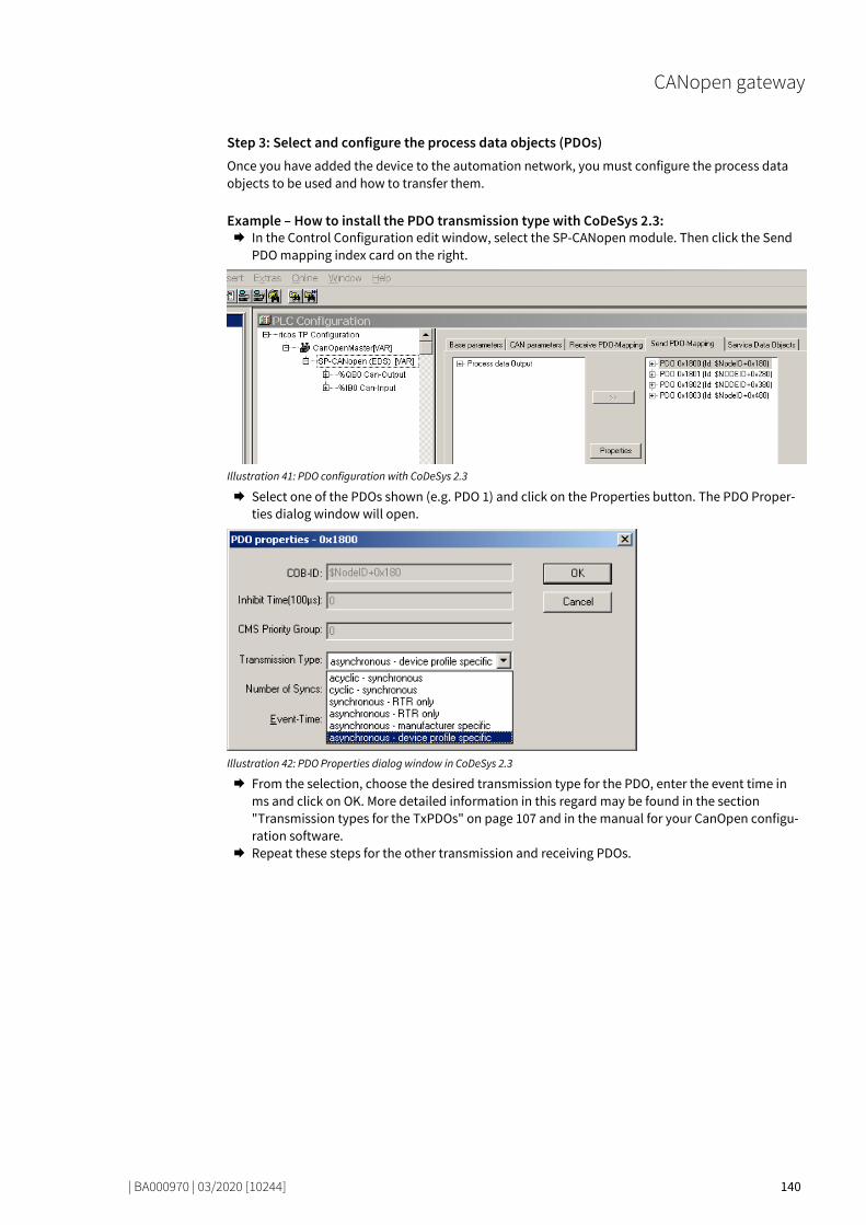
CANopen gateway
| BA000970 | 03/2020 [10244] 140
Step 3: Select and configure the process data objects (PDOs) Once you have added the device to the automation network, you must configure the process data objects to be used and how to transfer them.
Example – How to install the PDO transmission type with CoDeSys 2.3: In the Control Configuration edit window, select the SP-CANopen module. Then click the Send
PDO mapping index card on the right.
Illustration 41: PDO configuration with CoDeSys 2.3
Select one of the PDOs shown (e.g. PDO 1) and click on the Properties button. The PDO Proper-ties dialog window will open.
Illustration 42: PDO Properties dialog window in CoDeSys 2.3
From the selection, choose the desired transmission type for the PDO, enter the event time in ms and click on OK. More detailed information in this regard may be found in the section "Transmission types for the TxPDOs" on page 107 and in the manual for your CanOpen configu-ration software.
Repeat these steps for the other transmission and receiving PDOs.
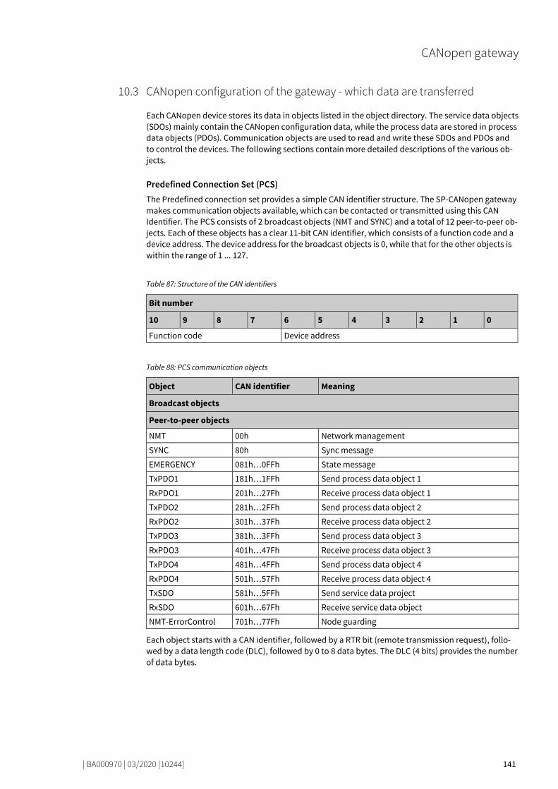
CANopen gateway
| BA000970 | 03/2020 [10244] 141
CANopen configuration of the gateway - which data are transferred 78591627
Each CANopen device stores its data in objects listed in the object directory. The service data objects (SDOs) mainly contain the CANopen configuration data, while the process data are stored in process data objects (PDOs). Communication objects are used to read and write these SDOs and PDOs and to control the devices. The following sections contain more detailed descriptions of the various ob-jects.
Predefined Connection Set (PCS) The Predefined connection set provides a simple CAN identifier structure. The SP-CANopen gateway makes communication objects available, which can be contacted or transmitted using this CAN Identifier. The PCS consists of 2 broadcast objects (NMT and SYNC) and a total of 12 peer-to-peer ob-jects. Each of these objects has a clear 11-bit CAN identifier, which consists of a function code and a device address. The device address for the broadcast objects is 0, while that for the other objects is within the range of 1 ... 127.
Table 87: Structure of the CAN identifiers
Bit number
10 9 8 7 6 5 4 3 2 1 0
Function code Device address
Table 88: PCS communication objects
Object CAN identifier Meaning
Broadcast objects
Peer-to-peer objects
NMT 00h Network management
SYNC 80h Sync message
EMERGENCY 081h…0FFh State message
TxPDO1 181h…1FFh Send process data object 1
RxPDO1 201h…27Fh Receive process data object 1
TxPDO2 281h…2FFh Send process data object 2
RxPDO2 301h…37Fh Receive process data object 2
TxPDO3 381h…3FFh Send process data object 3
RxPDO3 401h…47Fh Receive process data object 3
TxPDO4 481h…4FFh Send process data object 4
RxPDO4 501h…57Fh Receive process data object 4
TxSDO 581h…5FFh Send service data project
RxSDO 601h…67Fh Receive service data object
NMT-ErrorControl 701h…77Fh Node guarding
Each object starts with a CAN identifier, followed by a RTR bit (remote transmission request), follo-wed by a data length code (DLC), followed by 0 to 8 data bytes. The DLC (4 bits) provides the number of data bytes.
10.3
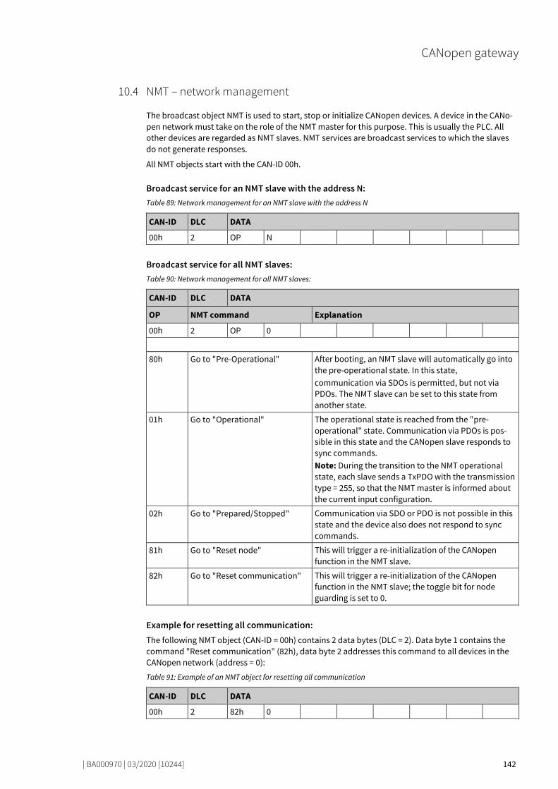
CANopen gateway
| BA000970 | 03/2020 [10244] 142
NMT – network management 78602635
The broadcast object NMT is used to start, stop or initialize CANopen devices. A device in the CANo-pen network must take on the role of the NMT master for this purpose. This is usually the PLC. All other devices are regarded as NMT slaves. NMT services are broadcast services to which the slaves do not generate responses.
All NMT objects start with the CAN-ID 00h.
Broadcast service for an NMT slave with the address N: Table 89: Network management for an NMT slave with the address N
CAN-ID DLC DATA
00h 2 OP N
Broadcast service for all NMT slaves: Table 90: Network management for all NMT slaves:
CAN-ID DLC DATA
OP NMT command Explanation
00h 2 OP 0
80h Go to "Pre-Operational" After booting, an NMT slave will automatically go into the pre-operational state. In this state, communication via SDOs is permitted, but not via PDOs. The NMT slave can be set to this state from another state.
01h Go to "Operational" The operational state is reached from the "pre-operational" state. Communication via PDOs is pos-sible in this state and the CANopen slave responds to sync commands. Note: During the transition to the NMT operational state, each slave sends a TxPDO with the transmission type = 255, so that the NMT master is informed about the current input configuration.
02h Go to "Prepared/Stopped" Communication via SDO or PDO is not possible in this state and the device also does not respond to sync commands.
81h Go to "Reset node" This will trigger a re-initialization of the CANopen function in the NMT slave.
82h Go to "Reset communication" This will trigger a re-initialization of the CANopen function in the NMT slave; the toggle bit for node guarding is set to 0.
Example for resetting all communication: The following NMT object (CAN-ID = 00h) contains 2 data bytes (DLC = 2). Data byte 1 contains the command "Reset communication" (82h), data byte 2 addresses this command to all devices in the CANopen network (address = 0):
Table 91: Example of an NMT object for resetting all communication
CAN-ID DLC DATA
00h 2 82h 0
10.4

CANopen gateway
| BA000970 | 03/2020 [10244] 143
SYNC 78621835
The SYNC command results in all TxPDOs of a CANopen slave being sent. It is thus possible to prompt the slave with the aid of SYNC.
Table 92: Prompting of inputs with the aid of SYNC
CAN-ID DLC DATA
80h 0
The slave sends all input values when he receives this command. All TxPDOs are sent.
To ensure that the slave automatically sends the current input values when receiving a SYNC com-mand, the transmission type for the relevant PDOs must be set to 1 (cyclic, synchronous). In additi-on, the device must be in the "operational" state.
It is possible to amend the transmission type for the TxPDOs with the aid of the SDOs 1800 … 1803 (PDO communication parameter) and to amend Sub-Object 2. The following types are permitted: • Acyclic/synchronous = 0 • Cyclic/synchronous = 1 = 1 ... 240 • Acyclic once device profile = 255 (only for TxPDO 1 … 4, digital inputs)
Emergency 78827659
A CANopen slave with the address N sends an emergency message to inform the other devices of an error state.
Table 93: Emergency messages
CAN-ID DLC DATA
80h + N 8 ErrL ErrH Err-Reg
M1 M2 M3 M4 M5
ErrL, ErrH Emergency error code, 16-bit Low Byte/High Byte 7001h … 7003h: General error
Err-Reg Error register, CANopen object SDO 1001h
M1 Module index M1 (corresponds to the module address in the module list) of the module causing the error. The module number can be determined using the subindex (= M1 + 1) of SDO 1027. The module number is used as an index for the status bits (see below: Table “CANopen Emergency Messages").
M2 … M5 4 bytes, module-specific state bits. Active bits are high (= "1"). (see below: Table “CANopen Emergency Messages")
10.5
10.6
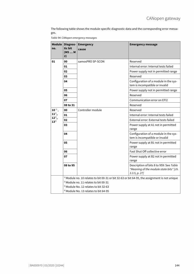
CANopen gateway
| BA000970 | 03/2020 [10244] 144
The following table shows the module-specific diagnostic data and the corresponding error messa-ges.
Table 94: CANopen emergency messages
Module no.
Diagnos-tic bit (M5 … M2)
Emergency cause
Emergency message
01 00 samosPRO SP-SCON Reserved
01 Internal error: Internal tests failed
02 Power supply not in permitted range
03 Reserved
04 Configuration of a module in the sys-tem is incompatible or invalid
05 Power supply not in permitted range
06 Reserved
07 Communication error on EFI2
08 to 31 Reserved
10 1) , 112), 123), 134)
00 Controller module Reserved
01 Internal error: Internal tests failed
02 External error: External tests failed
03 Power supply at A1 not in permitted range
04 Configuration of a module in the sys-tem is incompatible or invalid
05 Power supply at B1 not in permitted range
06 Fast Shut Off collective error
07 Power supply at B2 not in permitted range
08 to 95 Description of bits 8 to 959: See Table "Meaning of the module state bits" [ch. 3.3.5, p. 27]
1) Module no. 10 relates to bit 00-31 or bit 32-63 or bit 64-95, the assignment is not unique 2) Module no. 11 relates to bit 00-31 3) Module No. 12 relates to bit 32-63 4) Module No. 13 relates to bit 64-95

CANopen gateway
| BA000970 | 03/2020 [10244] 145
Module no.
Diagnos-tic bit (M5 … M2)
Emergency cause
Emergency message
02 00 Secure I/O modules Reserved
01 Internal error: Internal tests failed
02 External error: External tests failed
03 Error history element exists: Access with configuration tool
04 Configuration is incompatible or inva-lid
05 Output power supply not in permitted range
06 Reserved
07 Reserved
08 Dual-channel evaluation of input 1-2: Error detected
09 Dual-channel evaluation of input 3-4: Error detected
02 10 Secure I/O modules Dual-channel evaluation of input 5-6: Error detected
11 Dual-channel evaluation of input 7-8: Error detected
12 Reserved
13 Reserved
14 Module state input data
15 Module state output data
16 Error of the external test signal at input 1. Check whether there is a short-circuit to High or a cabling error
17 Error of the external test signal at input 2. Check whether there is a short-circuit to High or a cabling error
18 Error of the external test signal at input 3. Check whether there is a short-circuit to High or a cabling error
19 Error of the external test signal at input 4. Check whether there is a short-circuit to High or a cabling error
20 Error of the external test signal at input 5. Check whether there is a short-circuit to High or a cabling error
21 Error of the external test signal at input 6. Check whether there is a short-circuit to High or a cabling error

CANopen gateway
| BA000970 | 03/2020 [10244] 146
Module no.
Diagnos-tic bit (M5 … M2)
Emergency cause
Emergency message
02 22 Secure I/O modules Error of the external test signal at input 7. Check whether there is a short-circuit to High or a cabling error
23 Error of the external test signal at input 8. Check whether there is a short-circuit to High or a cabling error
24 Error: Short-circuit after high at out-put 1
25 Error: Short-circuit after low at output 1
26 Error: Short-circuit after high at out-put 2
27 Error: Short-circuit after low at output 2
28 Error: Short-circuit after high at out-put 3
29 Error: Short-circuit after low at output 3
30 Error: Short-circuit after high at out-put 4
31 Error: Short-circuit after low at output 4
03 00 PROFIBUS gateway Reserved
01 Internal error: Internal tests failed
02 Reserved
03 Reserved
04 Configuration is incompatible or inva-lid
05 Module state input data
06 Module state output data
07 to 31 Reserved
04 00 CANopen gateway
Reserved
01 Internal error: Internal tests failed
02 Reserved
03 Reserved
04 Configuration is incompatible or inva-lid
05 Module state input data
06 Module state output data
07 to 31 Reserved
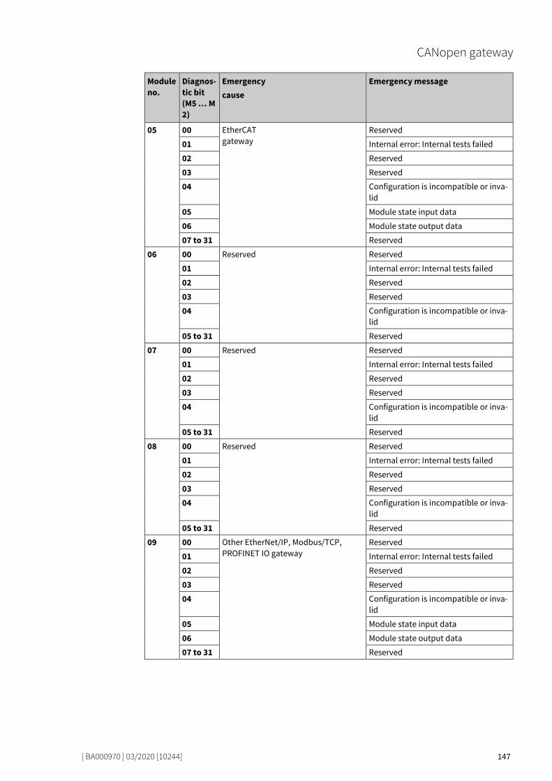
CANopen gateway
| BA000970 | 03/2020 [10244] 147
Module no.
Diagnos-tic bit (M5 … M2)
Emergency cause
Emergency message
05 00 EtherCAT gateway
Reserved
01 Internal error: Internal tests failed
02 Reserved
03 Reserved
04 Configuration is incompatible or inva-lid
05 Module state input data
06 Module state output data
07 to 31 Reserved
06 00 Reserved Reserved
01 Internal error: Internal tests failed
02 Reserved
03 Reserved
04 Configuration is incompatible or inva-lid
05 to 31 Reserved
07 00 Reserved Reserved
01 Internal error: Internal tests failed
02 Reserved
03 Reserved
04 Configuration is incompatible or inva-lid
05 to 31 Reserved
08 00 Reserved Reserved
01 Internal error: Internal tests failed
02 Reserved
03 Reserved
04 Configuration is incompatible or inva-lid
05 to 31 Reserved
09 00 Other EtherNet/IP, Modbus/TCP, PROFINET IO gateway
Reserved
01 Internal error: Internal tests failed
02 Reserved
03 Reserved
04 Configuration is incompatible or inva-lid
05 Module state input data
06 Module state output data
07 to 31 Reserved

CANopen gateway
| BA000970 | 03/2020 [10244] 148
Module no.
Diagnos-tic bit (M5 … M2)
Emergency cause
Emergency message
14 00 Unsecure IO Reserved
01 Internal error: Internal tests failed
02 Reserved
03 Reserved
04 Configuration is incompatible or inva-lid
05 Output power supply not in permitted range
06 to 31 Reserved
NOTICE The allocation of the diagnostic bits for M2 to M5 is as follows:
Bit 0 Bit 1 … Bit 7 Bit 8 … Bit31
M5.0 M5.1 … M5.7 M4.0 … M2.7

CANopen gateway
| BA000970 | 03/2020 [10244] 149
Node guarding 78633995
An NMT master (e.g. a PLC with integrated CANopen master) uses the NMT-Error-Control object to detect a failure of an NMT slave with the
address N. The NMT slave must respond to the query of the NMT master within the node guarding time. The node guarding time must be monitored by the NMT master.
The NMT master sends a CAN message with the identifier <700h + node ID> and RTRBit (remote transmission request).
Query of NMT master:
Table 95: Query of NMT master
CAN-ID RTR DLC DATA
700h + N 1 0
The slave (e.g. the SP-CANopen module) then sends a state byte 1 with the following content:
Response of the slave:
Table 96: Response of the slave
CAN-ID DLC DATA
700h + N 1 Byte1
Table 97: Remote transmission request
Bit Meaning
7 Toggle bit changes its value between two consecutive queries
6…0 NMT status 4 = Stopped 5 = Operational 127 = Pre-operational
Bootup On booting, the gateway sends a bootup message with the CAN-ID 700h+N, DLC = 1 and byte 1 = 0.
Heartbeat producer When the gateway has been configured as a heartbeat producer (i.e. when SDO 1017 contains a va-lue for the producer heartbeat time, see table "Supported SDOs" [ch. 10.10, p. 154]), then sends a cyc-lical message with the CAN-ID 700h+N, DLC = 1 and Byte 1 = 05h. The toggle bit (bit 7) is always 0.
Heartbeat consumer When the gateway has been configured as a heartbeat consumer (i.e. when SDO 1016.1 contains a value for the consumer heartbeat time, see table "Supported SDOs" [ch. 10.10, p. 154]), then at least one node guarding message must be received within the configured consumer heartbeat time (typi-cally from a NMT master).
10.7

CANopen gateway
| BA000970 | 03/2020 [10244] 150
PDO communication 78647307
Process data objects (PDOs) are the real-time objects of the CANopen field bus. They are sent wit-hout a protocol overhead, i.e. the receiver sends no confirmation.
The SP-CANopen module provides for transmit process data objects (TxPDOs), which contain the operating
process data to be sent to the network, and four receive process
data objects (RxPDOs) for the process data received from the network.
CANopen objects are addressed with the aid of 11-bit CAN identifiers. As a pre-set, the CAN identifier derives each object from the object type and the configured CANopen device address. The CAN iden-tifier of the PDOs can be changed by using SDOs 1400 to 1403 for the RxPDOs and SDOs 1800 to 1803 for the TxPDOs ("PDO linking").
NOTICE Each process data object contains 8 bytes.
The content of the process data objects can be freely selected, but has been preconfigured as follows in samosPLAN 6:
Table 98: Preset for the content of the transmit process data objects (TxPDOs) of the SP-CANopen module
PDO#1 PDO#2 PDO#3 PDO#4
Output data - Block 1 Output data - Block 2
Output data - Block 3
Output data - Block 4
Byte 0 Input values for Module 0 (I1..I8)
Input values for Module 1
Input values for Module 9
Output values for Module 5
Byte 1 Input values for Module 0 (I9..I16)
Input values for Module 2
Input values for Module 10
Output values for Module 6
Byte 2 Input values for Module 0 (IQ1..IQ4)
Input values for Module 3
Input values for Module 11
Output values for Module 7
Byte 3 Output values for Mo-dule 0 (Q1..Q4,IQ1-IQ4)
Input values for Module 4
Input values for Module 12
Output values for Module 8
Byte 4 Direct data (Off) 1 Input values for Module 5
Output values for Module 1
Output values for Module 9
Byte 5 Direct data (Off) 2 Input values for Module 6
Output values for Module 2
Output values for Module 10
Byte 6 Direct data (Off) 3 Input values for Module 7
Output values for Module 3
Output values for Module 11
Byte 7 Direct data (Off) 4 Input values for Module 8
Output values for Module 4
Output values for Module 12
Detailed information about the content of the process diagram may be found here: Configuring the gateway output values (tab 1) [ch. 5.4, p. 49]
You will find further information about how to configure the process diagram here: • Configuration of gateways with samosPLAN 6 [ch. 5, p. 40] • Software manual
NOTICE • The process data can also be written and read with the aid of service data objects SDO 6000 and SDO 6200 (see SDO communication [ch. 10.9, p. 152]). Easy access via SDO is recommended for diagnostic purposes. More rapid PDO communication is to be used for normal operation.
• After starting up or changing the configuration (either with the aid of the CANopen master or with samosPLAN 6), the LED MS of the CANopen gateway flashes red/green until an initial transmit/receive data exchange has taken place via PDO or SDO 6000/SDO 6200 in the CANo-pen network.
10.8

CANopen gateway
| BA000970 | 03/2020 [10244] 151
TxPDO 1…4 A transmit-PDO transmits data from the CANopen gateway to a CANopen device.
Table 99: TxPDO 1…4
CAN ID DLC Data
181-1FF 8 B1 B2 B3 B4 B5 B6 B7 B8
281-2FF 8 B9 B10 B11 B12 B13 B14 B15 B16
381-3FF 8 B17 B18 B19 B20 B21 B22 B23 B24
481-4FF 8 B25 B26 B27 B28 B29 B30 B31 B32
B1…B32: CAN telegram bytes as in the network input data, with the aid of samosPLAN 6 (see Confi-guring the gateway output values (tab 1) [ch. 5.4, p. 49]).
The gateway sends one or several TxPDOs when at least one of the following events occurs: • At least one input or output byte has changed its value and the transmission type for the TxPDO
that contains this byte has the value 255. • At least one input or output byte has changed its value and the gateway contains a SYNC com-
mand and at least one TxPDO has transmission type 0. • When the transmission type is n = 1 ... 240, n sync commands are required in order to send the
TxPDO. • The transmission type for a TxPDO is 254 or 255 and the event timer (SDO 1800,5 for TxPDO1)
has a value of N > 0. In this case this TxPDO is sent every N ms. • A TxPDO can also be called up with the aid of a remote transmission request (RTR). This requires
a CAN telegram to the gateway that contains the CAN-ID of the desired TxPDOs with DLC = 0 and RTR = 1.
The operating state of the device must be "operational" for all transmission methods (see Table "Network management for all NMT slaves" [ch. 10.4, p. 142]).
RxPDO 1…4 A receive-PDO transmits data from a CANopen device to the CANopen gateway.
Table 100: RxPDO 1…4
CAN ID DLC Data
201-1FF 8 B1 B2 B3 B4 B5 B6 B7 B8
301-2FF 8 B9 B10 B11 B12 B13 B14 B15 B16
401-3FF 8 B17 B18 B19 B20 B21 B22 B23 B24
501-4FF 8 B25 B26 B27 B28 B29 B30 B31 B32
B1…B32: CAN telegram bytes as for the gateway input data, with the aid of samosPLAN 6.
The transmission type 255 is preset for all RxPDOs. This means that the gateway immediately transmits the RxPDO data on to the controller module. This setting cannot be changed.
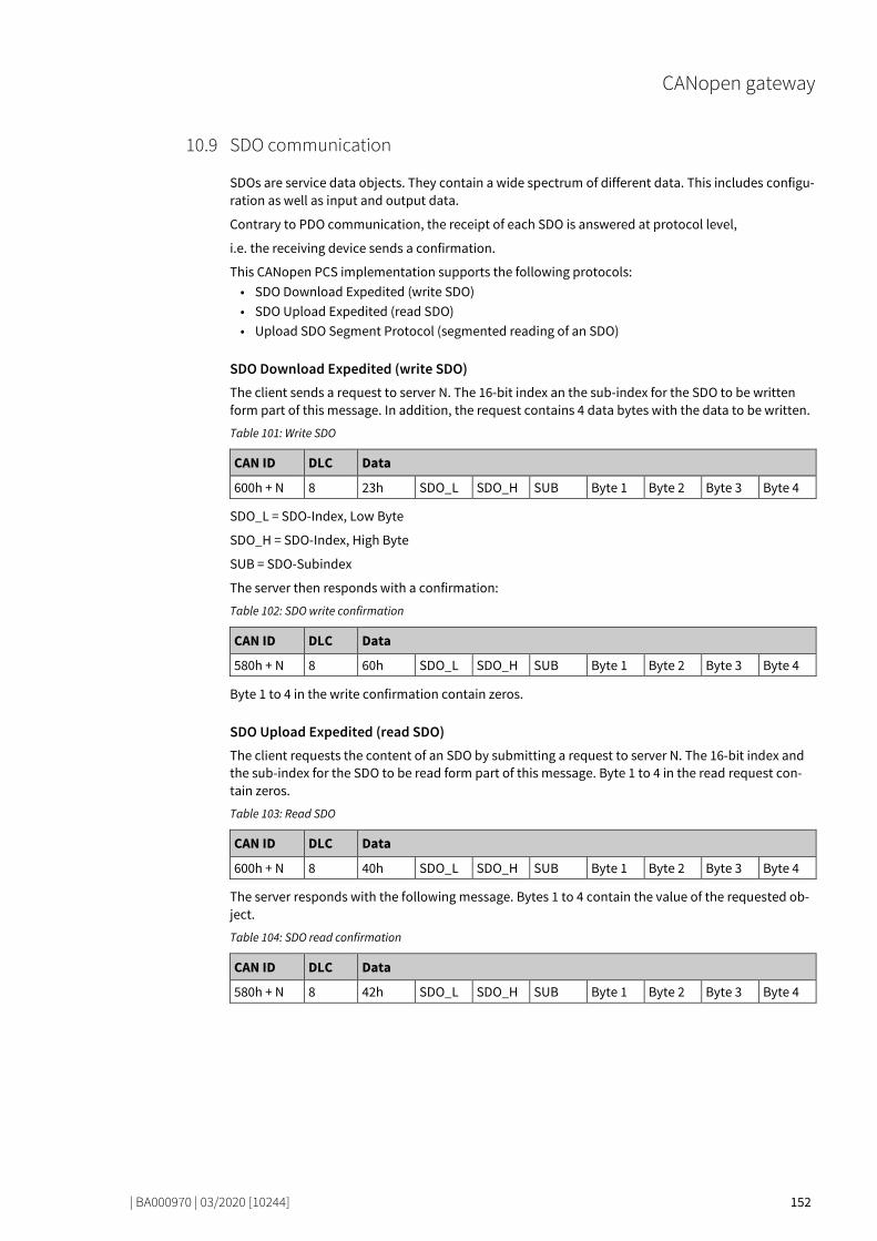
CANopen gateway
| BA000970 | 03/2020 [10244] 152
SDO communication 78671883
SDOs are service data objects. They contain a wide spectrum of different data. This includes configu-ration as well as input and output data.
Contrary to PDO communication, the receipt of each SDO is answered at protocol level,
i.e. the receiving device sends a confirmation.
This CANopen PCS implementation supports the following protocols: • SDO Download Expedited (write SDO) • SDO Upload Expedited (read SDO) • Upload SDO Segment Protocol (segmented reading of an SDO)
SDO Download Expedited (write SDO) The client sends a request to server N. The 16-bit index an the sub-index for the SDO to be written form part of this message. In addition, the request contains 4 data bytes with the data to be written.
Table 101: Write SDO
CAN ID DLC Data
600h + N 8 23h SDO_L SDO_H SUB Byte 1 Byte 2 Byte 3 Byte 4
SDO_L = SDO-Index, Low Byte
SDO_H = SDO-Index, High Byte
SUB = SDO-Subindex
The server then responds with a confirmation:
Table 102: SDO write confirmation
CAN ID DLC Data
580h + N 8 60h SDO_L SDO_H SUB Byte 1 Byte 2 Byte 3 Byte 4
Byte 1 to 4 in the write confirmation contain zeros.
SDO Upload Expedited (read SDO) The client requests the content of an SDO by submitting a request to server N. The 16-bit index and the sub-index for the SDO to be read form part of this message. Byte 1 to 4 in the read request con-tain zeros.
Table 103: Read SDO
CAN ID DLC Data
600h + N 8 40h SDO_L SDO_H SUB Byte 1 Byte 2 Byte 3 Byte 4
The server responds with the following message. Bytes 1 to 4 contain the value of the requested ob-ject.
Table 104: SDO read confirmation
CAN ID DLC Data
580h + N 8 42h SDO_L SDO_H SUB Byte 1 Byte 2 Byte 3 Byte 4
10.9
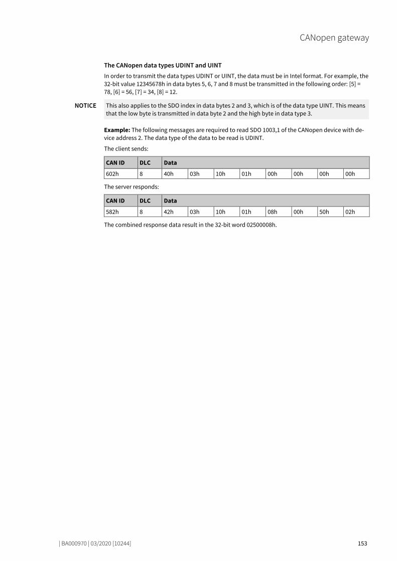
CANopen gateway
| BA000970 | 03/2020 [10244] 153
The CANopen data types UDINT and UINT In order to transmit the data types UDINT or UINT, the data must be in Intel format. For example, the 32-bit value 12345678h in data bytes 5, 6, 7 and 8 must be transmitted in the following order: [5] = 78, [6] = 56, [7] = 34, [8] = 12.
NOTICE This also applies to the SDO index in data bytes 2 and 3, which is of the data type UINT. This means that the low byte is transmitted in data byte 2 and the high byte in data type 3.
Example: The following messages are required to read SDO 1003,1 of the CANopen device with de-vice address 2. The data type of the data to be read is UDINT.
The client sends:
CAN ID DLC Data
602h 8 40h 03h 10h 01h 00h 00h 00h 00h
The server responds:
CAN ID DLC Data
582h 8 42h 03h 10h 01h 08h 00h 50h 02h
The combined response data result in the 32-bit word 02500008h.

CANopen gateway
| BA000970 | 03/2020 [10244] 154
SDO object directory 78681739
Each CANopen device manages its SDOs in an object directory. The complete
object directory is formally described in an EDS file. Many CANopen tools can ready this EDS file and therefore know the object characteristics of the CANopen device.
The following table shows all SDOs for the SP-CANopen gateway.
Table 105: Supported SDOs
SDO # Type
1000 Device type
1001 Error register
1003 Error list (error history)
1005 COB ID SYNC
1008 Device name
1009 Hardware version
100A Software version
100C Guard Time
100D Life Time Factor
1016 Consumer Heartbeat Time
1017 Producer Heartbeat Time
1018 Identification
1027 Module list
1400…1403 Communication parameter for RxPDO 1 … 4
1600…1603 Mapping parameter for RxPDO 1 … 4
1800…1803 Communication parameter for TxPDO 1 … 4
1A00…1A03 Mapping parameter for TxPDO 1 … 4
3100 Module status bits
3200 Config-CRC
3300 Module type code
6000 Process data input objects
6200 Process data output objects
You will find more detailed information about these SDOs in the CANopen standard draft DS 301 V4.02 (DSP 301 V4.1).
SDO 1001: Error register The error register (SINT) contains an error bit indicating whether an error is present. If bit 0 is set to 1, a “generic error” has been detected.
SDO 1003: Error list (error history) SDO 1003 is an array that contains the last 10 error codes that the gateway has reported with the aid of
emergency messages. Array index 0 contains the number of error codes recorded in SDO 1003.
A new error is recorded in index 1, while older errors will in this case be renumbered (incremented by 1). The array index can be overwritten with a 0 from the outside, thus completely deleting the ar-ray.
10.10

CANopen gateway
| BA000970 | 03/2020 [10244] 155
NOTICE • Not all errors reported with the aid of emergency messages are recorded in SDO 1003, only the errors listed here: Error and state information for the modules [ch. 3.3.5, p. 27] and table "CANopen Emergency Messages [ch. 10.6, p. 144]"
• The entries in SDO 1003 are in UDINT format and normally divided into 16 bits of error code and 16 bits of additional information. In the event of an emergency, the module state diagno-sis (4 bytes) will be entered here.
SDO 1005: COB ID SYNC SDO 1005 contains the COB-ID of the sync object. This value has been preset to 80h, but can be changed.
NOTICE When you change the COB-ID of the sync object, please ensure that the new ID has not already been allocated to another communication object.
SDO 1008: Device name SD0 1008 contains a device name (VISIBLE STRING).
NOTICE This SDO cannot be read with a simple "SDO upload expedited". The "Upload SDO segment proto-col" command (client command code ccs = 3) must be used instead, as described in the CANopen specifications DS 301.
SDO 1009: Hardware version SDO 1009 contains the current hardware version of the device (VISIBLE STRING).
NOTICE This SDO cannot be read with a simple "SDO upload expedited". The "Upload SDO segment proto-col" command (client command code ccs = 3) must be used instead, as described in the CANopen specifications DS 301.
SDO 100A: Software version SDO 100A contains the current software version of the device (VISIBLE STRING).
NOTICE This SDO cannot be read with a simple "SDO upload expedited". The "Upload SDO segment proto-col" command (client command code ccs = 3) must be used instead, as described in the CANopen specifications DS 301.
SDO 100C: Guard Time The guard time (UINT) multiplied by the life time factor (SINT) results in the life guarding time.
Life Guarding Time [ms] = Guard Time [ms] × Life Time Factor
During the Life Guarding Time, the master must send at least one node guarding
message to the slave. When the life guarding time is exceeded (life guarding error), the gateway re-ports a cable break error and sets all network process data to 0; the LED NS starts to flash red.
In the slave, life guarding is activated by the first node guarding message when the life guarding ti-me has not been set to 0. When the guard time or the life time factor are set to 0 after activating life guarding, life guarding will be deactivated.
Also see: Guarding protocols [ch. 10.11, p. 160].
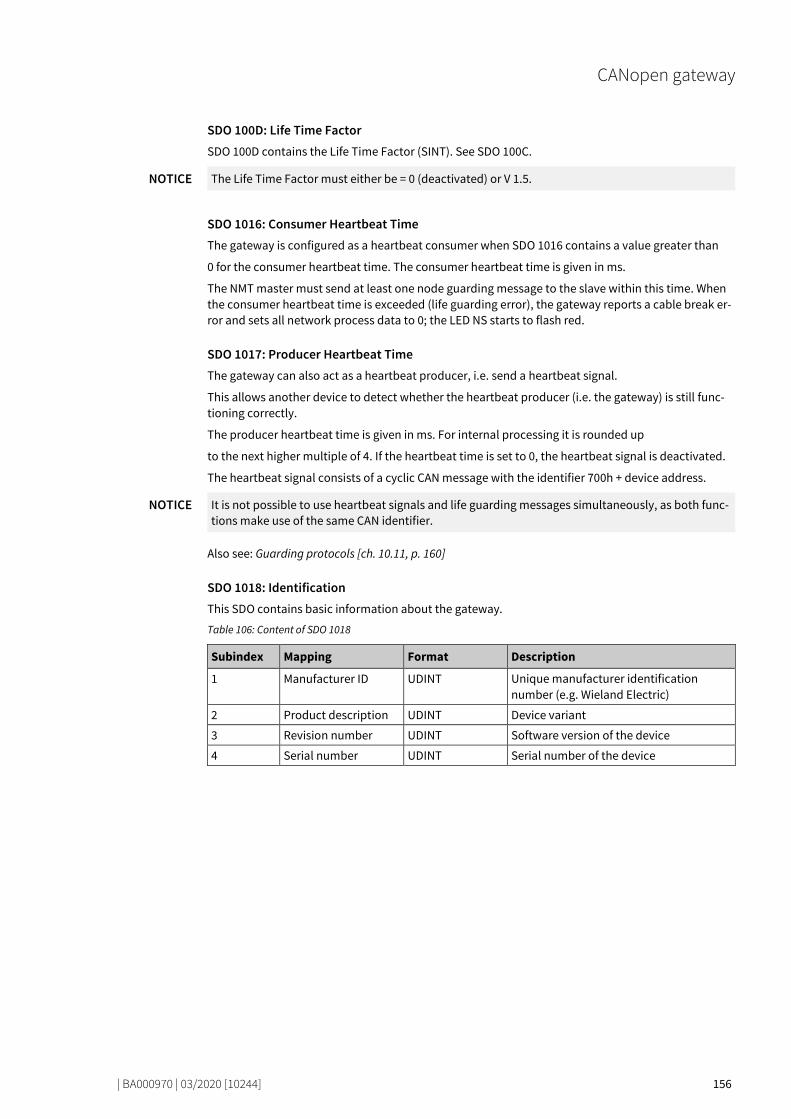
CANopen gateway
| BA000970 | 03/2020 [10244] 156
SDO 100D: Life Time Factor SDO 100D contains the Life Time Factor (SINT). See SDO 100C.
NOTICE The Life Time Factor must either be = 0 (deactivated) or V 1.5.
SDO 1016: Consumer Heartbeat Time The gateway is configured as a heartbeat consumer when SDO 1016 contains a value greater than
0 for the consumer heartbeat time. The consumer heartbeat time is given in ms.
The NMT master must send at least one node guarding message to the slave within this time. When the consumer heartbeat time is exceeded (life guarding error), the gateway reports a cable break er-ror and sets all network process data to 0; the LED NS starts to flash red.
SDO 1017: Producer Heartbeat Time The gateway can also act as a heartbeat producer, i.e. send a heartbeat signal.
This allows another device to detect whether the heartbeat producer (i.e. the gateway) is still func-tioning correctly.
The producer heartbeat time is given in ms. For internal processing it is rounded up
to the next higher multiple of 4. If the heartbeat time is set to 0, the heartbeat signal is deactivated.
The heartbeat signal consists of a cyclic CAN message with the identifier 700h + device address.
NOTICE It is not possible to use heartbeat signals and life guarding messages simultaneously, as both func-tions make use of the same CAN identifier.
Also see: Guarding protocols [ch. 10.11, p. 160]
SDO 1018: Identification This SDO contains basic information about the gateway.
Table 106: Content of SDO 1018
Subindex Mapping Format Description
1 Manufacturer ID UDINT Unique manufacturer identification number (e.g. Wieland Electric)
2 Product description UDINT Device variant
3 Revision number UDINT Software version of the device
4 Serial number UDINT Serial number of the device
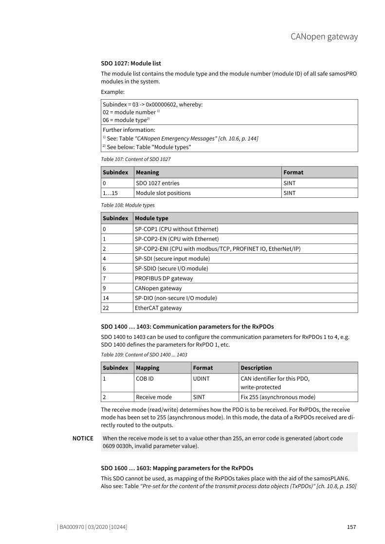
CANopen gateway
| BA000970 | 03/2020 [10244] 157
SDO 1027: Module list The module list contains the module type and the module number (module ID) of all safe samosPRO modules in the system.
Example:
Subindex = 03 -> 0x00000602, whereby: 02 = module number 1) 06 = module type2)
Further information: 1) See: Table "CANopen Emergency Messages" [ch. 10.6, p. 144] 2) See below: Table "Module types"
Table 107: Content of SDO 1027
Subindex Meaning Format
0 SDO 1027 entries SINT
1…15 Module slot positions SINT
Table 108: Module types
Subindex Module type
0 SP-COP1 (CPU without Ethernet)
1 SP-COP2-EN (CPU with Ethernet)
2 SP-COP2-ENI (CPU with modbus/TCP, PROFINET IO, EtherNet/IP)
4 SP-SDI (secure input module)
6 SP-SDIO (secure I/O module)
7 PROFIBUS DP gateway
9 CANopen gateway
14 SP-DIO (non-secure I/O module)
22 EtherCAT gateway
SDO 1400 … 1403: Communication parameters for the RxPDOs SDO 1400 to 1403 can be used to configure the communication parameters for RxPDOs 1 to 4, e.g. SDO 1400 defines the parameters for RxPDO 1, etc.
Table 109: Content of SDO 1400 ... 1403
Subindex Mapping Format Description
1 COB ID UDINT CAN identifier for this PDO, write-protected
2 Receive mode SINT Fix 255 (asynchronous mode)
The receive mode (read/write) determines how the PDO is to be received. For RxPDOs, the receive mode has been set to 255 (asynchronous mode). In this mode, the data of a RxPDOs received are di-rectly routed to the outputs.
NOTICE When the receive mode is set to a value other than 255, an error code is generated (abort code 0609 0030h, invalid parameter value).
SDO 1600 … 1603: Mapping parameters for the RxPDOs This SDO cannot be used, as mapping of the RxPDOs takes place with the aid of the samosPLAN 6. Also see: Table "Pre-set for the content of the transmit process data objects (TxPDOs)" [ch. 10.8, p. 150]
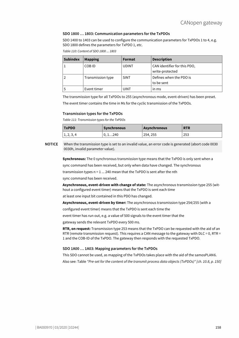
CANopen gateway
| BA000970 | 03/2020 [10244] 158
SDO 1800 … 1803: Communication parameters for the TxPDOs SDO 1400 to 1403 can be used to configure the communication parameters for TxPDOs 1 to 4, e.g. SDO 1800 defines the parameters for TxPDO 1, etc.
Table 110: Content of SDO 1800 ... 1803
Subindex Mapping Format Description
1 COB ID UDINT CAN identifier for this PDO, write-protected
2 Transmission type SINT Defines when the PDO is to be sent
5 Event timer UINT in ms
The transmission type for all TxPDOs to 255 (asynchronous mode, event-driven) has been preset.
The event timer contains the time in Ms for the cyclic transmission of the TxPDOs.
Transmission types for the TxPDOs Table 111: Transmission types for the TxPDOs
TxPDO Synchronous Asynchronous RTR
1, 2, 3, 4 0, 1…240 254, 255 253
NOTICE When the transmission type is set to an invalid value, an error code is generated (abort code 0030 0030h, invalid parameter value).
Synchronous: The 0 synchronous transmission type means that the TxPDO is only sent when a
sync command has been received, but only when data have changed. The synchronous
transmission types n = 1 ... 240 mean that the TxPDO is sent after the nth
sync command has been received.
Asynchronous, event-driven with change of state: The asynchronous transmission type 255 (wit-hout a configured event timer) means that the TxPDO is sent each time
at least one input bit contained in this PDO has changed.
Asynchronous, event-driven by timer: The asynchronous transmission type 254/255 (with a
configured event timer) means that the TxPDO is sent each time the
event timer has run out, e.g. a value of 500 signals to the event timer that the
gateway sends the relevant TxPDO every 500 ms.
RTR, on request: Transmission type 253 means that the TxPDO can be requested with the aid of an RTR (remote transmission request). This requires a CAN message to the gateway with DLC = 0, RTR = 1 and the COB-ID of the TxPDO. The gateway then responds with the requested TxPDO.
SDO 1A00 … 1A03: Mapping parameters for the TxPDOs This SDO cannot be used, as mapping of the TxPDOs takes place with the aid of the samosPLAN 6.
Also see: Table "Pre-set for the content of the transmit process data objects (TxPDOs)" [ch. 10.8, p. 150]

CANopen gateway
| BA000970 | 03/2020 [10244] 159
SDO 3100: Module state bits SDO 3100 contains the module state bits of the samosPRO system (see Table "CANopen Emergency Messages" [ch. 10.6, p. 144]). Active bits are low (= "0").
Table 112: Content of SDO 3100
SDO array Data set parameters Module Size
3100.1-3 Status of Module 0 Controller module
UDINT
3100.4 Status of Module 1 Expansion UDINT
… … … …
3100.14 Status of Module 11 Expansion UDINT
3100.15 Status of Module 12 Expansion UDINT
NOTICE The positions of the modules are numbered in the samosPLAN 6 from 0 to 14. Thus the sub-index for SDO 3100 = Position + 3, with the first three sub-indices for the SP-COPx module being used.
SDO 3100 can only be read.
SDO 3200: Config-CRC SDO 3200 contains the system CRCs in UDINT format.
SDO 6000: Process data input objects The 32 bytes of the process input data can be written into SDO array 6000. These are the same data as in RxPDO 1-4 (see PDO Communication [ch. 10.8, p. 150]). The mapping is as follows:
Table 113: Mapping table for SDO 6000 – RxPDO 1-4
SDO 6000 RxPDO
6000.1 RxPDO 1, Byte 1
… …
6000.8 RxPDO 1, Byte 8
6000.9-16 RxPDO 2, Byte 1-8
6000.17-24 RxPDO 3, Byte 1-8
6000.25-32 RxPDO 4, Byte 1-8
SDO 6000 can only be written.
SDO 6200: Process data output objects The 32 bytes of the process output data can be written into SDO array 6200. These are the same data as in TxPDO 1-4 (see PDO Communication [ch. 10.8, p. 150]). The mapping is as follows:
Table 114: Mapping table for SDO 6200 – TxPDO 1-4
SDO 6200 TxPDO
6200.1 TxPDO 1, Byte 1
… …
6200.8 TxPDO 1, Byte 8
6200.9-16 TxPDO 2, Byte 1-8
6200.17-24 TxPDO 3, Byte 1-8
6200.25-32 TxPDO 4, Byte 1-8
SDO 6200 can only be read.
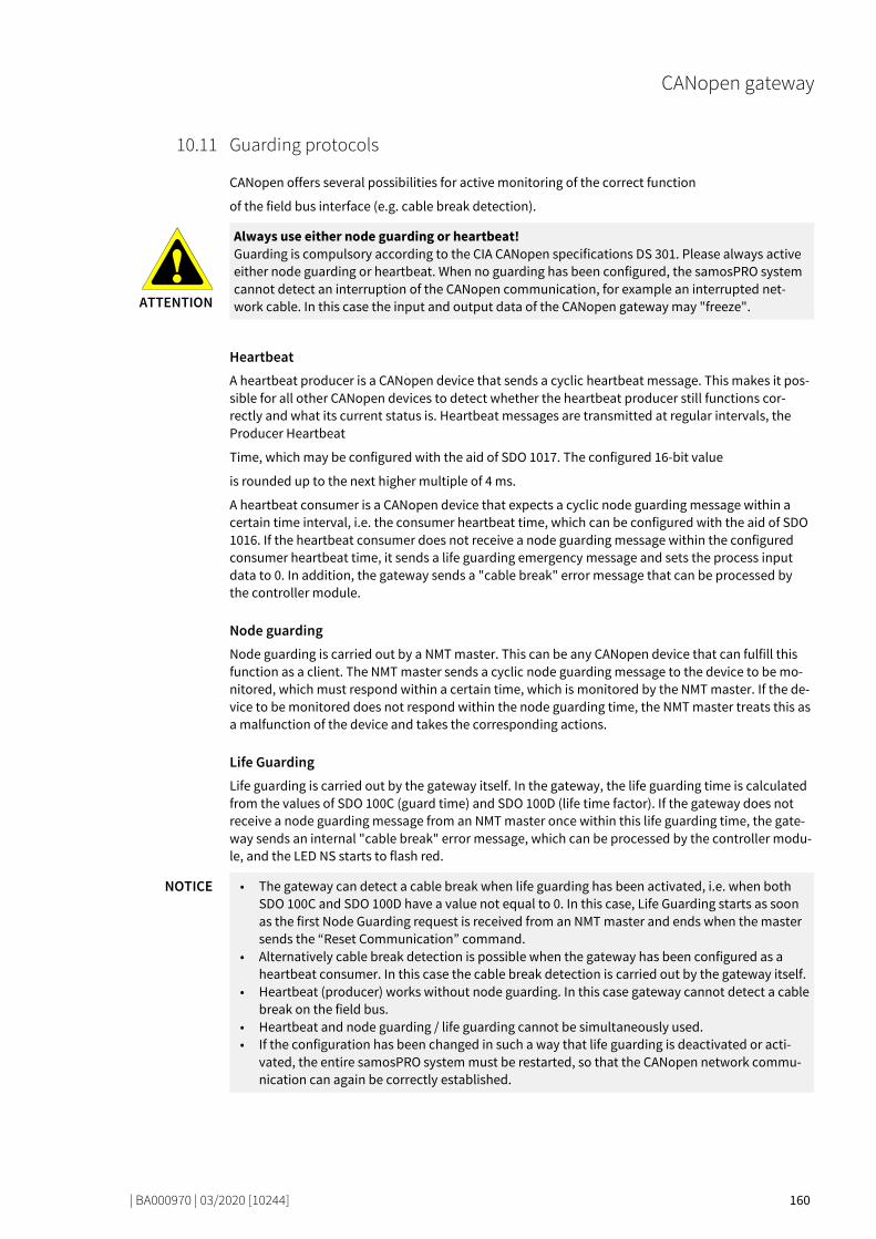
CANopen gateway
| BA000970 | 03/2020 [10244] 160
Guarding protocols 78725643
CANopen offers several possibilities for active monitoring of the correct function
of the field bus interface (e.g. cable break detection).
ATTENTION
Always use either node guarding or heartbeat! Guarding is compulsory according to the CIA CANopen specifications DS 301. Please always active either node guarding or heartbeat. When no guarding has been configured, the samosPRO system cannot detect an interruption of the CANopen communication, for example an interrupted net-work cable. In this case the input and output data of the CANopen gateway may "freeze".
Heartbeat A heartbeat producer is a CANopen device that sends a cyclic heartbeat message. This makes it pos-sible for all other CANopen devices to detect whether the heartbeat producer still functions cor-rectly and what its current status is. Heartbeat messages are transmitted at regular intervals, the Producer Heartbeat
Time, which may be configured with the aid of SDO 1017. The configured 16-bit value
is rounded up to the next higher multiple of 4 ms.
A heartbeat consumer is a CANopen device that expects a cyclic node guarding message within a certain time interval, i.e. the consumer heartbeat time, which can be configured with the aid of SDO 1016. If the heartbeat consumer does not receive a node guarding message within the configured consumer heartbeat time, it sends a life guarding emergency message and sets the process input data to 0. In addition, the gateway sends a "cable break" error message that can be processed by the controller module.
Node guarding Node guarding is carried out by a NMT master. This can be any CANopen device that can fulfill this function as a client. The NMT master sends a cyclic node guarding message to the device to be mo-nitored, which must respond within a certain time, which is monitored by the NMT master. If the de-vice to be monitored does not respond within the node guarding time, the NMT master treats this as a malfunction of the device and takes the corresponding actions.
Life Guarding Life guarding is carried out by the gateway itself. In the gateway, the life guarding time is calculated from the values of SDO 100C (guard time) and SDO 100D (life time factor). If the gateway does not receive a node guarding message from an NMT master once within this life guarding time, the gate-way sends an internal "cable break" error message, which can be processed by the controller modu-le, and the LED NS starts to flash red.
NOTICE • The gateway can detect a cable break when life guarding has been activated, i.e. when both SDO 100C and SDO 100D have a value not equal to 0. In this case, Life Guarding starts as soon as the first Node Guarding request is received from an NMT master and ends when the master sends the “Reset Communication” command.
• Alternatively cable break detection is possible when the gateway has been configured as a heartbeat consumer. In this case the cable break detection is carried out by the gateway itself.
• Heartbeat (producer) works without node guarding. In this case gateway cannot detect a cable break on the field bus.
• Heartbeat and node guarding / life guarding cannot be simultaneously used. • If the configuration has been changed in such a way that life guarding is deactivated or acti-
vated, the entire samosPRO system must be restarted, so that the CANopen network commu-nication can again be correctly established.
10.11

CANopen gateway
| BA000970 | 03/2020 [10244] 161
The following table provides an overview of the supported guarding protocols, depending on the configuration of SDO 1016 and SDO 1017 (heartbeat), SDO 100C (guard time) and SDO 100D (life time factor).
Table 115: Overview and comparison of the guarding protocols
SDO 1016
SDO 1017
SDO 100C × 100D
Heartbeat gateway Life Guarding Gateway
Node guarding NMT master
0 0 0 Not permitted: Always make use of either node guarding or heartbeat!
0 0 > 0 Deactivated Cable break detec-tion
Required
> 0 0 0 Cyclic heartbeat (consumer)
Cable break detec-tion
Possible for other slaves
0 > 0 0 Cyclic heartbeat (producer)
Not possible Not possible, but guarding as a heartbeat consumer is possible
> 0 > 0 0 Cyclic heartbeat (producer und consumer)
Cable break detec-tion
Not possible
> 0 > 0 > 0 Not permitted
NOTICE It does not make sense to use heartbeat and life guarding simultaneously.
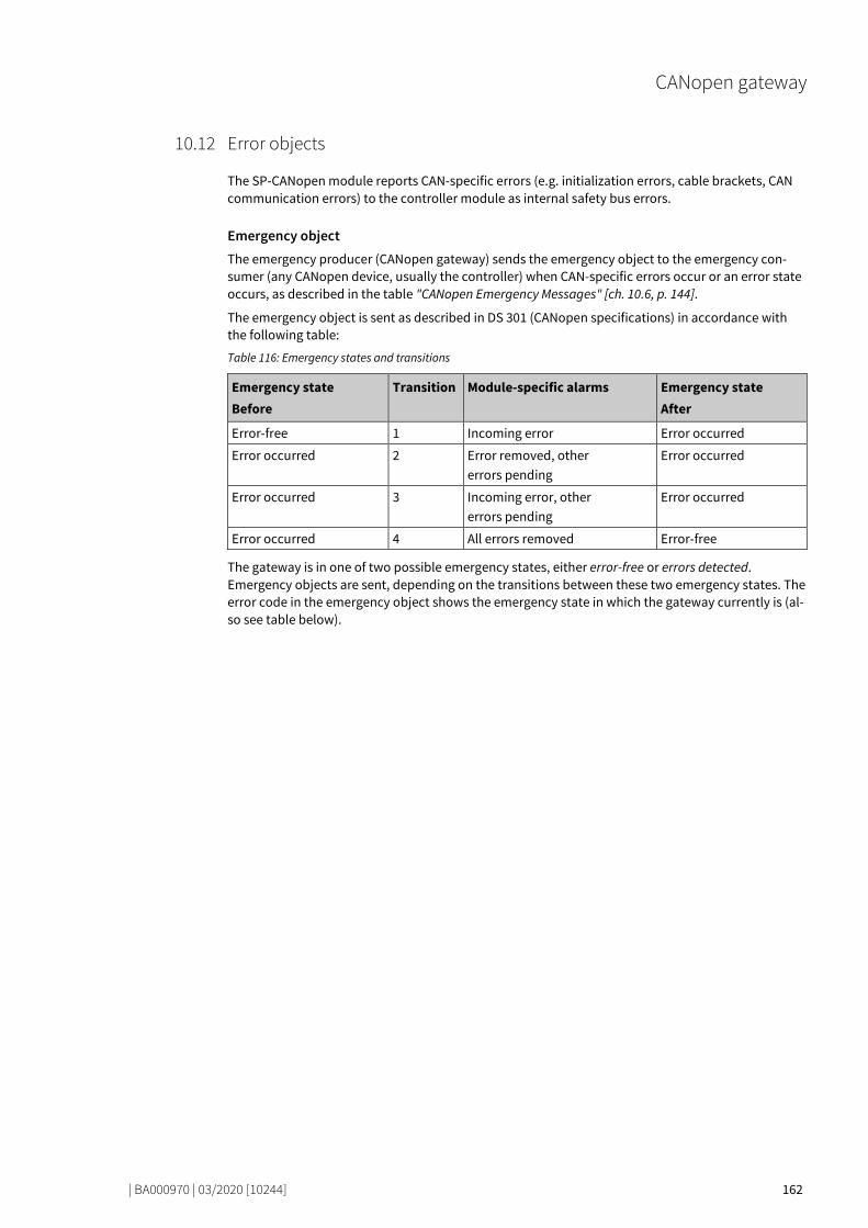
CANopen gateway
| BA000970 | 03/2020 [10244] 162
Error objects 78738187
The SP-CANopen module reports CAN-specific errors (e.g. initialization errors, cable brackets, CAN communication errors) to the controller module as internal safety bus errors.
Emergency object The emergency producer (CANopen gateway) sends the emergency object to the emergency con-sumer (any CANopen device, usually the controller) when CAN-specific errors occur or an error state occurs, as described in the table "CANopen Emergency Messages" [ch. 10.6, p. 144].
The emergency object is sent as described in DS 301 (CANopen specifications) in accordance with the following table:
Table 116: Emergency states and transitions
Emergency state Before
Transition Module-specific alarms Emergency state After
Error-free 1 Incoming error Error occurred
Error occurred 2 Error removed, other errors pending
Error occurred
Error occurred 3 Incoming error, other errors pending
Error occurred
Error occurred 4 All errors removed Error-free
The gateway is in one of two possible emergency states, either error-free or errors detected. Emergency objects are sent, depending on the transitions between these two emergency states. The error code in the emergency object shows the emergency state in which the gateway currently is (al-so see table below).
10.12
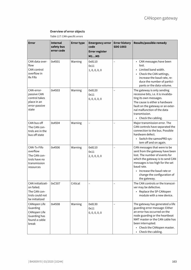
CANopen gateway
| BA000970 | 03/2020 [10244] 163
Overview of error objects Table 117: CAN-specific errors
Error Internal safety bus error code
Error type Emergency error code Error register M1…M5
Error history SDO 1003
Results/possible remedy
CAN data over-flow CAN control overflow in Rx Fifo
0x4501 Warning 0x8110 0x11 1, 0, 0, 0, 0
– • CAN messages have been lost.
• Limited band width. • Check the CAN settings,
increase the baud rate, re-duce the number of partici-pants or the data volume.
CAN-error-passive CAN control takes place in an error-passive state
0x4503 Warning 0x8120 0x11 0, 0, 0, 0, 0
– The gateway is only sending recessive bits, i.e. it is invalida-ting its own messages. The cause is either a hardware fault on the gateway or an exter-nal malfunction of the data transmission. • Check the cabling.
CAN bus off The CAN con-trols are in the bus off state
0x4504 Warning – – Major transmission error. The CAN controls have separated the connection to the bus. Possible hardware defect. • Switch the samosPRO sys-
tem off and on again.
CAN-Tx-Fifo overflow The CAN con-trols have no transmission resources
0x4506 Warning 0x8110 0x11 2, 0, 0, 0, 0
– CAN messages that were to be sent from the gateway have been lost. The number of events for which the gateway is to send CAN messages is too high for the set baud rate. • Increase the baud rate or
change the configuration of the gateway.
CAN initializati-on failed. The CAN con-trols could not be initialized
0xC507 Critical – – The CAN controls or the transcei-ver may be defective. • Replace the SP-CANopen
module with a new device.
CANopen Life Guarding CANopen Life Guarding has found a cable break
0x4508 Warning 0x8130 0x11 0, 0, 0, 0, 0
– The gateway has generated a life guarding error message: Either an error has occurred on the node guarding or the heartbeat NMT master or the CAN cable has been interrupted. • Check the CANopen master. • Check the cabling.
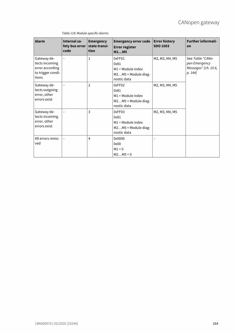
CANopen gateway
| BA000970 | 03/2020 [10244] 164
Table 118: Module-specific alarms
Alarm Internal sa-fety bus error code
Emergency state transi-tion
Emergency error code Error register M1…M5
Error history SDO 1003
Further informati-on
Gateway de-tects incoming error according to trigger condi-tions
– 1 0xFF01 0x81 M1 = Module index M2…M5 = Module diag-nostic data
M2, M3, M4, M5 See Table "CANo-pen Emergency Messages" [ch. 10.6, p. 144]
Gateway de-tects outgoing error, other errors exist
– 2 0xFF02 0x81 M1 = Module index M2…M5 = Module diag-nostic data
M2, M3, M4, M5
Gateway de-tects incoming error, other errors exist
– 3 0xFF03 0x81 M1 = Module index M2…M5 = Module diag-nostic data
M2, M3, M4, M5
All errors remo-ved
– 4 0x0000 0x00 M1 = 0 M2…M5 = 0
–

CANopen gateway
| BA000970 | 03/2020 [10244] 165
CANopen diagnostic examples 78773259
Example 1: Secure IO module in position 1, output Q4 has a short-circuit to high The gateway sends am Emergency message (see Table "CANopen Emergency Messages [ch. 10.6, p. 144]").
CAN-ID DLC DATA
08C 8 03 FF 01 03 40 00 00 00
The CANopen address of the gateway is 12 (= C Hex). The secure IO module has position 1 in the sa-mosPRO system.
08C: Identifier (80 + C) 8: Data length code: This is followed by 8 bytes 03FF: Error code FF03: Device-specific error 01: Error register 01 of SDO 1001H 03: Module index M1: Module in position 1 40: Module state bit 30 (bit 6 of byte M2) = 1: Short-circuit to high at output 4 (see Table
"CANopen Emergency Messages" [ch. 10.6, p. 144])
Reading the current error from SDO 3100: PLC requests:
CAN-ID DLC DATA
60C 8 40 00 31 04 00 00 00 00
60C: Identifier (600 + C) 8: Data length code: This is followed by 8 bytes 40: Expedited upload requirement 00 31: Index 3100 04: Subindex: Module to Position 1
(see table "Content of SDO 3100" [ch. 10.10, p. 159])
Gateway response:
CAN-ID DLC DATA
58C 8 42 00 31 04 BF FF FF FB
58C: Identifier (580 + C) 8: Data length code: This is followed by 8 bytes 42: Upload response, size of data set is not shown 00 31: Index 3100 04: Subindex: Module to Position 1
(see table "Content of SDO 3100" [ch. 10.10, p. 159]) FB: Error byte M5, Bit 2 = 0: external error BF: Error byte M2, Bit 30 = 0. Error: Short-circuit after high at output 4
10.13

CANopen gateway
| BA000970 | 03/2020 [10244] 166
Reading of error from the error history in SDO 1003: PLC requests:
CAN-ID DLC DATA
60C 8 40 03 10 01 00 00 00 00
60C: Identifier (600 + C) 8: Data length code: This is followed by 8 bytes 40: Expedited upload requirement 03 10: Index 1003 01: Sub-index: last error
Gateway response:
CAN-ID DLC DATA
58C 8 42 03 10 01 40 00 00 00
58C: Identifier (580 + C) 8: Data length code: This is followed by 8 bytes 42: Upload response, size of data set is not shown 03 10: Index 1003 01: Sub-index: last error 40: Module state bit 30 (bit 6 of byte M2) = 0: Short-circuit after high at output 4
Example 2: Secure I/O module with error at two-channel input I1/I2 The gateway sends am Emergency message (see Table “Emergency Messages [ch. 10.6, p. 144]").
CAN-ID DLC DATA
08C 8 03 FF 01 0E 00 00 01 00
The CANopen address of the gateway is 12 (= C Hex). The SP-SDI module has position 12 in the sa-mosPRO system.
08C: Identifier (80 + C) 8: Data length code: This is followed by 8 bytes. 03FF: Error code FF03: Device-specific error 01: Error register 01 of SDO 1001H 0E: Module index M1: Module in position 12 (E Hex) 01: Module status bit 8 (bit 0 of byte M4) = 1: two-channel evaluation of inputs 1–2: Error
detected (see Table "CANopen Emergency Messages" [ch. 10.6, p. 144])

CANopen gateway
| BA000970 | 03/2020 [10244] 167
Reading the current error from SDO 3100: PLC requests:
CAN-ID DLC DATA
60C 8 40 00 31 0F 00 00 00 00
60C: Identifier (600 + C) 8: Data length code: This is followed by 8 bytes 40: Expedited upload requirement 00 31: Index 3100 0F: Subindex 0F = Module to position 12 (module position = subindex - 1
(see also table "Content of SDO 3100" [ch. 10.10, p. 159])
Gateway response:
CAN-ID DLC DATA
58C 8 42 00 31 0F FF FF FE FB
58C: Identifier (580 + C) 8: Data length code: This is followed by 8 bytes 42: Upload response, size of data set is not shown 00 31: Index 3100 04: Subindex: Module to Position 1
(see table "Content of SDO 3100" [ch. 10.10, p. 159]) FB: Error byte M5, Bit 2 = 0: external error FE: Error byte M4, bit 0 = 0: two-channel evaluation of inputs 1–2: Error detected
(See Table "CANopen Emergency Messages" [ch. 10.6, p. 144])
Reading of error from the error history in SDO 1003: PLC requests:
CAN-ID DLC DATA
60C 8 40 03 10 01 00 00 00 00
60C: Identifier (600 + C) 8: Data length code: This is followed by 8 bytes 40: Expedited upload requirement 03 10: Index 1003 01: Sub-index: last error

CANopen gateway
| BA000970 | 03/2020 [10244] 168
Gateway response:
CAN-ID DLC DATA
58C 8 42 03 10 01 00 00 01 00
58C: Identifier (580 + C) 8: Data length code: This is followed by 8 bytes 42: Upload response, size of data set is not shown 03 10: Index 1003 01: Sub-index: last error 01: Module status bit 8 (bit 0 of byte M4) = 0: two-channel evaluation of inputs 1–2: error
detected
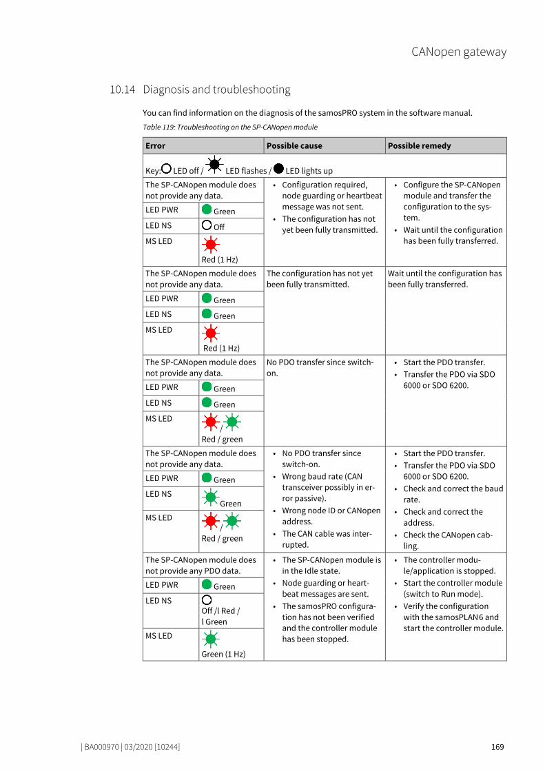
CANopen gateway
| BA000970 | 03/2020 [10244] 169
Diagnosis and troubleshooting 78799627
You can find information on the diagnosis of the samosPRO system in the software manual.
Table 119: Troubleshooting on the SP-CANopen module
Error Possible cause Possible remedy
Key: LED off / LED flashes / LED lights up
The SP-CANopen module does not provide any data.
• Configuration required, node guarding or heartbeat message was not sent.
• The configuration has not yet been fully transmitted.
• Configure the SP-CANopen module and transfer the configuration to the sys-tem.
• Wait until the configuration has been fully transferred.
LED PWR Green
LED NS Off
MS LED
Red (1 Hz)
The SP-CANopen module does not provide any data.
The configuration has not yet been fully transmitted.
Wait until the configuration has been fully transferred.
LED PWR Green
LED NS Green
MS LED
Red (1 Hz)
The SP-CANopen module does not provide any data.
No PDO transfer since switch-on.
• Start the PDO transfer. • Transfer the PDO via SDO
6000 or SDO 6200. LED PWR Green
LED NS Green
MS LED /
Red / green
The SP-CANopen module does not provide any data.
• No PDO transfer since switch-on.
• Wrong baud rate (CAN transceiver possibly in er-ror passive).
• Wrong node ID or CANopen address.
• The CAN cable was inter-rupted.
• Start the PDO transfer. • Transfer the PDO via SDO
6000 or SDO 6200. • Check and correct the baud
rate. • Check and correct the
address. • Check the CANopen cab-
ling.
LED PWR Green
LED NS Green
MS LED /
Red / green
The SP-CANopen module does not provide any PDO data.
• The SP-CANopen module is in the Idle state.
• Node guarding or heart-beat messages are sent.
• The samosPRO configura-tion has not been verified and the controller module has been stopped.
• The controller modu-le/application is stopped.
• Start the controller module (switch to Run mode).
• Verify the configuration with the samosPLAN 6 and start the controller module.
LED PWR Green
LED NS Off /l Red / l Green
MS LED
Green (1 Hz)
10.14
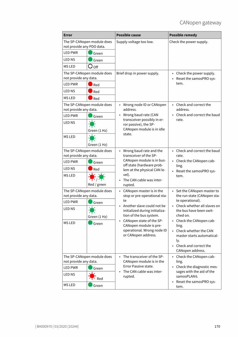
CANopen gateway
| BA000970 | 03/2020 [10244] 170
Error Possible cause Possible remedy
The SP-CANopen module does not provide any PDO data.
Supply voltage too low. Check the power supply.
LED PWR Green
LED NS Green
MS LED Off
The SP-CANopen module does not provide any data.
Brief drop in power supply. • Check the power supply. • Reset the samosPRO sys-
tem. LED PWR Red
LED NS Red
MS LED Red
The SP-CANopen module does not provide any data.
• Wrong node ID or CANopen address.
• Wrong baud rate (CAN transceiver possibly in er-ror passive), the SP-CANopen module is in idle state.
• Check and correct the address.
• Check and correct the baud rate.
LED PWR Green
LED NS
Green (1 Hz)
MS LED
Green (1 Hz)
The SP-CANopen module does not provide any data.
• Wrong baud rate and the transceiver of the SP-CANopen module is in bus-off state (hardware prob-lem at the physical CAN le-vel).
• The CAN cable was inter-rupted.
• Check and correct the baud rate.
• Check the CANopen cab-ling.
• Reset the samosPRO sys-tem.
LED PWR Green
LED NS Red
MS LED /
Red / green
The SP-CANopen module does not provide any data.
• CANopen master is in the stop or pre-operational sta-te
• Another slave could not be initialized during initializa-tion of the bus system.
• CANopen state of the SP-CANopen module is pre-operational. Wrong node ID or CANopen address.
• Set the CANopen master to the run state (CANopen sta-te operational).
• Check whether all slaves on the bus have been swit-ched on.
• Check the CANopen cab-ling.
• Check whether the CAN master starts automatical-ly.
• Check and correct the CANopen address.
LED PWR Green
LED NS
Green (1 Hz)
MS LED Green
The SP-CANopen module does not provide any data.
• The transceiver of the SP-CANopen module is in the Error Passive state.
• The CAN cable was inter-rupted.
• Check the CANopen cab-ling.
• Check the diagnostic mes-sages with the aid of the samosPLAN 6.
• Reset the samosPRO sys-tem.
LED PWR Green
LED NS Red
MS LED Green

CANopen gateway
| BA000970 | 03/2020 [10244] 171
Error Possible cause Possible remedy
The SP-CANopen module does not provide any data.
• Node guarding or heart-beat consumer failure
• The guarding configuration was changed.
• Check the CANopen cab-ling.
• Check the life guarding time (life time factor V 1).
• Check the heartbeat con-sumer time (should be V 1.5 × heartbeat producer time).
• Check the diagnostic mes-sages with the aid of the samosPLAN 6.
• Reset the samosPRO sys-tem.
LED PWR Green
LED NS
Red (1 Hz)
MS LED /
Red / green
The SP-CANopen module is in the critical error state
• Internal equipment error on the SP-CANopen modu-le.
• The module version of the controller module does not support samosPRO gate-ways.
• Switch the samosPRO system’s power supply off and on again.
• Check the diagnostic mes-sages with the aid of the samosPLAN 6.
• Use the controller module with the required module version.
• If the error persists, replace the gateway.
LED PWR Green
LED NS Red
MS LED
Red (2 Hz)
The SP-CANopen / the sa-mosPRO system is in the Criti-cal error state.
• The SP-CANopen module is not properly connected to the samosPRO modules.
• The module connection plug is dirty or damaged.
• Another samosPRO module has an internal critical er-ror.
• Plug the SP-CANopen mo-dule in correctly.
• Clean the connection plug and socket.
• Switch on the power supp-ly
• once again. • Check the other samosPRO
modules.
LED PWR Red
LED NS Off
MS LED Red
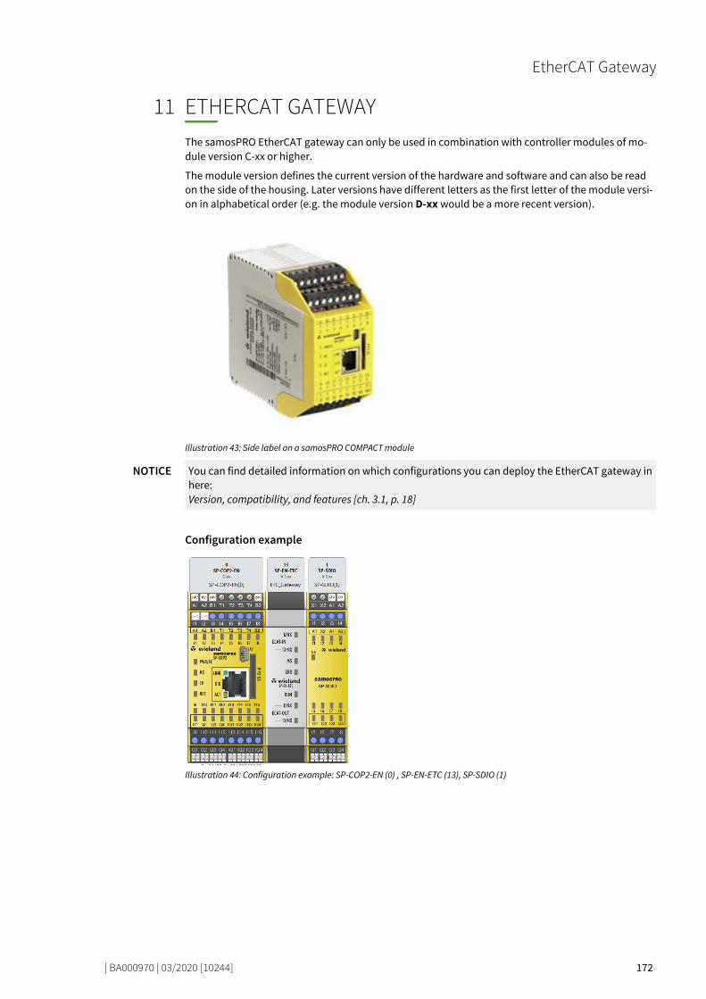
EtherCAT Gateway
| BA000970 | 03/2020 [10244] 172
ETHERCAT GATEWAY
79351307
The samosPRO EtherCAT gateway can only be used in combination with controller modules of mo-dule version C-xx or higher.
The module version defines the current version of the hardware and software and can also be read on the side of the housing. Later versions have different letters as the first letter of the module versi-on in alphabetical order (e.g. the module version D-xx would be a more recent version).
Illustration 43: Side label on a samosPRO COMPACT module
NOTICE You can find detailed information on which configurations you can deploy the EtherCAT gateway in here: Version, compatibility, and features [ch. 3.1, p. 18]
Configuration example
Illustration 44: Configuration example: SP-COP2-EN (0) , SP-EN-ETC (13), SP-SDIO (1)
11

EtherCAT Gateway
| BA000970 | 03/2020 [10244] 173
Interfaces and operation 79373835
Operation and display elements
Illustration 45: Operating and display elements of the SP-EN-ETC module
Table 120: Meaning of the state LEDs on the SP-EN-ETC module
LED Meaning
Key: LED off / LED flashes / LED lights up
ECAT-IN
LINK
Off No EtherCAT device connected, no connection.
Green EtherCAT device connected.
Green Communication with connected EtherCAT device
TX/RX Off Not used
MS
Off No voltage supply / No connection to the head-end station
Green On: samosPRO system in operation.
Green Flashing 1 Hz: samosPRO system stopped
/ Red / green
Alternate flashing: Run but the gateway has an error (e.g. no EtherCAT connection)
Red Flashing 1 Hz: Configuration required or is taking place right now
Red On: Critical errors
11.1

EtherCAT Gateway
| BA000970 | 03/2020 [10244] 174
LED Meaning
ERR Off No error: The EtherCAT communication of the device is in operation
Red Double flash Application watchdog timeout: An application watchdog time-out occurred (Example: Sync Manager watchdog timeout)
Red Single flash Unrequested status change: The slave device application has autonomously changed the EtherCAT status: The "Change" parameter in the ALStatus register is 0x01:change/error.
Red Blink Invalid configuration: General configuration error (Example: The configuration has not yet been fully transmitted.)
Red On Watchdog timeout: A watchdog timeout has occurred. (Example: The application controller is no longer responding )
RUN Off Off "INIT": The device is in the INIT state.
Green On "OPERATIONAL"
Green Blink "PRE-OPERATIONAL"
Green Single flash "SAFE-OPERATIONAL"
ECAT-OUT
LINK Off No EtherCAT device connected, no connection
Green On EtherCAT device is connected
Green Blink The device sends/receives Ethernet frames
TX/RX Off This LED is not used
Table 121: Information about the light behavior of the EtherCAT status LEDs
LED states Description
On The indicator is constantly on.
Off The indicator does not come on.
Blink The indicator is switched on or off in phases at a frequency of 2.5 Hz.
Single flash
The indicator shows one short flash (200 ms) followed by a longer off phase (1000 ms).
Double flash The indicator shows a sequence of two short flashes (200 ms each) inter-rupted by a short off phase (200 ms). The sequence is finished by a long off phase (1000 ms).

EtherCAT Gateway
| BA000970 | 03/2020 [10244] 175
EtherCAT basics 79493259
General information Field buses have been established in automation engineering for many years. Since on the one hand there is demand for ever higher speeds, but on the other hand the technical limits have already been reached with this technology, new solutions must be sought.
The Ethernet known from the office world, with its available-everywhere 100Mbit/s, is very fast. The type of cabling used there and the rules governing access rights mean that this Ethernet is not real-time capable. This effect has been rectified with EtherCAT.
EtherCAT For EtherCAT: EtherCAT is a registered trademark and patented technology, licensed by Beckhoff Automation GmbH, Germany.
EtherCAT stands for Ethernet for Controller and Automation Technology. It was originally developed by Beckhoff Automation GmbH and is now supported and further developed by the EtherCAT Tech-nology Group (ETG). The ETG is the world's largest international users and manufacturers associati-on for industrial Ethernet with around 1450 member firms (as at October 2010).
EtherCAT is an open Ethernet-based fieldbus system that is standardized in the IEC. As an open fiel-dbus system, EtherCAT satisfies the user profile for the area of industrial real-time systems.
Unlike traditional Ethernet communications, in EtherCAT the I/O data are exchanged at 100MBit/s in full duplex mode, while the telegram passes through the coupler. Since in this way a telegram reaches lots of devices in the transmit and receive direction, EtherCAT has a useful data rate of over 90%.
The EtherCAT protocol, optimized for process data, is transported directly in the Ethernet telegram. In turn, this can consists of several sub-telegrams, each serving one memory area of the process image.
Transmission medium EtherCAT uses Ethernet as the transmission medium. Standard CAT5 cable is used. Cable lengths of up to 100m between 2 devices are possible.
Only EtherCAT components may be used in an EtherCAT network. To implement topologies devia-ting from the linear structure corresponding EtherCAT components are required that support this. It is not possible to use hubs.
Communication principle In EtherCAT the master sends a telegram to the first device. This extracts the data intended for it from the data flow, inserts its response data into the telegram and sends the telegram on to the next device. The next device processes the telegram in the same way.
If the telegram has reached the last device, this recognizes that no more devices are connected and sends the telegram back to the master. In this way the telegram is sent via the other pair of wires through all devices to the master (full duplex). The connection sequence and the use of full-duplex technology means EtherCAT is a logical ring.
11.2

EtherCAT Gateway
| BA000970 | 03/2020 [10244] 176
DA SA Type Data CRC
HeaderEtherCAT Frame
Datagramm Slave 01 Datagramm Slave n...
Command HeaderEtherCAT Datagramm
Data Working Counter
Mailbox HeaderEtherCAT Datagramm
Mailbox Service Data
CANopen HeaderType = CoE (CANopen over EtherCAT)
CANopen Data
NumberCoE Header
Reserved Service
0: reserved1: Emergency message2: SDO request3: SDO response4: TxPDO
5: RxPDO6: Remote request of TxPDO7: Remote request of RxPDO8: SDO information9...15: reserved
Service
Ethernet Frame
DA Destination address SA Source address
CRC Checksum Type Ether type (example: the entry 0x88A4 means Ether-CAT protocol.)
Components The components of the CoE interface are listed below:
EtherCAT State Machine The EtherCAT State Machine controls the state of the EtherCAT coupler.
Object directory The object directory lists all parameter, diagnostic, process or other data which can be read or described via EtherCAT. The SDO information service provides access to the object directory.
Process data The EtherCAT data link layer is optimized for the fast transfer of process data. This determines how the process data of the device is assigned to the EtherCAT process data and how the application on the device is synchronized to the EtherCAT cycle.
The assignment of the process data (mapping) is done via the PDO Mapping and the SyncManager PDO Assign objects. These describe which objects from the object directory are transferred as pro-cess data with EtherCAT. The SyncManager Communication objects determine the cycle time with which the associated process data are transferred via EtherCAT and in what form it is synchronized for transmission.
ESI file: Wieland SP EN ETC V1.2.xml You will receive an ESI file from Wieland for the EtherCAT gateway. This file is located either on the enclosed disk or in the download area of http://www.wielandinc.com/. Install the ESI files in your PLC software configuration tool. Further details on installation of the ESI files can be found in the PLC manual.

EtherCAT Gateway
| BA000970 | 03/2020 [10244] 177
EtherCAT state machine 79532427
States A state machine is implemented in every EtherCAT coupler. For each state it is defined which com-munication services are active via EtherCAT. EtherCAT master controls the state machine.
Init
Pre-Operational Bootstrap(optional)
Safe-Operational
Operational
(OI)
(OP)
(SO) (OS)
(PS) (SP)
(IP) (PI)
(SI)
(IB) (BI)
IP Start mailbox communication PI Stop mailbox communication
PS Start input update SP Stop input update
SO Start output update OS Stop output update
OP Stop input update, stop output update SI Stop input update, stop mailbox com-munication
OI Stop output update, stop input update Stop mailbox communication
IB Start mailbox for firmware update in bootstrap mode (not implemented)
BI Restart/stop mailbox
INIT After being switched on, the EtherCAT coupler is in the "Init" state. In this state neither mailbox nor process data communication are possible. The EtherCAT master initializes the SyncManager chan-nels 0 and 1 for mailbox communication.
Pre-Operational (Pre-OP) In the transition from Init to Pre-Op, the EtherCAT checks whether the mailbox was initialized cor-rectly.
In the Pre-Op state mailbox communication is possible but not process data communication. Furthermore, in this state the settings for the transmission of process data and module-specific pa-rameters are transmitted where they deviate from the standard settings.
Safe-Operational (Safe-OP) In the transition from Pre-Op to Safe-Op the EtherCAT coupler checks whether the channels for pro-cess data communication are correct. Before it acknowledges the state change, the EtherCAT gate-way copies current output data into the corresponding DP RAM areas of the EtherCAT gateway con-troller. In the Safe-Op state mailbox and process data communication are possible. Here the output data are updated cyclically while the input data are set to zero.
Operational (Op) In the "Op" state the EtherCAT gateway copies the data in the RX-PDO onto its input data set 1. The output data set 1 is copied by the gateway into the TX-PDO and sent to the EtherCAT master.
Bootstrap optional (Boot) not implemented
11.3
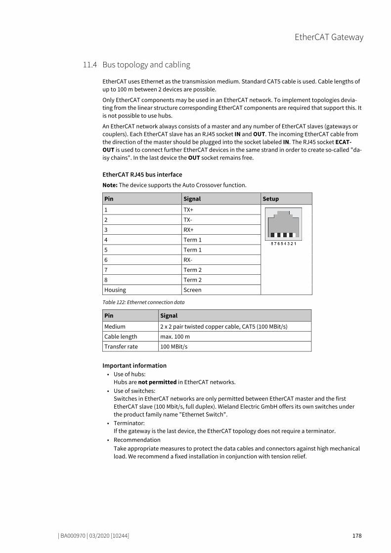
EtherCAT Gateway
| BA000970 | 03/2020 [10244] 178
Bus topology and cabling 79479947
EtherCAT uses Ethernet as the transmission medium. Standard CAT5 cable is used. Cable lengths of up to 100 m between 2 devices are possible.
Only EtherCAT components may be used in an EtherCAT network. To implement topologies devia-ting from the linear structure corresponding EtherCAT components are required that support this. It is not possible to use hubs.
An EtherCAT network always consists of a master and any number of EtherCAT slaves (gateways or couplers). Each EtherCAT slave has an RJ45 socket IN and OUT. The incoming EtherCAT cable from the direction of the master should be plugged into the socket labeled IN. The RJ45 socket ECAT-OUT is used to connect further EtherCAT devices in the same strand in order to create so-called "da-isy chains". In the last device the OUT socket remains free.
EtherCAT RJ45 bus interface Note: The device supports the Auto Crossover function.
Pin Signal Setup
1 TX+
2 TX-
3 RX+
4 Term 1
5 Term 1
6 RX-
7 Term 2
8 Term 2
Housing Screen
Table 122: Ethernet connection data
Pin Signal
Medium 2 x 2 pair twisted copper cable, CAT5 (100 MBit/s)
Cable length max. 100 m
Transfer rate 100 MBit/s
Important information • Use of hubs:
Hubs are not permitted in EtherCAT networks. • Use of switches:
Switches in EtherCAT networks are only permitted between EtherCAT master and the first EtherCAT slave (100 Mbit/s, full duplex). Wieland Electric GmbH offers its own switches under the product family name "Ethernet Switch".
• Terminator: If the gateway is the last device, the EtherCAT topology does not require a terminator.
• Recommendation Take appropriate measures to protect the data cables and connectors against high mechanical load. We recommend a fixed installation in conjunction with tension relief.
11.4
EtherCAT Gateway
| BA000970 | 03/2020 [10244] 179
Data transferred into the network 79543435
Available data The samosPRO EtherCAT gateway can provide the following data: • Process data
– Logic results from the samosPRO (see Routing Table [ch. 5.1.3, p. 44]) – Input values (HIGH/LOW) for all samosPRO input expansion modules in the system – Output values (HIGH/LOW) for all samosPRO input/output expansion modules (see Module
state / input and output values [ch. 3.3.1, p. 25]) – Output data from another network, i.e. data received from a second gateway in the sa-
mosPRO system (see Transmission of data from a second network [ch. 3.3.3, p. 26]) • Diagnostics
– Test values (CRCs) (see Configuration test values (CRCs) [ch. 3.3.4, p. 26]) – Error and state information for all modules (see Error and state information for modules
[ch. 3.3.5, p. 27])
Data sets The physical samosPRO modules are not presented as typical hardware modules in the network. Instead, the data provided by the samosPRO system have been arranged in three input data sets.
11.5

EtherCAT Gateway
| BA000970 | 03/2020 [10244] 180
Data set 1 79559435
Data set 1 (50 bytes) contains the process data. It can be compiled with the aid of samosPLAN 6. In the form in which it is delivered, the content of data set 1 is preconfigured; it can be freely modified.
Note: Not allocated means that the byte value is equal to 0x00. However, the user can freely assign these bytes.
Table 123: Data set: Output data set 1 samosPRO COMPACT to --> SP-EN-ETC
Output data block 1 Output data block 2
Byte 0 Input values for Module 0 (I1..I8) Byte 10 Not allocated
Byte 1 Input values for Module 0 (I9..I16) Byte 11 Not allocated
Byte 2 Input values for Module 0 (IQ1..IQ4) Byte 12 Input values for Module 1
Byte 3 Output values for Module 0 (Q1..Q4, IQ1..IQ4)
Byte 13 Input values for Module 2
Byte 4 Not allocated Byte 14 Input values for Module 3
Byte 5 Not allocated Byte 15 Input values for Module 4
Byte 6 Not allocated Byte 16 Input values for Module 5
Byte 7 Not allocated Byte 17 Input values for Module 6
Byte 8 Not allocated Byte 18 Input values for Module 7
Byte 9 Not allocated Byte 19 Input values for Module 8
Output data block 3 Output data block 4
Byte 20 Input values for Module 9 Byte 30 Output values for Module 7
Byte 21 Input values for Module 10 Byte 31 Output values for Module 8
Byte 22 Input values for Module 11 Byte 32 Output values for Module 9
Byte 23 Input values for Module 12 Byte 33 Output values for Module 10
Byte 24 Output values for Module 1 Byte 34 Output values for Module 11
Byte 25 Output values for Module 2 Byte 35 Output values for Module 12
Byte 26 Output values for Module 3 Byte 36 Not allocated
Byte 27 Output values for Module 4 Byte 37 Not allocated
Byte 28 Output values for Module 5 Byte 38 Not allocated
Byte 29 Output values for Module 6 Byte 39 Not allocated
Output data block 5
Byte 40 Not allocated
Byte 41 Not allocated
Byte 42 Not allocated
Byte 43 Not allocated
Byte 44 Not allocated
Byte 45 Not allocated
Byte 46 Not allocated
Byte 47 Not allocated
Byte 48 Not allocated
Byte 49 Not allocated
Total length
50 bytes
11.5.1

EtherCAT Gateway
| BA000970 | 03/2020 [10244] 181
Tag names pre-assigned in samosPLAN 6 for the EtherCAT gateway The data set 1 is divided into five input data blocks for clarity, whereby data blocks 1 to 5 each con-tain 10 bytes.
It is possible to write values directly from the logic editor to the gateway. These valuesare freely programmable and are transferred to the EtherCAT network in the Transmit PDO. Four bytes have been reserved for this purpose in the basic settings for data set 1; however, up to the total number of 50 bytes of data set 1 may be configured as direct gateway output values. You can obtain additio-nal information at: Direct gateway output values [ch. 3.3.1, p. 25]
The samosPRO gateway can transmit the input and output states of all samosPRO modules connec-ted to the samosPRO system to the network. Data set 3 contains a non-modifiable configuration. Moreover, data set 1 can be adapted to contain up to 4 bytes of collective state information. Only the input and output values for data set 1 have been predefined and these can be freely adapted. You will find more detailed information in the section on the relevant gateway, as well as in the following section: Configuration of gateways with samosPLAN 6 [ch. 5, p. 40]
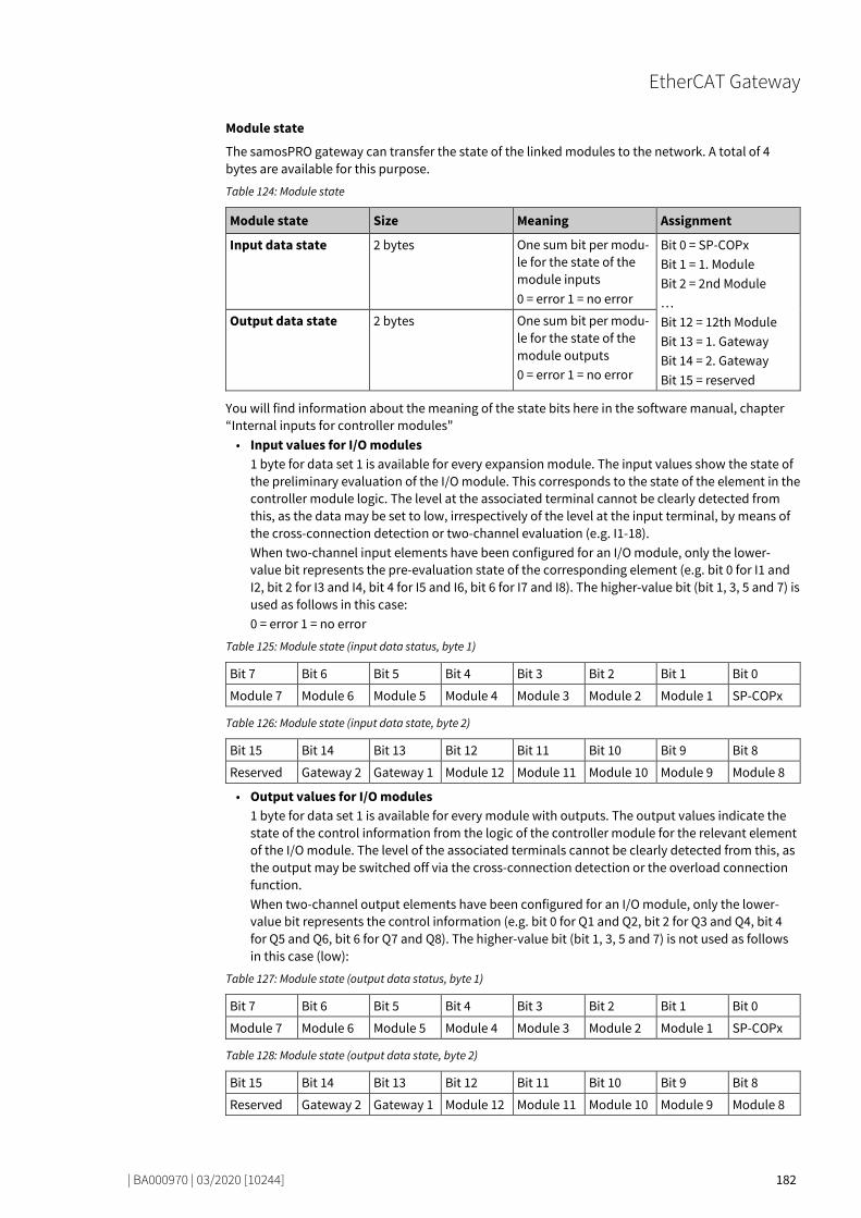
EtherCAT Gateway
| BA000970 | 03/2020 [10244] 182
Module state
The samosPRO gateway can transfer the state of the linked modules to the network. A total of 4 bytes are available for this purpose.
Table 124: Module state
Module state Size Meaning Assignment
Input data state 2 bytes One sum bit per modu-le for the state of the module inputs 0 = error 1 = no error
Bit 0 = SP-COPx Bit 1 = 1. Module Bit 2 = 2nd Module … Bit 12 = 12th Module Bit 13 = 1. Gateway Bit 14 = 2. Gateway Bit 15 = reserved
Output data state 2 bytes One sum bit per modu-le for the state of the module outputs 0 = error 1 = no error
You will find information about the meaning of the state bits here in the software manual, chapter “Internal inputs for controller modules" • Input values for I/O modules
1 byte for data set 1 is available for every expansion module. The input values show the state of the preliminary evaluation of the I/O module. This corresponds to the state of the element in the controller module logic. The level at the associated terminal cannot be clearly detected from this, as the data may be set to low, irrespectively of the level at the input terminal, by means of the cross-connection detection or two-channel evaluation (e.g. I1-18). When two-channel input elements have been configured for an I/O module, only the lower-value bit represents the pre-evaluation state of the corresponding element (e.g. bit 0 for I1 and I2, bit 2 for I3 and I4, bit 4 for I5 and I6, bit 6 for I7 and I8). The higher-value bit (bit 1, 3, 5 and 7) is used as follows in this case: 0 = error 1 = no error
Table 125: Module state (input data status, byte 1)
Bit 7 Bit 6 Bit 5 Bit 4 Bit 3 Bit 2 Bit 1 Bit 0
Module 7 Module 6 Module 5 Module 4 Module 3 Module 2 Module 1 SP-COPx
Table 126: Module state (input data state, byte 2)
Bit 15 Bit 14 Bit 13 Bit 12 Bit 11 Bit 10 Bit 9 Bit 8
Reserved Gateway 2 Gateway 1 Module 12 Module 11 Module 10 Module 9 Module 8
• Output values for I/O modules 1 byte for data set 1 is available for every module with outputs. The output values indicate the state of the control information from the logic of the controller module for the relevant element of the I/O module. The level of the associated terminals cannot be clearly detected from this, as the output may be switched off via the cross-connection detection or the overload connection function. When two-channel output elements have been configured for an I/O module, only the lower-value bit represents the control information (e.g. bit 0 for Q1 and Q2, bit 2 for Q3 and Q4, bit 4 for Q5 and Q6, bit 6 for Q7 and Q8). The higher-value bit (bit 1, 3, 5 and 7) is not used as follows in this case (low):
Table 127: Module state (output data status, byte 1)
Bit 7 Bit 6 Bit 5 Bit 4 Bit 3 Bit 2 Bit 1 Bit 0
Module 7 Module 6 Module 5 Module 4 Module 3 Module 2 Module 1 SP-COPx
Table 128: Module state (output data state, byte 2)
Bit 15 Bit 14 Bit 13 Bit 12 Bit 11 Bit 10 Bit 9 Bit 8
Reserved Gateway 2 Gateway 1 Module 12 Module 11 Module 10 Module 9 Module 8

EtherCAT Gateway
| BA000970 | 03/2020 [10244] 183
Transmission of data from a second network If your samosPRO system contains two gateways, it is possible to forward information which the first gateway receives from a network (e.g. from an EhterCAT PLC) via the second gateway to a second network (e.g. to a PROFIBUS master) and vice versa.
Expert setting: Allocating bytes to other addresses samosPLAN 6 has pre-assigned the addresses according to a default. You can manually change this address allocation by moving any number of bytes.
In our example, we have shifted byte 1 to byte 23 in output data block 0.
Step 1: Check target address Ensure that the desired address (byte 23 in our example) has not been allocated.
When the target address is assigned here, delete the bytes placed there.
To do this, click on the byte in the work area and click on the Delete symbol in the command bar.
Step 2: Delete byte from original address Delete the byte you wish to reallocated (byte 0 in our example).
To do this, click on the byte in the work area and click on the Delete symbol in the command bar.

EtherCAT Gateway
| BA000970 | 03/2020 [10244] 184
Step 3: Place byte on new target address Open the Gateway docking window and select the desired bytes under the associated module.
Use the mouse button to drag the Byte into the work area on byte 23.

EtherCAT Gateway
| BA000970 | 03/2020 [10244] 185
Data set 2 79597835
Data set 2 (32 bytes) contains the check values (CRCs) for the system configuration.
Configuration check values (CRCs) Data set 2 contains the following configuration check values of the samosPRO system: • Project CRC of the project file created with samosPLAN 6. • System CRC, uniquely assigned to a module version, consisting of internal software and hard-
ware version.
The CRCs are each 4 Bytes in length. Data set 2 can be read only.
The project CRC is transmitted in Big Endian format.
Table 129: Output data set 2 samosPRO COMPACT to --> SP-EN-ETC
Byte assignment
Byte 0 Project CRC Value is on the first page in the project report from samosPLAN 6. Example: CRC Station 1: 0x2ac78506
Byte 1
Byte 2
Byte 3
Byte 4 System CRC Caution: Review of this system CRC requires a custom material number and thus a special agreement with Wieland Electric.
Byte 5
Byte 6
Byte 7
Byte 8 to byte 31 Reserved for as yet unknown applications
Length 32 bytes
11.5.2

EtherCAT Gateway
| BA000970 | 03/2020 [10244] 186
Data set 3 79617803
Data set 3 (60 bytes) contains the state and diagnostic data for the various modules, with four (4) bytes per module, with the controller module comprising 3 x 4 bytes. Details: see table "Meaning of module state bits for secure I/O modules" [ch. 3.3.5, p. 28].
Error and state information for the modules Data set 3 contains the state information for the modules that will be transferred to the network.
Ten bytes are transmitted for each controller module. For each SP-SDI or SP-SDIO I/O module, four bytes are transmitted in the little endian format, e.g. as a 32-bit word, with the first byte being placed into the least significant byte of the whole number (extreme left) and the fourth byte into the most significant byte of the whole number (extreme right).
Data set 3 cannot be changed.
NOTICE • Reserved (for future use) = static 1 (no state change) • Not used (can be 0 or 1 ), both values occur. • If there is no module, all values - including the reserved values - are set to logical 1.
Table 130: Output data set 3 samosPRO COMPACT on --> SP-EN-ETC
Byte assignment
Byte 0 Module state SP-COPx
Byte 1 Module state SP-COPx
Byte 2 Test impulse SP-COP inputs
Byte 3 Test impulse SP-COP inputs
Byte 4 Test impulse SP-COP inputs
Byte 5 State of two-channel SP-COP inputs
Byte 6 State of two-channel SP-COP inputs
Byte 7 Reserved
Byte 8 Stuck-at error at SP-COP outputs
Byte 9 Stuck-at error at SP-COP outputs
Byte 10 Reserved
Byte 11 Reserved
Byte 12 Status of Module 1
Byte 13 Status of Module 1
Byte 14 Status of Module 1
Byte 15 Status of Module 1
Byte 16 Status of Module 2
Byte 17 Status of Module 2
Byte 18 Status of Module 2
Byte 19 Status of Module 2
Byte 20 Status of Module 3
Byte 21 Status of Module 3
Byte 22 Status of Module 3
Byte 23 Status of Module 3
Byte 24 Status of Module 4
Byte 25 Status of Module 4
Byte 26 Status of Module 4
11.5.3

EtherCAT Gateway
| BA000970 | 03/2020 [10244] 187
Byte assignment
Byte 27 Status of Module 4
Byte 28 Status of Module 5
Byte 29 Status of Module 5
Byte 30 Status of Module 5
Byte 31 Status of Module 5
Byte 32 Status of Module 6
Byte 33 Status of Module 6
Byte 34 Status of Module 6
Byte 35 Status of Module 6
Byte 36 Status of Module 7
Byte 37 Status of Module 7
Byte 38 Status of Module 7
Byte 39 Status of Module 7
Byte 40 Status of Module 8
Byte 41 Status of Module 8
Byte 42 Status of Module 8
Byte 43 Status of Module 8
Byte 44 Status of Module 9
Byte 45 Status of Module 9
Byte 46 Status of Module 9
Byte 47 Status of Module 9
Byte 48 Status of Module 10
Byte 49 Status of Module 10
Byte 50 Status of Module 10
Byte 51 Status of Module 10
Byte 52 Status of Module 11
Byte 53 Status of Module 11
Byte 54 Status of Module 11
Byte 55 Status of Module 11
Byte 56 Status of Module 12
Byte 57 Status of Module 12
Byte 58 Status of Module 12
Byte 59 Status of Module 12
Length 60 bytes
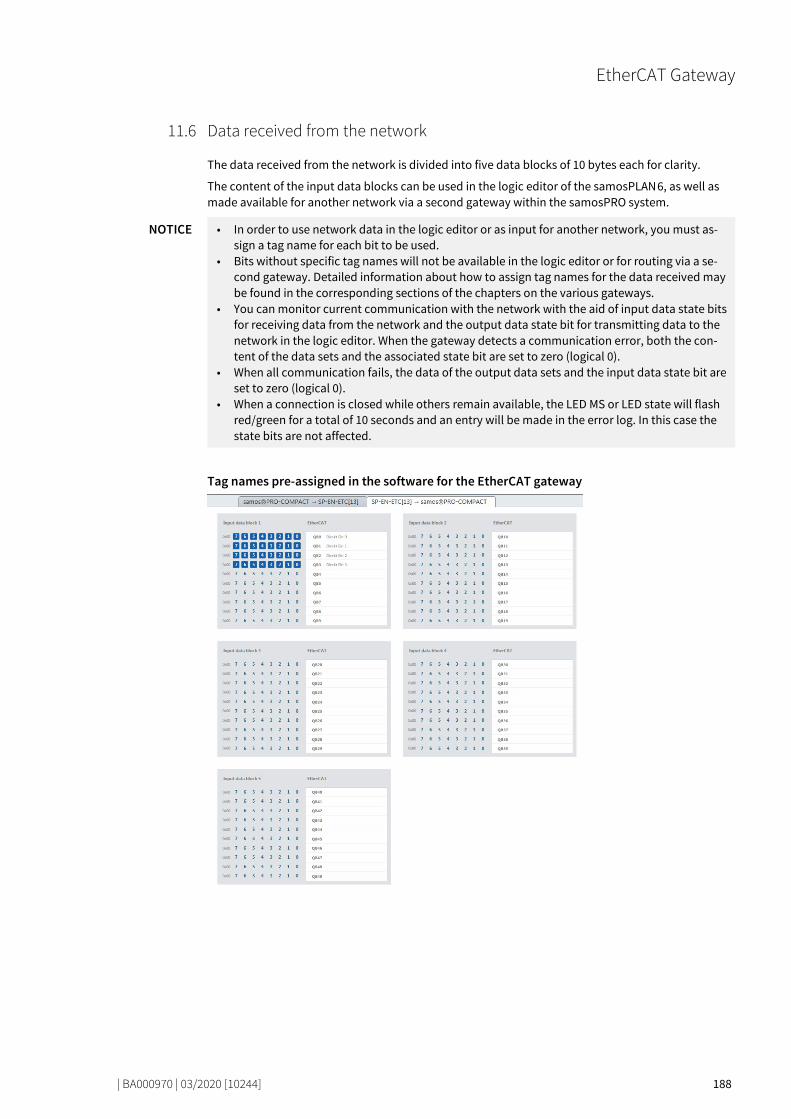
EtherCAT Gateway
| BA000970 | 03/2020 [10244] 188
Data received from the network 79687947
The data received from the network is divided into five data blocks of 10 bytes each for clarity.
The content of the input data blocks can be used in the logic editor of the samosPLAN 6, as well as made available for another network via a second gateway within the samosPRO system.
NOTICE • In order to use network data in the logic editor or as input for another network, you must as-sign a tag name for each bit to be used.
• Bits without specific tag names will not be available in the logic editor or for routing via a se-cond gateway. Detailed information about how to assign tag names for the data received may be found in the corresponding sections of the chapters on the various gateways.
• You can monitor current communication with the network with the aid of input data state bits for receiving data from the network and the output data state bit for transmitting data to the network in the logic editor. When the gateway detects a communication error, both the con-tent of the data sets and the associated state bit are set to zero (logical 0).
• When all communication fails, the data of the output data sets and the input data state bit are set to zero (logical 0).
• When a connection is closed while others remain available, the LED MS or LED state will flash red/green for a total of 10 seconds and an entry will be made in the error log. In this case the state bits are not affected.
Tag names pre-assigned in the software for the EtherCAT gateway
11.6
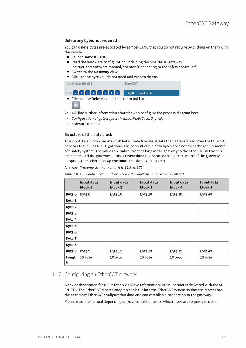
EtherCAT Gateway
| BA000970 | 03/2020 [10244] 189
Delete any bytes not required You can delete bytes pre-allocated by samosPLAN 6 that you do not require by clicking on them with the mouse. Launch samosPLAN 6. Read the hardware configuration, including the SP-EN-ETC gateway.
Instructions: Software manual, chapter "Connecting to the safety controller" Switch to the Gateway view. Click on the byte you do not need and wish to delete.
Click on the Delete icon in the command bar.
You will find further information about how to configure the process diagram here: • Configuration of gateways with samosPLAN 6 [ch. 5, p. 40] • Software manual
Structure of the data block The input data block consists of 50 bytes (byte 0 to 49) of data that is transferred from the EtherCAT network to the SP-EN-ETC gateway. The content of the data bytes does not meet the requirements of a safety system. The values are only current as long as the gateway to the EtherCAT network is connected and the gateway status is Operational. As soon as the state machine of the gateway adopts a state other than Operational, this data is set to zero.
Also see: Gateway state machine [ch. 11.3, p. 177]
Table 131: Input data block 1–5 of the SP-EN-ETC module to --> samosPRO COMPACT
Input data block 1
Input data block 2
Input data block 3
Input data block 4
Input data block 5
Byte 0 Byte 0 Byte 10 Byte 20 Byte 30 Byte 40
Byte 1
Byte 2
Byte 3
Byte 4
Byte 5
Byte 6
Byte 7
Byte 8
Byte 9 Byte 9 Byte 19 Byte 29 Byte 39 Byte 49
Length
10 byte 10 byte 10 byte 10 byte 10 byte
Configuring an EtherCAT network 79720715
A device description file (ESI = EtherCAT Slave Information) in XML format is delivered with the SP-EN-ETC. The EtherCAT master integrates this file into the EtherCAT system so that the master has the necessary EtherCAT configuration data and can establish a connection to the gateway.
Please read the manual depending on your controller to see which steps are required in detail.
11.7

EtherCAT Gateway
| BA000970 | 03/2020 [10244] 190
EtherCAT configuration of the gateway - how the data are transferred 79409803
The following steps are required to configure the communication between the PLC programming system and the gateway. Configuration in the programming system is done by integrating a stan-dardized ESI description file.
NOTICE This documentation does not address the installation of the EtherCAT network or the other com-ponents of the automation system project in the network configuration tool. It is assumed that the EtherCAT project in the configuration program (e.g. Beckhoff TwinCAT) has already been set up. The examples presented are based on configurations created with the help of Beckhoff TwinCAT.
Step 1: Install the EtherCAT slave description file Before the SP-EN-ETC module can be used for the first time as part of the network configuration tool (e.g. Beckhoff TwinCAT), the gateway description file must first be installed in the hardware catalog of the tool. Download the GSD file and the equipment symbol from the product site of the SP-EN-ETC mo-
dule (https://eshop.wieland-electric.com/). Follow the instructions to install XML in the online help or user manual of the EtherCAT network
configuration tool for the master or for the EtherCAT control system.
Step 2: Add the gateway to a PLC project To make the system of the samosPRO system available in the process diagram of the PLC, the gate-way must first be added to the hardware configuration. The procedure to be used depends on the hardware configuration software of the PLC used. Please also read the documentation for the cor-responding software in this regard.
The example below shows how the gateway is added to a control project in Beckhoff TwinCAT. Copy the description file Wieland SP EN ETC V1.1.xml to the TwinCAT folder. An example of a ty-
pical installation can be seen below:
If a path is to be specified in the ESI file in which, for example, the description file for the expan-
sion modules is locates, create this path in the directory exactly as described in the file. Re-start TwinCAT.
Note: The folder with the current description files is only read when the program is restarted.
11.8

EtherCAT Gateway
| BA000970 | 03/2020 [10244] 191
Example: This is not true for the gateway, but is important for other slaves.
Step 3: Create a new project
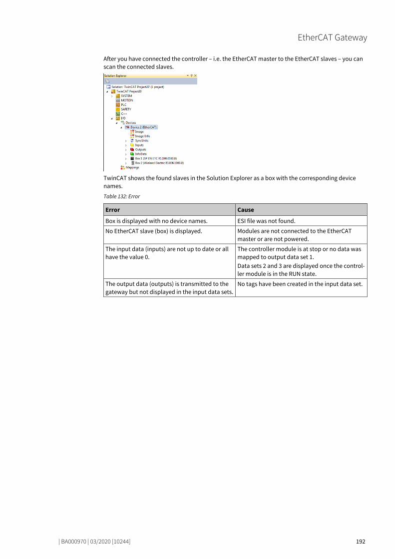
EtherCAT Gateway
| BA000970 | 03/2020 [10244] 192
After you have connected the controller – i.e. the EtherCAT master to the EtherCAT slaves – you can scan the connected slaves.
TwinCAT shows the found slaves in the Solution Explorer as a box with the corresponding device names.
Table 132: Error
Error Cause
Box is displayed with no device names. ESI file was not found.
No EtherCAT slave (box) is displayed. Modules are not connected to the EtherCAT master or are not powered.
The input data (inputs) are not up to date or all have the value 0.
The controller module is at stop or no data was mapped to output data set 1. Data sets 2 and 3 are displayed once the control-ler module is in the RUN state.
The output data (outputs) is transmitted to the gateway but not displayed in the input data sets.
No tags have been created in the input data set.

EtherCAT Gateway
| BA000970 | 03/2020 [10244] 193
Diagnostic LEDs on the gateway and troubleshooting 79444363
You can find information on the diagnosis of the samosPRO system in the software manual.
Table 133: Troubleshooting on the SP-EN-ETC module
Error Possible cause Possible remedy
Key: LED off / LED flashes / LED lights up
samosPLAN 6 cannot set up a connection to the controller module.
• Switch on the power supply. • Check the communication
settings in samosPLAN 6.
The SP-EN-ETC does not pro-vide any input data.
After switch-on: • EtherCAT not connected.
• Connect RJ45 cable to ECAT-IN.
MS LED /
Red / green
The SP-EN-ETC does not pro-vide any input data.
After switch-on: • RJ45 is connected to the
port, no data on the EtherCAT Net.
• Activate EtherCAT.
MS LED /
Red / green
LINK (ETHERCAT-IN)
Green
The SP-EN-ETC does not pro-vide any input data.
After switch-on: • RJ45 is connected to the
port, EtherCAT not acti-ve.
• Activate EtherCAT and initialize Gateway. Init state MS LED
/ Red / green
LINK (ETHERCAT-IN)
Green
Controller errors • Incorrect EtherCAT con-figuration, gateway is addressed with incorrect data.
• Gateway is in Pre-Op state.
• Check network and device configuration.
• Switch power off and back on. MS LED
Red
RUN
Green / flashing
ERR
Red / flashing
LINK Green
The SP-EN-ETC does not pro-vide any input data.
After switch-on: • Gateway state is Init.
• Switch EtherCAT to Op state.
MS LED /
Red / green
LINK Green
LINK Green
11.9
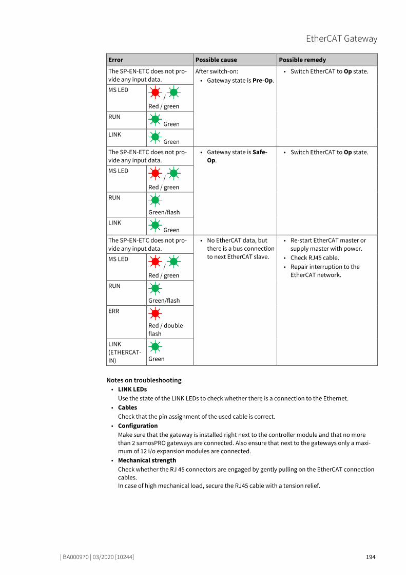
EtherCAT Gateway
| BA000970 | 03/2020 [10244] 194
Error Possible cause Possible remedy
The SP-EN-ETC does not pro-vide any input data.
After switch-on: • Gateway state is Pre-Op.
• Switch EtherCAT to Op state.
MS LED /
Red / green
RUN Green
LINK Green
The SP-EN-ETC does not pro-vide any input data.
• Gateway state is Safe-Op.
• Switch EtherCAT to Op state.
MS LED /
Red / green
RUN
Green/flash
LINK Green
The SP-EN-ETC does not pro-vide any input data.
• No EtherCAT data, but there is a bus connection to next EtherCAT slave.
• Re-start EtherCAT master or supply master with power.
• Check RJ45 cable. • Repair interruption to the
EtherCAT network.
MS LED /
Red / green
RUN
Green/flash
ERR
Red / double flash
LINK (ETHERCAT-IN)
Green
Notes on troubleshooting • LINK LEDs
Use the state of the LINK LEDs to check whether there is a connection to the Ethernet. • Cables
Check that the pin assignment of the used cable is correct. • Configuration
Make sure that the gateway is installed right next to the controller module and that no more than 2 samosPRO gateways are connected. Also ensure that next to the gateways only a maxi-mum of 12 i/o expansion modules are connected.
• Mechanical strength Check whether the RJ 45 connectors are engaged by gently pulling on the EtherCAT connection cables. In case of high mechanical load, secure the RJ45 cable with a tension relief.
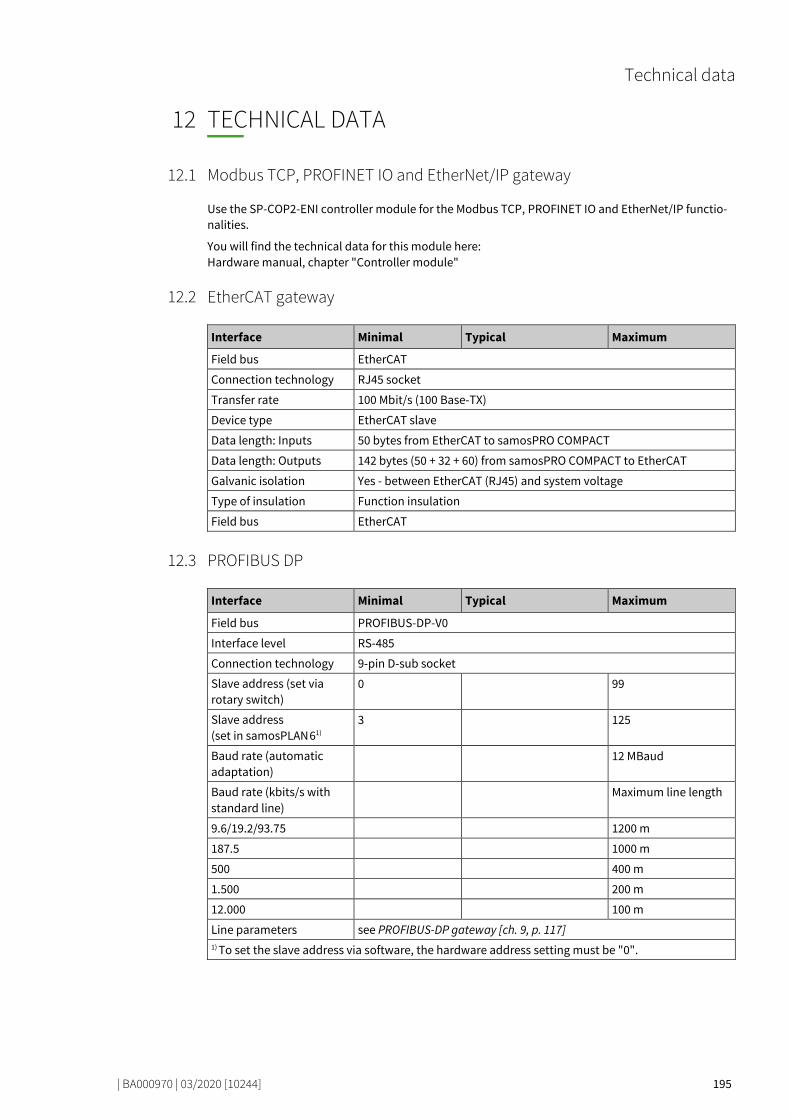
Technical data
| BA000970 | 03/2020 [10244] 195
TECHNICAL DATA
78916107
Modbus TCP, PROFINET IO and EtherNet/IP gateway 79019659
Use the SP-COP2-ENI controller module for the Modbus TCP, PROFINET IO and EtherNet/IP functio-nalities.
You will find the technical data for this module here: Hardware manual, chapter "Controller module"
EtherCAT gateway 79033355
Interface Minimal Typical Maximum
Field bus EtherCAT
Connection technology RJ45 socket
Transfer rate 100 Mbit/s (100 Base-TX)
Device type EtherCAT slave
Data length: Inputs 50 bytes from EtherCAT to samosPRO COMPACT
Data length: Outputs 142 bytes (50 + 32 + 60) from samosPRO COMPACT to EtherCAT
Galvanic isolation Yes - between EtherCAT (RJ45) and system voltage
Type of insulation Function insulation
Field bus EtherCAT
PROFIBUS DP 78925067
Interface Minimal Typical Maximum
Field bus PROFIBUS-DP-V0
Interface level RS-485
Connection technology 9-pin D-sub socket
Slave address (set via rotary switch)
0 99
Slave address (set in samosPLAN 61)
3 125
Baud rate (automatic adaptation)
12 MBaud
Baud rate (kbits/s with standard line)
Maximum line length
9.6/19.2/93.75 1200 m
187.5 1000 m
500 400 m
1.500 200 m
12.000 100 m
Line parameters see PROFIBUS-DP gateway [ch. 9, p. 117] 1) To set the slave address via software, the hardware address setting must be "0".
12
12.1
12.2
12.3
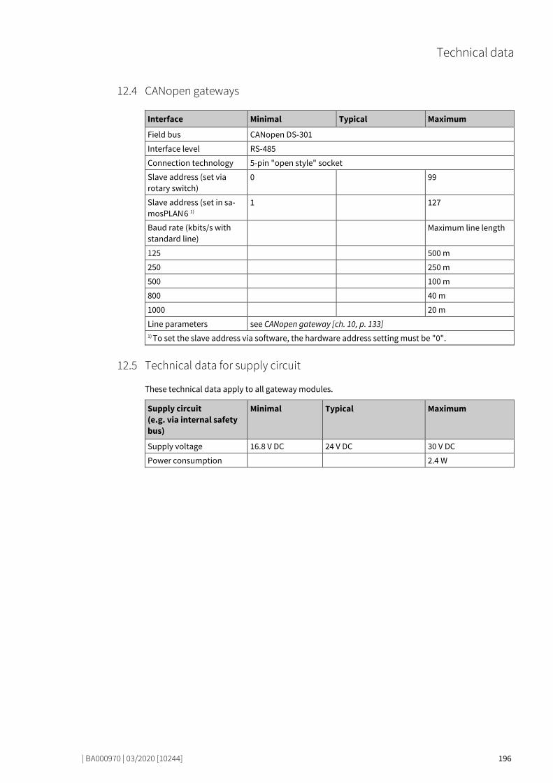
Technical data
| BA000970 | 03/2020 [10244] 196
CANopen gateways 78935307
Interface Minimal Typical Maximum
Field bus CANopen DS-301
Interface level RS-485
Connection technology 5-pin "open style" socket
Slave address (set via rotary switch)
0 99
Slave address (set in sa-mosPLAN 6 1)
1 127
Baud rate (kbits/s with standard line)
Maximum line length
125 500 m
250 250 m
500 100 m
800 40 m
1000 20 m
Line parameters see CANopen gateway [ch. 10, p. 133] 1) To set the slave address via software, the hardware address setting must be "0".
Technical data for supply circuit 78947851
These technical data apply to all gateway modules.
Supply circuit (e.g. via internal safety bus)
Minimal Typical Maximum
Supply voltage 16.8 V DC 24 V DC 30 V DC
Power consumption 2.4 W
12.4
12.5
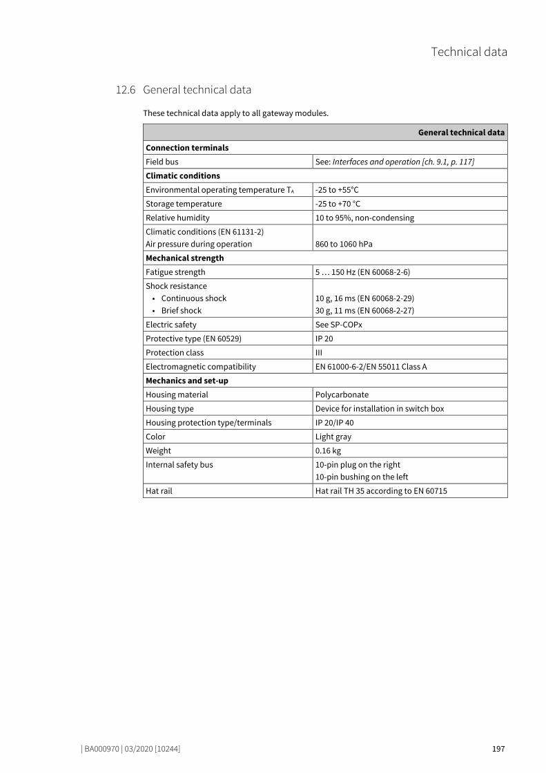
Technical data
| BA000970 | 03/2020 [10244] 197
General technical data 78965643
These technical data apply to all gateway modules.
General technical data
Connection terminals
Field bus See: Interfaces and operation [ch. 9.1, p. 117]
Climatic conditions
Environmental operating temperature TA -25 to +55°C
Storage temperature -25 to +70 °C
Relative humidity 10 to 95%, non-condensing
Climatic conditions (EN 61131-2) Air pressure during operation
860 to 1060 hPa
Mechanical strength
Fatigue strength 5 … 150 Hz (EN 60068-2-6)
Shock resistance • Continuous shock • Brief shock
10 g, 16 ms (EN 60068-2-29) 30 g, 11 ms (EN 60068-2-27)
Electric safety See SP-COPx
Protective type (EN 60529) IP 20
Protection class III
Electromagnetic compatibility EN 61000-6-2/EN 55011 Class A
Mechanics and set-up
Housing material Polycarbonate
Housing type Device for installation in switch box
Housing protection type/terminals IP 20/IP 40
Color Light gray
Weight 0.16 kg
Internal safety bus 10-pin plug on the right 10-pin bushing on the left
Hat rail Hat rail TH 35 according to EN 60715
12.6
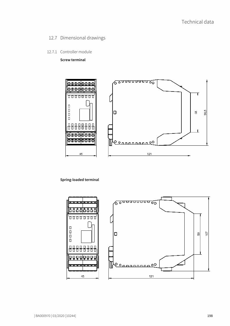
Technical data
| BA000970 | 03/2020 [10244] 198
Dimensional drawings 78985867
Controller module 75815307
Screw terminal
Spring-loaded terminal
12.7
12.7.1

Technical data
| BA000970 | 03/2020 [10244] 199
CANopen and PROFIBUS gateways (old housing) 78994571
Illustration 46: Dimensional drawing CANopen and PROFIBUS gateways (mm)
12.7.2
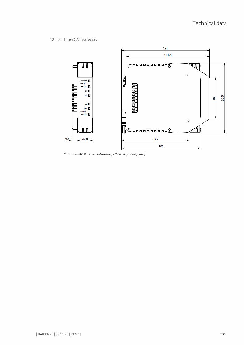
Technical data
| BA000970 | 03/2020 [10244] 200
EtherCAT gateway 79007499
Illustration 47: Dimensional drawing EtherCAT gateway (mm)
12.7.3
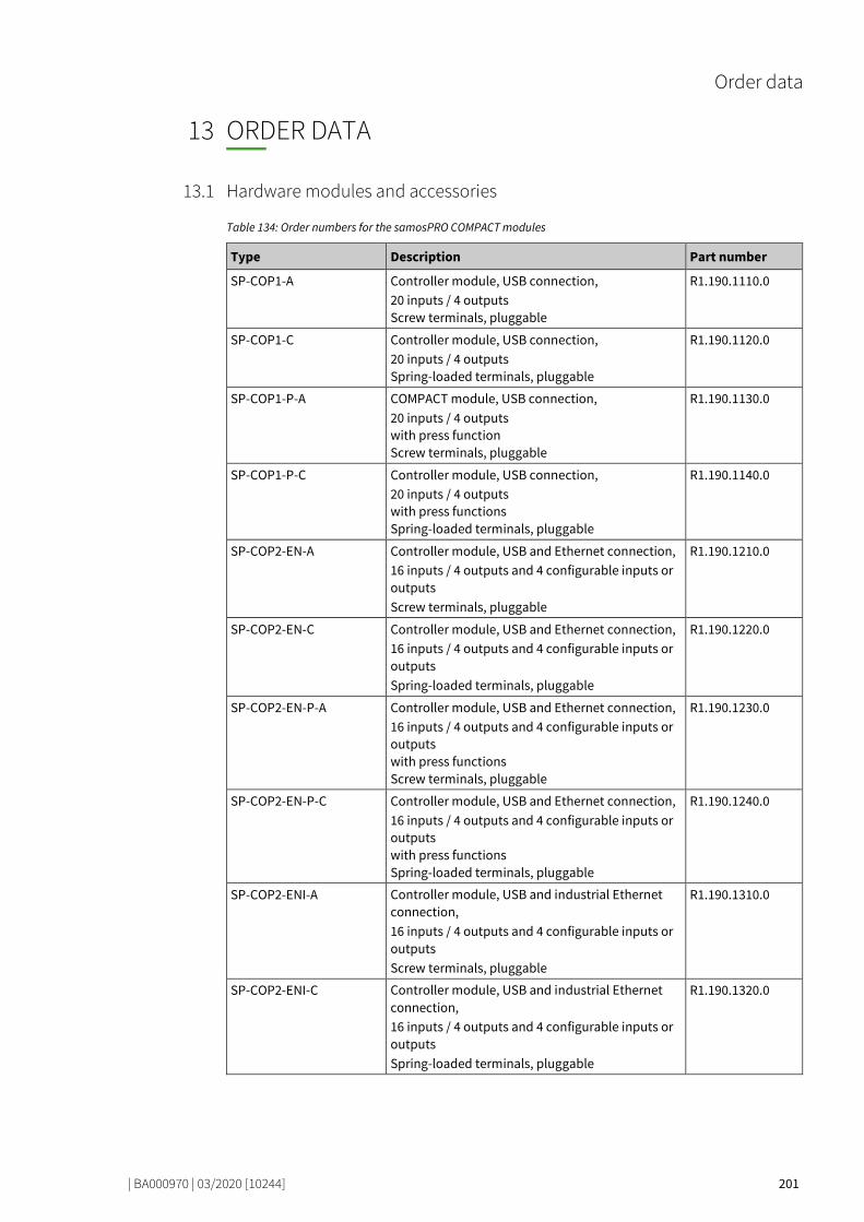
Order data
| BA000970 | 03/2020 [10244] 201
ORDER DATA
75963787
Hardware modules and accessories 75971595
Table 134: Order numbers for the samosPRO COMPACT modules
Type Description Part number
SP-COP1-A Controller module, USB connection, 20 inputs / 4 outputs Screw terminals, pluggable
R1.190.1110.0
SP-COP1-C Controller module, USB connection, 20 inputs / 4 outputs Spring-loaded terminals, pluggable
R1.190.1120.0
SP-COP1-P-A COMPACT module, USB connection, 20 inputs / 4 outputs with press function Screw terminals, pluggable
R1.190.1130.0
SP-COP1-P-C Controller module, USB connection, 20 inputs / 4 outputs with press functions Spring-loaded terminals, pluggable
R1.190.1140.0
SP-COP2-EN-A Controller module, USB and Ethernet connection, 16 inputs / 4 outputs and 4 configurable inputs or outputs Screw terminals, pluggable
R1.190.1210.0
SP-COP2-EN-C Controller module, USB and Ethernet connection, 16 inputs / 4 outputs and 4 configurable inputs or outputs Spring-loaded terminals, pluggable
R1.190.1220.0
SP-COP2-EN-P-A Controller module, USB and Ethernet connection, 16 inputs / 4 outputs and 4 configurable inputs or outputs with press functions Screw terminals, pluggable
R1.190.1230.0
SP-COP2-EN-P-C Controller module, USB and Ethernet connection, 16 inputs / 4 outputs and 4 configurable inputs or outputs with press functions Spring-loaded terminals, pluggable
R1.190.1240.0
SP-COP2-ENI-A Controller module, USB and industrial Ethernet connection, 16 inputs / 4 outputs and 4 configurable inputs or outputs Screw terminals, pluggable
R1.190.1310.0
SP-COP2-ENI-C Controller module, USB and industrial Ethernet connection, 16 inputs / 4 outputs and 4 configurable inputs or outputs Spring-loaded terminals, pluggable
R1.190.1320.0
13
13.1

Order data
| BA000970 | 03/2020 [10244] 202
Type Description Part number
SP-COP2-ENI-P-A Controller module, USB and industrial Ethernet connection, 16 inputs / 4 outputs and 4 configurable inputs or outputs with press functions Screw terminals, pluggable
R1.190.1330.0
SP-COP2-ENI-P-C Controller module, USB and industrial Ethernet connection, 16 inputs / 4 outputs and 4 configurable inputs or outputs with press functions Spring-loaded terminals, pluggable
R1.190.1340.0
SP-COP-CARD1 Program removable storage R1.190.1000.0
SP-CABLE-USB1 1.8 m USB configuration capable R1.190.1010.0
SP-CABLE-ETH1 2 m Ethernet configuration capable R1.190.1020.0
SP-PLAN6 CD with samosPLAN 6 programming software and manuals
R1.190.1030.0
SP-COP-STARTER-SET Kit consisting of one each of SP-COP2-EN-A, SP-SDIO, SP-COP-CARD1, SP-PLAN6, SP-CABLE-USB1
R1.190.1100.0
SP-CANopen CANopen gateway R1.190.0210.1
SP-PROFIBUS-DP PROFIBUS-DP gateway R1.190.0190.1
SP-SDIO84-P1-K-A Safe input/output expansion with output test pulses 8 inputs/4 outputs Screw terminals, pluggable
R1.190.0030.0
SP-SDIO84-P1-K-C Safe input/output expansion with output test pulses 8 inputs/4 outputs Spring-loaded terminals, pluggable
R1.190.0040.0
SP-SDI8-P1-K-A Safe input expansion 8 inputs Screw terminals, pluggable
R1.190.0050.0
SP-SDI8-P1-K-C Safe input expansion 8 inputs Spring-loaded terminals, pluggable
R1.190.0060.0
SP-DIO84-P1-K-A Standard input/output expansion 4 inputs / 4 outputs and 4 configurable inputs or outputs Screw terminals, pluggable
R1.190.1050.0
SP-DIO84-P1-K-C Standard input/output expansion 4 inputs / 4 outputs and 4 configurable inputs or outputs Screw-loaded terminals, pluggable
R1.190.1060.0
SP-SAR4-A Analog module, 4 safe RTD inputs, screw termi-nals, pluggable
R1.190.1610.0
SP-SAR4-C Analog module, 4 safe RTD inputs, spring-loaded terminals, pluggable
R1.190.1620.0
SP-SAC4-A Analog module, 4 safe 0-20mA inputs, screw ter-minals, pluggable
R1.190.1630.0
SP-SAC4-C Analog module, 4 safe 0-20mA inputs, spring-loaded terminals, pluggable
R1.190.1640.0
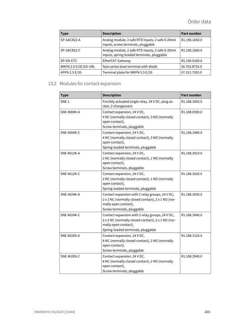
Order data
| BA000970 | 03/2020 [10244] 203
Type Description Part number
SP-SACR22-A Analog module, 2 safe RTD inputs, 2 safe 0-20mA inputs, screw terminals, pluggable
R1.190.1650.0
SP-SACR22-C Analog module, 2 safe RTD inputs, 2 safe 0-20mA inputs, spring-loaded terminals, pluggable
R1.190.1660.0
SP-EN-ETC EtherCAT Gateway R1.190.0160.0
WKFN 2.5 E/35 GO-URL fasis series level terminal with diode 56.703.8755.9
APFN 2.5 E/35 Terminal plate for WKFN 2.5 E/35 07.312.7355.0
Modules for contact expansion 76021131
Type Description Part number
SNE 1 Forcibly actuated single relay, 24 V DC, plug so-cket, 2 changeovers
R1.188.3950.0
SNE 4004K-A Contact expansion, 24 V DC, 4 NC (normally closed contact), 3 NO (normally open contact), Screw terminals, pluggable
R1.188.0590.0
SNE 4004K-C Contact expansion, 24 V DC, 4 NC (normally closed contact), 3 NO (normally open contact), Spring-loaded terminals, pluggable
R1.188.1980.0
SNE 4012K-A Contact expansion, 24 V DC, 2 NC (normally closed contact), 1 NO (normally open contact), Screw terminals, pluggable
R1.188.3910.0
SNE 4012K-C Contact expansion, 24 V DC, 2 NC (normally closed contact), 1 NO (normally open contact), Spring-loaded terminals, pluggable
R1.188.3920.0
SNE 4024K-A Contact expansion with 2 relay groups, 24 V DC, 2 x 2 NC (normally closed contact), 2 x 1 NO (nor-mally open contact), Screw terminals, pluggable
R1.188.3930.0
SNE 4024K-C Contact expansion with 2 relay groups, 24 V DC, 2 x 2 NC (normally closed contact), 2 x 1 NO (nor-mally open contact), Spring-loaded terminals, pluggable
R1.188.3940.0
SNE 4028S-A Contact expansion, 24 V DC, 8 NC (normally closed contact), 2 NO (normally open contact), Screw terminals, pluggable
R1.188.3120.0
SNE 4028S-C Contact expansion, 24 V DC, 8 NC (normally closed contact), 2 NO (normally open contact), Screw terminals, pluggable
R1.188.3540.0
13.2

77123979
Wieland Electric GmbH Brennerstraße 10 – 14 96052 Bamberg · Germany
Phone +49 951 9324-0 Fax +49 951 9324-198 [email protected] www.wieland-electric.com