Embed Size (px)
Citation preview

FISHERIES DEVELOPMENT SECTION REPORT
OF
SEA AND FISHING TRIALS ON BOARD THE SAMOAN
FISHERIES DIVISION’S NEW 12.2 M SUPER ALIA
26 April – 4 September 2000
by
William SokimiFisheries Development Officer
and
Lindsay ChapmanFisheries Development Adviser
© Copyright Secretariat of the Pacific Community 2000
All rights for commercial / for profit reproduction or translation, in any form, reserved. The SPC autho-rises the partial reproduction or translation of this material for scientific, educational or research pur-poses, provided the SPC and the source document are properly acknowledged. Permission to reproducethe document and/or translate in whole, in any form, whether for commercial / for profit or non-profitpurposes, must be requested in writing. Original SPC artwork may not be altered or separately pub-lished without permission.
Original text: English
Secretariat of the Pacific Community cataloguing-in-publication data
Sokimi, William
Sea and fishing trials on board the Samoan Fisheries Division’s new 12.2 m super alia, 26 April – 4September 2000 / by William Sokimi and Lindsay Chapman
(Report / Fisheries Development Section)
1. Fisheries – Samoa. 2. Fishing – Samoa – Equipment and supplies. 3. Fishing boats.
1. Title 2. Secretariat of the Pacific Community 3. Series 4. Chapman, Lindsay
639.22 AACR2
ISSN 1605–446
ISBN 982–203–757–0
Secretariat of the Pacific CommunityBP D598848 Noumea CedexNew CaledoniaTelephone: + 687 26 20 00Facsimile: + 687 26 38 18E-mail: [email protected]://www.spc.int/coastfish
Prepared for publication atSecretariat of the Pacific Community headquarters
Noumea, New Caledonia, 2000
Printed by Graphoprint, Noumea, New Caledonia
ii
ACKNOWLEDGEMENTS
The Secretariat of the Pacific Community (SPC) acknowledges with gratitude the co-operation pro-vided by the administration and staff of the Samoa Fisheries Division and the tremendous support andassistance they have given the Fisheries Development Officers during the course of this project. Specialappreciation and thanks are directed to Mr Ueta Fa'asili, Assistant Director (Fisheries); Mr Peter Watt,AusAID Commercial Fisheries Extension Advisor (during Stage II); Mr Savali Time, Senior FisheriesOfficer (Development); Mr Toni Mulipola, Principal Fisheries Officer (Resource Assessment); MrKelvin Passfield, AusAID Fisheries Adviser; Mr Roy Peters, Boatbuilder; the crew of F/V Ulimasao,Mr Pesaleli Toatu (Skipper), Mr Fou Fuli, Mr Livi Faleau, Mr Michael Forsythe, and Mr Ielu Faleau;and fishing vessel operators, Mr Kim Levi, Mr Raymond Slate, Mr Peter Rasch and Mr Leau ChuShing.
The authors are also grateful to those involved in the production of this report, in particular, Ms Marie-Ange Roberts for the format and layout as well as drawing many of the diagrams, Ms Sarah Langi forediting, and Ms Patricia Martin for the design of the cover. The authors also thank the SPC’s transla-tion staff for translating the summary.
The Fisheries Development Section gratefully acknowledges the financial support of AusAID, whofully funded the project and the production of this report.
iii

SUMMARY
The Samoan tuna longline fishery has developed rapidly over the last five years, with the main vesselused being the alia catamaran. These vessels target albacore tuna, which is landed locally, frozen, andexported to the two canneries in neighbouring American Samoa. An increasing component of the catchfrom the Samoan longline fishery is the catch of higher-value species, such as larger yellowfin and big-eye tunas. These fish are landed to processors, who export them fresh to overseas markets.
In 1999, the SPC provided technical assistance to the Samoan Fisheries Division designed to increasethe catch of higher-value tuna species for the fresh export market, and to provide training in severalareas. The catch rates recorded for the higher-valued species were consistent with the catches obtainedby local fishermen. The training component of the project was very successful, especially in the areaof on-board fish handling, processing and preservation. The current report draws on the results andbackground information of the 1999 project (Sokimi et al., 2000).
The alia catamaran is limited with regard to the weight it can carry; the capacity of insulated areas tochill and store the catch; stability; size; navigation equipment; and crew comfort. To overcome theselimitations, the Fisheries Division had a new super alia designed and constructed, and requested tech-nical assistance from SPC’s Fisheries Development Section to supervise the sea and fishing trials onthis new vessel. The main objectives of the project were to assess the effectiveness of the new vesselas a suitable tuna longliner under Samoan conditions; make recommendations on any changes thatcould improve the fishing operation and vessel layout; and train the skipper and crew to operate thenew vessel.
The results of the longline fishing and sea trials on board the new 12.2 m super alia, F/V Ulimasao,were very encouraging. The vessel is feasible for the fishing operations in Samoa and has proven itselfover the eleven trips that were conducted. The present design is adequate to conduct full-scale longlinefishing operations and is much better than that of the smaller alias in the fishery. The increased sizeand stability of the vessel, the insulated fish holds below deck, the added safety and efficiency of thetwin diesel engines, and the cabin for accommodation and the latest navigational equipment, all makethis a good small-scale tuna longliner that appears to work well under Samoan fishing conditions.
The twin Yanmar engines performed admirably and demonstrated that the horsepower produced byboth engines was more than sufficient to power a boat of this size and take the load of the hydraulicfishing gear. Fuel consumption by these engines showed that the vessel could be run economically.While the original plans for the vessel indicate that it can carry up to four tonnes of ice, the trialsshowed that for practical purposes, 1.8 t is more realistic and comfortable to work with. This however,limits the amount of fish that can be correctly iced.
The trials on F/V Ulimasao were conducted under semi-commercial circumstances. However, despitethis limitation, the economics of the operation based on the achieved saleable catch were profitable andencouraging. The overall catch of saleable fish at 16,838 kg with a wholesale value of WST 81,957 wasgood for the vessel under trial fishing conditions. If this vessel was fished commercially, it is project-ed that 40 to 60 trips could be undertaken per year, depending on fishing strategy, with three sets pertrip. The anticipated catch would range from 80 to 121 t with an estimated wholesale value rangingfrom WST 392,717 to WST 589,075. After all fixed and variable costs (including wages for the skip-per and crew) are taken into consideration, the anticipated profit would range from WST 77,474 toWST 184,560.
Several improvements can be made to the vessel, the fishing operation, and the ongoing maintenanceof the vessel. These are detailed in this report.
v

RÉSUMÉ
La flottille de bateaux de pêche thonière à la palangre, composée essentiellement de catamarans Alia,s'est rapidement développée au cours de ces cinq dernières années. Ces unités ciblent le germon qui estdébarqué localement, congelé et exporté vers deux conserveries des Samoa américaines voisines. Lesespèces à valeur commerciale plus élevée, telles que les thons jaunes et les thons obèses de grandetaille, deviennent une partie croissante des prises réalisées par la flottille de palangriers du Samoa. Cespoissons sont débarqués et pris en charge par des spécialistes de la transformation qui les exportent àl'état frais vers des marchés étrangers.
En 1999, la CPS a fourni une aide technique au Service des pêches du Samoa afin de lui permettre d'aug-menter ses prises d'espèces de thonidés à plus forte valeur commerciale, destinées à l'exportation de pro-duits frais, et elle a assuré une formation dans plusieurs domaines. Les taux de prise enregistrés pour cetype d'espèces ont correspondu à ceux réalisés par les pêcheurs locaux. Par contre, l'action de formations'est soldée par un franc succès, en particulier pour ce qui est de la manipulation, de la transformation etde la conservation à bord du poisson. Le présent rapport a été établi d'après les résultats du projet mis enœuvre en 1999 et les informations générales fournies à cette occasion (Sokimi et al., 2000).
Le catamaran Alia a certains points faibles sous les aspects suivants : sa charge utile, la capacité descoffres isothermes où les prises sont réfrigérées et stockées, sa stabilité, sa taille, le matériel de navi-gation et le confort de l'équipage. Pour y remédier, le Service des pêches a commandé un super Alia deconception et de fabrication nouvelles et il a demandé à la section Développement de la pêche de laCPS de bien vouloir superviser, dans le cadre d'une mission d'assistance technique, des essais en meret des essais de pêche de cette nouvelle unité. Les principaux objectifs de ce projet étaient d'évaluer sice navire serait un bon bateau de pêche thonière à la palangre dans les conditions de navigation et depêche dans les eaux du Samoa, de recommander éventuellement des changements de nature à amélior-er la configuration du navire et ses performances dans le cadre d'opérations de pêche, et de former lepatron de pêche et les membres d'équipage à l'exploitation de cette nouvelle unité.
Les résultats des essais de pêche à la palangre et des essais en mer réalisés à bord du nouveau superAlia de 12,20 mètres, l'Ulimasao, ont été très encourageants. Le bateau est bien adapté aux opérationsde pêche au Samoa et il a fait la preuve de ses qualités au cours des onze sorties qui ont été réalisées.Le modèle actuel est adapté à des opérations de pêche à la palangre de grande envergure et il est biensupérieur aux Alias de plus petite taille qui font partie de la flottille. Les plus grandes dimensions et lastabilité accrue du bateau, les coffres à poissons isothermes placés sous le pont, la sécurité et le meilleurrendement des deux moteurs diesel jumelés, ainsi que les aménagements apportés à la cabine et la miseen place des instruments de navigation les plus modernes, tout cela fait du super Alia un bon bateau depêche artisanale du thon à la palangre, qui semble bien répondre aux conditions de pêche du Samoa.
Les deux moteurs Yanmar ont fonctionné admirablement et démontré que la puissance de ces deuxengins couplés était plus que suffisante pour propulser un bateau de cette taille et supporter la charged'un engin de pêche hydraulique. La consommation de carburant a montré que le navire était d'uneexploitation économique. Si, d'après les plans, le navire peut emporter jusqu'à quatre tonnes de glace, lesessais ont démontré qu'à des fins pratiques, il est plus réaliste et plus commode de n'embarquer que 1,8tonne. Néanmoins, cette limitation n'est pas sans incidence sur la quantité de poisson qui peut être cor-rectement mise sous glace.
Les essais réalisés sur l'Ulimasao l'ont été dans des circonstances semi-commerciales. Cependant, malgrécette limitation, au vu des prises de poissons commercialisables, il s'est avéré que l'exploitation du navireétait rentable et prometteuse. Le volume total des prises commercialisables (16 838 kg d'une valeur auprix de gros de 81 957 talas) a été bon, étant donné que le bateau a été utilisé dans des conditions de pêcheexpérimentale. S'il l'était dans une visée commerciale, il pourrait réaliser 40 à 60 sorties par an selon letype de pêche employé, avec trois calées par sortie. Le volume de prises anticipé se situerait entre 80 et121 tonnes, représentant une valeur estimée sur le marché de gros de 392 717 à 589 075 talas. Après avoirtenu compte de tous les coûts fixes et variables (y compris les salaires du patron de pêche et des membresd'équipage), on pourrait escompter des bénéfices de l'ordre de 77 474 à 184 560 talas.
Plusieurs améliorations peuvent être apportées au navire, aux opérations de pêche et à l'entretien per-manent du navire. Elles sont présentées en détail dans ce rapport.
vii

CONTENTS
1. INTRODUCTION AND BACKGROUND 1
1.1 Samoa 1
1.2 Development of the Samoan offshore fishery 2
1.2.1 History of the alia catamaran and the offshore fisheries it has been used in 21.2.2 Limitations and problems encountered with the alia catamaran 41.2.3 Fisheries Division’s efforts to overcome alia limitations 5
1.3 Initiation of the project and its objectives 6
2. PROJECT VESSEL F/V ULIMASAO 6
2.1 Description and layout of F/V Ulimasao 7
2.1.1 Crew accommodation, toilet and galley 82.1.2 Gear storage holds 82.1.3 Fish holds 92.1.4 Main engines and engine rooms 102.1.5 Bilge and fish-hold pumps 102.1.6 Main engine cooling line, toilet flush line and salt water tap line 102.1.7 Fuel and fresh water tanks 102.1.8 Electrical system 112.1.9 Hydraulic system for fishing operation 122.1.10 Steering system 132.1.11 Mainline reel and line shooter 132.1.12 Hauling station 15
2.2 Work completed on the project vessel after launching and modifications during sea trials 15
2.2.1 Work completed before the first fishing trip 152.2.2 Modifications and adjustments made during fishing trials 16
2.3 Temperature/depth recording (TDR) equipment used on the project vessel 19
3. PROJECT ACTIVITIES, ON-BOARD TRAINING AND CATCH RESULTS 19
3.1 Selection of fishing grounds 20
3.2 Fishing gear and method 20
3.2.1 Gear used 203.2.2 Method used 213.2.3 Management of working space 233.2.4 Fish preparation and icing 23
3.3 Training 25
3.4 Results of fishing activities 25
3.5 Comparison of catch rates 26
3.6 Results from the temperature/depth recording (TDR) equipment 27
3.7 Disposal of the catch 28
3.8 Results of sea trials 28
ix
4. ECONOMICS OF THE FISHING OPERATION 29
4.1 Income from fish sales 29
4.2 Costs associated with the vessel and expenditure for the fishing operation 30
4.2.1 Fixed costs 314.2.2 Variable costs 31
4.3 Projection of annual vessel economics and viability 32
5. DISCUSSION AND CONCLUSIONS 32
5.1 Changes and modifications to the vessel 33
5.2 Changes and modifications to the fishing gear and operation 36
5.3 Vessel maintenance 38
6. RECOMMENDATIONS 40
6.1 Changes and modifications to the vessel 40
6.2 Changes and modifications to the fishing gear and operation 41
6.3 Vessel maintenance 42
7. REFERENCES 43
APPENDICES
A Specifications for the 12.2 m super alia, F/V Ulimasao 45
B Main engine starting procedures prior to departure 47
C Procedures to be followed prior to and during line setting and line hauling 49
D Summary of longline catches taken from the super alia F/V Ulimasao 51
E Species composition of the tuna longline catch 55
F Costs associated with the construction and rigging of F/V Ulimasao as 57provided by the Samoan Fisheries Division (some fishing gear costs estimated)
G Summary of vessel operating expenses incurred during the project 59
H Engine running hours and fuel consumption by trip 61
x
1. INTRODUCTION AND BACKGROUND
1.1 Samoa
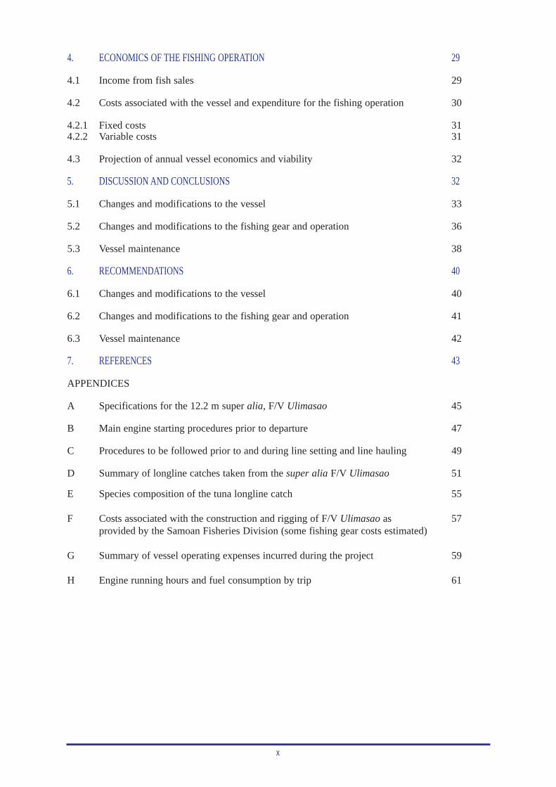
Samoa (Figure 1), formerly Western Samoa, has its land area bounded between latitudes 13° 25' S and14° 05' S, and longitudes 171° 23' W and 172° 48' W. The island group comprises two major islands,Upolu (1108 km2) and Savaii (1695 km2); two smaller inhabited islands, Manono and Apolima; andfour uninhabited islands (Passfield & Mulipola, 1999). Flora and fauna consist of palm trees (mainlycoconut), pandanus, pocket areas of mangroves, and secondary growth woodland along the coastalregion. The rest of the islands are covered in thick tropical vegetation, except on recent lava flows (Wattet al., 1998).
1
Figure 1: The islands of Samoa
The mid-1999 population estimate for Samoa was 169,200 people (SPC, 2000). Roughly the samenumber of Samoans have migrated to other countries, particularly New Zealand (Watt & Moala, 1999).The 1991 Samoan census classifies 89 per cent of the population as Polynesian.
Samoa’s economy depends on several industries common to many Pacific Island countries and territo-ries: fisheries, coconut-based products, agriculture, tourism and remittances from Samoans living over-seas. Of these, fisheries plays a major role in foreign exchange, local business growth, employment anddomestic food supply. The development of commercial offshore fisheries between 1975 and 1980, anda further boost in recent years, has allowed several support businesses to flourish. Subsistence fishingis of equal importance in the development of fisheries.
1.2 Development of the Samoan offshore fishery
Samoa, like most Pacific Island nations, places great importance on fisheries and marine resources.Traditionally, Samoans have depended on the sea to supplement their diet. Even today, subsistence andartisanal fishing activities are still an important part of Samoan society. The current trend towards amore cash-based economy has prompted several enterprising locals to capitalise commercially on off-shore fisheries products, mainly tuna.
There are many technical and social issues associated with industry growth, that the SamoanGovernment has had to consider. These include infrastructure, sustainability of stocks, decisions toexpand or restrain vessel numbers, market competition and marketing in general, viable products, sea-safety issues, training requirements, and social impacts.
Samoa has the smallest Exclusive Economic Zone (EEZ) in the Pacific region, covering only130,000 km2 (Passfield & Mulipola, 1999). However, in recent years, the development of the domestictuna longline fishery has generated catches and export earnings of 2,092 t in 1996 (WST 13.8 million—one WST = USD 0.30 cents) and 4,872 t in 1997 (WST 27.5 million). In 1998, tuna exports came to avalue of approximately WST 29.6 million with an export weight of 5,072 t, making fisheries the cur-rent major export earner in Samoa, (Watt & Moala, 1999).
Because fisheries is the number-one industry in the country, and earns the most foreign exchange, theSamoa Fisheries Division recognises the need to improve the current status of fisheries by carefullymonitoring and controlling activities. To achieve this, the Samoan Government sought assistance fromthe Australian Agency for International Development (AusAID) and established an extension service(Samoa Fisheries Project). The aim was to work with existing government agencies to achieve the goalsand strategies necessary for the future development and sustainability of commercial fisheries. Amongother work, research was carried out by the Commercial Fisheries Extension Advisor to find out whattraining is required for the offshore industry, to estimate how much fish is rejected by the tuna indus-try (from canneries and local processors), and to determine the need for further infrastructure in thedeveloping tuna industry.
Samoans have chosen a catamaran design for their vessels, rather than the more traditional dugoutcanoe with a single or double outrigger for stability, or a conventional monohull design. Their prefer-ence for this design is mainly because it is more comfortable to work on at sea as it is stable, and hasa spacious deck area, when compared to monohulls of the same size. Other advantages of the catama-ran design include a lower fuel consumption and faster travelling speed due to the streamlined hulls.
Overall, tuna longlining has rapidly developed through the efforts of the Samoan Fishing Industry andthe Fisheries Division. The alia catamaran was at the forefront of this development, assisting fisher-men to expand into several fisheries from the 1970s through the 1990s. With this expansion came thecontinued evolution of the alia, which created new issues, such as sea safety and fish quality, to beaddressed by the Fisheries Division and local fishermen.
1.2.1 History of the alia catamaran and the offshore fisheries it has been used in
The offshore fishery in Samoa began when up to 120 plywood catamaran-type alia vessels were builtunder a joint FAO/DANIDA project from 1975 to 1979 (Fa’asili & Time, 1997). These original aliaswere 8.9 m long and 2.72 m wide, powered by a single 25 hp outboard engine, with an 8 hp outboardcarried as a spare for safety.
At the end of the 1970s, the original design was altered, with aluminium replacing plywood for the con-struction of the hulls. They were also lengthened to 9.0 m and the outboard size increased to 40 hp.Over 200 of these alias were constructed, and some were exported to other countries (King & Fa’asili,1997).
2
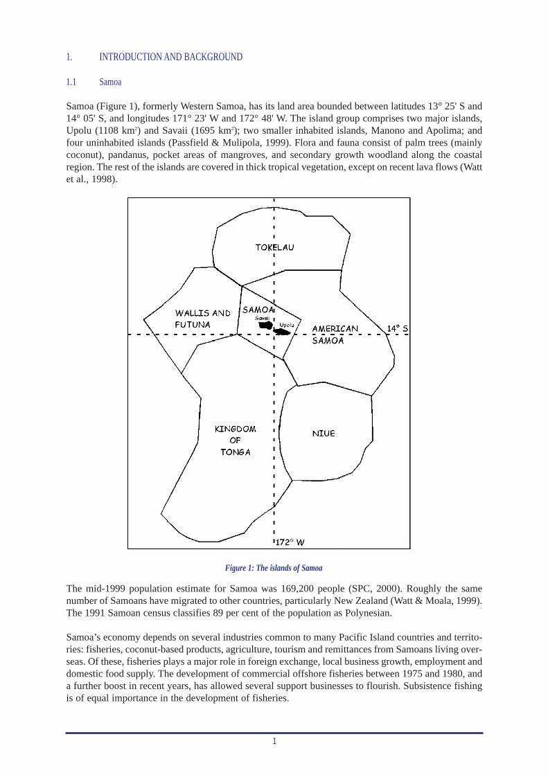
The alias were used offshore, for deep-water bottom fishing in depths to 400 m, and trolling aroundFish Aggregating Devices (FADs). The vessels were fitted with four wooden Samoan handreels andtwo trolling booms (Figure 2) to conduct these fishing activities.
3
Figure 2: The original aluminium alia catamaran rigged with handreels and trolling booms
Catches from deep-bottom fishing were consistent through the late 1970s and early 1980s at around400 t annually. This catch increased to over 500 t in 1984, and peaked in 1986 at around 950 t (Anon.,1998). Trolling catches from around FADs were also consistent over the same period with peak land-ings of over 1,600 t recorded in 1986 and 1988 (Anon., 1998).
Two cyclones in 1990 and 1991 devastated the alia fleet; over half of the vessels were destroyed and manyothers damaged. It was estimated that only 40 useable alias remained after the cyclone in 1991 (Fa’asili,1997). The Government of Samoa used its US Treaty funds, administered by the Forum Fisheries Agency(FFA), to rebuild the fleet. Around 60 alias were back in operation in 1993 (Fa’asili & Time, 1997).
In 1990, the Government of Samoa approached SPC’s Fisheries Programme for technical assistanceto promote offshore fishing. An SPC Fisheries Development Officer was then assigned to Samoa forsix months (September 1990 to March 1991). The aims of the project were to develop and rig the fish-eries research vessel R/V Tautai Matapalapala with tuna fishing gear, and to conduct experimentalvertical and horizontal longlining trials targeting albacore tuna (Thunnus alalunga), yellowfin tuna(T. albacares) and bigeye tuna (T. obesus). Results from the vertical longline trials conducted aroundFADs were successful, with 1,866 kg of fish caught in 13 fishing trips (Watt et al., 1998).
Given the success of the vertical longline trials, SPC technical assistance was extended by four months(March to July 1991). The aim of the extension was to transfer the equipment and technology used onthe research vessel to the alia catamaran, which was the style of vessel used by local fishermen. Thesetrials were also successful, not only in terms of catch (2,819 kg of fish taken in 20 fishing trips), butthe numbers of local fishermen that geared up and fished (Watt et al., 1998).
The horizontal tuna longline trials conducted during the initial SPC visit were considered inconclusive.This was attributed to the limited number of trips, the short mainline (only 4.5 km), and an inappro-priate hydraulic reel being used (Watt et al., 1998).
A combination of the SPC trials and the loss of FADs through natural disasters and other elements ledlocal fishermen to try offshore horizontal longline fishing. In addition, soon after the SPC trials,impressive catches achieved by a 15 m tuna longliner (F/V Marengo Bay), successfully demonstratedthe effectiveness of horizontal longline fishing in Samoan waters (Passfield & Mulipola, 1999).
4
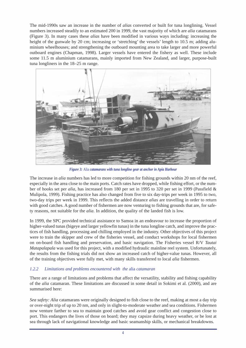
The mid-1990s saw an increase in the number of alias converted or built for tuna longlining. Vesselnumbers increased steadily to an estimated 200 in 1999, the vast majority of which are alia catamarans(Figure 3). In many cases these alias have been modified in various ways including: increasing theheight of the gunwale by 20 cm; increasing or ‘stretching’ the vessels’ length to 10.5 m; adding alu-minium wheelhouses; and strengthening the outboard mounting area to take larger and more powerfuloutboard engines (Chapman, 1998). Larger vessels have entered the fishery as well. These includesome 11.5 m aluminium catamarans, mainly imported from New Zealand, and larger, purpose-builttuna longliners in the 18–25 m range.
Figure 3: Alia catamarans with tuna longline gear at anchor in Apia Harbour
The increase in alia numbers has led to more competition for fishing grounds within 20 nm of the reef,especially in the area close to the main ports. Catch rates have dropped, while fishing effort, or the num-ber of hooks set per alia, has increased from 180 per set in 1995 to 320 per set in 1999 (Passfield &Mulipola, 1999). Fishing practice has also changed from five to six day-trips per week in 1995 to two,two-day trips per week in 1999. This reflects the added distance alias are travelling in order to returnwith good catches. A good number of fishermen are now venturing to fishing grounds that are, for safe-ty reasons, not suitable for the alia. In addition, the quality of the landed fish is low.
In 1999, the SPC provided technical assistance to Samoa in an endeavour to increase the proportion ofhigher-valued tunas (bigeye and larger yellowfin tunas) in the tuna longline catch, and improve the prac-tices of fish handling, processing and chilling employed in the industry. Other objectives of this projectwere to train the skipper and crew of the fisheries vessel, and conduct workshops for local fishermenon on-board fish handling and preservation, and basic navigation. The Fisheries vessel R/V TautaiMatapalapala was used for this project, with a modified hydraulic mainline reel system. Unfortunately,the results from the fishing trials did not show an increased catch of higher-value tunas. However, allof the training objectives were fully met, with many skills transferred to local alia fishermen.
1.2.2 Limitations and problems encountered with the alia catamaran
There are a range of limitations and problems that affect the versatility, stability and fishing capabilityof the alia catamaran. These limitations are discussed in some detail in Sokimi et al. (2000), and aresummarised here:
Sea safety: Alia catamarans were originally designed to fish close to the reef, making at most a day tripor over-night trip of up to 20 nm, and only in slight-to-moderate weather and sea conditions. Fishermennow venture farther to sea to maintain good catches and avoid gear conflict and congestion close toport. This endangers the lives of those on board; they may capsize during heavy weather, or be lost atsea through lack of navigational knowledge and basic seamanship skills, or mechanical breakdowns.
5
Vessel construction: During the mid-1990s, modifications were made to the alia, stretching the length,increasing the freeboard, and adding more powerful outboards. However, the hulls were still made fromthe same thickness of aluminium (2.5 mm). It is also reported that the changes to the design were donewithout the input of a naval architect.
Loss of life: Over a 15-month period between 1997 and 1998, 25 lives were lost at sea in 14 major acci-dents (Watt & Moala, 1999). These accidents were attributed to changes in vessel design, the greaterfishing distances travelled, and in some cases the adverse weather conditions encountered.
Fish quality: Samoa has a high rate of tuna rejected from local processors and the two canneries inAmerican Samoa, where the majority of albacore tuna catches are sold. Fish are rejected as a result ofpoor on-board handling and chilling practices, extended fishing trips with limited or no ice used to chillthe catch, and in some cases, poor onshore freezing practices. Watt and Moala (1999) reported rejec-tion rates of 2.8 per cent in 1996 and 4.2 per cent in 1998 from the two tuna canneries in AmericanSamoa. Local exporters estimated their rejection rate at 5.0 per cent in 1996, 4.4 per cent in 1997, and6.0 per cent in 1998.
Vessel design: The 9 m alias were originally designed for inshore and offshore bottom fishing, trollingand vertical longline fishing, and not for horizontal longline fishing. In addition, no provision was madefor proper insulated ice holds to be constructed within the hulls of the alia catamaran. Portable icebox-es (Eski coolers or fish bags) or cast-off domestic refrigerators are used. This restricts the amount offish that can be properly chilled, resulting in poor-quality fish.
Working area and crew comfort: Nearly all alias carry only three crew members. Three are notenough to perform the setting and hauling duties, and at the same time attend to fish preparation andpreservation during the hauling operation. In addition, the cabin on the alias is small, has limitedcooking facilities (a charcoal stove made from cement poured into a biscuit tin), and no bunks forthe crew to sleep in on longer fishing trips.
Qualifications and training: Very few skippers or crew of the alias have any formal training in nav-igation, seamanship skills, boat safety, and fish handling. Neither do they hold formal qualificationsas skippers or engineers. This is believed to be a contributing factor to the loss of some vessels, asskippers and crew operate from a limited knowledge base, and may not be able to get out of difficultsituations.
1.2.3 Fisheries Division’s efforts to overcome alia limitations
The Samoan Fisheries Division is aware of the limitations and problems associated with the alia catamarans,and has implemented a range of measures to address them. The following is a summary of the measuresimplemented by the Fisheries Division from Sokimi et al. (2000).
Sea safety: A continuous radio watch is maintained by the Fisheries Division, which provides regularweather news and warnings to fishermen at sea. Each licensed vessel is required to carry a VHF radioand report in on departure and arrival. All offshore fishing-vessel owners are encouraged to registertheir vessels or face penalties. There have also been several public displays to demonstrate the varioussafety equipment available to fishermen.
Fish quality: Local fishermen are being encouraged by the Fisheries Division and local processors tocarry ice when going to sea to chill their catch and improve fish quality. Fish processors are making theice available at an affordable price.
Training in fish quality and basic navigation skills: The Fisheries Division AusAID Extension Serviceand SPC have jointly run several workshops focused on on-board fish handling and preservation, andbasic navigation and the use of GPS (global positioning system) (Sokimi et al., 2000). These haveproved to be very successful.
6
Vessel construction and design: The Fisheries Division has identified the need to introduce an advanceddesign for a small-scale fishing vessel that will be able to fish within all areas of Samoa’s EEZ. In late1999, construction commenced on a prototype super alia (12.2 m catamaran with twin diesel inboardengines) that would contain the latest amenities for tuna longline fishing and advanced navigation. Thissingle initiative could have the greatest impact on reducing most of the problems currently occurringin the domestic tuna longline fishery in Samoa.
1.3 Initiation of the project and its objectives
During the final stages of the Fisheries Development Section’s technical assistance to Samoa in late1999, SPC’s Fisheries Development Officer involved in the project was asked to provide input to thelayout of the new super alia under construction in Samoa at the time. This input was provided in a briefreport (Sokimi et al., 2000), and outlined some changes to the deck layout that would assist the fishingoperation of the vessel.
The Fisheries Division placed a very high priority on the construction of the super alia, since, ifthe vessel proved successful, it would overcome many of the problems encountered by local aliafishermen. Fisheries were also keen to ensure that the super alia would be put through rigoroussea and fishing trials to prove its effectiveness as a suitable tuna longliner for the Samoan fishery.In support of this, the Fisheries Division officially requested technical assistance from SPC inFebruary 2000 to conduct the initial sea and fishing trials, and modify the fishing arrangement asrequired. A Memorandum of Agreement was signed between the Government of Samoa and SPCin early April 2000, which clearly defined the roles and responsibilities of both parties and theobjectives of the project. The project commenced on 26 April 2000, when Fisheries DevelopmentOfficer, William Sokimi, arrived in Samoa. The objectives of the project were to:
• conduct sea and tuna longlining trials from the newly designed and constructed fisheries super alia,F/V Ulimasao, to assess its effectiveness as a suitable tuna longline vessel fishing under Samoanconditions;
• recommend modifications or improvements to the fishing gear and fishing layout of F/V Ulimasaobased on the sea and fishing trials, and implement these changes wherever possible;
• train the skipper and crew of the fisheries vessel, F/V Ulimasao, and other interested fishermen, in theuse of the monofilament fishing gear, the hydraulic fishing system, and the correct on-board handling,processing and icing practices for tunas and other species, especially export quality fish; and
• write a comprehensive report on the project outlining the seaworthiness of F/V Ulimasao, anyimprovements and modifications made to the vessel, or needed in the future, the catches achievedduring the fishing trials with a costing of all aspects of the fishing operation, and conclusions andrecommendations.
The project was originally scheduled to run for three months. However, the Fisheries Divisionrequested an extension to the project in June 2000, as problems encountered with the mainline reelresulted in some project time being lost. The project was therefore extended by six weeks, to coverlost fishing time and to allow the skipper and crew to be trained in the use of a new hydraulic main-line reel installed on F/V Ulimasao in July 2000.
2. PROJECT VESSEL F/V ULIMASAO
The project vessel, F/V Ulimasao, is a new prototype offshore fishing catamaran (12.2 m super alia)that has the latest amenities for safe navigation, efficient sea survival equipment, modern tuna longlinefishing gear, ample storage space for producing quality fish, stability, proper crew accommodation andtwin diesel engines that are economical to operate. The vessel resulted from a project proposal that was
7
developed by the Samoan Fisheries Division, and approved by Government. The Forum FisheriesAgency (FFA), using the Project Development Fund under the US Treaty, duly granted an initial sumof USD 116,700 to activate the project and commence the building of the vessel (Anon, unpub.).
A consultant naval architect, Mr Arild Overa, was given the task of producing a plan for the constructionof the super alia. Mr Roy Peters and a work crew carried out construction of the vessel at Tony Hill’sBoatyard in Vaitele, Apia under a voluntary work arrangement with the Fisheries Division. This deal wasagreed to between the two parties with the understanding that the boat builder would have free access andcopies of the plans after the vessel had been completed. The initial number of 11 voluntary workersreduced to seven after two weeks, due to work commitments and personal agendas that had to be met bythe departing crew. During the later stages of vessel construction, seven experienced boat builders had tobe hired to continue the construction work.
The construction schedule of the super alia did not correspond with the Fisheries Division’s original plans.The contract for designing the vessel was acknowledged on 1 March 1999, with the delivery date of the plansbeing three months (1 June 1999). Construction was to have started immediately after receiving the plans. Theplans were finally received on 7 September 1999, and a contract for construction of the vessel was set for 40working days, to be completed by 5 November 1999. Further delays occurred that prevented the realisationof the original completion date of the vessel. The initial estimated cost of constructing the vessel had also risen,which prompted the Fisheries Division to approach FFA for two additional amounts of funding (USD 44,468and 9,248).
The vessel was finally launched on 4 April 2000. Instead of the 40 days estimated for constructing thevessel, the actual construction time came to 23 weeks or 160 days (Anon, unpub.). On 6 April 2000,the vessel was officially christened F/V Ulimasao, which means ‘to steer straight’ or ‘to steer safely’.
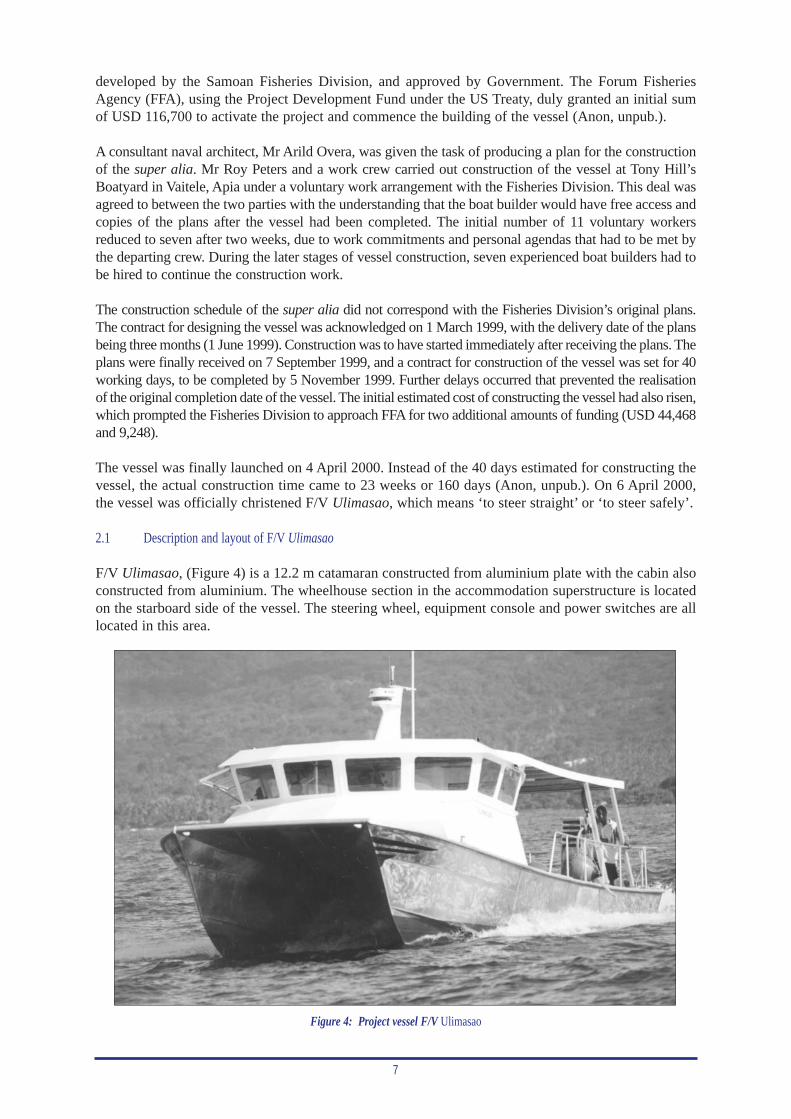
2.1 Description and layout of F/V Ulimasao
F/V Ulimasao, (Figure 4) is a 12.2 m catamaran constructed from aluminium plate with the cabin alsoconstructed from aluminium. The wheelhouse section in the accommodation superstructure is locatedon the starboard side of the vessel. The steering wheel, equipment console and power switches are alllocated in this area.
Figure 4: Project vessel F/V Ulimasao
8
The electronic equipment purchased for navigation and fishing purposes were within a moderate pricerange, sufficient to enable the professional operation of the vessel. These were all centrally located so thatthe vessel’s operator can navigate, steer the vessel, keep a safe lookout and carry out fishing operations.
The vessel is powered by twin 48 hp Yanmar diesel engines with a through-hull drive. The main featuresof the vessel are presented in this section, while Appendix A summarises the main specifications of thevessel.
2.1.1 Crew accommodation, toilet and galley
The wheelhouse, dining table, sleeping quarters and galley are all located under a single superstructure.The vessel is capable of comfortably accommodating six crew. The sleeping arrangement allows forfive crew to be resting at any one time, with the sixth crew member maintaining watch.
There are two main bunks in the accommodation area; one single, and one double. Seats around thedining table also serve as beds for two crew.
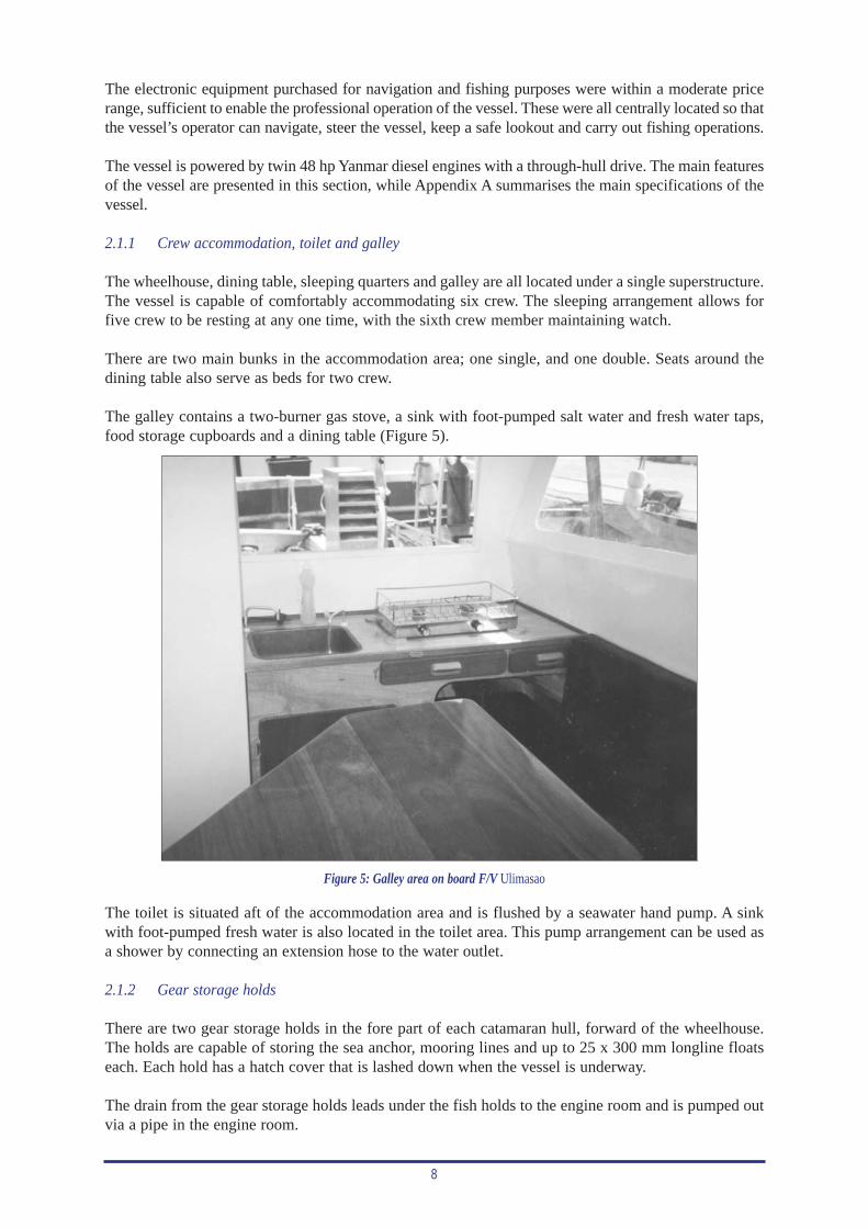
The galley contains a two-burner gas stove, a sink with foot-pumped salt water and fresh water taps,food storage cupboards and a dining table (Figure 5).
Figure 5: Galley area on board F/V Ulimasao
The toilet is situated aft of the accommodation area and is flushed by a seawater hand pump. A sinkwith foot-pumped fresh water is also located in the toilet area. This pump arrangement can be used asa shower by connecting an extension hose to the water outlet.
2.1.2 Gear storage holds
There are two gear storage holds in the fore part of each catamaran hull, forward of the wheelhouse.The holds are capable of storing the sea anchor, mooring lines and up to 25 x 300 mm longline floatseach. Each hold has a hatch cover that is lashed down when the vessel is underway.
The drain from the gear storage holds leads under the fish holds to the engine room and is pumped outvia a pipe in the engine room.
9
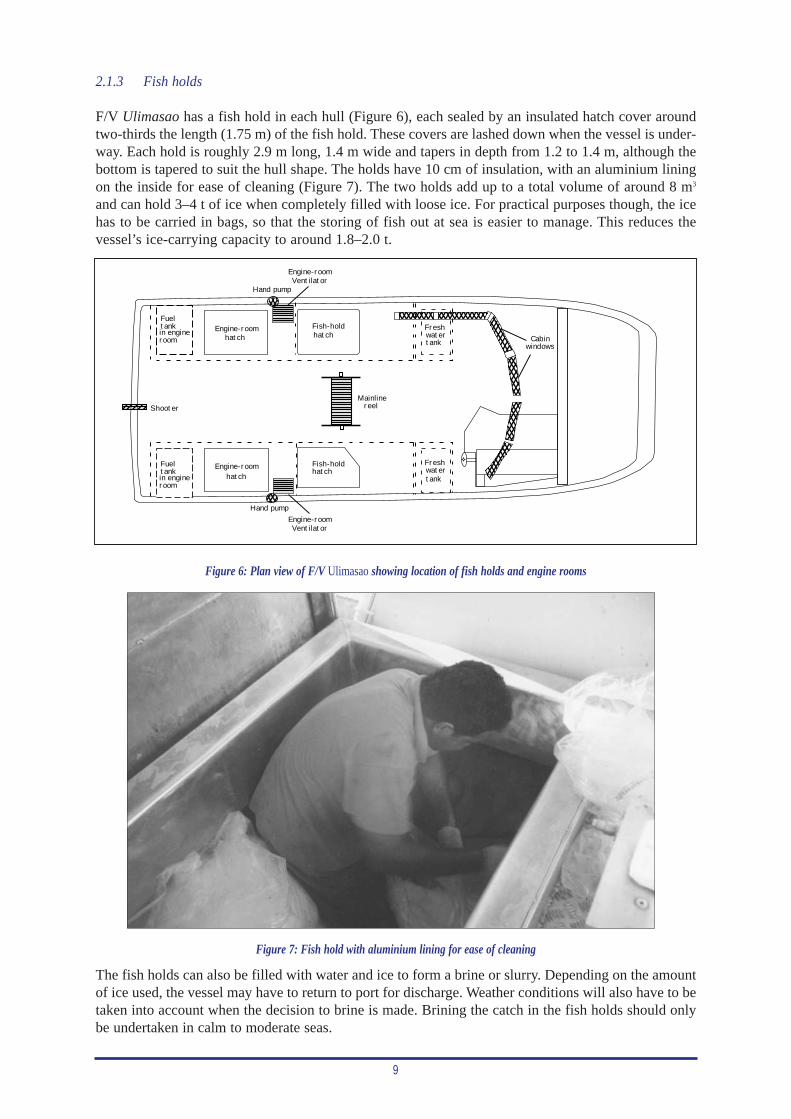
2.1.3 Fish holds
F/V Ulimasao has a fish hold in each hull (Figure 6), each sealed by an insulated hatch cover aroundtwo-thirds the length (1.75 m) of the fish hold. These covers are lashed down when the vessel is under-way. Each hold is roughly 2.9 m long, 1.4 m wide and tapers in depth from 1.2 to 1.4 m, although thebottom is tapered to suit the hull shape. The holds have 10 cm of insulation, with an aluminium liningon the inside for ease of cleaning (Figure 7). The two holds add up to a total volume of around 8 m3
and can hold 3–4 t of ice when completely filled with loose ice. For practical purposes though, the icehas to be carried in bags, so that the storing of fish out at sea is easier to manage. This reduces thevessel’s ice-carrying capacity to around 1.8–2.0 t.
Hand pump
Fish-holdhatch
Fish-holdhatch
Hand pump
VentilatorEngine-room
VentilatorEngine-room
Engine-roomhatch
Engine-roomhatch
Fueltankin engineroom
Fueltankin engineroom
Mainlinereel
Freshwatertank
Freshwatertank
Shooter
Cabinwindows
Figure 6: Plan view of F/V Ulimasao showing location of fish holds and engine rooms
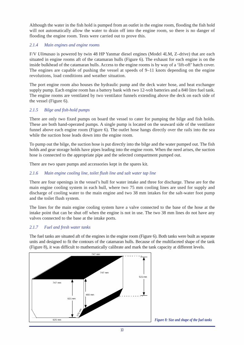
Figure 7: Fish hold with aluminium lining for ease of cleaning
The fish holds can also be filled with water and ice to form a brine or slurry. Depending on the amountof ice used, the vessel may have to return to port for discharge. Weather conditions will also have to betaken into account when the decision to brine is made. Brining the catch in the fish holds should onlybe undertaken in calm to moderate seas.
10
Although the water in the fish hold is pumped from an outlet in the engine room, flooding the fish holdwill not automatically allow the water to drain off into the engine room, so there is no danger offlooding the engine room. Tests were carried out to prove this.
2.1.4 Main engines and engine rooms
F/V Ulimasao is powered by twin 48 HP Yanmar diesel engines (Model 4LM, Z–drive) that are eachsituated in engine rooms aft of the catamaran hulls (Figure 6). The exhaust for each engine is on theinside bulkhead of the catamaran hulls. Access to the engine rooms is by way of a ‘lift-off’ hatch cover.The engines are capable of pushing the vessel at speeds of 9–11 knots depending on the enginerevolutions, load conditions and weather situation.
The port engine room also houses the hydraulic pump and the deck water hose, and heat exchangersupply pump. Each engine room has a battery bank with two 12-volt batteries and a 840 litre fuel tank.The engine rooms are ventilated by two ventilator funnels extending above the deck on each side ofthe vessel (Figure 6).
2.1.5 Bilge and fish-hold pumps
There are only two fixed pumps on board the vessel to cater for pumping the bilge and fish holds.These are both hand-operated pumps. A single pump is located on the seaward side of the ventilatorfunnel above each engine room (Figure 6). The outlet hose hangs directly over the rails into the seawhile the suction hose leads down into the engine room.
To pump out the bilge, the suction hose is put directly into the bilge and the water pumped out. The fishholds and gear storage holds have pipes leading into the engine room. When the need arises, the suctionhose is connected to the appropriate pipe and the selected compartment pumped out.
There are two spare pumps and accessories kept in the spares kit.
2.1.6 Main engine cooling line, toilet flush line and salt water tap line
There are four openings in the vessel’s hull for water intake and three for discharge. These are for themain engine cooling system in each hull, where two 75 mm cooling lines are used for supply anddischarge of cooling water to the main engine and two 38 mm intakes for the salt-water foot pumpand the toilet flush system.
The lines for the main engine cooling system have a valve connected to the base of the hose at theintake point that can be shut off when the engine is not in use. The two 38 mm lines do not have anyvalves connected to the base at the intake ports.
2.1.7 Fuel and fresh water tanks
The fuel tanks are situated aft of the engines in the engine room (Figure 6). Both tanks were built as separateunits and designed to fit the contours of the catamaran hulls. Because of the multifaceted shape of the tank(Figure 8), it was difficult to mathematically calibrate and mark the tank capacity at different levels.
521 mm
747 mm
747 mm
747 mm
621 mm
275
mm
625 mm
460 mm
Figure 8: Size and shape of the fuel tanks
11
To overcome this problem a valve was connected to the bottom of the tank from which a clear hose wasconnected. To check the fuel level the valve is opened to allow the fuel to flow up the clear hose andshow the level at which it settles.
Both tanks now have calibration marks to indicate the amount of fuel remaining at different levels. Thecalibration marks range from zero to 540 l at 40 l intervals, then from 540 to 840 l marked at 100 lintervals. These marks are notched into the side of the tank, directly in line with the hose, so that thelevel in the hose can be compared against them.
To obtain these calibrations, both tanks were emptied then refilled using a 20 litre drum and marked atthe 40, then 100 l intervals. Although the vessel statistics show a maximum capacity of 1,500 l (referAppendix A), each tank can actually hold 840 l, bringing the total capacity to 1,680 l.
Two fresh-water tanks are located under the floor, aft of the bunks in the accommodation area(Figure 6) and have a total capacity of 1,000 l. These tanks are also made to suit the shape of thevessel’s hull.
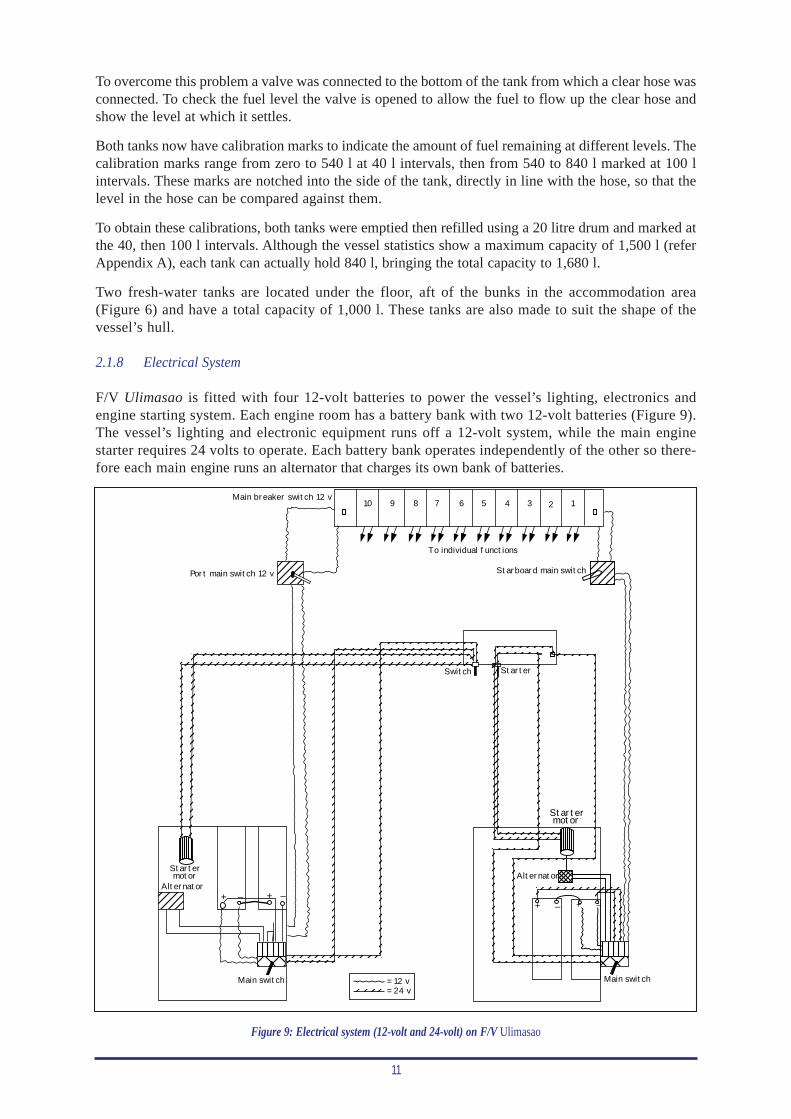
2.1.8 Electrical System
F/V Ulimasao is fitted with four 12-volt batteries to power the vessel’s lighting, electronics andengine starting system. Each engine room has a battery bank with two 12-volt batteries (Figure 9).The vessel’s lighting and electronic equipment runs off a 12-volt system, while the main enginestarter requires 24 volts to operate. Each battery bank operates independently of the other so there-fore each main engine runs an alternator that charges its own bank of batteries.
= 12 v= 24 v
+ – + –+ – + –
Main switch Main switch
Alternator
Startermotor
Port main switch 12 v
Main breaker switch 12 v
To individual functions
Starboard main switch
StarterSwitch
Alternator
Startermotor
12345678910
Figure 9: Electrical system (12-volt and 24-volt) on F/V Ulimasao
12
The power lines for the 12-volt and 24-volt systems both run from the battery terminals to a masterswitch in each engine room. This switch must be kept on at all times while the engine is running. Thisis to enable full function of all the navigation equipment, allows the alternator to keep the batteriescharged, and avoids backload on the alternator.
The lines for the 12-volt system run from the master switch in the engine room to a main switch besidethe switchboard. From the main switch, the line goes to the individual breaker switches for differentfunctions via a main breaker switch on the switchboard. Both the port and starboard systems have theirown main switch and main breaker switch at the switchboard (Figure 9). When the starboard system isused, the port main switch at the switchboard must be shut down; and vice versa, for when the portsystem is used. If both systems are turned on at the same time, 12-volt power will enter the switch-board from both battery banks and will cause an electrical shortage at the switchboard.
The 24-volt system is used only for starting the main engines. The lines for this system run from thebattery bank to the master switch in the engine room then onto the engine starter switches in the wheel-house. From here, the line runs to the starter motor on the main engines.
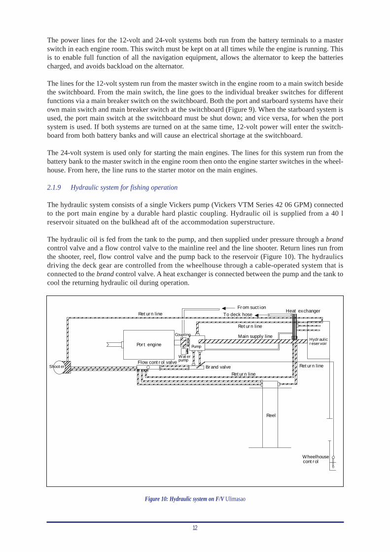
2.1.9 Hydraulic system for fishing operation
The hydraulic system consists of a single Vickers pump (Vickers VTM Series 42 06 GPM) connectedto the port main engine by a durable hard plastic coupling. Hydraulic oil is supplied from a 40 lreservoir situated on the bulkhead aft of the accommodation superstructure.
The hydraulic oil is fed from the tank to the pump, and then supplied under pressure through a brandcontrol valve and a flow control valve to the mainline reel and the line shooter. Return lines run fromthe shooter, reel, flow control valve and the pump back to the reservoir (Figure 10). The hydraulicsdriving the deck gear are controlled from the wheelhouse through a cable-operated system that isconnected to the brand control valve. A heat exchanger is connected between the pump and the tank tocool the returning hydraulic oil during operation.
Port engine
Flow control valveBrand valve
Return line
Reel
Return line
Wheelhousecontrol
Hydraulicreservoir
Main supply line
Return line
Pump
Coupling
Waterpump
Return lineFrom suction
Heat exchangerTo deck hose
Shooter
Figure 10: Hydraulic system on F/V Ulimasao
13
A second, backup hydraulic system was connected to the starboard engine and trialled. The first attemptat hooking up this system resulted in the starboard pump being starved of hydraulic oil. The hydraulicsengineer suggested that a ‘T’ connection in the main oil supply system might have contributed to thisproblem. When one pump is run at a higher speed to the other, it tends to draw all the oil flow towardsit, thus starving the other pump of oil. Therefore the pump on the starboard engine was dismantled andthe hose system sealed until the hydraulics engineer could set up a workable arrangement.
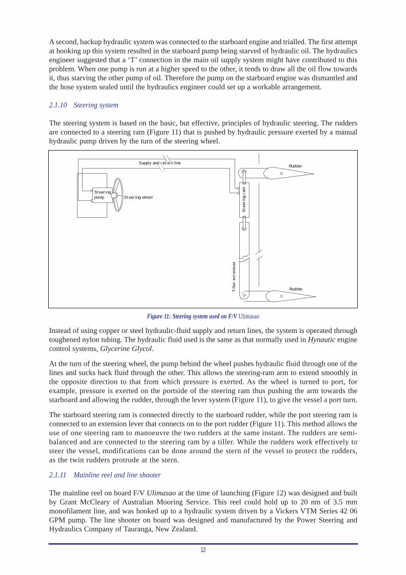
2.1.10 Steering system
The steering system is based on the basic, but effective, principles of hydraulic steering. The ruddersare connected to a steering ram (Figure 11) that is pushed by hydraulic pressure exerted by a manualhydraulic pump driven by the turn of the steering wheel.
Rudder
Rudder
Tille
r ex
tens
ion
Stee
ring
ram
Supply and return line
Steeringpump Steering wheel
Figure 11: Steering system used on F/V Ulimasao
Instead of using copper or steel hydraulic-fluid supply and return lines, the system is operated throughtoughened nylon tubing. The hydraulic fluid used is the same as that normally used in Hynautic enginecontrol systems, Glycerine Glycol.
At the turn of the steering wheel, the pump behind the wheel pushes hydraulic fluid through one of thelines and sucks back fluid through the other. This allows the steering-ram arm to extend smoothly inthe opposite direction to that from which pressure is exerted. As the wheel is turned to port, forexample, pressure is exerted on the portside of the steering ram thus pushing the arm towards thestarboard and allowing the rudder, through the lever system (Figure 11), to give the vessel a port turn.
The starboard steering ram is connected directly to the starboard rudder, while the port steering ram isconnected to an extension lever that connects on to the port rudder (Figure 11). This method allows theuse of one steering ram to manoeuvre the two rudders at the same instant. The rudders are semi-balanced and are connected to the steering ram by a tiller. While the rudders work effectively tosteer the vessel, modifications can be done around the stern of the vessel to protect the rudders,as the twin rudders protrude at the stern.
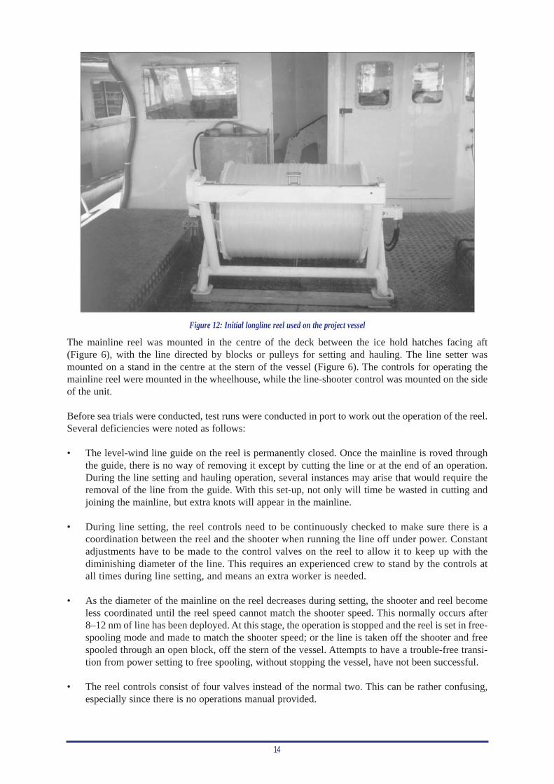
2.1.11 Mainline reel and line shooter
The mainline reel on board F/V Ulimasao at the time of launching (Figure 12) was designed and builtby Grant McCleary of Australian Mooring Service. This reel could hold up to 20 nm of 3.5 mmmonofilament line, and was hooked up to a hydraulic system driven by a Vickers VTM Series 42 06GPM pump. The line shooter on board was designed and manufactured by the Power Steering andHydraulics Company of Tauranga, New Zealand.
14
Figure 12: Initial longline reel used on the project vessel
The mainline reel was mounted in the centre of the deck between the ice hold hatches facing aft(Figure 6), with the line directed by blocks or pulleys for setting and hauling. The line setter wasmounted on a stand in the centre at the stern of the vessel (Figure 6). The controls for operating themainline reel were mounted in the wheelhouse, while the line-shooter control was mounted on the sideof the unit.
Before sea trials were conducted, test runs were conducted in port to work out the operation of the reel.Several deficiencies were noted as follows:
• The level-wind line guide on the reel is permanently closed. Once the mainline is roved throughthe guide, there is no way of removing it except by cutting the line or at the end of an operation.During the line setting and hauling operation, several instances may arise that would require theremoval of the line from the guide. With this set-up, not only will time be wasted in cutting andjoining the mainline, but extra knots will appear in the mainline.
• During line setting, the reel controls need to be continuously checked to make sure there is acoordination between the reel and the shooter when running the line off under power. Constantadjustments have to be made to the control valves on the reel to allow it to keep up with thediminishing diameter of the line. This requires an experienced crew to stand by the controls atall times during line setting, and means an extra worker is needed.
• As the diameter of the mainline on the reel decreases during setting, the shooter and reel becomeless coordinated until the reel speed cannot match the shooter speed. This normally occurs after8–12 nm of line has been deployed. At this stage, the operation is stopped and the reel is set in free-spooling mode and made to match the shooter speed; or the line is taken off the shooter and freespooled through an open block, off the stern of the vessel. Attempts to have a trouble-free transi-tion from power setting to free spooling, without stopping the vessel, have not been successful.
• The reel controls consist of four valves instead of the normal two. This can be rather confusing,especially since there is no operations manual provided.
15
2.1.12 Hauling station
The set up of the hauling station is similar to that of other locally built alias. In order to reduce costs,the wheelhouse and navigation area is also used as the hauling station. The operator therefore, is locatedin the wheelhouse, while the crew, who are unsnapping and retrieving branchlines, are situated just out-side the aft wheelhouse bulkhead. The only addition to the wheelhouse gear is the main control for thelongline reel and an overhead retractable beam to which the hauling block is connected. The haulingblock beam can be safely stored away after operations and extended into position when needed.
In the wheelhouse, the operator’s seat can be adjusted to face towards the starboard side so thatthe operator can face directly towards the hauling block. The steering wheel is in a forward-facing position. The operator can watch the hauling operation through a full-length open win-dow on hinges that is drawn upward by a string and lashed open.
2.2 Work completed on the project vessel after launching and modifications during sea trials
Although the vessel was officially launched on 6 April 2000, there was still work to be completed bythe designer consultant and the boat builder. Even three weeks after the launching date there was stillwork to be completed, although the consultant had to return to Norway.
2.2.1 Work completed before the first fishing trip
Upon arrival in Samoa on 26 April 2000, the SPC Fisheries Development Officer and the boat builderprepared the vessel for its maiden fishing trip. Several installations and adjustments were made beforethe vessel was finally ready.
• A Taiyo ADDF direction-finder receiving and antenna unit was installed. A one-metre antennastand was erected on the cabin roof, directly above the equipment console in the wheelhouse andon the starboard side of the main mast. The receiver unit was installed on the equipment consoleand a protected co-axial cable connected between the receiver and the antenna. The power cablefor the receiver was connected to the main switch for the navigation and compass lights.
Care was taken to ensure that the antenna poles were facing in the right direction and that the co-axial cable connected the right poles in the antenna with its counterpart terminals in the receiver.Tests conducted on the equipment recorded a 20° deviation to port, so a 20° starboard correctionwas made on the direction-finder azimuth (adjustment dial in degrees). The deviation was causedby the antenna stand being deflected to port when the bed was welded. Re-welding the stand bedin the fore and aft line can reset this error, although it is much easier to allow for the error on thedirection-finder azimuth.
• Two branchline bins were constructed so that each could contain up to 500 branchlines. Meanwhilebranchlines were constructed to a length of 15 m and floatlines to a length of 30 m. Two new radiobeacons were pieced together and made ready for use. Twenty nautical miles of 3.5 mm monofil-ament mainline were wound onto the mainline reel.
• All power switches on board were traced and marked according to the functions performed.
• Fire extinguishers, first aid kit, safety and sea survival gear were installed.
• The ship’s compass was installed on the equipment console, a slight distance away from the foreand aft vision of the helmsman. The reason for this was that the radar and GPS were previouslyplaced in front of the helmsman, leaving no extra length on the power cables to relocate them.Having the compass placed in the current position did not pose any difficulties or inconveniencefor the helmsman. The power line for the compass light was branched off the switch for the navi-gation lights.
16
• A marine AM/FM radio and cassette player was installed above the equipment console, forward ofthe helmsman position, with the antenna installed on the starboard side, aft of the retractable haul-ing-block beam. One speaker was installed on the outside bulkhead of the wheelhouse in the afterdeck, while the other speaker was mounted next to the radio itself. The power line for this equip-ment was doubled with the switch for the fore and aft hauling lights.
• A forward deck-light and a portable search-light outlet were positioned in the fore deck of the vessel.The power cable was doubled to the GPS switch on the main switchboard.
• A plywood storage box was fitted into the space between the port and starboard bunks. This servedas the main storage area for all fishing gear and loose tools.
• The line shooter was repositioned to the centre line of the vessel so that it could be in direct linewith the mainline reel. Denso tape (greased tape) was applied to all exposed fittings on the lineshooter and the mainline reel.
• The operator’s seat was repositioned to allow ease of movement while carrying out the fishingoperations.
• Further work was required to install the main hauling-block adjustable beam and the lugs for therelay blocks, in convenient positions that would supplement the hauling and setting operations.
• An MOT (Ministry of Transport) survey was conducted that certified the vessel seaworthy andready for trials.
2.2.2 Modifications and adjustments made during fishing trials
There were modifications and adjustments made to the project vessel during the course of the trials.These were done mainly to keep the trials alive and to ease the operations without holding up thevessel. A major set back was the failure of the mainline reel to maintain its sturdiness after only twosets, thus preventing further fishing until repairs had been done. Modifications and adjustments madeduring the course of the trials included:
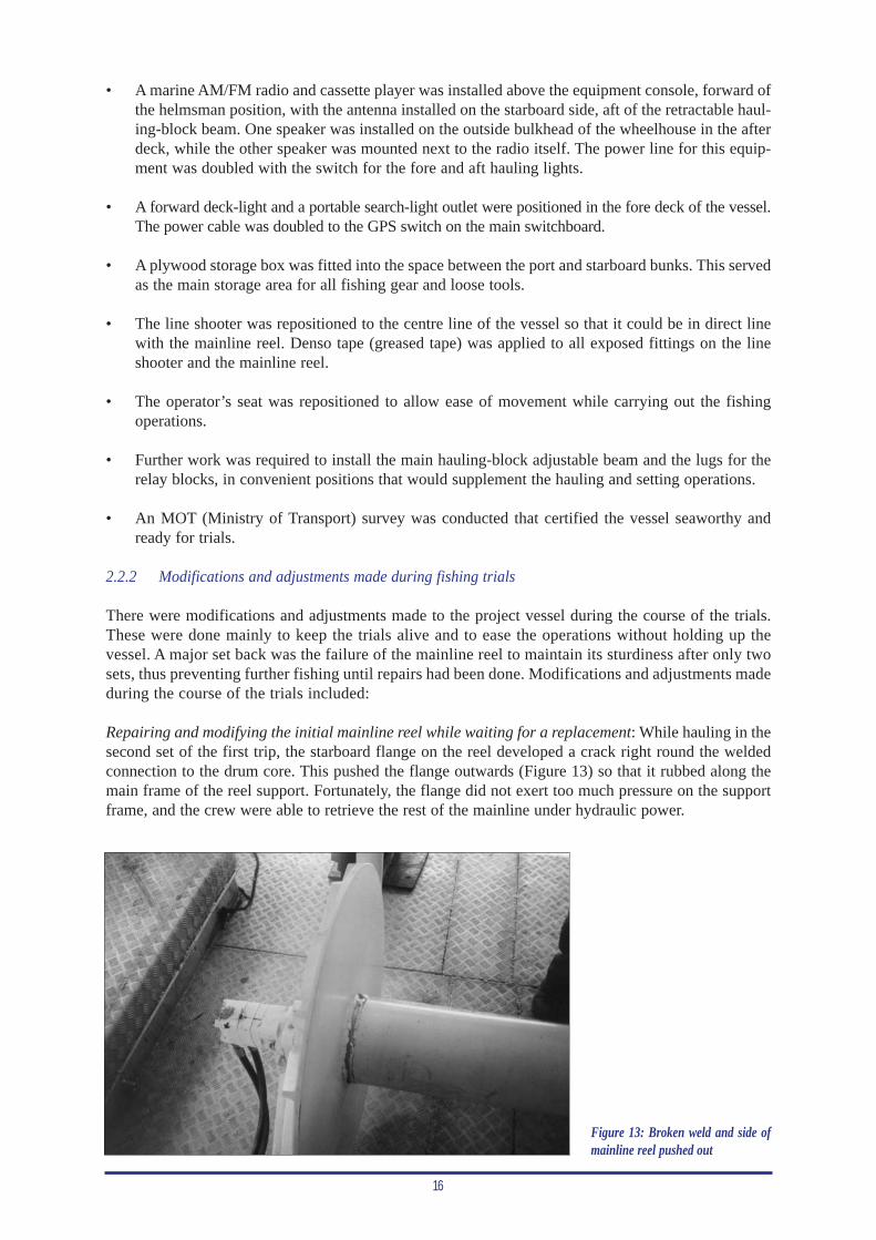
Repairing and modifying the initial mainline reel while waiting for a replacement: While hauling in thesecond set of the first trip, the starboard flange on the reel developed a crack right round the weldedconnection to the drum core. This pushed the flange outwards (Figure 13) so that it rubbed along themain frame of the reel support. Fortunately, the flange did not exert too much pressure on the supportframe, and the crew were able to retrieve the rest of the mainline under hydraulic power.
Figure 13: Broken weld and side ofmainline reel pushed out
17
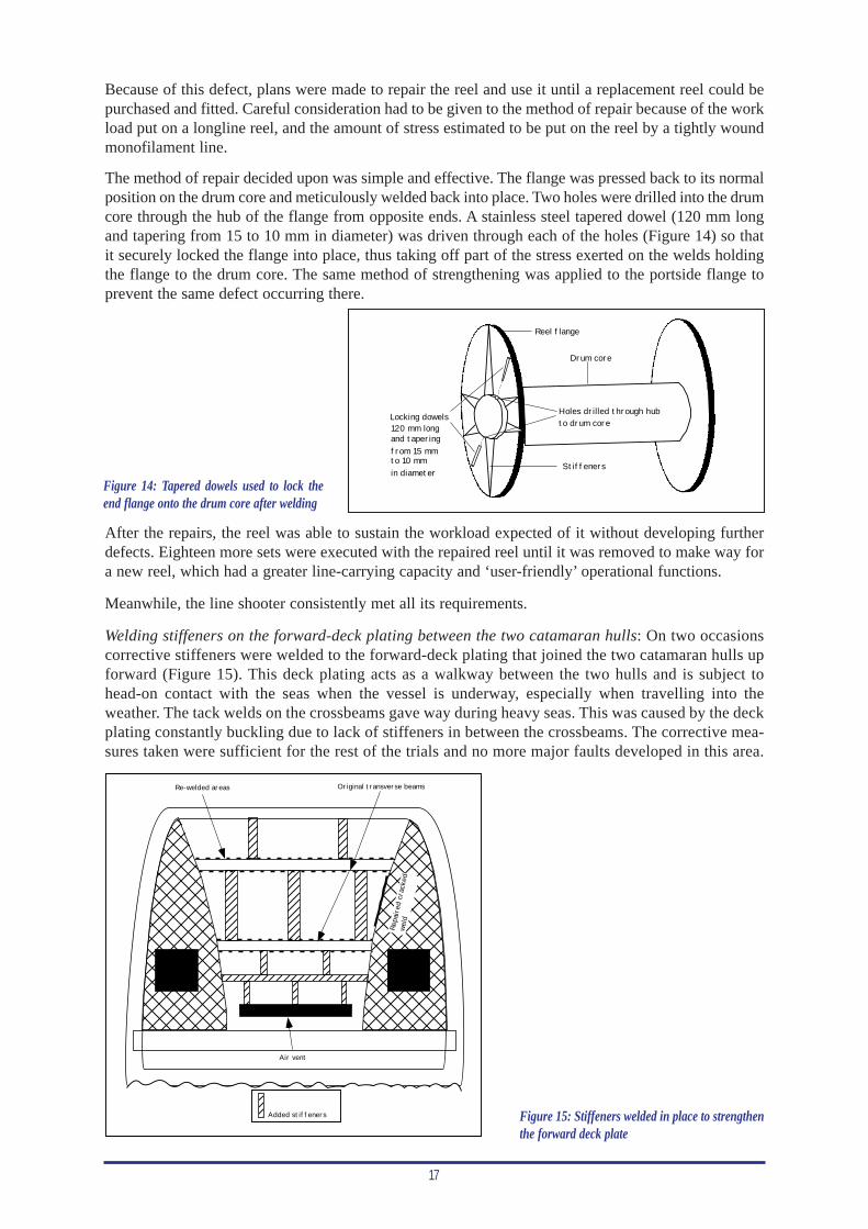
Because of this defect, plans were made to repair the reel and use it until a replacement reel could bepurchased and fitted. Careful consideration had to be given to the method of repair because of the workload put on a longline reel, and the amount of stress estimated to be put on the reel by a tightly woundmonofilament line.
The method of repair decided upon was simple and effective. The flange was pressed back to its normalposition on the drum core and meticulously welded back into place. Two holes were drilled into the drumcore through the hub of the flange from opposite ends. A stainless steel tapered dowel (120 mm longand tapering from 15 to 10 mm in diameter) was driven through each of the holes (Figure 14) so thatit securely locked the flange into place, thus taking off part of the stress exerted on the welds holdingthe flange to the drum core. The same method of strengthening was applied to the portside flange toprevent the same defect occurring there.
Reel flange
Locking dowels120 mm longand tapering
in diameter
from 15 mmto 10 mm
Drum core
Holes drilled through hubto drum core
Stiffeners
Figure 14: Tapered dowels used to lock theend flange onto the drum core after welding
After the repairs, the reel was able to sustain the workload expected of it without developing furtherdefects. Eighteen more sets were executed with the repaired reel until it was removed to make way fora new reel, which had a greater line-carrying capacity and ‘user-friendly’ operational functions.
Meanwhile, the line shooter consistently met all its requirements.
Welding stiffeners on the forward-deck plating between the two catamaran hulls: On two occasionscorrective stiffeners were welded to the forward-deck plating that joined the two catamaran hulls upforward (Figure 15). This deck plating acts as a walkway between the two hulls and is subject tohead-on contact with the seas when the vessel is underway, especially when travelling into theweather. The tack welds on the crossbeams gave way during heavy seas. This was caused by the deckplating constantly buckling due to lack of stiffeners in between the crossbeams. The corrective mea-sures taken were sufficient for the rest of the trials and no more major faults developed in this area.
Hat
ch
Hat
ch
Repa
ired
cra
cked
weld
Re-welded areas Original transverse beams
Air vent
Added stiffeners Figure 15: Stiffeners welded in place to strengthenthe forward deck plate
18
Welding handrail to the overhead deck at the starboard working area: This handrail enabled the crewto move safely around the after deck during heavy seas.
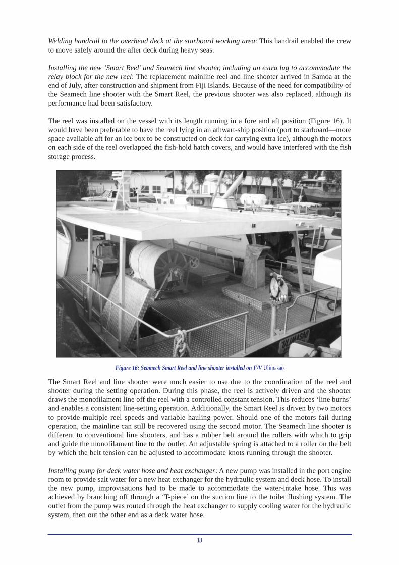
Installing the new ‘Smart Reel’ and Seamech line shooter, including an extra lug to accommodate therelay block for the new reel: The replacement mainline reel and line shooter arrived in Samoa at theend of July, after construction and shipment from Fiji Islands. Because of the need for compatibility ofthe Seamech line shooter with the Smart Reel, the previous shooter was also replaced, although itsperformance had been satisfactory.
The reel was installed on the vessel with its length running in a fore and aft position (Figure 16). Itwould have been preferable to have the reel lying in an athwart-ship position (port to starboard—morespace available aft for an ice box to be constructed on deck for carrying extra ice), although the motorson each side of the reel overlapped the fish-hold hatch covers, and would have interfered with the fishstorage process.
The Smart Reel and line shooter were much easier to use due to the coordination of the reel andshooter during the setting operation. During this phase, the reel is actively driven and the shooterdraws the monofilament line off the reel with a controlled constant tension. This reduces ‘line burns’and enables a consistent line-setting operation. Additionally, the Smart Reel is driven by two motorsto provide multiple reel speeds and variable hauling power. Should one of the motors fail duringoperation, the mainline can still be recovered using the second motor. The Seamech line shooter isdifferent to conventional line shooters, and has a rubber belt around the rollers with which to gripand guide the monofilament line to the outlet. An adjustable spring is attached to a roller on the beltby which the belt tension can be adjusted to accommodate knots running through the shooter.
Installing pump for deck water hose and heat exchanger: A new pump was installed in the port engineroom to provide salt water for a new heat exchanger for the hydraulic system and deck hose. To installthe new pump, improvisations had to be made to accommodate the water-intake hose. This wasachieved by branching off through a ‘T-piece’ on the suction line to the toilet flushing system. Theoutlet from the pump was routed through the heat exchanger to supply cooling water for the hydraulicsystem, then out the other end as a deck water hose.
Figure 16: Seamech Smart Reel and line shooter installed on F/V Ulimasao
19
The pump is belt driven and is connected to a pulley coupled to the shaft between the hydraulic pumpand the main engine. A link belt is used to connect the two pulleys during fishing operations and isdisconnected when the vessel steams to and from fishing grounds. The maximum engine speed forrunning the pump is 2,200 RPM. This allows a smooth flow without the pump sucking air and thuscausing friction on the rubber impeller.
2.3 Temperature/depth recording (TDR) equipment used on the project vessel
TDRs consist of a data logger and an interface unit. The data loggers are small microprocessor-controlled units that store data on temperature and depth over time to an erasable and program-mable read-only memory chip (Anon, 1999). The interface unit is used to set the parameters ofeach logger (temperature and depth range), the time interval that the data is recorded, and thedownloading or transfer of the data collected to a computer with the appropriate software, whichcomes with the equipment.
Close observation of the TDRs, in relation to the position along the line at which a fish is caught, cancontribute tremendously to a fisherman’s understanding of fish depth and desired temperature zone,and may help in deciding the depth at which to set the line, and increasing the catch rate.
The depth of the line will depend on the preferred temperature zone of the target species. If the depthrecorded shows a temperature range not suitable for tuna fishing, the line-setting procedure can bechanged by slowing down or speeding up the line shooter, the vessel, or both; by increasing or decreas-ing the number of hooks between floats; or by lengthening or shortening the floatlines.
During this project, each of the loggers was fitted by means of a one-metre monofilament line attachedwith a longline snap at the end. This is snapped onto the mainline as the line is deployed. Normally thecentre position between floats is sought, as this should give the fisherman a better idea of how deep theline has actually gone in that section, and any changes in depth that have occurred as a result of currentsor possibly fish on the line.
Before attaching or deploying TDRs, an initialisation process must be carried out. The activationtime interval for the logger to record data, depth range and temperature range is recorded into eachlogger. This is done by plugging each logger into the Minilog computer interface unit and setting theparameters through the Minilog software programme on the computer used.
After use, the information is downloaded onto the main programme via the Minilog interface unit andan evaluation of the deployment can then be retrieved. The information is depicted in graph form, witha summary table attached.
In order to use the TDR equipment on board, a computer with appropriate software and the interfaceunit needs to be carried on each trip. The loggers can be set for a period of time that covers the wholetrip, or the data can be downloaded after every set is hauled up. For fishing purposes, downloading afterevery haul will enable fishermen to assess how the previous set has gone and adjust the gear for thenext set accordingly.
3. PROJECT ACTIVITIES, ON-BOARD TRAINING AND CATCH RESULTS
This project was originally scheduled to run for three months in Samoa. However, because of problemsencountered with the original mainline reel, and the subsequent repairs and replacement with a newmainline reel, the Fisheries Division in Samoa requested an extension to the project. This was grantedand the project was extended by six weeks.
During the project, a total of 30 longline sets were made during 11 fishing trips on board F/VUlimasao. During this time, some modifications and adjustments were made to the vessel and fishinggear as outlined in Section 2 above.
20
As this was a new vessel, the skipper and crew were also learning about the boat and gear. To assist theskipper settle into a standard routine, the Fisheries Development Office developed a set of proceduresto be followed for the starting of the main engines prior to departure on each trip. This included thechecking of all oil levels and topping up when necessary. The main engine-starting procedures to befollowed are listed in Appendix B.
3.1 Selection of fishing grounds
The selection of fishing grounds during the trials initially depended on information provided by otherfishermen and careful observation of the catches that were landed. After the first trip, the approach wasto go to the spot where fish were caught on the last set, and use this as a rough starting point. Duringhauling, a careful record was kept of where fish were caught along the line. The next set would bestarted around the area of greatest catch. If the catch for a trip was poor, the next trip would bestarted in a new area based on features taken from the chart and reports from other fishermen.
When starting in a new location, fishing grounds can be selected through a process of elimination todetermine the more preferable areas. Firstly, navigation charts for the new location would be carefullyappraised. Other factors to take into account include the position and depth of seamounts; layout ofunderwater contours and the depth at which the slope recedes, especially from the 1,000 m contour todeeper waters; and knowledge of the currents.
Other information essential for locating fish is the depth of the thermocline and the seawater tempera-ture. With this knowledge, it is possible to determine areas of upwelling. Fish normally congregatearound upwellings if the water temperature in the region is suitable. With modern equipment, seawatertemperature and thermocline depths can be determined. Satellite information can be obtained to showthe SST (sea surface temperatures) within the region of operation but the fisherman in many cases hasto subscribe and pay to obtain this service or information (http://www.ccar.colorado.edu andhttp://www.cls.fr).
The Internet (http://www.vemco.com) gives free information on sea-surface height anomaly (altimetricmaps) that is as good as the SST information. This shows the height of the sea level at different tem-perature zones. Warmer water has a higher height figure compared to cold water areas (Beverly, 2000).A fisherman may need to seek assistance from someone who has previously worked with SST charts oraltimetric maps to be able to fully evaluate the information presented in them.
Altimetric maps were used for the last three fishing trips of the project visit, with good catchesrecorded on two of these trips. No conclusions were drawn based on the limited use of these maps,however, greater understanding of the information should lead to better catches.
3.2 Fishing gear and method
The fishing gear and method were consistent throughout the project fishing trials. However, effort didincrease during the project once the mainline reel was replaced. With the original mainline reel,700–800 hooks were used per set. These increased to 1,100–1,200 hooks per set with the new, larger-capacity reel.
3.2.1 Gear used
The fishing gear on board F/V Ulimasao with the new mainline reel consisted of 1,500 branchlines,50 floats, five larger inflatable buoys, 50 floatlines, four strobe lights, two radio beacons, and spare snaps,hooks, crimps and 2.2 mm monofilament line. The mainline reel held 30 nm of 3.5 mm monofilament line.
The branchlines were made from 15 m of 2.2 mm monofilament line with a size 3.4 Japanese tuna hookcrimped on to one end, and a 0.148 snap with 9/0 swivel crimped on to the other end. The branchlineswere stored in three branchline bins, 500 in each. Observations have shown that longer branchlines ofbetween 10 to 20 m in length result in more live fish being landed than shorter branchlines of less than10 m in length. Therefore, preference was given to constructing branchlines of 15 m.
21
The floatlines were rigged from 30 m of 6 mm polypropylene rope with a Japanese floatline snapspliced into one end and a 15 cm open-eye spliced into the other. Negatively buoyant rope would havebeen better for the floatlines; however, this was not available at the time.
The floats were 300 mm diameter hard plastic longline floats. Each float had a 0.5 m by 6 mmpolypropylene line spliced into the float handle, with a Japanese longline snap spliced into the otherend. One radio beacon had a strobe light attached, with the remaining three strobe lights screwed intolongline floats with the appropriate connection. All strobe lights were activated by a photo-sensitivecell. The larger inflatable buoys were of the Polyform A-series type, around 60 cm in diameter.
3.2.2 Method used
F/V Ulimasao has its working deck aft (Figures 16 and 17). Hauling is carried out from the starboardside. The vessel is steered from the wheelhouse, where the engine controls and the controls for operatingthe mainline reel are also installed.
For tuna longline fishing, the line setting operation is very important. The method of setting the lineaffects catch results and the length of time it takes to haul the line in. Before setting the line, severalfactors have to be considered that make hauling easier. These include the choice of fishing grounds,wind direction, position of the wind during setting and its relative position when hauling the line backin, direction of current, sea state, number of hooks between floats and the method in which the snapsare attached to the mainline.
Since F/V Ulimasao is a starboard-hauling vessel, it would be appropriate to have the wind straightahead or fine on the starboard bow when hauling the line back in. This would allow the vessel to driftoff the mainline when the vessel stops for gaffing fish or for any other reason. With the wind fine onthe starboard bow, it would be easier for the vessel operator to manoeuvre the vessel during linehauling. There will also be less engaging and disengaging of the engine clutch, therefore less wearand tear on the gearbox. In order to increase the possibility of having the wind on the starboard bowwhen hauling the line back in, the wind should be placed on the port quarter when setting the line.
Line setting is conducted at a speed of around 6–7 knots, or 2,200 RPM on both engines. This allowsthe person baiting the hook sufficient time to remove the branchline from the bin, bait it and snap it onthe mainline, and still maintain a consistent distance of 30 to 50 m between hooks. Two methods of linesetting were used during the trials. One method free-spooled the line off the stern of the vessel througha block; the other used a line shooter. Using the line shooter is preferred, as it allows greater controlover the positioning of the gear at the desired depth. Figure 17 shows the arrangement onF/V Ulimasao, when the line shooter is used for setting.
FloatlinesLine shooter
Bait box
Relay block Main haulingblock
Branchlinebin
Floats
Mainline
Work area forperson baiting andattaching branchlinesto mainline
Figure 17: Setting arrangement when using the line shooter on F/V Ulimasao
22
Several numbers of hooks per basket were tried; 30 hooks between floats achieved better results, so thisnumber was used in most sets. Whenever possible, setting was done across current or at an angle ofabout 20° to the current. This allowed the line to be trolled down current during the soaking process.
Setting was mostly begun after daybreak (0530 to 0630 hours). This was to prevent the sardine baitfrom being eaten overnight by undesirable species. Another reason was to allow the crew to observeclearly how the line is deployed and avoid the dangers of handling unfamiliar gear under artificial light.The duration of setting times varied from 3–3.5 hours, depending on vessel speed and on method ofline setting.
When the line shooter was used for setting, the shooter speed was kept at 280 RPM. This achieveddepths from 180 to 450 m as measured by the temperature/depth recorders. Setting the line at 320 RPMon the line shooter resulted in the mainline reaching 600 m in some places, which was too deep for fasthauling, as a lot of stress was put on the line. Fewer hooks were deployed with the faster setting speedas the space between hooks would be around 50 to 70 m in some places. This is because the crew cannot to keep up with the faster rate of deploying the line and are unable to maintain a consistent rate ofattaching branchlines to the mainline.
If a faster setting speed is required, this can be achieved by using two branchline bins and two crew tosnap the branchlines to the mainline. The line-shooter speed and snap-on time can be calculated so thata consistent distance can be maintained between branchlines. Faster boat speed will require a fasterline-shooter speed and a shorter period between ‘snap-ons’. For the purpose of these trials, the first set-ting method was sufficient for training.
It takes a crew approximately 7 to 10 seconds to unhitch, bait and attach the branchline to the main-line. At 280 RPM the crew is able to maintain a spacing of between 30 to 50 m, which, with 30 hooksper basket, will allow the line to settle at a suitable soaking depth.
Attaching the branchlines to the mainline is done in a left-to-right motion, with the clip in an invertedposition. This will allow the person unsnapping the branchlines to do so with a downward movement,which is quicker and puts less strain on the hands.
For line hauling, one person steered the vessel and controlled the mainline reel from the cabin. Twocrew were stationed outside the cabin. The first unsnapped the branchlines from the mainline as theycame up to the main hauling block. This crew then passed the branchline snap to the second crew, whoconnected the snap to the bin and pulled the branchline into the bin for storage. The mainline contin-ued around the main hauling block to the relay block, then onto the mainline reel (Figure 18).
Floatlines
Shooter
Bait box
Landing portfor fish
Relay block Person storingbranchlinesin bin
Retractable arm withmain hauling block
Mainline
Branchlinebin
Person unsnappingbranchlines
Floats
Figure 18: Hauling arrangement on F/V Ulimasao
23
A set of procedures was developed for both the line setting and line hauling operations by the FisheriesDevelopment Officer. These procedures were followed prior to and during the operations, as a check-list for the skipper and crew. These procedures are presented in Appendix C.
3.2.3 Management of working space
The project vessel has ample working space for both the setting and hauling operation. Because thevessel is a catamaran design, a continuous deck joins both hulls. Management of the working area isimportant for ease of operations.
During line setting, only one branchline bin is used at a time. This is situated aft on the starboard side(Figure 17). The second bin is placed on the portside in readiness for changeover when the first bin runsout or in times of branchline tangles. The float deployment is done on the port quarter area. An ice chestis placed aft of the reel to hold the cases of bait to be used during the set. Small portions of around 50 baitsat a time are transferred to the bait box. This ensures that the bait remains fresh until it is hooked on.
The rest of the working area is kept clear of obstacles to enable better manoeuvrability during linesetting. Both engine hatches are kept clear for easy access when required.
For the hauling operation, a branchline bin is placed aft of the wheelhouse next to the hauling block(Figure 18). This enables the person who is unsnapping the branchlines and the person storing thebranchlines to be within arm’s reach of each other. As soon as a branchline bin is filled, it is immediatelytransferred aft. All the gear retrieved during hauling is placed in strategic positions on the vessel in prepa-ration for line setting the next morning.
The fish-processing area was set up on the deck abaft the reel next to the shooter. This location is clearfrom all obstacles and allows the crew plenty of room to process fish.
3.2.4 Fish preparation and icing
Being experienced fishermen, most of the work done on F/V Ulimasao was not new to the crew andthe trials served as a refresher period for them.
When boating a fish, the person gaffing must alwaysensure that the fish is gaffed through the head(Figure 19). This ensures that the flesh of the fish iskept intact allowing less chance for bacteria to enterthe flesh and spoil the fish. In addition, most marketsprefer fish that look whole rather than those marked inappearance.
The fish-processing method used by the crew is stan-dard practice for fresh fish supplied to the Japanesesashimi market. Upon boating a live fish, it isimmediately stunned with a fish bat, bled andspiked, and the tanaguchi method applied (a neat holeis cut around the soft spot on the head and a 3.5 mmmonofilament line is inserted through the hole, anddown the neural canal along the backbone of the fish(Blanc, 1996)). Sometimes the live fish is bled afterhas been stunned, spiked and the tanaguchi methodhas been applied. Fish that are dead when boated areonly bled. The bleeding points on the fish are along thelateral line about a palm’s width (around 10 cm) fromthe pectoral fin. A cut about 25 mm long and 25 mmdeep is made on both sides of the fish across the lateralline at the bleeding points. The next bleeding points areon both sides of the tail around the fourth or fifth finlet.Figure 19: Fish gaffed in the head for boating
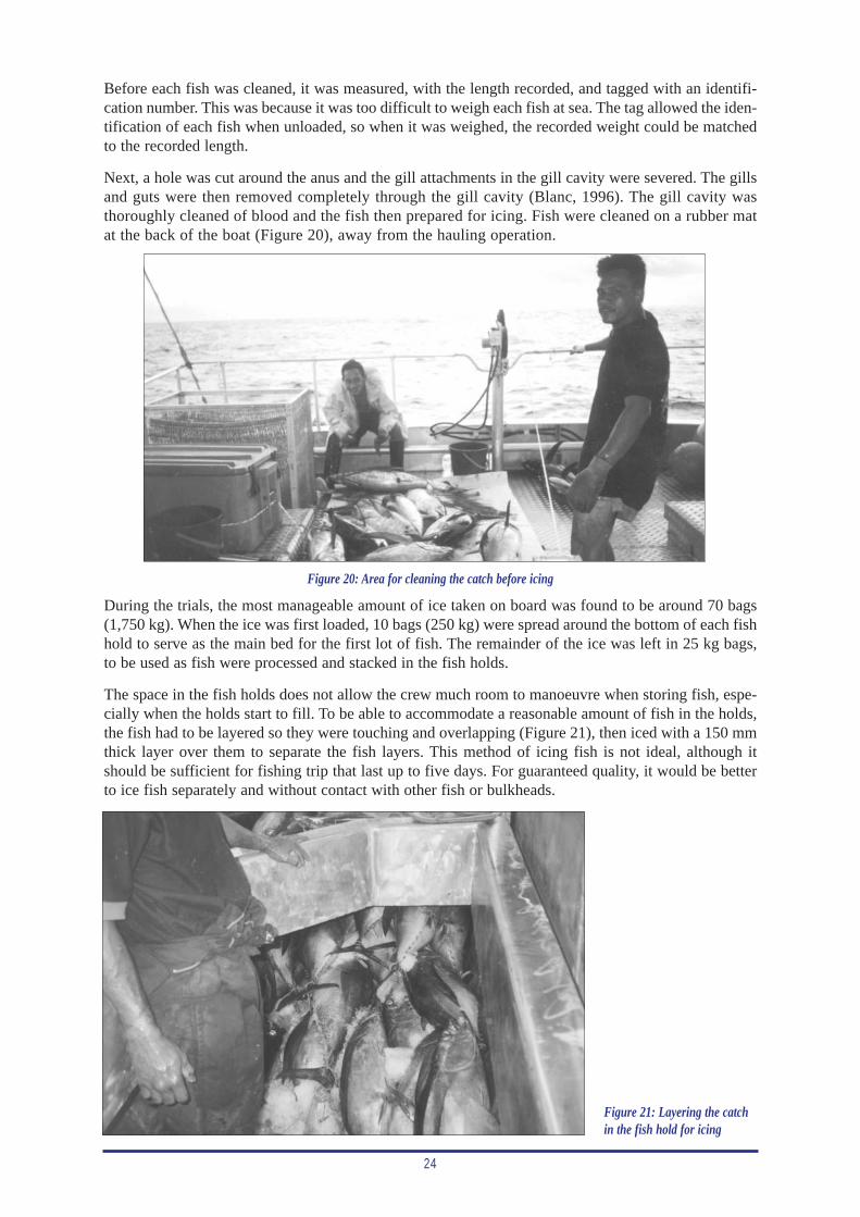
24
Before each fish was cleaned, it was measured, with the length recorded, and tagged with an identifi-cation number. This was because it was too difficult to weigh each fish at sea. The tag allowed the iden-tification of each fish when unloaded, so when it was weighed, the recorded weight could be matchedto the recorded length.
Next, a hole was cut around the anus and the gill attachments in the gill cavity were severed. The gillsand guts were then removed completely through the gill cavity (Blanc, 1996). The gill cavity wasthoroughly cleaned of blood and the fish then prepared for icing. Fish were cleaned on a rubber matat the back of the boat (Figure 20), away from the hauling operation.
During the trials, the most manageable amount of ice taken on board was found to be around 70 bags(1,750 kg). When the ice was first loaded, 10 bags (250 kg) were spread around the bottom of each fishhold to serve as the main bed for the first lot of fish. The remainder of the ice was left in 25 kg bags,to be used as fish were processed and stacked in the fish holds.
The space in the fish holds does not allow the crew much room to manoeuvre when storing fish, espe-cially when the holds start to fill. To be able to accommodate a reasonable amount of fish in the holds,the fish had to be layered so they were touching and overlapping (Figure 21), then iced with a 150 mmthick layer over them to separate the fish layers. This method of icing fish is not ideal, although itshould be sufficient for fishing trip that last up to five days. For guaranteed quality, it would be betterto ice fish separately and without contact with other fish or bulkheads.
Figure 20: Area for cleaning the catch before icing
Figure 21: Layering the catchin the fish hold for icing
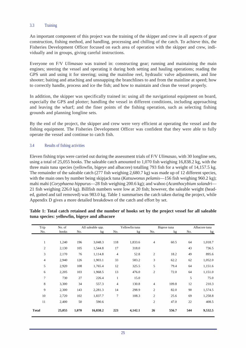
25
3.3 Training
An important component of this project was the training of the skipper and crew in all aspects of gearconstruction, fishing method, and handling, processing and chilling of the catch. To achieve this, theFisheries Development Officer focused on each area of operation with the skipper and crew, indi-vidually and in groups, giving careful instructions.
Everyone on F/V Ulimasao was trained in: constructing gear; running and maintaining the mainengines; steering the vessel and operating it during both setting and hauling operations; reading theGPS unit and using it for steering; using the mainline reel, hydraulic valve adjustments, and lineshooter; baiting and attaching and unsnapping the branchlines to and from the mainline at speed; howto correctly handle, process and ice the fish; and how to maintain and clean the vessel properly.
In addition, the skipper was specifically trained in: using all the navigational equipment on board,especially the GPS and plotter; handling the vessel in different conditions, including approachingand leaving the wharf; and the finer points of the fishing operation, such as selecting fishinggrounds and planning longline sets.
By the end of the project, the skipper and crew were very efficient at operating the vessel and thefishing equipment. The Fisheries Development Officer was confident that they were able to fullyoperate the vessel and continue to catch fish.
3.4 Results of fishing activities
Eleven fishing trips were carried out during the assessment trials of F/V Ulimasao, with 30 longline sets,using a total of 25,055 hooks. The saleable catch amounted to 1,070 fish weighing 16,838.2 kg, with thethree main tuna species (yellowfin, bigeye and albacore) totalling 793 fish for a weight of 14,157.5 kg.The remainder of the saleable catch (277 fish weighing 2,680.7 kg) was made up of 12 different species,with the main ones by number being skipjack tuna (Katsuwonus pelamis—156 fish weighing 960.2 kg);mahi mahi (Coryphaena hippurus—28 fish weighing 200.6 kg); and wahoo (Acanthocybium solandri—21 fish weighing 226.0 kg). Billfish numbers were low at 20 fish; however, the saleable weight (head-ed, gutted and tail removed) was 983.0 kg. Table 1 summarises the catch taken during the project, whileAppendix D gives a more detailed breakdown of the catch and effort by set.
Table 1: Total catch retained and the number of hooks set by the project vessel for all saleabletuna species: yellowfin, bigeye and albacore
Trip No. ofNo. hooks No. kg No. kg No. kg No. kg
1 1,240 196 3,048.3 118 1,833.6 4 60.5 64 1,018.7
2 2,130 105 1,544.8 17 318.0 43 736.5
3 2,170 76 1,114.8 4 52.8 2 18.2 49 895.6
4 2,940 126 1,903.1 33 583.2 3 62.2 62 1,052.0
5 2,920 108 1,765.4 12 325.5 5 79.4 64 1,151.6
6 2,205 103 1,968.5 13 476.0 2 72.0 64 1,151.0
7 730 27 226.4 1 15.0 5 75.0
8 3,300 34 557.3 4 130.8 4 109.8 12 210.3
9 2,300 143 2,281.3 14 298.9 2 82.0 90 1,574.5
10 2,720 102 1,837.7 7 108.3 2 25.6 69 1,258.8
11 2,400 50 590.6 2 47.0 22 408.5
Total 25,055 1,070 16,838.2 223 4,142.1 26 556.7 544 9,532.5
All saleable spp. Yellowfin tuna Bigeye tuna Albacore tuna
26
Of the eleven trips, trip number seven was aborted so that the vessel could return to have the new reelinstalled, with only one set completed. On trip eight, pilot whales ate most of the fish and 90 per centof the bait on the line for three consecutive sets. This resulted in very few tuna being landed (20 tunaweighing 450.9 kg). The number and size of the fish heads on the line indicated the catch should havebeen around four times more than was landed.
Table 2 summarises the catch per unit of effort (CPUE) for the main tuna species, with the species com-position of the total catch provided in Appendix E. The overall CPUE for saleable species was 67.2kg/100 hooks, although the CPUE on a per-trip basis varied from a low of 16.9 kg/100 hooks (trip 8),to a high of 245.8 kg/100 hooks (trip 1). Albacore tuna was the most predominant species (544 fishweighing 9,532.5 kg), with an overall CPUE of 38.1 kg/100 hooks. Yellowfin tuna was the second mostcommon species (223 fish weighing 4,142.1 kg), with an overall CPUE of 16.5 kg/100 hooks.
Table 2: CPUE, percentage of catch and average weight (gilled and gutted) for all saleable species(All sale) yellowfin tuna (YFT), bigeye tuna (BET) and albacore tuna (ALB)
TripNo. All sale YFT BET ALB YFT BET ALB YFT BET ALB
1 245.83 147.87 4.88 82.15 60.15 1.98 33.42 15.54 15.13 15.92
2 72.53 14.93 0.00 34.58 20.59 0.00 47.68 18.71 0.00 17.13
3 51.37 2.43 0.84 41.27 4.74 1.63 80.34 13.20 9.10 18.28
4 64.73 19.84 2.12 35.78 30.64 3.27 55.28 17.67 20.73 16.97
5 60.46 11.15 2.72 39.44 18.44 4.50 65.23 27.13 15.88 17.99
6 89.27 21.59 3.27 52.20 24.18 3.66 58.47 36.62 36.00 17.98
7 31.01 2.05 0.00 10.27 6.63 0.00 33.13 15.00 0.00 15.00
8 16.89 3.96 3.33 6.37 23.47 19.70 37.74 32.70 27.45 17.53
9 99.19 13.00 3.57 68.46 13.10 3.59 69.02 21.35 41.00 17.49
10 67.56 3.98 0.94 46.28 5.89 1.39 68.50 15.47 12.80 18.24
11 24.61 0.00 1.96 17.02 0.00 7.96 69.17 0.00 23.50 18.57
Total 67.20 16.53 2.22 38.05 24.60 3.31 56.61 18.57 21.41 17.52
CPUE (kg/100 hooks) Percentage by weight Average weight
When looking at the different tuna species as a percentage of the total saleable catch, albacore was themost significant at 56.6 per cent overall, followed by yellowfin at 24.6 per cent. The bigeye catch waslow at 3.3 per cent of the catch. The average size of both bigeye and yellowfin was small at 21.4 kgand 18.6 kg respectively, although small numbers of larger individuals were caught. For example, ontrip six, the average weight for both yellowfin and bigeye was 36 kg. The average size for albacore wasgood at 17.5 kg.
Only small numbers of unsaleable fish were taken during the project, with this component consistingof 60 fish weighing 660 kg. Nine blue sharks (Prionace glauca) and four oceanic whitetip sharks(Carcharhinus longimanus) made up the bulk of this weight (555.0 kg). Although the flesh of thesharks was not sold, it was retained for consumption by the crew. The shark fins were sold to a localbuyer.
3.5 Comparison of catch rates
It is difficult to directly compare tuna longlining catch rates between countries in the Pacific, as thespecies composition of the catch varies and some fisheries target different species. In some countriessuch as Solomon Islands and Papua New Guinea, the catch rate for yellowfin and bigeye tuna is natu-rally higher than countries like Fiji Islands, Tonga and Cook Islands. Therefore, the most appropriatecountries to compare the Samoan catch rate with are those close by with similar weather and oceano-graphic conditions, such as Fiji Islands and Tonga.
27
When looking at the catch rates for domestic tuna longliners in Fiji Islands and Tonga over recentyears (1996–2000) for the period May to August inclusive (the same fishing period as the currentproject), the overall catch rates vary between 38.8 kg/100 hooks and 68.7 kg/100 hooks for FijiIslands, and 36.4 kg/100 hooks and 52.0 kg/100 hooks in Tonga (SPC Regional Tuna FisheriesDatabase). The overall catch rate for this Samoa project of 67.2 kg/100 hooks compares veryfavourably with these catch rates. This catch rate also compares well with that obtained in Samoa in1999 (62 kg/100 hooks—Sokimi et al., 2000), although the fishing period was from October toDecember inclusive.
The percentage of the three main tuna species (yellowfin, bigeye and albacore) by weight in thecatch, also varied from year to year in both Fiji Islands and Tonga. In Fiji Islands the catch ofyellowfin and bigeye tuna combined varied from 15.7 to 27.8 per cent of the catch, while inTonga the variation was from 14.4 to 45.6 per cent of the catch over the May to August period indifferent years (1996–2000). The catch of albacore tuna varied from 40 to 68 per cent in FijiIsland and 40 to 65 per cent in Tonga over the same period. The current catch level in Samoa at27.9 per cent for yellowfin and bigeye tuna, and 56.6 per cent for albacore, fits well within theranges experienced in Fiji Islands and Tonga. So too does the catch achieved in Samoa in 1999,with 31.3 per cent of the catch being yellowfin and bigeye tuna, with albacore tuna making up55.8 per cent of the catch (Sokimi et al., 2000).
The one area where there appears to be a significant difference between the tunas in Fiji Islands andTonga compared to Samoa is in the average size (weight) of some species. In Fiji Islands, theaverage weight of yellowfin tuna ranged from 23.5 to 28.5 kg, which was considerably higherthan in the current project, at 18.6 kg, and also higher than the range in Tonga (17.8 to 19.7 kg).The average weight of bigeye tuna was similar in all three locations: in Fiji Islands the averageweight was 20.0 to 24.4 kg; in Tonga 18.8 to 23.6 kg; and in Samoa 21.4 kg. The average weightfor albacore tuna in all three locations was in the range of 16.0 to 18.0 kg.
3.6 Results from the temperature/depth recording (TDR) equipment
The use of the TDRs during the fishing trials proved to be an excellent way of determining asuitable setting speed for the vessel and the line shooter, so that the line finally settled aroundthe desired depth for fishing.
During trip one, two sets were made. The first set was made without a line shooter, with the vesselspeed at 6–7 knots. The TDRs were deployed between hook numbers 15 and 16, from the fourth sec-tion to the ninth section or basket of the full mainline. Each section or basket consisted of 30 hooksbetween floats, with a hook spacing of 30 to 50 m. The TDRs were meant to be at the centre of thesections so that the deepest depth between the floats could be measured. The shallowest sectionrecorded for set one was 193 m, while the deepest section was 350 m. Average depth for the fiveTDRs was 285 m.
Set number two was made using the line shooter at a vessel speed of 6–7 knots, and the line shooter seton 280 RPM. The shallowest depth recorded for this set was 276 m; and the deepest 582 m. Figures 22and 23 show the depths recorded on both set one (no line shooter) and two (line shooter used) on thefirst trip. On both sets, the line appears to have fluctuated considerably in its depth. This could havebeen the result of fish on the line (90 fish on 540 hooks during set one and 106 fish on 700 hooks onset two). There also appears to be a large variation in the maximum depth achieved at differentlocations along the line on set two, which could have been the result of currents at different depths.Also, TDR units may not have been positioned in the centre of the mainline between floats.
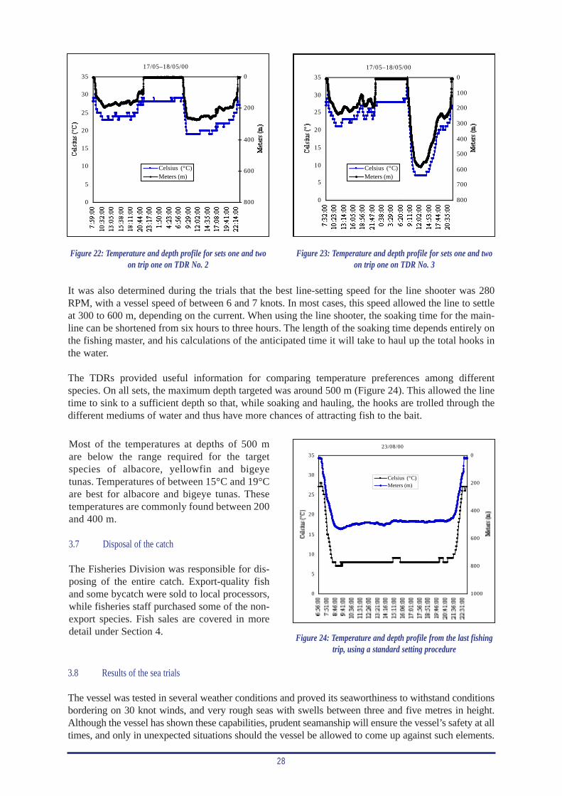
28
0
5
10
15
20
25
30
35
7:59
:00
10:3
2:00
13:0
5:00
15:3
8:00
18:1
1:00
20:4
4:00
23:1
7:00
1:50
:00
4:23
:00
6:56
:00
9:29
:00
12:0
2:00
14:3
5:00
17:0
8:00
19:4
1:00
22:1
4:00
Cel
sius
(°C
)0
200
400
600
800
17/05–18/05/00
Met
ers
(m)
Celsius (°C)Meters (m)
0
5
10
15
20
25
30
35 0
200
400
600
800
1000
23/08/00
Celsius (°C)Meters (m)
0
5
10
15
20
25
30
35 0
100
200
300
400
500
600
700
800
17/05–18/05/00
Celsius (°C)Meters (m)
Figure 22: Temperature and depth profile for sets one and twoon trip one on TDR No. 2
Figure 24: Temperature and depth profile from the last fishingtrip, using a standard setting procedure
Figure 23: Temperature and depth profile for sets one and twoon trip one on TDR No. 3
It was also determined during the trials that the best line-setting speed for the line shooter was 280RPM, with a vessel speed of between 6 and 7 knots. In most cases, this speed allowed the line to settleat 300 to 600 m, depending on the current. When using the line shooter, the soaking time for the main-line can be shortened from six hours to three hours. The length of the soaking time depends entirely onthe fishing master, and his calculations of the anticipated time it will take to haul up the total hooks inthe water.
The TDRs provided useful information for comparing temperature preferences among differentspecies. On all sets, the maximum depth targeted was around 500 m (Figure 24). This allowed the linetime to sink to a sufficient depth so that, while soaking and hauling, the hooks are trolled through thedifferent mediums of water and thus have more chances of attracting fish to the bait.
Most of the temperatures at depths of 500 mare below the range required for the targetspecies of albacore, yellowfin and bigeyetunas. Temperatures of between 15°C and 19°Care best for albacore and bigeye tunas. Thesetemperatures are commonly found between 200and 400 m.
3.7 Disposal of the catch
The Fisheries Division was responsible for dis-posing of the entire catch. Export-quality fishand some bycatch were sold to local processors,while fisheries staff purchased some of the non-export species. Fish sales are covered in moredetail under Section 4.
3.8 Results of the sea trials
The vessel was tested in several weather conditions and proved its seaworthiness to withstand conditionsbordering on 30 knot winds, and very rough seas with swells between three and five metres in height.Although the vessel has shown these capabilities, prudent seamanship will ensure the vessel’s safety at alltimes, and only in unexpected situations should the vessel be allowed to come up against such elements.

29
A point to note on the vessel’s hull construction is that when the vessel is fully underway, the hullslift and seem to skim on the sea surface. This also happens when fully loaded. During fishing oper-ations, the vessel mostly remains above the wave crests and does not ‘dig in’ as some vessels tendto do.
When travelling into head seas with swells over two metres or swells that have a short period betweenwave crests, it is advisable to reduce engine speed so that the vessel rides comfortably above the swells.Running at full steaming speed in these conditions endangers the vessel. Occasionally the odd swellswamps the forward area; this puts a lot of pressure on the cross deck and could swamp the forwardholds that are not watertight, as the hatch covers are only secured by ropes.
Additional corrective stiffeners were welded to the forward deck plating that joined the two hulls upforward on two occasions. This appeared to fix the problem of cracked welds. However, this areashould be checked after each trip to ensure no future problems occur.
4. ECONOMICS OF THE FISHING OPERATION
One of the main objectives of this project was to assess the suitability of F/V Ulimasao as a tuna long-liner for Samoan fishing conditions. To do this effectively, the economics of the fishing operationwere examined to see if the fishing operation was viable. Given that fishing was conducted over afour-month period, the catch figures were extrapolated to cover the expected fishing period of tenmonths. This is based on anecdotal information that the period from February to April is unproduc-tive for tunas, especially albacore, and reduces the fishing season of the longline fleet.
4.1 Income from fish sales
The Fisheries Division was responsible for selling all fish during the fishing trials. They sold fish tolocal processors, as well as to fisheries staff. In some cases, fish was given away to repay favours, orin the case of the first fishing trip, to meet traditional and customary obligations.
All fish were gilled and gutted at sea before chilling. When landed for sale, billfish and opah had theheads and tails removed before weighing and marketing. All other saleable species were sold in agilled and gutted form, or cut into chunks and sold to fisheries staff. Records were kept of all fishsold, with the weights and value recorded.
The purchase price paid by processors varied by species, and in some cases, such as yellowfin andbigeye tuna, by size of fish as well. The price paid for albacore tuna was consistent at WST 5.95/kg.For yellowfin and bigeye tuna, the price varied from WST 2.20/kg for small fish, WST 3.10 or4.85/kg for medium fish, and WST 7.50/kg for large fish. Broadbill swordfish sold for WST 4.40/kg(trunked), marlin for WST 2.20/kg (trunked), and opah for WST 5.95/kg (headed and gutted). Otherbycatch species sold for an average price of WST 2.20/kg. Table 3 summarises the income from fishsales for the entire project, on a per-trip basis. The total saleable catch of 16,838.2 kg had a whole-sale market value of WST 81,956.80, which gives an average price of WST 4.87/kg.
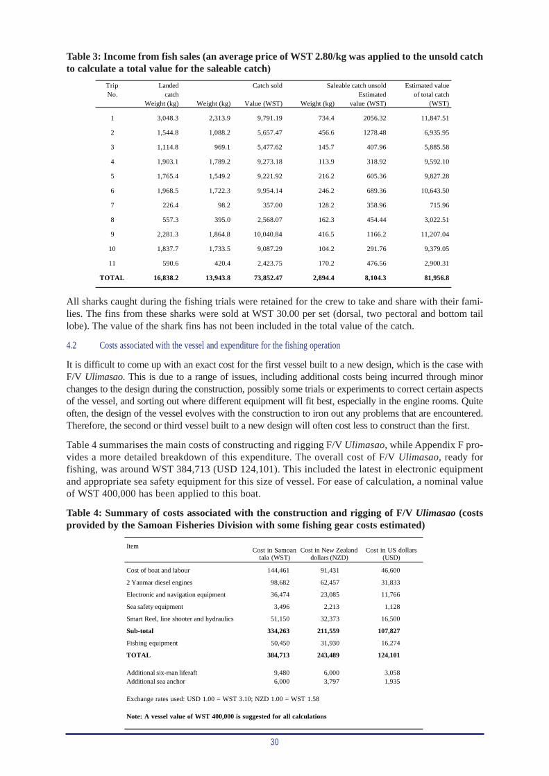
30
Trip Landed Estimated valueNo. catch Estimated of total catch
Weight (kg) Weight (kg) Value (WST) Weight (kg) value (WST) (WST)
1 3,048.3 2,313.9 9,791.19 734.4 2056.32 11,847.51
2 1,544.8 1,088.2 5,657.47 456.6 1278.48 6,935.95
3 1,114.8 969.1 5,477.62 145.7 407.96 5,885.58
4 1,903.1 1,789.2 9,273.18 113.9 318.92 9,592.10
5 1,765.4 1,549.2 9,221.92 216.2 605.36 9,827.28
6 1,968.5 1,722.3 9,954.14 246.2 689.36 10,643.50
7 226.4 98.2 357.00 128.2 358.96 715.96
8 557.3 395.0 2,568.07 162.3 454.44 3,022.51
9 2,281.3 1,864.8 10,040.84 416.5 1166.2 11,207.04
10 1,837.7 1,733.5 9,087.29 104.2 291.76 9,379.05
11 590.6 420.4 2,423.75 170.2 476.56 2,900.31
TOTAL 16,838.2 13,943.8 73,852.47 2,894.4 8,104.3 81,956.8
Catch sold Saleable catch unsold
Table 3: Income from fish sales (an average price of WST 2.80/kg was applied to the unsold catchto calculate a total value for the saleable catch)
All sharks caught during the fishing trials were retained for the crew to take and share with their fami-lies. The fins from these sharks were sold at WST 30.00 per set (dorsal, two pectoral and bottom taillobe). The value of the shark fins has not been included in the total value of the catch.
4.2 Costs associated with the vessel and expenditure for the fishing operation
It is difficult to come up with an exact cost for the first vessel built to a new design, which is the case withF/V Ulimasao. This is due to a range of issues, including additional costs being incurred through minorchanges to the design during the construction, possibly some trials or experiments to correct certain aspectsof the vessel, and sorting out where different equipment will fit best, especially in the engine rooms. Quiteoften, the design of the vessel evolves with the construction to iron out any problems that are encountered.Therefore, the second or third vessel built to a new design will often cost less to construct than the first.
Table 4 summarises the main costs of constructing and rigging F/V Ulimasao, while Appendix F pro-vides a more detailed breakdown of this expenditure. The overall cost of F/V Ulimasao, ready forfishing, was around WST 384,713 (USD 124,101). This included the latest in electronic equipmentand appropriate sea safety equipment for this size of vessel. For ease of calculation, a nominal valueof WST 400,000 has been applied to this boat.
Table 4: Summary of costs associated with the construction and rigging of F/V Ulimasao (costsprovided by the Samoan Fisheries Division with some fishing gear costs estimated)
Item
Cost of boat and labour 144,461 91,431 46,600
2 Yanmar diesel engines 98,682 62,457 31,833
Electronic and navigation equipment 36,474 23,085 11,766
Sea safety equipment 3,496 2,213 1,128
Smart Reel, line shooter and hydraulics 51,150 32,373 16,500
Sub-total 334,263 211,559 107,827
Fishing equipment 50,450 31,930 16,274
TOTAL 384,713 243,489 124,101
Additional six-man liferaft 9,480 6,000 3,058Additional sea anchor 6,000 3,797 1,935
Exchange rates used: USD 1.00 = WST 3.10; NZD 1.00 = WST 1.58
Note: A vessel value of WST 400,000 is suggested for all calculations
Cost in Samoantala (WST)
Cost in New Zealanddollars (NZD)
Cost in US dollars(USD)
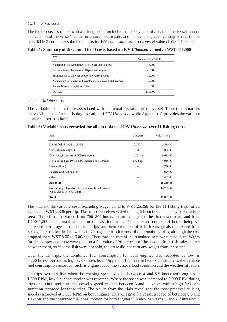
31
4.2.1 Fixed costs
The fixed costs associated with a fishing operation include the repayment of a loan on the vessel, annualdepreciation of the vessel’s value, insurance, boat repairs and maintenance, and licensing or registrationfees. Table 5 summarises the fixed costs for F/V Ulimasao, based on a vessel value of WST 400,000.
Table 5: Summary of the annual fixed costs based on F/V Ulimasao valued at WST 400,000
Item
Annual loan repayment based on 12 per cent interest 48,000
Depreciation of the vessel at 10 per cent per year 40,000
Insurance based on 9 per cent of the vessel’s value 36,000
Annual cost for repairs and maintenance estimated at 3 per cent 12,000
Annual licence or registration fees 700
TOTAL 136,700
Annual value (WST)
4.2.2 Variable costs
The variable costs are those associated with the actual operation of the vessel. Table 6 summarisesthe variable costs for the fishing operation of F/V Ulimasao, while Appendix G provides the variablecosts on a per-trip basis.
Table 6: Variable costs recorded for all operations of F/V Ulimasao over 11 fishing trips
Item Amount Value (WST)
Diesel fuel @ WST 1.1959/l 5,292 l 6,329.46
Oils (lube and engine) 160 l 865.38
Bait in kg (in cartons of different sizes) 1,205 kg 9,621.62
Ice in 25 kg bags (WST 8.00 reducing to 6.00/bag) 672 bags 4,916.00
Victuals (food) – 2,240.00
Replacement fishing gear – 950.00
Other – 1,437.00
Sub-total – 26,359.46
Crews’ wages based on 20 per cent of the sold catch – 14,702.44 value shared between them
Total 41,061.90
The total for the variable costs excluding wages came to WST 26,359 for the 11 fishing trips, or anaverage of WST 2,396 per trip. The trips themselves varied in length from three to six days (one to foursets). The effort also varied from 700–800 hooks set on average for the first seven trips, and from1,100–1,200 hooks used per set for the last four trips. The increased number of hooks being setincreased bait usage on the last four trips, and hence the cost of bait. Ice usage also increased from60 bags per trip for the first 4 trips to 70 bags per trip for most of the remaining trips, although the costdropped from WST 8.00 to 6.00/bag. Therefore the cost of ice remained somewhat consistent. Wagesfor the skipper and crew were paid on a flat value of 20 per cent of the income from fish sales sharedbetween them, so if some fish were not sold, the crew did not earn any wages from these fish.
Over the 11 trips, the combined fuel consumption for both engines was recorded as low as5.206 litres/hour and as high as 8.0 litres/hour (Appendix H). Several factors contribute to the variablefuel consumption recorded, such as engine speed, the vessel’s load condition and the weather situation.
On trips two and five when the cruising speed was set between 4 and 5.5 knots with engines at1,500 RPM, low fuel consumption was recorded. Where the speed was increased to 3,000 RPM duringtrips one, eight and nine, the vessel’s speed reached between 8 and 11 knots, with a high fuel con-sumption recorded for those trips. The results from the trials reveal that the most practical cruisingspeed is achieved at 2,500 RPM on both engines. This will give the vessel a speed of between 6.5 and10 knots and the combined fuel consumption for both engines will vary between 6.5 and 7.2 litres/hour.
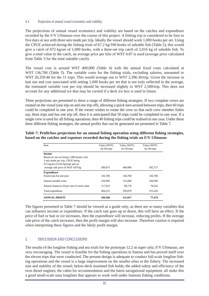
32
4.3 Projection of annual vessel economics and viability
The projections of annual vessel economics and viability are based on the catches and expenditurerecorded by the F/V Ulimasao over the course of this project. A fishing trip is considered to be four tofive days at sea with three sets made per trip. Ideally the vessel should work 1,000 hooks per set. Usingthe CPUE achieved during the fishing trials of 67.2 kg/100 hooks of saleable fish (Table 2), this wouldgive a catch of 672 kg/set of 1,000 hooks, with a three-set trip catch of 2,016 kg of saleable fish. Togive a total value to the catch, an average price per kilo of WST 4.87 is used (average price calculatedfrom Table 3 for the total saleable catch).
The vessel cost is around WST 400,000 (Table 4) with the annual fixed costs calculated atWST 136,700 (Table 5). The variable costs for the fishing trials, excluding salaries, amounted toWST 26,359.46 for the 11 trips. This would average out to WST 2,396.30/trip. Given the increase inbait use and cost associated with setting 1,000 hooks per set that is not truly reflected in the average,the estimated variable cost per trip should be increased slightly to WST 2,500/trip. This does notaccount for any additional ice that may be carried if a deck ice box is used in future.
Three projections are presented to show a range of different fishing strategies. If two complete crews arerotated on the vessel (one trip on and one trip off), allowing a quick turn-around between trips, then 60 tripscould be completed in one year. If the owner wishes to rotate the crew so that each crew member fishessay, three trips and has one trip off, then it is anticipated that 50 trips could be completed in one year. If asingle crew is used for all fishing operations, then 40 fishing trips could be realised in one year. Under thesethree different fishing strategies, the annual profits that can be generated are presented in Table 7.
Table 7: Profit/loss projections for an annual fishing operation using different fishing strategies,based on the catches and expenses recorded during the fishing trials on F/V Ulimasao
Item
IncomeBased on one set being 1,000 hooks with3 sets made per trip, CPUE being672 kg/set (2,016 kg/trip) and an average sale price of WST 4.87/kg 589,075 490,896 392,717
ExpenditureFixed costs for one year 136,700 136,700 136,700
Annual variable costs 150,000 125,000 100,000
Salaries based on 20 per cent of catch value 117,815 98,179 78,543
Total expenditure 404,515 359,879 315,243
ANNUAL PROFIT 184,560 131,017 77,474
Value (WST) for 40 trips
Value (WST) for 60 trips
Value (WST)for 50 trips
The figures presented in Table 7 should be viewed as a guide only, as there are so many variables thatcan influence income or expenditure. If the catch rate goes up or down, this will have an effect. If theprice of fuel or bait or ice increases, then the expenditure will increase, reducing profits. If the averagesale price of the catch increases, then the profit margin will also increase. Therefore caution is requiredwhen interpreting these figures and the likely profit margin.
5. DISCUSSION AND CONCLUSIONS
The results of the longline fishing and sea trials for the prototype 12.2 m super alia, F/V Ulimasao, arevery encouraging. The vessel is feasible for the fishing operations in Samoa and has proved itself overthe eleven trips that were conducted. The present design is adequate to conduct full-scale longline fish-ing operations and the vessel is a large improvement on the smaller alias in the fishery. The increasedsize and stability of the vessel; below-deck insulated fish holds; the added safety and efficiency of thetwin diesel engines; the cabin for accommodation and the latest navigational equipment, all make thisa good small-scale tuna longliner that appears to work well under Samoan fishing conditions.
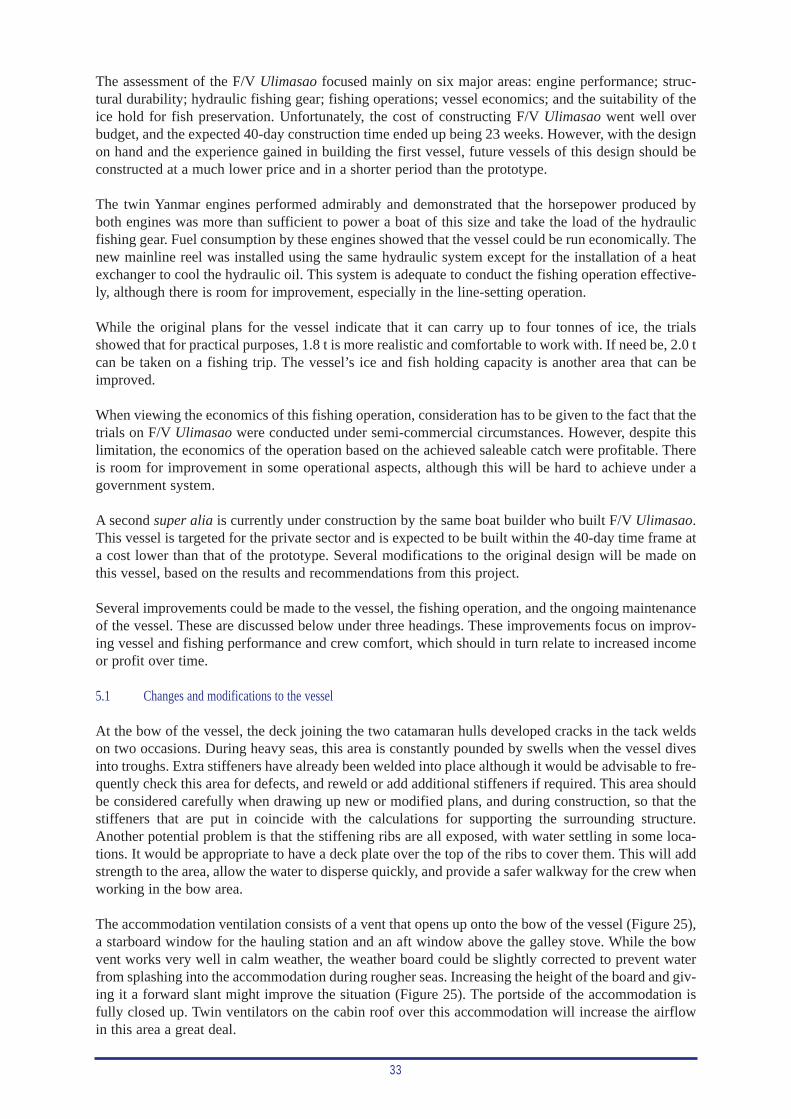
33
The assessment of the F/V Ulimasao focused mainly on six major areas: engine performance; struc-tural durability; hydraulic fishing gear; fishing operations; vessel economics; and the suitability of theice hold for fish preservation. Unfortunately, the cost of constructing F/V Ulimasao went well overbudget, and the expected 40-day construction time ended up being 23 weeks. However, with the designon hand and the experience gained in building the first vessel, future vessels of this design should beconstructed at a much lower price and in a shorter period than the prototype.
The twin Yanmar engines performed admirably and demonstrated that the horsepower produced byboth engines was more than sufficient to power a boat of this size and take the load of the hydraulicfishing gear. Fuel consumption by these engines showed that the vessel could be run economically. Thenew mainline reel was installed using the same hydraulic system except for the installation of a heatexchanger to cool the hydraulic oil. This system is adequate to conduct the fishing operation effective-ly, although there is room for improvement, especially in the line-setting operation.
While the original plans for the vessel indicate that it can carry up to four tonnes of ice, the trialsshowed that for practical purposes, 1.8 t is more realistic and comfortable to work with. If need be, 2.0 tcan be taken on a fishing trip. The vessel’s ice and fish holding capacity is another area that can beimproved.
When viewing the economics of this fishing operation, consideration has to be given to the fact that thetrials on F/V Ulimasao were conducted under semi-commercial circumstances. However, despite thislimitation, the economics of the operation based on the achieved saleable catch were profitable. Thereis room for improvement in some operational aspects, although this will be hard to achieve under agovernment system.
A second super alia is currently under construction by the same boat builder who built F/V Ulimasao.This vessel is targeted for the private sector and is expected to be built within the 40-day time frame ata cost lower than that of the prototype. Several modifications to the original design will be made onthis vessel, based on the results and recommendations from this project.
Several improvements could be made to the vessel, the fishing operation, and the ongoing maintenanceof the vessel. These are discussed below under three headings. These improvements focus on improv-ing vessel and fishing performance and crew comfort, which should in turn relate to increased incomeor profit over time.
5.1 Changes and modifications to the vessel
At the bow of the vessel, the deck joining the two catamaran hulls developed cracks in the tack weldson two occasions. During heavy seas, this area is constantly pounded by swells when the vessel divesinto troughs. Extra stiffeners have already been welded into place although it would be advisable to fre-quently check this area for defects, and reweld or add additional stiffeners if required. This area shouldbe considered carefully when drawing up new or modified plans, and during construction, so that thestiffeners that are put in coincide with the calculations for supporting the surrounding structure.Another potential problem is that the stiffening ribs are all exposed, with water settling in some loca-tions. It would be appropriate to have a deck plate over the top of the ribs to cover them. This will addstrength to the area, allow the water to disperse quickly, and provide a safer walkway for the crew whenworking in the bow area.
The accommodation ventilation consists of a vent that opens up onto the bow of the vessel (Figure 25),a starboard window for the hauling station and an aft window above the galley stove. While the bowvent works very well in calm weather, the weather board could be slightly corrected to prevent waterfrom splashing into the accommodation during rougher seas. Increasing the height of the board and giv-ing it a forward slant might improve the situation (Figure 25). The portside of the accommodation isfully closed up. Twin ventilators on the cabin roof over this accommodation will increase the airflowin this area a great deal.
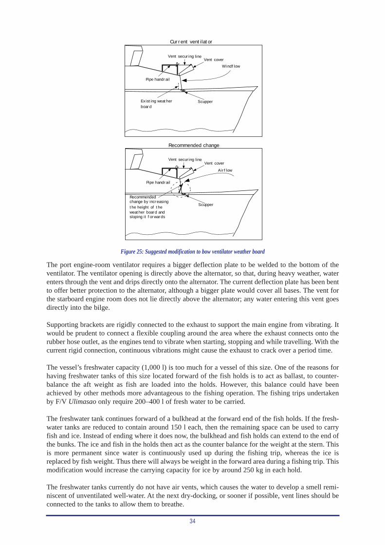
34
Windflow
Vent securing lineVent cover
Scupper
Current ventilator
Recommendedchange by increasingthe height of theweather board andsloping it forwards
Vent cover
Airflow
Scupper
Vent securing line
Recommended change
Pipe handrail
Pipe handrail
Existing weatherboard
Figure 25: Suggested modification to bow ventilator weather board
The port engine-room ventilator requires a bigger deflection plate to be welded to the bottom of theventilator. The ventilator opening is directly above the alternator, so that, during heavy weather, waterenters through the vent and drips directly onto the alternator. The current deflection plate has been bentto offer better protection to the alternator, although a bigger plate would cover all bases. The vent forthe starboard engine room does not lie directly above the alternator; any water entering this vent goesdirectly into the bilge.
Supporting brackets are rigidly connected to the exhaust to support the main engine from vibrating. Itwould be prudent to connect a flexible coupling around the area where the exhaust connects onto therubber hose outlet, as the engines tend to vibrate when starting, stopping and while travelling. With thecurrent rigid connection, continuous vibrations might cause the exhaust to crack over a period time.
The vessel’s freshwater capacity (1,000 l) is too much for a vessel of this size. One of the reasons forhaving freshwater tanks of this size located forward of the fish holds is to act as ballast, to counter-balance the aft weight as fish are loaded into the holds. However, this balance could have beenachieved by other methods more advantageous to the fishing operation. The fishing trips undertakenby F/V Ulimasao only require 200–400 l of fresh water to be carried.
The freshwater tank continues forward of a bulkhead at the forward end of the fish holds. If the fresh-water tanks are reduced to contain around 150 l each, then the remaining space can be used to carryfish and ice. Instead of ending where it does now, the bulkhead and fish holds can extend to the end ofthe bunks. The ice and fish in the holds then act as the counter balance for the weight at the stern. Thisis more permanent since water is continuously used up during the fishing trip, whereas the ice isreplaced by fish weight. Thus there will always be weight in the forward area during a fishing trip. Thismodification would increase the carrying capacity for ice by around 250 kg in each hold.
The freshwater tanks currently do not have air vents, which causes the water to develop a smell remi-niscent of unventilated well-water. At the next dry-docking, or sooner if possible, vent lines should beconnected to the tanks to allow them to breathe.
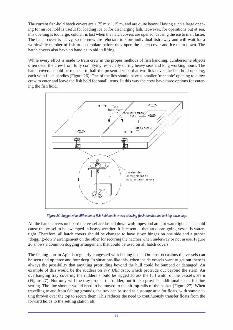
35
The current fish-hold hatch covers are 1.75 m x 1.15 m, and are quite heavy. Having such a large open-ing for an ice hold is useful for loading ice or for discharging fish. However, for operations out at sea,this opening is too large; cold air is lost when the hatch covers are opened, causing the ice to melt faster.The hatch cover is heavy, so the crew are reluctant to store individual fish away and will wait for aworthwhile number of fish to accumulate before they open the hatch cover and ice them down. Thehatch covers also have no handles to aid in lifting.
While every effort is made to train crew in the proper methods of fish handling, cumbersome objectsoften deter the crew from fully complying, especially during heavy seas and long working hours. Thehatch covers should be reduced to half the present size so that two lids cover the fish-hold opening,each with flush handles (Figure 26). One of the lids should have a smaller ‘manhole’ opening to allowcrew to enter and leave the fish hold for small items. In this way the crew have three options for enter-ing the fish hold.
All the hatch covers on board the vessel are lashed down with ropes and are not watertight. This couldcause the vessel to be swamped in heavy weather. It is essential that an ocean-going vessel is water-tight. Therefore, all hatch covers should be changed to have sit-on hinges on one side and a proper‘dogging-down’ arrangement on the other for securing the hatches when underway or not in use. Figure26 shows a common dogging arrangement that could be used on all hatch covers.
The fishing port in Apia is regularly congested with fishing boats. On most occasions the vessels canbe seen tied up three and four deep. In situations like this, when inside vessels want to get out there isalways the possibility that anything protruding beyond the hull could be bumped or damaged. Anexample of this would be the rudders on F/V Ulimasao, which protrude out beyond the stern. Anoverhanging tray covering the rudders should be rigged across the full width of the vessel’s stern(Figure 27). Not only will the tray protect the rudder, but it also provides additional space for linesetting. The line shooter would need to be moved to the aft top rails of the basket (Figure 27). Whentravelling to and from fishing grounds, the tray can be used as a storage area for floats, with some net-ting thrown over the top to secure them. This reduces the need to continuously transfer floats from theforward holds to the setting station aft.
Figure 26: Suggested modification to fish-hold hatch covers, showing flush handles and locking-down dogs
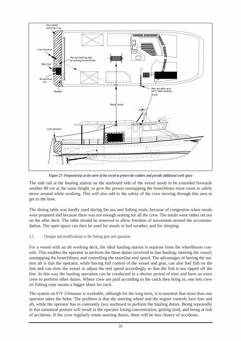
36
Line shooter
Bait box
Relay block
Retractable armwith main haulingblock
Branchlinebin
Person baiting andattaching branchlines
Rudder
Line shooter
.
Extendedworking tray
The side rail at the hauling station on the starboard side of the vessel needs to be extended forwardsanother 80 cm at the same height, to give the person unsnapping the branchlines more room to safelymove around while working. This will also add to the safety of the crew moving through this area toget to the bow.
The dining table was hardly used during the sea and fishing trials, because of congestion when mealswere prepared and because there was not enough seating for all the crew. The meals were rather set outon the after deck. The table should be removed to allow freedom of movement around the accommo-dation. The open space can then be used for meals in bad weather, and for sleeping.
5.2 Changes and modifications to the fishing gear and operation
For a vessel with an aft working deck, the ideal hauling station is separate from the wheelhouse con-sole. This enables the operator to perform the three duties involved in line hauling: steering the vessel;unsnapping the branchlines; and controlling the mainline-reel speed. The advantages of having the sta-tion aft is that the operator, while having full control of the vessel and gear, can also feel fish on theline and can slow the vessel or adjust the reel speed accordingly so that the fish is not ripped off theline. In this way the hauling operation can be conducted in a shorter period of time and have an extracrew to perform other duties. Where crew are paid according to the catch they bring in, one less crewon fishing trips means a bigger share for each.
The system on F/V Ulimasao is workable, although for the long term, it is essential that more than oneoperator takes the helm. The problem is that the steering wheel and the engine controls face fore andaft, while the operator has to constantly face starboard to perform the hauling duties. Being repeatedlyin this unnatural posture will result in the operator losing concentration, getting tired, and being at riskof accidents. If the crew regularly rotate steering duties, there will be less chance of accidents.
Figure 27: Proposed tray at the stern of the vessel to protect the rudders and provide additional work space
37
The operator’s starboard window should be changed to a watertight sliding window to prevent rain andseawater from entering the wheelhouse. This will allow the operator to limit the opening when it is rain-ing or when there are rough seas.
The main engine controls are cable operated and are situated within arm’s reach of the operator, on theconsole to the right of the steering wheel. Each engine has a separate control for engaging the clutchand for operating the engine revolutions. Each engine also has a trolling valve that can be operated toa recommended 1,200 revolutions. While the clutch and engine throttle controls are necessary formanoeuvring the vessel, the trolling valves are unnecessary for longline operations, especially withtwin engine vessels, and should not be placed on future vessels.
The pump for the hydraulic system is currently being driven directly off the main port engine. Thepump is permanently connected to the main engine by a durable hardened plastic coupling. With thissystem, the hydraulic pump is continuously operated as soon as the port engine is started. If a problemdevelops along the hydraulic lines, the port engine will have to be shut down for repair. The hydrauliclines, leading from the tank to the pump then back through the return line and flow control valve, areconstantly under pressure as soon as the port engine is running.
Hydraulic oil flow can be diverted to the reservoir without having to go through the whole system, butit still has to travel through the pump and back through the return line. This diversion is done by shut-ting down the flow control valve, so that the lines leading to the mainline reel and line shooter will haveno oil flow and will not be subject to oil pressure during the voyage. The best solution though is toinstall a clutch system (electric or manual) between the main engine and the pump. In this way, thepump can be disengaged when not required and engaged when fishing operations begin. This will savethe pump from unnecessary wear and tear and the oil viscosity from thinning out too soon.
Every vessel operator has a different way or style for hauling back the mainline. The main prioritythough, must be to ensure that the mainline does not get caught on the propellers and break, as this willresult in gear being permanently lost or delays in the fishing time. While hauling, it is wise to keep anarrow angle between the vessel and the mainline and ensure that the vessel absorbs as much of thestress as possible. This will safeguard the line from breaking.
With twin-engine vessels, it is best to use the engine opposite the line-retrieving area to manoeuvre thevessel. This ensures that the engine on the hauling side is idle and less likely to catch the trailingbranchlines. Only in rough seas and strong winds should both engines be used for hauling. Normally,only one engine is necessary to carry out fishing movements while the other engine can be used to bal-ance off the movements when necessary. It would also be sensible to have the regularly dormant enginedrive the hydraulics during hauling while the other engine drives the vessel.
For future designs, thought should be given to setting-up the system so that the hydraulics run off theengine on the hauling side, while the engine opposite the hauling side can be used to propel the vessel.This will at least divide the work load between the two engines.
Two different-sized mainline reels were used on the vessel during the fishing trials. The first held up to20 nm of 3.5 mm monofilament, while the second held up to 30 nm of 3.5 mm monofilament mainline.The first reel was mounted athwart-ships, while the second, larger reel had to be mounted fore-and-aft,which used much more deck space. The ideal mainline reel for this size of vessel would be one thatholds up to 25 nm of 3.5 mm mainline. A reel of this capacity should be of a suitable size to be mountedathwart-ships close to the back of the cabin. This will minimise the deck space used for installation, thusproviding more workspace or storage areas.
The limited ice-carrying capacity of this vessel, and a possible means of increasing the capacity bothfor ice and fish, was discussed in the previous section. Even with larger fish holds, the capacity for car-rying ice remains limited compared to that for fish, if the catch is to be iced correctly. To overcome this,an additional 1,000 kg of ice could be carried in an ice box on deck. A marine architect will need to beconsulted to determine whether the extra weight will suit the vessel’s load ability, or work against it.
38
If deemed safe, a suitable ice box should be constructed. However, the deck ice box must only be usedfor carrying ice, with all fish being iced in the fish hold. No fish should be iced in the deck ice box, asthis may alter the stability of the vessel as it fills with fish during a fishing trip.
It was noticed during the last trip of the trials that the forward searchlight and the forward bow lightboth feed off one line and the same secondary switch. This set up is not practical for searching purposesas the glare of the forward deck light inhibits the searcher from peering out into the wake of the search-light. When searches are carried out at night, the vessel needs to be in complete darkness with only thesearchlight beam searching the waters and the searchlight forward of the user. Separate switches andpower lines should be rigged up for the two lights so that they work independently of each other. Mainswitch number six was not in use, so the forward deck light can be connected directly to this.
Storage space for fishing gear on the vessel is very limited. A plywood storage box has been tem-porarily rigged in the space between the sleeping berths and directly below the forward vent duct.Fishing gears and spare parts are located in this area for easy access during operations. These includestrobe lights, hooks, crimps, crimping machine, tool box, blocks, spikes, gloves, and batteries.A permanent aluminium box should be welded in this area with the edges rounded off to preventinjury to the crew. Permanent storage areas can also be built beneath the galley settee and the Captain’sbunk.
The Fisheries Division should look at purchasing an autopilot for the vessel in the near future. It willnot be difficult to integrate an autopilot into the current steering system. An autopilot will travel theshorter route between any two given points and will greatly minimise the workload of the crew. Onepoint preventing a good catch is the crew’s reluctance to steer the vessel to shift fishing grounds aftera hard night’s hauling in poor fishing grounds. In most cases, the crew can maintain a good watch butare too tired to concentrate on steering the whole way to a new fishing ground. A watch alarm can beset on the autopilot or the GPS, which requires the crew on watch to reset the alarm at designated times.
During line setting, the autopilot relieves one crew to perform other duties. With an autopilot, the line-setting operation can be pre-planned and the coordinates for altering course fed into the memory. Usingthe navigation mode, the vessel will automatically steer the coordinates chosen and alter course whenrequired. Fuel consumption will be lower than when manual steering is performed, and the coursesteered will be straighter.
The landed catch can be recorded in an organised manner if done by the vessel’s crew. One personshould be held fully responsible for the discharge of fish ashore, the vessel’s skipper. At present, manypeople are involved, which makes it difficult to monitor.
At the off-loading point, four items are necessary: a work table, a weighing scale, a heavy cutting knifeand a bow saw. Fish should be discharged from the vessel and recorded one at a time. If systematicallycontrolled, the fish can be discharged very fast and efficiently recorded. No shore personnel should beallowed to touch the fish unless they are appointed by the vessel’s crew to assist in carrying the fishacross to the weighing table.
Since the fish go directly to a transport vehicle to be processed at a factory, vehicles should be used thathave overhead protection from the sun, or better still, full chilling facilities. The Fisheries Division’ssales and purchasing officer can take over once the fish have been weighed and stacked in the trans-port vehicle.
5.3 Vessel maintenance
The operating and periodic maintenance tables provided by the manufacturing company for the Yanmarengines should be strictly adhered to, to ensure maximum lifespan and smooth running. This is espe-cially true for all oil changes (engine and gearbox) and filter changes (oil and fuel). F/V Ulimasao doesnot have a qualified marine engineer to maintain the engines; this duty is delegated to the skipper ofthe vessel. It would be advisable to have a qualified marine engineer to periodically survey the enginesfor signs of deterioration and to recommend repairs or necessary upkeep.
39
Several sets of procedures were developed in the initial stages of the project to assist the skipper of thevessel. These were procedures for starting the main engine prior to departure (Appendix B), and theprocedures to be followed prior to and during line setting and hauling (Appendix C). Both sets ofprocedures were displayed on the cabin wall for easy reference. It is essential that these procedurescontinue to be followed.
Regular checks should be kept on the engine room when the vessel is underway. The hoses and the hoseclip connections especially need checking. The main suction lines from the seacocks to the engines andfrom the engines to the outlets are all connected by hose clips. These have already been doubled up asa safety measure but regular checks must still be done, as the grips on the clips may unwind due tovibration or corrosion.
The suction and outlet line for the deck water and heat exchanger pump is also connected by hose clips.Only when the vessel is carrying out fishing operations should this pump be run continuously. If a hosebecomes loose, the engine room will be flooded in a short time.
Another important item to check in the engine room is the stuffing box on each propeller shaft. If thepacking becomes worn, then water will enter the engine room. A simple adjustment can stop the flow,although if the packing is badly worn, it may need replacing.
Because the hydraulic system is permanently connected to the port engine, the hydraulic hoses and con-nections should also be regularly checked. Should a problem arise with the hydraulics that cannot berepaired at sea, the port engine should be shut down and the plastic coupling removed. This will allowthe port engine to continue running.
The port and starboard fuel tanks should be topped up regularly to prevent moisture from forminginside. They should be topped up after every second trip. The water traps on the fuel lines should bechecked regularly and the tanks drained immediately, if water exists.
The inlets for the saltwater wash line and the toilet flush line are both directly connected to the hosewithout any seacock valve at the base. This is not safe as there is no way to stop the flow of water if aleak develops in the middle portion of either inlet line. Therefore it is essential that at the next dry dock-ing, a seacock valve be connected to this and any other through-hull water inlets below water level. Thevalve can immediately be shut off while repairs are carried out on any leaks that develop.
Regular checks should be made to the vessel’s hull to spot any pitting due to electrolysis. Checks forelectrolysis should be done mainly around the echosounder transducer and the propeller. The zinc anodesshould be renewed as soon as around 75 per cent has corroded. At the end of the trials, the vessel wasstill free of electrolysis pitting and the zinc anodes were all intact with no sign of having deteriorated.
Regular checks should also be carried out for branchlines around the propeller shaft, as previous expe-riences have shown that the branchlines can build up and push through the shaft seal and cause leaksand damage to the propeller stern gland, especially when the snaps and hook are drawn into these areas.If any branchline materials are found to be wrapped around the shaft and propeller, they should beremoved immediately.
From time to time some equipment will fail while the vessel is at sea. In some cases, repairs can becarried out at sea, while at other times the repairs need to wait until the vessel returns to port. It isimportant for the skipper to report any breakdowns to the Fisheries Division either before or when thevessel reaches port. If this is done, the person in charge can arrange for the repairs to be made as soonas the vessel arrives in port, and definitely before the vessel heads to sea again.
An important part of any fishing operation is to maintain a clean, tidy and hygienic vessel. The fishholds should be scrubbed out with disinfectant after each trip, well rinsed and aired to ensure no deter-gent remains. The decks, especially where fish are landed and processed, should also be scrubbed downwith detergent after each trip. This includes any mats or pads used under the fish during processing.
40
6. RECOMMENDATIONS
Based on the work carried out and the range of objectives for this project, many recommendations aremade. For ease of presentation, the recommendations are presented here using the same headings as inSection 5 (Discussion and Conclusions), and are based on the observations and experience of theFisheries Development Officer. Many of the recommendations are made to improve the stature ofF/V Ulimasao, and be a guide for improvements on future designs for vessels of this type.
6.1 Changes and modifications to the vessel
It is recommended that:
(a) The bow area on F/V Ulimasao be regularly checked for possible cracks or defects in the weldsand strengthened as and if required;
(b) When drawing up new or modified plans for the super alia, consideration be given to adding stiff-eners, placed to coincide with the calculations for supporting the surrounding structure;
(c) A deck plate be welded over the top of the bow ribs and stiffeners to cover them and add strengthto the area;
(d) The height of the weather board in the bow ventilator be increased and the board sloped forward;
(e) Twin ventilators be mounted on the cabin roof over the portside accommodation to increase airflow;
(f) A larger deflection plate be welded to the bottom of the port engine room ventilator, to stop waterdripping onto the alternator;
(g) A flexible coupling be mounted between each engine and its exhaust system, at the rubber hoseoutlet, to minimise the chance of the exhaust pipes cracking;
(h) In future vessels, the freshwater tanks be made smaller to hold around 150 l each, and be locatedas far forward as possible;
(i) Future vessels of this design be constructed with the fish hold extended forwards to the end of thebunks, and the bulkhead be altered accordingly, to increase the fish-hold capacity;
(j) At the next dry docking of the vessel, or sooner if possible, vent lines be attached to the freshwatertanks to allow them to breathe;
(k) The hatch covers on the two ice holds be cut in half to make them more manageable, with one halfhaving a smaller ‘manhole’ opening as well;
(l) All hatch covers have flush handles mounted in them for ease of use;
(m) All hatch covers be fitted with a sit-on hinge on one side and a locking-down dog arrangement onthe other for securing the hatches and making them watertight;
(n) An overhanging tray be rigged across the full width of F/V Ulimasao’s stern to protect theexposed rudders that protrude out the stern;
(o) The side rail at the hauling station on the starboard side be extended forward by 80 cm at the sameheight; and
(p) The dining table be removed, leaving this space open.
41
6.2 Changes and modifications to the fishing gear and operation
It is recommended that:
(a) The skipper on F/V Ulimasao set up a rotation system with the crew so that they each take turnsat all aspects of the hauling operation;
(b) The operator’s window on the starboard side be replaced with a watertight sliding window;
(c) When future vessels of this design are built, there be no trolling valve fitted to the engines as thisis unnecessary for tuna longlining;
(d) A clutch system (electric or manual) be installed between the main engine and the hydraulic pump,to disengage the pump when not in operation;
(e) For future vessels of this design, the hydraulics be run off the engine adjacent to the hauling side,while the engine opposite the hauling side can be used to propel the vessel during line hauling;
(f) Future vessels of this design be fitted with a mainline reel that holds up to 25 nm of 3.5 mm main-line, with the reel mounted athwart-ships close to the back of the cabin to minimise the deck spaceused for installation;
(g) A marine architect be consulted to determine whether another ice box to hold around 1,000 kg ofice can be constructed on the aft deck without affecting the vessel’s load ability or stability;
(h) If deemed safe, a suitable ice box be constructed;
(i) The deck ice box only be used for carrying ice, with all fish being iced in the fish hold below deck;
(j) The forward searchlight and the forward bow light be placed on separate switches, (the forwarddeck light could be placed on main switch number six, which was not in use);
(k) A permanent aluminium box with rounded edges be constructed and welded in the space betweenthe sleeping berths, directly below the forward vent;
(l) The areas beneath the galley settee and the Captain’s bunk be converted to permanent storageareas;
(m) The Fisheries Division purchase an autopilot for F/V Ulimasao, and integrate it into the currentsteering system;
(n) Whenever the autopilot is used, the skipper ensure the watch alarm is set with a roster of times forresetting the alarm to ensure safety of the vessel;
(o) The skipper of F/V Ulimasao be responsible for the discharging and weighing of all catch from thevessel;
(p) A set process be put in place for discharging fish from F/V Ulimasao one at a time, with the fishprocessed if necessary (head removed on billfish), weighed, and the information recorded;
(q) All fish be transported to the processors or fish buyers in covered vehicles with shade for the fish,or preferably, full chilling facilities; and
(r) The sales and purchasing officer at fisheries be responsible for the fish once it has been weighedand placed in vehicles for marketing.
42
6.3 Vessel maintenance
It is recommended that:
(a) The maintenance tables provided by the manufacturer of the engines in F/V Ulimasao be closelyfollowed, especially the changing of engine and gearbox oils and all filters;
(b) The Fisheries Division has a qualified marine engineer do periodic surveys or checks on theengines of F/V Ulimasao for signs of deterioration, and recommend repairs or necessary upkeep;
(c) The procedures developed for starting the engine prior to departure, and for use during line settingand hauling be continued;
(d) The skipper of F/V Ulimasao make regular checks on all hoses and hose-clip connections, espe-cially those on the main seacocks to the engines, and from the engines to the outlets, and on thedeck water and heat exchanger pump;
(e) The stuffing box on each propeller shaft in the engine rooms be checked regularly, making adjust-ments and replacing packing when needed;
(f) The skipper of F/V Ulimasao regularly check the hydraulic hoses and connections. If a problem isfound that cannot be fixed at sea, the port engine should be shut down and the plastic couplingremoved, so the engine can be run without driving the hydraulic pump;
(g) Both fuel tanks be topped up at least after every second trip to minimise the chance of moistureforming in them;
(h) The water traps on the fuel lines be checked regularly, and the tanks drained immediately if mois-ture is detected inside;
(i) At the next dry docking of F/V Ulimasao, a seacock valve be connected to inlets for the saltwaterwash line and the toilet flush line, and any other through-hull water inlets below water level thatdo not already have a seacock valve;
(j) Regular checks be made on the vessel’s hull for electrolysis pitting, and that all zinc anodes bereplaced as soon as they are around 75 per cent corroded;
(k) Regular checks be made of the propeller shaft, with any branchline materials tangled or wrappedaround the shaft removed immediately;
(l) The skipper of the vessel report any repairs needed to the Fisheries Division before or when thevessel enters port, so that repairs can be made before the vessel heads to sea again; and
(m) A system be set in place to ensure that when the fish has been discharged from the vessel, the fishholds are scrubbed out with disinfectant, rinsed and aired, and the deck washed down with deter-gent, especially in areas where fish are landed and processed.
43
7. REFERENCES
ANON. 1998. Annual Report, 1996/97. Fisheries Division, Ministry of Agriculture, Forests, Fisheries,and Meteorology, Samoa. 34 p.
ANON. 1999. Minilog manual on temperature/depth recorders (TDRs). 4 p.
ANON. Unpublished. Samoan Fisheries Division completion report on the new alia design project.Samoan Fisheries Division, Apia, Samoa. 5 p.
BEVERLY, S. 2000. Fisheries Development Section explores new technologies on a Tongan longlineboat, F/V Kylie. Fisheries Newsletter No. 92, Secretariat of the Pacific Community, Noumea,New Caledonia. 20–27.
BLANC, M. 1996. On-board handling of sashimi-grade tuna—a practical guide for crew members.South Pacific Commission, Noumea, New Caledonia. 27 p.
CHAPMAN, L. 1998. The rapidly expanding and changing tuna longline fishery in Samoa. SPCFisheries Newsletter No. 84, Secretariat of the Pacific Community, Noumea, New Caledonia.18–31.
FA’ASILI, U. 1997. Review, redesigning and construction demonstration of alia fishing boats inSamoa. A project proposal submitted for funding assistance from UNDP/FFA. 5 p.
FA’ASILI, U. & S. TIME. 1997. Alia Longline Fishery in Samoa. Paper presented to the Conferenceon Building Sustainable Tuna Industry in Pacific Islands, Maui Centre, United States (3–8November, 1997). 4 p.
KING, M. & U. FA’ASILI. 1997. Fisheries in Western Samoa. Fisheries situation report, FisheriesDivision, Ministry of Agriculture, Forests, Fisheries & Meteorology. 3 p.
PASSFIELD, K. & A. MULIPOLA. 1999. Commercial fisheries profile: the commercial tuna fisheryin Samoa. Government of Samoa Fisheries Project, an AusAID-assisted project of the FisheriesDivision, Samoa. 23 p.
SOKIMI, W., P. WATT & L. CHAPMAN. 2000. Fisheries Development Section Report of technicalassistance to the Fisheries Division of Samoa and the tuna longline industry (12 March to 10May, and 4 October to 20 December 1999). Secretariat of the Pacific Community, Noumea, NewCaledonia. 51 p.
SPC. 2000. Oceania Population 2000. Compiled by the Demography/Population Programme,Secretariat of the Pacific Community, Noumea, New Caledonia. 8 p.
WATT, P., L. CHAPMAN & P. CUSACK. 1998. Report on small-scale tuna fisheries development inWestern Samoa (27 September 1990 – 27 July 1991). Capture Section, Unpublished Report No.22. South Pacific Commission, Noumea, New Caledonia. 60 p.
WATT, P. & S. MOALA. 1999. Estimates of rejection in the Samoan tuna fishery. Government ofSamoa Fisheries Project, an AusAID-assisted project of the Fisheries Division, Samoa. 18 p.

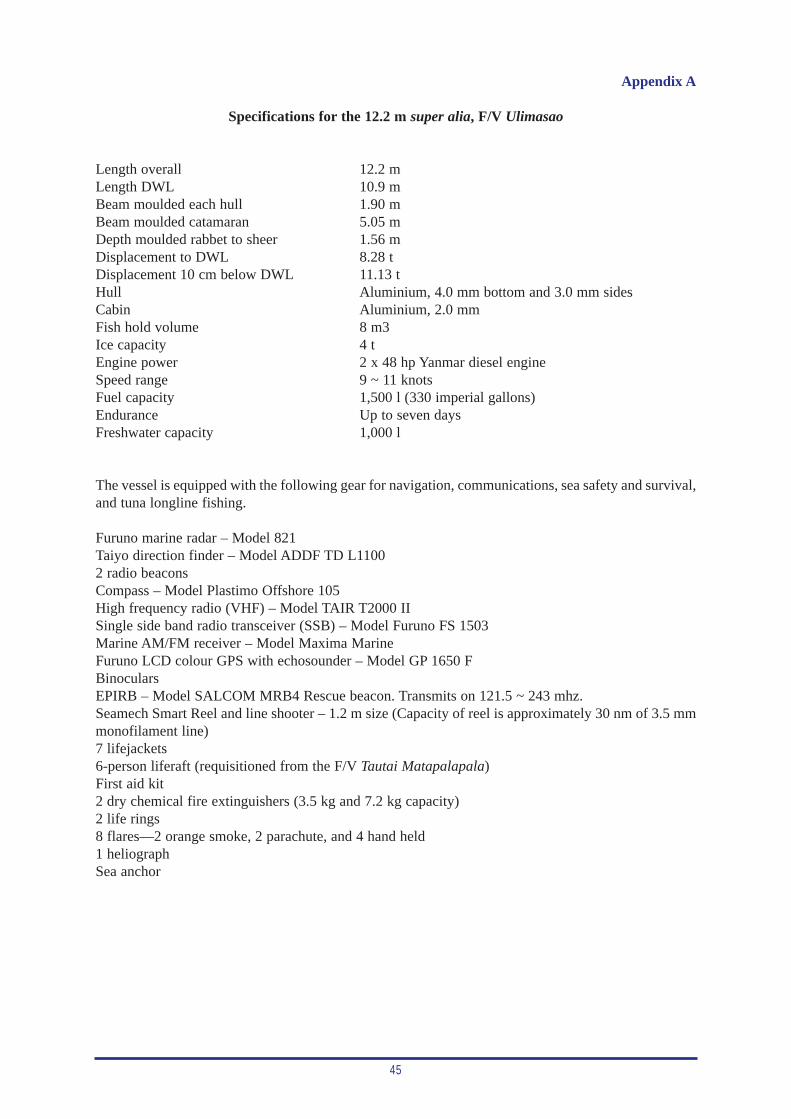
45
Appendix A
Specifications for the 12.2 m super alia, F/V Ulimasao
Length overall 12.2 mLength DWL 10.9 mBeam moulded each hull 1.90 mBeam moulded catamaran 5.05 mDepth moulded rabbet to sheer 1.56 mDisplacement to DWL 8.28 tDisplacement 10 cm below DWL 11.13 tHull Aluminium, 4.0 mm bottom and 3.0 mm sidesCabin Aluminium, 2.0 mmFish hold volume 8 m3Ice capacity 4 tEngine power 2 x 48 hp Yanmar diesel engineSpeed range 9 ~ 11 knotsFuel capacity 1,500 l (330 imperial gallons)Endurance Up to seven daysFreshwater capacity 1,000 l
The vessel is equipped with the following gear for navigation, communications, sea safety and survival,and tuna longline fishing.
Furuno marine radar – Model 821Taiyo direction finder – Model ADDF TD L11002 radio beaconsCompass – Model Plastimo Offshore 105High frequency radio (VHF) – Model TAIR T2000 IISingle side band radio transceiver (SSB) – Model Furuno FS 1503Marine AM/FM receiver – Model Maxima MarineFuruno LCD colour GPS with echosounder – Model GP 1650 FBinocularsEPIRB – Model SALCOM MRB4 Rescue beacon. Transmits on 121.5 ~ 243 mhz.Seamech Smart Reel and line shooter – 1.2 m size (Capacity of reel is approximately 30 nm of 3.5 mmmonofilament line)7 lifejackets6-person liferaft (requisitioned from the F/V Tautai Matapalapala)First aid kit2 dry chemical fire extinguishers (3.5 kg and 7.2 kg capacity)2 life rings8 flares—2 orange smoke, 2 parachute, and 4 hand held1 heliographSea anchor

47
Appendix B
Main engine starting procedures prior to departure
Every new operator on the vessel should consult the Operating Instructions and Periodic Maintenancetable attached to the bulkhead in the wheelhouse. For everyday procedures the following instructionswill greatly benefit the operator.
• Ensure that there is no water in the fuel tank. • Top up the cooling water reservoir on the engine.• Check engine oil level and top up if necessary.• Ensure that the engine oil and filters are within the recommended time of usage. If not, change all
filters and renew oil.• Check the gearbox oil level and top up to mark if necessary.• Check battery water level and top up if necessary. The full level mark is the extension below the
call port cap.
(It is important that all oil levels are topped up to the mark indicated on the dipstick. Overfillingwill cause the oil to build up pressure and leak,out).
• Take fuel level reading before starting each engine.• Note the engine hours before starting each engine.• Shut the hydraulic flow control valve on the port engine.• Disconnect drive belt for the deck water hose and the hydraulic cooling system (port engine).• Ensure that the main switches on the switchboard in the wheelhouse are turned off. • Turn on the main keys in the engine room and start engine.• Turn on the main switch on the switchboard and all power switches. (Note: if the port battery bank
is to be the power supplier for the first leg then only the port main switch and the port breakerswitch is to be turned on. Make sure that the starboard main switches are turned off. Vice versa ifthe starboard battery bank is used).
• Remove the camlock cap from the hydraulic tank filling port so that the tank's breather is opera-tional for the trip.

49
Appendix C
Procedures to be followed prior to and during line setting and line hauling
The following procedures for line setting and hauling were developed for F/V Ulimasao, to set a rou-tine in place, plus providing these procedures in writing for future people to operate the vessel.
Setting operation procedures
• Shut down port engine and connect drive belt for the deck water hose and hydraulic cooling system.
• Check cooling water and oil level on the port engine before restarting.
• Ensure that the two control valves on the line shooter are in the ‘off’ position.
• Turn on the hydraulic flow control valve (in the port engine room) to its maximum limit.
• Open up (anti-clockwise) the free-spooling valve on the mainline reel and run the mainline to theline shooter through the guide block.
• Connect up the floatlines, buoys and radio beacons.
• Switch on the radio beacon after a series of test signals.
• Disconnect the level-wind drive belt and wind the guide all the way to the corner.
• Shut the free-spooling valve on the mainline reel and open up (anti-clockwise) the smaller settingvalve.
• Push the speed control lever beside the two valves aft—towards the line shooter.
• Set the cable control lever in the wheelhouse to the line-setting position.
• Connect the extra return line from the hydraulic system to the tank through the tank filling port.
• Hook up the bait-setting box.
• Note: Bait has to be thawed out well in advance before setting. Thawing time depends on thefrozen condition of the bait. This should be done without running water over it.
• Deploy the first radio beacon and float, then set the vessel in motion at dead slow ahead(1,000 RPM). Mark the position of deployment (latitude and longitude).
• Turn on the main valve on the line shooter, then adjust the speed valve on the shooter to obtain thesetting speed required. Gradually increase the setting RPM so that no jerking stress is put on themainline reel and line shooter rubbers.
• Gradually increase the vessel’s engine RPMs to maximum setting speed (2,200 to 2,500 RPM).This has to co-ordinate with the increase in line-shooter RPMs.
• During line setting, should coordination problems arise between the line shooter and the mainlinereel, open up the free-spooling valve on the reel. Do not release the cable control lever in thewheelhouse.
50
• As the mainline is deployed and further coordination problems arise, release the cable control leverin the wheelhouse to the neutral position. This should be sufficient to carry the setting operation tothe end.
• At the end of the setting operation, the line-shooter speed and the mainline-reel rotation should bereduced simultaneously until both are stopped. This is done by having someone gradually reducethe speed control on the line shooter, while another person gradually eases down on the free-spooling valve on the mainline reel until it is shut and the reel stops. Caution should be taken atthis time to ensure that the mainline reel does not shut down before the line shooter. If thishappens, the line shooter will continue to pull the mainline from the reel, and this can resultin line breakage or can put a lot of pressure on the hydraulic lines, which may rupture at somepoint. On the other hand, having the line shooter shut down before the mainline reel stopsrotating will only result in excess line being piled up on the deck.
• Once the setting operation has ceased and the vessel has stopped, open up the free-spooling valveto unwind the remainder of the line on the reel and connect the end of the line to the end radio beaconand floats. Ensure that the signal from the beacon has been tested and that the switch is in the ‘On’position before deploying.
• Note down the position where the radio beacon has been deployed and mark this on the GPS. Thiswill serve as a back up to locating the beacon should a failure in the system arise.
Hauling operation procedures
• After retrieving the radio beacon, turn on the hydraulic-flow control valve and connect the mainline to the reel.
• Turn off the radio beacon.
• Connect back the drive belt for the level-wind guide.
• Ensure that the belt for the deck water pump is connected and functional.
• While the cable control lever is in the neutral position, shut down the free-spooling valve and thesmaller setting valve.
• Set the speed lever on the reel to the preferred hauling speed. If set towards the reel, a higher speedwill be achieved. If set away from the reel, a slower speed will be achieved.
• The cable control lever in the wheelhouse engages and disengages the reel.
• During hauling, as the mainline builds up on the reel, a further reduction in speed will be required.This can be achieved by reducing the hydraulic oil flow by adjusting the flow control valve.
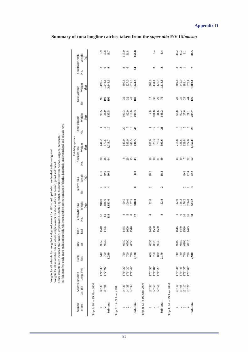
51
Wei
ghts
for
all
sale
able
fis
h ar
e gi
lled
and
gutte
d, e
xcep
t for
bill
fish
and
opa
h w
hich
are
hea
ded,
taile
d an
d gu
tted.
Wei
ghts
for a
ll un
sale
able
fish
are
who
le w
eigh
ts e
xcep
t for
sha
rks
whi
ch a
re h
eade
d, g
utte
d an
d fi
nned
.O
ther
sal
eabl
e ca
tch
incl
uded
blu
e m
arlin
, str
iped
mar
lin, s
hort
bill
spea
rfis
h, b
road
bill
swor
dfis
h, w
ahoo
, ski
pjac
k, b
arra
cuda
,oi
lfis
h, p
omfr
et, o
pah,
mah
i mah
i and
sun
fish
, whi
le u
nsal
eabl
e sp
ecie
s co
nsis
ted
of s
hark
s, la
ncet
fish
, sna
ke m
acke
rel a
nd p
elag
ic r
ays.
Cat
ch b
y sp
ecie
sN
umbe
rH
ook
Tim
eT
ime
of s
ets
Lat
. (S)
Lon
g. (
W)
Nos
.se
tha
ulN
o.W
eigh
tN
o.W
eigh
tN
o.W
eigh
tN
o.W
eigh
tN
o.W
eigh
tN
o.W
eigh
t(k
g)(k
g)(k
g)(k
g)(k
g)(k
g)
Tri
p 1:
16
to 1
9 M
ay 2
000
114
° 39
'17
1° 3
0'54
006
5515
4057
948.
01
11.0
2844
1.2
499
.590
1,49
9.7
35.
92
15°
08'
172°
02'
700
0730
1405
6188
5.6
349
.536
577.
56
36.0
106
1,54
8.6
613
.8Su
b-to
tal
1,24
011
81,
833.
64
60.5
641,
018.
710
135.
519
63,
048.
39
19.7
Tri
p 2:
5 t
o 9
June
200
0
114
° 36
'17
1° 3
2'72
006
4014
354
60.5
814
5.0
2019
0.3
3239
5.8
811
5.0
214
° 38
'17
1° 3
0'70
007
0016
005
100.
020
345.
07
82.0
3252
7.0
651
.83
14°
34'
171°
42'
710
0650
1510
815
7.5
1524
6.5
1821
8.0
4162
2.0
Sub-
tota
l2,
130
1731
8.0
00.
043
736.
545
490.
310
51,
544.
814
166.
8
Tri
p 3:
12
to 1
6 Ju
ne 2
000
112
° 52
'17
0° 5
3'60
006
3514
304
52.8
218
.210
187.
01
4.8
1726
2.8
212
° 58
'17
1° 0
4'75
006
2015
3018
329.
312
101.
830
431.
13
6.4
312
° 51
'17
1° 2
0'82
006
4015
3021
379.
38
41.6
2942
0.9
Sub-
tota
l2,
170
452
.82
18.2
4989
5.6
2114
8.2
761,
114.
83
6.4
Tri
p 4:
24
to 2
9 Ju
ne 2
000
113
° 11
'17
3° 3
4'74
007
0015
151
22.0
1421
5.8
864
.823
302.
63
44.2
213
° 08
'17
3° 4
6'74
006
5014
406
118.
219
331.
610
92.2
3554
2.0
343
.23
13°
12'
173°
37'
740
0900
1520
1017
6.2
249
.87
129.
85
27.6
2438
3.4
11.
14
13°
27'
173°
09'
720
0715
1445
1626
6.8
112
.422
374.
85
21.1
4467
5.1
Sub-
tota
l2,
940
3358
3.2
362
.262
1,05
2.0
2820
5.7
126
1,90
3.1
788
.5
App
rox.
pos
itio
nT
otal
sal
eabl
eU
nsal
eabl
e ca
tch
Yel
low
fin
tuna
Big
eye
tuna
Alb
acor
e tu
naO
ther
sal
eabl
e
Appendix D
Summary of tuna longline catches taken from the super alia F/V Ulimasao
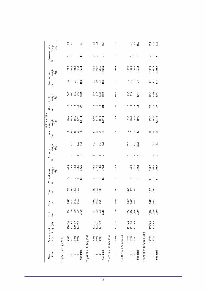
52
Cat
ch b
y sp
ecie
sN
umbe
rH
ook
Tim
eT
ime
of s
ets
Lat
. (S)
Lon
g. (
W)
Nos
.se
tha
ulN
o.W
eigh
tN
o.W
eigh
tN
o.W
eigh
tN
o.W
eigh
tN
o.W
eigh
tN
o.W
eigh
t(k
g)(k
g)(k
g)(k
g)(k
g)(k
g)
Tri
p 5:
3 t
o 8
July
200
0
113
° 09
'17
0° 5
4'73
006
4015
003
48.4
712
4.4
854
.718
227.
53
6.7
213
° 10
'17
1° 0
5'73
007
0015
101
24.8
464
.416
288.
62
10.7
2338
8.5
345
.23
13°
02'
170°
59'
730
0700
1500
388
.216
288.
24
55.2
2343
1.6
413
° 02
'17
1° 0
8'73
006
5015
355
164.
11
15.0
2545
0.4
1388
.344
717.
8Su
b-to
tal
2,92
012
325.
55
79.4
641,
151.
627
208.
910
81,
765.
46
51.9
Tri
p 6:
10
to 1
4 Ju
ly 2
000
113
° 01
'17
1° 1
2'73
506
4015
152
85.0
144
.014
260.
05
84.0
2247
3.0
345
.92
13°
02'
171°
25'
735
0650
1500
727
7.0
2647
4.0
657
.039
808.
01
1.1
313
° 00
'17
1° 3
0'73
506
3015
154
114.
01
28.0
2441
7.0
1312
8.5
4268
7.5
Sub-
tota
l2,
205
1347
6.0
272
.064
1,15
1.0
2426
9.5
103
1,96
8.5
447
.0
Tri
p 7:
18
to 2
0 Ju
ly 2
000
113
° 08
'17
1° 4
6'73
006
3515
101
15.0
575
.021
136.
427
226.
42
2.7
Tri
p 8:
4 t
o 8
Aug
ust
2000
112
° 26
'17
1° 4
6'1,
050
0610
1440
395
.84
65.3
225
.59
186.
62
12°
24'
171°
56'
1,15
009
2017
003
99.8
713
0.0
853
.618
283.
42
4.4
312
° 50
'17
2° 0
0'1,
100
0800
1550
131
.01
14.0
115
.04
27.3
787
.32
5.6
Sub-
tota
l3,
300
413
0.8
410
9.8
1221
0.3
1410
6.4
3455
7.3
410
.0
Tri
p 9:
10
to 1
4 A
ugus
t 20
00
113
° 26
'17
3° 0
5'1,
100
0640
1545
1123
4.7
4985
9.1
2219
3.1
821,
286.
94
35.1
213
° 28
'17
3° 0
5'1,
200
0800
1710
364
.22
8.2
4171
5.4
1520
6.6
6199
4.4
232
.2Su
b-to
tal
2,30
014
298.
92
8.2
901,
574.
537
399.
714
32,
281.
36
67.3
App
rox.
pos
itio
nY
ello
wfi
n tu
naB
igey
e tu
naA
lbac
ore
tuna
Oth
er s
alea
ble
Tot
al s
alea
ble
Uns
alea
ble
catc
h
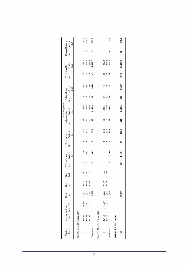
53
Cat
ch b
y sp
ecie
sN
umbe
rH
ook
Tim
eT
ime
of s
ets
Lat
. (S)
Lon
g. (
W)
Nos
.se
tha
ulN
o.W
eigh
tN
o.W
eigh
tN
o.W
eigh
tN
o.W
eigh
tN
o.W
eigh
tN
o.W
eigh
t(k
g)(k
g)(k
g)(k
g)(k
g)(k
g)
Tri
p 10
: 15
to
19 A
ugus
t 20
00
113
° 05
'17
0° 5
9'1,
100
0625
1520
115
.01
5.2
2340
8.9
810
5.4
3353
4.5
150
.02
13°
04'
171°
07'
1,20
006
5015
506
93.3
120
.430
552.
98
305.
245
971.
84
149.
73
13°
03'
171°
13'
420
0700
1720
1629
7.0
834
.424
331.
4Su
b-to
tal
2,72
07
108.
32
25.6
691,
258.
824
445.
010
21,
837.
75
199.
7
Tri
p 11
: 21
to
24 A
ugus
t 20
00
112
° 53
'17
1° 2
6'1,
200
0640
1550
127
.213
233.
514
71.7
2833
2.4
212
° 55
'17
1° 3
1'1,
200
0640
1545
119
.89
175.
012
63.4
2225
8.2
Sub-
tota
l2,
400
00.
02
47.0
2240
8.5
2613
5.1
5059
0.6
00.
0
TO
TA
L f
or t
he 1
1 tr
ips
3025
,055
223
4,14
2.1
2648
2.9
544
9,53
2.5
277
2,68
0.7
1,07
016
,838
.260
660.
0
Oth
er s
alea
ble
Tot
al s
alea
ble
Uns
alea
ble
catc
hA
ppro
x. p
osit
ion
Yel
low
fin
tuna
Big
eye
tuna
Alb
acor
e tu
na

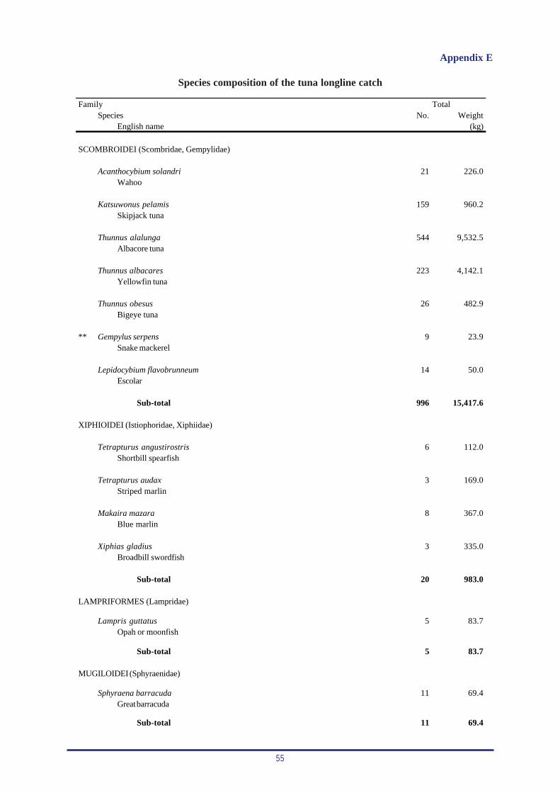
55
Appendix E
Species composition of the tuna longline catch
FamilySpecies No. Weight
English name (kg)
SCOMBROIDEI (Scombridae, Gempylidae)
Acanthocybium solandri 21 226.0Wahoo
Katsuwonus pelamis 159 960.2Skipjack tuna
Thunnus alalunga 544 9,532.5Albacore tuna
Thunnus albacares 223 4,142.1Yellowfin tuna
Thunnus obesus 26 482.9Bigeye tuna
** Gempylus serpens 9 23.9Snake mackerel
Lepidocybium flavobrunneum 14 50.0Escolar
Sub-total 996 15,417.6
XIPHIOIDEI (Istiophoridae, Xiphiidae)
Tetrapturus angustirostris 6 112.0Shortbill spearfish
Tetrapturus audax 3 169.0Striped marlin
Makaira mazara 8 367.0Blue marlin
Xiphias gladius 3 335.0Broadbill swordfish
Sub-total 20 983.0
LAMPRIFORMES (Lampridae)
Lampris guttatus 5 83.7Opah or moonfish
Sub-total 5 83.7
MUGILOIDEI (Sphyraenidae)
Sphyraena barracuda 11 69.4Great barracuda
Sub-total 11 69.4
Total
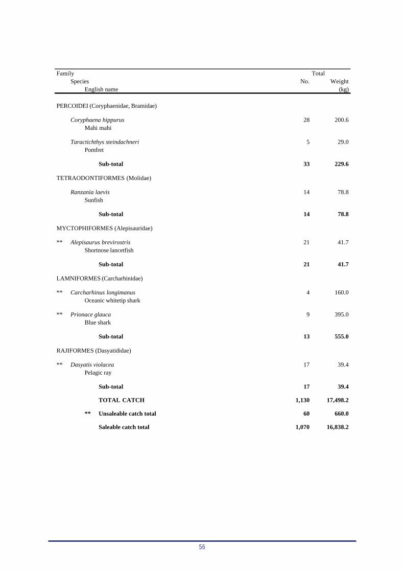
56
FamilySpecies No. Weight
English name (kg)
PERCOIDEI (Coryphaenidae, Bramidae)
Coryphaena hippurus 28 200.6Mahi mahi
Taractichthys steindachneri 5 29.0Pomfret
Sub-total 33 229.6
TETRAODONTIFORMES (Molidae)
Ranzania laevis 14 78.8Sunfish
Sub-total 14 78.8
MYCTOPHIFORMES (Alepisauridae)
** Alepisaurus brevirostris 21 41.7Shortnose lancetfish
Sub-total 21 41.7
LAMNIFORMES (Carcharhinidae)
** Carcharhinus longimanus 4 160.0Oceanic whitetip shark
** Prionace glauca 9 395.0Blue shark
Sub-total 13 555.0
RAJIFORMES (Dasyatididae)
** Dasyatis violacea 17 39.4Pelagic ray
Sub-total 17 39.4
TOTAL CATCH 1,130 17,498.2
** Unsaleable catch total 60 660.0
Saleable catch total 1,070 16,838.2
Total
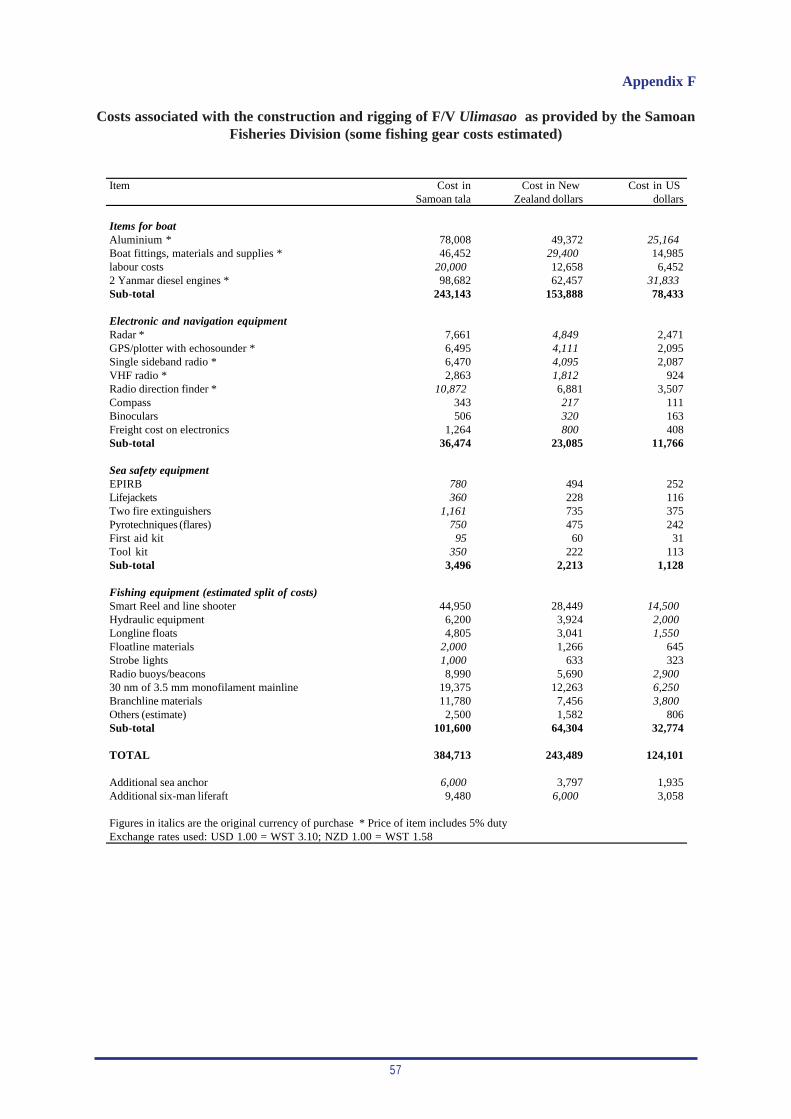
57
Item Cost in Cost in New Cost in USSamoan tala Zealand dollars dollars
Items for boatAluminium * 78,008 49,372 25,164Boat fittings, materials and supplies * 46,452 29,400 14,985labour costs 20,000 12,658 6,4522 Yanmar diesel engines * 98,682 62,457 31,833Sub-total 243,143 153,888 78,433
Electronic and navigation equipmentRadar * 7,661 4,849 2,471GPS/plotter with echosounder * 6,495 4,111 2,095Single sideband radio * 6,470 4,095 2,087VHF radio * 2,863 1,812 924Radio direction finder * 10,872 6,881 3,507Compass 343 217 111Binoculars 506 320 163Freight cost on electronics 1,264 800 408Sub-total 36,474 23,085 11,766
Sea safety equipmentEPIRB 780 494 252Lifejackets 360 228 116Two fire extinguishers 1,161 735 375Pyrotechniques (flares) 750 475 242First aid kit 95 60 31Tool kit 350 222 113Sub-total 3,496 2,213 1,128
Fishing equipment (estimated split of costs)Smart Reel and line shooter 44,950 28,449 14,500Hydraulic equipment 6,200 3,924 2,000Longline floats 4,805 3,041 1,550Floatline materials 2,000 1,266 645Strobe lights 1,000 633 323Radio buoys/beacons 8,990 5,690 2,90030 nm of 3.5 mm monofilament mainline 19,375 12,263 6,250Branchline materials 11,780 7,456 3,800Others (estimate) 2,500 1,582 806Sub-total 101,600 64,304 32,774
TOTAL 384,713 243,489 124,101
Additional sea anchor 6,000 3,797 1,935Additional six-man liferaft 9,480 6,000 3,058
Figures in italics are the original currency of purchase * Price of item includes 5% dutyExchange rates used: USD 1.00 = WST 3.10; NZD 1.00 = WST 1.58
Appendix F
Costs associated with the construction and rigging of F/V Ulimasao as provided by the SamoanFisheries Division (some fishing gear costs estimated)

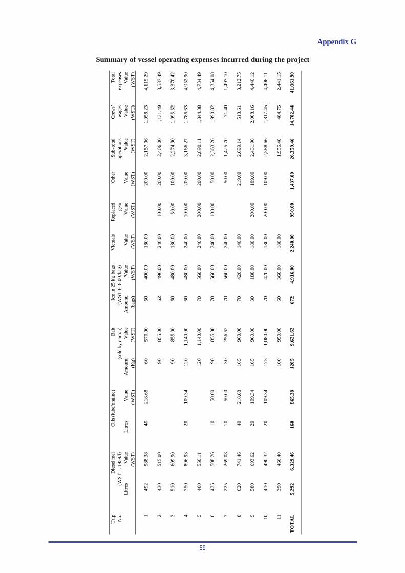
59
Appendix G
Summary of vessel operating expenses incurred during the project
Tri
pV
ictu
als
Rep
lace
dO
ther
Sub-
tota
lC
rew
s'T
otal
No.
gear
oper
atio
nsw
ages
expe
nses
Litr
esV
alue
Litr
esV
alue
Am
ount
Val
ueA
mou
ntV
alue
Val
ueV
alue
Val
ueV
alue
Val
ueV
alue
(WS
T)
(WS
T)
(Kg)
(WS
T)
(bag
s)(W
ST
)(W
ST
)(W
ST
)(W
ST
)(W
ST
)(W
ST
)(W
ST
)
149
258
8.38
4021
8.68
6057
0.00
5040
0.00
180.
0020
0.00
2,15
7.06
1,95
8.23
4,11
5.29
243
051
5.00
9085
5.00
6249
6.00
240.
0010
0.00
200.
002,
406.
001,
131.
493,
537.
49
351
060
9.90
9085
5.00
6048
0.00
180.
0050
.00
100.
002,
274.
901,
095.
523,
370.
42
475
089
6.93
2010
9.34
120
1,14
0.00
6048
0.00
240.
0010
0.00
200.
003,
166.
271,
786.
634,
952.
90
546
055
0.11
120
1,14
0.00
7056
0.00
240.
0020
0.00
200.
002,
890.
111,
844.
384,
734.
49
642
550
8.26
1050
.00
9085
5.00
7056
0.00
240.
0010
0.00
50.0
02,
363.
261,
990.
824,
354.
08
722
526
9.08
1050
.00
3025
6.62
7056
0.00
240.
0050
.00
1,42
5.70
71.4
01,
497.
10
862
074
1.46
4021
8.68
165
960.
0070
420.
0014
0.00
219.
002,
699.
1451
3.61
3,21
2.75
958
069
3.62
2010
9.34
165
960.
0030
180.
0018
0.00
200.
0010
9.00
2,43
1.96
2,00
8.16
4,44
0.12
1041
049
0.32
2010
9.34
175
1,08
0.00
7042
0.00
180.
0020
0.00
109.
002,
588.
661,
817.
454,
406.
11
1139
046
6.40
100
950.
0060
360.
0018
0.00
1,95
6.40
484.
752,
441.
15
TO
TA
L5,
292
6,32
9.46
160
865.
3812
059,
621.
6267
24,
916.
002,
240.
0095
0.00
1,43
7.00
26,3
59.4
614
,702
.44
41,0
61.9
0
(WS
T 1
.195
9/l)
(WST
6–8
.00/
bag)
(sol
d by
car
ton)
Die
sel f
uel
Oils
(lub
e/en
gine
)B
ait
Ice
in 2
5 kg
bag
s

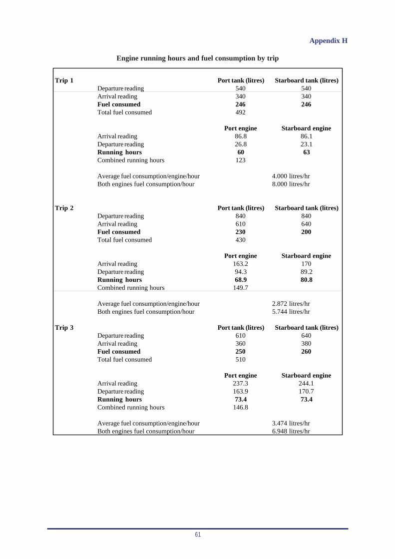
61
Appendix H
Engine running hours and fuel consumption by trip
Trip 1 Port tank (litres) Starboard tank (litres)Departure reading 540 540Arrival reading 340 340Fuel consumed 246 246Total fuel consumed 492
Port engine Starboard engineArrival reading 86.8 86.1Departure reading 26.8 23.1Running hours 60 63Combined running hours 123
Average fuel consumption/engine/hour 4.000 litres/hrBoth engines fuel consumption/hour 8.000 litres/hr
Trip 2 Port tank (litres) Starboard tank (litres)Departure reading 840 840Arrival reading 610 640Fuel consumed 230 200Total fuel consumed 430
Port engine Starboard engineArrival reading 163.2 170Departure reading 94.3 89.2Running hours 68.9 80.8Combined running hours 149.7
Average fuel consumption/engine/hour 2.872 litres/hrBoth engines fuel consumption/hour 5.744 litres/hr
Trip 3 Port tank (litres) Starboard tank (litres)Departure reading 610 640Arrival reading 360 380Fuel consumed 250 260Total fuel consumed 510
Port engine Starboard engineArrival reading 237.3 244.1Departure reading 163.9 170.7Running hours 73.4 73.4Combined running hours 146.8
Average fuel consumption/engine/hour 3.474 litres/hrBoth engines fuel consumption/hour 6.948 litres/hr
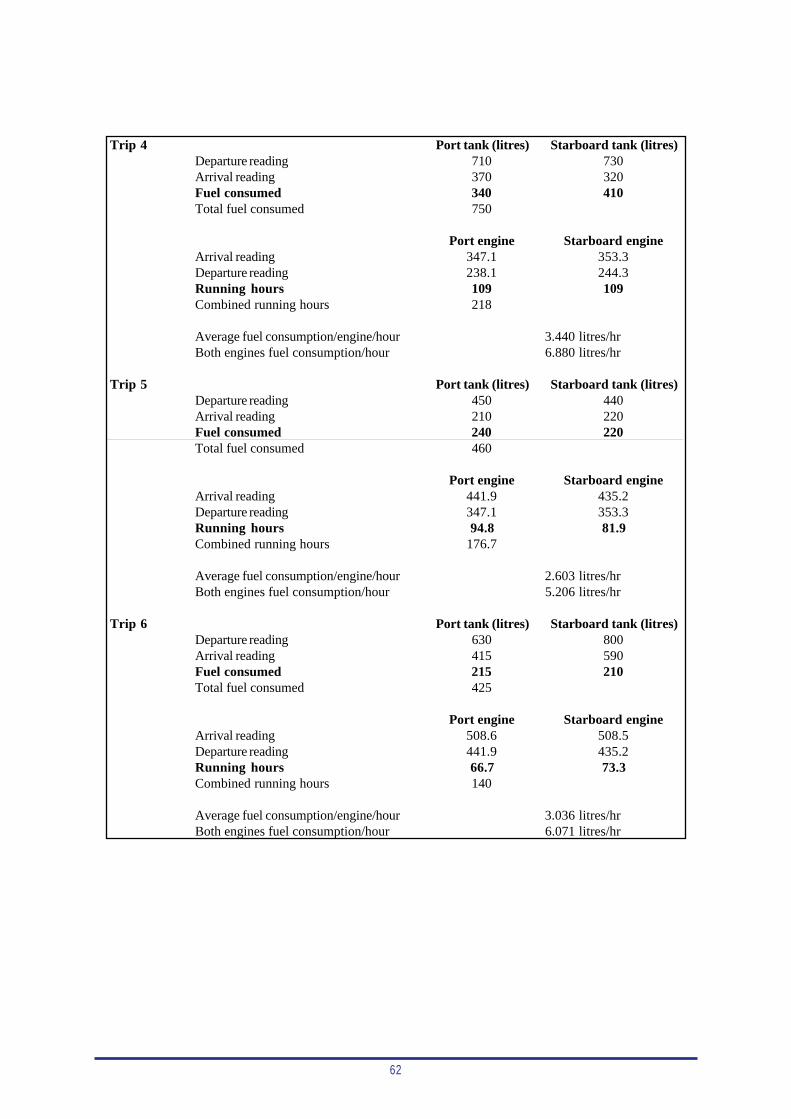
62
Trip 4 Port tank (litres) Starboard tank (litres)Departure reading 710 730Arrival reading 370 320Fuel consumed 340 410Total fuel consumed 750
Port engine Starboard engineArrival reading 347.1 353.3Departure reading 238.1 244.3Running hours 109 109Combined running hours 218
Average fuel consumption/engine/hour 3.440 litres/hrBoth engines fuel consumption/hour 6.880 litres/hr
Trip 5 Port tank (litres) Starboard tank (litres)
Departure reading 450 440Arrival reading 210 220Fuel consumed 240 220Total fuel consumed 460
Port engine Starboard engineArrival reading 441.9 435.2Departure reading 347.1 353.3Running hours 94.8 81.9Combined running hours 176.7
Average fuel consumption/engine/hour 2.603 litres/hrBoth engines fuel consumption/hour 5.206 litres/hr
Trip 6 Port tank (litres) Starboard tank (litres)Departure reading 630 800Arrival reading 415 590Fuel consumed 215 210Total fuel consumed 425
Port engine Starboard engineArrival reading 508.6 508.5Departure reading 441.9 435.2Running hours 66.7 73.3Combined running hours 140
Average fuel consumption/engine/hour 3.036 litres/hrBoth engines fuel consumption/hour 6.071 litres/hr
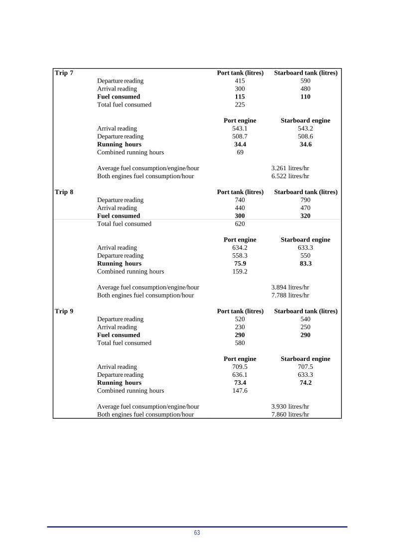
63
Trip 7 Port tank (litres) Starboard tank (litres)Departure reading 415 590Arrival reading 300 480Fuel consumed 115 110Total fuel consumed 225
Port engine Starboard engineArrival reading 543.1 543.2Departure reading 508.7 508.6Running hours 34.4 34.6Combined running hours 69
Average fuel consumption/engine/hour 3.261 litres/hrBoth engines fuel consumption/hour 6.522 litres/hr
Trip 8 Port tank (litres) Starboard tank (litres)Departure reading 740 790Arrival reading 440 470Fuel consumed 300 320Total fuel consumed 620
Port engine Starboard engineArrival reading 634.2 633.3Departure reading 558.3 550Running hours 75.9 83.3Combined running hours 159.2
Average fuel consumption/engine/hour 3.894 litres/hrBoth engines fuel consumption/hour 7.788 litres/hr
Trip 9 Port tank (litres) Starboard tank (litres)Departure reading 520 540Arrival reading 230 250Fuel consumed 290 290Total fuel consumed 580
Port engine Starboard engineArrival reading 709.5 707.5Departure reading 636.1 633.3Running hours 73.4 74.2Combined running hours 147.6
Average fuel consumption/engine/hour 3.930 litres/hrBoth engines fuel consumption/hour 7.860 litres/hr
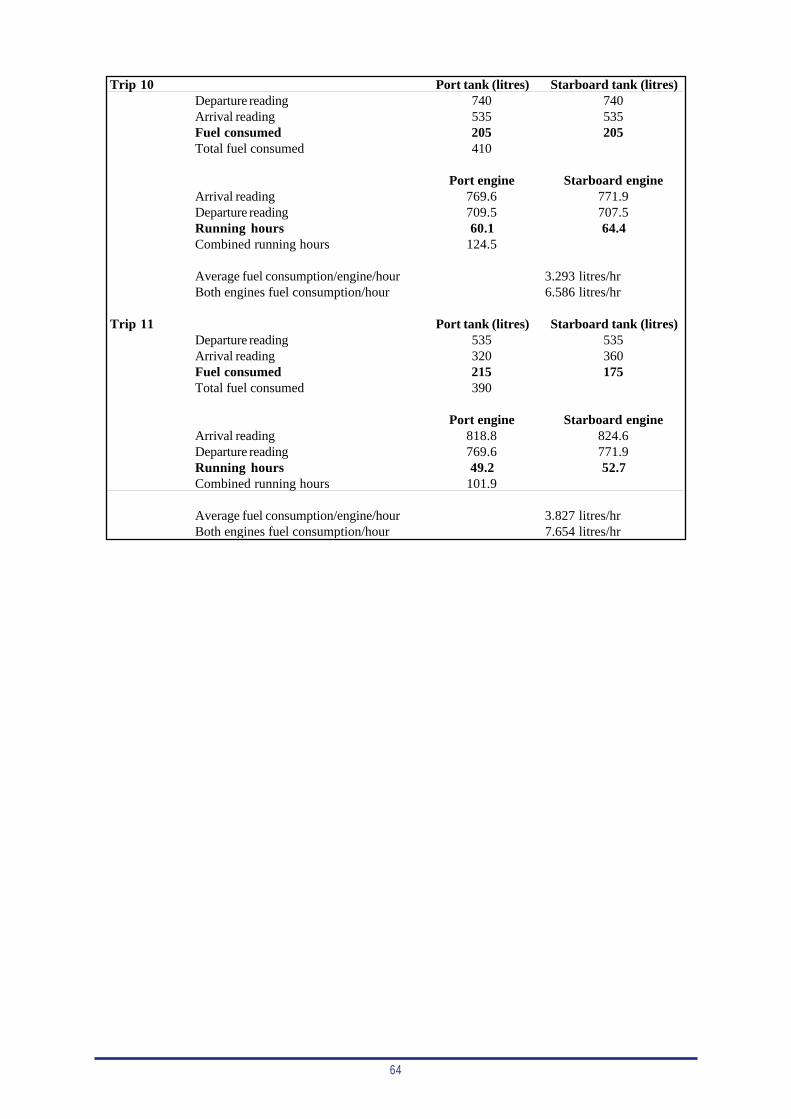
64
Trip 10 Port tank (litres) Starboard tank (litres)Departure reading 740 740Arrival reading 535 535Fuel consumed 205 205Total fuel consumed 410
Port engine Starboard engineArrival reading 769.6 771.9Departure reading 709.5 707.5Running hours 60.1 64.4Combined running hours 124.5
Average fuel consumption/engine/hour 3.293 litres/hrBoth engines fuel consumption/hour 6.586 litres/hr
Trip 11 Port tank (litres) Starboard tank (litres)Departure reading 535 535Arrival reading 320 360Fuel consumed 215 175Total fuel consumed 390
Port engine Starboard engineArrival reading 818.8 824.6Departure reading 769.6 771.9Running hours 49.2 52.7Combined running hours 101.9
Average fuel consumption/engine/hour 3.827 litres/hrBoth engines fuel consumption/hour 7.654 litres/hr