Embed Size (px)
Citation preview
The Islamic University of Gaza
Deanery of Graduate Studies
Faculty of Engineering
Department of Electrical Engineering
�
�������������������� �� ���� ����� ������������ �
������������������ ������������ �� �����
����������
by
Sami Ahmed Abu Ishaiba
Supervisor�
�������������� � ��
�
������������ ��
A Thesis Submitted In Partial Fulfillment Of The Requirements For The Degree Of
Master In Engineering
����

�������������� ��������
��������������������
������������
�������������
������������ ���������������������������� ��� !"#$�%!&$��' (�����)���* +,-�
��������������� ��������������������������������������������
��� !
��"# �$%����������
&��'!
�.("'�)�$����*���
� .+�$ ���*�
��������������– �+,-%
2012

�������������������
��)������ �� ���� ��� � ��� �� �� ��� � ���� �� ���� ���� �� �� ��������� �� ��� ���� ��(
������������ �
� �
� �
� �

i
� �� ������� �� �
������������� ����� �
�������������������������� �
������� !"####� �
� �
� �
� �
� �
� �
� � �
ii
Acknowledgements
In the name of Allah the most Compassionate and the most Merciful, who has
favored me with countless blessings. May Allah accept our good deeds and forgive
our shortcomings.
I would like to offer my heartfelt thanks to my advisor Prof Dr. Mohammed
Shabat and Dr.khitam El wasife who provided me with support and scientific
assistants during the thesis and always welcomed my questions with the best possible
guidance, hints and helps. His passion for research and knowledgeable suggestions
have greatly enhanced my enjoyment of this process, and significantly improved the
quality of my research work.
I also hereby offer my special gratitude to Dr. Mohamed Oda and Dr. Fadi
Alnahal my examiners and teachers. I would also like to thank my colleagues and
friends in the taught master semesters for their warm friendship during these years.
I would like to thanks my uncle Fays Elhegy, who support me and my close
friends Ammar Altater, Hazem Abu Karsh and Mohmad Madi.
Last, my most sincere thanks go to my beloved father and Special thanks to my wife
for her support, patience and prayers which accompanied me all the way along.
Also I would like to thank my brothers. And thanks to my dear sisters and all
my precious family
� �
� �
� �
iii
Abstract
The rapid diffusion of wireless communication systems such as cellular
phones and wireless local area networks has caused an increased concern for the
potential detrimental effect on human health deriving from exposure to EM fields
emitted by the antennas of these systems.
In particular, with reference to cellular telecommunication systems, two
different exposure condition are present. The first is the exposure of the user's
head to the portable phone and the second is the general population exposure to the
field radiated by the base station antennas,�the researcher in this study will discuss the
general population exposure to the field radiated by the base station antennas.
In this study, the exposure of an anatomical model of the human head
represented by (skin-bone-brain) to the field radiated by a base station antenna
operating around 900MHz has been studied by using the matlab program and FDTD
technique.
Numerical method such as FDTD method has been used to study theoretically
the biological effect of electromagnetic waves produced from mobile phone base
station on human head life tissue.
Specific Absorption Rate(SAR) ,electric and magnetic field has been drawn with
respect to time steps ; according to this study the SAR in skin and bone is higher than
in other tissue.
iv
���������
������� ����������������������������� !"#��$��%&��'� (���)*� ����+&�,��-��./�
�"0#��1�������$���234%�44�#"���1�5������ 6��7���1�5���8�9�!79��46��7���:�
7���!";��'��1�<7���54:��(*=�>6�� �� �?�=����4-@��A� 1��� 1�����)*� -��./��"BC&! ����
!78��D1�<7���E?):�+&�,�� =��3/�.
!��@��&�?�=��3/�F�@��D��"G�,H�4�'#��6�I����"BC& +��3�(������6$�:�Matlab ��@4
6��7���(!8����!";��'��. �2���4��I���)41�JKGL$B��D!"�"G�,H�4�'#��1�5�����"BC&!��@��&
J��M"�:����N�:D%����!JKGO>�"BC&=�M"�P�����4Q�9��*�6���4 �.
4�R46�7&O�S(!"7����$�����D�B��O��<���,�T���������D!"�"G�,H�4�'#��1�5����U�����=��5
!"�"G�,H�4�'#��1�5����:�V<�K�!��@�WX4�&V3�M"�!�@������!"�"G�,H�4�'#��1�5����
64N�O9S��� !������1*�9&*�1�<7�:D!I&�,��1�5����4�'9;�9�4
�� �3�0��O9S� @�9(!"�"G�,H�4�'#��1�5����:D+&�,���5���"K���"BC���:DV���.!��@�WX4�&
�2���4��I���)4F����:�1�JKGL$B��D�)�B�Y"X�&�&4����7&F����4��I����D�)�"BC&4V<�K�
Z�[��D!K&�����@�B\��)��4P�������$�4.
M��0��O9S����� �&:�T��(!J������!"�"G�,H�4�'#��1�5����W���&!J��G41�";��'��-��3�64�,&V".
�D�,��Q�9��*�6���:"K&!"3�"(1�R$D��@�&]$&����+��3�(������6$�:�4SARU�����6$�
��@�&!,"��!",��1��� 6$�6��7���1�<7�:� @��9��!"�"G�,H�4�'#��1�5�����(�'#��6�I���
Q�9��*���D @�J��4��"G�,H���.
P������'"��4��I���)!"�"G�,H�4�'#��1�5�����8�9���1�JK<���0>�=�:"K&1�",7,���!��@�6$�:�.
v
���������
Page No. CHAPTER ONE
Electromagnetic waves And Antenna properties
Introduction ……………………………………..………………..…................... 1
1.1 Electromagnetic Wave…………………………………………..…………..… 1
1.2 Electromagnetic Frequency Spectrum……………………………………..…...2
1.2.1 The Radio Frequency (RF) Standards………..………………..……. 2
1.2.2 Electromagnetic Emitted From Mobile Phone…………………….... 2
1.2.3 Types of Electromagnetic Radiation…………..…………………..... 3
1.3 Electromagnetic Wave Properties …………………………..………………..... 3
1.4 Mobile Phone Network……………………….……………….……………..... 4
1.4.1Cellular System………………………………………………………4
1.4.2 Base Stations………………..…………………………………………4
1.4.3 How a Cellular System Works…………….……..………………….. 5
1.5 Antenna………………………………………………………………..………. 5
1.5.1 Antenna Properties……………………….………………………….………. 5
1.6 Types of Antennas………………………..………………….…...…………... 11
1.6.1 Directional Antennas…………………………...……………….…………... 11
1.6.1.1 Sector Antenna……………………………………………………...………11
1.7 Physics of Mobile Telephony…………………….………….……………… 13
1.8Principle of Cellular Radio Network…………………..…………………....…..13
1.9 General Effect of Radio Frequency Radiation (Base Station)………..…...…. 14
���� ������
Brief Review of interaction of EM waves with Biological Tissue.
2.1 Introduction……………………………………………………..……………... 15
2.2 Human Body Structure…………………………………………..…………….. 16
2.2.1 Skin Tissue………………………………………………………....... 16
2.2.2 Bones……………………………………………………………….. 16
2.2.2.1 Bones……………………………….…………………....... 17
2.2.2.2 Skull…………………………………..………………........ 17
vi
2.2.3 Brain……………………………………..………………………...... 17
2.3 Radiation Absorption………………………………………………………...... 18
2.4 Rate of Absorption of The Human Head To Radiation ………….………...... 20
2.5 Biological Effects of Mobile Phone Radiation………………….……....…..... 21
2.5.1 Thermal Effect………………………………………..….............. 21
2.5.2 Non Thermal Effects Non-thermal …………………………..….. 21
2.5.3Biological Changes…………………………………..…………… 22
2.6 Cancer…………………………………………………………………..……... 24
2.7Conclusion…………………………………………………………………..…. 27
���� ��� ���
Maxwell’s Equations And Finite Difference Time Domain (FDTD)
Introduction……………………………………………………………….……..... 29
3.1 Finite-Difference Time-Domain (FDTD)………………………..……………. 29
3.1.1 Finite-Difference Time-Domain (FDTD)………..…………..…….….29
3.1.2 Using the FDTD Method………………………………………….… 30
3.1.3 Workings of the FDTD method………….……………………….... 30
3.1.4 FDTD Formulation……………………………….………….……... 32
3.2.1 Maxwell's Equations……………………………………………………...…. 32
3.2.2 Theory and Model………………………………………………....33
3.2.3 FDTD Method and Maxwell's Equations…………………………….…34
3.2.4 Curl Equations in Cartesian Coordinates…………………………...…36
3.2.5 1D-FDTD Solution to Maxwell’s Equations ……….……………...…37
3.2.6 Propagation Simulate in Media that have Conductivity ………….…39
vii
���� ����� �
The Results and Analysis
Introduction ………………………………………..………………………. .......... 42
4.1 Results and Discussion……………………………………………….…………42
4.2 One-Dimensional Simulation with the FDTD Method………….……………. 45
4.3 Two-Dimensional Simulation with the FDTD Method………………………. 52
4.4 Three-Dimensional Simulation with the FDTD Method………………………. 54
4.5 Discussion.......……………………….……………………...... ....................... 72
4.5.1 One-Dimensional Simulation with the FDTD.… ………………...... 72
4.5.2 Three-Dimensional Simulation with the FDTD.… ……………........ 73
�
����������
Results
5.1 Result and Discussion……………………….……………………….............. 75
5.1.1 One-Dimensional Simulation with the FDTD Method……….......... 75
5.1.2 Three-Dimensional Simulation with the FDTD Method………........ 75
5.2 Conclusion…………………………………………………..………………... 76
5.3 Future work………………………………………………………….………... 76
Reference…………………………………………………………..…………...... 77
viii
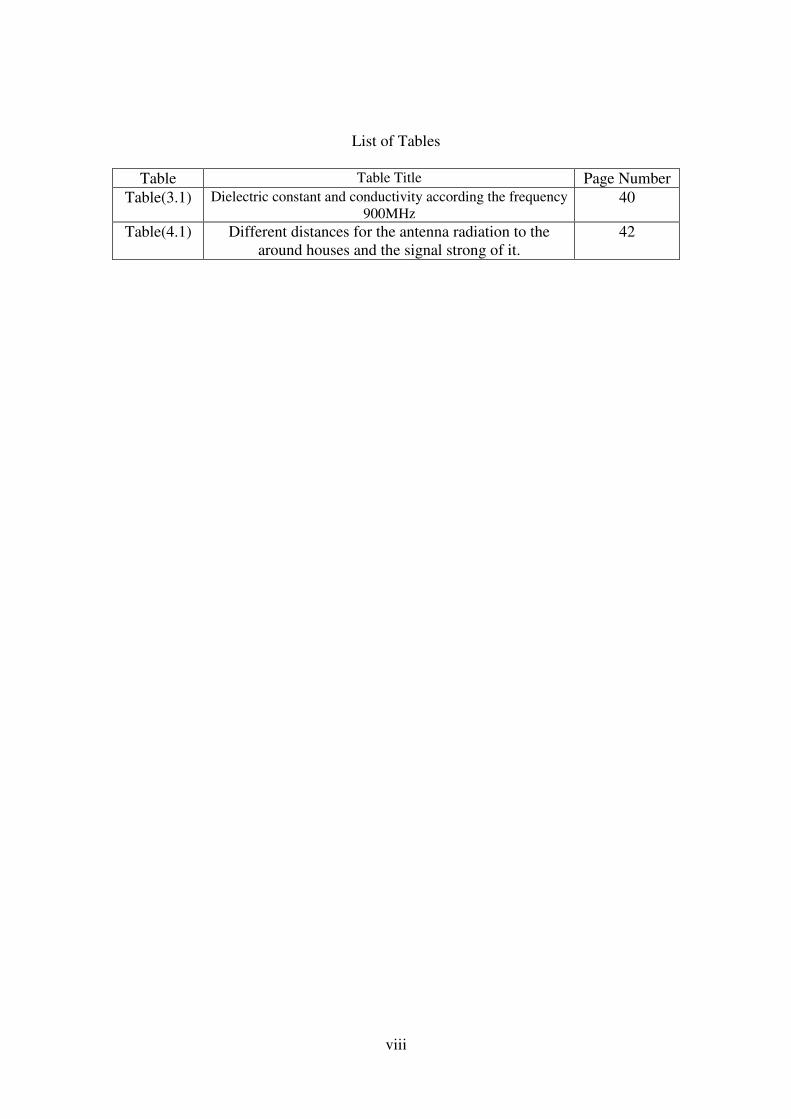
List of Tables
Page Number Table Title Table
40 Dielectric constant and conductivity according the frequency
900MHz Table(3.1)
42 Different distances for the antenna radiation to the
around houses and the signal strong of it.
Table(4.1)
ix
List of Figures
Page
number
Title of figures Figures
2 Electromagnetic radiation frequency spectrum Figure(1.1)
3 Electric and magnetic plane Figure(1.2)
6 Radiation pattern Figure(1.3)
7 Rotation of a plane electromagnetic wave and its
polarization ellipse at z=0 as a function of time
Figure(1.4)
12 Typical GSM sector antenna outdoor unit Figure(1.5)
12 Horizontal and vertical radiation patterns Figure(1.6)
12 Sector antenna installed on a short mast Figure(1.7)
13 Lightning rods that found on supporting construction Figure(1.8)
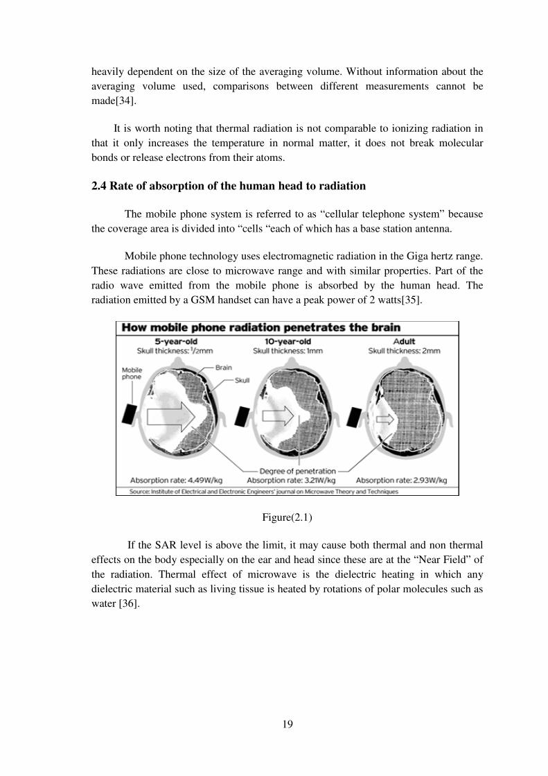
19 How mobile phone radiation penetrate the brain Figure(2.1)
20 Thermo graphic image of the head with no exposure to
harmful cell phone radiation Figure(2.2)
20 Thermo graphic image of the head after a 15 minute phone
call Figure(2.3)
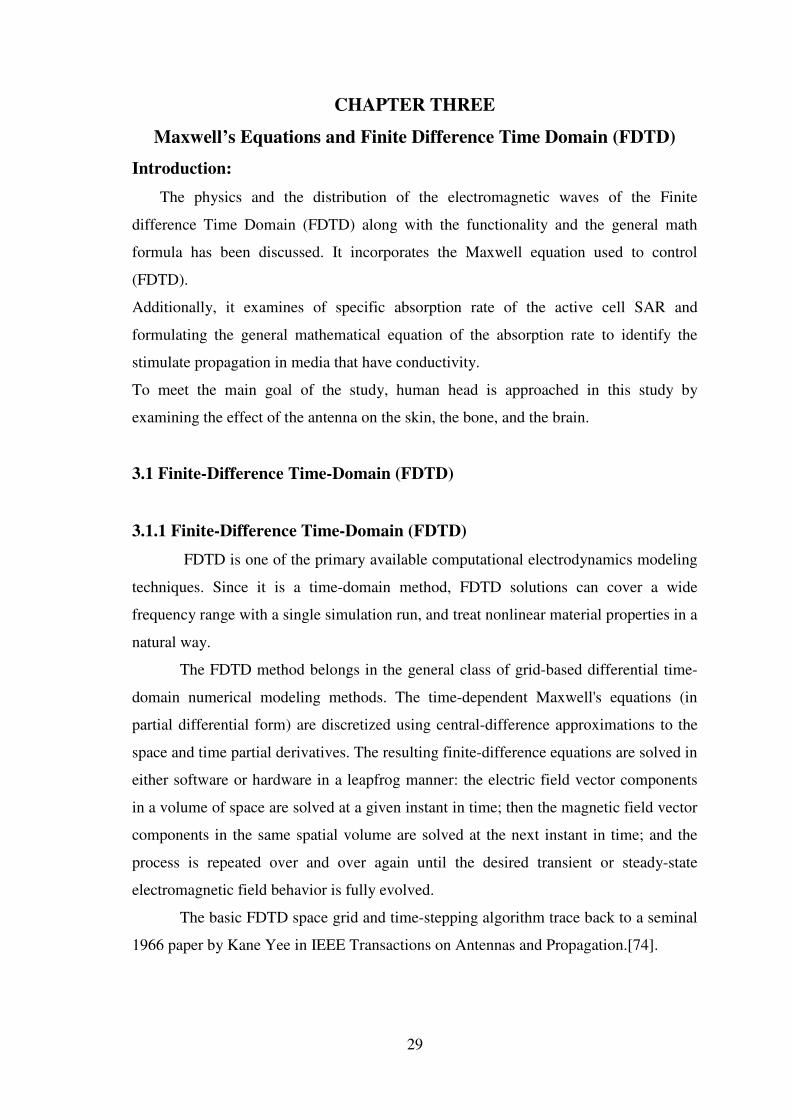
31 Illustration of a standard Cartesian Yee cell used for FDTD,
about which electric and magnetic field vector components
are distributed.
Figure(3.1)
34 Model of layered dielectric slab Figure(3.2)
45 Represent the relation between electric field and time steps
through human body at distance 11m Figure(4.1)
46 Represent the relation between magnetic field and time steps
through human body at distance 11m.
Figure(4.2)
46 Represent the relation between power density and time steps
through human body at distance 11m Figure(4.3)
47 Represent the relation between SAR and time steps through
human body at distance 11m Figure(4.4)
48 Represent the relation between electric field and time steps
through human body at distance 13m Figure(4.5)
48 Represent the relation between magnetic field and time steps
through human body at distance 13m Figure(4.6)
49 Represent the relation between power and time steps
through human body at distance 13m Figure(4.7)
49 Represent the relation between SAR and time steps through
human body at distance 13m Figure(4.8)
50 Represent the relation between electric field and time steps
through human body at distance 15m Figure(4.9)
50 Represent the relation between power density and time
steps through human body at distance 15m Figure(4.10)
51 Represent the relation between SAR and time steps through
human body at distance 15m Figure(4.11)
x
52 Represent the relation between electric field and time steps
through human body 2 dimensional at distance 11m Figure(4.12)
52 Represent the relation between electric field and time steps
through human body 2 dimensional at distance 13m Figure(4.13)
53 Represent the relation between electric field and time steps
through human body 2 dimensional at distance 15m Figure(4.14)
54 Represent the relation between electric field in free space
and time steps through human body 3 dimensional at
distance 11m
Figure(4.15)
54 Represent the relation between electric field in free space
and time steps through human body 3 dimensional at
distance 13m
Figure(4.16)
55 Represent the relation between electric field in free space
and time steps through human body 3 dimensional at
distance 15m
Figure(4.17)
55 Represent the relation between electric field in skin and time
steps through human body distance 11m Figure(4.18)
56 Represent the relation between electric field in skin and time
steps through human body distance 13m Figure(4.19)
56 Represent the Relation between electric field in skin and
time steps through human body distance 15m Figure(4.20)
57 Represent relation between electric field in bone cancellous
and time steps through human body at distance 13 m.
Figure (4.21)
57 Represent the relation between electric field in bone
cancellous and time steps through human body distance 13m Figure(4.22)
58 Represent the relation between electric field in bone
cancellous and time steps through human body distance 15m Figure(4.23)
58 Represent the relation between electric field in brain grey
matter and time steps through human body distance 11m Figure(4.24)
59 Represent the relation between electric field in and brain
grey matter time steps through human body distance 13m Figure(4.25)
59 Represent the relation between electric field in brain grey
matter and time steps through human body distance 15m Figure(4.26)
60 Represent the relation between power density in free matter
and time steps through human body distance 11m Figure(4.27)
60 Represent the relation between power density in free matter
and time steps through human body distance 13m Figure(4.28)
61 Represent the Relation between Power density in free
matter and time steps through human body distance 15m Figure(4.29)
61 Represent the relation between power density in skin and
time steps through human body distance 11m Figure(4.30)
62 Represent the relation between power density in skin and
time steps through human body distance 13m Figure(4.31)
62 Represent the relation between power density in skin and
time steps through human body distance 15m Figure(4.32)
63 Represent the relation between power density in bone
cancellous and time steps through human body distance 11m Figure(4.33)
63 Represent the relation between power density in bone
cancellous and time steps through human body distance 13m Figure(4.34)
64 Represent the relation between power density in bone
cancellous and time steps through human body distance 15m Figure(4.35)
64 Represent the relation between power density in brain grey
matter and time steps through human body distance 11m Figure(4.36)
xi
65 Represent the relation between power density in brain grey
matter and time steps through human body distance 13m Figure(4.37)
65 Represent the relation between power density in brain grey
matter and time steps in through human body distance
15m.
Figure(4.38)
66 Represent the relation between SAR in free space and time
steps through human body distance 11m&13m&15m Figure(4.39)
67 Represent the relation between SAR in skin dry and time
steps through human body distance 11m Figure(4.40)
67 Represent the relation between SAR in skin dry and time
steps through human body distance 13m Figure(4.41)
68 Represent the relation between SAR in skin dry and time
steps through human body distance 15m Figure(4.42)
68 Represent the relation between SAR in bone cancellous and
time steps through human body distance 11m Figure(4.43)
69 Represent the relation between SAR in bone cancellous and
time steps through human body distance 13m Figure(4.44)
69 Represent the relation between SAR in bone cancellous and
time steps through human body distance 15m Figure(4.45)
70 Represent the relation between SAR in brain grey matter
and time steps through human body distance 11m Figure(4.46)
70 Represent the relation between SAR in brain grey matter
and time steps through human body distance 13m Figure(4.47)
71 Represent the relation between SAR in brain grey matter
and time steps through human body distance 15m Figure(4.48)
xii
Abbreviation
UV: Ultra Violet Rays
RF: Radio Frequency
IEEE: The Institute Of Electrical And Electronics Engineers
ANSI: American National Standards Institute
MHz: Mega Hertz
ERP: Effective Radiation Power
W: Watt
FDTD: Finite Difference Time Domain
SAR: Specific Absorption Rate
MPa: Mega Pascal's
SCENIHR: Scientific Committee on Emerging and Newly Identified Health Risks
GSM: Global System for Mobile Communication
FCC: Federal Communications Commission .
GHz: Giga Hertz
BBB: Blood Brain Barrier
IARC: International Agency for Research On Cancer
ACRBR: The Australian Centre for Radio Frequency Bio effect Research
ICNIRP: International Commission for Non- Ionizing Radiation Protection.
HFSS: High Frequency Structure Simulator

1
CHAPTER ONE
Electromagnetic Waves and Antenna Properties
Introduction:
To talk about the radiations emitting from telecommunication stations, it is hard to
ignore examining the role of electromagnetic waves.
In this chapter, the researcher focuses on the origin of the electromagnetic waves, radio
frequencies, the frequencies used in wireless services, and the different kinds of
electromagnetic waves. The chapter also focuses on the feature of ionizing and non-
ionizing of these waves.
The researcher talk about the different kinds of antenna; including the frequencies of
emission with a 120 or 360 degree. Also, focuses on the directed-undirected antenna
along with studying the antenna used in the GSM system known as Sector Antenna,
this chapter also focuses on the communication cells and the transmission towers.
1.1 Electromagnetic wave
Electromagnetic waves are formed when there is a continuing process of an
electric field developing a magnetic field and vice versa. An electromagnetic wave has
both, electric as well as magnetic components. The production of magnetism due to
electric current is known as electromagnetism. The electromagnetic theory was
developed by James Maxwell, whereas Heinrich Hertz demonstrated electromagnetic
waves. The electrically charged particles, when in motion, created a magnetic field.
This gave rise to electromagnetic waves is observed.
The discovery of electromagnetic waves proved to be revolutionary as these
waves have various uses. These waves transmit energy in the form of X-rays, gamma
rays, UV rays and infrared radiation[1].
2
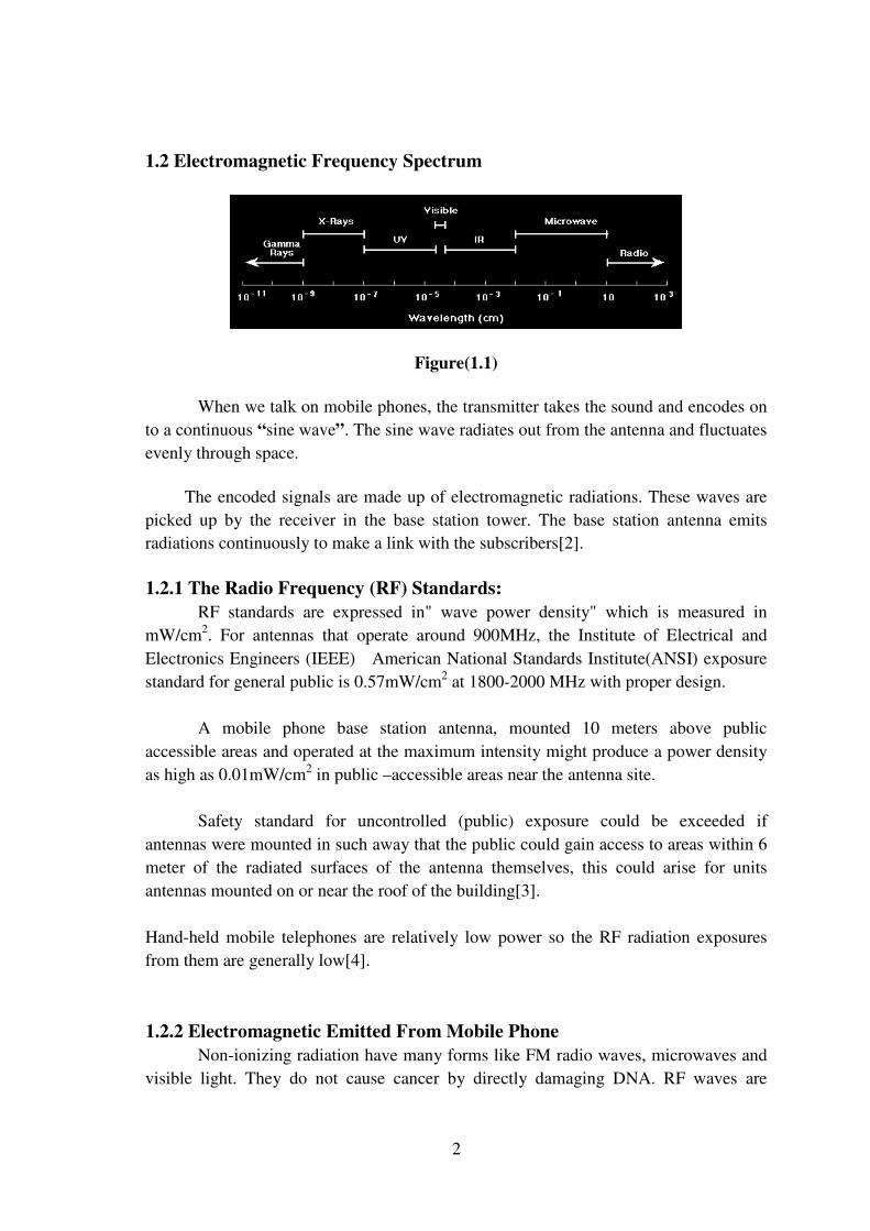
1.2 Electromagnetic Frequency Spectrum
Figure(1.1)
When we talk on mobile phones, the transmitter takes the sound and encodes on
to a continuous “sine wave”. The sine wave radiates out from the antenna and fluctuates
evenly through space.
The encoded signals are made up of electromagnetic radiations. These waves are
picked up by the receiver in the base station tower. The base station antenna emits radiations continuously to make a link with the subscribers[2].
1.2.1 The Radio Frequency (RF) Standards:
RF standards are expressed in" wave power density" which is measured in
mW/cm2. For antennas that operate around 900MHz, the Institute of Electrical and
Electronics Engineers (IEEE) American National Standards Institute(ANSI) exposure
standard for general public is 0.57mW/cm2 at 1800-2000 MHz with proper design.
A mobile phone base station antenna, mounted 10 meters above public
accessible areas and operated at the maximum intensity might produce a power density
as high as 0.01mW/cm2 in public –accessible areas near the antenna site.
Safety standard for uncontrolled (public) exposure could be exceeded if
antennas were mounted in such away that the public could gain access to areas within 6
meter of the radiated surfaces of the antenna themselves, this could arise for units
antennas mounted on or near the roof of the building[3].
Hand-held mobile telephones are relatively low power so the RF radiation exposures
from them are generally low[4].
1.2.2 Electromagnetic Emitted From Mobile Phone
Non-ionizing radiation have many forms like FM radio waves, microwaves and
visible light. They do not cause cancer by directly damaging DNA. RF waves are

3
different from stronger types of radiation such as x-rays, gamma rays, and ultraviolet
(UV) light, which can break the chemical bonds in DNA.
At very high levels, RF waves can heat up body tissues, however the levels of
energy given off by cell phones are much lower, and the warmth from a cell phone does
not damage body tissues[5].
All cell phones emit some amount of electromagnetic radiation. Given the close
proximity of the phone to the head, it is possible for the radiation to cause some sort of
harm to human head. What is being debated in the scientific and political arenas is just
how much radiation is considered unsafe, and if there are any potential long-term
effects of cell-phone radiation exposure[5].
1.2.3 Types of Electromagnetic Radiation:
• Ionizing radiation - This type of radiation contains enough electromagnetic energy
to strip atoms and molecules from the tissue and alter chemical. X- ray as example
of ionizing radiation which use in medicine can cause damage to body tissue ,so we
wear lead vest when x-ray are taken to ours body.
• Non-ionizing radiation - Non-ionizing radiation is typically safe. It causes some
heating effect, but usually not enough to cause any type of long-term damage to
tissue. Radio-frequency energy, visible light and microwave radiation are considered non-ionizing[6].
1.3 Electromagnetic Wave Properties
The electric field is in a vertical plane and the magnetic field is in a horizontal
plane. Electromagnetic waves can be imagined as a self-propagating transverse
oscillating wave of electric and magnetic fields. 3D diagram shows a plane polarized
wave propagating from left to right as shown in Fig (1.2).
Figure(1.2)
The physics of electromagnetic radiation is electrodynamics. Electromagnetism is
the physical phenomenon associated with the theory of electrodynamics. Electric and

4
magnetic fields obey the properties of superposition. Thus, a field due to any particular
particle or time-varying electric or magnetic field contributes to the fields present in the
same space due to other causes. Furthermore, as they are vector fields, all magnetic and
electric field vectors add together according to vector addition.
EM radiation exhibits both wave properties and particle properties at the same
time. Both wave and particle characteristics have been confirmed in a large number of experiments[7].
Wave characteristics are more apparent when EM radiation is measured over
relatively large timescales and over large distances while particle characteristics are
more evident when measuring small timescales and distances. For example, when
electromagnetic radiation is absorbed by matter, particle-like properties will be more
obvious when the average number of photons in the cube of the relevant wavelength is much smaller than one.
There are experiments in which the wave and particle natures of electromagnetic
waves appear in the same experiment, such as the self-interference of a single photon.
When a single photon is sent through an interferometer, it passes through both paths,
interfering with itself, as waves do, yet is detected by a photomultiplier or other sensitive detector only once[7].
1.4 Mobile phone network
1.4.1 Cellular system
Mobile communication networks are divided into geographic areas called cells,
each served by a base station, mobile phones are the user’s link to the network. The
system is planned to ensure that mobile phones maintain the link with the network as
users move from one cell to another. To communicate with each other, mobile phones
and base stations exchange radio signals. The level of these signals is carefully
optimized for the network to perform satisfactorily. They are also closely regulated to
prevent interference with other radio systems used; for example, by emergency services,
taxis as well as radio and television broadcasters[8].
1.4.2 Base Stations
Base stations are sometimes called control or fixed stations in US Federal
Communications Commission licensing. These terms are defined in regulations inside Part 90 of the commissions regulations. Types of base stations include:
• A fixed station is a base station used in a system intended only to communicate
with other base stations. A fixed station can also be radio link used to operate a

5
distant base station by remote control. (No mobile or hand-held radios are involved
in the system.)
• A control station is a base station used in a system with a repeater where the
base station is used to communicate through the repeater.
• A temporary base is a base station used in one location for less than a year.
• A repeater is a type of base station that extends the range of hand-held and mobile radios.
Base stations are broadly divided into the following categories according to cell size:-
• Macro cells – towers, masts and poles providing wide are coverage
• Micro cells – small antennas at street level providing local area coverage
• Pico cells – very small antennas providing dedicated coverage spots
In building systems small antennas inside a building providing dedicated
coverage[9].
1.4.3 How a cellular system works
Mobile phones
When a mobile phone is switched on, it responds to specific control signals from
nearby base stations. When it has found the nearest base station in the network to which
it subscribes, it initiates a connection. The phone will then remain dormant, just
occasionally updating with the network, until the user wishes to make a call or a call is
received.
Mobile phones use automatic power control as a means of reducing the
transmitted power to the minimum possible whilst maintaining good call quality. For
example, while using a phone the average power output can vary between the minimum
level of about 0.001 watt up to the maximum level which is less than 1 watt. This
feature is designed to prolong battery life and possible talk time[10].
1.5 Antenna
Antennae are wires that receive and conduct electromagnetic waves, typically to transmit information[11].
1.5.1Antenna properties:
The most important properties possessed by many antenna are polarization
,radiation pattern, power gain, radiation resistance, band width, effective aperture, power transfer and reciprocity.
6
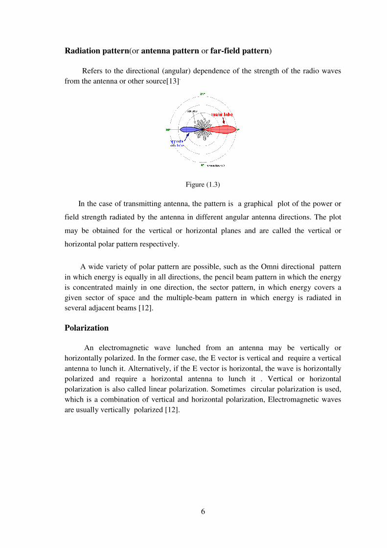
Radiation pattern(or antenna pattern or far-field pattern)
Refers to the directional (angular) dependence of the strength of the radio waves from the antenna or other source[13].
Figure (1.3)
In the case of transmitting antenna, the pattern is a graphical plot of the power or
field strength radiated by the antenna in different angular antenna directions. The plot
may be obtained for the vertical or horizontal planes and are called the vertical or
horizontal polar pattern respectively.
A wide variety of polar pattern are possible, such as the Omni directional pattern
in which energy is equally in all directions, the pencil beam pattern in which the energy
is concentrated mainly in one direction, the sector pattern, in which energy covers a
given sector of space and the multiple-beam pattern in which energy is radiated in several adjacent beams [12].
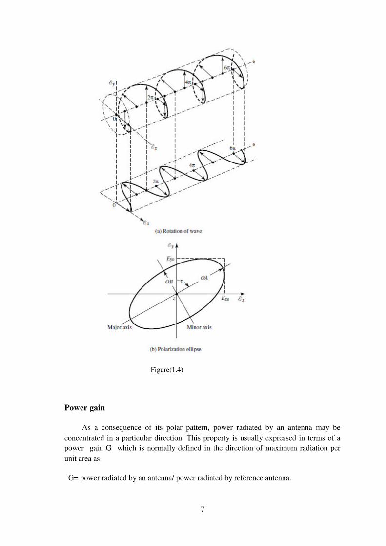
Polarization
An electromagnetic wave lunched from an antenna may be vertically or
horizontally polarized. In the former case, the E vector is vertical and require a vertical
antenna to lunch it. Alternatively, if the E vector is horizontal, the wave is horizontally
polarized and require a horizontal antenna to lunch it . Vertical or horizontal
polarization is also called linear polarization. Sometimes circular polarization is used,
which is a combination of vertical and horizontal polarization, Electromagnetic waves
are usually vertically polarized [12].
7
Figure(1.4)
Power gain
As a consequence of its polar pattern, power radiated by an antenna may be
concentrated in a particular direction. This property is usually expressed in terms of a
power gain G which is normally defined in the direction of maximum radiation per unit area as
G= power radiated by an antenna/ power radiated by reference antenna.
8
The power radiated by an antenna is slightly less than the input power because of losses
in the antenna. An alternative definition which assumes the antenna is lossless, is defined as the directive gain D given by
D= maximum power radiated per unit solid angle/ average power radiated per unit solid angle
With G=KD where K<1 and so G is slightly less than D. In practice, the power gain G
is commonly used and is expressed as a pure number or in dB by
Power gain = 10 log10 G dB [12].
Radiation resistance
The radiation resistance is associated with the power radiated by the antenna .if I is
the r.m.s (root mean square). antenna current and Rr ( radiation resistance) , then the
power radiated is I2Rr watts where Rr (fictitious resistance), which accounts for the
radiated power somewhat like a circuit resistance which dissipates heat . The radiation
resistance should be large, as the greater Rr is the greater the power radiated by the
antenna.
In contrast, for a receiving antenna, its terminal impedance is important. The terminal
impedance is defined as the ratio of voltage to current at its terminals and generally it
must be matched to the connecting line or cable. The terminal impedance of an antenna may or may not equal its radiation resistance, though in some cases, they are equal[12].
Effective aperture
The power received by an antenna can be associated with a collecting area . Every
antenna may be considered to have such a collecting area which is called its effective
aperture Ae. If Pd is the power density at the antenna and PR is the received power
available at the antenna terminals, then
PR = Pd A e watts
Ae= PR/Pd m2 OR
An antenna with power gain G has an effective aperture Ae at the operating wavelength
� which is given by ;
M2 Ae= G �2/4
The effective aperture Ae may be associated with a physical aperture as in the case of a
microwave horn, though it is usually less than the physical aperture. However, even a

9
linear antenna such as a dipole, can be associated with an effective aperture even though it has no physical aperture [12].
Band width
Wide bandwidth are required to meet growing traffic demands and in military
applications, where there is a need for frequency agility. In addition, higher operating
frequencies tend to be employed, as many antenna structures and waveguide
components are more convenient to use at higher frequencies. However, the use of
frequencies around 40GHz or more, produce other problems associated with component fabrication, higher attenuation and the generation of high power [12].
Return loss
is the loss of signal power resulting from the reflection caused at a discontinuity
in a transmission line or optical fiber. This discontinuity can be a mismatch with the
terminating load or with a device inserted in the line. It is usually expressed as a ratio in
decibels (dB);
r
i
p
pdBRl10
log10)( =
where RL(dB) is the return loss in dB, Pi is the incident power and Pr is the reflected
power.
Return loss is related to both standing wave ratio (SWR) and reflection
coefficient (�). Increasing return loss corresponds to lower SWR. Return loss is a
measure of how well devices or lines are matched. A match is good if the return loss is high. A high return loss is desirable and results in a lower insertion loss.
Return loss is used in modern practice in preference to SWR because it has better
resolution for small values of reflected wave[14].
Power transfer
For the maximum transfer of power from a receiving antenna to a receiver , the
impedance of the antenna should be matched to the input impedance of the receiver, in
accordance with the maximum power transfer theorem .As the antenna impedance is
normally resistive, this means that the input impedance of the receiver should also be
resistive. If Vis the induced r.m.s. voltage in an antenna connected to a receiver with an
input resistance Ri, it is shown in appendix B, that the maximum power received is given by PR(max)= V2 /4Ri watts[12].
10
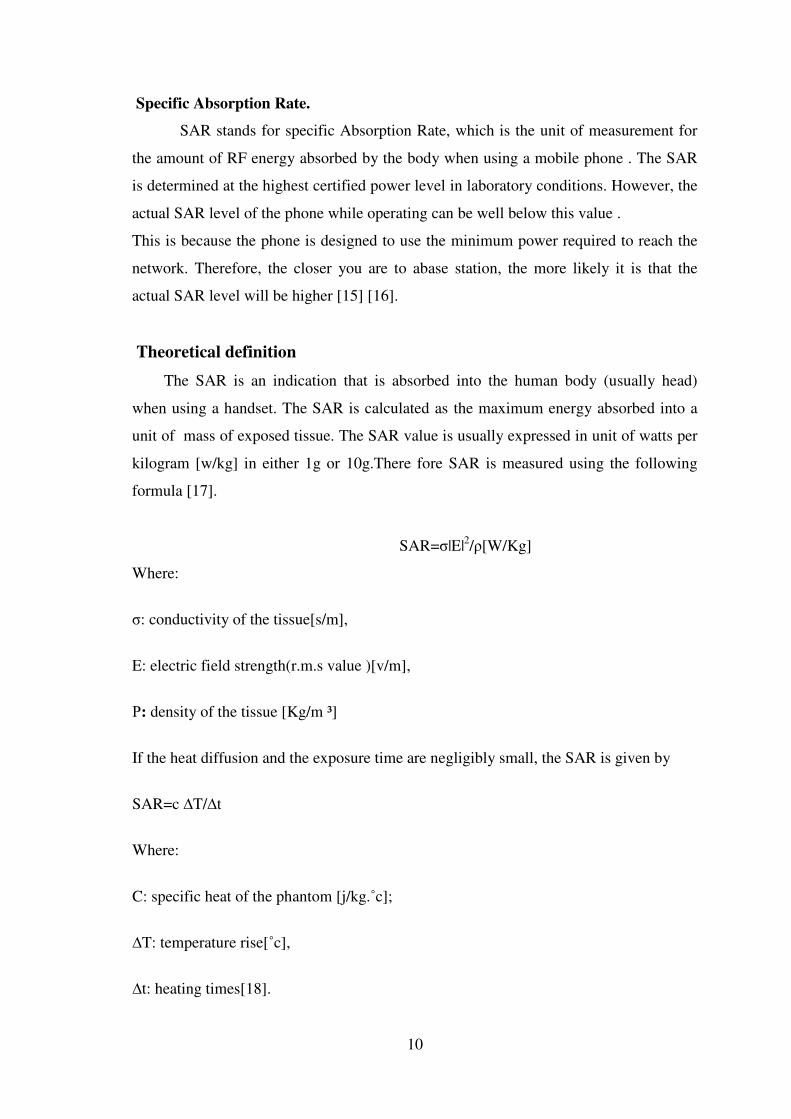
Specific Absorption Rate.
SAR stands for specific Absorption Rate, which is the unit of measurement for
the amount of RF energy absorbed by the body when using a mobile phone . The SAR
is determined at the highest certified power level in laboratory conditions. However, the
actual SAR level of the phone while operating can be well below this value .
This is because the phone is designed to use the minimum power required to reach the
network. Therefore, the closer you are to abase station, the more likely it is that the
actual SAR level will be higher [15] [16].
Theoretical definition
The SAR is an indication that is absorbed into the human body (usually head)
when using a handset. The SAR is calculated as the maximum energy absorbed into a
unit of mass of exposed tissue. The SAR value is usually expressed in unit of watts per
kilogram [w/kg] in either 1g or 10g.There fore SAR is measured using the following
formula [17].
SAR=�|E|2/�[W/Kg]
Where:
�: conductivity of the tissue[s/m],
E: electric field strength(r.m.s value )[v/m],
�: density of the tissue [Kg/m ³]
If the heat diffusion and the exposure time are negligibly small, the SAR is given by
SAR=c �T/�t
Where:
C: specific heat of the phantom [j/kg.˚c];
�T: temperature rise[˚c],
�t: heating times[18].
11
Near and Far fields
Not all the energy in the electromagnetic field around the antenna is radiated. Part
of the energy called the reactive energy is stored in the field and is recovered and
reemitted during successive oscillation. The region where we find reactive energy is
called the near field . in the near field, the electric and magnetic field component are not
perpendicular to each other. True near field exists only close to the radiator ,and it
extends for distance less than one wave length of the radiator.
In the far field, the electric and magnetic field are perpendicular to each other ,
thus making meaningful measurements of power density . The distance to the start of
the far field region from the radiator depends on the size of the antenna and on the wave
length of the radiation[19].
Between the end of the near field and the far field is the intermediate region (The
Fresnel region) a transition between two regions.
1.6 Types of Antennas
There are many types of microwave antennas, monopole antenna, dipole antenna
(the antenna used in mobile communications is dipole antenna ), helical antenna,
patched antenna. Electromagnetic radiation emerges in the direction in which the
aperture is facing . The microwave feed is mounted at the focus of the parabolic
reflector. The radiation is then reflected in a parallel beam. However , the beam does
spread with the amount of spread being inversely , proportional to the size of the
reflector . The measure of beam spread is called the beam width. The beam width is
defined as the width of the beam at the half power points and is measured in
degrees[20].
1.6.1 Directional Antennas Directional antennas are designed for use on point-to-point links, or as client
antenna in point-to-multipoint applications. Usually, they have the narrowest possible
beam width and significantly higher gain than other antenna types.
Essential rule to be applied is the higher the gain, the lower the beam width.
Directional antennas are usually constructed in form of grid or parabolic dish
antennas[21].
The co-channel interference in a cellular mobile communication system can be
reduced by replacing the omni-directional antenna at the base-station with several
directional antennas. The use of a directional antenna limits the number co-channel
interferers seen by any receiver within the cell. This is true because each directional
antenna only radiates within a desired sector. This technique is called sectoring.
12
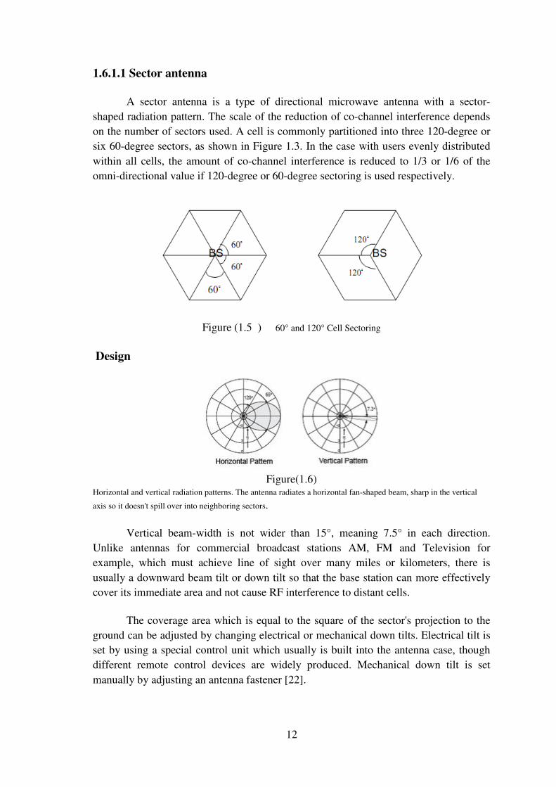
1.6.1.1 Sector antenna
A sector antenna is a type of directional microwave antenna with a sector-
shaped radiation pattern. The scale of the reduction of co-channel interference depends
on the number of sectors used. A cell is commonly partitioned into three 120-degree or
six 60-degree sectors, as shown in Figure 1.3. In the case with users evenly distributed
within all cells, the amount of co-channel interference is reduced to 1/3 or 1/6 of the
omni-directional value if 120-degree or 60-degree sectoring is used respectively.
Figure (1.5 ) 60° and 120° Cell Sectoring
Design
Figure(1.6)
Horizontal and vertical radiation patterns. The antenna radiates a horizontal fan-shaped beam, sharp in the vertical
axis so it doesn't spill over into neighboring sectors.
Vertical beam-width is not wider than 15°, meaning 7.5° in each direction.
Unlike antennas for commercial broadcast stations AM, FM and Television for
example, which must achieve line of sight over many miles or kilometers, there is
usually a downward beam tilt or down tilt so that the base station can more effectively cover its immediate area and not cause RF interference to distant cells.
The coverage area which is equal to the square of the sector's projection to the
ground can be adjusted by changing electrical or mechanical down tilts. Electrical tilt is
set by using a special control unit which usually is built into the antenna case, though
different remote control devices are widely produced. Mechanical down tilt is set
manually by adjusting an antenna fastener [22].
13
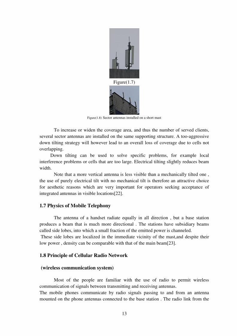
Figure(1.7)
Figure(1.8) Sector antennas installed on a short mast
To increase or widen the coverage area, and thus the number of served clients,
several sector antennas are installed on the same supporting structure. A too-aggressive
down tilting strategy will however lead to an overall loss of coverage due to cells not
overlapping.
Down tilting can be used to solve specific problems, for example local
interference problems or cells that are too large. Electrical tilting slightly reduces beam
width.
Note that a more vertical antenna is less visible than a mechanically tilted one ,
the use of purely electrical tilt with no mechanical tilt is therefore an attractive choice
for aesthetic reasons which are very important for operators seeking acceptance of
integrated antennas in visible locations[22].
1.7 Physics of Mobile Telephony
The antenna of a handset radiate equally in all direction , but a base station
produces a beam that is much more directional . The stations have subsidiary beams
called side lobes, into which a small fraction of the emitted power is channeled.
These side lobes are localized in the immediate vicinity of the mast,and despite their
low power , density can be comparable with that of the main beam[23].
1.8 Principle of Cellular Radio Network
(wireless communication system)
Most of the people are familiar with the use of radio to permit wireless
communication of signals between transmitting and receiving antennas.
The mobile phones communicate by radio signals passing to and from an antenna
mounted on the phone antennas connected to the base station . The radio link from the
14
phone to the base station is known as the uplink and carries the speech from the mobile
phone user . A separate radio link from the base station to the phone is known as the
down link and this carries the speech from the person to whom the phone user is
listening.
Transmitted signal strength falls off rapidly with distance from base station and
mobile phones, but a certain minimum signal strength is required for adequate
reception. This means that a large number of base station is needed to provide coverage
of the whole area.
The power radiated by base station has to be carefully controlled in any
frequency reuse scheme to limit the distance traveled by signals . operators tend to
divide the area around a base station into three sectors and then mount three different
sets of antennas of the mast such that each set provides coverage of 120 �[23].
1.9 General Effect of Radio Frequency Radiation (base station)
First of all, it must be stated that biological effects of the field parameters of
cellular phone base stations depend to large extent on the location of emitting source
and exposed objects, presence of reflecting article and grounding in the neighborhood
[24].
As regards exposure to cell mast radiation, chronic exposure becomes an important
factor which may cause serious effects. Intensity and exposure radiation do interact to
produce an effect[25].
It found that with extremely low frequency magnetic field that "lower intensity,
longer duration exposure can produce the same effect as from "a higher intensity,
shorter duration exposure ". Thus, the interaction of exposure parameters , the duration
of exposure , whether the effect is cumulative, involvement of compensatory response,
and the time of breakdown of homeostasis after long term exposure , play important
roles in determining the possible health consequence of exposure to radiation emitted by
cell masts [25]
15
CAPTER TWO
Brief Review of Interaction of EM Waves with Biological Tissue.
2.1 Introduction:
Today the effect of mobile phone radiation on human health become the subject
of recent interest and study, as a result of the enormous increase in mobile phone usage in the world. Mobile phone use electromagnetic radiation in the microwave range .
Many scientific studies have investigated possible health symptoms of mobile
phone radiation. These studies are occasionally reviewed by some scientific committees
to assess overall risks. A recent assessment was published in 2007 by the European
Commission Scientific Committee on Emerging and Newly Identified Health Risks (SCENIHR)[26].
It concludes that the three lines of evidence, viz. animal, in vitro, and
epidemiological studies, indicate that exposure to RF fields is unlikely to lead to an increase in cancer in humans.
This chapter represents an important turn in the project. It focuses on the biological
effect resulting from the wireless services; particularly the GSM 900MHz.
It examine the human body structure, absorption rate the active cell, and the
natural-safe absorption rate for humans based on the principles and measurements of
the World Health Organization.
The available literature and previous studies conducted on the topic show the
effect resulting from the use of cell phones on human’s head depending on the
biological structure of brain’s cells. These studies also examine the thermal effect on the
brain’s cell in which changes on the structure of the DNA have been documented.
Another study shows the effect of frequencies resulting from the transmission
stations on sleeping habits and the accompanied consequences. Other studies show
plain evidence of the effects of the wireless services in causing cancer.

16
2.2 human body structure
a- Cell : The cell is the structural and the functional unit with which the human body is built.
b- Tissue :Tissues are materials made up of groups of similar cells. Cells are of various
types, and tissues vary according to the types of cells in their structure. There are four main types of tissue in the human body:
c- Organs and Systems
Tissues are jointed into larger units called organs, such as the heart, lungs, brain,
liver. Each organ is made up of types of tissue, which enable it to do its special work.
A system is a group of organs, which together carry out one of the essential
functions of the body. There are nine systems. All of these systems work harmoniously
together in a healthy body[27].
2.2.1 Skin tissue
skin is an organ of the integumentary system made up of a layer of tissues that
guard underlying muscles and organs. As the interface with the surroundings, it plays
the most important role in protecting against pathogens. Its other main functions are
insulation and temperature regulation.
Skin is composed of the epidermis and the dermis. Below these layers lies the
hypodermis (subcutaneous adipose layer), which is not usually classified as a layer of
skin [28].
2.2.2 Bones
Are rigid organs that constitute part of the endoskeleton of vertebrates. They
support, and protect the various organs of the body, produce red and white blood cells
and store minerals. Bone tissue is a type of dense connective tissue. Bones come in a
variety of shapes and have a complex internal and external structure, are lightweight yet
strong and hard, and serve multiple functions. One of the types of tissue that makes up
bone is the mineralized osseous tissue, also called bone tissue, that gives it rigidity and a
honeycomb-like three-dimensional internal structure. Other types of tissue found in
bones include marrow, endosteum and periosteum, nerves, blood vessels and cartilage.
At birth, there are over 270 bones in an infant human's body, but many of these fuse
together as the child grows, leaving a total of 206 separate bones in an adult. The largest bone in the human body is the femur and the smallest bones are auditory ossicles.
The primary tissue of bone, osseous tissue, is a relatively hard and lightweight
composite material, formed mostly of calcium phosphate in the chemical arrangement
termed calcium hydroxyl apatite (thesis the osseous tissue that gives bones their
rigidity). It has relatively high compressive strength, of about 170 MPa (1800 kgf/cm²)
but poor tensile strength of 104–121 MPa and very low shear stress strength (51.6
17
MPa), meaning it resists pushing forces well, but not pulling or torsional forces. While
bone is essentially brittle, it does have a significant degree of elasticity, contributed
chiefly by collagen. All bones consist of living and dead cells embedded in the
mineralized organic matrix that makes up the osseous tissue.
2.2.2.1 Bone structure
Compact (cortical) bone
The hard outer layer of bones is composed of compact bone tissue, so-called due
to its minimal gaps and spaces. Its porosity is 5–30%. This tissue gives bones their
smooth, white, and solid appearance, and accounts for 80% of the total bone mass of an adult skeleton. Compact bone may also be referred to as dense bone.
Trabecular (cancellous) bone
Filling the interior of the bone is the trabecular bone tissue (an open cell porous
network also called cancellous or spongy bone), which is composed of a network of
rod- and plate-like elements that make the overall organ lighter and allow room for
blood vessels and marrow. Trabecular bone accounts for the remaining 20% of total
bone mass but has nearly ten times the surface area of compact bone. Its porosity is 30–
90%. If, for any reason, there is an alteration in the strain the cancellous is subjected to,
there is a rearrangement of the trabeculae. The microscopic difference between compact
and cancellous bone is that compact bone consists of haversian sites and osteons, while
cancellous bones do not. Also, bone surrounds blood in the compact bone, while blood surrounds bone in the cancellous bone[29].
2.2.2.2 Skull
The human skull, scientifically known as the cranium, consists of 22 bones. The
skull can be broken into two regions, the cranial section and the facial section. The
cranial bones consist of the bones in the top of the skull while the facial bones consist of
the bones that make up your face. The skulls primary functions are protection of the
brain and support of the face. In the skull, sinal cavities can be found. Although the
function of these cavities is still not definitively known, it may be that the sinuses
function are to decreasing the weight of the skull while maintaining strength[30].
2.2.3 Brain
The brain is the center of the nervous system in all vertebrate and most
invertebrate animals—only a few primitive invertebrates such as sponges, jellyfish,
adult sea squirts and starfishes do not have one. It is located in the head, usually close to
the primary sensory organs for such senses as vision, hearing, balance, taste, and smell.
The brain of a vertebrate is the most complex organ in its body. In a typical human the
cerebral cortex (the largest part) is estimated to contain 15–33 billion neurons[31] each
connected by synapses to several thousand other neurons. These neurons communicate
18
with one another by means of long protoplasmic fibers called axons, which carry trains
of signal pulses called action potentials to distant parts of the brain or body targeting
specific recipient cells.
From an evolutionary-biological point of view, the function of the brain is to
exert centralized control over the other organs of the body. The brain acts on the rest of
the body either by generating patterns of muscle activity or by driving secretion of
chemicals called hormones. This centralized control allows rapid and coordinated
responses to changes in the environment. Some basic types of responsiveness such as
reflexes can be mediated by the spinal cord or peripheral ganglia, but sophisticated
purposeful control of behavior based on complex sensory input requires the information-integrating capabilities of a centralized brain.
From a philosophical point of view, what makes the brain special in comparison
to other organs is that it forms the physical structure that generates the mind. As
Hippocrates put it: "Men ought to know that from nothing else but the brain come joys,
delights, laughter and sports, and sorrows, griefs, despondency, and lamentations" [32].
In the early part of psychology, the mind was thought to be separate from the
brain. However, after early scientists conducted experiments it was determined that the
mind was a component of a functioning brain that expressed certain behaviours based on the external environment and the development of the organism[33].
The mechanisms by which brain activity gives rise to consciousness and
thought have been very challenging to understand: despite rapid scientific progress,
much about how the brain works remains a mystery. The operations of individual brain
cells are now understood in considerable detail, but the way they cooperate in
ensembles of millions has been very difficult to decipher. The most promising
approaches treat the brain as a biological computer, very different in mechanism from
electronic computers, but similar in the sense that it acquires information from the
surrounding world, stores it, and processes it in a variety of ways.
2.3 Radiation absorption:
Part of the radio waves emitted by a mobile telephone handset are absorbed by the
human head. Digital mobile technologies, such as CDMA2000 and D-AMPS, use lower
output power, typically below 1 watt. The maximum power output from a mobile phone
is regulated by the mobile phone standard and by the regulatory agencies in each
country. In most systems the cell phone and the base station check reception quality and
signal strength and the power level is increased or decreased automatically, within a
certain span, to accommodate different situations, such as inside or outside of buildings
and vehicles. The rate at which radiation is absorbed by the human body is measured by
the Specific Absorption Rate (SAR), and its maximum levels for modern handsets have
been set by governmental regulating agencies in many countries. SAR values are
19
heavily dependent on the size of the averaging volume. Without information about the
averaging volume used, comparisons between different measurements cannot be made[34].
It is worth noting that thermal radiation is not comparable to ionizing radiation in
that it only increases the temperature in normal matter, it does not break molecular
bonds or release electrons from their atoms.
2.4 Rate of absorption of the human head to radiation
The mobile phone system is referred to as “cellular telephone system” because
the coverage area is divided into “cells “each of which has a base station antenna.
Mobile phone technology uses electromagnetic radiation in the Giga hertz range.
These radiations are close to microwave range and with similar properties. Part of the
radio wave emitted from the mobile phone is absorbed by the human head. The radiation emitted by a GSM handset can have a peak power of 2 watts[35].
Figure(2.1)
If the SAR level is above the limit, it may cause both thermal and non thermal
effects on the body especially on the ear and head since these are at the “Near Field” of
the radiation. Thermal effect of microwave is the dielectric heating in which any
dielectric material such as living tissue is heated by rotations of polar molecules such as water [36].
20
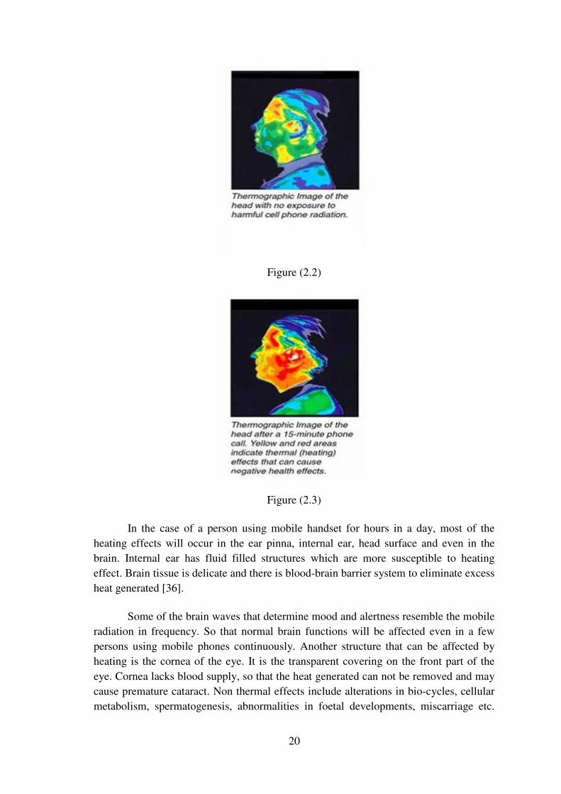
Figure (2.2)
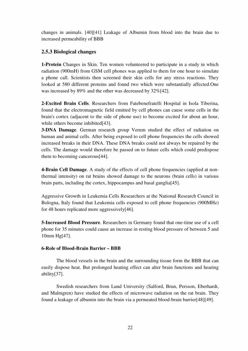
Figure (2.3)
In the case of a person using mobile handset for hours in a day, most of the
heating effects will occur in the ear pinna, internal ear, head surface and even in the
brain. Internal ear has fluid filled structures which are more susceptible to heating
effect. Brain tissue is delicate and there is blood-brain barrier system to eliminate excess
heat generated [36].
Some of the brain waves that determine mood and alertness resemble the mobile
radiation in frequency. So that normal brain functions will be affected even in a few
persons using mobile phones continuously. Another structure that can be affected by
heating is the cornea of the eye. It is the transparent covering on the front part of the
eye. Cornea lacks blood supply, so that the heat generated can not be removed and may
cause premature cataract. Non thermal effects include alterations in bio-cycles, cellular
metabolism, spermatogenesis, abnormalities in foetal developments, miscarriage etc.

21
Some users of mobile phones feel several unspecific symptoms during and after the use
of mobile phones in the form of burning and tingling sensations, fatigue, sleep
disturbances, dizziness, loss of mental concentration etc. All these may be due to the
influence of the radiation on the bio magnetic field of the body [37].
2.5 Biological effects of Mobile phone radiation
2.5.1 Thermal Effect
Microwave causes dielectric heating in the human body. Human tissue is rich in
water and exhibit dielectric property (+ and – ve ions).
Living tissue heat up through the rotation of polar molecules such as water. This
friction causes heating of tissue .Head is in the “near field “ of radiation, so that most of
the heating effect occurs in the head. Temperature in the internal ear, brain etc increases
to 1 degree or more. This adversely affects the functioning of these organs since these have fluid filled cavities. In short Thermal effect causes
• Burning sensation in the Scalp and Ear pinna
• Mood alteration and lack of concentration
• Lethargy and lack of sleep
• Whistling sound in the ear
• Premature Cataract- the cornea of the eye does not have this temperature
regulation mechanism and exposure of 2–3 hours duration has been reported to
produce cataracts in rabbits' eyes at SAR values from 100-140W/kg, which
produced lenticular temperatures of 41°C. There were no cataracts detected in
the eyes of monkeys exposed under similar conditions [38].
• Confusion and loss of memory since the microwaves interfere with the mood
controlling brainwaves
• Alters sleep physiology and biological rhythm by changing the level of Dopamine, Serotonin hormones
2.5.2 Non Thermal Effects Non-thermal
In most countries the mobile radiation safety standards are based on the
assumption that the only biological effect of microwave (mobile phone) radiation is
heating (the so called "thermal effect"). However ample evidence demonstrate that non-
thermal effects do exist and may occur at a significantly lower radiation level than what
causes heating. This means that present safety standards need to be changed so that they allow considerably lower levels of radiation intensities [39].
Increased cellular responses, Cellular changes demonstrated at non-thermal
levels. A Finnish team has found that certain proteins in human cells change due to the
radiation at non-thermal intensity levels. This confirms earlier findings of cellular
22
changes in animals. [40][41] Leakage of Albumin from blood into the brain due to increased permeability of BBB
2.5.3 Biological changes
1-Protein Changes in Skin. Ten women volunteered to participate in a study in which
radiation (900mH) from GSM cell phones was applied to them for one hour to simulate
a phone call. Scientists then screened their skin cells for any stress reactions. They
looked at 580 different proteins and found two which were substantially affected.One was increased by 89% and the other was decreased by 32%[42].
2-Excited Brain Cells. Researchers from Fatebenefratelli Hospital in Isola Tiberina,
found that the electromagnetic field emitted by cell phones can cause some cells in the
brain's cortex (adjacent to the side of phone use) to become excited for about an hour,
while others become inhibited[43].
3-DNA Damage. German research group Verum studied the effect of radiation on
human and animal cells. After being exposed to cell phone frequencies the cells showed
increased breaks in their DNA. These DNA breaks could not always be repaired by the
cells. The damage would therefore be passed on to future cells which could predispose
them to becoming cancerous[44].
4-Brain Cell Damage. A study of the effects of cell phone frequencies (applied at non-
thermal intensity) on rat brains showed damage to the neurons (brain cells) in various
brain parts, including the cortex, hippocampus and basal ganglia[45].
Aggressive Growth in Leukemia Cells Researchers at the National Research Council in
Bologna, Italy found that Leukemia cells exposed to cell phone frequencies (900MHz)
for 48 hours replicated more aggressively[46].
5-Increased Blood Pressure. Researchers in Germany found that one-time use of a cell
phone for 35 minutes could cause an increase in resting blood pressure of between 5 and
10mm Hg[47].
6-Role of Blood-Brain Barrier – BBB
The blood vessels in the brain and the surrounding tissue form the BBB that can
easily dispose heat. But prolonged heating effect can alter brain functions and hearing ability[37].
Swedish researchers from Lund University (Salford, Brun, Persson, Eberhardt,
and Malmgren) have studied the effects of microwave radiation on the rat brain. They
found a leakage of albumin into the brain via a permeated blood-brain barrier[48][49].
23
7-Hearing impairments
• Heating effect in the fluid of internal ear
• Piercing sound from the speaker causes irritability in the ear drum and internal sensory cells of ear Human ear is highly sensitive to waves between 1000 and 6000 Hz[49].
8-Sleep and EEG Effects
Sleep, EEG and waking rCBF have been studied in relation to RF exposure for a
decade now, and the majority of papers published to date have found some form of
effect. While a Finnish study failed to find any effect on sleep or other cognitive
function from pulsed RF exposure,[50]. most other papers have found significant effects
on sleep[51]. Two of these papers found the effect was only present when the exposure
was pulsed (amplitude modulated), and one early paper actually found that sleep quality (measured by the amount of participants' broken sleep) actually improved.
While some papers were inconclusive or inconsistent,[52][53] a number of
studies have now demonstrated reversible EEG and rCBF alterations from exposure to
pulsed RF exposure[54]. German research from 2006 found that statistically significant
EEG changes could be consistently found, but only in a relatively low proportion of study participants (12 - 30%)[55].
Microwave Auditory Effect
• Clicks and Buzzing sound in the head
• Microwave induces electric current in the hearing centre of the brain and causes Auditory illusion
• This may happen if music is heard using ear phone or Bluetooth for long time
• The human ear has a peak sensitivity of 3000 Hz, which causes a sense of unease. Alarms and Mobile ring tones are designed to sound at 3000 Hz.
• The ear has a very low threshold of hearing for 3000 Hz. A sound of this frequency is very penetrating[56].
Phantom Pain
Pain in the ear without any specific reasons like infection.This may be due to
increased stress on the delicate structures of the internal ear or ear drum by the radiation[57].

24
Electromagnetic Hypersensitivity
Unspecific symptoms during and after the use of cell phone Tingling sensation,
fatigue, dizziness, loss of mental attention, reduction in reaction time, memory retentiveness, tachycardia etc[58].
All of these symptoms can also be attributed to stress and that current research cannot separate the symptoms from nocebo effects[59].
2.6 Cancer:
In 2006 a large Danish study about the connection between mobile phone use
and cancer incidence was published. It followed over 420,000 Danish citizens for 20
years and showed no increased risk of cancer[60]. The German Federal Office for
Radiation Protection (Bundesamt fur Strahlenschutz) considers this report inconclusive[61].
The following studies of long time exposure have been published:
The 13 nation INTERPHONE project – the largest study of its kind ever
undertaken – has now been published and did not find a solid link between mobile phones and brain tumours[62].
The International Journal of Epidemiology published[63] a combined data
analysis from a multi national population-based case-control study of glioma and meningioma, the most common types of brain tumour.
The authors reported the following conclusion:
Overall, no increase in risk of glioma or meningioma was observed with use of
mobile phones. There were suggestions of an increased risk of glioma at the highest
exposure levels, but biases and error prevent a causal interpretation. The possible effects of long-term heavy use of mobile phones require further investigation.
In the press release[64] accompanying the release of the paper, Dr Christopher Wild, Director of the International Agency for Research on Cancer (IARC) said:
An increased risk of brain cancer is not established from the data from Interphone.
However, observations at the highest level of cumulative call time and the changing
patterns of mobile phone use since the period studied by Interphone, particularly in
young people, mean that further investigation of mobile phone use and brain cancer risk is merited.
25
A number of independent health and government authorities have commented on
this important study including The Australian Centre for Radiofrequency Bio effects Research (ACRBR) which said in a statement that[65].
Until now there have been concerns that mobile phones were causing increases in
brain tumours. Interphone is both large and rigorous enough to address this claim, and it
has not provided any convincing scientific evidence of an association between mobile
phone use and the development of glioma or meningioma. While the study demonstrates
some weak evidence of an association with the highest tenth of cumulative call time
(but only in those who started mobile phone use most recently), the authors conclude
that biases and errors limit the strength of any conclusions in this group. It now seems
clear that if there was an effect of mobile phone use on brain tumour risks in adults, this
is likely to be too small to be detectable by even a large multinational study of the size of Interphone
This concludes that currently available data do not warrant any general ecommendation
to limit use of mobile phones in the adult population,
Chief Executive Officer, Professor Ian Olver, said findings from the Interphone study,
conducted across 13 countries including Australia, were consistent with other research that had failed to find a link between mobile phones and cancer.
This supports previous research showing mobile phones don’t damage cell DNA,
meaning they can’t cause the type of genetic mutations that develop into cancer,” Professor Olver said.
However, it has been suggested that electromagnetic fields associated with mobile
phones may play a role in speeding up the development of an existing cancer. The
Interphone study found no evidence to support this theory.
• A Danish study (2004) that took place over 10 years found no evidence to
support a link. However, this study has been criticized for collecting data from
subscriptions and not necessarily from actual users. It is known that some
subscribers do not use the phones themselves but provide them for family
members to use. That this happens is supported by the observation that only
61% of a small sample of the subscribers reported use of mobile phones when responding to a questionnaire[66][67].
• A Swedish study (2005) that draws the conclusion that "the data do not support
the hypothesis that mobile phone use is related to an increased risk of glioma or
meningioma."[68].
• A German study (2006) that states "In conclusion, no overall increased risk of
glioma or meningioma was observed among these cellular phone users;
however, for long-term cellular phone users, results need to be confirmed before firm conclusions can be drawn."[69].
26
Other studies on cancer and mobile phones are:
• A Swedish scientific team at the Karolinska Institute conducted an
epidemiological study (2004) that suggested that regular use of a mobile phone
over a decade or more was associated with an increased risk of acoustic
neuroma, a type of benign brain tumor. The increase was not noted in those who
had used phones for fewer than 10 years[70].
• The INTERPHONE study group from Japan published the results of a study of
brain tumour risk and mobile phone use. They used a new approach:
determining the SAR inside a tumour by calculating the radio frequency field
absorption in the exact tumour location. Cases examined included glioma,
meningioma, and pituitary adenoma. They reported that the overall odds ratio
(OR) was not increased and that there was no significant trend towards an increasing OR in relation to exposure, as measured by SAR[70].
In 2007, Dr. Lennart Hardell, from Örebro University in Sweden, reviewed published
epidemiological papers (2 cohort studies and 16 case-control studies) and found that[70]:
• Cell phone users had an increased risk of malignant gliomas.
• Link between cell phone use and a higher rate of acoustic neuromas.
• Tumors are more likely to occur on the side of the head that the cell handset is used.
One hour of cell phone use per day significantly increases tumor risk after ten
years or more On 31 May 2011 the International Agency for Research on Cancer
classified radiofrequency electromagnetic fields as possibly carcinogenic to humans
(Group 2B). The IARC assessed and evaluated available literature and studies about the
carcinogenicity of radiofrequency electromagnetic fields (RF-EMF), and found the
evidence to be "limited for carcinogenicity of RF-EMF, based on positive associations
between glioma and acoustic neuroma and exposure". The conclusion of the IARC was
mainly based on the INTERPHONE study, which found an increased risk for glioma in
the highest category of heavy users (30 minutes per day over a 10 year period),
although no increased risk was found at lower exposure and other studies could not
back up the findings. The evidence for other types of cancer was found to be
"inadequate". Some members of the Working Group opposed the conclusions and
considered the current evidence in humans still as “inadequate”, citing inconsistencies between the assessed studies[71].
Researchers at the National Cancer Institute found that while cell phone use
increased substantially over the period 1992 to 2008 (from nearly zero to almost 100
percent of the population), the U.S. trends in glioma incidence did not mirror that
increase[72].
27
2.7 Conclusion
we found that the electromagnetic radiation that emitted from mobile phone
have an affect on human head and human body in general so we must reduce this affect
to protect the population living around base stations and users of mobile handsets,
governments and regulatory bodies adopt safety standards, which translate to limits on
exposure levels below a certain value. There are many proposed national and
international standards, but that of the International Commission for Non-Ionizing
Radiation Protection (ICNIRP) is the most respected one, and has been adopted so far
by more than 80 countries. For radio stations, ICNIRP proposes two safety levels: one
for occupational exposure, another one for the general population. Currently there are efforts underway to harmonise the different standards in existence[72].
Here are some recommendations based on all available evidence especially
regarding brain tumors:
1. Limit the use of cell phones ...keep calls short.
2. Children should (not) be allowed to use a cell phone (other than)in..emergency... Because of their .. (thin) skulls, the radiation can penetrate much more deeply.
3. Wear an air tube headset (not regular wired headset). The regular wired headset has
been found to intensify radiation into the ear canal. The wire not only transmits the
radiation from the cell phone but also serves as an antenna, attracting EMFs from the
surroundings.
4. Do not put the cell phone in a pocket or a belt while in use or while it is on. The body
tissue in the lower body area has good conductivity and absorbs radiation more quickly
than the head. One study shows that men who wear cell phones near their groin could have their sperm count dropped by as much as 30%.
5. If (no) headset, wait for the call to connect before placing the phone next to the ear.
6. Do not use the cell phone in enclosed metal spaces such as vehicles or elevators, where devices may use more power to establish connection.
7. Do not make a call when the signal strength is (weak) (1 bar or less), (because much
stronger radiation is then emitted by the phone).
8. Purchase a phone with a low SAR. Most phones have a SAR level listed in its
instruction manual. The SAR level is a way of measuring the quantity of RF energy that is absorbed by the body.
9. Use text instead of talk.
28
10. Use landlines.
11. Keep cell phone off most of the time. Let people leave messages and then call them back from a landline.
12. Limit the use of cell phones in rural areas (because the signal is mostly weak there prompting strong radiation from the cell phone)[73].
29
CHAPTER THREE
Maxwell’s Equations and Finite Difference Time Domain (FDTD)
Introduction:
The physics and the distribution of the electromagnetic waves of the Finite
difference Time Domain (FDTD) along with the functionality and the general math
formula has been discussed. It incorporates the Maxwell equation used to control
(FDTD).
Additionally, it examines of specific absorption rate of the active cell SAR and
formulating the general mathematical equation of the absorption rate to identify the
stimulate propagation in media that have conductivity.
To meet the main goal of the study, human head is approached in this study by
examining the effect of the antenna on the skin, the bone, and the brain.
3.1 Finite-Difference Time-Domain (FDTD)
3.1.1 Finite-Difference Time-Domain (FDTD)
FDTD is one of the primary available computational electrodynamics modeling
techniques. Since it is a time-domain method, FDTD solutions can cover a wide
frequency range with a single simulation run, and treat nonlinear material properties in a
natural way.
The FDTD method belongs in the general class of grid-based differential time-
domain numerical modeling methods. The time-dependent Maxwell's equations (in
partial differential form) are discretized using central-difference approximations to the
space and time partial derivatives. The resulting finite-difference equations are solved in
either software or hardware in a leapfrog manner: the electric field vector components
in a volume of space are solved at a given instant in time; then the magnetic field vector
components in the same spatial volume are solved at the next instant in time; and the
process is repeated over and over again until the desired transient or steady-state
electromagnetic field behavior is fully evolved.
The basic FDTD space grid and time-stepping algorithm trace back to a seminal
1966 paper by Kane Yee in IEEE Transactions on Antennas and Propagation.[74].
30
The descriptor "Finite-difference time-domain" and its corresponding "FDTD"
acronym were originated by Allen Taflove in a 1980 paper in IEEE Transactions on
Electromagnetic Compatibility[75].
3.1.2 Using the FDTD method
To implement an FDTD solution of Maxwell's equations, a computational
domain must first be established. The computational domain is simply the physical
region over which the simulation will be performed. The E and H fields are determined
at every point in space within that computational domain. The material of each cell
within the computational domain must be specified. Typically, the material is either
free-space (air), metal, or dielectric. Any material can be used as long as the
permeability, permittivity, and conductivity are specified.
Once the computational domain and the grid materials are established, a source is
specified. The source can be an impinging plane wave, a current on a wire, or an applied
electric field, depending on the application.
Since the E and H fields are determined directly, the output of the simulation is
usually the E or H field at a point or a series of points within the computational domain.
The simulation evolves the E and H fields forward in time.
Processing may be done on the E and H fields returned by the simulation. Data
processing may also occur while the simulation is ongoing. While the FDTD technique
computes electromagnetic fields within a compact spatial region, scattered and/or
radiated far fields can be obtained via near-to-far-field transformation[76].
3.1.3 Workings of the FDTD method
When Maxwell's differential equations are examined, it can be seen that the change
in the E-field in time (the time derivative) is dependent on the change in the H-field
across space (the curl). This results in the basic FDTD time-stepping relation that, at
any point in space, the updated value of the E-field in time is dependent on the stored
value of the E-field and the numerical curl of the local distribution of the H-field in
space[77].
The H-field is time-stepped in a similar manner. At any point in space, the
updated value of the H-field in time is dependent on the stored value of the H-field and
the numerical curl of the local distribution of the E-field in space. Iterating the E-field
and H-field updates results in a marching-in-time process where in sampled-data
31
analogs of the continuous electromagnetic waves under consideration propagate in a
numerical grid stored in the computer memory.
Figure (3.1)
Illustration of a standard Cartesian Yee cell used for FDTD, about which electric and magnetic field vector
components are distributed.
Visualized as a cubic voxel, the electric field components form the edges of the
cube, and the magnetic field components form the normals to the faces of the cube. A
three-dimensional space lattice consists of a multiplicity of such Yee cells. An
electromagnetic wave interaction structure is mapped into the space lattice by assigning
appropriate values of permittivity to each electric field component, and permeability to
each magnetic field component.
This description holds true for 1-D, 2-D, and 3-D FDTD techniques. When
multiple dimensions are considered, calculating the numerical curl can become
complicated. Kane Yee's seminal 1966 paper proposed spatially staggering the vector
components of the E-field and H-field about rectangular unit cells of a Cartesian
computational grid so that each E-field vector component is located midway between a
pair of H-field vector components, and conversely[78][79].
On the plus side, this explicit time-stepping scheme avoids the need to solve
simultaneous equations, and furthermore yields dissipation-free numerical wave
propagation. On the minus side, this scheme mandates an upper bound on the time-step
to ensure numerical stability[80].
As a result, certain classes of simulations can require many thousands of time-steps
for completion.
32
3.1.4 FDTD formulation
In the FDTD approach, both the space and time are divided into discrete
segments. Space is segmented into box-shaped cells, which are small in
comparison to the wavelength. The electric fields (Ex(i,j,k), Ey(i,j,k) and Ez(i,j,k))
are located on the edges of the box, and the magnetic fields (Hx(i,j,k), Hy(i,j,k)
and Hz(i,j,k)) are positioned on the faces as shown in Figure 1.
This orientation of the fields is known as the Yee cell [14] and is the basis for
FDTD The time is divided into small lapses where each step represents the time
required for the field to travel from one cell to the next. Given an offset in space of
the magnetic fields in relation to the electric fields, the values of the field in respect to
time are also offset.
The electric and magnetic fields are updated using a leapfrog scheme where
the electric fields come first, then the magnetic ones are computed at each step in time.
When many FDTD cells are combined together to form a three- dimensional
volume the result is an FDTD grid or mesh. Each FDTD cell will overlap the edges
and faces with their neighbours. Therefore each cell will have three electric fields
that begin at a common node associated with it. The electric fields at the other nine
edges of the FDTD cell will belong to other adjacent cells. .Each cell will also have
three magnetic fields originating on the faces of the cell adjacent to the common node
of the electric fields .
3.2.1 Maxwell’s equations
James Clark Maxwell published the famous Maxwell’s equations, which
mathematically describe the interdependence of the electric field and the magnetic field.
Maxwell suggested the existence of electromagnetic waves, which were discovered later
by other scientists. Differential form of time-dependent Maxwell’s equations:
( 3 . 1 )
( 3 . 2 )
0 ( 3 . 3 )
( 3 . 4 )..
BE
t
DH J
t
B
D ρ
∂∇ × = −
∂
∂∇ × = +
∂
∇ =
∇ =
� ��� ��
� ��� �� ��
� ��
� ���
where E is electric field intensity ,H is magnetic field intensity D is electric flux density
, B is magnetic flux density , J is electric current density

33
The time derivatives can be greatly simplified with the phasor forms as:
22
2
22
2
( 3 . 5 )
( 3 . 6 )
( 3 . 7 )
( 3 . 8 )
Ej E
t
EE
t
Hj H
t
HH
t
ω
ω
ω
ω
∂=
∂
∂= −
∂
∂=
∂
∂= −
∂
� ��� ��
� ��� ��
� ��� ��
� ��� ��
3.2.2 Theory and model Mathematical analysis of microwave heating equations in one dimensional skin-
layer has been discussed. the effect of microwave heating equations on the thermal
states of biological tissues and to predict the effects of the thermal physical properties
on the transient temperature of tissues and damage function. This research can be very
beneficial in widening the idea of clinical thermal technology and thermal medical
practices[13]. analytical formulations in SAR distribution calculations are extremely
difficult Computation of specific absorption rate in the human body to base-station
antennas using a Hybrid Formulation is found in reference [81]. SAR simulation in
wireless communication and safety discussions in the society discussed by M. O.
Ozyalcin [82]. A Multi-layered structure representing simplified model of the human
head irradiated by plane wave in the frequency range of 100MHz-300GHz was
investigated [83], general electromagnetic formulation on the absorption properties of
the layered head model is given exact analytical expressions are given for the plane
wave complex reflection coefficient as a function of frequency at the interference of the
stratified structure, results highlight the position of maximum power absorption values
and their dependence on frequency and dielectric parameter. The induced field and the
dissipated power distributions in the stratified structure has been obtained by Akram
Abdallah (2005).
In this work we consider the effects of electromagnetic waves produced from
mobile phone ,a planar three-layer body model has been chosen such as skin ,bone and
brain as shown in figure (3.2). It assumed that a plane electromagnetic wave is incident
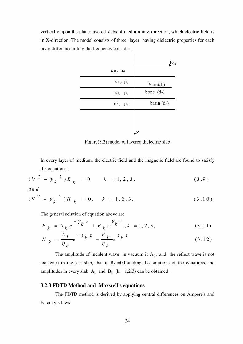
34
vertically upon the plane-layered slabs of medium in Z direction, which electric field is
in X-direction. The model consists of three layer having dielectric properties for each
layer differ according the frequency consider .
Figure(3.2) model of layered dielectric slab
In every layer of medium, the electric field and the magnetic field are found to satisfy
the equations :
2 2 0 , 1 , 2 , 3 , ( 3 . 9 )
2 2( ) 0 , 1 , 2 , 3 , ( 3 . 1 0 )
( )k
E kk
a n d
H kk k
γ
γ = =
∇ − = =
∇ −
The general solution of equation above are
, 1, 2 , 3 , ( 3 .1 1)
( 3 .1 2 )
z zk kE A e B e k
k k k
A Bz zk kk kH e e
kk k
γ γ
γ γ
η η
−= + =
−= −
The amplitude of incident wave in vacuum is A0 , and the reflect wave is not
existence in the last slab, that is B3 =0.founding the solutions of the equations, the
amplitudes in every slab Ak and Bk (k = 1,2,3) can be obtained .
3.2.3 FDTD Method and Maxwell's equations
The FDTD method is derived by applying central differences on Ampere's and
Faraday’s laws:
�� � �
�� � �
�� ��
�� � ��
Skin(d1)
bone (d2)
brain (d3)
Z
E0x
35
(3 .1 3 )
(3 .1 4 )
,
,
,
,
HE H yx z E xt y z
E H Hy x z E yt z x
HE Hyz z E zt x y
EH Eyx zt z y
H E Ey z xt x z
EH E yz xt y x
ε σ
ε σ
ε σ
µ
µ
µ
∂∂ ∂= − −
∂ ∂ ∂
∂ ∂ ∂= − −
∂ ∂ ∂∂∂ ∂
= − −∂ ∂ ∂
∂∂ ∂= −
∂ ∂ ∂
∂ ∂ ∂= −
∂ ∂ ∂∂∂ ∂
= −∂ ∂ ∂
The difference equations for F
x
∂
∂ and
F
t
∂
∂ are
( , , ) ( 1/ 2, , ) ( 1/ 2, , )n n nF i j k F i j k F i j k
x
∂ + − −=
∂ ∂ (3.15)
1/ 2 1/ 2( , , ) ( , , ) ( , , )n n nF i j k F i j k F i j k
t t
+ −∂ −=
∂ ∆ (3.16)
The specific absorption rate (SAR) is defined as the power dissipation rate
normalized by material density .
It can be shown that :
(3.17)1 2
.S A R J E Eσ
ρ ρ= =
�� ���
The SAR distribution within the body is highly inhomogeneous,Tissues
dielectric properties change with radio frequency. Many studies have been conducted to
determine the relationship between dielectric properties and frequency for different
types of biological tissues .
Changing the frequency and running the program, the dielectric properties has
been calculated. According to the assumption in research that the layer represents skin,
bone, and brain, the conductivity, relative permittivity, wavelength and penetration
depth have been evaluated for each layer.
36
The finite difference time domain (FDTD) method is a full-wave, dynamic, and
powerful solution tool for solving Maxwell’s equations, introduced by K.S. Yee. The
algorithm involves direct discriminations of Maxwell’s equations by writing the spatial
and time derivatives in a central finite difference form. The time-dependent Maxwell’s
curl equations in a homogenous dielectric medium are
The constants ε 0 and �0 are known as the permittivity and permeability of free space
andε r is the relative permittivity of the material.
3.2.4 Curl Equations in Cartesian Coordinates
Expanding the equation (3.18)
1
0
EH
t rε ε
∂= ∇×
∂ (3.20)
In Cartesian coordinate
0
1ˆ ˆ ˆ ˆ ˆ ˆ( ) ( ) ( )y y yx z z x z x
r
E H HE E H H H Hx y z x y z
t t t y z z x x yε ε
∂ ∂ ∂� �∂ ∂ ∂ ∂ ∂ ∂+ + = − + − + −� �
∂ ∂ ∂ ∂ ∂ ∂ ∂ ∂ ∂� �
Equating the vector components, we obtain :
0
0
0
1( )
1( )
1( )
yx z
r
y x z
r
yz x
r
HE H
t y z
E H H
t z x
HE H
t x y
ε ε
ε ε
ε ε
∂∂ ∂= −
∂ ∂ ∂
∂ ∂ ∂= −
∂ ∂ ∂
∂∂ ∂= −
∂ ∂ ∂
Similarly expanding(3.20)
1(3.18)
01
(3.19)
EH
t r
HE
t
ε ε
µ
∂= ∇ ×
∂
∂= − ∇ ×
∂
3.21)(
1HE
t µ
∂= − ∇ ×
∂

37
We obtain three more equations,
In 1-D, we assume Ey = 0 and Ez = 0 and no variation in the x-y plane, i.e.
0, 0x y
∂ ∂= =
∂ ∂
The equations reduced to
0
0 0
0
1( ) 0
1 1( )
1( ) 0
yx z
y z x x
yz x
EH E
t z y
H E E E
t x z z
EH E
t y x
µ
µ µ
µ
∂∂ ∂= − =
∂ ∂ ∂
∂ ∂ ∂ ∂= − = −
∂ ∂ ∂ ∂
∂∂ ∂= − =
∂ ∂ ∂
0 0
1 1( )y yx z
r r
E EE E
t y z zε ε ε ε
∂ ∂∂ ∂= − = −
∂ ∂ ∂ ∂ (3.24)
3.2.5 1D-FDTD Solution to Maxwell’s Equations .
In a simple one-dimensional case, we will consider the case where only the Ex
and Hy components exist. Equations above becomes:
0
1( 3 . 2 6 )y x
H E
t zµ
∂ ∂= −
∂ ∂
0
0
0
1( )
1( )
1( )
yx z
y z x
yz x
EH E
t z y
H E E
t x z
EH E
t y x
µ
µ
µ
∂∂ ∂= −
∂ ∂ ∂
∂ ∂ ∂= −
∂ ∂ ∂
∂∂ ∂= −
∂ ∂ ∂
3.22)(
3.23) (
0
1( 3 .2 5 )yx
r
HE
t zε ε
∂∂= −
∂ ∂
38
These equations represent a plane wave with the electric field orientated in the x-
direction and magnetic field oriented in the y-direction and traveling in the z-direction.
In the FDTD formulation, the central difference approximations for both the temporal
and spatial derivatives are obtained at ,z k z t n t= ∆ = ∆ for the first
equation:
1/ 2 1/ 2
0
( 1 / 2) ( 1 / 2)( ) ( ) 1(3.27)
n nn ny yx x
r
H k H kE k E k
t zε ε
+ − + − −−= −
∆ ∆
And for the second equation:
1 1/2 1/2
0
(3.28)( 1/ 2) ( 1/ 2) ( 1) ( )1
n n n ny y x x
H k H k E k E k
t zµ
+ + ++ − + + −= −
∆ ∆
Numerical error is minimized by making the following change as:
0
0
. ( 3 . 2 9 )x x
E Eε
µ=�
which bring the field quantities to similar levels. Implementing the changing of
variables, we obtain :
1/ 2 1/ 2
0
1 1/ 2 1/ 2
0
1( ) ( ) [ ( 1/ 2) ( 1/ 2)] (3.30)
1( 1/ 2) ( 1/ 2) [ ( 1) ( ) (3.31)
n n n n
x x y y
r
n n n n
y y x x
tE k E k H k H k
z
tH k H k E k E k
z
ε ε µ
ε µ
+ −
+ + +
∆= − + − −
∆
∆+ = + − + −
∆
� �
� �

39
3.2.6 Propagation simulate in media that have conductivity :
There are many media that also have a loss term specified by conductivity . This
loss term results in the attenuation of the propagating energy.
Once more we will start with the time-dependent Maxwell equation, but we will write
them in amore general form, which will allow us to simulate propagation in media that
have conductivity are
J is the current density which can also be written
.J Eσ=
where � is the conductivity., we get
The constants ε0 and �0 are known as the permittivity and permeability of free space
and ε r is the relative permittivity of the material.
The equations reduced to
Take the FDTD formulation, the central difference approximations for both the
temporal and spatial derivatives are obtained at ,z k z t n t= ∆ = ∆ for the
equation:
0
0
1 / 2 1/ 2 ( 1 / 2 ) ( 1 / 2 )( ) ( ) 1
1 / 2 1 / 2( ) ( )(3 .3 7 )
2
n nn n H k H kE k E k y yx xt zr
n nE k E kx x
r
ε ε
σε ε
+ − + − −−= − −
∆ ∆
+ −+−
0
(3.32)
1(3.33)
EH J
t
HE
t
ε
µ
∂= ∇ × −
∂
∂= − ∇ ×
∂
0 0
( )( ) 1( ) (3 .3 6 )yx
x
r r
H tE tE t
t z
σ
ε ε ε ε
∂∂= − −
∂ ∂
0 0
0
1(3.34)
1(3.35)
EH E
t r r
HE
t
σ
ε ε ε ε
µ
∂= ∇ × −
∂
∂= − ∇ ×
∂
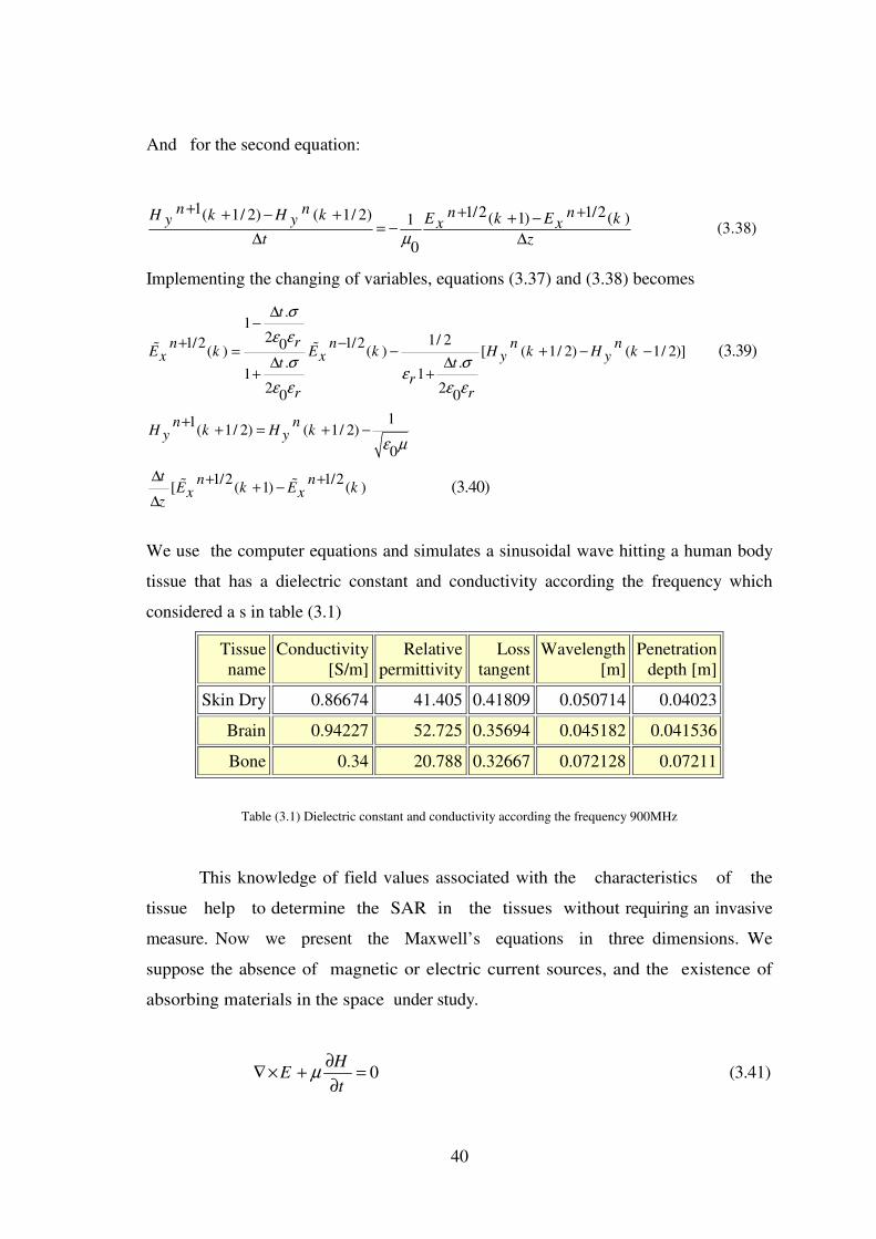
40
And for the second equation:
1 1/2 1/2( 1/ 2) ( 1/ 2) ( 1) ( )1(3.38)
0
n n n nH k H k E k E ky y x xt zµ
+ + ++ − + + −= −
∆ ∆
Implementing the changing of variables, equations (3.37) and (3.38) becomes
.1
2 1/ 21/2 1/20( ) ( ) [ ( 1/ 2) ( 1/ 2)]. .
1 12 20 0
11( 1/ 2) ( 1/ 2)
0
1/2 1/2[ ( 1) ( )
(3.39)
(3.40)
t
rn n n nE k E k H k H kx x y yt t
rr r
n nH k H ky y
t n nE k E kx x
z
σ
ε ε
σ σε
ε ε ε ε
ε µ
∆−
+ −= − + − −
∆ ∆+ +
++ = + −
∆ + ++ −
∆
� �
� �
We use the computer equations and simulates a sinusoidal wave hitting a human body
tissue that has a dielectric constant and conductivity according the frequency which
considered a s in table (3.1)
Tissue name
Conductivity [S/m]
Relative permittivity
Loss tangent
Wavelength [m]
Penetration depth [m]
Skin Dry 0.86674 41.405 0.41809 0.050714 0.04023
Brain 0.94227 52.725 0.35694 0.045182 0.041536
Bone 0.34 20.788 0.32667 0.072128 0.07211
Table (3.1) Dielectric constant and conductivity according the frequency 900MHz
This knowledge of field values associated with the characteristics of the
tissue help to determine the SAR in the tissues without requiring an invasive
measure. Now we present the Maxwell’s equations in three dimensions. We
suppose the absence of magnetic or electric current sources, and the existence of
absorbing materials in the space under study.
0H
Et
µ∂
∇× + =∂
(3.41)
41
D
H Et
ε σ∂
∇× − =∂
(3.42)
Where the displacement vector D is related to the electric field through the complex
permittivity
0
( )r r
jσ
ε ω εω ε
∗ = − (3.43)
Where is the angular frequency, this gives
expressions of the form
11
1 1 1 1
2 2 2 2
2 2
1 1( , , ) ( , , )
2 2
1 1 1 1 1 1 1 1( , , ( , , ( , , ( , ,
2 2 2 2 2 2 2 2( ) ( )
n n
z z z
n n n n
y y x y
z z
E i j k E i j k
H i j k H i j k H i j k H i j k
x y
ε
ε ε
−
− − − −
+ − +
+ + − − + + + − − +− −
∆ ∆
(3.44)
1 1
2 21 1 1 1
( , , ) ( , , )2 2 2 2
1 1 1 1( 1, , ) ( , , ( , 1, ) ( , ,
2 2 2 2( ) ( )
n n
z z
n n n n
y y y y
E i j k H i j k
E i j k E i j k E i j k E i j kt t
x yµ µ
+ +
+ + = + +
+ + − + + + − +∆ ∆
− +∆ ∆
(3.45)
The various components of the fields are evaluated on the basis of
neighboring components for each lapse of time and each cell in the modeling area. This
method works in the time domain and allows direct visualization of electromagnetic
fields.
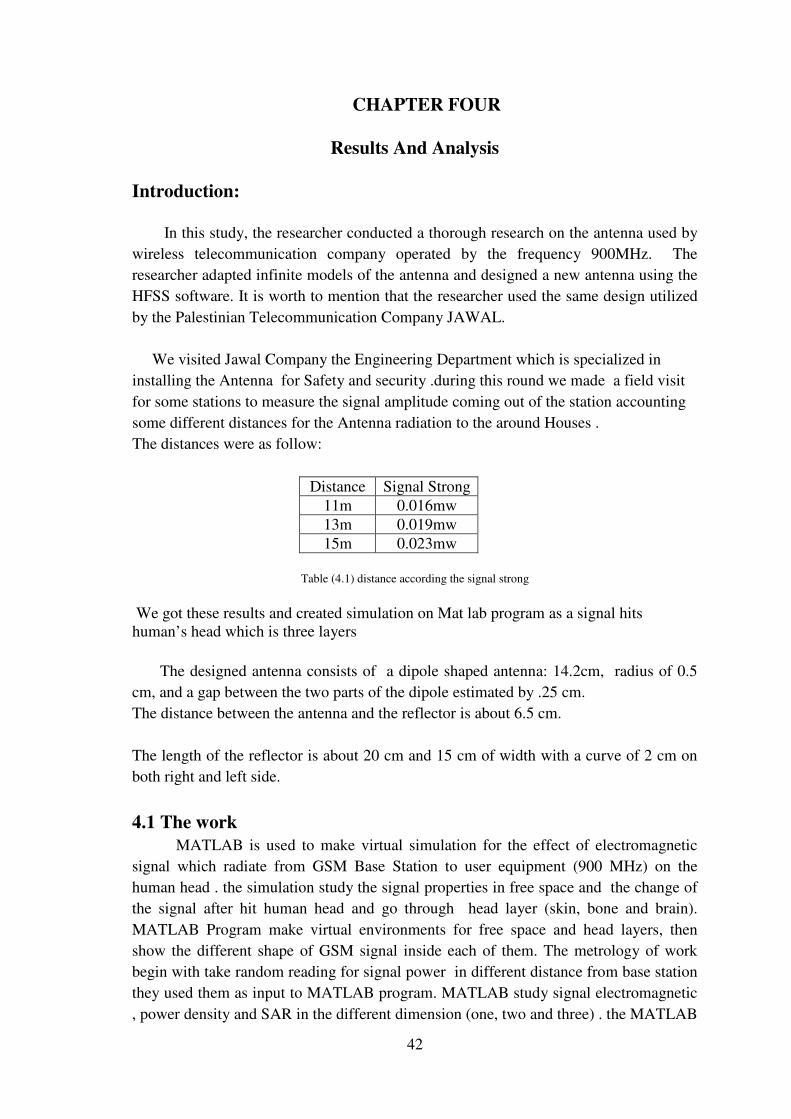
42
CHAPTER FOUR
Results And Analysis
Introduction:
In this study, the researcher conducted a thorough research on the antenna used by
wireless telecommunication company operated by the frequency 900MHz. The
researcher adapted infinite models of the antenna and designed a new antenna using the
HFSS software. It is worth to mention that the researcher used the same design utilized
by the Palestinian Telecommunication Company JAWAL.
We visited Jawal Company the Engineering Department which is specialized in
installing the Antenna for Safety and security .during this round we made a field visit
for some stations to measure the signal amplitude coming out of the station accounting
some different distances for the Antenna radiation to the around Houses .
The distances were as follow:
Distance Signal Strong 11m 0.016mw 13m 0.019mw 15m 0.023mw
Table (4.1) distance according the signal strong
We got these results and created simulation on Mat lab program as a signal hits human’s head which is three layers
The designed antenna consists of a dipole shaped antenna: 14.2cm, radius of 0.5
cm, and a gap between the two parts of the dipole estimated by .25 cm.
The distance between the antenna and the reflector is about 6.5 cm.
The length of the reflector is about 20 cm and 15 cm of width with a curve of 2 cm on
both right and left side.
4.1 The work
MATLAB is used to make virtual simulation for the effect of electromagnetic
signal which radiate from GSM Base Station to user equipment (900 MHz) on the
human head . the simulation study the signal properties in free space and the change of
the signal after hit human head and go through head layer (skin, bone and brain).
MATLAB Program make virtual environments for free space and head layers, then
show the different shape of GSM signal inside each of them. The metrology of work
begin with take random reading for signal power in different distance from base station
they used them as input to MATLAB program. MATLAB study signal electromagnetic
, power density and SAR in the different dimension (one, two and three) . the MATLAB
43
code use FDTD Method as main class on it analysis. The next sections show
electromagnetic, power density and SAR at the different distance that we take on one
dimension and how the signal will arrive to zero at brain to provide that its safety for
human then certain this result in two and three dimension.
The general idea of the program show the electromagnetic of GSM signal in free
space and after strikes the human head interface, which must propagates more slowly,
and amplitude must decrease through skin, bone until arrived to zero in brain. The same
concepts for power density and SAR with variation on amplitude
The present approach focuses on the investigation of GSM radiofrequency
electromagnetic fields effects of two different specific absorption rate (SAR)
distributions on human head and power density. Matlab script used Finite-Difference
Time-Domain (FDTD) to calculate SAR and power density.
1-D FDTD code in Matlab
This part contains a code script written in Matlab, in which the 1-D FDTD algorithm
is implemented. An electromagnetic pulse is radiated from a source located in free
space. The source waveform is a sinusoidal shaped pulse, where implementation by
Matlab as directional dipole model. This wave travelling in free space and strikes
human head. When the wave strikes the interface, a fraction of the incoming wave is
reflected, and a fraction is transmitted into the head layers. The amplitude of the
reflected and transmitted waves, relative to the incident wave, is described by the
reflection coefficient � and the transmission coefficient �, which relate the amplitudes of
the E field waves. The fields Ez, Hz, Power density and SAR are simulated along the
line X =Y = 0, i.e. propagation along the ˆz axis during free space and the 3 head layers
l (skin, bone, brain). The next section shoe that the computational results which meet
the international safety guidelines for human health.
2-D FDTD code in Matlab
Matlab simulation shows the 2-D wave in free space hitting a head surface (right side),
with the source at the centre. The results were supportive to the result in one diminsion.
3-D FDTD code in Matlab
Its provide Analysis of specific absorption rate (SAR) generated by half wave
radiating dipole antenna inside a spherical inhomogeneous human head model at the
frequency range 900 MHz using finite difference in time domain (FDTD) method. The
human head is modeled consisting of a uniform core representing human brain,
surrounded by two spherical shells representing skin and bone. Also the effect of
Electromagnetic field and power density is studied. Simulation in the next sections
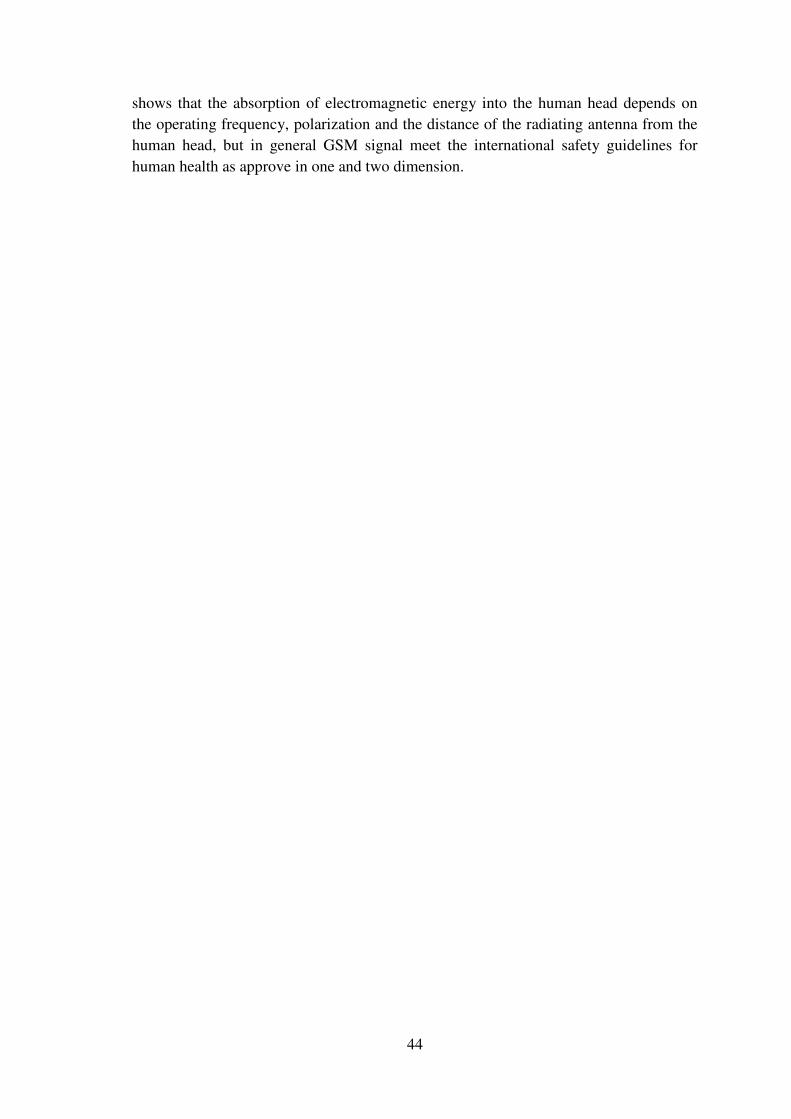
44
shows that the absorption of electromagnetic energy into the human head depends on
the operating frequency, polarization and the distance of the radiating antenna from the
human head, but in general GSM signal meet the international safety guidelines for
human health as approve in one and two dimension.
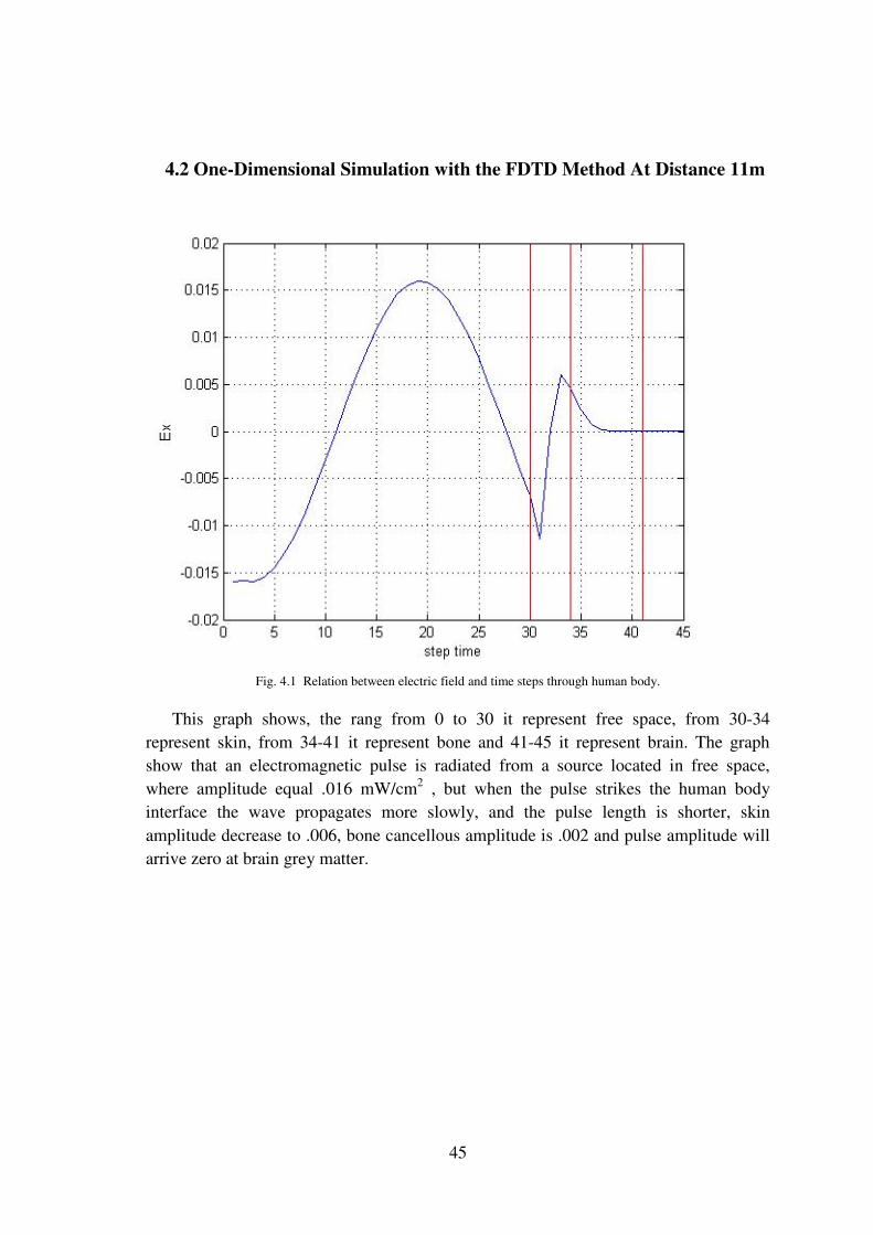
45
4.2 One-Dimensional Simulation with the FDTD Method At Distance 11m
Fig. 4.1 Relation between electric field and time steps through human body.
This graph shows, the rang from 0 to 30 it represent free space, from 30-34
represent skin, from 34-41 it represent bone and 41-45 it represent brain. The graph
show that an electromagnetic pulse is radiated from a source located in free space,
where amplitude equal .016 mW/cm2 , but when the pulse strikes the human body
interface the wave propagates more slowly, and the pulse length is shorter, skin
amplitude decrease to .006, bone cancellous amplitude is .002 and pulse amplitude will
arrive zero at brain grey matter.
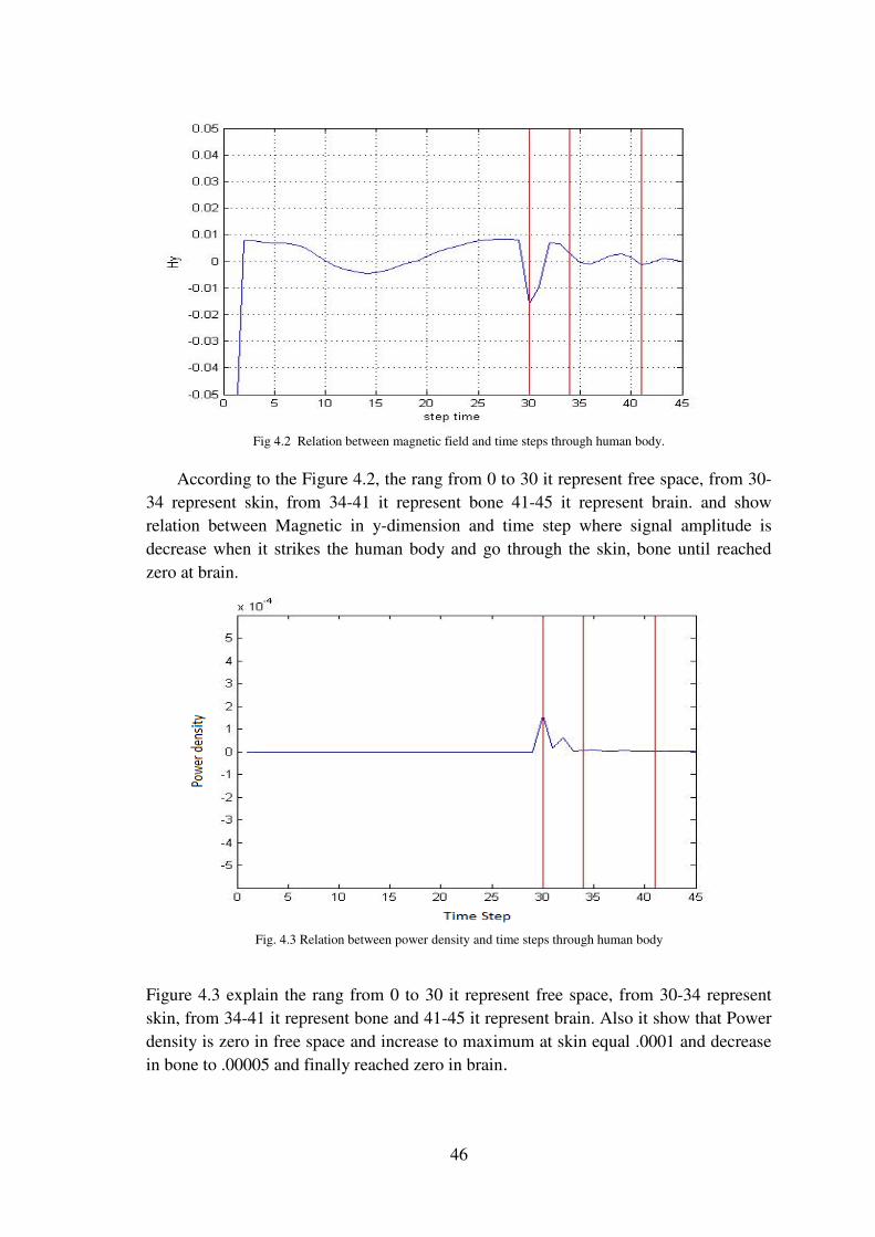
46
Fig 4.2 Relation between magnetic field and time steps through human body.
According to the Figure 4.2, the rang from 0 to 30 it represent free space, from 30-
34 represent skin, from 34-41 it represent bone 41-45 it represent brain. and show
relation between Magnetic in y-dimension and time step where signal amplitude is
decrease when it strikes the human body and go through the skin, bone until reached
zero at brain.
Fig. 4.3 Relation between power density and time steps through human body
Figure 4.3 explain the rang from 0 to 30 it represent free space, from 30-34 represent
skin, from 34-41 it represent bone and 41-45 it represent brain. Also it show that Power
density is zero in free space and increase to maximum at skin equal .0001 and decrease
in bone to .00005 and finally reached zero in brain.
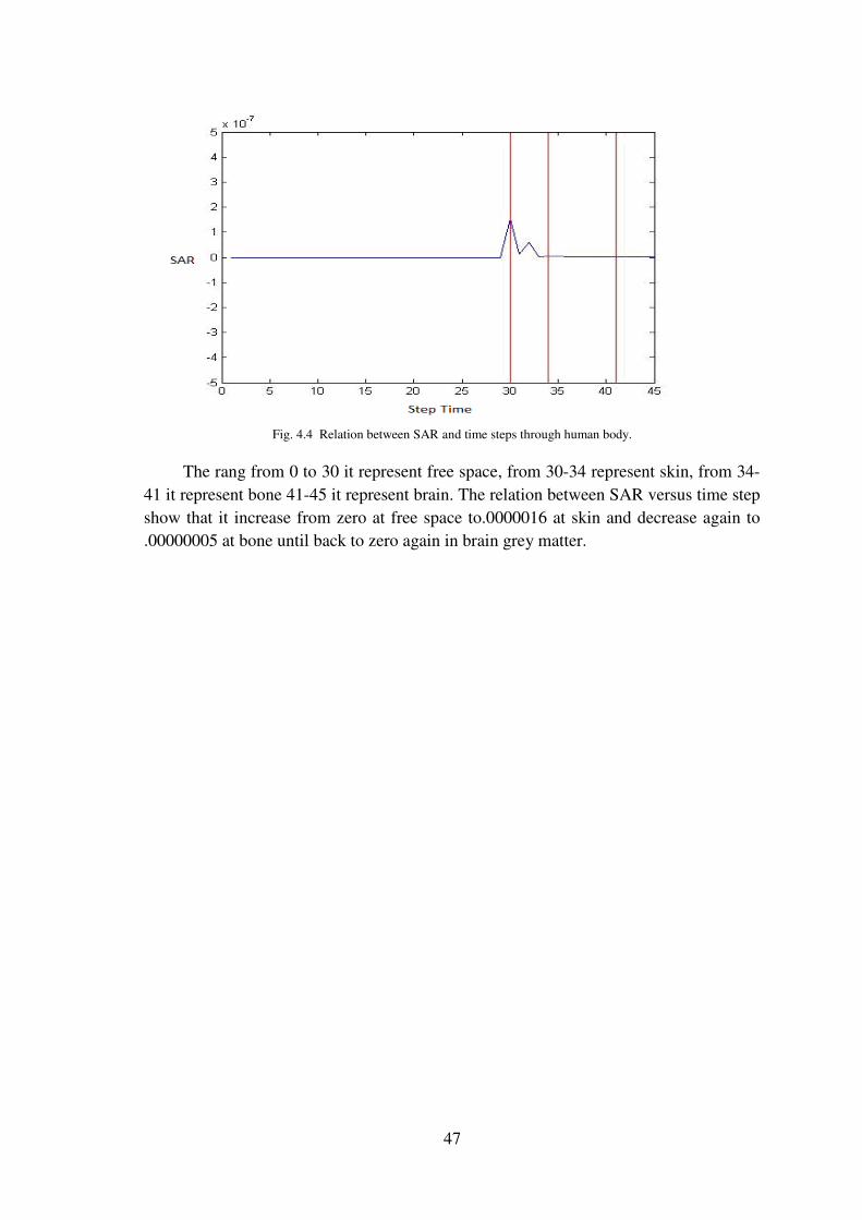
47
Fig. 4.4 Relation between SAR and time steps through human body.
The rang from 0 to 30 it represent free space, from 30-34 represent skin, from 34-
41 it represent bone 41-45 it represent brain. The relation between SAR versus time step
show that it increase from zero at free space to.0000016 at skin and decrease again to
.00000005 at bone until back to zero again in brain grey matter.
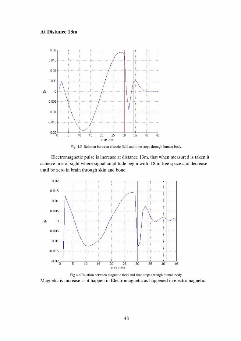
48
At Distance 13m
Fig. 4.5 Relation between electric field and time steps through human body.
Electromagnetic pulse is increase at distance 13m, that when measured is taken it
achieve line of sight where signal amplitude begin with .18 in free space and decrease
until be zero in brain through skin and bone.
Fig 4.6 Relation between magnetic field and time steps through human body.
Magnetic is increase as it happen in Electromagnetic as happened in electromagnetic.
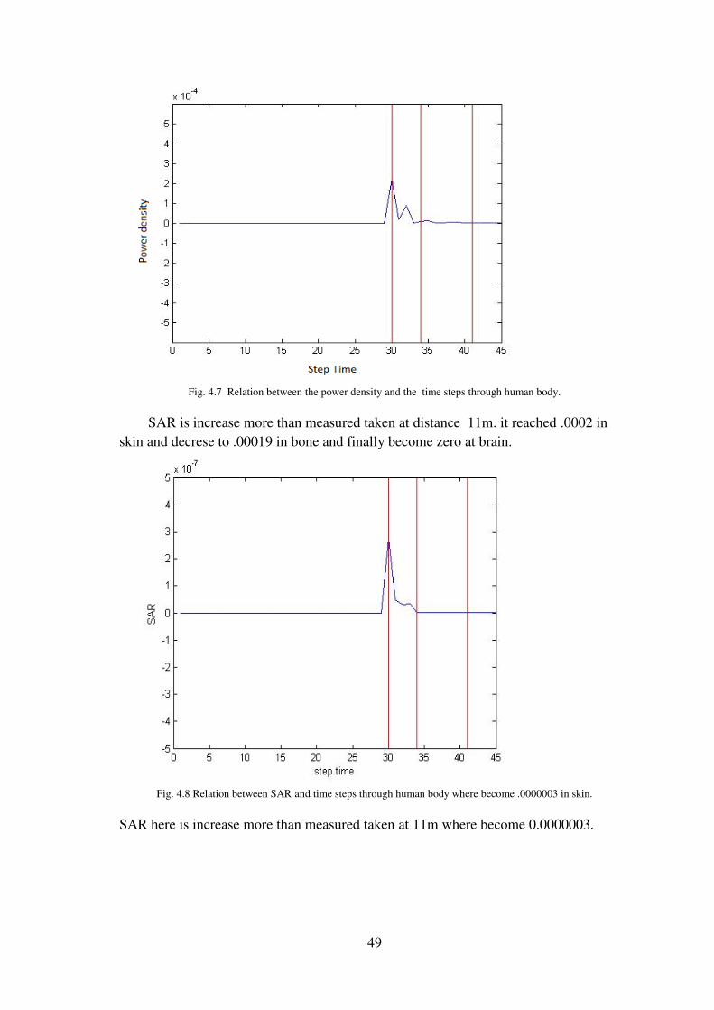
49
Fig. 4.7 Relation between the power density and the time steps through human body.
SAR is increase more than measured taken at distance 11m. it reached .0002 in
skin and decrese to .00019 in bone and finally become zero at brain.
Fig. 4.8 Relation between SAR and time steps through human body where become .0000003 in skin.
SAR here is increase more than measured taken at 11m where become 0.0000003.
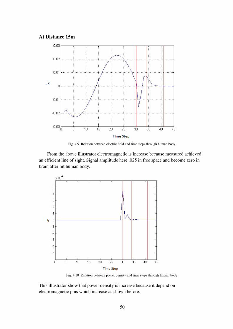
50
At Distance 15m
Fig. 4.9 Relation between electric field and time steps through human body.
From the above illustrator electromagnetic is increase because measured achieved
an efficient line of sight. Signal amplitude here .025 in free space and become zero in
brain after hit human body.
Fig. 4.10 Relation between power density and time steps through human body.
This illustrator show that power density is increase because it depend on
electromagnetic plus which increase as shown before.

51
Fig. 4.11 Relation between SAR and time steps through human body.
Its seen here that SAR increased as explained before
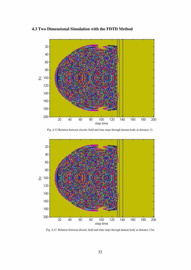
52
4.3 Two Dimensional Simulation with the FDTD Method
Fig. 4.12 Relation between electric field and time steps through human body at distance 11.
Fig. 4.13 Relation between electric field and time steps through human body at distance 13m

53
Fig. 4.14 Relation between electric field and time steps through human body at distance 15m.
According to the above graphs, the rang from 100-130 it represent free space,
from 130-134 represent skin, from 134-141 it represent bone 141-145 it represent brain.
These graphs shows that An electromagnetic pulse is radiated from a source located in
free space, but when the pulse strikes the human body interface. Notice that the wave
propagates more slowly, and the pulse length is shorter.

54
4.4 3-Dimensional Simulation with the FDTD Method
Fig 4.15 Relation between Electric field in free space and time steps through human body at distance 11m
Fig 4.16 Relation between Electric field in free space and time steps through human body at distance 13m
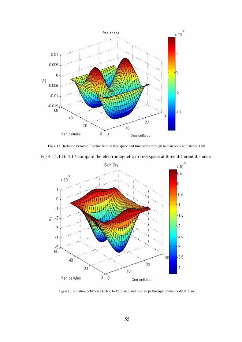
55
Fig 4.17 Relation between Electric field in free space and time steps through human body at distance 15m.
Fig 4.15,4.16,4.17 compare the electromagnetic in free space at three different distance
Fig 4.18 Relation between Electric field in skin and time steps through human body at 11m.

56
Fig 4.19 Relation between Electric field in skin and time steps through human body at 13m.
Fig 4.20 Relation between Electric field in skin and time steps through human body at 15 m.
Fig 4.18,4.19,4.20 compare the electromagnetic inside skin at three different distance
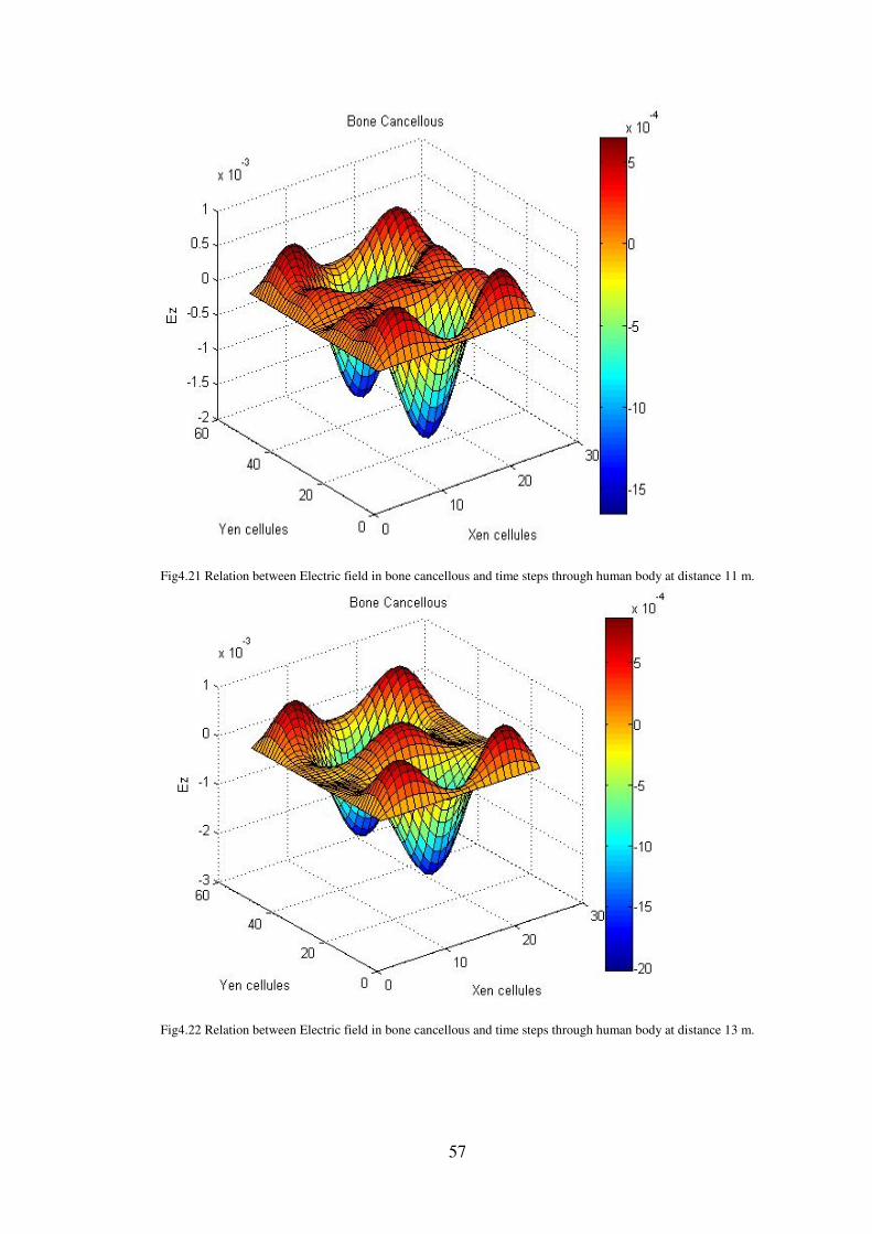
57
Fig4.21 Relation between Electric field in bone cancellous and time steps through human body at distance 11 m.
Fig4.22 Relation between Electric field in bone cancellous and time steps through human body at distance 13 m.
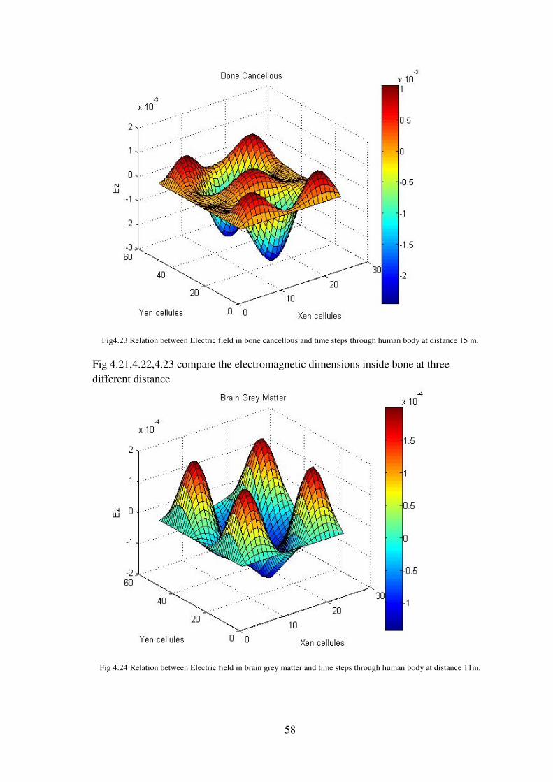
58
Fig4.23 Relation between Electric field in bone cancellous and time steps through human body at distance 15 m.
Fig 4.21,4.22,4.23 compare the electromagnetic dimensions inside bone at three
different distance
Fig 4.24 Relation between Electric field in brain grey matter and time steps through human body at distance 11m.

59
Fig 4.25 Relation between Electric field in brain grey matter and time steps through human body at distance 13m.
Fig 4.26 Relation between Electric field in brain grey matter and time steps through human body at distance 15m.
Fig 4.24,4.25,4.26 compare the electromagnetic dimensions inside brain at three
different distance
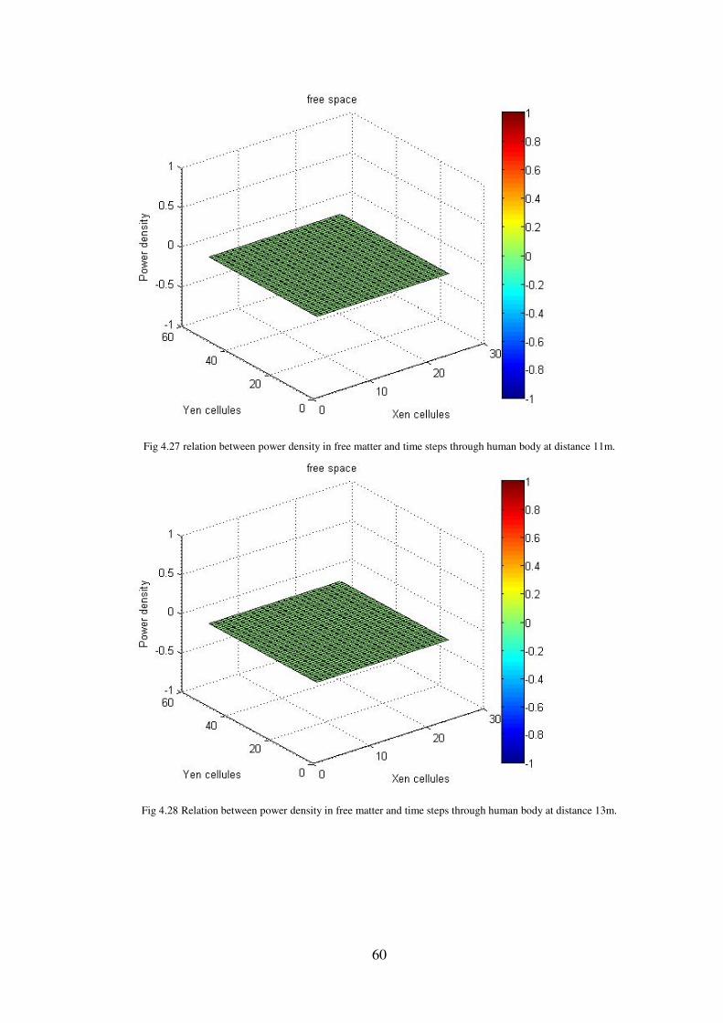
60
Fig 4.27 relation between power density in free matter and time steps through human body at distance 11m.
Fig 4.28 Relation between power density in free matter and time steps through human body at distance 13m.
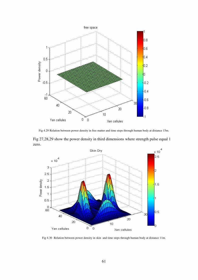
61
Fig 4.29 Relation between power density in free matter and time steps through human body at distance 15m.
Fig 27,28,29 show the power density in third dimensions where strength pulse equal 1
zero.
Fig 4.30 Relation between power density in skin and time steps through human body at distance 11m.
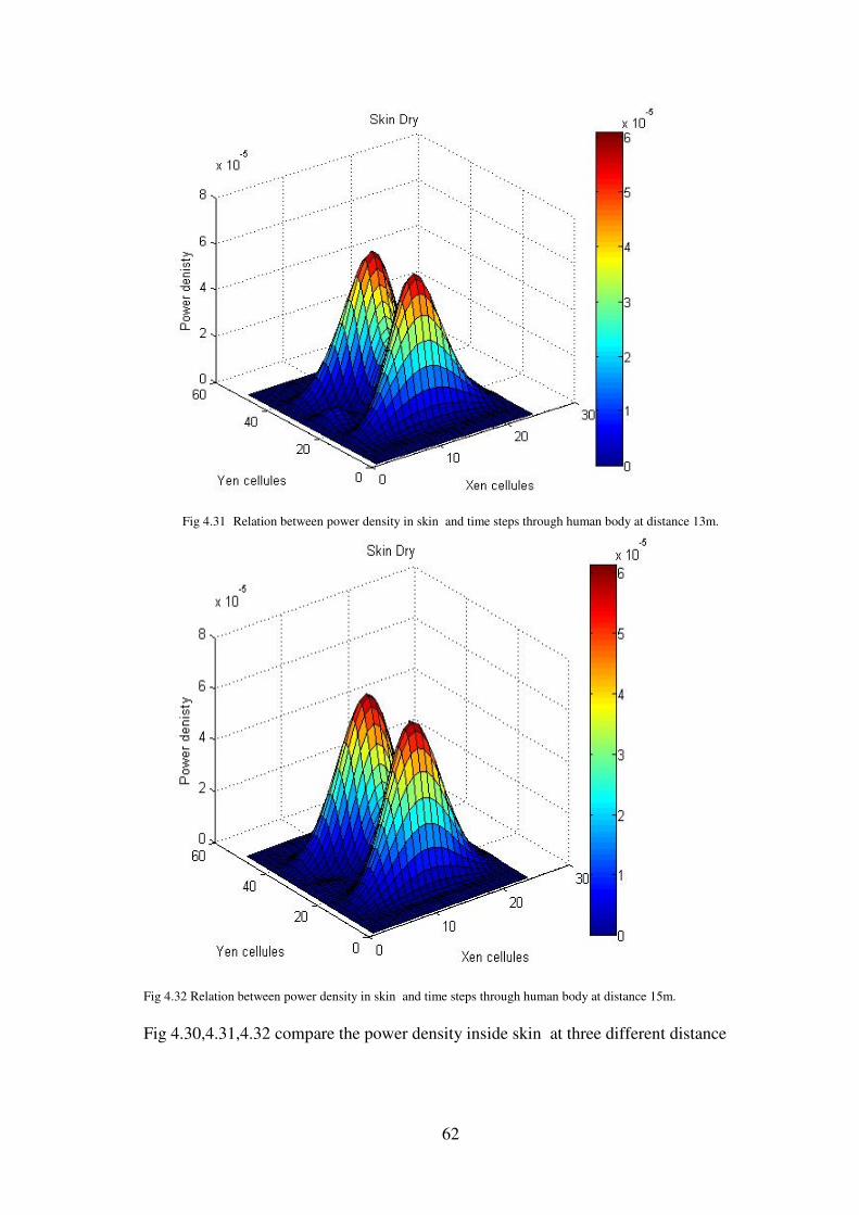
62
Fig 4.31 Relation between power density in skin and time steps through human body at distance 13m.
Fig 4.32 Relation between power density in skin and time steps through human body at distance 15m.
Fig 4.30,4.31,4.32 compare the power density inside skin at three different distance

63
Fig 4.33 Relation between power density in bone cancellous and time steps through human body at distance 11m
Fig 4.34 Relation between power density in bone cancellous and time steps through human body at distance 13m
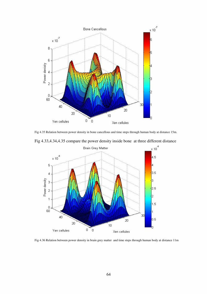
64
Fig 4.35 Relation between power density in bone cancellous and time steps through human body at distance 15m.
Fig 4.33,4.34,4.35 compare the power density inside bone at three different distance
Fig 4.36 Relation between power density in brain grey matter and time steps through human body at distance 11m
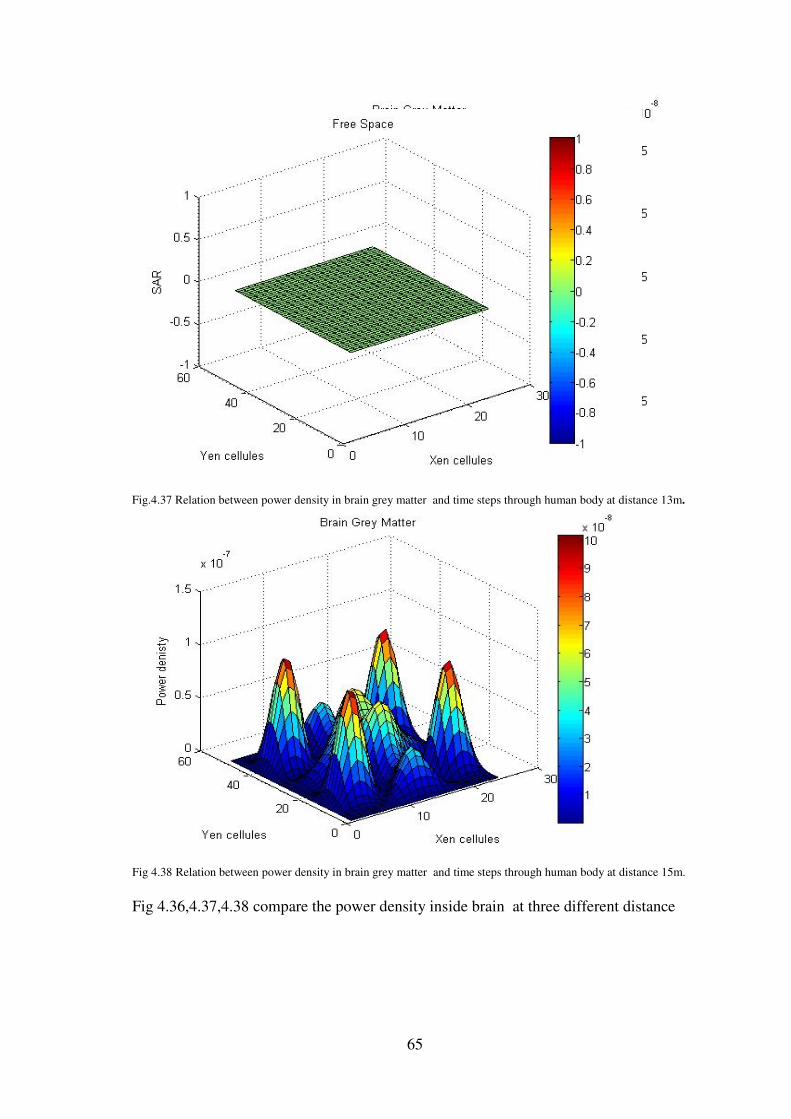
65
Fig.4.37 Relation between power density in brain grey matter and time steps through human body at distance 13m.
Fig 4.38 Relation between power density in brain grey matter and time steps through human body at distance 15m.
Fig 4.36,4.37,4.38 compare the power density inside brain at three different distance
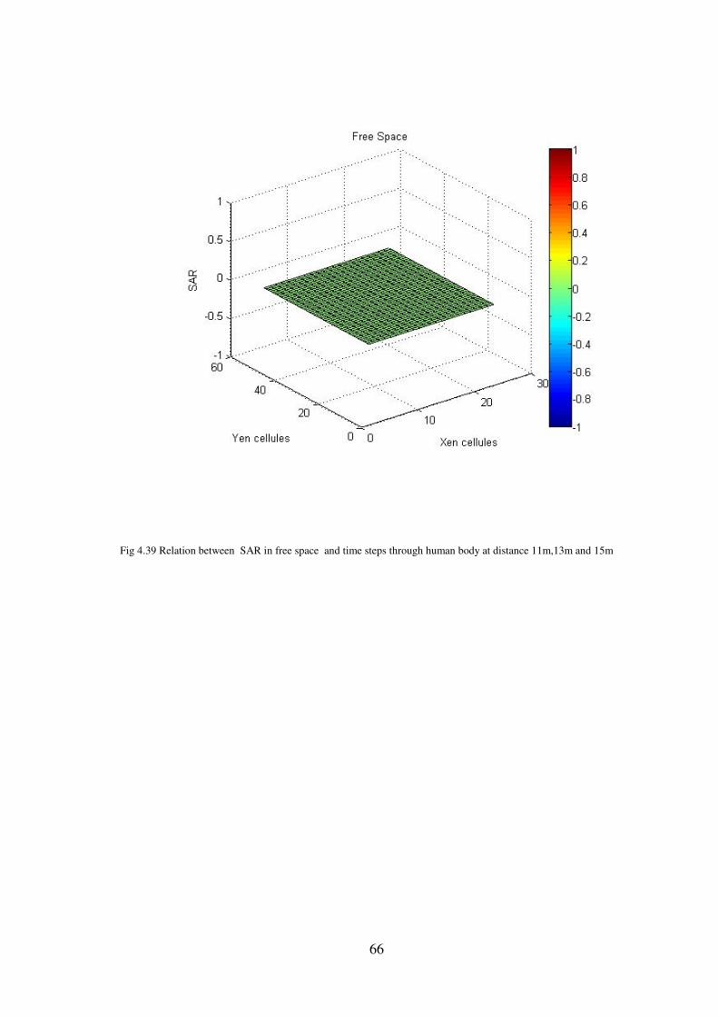
66
Fig 4.39 Relation between SAR in free space and time steps through human body at distance 11m,13m and 15m
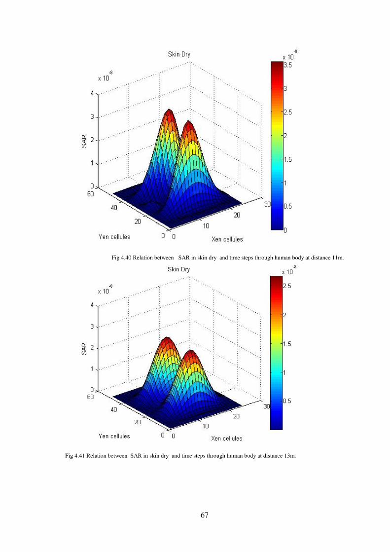
67
Fig 4.40 Relation between SAR in skin dry and time steps through human body at distance 11m.
Fig 4.41 Relation between SAR in skin dry and time steps through human body at distance 13m.
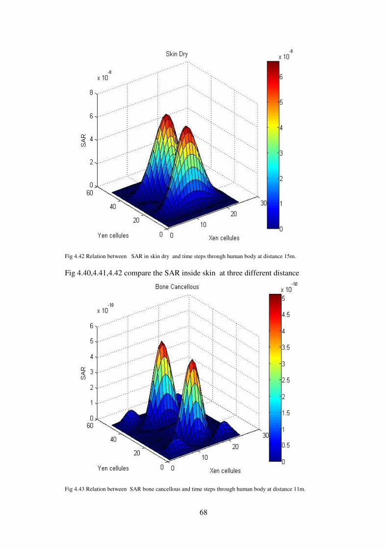
68
Fig 4.42 Relation between SAR in skin dry and time steps through human body at distance 15m.
Fig 4.40,4.41,4.42 compare the SAR inside skin at three different distance
Fig 4.43 Relation between SAR bone cancellous and time steps through human body at distance 11m.
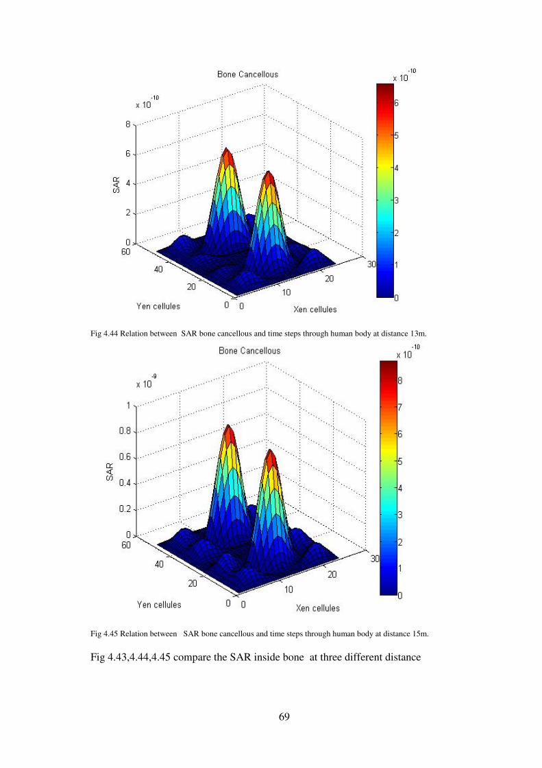
69
Fig 4.44 Relation between SAR bone cancellous and time steps through human body at distance 13m.
Fig 4.45 Relation between SAR bone cancellous and time steps through human body at distance 15m.
Fig 4.43,4.44,4.45 compare the SAR inside bone at three different distance
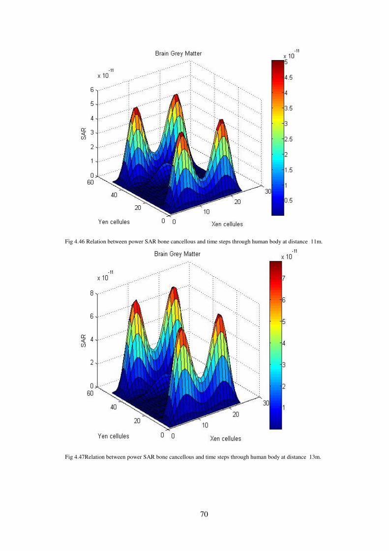
70
Fig 4.46 Relation between power SAR bone cancellous and time steps through human body at distance 11m.
Fig 4.47Relation between power SAR bone cancellous and time steps through human body at distance 13m.
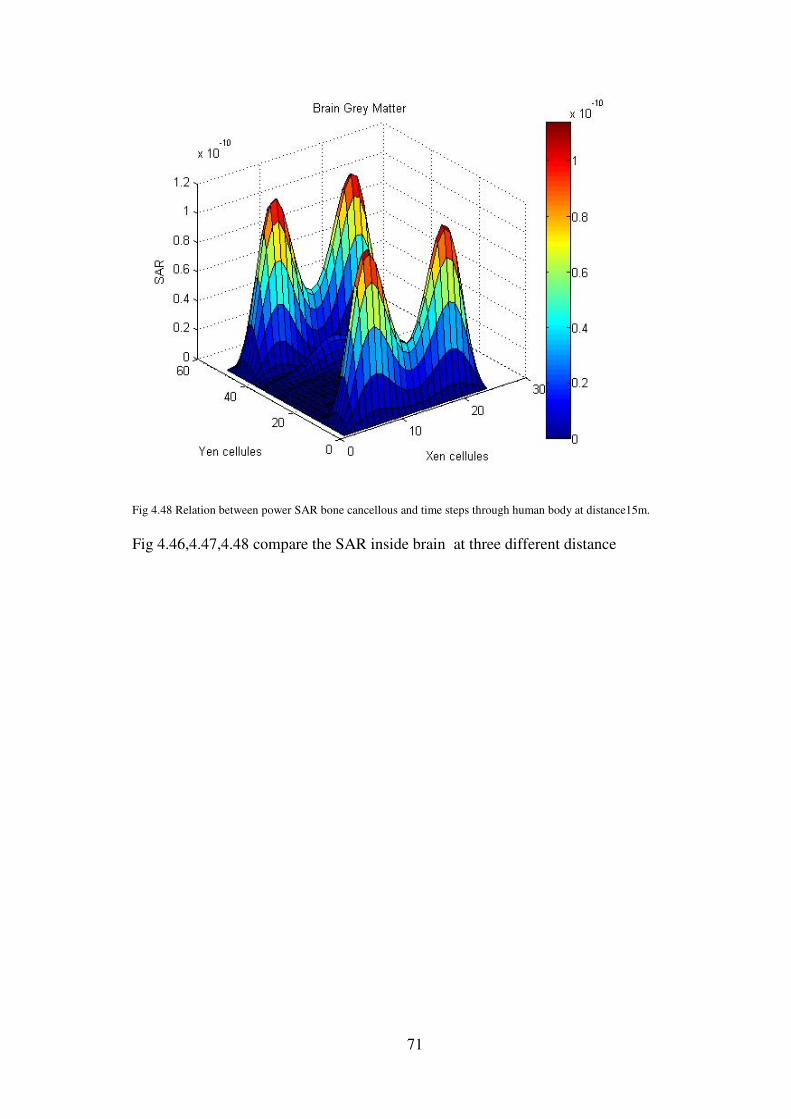
71
Fig 4.48 Relation between power SAR bone cancellous and time steps through human body at distance15m.
Fig 4.46,4.47,4.48 compare the SAR inside brain at three different distance
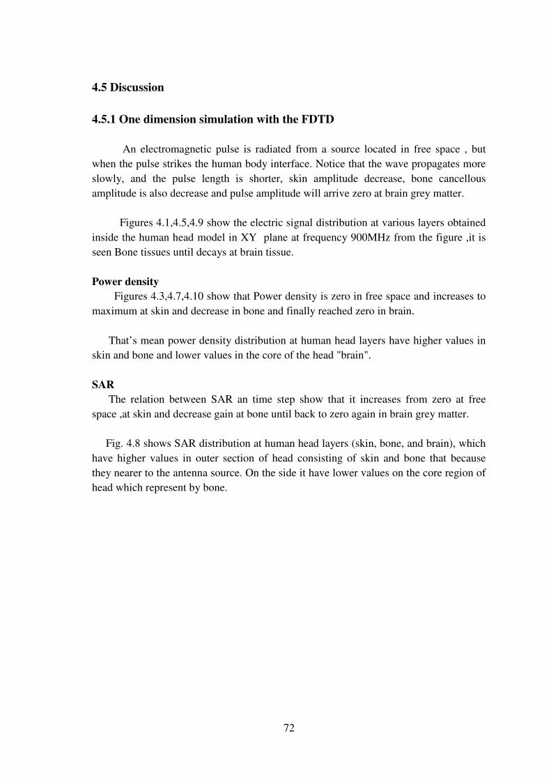
72
4.5 Discussion
4.5.1 One dimension simulation with the FDTD
An electromagnetic pulse is radiated from a source located in free space , but
when the pulse strikes the human body interface. Notice that the wave propagates more
slowly, and the pulse length is shorter, skin amplitude decrease, bone cancellous
amplitude is also decrease and pulse amplitude will arrive zero at brain grey matter.
Figures 4.1,4.5,4.9 show the electric signal distribution at various layers obtained
inside the human head model in XY plane at frequency 900MHz from the figure ,it is
seen Bone tissues until decays at brain tissue.
Power density
Figures 4.3,4.7,4.10 show that Power density is zero in free space and increases to
maximum at skin and decrease in bone and finally reached zero in brain.
That’s mean power density distribution at human head layers have higher values in
skin and bone and lower values in the core of the head "brain".
SAR
The relation between SAR an time step show that it increases from zero at free
space ,at skin and decrease gain at bone until back to zero again in brain grey matter.
Fig. 4.8 shows SAR distribution at human head layers (skin, bone, and brain), which
have higher values in outer section of head consisting of skin and bone that because
they nearer to the antenna source. On the side it have lower values on the core region of
head which represent by bone.
73
4.5.2 Three dimension simulation with FDTD
Figures 4.15,4.16,4.17 show the Electric z in third dimensions where strength pulse
equal and decrees with distance in free space.
Figures 4.18,4.19,4.20 show the Electric z in third dimensions where strength pulse
inside skin is decrease, when the pulse strikes the human body interface.
Figures 4.21,4.22,4.23 show the Electric z in third dimensions inside bone where
strength signal is decrease than skin.
Figures 4.24,4.25,4.26 show the Electric z in third dimensions inside brain where
strength signal around zero.
A large amount of energy transfer from antenna to head but because there mismatching
between free space region and skin most of the signal reflected and some of it
transmitted ,also we have the same principle between skin-bone and bone-brain as
shown in the figures from free space to brain.
SAR
Figures 4.40,4.41,4.42 show the SAR in third dimensions
Figures 4.43,4.44,4.45 show the SAR in third dimensions inside skin where strength signal is
decrease.
Figures 4.46,4.47,4.48 show the SAR in third dimensions inside bone where strength
signal is more decrease
Figures 4.49,4.50,4.51 show the SAR in third dimensions inside brain where strength
signal equal approximately zero
shows that power absorbed by skin have maximum values comparing to the value
in bone as illustrated in bone and core of the head in brain figures, that come from the
fact that SAR have linear relation with electric field and conductivity which the highest
value in the skin as illustrated in brain figures. also SAR have inversed linear relation
with mass density which have the highest value in the brain.
Power density
Figures 4.27,4.28,4.29 show the power density in third dimensions where strength pulse
equals zero.
Figures 4.30,4.31,4.32 show the power density in third dimensions inside skin brain
where strength signal around zero.
Figures 4.33,4.34,4.35 show the power density in third dimensions inside bone where
strength signal is decrees than skin.
Figures 4.36,4.37,4.38 show the power density in third dimensions inside bone where
strength signal equal approximately zero.
74
So power density will have the same response of SAR with different in the
amplitude that because its part of SAR function.
75
CHAPTER FIVE
Discussion and Conclusion
5.1 Results:
The effect of electromagnetic waves have been examined concerning the one
dimensions, two dimension, and three dimensions using Matlab software. Through
simulating electromagnetic waves emitting from antenna about 30 cm away from
human’s head, the behavior of the wave from the moment of emission to the moment of
infiltrating the scalp then the brain is examined. Following that, the researcher identifies
the absorption rate in each single layer (skin, bone, and the brain) with the following
findings: the highest level of absorption takes place right in the skin layer and then the
brain layer given the biological structure of the cells.
The energy density emitted from the transmission stations and the human capacity is
also studied.
5.1.1 One dimension simulation with the FDTD method
Electric field in x direction
Fig.4.1 shows the electric signal distribution at various layers obtained inside the human
head model in XY plane at frequency 900MHz from the figure, it is seen Bone tissues
until decays at brain tissue.
Power density
Fig. 4.3 shows power density distribution at human head layers, which have higher
values in skin and bone and lower values in the core of the head "brain"
SAR
Fig. 4.4 shows SAR distribution at human head layers (skin, bone, and brain), which
have higher values in outer section of head consisting of skin and bone that because
they nearer to the antenna source. On the side it have lower values on the core region of
head which represent by bone
5.1.2 Three dimension simulation with the FDTD method
Electric field in x direction
A large amount of energy transfer from antenna to head but because there mismatching
between free space region and skin most of the signal reflected and some of it
transmitted ,also we have the same principle between skin-bone and bone-brain as
shown in the figures from Fig. 4.8 to Fig.4.20.

76
SAR
Fig 4.22 shows that power absorbed by skin have maximum values comparing to the
value in bone as illustrated in fig. 4.23 and core of the head in fig 4.24, that come from
the fact that SAR have linear relation with electric field and conductivity which the
highest value in the skin as illustrated in Fig 4.8.also SAR have inversed linear relation
with mass density which have the highest value in the brain.
Power density
Power density will have the same response of SAR with different in the amplitude that
because its part of SAR function
5.2 Conclusion
The evaluation of human exposure to new telecommunication systems, which are
becoming more and more widespread, has become an important issue. In fact, these new
systems usually operate a rather complex environment where many field sources and
scattering objects are present. In this situation, accurate investigations are needed to
assess if human exposure can give rise to health risks and to verify if existing protection
standards are still adequate.
In this study, the exposure of human head to the electromagnetic waves radiated by
abase station antenna.the exposure has been analyzed coupling the FDTD method and
with using matlab program.
In analytical assumption, three-layered structure representing simplified model of
human body tissue irradiated by mobile phone base station, is investigated. The layers
represent the skin, bone and brain.
FDTD is used to study the distribution of EM field in the body tissue, the absorbent
power, and SAR distribution. it is found that the fields penetrates the skin and attenuates
rapidly till they reach zero at the organs layer. Absorbent power and SAR have
maximum values at the skin layer.
5.3 Future work
Throughout this study, the researcher examines the effect resulting from the GSM
900MHz sector antenna in the wireless services. It is the hope of the researcher to
present an a noticeable advancement in the study of the effect of the fourth generation
electromagnetic antenna in the wireless services. It is also the hope of the researcher to
find ways to reduce the risks resulting from the frequencies emitted from transmission
stations in wireless services.
Study the effect of EM waves produced from mobile phones base station on life
tissue by using rate as experimental study.
77
References:
[1] K. David Cheng, Field and Wave Electromagnetic; Addison-Wesley Publishing Company Inc, New York, Edition 2, 1998.
[2] C.Y. William, Mobile Cellular Telecommunications Systems; Mc Graw-Hill
,New York, pp 45, 1999.
[3] J.D. Kraus and K. R. Carver, Electromagnetic; Mc Graw-Hill, New York, pp
648-650, 1973.
[4] C.A Balanis, Advanced Engineering Electromagnetic; Wiley, New ork,Vol.31,
PP-24-26,1989.
[5] H.C. Christensen and J. Schuz, and M. Kosteljanetz, Cellular Telephone Use
and Risk of Acoustic Neuroma; Am J Epidemiol,Vol.159, PP277-283, 2004.
[6] W. Retriev, Electromagnetic Fields and Public Health Base Stations and
Wireless Technologies; Health Topics A to Z. pp1-7, 2011.
[7] E.K Miller and G.J.Burk, Low –Frequency Computational Electromagnetic for
Antenna Analysis; Proc. IEEE,Vol.80, PP24-30, 1992.
[ 8] J .Ackson and John David, Classical Electromagnetic; (3rd ed.), John Wiley and
Sons, New York, 1999.
[9 ] M.A. Jensen and S.I Rahmat, EM Interaction of Handset Antennas and
AHuman in Personal Communications; IEEE,Vol.83, pp3-4 January 1995.
[10] M.A .Jensen and S.I Rahmat, EM Interaction of Handset Antennas and aHuman
in Personal Communication; IEEE,Vol.83, pp7-13 January 1995.
[11] M.I .Skolnik, Introduction to Radar System; Mc Graw-Hill, New York, pp320-
325,1962.
[12] R.A Chatterjee, Antenna Theory and Practice; New Age International, New
Delhi pp1-4, 2001.
[13] T. M El-dabe, Effect of Microwave Heating on The Thermal States of Biological Tissues, African Journal of Biotechnology; vol.2(11) 2003.
[14] D.M.Sullivan, Electromagnetic Simulation Using the FDTD Method; IEEE
Press, NewYork, 2000.
78
[15] K. R. Umashankar and A. Taflove, A novel Method to Analyze Electromagnetic
Scattering of Complex Objects; IEEE Transactions on Electromagnetic
Compatibility, 397–405.1982.
[16] D.I. Mbylow, FDTD Calculation of The Whole Body Averaged SAR in an
Anatomically Realistic Voxel Model of The Human Body From 1MHz to 1GHz;
p.j.phys.Med.Biol.pp 17-22, 2003.
[17] L.S.Selcuk Paker, FDTD Evaluation of The SAR Distribution in a Human Head
Near a Mobile Cellular Phone; IEEE Trans , Electromagnetic, PP-85-89, 1998.
[18] W.R . Adey, Bio-Effects of Communication Fields; New York , Chapman and
Hall, pp97-100, 1997.
[19] K.C Buzov, Ecological Aspects of Electromagnetic Radiations Emitted by Mobile Stations of Communication Means; Med.Tr.Prom-Ekol,9:17-19, 1996.
[20] F.R Connor, Introductory Topics in Electronics and Telecommunication Antennas; Edward Arnold , New York,Vol.4, PP2-4, 1989.
[21] C. U.P. Eulitz and P. Freude, and G. Elbert, Mobile Phones Modulate Response Patterns of Human Brain Activity; Neuro Report, Vol. 9, PP-3229-3232, 1998.
[22] G.J. Hyland, Physics and Biology of Mobile Telephony; Lancet Nov ,Vol.356, PP-1833-1836, 2000.
[23] H. S. N. Lai, Neurological Effects of Radiofrequency Electromagnetic Radiation; University of Vienna, Austria, 1998.
[24] k .y. Fujimoto, Mobile Antenna Systems; hand book Artech House , INC ,British Library, pp45-50, 1999.
[25] E.J Johannes, and K.A Sukul, High –Energy Extracorporeal Shock Wave
Treatment of Non-unions; Clin Orthop and Rel Resch, 102-111, 2001.
[26] E. Proksch, and J.M Brandner, and J.M Jensen, The Skin: An Indispensable
Barrier; Vol.17, PP-1063-1072, 2008.
[27] K.A. Hoehn, and E.l Nicpon, Human Anatomy & Physiology; (7th Edition).
San Francisco: Benjamin Cummings. ISBN 0805359095, 2007.
[28] H .Derrickson and T.O Gerard, Principles of Anatomy and Physiology; Wiley,
New York, 12 TH Eidition, PP922-930, 2005.
79
[29] D.P.Pelvig, H . Pakkenberga and Stark, AK; Pakkenberg, Neocortical Glial Cell
Numbers in Human Brains; Neurobiology of Aging ,Vol.29, PP-54-64, 2008.
[30] W.R .Adey, Bioeffects of Communication Fields; Chapman and Hall, New
York PP-97-100, 1997.
[31] J.S. Bridges and A.S. Ahlbom, Conclusions on Mobile Phones and Radio
Frequency Fields; European Commission Scientific Committee on Emerging
and Newly Identified Health Risks (SCENIHR).
http://ec.europa.eu/health/opinions2/en/electromagnetic-fields/l-3/5-
conclusions-mobile-phones.htm. Retrieved 2008-12-08.
[32] C. Jordan and K.G.Balmain, Electromagnetic Waves and Radiating System ,
Prentice-Hallm, New York, 1968.
[33] L.S. Elcuk Paker, FDTD Evaluation of The SAR Distribution in a Human
Head Near a Mobile Cellular Phone; IEEE Trans Electromagnetic, pp-227-239,
1998.
[34] A.F.Mckinlay, and D.H.Sliney, J.H.Bernhandt, Guidelines For Limiting
Exposure To Time-Varying Electric, Magnetic, And Electromagnetic Fields
(up to 300 GHz); International Commission on Non-Ionizing Radiation
Protection Health Physics, Vol.74, PP- 494–505. PMID 9525427, 1998.
[35] R. Kenneth, and H.Repacholi, Biological Effects of Radiofrequency Fields:
Does Modulation Matter? ; Radiation Research, Vol .162, PP164-168, 2004.
[36] G .l . Roland , Are There Moreceptors Responsible for Non-Thermal Effects of
RF fields?, Edition Wissenschaft (Bonn, Germany), Vol. 21, PP-3-8, 2005.
[37] C.Y. William, Mobile Cellular Telecommunications Systems; Mc Graw-Hill, New York, pp45, 1999.
[38] S.S. Attwood, Radio Wave Propagation Experiments; Columbia University
Press, part 3, pp25-30, 1995.
[39] E.Nicolas , and D.Lautru, Specific Absorption Rat Assessment Based on A
selective Isotropic Measuring System for Electromagnetic Field; IEEE Trans
Electromagnet,Vol.50, pp397-40, 2001.
[40] O.P.Gandhi and G.Lazzi, Electromagnetic Absorption in The Human Head
and Neck for Mobile Telephones at 835MHz and 1900 MHz; IEEE Trans on
Microwave Theory and Techniques MTT,Vol.44, PP1886-1897, 1996.

80
[41] W.R . Adey, Bioeffects of Communication Fields; Chapman and Hall, New
York, pp103-139, 1997.
[42] H.E Elbaky, Effect of Electromagnetic Radiation on Rats; Thesis M.S.C
Cairo University PP16-18, 2010.
[43] H.E Elbaky, Effect of Electromagnetic Radiation on Rats; Thesis M.S.C Cairo
University PP82, 2010.
[44] G. Salford, and E. Brun, and L. Jacob, Eberhardt, Nerve Cell Damage in
Mammalian Brain after Exposure to Microwaves from GSM Mobile Phones ;
Environmental Health Perspectives (United States: National Institute of
Environmental Health Sciences), (2003).
[45] G. Leif, Henrietta Nittby, Arne Brun, Bengt Widegren, Bertil R. R. Persson ,
The Mammalian Brain in the Electromagnetic Fields Designed by Man with
Special Reference to Blood-Brain Barrier Function, Neuronal Damage and
Possible Physical Mechanisms; Progress of Theoretical Physics Supplement
(Japan: Physical Society of Japan), (2008).
[46] C. Haarala, F. Takio,T Rintee,M. Laine, M. Koivisto, A. Revonsuo, Pulsed and
Continuous Wave Mobile Phone Exposure Over Left Versus Right
Hemisphere: Effects on Human Cognitive Function; Bio- Electromagnetic
(Wiley-Liss, Inc), (2007).
[47] A. Borbely, R.Huber, T Graf, Pulsed High-Frequency Electromagnetic Field
Affects Human Sleep and Sleep Electroencephalogram; Neuroscience Letters
(East Park, Ireland: Elsevier Science Ireland) 275, 1999.
[48] R. Huber, T.Graf, KA, E.Gallmann, P .Achermann , Exposure to Pulsed High-
Frequency Electromagnetic Field During Waking Affects Human Sleep EEG;
Neuroreport (Lippincott Williams & Wilkins, Inc),Vol.11, PP11-15, 2000.
[49] R. Huber, V.Treyer, A. A. Borbely, J. Schuderer, JM.Gottselig, E.Werth,
Electromagnetic Fields Such as Those from Mobile Phones, Alter Regional
Cerebral Blood Flow and Sleep and Waking EEG; Journal of Sleep Research
(Wiley-Liss, Inc),Vol.11,PP95-105, (2002).
[50] R. Huber, V.Treyer, A. Buck, N.Kuster, HP. Landolt, P .Achermann , Exposure
to Pulse-Modulated Radio Frequency Electromagnetic Fields Affects Regional
Cerebral Blood Flow; The European journal of neuroscience (Wiley-Liss, Inc),
( 2005).
81
[51] CS.Hung, C. Anderson, JA .Horne, P. McEvoy, Mobile Phone Talk-Mode'
Signal Delays EEG-determined Sleep onset; Neuroscience Letters (East Park,
Ireland: Elsevier Science Ireland), PP 82–90, 2007.
[52] R.Andrzejak, R. Poreba, W. Pilecki , The Influence of the Call with a Mobile
Phone on Heart Rate Variability Parameters in Healthy volunteers; Industrial
health (National Institute of Industrial Health), PP 46 -55, (2008).
[53] C.M. Krause, M. Pesonen, C.Haarala, Effects of Pulsed and Continuous Wave
902 MHz Mobile Phone Exposure on Brain Oscillatory Activity During
Cognitive Processing; (Wiley-Liss, Inc), PP 28-33, ( 2007).
[54] C. Papageorgiou, ED. Nanou, VG.Tsiafakis, Acute Mobile Phone Effects on
Pre-attentive Operation; Neuroscience Letters (East Park, Ireland: Elsevier
Science Ireland), PP 99–103, 2006.
[55] V. Kramarenko, Effects of High-Frequency Electromagnetic Fields on Human
EEG: a Brain Mapping Study ; The International Journal of Neuroscience
(Taylor and Francis), PP 113-117, 2003.
[56] H. D'Costa, U. Abdel-Rahman, Human Brain Wave Activity During Exposure
to Radio-Frequency Field Emissions from Mobile Phones; Australas Phys Eng
Sci Med (Australasian College Of Physical Scientists In Medicine), PP 162-
188, 2003.
[57] CM .Krause, M.Pesonen, A.Revonsuo, M. Laine, H. Hamalainen, Mobile
Phone Effects on Children's Event-Related Oscillatory EEG During an
Auditory Memory Task; International Journal of Radiation Biology (Taylor and Francis) PP-82, 2006.
[58] S. Aalto, C. Haarala, A. Brück, Mobile Phone Effects Cerebral Blood Flow in Humans Cereb Blood Flow Metab; (Nature Publishing Group) pp-26, 2006.
[59] M. Bachmann, J .Lass, J. Kalda, Integration of Differences in EEG Analysis
Reveals Changes in Human EEG Caused by Microwave; Conf Proc IEEE Eng
Med Biol Soc (IEEE Service Center)13-19, 2006.
[60] R.O Martin, Radio-Frequency Electromagnetic Field Exposure and Non-
Specific Symptoms of Ill Health; A systematic review, Environmental ResearchVol.107, PP 277–287, 2008.
[61] J. Schüz, Jacobsen, Cellular Telephone Use and Cancer Risk; Update of a
Nationwide Danish Cohort, Journal of the National Cancer Institute ,1707–1713, 2006.
82
[62] M.F. Barnthy, Biological Effects of Magnetic Fields; Plenum Press, New York, PP211-215, 1994.
[63] P.A Pope, Piercing the Fog Around Cell Phones and Cancer; The New York Times, 2011.
[64] Interphone Study Group , Brain Tumour Risk in Relation to Mobile Telephone
use: Results of the Interphone International Case-Control Study; International
Journal of EpidemiologyVol.39, PP675–694, 2010.
[65] International Agency for Research on Cancer, Interphone Study Reports on Mobile Phone use and Brain Cancer Risk; (Press release), 2010.
[66] F.A. Crbr, Inter Phone Position Statement; Chapman and Hall, New York PP113-115, 2010.
[67] A.M Anders and M.A Feychting, Cellular Telephone Use and Cancer Risk:
Update of a Nationwide Danish Cohort Study; Journal of the National Cancer Institute,Vol.28, PP1707-1713, 2007.
[68] L.N. Stefan, M.A Anders, Long-Term Mobile Phone Use and Brain Tumor Risk; American Journal of Epidemiology, PP 161-163, 2005.
[69] S.Z. Joachim; E.V Bohler, G.E Schlehofer, Cellular Phones Cordless Phones
and The Risks of Glioma and Meningioma; (Interphone Study Group, Germany) American Journal of Epidemiology, 2006.
[70] L.N Stefan, A.N Ahlbom, Mobile Phone Use and the Risk of Acoustic Neuroma; Epidemiology, Vol.15, PP 653-659, 2004.
[71] T.V. Takebayashi, Mobile Phone Use Exposure to Radio-Frequency
Electromagnetic Field, and Brain Tumour; a Case-Control Study, British Journal of Cancer (London: Nature Publishing Group) Vol.98, PP 652–659, 2008.
[72] L. Lloyd , M.D Carlberg, K. H Morgan, Long-Term Use of Cellular Phones and
Brain Tumours Increased Risk Associated with use for �10 years; Occupational
and Environmental Medicine, 2007.
[73] H . Repachol, Classifies Radio-Frequency Electromagnetic Fields as Possibly
Carcinogenic to Humans; International Agency for Research on Cancer IARC (Press release), 2011.
[74] B.n Robert ,and Yann Grosse, Carcinogenicity of Radio Frequency Electromagnetic Fields; The Lancet On Eology 12 (7): 624–626, 2011.
83
[75] L.S. Selcuk Paker , FDTD Evaluation of the SAR Distribution in a Human Head
Near a Mobile Cellular Phone; IEEE Trans Electromag; Vol.13, PP227-239, 1998.
[76] S.l ,Cuk paker, FDTD Evaluation of SAR Distribution in a Human Head Near a
Mobile Cellular Phone; Vol .6 , PP73-77, 1998.
[77] S. Bird Trevor, Antennas & Propagation Magazine; IEEE Vol.51, PP.166-
167, 2009.
[78] A. Taflove , Application of The Finite-Difference Time-Domain Method to
Sinusoidal Steady State Electromagnetic Penetration Problems; IEEE Transactions on Electromagnetic Compatibility,Vol.22, PP191–202, 1980.
[79] Y.E Kane, Numerical Solution of Initial Boundary Value Problems Involving
Maxwell's Equations in Isotropic Media; IEEE Transactions on Antennas and Propagation ,Vol.14, PP302–307, 1966.
[80] A. Taflove and M. E. Brodwin, Numerical Solution of Steady-State
Electromagnetic Scattering Problems using the Time-Dependent Maxwell's
Equations ; IEEE on Microwave Theory and Techniques MTT, Vol. 23, 623–630, 1975.
[81] H. Nyberg and K.Jokela, Safety Levels with Respect to Exposure to Radio Frequency Electromagnetic Fields, 3kHz to 300GHz; ANSI/IEEE New York, 1992.
[82] M.A.Mangoud, R.A.Abd-Alhamed, Computation of Specific Absorption Rate in
the Human Body to Base-Station Antennas Using A Hybrid Formulation; ANSI/IEEE, New York, 2002.
[83] L.S .Selcuk Paker, FDTD Evaluation of The SAR Distribution in A Human
Head Near a Mobile Cellular Phone; IEEE Trans Electromag,Vol.15, PP227-239, 1998.


![THE BOUNDARIES OF MOST FAVORED NATION TREATMENT IN … · 2012. 6. 20. · Cole FTP4 B.doc 5/22/2012 4:28 PM Spring 2012] Boundaries of Most Favored Nation Treatment 539 Most Favored](https://img.pdfslide.us/doc/110x75/60655e14395193516d0256e6/the-boundaries-of-most-favored-nation-treatment-in-2012-6-20-cole-ftp4-bdoc.jpg)