Embed Size (px)
Citation preview
Sakishima Smart Community Osaka Japan
Perfect Smart City Project
Sakishima Smart Community Alliance, City of Osaka, Osaka City University, Obayashi Corporation
21/05/2014
2014.05.17版 22時版
Greeting & Self-introduction
Chair person:Tsuyoshi NAGAHIRO
Smart Community Alliance
Sakishima
Tsuyoshi NAGAHIRO Chairman Sakishima smart community alliance Deputy director of URBENES of Osaka city university
Partnership
Greeting & Self-introduction
Chair person:Tsuyoshi NAGAHIRO
Smart City Perfect
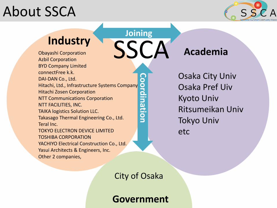
About SSCA
SSCA Obayashi Corporation Azbil Corporation BYD Company Limited connectFree k.k. DAI-DAN Co., Ltd. Hitachi, Ltd., Infrastructure Systems Company Hitachi Zosen Corporation NTT Communications Corporation NTT FACILITIES, INC. TAIKA logistics Solution LLC. Takasago Thermal Engineering Co., Ltd. Teral Inc. TOKYO ELECTRON DEVICE LIMITED TOSHIBA CORPORATION YACHIYO Electrical Construction Co., Ltd. Yasui Architects & Engineers, Inc. Other 2 companies,
City of Osaka
Osaka City Univ Osaka Pref Uiv Kyoto Univ Ritsumeikan Univ Tokyo Univ etc
Industry Academia
Government
Joining
Co
ord
inatio
n
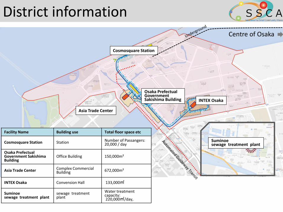
District information
Centre of Osaka
Cosmosquare Station
Asia Trade Center
Osaka Prefectual Government Sakishima Building INTEX Osaka
Suminoe sewage treatment plant
Facility Name Building use Total floor space etc
Cosmosquare Station Station Number of Passangers: 20,000 / day
Osaka Prefectual Government Sakishima Building
Office Building 150,000m²
Asia Trade Center Complex Commercial Building 672,000m²
INTEX Osaka Convension Hall 133,000㎡
Suminoe sewage treatment plant
sewage treatment plant
Water treatment capacity: 220,000㎡/day,
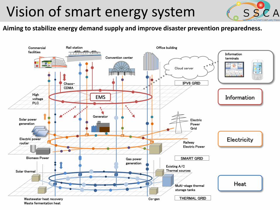
Vision of smart energy system Aiming to stabilize energy demand supply and improve disaster prevention preparedness.
Solar power generation
Biomass Power Gas power generation
Generator Electric Power Grid
Railway Electric Power
Commercial facilities
Convention center
Office building
Cloud server
Existing A/C Thermal sources
Co-gen Wastewater heat recovery Waste fermentation heat
Solar thermal
Multi-stage thermal storage tanks
High voltage PLC
Chaos- CDMA
Electric power router
IPV6 GRID
SMART GRID
THERMAL GRID
Information
Electricity
Heat
EMS
Information terminals
Rail station
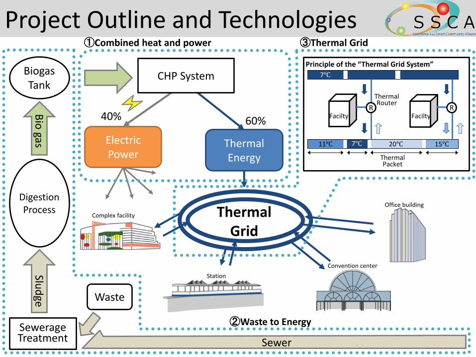
Project Outline and Technologies
Complex facility
Station
Convention center
Office building
Waste
Bio
gas
Digestion Process
Slud
ge
Biogas Tank
Electric Power
40%
Thermal Energy
60%
Thermal Grid
R
Thermal Router
R Facilty Facilty
7℃
11℃ 7℃ 20℃ 15℃
Thermal Packet
Principle of the “Thermal Grid System”
CHP System
①Combined heat and power
Sewerage Treatment Sewer
②Waste to Energy
③Thermal Grid
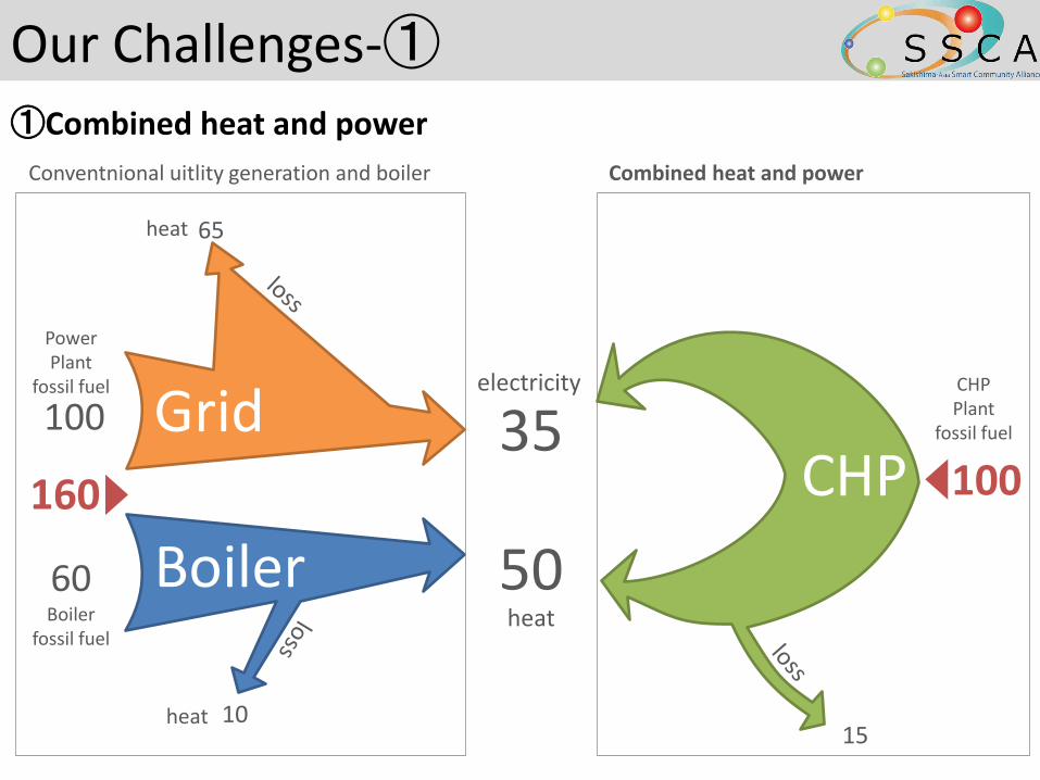
Our Challenges-①
①Combined heat and power
electricity
heat
50
35 Grid
Boiler
heat 65
Power Plant
fossil fuel
100
Boiler fossil fuel
60
heat 10
CHP
Conventnional uitlity generation and boiler Combined heat and power
160 100
CHP Plant
fossil fuel
15
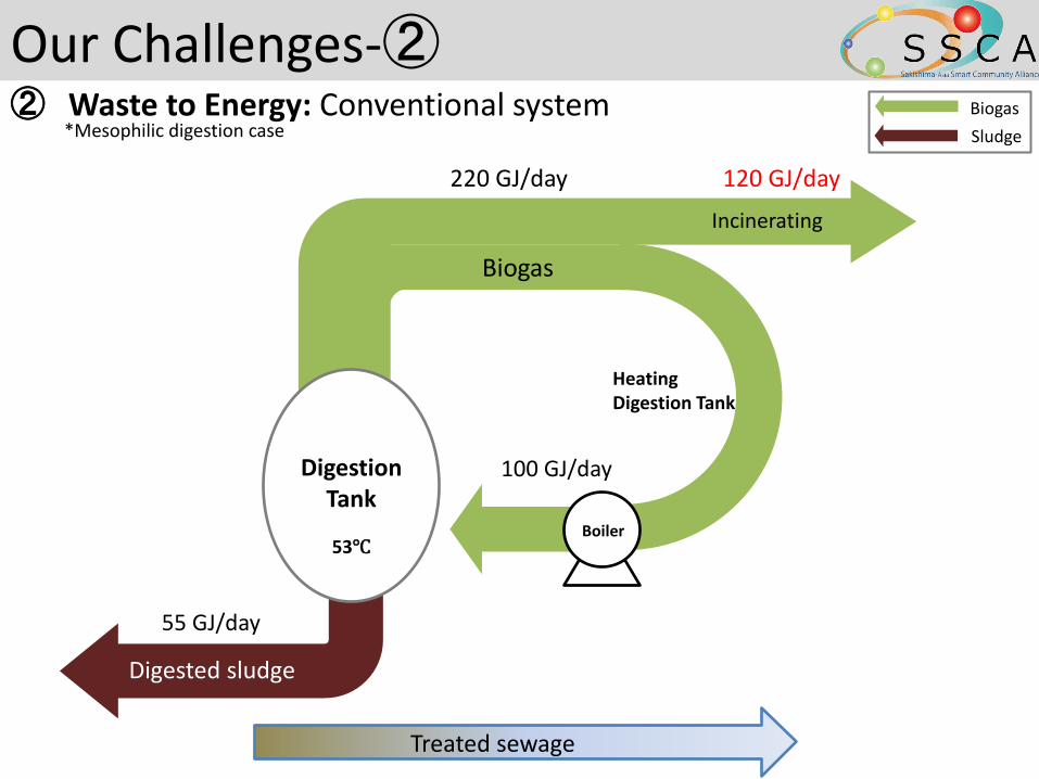
Our Challenges-② ② Waste to Energy: Conventional system
Treated sewage
100 GJ/day
55 GJ/day
220 GJ/day
Biogas
Sludge
Biogas
53℃
Digestion Tank
Digested sludge
Boiler
Incinerating
120 GJ/day
Heating Digestion Tank
*Mesophilic digestion case
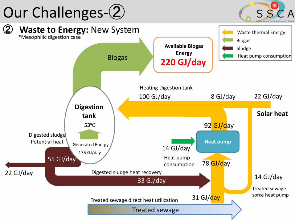
Our Challenges-②
Heat pump
Treated sewage sorce heat pump
14 GJ/day
8 GJ/day
92 GJ/day
100 GJ/day
55 GJ/day
53℃
22 GJ/day
14 GJ/day
22 GJ/day
Solar heat
Generated Energy
Waste thermal Energy
Biogas
Sludge
Heat pump consumption
31 GJ/day
175 GJ/day
Heating Digestion tank
Digested sludge Potential heat
Treated sewage
Treated sewage direct heat utilization
Heat pump consumption
Biogas
Digestion tank
33 GJ/day
78 GJ/day Digested sludge heat recovery
220 GJ/day
Available Biogas Energy
② Waste to Energy: New System
*Mesophilic digestion case

Features 1. To connect buildings (chillers and loads) via loop pipes. 2. To bring diversity effect into real energy conservation
operation 3. To realize chilled water cascade use or serial use,
which require flow route changer, and which allow large temperature difference operation
4. To select chillers to be operated from a number of chillers in buildings in optimum manner
5. To plan variable chilled water temperature operation
Our Challenge-③
③Thermal Grid
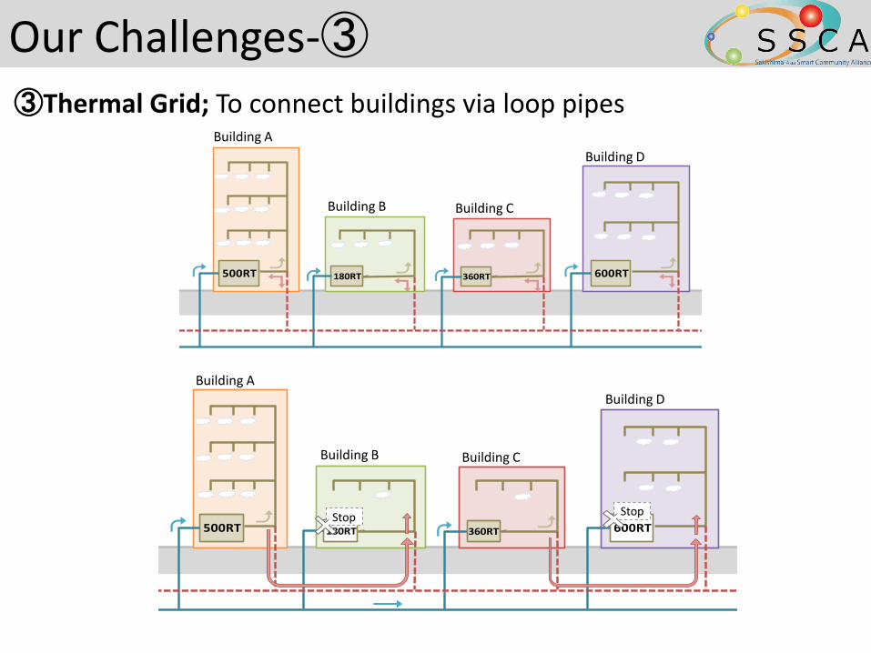
Our Challenges-③
③Thermal Grid; To connect buildings via loop pipes 施設A
施設B
施設D
施設C
500RT 180RT 360RT 600RT
500RT 180RT 360RT 600RT停止
停止
施設A
施設B
施設D
施設C
Building A
Building B Building C
Building D
Building A
Building B Building C
Building D
Stop Stop
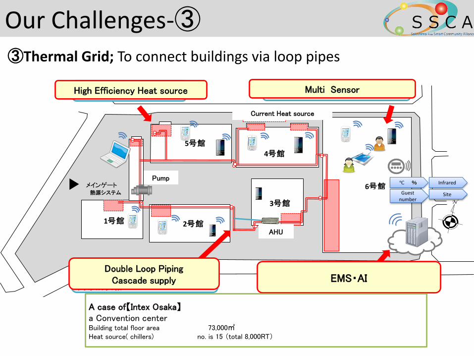
Our Challenges-③
③Thermal Grid; To connect buildings via loop pipes
3号館
2号館1号館
4号館
5号館
6号館メインゲート
新設熱源
既設熱源
④負荷要求に応じて温度別に冷温水を搬送し最少エネルギーで空調を可能とするエネルギーマネジメントシステム
②冷温水の自在なカスケード利用による異なる冷温水温度のゾーン・時間帯別供給
①大温度差による熱源の高効率運転時間の最大化
③ICTを利用した、室利用者が参加できるクラウド型空調温度設定
空調機
分散ポンプ
Guest number
Site
Infrared ℃ %
熱源システム
High Efficiency Heat source
EMS・AI
Multi Sensor
Double Loop Piping Cascade supply
Current Heat source
Pump
AHU
A case of【Intex Osaka】
a Convention center Building total floor area 73,000㎡ Heat source( chillers) no. is 15 (total 8,000RT)
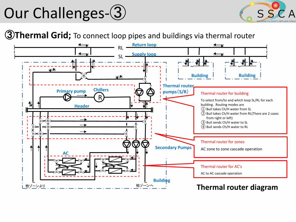
RL
SL
R
z
~
Thermal router for building
To select from/to and which loop SL/RL for each building. Routing modes are ① Buil takes Ch/H water from SL ② Buil takes Ch/H water from RL(There are 2 cases
from right or left) ③ Buil sends Ch/H water to SL ④ Buil sends Ch/H water to RL
Thermal router for zones
AC zone to zone cascade operation
Thermal router for AC's
AC to AC cascade operation
~
~
~
Return loop
Supply loop
Building Building
Building
AC
Header
Primary pump Chillers
他ゾーンより 他ゾーンへ
Thermal router pumps(S/R)
Secondary Pumps
z
Thermal router diagram
~ ~
Our Challenges-③ ③Thermal Grid; To connect loop pipes and buildings via thermal router
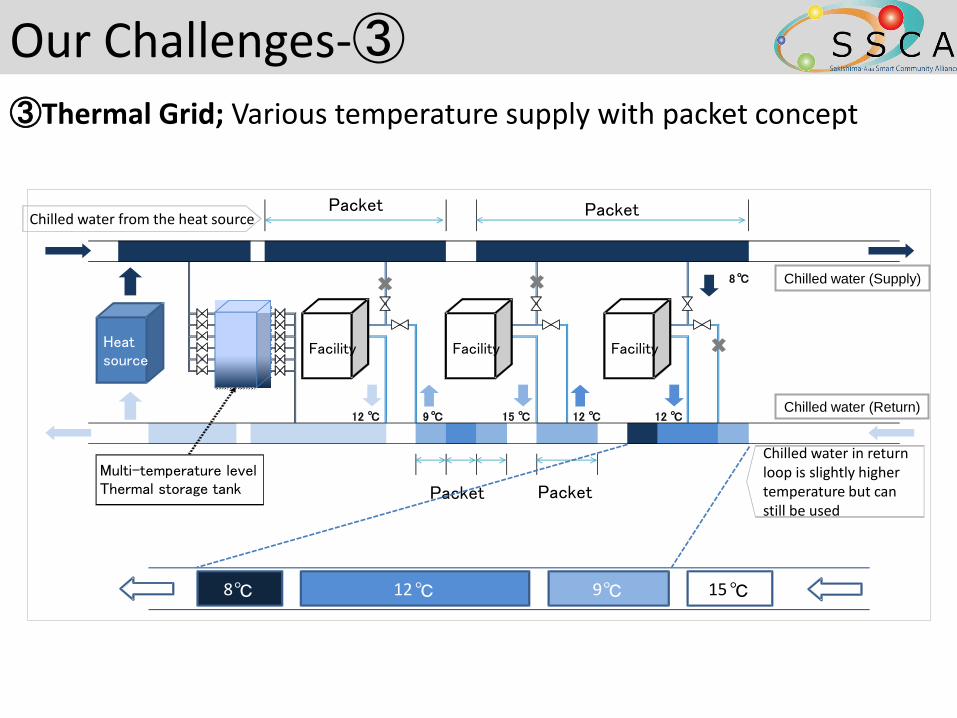
Our Challenges-③
Heat source
Facility Facility Facility
Chilled water (Supply)
12 ℃ 9 ℃ 15 ℃ 12 ℃ 12 ℃
8 ℃
Multi-temperature level Thermal storage tank Packet
8 ℃ 12 ℃ 9 ℃ 15 ℃
Chilled water in return loop is slightly higher temperature but can still be used
Chilled water from the heat source
Packet
Packet Packet
Chilled water (Return)
③Thermal Grid; Various temperature supply with packet concept

CO2 emission reduction effect
per year
10,000 t-CO2eq
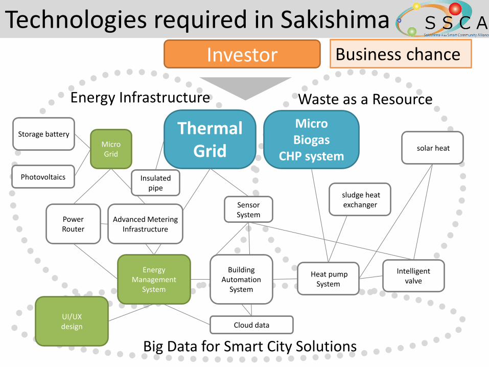
Technologies required in Sakishima
Energy Infrastructure Waste as a Resource
Big Data for Smart City Solutions
Energy Management
System
Thermal Grid
Micro Biogas
CHP system
Power Router
Micro Grid
Photovoltaics
Storage battery
Advanced Metering Infrastructure
solar heat
Heat pump System
UI/UX design Cloud data
sludge heat exchanger
Intelligent valve
Insulated pipe
Sensor System
Building Automation
System
Investor Business chance
Thank you for your kind Attention! Sakishima Asia Smart Community Alliance
sakishima-smart.jp
18


![Panasonic Reports Fiscal 2019 Annual Results Osaka, Japan ... · Osaka, Japan, May 9, 2019 -- Panasonic Corporation (Panasonic [TSE:6752]) today reported its consolidated financial](https://img.pdfslide.us/doc/110x75/5e16e5cf1d8b777cc455c6c3/panasonic-reports-fiscal-2019-annual-results-osaka-japan-osaka-japan-may.jpg)