Embed Size (px)
Citation preview
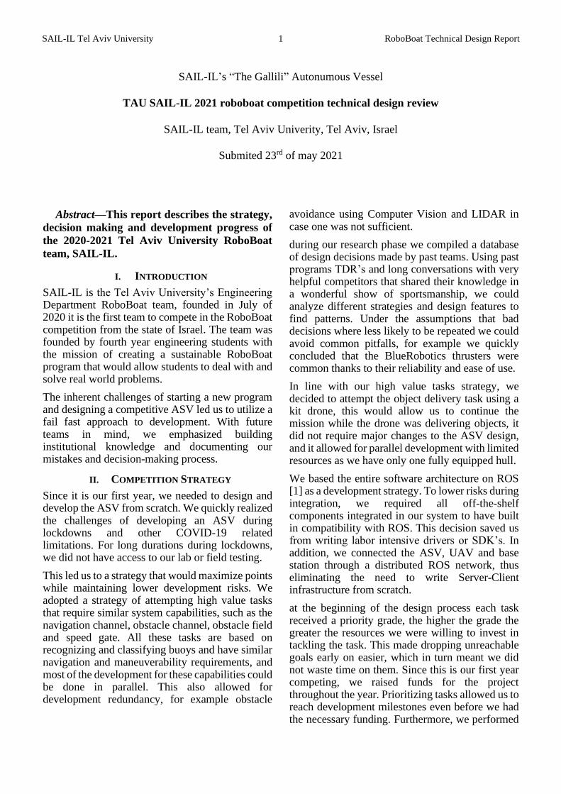
SAIL-IL Tel Aviv University 1 RoboBoat Technical Design Report
SAIL-IL’s “The Gallili” Autonumous Vessel
TAU SAIL-IL 2021 roboboat competition technical design review
SAIL-IL team, Tel Aviv Univerity, Tel Aviv, Israel
Submited 23rd of may 2021
Abstract—This report describes the strategy,
decision making and development progress of
the 2020-2021 Tel Aviv University RoboBoat
team, SAIL-IL.
I. INTRODUCTION
SAIL-IL is the Tel Aviv University’s Engineering Department RoboBoat team, founded in July of 2020 it is the first team to compete in the RoboBoat competition from the state of Israel. The team was founded by fourth year engineering students with the mission of creating a sustainable RoboBoat program that would allow students to deal with and solve real world problems.
The inherent challenges of starting a new program and designing a competitive ASV led us to utilize a fail fast approach to development. With future teams in mind, we emphasized building institutional knowledge and documenting our mistakes and decision-making process.
II. COMPETITION STRATEGY
Since it is our first year, we needed to design and develop the ASV from scratch. We quickly realized the challenges of developing an ASV during lockdowns and other COVID-19 related limitations. For long durations during lockdowns, we did not have access to our lab or field testing.
This led us to a strategy that would maximize points while maintaining lower development risks. We adopted a strategy of attempting high value tasks that require similar system capabilities, such as the navigation channel, obstacle channel, obstacle field and speed gate. All these tasks are based on recognizing and classifying buoys and have similar navigation and maneuverability requirements, and most of the development for these capabilities could be done in parallel. This also allowed for development redundancy, for example obstacle
avoidance using Computer Vision and LIDAR in case one was not sufficient.
during our research phase we compiled a database of design decisions made by past teams. Using past programs TDR’s and long conversations with very helpful competitors that shared their knowledge in a wonderful show of sportsmanship, we could analyze different strategies and design features to find patterns. Under the assumptions that bad decisions where less likely to be repeated we could avoid common pitfalls, for example we quickly concluded that the BlueRobotics thrusters were common thanks to their reliability and ease of use.
In line with our high value tasks strategy, we decided to attempt the object delivery task using a kit drone, this would allow us to continue the mission while the drone was delivering objects, it did not require major changes to the ASV design, and it allowed for parallel development with limited resources as we have only one fully equipped hull.
We based the entire software architecture on ROS [1] as a development strategy. To lower risks during integration, we required all off-the-shelf components integrated in our system to have built in compatibility with ROS. This decision saved us from writing labor intensive drivers or SDK’s. In addition, we connected the ASV, UAV and base station through a distributed ROS network, thus eliminating the need to write Server-Client infrastructure from scratch.
at the beginning of the design process each task received a priority grade, the higher the grade the greater the resources we were willing to invest in tackling the task. This made dropping unreachable goals early on easier, which in turn meant we did not waste time on them. Since this is our first year competing, we raised funds for the project throughout the year. Prioritizing tasks allowed us to reach development milestones even before we had the necessary funding. Furthermore, we performed
SAIL-IL Tel Aviv University 2 RoboBoat Technical Design Report
a cost benefit analysis on each design component to best utilize our limited budget. For example, the decision to use a GPS-RTK system as opposed to an GNSS aided INS (like the VectorNav VN-300 utilized by other teams) was aided by the cost analysis. We realized that similar performance could be achieved since the ASV is always in range of the base station and relatively slow moving.
The following subsections are in the order of task priority. Early in the design process we decided not to attempt the acoustic docking task as it would require a niche subsystem that did not fit our strategy.
A. Navigation Channel
To demonstrate basic autonomous capabilities, the
navigation task is mandatory and must be
completed first, before any other tasks can be
attempted. The ASV needs to reach a GPS start
location that is given in advance, and pass through
the two gates 6-10 ft wide. The navigation channel
task is a development milestone, in order to achieve
the capabilities needed to complete the task we
implemented a method of continues integration and
testing. After the end of the third COVID-19
lockdown we tested new integrated features each
week on the water, this meant we could identify and
debug problems quickly.
B. Obstacle Channel
The obstacle channel requires the ASV to identify
the next gate and update the current path so that it
passes through said gate. In contrast with the
navigation channel, the path through the obstacle
channel would not be linear and the greatest risk
would be to hit a buoy. We decided to prioritize
maneuverability and platform stability over speed,
this led to the catamaran design with azimuth stern
thrusters described in the Design Creativity
section.
C. Obstacle Field
The purpose of this task is to test the ASV complex
path planning and maneuverability. The ASV
needs to track the pill buoy ant the center of
obstacle field and locate a path between the
obstacles to reach the pill buoy, circumnavigate it
and exit the obstacle field. In order to always keep
visual contact with the pill buoy and track the
obstacles surrounding the ASV, the ASV is
equipped with two ZED2 stereo vision cameras set
60° off center, each camera has a FOV of 120° so
together the vision system has an FOV of 240°. The
full obstacle acquisition and mapping system is
described in the design creativity section.
D. Object Delivery
we decided to use a UAV as the object delivery
system as it would allow the ASV to continue its
mission simultaneously to the UAV. Since we only
had funding and time to build one fully equipped
ASV the sub teams needed to coordinate work on a
limited resource. Using the UAV ment we could
develop its capabilities in parallel to the ASV
development until the integration stage.
To promise easier integration with the ASV and
base station we decided to use a drone that could
connect to the ROS network over Wi-Fi. We could
not find a commercial, ready-to-fly drone within
the required specifications, so we built a kit drone
and added an onboard Jetson Nano that could
control the autopilot and communicate with the
ROS network.
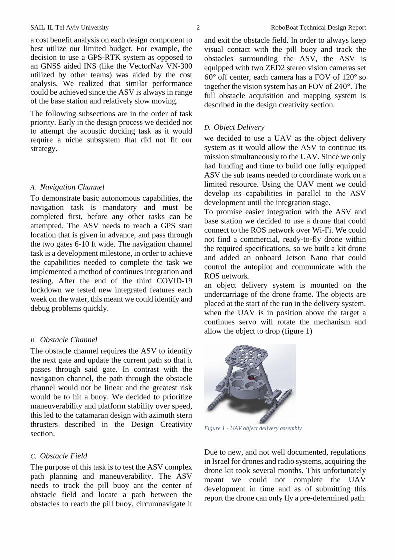
an object delivery system is mounted on the
undercarriage of the drone frame. The objects are
placed at the start of the run in the delivery system.
when the UAV is in position above the target a
continues servo will rotate the mechanism and
allow the object to drop (figure 1)
Figure 1 - UAV object delivery assembly
Due to new, and not well documented, regulations
in Israel for drones and radio systems, acquiring the
drone kit took several months. This unfortunately
meant we could not complete the UAV
development in time and as of submitting this
report the drone can only fly a pre-determined path.
SAIL-IL Tel Aviv University 3 RoboBoat Technical Design Report
III. DESIGN CREATIVITY
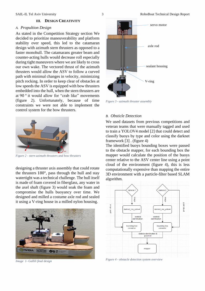
A. Propultion Design
As stated in the Competition Strategy section We
decided to prioritize maneuverability and platform
stability over speed, this led to the catamaran
design with azimuth stern thrusters as opposed to a
faster monohull. The catamarans greater beam and
counter-acting hulls would decrease roll especially
during tight maneuvers where we are likely to cross
our own wake. The vectored thrust of the azimuth
thrusters would allow the ASV to follow a curved
path with minimal changes in velocity, minimizing
pitch rocking. In order to keep clear of obstacles at
low speeds the ASV is equipped with bow thrusters
embedded into the hull, when the stern thrusters are
at 90 ° it would allow for “crab like” movements
(figure 2). Unfortunately, because of time
constraints we were not able to implement the
control system for the bow thrusters.
Figure 2 - stern azimuth thrusters and bow thrusters
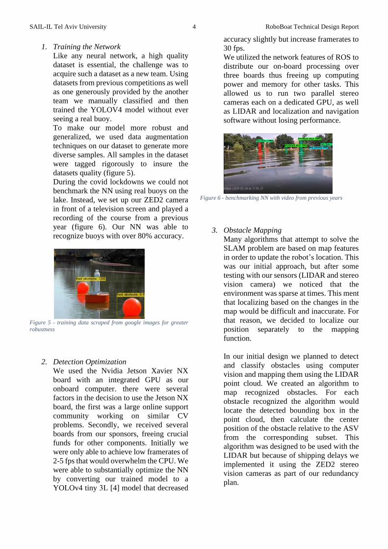
designing a thruster axis assembly that could rotate
the thrusters 180°, pass through the hull and stay
watertight was a technical challenge. The hull itself
is made of foam covered in fiberglass, any water in
the axel shaft (figure 3) would soak the foam and
compromise the hulls buoyancy over time. We
designed and milled a costume axle rod and sealed
it using a V-ring house in a milled nylon housing.
Image 1- Gallili final design
Figure 3 - azimuth thruster assembly
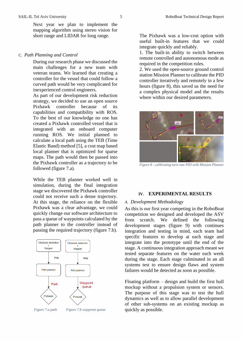
B. Obsticle Detection
We used datasets from previous competitions and
veteran teams that were manually tagged and used
to train a YOLOV4 model [2] that could detect and
classify buoys by type and color using the darknet
framework [3] . (figure 4)
The identified buoys bounding boxes were passed
to the obstacle mapper, for each bounding box the
mapper would calculate the position of the buoys
center relative to the ASV center line using a point
cloud of the environment (figure 4), this is less
computationally expensive than mapping the entire
3D environment with a particle-filter based SLAM
algorithm.
Figure 4 - obstacle detection system overview
servo motor
axle rod
sealant housing
V-ring
SAIL-IL Tel Aviv University 4 RoboBoat Technical Design Report
1. Training the Network
Like any neural network, a high quality
dataset is essential, the challenge was to
acquire such a dataset as a new team. Using
datasets from previous competitions as well
as one generously provided by the another
team we manually classified and then
trained the YOLOV4 model without ever
seeing a real buoy.
To make our model more robust and
generalized, we used data augmentation
techniques on our dataset to generate more
diverse samples. All samples in the dataset
were tagged rigorously to insure the
datasets quality (figure 5).
During the covid lockdowns we could not
benchmark the NN using real buoys on the
lake. Instead, we set up our ZED2 camera
in front of a television screen and played a
recording of the course from a previous
year (figure 6). Our NN was able to
recognize buoys with over 80% accuracy.
Figure 5 - training data scraped from google images for greater
robustness
2. Detection Optimization
We used the Nvidia Jetson Xavier NX
board with an integrated GPU as our
onboard computer. there were several
factors in the decision to use the Jetson NX
board, the first was a large online support
community working on similar CV
problems. Secondly, we received several
boards from our sponsors, freeing crucial
funds for other components. Initially we
were only able to achieve low framerates of
2-5 fps that would overwhelm the CPU. We
were able to substantially optimize the NN
by converting our trained model to a
YOLOv4 tiny 3L [4] model that decreased
accuracy slightly but increase framerates to
30 fps.
We utilized the network features of ROS to
distribute our on-board processing over
three boards thus freeing up computing
power and memory for other tasks. This
allowed us to run two parallel stereo
cameras each on a dedicated GPU, as well
as LIDAR and localization and navigation
software without losing performance.
Figure 6 - benchmarking NN with video from previous years
3. Obstacle Mapping
Many algorithms that attempt to solve the
SLAM problem are based on map features
in order to update the robot’s location. This
was our initial approach, but after some
testing with our sensors (LIDAR and stereo
vision camera) we noticed that the
environment was sparse at times. This ment
that localizing based on the changes in the
map would be difficult and inaccurate. For
that reason, we decided to localize our
position separately to the mapping
function.
In our initial design we planned to detect
and classify obstacles using computer
vision and mapping them using the LIDAR
point cloud. We created an algorithm to
map recognized obstacles. For each
obstacle recognized the algorithm would
locate the detected bounding box in the
point cloud, then calculate the center
position of the obstacle relative to the ASV
from the corresponding subset. This
algorithm was designed to be used with the
LIDAR but because of shipping delays we
implemented it using the ZED2 stereo
vision cameras as part of our redundancy
plan.
SAIL-IL Tel Aviv University 5 RoboBoat Technical Design Report
Next year we plan to implement the
mapping algorithm using stereo vision for
short range and LIDAR for long range.
C. Path Planning and Control
During our research phase we discussed the
main challenges for a new team with
veteran teams. We learned that creating a
controller for the vessel that could follow a
curved path would be very complicated for
inexperienced control engineers.
As part of our development risk reduction
strategy, we decided to use an open source
Pixhawk controller because of its
capabilities and compatibility with ROS.
To the best of our knowledge no one has
created a Pixhawk controlled vessel that is
integrated with an onboard computer
running ROS. We initial planned to
calculate a local path using the TEB (Time
Elastic Band) method [5], a cost map based
local planner that is optimized for sparse
maps. The path would then be passed into
the Pixhawk controller as a trajectory to be
followed (figure 7.a).
While the TEB planner worked well in
simulation, during the final integration
stage we discovered the Pixhawk controller
could not receive such a dense trajectory.
At this stage, the reliance on the flexible
Pixhawk was a clear advantage, we could
quickly change our software architecture to
pass a queue of waypoints calculated by the
path planner to the controller instead of
passing the required trajectory (figure 7.b).
Figure 7.a path Figure 7.b waypoint queue
The Pixhawk was a low-cost option with
useful built-in features that we could
integrate quickly and reliably.
1. The built-in ability to switch between
remote controlled and autonomous mode as
required in the competition rules.
2. We used the open-source ground control
station Mission Planner to calibrate the PID
controller iteratively and remotely in a few
hours (figure 8), this saved us the need for
a complex physical model and the results
where within our desired parameters.
Figure 8 - calibrating turn rate PID with Mission Planner
IV. EXPERIMENTAL RESULTS
A. Development Methodology
As this is our first year competing in the RoboBoat
competition we designed and developed the ASV
from scratch. We defined the following
development stages (figure 9) with continues
integration and testing in mind, each team had
specific features to develop at each stage and
integrate into the prototype until the end of the
stage. A continuous integration approach meant we
tested separate features on the water each week
during the stage. Each stage culminated in an all
systems test to ensure design flaws and system
failures would be detected as soon as possible.
Floating platform – design and build the first hull
mockup without a propulsion system or sensors.
The purpose of this stage was to test the hull
dynamics as well as to allow parallel development
of other sub-systems on an existing mockup as
quickly as possible.

SAIL-IL Tel Aviv University 6 RoboBoat Technical Design Report
Controlled – integrate the propulsion and power
systems and remote control the vessel.
Obstacle avoiding – the vessel can sail to a
predefined waypoint and can detect and avoid an
obstacle in its path.
Situational awareness and path planning – the ASV
can map obstacles at a radius of 24ft and plan path
to the next global waypoint.
Full autonomy – implement the full state machine
that will switch the ASV modes between missions
and handle a complete course run.
As a result of COVID-19 restrictions we decided to
merge the floating platform stage with the
controlled stage, and since the first prototype
excided our maneuverability requirements, we
continued with our initial hull design.
Figure 9 - development and testing stages
B. Platform and Remote Control Tests
Due to COVID-19 our first test sailing the bare
prototype in water was on the 7th of January 2021,
we tested the vessels maneuverability, controller
range and waterproofing (figure 10).
Figure 10 - remote control test
C. PID Callibration
using the open source and versatile Pixhawk
controller meant we could calibrate the PID
controller within a few hours using the compatible
ground control station GUI (figure 8). After
calibrating the PID we tested the ASV’s ability to
follow a dense path of waypoints. The results
excided specifications (figure 11)
Figure 11 - path with dense waypoints
D. Object Detection and Mapping
after testing the neural network’s ability to detect
and classify buoys, we tested the obstacle mapping
algorithm in different environments, the buoy is
classified by the NN, the bounding box of the
object is the passed to the mapping algorithm
which calculates the relative position of the buoy
and sends it to the path planner (figure 12)
Figure 12 - testing object mapping algorithm
E. Testing the LIDAR
the initial ASV design included a 16-channel 3D
LIDAR (Velodyne VLP-16) but due to lack of
SAIL-IL Tel Aviv University 7 RoboBoat Technical Design Report
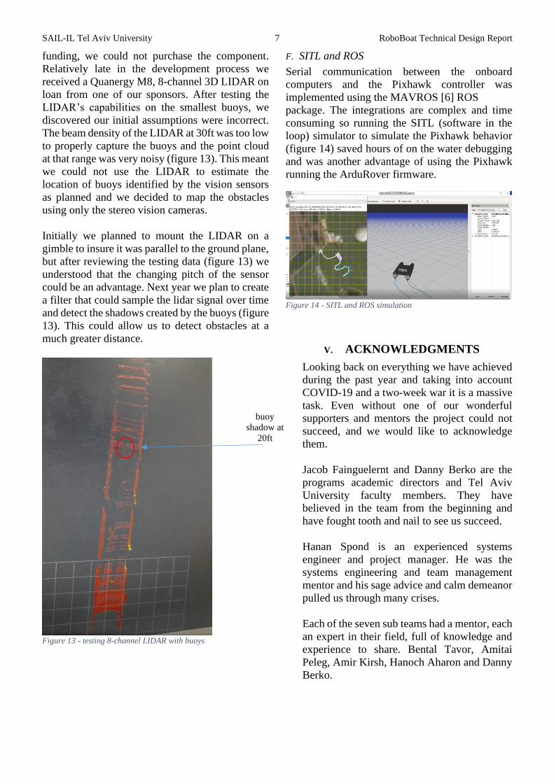
funding, we could not purchase the component.
Relatively late in the development process we
received a Quanergy M8, 8-channel 3D LIDAR on
loan from one of our sponsors. After testing the
LIDAR’s capabilities on the smallest buoys, we
discovered our initial assumptions were incorrect.
The beam density of the LIDAR at 30ft was too low
to properly capture the buoys and the point cloud
at that range was very noisy (figure 13). This meant
we could not use the LIDAR to estimate the
location of buoys identified by the vision sensors
as planned and we decided to map the obstacles
using only the stereo vision cameras.
Initially we planned to mount the LIDAR on a
gimble to insure it was parallel to the ground plane,
but after reviewing the testing data (figure 13) we
understood that the changing pitch of the sensor
could be an advantage. Next year we plan to create
a filter that could sample the lidar signal over time
and detect the shadows created by the buoys (figure
13). This could allow us to detect obstacles at a
much greater distance.
Figure 13 - testing 8-channel LIDAR with buoys
F. SITL and ROS
Serial communication between the onboard
computers and the Pixhawk controller was
implemented using the MAVROS [6] ROS
package. The integrations are complex and time
consuming so running the SITL (software in the
loop) simulator to simulate the Pixhawk behavior
(figure 14) saved hours of on the water debugging
and was another advantage of using the Pixhawk
running the ArduRover firmware.
Figure 14 - SITL and ROS simulation
V. ACKNOWLEDGMENTS
Looking back on everything we have achieved
during the past year and taking into account
COVID-19 and a two-week war it is a massive
task. Even without one of our wonderful
supporters and mentors the project could not
succeed, and we would like to acknowledge
them.
Jacob Fainguelernt and Danny Berko are the
programs academic directors and Tel Aviv
University faculty members. They have
believed in the team from the beginning and
have fought tooth and nail to see us succeed.
Hanan Spond is an experienced systems
engineer and project manager. He was the
systems engineering and team management
mentor and his sage advice and calm demeanor
pulled us through many crises.
Each of the seven sub teams had a mentor, each
an expert in their field, full of knowledge and
experience to share. Bental Tavor, Amitai
Peleg, Amir Kirsh, Hanoch Aharon and Danny
Berko.
buoy
shadow at
20ft
SAIL-IL Tel Aviv University 8 RoboBoat Technical Design Report
Our gracious sponsors took a chance on us
when all we had was a slideshow and funded
the program.
Barak Lafer from Israel Shipyards
• Meir Ben Tzuk, Hanan Spond and Ami
Akiva from Rafael Advanced Systems
• Tzvika Webb from Synopsis
• Nvidia
• Adar Adler form Xenom
• Moran Nir from Amazon
To each of our amazing supports, we deeply thank
you for believing in us.
VI. REFERENCES
[1
] M. . Quigley, B. . Gerkey, K. . Conley, J. . Faust, T. .
Foote, J. . Leibs, E. . Berger, R. . Wheeler and A. . Ng,
"ROS: an open-source Robot Operating System," , .
[Online]. Available:
http://www.robotics.stanford.edu/~ang/papers/icraoss0
9-ROS.pdf. [Accessed 21 5 2021].
[2
]
C.-Y. W. H.-Y. M. L. Alexey Bochkovskiy, YOLOv4:
Optimal Speed and Accuracy of Object Detection,
arXiv:2004.10934, 2020.
[3
]
A. F. Joseph Redmon, YOLOv3: An Incremental
Improvement, arXiv:1804.02767, 2018.
[4
]
L. Z. S. L. Y. J. Zicong Jiang, Real-time object
detection method based on improved YOLOv4-tiny,
arXiv:2011.04244, 2020.
[5
]
W. F. T. W. F. H. a. T. B. C. Rösmann, "Trajectory
modification considering dynamic constraints of
autonomous robots," Proc. 7th German Conference on
Robotics, Germany, Munich, pp. 74-79, 2012.
[6
]
V. Ermakov, MAVROS -- MAVLink extendable
communication node for ROS with proxy for Ground
Control Station., ROS.org, 2018.
SAIL-IL Tel Aviv University 9 RoboBoat Technical Design Report
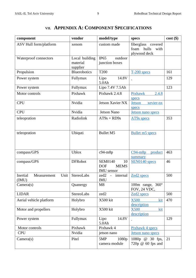
VII. APPENDIX A: COMPONENT SPECIFICATIONS
component vendor model/type specs cost ($)
ASV Hull form/platform xenom custom made fiberglass covered
foam hulls with
plywood deck
Waterproof connectors Local building
material
supplier
IP65 outdoor
junction boxes
Propulsion Bluerobotics T200 T-200 specs 161
Power system Fullymax Lipo 14.8V
5.0Ah
129
Power system Fullymax Lipo 7.4V 7.5Ah 123
Motor controls Pixhawk Pixhawk 2.4.8 Pixhawk 2.4.8
specs
CPU Nvidia Jetson Xavier NX Jetson xevier-nx
specs
CPU Nvidia Jetson Nano Jetson nano specs
teleopration Radiolink AT9s + RD9s AT9s specs 353
teleopration Ubiquti Bullet M5 Bullet m5 specs
compass/GPS Ublox c94-m8p C94-m8p product
summary
463
compass/GPS DFRobot SEM0140 10
DOF MEMS
IMU sensor
SEN0140 specs 46
Inertial Measurement Unit
(IMU)
StereoLabs zed2 - internal
IMU
Zed2 specs 500
Camera(s) Quanergy M8 100m range, 360°
FOV, 24 VDC,
LIDAR StereoLabs zed2 Zed2 specs 500
Aerial vehicle platform Holybro X500 kit X500 kit
description
470
Motor and propellers Holybro X500 kit X500 kit
description
Power system Fullymax Lipo 14.8V
5.0Ah
129
Motor controls Pixhawk Pixhawk 4 Pixhawk 4 specs
CPU Nvidia jetson nano Jetson nano specs
Camera(s) Pitel 5MP 1080p
camera module
1080p @ 30 fps,
720p @ 60 fps and
21

SAIL-IL Tel Aviv University 10 RoboBoat Technical Design Report
640*480p 60/90
video recording
Autopilot Ardupilot Ardurover boat open
source
Algorithms TEB local planer
Vision YOLOv4 and
darknet
Localization and mapping custom
Autonomy custom
Team Size (number of people) 15
Expertise ratio (hardware vs.
software)
2:3
Testing time: simulation 100+
Testing time: in-water 80+
Inter-vehicle communication ROS-network
over 5GHz
Wi-Fi
Programming Language(s) Python, ROS,
C++
SAIL-IL Tel Aviv University 11 RoboBoat Technical Design Report
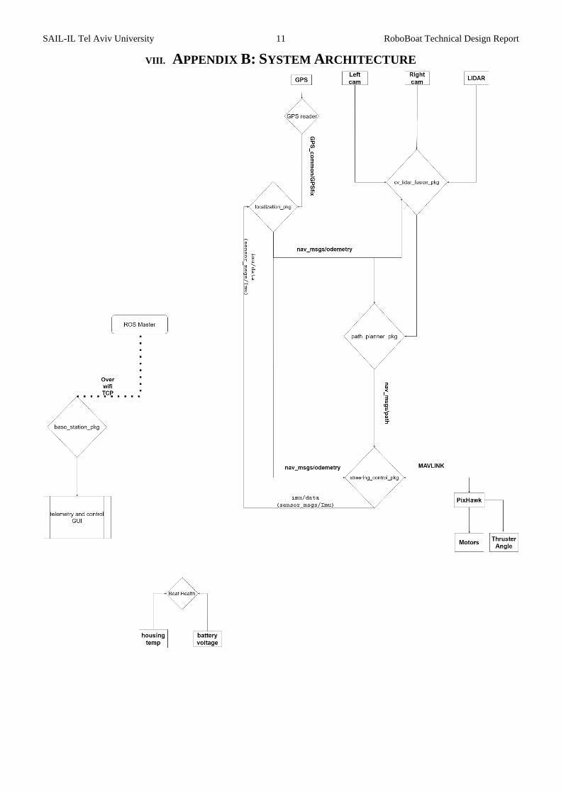
VIII. APPENDIX B: SYSTEM ARCHITECTURE
SAIL-IL Tel Aviv University 12 RoboBoat Technical Design Report
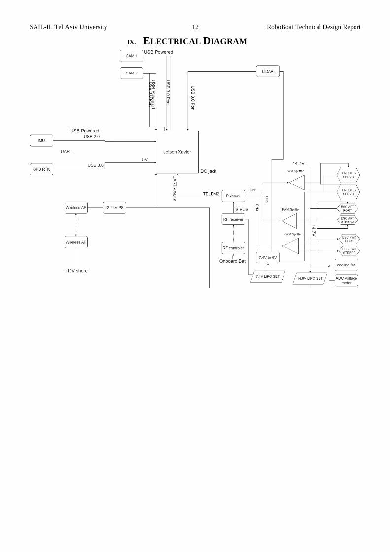
IX. ELECTRICAL DIAGRAM