Embed Size (px)
Citation preview
MAXOS®
SAfety Sight And LeveL gAuge gLASSeS SpeciAL-teMpered MAde in gerMAny
the cOMpLete SAfety Sight And LeveL gAuge gLASS prOgrAM
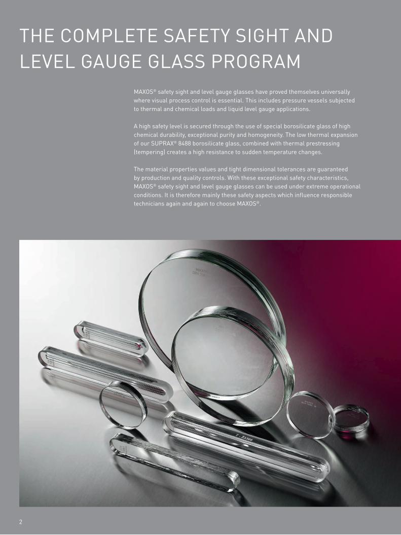
MAXOS® safety sight and level gauge glasses have proved themselves universally where visual process control is essential. this includes pressure vessels subjected to thermal and chemical loads and liquid level gauge applications.
A high safety level is secured through the use of special borosilicate glass of high chemical durability, exceptional purity and homogeneity. the low thermal expansion of our SuprAX® 8488 borosilicate glass, combined with thermal prestressing (tempering) creates a high resistance to sudden temperature changes.
the material properties values and tight dimensional tolerances are guaranteed by production and quality controls. With these exceptional safety characteristics, MAXOS® safety sight and level gauge glasses can be used under extreme operational conditions. it is therefore mainly these safety aspects which influence responsible technicians again and again to choose MAXOS®.
2
3
MAXOS® product range
Special tempered reflex and transparent level gauge glasses and disc sight glasses can be supplied in accordance to:
• din 7080/7081• BS 3463• JiS B 8211• MiL – g – 16356 d• Auer uSA specification• high pressure• customer specification• Aluminosilicate glass on request
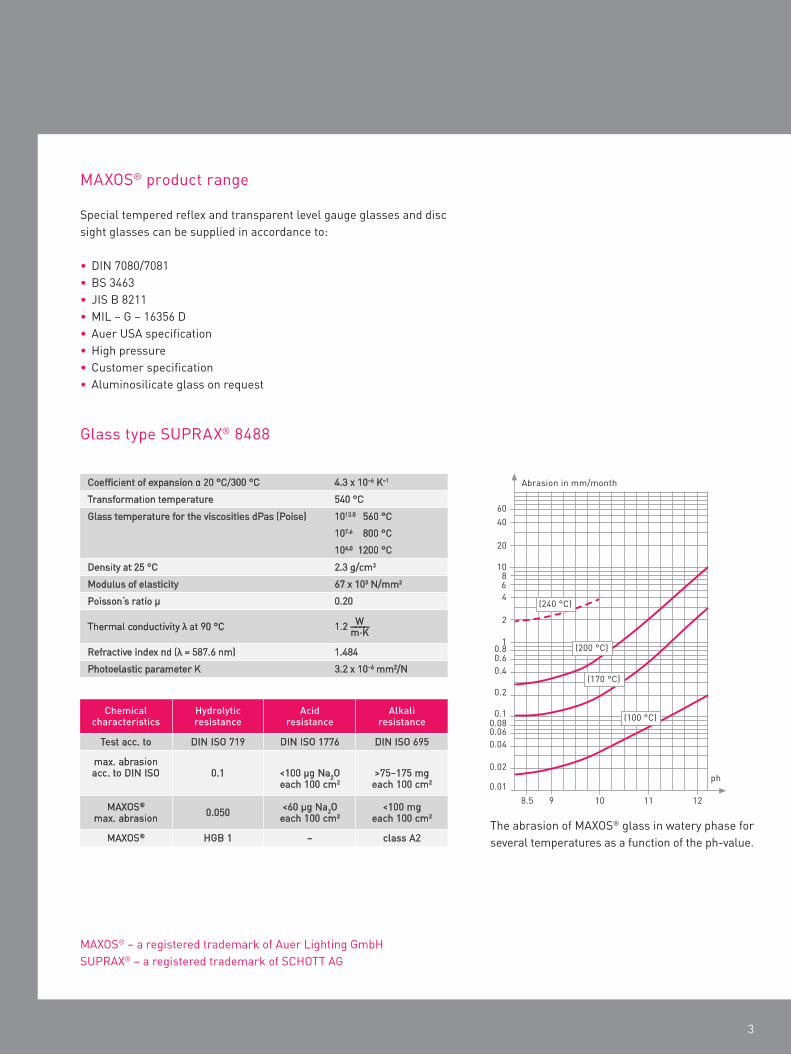
the abrasion of MAXOS® glass in watery phase for several temperatures as a function of the ph-value.
MAXOS® – a registered trademark of Auer Lighting gmbh SuprAX® – a registered trademark of SchOtt Ag
Chemicalcharacteristics
Hydrolyticresistance
Acidresistance
Alkaliresistance
test acc. to din iSO 719 din iSO 1776 din iSO 695
max. abrasion acc. to din iSO 0.1 <100 µg na2O
each 100 cm2>75–175 mg
each 100 cm2
MAXOS®
max. abrasion 0.050 <60 µg na2O each 100 cm2
<100 mgeach 100 cm2
MAXOS® hgB 1 – class A2
coefficient of expansion α 20 °c/300 °c 4.3 x 10⁻⁶ K–1
transformation temperature 540 °c
glass temperature for the viscosities dpas (poise) 1013.0 560 °c
107.6 800 °c
104.0 1200 °c
density at 25 °c 2.3 g/cm3
Modulus of elasticity 67 x 103 n/mm2
poisson‘s ratio μ 0.20
thermal conductivity λ at 90 °c 1.2
refractive index nd (λ = 587.6 nm) 1.484
photoelastic parameter K 3.2 x 10⁻⁶ mm2/n
Wm·K
glass type SuprAX® 8488
————
MAXOS® LeveL gAuge gLASSeS
4
Long form reflex and transparent
Bending strength is determined by the surface compressive stress and the inherent resistance of the glass. the inherent resistance is heavily dependent upon the surface quality. for safety reasons, the stress to the glasses caused by internal forces, thermal stress and vessel pressure have to be totally absorbed by the surface compressive stress so that a tensile stress of the glass surface is prevented.
Application conditions Maximum permissiblepressure
Maximum permissibletemperature
bar psi °C °F
Saturated steam or hot water in direct contact with reflex or transparent sight glasses
35
500
243
470
Saturated steam or hot water in contact with transparent sight glasses protected with mica
103
1,500
320
608
non-corrosive, non-steam service and no technically significant glass attack, with reflex or transparent glasses
280
4,000
38
100
transparent sight glasses in contact with medias with no technically significant glass attack
345
5,000
38
100
high pressure transparent sight glasses in special armatures (gauges)
414
6,000
38
100
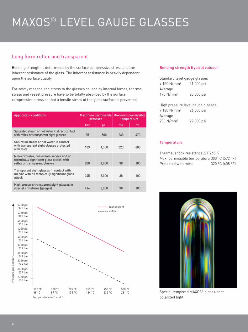
Special tempered MAXOS® glass under polarized light.
Bending strength (typical values)
Standard level gauge glasses≥ 150 n/mm2 21,000 psiAverage170 n/mm2 25,000 psi
high pressure level gauge glasses≥ 180 n/mm2 26,000 psiAverage200 n/mm2 29,000 psi
Temperature
thermal shock resistance ∆ t 265 KMax. permissible temperature 300 °c (572 °f)protected with mica 320 °c (608 °f)
5
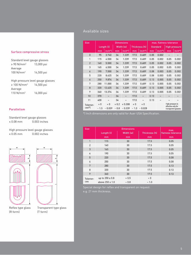
Available sizes
Size Dimensions max. flatness tolerance
Length (l) Width (w) Thickness (h) Standard High pressure
mm inch*) mm inch*) mm inch*) mm inch*) mm inch*)
0 95 3.740 34 1.339 17.5 0.689 0.05 0.002 – –
1 115 4.500 34 1.339 17.5 0.689 0.05 0.002 0.05 0.002
2 140 5.500 34 1.339 17.5 0.689 0.05 0.002 0.05 0.002
3 165 6.500 34 1.339 17.5 0.689 0.05 0.002 0.05 0.002
4 190 7.500 34 1.339 17.5 0.689 0.08 0.003 0.05 0.002
5 220 8.625 34 1.339 17.5 0.689 0.08 0.003 0.05 0.002
6 250 9.874 34 1.339 17.5 0.689 0.13 0.005 0.05 0.002
7 280 11.000 34 1.339 17.5 0.689 0.13 0.005 0.05 0.002
8 320 12.625 34 1.339 17.5 0.689 0.13 0.005 0.05 0.002
9 340 13.374 34 1.339 17.5 0.689 0.13 0.005 0.05 0.002
10 370 – 34 – 17.5 – 0.13 – – –
11 400 – 34 – 17.5 – 0.13 – – –
toleran-ces*)
+ 0 + 0 + 0.2 + 0.008 + 0 + 0 high pressure is effective only for transparent glasses.– 1.5 – 0.039 – 0.8 – 0.039 – 1.0 – 0.028
*) inch dimensions are only valid for Auer uSA Specification.
Special design for reflex and transparent on request: e.g. 21 mm thickness.
Size Dimensions max. flatness toleranceLength (l) Width (w) Thickness (h)
mm mm mm mm
1 115 30 17.5 0.05
2 140 30 17.5 0.05
3 165 30 17.5 0.05
4 190 30 17.5 0.05
5 220 30 17.5 0.08
6 250 30 17.5 0.08
7 280 30 17.5 0.13
8 320 30 17.5 0.13
9 340 30 17.5 0.13
toleran-ces
up to 250 ± 0.8 + 0.5 + 0
above 250 ± 1.0 – 0.8 – 1.0
hl
hl
ww
reflex type glass (r form)
transparent type glass (t form)
Parallelism
Standard level gauge glasses≤ 0.08 mm 0.003 inches
high pressure level gauge glasses≤ 0.05 mm 0.002 inches
Surface compressive stress
Standard level gauge glasses≥ 90 n/mm2 13,000 psiAverage100 n/mm2 14,500 psi
high pressure level gauge glasses≥ 100 n/mm2 14,500 psiAverage110 n/mm2 16,000 psi
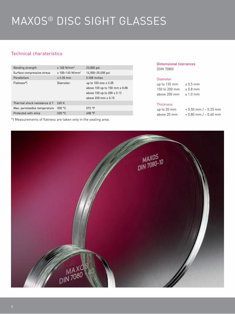
MAXOS® diSc Sight gLASSeS
6
technical charateristics
Dimensional tolerances (din 7080)
diameter up to 135 mm ± 0.5 mm150 to 200 mm ± 0.8 mmabove 200 mm ± 1.0 mm
thicknessup to 20 mm + 0.50 mm / – 0.25 mmabove 20 mm + 0.80 mm / – 0.40 mm
Bending strength ≥ 160 n/mm2 23,000 psi
Surface compressive stress ≥ 100–140 n/mm2 14,500–20,000 psi
parallelism ≤ 0.20 mm 0.008 inches
flatness*) diameter: up to 100 mm ≤ 0.05
above 100 up to 150 mm ≤ 0.08
above 150 up to 200 ≤ 0.12
above 200 mm ≤ 0.15
thermal shock resistance ∆ t 265 K
Max. permissible temperature 300 °c 572 °f
protected with mica 320 °c 608 °f
*) Measurements of flatness are taken only in the sealing area.
7
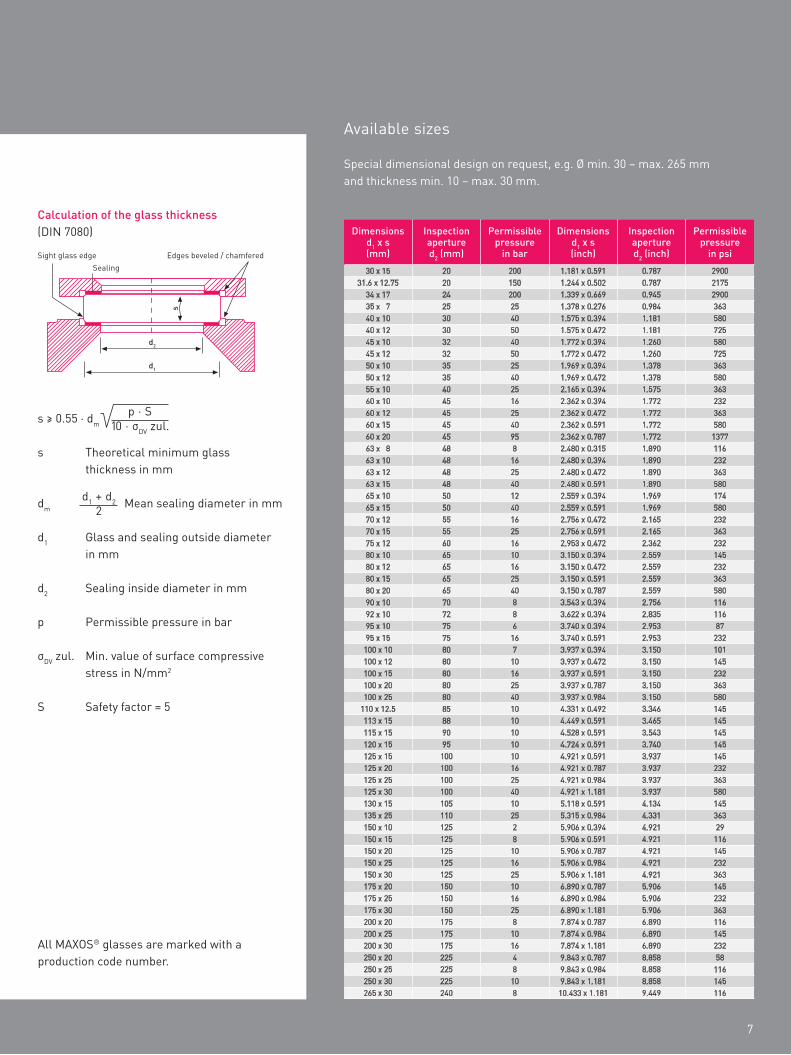
Dimensions d1 x s (mm)
Inspection aperture d2 (mm)
Permissible pressure
in bar
Dimensions d1 x s (inch)
Inspection aperture d2 (inch)
Permissible pressure
in psi
30 x 15 20 200 1.181 x 0.591 0.787 290031.6 x 12.75 20 150 1.244 x 0.502 0.787 2175
34 x 17 24 200 1.339 x 0.669 0.945 290035 x 7 25 25 1.378 x 0.276 0.984 36340 x 10 30 40 1.575 x 0.394 1.181 58040 x 12 30 50 1.575 x 0.472 1.181 72545 x 10 32 40 1.772 x 0.394 1.260 58045 x 12 32 50 1.772 x 0.472 1.260 72550 x 10 35 25 1.969 x 0.394 1.378 36350 x 12 35 40 1.969 x 0.472 1.378 58055 x 10 40 25 2.165 x 0.394 1.575 36360 x 10 45 16 2.362 x 0.394 1.772 23260 x 12 45 25 2.362 x 0.472 1.772 36360 x 15 45 40 2.362 x 0.591 1.772 58060 x 20 45 95 2.362 x 0.787 1.772 137763 x 8 48 8 2.480 x 0.315 1.890 11663 x 10 48 16 2.480 x 0.394 1.890 23263 x 12 48 25 2.480 x 0.472 1.890 36363 x 15 48 40 2.480 x 0.591 1.890 58065 x 10 50 12 2.559 x 0.394 1.969 17465 x 15 50 40 2.559 x 0.591 1.969 58070 x 12 55 16 2.756 x 0.472 2.165 23270 x 15 55 25 2.756 x 0.591 2.165 36375 x 12 60 16 2.953 x 0.472 2.362 23280 x 10 65 10 3.150 x 0.394 2.559 14580 x 12 65 16 3.150 x 0.472 2.559 23280 x 15 65 25 3.150 x 0.591 2.559 36380 x 20 65 40 3.150 x 0.787 2.559 58090 x 10 70 8 3.543 x 0.394 2.756 11692 x 10 72 8 3.622 x 0.394 2.835 11695 x 10 75 6 3.740 x 0.394 2.953 8795 x 15 75 16 3.740 x 0.591 2.953 232
100 x 10 80 7 3.937 x 0.394 3.150 101100 x 12 80 10 3.937 x 0.472 3.150 145100 x 15 80 16 3.937 x 0.591 3.150 232100 x 20 80 25 3.937 x 0.787 3.150 363100 x 25 80 40 3.937 x 0.984 3.150 580
110 x 12.5 85 10 4.331 x 0.492 3.346 145113 x 15 88 10 4.449 x 0.591 3.465 145115 x 15 90 10 4.528 x 0.591 3.543 145120 x 15 95 10 4.724 x 0.591 3.740 145125 x 15 100 10 4.921 x 0.591 3.937 145125 x 20 100 16 4.921 x 0.787 3.937 232125 x 25 100 25 4.921 x 0.984 3.937 363125 x 30 100 40 4.921 x 1.181 3.937 580130 x 15 105 10 5.118 x 0.591 4.134 145135 x 25 110 25 5.315 x 0.984 4.331 363150 x 10 125 2 5.906 x 0.394 4.921 29150 x 15 125 8 5.906 x 0.591 4.921 116150 x 20 125 10 5.906 x 0.787 4.921 145150 x 25 125 16 5.906 x 0.984 4.921 232150 x 30 125 25 5.906 x 1.181 4.921 363175 x 20 150 10 6.890 x 0.787 5.906 145175 x 25 150 16 6.890 x 0.984 5.906 232175 x 30 150 25 6.890 x 1.181 5.906 363200 x 20 175 8 7.874 x 0.787 6.890 116200 x 25 175 10 7.874 x 0.984 6.890 145200 x 30 175 16 7.874 x 1.181 6.890 232250 x 20 225 4 9.843 x 0.787 8.858 58250 x 25 225 8 9.843 x 0.984 8.858 116250 x 30 225 10 9.843 x 1.181 8.858 145265 x 30 240 8 10.433 x 1.181 9.449 116
All MAXOS® glasses are marked with a production code number.
Calculation of the glass thickness (din 7080)
Sight glass edge edges beveled / chamferedSealing
s
d2
d1
s ≥ 0.55 · dm
s theoretical minimum glass thickness in mm
dm Mean sealing diameter in mm
d1 glass and sealing outside diameter in mm
d2 Sealing inside diameter in mm
p permissible pressure in bar
σdv zul. Min. value of surface compressive stress in n/mm2
S Safety factor = 5
p · S10 · σdv zul.
d1 + d22
Dimensional tolerances (din 7080)
diameter up to 135 mm ± 0.5 mm150 to 200 mm ± 0.8 mmabove 200 mm ± 1.0 mm
thicknessup to 20 mm + 0.50 mm / – 0.25 mmabove 20 mm + 0.80 mm / – 0.40 mm
Special dimensional design on request, e.g. Ø min. 30 – max. 265 mm and thickness min. 10 – max. 30 mm.
Available sizes
Auer Lighting GmbHhildesheimer Strasse 3537581 Bad gandersheimgermanyt +49 (0) 5382 701 · 137f +49 (0) 5382 701 · [email protected] P
R A
LV-3
010
_06E
111
1 0.
7 dp
/dp
Pri
nted
in G
erm
any


![The ultrametric tree of states in spin glasses: perturbative …€¦ · Andrea Lucarelli – The ultrametric tree of states in spin glasses H A [{g}] = ∫dxTr(A µ g(x))2 gauge](https://img.pdfslide.us/doc/110x75/6063ec88990cbb2c4d7c95e0/the-ultrametric-tree-of-states-in-spin-glasses-perturbative-andrea-lucarelli-a.jpg)