Embed Size (px)
Citation preview

The-Safety-Valve.com
Safety Relief Valves
Series 437
Series 459
CompactPerformanceCompactPerformance
CATALOG

2
No
No
No
No
No
Critical Service
Clean Service
BestAvailability
Med
ium
-co
ntro
lled
High operating to set pressure ratio, high backpressure
or low total height?
Clean Service application?
Critical Service / highly corrosive application?
API specified application?
Additional components beyond safety valves
Steam, gas and liquid application with low capacity in relation
to valve size?
High Performance
API
Compact Performance
ModulateAction
HighEfficiency
Orifice ≥ F
Yes
Yes
Yes
Yes
Yes
Yes
Orifice ≤ F
Required Orifice letter?
Cha
nge-
over
val
ve
Bur
stin
g di
sc
Spr
ing
load
ed
Saf
ety
Rel
ief V
alve
s
Valve Finder
How to find the right Product Group

3
Ge
ne
ral
Type 437
Packed knob H4 Long version
Type 437
Pull button H3Type 459
Cap H2Type 459
Cap H2 Balanced bellows design
Type 459
Plain lever H3
Compact Performance
General information 4
Type 439 27
Designs 28
Materials 29
Article numbers 30
Dimensions and weights
• Threaded connections 31
• Flanged connections 33
Pressure / temperature ratings 35
Approvals 36
Type 437 7
Designs 8
Materials 9
Article numbers 10
Dimensions and weights
• Threaded connections 11
• Flanged connections 13
Pressure / temperature ratings 15
Approvals 16
Type 438 17
Designs 18
Materials 19
Article numbers 20
Dimensions and weights
• Threaded connections 21
• Flanged connections 23
Pressure / temperature ratings 25
Approvals 26
Type 462 HDD 73
Designs 74
Materials 75
Article numbers 76
Dimensions and weights
• Threaded connections 77
• Flanged connections 79
Pressure / temperature ratings 81
Approvals 82
Type 459 HDD 52
Designs 53
Materials 54
Article numbers 55
Dimensions and weights
• Threaded connections 56
• Flanged connections 58
Pressure / temperature ratings 60
Approvals 61
Type 459 41
Designs 42
Materials 43
Article numbers 44
Dimensions and weights
• Threaded connections 45
• Flanged connections 47
Pressure / temperature ratings 49
Approvals 51
Type 462 62
Designs 63
Materials 64
Article numbers 65
Dimensions and weights
• Threaded connections 66
• Flanged connections 68
Pressure / temperature ratings 70
Approvals 72
Type 437
Packed knob H4
Contents
Series 437 37
Available options 37
Available connections
• Threaded connections 38
• Flanged connections 39
Series 459 83
Available options 83
Available connections
• Threaded connections 84
• Flanged connections 85
LESER Original Spare Parts Kits 86

44
Ge
ne
ral
UV
The Compact Performance product group stands for
compact dimensions with high capacity relativegreat variety of threaded and flanged connections wide pressure range
LESER Compact Performance Safety Valves
• are designed to meet all industrial applications up to F ori-fice
• open rapidly with an overpressure of max. 5 % (Series 459) resp. 10 % (Series 437) to the full design lift
• have a maximum blowdown of minus 10 % for steam/gasservice and minus 20 % for liquid service
• are developed in a close cooperation with plant engineers and service specialists
• serve for protection of processes and equipment• are approved by all important approval organisations
worldwide which ensures the worldwide applicability, for example:
• European Community: CE-marking according to the Pressure Equipment Directive (PED) 2014/68/EU and EN ISO 4126-1
• USA: UV-stamp according to ASME Section VIII Division 1, National Board certified capacities
• Germany: VdTÜV approval according to PED,EN ISO 4126-1, TÜV SV 100 and AD 2000-Merkblatt A2
• Canada: Canadian Registration Number accordingto the requirements of particular provinces
• China: AQSIQ based on the approval according toASME Section VIII Division 1 and AD 2000-Merkblatt A2
• Eurasian Custom Union: Approval acc. to EurasianCustom Union (EAC - Eurasian Conformity)
Furthermore, all LESER Compact Performance Safety Valves are designed, marked, produced and approved according to the requirements of the following regulations (directives, codes, rules and standards): EN ISO 4126-7, EN 12266-1/-2, EN 1092 Part I and II flang-ing, ASME PTC 25, ASME-Code Sec. II, ASME B 16.34, ASME B16.5 flanging, API Std. 527, API RP 576,AD 2000-Merkblatt A4, AD 2000-Merkblatt HP0.
General Information

5
Ge
ne
ral
Applications
LESER Compact Performance Safety Valves offer ultimate protection against unallowable overpressures in all applica-tions for steam, gases and liquids where smaller capacities are required.
Typical applications for LESER Compact PerformanceSafety Valves are:
• air/gas compressors and pumps• technical gases and CO2 plants• cylinder filling stations• chemical equipment and piping• pressure vessels and piping systems containing gas, air, liquid or steam • LPG / LNG terminals, carriers etc.• cryogenic systems and oxygen applications• thermal relief• high pressure extraction plants
General Design Features
LESER Compact Performance Safety Valves cover a large variety of types, materials and options to fit any application:
• connection sizes from 3/8" to 1 1/2" and 5 orifices(D through F) provide high suitability to the application
• Threaded connections, male and female, according to all international standards guarantee worldwide applicability
• Flanged connections according ANSI, DIN and JIS guarantee a worldwide applicability
• Inlet pressure ratings up to PN 850 to fit all required design pressures
• 2 standard based / inlet body materials, Chrome steel and stainless steel as well as 3 standard body materials, ductile iron, steel and stainless steel can be selected according to the application
• All parts can be machined from bar materials to cover special material requirements such as Hastelloy®, Duplex, Super Duplex, Tantalum or Titanium within unrivalled lead time
• Set pressures from 0.1 to 850 bar / 1.5 to 12325 psig make Compact Performance safety valves suitable for all industrial processes
• Operating temperatures from -273 °C bis +450 °C / -454 °F to 1022 °F (acc. to DIN EN) cover a wide range of applica-tions
• LESER Nanotightness as standard for metal-to-metal seal-ings. The nanotightness exceeds the requirements for func-tional tightness of API 527 by 50% which means e.g. less pollution when discharge to atmosphere, 50% reduction in medium loss and increased plant efficiency
• One design and spring (single trim) for steam, gas andliquid applications reduces the number of spare partsand ensures low cost maintenance management
• Ringless design needs no trim adjustments for easymaintenance
• One-piece spindle reduces friction which leads to high operation accuracy
• Self-draining body design, avoids residues and reduces corrosion
Options
• Special connections specified by the customer foroptimised adaptation to the plant
• Stellited or hardened metal sealing for longer product life• Soft seat solutions for superior tightness • Stainless steel bellows for back pressure compensation• Heating jackets for applications with high viscosity fluids• Base / inlet body, body, bonnet and all internal parts can
be produced in special materials exactly to meet customer specification requirements
5
General Information

66

77
Type 437
Packed knob H4
Conventional design
Type 437
Cap H2
Long version
Type 437
Packed knob H4
Flanged connection
Contents Page
Designs 8
Materials 9
Article numbers 10
Dimensions and weights
• Threaded connections 11
• Flanged connections 13
Pressure / temperature ratings 15
Approvals 16
Typ
e 4
37
Type 437
Safety Relief Valves

8
Conventional design
Threaded connection
Long version
Threaded connection
Conventional design
Flange connection
Outlet flange 2.4
Outlet adaptor 2.1
Inlet flange 48
18 Adjusting screw with bushing
40 Cap H2
16 Spring plate
12 Spindle
54 Spring
19 Lock nut
2 Outlet body
17 Spring plate
57 Pin61 Ball
7 Disc
1 Body
Axial needle 69 beering
Typ
e 4
37
Type 437
Designs
9
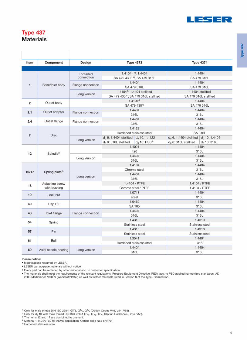
1) Only for male thread DIN ISO 228-1 G3/8, G1/2, G3/4 (Option Codes V49, V54, V55).2) Only for d0 10 with male thread DIN ISO 228-1 G3/8, G1/2, G3/4 (Option Codes V49, V54, V55).3) The items 12 and 17 are combined to one unit.4) Material 1.4404/316L for ASME application (Option code N68 or N70)5) Hardened stainless steel
Item Component Design Type 4373 Type 4374
1 Base/Inlet body
Threaded connection
1.41041) 4), 1.4404 1.4404SA 479 4301) 4), SA 479 316L SA 479 316L
Flange connection1.4404 1.4404
SA 479 316L SA 479 316L
Long version1.41042), 1.4404 stellited 1.4404 stellited
SA 479 4302) , SA 479 316L stellited SA 479 316L stellited
2 Outlet body 1.41044) 1.4404SA 479 4304) SA 479 316L
2.1 Outlet adaptor Flange connection1.4404 1.4404316L 316L
2.4 Outlet fl ange Flange connection1.4404 1.4404316L 316L
7 Disc
1.4122 1.4404Hardened stainless steel SA 316L
Long versiond0 6: 1.4404 stellited d0 10: 1.4122 d0 6: 1.4404 stellited d0 10: 1.4404d0 6: 316L stellited d0 10: HSS5) d0 6: 316L stellited d0 10: 316L
12 Spindle3)
1.4021 1.4404420 316L
Long Version1.4404 1.4404316L 316L
16/17 Spring plate3)
1.4104 1.4404Chrome steel 316L
Long version1.4404 1.4404316L 316L
18Adjusting screw
with bushing1.4104 / PTFE 1.4104 / PTFE
Chrome steel / PTFE 1.4104 / PTFE
19 Lock nut1.0718 1.4404steel 316L
40 Cap H21.0460 1.4404SA 105 316L
48 Inlet fl ange Flange connection1.4404 1.4404316L 316L
54 Spring1.4310 1.4310
Stainless steel Stainless steel
57 Pin1.4310 1.4310
Stainless steel Stainless steel
61 Ball1.3541 1.4401
Hardened stainless steel 316
69 Axial needle beering Long version1.4404 1.4404316L 316L
Please notice:
• Modifications reserved by LESER.• LESER can upgrade materials without notice.• Every part can be replaced by other material acc. to customer specification. • The materials shall meet the requirements of the relevant regulations (Pressure Equipment Directive (PED), acc. to PED applied harmonized standards, AD
2000-Merkblätter, VdTÜV (Werkstoffblätter) as well as further materials listed in Section 8 of the Type-Examination.
Typ
e 4
37
Type 437
Materials

10
Conventional design Long version
Actual Orifi ce diameter d0 [mm] 10 6 10
Actual Orifi ce area A0 [mm2] 78.5 28.3 78.5
Actual Orifi ce diameter d0 [inch] 0.394 0.236 0.394
Actual Orifi ce area A0 [inch2] 0.122 0.044 0.122 Base / Inlet body material: 1.4104 (430)1)
H2 Art. No. 4373.2) 2602 2622 2612
H3 Art. No. 4373.2)
pmax. = 16 barg2603 – –
H4 Art. No. 4373.2)2604 2624 2614
p [barg] S/G/L 0.1 – 93 S/G 180 – 365 S/G/L 93 –180
p [psig] S/G/L 1.5 – 1349 S/G 2611 – 5294 S/G/L 1349 – 2611
Base / Inlet body material: 1.4404 (316L)
H2 Art. No. 4374. 3142 3122 3152
H4 Art. No. 4374. 3144 3124 3154
p [barg] S/G/L 0.1 – 68 S/G 180 – 330 S/G/L 68 –180
p [psig] S/G/L 1.5 – 986 S/G 2611 – 4786 S/G/L 986 – 2611
1) Material 1.4404/316L for ASME application (Option code N68 or N70). 2) Type 4373 should not be selected when a „stainless steel“ valve is required due to corrosive medium.
Metal seat
Typ
e 4
37
Type 437
Article numbers

11
Conventional design – female thread
Conventional design – male thread Long version – male threadRequired installation diameter
d
Size Outlet bodyConventional design Long version
1/2" 3/4" 1" 1/2" 3/4" 1" 1/2" 3/4" 1"Actual Orifice diameter d0 [mm] 10 10 10 6 6 6 10 10 10
Actual Orifi ce area A0 [mm2] 78.5 78.5 78.5 28.3 28.3 28.3 78.5 78.5 78.5
Weight [kg] 1.2 1.6 1.6 1.4 2.1 2.1 1.4 2.1 2.1 Required installation diameter d [mm] 65 80 80 65 80 80 65 80 80
Inlet thread female
Size outlet bodyConventional design Long version
1/2" 3/4" 1" 1/2" 3/4" 1" 1/2" 3/4" 1"
Center to face [mm]
DIN ISO 228-1 GInlet 1/2" a 46 46 49 46 46 49 46 46 49
ISO 7-1/BS 21 Rc
ASME B1.20.1 NPT Inlet 3/4", 1" a 56 56 59 56 56 59 56 56 59Outlet b 30 37 37 30 37 37 30 37 37
Height [mm]
Inlet 1/2" H max. 209 209 212 230 230 233 230 230 233Inlet 3/4", 1" H max. 219 219 222 240 240 243 240 240 243
Inlet thread male
Size outlet bodyConventional design Long version
1/2" 3/4" 1" 1/2" 3/4" 1" 1/2" 3/4" 1"
Center to face [mm]
DIN ISO 228-1 GInlet a 33 33 36 33 33 36 33 33 36
Outlet b 30 37 37 30 37 37 30 37 37ISO 7-1/BS 21 R
Inlet a 31 31 34 31 31 34 31 31 34ASME B1.20.1 NPT
Outlet b 30 37 37 30 37 37 30 37 37
Height [mm]
Size inlet threadConventional design Long version
3/8" 1/2" 3/4" 1" 3/8" 1/2" 3/4" 1"DIN ISO 228-1 G H max. 208 210 212 217 229 231 233 238ISO 7-1/BS 21 R H max. – 213 214 220 – 234 235 241ASME B1.20.1 NPT H max. – 216 216 224 – 237 237 245Length of screwed end c [mm]
Size inlet thread 3/8" 1/2" 3/4" 1"DIN ISO 228-1 G 12 14 16 18ISO 7-1/BS 21 R – 19 20 23ASME B1.20.1 NPT – 22 22 27
Typ
e 4
37
Type 437
Dimensions and weights
Threaded connections [Metric units]

12
Conventional design – female thread
Conventional design – male thread Long version – male threadRequired installation diameter
d
Size Outlet bodyConventional design Long version
1/2" 3/4" 1" 1/2" 3/4" 1" 1/2" 3/4" 1"Actual Orifice diameter d0 [inch] 0.394 0.394 0.394 0.236 0.236 0.236 0.394 0.394 0.394
Actual Orifi ce area A0 [inch2] 0.122 0.122 0.122 0.044 0.044 0.044 0.122 0.122 0.122
Weight [lbs] 2.6 3.5 3.5 3.1 4.6 4.6 3.1 4.6 4.6 Required installation diameter d [inch] 29/16 35/32 35/32 29/16 35/32 35/32 29/16 35/32 35/32
Inlet thread female
Size outlet bodyConventional design Long version
1/2" 3/4" 1" 1/2" 3/4" 1" 1/2" 3/4" 1"
Center to face [inch]
DIN ISO 228-1 GInlet 1/2" a 113/16 113/16 115/16 113/16 113/16 115/16 113/16 113/16 115/16
ISO 7-1/BS 21 Rc
ASME B1.20.1 NPT Inlet 3/4", 1" a 27/32 27/32 25/16 27/32 27/32 25/16 27/32 27/32 25/16
Outlet b 13/16 115/32 115/32 13/16 115/32 115/32 13/16 115/32 115/32
Height [inch]
Inlet 1/2" H max. 87/32 87/32 811/32 91/16 91/16 93/16 91/16 91/16 93/16
Inlet 3/4", 1" H max. 85/8 85/8 83/4 97/16 97/16 99/16 97/16 97/16 99/16
Inlet thread male
Size outlet bodyConventional design Long version
1/2" 3/4" 1" 1/2" 3/4" 1" 1/2" 3/4" 1"
Center to face [inch]
DIN ISO 228-1 GInlet a 15/16 15/16 113/32 15/16 15/16 113/32 15/16 15/16 113/32
Outlet b 13/16 115/32 115/32 13/16 115/32 115/32 13/16 115/32 115/32
ISO 7-1/BS 21 RInlet a 17/32 17/32 111/32 17/32 17/32 111/32 17/32 17/32 111/32
ASME B1.20.1 NPT
Outlet b 13/16 115/32 115/32 13/16 115/32 115/32 13/16 115/32 115/32
Height [inch]
Size inlet threadConventional design Long version
3/8" 1/2" 3/4" 1" 3/8" 1/2" 3/4" 1"DIN ISO 228-1 G H max. 83/16 81/4 811/32 817/32 9 93/32 95/32 93/8
ISO 7-1/BS 21 R H max. – 83/8 813/32 821/32 – 97/32 91/4 915/32
ASME B1.20.1 NPT H max. – 81/2 81/2 813/16 – 95/16 95/16 921/32
Length of screwed end c [inch]
Size inlet thread 3/8" 1/2" 3/4" 1"DIN ISO 228-1 G 15/32
9/165/8
23/32
ISO 7-1/BS 21 R – 3/425/32
29/32
ASME B1.20.1 NPT – 7/87/8 11/16
Typ
e 4
37
Type 437
Dimensions and weights
Threaded connections [US units]

13
Conventional design Long version
Actual Orifice diameter d0 [mm] 10 6 10Actual Orifi ce area A0 [mm2] 78.5 28.3 78.5
DIN EN 1092-1 (Available fl ange sizes refer to page 04/05)
Flange rating class PN 40
Center to face [mm] Inlet a 103 103 103Outlet b 100 100 100
Height [mm] H max. 263 284 284 Flange rating class ≥ PN 160
Center to face [mm] Inlet a 103 103 103Outlet b 100 100 100
Height [mm] H max. 266 287 287
ASME B 16.5 (Available fl ange sizes refer to page 04/05)
Flange rating class 150
Center to face [mm] Inlet a 103 103 103Outlet b 100 100 100
Height [mm] H max. 263 284 284 Flange rating class ≥ 300
Center to face [mm] Inlet a 103 103 103Outlet b 100 100 100
Height [mm] H max. 266 287 287Note The outlet dimension b can differ at special combinations of nominal diameter and pressure range if fl anged connections are used at the inlet and outlet.
Special dimensions are possible. More information at [email protected]
Weight
To calculate the total weight use the formula: mT = mN + mF(Inlet) + mF(Outlet)
Weight net [kg]2.4 2.8 2.8(without inlet and outlet fl ange) mN
Flange dimensions
DIN EN 1092-1 / Flange rating PN ASME B16.5 / Flange rating
Size 40 100 160 250 320 400 Size 150 300 600 900 1500 2500
DN 15 NPS 1/2"
Flange thickness [mm] s 18 – 22 28 28 30 14 18 18 26 26 30.2
Weight slip on fl ange [kg] mF 0.8 – 1.2 2.5 2.5 3.6 0.6 0.9 0.9 2.1 2.1 3
DN 20 NPS 3/4"
Flange thickness [mm] s 20 22 – – – – 15 18 18 25.4 25.4 32
Weight slip on fl ange [kg] mF 1.1 1.3 – – – – 0.8 1.4 1.4 2.3 2.3 3.5
DN 25 NPS 1"
Flange thickness [mm] s 22 – 26 30 36 40 17 21.5 21.5 32.5 32.5 40
Weight slip on fl ange [kg] mF 1.3 – 2.6 3.5 5 7.5 1 2.1 21 4.1 4.1 5.1
Long versionConventional design
b
a
s
s ss
Typ
e 4
37
Type 437
Dimensions and weights
Flanged connections [Metric units]
14
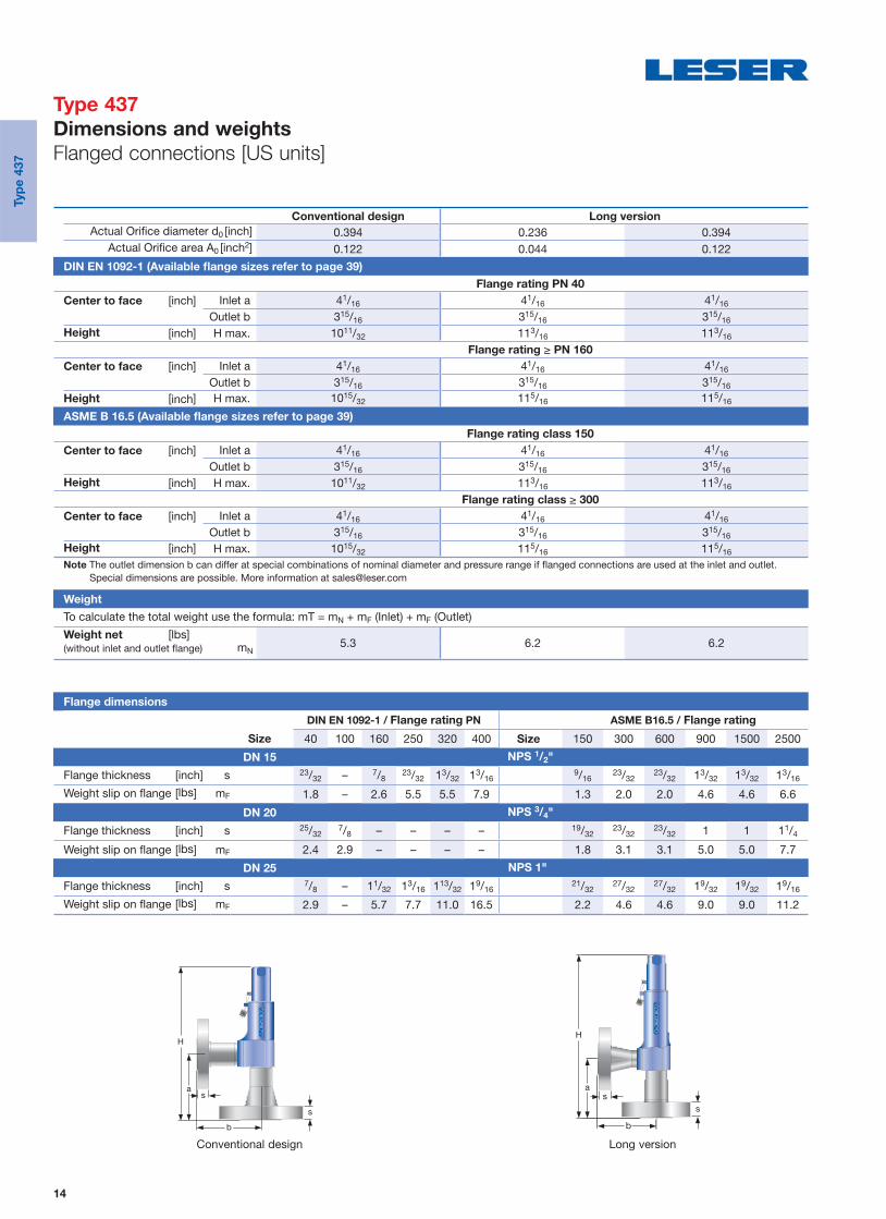
Conventional design Long version
Actual Orifice diameter d0 [inch] 0.394 0.236 0.394Actual Orifi ce area A0 [inch2] 0.122 0.044 0.122
DIN EN 1092-1 (Available fl ange sizes refer to page 39)
Flange rating PN 40
Center to face [inch] Inlet a 41/16 41/16 41/16
Outlet b 315/16 315/16 315/16
Height [inch] H max. 1011/32 113/16 113/16
Flange rating ≥ PN 160
Center to face [inch] Inlet a 41/16 41/16 41/16
Outlet b 315/16 315/16 315/16
Height [inch] H max. 1015/32 115/16 115/16
ASME B 16.5 (Available fl ange sizes refer to page 39)
Flange rating class 150
Center to face [inch] Inlet a 41/16 41/16 41/16
Outlet b 315/16 315/16 315/16
Height [inch] H max. 1011/32 113/16 113/16
Flange rating class ≥ 300
Center to face [inch] Inlet a 41/16 41/16 41/16
Outlet b 315/16 315/16 315/16
Height [inch] H max. 1015/32 115/16 115/16
Note The outlet dimension b can differ at special combinations of nominal diameter and pressure range if fl anged connections are used at the inlet and outlet. Special dimensions are possible. More information at [email protected]
Weight
To calculate the total weight use the formula: mT = mN + mF (Inlet) + mF (Outlet)
Weight net [lbs]5.3 6.2 6.2(without inlet and outlet fl ange) mN
Flange dimensions
DIN EN 1092-1 / Flange rating PN ASME B16.5 / Flange rating
Size 40 100 160 250 320 400 Size 150 300 600 900 1500 2500
DN 15 NPS 1/2"
Flange thickness [inch] s 23/32 – 7/823/32 13/32 13/16
9/1623/32
23/32 13/32 13/32 13/16
Weight slip on fl ange [lbs] mF 1.8 – 2.6 5.5 5.5 7.9 1.3 2.0 2.0 4.6 4.6 6.6
DN 20 NPS 3/4"
Flange thickness [inch] s 25/327/8 – – – – 19/32
23/3223/32 1 1 11/4
Weight slip on fl ange [lbs] mF 2.4 2.9 – – – – 1.8 3.1 3.1 5.0 5.0 7.7
DN 25 NPS 1"
Flange thickness [inch] s 7/8 – 11/32 13/16 113/32 19/1621/32
27/3227/32 19/32 19/32 19/16
Weight slip on fl ange [lbs] mF 2.9 – 5.7 7.7 11.0 16.5 2.2 4.6 4.6 9.0 9.0 11.2
Long versionConventional design
b
a
s
s ss
Typ
e 4
37
Type 437
Dimensions and weights
Flanged connections [US units]
15
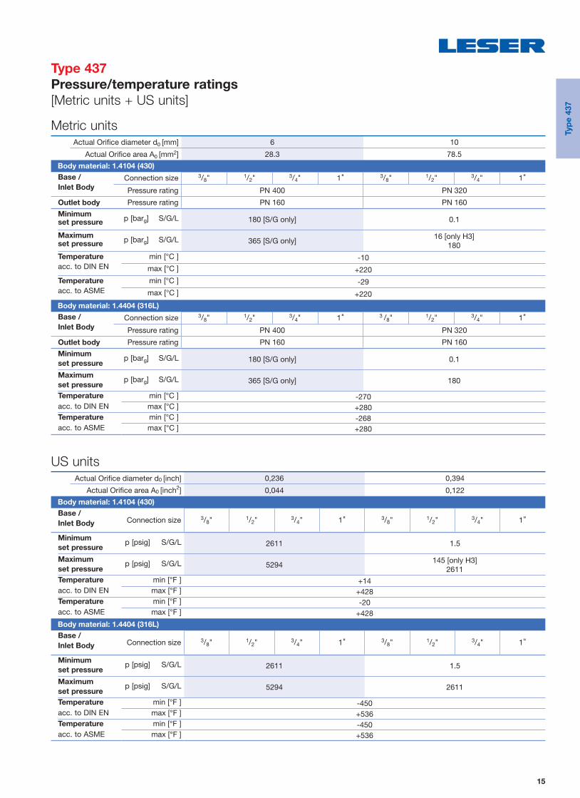
Metric units
Actual Orifi ce diameter d0 [mm] 6 10
Actual Orifi ce area A0 [mm2] 28.3 78.5 Body material: 1.4104 (430)
Base / Connection size 3/8" 1/2" 3/4" 1" 3/8" 1/2" 3/4" 1"Inlet Body Pressure rating PN 400 PN 320
Outlet body Pressure rating PN 160 PN 160 Minimum p [barg] S/G/L 180 [S/G only] 0.1set pressure
Maximum p [barg] S/G/L 365 [S/G only]16 [only H3]
180set pressure
Temperature min [°C ] -10acc. to DIN EN max [°C ] +220
Temperature min [°C ] -29acc. to ASME max [°C ] +220
Body material: 1.4404 (316L)
Base / Connection size 3/8" 1/2" 3/4" 1" 3 /8" 1/2" 3/4" 1"Inlet Body Pressure rating PN 400 PN 320
Outlet body Pressure rating PN 160 PN 160 Minimum p [barg] S/G/L 180 [S/G only] 0.1
set pressure
Maximum p [barg] S/G/L 365 [S/G only] 180set pressure
Temperature min [°C ] -270acc. to DIN EN max [°C ] +280
Temperature min [°C ] -268acc. to ASME max [°C ] +280
US units
Actual Orifi ce diameter d0 [inch] 0,236 0,394
Actual Orifi ce area A0 [inch2] 0,044 0,122 Body material: 1.4104 (430)
Base / Connection size 3/8" 1/2" 3/4" 1" 3/8" 1/2" 3/4" 1"
Inlet Body
Minimum p [psig] S/G/L 2611 1.5set pressure
Maximum p [psig] S/G/L 5294145 [only H3]
2611set pressure
Temperature min [°F ] +14acc. to DIN EN max [°F ] +428
Temperature min [°F ] -20acc. to ASME max [°F ] +428
Body material: 1.4404 (316L)
Base / Connection size 3/8" 1/2" 3/4" 1" 3/8" 1/2" 3/4" 1"
Inlet Body
Minimum p [psig] S/G/L 2611 1.5set pressure
Maximum p [psig] S/G/L 5294 2611set pressure
Temperature min [°F ] -450acc. to DIN EN max [°F ] +536
Temperature min [°F ] -450acc. to ASME max [°F ] +536
Typ
e 4
37
Type 437
Pressure/temperature ratings
[Metric units + US units]
16
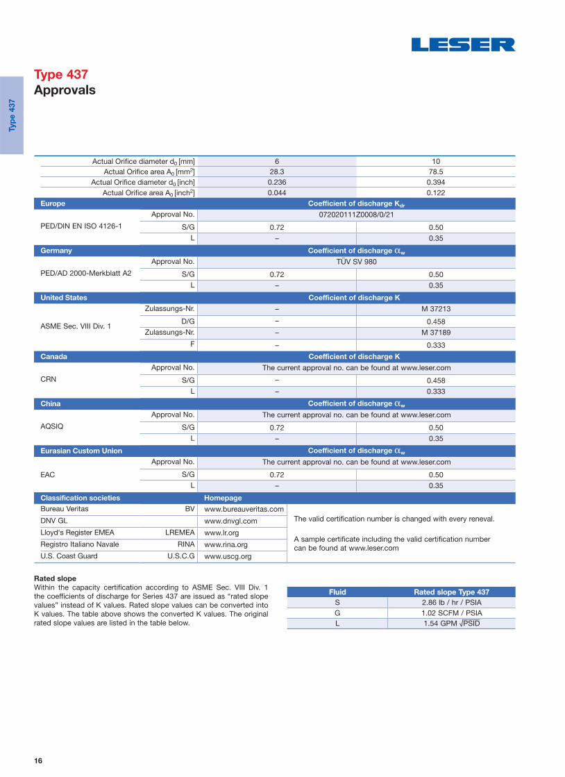
Actual Orifi ce diameter d0 [mm] 6 10 Actual Orifi ce area A0 [mm2] 28.3 78.5
Actual Orifi ce diameter d0 [inch] 0.236 0.394 Actual Orifi ce area A0 [inch2] 0.044 0.122
Europe Coefficient of discharge Kdr
PED/DIN EN ISO 4126-1
Approval No. 072020111Z0008/0/21
S/G 0.72 0.50L – 0.35
Germany Coefficient of discharge w
PED/AD 2000-Merkblatt A2
Approval No. TÜV SV 980
S/G 0.72 0.50L – 0.35
United States Coefficient of discharge K
ASME Sec. VIII Div. 1
Zulassungs-Nr. – M 37213
D/G – 0.458 Zulassungs-Nr. – M 37189
F – 0.333 Canada Coefficient of discharge K
CRN
Approval No. The current approval no. can be found at www.leser.com
S/G – 0.458L – 0.333
China Coefficient of discharge w
AQSIQ
Approval No. The current approval no. can be found at www.leser.com
S/G 0.72 0.50L – 0.35
Eurasian Custom Union Coefficient of discharge w
EAC
Approval No. The current approval no. can be found at www.leser.com
S/G 0.72 0.50L – 0.35
Classification societies Homepage
Bureau Veritas BV www.bureauveritas.comThe valid certification number is changed with every reneval.
A sample certificate including the valid certification number can be found at www.leser.com
DNV GL www.dnvgl.com
Lloyd‘s Register EMEA LREMEA www.lr.org
Registro Italiano Navale RINA www.rina.org
U.S. Coast Guard U.S.C.G www.uscg.org
Rated slope
Within the capacity certification according to ASME Sec. VIII Div. 1 the coefficients of discharge for Series 437 are issued as “rated slope values” instead of K values. Rated slope values can be converted into K values. The table above shows the converted K values. The original rated slope values are listed in the table below.
FluidFluid Rated slope Type 437Rated slope Type 437
S 2.86 lb / hr / PSIAG 1.02 SCFM / PSIAL 1.54 GPM √PSID
Typ
e 4
37
Type 437
Approvals

17
Type 438
Packed knob H4
Conventional design
Type 438
Cap H2
Long version
Type 438
Packed knob H4
Flanged connection
Contents Page
Designs 18
Materials 19
Article numbers 20
Dimensions and weights
• Threaded connections 21
• Flanged connections 23
Pressure / temperature ratings 25
Approvals 26
Typ
e 4
38
Type 438
Safety Relief Valves

18
Conventional design
Threaded connection
18 Adjusting screw with bushing
40 Cap H2
19 Lock nut
12 Spindle
54 Spring
2 Outlet body
7 O-ring disc
1 Body
16 Spring plate
Conventional design
Flange connection
Outlet flange 2.4
Outlet adaptor 2.1
Inlet flange 48
Long version
Threaded connection
Axial needle 69 beering
Typ
e 4
38
Type 438
Designs

19
Item Component Design Type 4383 Type 4384
1 Base / Inlet body
Threaded connection
1.41041) 2), 1.4404 1.4404SA 479 4301) 2), SA 479 316L SA 479 316L
Flange connection1.4404 1.4404
SA 479 316L SA 479 316L
Long version1.41041), 1.4404 1.4404
SA 479 4301), SA 479 316L SA 479 316L
2 Outlet body 1.41042) 1.4404SA 479 4302) SA 479 316L
2.1 Outlet adaptor Flange connection1.4404 1.4404316L 316L
2.4 Outlet fl ange Flange connection1.4404 1.4404316L 316L
7 O-ring disc 1.4404 1.4404SA 479 316L SA 479 316L
7.4 Soft seal O-ring
“N”3) NBR NBRNitrile-Butadiene Nitrile-Butadiene
“K”3) CR CRChloroprene Chloroprene
“D”3) EPDM EPDMEthylen-Propylene-Diene Ethylen-Propylene-Diene
“L”3) FKM FKM Fluorocarbon Fluorocarbon
“C”4) FFKM FFKMPerfl uor Perfl uor
12 Spindle
1.4021 1.4404420 316L
Long version1.4404 1.4404316L 316L
16 Spring plate
1.4104 1.4404Chrome steel 316L
Long version1.4404 1.4404316L 316L
18Adjusting screw
with bushing1.4104 / PTFE 1.4404 / PTFE
Chrome steel / PTFE 316L / PTFE
19 Lock nut1.0718 1.4404Steel 316L
40 Cap H21.0460 1.4404SA 105 316L
48 Inlet fl ange Flange connection1.4404 1.4404316L 316L
54 Spring1.4310 1.4310
Stainless steel Stainless steel
69 Axial needle beering Long version1.4404 1.4404316L 316L
1) Only for male thread DIN ISO 228-1 G3/8, G1/2, G3/4 (Option codes V49, V54, V55).2) Material 1.4404/316L for ASME application (Option code N68 or N70)3) Long version: O-ring 90 Shore for set pressures > 120 bar4) O-ring 90 Shore for set pressures > 40 bar
Please notice:
• Modifications reserved by LESER.• LESER can upgrade materials without notice.• Every part can be replaced by other material acc. to customer specification. • The materials shall meet the requirements of the relevant regulations (Pressure Equipment Directive (PED), acc. to PED applied harmonized standards, AD
2000-Merkblätter, VdTÜV (Werkstoffblätter) as well as further materials listed in Section 8 of the Type-Examination.
Typ
e 4
38
Type 438
Materials

20
Conventional design Long version
Actual Orifi ce diameter d0 [mm] 10 10
Actual Orifi ce area A0 [mm2] 78.5 78.5
Actual Orifi ce diameter d0 [inch] 0.394 0.394
Actual Orifi ce area A0 [inch2] 0.122 0.122
O-ring material NBR “N” J30 NBR “N” J303)
CR “K” J21 CR “K” J213)
EPDM “D” J22 EPDM “D” J223)
FKM “L” J23 FKM “L” J233)
FFKM “C” J204) FFKM “C” J204)
Base/Inlet body material: 1.4104 (430)1)
H2 Art. No. 4383.2) 2862 2872
H3 Art. No. 4383.2)
pmax = 16 barg
2863 –
H4 Art. No. 4383.2) 2864 2874
p [barg] S/G/L 5 – 93 93 – 180
p [psig] S/G/L 72.5 – 1349 1349 – 2611
Base/Inlet body material: 1.4404 (316L)
H2 Art. No. 4384. 2982 2992
H4 Art. No. 4384. 2984 2994
p [barg] S/G/L 5 – 68 68 – 180
p [psig] S/G/L 72.5 – 986 986 – 2611
1) Material 1.4404/316L for ASME application (Option code N68 or N70)2) Type 4383 should not be selected when a „stainless steel“ valve is required due to corrosive medium.3) O-ring 90 Shore for set pressures > 120 bar4) O-ring 90 Shore for set pressures > 40 bar
O-ring disc
Typ
e 4
38
Type 438
Article numbers

21
Size Outlet bodyConventional design Long version
1/2" 3/4" 1" 1/2" 3/4" 1"Actual Orifice diameter d0 [mm] 10 10 10 10 10 10
Actual Orifi ce area A0 [mm2] 78.5 78.5 78.5 78.5 78.5 78.5
Weight [kg] 1.2 1.6 1.6 1.4 2.1 2.1 Required installation diameter d [mm] 65 80 80 65 80 80
Inlet thread female
Size outlet bodyConventional design Long version
1/2" 3/4" 1" 1/2" 3/4" 1"
Center to face [mm]
DIN ISO 228-1 GInlet 1/2" a 46 46 49 46 46 49
ISO 7-1/BS 21 Rc
ASME B1.20.1 NPT Inlet 3/4", 1" a 56 56 59 56 56 59Outlet b 30 37 37 30 37 37
Height [mm]
Inlet 1/2" H max. 209 209 212 230 230 233Inlet 3/4", 1" H max. 219 219 222 240 240 243
Inlet thread male
Size outlet bodyConventional design Long version
1/2" 3/4" 1" 1/2" 3/4" 1"
Center to face [mm]
DIN ISO 228-1 GInlet a 33 33 36 33 33 36
Outlet b 30 37 37 30 37 37ISO 7-1/BS 21 R
Inlet a 31 31 34 31 31 34ASME B1.20.1 NPT
Outlet b 30 37 37 30 37 37
Height [mm]
Size inlet threadConventional design Long version
3/8" 1/2" 3/4" 1" 3/8" 1/2" 3/4" 1"DIN ISO 228-1 G H max. 208 210 212 217 229 231 233 238ISO 7-1/BS 21 R H max. – 213 214 220 – 234 235 241ASME B1.20.1 NPT H max. – 216 216 224 – 237 237 245
Length of screwed end c [mm]
Size inlet thread 3/8" 1/2" 3/4" 1"DIN ISO 228-1 G 12 14 16 18ISO 7-1/BS 21 R – 19 20 23ASME B1.20.1 NPT – 22 22 27
d
Required installation diameter Conventional design – female thread
Conventional design – male thread Long version – male thread
Typ
e 4
38
Type 438
Dimensions and weights
Threaded connections [Metric units]

22
Conventional design – female thread
Conventional design – male thread Long version – male threadRequired installation diameter
d
Size Outlet bodyConventional design Long version
1/2" 3/4" 1" 1/2" 3/4" 1"Actual Orifice diameter d0 [inch] 0.394 0.394 0.394 0.394 0.394 0.394
Actual Orifi ce area A0 [inch2] 0.122 0.122 0.122 0.122 0.122 0.122
Weight [lbs] 2.6 3.5 3.5 3.1 4.6 4.6 Required installation diameter d [inch] 29/16 35/32 35/32 29/16 35/32 35/32
Inlet thread female
Size outlet bodyConventional design Long version
1/2" 3/4" 1" 1/2" 3/4" 1"
Center to face [inch]
DIN ISO 228-1 GInlet 1/2" a 113/16 113/16 115/16 113/16 113/16 115/16
ISO 7-1/BS 21 Rc
ASME B1.20.1 NPT Inlet 3/4", 1" a 27/32 27/32 25/16 27/32 27/32 25/16
Outlet b 13/16 115/32 115/32 13/16 115/32 115/32
Height [inch]
Inlet 1/2" H max. 87/32 87/32 811/32 91/16 91/16 93/16
Inlet 3/4", 1" H max. 85/8 85/8 83/4 97/16 97/16 99/16
Inlet thread male
Size outlet bodyConventional design Long version
1/2" 3/4" 1" 1/2" 3/4" 1"
Center to face [inch]
DIN ISO 228-1 GInlet a 15/16 15/16 113/32 15/16 15/16 113/32
Outlet b 13/16 115/32 115/32 13/16 115/32 115/32
ISO 7-1/BS 21 RInlet a 17/32 17/32 111/32 17/32 17/32 111/32
ASME B1.20.1 NPT
Outlet b 13/16 115/32 115/32 13/16 115/32 115/32
Height [inch]
Size inlet threadConventional design Long version
3/8" 1/2" 3/4" 1" 3/8" 1/2" 3/4" 1"DIN ISO 228-1 G H max. 83/16 81/4 811/32 817/32 9 93/32 95/32 93/8
ISO 7-1/BS 21 R H max. – 83/8 813/32 821/32 – 97/32 91/4 915/32
ASME B1.20.1 NPT H max. – 81/2 81/2 813/16 – 95/16 95/16 921/32
Length of screwed end c [inch]
Size inlet thread 3/8" 1/2" 3/4" 1"DIN ISO 228-1 G 15/32
9/165/8
23/32
ISO 7-1/BS 21 R – 3/425/32
29/32
ASME B1.20.1 NPT – 7/87/8
11/16
Typ
e 4
38
Type 438
Dimensions and weights
Threaded connections [US units]

23
Conventional design Long version
Actual Orifice diameter d0 [mm] 10 10 Actual Orifi ce area A0 [mm2] 78.5 78.5
DIN EN 1092-1
Flange rating PN 40
Center to face [mm] Inlet a 103 103
Outlet b 100 100
Height [mm] H max. 263 284
Flange rating ≥ PN 160
Center to face [mm] Inlet a 103 103
Outlet b 100 100
Height [mm] H max. 266 287
ASME B 16.5
Flange rating class 150
Center to face [mm] Inlet a 103 103
Outlet b 100 100
Height [mm] H max. 263 284
Flange rating class ≥ 300
Center to face [mm] Inlet a 103 103
Outlet b 100 100
Height [mm] H max. 266 287
Weight
For the calculation of the total weight please use the Formular: WT = WN + WF (Inlet) + WF (Outlet)Weight net [kg]
2.4 2.8(without inlet and outlet fl ange) WN
Flange dimensions and availability
DIN EN 1092-1 / Flange rating PN ASME B16.5 / Flange rating class
Size 40 100 160 250 320 400 Size 150 300 600 900 1500 2500
DN 15 NPS 1/2"
Flange thickness [mm] s 18 – 22 28 28 30 14 18 18 26 26 30.2
Weight slip on fl ange [kg] WF 0.8 – 1.2 2.5 2.5 3.6 0.6 0.9 2.0 2.1 2.1 3
DN 20 NPS 3/4"
Flange thickness [mm] s 20 22 – – – – 15 18 18 25.4 25.4 32
Weight slip on fl ange [kg] WF 1.1 1.3 – – – – 0.8 1.4 1.4 2.3 2.3 3.5
DN 25 NPS 1"
Flange thickness [mm] s 22 – 26 30 36 40 17 21.5 21.5 32.5 32.5 40
Weight slip on fl ange [kg] WF 1.3 – 2.6 3.5 5 7.5 1 2.1 2.1 4.1 4.1 5.1
Long versionConventional design
b
a
s
s ss
Typ
e 4
38
Type 438
Dimensions and weights
Flanged connections [Metric units]

24
Conventional design Long version
Actual Orifice diameter d0 [inch] 0.394 0.394 Actual Orifi ce area A0 [inch2] 0.122 0.122
DIN EN 1092-1 (Available fl ange sizes refer to page 04/05)
Flange rating PN 40
Center to face [inch] Inlet a 41/16 41/16
Outlet b 315/16 315/16
Height [inch] H max. 1011/32 103/16
Flange rating ≥ PN 160
Center to face [inch] Inlet a 41/16 41/16
Outlet b 315/16 315/16
Height [inch] H max. 1015/32 115/16
ASME B 16.5 (Available fl ange sizes refer to page 04/05)
Flange rating class 150
Center to face [inch] Inlet a 41/16 41/16
Outlet b 315/16 315/16
Height [inch] H max. 1011/32 113/16
Flange rating class ≥ 300
Center to face [inch] Inlet a 41/16 41/16
Outlet b 315/16 315/16
Height [inch] H max. 1015/32 115/16
Weight
For the calculation of the total weight please use the Formular: WT = WN + WF (Inlet) + WF (Outlet)Weight net [lbs]
5.3 6.2(without inlet and outlet fl ange) WN
Flange dimensions and availability
DIN EN 1092-1 / Flange rating PN ASME B16.5 / Flange rating class
Size 40 100 160 250 320 400 Size 150 300 600 900 1500 2500
DN 15 NPS 1/2"
Flange thickness [inch] s 23/32 – 7/8 13/32 13/32 16/329/16
23/3223/32 11/32 11/32 16/32
Weight slip on fl ange [lbs] WF 1.8 – 2.6 5.5 5.5 7.9 1.3 2.0 2.0 4.6 4.6 6.6
DN 20 NPS 3/4"
Flange thickness [inch] s 25/3228/32 – – – – 19/32
23/3223/32 1 1 18/32
Weight slip on fl ange [lbs] WF 2.4 2.9 – – – – 1.8 3.1 3.1 5.0 5.0 7.7
DN 25 NPS 1"
Flange thickness [inch] s 7/8 – 11/32 16/32 113/32 118/3221/32
27/3227/32 19/32 19/32 118/32
Weight slip on fl ange [lbs] WF 2.9 – 5.7 7.7 11.0 16.5 2.2 4.6 4.6 9.0 9.0 11.2
Long versionConventional design
b
a
s
s ss
Typ
e 4
38
Type 438
Dimensions and weights
Flanged connections [US units]
25
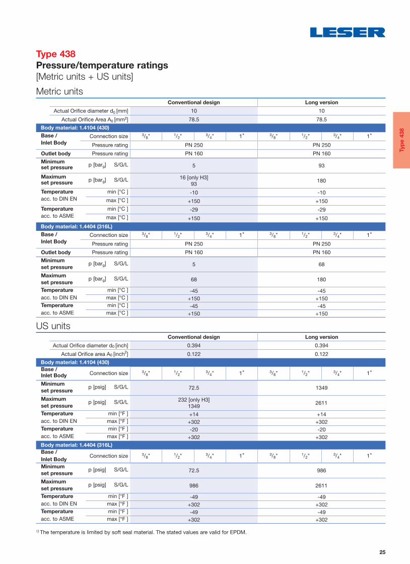
Metric unitsConventional design Long version
Actual Orifi ce diameter d0 [mm] 10 10
Actual Orifi ce Area A0 [mm2] 78.5 78.5 Body material: 1.4104 (430)
Base / Connection size 3/8" 1/2" 3/4" 1" 3/8" 1/2" 3/4" 1"Inlet Body Pressure rating PN 250 PN 250
Outlet body Pressure rating PN 160 PN 160 Minimum p [barg] S/G/L 5 93set pressure
Maximum p [barg] S/G/L 16 [only H3]93
180set pressure
Temperature min [°C ] -10 -10acc. to DIN EN max [°C ] +150 +150
Temperature min [°C ] -29 -29acc. to ASME max [°C ] +150 +150
Body material: 1.4404 (316L)
Base / Connection size 3/8" 1/2" 3/4" 1" 3/8" 1/2" 3/4" 1"Inlet Body Pressure rating PN 250 PN 250
Outlet body Pressure rating PN 160 PN 160 Minimum p [barg] S/G/L 5 68
set pressure
Maximum p [barg] S/G/L 68 180set pressure
Temperature min [°C ] -45 -45acc. to DIN EN max [°C ] +150 +150
Temperature min [°C ] -45 -45acc. to ASME max [°C ] +150 +150
US unitsConventional design Long version
Actual Orifi ce diameter d0 [inch] 0.394 0.394
Actual Orifi ce area A0 [inch2] 0.122 0.122 Body material: 1.4104 (430)
Base / Connection size 3/8" 1/2" 3/4" 1" 3/8" 1/2" 3/4" 1"
Inlet Body
Minimum p [psig] S/G/L 72.5 1349set pressure
Maximum p [psig] S/G/L 232 [only H3]1349
2611set pressure
Temperature min [°F ] +14 +14acc. to DIN EN max [°F ] +302 +302
Temperature min [°F ] -20 -20acc. to ASME max [°F ] +302 +302
Body material: 1.4404 (316L)
Base / Connection size 3/8" 1/2" 3/4" 1" 3/8" 1/2" 3/4" 1"
Inlet Body
Minimum p [psig] S/G/L 72.5 986set pressure
Maximum p [psig] S/G/L 986 2611set pressure
Temperature min [°F ] -49 -49acc. to DIN EN max [°F ] +302 +302
Temperature min [°F ] -49 -49acc. to ASME max [°F ] +302 +302
1) The temperature is limited by soft seal material. The stated values are valid for EPDM.
Typ
e 4
38
Type 438
Pressure/temperature ratings
[Metric units + US units]

26
Actual Orifi ce diameter d0 [mm] 10 Actual Orifi ce area A0 [mm2] 78.5
Actual Orifi ce diameter d0 [inch] 0.394 Actual Orifi ce area A0 [inch2] 0.122
Europe Coefficient of discharge Kdr
PED / DIN EN ISO 4126-1Approval No. 072020111Z0008/0/21
S/G 0.40L 0.33
Germany Coefficient of discharge w
PED / AD 2000-Merkblatt A2
Approval No. TÜV SV 980
S/G 0.40L 0.33
United States Coefficient of discharge K
ASME Sec. VIII Div. 1
Approval No. M 37190
S/G 0.406
Approval No. M 371202
L 0.322 Canada Coefficient of discharge K
CRN
Approval No. The current approval no. can be found at www.leser.com.
S/G 0.406
L 0.322
China Coefficient of discharge w
AQSIQ
Approval No. The current approval no. can be found at www.leser.com.
S/G 0.40L 0.33
Eurasian Custom Union Coefficient of discharge w
EAC
Approval No. The current approval no. can be found at www.leser.com.
S/G 0.40L 0.33
Classification societies Homepage
Bureau Veritas BV www.bureauveritas.comThe valid certification number is changed with every reneval.
A sample certificate including the valid certification number can be found at www.leser.com
DNV GL www.dnvgl.com
Lloyd‘s Register EMEA LREMEA www.lr.org
Registro Italiano Navale RINA www.rina.org
U.S. Coast Guard U.S.C.G www.uscg.org
Rated slope
Within the capacity certification according to ASME Sec. VIII Div. 1 the coefficients of discharge for Series 437 are issued as “rated slope values” instead of K values. Rated slope values can be converted into K values. The table above shows the converted K values. The original rated slope values are listed in the table below.
FluidFluid Rated slope Type 438Rated slope Type 438
S 2.55 lb / hr / PSIAG 0.904 SCFM / PSIAL 1.49 GPM √PSID
Typ
e 4
38
Type 438
Approvals

27
Type 439
Packed knob H4
Conventional design
Type 439
Cap H2
Long version
Type 439
Packed knob H4
Flanged connection
Contents Page
Designs 18
Materials 19
Article numbers 20
Dimensions and weights
• Threaded connections 21
• Flanged connections 23
Pressure / temperature ratings 25
Approvals 26
Series 437
Available options 37
Available connections
• Threaded connections 38
• Flanged connections 39
Typ
e 4
39
Type 439
Safety Relief Valves

28
Conventional design
Flange connection
18 Adjusting screw with bushing
40 Cap H2
16 Spring plate
12 Spindle54 Spring
19 Lock nut
2 Outlet body17 Spring plate57 Pin61 Ball7 Disc
1 Body
Outlet flange 2.4
Outlet adaptor 2.1
Inlet flange 48
Conventional design
Threaded connectionConventional design
Threaded connection
Typ
e 4
39
Type 439
Designs

29
Item Component Design Type 4393 Type 4394
1 Base / Inlet body
Threadedconnection
1.41041) 3), 1.4404 1.4404SA 479 4301) 3), SA 479 316L SA 479 316L
Flange connection1.4404 1.4404
SA 479 316L SA 479 316L
2 Outlet body 1.41043) 1.4404SA 479 4303) SA 479 316L
2.1 Outlet adaptor Flange connection1.4404 1.4404316L 316L
2.4 Outlet fl ange Flange connection1.4404 1.4404316L 316L
7Vulcanized soft 1.4404 1.4404
seal disc SA 479 316L SA 479 316L
7.1Disc with
vulcanized soft seal
“N”NBR NBR
Nitrile-Butadiene Nitrile-Butadiene
“K”CR CR
Chloroprene Chloroprene
“D”EPDM EPDM
Ethylen-Propylene-Diene Ethylen-Propylene-Diene
“L”FKM FKM
Fluorocarbon Fluorocarbon
“C”FFKM FFKM
Perfl uor Perfl uor
12 Spindle2) 1.4021 1.4404420 316L
16/17 Spring plate2) 1.4104 1.4404Chrome steel 316L
18Adjusting screw
with bushing1.4104 / PTFE 1.4404 / PTFE
Chrome steel / PTFE 316L / PTFE
19 Lock nut1.0718 1.4404Steel 316L
40 Cap H21.0460 1.4404SA 105 316L
48 Inlet fl ange Flange connection1.4404 1.4404316L 316L
54 Spring1.4310 1.4310
Stainless steel Stainless steel
57 Pin1.4310 1.4310
Stainless steel Stainless steel
61 Ball1.3541 1.4401
Hardened stainless steel 316
1) Only for male thread DIN ISO 228-1 G3/8, G1/2, G3/4 (Option codes V49, V54, V55).2) The items 12 and 17 are combined to one unit.3) Material 1.4404/316L for ASME application (Option code N68 or N70)
Please notice:
• Modifications reserved by LESER.• LESER can upgrade materials without notice.• Every part can be replaced by other material acc. to customer specification. • The materials shall meet the requirements of the relevant regulations (Pressure Equipment Directive (PED), acc. to PED applied harmonized standards, AD
2000-Merkblätter, VdTÜV (Werkstoffblätter) as well as further materials listed in Section 8 of the Type-Examination.
Typ
e 4
39
Type 439
Materials

30
Actual Orifi ce diameter d0 [mm] 10
Actual Orifi ce area A0 [mm2] 78.5
Actual Orifi ce diameter d0 [inch] 0.394
Actual Orifi ce area A0 [inch2] 0.122
Soft seal material NBR “N” J30
CR “K” J21
EPDM “D” J22
FKM “L” J23
FFKM “C” J20 Base / Inlet body material: 1.4104 (430)1)
H2 Art. No. 4393.2) 2882
H3 Art. No. 4393.2)
pmax = 10 barg2883
H4 Art. No. 4393.2) 2884
p [barg] S/G/L 0.1 – 16
p [psig] S/G/L 1.5 – 232
Base / Inlet body material: 1.4404 (316L)
H2 Art. No. 4394. 2892
H4 Art. No. 4394. 2894
p [barg] S/G/L 0.1 – 16
p [psig] S/G/L 1.5 – 232
1) Material 1.4404/316L for ASME application (Option code N68 or N70)2) Type 4393 should not be selected when a „stainless steel“ valve is required due to corrosive medium.
Vulcanized soft seat
Typ
e 4
39
Type 439
Article numbers

31
Conventional design – Female thread
Conventional design – Male threadRequired installation diameter
d
Size Outlet body 1/2" 3/4" 1"Actual Orifice diameter d0 [mm] 10 10 10
Actual Orifi ce area A0 [mm2] 78.5 78.5 78.5
Weight [kg] 1.2 1.6 1.6 Required installation diameter d [mm] 65 80 80
Inlet thread female Size outlet body 1/2" 3/4" 1"
Center to face [mm]
DIN ISO 228-1 GInlet 1/2" a 46 46 49
ISO 7-1/BS 21 Rc
ASME B1.20.1 NPT Inlet 3/4", 1" a 56 56 59Outlet b 30 37 37
Height [mm]
Inlet 1/2" H max. 209 209 212Inlet 3/4", 1" H max. 219 219 222
Inlet thread maleSize outlet body 1/2" 3/4" 1"
Center to face [mm]
DIN ISO 228-1 GInlet a 33 33 36
Outlet b 30 37 37ISO 7-1/BS 21 R
Inlet a 31 31 34ASME B1.20.1 NPT
Outlet b 30 37 37
Height [mm]
Size inlet thread 3/8" 1/2" 3/4" 1"DIN ISO 228-1 G H max. 208 210 212 217ISO 7-1/BS 21 R H max. – 213 214 220ASME B1.20.1 NPT H max. – 216 216 224
Length of screwed end c [mm]
Size inlet thread 3/8" 1/2" 3/4" 1"DIN ISO 228-1 G 12 14 16 18ISO 7-1/BS 21 R – 19 20 23ASME B1.20.1 NPT – 22 22 27
Typ
e 4
39
Type 439
Dimensions and weights
Threaded connections [Metric units]

32
Size Outlet body 1/2" 3/4" 1"Actual Orifice diameter d0 [inch] 0.394 0.394 0.394
Actual Orifi ce area A0 [inch2] 0.122 0.122 0.122
Weight [lbs] 2.6 3.5 3.5 Required installation diameter d [inch] 29/16 35/32 35/32
Inlet thread female Size outlet body 1/2" 3/4" 1"
Center to face [inch]
DIN ISO 228-1 GInlet 1/2" a 113/16 113/16 115/16
ISO 7-1/BS 21 Rc
ASME B1.20.1 NPT Inlet 3/4", 1" a 27/32 27/32 25/16
Outlet b 13/16 115/32 115/32
Height [inch]
Inlet 1/2" H max. 87/32 87/32 811/32
Inlet 3/4", 1" H max. 85/8 85/8 83/4
Inlet thread maleSize outlet body 1/2" 3/4" 1"
Center to face [inch]
DIN ISO 228-1 GInlet a 15/16 15/16 113/32
Outlet b 13/16 115/32 115/32
ISO 7-1/BS 21 RInlet a 17/32 17/32 111/32
ASME B1.20.1 NPT
Outlet b 13/16 115/32 115/32
Height [inch]
Size inlet thread 3/8" 1/2" 3/4" 1"DIN ISO 228-1 G H max. 83/16 81/4 811/32 817/32
ISO 7-1/BS 21 R H max. – 83/8 813/32 821/32
ASME B1.20.1 NPT H max. – 81/2 81/2 813/16
Length of screwed end c [inch]
Size inlet thread 3/8" 1/2" 3/4" 1"DIN ISO 228-1 G 15/32
9/165/8
23/32
ISO 7-1/BS 21 R – 3/425/32
29/32
ASME B1.20.1 NPT – 7/87/8 11/16
Conventional design – Female thread
Conventional design – Male threadRequired installation diameter
d
Typ
e 4
39
Type 439
Dimensions and weights
Threaded connections [US units]

33
Actual Orifice diameter d0 [mm] 10Actual Orifi ce area A0 [mm2] 78.5
DIN EN 1092-1
Flange rating PN 40
Center to face [mm] Inlet a 103Outlet b 100
Height [mm] H max. 263 Flange rating ≥ PN 160
Center to face [mm] Inlet a 103Outlet b 100
Height [mm] H max. 266
ASME B 16.5
Flange rating class 150
Center to face [mm] Inlet a 103Outlet b 100
Height [mm] H max. 263 Flange rating class ≥ 300
Center to face [mm] Inlet a 103Outlet b 100
Height [mm] H max. 266
Note The outlet dimension b can differ at special combinations of nominal diameter and pressure range if fl anged connections are used at the inlet and outlet.Special dimensions are possible. More information at [email protected].
Weight
To calculate the total weight use the formula: mT = mN + mF (Inlet) + mF (Outlet)Weight net [kg]
2.4(without inlet and outlet fl ange) mN
Flange dimensions
DIN EN 1092-1 / Flange rating PN ASME B16.5 / Flange rating
Size 40 100 160 250 320 400 Size 150 300 600 900 1500 2500
DN 15 NPS 1/2"
Flange thickness [mm] s 18 – 22 28 28 30 14 18 18 26 26 30.2Weight slip on fl ange [kg] mF 0.8 – 1.2 2.5 2.5 3.6 0.6 0.9 0.9 2.1 2.1 3
DN 20 NPS 3/4"
Flange thickness [mm] s 20 22 – – – – 15 18 18 25.4 25.4 32Weight slip on fl ange [kg] mF 1.1 1.3 – – – – 0.8 1.4 1.4 2.3 2.3 3.5
DN 25 NPS 1"
Flange thickness [mm] s 22 – 26 30 36 40 17 21.5 21.5 32.5 32.5 40Weight slip on fl ange [kg] mF 1.3 – 2.6 3.5 5 7.5 1 2.1 2.1 4.1 4.1 5.1
b
a
s
s
Conventional design
Typ
e 4
39
Type 439
Dimensions and weights
Flanged connections [Metric units]

34
Actual Orifice diameter d0 [inch] 0.394Actual Orifi ce area A0 [inch2] 0.122
DIN ISO 1092-1
Flange rating PN 40
Center to face [inch] Inlet a 41/16
Outlet b 315/16
Height [inch] H max. 1011/32
Flange rating ≥ PN 160
Center to face [inch] Inlet a 41/16
Outlet b 315/16
Height [inch] H max. 1015/32
ASME B 16.5
Flange rating class 150
Center to face [inch] Inlet a 41/16
Outlet b 315/16
Height [inch] H max. 1011/32
Flange rating class ≥ 300
Center to face [inch] Inlet a 41/16
Outlet b 315/16
Height [inch] H max. 1015/32
Note The outlet dimension b can differ at special combinations of nominal diameter and pressure range if fl anged connections are used at the inlet and outlet.Special dimensions are possible. More information at [email protected].
Weight
To calculate the total weight use the formula: mT = mN + mF (Inlet) + mF (Outlet)Weight net [lbs]
5.3(without inlet and outlet fl ange) mN
Flange dimensions
DIN ISO 1092-1 / Flange rating PN ASME B16.5 / Flange rating
Size 40 100 160 250 320 400 Size 150 300 600 900 1500 2500
DN 15 NPS 1/2"
Flange thickness [inch] s 23/32 – 7/8 13/32 13/32 13/169/16
23/3223/32 11/32 11/32 13/16
Weight slip on fl ange [lbs] mF 1.8 – 2.6 5.5 5.5 8.0 1.3 2.0 2.0 4.6 4.6 6.6
DN 20 NPS 3/4"
Flange thickness [inch] s 25/327/8 – – – – 19/32
23/3223/32 1 1 11/4
Weight slip on fl ange [lbs] mF 2.4 2.9 – – – – 1.8 3.1 3.1 5.0 5.0 7.7
DN 25 NPS 1"
Flange thickness [inch] s 7/8 – 11/32 13/16 113/32 19/1621/32
27/3227/32 19/32 19/32 19/16
Weight slip on fl ange [lbs] mF 2.9 – 5.7 7.7 11.0 16.5 2.2 4.6 4.6 9.0 9.0 11.2
b
a
s
s
Conventional design
Typ
e 4
39
Type 439
Dimensions and weights
Flanged connections [US units]

35
US units
Actual Orifi ce diameter d0 [inch] 0.394
Actual Orifi ce area A0 [inch2] 0.122 Body material: 1.4104 (430)
Base / Connection size 3/8" 1/2" 3/4" 1"
Inlet Body
Minimump [psig] S/G/L 1.5
set pressure
Maximump [psig] S/G/L 232
set pressure
Temperature min [°F ] +14acc. to DIN EN max [°F ] +302
Temperature min [°F ] -20acc. to ASME max [°F ] +302
Body material: 1.4404 (316L)
Base / Connection size 3/8" 1/2" 3/4" 1"
Inlet Body
Minimump [psig] S/G/L 1.5
set pressure
Maximump [psig] S/G/L 232
set pressure
Temperature min [°F ] -49acc. to DIN EN max [°F ] +302
Temperature min [°F ] -49acc. to ASME max [°F ] +302
Metric units
Actual Orifi ce diameter d0 [mm] 10
Actual Orifi ce Area A0 [mm2] 78.5 Body material: 1.4104 (430)
Base / Connection size 3/8"1/2" 3/4" 1"
Inlet Body Pressure rating PN 250
Outlet body Pressure rating PN 160 Minimum
p [barg] S/G/L 0.1set pressure
Maximump [barg] S/G/L 16set pressure
Temperature min. [°C ] -10acc. to DIN EN max. [°C ] +150
Temperature min. [°C ] -29acc. to ASME max. [°C ] +150
Body material: 1.4404 (316L)
Base / Connection size 3 /8"1/2" 3/4" 1"
Inlet Body Pressure rating PN 250
Outlet body Pressure rating PN 160 Minimum
p [barg] S/G/L 0.1set pressure
Maximump [barg] S/G/L 16
set pressure
Temperature min. [°C ] -45acc. to DIN EN max. [°C ] +150
Temperature min. [°C ] -45acc. to ASME max. [°C ] +150
Typ
e 4
39
Type 439
Pressure/temperature ratings
[Metric units + US units]

36
Actual Orifi ce diameter d0 [mm] 10 Actual Orifi ce area A0 [mm2] 78.5
Actual Orifi ce diameter d0 [inch] 0.394 Actual Orifi ce area A0 [inch2] 0.122
Europa Coefficient of discharge Kdr
PED / DIN EN ISO 4126-1
Approval No. 072020111Z0008/0/21
S/G 0.45
L 0.37 Germany Coefficient of discharge w
PED / AD 2000-Merkblatt A2Approval No. TÜV SV 980
S/G 0.45
L 0.37 United States Coefficient of discharge K
ASME Sec. VIII Div. 1
Approval No. M 37190
S/G 0.406Approval No. M 37202
L 0.322 Canada Coefficient of discharge K
CRN
Approval No. The current approval no. can be found at www.leser.com
S/G 0.406
L 0.322 China Coefficient of discharge w
AQSIQ
Approval No. The current approval no. can be found at www.leser.com
S/G 0.45
L 0.37 Eurasian Custom Union Coefficient of discharge w
EAC
Approval No. The current approval no. can be found at www.leser.com
S/G 0.45
L 0.37 Classification societies Homepage
Bureau Veritas BV www.bureauveritas.comThe valid certification number is changed with every reneval.
A sample certificate including the valid certification number can be found at www.leser.com
DNV GL www.dnvgl.com
Lloyd‘ s Register EMEA LREMEA www.lr.org
Registro Italiano Navale RINA www.rina.org
U.S. Coast Guard U.S.C.G www.uscg.org
Rated slope
Within the capacity certification according to ASME Sec. VIII Div. 1 the coefficients of discharge for Series 437 are issued as “rated slope values” instead of K values. Rated slope values can be converted into K values. The table above shows the converted K values. The original rated slope values are listed below.
FluidFluid Rated slope Type 439Rated slope Type 439
S 2.55 lb / hr / PSIAG 0.904 SCFM / PSIAL 1.49 GPM √PSID
Typ
e 4
39
Type 439
Approvals

37
Stellited sealing surface
J25: Disc stellited L20: Base/inlet body
Heating jacket
H29
Disc with inserted sealing plate
J44: PTFE-FDA “A” J48: PCTFE “G” J49: VESPEL-SP1 “T”
Soft seal o-ring disc
J30: NBR “N” J21: CR “K” J22: EPDM “D” J23: FKM “L” J20: FFKM “C”
Vulcanized soft seal disc
J30: NBR “N” J21: CR “K” J22: EPDM “D” J23: FKM “L” J20: FFKM “C”
Test gag
J70: H2 INCONEL X-750 spring
X08
Special material
2.4610 Hastelloy® C42.4360 Monel® 4001.4462 Duplex
Type 437 Type 437 Type 438 Type 439
Male thread Female thread Flanged version
CodeYYYY
CodeXXXX
CodeZZZZ
Cap H2 Pull button H3 Gastight lifting device H4
Se
rie
s 4
37
Series 437
Available options

38
Male thread Female thread
Threaded connectionsValve size d0 6 mm d0 10 mm
Inlet Outlet Inlet Outlet
Option code Option code Option code Option code
Male thread DIN ISO 228-1
G
3/8" V49 – V49 –1/2 " V54 – V54 –3/4" V55 – V55 –
1" V56 – V56 –
Female thread DIN ISO 228-1
G
1/2" V50 V65 V50 V653/4" V51 V76 V51 V76
1" V52 V66 V52 V66
Male thread ISO 7- 1 / BS 21
R/BSPT
1/2" V30 – V30 –3/4" V31 – V31 –
1" V32 – V32 –
Female thread ISO 7- 1 / BS 21
Rc/BSPT
1/2" V38 V34 V38 V343/4" V39 V35 V39 V35
1" V40 V36 V40 V36
Male thread ANSI / ASME B1.20.1
NPT
1/2" V61 – V61 –3/4" V62 – V62 –
1" V63 – V63 –
Female thread ANSI / ASME B1.20.1
NPT
1/2" V58 V70 V58 V703/4" V59 V77 V59 V77
1" V60 V71 V60 V71
Flanged and threaded connections can be combined.Threads according to other standards are available.Please specify in writing (diameter, pressure rating, standard).
Se
rie
s 4
37
Series 437
Available connections

39
Flanged version
ANSI/ASME B16.5
Option code Option code
NPS CL Inlet Outlet Inlet Outlet
1/2"
150 V24 V01 V24
300 V13 V02 V13
600 V13 V02 V13
900 V03 V14 V03 V14
1500 V03 – V03 –
2500 V04 – V04 –
3/4"
150 V15 V05 V15
300 V16 V06 V16
600 V16 V06 V16
900 V07 V17 V07 V17
1500 V07 – V07 –
2500 V08 – V08 –
1"
150 V18 V09 V18
300 V19 V10 V19
600 V19 V10 V19
900 V11 V20 V11 V20
1500 V11 – V11 –
2500 V12 – V12 –
Flanged connectionsNominal diameter Pressure rating d0 6 mm d0 10 mm
DIN EN 1092-1
Option code Option code
DN PN Inlet Outlet Inlet Outlet
15
40 I40 I21 I40
160 I41 I22 I41
250 I23 I42 I23 I42
320 I24 – I24 –
400 I25 – I25 –
2040 I26 I43 I26 I43
100 I27 I44 I27 I44
25
40 I46 I31 I46
160 I47 I32 I47
250 I33 I48 I33 I48
320 I34 – I34 –
400 I35 – I35 –
Flanged and threaded connections can be combined.Threads according to other standards are available.Please specify in writing (diameter, pressure rating, standard).
Se
rie
s 4
37
Series 437
Available connections

4040

4141
Type 459
Plain lever H3
Contents Page
Designs 42
Materials 43
Article numbers 44
Dimensions and weights
• Threaded connections 45
• Flanged connections 47
Pressure / temperature ratings 49
Approvals 51
Type 459
Cap H2
Typ
e 4
59
Type 459
Safety Relief Valves

42
Typ
e 4
59
Type 459
Designs
Balanced bellows
Threaded connectionConventional design
Flange connection
18 Adjusting screw with bushing
40 Cap H2
19 Lock nut
12 Spindle
54 Spring
8 Guide
61 Ball
1 Inlet body
9 Bonnet
17 Spring plate14 Split ring60 Gasket
57 Pin
2 Outlet body
7 Disc
16 Spring plate
Outlet flange 2.4
Outlet adaptor 2.1
Inlet flange 48
11 Bonnet spacer
60 Gasket
15 Bellows
Conventional design
Threaded connectionConventional design
Threaded connection
60 Gasket

43
Item Component Design Type 4593 Type 4592 Type 4594
1 Base / Inlet body
Threadedconnection
1.41041), 1.4404 1.4404 1.4404SA 479 4301), SA 479 316L SA 479 316L SA 479 316L
Flange connection1.4404 1.4404 1.4404
SA 479 316L SA 479 316L SA 479 316L
2 Outlet body 1.0619 1.0619 1.4408WCB WCB CF8M
2.1 Outlet adaptor Flange connection1.4404 1.4404 1.4404316L 316L 316L
2.4 Outlet fl ange Flange connection1.4404 1.4404 1.4404316L 316L 316L
7 Disc Metal seat1.4122 1.4122 1.4404
Hardened stainless steel Hardened stainless steel 316L
8 Guide
1.4104 tenifer 1.4104 tenifer 1.4404Chrome steel tenifer Chrome steel tenifer 316L
Balanced bellows design
1.4404 / SA 316L 1.4404 / SA 316L 1.4404 / SA 316LUpper conn. part of balanced bellows Upper conn. part of balanced bellows Upper conn. part of balanced bellows
9 Bonnet
0.7043 1.0619 1.4408Ductile Gr. 60-40-18 WCB CF8M
Balanced bellows design
1.0619 1.0619 1.4408WCB WCB CF8M
11 Bonnet spacerBalanced
bellows design1.0460 1.0460 1.4404
Carbon steel Carbon steel 316L
12 Spindle
1.4021 1.4021 1.4404420 420 316L
Balanced bellows design
1.4404 1.4404 1.4404316L 316L 316L
14 Split ring1.4104 1.4104 1.4404
Chrome steel Chrome steel 316L
15 BellowsBalanced
bellows design1.4571 1.4571 1.4571
SA 316Ti 316Ti 316Ti
16/17 Spring plate1.0718 1.0718 1.4404Steel Steel 316L
18Adjusting screw with bushung
1.4104 PTFE 1.4104 PTFE 1.4404 PTFEChrome steel PTFE Chrome steel PTFE 316L PTFE
19 Lock nut1.4104 1.4104 1.4404
Chrome steel Chrome steel 316L
40 Cap H21.0460 1.0460 1.4404SA 105 SA 105 316L
48 Inlet fl ange Flange connection1.4404 1.4404 1.4404316L 316L 316L
54 SpringStandard
1.1200 / 1.8159 / 1.7107 1.1200 / 1.8159 / 1.7107 1.4310Stainless steelCarbon steel Carbon steel
Optional1.4310 1.4310 –
–Stainless steel Stainless steel
57 Pin1.4310 1.4310 1.4310
Stainless steel Stainless steel Stainless steel
60 GasketGraphite / 1.4401 Graphite / 1.4401 Graphite / 1.4401
Graphite / 316 Graphite / 316 Graphite / 316
61 Ball1.3541 1.3541 1.4401
Hardened stainless steel Hardened stainless steel 316
Please notice:
• Modifications reserved by LESER.• LESER can upgrade materials without notice.• Every part can be replaced by other material acc. to customer specification.
1) only valid for male thread DIN ISO 228-1 G¾, G1, G1½ (Option codes V55, V56, V57) (please note availability regarding d0)
Typ
e 4
59
Type 459
Materials

44
Actual Orifi ce diameter d0 [mm] 9 13 17.5
Actual Orifi ce area A0 [mm2] 63.6 133 241
Actual Orifi ce diameter d0 [inch] 0.354 0.512 0.689
Actual Orifi ce area A0 [inch2] 0.099 0.206 0.374 Outlet body casted
Inlet body 1.4104 H2 Art. No. 4593. 2502 2512 2522
Outlet body 1.0619H3 Art. No. 4593. 2503 2513 2523WCB
Bonnet 0.7043 H4 Art. No. 4593. 2504 2514 2524
p [barg]S/G/L
1.5 – 2501) 0.2 – 2001) 0.2 – 1001)
p [psig] 21.7 – 36251) 2.9 – 29001) 2.9 – 14501)
Outlet body investment casted
Inlet body 1.4404H2 Art. No. 4592. 2472 2482 2492
Outlet body 1.0619
WCB H3 Art. No. 4592. 2473 2483 2493
Bonnet 1.0619 H4 Art. No. 4592. 2474 2484 2494
p [barg]S/G/L
1.5 – 250 0.2 – 200 0.2 – 100
p [psig] 21.7 – 3625 2.9 – 2900 2.9 – 1450
Outlet body investment casted
Inlet body 1.4404H2 Art. No. 4594. 2162 2172 2182
Outlet body 1.4408
(CF8M)
H4 Art. No. 4594. 2164 2174 2184 Bonnet 1.4408
p [barg]S/G/L
1.5 – 250 0.2 – 200 0.2 – 100
p [psig] 21.7 – 3625 2.9 – 2900 2.9 – 1450
1) Max. set pressure 69 bar / 1000 psig for Type 4593 acc. to ASME-Code Sec. VIII, Div. 1 with UV-Stamp.The design of Type 4593 is permitted with limitations acc. to ASME-Code Sec. VIII, Div. 1, UCD-2, UCD-3. Type 4593 shall not be used for lethal substances, irrespective of their state of aggregation.
Metal seat
Typ
e 4
59
Type 459
Article numbers

45
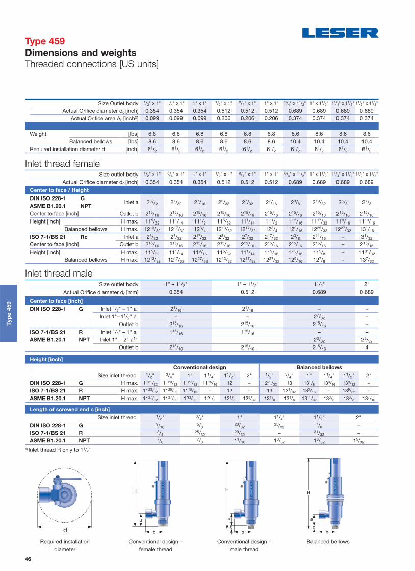
Height [mm]
Conventional design Balanced bellows
Size inlet thread 1/2" 3/4" 1" 11/4" 11/2" 2" 1/2" 3/4" 1" 11/4" 11/2" 2"
DIN ISO 228-1 G H max. 296 298 301 303 305 – 328 330 333 335 337 –ISO 7-1/BS 21 R H max. 298 299 303 – 305 – 330 331 335 – 337 –ASME B1.20.1 NPT H max. 301 301 307 308 308 309 333 333 339 340 340 341
Size Outlet body 1/2" x 1" 3/4" x 1" 1" x 1" 1/2" x 1" 3/4" x 1" 1" x 1" 3/4" x 11/2" 1" x 11/2" 11/4" x 11/2" 11/2" x 11/2"
Actual Orifice diameter d0 [mm] 9 9 9 13 13 13 17.5 17.5 17.5 17.5Actual Orifi ce area A0 [mm2] 63.6 63.6 63.6 133 133 133 241 241 241 241
Weight [kg] 3.1 3.1 3.1 3.1 3.1 3.1 3.9 3.9 3.9 3.9
Balanced bellows [kg] 3.9 3.9 3.9 3.9 3.9 4.7 4.7 4.7 4.7 4.7 Required installation diameter d [mm] 165 165 165 165 165 165 165 165 165 165
Inlet thread female Size outlet body 1/2" x 1" 3/4" x 1" 1" x 1" 1/2" x 1" 3/4" x 1" 1" x 1" 3/4" x 11/2" 1" x 11/2" 11/4" x 11/2" 11/2" x 11/2"
Actual Orifice diameter d0 [mm] 9 9 9 13 13 13 17.5 17.5 17.5 17.5
Center to face / Height
DIN ISO 228-1 GInlet a 53 56 62 53 56 62 60 66 67 73
ASME B1.20.1 NPT
Center to face [mm] Outlet b 75 75 75 75 75 75 75 75 75 75Height [mm] H max 283 286 292 283 286 292 287 293 294 300
Balanced bellows H max 315 318 324 315 318 324 319 325 326 332ISO 7-1/BS 21 Rc Inlet a 53 56 64 53 56 64 60 68 – 77Center to face [mm] Outlet b 75 75 75 75 75 75 75 75 – 75Height [mm] H max 283 286 294 283 286 294 287 295 – 304
Balanced bellows H max 315 318 326 315 318 326 319 327 – 336
Length of screwed end c [mm]
Size inlet thread 1/2" 3/4" 1" 11/4" 11/2" 2"DIN ISO 228-1 G 14 16 18 20 22 –ISO 7-1/BS 21 R 19 20 23 – 25 –ASME B1.20.1 NPT 22 22 27 28 28 29
1) Inlet thread R only up to 11/2“.
Required installation diameter
Conventional design – female thread
Conventional design – male thread
Balanced bellows
d c c
Typ
e 4
59
Inlet thread male Size outlet body 1" – 11/2" 1" – 11/2" 11/2" 2"
Actual Orifice diameter d0 [mm] 9 13 17.5 17.5
Center to face [mm]
DIN ISO 228-1 G Inlet 1/2" – 1" a 52 52 – –Inlet 1"– 11/2" a – – 56 –
Outlet b 75 75 75 –ISO 7-1/BS 21 R Inlet 1/2" – 1" a 49 49 – –ASME B1.20.1 NPT Inlet 1" – 2" a1) – – 53 53
Outlet b 75 75 75 100
Type 459
Dimensions and weights
Threaded connections [Metric units]
46
Height [inch]
Conventional design Balanced bellows
Size inlet thread 1/2" 3/4" 1" 11/4" 11/2" 2" 1/2" 3/4" 1" 11/4" 11/2" 2"
DIN ISO 228-1 G H max. 1121/32 1123/32 1127/32 1115/16 12 – 1229/32 13 131/8 133/16 139/32 –
ISO 7-1/BS 21 R H max. 1123/32 1125/32 1115/16 – 12 – 13 131/32 133/16 – 139/32 –
ASME B1.20.1 NPT H max. 1127/32 1127/32 123/32 121/8 121/8 125/32 131/8 131/8 1311/32 133/8 133/8 137/16
Size Outlet body 1/2" x 1" 3/4" x 1" 1" x 1" 1/2" x 1" 3/4" x 1" 1" x 1" 3/4" x 11/2" 1" x 11/2" 11/4" x 11/2" 11/2" x 11/2"
Actual Orifice diameter d0 [inch] 0.354 0.354 0.354 0.512 0.512 0.512 0.689 0.689 0.689 0.689Actual Orifi ce area A0 [inch2] 0.099 0.099 0.099 0.206 0.206 0.206 0.374 0.374 0.374 0.374
Weight [lbs] 6.8 6.8 6.8 6.8 6.8 6.8 8.6 8.6 8.6 8.6
Balanced bellows [lbs] 8.6 8.6 8.6 8.6 8.6 8.6 10.4 10.4 10.4 10.4 Required installation diameter d [inch] 61/2 61/2 61/2 61/2 61/2 61/2 61/2 61/2 61/2 61/2
Inlet thread female Size outlet body 1/2" x 1" 3/4" x 1" 1" x 1" 1/2" x 1" 3/4" x 1" 1" x 1" 3/4" x 11/2" 1" x 11/2" 11/4" x 11/2" 11/2" x 11/2"
Actual Orifice diameter d0 [inch] 0.354 0.354 0.354 0.512 0.512 0.512 0.689 0.689 0.689 0.689
Center to face / Height
DIN ISO 228-1 GInlet a 23/32 27/32 27/16 23/32 27/32 27/16 23/8 219/32 25/8 27/8
ASME B1.20.1 NPT
Center to face [inch] Outlet b 215/16 215/16 215/16 215/16 215/16 215/16 215/16 215/16 215/16 215/16
Height [inch] H max. 115/32 111/14 111/2 115/32 111/14 111/2 115/16 1117/32 119/16 1113/16
Balanced bellows H max. 1213/32 1217/32 123/4 1213/32 1217/32 123/4 129/16 1225/32 1227/32 131/16
ISO 7-1/BS 21 Rc Inlet a 23/32 27/32 217/32 23/32 27/32 217/32 23/8 211/16 – 31/32
Center to face [inch] Outlet b 215/16 215/16 215/16 215/16 215/16 215/16 215/16 215/16 – 215/16
Height [inch] H max. 115/32 111/14 119/16 115/32 111/14 119/16 115/16 115/8 – 1131/32
Balanced bellows H max. 1213/32 1217/32 1227/32 1213/32 1217/32 1227/32 129/16 127/8 – 137/32
Length of screwed end c [inch]
Size inlet thread 1/2" 3/4" 1" 11/4" 11/2" 2"DIN ISO 228-1 G 9/16
5/823/32
25/327/8 –
ISO 7-1/BS 21 R 3/425/32
29/32 – 31/32 –ASME B1.20.1 NPT 7/8
7/8 11/16 13/32 13/32 15/32
1) Inlet thread R only to 11/2".
Required installation diameter
Conventional design – female thread
Conventional design – male thread
Balanced bellows
d c c
Typ
e 4
59
Inlet thread male Size outlet body 1" – 11/2" 1" – 11/2" 11/2" 2"
Actual Orifice diameter d0 [mm] 0.354 0.512 0.689 0.689
Center to face [inch]
DIN ISO 228-1 G Inlet 1/2" – 1" a 21/16 21/16 – –Inlet 1"– 11/2" a – – 27/32 –
Outlet b 215/16 215/16 215/16 –ISO 7-1/BS 21 R Inlet 1/2" – 1" a 115/16 115/16 – –ASME B1.20.1 NPT Inlet 1" – 2" a1) – – 23/32 23/32
Outlet b 215/16 215/16 215/16 4
Type 459
Dimensions and weights
Threaded connections [US units]

47
Conventional design Balanced bellows
Actual Orifice diameter d0 [mm] 9 13 17.5 9 13 17.5Actual Orifi ce area A0 [mm2] 63.6 133 241 63.6 133 241
DIN EN 1092-1 (Available fl ange sizes refer to page 09/07)
Flange rating PN 40 – PN 400
Center to face [mm] Inlet a 100 100 105 100 100 105
Outlet b 100 100 100 100 100 100
Height [mm] H max. 330 330 333 375 375 378
ASME B 16.5 (Available fl ange sizes refer to page 09/07)
Flange rating class 150 – 2500
Center to face [mm] Inlet a 100 100 105 100 100 105
Outlet b 100 100 100 100 100 100
Height [mm] H max. 330 330 333 375 375 378
Note The outlet dimension b can differ at special combinations of nominal diameter and pressure range if fl anged connections are used at the inlet and outlet.Special dimensions are possible. More information at [email protected].
Weight
For the calculation of the total weight please use the Formular: WT = WN + WF (Inlet) + WF (Outlet)Weight net [kg]
3.1 3.1 3.9 4.3 4.3 5.1(without inlet and outlet fl ange) mN
Flange dimensions
DIN EN 1092-1 / Flange rating PN ASME B16.5 / Flange rating
Size 40 100 160 250 320 400 Size 150 300 600 900 1500 2500
DN 15 NPS 1/2"
Flange thickness [mm] s 18 – 22 28 28 30 14 18 18 26 26 30.2
Weight slip on fl ange [kg] mF 0.8 – 1.2 2.5 2.5 3.6 0.6 0.9 0.9 2.1 2.1 3
DN 20 NPS 3/4"
Flange thickness [mm] s 20 22 – – – – 15 18 18 25.4 25.4 32
Weight slip on fl ange [kg] mF 1.1 1.3 – – – – 0.8 1.4 1.4 2.3 2.3 3.5
DN 25 NPS 1"
Flange thickness [mm] s 22 – 26 30 36 40 17 21.5 21.5 32.5 32.5 40
Weight slip on fl ange [kg] mF 1.3 – 2.6 3.5 5 7.5 1 2.1 2.1 4.1 4.1 5.1
DN 40 NPS 11/2"
Flange thickness [mm] s 21 – 23 32 – – 22 24 24 32 – –
Weight slip on fl ange [kg] mF 2.1 – 2.9 4.3 – – 1.4 2.2 2.2 3.9 – –
Balanced bellowsConventional design
Typ
e 4
59
Type 459
Dimensions and weights
Flanged connections [Metric units]
48
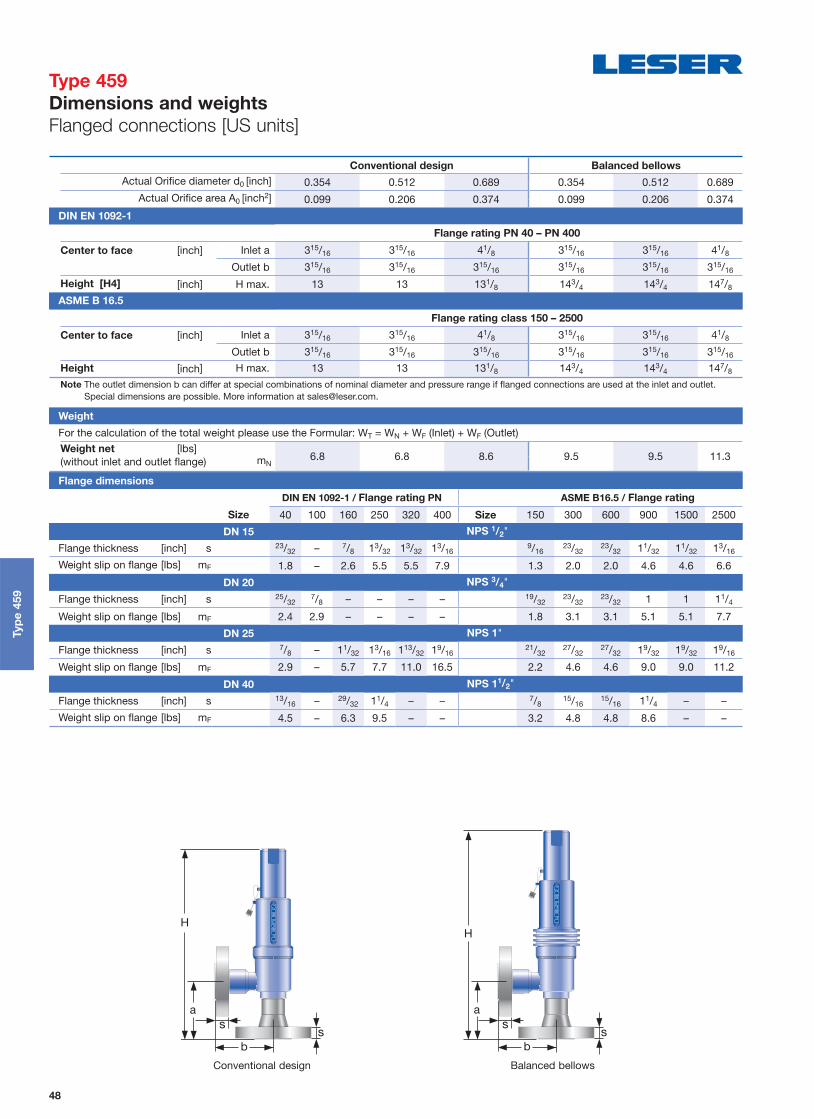
Conventional design Balanced bellows
Actual Orifice diameter d0 [inch] 0.354 0.512 0.689 0.354 0.512 0.689Actual Orifi ce area A0 [inch2] 0.099 0.206 0.374 0.099 0.206 0.374
DIN EN 1092-1
Flange rating PN 40 – PN 400
Center to face [inch] Inlet a 315/16 315/16 41/8 315/16 315/16 41/8
Outlet b 315/16 315/16 315/16 315/16 315/16 315/16
Height [H4] [inch] H max. 13 13 131/8 143/4 143/4 147/8
ASME B 16.5
Flange rating class 150 – 2500
Center to face [inch] Inlet a 315/16 315/16 41/8 315/16 315/16 41/8
Outlet b 315/16 315/16 315/16 315/16 315/16 315/16
Height [inch] H max. 13 13 131/8 143/4 143/4 147/8
Note The outlet dimension b can differ at special combinations of nominal diameter and pressure range if fl anged connections are used at the inlet and outlet.Special dimensions are possible. More information at [email protected].
Weight
For the calculation of the total weight please use the Formular: WT = WN + WF (Inlet) + WF (Outlet)Weight net [lbs]
6.8 6.8 8.6 9.5 9.5 11.3(without inlet and outlet fl ange) mN
Flange dimensions
DIN EN 1092-1 / Flange rating PN ASME B16.5 / Flange rating
Size 40 100 160 250 320 400 Size 150 300 600 900 1500 2500
DN 15 NPS 1/2"
Flange thickness [inch] s 23/32 – 7/8 13/32 13/32 13/169/16
23/3223/32 11/32 11/32 13/16
Weight slip on fl ange [lbs] mF 1.8 – 2.6 5.5 5.5 7.9 1.3 2.0 2.0 4.6 4.6 6.6
DN 20 NPS 3/4"
Flange thickness [inch] s 25/327/8 – – – – 19/32
23/3223/32 1 1 11/4
Weight slip on fl ange [lbs] mF 2.4 2.9 – – – – 1.8 3.1 3.1 5.1 5.1 7.7
DN 25 NPS 1"
Flange thickness [inch] s 7/8 – 11/32 13/16 113/32 19/1621/32
27/3227/32 19/32 19/32 19/16
Weight slip on fl ange [lbs] mF 2.9 – 5.7 7.7 11.0 16.5 2.2 4.6 4.6 9.0 9.0 11.2
DN 40 NPS 11/2"
Flange thickness [inch] s 13/16 – 29/32 11/4 – – 7/815/16
15/16 11/4 – –
Weight slip on fl ange [lbs] mF 4.5 – 6.3 9.5 – – 3.2 4.8 4.8 8.6 – –
Balanced bellowsConventional design
Typ
e 4
59
Type 459
Dimensions and weights
Flanged connections [US units]

49
Actual Orifi ce diameter d0 [mm] 9 13 17.5Actual Orifi ce Area A0 [mm2] 63.6 133 241
Body material: 1.4104 (430) Type 4593
Base / Connection size 1/2" 3/4" 1" 1/2" 3/4" 1" 3/4" 1" 11/4" 11/2" 2" Inlet Body Pressure rating PN 400 PN 250 PN 160Outlet body Pressure rating PN 40 PN 40 PN 40
Minimum p [barg] S/G/L 1.5 0.2 0.2 set pressure
Min. set pressure
standard bellows p [barg] S/G/L 3 3 3
Min. set pressure5)
high press. bellows p [barg] S/G/L 40 40 40
Maximum p [barg] S/G/L 250 200 100set pressure
Temperature min. [°C ] -10acc. to DIN EN max. [°C ] +300
Temperature min. [°C ] -29acc. to ASME max. [°C ] +300
Body material: 1.4404 (316L) Type 4592
Base / Connection size 1/2" 3/4" 1" 1/2" 3/4" 1" 3/4" 1" 11/4" 11/2" 2"Inlet Body
Pressure ratingPN 250
PN 500 (Option code L20)PN 160
PN 250 (Option code L20)PN 160
Outlet Body Pressure rating PN 160 PN 160 PN 160 Minimum p [barg] S/G/L 1.5 0.2 0.2
set pressure
Min. set pressure
standard bellows p [barg] S/G/L 3 3 3
Min. set pressure5)
high press. bellowsp [barg] S/G/L 40 40 40
Maximum p [barg] S/G/L 250 200 100set pressure
Temperature min. [°C ] -851)
acc. to DIN EN max. [°C ] +4502)
Temperature min. [°C ] -29acc. to ASME max. [°C ] +427
Body material: 1.4404 (316L) Type 4594
Base / Connection size 1/2" 3/4" 1" 1/2" 3/4" 1" 3/4" 1" 11/4" 11/2" 2"Inlet Body
Pressure ratingPN 250
PN 500 (Option code L20)PN 160
PN 250 (Option code L20)PN 160
Outlet Body Pressure rating PN 160 PN 160 PN 160
Minimum p [barg] S/G/L 1.5 0.2 0.2 set pressure
Min. set pressure
standard bellows p [barg] S/G/L 3 3 3
Min. set pressure5)
high press. bellowsp [barg] S/G/L 40 40 40
Maximum p [barg] S/G/L 250 200 100set pressure
Temperature min. [°C ] -2733)
acc. to DIN EN max. [°C ] +4002)
Temperature min. [°C ] -196acc. to ASME max. [°C ] +4502) 4)
Typ
e 4
59
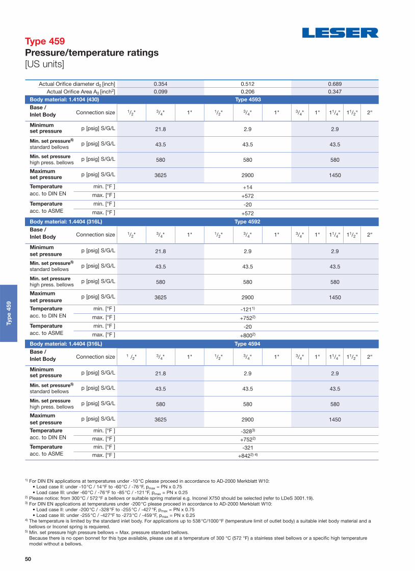
1) For DIN EN applications at temperatures under -10°C please proceed in accordance to AD-2000 Merkblatt W10:• Load case II: under -10°C / 14°F to -60°C / -76°F, pmax = PN x 0.75 • Load case III: under -60°C / -76°F to -85°C / -121°F, pmax = PN x 0.25
2) Please notice: from 300°C / 572°F a bellows or suitable spring material e.g. Inconel X750 should be selected (refer to LDeS 3001.19).3) For DIN EN applications at temperatures under -200°C please proceed in accordance to AD-2000 Merkblatt W10:
• Load case II: under -200°C / -328°F to -255°C / -427°F, pmax = PN x 0.75 • Load case III: under -255°C / -427°F to -273°C / -459°F, pmax = PN x 0.25
4) The temperature is limited by the standard inlet body. For applications up to 538°C/1000°F (temperature limit of outlet body) a suitable inlet body material and a bellows or Inconel spring is requiered.
5) Min. set pressure high pressure bellows = Max. pressure standard bellows.Because there is no open bonnet for this type available, please use at a temperature of 300 °C (572 °F) a stainless steel bellows or a specific high temperature model without a bellows.
Type 459
Pressure/temperature ratings
[Metric units]
50
Actual Orifi ce diameter d0 [inch] 0.354 0.512 0.689Actual Orifi ce Area A0 [inch2] 0.099 0.206 0.347
Body material: 1.4104 (430) Type 4593
Base / Connection size 1/2" 3/4" 1" 1/2" 3/4" 1" 3/4" 1" 11/4" 11/2" 2"Inlet Body
Minimum p [psig] S/G/L 21.8 2.9 2.9set pressure
Min. set pressure5)
standard bellows p [psig] S/G/L 43.5 43.5 43.5
Min. set pressure
high press. bellows p [psig] S/G/L 580 580 580
Maximum p [psig] S/G/L 3625 2900 1450set pressure
Temperature min. [°F ] +14acc. to DIN EN max. [°F ] +572
Temperature min. [°F ] -20acc. to ASME max. [°F ] +572
Body material: 1.4404 (316L) Type 4592
Base / Connection size 1/2" 3/4" 1" 1/2" 3/4" 1" 3/4" 1" 11/4" 11/2" 2"Inlet Body
Minimum p [psig] S/G/L 21.8 2.9 2.9set pressure
Min. set pressure5)
standard bellows p [psig] S/G/L 43.5 43.5 43.5
Min. set pressure
high press. bellowsp [psig] S/G/L 580 580 580
Maximum p [psig] S/G/L 3625 2900 1450set pressure
Temperature min. [°F ] -1211)
acc. to DIN EN max. [°F ] +7522)
Temperature min. [°F ] -20acc. to ASME max. [°F ] +8002)
Body material: 1.4404 (316L) Type 4594
Base / Connection size 1 /2" 3/4" 1" 1/2" 3/4" 1" 3/4" 1" 11/4" 11/2" 2"Inlet Body
Minimum p [psig] S/G/L 21.8 2.9 2.9set pressure
Min. set pressure5)
standard bellows p [psig] S/G/L 43.5 43.5 43.5
Min. set pressure
high press. bellowsp [psig] S/G/L 580 580 580
Maximum p [psig] S/G/L 3625 2900 1450set pressure
Temperature min. [°F ] -3283)
acc. to DIN EN max. [°F ] +7522)
Temperature min. [°F ] -321acc. to ASME max. [°F ] +8422) 4)
1) For DIN EN applications at temperatures under -10°C please proceed in accordance to AD-2000 Merkblatt W10:• Load case II: under -10°C / 14°F to -60°C / -76°F, pmax = PN x 0.75 • Load case III: under -60°C / -76°F to -85°C / -121°F, pmax = PN x 0.25
2) Please notice: from 300°C / 572°F a bellows or suitable spring material e.g. Inconel X750 should be selected (refer to LDeS 3001.19).3) For DIN EN applications at temperatures under -200°C please proceed in accordance to AD-2000 Merkblatt W10:
• Load case II: under -200°C / -328°F to -255°C / -427°F, pmax = PN x 0.75 • Load case III: under -255°C / -427°F to -273°C / -459°F, pmax = PN x 0.25
4) The temperature is limited by the standard inlet body. For applications up to 538°C/1000°F (temperature limit of outlet body) a suitable inlet body material and a bellows or Inconel spring is requiered.
5) Min. set pressure high pressure bellows = Max. pressure standard bellows.Because there is no open bonnet for this type available, please use at a temperature of 300 °C (572 °F) a stainless steel bellows or a specific high temperature model without a bellows.
Typ
e 4
59
Type 459
Pressure/temperature ratings
[US units]

51
Actual Orifi ce diameter d0 [mm] 9 13 17.5 Actual Orifi ce area A0 [mm2] 63.6 133 241
Actual Orifi ce diameter d0 [inch] 0.354 0.512 0.689 Actual Orifi ce area A0 [inch2] 0.099 0.206 0.374
Europe Coefficient of discharge Kdr
PED / DIN EN ISO 4126-1Approval No. 072021409Z0022/15/D/0135
S/G 0.83 0.81 0.79
L 0.61 0.53 0.52
Germany Coefficient of discharge w
PED / AD 2000-Merkblatt A2Approval No. TÜV SV 909
S/G 0.83 0.81 0.79
L 0.61 0.53 0.52
United States Coefficient of discharge K
ASME Sec. VIII Div. 1
Approval No. M 37112
S/G 0.811
Approval No. M 37101
L 0.566 Canada Coefficient of discharge K
CRNApproval No. The current approval no. can be found at www.leser.com
S/G 0.811
L 0.566
China Coefficient of discharge w
AQSIQApproval No. The current approval no. can be found at www.leser.com
S/G 0.83 0.81 0.79
L 0.61 0.53 0.52 Eurasian Custom Union Coefficient of discharge w
EAC
Approval No. The current approval no. can be found at www.leser.com
S/G 0.83 0.81 0.79
L 0.61 0.53 0.52 Classification societies Homepage
Bureau Veritas BV www.bureauveritas.comThe valid certification number is changed with every reneval.
A sample certificate including the valid certification number can be found at www.leser.com
DNV GL www.dnvgl.com
Lloyd‘s Register EMEA LREMEA www.lr.org
Registro Italiano Navale RINA www.rina.org
U.S. Coast Guard U.S.C.G www.uscg.orgTyp
e 4
59
Type 459
Approvals

52
Type 459 HDD
Cap H2
Type 459 HDD
Cap H2
Contents Page
Designs 53
Materials 54
Article numbers 55
Dimensions and weights
• Threaded connections 56
• Flanged connections 58
Pressure / temperature ratings 60
Approvals 61
Typ
e 4
59
HD
D
Type 459 HDD
Safety Relief Valves
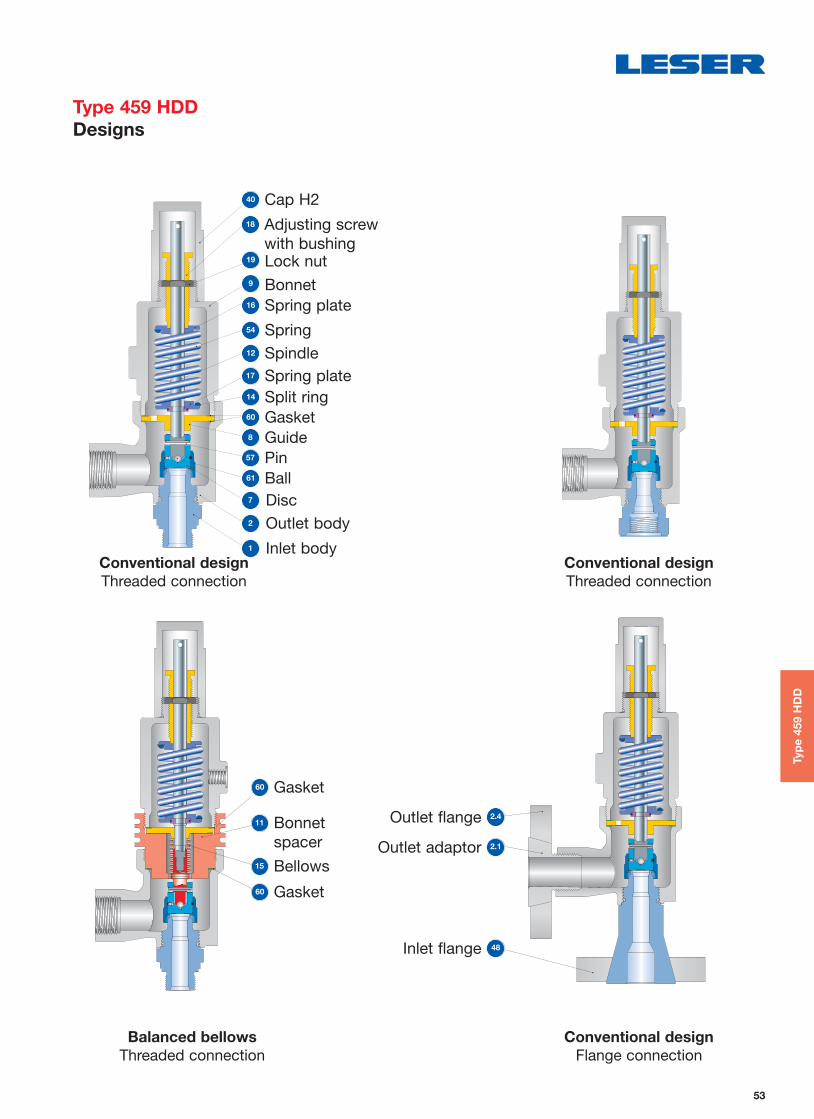
53
Typ
e 4
59
HD
D
Type 459 HDD
Designs
Balanced bellows
Threaded connectionConventional design
Flange connection
18 Adjusting screw with bushing
40 Cap H2
19 Lock nut
12 Spindle
54 Spring
8 Guide
61 Ball
1 Inlet body
9 Bonnet
17 Spring plate14 Split ring60 Gasket
57 Pin
2 Outlet body
7 Disc
16 Spring plate
Outlet flange 2.4
Outlet adaptor 2.1
Inlet flange 48
11 Bonnet spacer
60 Gasket
15 Bellows
Conventional design
Threaded connectionConventional design
Threaded connection
60 Gasket

54
Item Component Design Type 4594 HDD
1 Base / Inlet body
Threaded connection
1.4404 stellitedSA 479 316L stellited
Flange connection1.4404 stellited
SA 479 316L stellited
2 Outlet body 1.4408CF8M
2.1 Outlet adaptor Flange connection1.4404316L
2.4 Outlet fl ange Flange connection1.4404316L
7 Disc Metal seat1.4404 stellited
SA 479 316L stellited
8 Guide
1.4404316L
Balanced bellows design
1.4404 / SA 316LUpper connection of balanced bellows
9 Bonnet
1.4408CF8M
Balanced bellows design
1.4408CF8M
11 Bonnet spacerBalanced
bellows design1.4404316L
12 Spindle
1.4404316L
Balanced bellows design
1.4404316L
14 Split ring 1.4404316L
15 BellowsBalanced
bellows design1.4571316Ti
16/17 Spring plate1.4404316L
18Adjusting screw with
bushung1.4404 / PTFE316L / PTFE
19 Lock nut1.4404316L
40 Cap H21.4404316L
48 Inlet fl ange Flange connection1.4404316L
54 Spring Standard1.4310
Stainless steel
57 Pin1.4310
Stainless steel
60 GasketGraphite / 1.4301Graphite / 316L
61 Ball1.4401
316
Please notice:
• Modifications reserved by LESER.• LESER can upgrade materials without notice.• Every part can be replaced by other material acc. to customer specification. • The materials shall meet the requirements of the relevant regulations (Pressure Equipment Directive (PED), acc. to PED applied harmonized standards, AD
2000-Merkblätter, VdTÜV (Werkstoffblätter) as well as further materials listed in Section 8 of the Type-Examination.
Typ
e 4
59
HD
D
Type 459 HDD
Materials

55
Actual Orifi ce diameter d0 [mm] 61) 9
Actual Orifi ce area A0 [mm2] 28.3 63.9
Actual Orifi ce diameter d0 [inch] 0.236 0.354
Actual Orifi ce area A0 [inch2] 0.044 0.099 Body material: 14404 (316L)
Outlet body
Bonnet
1.4408
CF8M
1.4404
1.4408
H2 Art. No. 4594. 2132 2142
H4 Art. No. 4594. 2134 2144
p [barg]S/G/L
420.01 – 850 250.01 – 420
p [psig] 6091 – 12328 3626 – 6091
1) The specification of the medium is necessary at liquid applications (Option Code M09).
Metal seat
Typ
e 4
59
HD
D
Type 459 HDD
Article numbers

56
Height [mm]
Conventional design Balanced bellows
Size inlet thread 1/2" 3/4" 1" 1/2" 3/4" 1"DIN ISO 228-1 G H max. 296 298 301 328 330 333ISO 7-1/BS 21 R H max. 298 299 303 330 331 335ASME B1.20.1 NPT H max. 301 301 307 333 333 339
Length of screwed end c [mm]
Size inlet thread 1/2" 3/4" 1"DIN ISO 228-1 G 14 16 18ISO 7-1/BS 21 R 19 20 23ASME B1.20.1 NPT 22 22 27
Size Outlet body ½" x 1" ¾" x 1" 1" x 1" ½" x 1" ¾" x 1" 1" x 1"Actual Orifice diameter d0 [mm] 6 6 6 9 9 9
Actual Orifi ce area A0 [mm2] 28.3 28.3 28.3 63.6 63.6 63.6
Weight [kg] 3.1 3.1 3.1 3.1 3.1 3.1Balanced bellows [kg] 3.9 3.9 3.9 3.9 3.9 3.9
Required installation diameter d [mm] 165 165 165 165 165 165
Inlet thread female
Size outlet body ½" x 1" ¾" x 1" 1" x 1" ½" x 1" ¾" x 1" 1" x 1"Actual Orifice diameter d0 [mm] 6 6 6 9 9 9
Center to face / Height
DIN ISO 228-1 GInlet a 53 53 62*) 53 56 62
ASME B1.20.1 NPT
Center to face [mm] Outlet b 75 75 75*) 75 75 75Height [mm] H max. 283 286 292*) 283 286 292
Balanced bellows H max. 315 318 342*) 315 318 324ISO 7-1/BS 21 Rc Inlet a 53 56 64 53 56 64Center to face [mm] Outlet b 75 75 75 75 75 75Height [mm] H max. 283 286 294 283 286 294
Balanced bellows H max. 315 318 326 315 318 326
Inlet thread male
Size outlet body 1" 1"Actual Orifice diameter d0 [mm] 6 9
Center to face [mm]
DIN ISO 228-1 G Inlet a 52 52Outlet b 75 75
ISO 7-1/BS 21 R Inlet a 49 49ASME B1.20.1 NPT Outlet b 75 75
*) DIN ISO 228-1 G not possible.
Typ
e 4
59
HD
D
Required installation diameter
Conventional design – female thread
Conventional design – male thread
Balanced bellows
d c c
Type 459 HDD
Dimensions and weights
Threaded connections [Metric units]

57
Height [inch]
Conventional design Balanced bellows
Size inlet thread 1/2" 3/4" 1" 1/2" 3/4" 1"DIN ISO 228-1 G H max. 1121/32 1123/32 1127/32 1229/32 13 131/8
ISO 7-1/BS 21 R H max. 1123/32 1125/32 1115/16 13 131/32 133/16
ASME B1.20.1 NPT H max. 1127/32 1127/32 123/32 131/8 131/8 1311/32
Length of screwed end c [inch]
Size inlet thread 1/2" 3/4" 1"DIN ISO 228-1 G 9/16
5/823/32
ISO 7-1/BS 21 R 3/425/32
29/32
ASME B1.20.1 NPT 7/87/8 11/16
Size Outlet body ½" x 1" ¾" x 1" 1" x 1" ½" x 1" ¾" x 1" 1" x 1"Actual Orifice diameter d0 [inch] 0.236 0.236 0.236 0.354 0.354 0.354
Actual Orifi ce area A0 [inch2] 0.044 0.044 0.044 0.099 0.099 0.099
Weight [lbs] 6.8 6.8 6.8 6.8 6.8 6.8Balanced bellows [lbs] 8.6 8.6 8.6 8.6 8.6 8.6
Required installation diameter d [inch] 61/2 61/2 61/2 61/2 61/2 61/2
Inlet thread female
Size outlet body ½" x 1" ¾" x 1" 1" x 1" ½" x 1" ¾" x 1" 1" x 1"Actual Orifice diameter d0 [inch] 0.236 0.236 0.236 0.354 0.354 0.354
Center to face / Height
DIN ISO 228-1 GInlet a 23/32 27/32 27/16*) 23/32 27/32 27/16
ASME B1.20.1 NPT
Center to face [inch] Outlet b 215/16 215/16 215/16*) 215/16 215/16 215/16
Height [inch] H max. 115/32 111/14 111/2*) 115/32 111/14 111/2
Balanced bellows H max. 1213/32 1217/32 123/4*) 1213/32 1217/32 123/4
ISO 7-1/BS 21 Rc Inlet a 23/32 27/32 217/32 23/32 27/32 217/32
Center to face [inch] Outlet b 215/16 215/16 215/16 215/16 215/16 215/16
Height [inch] H max. 115/32 111/14 119/16 115/32 111/14 119/16
Balanced bellows H max. 1213/32 1217/32 1227/32 1213/32 1217/32 1227/32
Inlet thread male
Size outlet body 1" 1"Actual Orifice diameter d0 [inch] 1/4
11/32
Center to face [inch]
DIN ISO 228-1 G Inlet a 21/16 21/16
Outlet b 215/16 215/16
ISO 7-1/BS 21 R Inlet a 115/16 115/16
ASME B1.20.1 NPT Outlet b 215/16 215/16
*) DIN ISO 228-1 G not possible.
Typ
e 4
59
HD
D
Required installation diameter
Conventional design – female thread
Conventional design – male thread
Balanced bellows
d c c
Type 459 HDD
Dimensions and weights
Threaded connections [US units]

58
Conventional design Balanced bellows
Actual Orifice diameter d0 [mm] 6 9 6 9Actual Orifi ce area A0 [mm2] 28.3 63.6 28.3 63.6
DIN EN 1092-1 (Available fl ange sizes refer to page 09/07)
Flange rating PN 40 – PN 400
Center to face [mm] Inleta 100 100 100 100
Outlet b 100 100 100 100
Height [mm] H max. 330 330 375 375
ASME B 16.5 (Available fl ange sizes refer to page 09/07)
Flange rating class 150 – 2500
Center to face [mm] Inlet a 100 100 100 100
Outlet b 100 100 100 100
Height [mm] H max. 330 330 375 375
Note The outlet dimension b can differ at special combinations of nominal diameter and pressure range if fl anged connections are used at the inlet and outlet.Special dimensions are possible. More information at [email protected].
Weight
For the calculation of the total weight please use the Formular: WT = WN + WF (Inlet) + WF (Outlet)Weight net [kg]
3.1 3.1 4.3 4.3(without inlet and outlet fl ange) mN
Flange dimensions
DIN EN 1092-1 / Flange rating PN DIN ISO 1092-1 / Flange rating class
Size 40 100 160 250 320 400 Size 150 300 600 900 1500 2500
DN 15 NPS 1/2"
Flange thickness [mm] s 18 – 22 28 28 30 14 18 18 26 26 30.2
Weight slip on fl ange [kg] mF 0.8 – 1.2 2.5 2.5 3.6 0.6 0.9 0.9 2.1 2.1 3
DN 20 NPS 3/4"
Flange thickness [mm] s 20 22 – – – – 15 18 18 25.4 25.4 32
Weight slip on fl ange [kg] mF 1.1 1.3 – – – – 0.8 1.4 1.4 2.3 2.3 3.5
DN 25 NPS 1"
Flange thickness [mm] s 22 – 26 30 36 40 17 21.5 21.5 32.5 32.5 40
Weight slip on fl ange [kg] mF 1.3 – 2.6 3.5 5 7.5 1 2.1 2.1 4.1 4.1 5.1
DN 40 NPS 11/2"
Flange thickness [mm] s 21 – 23 32 – – 22 24 24 32 – –
Weight slip on fl ange [kg] mF 2.1 – 2.9 4.3 – – 1.4 2.2 2.2 3.9 – –
Typ
e 4
59
HD
D
Balanced bellowsConventional design
Type 459 HDD
Dimensions and weights
Flanged connections [Metric units]

59
Conventional design Balanced bellows
Actual Orifice diameter d0 [inch] 0.236 0.354 0.236 0.354Actual Orifi ce area A0 [inch2] 0.044 0.099 0.044 0.099
DIN EN 1092-1 (Available fl ange sizes refer to page 09/07)
Flange rating PN 40 – PN 400
Center to face [inch] Inlet a 315/16 315/16 315/16 315/16
Outlet b 315/16 315/16 315/16 315/16
Height [inch] H max. 13 13 143/4 143/4
ASME B 16.5 (Available fl ange sizes refer to page 09/07)
Flange rating class 150 – 2500
Center to face [inch] Inlet a 315/16 315/16 315/16 315/16
Outlet b 315/16 315/16 315/16 315/16
Height [inch] H max. 13 13 143/4 143/4
Note The outlet dimension b can differ at special combinations of nominal diameter and pressure range if fl anged connections are used at the inlet and outlet.Special dimensions are possible. More information at [email protected].
Weight
For the calculation of the total weight please use the Formular: WT = WN + WF (Inlet) + WF (Outlet)Weight net [lbs]
6.8 6.8 9.5 9.5(without inlet and outlet fl ange) mN
Flange dimensions
DIN EN 1092-1 / Flange rating PN ASME B16.5 / Flange rating class
Size 40 100 160 250 320 400 Size 150 300 600 900 1500 2500
DN 15 NPS 1/2"
Flange thickness [mm] s 23/32 – 7/8 13/32 13/32 13/169/16
23/3223/32 11/32 11/32 13/16
Weight slip on fl ange [kg] mF 1.8 – 2.6 5.5 5.5 7.9 1.3 2 2 4.6 4.6 6.6
DN 20 NPS 3/4"
Flange thickness [mm] s 25/327/8 – – – – 19/32
23/3223/32 1 1 11/4
Weight slip on fl ange [kg] mF 2.4 2.9 – – – – 1.8 3.1 3.1 5.1 5.1 7.7
DN 25 NPS 1"
Flange thickness [mm] s 7/8 – 11/32 13/16 13/32 19/1621/32
27/3227/32 19/32 19/32 19/16
Weight slip on fl ange [kg] mF 2.9 – 5.7 7.7 11 16.5 2.2 4.6 4.6 9 9 11.2
DN 40 NPS 11/2"
Flange thickness [mm] s 13/16 – 29/32 11/4 – – 7/815/16
15/16 11/4 – –
Weight slip on fl ange [kg] mF 4.5 – 6.3 9.5 – – 3.2 4.8 4.8 8.6 – –
Typ
e 4
59
HD
D
Balanced bellowsConventional design
Type 459 HDD
Dimensions and weights
Flanged connections [US units]

60
Metric units
Actual Orifi ce diameter d0 [mm] 6 9
Actual Orifi ce Area A0 [mm2] 28.3 63.6
Body material 1.4404 (316L) Type 4594
Base / Connection size 1/2" 3/4" 1" 1/2" 3/4" 1"Inlet Body Pressure rating PN 850 PN 500
Outlet body Pressure rating PN 160 PN 160 Minimum
p [barg] S/G/L 420 250.01set pressure
Maximum p [barg] S/G 850420 set pressure p [barg] L –
Temperature min. [°C ] -2731) -2731)
acc. to DIN EN max. [°C ] +4002) +4002)
Temperature min. [°C ] -196 -196acc. to ASME max. [°C ] +4503) +4503)
US units
Actual Orifi ce diameter d0 [inch] 0.236 0.354
Actual Orifi ce Area A0 [inch2] 0.044 0.099
Body material 1.4404 (316L) Type 4594
Base / Connection size 1/2" 3/4" 1" 1/2" 3/4" 1"Inlet Body
Minimum p [psig] S/G/L 6091 3625set pressure
Maximum p [psig] S/G 123286091set pressure p [psig] L –
Temperature min. [°F ] -4591) -4591)
acc. to DIN EN max. [°F ] +7522) +7522)
Temperature min. [°F ] -321 -321acc. to ASME max. [°F ] +8423) +8423)
1) For DIN EN applications at temperatures under -200°C / -328°F please proceed in accordance to AD-2000 Merkblatt W10.• Load case II: under -200°C / -328°F to -255°C / -427°F, pmax = PN x 0.75
• Load case III: under -255°C / -427°F to -273°C / -459°F, pmax = PN x 0.252) Please notice: from 300°C / 572°F, a bellows or suitable spring material e.g. Inconel X750 should be selected (refer to LDeS 3001.19). For the temperature range
>400°C / >752°F an outlet body material e.g. 1.4552 or 1.4581 (special casting) is required.3) The temperature is limited by the standard inlet body. For applications up to 538°C/1000°F (temperature limit of outlet body) a suitable inlet body material and a
bellows or Inconel spring is requiered.
Typ
e 4
59
HD
D
Type 459 HDD
Pressure/temperature ratings
[Metric units + US units]

61
Actual Orifi ce diameter d0 [mm] 6 9 Actual Orifi ce area A0 [mm2] 28.3 63.6
Actual Orifi ce diameter d0 [inch] 0.236 0.354 Actual Orifi ce area A0 [inch2] 0.044 0.099
Europe Coefficient of discharge Kdr
PED / DIN EN ISO 4126-1Approval No. 072021409Z0022/15/D/0135
S/G 0.81 0.83
L 0.70 0.61
Germany Coefficient of discharge w
PED / AD 2000-Merkblatt A2Approval No. TÜV SV 909
S/G 0.81 0.83
L 0.70 0.61
United States Coefficient of discharge K
ASME Sec. VIII Div. 1
Approval No. M 37112
S/G 0.811Approval No. M 37112
L 0.566 Canada Coefficient of discharge K
CRNApproval No. The current approval no. can be found at www.leser.com
S/G 0.811
L 0.566 China Coefficient of discharge w
AQSIQApproval No. The current approval no. can be found at www.leser.com
S/G 0.81 0.83
L 0.70 0.61 Eurasian Custom Union Coefficient of discharge w
EAC
Approval No. The current approval no. can be found at www.leser.com
S/G 0.81 0.83
L 0.70 0.61 Classification societies Homepage
Bureau Veritas BV www.bureauveritas.com The valid certification number is changed with every reneval.
A sample certificate including the valid certifi-cation number can be found at www.leser.com
DNV GL www.dnvgl.com
Lloyd‘s Register EMEA LREMEA www.lr.org
Registro Italiano Navale RINA www.rina.org
U.S. Coast Guard U.S.C.G www.uscg.org
Typ
e 4
59
HD
D
Type 459 HDD
Approvals

62
Type 462
Plain lever H3
Contents Page
Designs 63
Materials 64
Article numbers 65
Dimensions and weights
• Threaded connections 66
• Flanged connections 68
Pressure / temperature ratings 70
Approvals 72
Type 462
Cap H2
Type 462
Refrigeration
technology
Typ
e 4
62
Type 462
Safety Relief Valves

63
Outlet adaptor 2.1
Outlet flange 2.4
Inlet flange 48
Conventional design
Flange connection
18 Adjusting screw with bushing
40 Cap H2
19 Lock nut
12 Spindle
54 Spring
8 Guide
61 Ball
1 Inlet body
9 Bonnet
17 Spring plate14 Split ring60 Gasket
57 Pin
2 Outlet body
7 O-ring disc
16 Spring plate
Conventional design
Threaded connectionConventional design
Threaded connection
Balanced bellows
Threaded connection
60 Gasket
11 Bonnetspacer
60 Gasket
15 Bellows Typ
e 4
62
Type 462
Designs

64
Item Component Design Type 4623 Type 4622 Type 4624
1 Base / Inlet body
Threadedconnection
1.41041), 1.4404 1.4404 1.4404 SA 479 4301), SA 479 316L SA 479 316L SA 479 316L
Flange connection 1.4404 1.4404 1.4404SA 479 316L SA 479 316L SA 479 316L
2 Outlet body 1.0619 1.0619 1.4408 WCB WCB CF8M
2.1 Outlet adaptor Flange connection 1.4404 1.4404 1.4404316L 316L 316L
2.4 Outlet fl ange Flange connection 1.4404 1.4404 1.4404316L 316L 316L
7 O-ring disc 1.4404 1.4404 1.4404SA 479 316L SA 479 316L SA 479 316L
7.4 Soft seal O-ring
“N”2) NBR NBR NBRNitrile-Butadiene Nitrile-Butadiene Nitrile-Butadiene
“K”2) CR CR CRChloroprene Chloroprene Chloroprene
“D”2) EPDM EPDM EPDMEthylen-Propylene-Diene Ethylen-Propylene-Diene Ethylen-Propylene-Diene
“L”2) FKM FKM FKM Fluorocarbon Fluorocarbon Fluorocarbon
“C”3) FFKM FFKM FFKMPerfl uor Perfl uor Perfl uor
8 Guide
1.4104 tenifer 1.4104 tenifer 1.4404Chrome steel tenifer Chrome steel tenifer 316L
Balanced bellows design
1.4404 / SA 316L 1.4404 / SA 316L 1.4404 / SA 316LUpper connection of balanced bellows Upper connection of balanced bellows Upper connection of balanced bellows
9 Bonnet
0.7043 1.0619 1.4408Ductile Gr. 60-40-18 WCB CF8M
Balanced bellows design
1.0619 1.0619 1.4408 WCB WCB CF8M
11 Bonnet spacerBalanced
bellows design1.4404 1.4404 1.4404316L 316L 316L
12 Spindle
1.4021 1.4404 1.4404420 316L 316L
Balanced bellows design
1.4404 1.4404 1.4404316L 316L 316L
14 Split ring 1.4104 1.4104 1.4404Chrome steel Chrome steel 316L
15 BellowsBalanced
bellows design1.4571 1.4571 1.4571316Ti 316Ti 316Ti
16/17 Spring plate 1.0718 1.0718 1.4404Steel Steel 316L
18Adjusting screw
with bushing1.4104 / PTFE 1.4104 / PTFE 1.4104 / PTFE
Chrome steel / PTFE Chrome steel / PTFE Chrome steel / PTFE
19 Lock nut 1.4104 1.4104 1.4404430 430 316L
40 Cap H2 1.0460 1.0460 1.4404SA 105 SA 105 316L
48 Inlet fl ange Flange connection 1.4404 1.4404 1.4404316L 316L 316L
54 SpringStandard 1.1200 / 1.8159 / 1.7107 1.1200 / 1.8159 / 1.7107 1.4310
Carbon steel Carbon steel Stainless steel
Optional 1.4310 1.4310 –Stainless steel Stainless steel –
57 Pin 1.4310 1.4310 1.4310Stainless steel Stainless steel Stainless steel
60 Gasket Graphite / 1.4401 Graphite / 1.4401 Graphite / 1.4401Graphite / 316 Graphite / 316 Graphite / 316
61 Ball 1.3541 1.3541 1.4401Hardened stainless steel Hardened stainless steel 316
Please notice:
• Modifications reserved by LESER. If several materials are specified LESER defines the material.• LESER can upgrade materials without notice.• Every part can be replaced by other material acc. to customer specification. • The materials shall meet the requirements of the relevant regulations (Pressure Equipment Directive (PED), acc. to PED applied harmonized standards, AD
2000-Merkblätter, VdTÜV (Werkstoffblätter) as well as further materials listed in Section 8 of the Type-Examination.
1) only valid for male thread DIN ISO 228-1 G¾ G1, G1½ (Option codes V55, V56, V57) (please note availability regarding d0)2) d0 9 + 13: O-ring 90 Shore for set pressure > 100 bar3) d0 9 + 13: O-ring 90 Shore for set pressure > 40 bar
Typ
e 4
62
Type 462
Materials

65
Type 462
Actual Orifi ce diameter d0 [mm] 9 13 17.5
Actual Orifi ce area A0 [mm2] 63.6 133 241
Actual Orifi ce diameter d0 [inch] 0.354 0.512 0.689
Actual Orifi ce area A0 [inch2] 0.099 0.206 0.374
O-ring material NBR “N” J302)
CR “K” J212)
EPDM “D” J222)
FKM “L” J232)
FFKM “C” J203)
Outlet body casted
Inlet body 1.4104 H2 Art. No. 4623. 2902 2912 2922
Outlet body1.0619
WCBH3 Art. No. 4623. 2903 2913 2923
Bonnet 0.7043 H4 Art. No. 4623. 2904 2914 2924
p [barg]S/G/L
0.5 – 2501) 0.5 – 1801) 0.5 – 92.51)
p [psig] 7.3 – 36251) 7.3 – 26101) 7.3 – 13421)
Outlet body investment casted
Inlet body 1.4404 H2 Art. No. 4622. 3772 3782 3792
Outlet body 1.0619
WCBH3 Art. No. 4622. 3773 3783 3793
Bonnet 1.0619 H4 Art. No. 4622. 3774 3784 3794
p [barg]S/G/L
0.5 – 250 0.5 – 180 0.5 – 92.5
p [psig] 7.3 – 3625 7.3 – 2610 7.3 – 1342
Outlet body investment casted
Inlet body 1.4404
H2 Art. No. 4624. 2192 2202 2212Outlet body
1.4408
CF8M
Bonnet 1.4408 H4 Art. No. 4624. 2194 2204 2214
p [barg]S/G/L
0.5 – 250 0.5 – 180 0.5 – 92.5
p [psig] 7.3 – 3625 7.3 – 2610 7.3 – 1342
Type 462 Refrigeration technologyDNE 15, 20 15, 20, 25 25
DNA 20 25 32
Actual Orifi ce diameter d0 [mm] 13 13 17,5
Actual Orifi ce area A0 [mm2] 133 133 241
Weight [kg] 3.1 3.1 3.9
O-ring material NBR “N” J30
CR “K” J21
EPDM “D” J22
Outlet body investment casted
Inlet + Outlet PN 40
Inlet body 1.4404 H2 Art. No. 4622. 3882 3982 3892
Outlet body1.0619
WCB
Bonnet 1.0619
p [barg] D/G/F 0,5 – 40 40 40
Also all other LESER valve types can be designed for refrigeration technology.
1) Max. set pressure 69 bar / 1000 psig for Type 4623 acc. to ASME-Code Sec. VIII, Div. 1 with UV-Stamp.The design of Type 4623 is permitted with limitations acc. to ASME-Code Sec. VIII, Div. 1, UCD-2, UCD-3. Type 4623 shall not be used for lethal substances, irrespective of their state of aggregation.
2) d0 9 + 13: O-ring 90 Shore for set pressure > 100 bar3) d0 9 + 13: O-ring 90 Shore for set pressure > 40 bar
Typ
e 4
62
Type 462
Article numbers

66
Height [mm]
Conventional design Balanced bellows
Size inlet thread 1/2" 3/4" 1" 11/4" 11/2" 2" 1/2" 3/4" 1" 11/4" 11/2" 2"
DIN ISO 228-1 G H max. 296 298 301 303 305 – 328 330 333 335 337 –ISO 7-1/BS 21 R H max. 298 299 303 – 305 – 330 331 335 – 337 –ASME B1.20.1 NPT H max. 301 301 307 307 308 309 333 333 339 340 340 341
Size Outlet body 1/2" x 1" 3/4" x 1" 1" x 1" 1/2" x 1" 3/4" x 1" 1" x 1" 3/4" x 11/2" 1" x 11/2" 11/4" x 11/2" 11/2" x 11/2"
Actual Orifice diameter d0 [mm] 9 9 9 13 13 13 17.5 17.5 17.5 17.5Actual Orifi ce area A0 [mm2] 63.6 63.6 63.6 133 133 133 241 241 241 241
Weight [kg] 3.1 3.1 3.1 3.1 3.1 3.1 3.9 3.9 3.9 3.9
Balanced bellows [kg] 3.9 3.9 3.9 3.9 3.9 3.9 4.7 4.7 4.7 4.7 Required installation diameter d [mm] 165 165 165 165 165 165 165 165 165 165
Inlet thread femaleSize Outlet body 1/2" x 1" 3/4" x 1" 1" x 1" 1/2" x 1" 3/4" x 1" 1" x 1" 3/4" x 11/2" 1" x 11/2" 11/4" x 11/2" 11/2" x 11/2"
Actual Orifice diameter d0 [mm] 9 9 9 13 13 13 17.5 17.5 17.5 17.5 Center to face / Height
DIN ISO 228-1 GInlet a 53 56 62 53 56 62 60 66 67 73
ASME B1.20.1 NPT
Center to face [mm] Outlet b 75 75 75 75 75 75 75 75 75 75Height [mm] H max. 283 286 292 283 286 292 287 293 294 300
Balanced bellows H max. 315 318 324 315 318 324 319 325 326 332ISO 7-1/BS 21 Rc Inlet a 53 56 64 53 56 64 60 68 – 77Center to face [mm] Outlet b 75 75 75 75 75 75 75 75 – 75Height [mm] H max. 283 286 294 283 286 294 287 295 – 304
Balanced bellows H max. 315 318 326 315 318 326 319 327 – 336
Length of screwed end c [mm]
Size inlet thread 1/2" 3/" 1" 11/4" 11/2" 2"DIN ISO 228-1 G 14 16 18 20 22 24ISO 7-1/BS 21 R 19 20 23 25 25 –ASME B1.20.1 NPT 22 22 27 28 28 29
1) Inlet thread R only up to 11/2".
Required installation diameter
Conventional design – Female thread
Conventional design – Male thread
Balanced bellows
dc c
Typ
e 4
62
Inlet thread male Size outlet body 1" – 11/2" 1" – 11/2" 11/2" 2"
Actual Orifice diameter d0 [mm] 9 13 17.5 17.5
Center to face [mm]
DIN ISO 228-1 G Inlet 1/2" – 1" a 52 52 – –Inlet 1"– 11/2" a – – 56 –
Outlet b 75 75 75 –ISO 7-1/BS 21 R Inlet 1/2" – 1" a 49 49 – –ASME B1.20.1 NPT Inlet 1" – 2" a1) – – 53 53
Outlet b 75 75 75 100
Type 462
Dimensions and weights
Threaded connections [Metric units]

67
Height [inch]
Conventional design Balanced bellows
Size inlet thread 1/2" 3/4" 1" 11/4" 11/2" 2" 1/2" 3/4" 1" 11/4" 11/2" 2"
DIN ISO 228-1 G H max. 1121/32 1123/32 1127/32 1115/16 12 – 1229/32 13 131/8 133/16 139/32 –ISO 7-1/BS 21 R H max. 1123/32 1125/32 1115/16 – 12 – 13 131/32 133/16 – 139/32 –ASME B1.20.1 NPT H max. 1127/32 1127/32 123/32 121/8 121/8 125/32 131/8 131/8 1311/32 133/8 133/8 137/16
Size Outlet body 1/2" x 1" 3/4" x 1" 1" x 1" 1/2" x 1" 3/4" x 1" 1" x 1" 3/4" x 11/2" 1" x 11/2" 11/4" x 11/2" 11/2" x 11/2"
Actual Orifice diameter d0 [inch] 0.354 0.354 0.354 0.512 0.512 0.512 0.689 0.689 0.689 0.689Actual Orifi ce area A0 [inch2] 0.099 0.099 0.099 0.206 0.206 0.206 0.374 0.374 0.374 0.374
Weight [lbs] 6.8 6.8 6.8 6.8 6.8 6.8 8.6 8.6 8.6 8.6
Balanced bellows [lbs] 8.6 8.6 8.6 8.6 8.6 8.6 10.4 10.4 10.4 10.4 Required installation diameter d [inch] 61/2 61/2 61/2 61/2 61/2 61/2 61/2 61/2 61/2 61/2
Inlet thread femaleSize Outlet body 1/2" x 1" 3/4" x 1" 1" x 1" 1/2" x 1" 3/4" x 1" 1" x 1" 3/4" x 11/2" 1" x 11/2" 11/4" x 11/2" 11/2" x 11/2"
Actual Orifice diameter d0 [inch] 0.354 0.354 0.354 0.512 0.512 0.512 0.689 0.689 0.689 0.689 Center to face / Height
DIN ISO 228-1 GInlet a 23/32 27/32 27/16 23/32 27/32 27/16 23/8 219/32 25/8 27/8
ASME B1.20.1 NPT
Center to face [inch] Outlet b 215/16 215/16 215/16 215/16 215/16 215/16 215/16 215/16 215/16 215/16
Height [inch] H max. 115/32 111/14 111/2 115/32 111/4 111/2 115/16 1117/32 119/16 1113/16
Balanced bellows H max. 1213/32 1217/32 123/4 1213/32 1217/32 123/4 129/16 1225/32 1227/32 131/16
ISO 7-1/BS 21 Rc Inlet a 23/32 27/32 217/32 23/32 27/32 217/32 23/8 211/16 – 31/32
Center to face [inch] Outlet b 215/16 215/16 215/16 215/16 215/16 215/16 215/16 215/16 – 215/16
Height [inch] H max. 115/32 111/14 119/16 115/32 111/14 119/16 115/16 115/8 – 1131/32
Balanced bellows H max. 1213/32 1217/32 1227/32 1213/32 1217/32 1227/32 129/16 127/8 – 137/32
Length of screwed end c [inch]
Size inlet thread 1/2" 3/" 1" 11/4" 11/2" 2"DIN ISO 228-1 G 9/16
5/823/32
25/327/8
15/16
ISO 7-1/BS 21 R 3/425/32
29/3231/32
31/32 –ASME B1.20.1 NPT 7/8
7/8 11/16 13/32 13/32 15/32
1) Inlet thread R only up to 11/2".
Required installation diameter
Conventional design – Female thread
Conventional design – Male thread
Balanced bellows
dc c
Typ
e 4
62
Inlet thread male Size outlet body 1" – 11/2" 1" – 11/2" 11/2" 2"
Actual Orifice diameter d0 [mm] 0.354 0.512 0.689 0.689
Center to face [inch]
DIN ISO 228-1 G Inlet 1/2" – 1" a 21/16 21/16 – –Inlet 1"– 11/2" a – – 27/32 –
Outlet b 215/16 215/16 215/16 –ISO 7-1/BS 21 R Inlet 1/2" – 1" a 115/16 115/16 – –ASME B1.20.1 NPT Inlet 1" – 2" a1) – – 23/32 23/32
Outlet b 215/16 215/16 215/16 4
Type 462
Dimensions and weights
Threaded connections [US units]

68
Conventional design Balanced bellows
Actual Orifice diameter d0 [mm] 9 13 17.5 9 13 17.5Actual Orifi ce area A0 [mm2] 63.6 133 241 63.6 133 241
DIN EN 1092-1
Flange rating PN 40 – 400
Center to face [mm] Inlet a 100 100 105 100 100 105
Outlet b 100 100 100 100 100 100
Height [mm] H max. 330 330 333 375 375 378
ASME B 16.5
Flange rating class 150 – 2500
Center to face [mm] Inlet a 100 100 105 100 100 105
Outlet b 100 100 100 100 100 100
Height [mm] H max. 330 330 333 375 375 378
Note The outlet dimension b can differ at special combinations of nominal diameter and pressure range if fl anged connections are used at the inlet and outlet.Special dimensions are possible. More information at [email protected].
Weight
For the calculation of the total weight please use the Formular: WT = WN + WF (Inlet) + WF (Outlet)Weight net [kg]
3.1 3.1 3.5 4.3 4.3 4.7(without inlet and outlet fl ange) mN
Flange dimensions
DIN EN 1092-1 / Flange rating PN ASME B16.5 / Flange rating class
Size 40 100 160 250 320 400 Size 150 300 600 900 1500 2500
DN 15 NPS 1/2"
Flange thickness [mm] s 18 – 22 28 28 30 14 18 18 26 26 30.2
Weight slip on fl ange [kg] mF 0.8 – 1.2 2.5 2.5 3.6 0.6 0.9 0.9 2.1 2.1 3
DN 20 NPS 3/4"
Flange thickness [mm] s 20 22 – – – – 15 18 18 25.4 25.4 32
Weight slip on fl ange [kg] mF 1.1 1.3 – – – – 0.8 1.4 1.4 2.3 2.3 3.5
DN 25 NPS 1"
Flange thickness [mm] s 22 – 26 30 36 40 17 21.5 21.5 32.5 32.5 40
Weight slip on fl ange [kg] mF 1.3 – 2.6 3.5 5 7.5 1 2.1 2.1 4.1 4.1 5.1
DN 40 NPS 11/2"
Flange thickness [mm] s 21 – 23 32 – – 22 24 24 32 – –
Weight slip on fl ange [kg] mF 2.1 – 2.9 4.3 – – 1.4 2.2 2.2 3.9 – –
Balanced bellowsConventional design
Typ
e 4
62
Type 462
Dimensions and weights
Flanged connections [Metric units]

69
Conventional design Balanced bellows
Actual Orifice diameter d0 [inch] 0.354 0.512 0.689 0.354 0.512 0.689Actual Orifi ce area A0 [inch2] 0.099 0.206 0.374 0.099 0.206 0.374
DIN EN 1092-1
Flange rating PN 40 – 400
Center to face [inch] Inlet a 315/16 315/16 41/8 315/16 315/16 41/8
Outlet b 315/16 315/16 315/16 315/16 315/16 315/16
Height [inch] H max. 13 13 131/8 143/4 143/4 147/8
ASME B 16.5
Flange rating class 150 – 2500
Center to face [inch] Inlet a 315/16 315/16 41/8 315/16 315/16 41/8
Outlet b 315/16 315/16 315/16 315/16 315/16 315/16
Height [inch] H max. 13 13 131/8 143/4 143/4 147/8
Note The outlet dimension b can differ at special combinations of nominal diameter and pressure range if fl anged connections are used at the inlet and outlet.Special dimensions are possible. More information at [email protected].
Weight
For the calculation of the total weight please use the Formular: WT = WN + WF (Inlet) + WF (Outlet)Weight net [lbs]
6.8 6.8 7.7 9.5 9.5 10.4(without inlet and outlet fl ange) mN
Flange dimensions
DIN EN 1092-1 / Flange rating PN ASME B16.5 / Flange rating class
Size 40 100 160 250 320 400 Size 150 300 600 900 1500 2500
DN 15 NPS 1/2"
Flange thickness [mm] s 23/32 – 7/8 13/32 13/32 13/169/16
23/3223/32 11/32 11/32 13/16
Weight slip on fl ange [lbs] mF 1.8 – 2.6 5.5 5.5 7.9 1.3 2.0 2.0 4.6 4.6 6.6
DN 20 NPS 3/4"
Flange thickness [mm] s 25/327/8 – – – – 19/32
23/3223/32 1 1 11/4
Weight slip on fl ange [lbs] mF 2.4 2.9 – – – – 1.8 3.1 3.1 5.1 5.1 7.7
DN 25 NPS 1"
Flange thickness [mm] s 7/8 – 11/32 13/16 13/32 19/1621/32
27/3227/32 19/32 19/32 19/16
Weight slip on fl ange [lbs] mF 2.9 – 5.7 7.7 11.0 16.5 2.2 4.6 4.6 9.0 9.0 11.2
DN 40 NPS 11/2"
Flange thickness [mm] s 13/16 – 29/32 11/4 – – 7/815/16
15/16 11/4 – –
Weight slip on fl ange [lbs] mF 4.5 – 6.3 9.5 – – 3.2 4.8 4.8 8.6 – –
Balanced bellowsConventional design
Typ
e 4
62
Type 462
Dimensions and weights
Flanged connections [US units]

70
Actual Orifi ce diameter d0 [mm] 9 13 17.5
Actual Orifi ce Area A0 [mm2] 63.6 133 241 Body material: 1.4104 (430F) Type 4623
Base / Connection size 1/2" 3/4" 1" 1/2" 3/4" 1" 3/4" 1" 11/4" 11/2" 2" Inlet Body Pressure rating PN 400 PN 250 PN 160
Outlet body Pressure rating PN 40 PN 40 PN 40 Minimum
p [barg] S/G/L 0.5 0.5 0.5 set pressure
Min. set pressure
standard bellowsp [barg] S/G/L 3 3 3
Min. set pressure1)
high press. bellowsp [barg] S/G/L 40 40 40
Maximum p [barg] S/G/L 250 180 92.5set pressure
Temperature min. [°C ] -102)
acc. to DIN EN3) max. [°C ] +150
Temperature min. [°C ] -29acc. to ASME3)
max. [°C ] +150 Body material: 1.4404 (316L) Type 4622
Base / Connection size 1/2" 3/4" 1" 1/2" 3/4" 1" 3/4" 1" 11/4" 11/2" 2"Inlet Body Pressure rating PN 250 PN 160 PN 160
Outlet Body Pressure rating PN 160 PN 160 PN 160 Minimum
p [barg] S/G/L 0.5 0.5 0.5 set pressure
Min. set pressure
standard bellows p [barg] S/G/L 3 3 3
Min. set pressure1)
high press. bellowsp [barg] S/G/L 40 40 40
Maximum p [barg] S/G/L 250 180 92.5set pressure
Temperature min. [°C ] -45acc. to DIN EN3)
max. [°C ] +150Temperature min. [°C ] -29acc. to ASME3)
max. [°C ] +150 Body material: 1.4404 (316L) Type 4624
Base / Connection size 1/2" 3/4" 1" 1/2" 3/4" 1" 3/4" 1" 11/4" 11/2" 2"Inlet Body Pressure rating PN 250 PN 160 PN 160
Outlet Body Pressure rating PN 160 PN 160 PN 160
Minimump [barg] S/G/L 0.5 0.5 0.5
set pressure
Min. set pressure
standard bellows p [barg] S/G/L 3 3 3
Min. set pressure1)
high press. bellowsp [barg] S/G/L 40 40 40
Maximum p [barg] S/G/L 250 180 92.5
set pressure
Temperature min. [°C ] -45acc. to DIN EN3) max. [°C ] +150Temperature min. [°C ] -45acc. to ASME3) max. [°C ] +150
1) Min. set pressure high pressure bellows = Max. pressure standard bellows.2) For DIN EN applications at temperatures under -10°C please proceed according to AD 2000-Merkblatt W10. 3) The temperature is limited by the soft seal material. The stated values are valid for EPDM.
Typ
e 4
62
Type 462
Pressure/temperature ratings
Metric units

71
Actual Orifi ce diameter d0 [inch] 0.354 0.512 0.689
Actual Orifi ce Area A0 [inch2] 0.099 0.206 0.374 Body material: 1.4104 (430F) Type 4623
Base /
Inlet bodyConnection size 1/2" 3/4" 1" 1/2" 3/4" 1" 3/4" 1" 11/4" 11/2" 2"
Minimum p [psig] S/G/L 7.3 7.3 7.3set pressure
Min. set pressure
standard bellows p [psig] S/G/L 43.5 43.5 43.5
Min. set pressure1)
high press. bellows p [psig] S/G/L 580 580 580
Maximum p [psig] S/G/L 3625 2610 1342set pressure
Temperature min. [°F ] +142)
acc. to DIN EN3) max. [°F ] +302 Temperature min. [°F ] -20
acc. to ASME3) max. [°F ] +302
Body material: 1.4404 (316L) Type 4622
Base /
Inlet bodyConnection size 1/2" 3/4" 1" 1/2" 3/4" 1" 3/4" 1" 11/4" 11/2" 2"
Minimump [psig] S/G/L 7.3 7.3 7.3
set pressure
Min. set pressure
standard bellows p [psig] S/G/L 43.5 43.5 43.5
Min. set pressure1)
high press. bellows p [psig] S/G/L 580 580 580
Maximum p [psig] S/G/L 3625 2610 1342set pressure
Temperature min. [°F ] -49acc. to DIN EN3)
max. [°F ] +302Temperature min. [°F ] -20acc. to ASME3)
max. [°F ] +302 Body material: 1.4404 (316L) Type 4624
Base /
Inlet bodyConnection size 1/2" 3/4" 1" 1/2" 3/4" 1" 3/4" 1" 11/4" 11/2" 2"
Minimump [psig] S/G/L 7.3 7.3 7.3
set pressure
Min. set pressure
standard bellowsp [psig] S/G/L 43.5 43.5 43.5
Min. set pressure1)
high press. bellowsp [psig] S/G/L 580 580 580
Maximump [psig] S/G/L 3625 2610 1342
set pressure
Temperature min. [°F ] -49acc. to DIN EN3)
max. [°F ] +302Temperature min. [°F ] -49acc. to ASME3)
max. [°F ] +302
1) Min. set pressure high pressure bellows = Max. pressure standard bellows.2) For DIN EN applications at temperatures under -10°C please proceed according to AD 2000-Merkblatt W10. 3) The temperature is limited by the soft seal material. The stated values are valid for EPDM.
Typ
e 4
62
Type 462
Pressure/temperature ratings
US units

72
Actual Orifi ce diameter d0 [mm] 9 13 17.5 Actual Orifi ce area A0 [mm2] 63.6 133 241
Actual Orifi ce diameter d0 [inch] 0.354 0.512 0.689 Actual Orifi ce area A0 [inch2] 0.099 0.206 0.374
Europe Coefficient of discharge Kdr
PED / DIN EN ISO 4126-1
Approval No. 072021409Z0022/15/D/0135
S/G 0.83 0.81 0.79
L 0.61 0.61 0.52
Germany Coefficient of discharge w
PED / AD 2000-Merkblatt A2
Approval No. TÜV SV 909
S/G 0.83 0.81 0.79
L 0.61 0.61 0.52
United States Coefficient of discharge K
ASME Sec. VIII Div. 1
Approval No. M 37112
S/G 0.811
Approval No. M 37101
L 0.566
Canada Coefficient of discharge K
CRN
Approval No. The current approval no. can be found at www.leser.com
S/G 0.811
L 0.566
China Coefficient of discharge w
AQSIQ
Approval No. The current approval no. can be found at www.leser.com
S/G 0.83 0.81 0.79
L 0.61 0.61 0.52
Eurasian Custom Union Coefficient of discharge w
EAC
Approval No. The current approval no. can be found at www.leser.com
S/G 0.83 0.81 0.79
L 0.61 0.61 0.52
Classification societies Homepage
Bureau Veritas BV www.bureauveritas.comThe valid certification number is changed with every reneval.
A sample certificate including the valid certification number can be found at www.leser.com
DNV GL DNV www.dnvgl.com
Lloyd‘s Register EMEA LREMEA www.lr.org
Registro Italiano Navale RINA www.rina.org
U.S. Coast Guard U.S.C.G www.uscg.org
Typ
e 4
62
Type 462
Approvals
7373
Contents Page
Designs 74
Materials 75
Article numbers 76
Dimensions and weights
• Threaded connections 77
• Flanged connections 79
Pressure / temperature ratings 81
Approvals 82
Series 459
Available options 83
Available connections
• Threaded connections 84
• Flanged connections 85
LESER Original Spare Parts Kits 86
Type 462 HDD
Cap H2
Type 462 HDD
Cap H2
Typ
e 4
62 H
DD
Type 462 HDD
Safety Relief Valves

74
18 Adjusting screw with bushing
40 Cap H2
19 Lock nut
12 Spindle
54 Spring
7 O-ring disc
1 Inlet Body
16 Spring plate
2 Outlet body
9 Bonnet
17 Spring plate14 Split ring60 Gasket8 Guide57 Pin61 Ball
Conventional design
Threaded connection
Typ
e 4
62 H
DD
Conventional design
Threaded connection
Balanced bellows
Threaded connection
60 Gasket
11 Bonnetspacer
60 Gasket
15 Bellows
Type 462 HDD
Designs
Outlet adaptor 2.1
Outlet flange 2.4
Inlet flange 48
Conventional design
Flange connection

75
Item Component Design Type 4624 HDD
1 Base / Inlet body
Threadedconnection
1.4404SA 479 316L
Flange connection1.4404
SA 479 316L
2 Outlet body 1.4408CF8M
2.1 Outlet adaptor Flange connection1.4404316L
2.4 Outlet fl ange Flange connection1.4404316L
7 O-ring disc1.4404
SA 479 316L
7.4 Soft seal O-ring
“N”1) NBRNitrile-Butadiene
“K”1) CRChloroprene
“D”1) EPDMEthylen-Propylene-Diene
“L”1) FKMFluorocarbon
“C”2) FFKMPerfl uor
8 Guide
1.4404316L
Balanced bellows design
1.4404 / SA 316LUpper conn. part of balanced bellows
9 Bonnet
1.4408CF8M
Balanced bellows design
1.4408CF8M
11 Bonnet spacerBalanced
bellows design1.4404316L
12 Spindle
1.4404316L
Balanced bellows design
1.4404316L
14 Split ring 1.4404316L
15 BellowsBalanced
bellows design1.4571316Ti
16/17 Spring plate1.4404316L
18Adjusting screw
with bushing1.4404 / PTFE316L / PTFE
19 Lock nut1.4404316L
40 Cap H21.4404316L
48 Inlet fl ange Flange connection1.4404316L
54 Spring Standard1.4310
Stainless steel
57 Pin1.4310
Stainless steel
60 GasketGraphite / 1.4301Graphite / 316L
61 Ball 1.4401316
Please notice:
• Modifications reserved by LESER.• LESER can upgrade materials without notice.• Every part can be replaced by other material acc. to customer specification. • The materials shall meet the requirements of the relevant regulations (Pressure Equipment Directive (PED), acc. to PED applied harmonized standards, AD
2000-Merkblätter, VdTÜV (Werkstoffblätter) as well as further materials listed in Section 8 of the Type-Examination.
1) O-ring 90 Shore for set pressures > 100 bar2) O-ring 90 Shore for set pressures > 40 bar
Typ
e 4
62 H
DD
Type 462 HDD
Materials

76
Actual Orifi ce diameter d0 [mm]
9
Actual Orifi ce area A0 [mm2]
63,9
Actual Orifi ce diameter d0 [inch] 0.354
Actual Orifi ce area A0 [inch2] 0.099
O-ring material NBR “N” J301)
CR “K” J211)
EPDM “D” J221)
FKM “L” J231)
FFKM “C” J202)
Body material: 1.4404 (316L)
Outlet body
Bonnet
1.4408
CF8M
1.4404
1.4408
H2 Art. No. 4624. 2152
H4 Art. No. 4624. 2154
p [barg]S/G/L
250.01 – 350
p [psig] 3625 – 5076
O-ring disc
Typ
e 4
62 H
DD
1) O-ring 90 Shore for set pressures > 100 bar2) O-ring 90 Shore for set pressures > 40 bar
Type 462 HDD
Article numbers

77
Size Outlet body 1/2" x 1" 3/4" x 1" 1" x 1"Actual Orifice diameter d0 [mm] 9 9 9
Actual Orifi ce area A0 [mm2] 63.6 63.6 63.6
Weight [kg] 3.1 3.1 3.1Balanced bellows [kg] 3.9 3.9 3.9
Required installation diameter d [mm] 165 165 165
Inlet thread female
Size Outlet body 1/2" x 1" 3/4" x 1" 1" x 1"Actual Orifice diameter d0 [mm] 9 9 9
Center to face / Height
DIN ISO 228-1 GInlet a 53 56 62
ASME B1.20.1 NPT
Center to face [mm] Outlet b 75 75 75Height [mm] H max. 283 286 292
Balanced bellows H max. 315 318 324ISO 7-1/BS 21 Rc Inlet a 53 56 64Center to face [mm] Outlet b 75 75 75Height [mm] H max. 283 286 294
Balanced bellows H max. 315 318 326
Inlet thread male
Size outlet body 1"Actual Orifice diameter d0 [mm] 9
Center to face [mm]
DIN ISO 228-1 GInlet a 52
Outlet b 75ISO 7-1/BS 21 R
Inlet a 49ASME B1.20.1 NPT
Outlet b 75
Height [mm]
Size inlet threadConventional design Balanced bellows
1/2" 3/4" 1" 1/2" 3/4" 1"DIN ISO 228-1 G H max. 296 298 301 328 330 333ISO 7-1/BS 21 R H max. 298 299 303 330 331 335ASME B1.20.1 NPT H max. 301 301 307 333 333 339
Length of screwed end c [mm]
Size inlet thread 1/2" 3/4" 1"DIN ISO 228-1 G 14 16 18ISO 7-1/BS 21 R 19 20 23ASME B1.20.1 NPT 22 22 27
Typ
e 4
62 H
DD
Required installation diameter
Conventional design – female thread
Conventional design – male thread
Balanced bellows
d c c
Type 462 HDD
Dimensions and weights
Threaded connections [Metric units]

78
Size Outlet body 1/2" x 1" 3/4" x 1" 1" x 1"Actual Orifice diameter d0 [inch] 0.354 0.354 0.354
Actual Orifi ce area A0 [inch2] 0.099 0.099 0.099
Weight [lbs] 6.8 6.8 6.8Balanced bellows [lbs] 8.6 8.6 8.6
Required installation diameter d [inch] 61/2 61/2 61/2
Inlet thread female
Size Outlet body 1/2" x 1" 3/4" x 1" 1" x 1"Actual Orifice diameter d0 [inch] 0.354 0.354 0.354
Center to face / Height
DIN ISO 228-1 GInlet a 23/32 27/32 27/16
ASME B1.20.1 NPT
Center to face [inch] Outlet b 215/16 215/16 215/16
Height [inch] H max. 115/32 111/14 111/2
Balanced bellows H max. 1213/32 1217/32 123/4
ISO 7-1/BS 21 Rc Inlet a 23/32 27/32 217/32
Center to face [inch] Outlet b 215/16 215/16 215/16
Height [inch] H max. 115/32 111/14 119/16
Balanced bellows H max. 1213/32 1217/32 1227/32
Inlet thread male
Size outlet body 1"Actual Orifice diameter d0 [inch] 0.354
Center to face [inch]
DIN ISO 228-1 GInlet a 21/16
Outlet b 215/16
ISO 7-1/BS 21 RInlet a 115/16
ASME B1.20.1 NPT
Outlet b 215/16
Height [inch]
Size inlet threadConventional design Balanced bellows
3/8" 1/2" 3/8" 1/2" 3/8" 1/2"DIN ISO 228-1 G H max. 1121/32 1123/32 1127/32 1229/32 13 131/8
ISO 7-1/BS 21 R H max. 1123/32 1125/32 1115/16 13 131/32 133/16
ASME B1.20.1 NPT H max. 1127/32 1127/32 123/32 131/8 131/8 1311/32
Length of screwed end “c” [inch]
Size inlet thread 1/2" 3/4" 1"DIN ISO 228-1 G 9/16
5/823/32
ISO 7-1/BS 21 R 3/425/32
29/32
ASME B1.20.1 NPT 7/87/8
11/16
Typ
e 4
62 H
DD
Required installation diameter
Conventional design – female thread
Conventional design – male thread
Balanced bellows
d c c
Type 462 HDD
Dimensions and weights
Threaded connections [US units]

79
Conventional design Balanced bellows
Actual Orifice diameter d0 [mm] 9 9Actual Orifi ce area A0 [mm2] 63.6 63.6
DIN EN 1092-1
Flange rating PN 40 – 400
Center to face [mm] Inlet a 100 100
Outlet b 100 100
Height [mm] H max. 330 375
ASME B 16.5
Flange rating class 150 – 2500
Center to face [mm] Inlet a 100 100
Outlet b 100 100
Height [mm] H max. 330 375
Note The outlet dimension b can differ at special combinations of nominal diameter and pressure range if fl anged connections are used at the inlet and outlet.Special dimensions are possible. More information at [email protected].
Weight
For the calculation of the total weight please use the Formular: WT = WN + WF (Inlet) + WF (Outlet)Weight net [kg]
3.1 4.3(without inlet and outlet fl ange) mN
Flange dimensions
DIN EN 1092-1 / Flange rating PN ASME B16.5 / Flange rating class
Size 40 100 160 250 320 400 Size 150 300 600 900 1500 2500
DN 15 NPS 1/2"
Flange thickness [mm] s 18 – 22 28 28 30 14 18 18 26 26 30.2Weight slip on fl ange [kg] mF 0.8 – 1.2 2.5 2.5 3.6 0.6 0.9 0.9 2.1 2.1 3
DN 20 NPS 3/4"
Flange thickness [mm] s 20 22 – – – – 15 18 18 25.4 25.4 32Weight slip on fl ange [kg] mF 1.1 1.3 – – – – 0.8 1.4 1.4 2.3 2.3 3.5
DN 25 NPS 1"
Flange thickness [mm] s 22 – 26 30 36 40 17 21.5 21.5 32.5 32.5 40Flange thickness [kg] mF 1.3 – 2.6 3.5 5 7.5 1 2.1 2.1 4.1 4.1 5.1
DN 40 NPS 11/2"
Flanschblattdicke [mm] s 21 – 23 32 – – 22 24 24 32 – –Weight slip on fl ange [kg] mF 2.1 – 2.9 4.3 – – 1.4 2.2 2.2 3.9 – –
Typ
e 4
62 H
DD
Balanced bellowsConventional design
Type 462 HDD
Dimensions and weights
Flanged connections [Metric units]
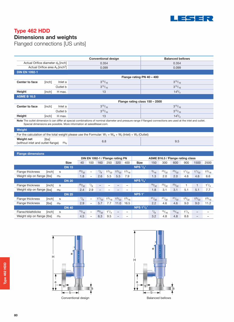
80
Conventional design Balanced bellows
Actual Orifice diameter d0 [inch] 0.354 0.354Actual Orifi ce area A0 [inch2] 0.099 0.099
DIN EN 1092-1
Flange rating PN 40 – 400
Center to face [inch] Inlet a 315/16 315/16
Outlet b 315/16 315/16
Height [inch] H max. 13 143/4
ASME B 16.5
Flange rating class 150 – 2500
Center to face [inch] Inlet a 315/16 315/16
Outlet b 315/16 315/16
Height [inch] H max. 13 143/4
Note The outlet dimension b can differ at special combinations of nominal diameter and pressure range if fl anged connections are used at the inlet and outlet.Special dimensions are possible. More information at [email protected].
Weight
For the calculation of the total weight please use the Formular: WT = WN + WF (Inlet) + WF (Outlet)Weight net [lbs]
6.8 9.5(without inlet and outlet fl ange) mN
Flange dimensions
DIN EN 1092-1 / Flange rating PN ASME B16.5 / Flange rating class
Size 40 100 160 250 320 400 Size 150 300 600 900 1500 2500
DN 15 NPS 1/2"
Flange thickness [inch] s 23/32 – 7/8 13/32 13/32 13/169/16
23/3223/32 11/32 11/32 13/16
Weight slip on fl ange [lbs] mF 1.8 – 2.6 5.5 5.5 7.9 1.3 2.0 2.0 4.6 4.6 6.6
DN 20 NPS 3/4"
Flange thickness [inch] s 25/327/8 – – – – 19/32
23/3223/32 1 1 11/4
Weight slip on fl ange [lbs] mF 2.4 2.9 – – – – 1.8 3.1 3.1 5.1 5.1 7.7
DN 25 NPS 1"
Flange thickness [inch] s 7/8 – 11/32 13/16 13/32 19/1621/32
27/3227/32 19/32 19/32 19/16
Flange thickness [lbs] mF 2.9 – 5.7 7.7 11.0 16.5 2.2 4.6 4.6 9.0 9.0 11.2DN 40 NPS 11/2"
Flanschblattdicke [inch] s 13/16 – 29/32 11/4 – – 7/815/16
15/16 11/4 – –Weight slip on fl ange [lbs] mF 4.5 – 6.3 9.5 – – 3.2 4.8 4.8 8.6 – –
Typ
e 4
62 H
DD
Balanced bellowsConventional design
Type 462 HDD
Dimensions and weights
Flanged connections [US units]

81
Metric unitsActual Orifi ce diameter d0 [mm] 9
Actual Orifi ce Area A0 [mm2] 63.6 Body material 1.4404 (316L) Type 4624
Base / Connection size 1/2" 3/4" 1"Inlet Body Pressure rating PN 500
Outlet body Pressure rating PN 160
Minimum p [barg] S/G/L 250.01set pressure
Maximump [barg] S/G/L 350set pressure
Temperature min. [°C ] -45acc. to DIN EN1)
max. [°C ] +150 Temperature min. [°C ] -45
acc. to ASME1) max. [°C ] +150
US unitsActual Orifi ce diameter d0 [inch] 0.354
Actual Orifi ce Area A0 [inch2] 0.099 Body material 1.4404 (316L) Type 4624
Base / Connection size 1/2" 3/4" 1"Inlet Body
Minimum p [psig] S/G/L 3625set pressure
Maximump [psig] S/G/L 5076set pressure
Temperature min. [°F ] -49acc. to DIN EN1)
max. [°F ] +302 Temperature min. [°F ] -49
acc. to ASME1) max. [°F ] +302
1) The temperature is limited by soft seal material. The stated values are valid for EPDM.
Typ
e 4
62 H
DD
Type 462 HDD
Pressure temperature ratings
[Metric units + US units]

82
Actual Orifi ce diameter d0 [mm] 9
Actual Orifi ce area A0 [mm2] 63.6
Actual Orifi ce diameter d0 [inch] 0.354
Actual Orifi ce area A0 [inch2] 0.099
Europe Coefficient of discharge Kdr
PED / DIN EN ISO 4126-1
Approval No. 072021409Z0022/15/D/0135
S/G 0.83
L 0.61
Germany Coefficient of discharge w
PED / AD 2000-Merkblatt A2
Approval No. TÜV SV 909
S/G 0.83
L 0.61
United States Coefficient of discharge K
ASME Sec. VIII Div. 1
Approval No. M 37112
S/G 0.811
Approval No. M 37101
L 0.566
Canada Coefficient of discharge K
CRN
Approval No. The current approval no. can be found at www.leser.com
S/G 0.811
L 0.566
China Coefficient of discharge w
AQSIQ
Approval No. The current approval no. can be found at www.leser.com
S/G 0.83
L 0.61
Eurasian Custom Union Coefficient of discharge w
EAC
Approval No. The current approval no. can be found at www.leser.com
S/G 0.83
L 0.61
Classification societies Homepage
Bureau Veritas BV www.bureauveritas.comThe valid certification number is changed with every reneval.
A sample certificate including the valid certification number can be found at www.leser.com
DNV GL www.dnvgl.com
Lloyd‘s Register EMEA LREMEA www.lr.org
Registro Italiano Navale RINA www.rina.org
U.S. Coast Guard U.S.C.G www.uscg.org
Typ
e 4
62 H
DD
Type 462 HDD
Approvals

83
Se
rie
s 4
59
Series 459
Available Options
CodeYYYY
CodeXXXX
CodeZZZZ
Type 459 Type 459 Type 462 Type 462
Male thread Female thread Flanged version
Stellited sealing surface
J25: Disc stellited L20: Base/inlet body
Disc with inserted
sealing plate
J44: PTFE-FDA “A” J48: PCTFE “G” J49: VESPEL-SP “T”
Soft seal o-ring disc
J30: NBR “N” J21: CR “K” J22: EPDM “D” J23: FKM “L” J20: FFKM “C”
Special material
O-ring-damper H4
J66
Heating jacket
H29
Lift indicator
J93: Lift indicator
Balanced bellows
Test gag
J69: H4 J70: H2
INCONEL X-750 spring
X08
O-ring-damper H2
J65
Solar valve
N80
4592.2482 4592.2484
Refrigeration technology
Art. No. see page 65

84
Actual Orifi ce diameter d0 [mm] 6 9 / 13 17.5
Actual Orifi ce area A0 [mm2] 28.3 63.9 / 133 241Actual Orifi ce diameter d0 [inch] 0.236 0.345 / 0.512 0.689
Actual Orifi ce area A0 [inch2] 0.044 0.099 / 0.206 0.374
Inlet Outlet Inlet Outlet Inlet Outlet
Male thread DIN ISO 228-1
G
1/2" V545) – V541) – – –3/4 " V555) – V55 – – –
1" V565) V56 V68 V56 –
11/4" – – – V83 –
11/2" – V69 – V69 V57 V69
Female thread DIN ISO 228-1
G
1/2" V505) – V50 – – –3/4 " V515) – V51 – V51 –
1" – V66 V522) V66 V52 –
11/4" – V81 – V81 V84 –
11/2" – V67 – V67 V53 V67
Male thread ISO 7-1/BS 21
R/BSPT
1/2" V303) 5) – V306) – – –3/4 " V315) – V31 – – –
1" V325) V32 V42 V32 –
11/2" – V43 – V43 V33 V43
Female thread ISO 7-1/BS 21
Rc/BSPT
1/2" V385) – V38 – – –3/4 " V395) – V39 – V39 –
1" V405) V40 V36 V40 –
11/2" – V37 – V37 V41 V37
Male thread ANSI/ASME B1.20.1
NPT
1/2" V615) – V614) – – –3/4 " V625) – V62 – – –
1" V635) V63 V73 V63 –
11/4" – – – V85 –
11/2" – V74 – V74 V64 V74
2" – – – – V86 –
Female thread ANSI/ASME B1.20.1
NPT
1/2" V585) – V58 – – –3/4 " V595) – V59 – V59 –
1" V605) V71 V60 V71 V60 –
11/4" – V80 – V80 V87 –
11/2" – V72 – V72 V75 V72
2" – – – – – V88
Flanged and threaded connections can be combined. Threads according to other standards are available. Please specify in writing (diameter, pressure rating, standard).
1) Only for d0 9 mm2) d0 9 mm: up to PN 4203) Only as special design4) d0 13 mm: up to 125 bar and 455 °C5) max. PN 700: For higher set pressures a special inlet body is required (see LDeS 3001.19)6) V30 d0 9 mm
Se
rie
s 4
59
Series 459
Available connections
Threaded connections

85
1) Caution! Only connecting dimensions correspond to PN 250, outlet body and bonnet are designed for PN 160.
ANSI/ASME B 16.5
NPS CL Inlet Outlet Inlet Outlet Inlet Outlet Inlet Outlet
1/2"
150 V01 – V01 – V01 – – –300 V02 – V02 – V02 – – –600 V02 – V02 – V02 – – –900 V03 – V03 – V03 – – –1500 V03 – V03 – V03 – – –2500 V04 – V04 – V04 – – –
3/4"
150 V05 – V05 – V05 – V05 –300 V06 – V06 – V06 – V06 –600 V06 – V06 – V06 – V06 –900 V07 – V07 – V07 – V07 –1500 V07 – V07 – V07 – V07 –2500 V08 – V08 – V08 – V08 –
1"
150 V09 – V09 V18 V09 V18 V09 –300 V10 V19 V10 V19 V10 V19 V10 –600 V10 V19 V10 V19 V10 V19 V10 –900 V11 – V11 – V11 – V11 –1500 V11 – V11 – V11 – V11 –2500 V12 – V12 – V12 – V12 –
11/2"
150 – – – V21 – V21 – V21300 – – – V22 – V22 – V22600 – – – V22 – V22 – V22
Nominal diameterPressure
ratingd0 6 mm d0 9 mm d0 13 mm d0 17.5 mm
DIN EN 1092-1
Option code Option code Option code Option code
DN PN Inlet Outlet Inlet Outlet Inlet Outlet Inlet Outlet
15
40 I21 – I21 – I21 – – –160 I22 – I22 – I22 – – –250 I23 – I23 – I23 – – –320 I24 – I24 – I24 – – –400 I25 – I25 – I25 – – –
2040 I26 – I26 – I26 – I26 –160 I27 – I27 – I27 – I27 –
25
40 I31 I46 I31 I46 I31 I46 I31 –160 I32 I47 I32 I47 I32 I47 I32 –250 I33 I482) I33 I481) I33 I481) I33 –320 I34 – I34 – I34 – I34 –400 I35 – I35 – I35 – I35 –
40
40 – – – I49 – I49 – I49160 – – – I50 – I50 – I50250 – – – I511) – I511) – I511)
Flanged and threaded connections can be combined. Flanges according to other standards, e. g. JIS are available. Please specify in writing (diameter, pressure rating and standard).
Type 462 Refrigeration technology – Flange facings DIN EN 1092, groove face D
Nominal diameterCenter to face
[mm]d0 13 mm d0 13 mm d0 17.5 mm
DIN EN 1092-1
DN a b Option code Option code Option code
Inlet Outlet Inlet Outlet Inlet Outlet Inlet Outlet Inlet Outlet
15 20 90 80 I1C I1J – – – –
20 20 90 80 I1D I1J – – – –15 25 100 100 – – I1A I1H – –15 25 95 95 – – I1F I1L – –20 25 90 80 – – I1D I1K – –20 25 95 95 – – I1G I51 – –25 25 100 100 – – I1B I1H – –25 25 90 80 – – I1E I1K – –25 32 100 100 – – – – I1B I1M
Se
rie
s 4
59
Series 459
Available connections
Flanged connections

86
Article numbers
d0 9 13 17,5
Art. No.
Type 459 5012. 1230 1231 1232
Contents − Type 459
Item Component Material Quantity
7 Disc 1.4404 / 316L 114 Split ring 1.4404 / 316L 2
40.3 Spacer 1.4571 / 316Ti 357 Pin 1.4310 / Stainless steel 159 Securing ring (split ring) 1.4571 / 316Ti 1
60 GasketGraphite / 1.4401
Graphite / 3162
61 Ball 1.4401 / 316 1
63 GasketGraphite / 1.4401
Graphite / 3161
The LESER Spare Parts Kits contain all the parts recommended for the regular maintenance of a LESER safety valve
Sp
are
Pa
rts K
its
Series 459
LESER Original Spare Parts Kits Type 459

87
Article numbers
d0 9 13 17,5
Art. No.
Type 462 5012. 1233 1234 1235
Type 462 HDD 5012. 1233 – –
The Compact Performance Type 462 Original Spare Parts Kit is equipped with four O-rings (Item 7.4) in the two most commonly used materials – FKM and EPDM – with different shore hardness. The correct O-ring should be selected depending on the set pressure.
Contents − Type 462, 462 HDD
Item Component Material Quantity
7.1 O-ring disc body 1.4404 / 316L 17.2 Lifting aid 1.4404 / 316L 1
7.4 O-ringFKM 70/75 Shore A, FKM 90 Shore A EPDM 70 Shore A, EPDM 90 Shore A
4
7.5 Pin 1.4310 / Stainless steel 114 Split ring 1.4404 / 316L 2
40.3 Spacer 1.4571 / 316Ti 357 Pin 1.4310 / Stainless steel 159 Securing ring (split ring) 1.4571 / 316Ti 1
60 GasketGraphite / 1.4401
Graphite / 3162
61 Ball 1.4401 / 316 1
63 Gasket Graphite / 1.4401Graphite / 316
1
The LESER Spare Parts Kits contain all the parts recommended for the regular maintenance of a LESER safety valve
Sp
are
Pa
rts K
its
Series 459
LESER Original Spare Parts Kits Type 462, 462 HDD

The-Safety-Valve.com
20537 Hamburg, Wendenstr. 133-135
20506 Hamburg, P.O. Box 26 16 51
Fon +49 (40) 251 65-100
Fax +49 (40) 251 65-500
LESER GmbH & Co. KG E-Mail: [email protected]
www.leser.com
Compact Performance CatalogEdition August 20160777.5681
LESER worldwideLESER worldwide
LESER representatives
LESER stock and local assembly
LESER USA
Charlotte (NC) [email protected]
LESER UK
LESER Germany
Hamburg and [email protected]
LESER France
André Ramseyer AG
Flamatt, [email protected]
LESER Poland
LESER Singapore
LESER India
Mumbai and [email protected]
LESER Bahrain
LESER UAE
LESER Brazil Rio de [email protected]
LESER China
Tianjin, Beijing,Shanghai and [email protected]