Embed Size (px)
Citation preview
CSM_UM_MC3_DS_E_5_1
1
Safety Mat/Safety Mat Controller
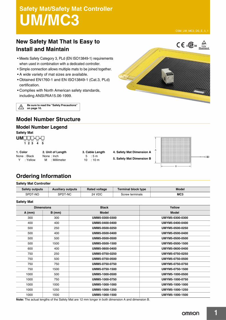
UM/MC3New Safety Mat That Is Easy to Install and Maintain
• Meets Safety Category 3, PLd (EN ISO13849-1) requirements when used in combination with a dedicated controller.
• Simple connection allows multiple mats to be joined together.• A wide variety of mat sizes are available.• Obtained EN1760-1 and EN ISO13849-1 (Cat.3, PLd)
certification.• Complies with North American safety standards,
including ANSI/RIA15.06-1999.
Model Number StructureModel Number LegendSafety Mat
Ordering InformationSafety Mat Controller
Safety Mat
Note: The actual lengths of the Safety Mat are 12 mm longer in both dimension A and dimension B.
Be sure to read the "Safety Precautions" on page 10.
Safety outputs Auxiliary outputs Rated voltage Terminal block type Model
SPDT-NO SPDT-NC 24 VDC Screw terminals MC3
Dimensions Black Yellow
A (mm) B (mm) Model Model
300 300 UMM5-0300-0300 UMYM5-0300-0300
400 400 UMM5-0400-0400 UMYM5-0400-0400
500 250 UMM5-0500-0250 UMYM5-0500-0250
500 400 UMM5-0500-0400 UMYM5-0500-0400
500 500 UMM5-0500-0500 UMYM5-0500-0500
500 1500 UMM5-0500-1500 UMYM5-0500-1500
600 400 UMM5-0600-0400 UMYM5-0600-0400
750 250 UMM5-0750-0250 UMYM5-0750-0250
750 500 UMM5-0750-0500 UMYM5-0750-0500
750 750 UMM5-0750-0750 UMYM5-0750-0750
750 1500 UMM5-0750-1500 UMYM5-0750-1500
1000 500 UMM5-1000-0500 UMYM5-1000-0500
1000 750 UMM5-1000-0750 UMYM5-1000-0750
1000 1000 UMM5-1000-1000 UMYM5-1000-1000
1000 1250 UMM5-1000-1250 UMYM5-1000-1250
1000 1500 UMM5-1000-1500 UMYM5-1000-1500
A
B
UM@@@-@- @– – – – –1 2 3 4 5
1. ColorNone : Black
Y : Yellow
2. Unit of LengthNone : Inch
M : Millimeter
4. Safety Mat Dimension A
5. Safety Mat Dimension B
3. Cable Length5 : 5 m
10 : 10 m
UM/MC3
2
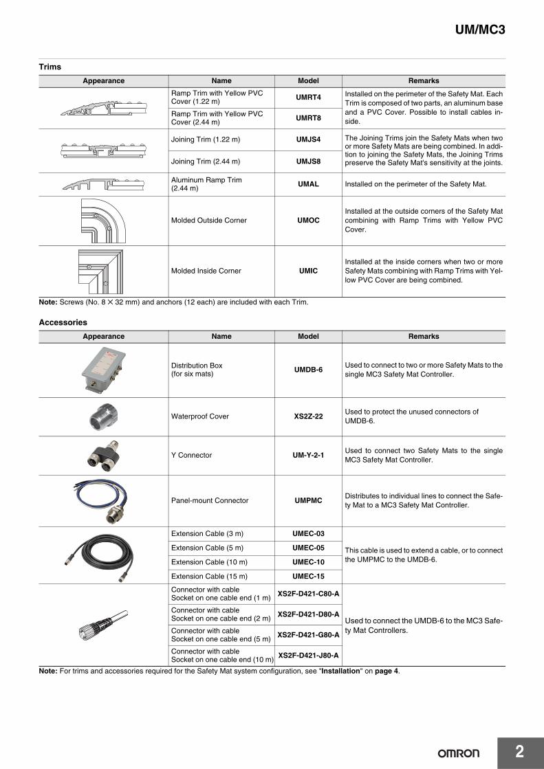
Trims
Note: Screws (No. 8 ✕ 32 mm) and anchors (12 each) are included with each Trim.
Accessories
Note: For trims and accessories required for the Safety Mat system configuration, see "Installation" on page 4.
Appearance Name Model Remarks
Ramp Trim with Yellow PVC Cover (1.22 m) UMRT4 Installed on the perimeter of the Safety Mat. Each
Trim is composed of two parts, an aluminum baseand a PVC Cover. Possible to install cables in-side.
Ramp Trim with Yellow PVC Cover (2.44 m) UMRT8
Joining Trim (1.22 m) UMJS4 The Joining Trims join the Safety Mats when twoor more Safety Mats are being combined. In addi-tion to joining the Safety Mats, the Joining Trimspreserve the Safety Mat's sensitivity at the joints.Joining Trim (2.44 m) UMJS8
Aluminum Ramp Trim(2.44 m) UMAL Installed on the perimeter of the Safety Mat.
Molded Outside Corner UMOCInstalled at the outside corners of the Safety Matcombining with Ramp Trims with Yellow PVCCover.
Molded Inside Corner UMICInstalled at the inside corners when two or moreSafety Mats combining with Ramp Trims with Yel-low PVC Cover are being combined.
Appearance Name Model Remarks
Distribution Box(for six mats) UMDB-6
Used to connect to two or more Safety Mats to thesingle MC3 Safety Mat Controller.
Waterproof Cover XS2Z-22Used to protect the unused connectors ofUMDB-6.
Y Connector UM-Y-2-1Used to connect two Safety Mats to the singleMC3 Safety Mat Controller.
Panel-mount Connector UMPMCDistributes to individual lines to connect the Safe-ty Mat to a MC3 Safety Mat Controller.
Extension Cable (3 m) UMEC-03
This cable is used to extend a cable, or to connectthe UMPMC to the UMDB-6.
Extension Cable (5 m) UMEC-05
Extension Cable (10 m) UMEC-10
Extension Cable (15 m) UMEC-15
Connector with cable Socket on one cable end (1 m) XS2F-D421-C80-A
Used to connect the UMDB-6 to the MC3 Safe-ty Mat Controllers.
Connector with cable Socket on one cable end (2 m) XS2F-D421-D80-A
Connector with cable Socket on one cable end (5 m) XS2F-D421-G80-A
Connector with cable Socket on one cable end (10 m) XS2F-D421-J80-A
3
UM/MC3
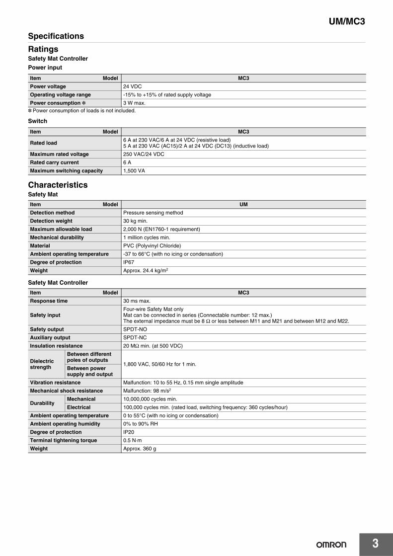
Specifications
RatingsSafety Mat Controller
Power input
* Power consumption of loads is not included.
Switch
CharacteristicsSafety Mat
Safety Mat Controller
Item Model MC3
Power voltage 24 VDC
Operating voltage range -15% to +15% of rated supply voltage
Power consumption * 3 W max.
Item Model MC3
Rated load 6 A at 230 VAC/6 A at 24 VDC (resistive load)5 A at 230 VAC (AC15)/2 A at 24 VDC (DC13) (inductive load)
Maximum rated voltage 250 VAC/24 VDC
Rated carry current 6 A
Maximum switching capacity 1,500 VA
Item Model UM
Detection method Pressure sensing method
Detection weight 30 kg min.
Maximum allowable load 2,000 N (EN1760-1 requirement)
Mechanical durability 1 million cycles min.
Material PVC (Polyvinyl Chloride)
Ambient operating temperature -37 to 66°C (with no icing or condensation)
Degree of protection IP67
Weight Approx. 24.4 kg/m2
Item Model MC3
Response time 30 ms max.
Safety inputFour-wire Safety Mat onlyMat can be connected in series (Connectable number: 12 max.)The external impedance must be 8 Ω or less between M11 and M21 and between M12 and M22.
Safety output SPDT-NO
Auxiliary output SPDT-NC
Insulation resistance 20 MΩ min. (at 500 VDC)
Dielectric strength
Between different poles of outputs
1,800 VAC, 50/60 Hz for 1 min.Between power supply and output
Vibration resistance Malfunction: 10 to 55 Hz, 0.15 mm single amplitude
Mechanical shock resistance Malfunction: 98 m/s2
DurabilityMechanical 10,000,000 cycles min.
Electrical 100,000 cycles min. (rated load, switching frequency: 360 cycles/hour)
Ambient operating temperature 0 to 55°C (with no icing or condensation)
Ambient operating humidity 0% to 90% RH
Degree of protection IP20
Terminal tightening torque 0.5 N·m
Weight Approx. 360 g
UM/MC3
4
InstallationUsing Trim PiecesRamp Trim with Yellow PVC Cover: UMRT4/UMRT8Secures the edges of the Safety Mats to the floor. It is composed of two parts with an aluminum base and a PVC Cover.
Joining Trim: UMJS4/UMJS8The Joining Trims join the Safety Mats when two or more Safety Mats are being combined.In addition to joining the Safety Mats, the Joining Trims preserve the Safety Mat's sensitivity at the joints.
Aluminum Ramp Trim: UMALSecures the edges of the Safety Mat to the floor.The Aluminum Ramp Trim is hollow, so cable can be routed through it.
Molded Outside Corner: UMOCUsed together with the Ramp Trim with Yellow PVC Cover (UMRT4/UMRT8) to secure the external corners of the Safety Mats to the floor.
Molded Inside Corner: UMICUsed together with the Ramp Trim with Yellow PVC Cover (UMRT4/UMRT8) to secure the internal corners of the Safety Mats to the floor.
Note: 1. The Aluminum Ramp Trim or Ramp Trim with Yellow PVC Cover must be cut to fit the size of the Safety Mats being used.Furthermore, when the Safety Mat's wiring is being routed through the Aluminum Ramp Trim or Ramp Trim with Yellow PVC Cover, it will be necessary to cut or notch the Aluminum Ramp Trim or Ramp Trim with Yellow PVC Cover for cable access.Refer to the Safety Mat Instruction Sheet for details on cutting or notching the Aluminum Ramp Trim or Ramp Trim with Yellow PVC Cover.
2. The Joining Trim must be cut to fit the size of the Safety Mats being used.
3. The Ramp Trim with Yellow PVC Cover and Molded Corner must be anchored to the floor to secure the Safety Mats. It is also necessary to drill holes in the Trim to anchor it.Refer to the Safety Mat Instruction Sheet for details on drilling holes in the Trim and Molded Corner and anchoring it to the floor.
Safety Mat ConfigurationThe Safety Mats are secured by anchoring the Ramp Trim with Yellow PVC Cover and Molded Corner to the floor.Before ordering, confirm the number of Ramp Trim with Yellow PVC Cover and Molded Corner pieces that will be needed.
Example 1: Using a Single Safety Mat
In this case, the perimeter of the Safety Mat is about 4 m and the following pieces are required:The example above consists of the following components:
UMYM5-1000-1000 Safety Mat : 1 pieceUMRT4 Ramp Trim with Yellow PVC Cover (1.22 m) : 4 piecesUMOC Molded Outside Corner : 4 pieces
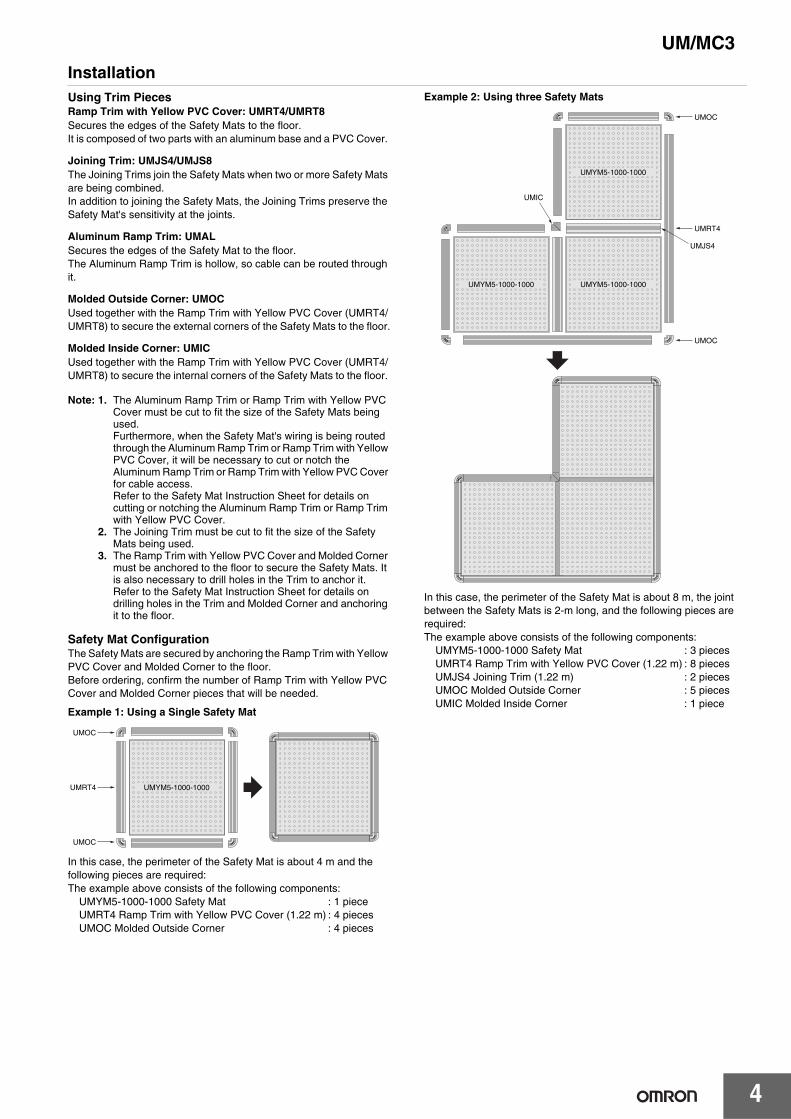
Example 2: Using three Safety Mats
In this case, the perimeter of the Safety Mat is about 8 m, the joint between the Safety Mats is 2-m long, and the following pieces are required:The example above consists of the following components:
UMYM5-1000-1000 Safety Mat : 3 piecesUMRT4 Ramp Trim with Yellow PVC Cover (1.22 m) : 8 piecesUMJS4 Joining Trim (1.22 m) : 2 piecesUMOC Molded Outside Corner : 5 piecesUMIC Molded Inside Corner : 1 piece
UMYM5-1000-1000
UMOC
UMRT4
UMOC
UMRT4
UMOC
UMOC
UMIC
UMJS4
UMYM5-1000-1000
UMYM5-1000-1000UMYM5-1000-1000
5
UM/MC3
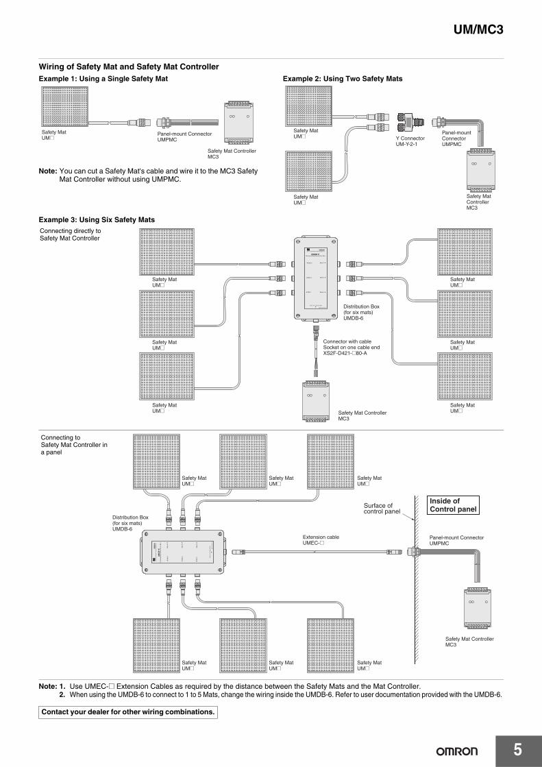
Wiring of Safety Mat and Safety Mat ControllerExample 1: Using a Single Safety Mat
Note: You can cut a Safety Mat's cable and wire it to the MC3 Safety Mat Controller without using UMPMC.
Example 2: Using Two Safety Mats
Example 3: Using Six Safety Mats
Note: 1. Use UMEC-@ Extension Cables as required by the distance between the Safety Mats and the Mat Controller.2. When using the UMDB-6 to connect to 1 to 5 Mats, change the wiring inside the UMDB-6. Refer to user documentation provided with the UMDB-6.
Safety Mat ControllerMC3
Panel-mount ConnectorUMPMC
Safety MatUM@
Safety Mat ControllerMC3
Y ConnectorUM-Y-2-1
Safety MatUM@
Safety MatUM@
Panel-mount ConnectorUMPMC
Contact your dealer for other wiring combinations.
Safety Mat ControllerMC3
Safety MatUM@
Safety MatUM@
Safety MatUM@
Safety MatUM@
Safety MatUM@
Safety MatUM@
Connector with cableSocket on one cable endXS2F-D421-@80-A
Distribution Box(for six mats)UMDB-6
Connecting directly to Safety Mat Controller
Safety Mat ControllerMC3
Safety MatUM@
Safety MatUM@
Safety MatUM@
Safety MatUM@
Safety MatUM@
Safety MatUM@
Panel-mount ConnectorUMPMC
Distribution Box(for six mats)UMDB-6
Extension cableUMEC-@
Surface of control panel
Inside of Control panel
Connecting to Safety Mat Controller in a panel
UM/MC3
6
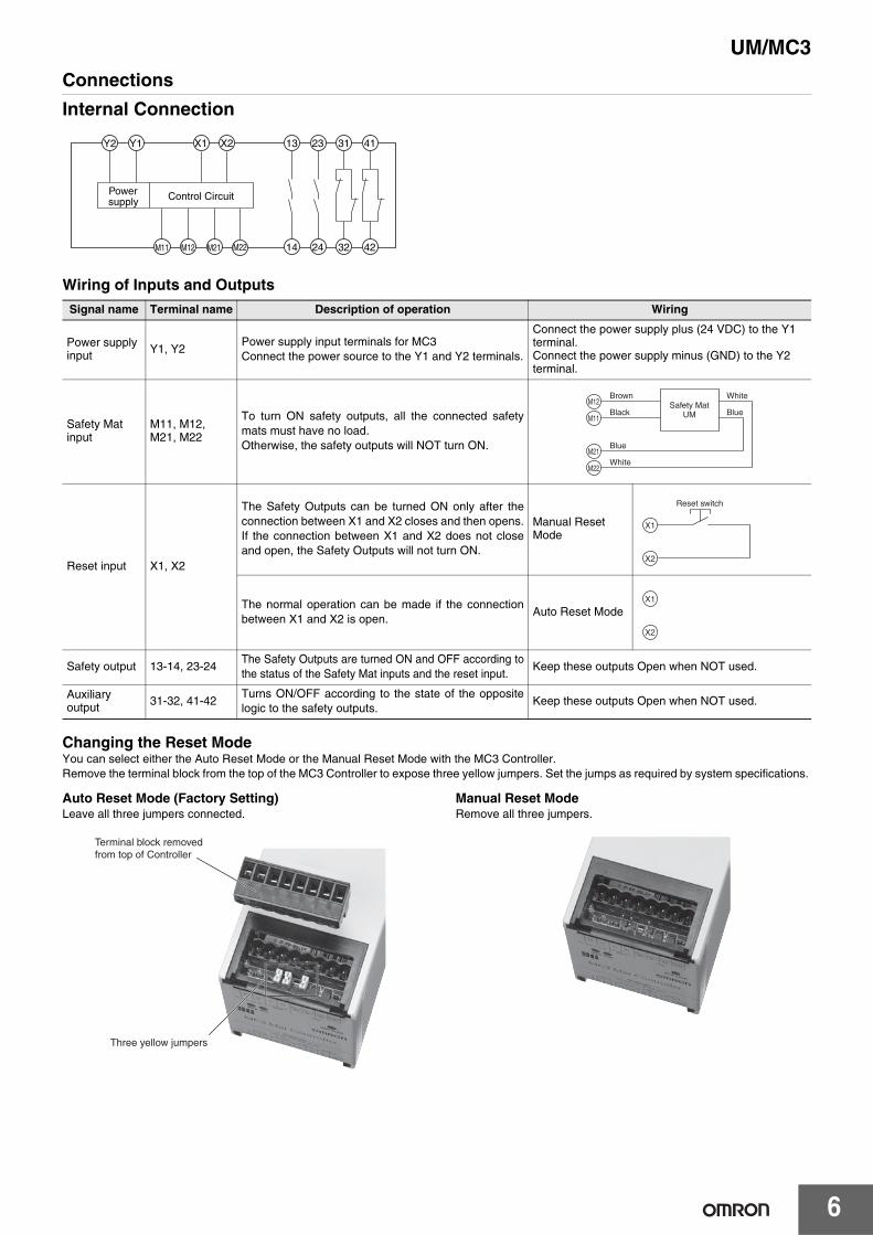
Connections
Internal Connection
Wiring of Inputs and Outputs
Changing the Reset ModeYou can select either the Auto Reset Mode or the Manual Reset Mode with the MC3 Controller. Remove the terminal block from the top of the MC3 Controller to expose three yellow jumpers. Set the jumps as required by system specifications.
Auto Reset Mode (Factory Setting)Leave all three jumpers connected.
Manual Reset ModeRemove all three jumpers.
Signal name Terminal name Description of operation Wiring
Power supply input Y1, Y2
Power supply input terminals for MC3Connect the power source to the Y1 and Y2 terminals.
Connect the power supply plus (24 VDC) to the Y1 terminal.Connect the power supply minus (GND) to the Y2 terminal.
Safety Mat input
M11, M12,M21, M22
To turn ON safety outputs, all the connected safetymats must have no load.Otherwise, the safety outputs will NOT turn ON.
Reset input X1, X2
The Safety Outputs can be turned ON only after theconnection between X1 and X2 closes and then opens.If the connection between X1 and X2 does not closeand open, the Safety Outputs will not turn ON.
Manual Reset Mode
The normal operation can be made if the connectionbetween X1 and X2 is open.
Auto Reset Mode
Safety output 13-14, 23-24The Safety Outputs are turned ON and OFF according tothe status of the Safety Mat inputs and the reset input.
Keep these outputs Open when NOT used.
Auxiliary output 31-32, 41-42
Turns ON/OFF according to the state of the oppositelogic to the safety outputs.
Keep these outputs Open when NOT used.
Control CircuitPowersupply
M21 42322414
2313X2X1Y1Y2 31 41
M12M11 M22
M12Brown
Safety MatUMBlack
White
Blue
Blue
White
M11
M21
M22
Reset switch
X1
X2
X1
X2
Three yellow jumpers
Terminal block removed from top of Controller
7
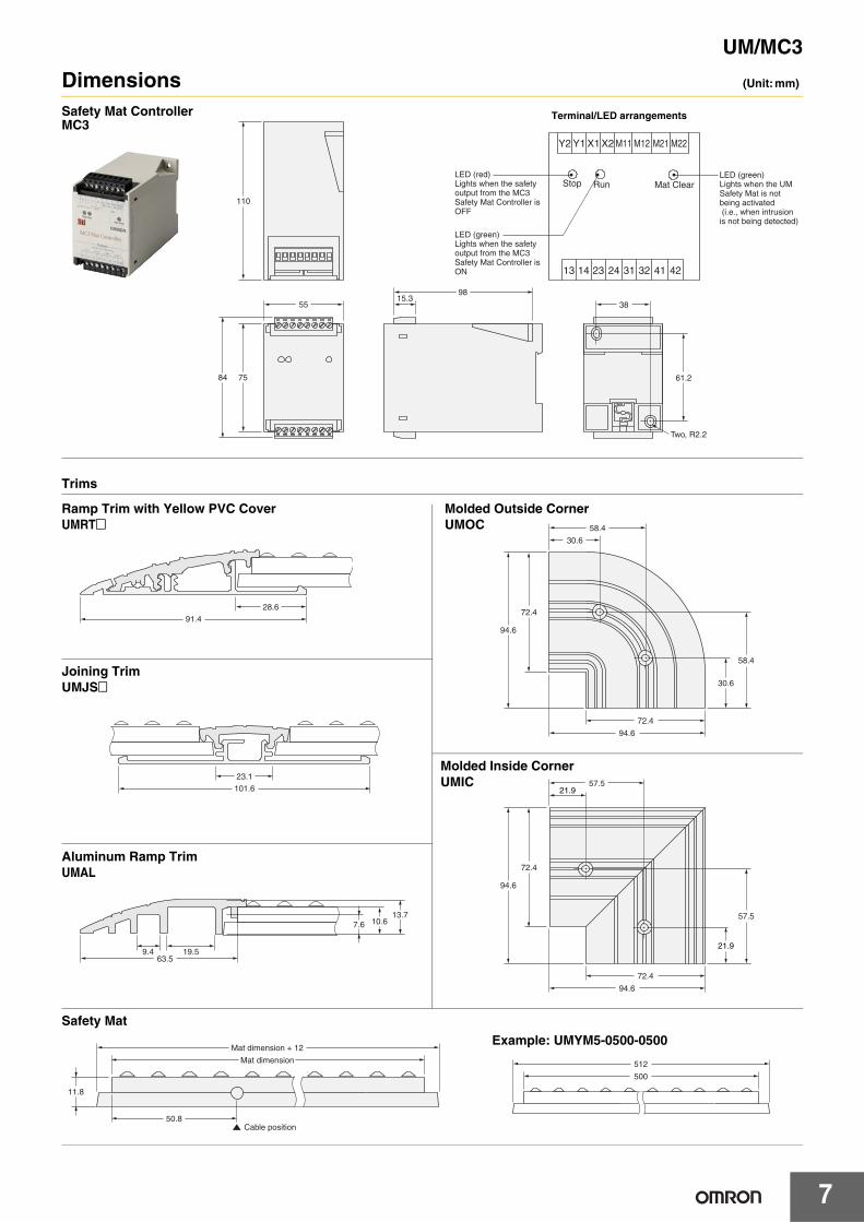
UM/MC3
Dimensions (Unit: mm)
Trims
Safety Mat
Two, R2.2
110
84 75
55 15.3
98
38
61.2
Y2
13 14 23 24 31 32 41 42
Y1 X1 X2 M11 M12 M21 M22
Stop Run Mat Clear LED (red)Lights when the safety output from the MC3 Safety Mat Controller is OFF
LED (green)Lights when the safety output from the MC3 Safety Mat Controller is ON
LED (green)Lights when the UM Safety Mat is not being activated (i.e., when intrusion is not being detected)
Safety Mat ControllerMC3
Terminal/LED arrangements
9.4 19.563.5
7.6 10.613.7
Aluminum Ramp TrimUMAL
23.1
101.6
Ramp Trim with Yellow PVC CoverUMRT@
30.6
30.6
58.4
94.6
72.4
72.4
94.6
58.4
Joining TrimUMJS@
21.9
21.9
57.5
94.6
72.4
72.4
94.6
57.5
Molded Outside CornerUMOC
Molded Inside CornerUMIC
28.6
91.4
512
500
11.8
50.8
Mat dimension
Mat dimension + 12
Cable position
Example: UMYM5-0500-0500
UM/MC3
8
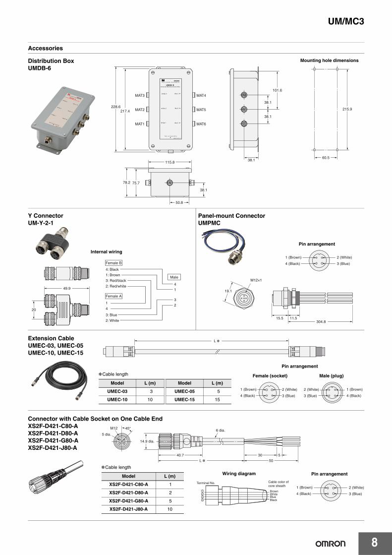
Accessories
MAT4
MAT5
MAT6
115.8
38.1
101.6
38.1
38.1
217.4 228.6
215.9
60.5
78.2 75.7
50.8
38.1
MAT3
MAT2
MAT1
Distribution BoxUMDB-6
Mounting hole dimensions
49.9
20
Female B
Female A
4: Black
1: Brown
3: Red/black
2: Red/white
1
4
3: Blue
2: White
4
Male
1
3
2
1 (Brown)
4 (Black)
2 (White)
3 (Blue)
Y ConnectorUM-Y-2-1
Internal wiring
Panel-mount ConnectorUMPMC
19.1
15.5 11.5304.8
M12×1
Pin arrangement
L *
1 (Brown)
4 (Black)
2 (White)
3 (Blue)
1 (Brown)
4 (Black)
2 (White)
3 (Blue)
Extension CableUMEC-03, UMEC-05UMEC-10, UMEC-15
*Cable length
Model L (m) Model L (m)
UMEC-03 3 UMEC-05 5
UMEC-10 10 UMEC-15 15
Pin arrangement
Female (socket) Male (plug)
6 dia.
40.7
14.9 dia.
L * 50
30 5
45°
5 dia.
M12
Terminal No. Cable color of core sheath
BrownWhiteBlueBlack
1 (Brown)
4 (Black)
2 (White)
3 (Blue)
Connector with Cable Socket on One Cable EndXS2F-D421-C80-AXS2F-D421-D80-AXS2F-D421-G80-AXS2F-D421-J80-A
*Cable length
Model L (m)
XS2F-D421-C80-A 1
XS2F-D421-D80-A 2
XS2F-D421-G80-A 5
XS2F-D421-J80-A 10
Pin arrangementWiring diagram
9
UM/MC3
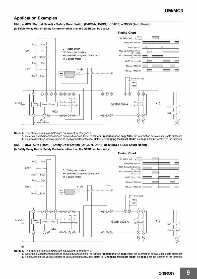
Application ExamplesUM@ + MC3 (Manual Reset) + Safety Door Switch (D4GS-N, D4NS, or D4BS) + G9SB (Auto Reset)(A Safety Relay Unit or Safety Controller other than the G9SB can be used.)
Note: 1. The above circuit examples are equivalent to category 3.2. Determine Mat dimensions based on safe distances. Refer to "Safety Precautions" on page 10 for the information on calculating safe distances.3. Remove the three yellow jumpers to use Manual Reset Mode. Refer to "Changing the Reset Mode" on page 6 for the location of the jumpers.
UM@ + MC3 (Auto Reset) + Safety Door Switch (D4GS-N, D4NS, or D4BS) + G9SB (Auto Reset)(A Safety Relay Unit or Safety Controller other than the G9SB can be used.)
Note: 1. The above circuit examples are equivalent to category 3.2. Determine Mat dimensions based on safe distances. Refer to "Safety Precautions" on page 10 for the information on calculating safe distances.3. Remove the three yellow jumpers to use Manual Reset Mode. Refer to "Changing the Reset Mode" on page 6 for the location of the jumpers.
24 VDC
OPEN
S2
G9SB-2002-A
MC3
KM1
KM2
M
K2
K1Powersupply Control Circuit
KM1
KM2
KM1 KM2
A1
A2
T11 T12 T31 T32 13 23
14 24T21 T22
13 23
14 24Y2
Y1
X1 X2 32 42
31 41M11 M12 M22 M21
Reset switchS1
Blue White
Black Brown
Blue White
Black Brown
UM@
UM@
Feedback Loop
S1: Reset switchS2: Safety door switchKM and KM2: Magnetic ContactorsM: 3-phase motor
Timing Chart
13-14, 23-24
KM1 and KM2 (NC)
KM1 and KM2 (NO)
Reset switch S1
Safety door switch S2
LoadNo loadUM Safety Mat
MC3 Safety Mat Controller
31-32, 41-42MC3 Safety Mat Controller
G9SB 13-14, 23-24
OPEN
S1
MC3
G9SB-2002-APowersupply Control Circuit
24 VDC
KM1
KM2
M
KM1 KM2
K2
K1
A1
A2
13 23
14 24
13 23
14 24Y2
Y1
X1 X2 32 42
31 41
KM1
KM2
T11 T12 T31 T32
T21 T22
M11 M12 M22 M21
Blue White
Black Brown
Blue White
Black Brown
UM@
UM@
Feedback Loop
S1: Safety door switchKM and KM2: Magnetic ContactorsM: 3-phase motor
Timing Chart
13-14, 23-24
KM1 and KM2 (NC)
KM1 and KM2 (NO)
Safety door switch S1
LoadNo loadUM Safety Mat
MC3 Safety Mat Controller
31-32, 41-42MC3 Safety Mat Controller
G9SB 13-14, 23-24
UM/MC3
10
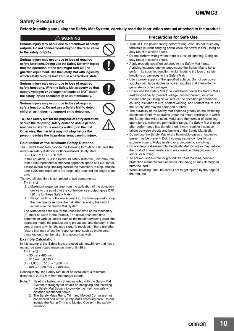
Safety PrecautionsBefore installing and using the Safety Mat System, carefully read the instruction manual attached to the product.
!WARNINGSerious injury may occur due to breakdown of safety outputs. Do not connect loads beyond the rated value to the safety outputs.
Serious injury may occur due to loss of required safety functions. Do not use the Safety Mat with logics that the operation of the mat might turn ON the guarded equipment. Use the Safety Mat with logics by which safety outputs turn OFF in a hazardous state.
Serious injury may occur due to loss of required safety functions. Wire the Safety Mat properly so that supply voltages or voltages for loads do NOT touch the safety inputs accidentally or unintentionally.
Serious injury may occur due to loss of required safety functions. Do not use a Safety Mat to detect children as it does not support child detection.
To use a Safety Mat for the purpose of entry detection, secure the following safety distance until a person reaches a hazardous area by walking on the mat. Otherwise, the machine may not stop before the person reaches the hazardous area, causing injury.
Calculation of the Minimum Safety DistanceThe EN999 standards provide the following formula to calculate theminimum safety distance for floor-installed Safety Mats:
S = (1,600 x T) + 1,200 mmIn this equation, S is the minimum safety distance (unit: mm), the term 1,600 represents a standard approach speed of 1,600 mm/s, T is the overall stop time required for the machinery to stop, and the term 1,200 mm represents the length of a step and the length of an arm.
The overall stop time is comprised of two components:T = t1 + t2t1 : Maximum response time from the activation of the detection
device to the point that the control device's output goes OFF (30 ms for these Safety Mats).
t2 : Response time of the machinery, i.e., the time required to stop the machine or remove the risk after receiving the output signal from the Safety Mat System.
The worst case scenario for the response time of the machinery (t2) must be used in the formula. The actual response time depends on various factors such as the machinery being used, the operating mode, the product being processed, and the point in the control cycle at which the stop signal is received. If there are other factors that may affect the response time, such as brake wear, these factors must be taken into account as well.
Example CalculationIn this example, the Safety Mats are used with machinery that has a measured worst-case response time of 0.485 s.
T = t1 + t2= 30 ms + 485 ms= 515 ms = 0.515 s
S = (1,600 x 0.515) + 1,200 mm= 824 + 1,200 mm = 2,024 mm
Consequently, the Safety Mat must be installed at a minimum distance of 2,024 mm from the danger source.
Note: 1. Read the Instruction Sheet included with the Safety Mat System thoroughly for details on designing and installing the Safety Mat System to provide the minimum safety distance mentioned above.
2. The Safety Mat's Ramp Trim and Molded Corner are not considered part of the Safety Mat's detecting area. Do not include the Ramp Trim and Molded Corner in the safety distance.
• Turn OFF the power supply before wiring. Also, do not touch any terminals (current-carrying parts) while the power is ON. Doing so may result in electric shock.
• Do not perform wiring when there is a risk of lightning. Doing so may result in electric shock.
• Apply properly specified voltages to the Safety Mat inputs. Applying inappropriate voltages cause the Safety Mat to fail to perform its specified function, which leads to the loss of safety functions or damages to the Safety Mat.
• Use a power supply of the specified voltage. Do not use power supplies with large ripples or power supplies that intermittently generate incorrect voltages.
• Do not use the Safety Mat for a load that exceeds the Safety Mat's switching capacity (contact voltage, contact current) or other contact ratings. Doing so will reduce the specified performance, causing insulation failure, contact welding, and contact failure, and the Safety Mat may be damaged or burnt.
• The durability of the Safety Mat depends greatly on the switching conditions. Confirm operation under the actual conditions in which the Safety Mat will be used. Make sure the number of switching operations is within the permissible range. If a Safety Mat is used after performance has deteriorated, it may result in insulation failure between circuits and burning of the Safety Mat itself.
• Do not use the Safety Mat where flammable gases or explosive gases may be present. Doing so may cause combustion or explosion due to Relay heating or arcing during switching.
• Do not drop or disassemble the Safety Mat. Doing so may reduce the product characteristics and may result in damage, electric shock, or burning.
• To prevent short-circuit or ground failure of the load, connect protection elements such as fuses. Not doing so may damage or burn the load.
• When installing trims, be careful not to get injured by the edge of the trim, etc.
Precautions for Safe Use
11
UM/MC3
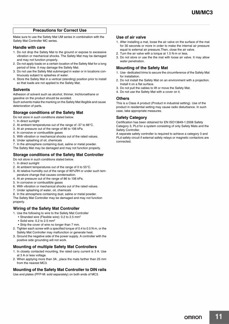
Make sure to use the Safety Mat UM series in combination with the Safety Mat Controller MC series.
Handle with care1. Do not drop the Safety Mat to the ground or expose to excessive
vibration or mechanical shocks. The Safety Mat may be damagedand may not function properly.
2. Do not apply loads on a certain location of the Safety Mat for a longperiod of time. It may damage the Safety Mat.
3. Do not use the Safety Mat submerged in water or in locations con-tinuously subject to splashes of water.
4. Store the Safety Mat in a vertical (standing) position prior to installso that loads are not applied to the Safety Mat.
SolventsAdhesion of solvent such as alcohol, thinner, trichloroethane or gasoline on the product should be avoided.Such solvents make the marking on the Safety Mat illegible and cause deterioration of parts.
Storage conditions of the Safety MatDo not store in such conditions stated below.1. In direct sunlight2. At ambient temperatures out of the range of -37 to 66°C.3. At air pressure out of the range of 86 to 106 kPa.4. In corrosive or combustible gases5. With vibration or mechanical shocks out of the rated values.6. Under splashing of oil, chemicals7. In the atmosphere containing dust, saline or metal powder.The Safety Mat may be damaged and may not function properly.
Storage conditions of the Safety Mat ControllerDo not store in such conditions stated below.1. In direct sunlight2. At ambient temperatures out of the range of 0 to 55°C.3. At relative humidity out of the range of 90%RH or under such tem-
perature change that causes condensation.4. At air pressure out of the range of 86 to 106 kPa.5. In corrosive or combustible gases6. With vibration or mechanical shocks out of the rated values.7. Under splashing of water, oil, chemicals8. In the atmosphere containing dust, saline or metal powder.The Safety Mat Controller may be damaged and may not function properly.
Wiring of the Safety Mat Controller1. Use the following to wire to the Safety Mat Controller
• Stranded wire (Flexible wire): 0.2 to 2.5 mm2
• Solid wire: 0.2 to 2.5 mm2
• Strip the cover of wire no longer than 7 mm.2. Tighten each screw with a specified torque of 0.4 to 0.5 N·m, or the
Safety Mat Controller may malfunction or generate heat.3. Ground the negative side of the power supply. A controller with the
positive side grounding will not work.
Mounting of multiple Safety Mat Controllers1. In closely contacted mounting, the rated carry current is 3 A. Use
at 3 A or less voltage.2. When applying more than 3A , place the mats farther than 25 mm
from the nearest MC3.
Mounting of the Safety Mat Controller to DIN railsUse end plates (PFP-M: sold separately) on both ends of MC3.
Use of air valve1. After installing a mat, loose the air valve on the surface of the mat
for 30 seconds or more in order to make the internal air pressureequal to external air pressure.Then, close the air valve.
2. Turn the air valve with a torque at 1.5 N·m or less.3. Do not store or use the the mat with loose air valve. It may allow
water penetration.
Mounting of the Safety Mat1. Use- dedicated trims to secure the circumference of the Safety Mat
for installation.2. Do not install the Safety Mat on an environment with a projection.
Install it on a flat surface.3. Do not pull the cables to lift or move the Safety Mat.4. Do not use the Safety Mat with a cover on it.
OthersThis is a Class A product (Product in industrial setting). Use of the product in residential setting may cause radio disturbance. In such case, take appropriate measures.
Safety CategoryCertification has been obtained for EN ISO13849-1:2008 Safety Category 3, PLd for a system consisting of only Safety Mats and the Safety Controller.A separate safety controller is required to achieve a category 3 and PLd safety circuit if external safety relays or magnetic contactors are connected.
Precautions for Correct Use
Read and Understand This Catalog Please read and understand this catalog before purchasing the products. Please consult your OMRON representative if you have any questions or comments.
Warranty and Limitations of Liability WARRANTY OMRON's exclusive warranty is that the products are free from defects in materials and workmanship for a period of one year (or other period if specified) from date of sale by OMRON. OMRON MAKES NO WARRANTY OR REPRESENTATION, EXPRESS OR IMPLIED, REGARDING NON-INFRINGEMENT, MERCHANTABILITY, OR FITNESS FOR PARTICULAR PURPOSE OF THE PRODUCTS. ANY BUYER OR USER ACKNOWLEDGES THAT THE BUYER OR USER ALONE HAS DETERMINED THAT THE PRODUCTS WILL SUITABLY MEET THE REQUIREMENTS OF THEIR INTENDED USE. OMRON DISCLAIMS ALL OTHER WARRANTIES, EXPRESS OR IMPLIED. LIMITATIONS OF LIABILITY OMRON SHALL NOT BE RESPONSIBLE FOR SPECIAL, INDIRECT, OR CONSEQUENTIAL DAMAGES, LOSS OF PROFITS OR COMMERCIAL LOSS IN ANY WAY CONNECTED WITH THE PRODUCTS, WHETHER SUCH CLAIM IS BASED ON CONTRACT, WARRANTY, NEGLIGENCE, OR STRICT LIABILITY. In no event shall the responsibility of OMRON for any act exceed the individual price of the product on which liability is asserted. IN NO EVENT SHALL OMRON BE RESPONSIBLE FOR WARRANTY, REPAIR, OR OTHER CLAIMS REGARDING THE PRODUCTS UNLESS OMRON'S ANALYSIS CONFIRMS THAT THE PRODUCTS WERE PROPERLY HANDLED, STORED, INSTALLED, AND MAINTAINED AND NOT SUBJECT TO CONTAMINATION, ABUSE, MISUSE, OR INAPPROPRIATE MODIFICATION OR REPAIR.
Application Considerations SUITABILITY FOR USE OMRON shall not be responsible for conformity with any standards, codes, or regulations that apply to the combination of products in the customer's application or use of the products. At the customer's request, OMRON will provide applicable third party certification documents identifying ratings and limitations of use that apply to the products. This information by itself is not sufficient for a complete determination of the suitability of the products in combination with the end product, machine, system, or other application or use. The following are some examples of applications for which particular attention must be given. This is not intended to be an exhaustive list of all possible uses of the products, nor is it intended to imply that the uses listed may be suitable for the products:
• Outdoor use, uses involving potential chemical contamination or electrical interference, or conditions or uses not described in this catalog. • Nuclear energy control systems, combustion systems, railroad systems, aviation systems, medical equipment, amusement machines, vehicles,
safety equipment, and installations subject to separate industry or government regulations. • Systems, machines, and equipment that could present a risk to life or property.
Please know and observe all prohibitions of use applicable to the products. NEVER USE THE PRODUCTS FOR AN APPLICATION INVOLVING SERIOUS RISK TO LIFE OR PROPERTY WITHOUT ENSURING THAT THE SYSTEM AS A WHOLE HAS BEEN DESIGNED TO ADDRESS THE RISKS, AND THAT THE OMRON PRODUCTS ARE PROPERLY RATED AND INSTALLED FOR THE INTENDED USE WITHIN THE OVERALL EQUIPMENT OR SYSTEM. PROGRAMMABLE PRODUCTS OMRON shall not be responsible for the user's programming of a programmable product, or any consequence thereof.
Disclaimers CHANGE IN SPECIFICATIONS Product specifications and accessories may be changed at any time based on improvements and other reasons. It is our practice to change model numbers when published ratings or features are changed, or when significant construction changes are made. However, some specifications of the products may be changed without any notice. When in doubt, special model numbers may be assigned to fix or establish key specifications for your application on your request. Please consult with your OMRON representative at any time to confirm actual specifications of purchased products. DIMENSIONS AND WEIGHTS Dimensions and weights are nominal and are not to be used for manufacturing purposes, even when tolerances are shown. PERFORMANCE DATA Performance data given in this catalog is provided as a guide for the user in determining suitability and does not constitute a warranty. It may represent the result of OMRON’s test conditions, and the users must correlate it to actual application requirements. Actual performance is subject to the OMRON Warranty and Limitations of Liability. ERRORS AND OMISSIONS The information in this document has been carefully checked and is believed to be accurate; however, no responsibility is assumed for clerical, typographical, or proofreading errors, or omissions.
2010.10
In the interest of product improvement, specifications are subject to change without notice.
OMRON Corporation Industrial Automation Company http://www.ia.omron.com/
(c)Copyright OMRON Corporation 2010 All Right Reserved.