Embed Size (px)
Citation preview

Application Technique
Safety Mat Stop Safety FunctionProducts: MatGuard Safety Mat, GuardLogix Controller, POINT Guard I/O Safety Modules, 100S-C Safety Contactors
Safety Rating: Cat. 3, PLd to ISO 13849-1: 2015
Topic Page
Important User Information 2
Summary of Changes 3
General Safety Information 3
Introduction 4
Safety Function Realization: Risk Assessment 4
Stop Safety Function 4
Safety Function Requirements 5
Functional Safety Description 5
Bill of Material 5
Setup and Wiring 6
Configuration 7
Calculation of the Performance Level 16
Verification and Validation Plan 19
Additional Resources 22

Safety Mat Stop Safety Function
Important User Information
Read this document and the documents listed in the additional resources section about installation, configuration, and operation of this equipment before you install, configure, operate, or maintain this product. Users are required to familiarize themselves with installation and wiring instructions in addition to requirements of all applicable codes, laws, and standards.
Activities including installation, adjustments, putting into service, use, assembly, disassembly, and maintenance are required to be carried out by suitably trained personnel in accordance with applicable code of practice.
If this equipment is used in a manner not specified by the manufacturer, the protection provided by the equipment may be impaired.
In no event will Rockwell Automation, Inc. be responsible or liable for indirect or consequential damages resulting from the use or application of this equipment.
The examples and diagrams in this manual are included solely for illustrative purposes. Because of the many variables and requirements associated with any particular installation, Rockwell Automation, Inc. cannot assume responsibility or liability for actual use based on the examples and diagrams.
No patent liability is assumed by Rockwell Automation, Inc. with respect to use of information, circuits, equipment, or software described in this manual.
Reproduction of the contents of this manual, in whole or in part, without written permission of Rockwell Automation, Inc., is prohibited.
Throughout this manual, when necessary, we use notes to make you aware of safety considerations.
Labels may also be on or inside the equipment to provide specific precautions.
WARNING: Identifies information about practices or circumstances that can cause an explosion in a hazardous environment, which may lead to personal injury or death, property damage, or economic loss.
ATTENTION: Identifies information about practices or circumstances that can lead to personal injury or death, property damage, or economic loss. Attentions help you identify a hazard, avoid a hazard, and recognize the consequence.
IMPORTANT Identifies information that is critical for successful application and understanding of the product.
SHOCK HAZARD: Labels may be on or inside the equipment, for example, a drive or motor, to alert people that dangerous voltage may be present.
BURN HAZARD: Labels may be on or inside the equipment, for example, a drive or motor, to alert people that surfaces may reach dangerous temperatures.
ARC FLASH HAZARD: Labels may be on or inside the equipment, for example, a motor control center, to alert people to potential Arc Flash. Arc Flash will cause severe injury or death. Wear proper Personal Protective Equipment (PPE). Follow ALL Regulatory requirements for safe work practices and for Personal Protective Equipment (PPE).
2 Rockwell Automation Publication SAFETY-AT118B-EN-P - May 2017
Safety Mat Stop Safety Function
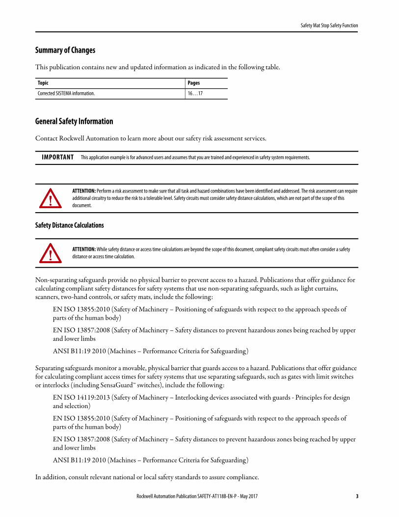
Summary of Changes
This publication contains new and updated information as indicated in the following table.
General Safety Information
Contact Rockwell Automation to learn more about our safety risk assessment services.
Safety Distance Calculations
Non-separating safeguards provide no physical barrier to prevent access to a hazard. Publications that offer guidance for calculating compliant safety distances for safety systems that use non-separating safeguards, such as light curtains, scanners, two-hand controls, or safety mats, include the following:
EN ISO 13855:2010 (Safety of Machinery – Positioning of safeguards with respect to the approach speeds of parts of the human body)
EN ISO 13857:2008 (Safety of Machinery – Safety distances to prevent hazardous zones being reached by upper and lower limbs
ANSI B11:19 2010 (Machines – Performance Criteria for Safeguarding)
Separating safeguards monitor a movable, physical barrier that guards access to a hazard. Publications that offer guidance for calculating compliant access times for safety systems that use separating safeguards, such as gates with limit switches or interlocks (including SensaGuard™ switches), include the following:
EN ISO 14119:2013 (Safety of Machinery – Interlocking devices associated with guards - Principles for design and selection)
EN ISO 13855:2010 (Safety of Machinery – Positioning of safeguards with respect to the approach speeds of parts of the human body)
EN ISO 13857:2008 (Safety of Machinery – Safety distances to prevent hazardous zones being reached by upper and lower limbs
ANSI B11:19 2010 (Machines – Performance Criteria for Safeguarding)
In addition, consult relevant national or local safety standards to assure compliance.
Topic Pages
Corrected SISTEMA information. 16…17
IMPORTANT This application example is for advanced users and assumes that you are trained and experienced in safety system requirements.
ATTENTION: Perform a risk assessment to make sure that all task and hazard combinations have been identified and addressed. The risk assessment can require additional circuitry to reduce the risk to a tolerable level. Safety circuits must consider safety distance calculations, which are not part of the scope of this document.
ATTENTION: While safety distance or access time calculations are beyond the scope of this document, compliant safety circuits must often consider a safety distance or access time calculation.
Rockwell Automation Publication SAFETY-AT118B-EN-P - May 2017 3
Safety Mat Stop Safety Function
Introduction
This safety function application technique explains how to wire, configure, and program a Compact GuardLogix® controller and POINT Guard I/O™ module to monitor a 440F safety mat.
This application technique assumes the use of a dual-channel safety mat. It also assumes that the dual channels are shorted together whenever the safety mat is stepped on. When this type of safety mat is wired directly into a safety input module, there is no way to distinguish between an actual wiring short between the two channels, and someone stepping onto the mat. When either event occurs, a short is created between the channels. For this reason, machine STOP must be the default state when the mat is stepped on. In other words, the machine can never start due to a channel-to-channel field wiring short, which would be possible if stepping onto the mat caused the machine to start.
If a demand is placed on the safety mat or a fault is detected in the monitoring circuit, the GuardLogix controller de-energizes the final control device, in this case, a redundant pair of 100S contactors.
This example uses a Compact GuardLogix controller, but is applicable to any GuardLogix controller. This example uses a 440F Safety Mat, but is applicable to any dual-channel safety mat that shorts the channels together when the mat is stepped on. The SISTEMA calculations that are shown later in this document would have to be recalculated using the actual products.
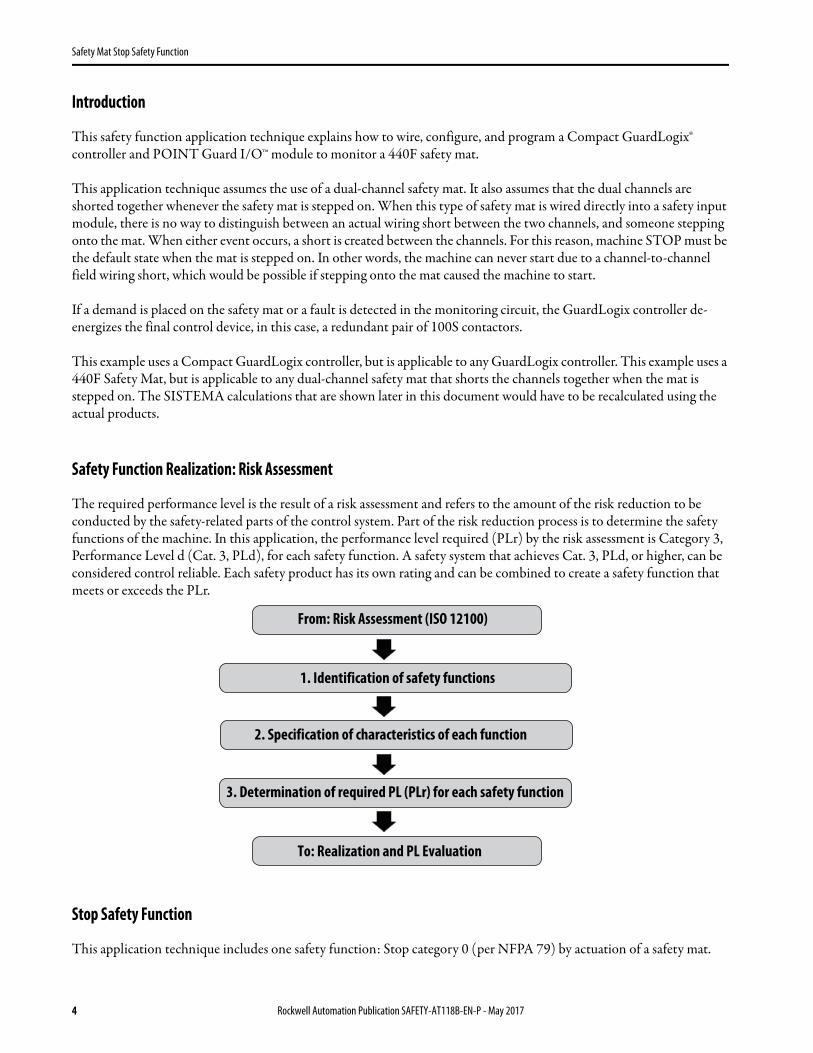
Safety Function Realization: Risk Assessment
The required performance level is the result of a risk assessment and refers to the amount of the risk reduction to be conducted by the safety-related parts of the control system. Part of the risk reduction process is to determine the safety functions of the machine. In this application, the performance level required (PLr) by the risk assessment is Category 3, Performance Level d (Cat. 3, PLd), for each safety function. A safety system that achieves Cat. 3, PLd, or higher, can be considered control reliable. Each safety product has its own rating and can be combined to create a safety function that meets or exceeds the PLr.
Stop Safety Function
This application technique includes one safety function: Stop category 0 (per NFPA 79) by actuation of a safety mat.
From: Risk Assessment (ISO 12100)
1. Identification of safety functions
2. Specification of characteristics of each function
3. Determination of required PL (PLr) for each safety function
To: Realization and PL Evaluation
4 Rockwell Automation Publication SAFETY-AT118B-EN-P - May 2017

Safety Mat Stop Safety Function
Safety Function Requirements
Placing a demand on the safety mat stops and prevents hazardous motion by removal of power to the motor. When the safety mat is reset, hazardous motion and power to the motor do not resume until a secondary action (start button depressed) occurs. Whenever possible, faults at the safety mat, wiring terminals, or safety controller are detected before the next safety demand. As previously mentioned, channel-to-channel shorts are undetectable in this application. The safety distance location of the safety mat must be established so that hazardous motion must be stopped before the operator can reach the hazard. The safety function in this example is capable of connecting and interrupting power to motors rated up to 9 A, 600V AC.
The safety function in this application technique meets or exceeds the requirements for Category 3, Performance Level d (Cat. 3, PLd), per ISO 13849-1 and control reliable operation per ANSI B11.19.
Functional Safety Description
Hazardous motion is interrupted or prevented by stepping onto the safety mat. The safety mat (SM1) is wired to a pair of safety inputs of a safety input module (SI1). The safety contactors (K1 and K2) are connected to a pair of safety outputs of a safety output module (SO1). The I/O module is connected via CIP Safety™ over an EtherNet/IP™ network to the safety controller (SC1). The safety code in SC1 monitors the status of the safety mat (SM1) by using the pre-certified safety instruction 'Safety Mat' (SMAT). When all safety input interlocks are satisfied, no faults are detected, and the reset push button is pressed, a second certified function block called Configurable Redundant Output (CROUT) controls and monitors feedback for a pair of 100S redundant contactors. In summary, when the safety mat is stepped on, the contactors drop out. When the operator steps off the safety mat, and the reset button is pressed (Manual Mode), the contactors are energized. When in Automatic Mode, the contactors can be energized when the operator steps off the mat.
Bill of Material
This application technique uses these products.
Cat. No. Description Quantity
440F-M2020BYNN MatGuard™ safety mat, 1000 mm x 1000 mm (39.37 in. x 39.37 in.), 4.5 m (14.76 ft) cables, yellow 1
800FM-G611MX10 800F Reset push button, metal, guarded, blue, R, metal latch mount, one normally open contact, standard 1
100S-C09ZJ23C Bulletin 100S-C safety contactors 2
1768-ENBT CompactLogix™ EtherNet/IP bridge module 1
1768-L43S Compact GuardLogix processor, 2.0 MB standard memory, 0.5 MB safety memory 1
1768-PA3 Power supply, 120/240V AC input, 3.5 A at 24V DC 1
1769-ECR Right-end cap and terminator 1
1734-AENT 24V DC Ethernet adapter 1
1734-TB Module base with removable IEC screw terminals 4
1734-IB8S POINT Guard I/O safety input module 1
1734-OB8S POINT Guard I/O safety output module 1
1783-US05T Stratix® 2000 unmanaged Ethernet switch 1
Rockwell Automation Publication SAFETY-AT118B-EN-P - May 2017 5
Safety Mat Stop Safety Function
Setup and Wiring
For detailed information on how to install and wire, refer to the publications listed in the Additional Resources.
System Overview
The 1734-IB8S module sources the 24V DC for both channels by using two test outputs. The 1734-IB8S module sinks the channels by using two safety inputs. The SMAT instruction toggles the test outputs (sources) so that they are always diverse. The SMAT instruction verifies that the inputs are always diverse.
When the mat is stepped on, a channel-to-channel short occurs, and the high channel has a path to both inputs. The SMAT instruction detects that the inputs are not diverse, and drops the SMAT output.
Shorts to 0V DC, shorts to 24V DC, and wire breaks cause the toggling channels to operate improperly, thus making the fault detectable. The SMAT instruction sets the fault present (FP) output when any of these faults occur. After the fault is cleared, and the reset is pressed, the SMAT instruction can reset its output.
The final control device in this case is a pair of 100S safety contactors, K1 and K2. The contactors are controlled by a 1734-OBS safety output module. The contactors are wired in a redundant-series configuration. A feedback circuit is wired through the normally open contacts and back to an input on the 1734-IB8S module to monitor the contactors for proper operation. The contactors cannot restart if the feedback circuit is not in the correct state.
The system has individual reset buttons for resetting faults and safety outputs.
The reset buttons and the contactor feedback circuit are all wired to the 1734-IB8S module in this example. This is not required for functional safety. These three inputs could be wired to a standard input module.
6 Rockwell Automation Publication SAFETY-AT118B-EN-P - May 2017

Safety Mat Stop Safety Function
Electrical Schematic
Configuration
The Compact GuardLogix controller is configured by using the RSLogix 5000® application, version 17 or later. You must create a project and add the I/O modules. Then, configure the I/O modules for the correct input and output types. A detailed description of each step is beyond the scope of this document. Knowledge of the RSLogix 5000 programming environment is assumed.
Configure the SMAT Instruction
24V DC
Safety Reset Fault Reset
Safety Mat
24V DC Common
Rockwell Automation Publication SAFETY-AT118B-EN-P - May 2017 7

Safety Mat Stop Safety Function
The Short Circuit Detect Delay Time (SCDDT) defines how long the SMAT instruction waits before declaring that two high (1)channels at the safety inputs was caused by a fault and not by someone stepping on the mat. When the mat is stepped on, the SMAT instruction sees the high equivalency at the inputs and sets the test outputs to low (0). If both channels were high (1) and both channels transition to low (0) before the SCDDT timer expires, the SMAT instruction recognizes that someone is standing on the mat. Any other channel reaction is an indication that some other fault has occurred. So the SCDDT has to be longer than the time it takes for the SMAT instruction to attempt to reset both channels.
The 1734-IB8S Input Error Latch Time (IELT) is highlighted in the image shown. The IELT defines the time any fault of the input module remains active before the module allows it to be reset. If the IELT is longer than the SCDDT, then the test output fault that occurs when the mat is stepped on is still active when the SCDDT expires. This causes the SMAT instruction to declare a fault every time someone steps on the mat. The SCDDT must be greater than the IELT value configured for the 1734-IE4S module. In the images that are shown, the IELT is 50 ms and the SCDDT is 100 ms.
Configure the Controller and Add I/O Modules
Follow these steps to configure the controller and to add the I/O modules.
1. In the RSLogix 5000® software, create a project.
8 Rockwell Automation Publication SAFETY-AT118B-EN-P - May 2017

Safety Mat Stop Safety Function
2. In the Controller Organizer, add the 1768-ENBT module to the 1768 Bus.
3. Select the 1768-ENBT module and click OK.
4. In the New Module dialog box, do the following: a. Name the module.b. Type its IP address.
This example uses 192.168.1.8 as the IP address. Your IP address can differ.c. Click OK.
Rockwell Automation Publication SAFETY-AT118B-EN-P - May 2017 9

Safety Mat Stop Safety Function
5. Add the 1734-AENT adapter by right-clicking the 1768-ENBT module in the Controller Organizer and choosing New Module.
6. Select the 1734-AENT adapter and click OK.
7. In the New Module dialog box, do the following:d. Name the module.e. Type its IP address,
This example uses 192.168.1.11 as the IP address. Your IP address can differ. f. Click OK. g. Click Change.
10 Rockwell Automation Publication SAFETY-AT118B-EN-P - May 2017
Safety Mat Stop Safety Function
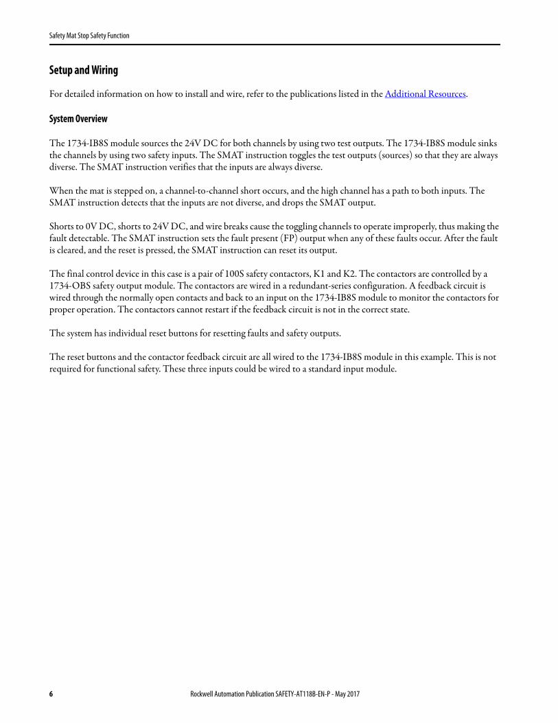
8. Set the Chassis Size as 3 for the 1734-AENT adapter and click OK.
Chassis size is the number of modules that are inserted in the chassis. The 1734-AENT adapter is considered to be in slot 0, so for one input and one output module, the chassis size is 3.
9. In the Controller Organizer, right-click the 1734-AENT adapter and choose New Module.
10. Expand Safety, select the 1734-IB8S module, and click OK.
11. In the New Module dialog box, name the device 'IB8S'and click Change.
Rockwell Automation Publication SAFETY-AT118B-EN-P - May 2017 11
Safety Mat Stop Safety Function
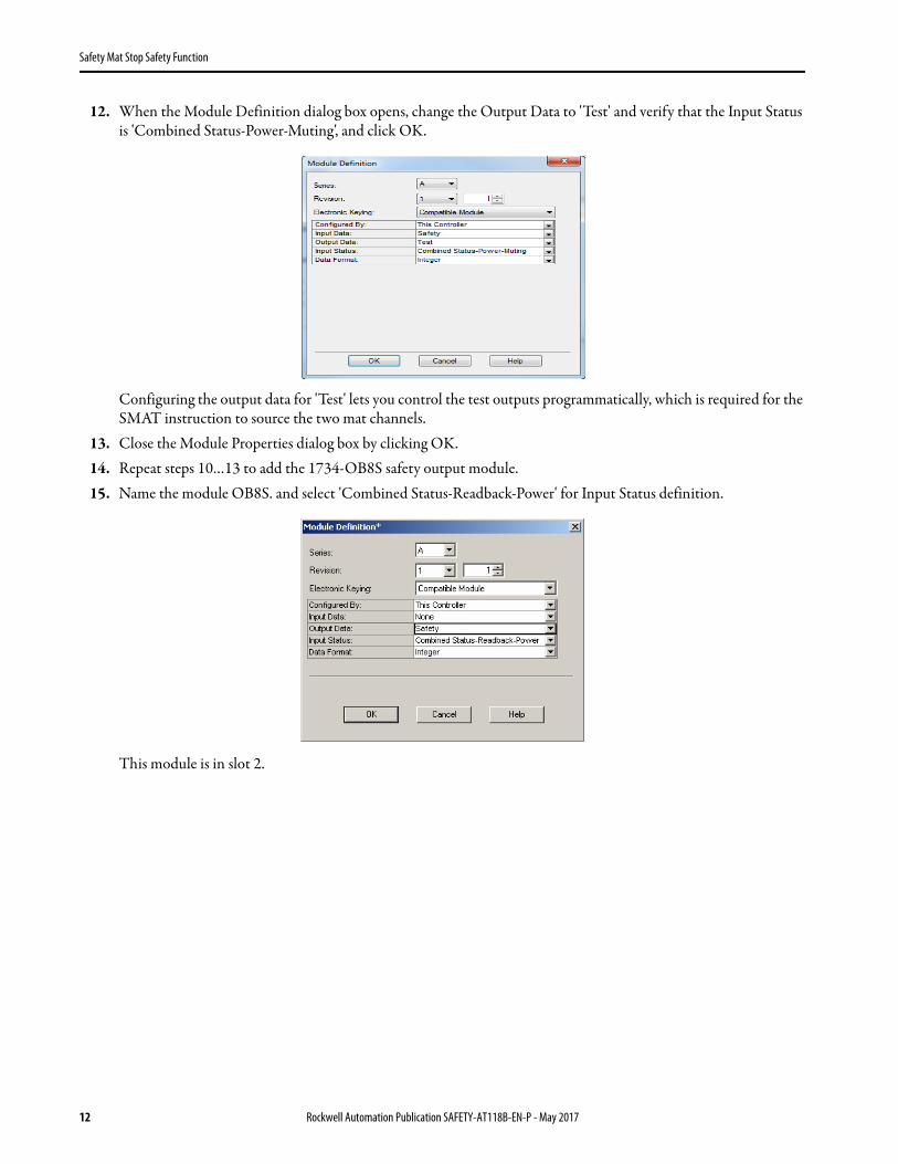
12. When the Module Definition dialog box opens, change the Output Data to 'Test' and verify that the Input Status is 'Combined Status-Power-Muting', and click OK.
Configuring the output data for 'Test' lets you control the test outputs programmatically, which is required for the SMAT instruction to source the two mat channels.
13. Close the Module Properties dialog box by clicking OK.14. Repeat steps 10…13 to add the 1734-OB8S safety output module. 15. Name the module OB8S. and select 'Combined Status-Readback-Power' for Input Status definition.
This module is in slot 2.
12 Rockwell Automation Publication SAFETY-AT118B-EN-P - May 2017
Safety Mat Stop Safety Function
Configure the I/O Modules
Follow these steps to configure the POINT Guard I/O modules.
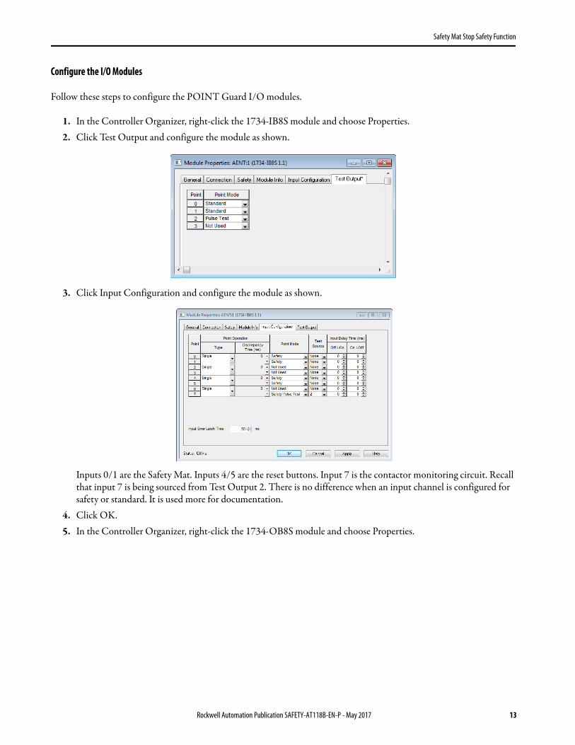
1. In the Controller Organizer, right-click the 1734-IB8S module and choose Properties.2. Click Test Output and configure the module as shown.
3. Click Input Configuration and configure the module as shown.
Inputs 0/1 are the Safety Mat. Inputs 4/5 are the reset buttons. Input 7 is the contactor monitoring circuit. Recall that input 7 is being sourced from Test Output 2. There is no difference when an input channel is configured for safety or standard. It is used more for documentation.
4. Click OK.5. In the Controller Organizer, right-click the 1734-OB8S module and choose Properties.
Rockwell Automation Publication SAFETY-AT118B-EN-P - May 2017 13
Safety Mat Stop Safety Function
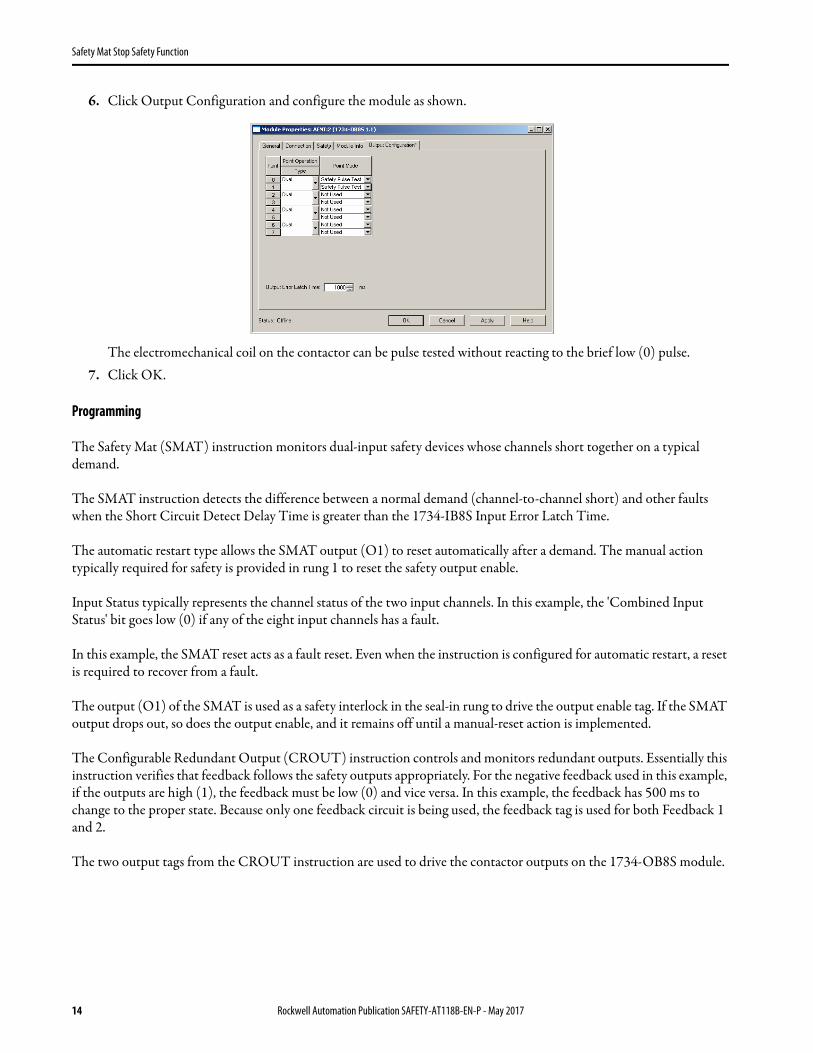
6. Click Output Configuration and configure the module as shown.
The electromechanical coil on the contactor can be pulse tested without reacting to the brief low (0) pulse.7. Click OK.
Programming
The Safety Mat (SMAT) instruction monitors dual-input safety devices whose channels short together on a typical demand.
The SMAT instruction detects the difference between a normal demand (channel-to-channel short) and other faults when the Short Circuit Detect Delay Time is greater than the 1734-IB8S Input Error Latch Time.
The automatic restart type allows the SMAT output (O1) to reset automatically after a demand. The manual action typically required for safety is provided in rung 1 to reset the safety output enable.
Input Status typically represents the channel status of the two input channels. In this example, the 'Combined Input Status' bit goes low (0) if any of the eight input channels has a fault.
In this example, the SMAT reset acts as a fault reset. Even when the instruction is configured for automatic restart, a reset is required to recover from a fault.
The output (O1) of the SMAT is used as a safety interlock in the seal-in rung to drive the output enable tag. If the SMAT output drops out, so does the output enable, and it remains off until a manual-reset action is implemented.
The Configurable Redundant Output (CROUT) instruction controls and monitors redundant outputs. Essentially this instruction verifies that feedback follows the safety outputs appropriately. For the negative feedback used in this example, if the outputs are high (1), the feedback must be low (0) and vice versa. In this example, the feedback has 500 ms to change to the proper state. Because only one feedback circuit is being used, the feedback tag is used for both Feedback 1 and 2.
The two output tags from the CROUT instruction are used to drive the contactor outputs on the 1734-OB8S module.
14 Rockwell Automation Publication SAFETY-AT118B-EN-P - May 2017

Safety Mat Stop Safety Function
Falling Edge Reset
ISO 13849-1 stipulates that instruction reset functions must occur on falling edge signals. To comply with this requirement, a One Shot Falling instruction is used on the rung immediately preceding the Cmd_Zone1_OutputEnable rung. Then, the OSF instruction Output Bit tag is used as the reset bit for the following rung. The Cmd_Zone1_OutputEnable is still used to enable the CROUT instruction.
Rung 1 would be replaced by the two rungs shown in the graphic.
Rockwell Automation Publication SAFETY-AT118B-EN-P - May 2017 15

Safety Mat Stop Safety Function
Calculation of the Performance Level
When properly implemented, this safety mat safety function can achieve a safety rating of Category 3, PerformanceLevel d (Cat. 3, PLd), according to ISO 13849-1: 2015, as calculated by using the Safety Integrity Software Tool for the Evaluation of Machine Applications (SISTEMA).
The individual subsystem values are shown in the graphic.
The overall performance level that is achieved is shown in the graphic.
The safety mat stop safety function can be modeled as follows.
Calculations are based on one operation of the safety mat per hour; therefore 8760 operations of contactors per year.
The measures against common cause failure (CCF) are quantified using the scoring process outlined in Annex F of ISO 13849-1. For the purposes of the PL calculation, the required score of 65 needed to fulfill the CCF requirement is considered to be met. The complete CCF scoring process must be done when implementing this example.
IMPORTANT To calculate the PL of your entire safety function, you must include the specific subsystems that you chose. Depending on the devices you choose, the overall safety rating of your system will be different.
Safety MatChannel A
Safety MatChannel B
Input Logic Output
1734-IB8S 1734-OB8S
100S-C Contactor
K1
100S-C Contactor
K2
1768-L43S
Subsystem 1 Subsystem 2 Subsystem 3 Subsystem 4 Subsystem 5
16 Rockwell Automation Publication SAFETY-AT118B-EN-P - May 2017

Safety Mat Stop Safety Function
Fault exclusion was used for the safety mat subsystem. A PLd was entered manually for this subsystem. Because fault exclusion was used, this subsystem is not included in the overall safety function PFH calculation; thus a value of 0 is used. This configuration derates the overall safety function to PLd.
Because these devices are electromechanical devices, the safety contactor data includes the following:• Mean Time to Failure, dangerous (MTTFd)• Diagnostic Coverage (DCavg)• Common Cause Failure (CCF)
The functional safety evaluations of the electromechanical devices include the following:• How frequently they are operated• Whether they are effectively monitored for faults• Whether they are properly specified and installed
Rockwell Automation Publication SAFETY-AT118B-EN-P - May 2017 17

Safety Mat Stop Safety Function
SISTEMA calculates the MTTFd by using B10d data provided for the contactors along with the estimated frequency of use, entered during the creation of the SISTEMA project. For this safety function, one cycle per hour, 8760 annually, was used in the SISTEMA calculation.
The DCavg (99%) for the contactors is selected from the Output Device table of ISO 13849-1 Annex E, Direct Monitoring.
The CCF value is generated by using the scoring process outlined in Annex F of ISO 13849-1. The complete CCF scoring process must be performed when actually implementing an application. A minimum score of 65 must be achieved.
18 Rockwell Automation Publication SAFETY-AT118B-EN-P - May 2017
Safety Mat Stop Safety Function
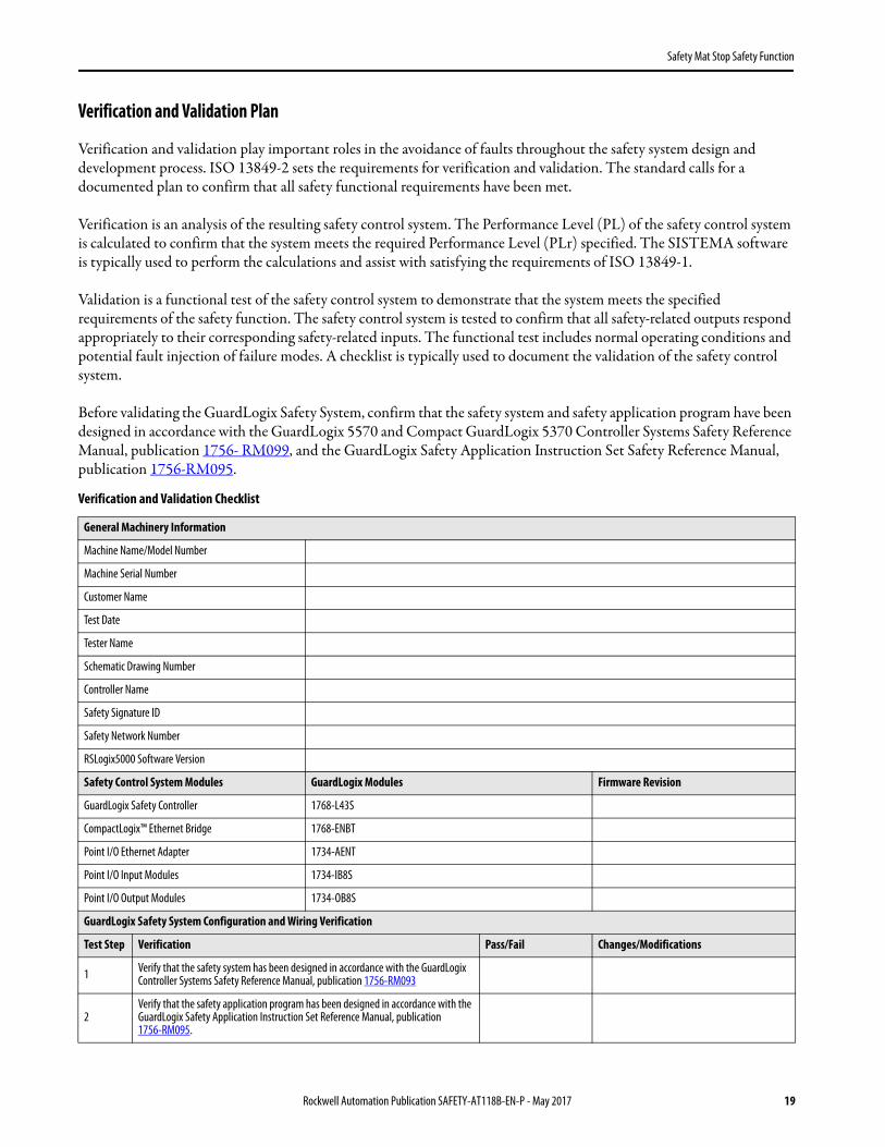
Verification and Validation Plan
Verification and validation play important roles in the avoidance of faults throughout the safety system design and development process. ISO 13849-2 sets the requirements for verification and validation. The standard calls for a documented plan to confirm that all safety functional requirements have been met.
Verification is an analysis of the resulting safety control system. The Performance Level (PL) of the safety control system is calculated to confirm that the system meets the required Performance Level (PLr) specified. The SISTEMA software is typically used to perform the calculations and assist with satisfying the requirements of ISO 13849-1.
Validation is a functional test of the safety control system to demonstrate that the system meets the specified requirements of the safety function. The safety control system is tested to confirm that all safety-related outputs respond appropriately to their corresponding safety-related inputs. The functional test includes normal operating conditions and potential fault injection of failure modes. A checklist is typically used to document the validation of the safety control system.
Before validating the GuardLogix Safety System, confirm that the safety system and safety application program have been designed in accordance with the GuardLogix 5570 and Compact GuardLogix 5370 Controller Systems Safety Reference Manual, publication 1756- RM099, and the GuardLogix Safety Application Instruction Set Safety Reference Manual, publication 1756-RM095.
Verification and Validation Checklist
General Machinery Information
Machine Name/Model Number
Machine Serial Number
Customer Name
Test Date
Tester Name
Schematic Drawing Number
Controller Name
Safety Signature ID
Safety Network Number
RSLogix5000 Software Version
Safety Control System Modules GuardLogix Modules Firmware Revision
GuardLogix Safety Controller 1768-L43S
CompactLogix™ Ethernet Bridge 1768-ENBT
Point I/O Ethernet Adapter 1734-AENT
Point I/O Input Modules 1734-IB8S
Point I/O Output Modules 1734-OB8S
GuardLogix Safety System Configuration and Wiring Verification
Test Step Verification Pass/Fail Changes/Modifications
1 Verify that the safety system has been designed in accordance with the GuardLogix Controller Systems Safety Reference Manual, publication 1756-RM093
2Verify that the safety application program has been designed in accordance with the GuardLogix Safety Application Instruction Set Reference Manual, publication 1756-RM095.
Rockwell Automation Publication SAFETY-AT118B-EN-P - May 2017 19

Safety Mat Stop Safety Function
3 Visually inspect the safety system network and verify that the I/O is wired as documented in the schematics.
4 Visually inspect the application program to verify that the safety system network and I/O module configuration is configured as documented.
5Visually inspect the application program to verify suitable safety certified instructions are used. The logic is readable, understandable, and testable with the aid of clear comments.
6 Verify that all input devices are qualified by cycling their respective actuators. Monitor the status in the Controller Tags window.
7 Verify that all output devices are qualified by cycling their respective actuators. Monitor the status in the Controller Tags window.
Normal Operation Verification - The GuardLogix safety system responds properly to all normal Start, Stop, and Reset commands.
Test Step Verification Pass/Fail Changes/Modifications
1Initiate a Start Command. Both contactors energize for a normal machine run condition. Verify proper machine status indication and safety application program indication.
2Initiate a Stop command. Both contactors de-energize for a normal machine Stop condition. Verify proper machine status indication and safety application program indication.
3While the system continues to run, step onto the safety mat. Both contactors de-energize and open for a normal safe condition. Verify proper machine status indication and safety application program indication. Repeat for all mats.
4
While the system is stopped and the operator is standing on the mat, initiate a Start Command. Both contactors remain de-energized and open for a normal safe condition. Verify proper machine status indication and safety application program indication. Repeat for all mats.
5 Initiate a Reset command. Both contactors remain de-energized. Verify proper machine status indication and safety application program indication.
Validation of Safe Response to Abnormal Operation - The safety system responds properly to all foreseeable faults with corresponding diagnostics.
Safety Mat Input Tests
Test Step Validation Pass/Fail Changes/Modifications
1
While the system continues to run, remove the channel 1 wire from the safety I/O. Both contactors de-energize. Verify proper machine status indication and safety application program indication. Verify that the system is unable to reset and restart with a fault. Restore channel 1 and repeat for channel 2.
2
While the system continues to run, short channel 1 of the safety I/O to 24V DC. Both contactors de-energize. Verify proper machine status indication and safety application program indication. Verify that the system is unable to reset and restart with a fault. Restore channel 1 and repeat for channel 2
3
While the system continues to run, short channel 1 of the safety I/O to 0V DC. Both contactors de-energize. Verify proper machine status indication and safety application program indication. Verify that the system is unable to reset and restart with a fault. Restore channel 1 and repeat for channel 2.
4
While the system continues to run, short channels 1 and 2 of the safety I/O. Both contactors de-energize. Verify proper machine status indication and safety application program indication. As this condition cannot be differentiated from normal demand, verify that the system is able to reset and restart. Restore channel 1 and 2 wiring.
Verification and Validation Checklist (continued)
20 Rockwell Automation Publication SAFETY-AT118B-EN-P - May 2017

Safety Mat Stop Safety Function
Validation of Safe Response to Abnormal Operation - The safety system responds properly to all foreseeable faults with corresponding diagnostics.
GuardLogix Controller and Network Tests
Test Step Validation Pass/Fail Changes/Modifications
1
While the system continues to run, remove the Ethernet network connection between the safety I/O and the controller. All contactors de-energize. Verify proper machine status indication and I/O connection status in the safety application program.
2Restore the safety I/O module network connection and allow time to re-establish communication. Verify the Connection Status Bit in the safety application program. Repeat for all safety I/O connections.
3
While the system continues to run, switch the controller out of Run mode. All contactors de-energize. Return the key switch to Run mode. All contactors remain de-energized. Verify proper machine status indication and safety application program indication.
Validation of Safe Response to Abnormal Operation - The safety system responds properly to all foreseeable faults with corresponding diagnostics.
Safety Contactor Output Tests
Test Step Validation Pass/Fail Changes/Modifications
1Initiate a Start command. Both contactors energize for a normal machine run condition. Verify proper machine status indication and safety application program indication.
2
While the system continues to run, remove the contactor feedback from the safetyI/O. All contactors remain energized. Initiate a Stop command and attempt a Reset command. The system does not restart or reset. Verify proper machine status indication and safety application program indication.
3
While the system continues to run, short the contactor feedback to the safety I/O. All contactors remain energized. Initiate a Stop command and attempt a Reset command. The system does not restart or reset. Verify proper machine status indication and safety application program indication.
Verification and Validation Checklist (continued)
Rockwell Automation Publication SAFETY-AT118B-EN-P - May 2017 21
Safety Mat Stop Safety Function
Additional Resources
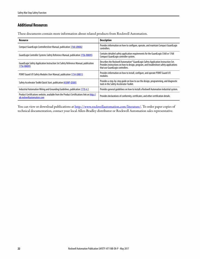
These documents contain more information about related products from Rockwell Automation.
You can view or download publications at http://www.rockwellautomation.com/literature/. To order paper copies of technical documentation, contact your local Allen-Bradley distributor or Rockwell Automation sales representative.
Resource Description
Compact GuardLogix ControllersUser Manual, publication 1768-UM002 Provides information on how to configure, operate, and maintain Compact GuardLogix controllers.
GuardLogix Controller Systems Safety Reference Manual, publication 1756-RM093 Contains detailed safety application requirements for the GuardLogix 5560 or 1768 Compact GuardLogix controller system.
GuardLogix Safety Application Instruction Set Safety Reference Manual, publication 1756-RM095
Describes the Rockwell Automation® GuardLogix Safety Application Instruction Set. Provides instructions on how to design, program, and troubleshoot safety applications that use GuardLogix controllers.
POINT Guard I/O Safety Modules User Manual, publication 1734-UM013 Provides information on how to install, configure, and operate POINT Guard I/O modules.
Safety Accelerator Toolkit Quick Start, publication IASIMP-QS005 Provides a step-by-step guide on how to use the design, programming, and diagnostic tools in the Safety Accelerator Toolkit.
Industrial Automation Wiring and Grounding Guidelines, publication 1770-4.1 Provides general guidelines on how to install a Rockwell Automation industrial system.
Product Certifications website, available from the Product Certifications link on http://ab.rockwellautomation.com Provides declarations of conformity, certificates, and other certification details.
22 Rockwell Automation Publication SAFETY-AT118B-EN-P - May 2017

Safety Mat Stop Safety Function
Notes:
Rockwell Automation Publication SAFETY-AT118B-EN-P - May 2017 23

Allen-Bradley, CompactLogix, GuardLogix, LISTEN. THINK. SOLVE., MatGuard, POINT Guard I/O, Rockwell Automation, Rockwell Software, RSLogix 5000, SensaGuard, and Stratix are trademarks of Rockwell Automation, Inc.CIP Safety and EtherNet/IP are trademarks of ODVA, Inc.Trademarks not belonging to Rockwell Automation are property of their respective companies.
Publication SAFETY-AT118B-EN-P - May 2017
Rockwell Automation SupportUse the following resources to access support information.
Documentation FeedbackYour comments will help us serve your documentation needs better. If you have any suggestions on how to improve this document, complete the How Are We Doing? form at http://literature.rockwellautomation.com/idc/groups/literature/documents/du/ra-du002_-en-e.pdf.
Technical Support Center Knowledgebase Articles, How-to Videos, FAQs, Chat, User Forums, and Product Notification Updates. www.rockwellautomation.com/knowledgebase
Local Technical Support Phone Numbers Locate the phone number for your country. www.rockwellautomation.com/global/support/get-support-now.page
Direct Dial CodesFind the Direct Dial Code for your product. Use the code to route your call directly to a technical support engineer.
www.rockwellautomation.com/global/support/direct-dial.page
Literature Library Installation Instructions, Manuals, Brochures, and Technical Data. www.rockwellautomation.com/literature
Product Compatibility and Download Center (PCDC)
Get help determining how products interact, check features and capabilities, and find associated firmware.
www.rockwellautomation.com/global/support/pcdc.page
Rockwell Otomasyon Ticaret A.Ş., Kar Plaza İş Merkezi E Blok Kat:6 34752 İçerenköy, İstanbul, Tel: +90 (216) 5698400
Rockwell Automation maintains current product environmental information on its website at http://www.rockwellautomation.com/rockwellautomation/about-us/sustainability-ethics/product-environmental-compliance.page.
For more information onSafety Function Capabilities, visit:http://marketing.rockwellautomation.com/safety/en/safety_functions
Supersedes Publication SAFETY-AT118A-EN-P - November 2013 Copyright © 2017 Rockwell Automation, Inc. All rights reserved. Printed in the U.S.A.


![[XLS] for the month Apr... · Web viewMargin MarketType MarketType MarketType MarketType MarketType_Text MarketType_Text Mast Mast Mat Mat Mat Mat Mat Mat Mat Mat Mat Mat Mat Match1](https://img.pdfslide.us/doc/110x75/5ab4774c7f8b9a2f438b92c4/xls-for-the-month-aprweb-viewmargin-markettype-markettype-markettype-markettype.jpg)