Embed Size (px)
Citation preview

SAFETY MANUAL
See Pages 1-3 through 1-4 and 1-9 through 1-10 for compliance statements and modification warnings.
Kodak DryView 8150 Laser Imager
Safety Manual

Eastman Kodak Company343 State StreetRochester, NY 14650
© Eastman Kodak Company, 2004Kodak and DryView are trademarks.
7F3779Catalog number 1415014Rev. A
Table of Contents
1 Safety and Related InformationSafety, Warnings, and Cautions ........................................................................................................................ 1-1
Safety Labels ............................................................................................................................................. 1-5Safety and Health Compliance.......................................................................................................................... 1-8
Safety ........................................................................................................................................................ 1-8EMC.......................................................................................................................................................... 1-9EU Directives .......................................................................................................................................... 1-16CE Marking............................................................................................................................................. 1-17Note........................................................................................................................................................ 1-18
September 27, 2004 i

Table of Contents
ii September 27, 2004
1 Safety and Related Information
Safety, Warnings, and CautionsPlease read and understand all instructions before using the Kodak DryView 8150 Laser Imager.
RISK OF ELECTRIC SHOCK:This equipment is operated with hazardous voltage which can shock, burn or cause death.
• Remove wall plug before servicing equipment. Never pull on cord to remove from outlet. Grasp plug and pull to disconnect. Only an Authorized Service Provider of Kodak products may perform service maintenance on this equipment.
• Do not operate equipment with a damaged power cord.
• Do not use an extension cord to power this equipment.
• Do not operate equipment with any of the safety interlocks overridden.
• Position the power cord so it will not be tripped over or pulled.
• Connect this equipment to a grounded wall outlet.
• Do not operate equipment with the covers open.
WARNING:This equipment contains moving parts that may be accessible to the user. Loose clothing, jewelry or long hair may cause personal injury or damage to the equipment.
September 27, 2004 7F3779 1-1
Safety and Related Information
WARNING:This equipment is not contained in a sealed cabinet. Do not use this equipment in locations where it can come in contact with liquids, including body fluids.
CAUTION:This equipment is intended to connect to other medical devices. Only an Authorized Service Provider of Kodak products or Customer’s Qualified Service Personnel may install this equipment.
CAUTION:Only an Authorized Service Provider of Kodak products may perform service maintenance on this equipment.
CAUTION:Do not use a cell phone within 2 meters (6.56 feet) of this equipment even if you are separated by a wall from this equipment.
CAUTION:Do not use a microwave oven within 4 meters (13.12 feet) of this equipment. Electromagnetic radiation from a microwave oven is only an issue if after the oven door is closed and latched, the seal does not maintain an electromagnetic tight fit between the oven door and oven main housing. Determining if the seal has an electromagnetic tight fit requires special detection equipment.
CAUTION:Do not use in the presence of flammable anesthetics, oxygen, or nitrous oxide. This equipment does not have a gas-sealed electronics enclosure and could ignite any flammable or explosive gases present in its environment.
1-2 7F3779 September 27, 2004
Safety and Related Information
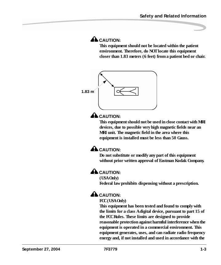
CAUTION:This equipment should not be located within the patient environment. Therefore, do NOT locate this equipment closer than 1.83 meters (6 feet) from a patient bed or chair.
CAUTION:This equipment should not be used in close contact with MRI devices, due to possible very high magnetic fields near an MRI unit. The magnetic field in the area where this equipment is installed must be less than 50 Gauss.
CAUTION:Do not substitute or modify any part of this equipment without prior written approval of Eastman Kodak Company.
CAUTION:(USA Only)Federal law prohibits dispensing without a prescription.
CAUTION:FCC (USA Only)This equipment has been tested and found to comply with the limits for a class A digital device, pursuant to part 15 of the FCC Rules. These limits are designed to provide reasonable protection against harmful interference when the equipment is operated in a commercial environment. This equipment generates, uses, and can radiate radio frequency energy and, if not installed and used in accordance with the
1.83 m
September 27, 2004 7F3779 1-3
Safety and Related Information
instruction manual, may cause harmful interference to radio communications. Operation of this equipment in a residential area is likely to cause harmful interference in which case the user will be required to correct the interference at his own expense.
CAUTION:Do not use isopropyl alcohol to clean the exterior surfaces of this equipment because alcohol can dissolve the exterior paint on the equipment.
CAUTION:Filters are considered to be non-hazardous waste according to the US Environmental Protection Agency Resource Conservation Recovery Act (RCRA). You may dispose of filters in a landfill or incinerator with energy recovery in a municipal, commercial or industrial facility. Contact your state or local government to determine if additional disposal requirements apply.
CAUTION:This equipment contains lead and mercury. The lead is located in the solder on the circuit boards. Mercury is located in the back light of the local panel. Disposal of components containing these materials may be regulated due to environmental considerations. For disposal or recycling information at the end of usable service, please contact your local authorities or visit the Electronics Industry Alliance Web site at: http://www.eiae.org.
LASER WARNING:The equipment uses a 50-milliwatt invisible laser. Laser radiation may be present behind this back panel. The back panel may only be removed by an Authorized Service Provider of Kodak products or Customer’s Qualified Service Personnel. EXPOSURE TO LASER ENERGY MAY RESULT IN EYE DAMAGE.
1-4 7F3779 September 27, 2004
Safety and Related Information
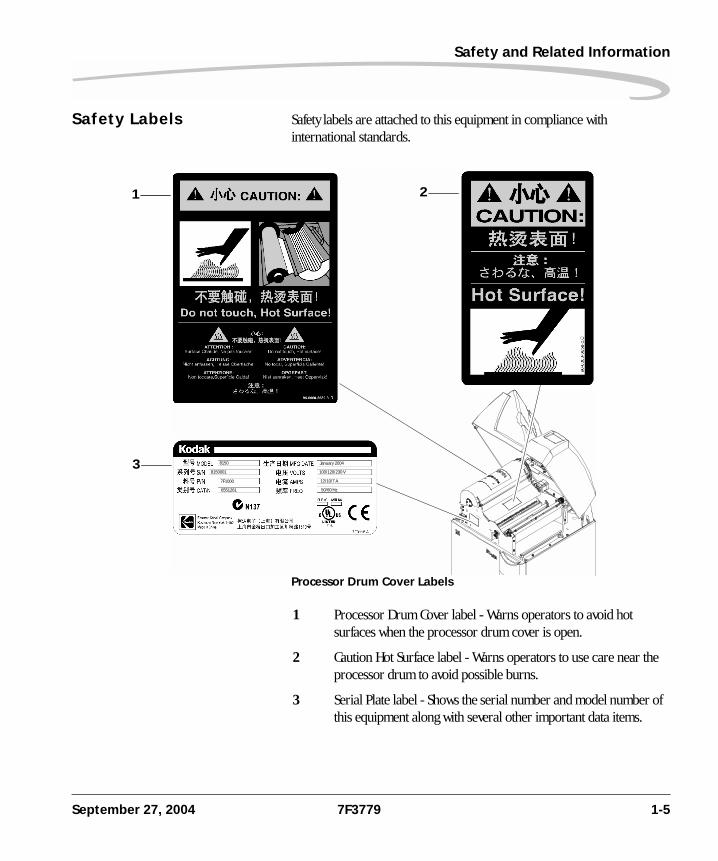
Safety Labels Safety labels are attached to this equipment in compliance with international standards.
Processor Drum Cover Labels
8150
8150001
7F1000
6551261
January 2004
100/120/230 V
12/10/7 A
50/60 Hz
1 2
3
1 Processor Drum Cover label - Warns operators to avoid hot surfaces when the processor drum cover is open.
2 Caution Hot Surface label - Warns operators to use care near the processor drum to avoid possible burns.
3 Serial Plate label - Shows the serial number and model number of this equipment along with several other important data items.
September 27, 2004 7F3779 1-5
Safety and Related Information
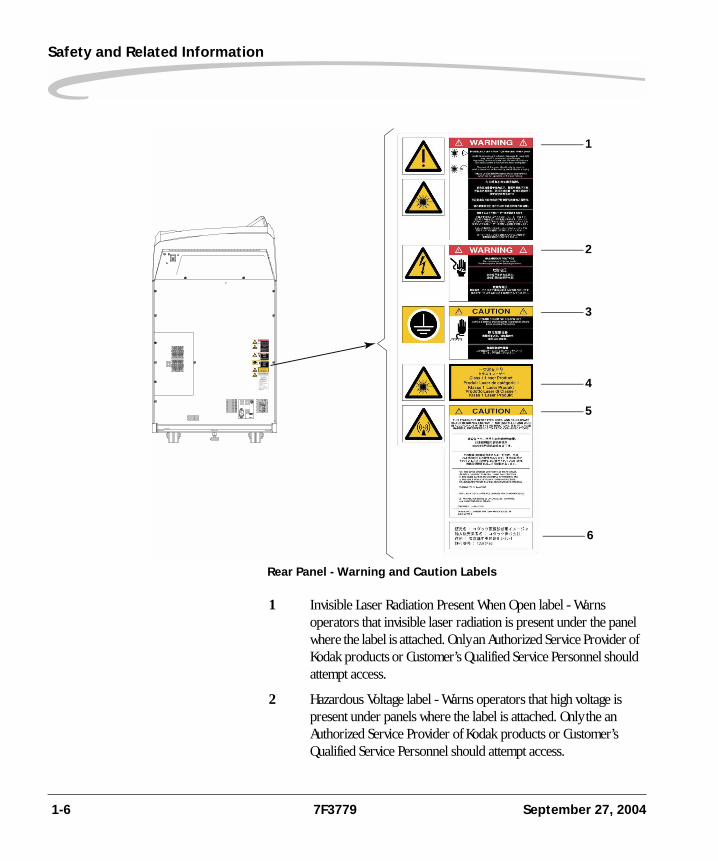
Rear Panel - Warning and Caution Labels
1
2
3
4
5
6
1 Invisible Laser Radiation Present When Open label - Warns operators that invisible laser radiation is present under the panel where the label is attached. Only an Authorized Service Provider of Kodak products or Customer’s Qualified Service Personnel should attempt access.
2 Hazardous Voltage label - Warns operators that high voltage is present under panels where the label is attached. Only the an Authorized Service Provider of Kodak products or Customer’s Qualified Service Personnel should attempt access.
1-6 7F3779 September 27, 2004
Safety and Related Information
3 Static Sensitive Equipment label - Identifies static-sensitive components. Connect a personal grounding strap to appropriate ground before servicing this equipment. Only an Authorized Service Provider of Kodak products may perform service maintenance on this equipment.
4 Class 1 Laser Product - Indicates that this equipment complies with IEC requirements for a Class 1 Laser Product.
5 Radio Frequency Energy - Indicates that this equipment can radiate radio frequency energy. If not installed and used in accordance with the instructions, this equipment may cause harmful interference to radio communications.
6 Japanese Import License - Not safety-related.
September 27, 2004 7F3779 1-7
Safety and Related Information
Safety and Health ComplianceThis equipment has been tested for and complies with the following Safety and Emissions Standards. Certificates of Compliance and Declarations of Conformity have been issued as shown below.
Safety United States
Canada
Europe
21 CFR 1040.10 Class I: FDA CDRH Code of Federal Regulations Title 21 Food and Drugs, Volume 8 - Food and Drugs, Part 1040 - Performance Standards for Light Emitting Products, Section 10 - Laser Products.
FDA 95-415 Premarket Notification 510(K): Regulatory Requirements For Medical Devices.
UL 60950-1: Safety of Information Technology Equipment. (3rd Edition)
UL 60601-1-1: Medical electrical equipment - Part 1: General requirements for safety - Section 1: Collateral standard: Safety requirements for medical electrical systems, Clause 19.
IEC 60825-1: Safety of laser products - Part 1: Equipment classification, requirements and user’s guide.
C22.2 NO 60950-1 CAN/CSA, Safety of Information Technology Equipment, Including Electrical Business Equipment (Gen Instr 1) (UL 1950-95).
IEC 60825-1: Safety of Laser products - Part 1: Equipment classification, requirements and user’s guide.
EN60950-1: Safety of Information Technology Equipment, Including Electrical Business Equipment (2000).
EN60601-1-1: Medical electrical equipment - Part 1: General requirements for safety - Section 1: Collateral standard: Safety requirements for medical electrical systems, Clause 19.
EN60825-1: Safety of laser products - Part 1: Equipment classification, requirements and user's guide.
1-8 7F3779 September 27, 2004
Safety and Related Information
Rest of World
EMC United States
Canada
IEC 60950-1: Safety of information technology equipment.
IEC 60601-1-1: Medical electrical equipment - Part 1: General requirements for safety - Section 1: Collateral standard: Safety requirements for medical electrical systems, Clause 19.
IEC 60825-1: Safety of laser products - Part 1: Equipment classification, requirements and user's guide.
FCC Rules and Regulations, Title 47, Part 15, Subpart B, Class A: Radio Frequency Devices: Unintentional Radiators.
This equipment has been tested and been found to comply with the limits for a Class A digital device pursuant to part 15 of the FCC rules. Those limits are designed to provide reasonable protection against harmful interference in a commercial environment. This equipment generates, uses, and can radiate radio frequency energy and, if not installed and used in accordance with the instruction manual, may cause harmful interference to radio communications. Operation of this equipment in a residential area is likely to cause harmful interference in which case the user will be required to correct the interference at his own expense.
FCC Rules and Regulations, Title 47, Part 15, Subpart C, Radio Frequency Devices: Intentional Radiators. “FCC ID: PA481507E2537"
CAN/CSA-C108.6-M91, Class A: Limits and Methods of Measurement of Electromagnetic Disturbance Characteristics of Industrial, Scientific and Medical (ISM) Radio-Frequency Equipment. (CISPR 11,Class A (EN55011)).
RSS-210, Issue 5:2001, Section 6.2.2(e): Low Power License-exempt Radio Communication Devices (All Frequency Bands), a Spectrum Management and Telecommunications Policy, Radio Standard Specification.
Intentional Radiation “IC: 1016B-8150”
September 27, 2004 7F3779 1-9
Safety and Related Information
Europe
Rest of World
Japan
This Class A digital apparatus complies with Canadian ICES-003.
CET APPAREIL NUM ENRIQUE DE CLASSE A EST CONFORME A LA NORME NMB–003 DU CANADA.
This Class A digital apparatus meets all requirements of the Canadian Interference-Causing Equipment Regulations.
European Telecommunication Standard (ETS) EN300 330: Electromagnetic Compatibility and Radio Spectrum Matters (ERM); Short Range Devices (SRD); Technical Characteristics and Test Methods for Radio Equipment in the Frequency Range 9 kHz to 25 MHz and Inductive loop Systems in the Frequency Range 9 kHz to 30 MHz.
European Telecommunication Standard (ETS) EN300 489-3: Electromagnetic Compatibility and Radio Spectrum Matters (ERM) - Electromagnetic compatibility (EMC) standard for radio equipment and services - Part 3: specific conditions for short-range devices (SRD) operating on frequencies between 9 kHz and 40 GHz.
IEC 60601-1-2: Medical electrical equipment - Part 1-2: General requirements for safety - Collateral standard: Electrical compatibility - Requirements and tests.
VCCI V.3/2001.04: Agreement of Voluntary Control Council for Interference by Information Technology Equipment Technical Requirements.
1-10 7F3779 September 27, 2004
Safety and Related Information
Europe and the Rest of the World
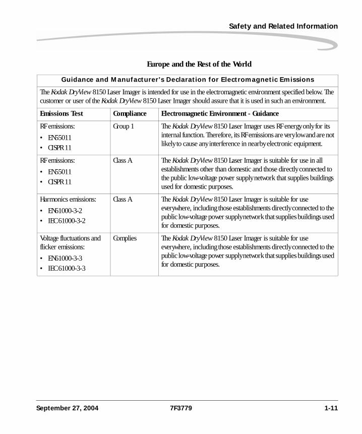
Guidance and Manufacturer’s Declaration for Electromagnetic Emissions
The Kodak DryView 8150 Laser Imager is intended for use in the electromagnetic environment specified below. The customer or user of the Kodak DryView 8150 Laser Imager should assure that it is used in such an environment.
Emissions Test Compliance Electromagnetic Environment - Guidance
RF emissions:
• EN55011• CISPR 11
Group 1 The Kodak DryView 8150 Laser Imager uses RF energy only for its internal function. Therefore, its RF emissions are very low and are not likely to cause any interference in nearby electronic equipment.
RF emissions:
• EN55011• CISPR 11
Class A The Kodak DryView 8150 Laser Imager is suitable for use in all establishments other than domestic and those directly connected to the public low-voltage power supply network that supplies buildings used for domestic purposes.
Harmonics emissions:
• EN61000-3-2• IEC 61000-3-2
Class A The Kodak DryView 8150 Laser Imager is suitable for use everywhere, including those establishments directly connected to the public low-voltage power supply network that supplies buildings used for domestic purposes.
Voltage fluctuations and flicker emissions:
• EN61000-3-3• IEC 61000-3-3
Complies The Kodak DryView 8150 Laser Imager is suitable for use everywhere, including those establishments directly connected to the public low-voltage power supply network that supplies buildings used for domestic purposes.
September 27, 2004 7F3779 1-11
Safety and Related Information
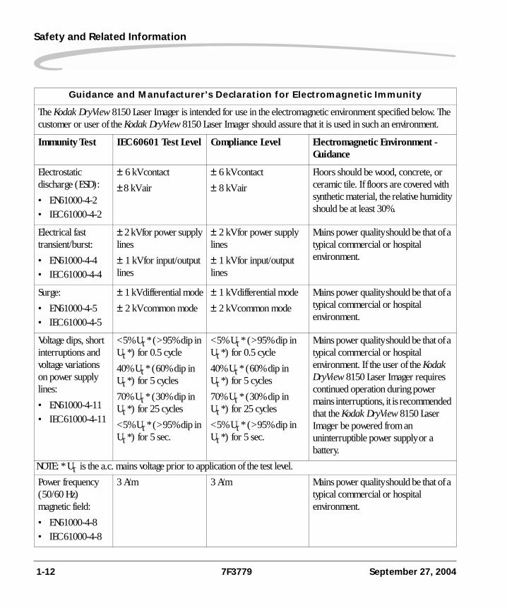
Guidance and Manufacturer’s Declaration for Electromagnetic Immunity
The Kodak DryView 8150 Laser Imager is intended for use in the electromagnetic environment specified below. The customer or user of the Kodak DryView 8150 Laser Imager should assure that it is used in such an environment.
Immunity Test IEC 60601 Test Level Compliance Level Electromagnetic Environment - Guidance
Electrostatic discharge (ESD):
• EN61000-4-2• IEC 61000-4-2
± 6 kV contact
± 8 kV air
± 6 kV contact
± 8 kV air
Floors should be wood, concrete, or ceramic tile. If floors are covered with synthetic material, the relative humidity should be at least 30%.
Electrical fast transient/burst:
• EN61000-4-4• IEC 61000-4-4
± 2 kV for power supply lines
± 1 kV for input/output lines
± 2 kV for power supply lines
± 1 kV for input/output lines
Mains power quality should be that of a typical commercial or hospital environment.
Surge:
• EN61000-4-5• IEC 61000-4-5
± 1 kV differential mode
± 2 kV common mode
± 1 kV differential mode
± 2 kV common mode
Mains power quality should be that of a typical commercial or hospital environment.
Voltage dips, short interruptions and voltage variations on power supply lines:
• EN61000-4-11• IEC 61000-4-11
<5% Uτ * (>95% dip in Uτ *) for 0.5 cycle
40% Uτ * (60% dip in Uτ *) for 5 cycles
70% Uτ * (30% dip in Uτ *) for 25 cycles
<5% Uτ * (>95% dip in Uτ *) for 5 sec.
<5% Uτ * (>95% dip in Uτ *) for 0.5 cycle
40% Uτ * (60% dip in Uτ *) for 5 cycles
70% Uτ * (30% dip in Uτ *) for 25 cycles
<5% Uτ * (>95% dip in Uτ *) for 5 sec.
Mains power quality should be that of a typical commercial or hospital environment. If the user of the Kodak DryView 8150 Laser Imager requires continued operation during power mains interruptions, it is recommended that the Kodak DryView 8150 Laser Imager be powered from an uninterruptible power supply or a battery.
NOTE: * Uτ is the a.c. mains voltage prior to application of the test level.
Power frequency (50/60 Hz) magnetic field:
• EN61000-4-8• IEC 61000-4-8
3 A/m 3 A/m Mains power quality should be that of a typical commercial or hospital environment.
1-12 7F3779 September 27, 2004
Safety and Related Information
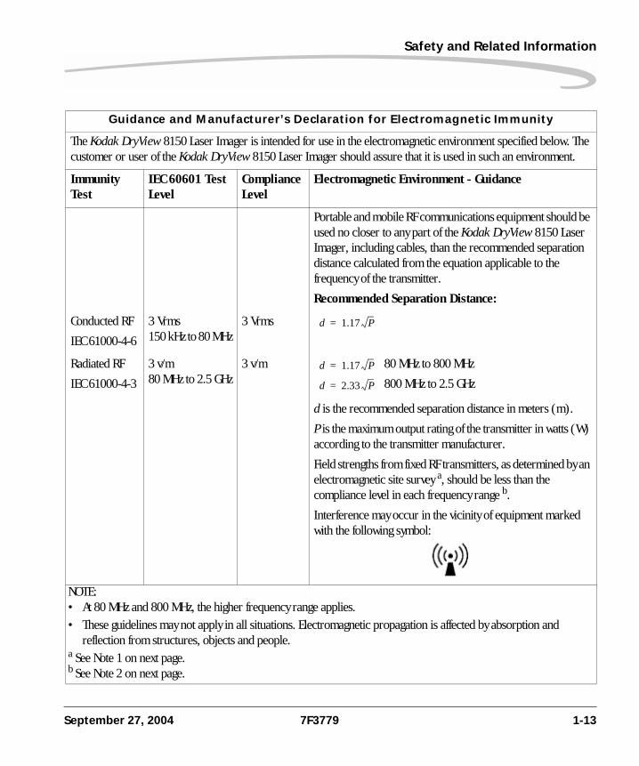
Guidance and Manufacturer’s Declaration for Electromagnetic Immunity
The Kodak DryView 8150 Laser Imager is intended for use in the electromagnetic environment specified below. The customer or user of the Kodak DryView 8150 Laser Imager should assure that it is used in such an environment.
Immunity Test
IEC 60601 Test Level
Compliance Level
Electromagnetic Environment - Guidance
Portable and mobile RF communications equipment should be used no closer to any part of the Kodak DryView 8150 Laser Imager, including cables, than the recommended separation distance calculated from the equation applicable to the frequency of the transmitter.
Recommended Separation Distance:
Conducted RF
IEC 61000-4-6
3 Vrms150 kHz to 80 MHz
3 Vrms
Radiated RF
IEC 61000-4-3
3 v/m80 MHz to 2.5 GHz
3 v/m 80 MHz to 800 MHz
800 MHz to 2.5 GHz
d is the recommended separation distance in meters (m).
P is the maximum output rating of the transmitter in watts (W) according to the transmitter manufacturer.
Field strengths from fixed RF transmitters, as determined by an electromagnetic site survey a, should be less than the compliance level in each frequency range b.
Interference may occur in the vicinity of equipment marked with the following symbol:
NOTE: • At 80 MHz and 800 MHz, the higher frequency range applies.• These guidelines may not apply in all situations. Electromagnetic propagation is affected by absorption and
reflection from structures, objects and people.a See Note 1 on next page.b See Note 2 on next page.
d 1.17 P=
d 1.17 P=
d 2.33 P=
September 27, 2004 7F3779 1-13
Safety and Related Information
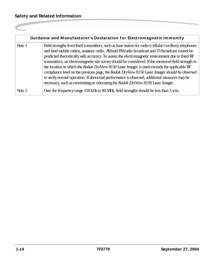
Note 1 Field strengths from fixed transmitters, such as base station for radio (cellular/cordless) telephones and land mobile radios, amateur radio, AM and FM radio broadcast and TV broadcast cannot be predicted theoretically with accuracy. To assess the electromagnetic environment due to fixed RF transmitters, an electromagnetic site survey should be considered. If the measured field strength in the location in which the Kodak DryView 8150 Laser Imager is used exceeds the applicable RF compliance level on the previous page, the Kodak DryView 8150 Laser Imager should be observed to verify normal operation. If abnormal performance is observed, additional measures may be necessary, such as reorienting or relocating the Kodak DryView 8150 Laser Imager.
Note 2 Over the frequency range 150 kHz to 80 MHz, field strengths should be less than 3 v/m.
Guidance and Manufacturer’s Declaration for Electromagnetic Immunity
1-14 7F3779 September 27, 2004
Safety and Related Information
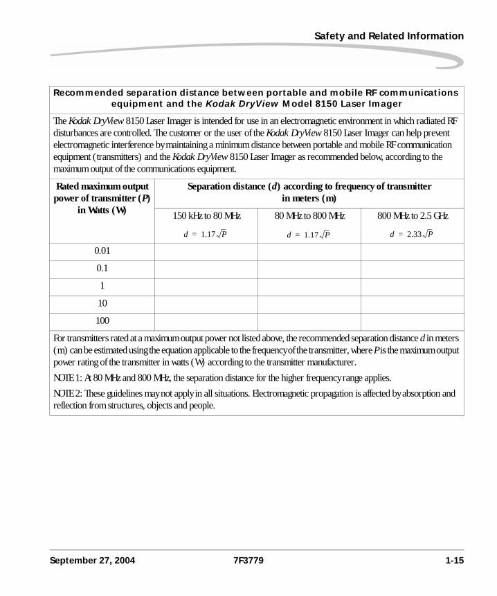
Recommended separation distance between portable and mobile RF communications equipment and the Kodak DryView Model 8150 Laser Imager
The Kodak DryView 8150 Laser Imager is intended for use in an electromagnetic environment in which radiated RF disturbances are controlled. The customer or the user of the Kodak DryView 8150 Laser Imager can help prevent electromagnetic interference by maintaining a minimum distance between portable and mobile RF communication equipment (transmitters) and the Kodak DryView 8150 Laser Imager as recommended below, according to the maximum output of the communications equipment.
Rated maximum output power of transmitter (P)
in Watts (W)
Separation distance (d) according to frequency of transmitter in meters (m)
150 kHz to 80 MHz 80 MHz to 800 MHz 800 MHz to 2.5 GHz
0.01
0.1
1
10
100
For transmitters rated at a maximum output power not listed above, the recommended separation distance d in meters (m) can be estimated using the equation applicable to the frequency of the transmitter, where P is the maximum output power rating of the transmitter in watts (W) according to the transmitter manufacturer.
NOTE 1: At 80 MHz and 800 MHz, the separation distance for the higher frequency range applies.
NOTE 2: These guidelines may not apply in all situations. Electromagnetic propagation is affected by absorption and reflection from structures, objects and people.
d 1.17 P= d 1.17 P= d 2.33 P=
September 27, 2004 7F3779 1-15
Safety and Related Information
EU Directives 93/42/EEC Title: Council Directive Concerning Medical Devices.99/05/EEC Title: Council Directive Concerning Radio and Telecommunications Terminal Equipment.73/23/EEC Title: Council Directive on the Harmonization of the Laws of Member States Relating to Electrical Equipment Designed for Use within Certain Voltage Limits.89/336/EEC Title: Council Directive on the Approximation of the Laws of the Member States Relating to Electromagnetic Compatibility.
1-16 7F3779 September 27, 2004
Safety and Related Information
CE Marking Documents concerning the conformance of this product to Council Directive 93/42/EEC of 14 June 1993 concerning Medical Devices can be obtained from the Eastman Kodak Company, Health Imaging Systems European Representative at:
Kodak GmbHProduct Safety70323 StuttgartGermanyPhone: ++49 711 406 2993Fax: ++49 711 406 3513
September 27, 2004 7F3779 1-17
Safety and Related Information
Note The information contained herein is based on the experience and knowledge relating to the subject matter gained by Eastman Kodak Company prior to publication. No patent license is granted by this information. Eastman Kodak Company reserves the right to change this information without notice and makes no warranty, express or implied, with respect to this information. Kodak shall not be liable for any loss or damage, including consequential or special damages, resulting from the use of this information, even if loss or damage is caused by Kodak's negligence or other fault.
1-18 7F3779 September 27, 2004


Eastman Kodak Company343 State StreetRochester, NY 14650
© Eastman Kodak Company, 2004

TI READER MODULE
HF Reader System Series 6000 S6350 Midrange Reader Module
RI-STU-TRDC-02
Reference Guide
1
1
1-06-21-700 September 2002 A TEXAS INSTRUMENTS TECHNOLOGY
September 2002 S6350 Midrange Reader Module - Reference Guide
2
Third Edition - September 2002
This is the third edition of this manual. It describes the following product:
S6350 Midrange Reader Module RI-STU-TRDC-02
Firmware Version 1.44 Major Changes: - Addition of Baud Rate Configuration Command - Note to ISO Read Multiple Blocks Command
Texas Instruments (TI) reserves the right to make changes to its products or services or to discontinue any product or service at any time without notice. TI provides customer assistance in various technical areas, but does not have full access to data concerning the use and applications of customer’s products
Therefore, TI assumes no liability and is not responsible for customer applications or product or software design or performance relating to systems or applications incorporating TI products. In addition, TI assumes no liability and is not responsible for infringement of patents and/or any other intellectual or industrial property rights of third parties, which may result from assistance provided by TI.
TI products are not designed, intended, authorized or warranted to be suitable for life support applications or any other life critical applications which could involve potential risk of death, personal injury or severe property or environmental damage.
The TIRIS and TI-RFid logo, the words TIRIS, TI-RFid, TI-RFID and Tag-it are trademarks or registered trademarks of Texas Instruments Incorporated (TI).
Copyright © 2002 Texas Instruments Incorporated (TI).
This document may be downloaded onto a computer, stored and duplicated as necessary to support the use of the related TI products. Any other type of duplication, circulation or storage on data carriers in any manner not authorized by TI represents a violation of the applicable copyright laws and shall be prosecuted.
3
Read This First
About This Manual This reference guide for the S6350 Midrange Reader Module is designed for use by TI customers who are engineers experienced with RFID Systems and Radio Frequency Identification Devices (RFID).
Regulatory, safety and warranty notices that must be followed are provided in Chapter 4.
Conventions
The following pictograms and designations are used in these operating instructions:
CAUTION:
This indicates information on conditions, which must be met, or a procedure, which must be followed, which if not needed could cause permanent damage to the system.
Note:
Indicates conditions, which must be met, or procedures which must be followed, to ensure proper functioning.
Preface
September 2002 S6350 Midrange Reader Module - Reference Guide
4
If You Need Assistance
For more information, please contact the sales office or distributor nearest you. This contact information can be found on our web site at:
http://www.ti-rfid.com
Terms and Abbreviations
The terms and abbreviations used in this manual can be found in the Terms and Abbreviations Manual, document number 11-03-21-002. This manual can be found in the document center on our web site at:
http://www.ti-rfid.com
Numerical Representations
Unless otherwise noted, numbers are represented as decimal.
Hexadecimal numbers are represented with the suffix hex, e.g. A5F1hex
Binary numbers are represented with the suffix 2, e.g. 10112
Byte representations: the least significant bit (lsb) is bit 0 and the most significant bit (msb) is bit 7.
September 2002 S6350 Midrange Reader Module - Reference Guide
5
Document Overview
Chapter 1: Introduction ............................................................................................................. 6
1.1 Description ......................................................................................................... 7 1.2 Programming Interface ...................................................................................... 7
Chapter 2: Hardware Description............................................................................................. 8 2.1 General Specification......................................................................................... 9
2.1.1 Functional Requirements............................................................................. 9 2.1.2 Power Supply............................................................................................... 9 2.1.3 Output Power ............................................................................................... 9 2.1.4 RF Physical Layer...................................................................................... 10 2.1.5 Required Antenna Parameters .................................................................. 10 2.1.6 Input / output pins (CN1 pins 3 and 4) ....................................................... 10 2.1.7 Baseband receiver ..................................................................................... 11 2.1.8 Connector Details ...................................................................................... 12 2.1.9 16-pin Header Connector CN1 .................................................................. 12 2.1.10 RI-STU-TRDC-02 (CN1) Pin Assignments............................................... 13
2.2 Mechanical Specifications................................................................................ 14 2.2.1 RI-STU-TRDC-02 with 16-pin Straight Header Connector ........................ 14
Chapter 3: Reader Protocol .................................................................................................... 15 3.1 Serial Protocol Definition.................................................................................. 16
3.1.1 Request Packet Format (Host to Reader) ................................................. 16 3.1.2 Response Packet Format (Reader to Host) .............................................. 17 3.1.3 Command Flags Request .......................................................................... 17 3.1.4 Command Flags Response ....................................................................... 18 3.1.5 BCC ........................................................................................................... 18 3.1.6 Example Request Packet .......................................................................... 18
3.2 Command Definitions....................................................................................... 19 3.2.1 Tag-it HF Command Definitions ................................................................ 19 3.2.2 Miscellaneous Commands......................................................................... 22 3.2.3 ISO/IEC 15693 Part 3 Transmission Protocol ........................................... 26 3.2.3.1 ISO/IEC 15693-3 Command Codes ....................................................... 26 3.2.3.2 Request/Response Packet Format for ISO/IEC 15693-3....................... 27 3.2.3.3 Mandatory Commands ........................................................................... 30 3.2.3.4 Optional Commands ............................................................................... 32
Chapter 4: Regulatory and Warrenty Notices ....................................................................... 42 4.1 Regulatory Notes ............................................................................................. 43 4.2 FCC Notices (U.S.A.)....................................................................................... 43 4.3 R&TTE Conformity (Europe)........................................................................... 43 4.4 Warranty and Liability ...................................................................................... 43
Appendix A: Downloading Data to FLASH Memory ............................................................. 44 Appendix B: Error Codes......................................................................................................... 45
September 2002 S6350 Midrange Reader Module - Reference Guide
6
Introduction
Topic Page 1.1 Product Description............................................................................................ 7 1.2 Programming Interface ...................................................................................... 7
Chapter 1
September 2002 S6350 Midrange Reader Module - Reference Guide
7
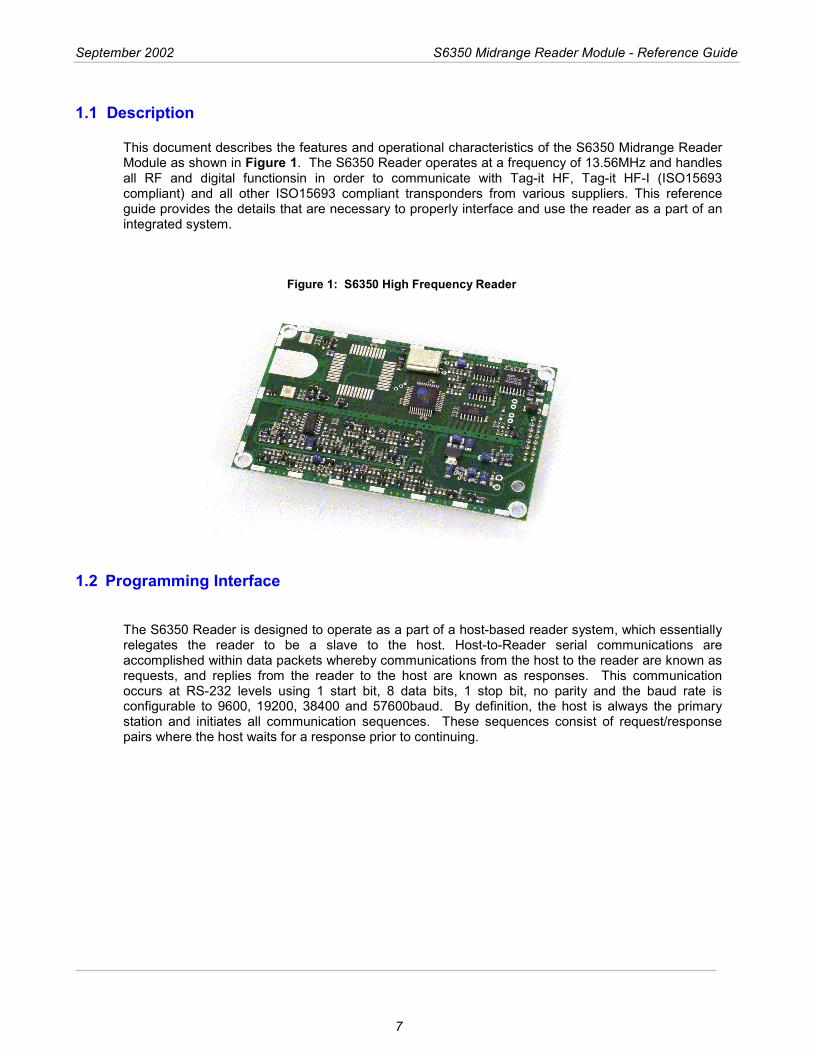
1.1 Description This document describes the features and operational characteristics of the S6350 Midrange Reader Module as shown in Figure 1. The S6350 Reader operates at a frequency of 13.56MHz and handles all RF and digital functionsin in order to communicate with Tag-it HF, Tag-it HF-I (ISO15693 compliant) and all other ISO15693 compliant transponders from various suppliers. This reference guide provides the details that are necessary to properly interface and use the reader as a part of an integrated system.
Figure 1: S6350 High Frequency Reader
1.2 Programming Interface
The S6350 Reader is designed to operate as a part of a host-based reader system, which essentially relegates the reader to be a slave to the host. Host-to-Reader serial communications are accomplished within data packets whereby communications from the host to the reader are known as requests, and replies from the reader to the host are known as responses. This communication occurs at RS-232 levels using 1 start bit, 8 data bits, 1 stop bit, no parity and the baud rate is configurable to 9600, 19200, 38400 and 57600baud. By definition, the host is always the primary station and initiates all communication sequences. These sequences consist of request/response pairs where the host waits for a response prior to continuing.
8
Hardware Description
Topic Page 2.1 General Specification........................................................................................ 9
2.1.1 Functional Requirements............................................................................. 9 2.1.2 Power Supply............................................................................................... 9 2.1.3 Output Power ............................................................................................... 9 2.1.4 RF Physical Layer...................................................................................... 10 2.1.5 Required Antenna Parameters .................................................................. 10 2.1.6 Input / output pins (CN1 pins 3 and 4) ....................................................... 10 2.1.7 Baseband receiver ..................................................................................... 11 2.1.8 Connector Details ...................................................................................... 12 2.1.9 16-pin Header Connector CN1 .................................................................. 12 2.1.10 RI-STU-TRDC-02 (CN1) Pin Assignments............................................... 13
2.2 Mechanical Specifications................................................................................ 14 2.2.1 RI-STU-TRDC-02 with 16-pin Straight Header Connector ........................ 14
Chapter 2
September 2002 S6350 Midrange Reader Module - Reference Guide
9
2.1 General Specification This chapter describes the electrical and mechanical specifications of the S6350 Midrange Reader Module (RI-STU-TRDC-02). Operating at a frequency of 13.56 MHz, this low profile, low power device is designed to be easily integrated into many systems as an embedded device. All reader I/O is accomplished through the use of a 16-pin header connector (labeled as CN1), to include all communication, which is asynchronous RS232 as controlled by a host system.
2.1.1 Functional Requirements
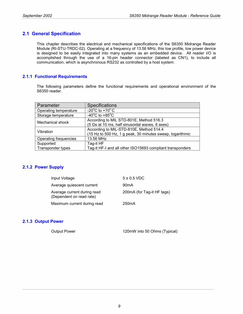
The following parameters define the functional requirements and operational environment of the S6350 reader. Parameter Specifications Operating temperature -20oC to +70o C Storage temperature -40oC to +85oC
Mechanical shock According to MIL STD-801E, Method 516.3 (5 Gs at 10 ms, half sinusoidal waves, 6 axes)
Vibration According to MIL-STD-810E, Method 514.4 (15 Hz to 500 Hz, 1 g peak, 30 minutes sweep, logarithmic
Operating frequencies 13.56 MHz Supported Transponder types
Tag-it HF Tag-it HF-I and all other ISO15693 compliant transponders
2.1.2 Power Supply
Input Voltage 5 ± 0.5 VDC
Average quiescent current 90mA
Average current during read 200mA (for Tag-it HF tags) (Dependent on read rate)
Maximum current during read 250mA
2.1.3 Output Power
Output Power 120mW into 50 Ohms (Typical)
September 2002 S6350 Midrange Reader Module - Reference Guide
10
2.1.4 RF Physical Layer
Reader to Transponder: 10% - 30% (nominally set at 20%) or 100% modulation (set by software) - ASK.
Data Coding Mode: 1 / 4 or 1 / 256.
Transponder to Reader: FSK / Fast Data Rate.
2.1.5 Required Antenna Parameters
Impedance 50Ω ± 5Ω at 13.56 MHz Loaded Q 10 < Q < 30
Note:
As no standard antenna is provided by Texas Instruments for the S6350 reader, the noted required antenna parameters must be closely followed by the integrator for the reader to operate properly.
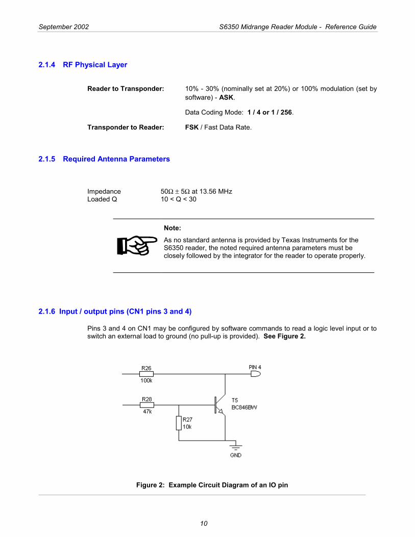
2.1.6 Input / output pins (CN1 pins 3 and 4)
Pins 3 and 4 on CN1 may be configured by software commands to read a logic level input or to switch an external load to ground (no pull-up is provided). See Figure 2.
Figure 2: Example Circuit Diagram of an IO pin
September 2002 S6350 Midrange Reader Module - Reference Guide
11
When used as a switch to ground the following ratings should not be exceeded: Maximum voltage 20V Maximum current 50mA
CAUTION:
Exceeding this Voltage and Current limit could cause permanent damage to the reader.
Note:
That if an output has been set by a software command the state will always read back as a logic 0.
2.1.7 Baseband receiver
Minimum data pulse width 5µs Maximum data pulse width 500µs Typical settling time 50µs from the first transition
Note:
The receiver extracts the mean level of the incoming data stream as a reference. This takes approximately 50µs; therefore the data output of the receiver is not valid until after this time.
September 2002 S6350 Midrange Reader Module - Reference Guide
12
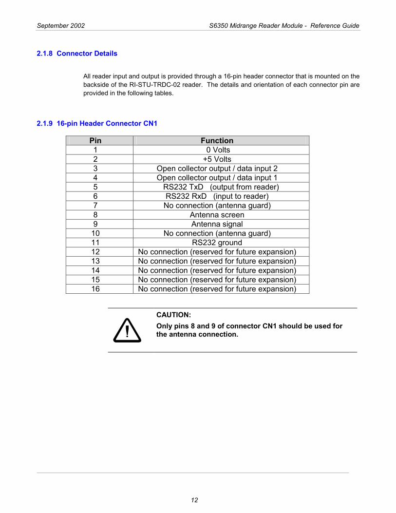
2.1.8 Connector Details
All reader input and output is provided through a 16-pin header connector that is mounted on the backside of the RI-STU-TRDC-02 reader. The details and orientation of each connector pin are provided in the following tables.
2.1.9 16-pin Header Connector CN1
Pin Function 1 0 Volts 2 +5 Volts 3 Open collector output / data input 2 4 Open collector output / data input 1 5 RS232 TxD (output from reader) 6 RS232 RxD (input to reader) 7 No connection (antenna guard) 8 Antenna screen 9 Antenna signal
10 No connection (antenna guard) 11 RS232 ground 12 No connection (reserved for future expansion) 13 No connection (reserved for future expansion) 14 No connection (reserved for future expansion) 15 No connection (reserved for future expansion) 16 No connection (reserved for future expansion)
CAUTION: Only pins 8 and 9 of connector CN1 should be used for the antenna connection.
September 2002 S6350 Midrange Reader Module - Reference Guide
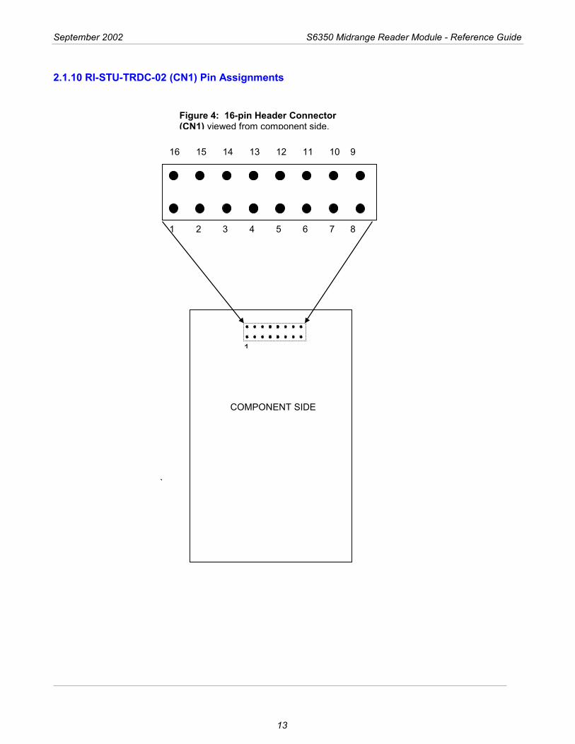
2.1.10 RI-STU-TRDC-02 (CN1) Pin Assignments
1 2 3 4 5 6 7 8
16 15 14 13 12 11 10 9
Figure 4: 16-pin Header Connector (CN1) viewed from component side.
13
`
COMPONENT SIDE
1
September 2002 S6350 Midrange Reader Module - Reference Guide
14
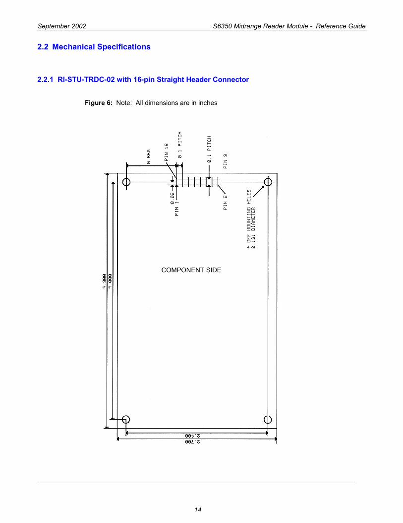
2.2 Mechanical Specifications
2.2.1 RI-STU-TRDC-02 with 16-pin Straight Header Connector
Figure 6: Note: All dimensions are in inches
COMPONENT SIDE
15
Reader Protocol
Topic Page 3.1 Serial Protocol Definition ................................................................................. 16
3.1.1 Request Packet Format (Host to Reader) ................................................. 16 3.1.2 Response Packet Format (Reader to Host) .............................................. 17 3.1.3 Command Flags Request .......................................................................... 17 3.1.4 Command Flags Response ....................................................................... 18 3.1.5 BCC ........................................................................................................... 18 3.1.6 Example Request Packet .......................................................................... 18
3.2 Command Definitions ...................................................................................... 19 3.2.1 Tag-it™ HF Command Definitions............................................................. 19 3.2.2 Miscellaneous Commands......................................................................... 22 3.2.3 ISO/IEC FCD 15693 Part 3 Transmission Protocol................................... 26 3.2.3.1 ISO/IEC 15693-3 Command Codes ....................................................... 26 3.2.3.2 Request/Response Packet Format for ISO/IEC 15693-3....................... 27 3.2.3.3 Mandatory Commands ........................................................................... 30 3.2.3.4 Optional Commands ............................................................................... 32
Chapter 3
September 2002 S6350 Midrange Reader Module - Reference Guide
16
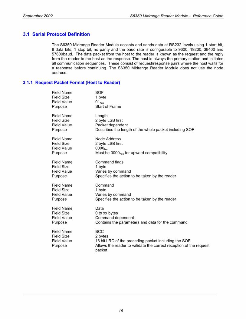
3.1 Serial Protocol Definition
The S6350 Midrange Reader Module accepts and sends data at RS232 levels using 1 start bit, 8 data bits, 1 stop bit, no parity and the baud rate is configurable to 9600, 19200, 38400 and 57600baud. The data packet from the host to the reader is known as the request and the reply from the reader to the host as the response. The host is always the primary station and initiates all communication sequences. These consist of request/response pairs where the host waits for a response before continuing. The S6350 Midrange Reader Module does not use the node address.
3.1.1 Request Packet Format (Host to Reader)
Field Name SOF Field Size 1 byte Field Value 01hex Purpose Start of Frame Field Name Length Field Size 2 byte LSB first Field Value Packet dependent Purpose Describes the length of the whole packet including SOF Field Name Node Address Field Size 2 byte LSB first Field Value 0000hex Purpose Must be 0000hex for upward compatibility Field Name Command flags Field Size 1 byte Field Value Varies by command Purpose Specifies the action to be taken by the reader Field Name Command Field Size 1 byte Field Value Varies by command Purpose Specifies the action to be taken by the reader Field Name Data Field Size 0 to xx bytes Field Value Command dependent Purpose Contains the parameters and data for the command Field Name BCC Field Size 2 bytes Field Value 16 bit LRC of the preceding packet including the SOF Purpose Allows the reader to validate the correct reception of the request
packet
September 2002 S6350 Midrange Reader Module - Reference Guide
17
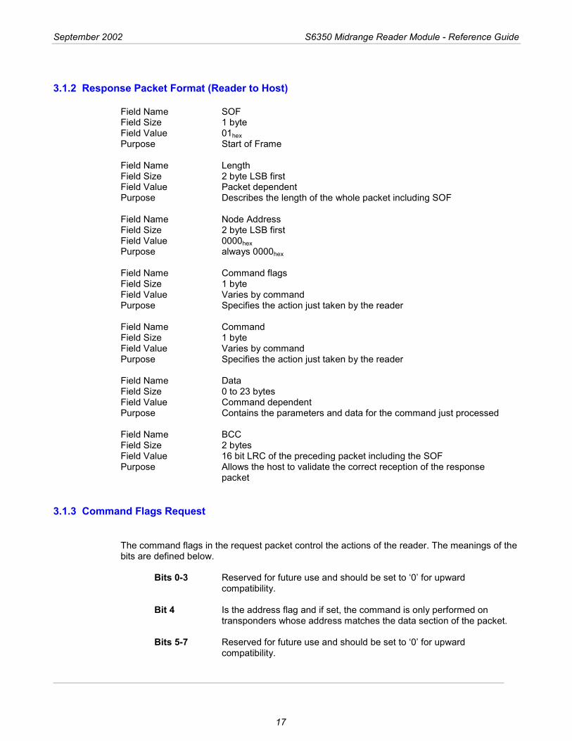
3.1.2 Response Packet Format (Reader to Host)
Field Name SOF Field Size 1 byte Field Value 01hex Purpose Start of Frame Field Name Length Field Size 2 byte LSB first Field Value Packet dependent Purpose Describes the length of the whole packet including SOF Field Name Node Address Field Size 2 byte LSB first Field Value 0000hex Purpose always 0000hex Field Name Command flags Field Size 1 byte Field Value Varies by command Purpose Specifies the action just taken by the reader Field Name Command Field Size 1 byte Field Value Varies by command Purpose Specifies the action just taken by the reader Field Name Data Field Size 0 to 23 bytes Field Value Command dependent Purpose Contains the parameters and data for the command just processed Field Name BCC Field Size 2 bytes Field Value 16 bit LRC of the preceding packet including the SOF Purpose Allows the host to validate the correct reception of the response
packet
3.1.3 Command Flags Request
The command flags in the request packet control the actions of the reader. The meanings of the bits are defined below.
Bits 0-3 Reserved for future use and should be set to ‘0’ for upward compatibility.
Bit 4 Is the address flag and if set, the command is only performed on
transponders whose address matches the data section of the packet.
Bits 5-7 Reserved for future use and should be set to ‘0’ for upward compatibility.
September 2002 S6350 Midrange Reader Module - Reference Guide
18
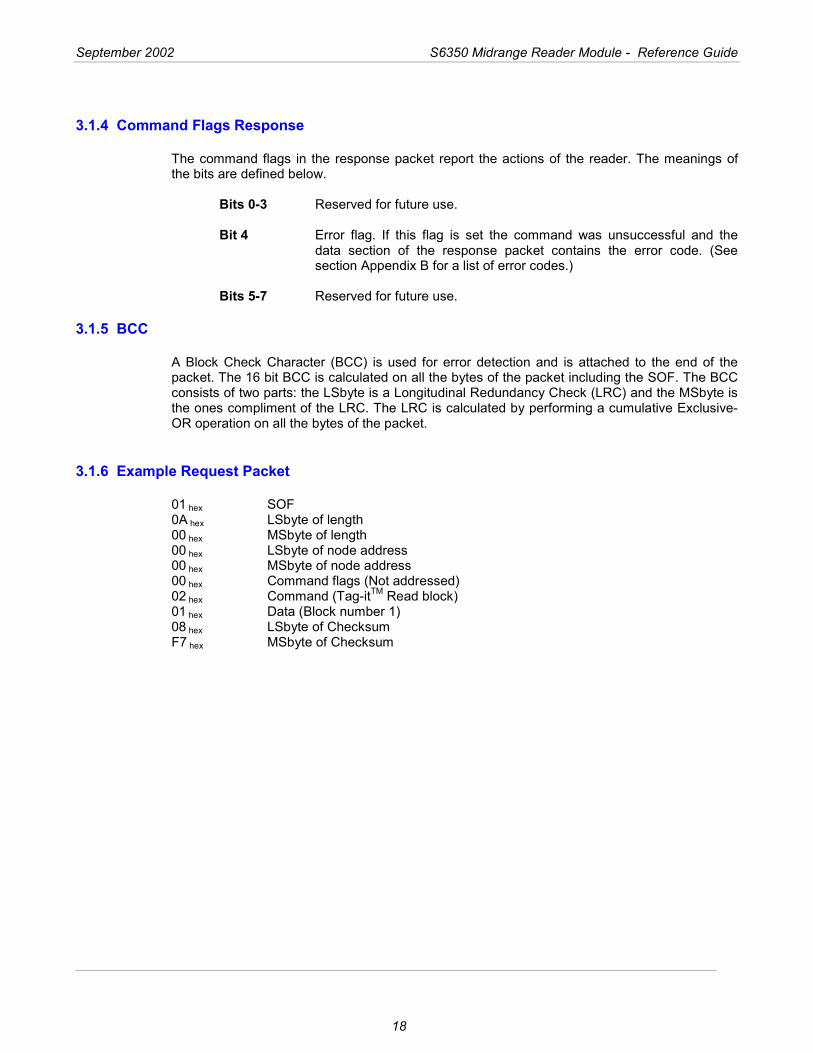
3.1.4 Command Flags Response
The command flags in the response packet report the actions of the reader. The meanings of the bits are defined below.
Bits 0-3 Reserved for future use. Bit 4 Error flag. If this flag is set the command was unsuccessful and the
data section of the response packet contains the error code. (See section Appendix B for a list of error codes.)
Bits 5-7 Reserved for future use.
3.1.5 BCC
A Block Check Character (BCC) is used for error detection and is attached to the end of the packet. The 16 bit BCC is calculated on all the bytes of the packet including the SOF. The BCC consists of two parts: the LSbyte is a Longitudinal Redundancy Check (LRC) and the MSbyte is the ones compliment of the LRC. The LRC is calculated by performing a cumulative Exclusive-OR operation on all the bytes of the packet.
3.1.6 Example Request Packet
01 hex SOF 0A hex LSbyte of length 00 hex MSbyte of length 00 hex LSbyte of node address 00 hex MSbyte of node address 00 hex Command flags (Not addressed) 02 hex Command (Tag-itTM Read block) 01 hex Data (Block number 1) 08 hex LSbyte of Checksum F7 hex MSbyte of Checksum

September 2002 S6350 Midrange Reader Module - Reference Guide
19
3.2 Command Definitions
3.2.1 Tag-it HF Command Definitions
Command Function (Tag-it HF) Command Code Read Single Non-addressed & Addressed Block 02hex Write Single Non-addressed & Addressed Block 03hex Lock Single Non-addressed & Addressed Block 04hex Read Transponder Details 05hex Special Read Block Command 0Fhex
Read Block Command (02hex) Reads a single block of data from a Tag-it HF transponder. If the address flag is set, the address forms the first part of the data section (LSbyte first), followed by a single byte containing the block number to be read. If the address flag is clear the data section only contains the block number. Example Read block 3 of a Tag-it HF transponder whose address is 0134A4D5hex Request packet 01 0E 00 00 00 10 02 D5 A4 34 01 03 5A A5hex The response packet is similar to the request packet, with the data section containing the data received from the transponder (LSbyte first) followed by a single byte indicating the lock status and then another single byte containing the block address. The two LSB’s of the lock status byte reflect the two lock bits in the transponder. Example Response packet 01 0F 00 00 00 00 02 33 22 11 00 00 03 0F F0 hex 00112233hex read from unlocked block 3 of a Tag-itTM transponder.
Write Block Command (03hex) Writes a single block of data to a Tag-it HF transponder. If the address flag is set, the address forms the first part of the data section, followed by a single byte containing the block number to be written. The data to be written follows the block number. If the address flag is clear the data section only contains the block byte and the data to be written. Example Write Block 4 of a Tag-it HF transponder whose address is 000134A4hex with data 01234567hex Request packet 01 12 00 00 00 10 03 A4 34 01 00 04 67 45 23 01 95 6Ahex
September 2002 S6350 Midrange Reader Module - Reference Guide
20
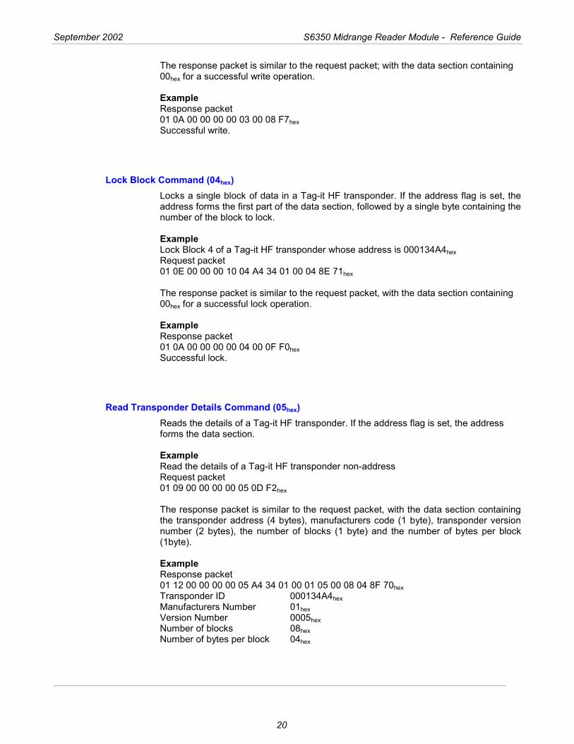
The response packet is similar to the request packet; with the data section containing 00hex for a successful write operation. Example Response packet 01 0A 00 00 00 00 03 00 08 F7hex Successful write.
Lock Block Command (04hex) Locks a single block of data in a Tag-it HF transponder. If the address flag is set, the address forms the first part of the data section, followed by a single byte containing the number of the block to lock. Example Lock Block 4 of a Tag-it HF transponder whose address is 000134A4hex Request packet 01 0E 00 00 00 10 04 A4 34 01 00 04 8E 71hex
The response packet is similar to the request packet, with the data section containing 00hex for a successful lock operation. Example Response packet 01 0A 00 00 00 00 04 00 0F F0hex Successful lock.
Read Transponder Details Command (05hex) Reads the details of a Tag-it HF transponder. If the address flag is set, the address forms the data section. Example Read the details of a Tag-it HF transponder non-address Request packet 01 09 00 00 00 00 05 0D F2hex The response packet is similar to the request packet, with the data section containing the transponder address (4 bytes), manufacturers code (1 byte), transponder version number (2 bytes), the number of blocks (1 byte) and the number of bytes per block (1byte). Example Response packet 01 12 00 00 00 00 05 A4 34 01 00 01 05 00 08 04 8F 70hex Transponder ID 000134A4hex Manufacturers Number 01hex Version Number 0005hex Number of blocks 08hex Number of bytes per block 04hex
September 2002 S6350 Midrange Reader Module - Reference Guide
21
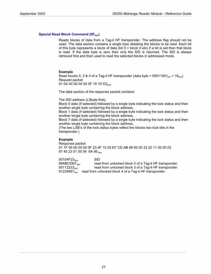
Special Read Block Command (0Fhex) Reads blocks of data from a Tag-it HF transponder. The address flag should not be used. The data section contains a single byte detailing the blocks to be read. Each bit of this byte represents a block of data (bit 0 = block 0 etc) if a bit is set then that block is read. If the data byte is zero then only the SID is returned. The SID is always retrieved first and then used to read the selected blocks in addressed mode. Example Read blocks 0, 3 & 4 of a Tag-it HF transponder (data byte = 00011001bin = 19hex) Request packet 01 0A 00 00 00 00 0F 19 1D E2hex The data section of the response packet contains: The SID address (LSbyte first), Block 0 data (if selected) followed by a single byte indicating the lock status and then another single byte containing the block address, Block 1 data (if selected) followed by a single byte indicating the lock status and then another single byte containing the block address, Block 7 data (if selected) followed by a single byte indicating the lock status and then another single byte containing the block address, (The two LSB’s of the lock status bytes reflect the blocks two lock bits in the transponder.) Example Response packet 01 1F 00 00 00 00 0F 23 4F 10 00 EF CD AB 89 00 00 33 22 11 00 00 03 67 45 23 01 00 04 6A 95 hex 00104F23hex SID 89ABCDEFhex read from unlocked block 0 of a Tag-it HF transponder. 00112233hex read from unlocked block 3 of a Tag-it HF transponder. 01234567hex read from unlocked block 4 of a Tag-it HF transponder.
September 2002 S6350 Midrange Reader Module - Reference Guide
22
3.2.2 Miscellaneous Commands
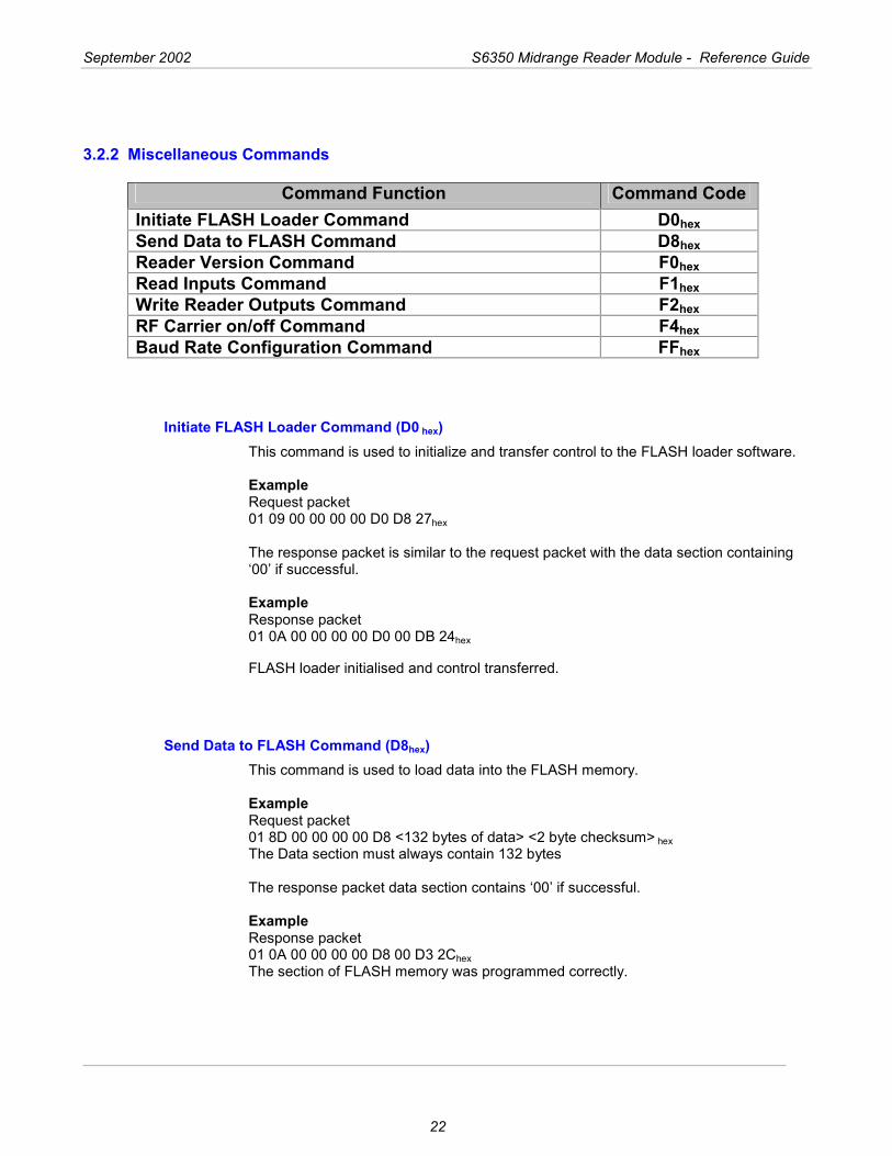
Command Function Command Code Initiate FLASH Loader Command D0hex Send Data to FLASH Command D8hex Reader Version Command F0hex Read Inputs Command F1hex Write Reader Outputs Command F2hex RF Carrier on/off Command F4hex Baud Rate Configuration Command FFhex
Initiate FLASH Loader Command (D0 hex) This command is used to initialize and transfer control to the FLASH loader software. Example Request packet 01 09 00 00 00 00 D0 D8 27hex The response packet is similar to the request packet with the data section containing ‘00’ if successful. Example Response packet 01 0A 00 00 00 00 D0 00 DB 24hex
FLASH loader initialised and control transferred.
Send Data to FLASH Command (D8hex) This command is used to load data into the FLASH memory. Example Request packet 01 8D 00 00 00 00 D8 <132 bytes of data> <2 byte checksum> hex The Data section must always contain 132 bytes The response packet data section contains ‘00’ if successful. Example Response packet 01 0A 00 00 00 00 D8 00 D3 2Chex The section of FLASH memory was programmed correctly.
September 2002 S6350 Midrange Reader Module - Reference Guide
23
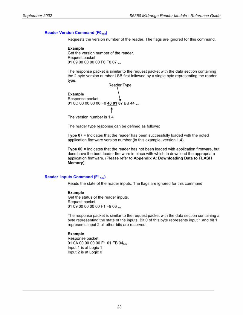
Reader Version Command (F0hex) Requests the version number of the reader. The flags are ignored for this command. Example Get the version number of the reader. Request packet 01 09 00 00 00 00 F0 F8 07hex The response packet is similar to the request packet with the data section containing the 2 byte version number LSB first followed by a single byte representing the reader type. Reader Type Example Response packet 01 0C 00 00 00 00 F0 40 01 07 BB 44hex
The version number is 1.4 The reader type response can be defined as follows: Type 07 = Indicates that the reader has been successfully loaded with the noted application firmware version number (in this example, version 1.4). Type 00 = Indicates that the reader has not been loaded with application firmware, but does have the boot-loader firmware in place with which to download the appropriate application firmware. (Please refer to Appendix A: Downloading Data to FLASH Memory)
Reader inputs Command (F1hex) Reads the state of the reader inputs. The flags are ignored for this command. Example Get the status of the reader inputs. Request packet 01 09 00 00 00 00 F1 F9 06hex The response packet is similar to the request packet with the data section containing a byte representing the state of the inputs. Bit 0 of this byte represents input 1 and bit 1 represents input 2 all other bits are reserved. Example Response packet 01 0A 00 00 00 00 F1 01 FB 04hex Input 1 is at Logic 1 Input 2 is at Logic 0
September 2002 S6350 Midrange Reader Module - Reference Guide
24
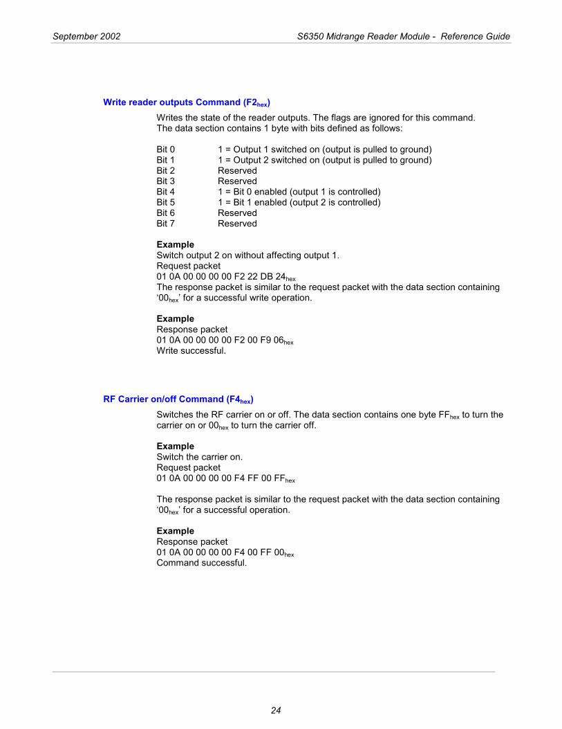
Write reader outputs Command (F2hex) Writes the state of the reader outputs. The flags are ignored for this command. The data section contains 1 byte with bits defined as follows: Bit 0 1 = Output 1 switched on (output is pulled to ground) Bit 1 1 = Output 2 switched on (output is pulled to ground) Bit 2 Reserved Bit 3 Reserved Bit 4 1 = Bit 0 enabled (output 1 is controlled) Bit 5 1 = Bit 1 enabled (output 2 is controlled) Bit 6 Reserved Bit 7 Reserved Example Switch output 2 on without affecting output 1. Request packet 01 0A 00 00 00 00 F2 22 DB 24hex The response packet is similar to the request packet with the data section containing ‘00hex’ for a successful write operation. Example Response packet 01 0A 00 00 00 00 F2 00 F9 06hex Write successful.
RF Carrier on/off Command (F4hex) Switches the RF carrier on or off. The data section contains one byte FFhex to turn the carrier on or 00hex to turn the carrier off. Example Switch the carrier on. Request packet 01 0A 00 00 00 00 F4 FF 00 FFhex The response packet is similar to the request packet with the data section containing ‘00hex’ for a successful operation. Example Response packet 01 0A 00 00 00 00 F4 00 FF 00hex Command successful.
September 2002 S6350 Midrange Reader Module - Reference Guide
25
Baud Rate Configuration Command (FF hex) This command is used to change the baud rate of the reader. Data Byte (1byte) = Baud rate code 09 = 57600 baud (default) 08 = 38400 baud 07 = 19200 baud 06 = 9600 baud Example Set Baud rate to 57600baud. Request packet 01 0A 00 00 00 00 FF 09 FD 02hex Set Baud rate to 38400baud. Request packet 01 0A 00 00 00 00 FF 08 FC 03hex Set Baud rate to 19200baud. Request packet 01 0A 00 00 00 00 FF 07 F3 0Chex Set Baud rate to 9600baud. Request packet 01 0A 00 00 00 00 FF 06 F2 0Dhex The response packet is similar to the request packet with the data section containing ‘00hex’ for a successful operation. Example Response packet 01 0A 00 00 00 00 FF 00 F4 0Bhex Command successful.
Note:
Changing this parameter only becomes effective after a power-on reset of the reader.
September 2002 S6350 Midrange Reader Module - Reference Guide
26
3.2.3 ISO/IEC 15693 Part 3 Transmission Protocol
In addition to supporting the Tag-it HF transponder protocol outlined within the preceding section, the S6350 Midrange Reader Module complies with the standard RF interface and transmission protocol of ISO/IEC 15693-2, -3. Please note that each of the ISO protocol command and response packets outlined within the following sections are contained within the standard reader protocol as outlined within Section 3.1. The ISO 15693-3 commands that are specifically applicable to the S6350 Reader are defined within the following table.
3.2.3.1 ISO/IEC 15693-3 Command Codes
Command Function Command Code
Inventory (Mandatory Command) 01hex Stay Quiet (Mandatory Command) 02hex Read Single Block 20hex Write Single Block* 21hex Lock Block* 22hex Read Multiple Blocks 23hex Write AFI* 27hex Lock AFI* 28hex Write DSFID* 29hex Lock DSFID* 2Ahex Get Multiple Block Security Status 2Chex
Note:
* Bit 7 of the ISO 15693 protocol Option_Flag must be set to 1 for all Write and Lock commands to respond properly.
September 2002 S6350 Midrange Reader Module - Reference Guide
27
3.2.3.2 Request/Response Packet Format for ISO/IEC 15693-3
The data packet from the host to the reader is known as the request and the reply from the reader to the host as the response. The host is always the primary station and initiates all communication sequences. These consist of request/response pairs where the host waits for a response before continuing. All ISO/IEC 15693-3 command request packets are contained within the standard reader command request packet format. In all cases, reader command 60hex is used to pass through ISO 15693 Part 3 commands to the reader.
Note:
The Reader’s RF Physical Layer is defined as:
Reader to Transponder: 10% - 30% (nominally set at 20%) or 100% modulation (set by software) - ASK. Data Coding Mode: 1 / 4 or 1 / 256 Transponder to Reader: FSK / Fast Data Rate.
The Configuration Byte (ISO Command Data Byte 0) As detailed in ISO/IEC 15693-2, the Configuration Byte (ISO Command Data Byte 0) is an 8-bit byte that is used to configure the Data Coding Mode and Modulation Depth of the reader.
Modulation Depth
Bit 4 of the Configuration Byte is used to set Modulation Depth. When set high the reader is configured for 100% Modulation Depth, when set low the reader will operate at 10% to 30% (with a 20% nominal setting) Modulation Depth.
Data Coding Mode
Bit 0 of the Configuration Byte is used to set the Data Coding Mode. When set high the reader is configured for Data Coding Mode 1 / 4; when set low the reader is configured for Data Coding Mode 1 / 256.
Request Packet Format for ISO/IEC 15693-3
The request packet consists of the header, packet length, node address, command flags, reader command (60hex), ISO/IEC 15693-3 command/data bytes 0 to some number “n” (where byte 0 is the configuration byte) and the checksum.
September 2002 S6350 Midrange Reader Module - Reference Guide
28
ISO 15693 Command Data Request Structure
The structure of the ISO 15693 Command Data Request is contained within the Data section of the ISO Command Data, bytes 1 - n. Specific to the S6350 Midrange Reader Module, the ISO 15693 SOF, CRC16 and EOF fields must not be included in the message data packet. Please refer to ISO/IEC 15693-3 for details about the ISO packet format. Specific to the S6350 reader, the ISO 15693 SOF, CRC16 and EOF fields must not be included.
Note:
The protocol of S6350 Midrange Reader Modue does not use the ISO 15693 SOF, CRC16 and EOF fields within its message packet.
Note:
Please refer to ISO/IEC 15693-3 for details about the ISO message packet.
Request Packet Format
Standard reader Request Packet Format (See Section 3.1)
ISO Command Data
Header Packet Length
Node Address
Command Flag
Command
Config. Byte
Data
Checksum
‘01hex’ LSB MSB LSB MSB Flags ‘60hex’ XXhex Data Byte 1 Byte 2 Byte 0 bytes
1 - n 1 byte 2 bytes 2 bytes 1 byte 1 byte
1 byte n bytes
2 bytes
Request Packet Description
Field Length Description Header 1 byte Defines the start of the packet (01hex). Packet Length 2 bytes Defines the length of the packet, including checksum. Node Address 2 bytes Defines the Node address of the reader. Command Flags 1 byte Defines how a command will be executed. Command 1 byte Defines the command for the reader to execute (60hex for
ISO 15693-3 commands) Data 0 - n
bytes Defines the data required by the reader for a command.
Checksum 2 bytes Byte 1 is an XOR checksum of all elements from the header to the last byte
September 2002 S6350 Midrange Reader Module - Reference Guide
29
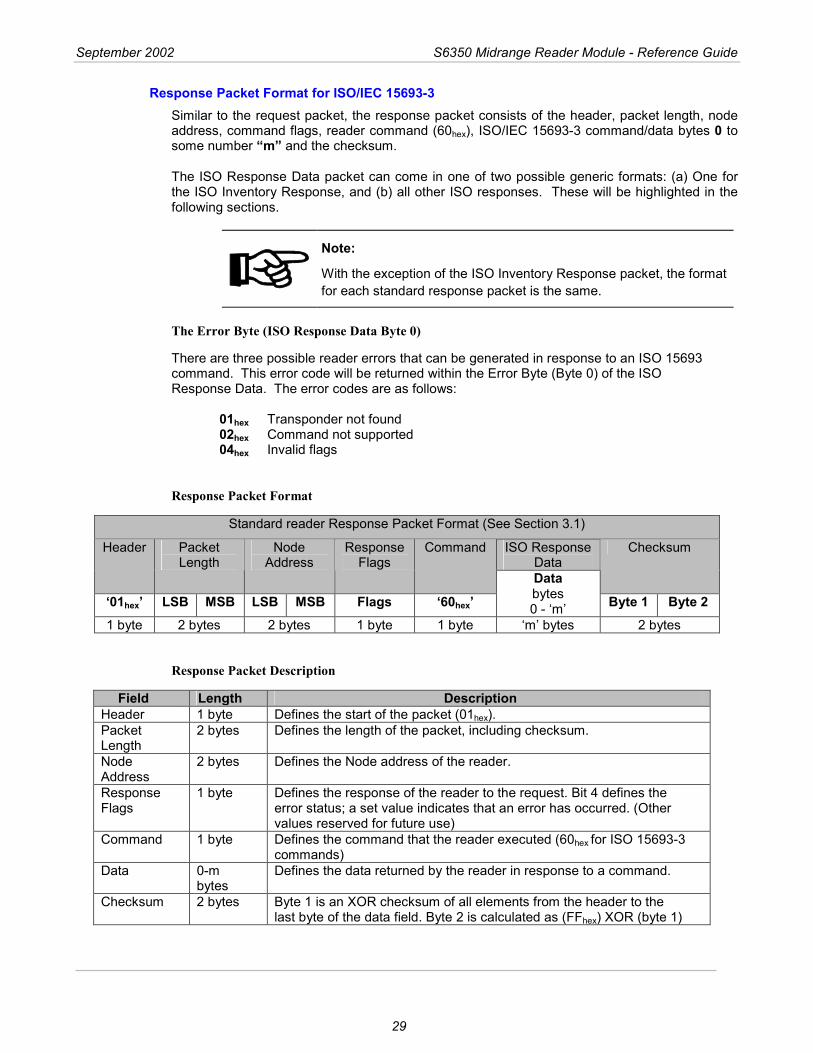
Response Packet Format for ISO/IEC 15693-3 Similar to the request packet, the response packet consists of the header, packet length, node address, command flags, reader command (60hex), ISO/IEC 15693-3 command/data bytes 0 to some number “m” and the checksum. The ISO Response Data packet can come in one of two possible generic formats: (a) One for the ISO Inventory Response, and (b) all other ISO responses. These will be highlighted in the following sections.
Note:
With the exception of the ISO Inventory Response packet, the format for each standard response packet is the same.
The Error Byte (ISO Response Data Byte 0)
There are three possible reader errors that can be generated in response to an ISO 15693 command. This error code will be returned within the Error Byte (Byte 0) of the ISO Response Data. The error codes are as follows:
01hex Transponder not found 02hex Command not supported 04hex Invalid flags
Response Packet Format
Standard reader Response Packet Format (See Section 3.1)
ISO Response Data
Header Packet Length
Node Address
Response Flags
Command Checksum
‘01hex’ LSB MSB LSB MSB Flags ‘60hex’
Data bytes 0 - ‘m’ Byte 1 Byte 2
1 byte 2 bytes 2 bytes 1 byte 1 byte ‘m’ bytes 2 bytes
Response Packet Description
Field Length Description Header 1 byte Defines the start of the packet (01hex). Packet Length
2 bytes Defines the length of the packet, including checksum.
Node Address
2 bytes Defines the Node address of the reader.
Response Flags
1 byte Defines the response of the reader to the request. Bit 4 defines the error status; a set value indicates that an error has occurred. (Other values reserved for future use)
Command 1 byte Defines the command that the reader executed (60hex for ISO 15693-3 commands)
Data 0-m bytes
Defines the data returned by the reader in response to a command.
Checksum 2 bytes Byte 1 is an XOR checksum of all elements from the header to the last byte of the data field. Byte 2 is calculated as (FFhex) XOR (byte 1)
September 2002 S6350 Midrange Reader Module - Reference Guide
30
3.2.3.3 Mandatory Commands
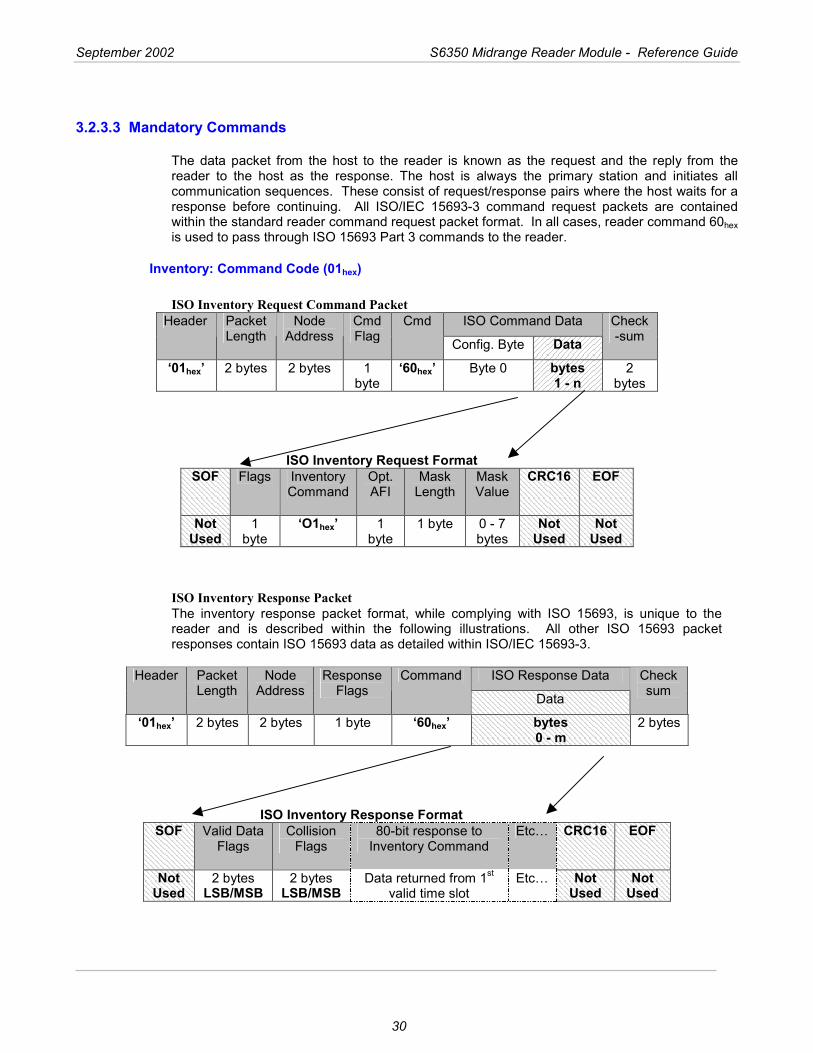
The data packet from the host to the reader is known as the request and the reply from the reader to the host as the response. The host is always the primary station and initiates all communication sequences. These consist of request/response pairs where the host waits for a response before continuing. All ISO/IEC 15693-3 command request packets are contained within the standard reader command request packet format. In all cases, reader command 60hex is used to pass through ISO 15693 Part 3 commands to the reader.
Inventory: Command Code (01hex)
ISO Inventory Request Command Packet ISO Command Data Header Packet
Length Node
Address Cmd Flag
Cmd
Config. Byte Data Check-sum
‘01hex’ 2 bytes 2 bytes 1 byte
‘60hex’ Byte 0 bytes 1 - n
2 bytes
ISO Inventory Request Format
SOF Flags Inventory Command
Opt. AFI
Mask Length
Mask Value
CRC16 EOF
Not Used
1 byte
‘O1hex’ 1 byte
1 byte 0 - 7 bytes
Not Used
Not Used
ISO Inventory Response Packet The inventory response packet format, while complying with ISO 15693, is unique to the reader and is described within the following illustrations. All other ISO 15693 packet responses contain ISO 15693 data as detailed within ISO/IEC 15693-3.
ISO Response Data Header Packet Length
Node Address
Response Flags
Command
Data
Checksum
‘01hex’ 2 bytes 2 bytes 1 byte ‘60hex’ bytes 0 - m
2 bytes
ISO Inventory Response Format
SOF Valid Data Flags
Collision Flags
80-bit response to Inventory Command
Etc… CRC16 EOF
Not Used
2 bytes LSB/MSB
2 bytes LSB/MSB
Data returned from 1st valid time slot
Etc… Not Used
Not Used
September 2002 S6350 Midrange Reader Module - Reference Guide
31
Valid Data & Collision Flags Valid Data Flags: This 16-bit field corresponds to whether valid data was received in the 16 possible Time Slots. Bits 0 to 7 of the LSB respectively correspond to Time Slots 1 to 8, while bits 0 to 7 of the MSB correspond to Time Slots 9 to 16 respectively. A set bit corresponds to valid data being received in that particular Time slot.
Collision Flags: This 16-bit field corresponding to whether a collision occurred in the 16 possible Time Slots. Bits 0 to 7 of the LSB respectively correspond to Time Slots 1 to 8, while bits 0 to 7 of the MSB correspond to Time Slots 9 to 16 respectively. A set bit corresponds to a collision being detected in that particular Time Slot.
Note:
It is possible to issue the Inventory Command for just 1 Time Slot instead of 16. In this case, the preceding packet structure is still valid; the required Valid Data flag and Collision flag reside in bit 0 of the LSB of their respective fields. It follows that issuing the Inventory Command for a single Time Slot will result in a maximum of one 80-bit response being returned
If both a Valid Data flag and its corresponding Collision flag are both clear then this indicates that no transponder was detected for that particular Time Slot.
Starting from Time Slot 1 and progressing to Time Slot 16, for each Time Slot where a transponder was successfully read (without collision), its 80-bit data is appended to the Data section of the message packet.
September 2002 S6350 Midrange Reader Module - Reference Guide
32
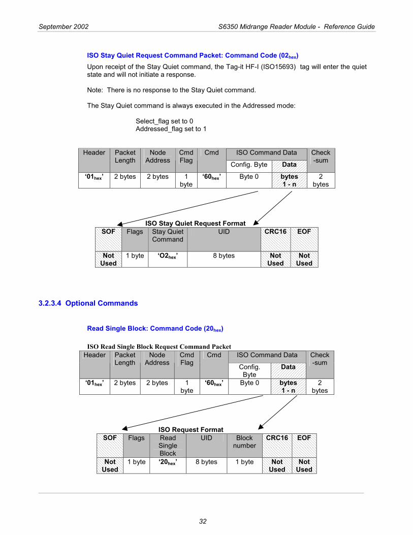
ISO Stay Quiet Request Command Packet: Command Code (02hex) Upon receipt of the Stay Quiet command, the Tag-it HF-I (ISO15693) tag will enter the quiet state and will not initiate a response. Note: There is no response to the Stay Quiet command.
The Stay Quiet command is always executed in the Addressed mode:
Select_flag set to 0 Addressed_flag set to 1
ISO Command Data Header Packet Length
Node Address
Cmd Flag
Cmd
Config. Byte Data Check-sum
‘01hex’ 2 bytes 2 bytes 1 byte
‘60hex’ Byte 0 bytes 1 - n
2 bytes
ISO Stay Quiet Request Format
SOF Flags Stay Quiet Command
UID CRC16 EOF
Not Used
1 byte ‘O2hex’ 8 bytes Not Used
Not Used
3.2.3.4 Optional Commands
Read Single Block: Command Code (20hex)
ISO Read Single Block Request Command Packet ISO Command Data Header Packet
Length Node
Address Cmd Flag
Cmd
Config. Byte
Data Check-sum
‘01hex’ 2 bytes 2 bytes 1 byte
‘60hex’ Byte 0 bytes 1 - n
2 bytes
ISO Request Format
SOF Flags Read Single Block
UID Block number
CRC16 EOF
Not Used
1 byte ‘20hex’ 8 bytes 1 byte Not Used
Not Used
September 2002 S6350 Midrange Reader Module - Reference Guide
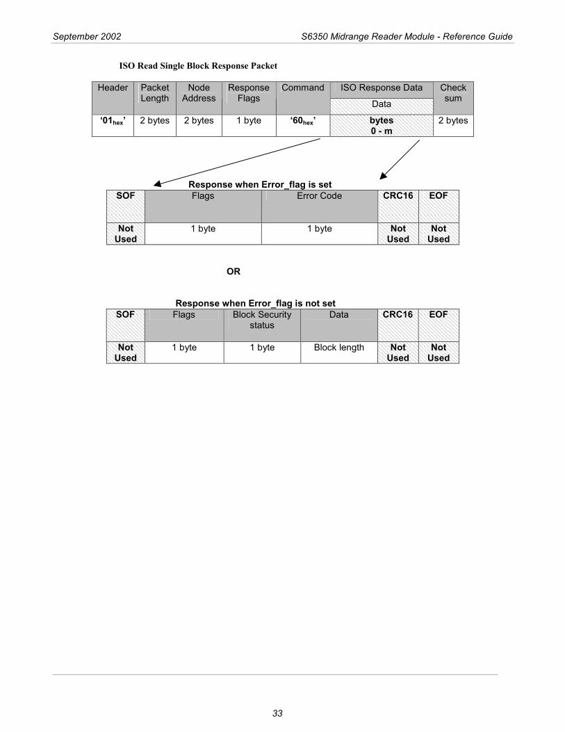
33
ISO Read Single Block Response Packet
ISO Response Data Header Packet Length
Node Address
Response Flags
Command
Data
Checksum
‘01hex’ 2 bytes 2 bytes 1 byte ‘60hex’ bytes 0 - m
2 bytes
Response when Error_flag is set
SOF Flags Error Code CRC16 EOF
Not Used
1 byte 1 byte Not Used
Not Used
OR
Response when Error_flag is not set SOF Flags Block Security
status Data CRC16 EOF
Not Used
1 byte 1 byte Block length Not Used
Not Used
September 2002 S6350 Midrange Reader Module - Reference Guide
34
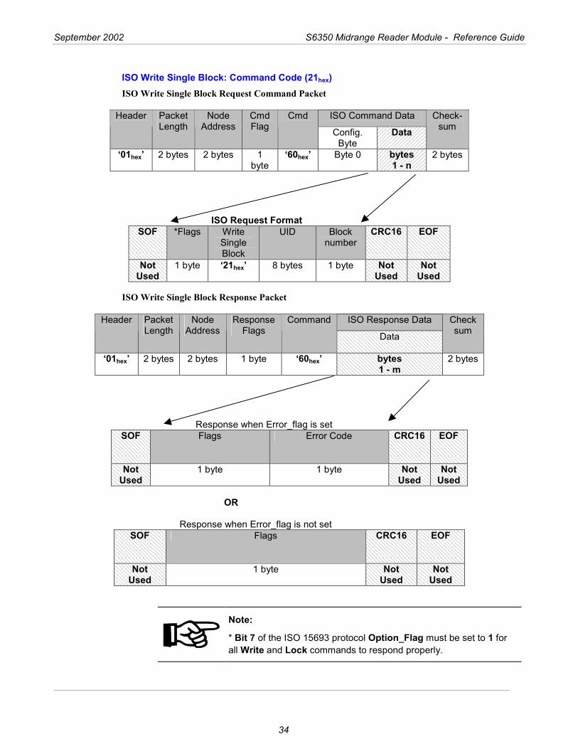
ISO Write Single Block: Command Code (21hex) ISO Write Single Block Request Command Packet
ISO Command Data Header Packet
Length Node
Address Cmd Flag
Cmd
Config. Byte
Data Check-
sum
‘01hex’ 2 bytes 2 bytes 1 byte
‘60hex’ Byte 0 bytes 1 - n
2 bytes
ISO Request Format
SOF *Flags Write Single Block
UID Block number
CRC16 EOF
Not Used
1 byte ‘21hex’ 8 bytes 1 byte Not Used
Not Used
ISO Write Single Block Response Packet
ISO Response Data Header Packet Length
Node Address
Response Flags
Command
Data
Checksum
‘01hex’ 2 bytes 2 bytes 1 byte ‘60hex’ bytes 1 - m
2 bytes
Response when Error_flag is set
SOF Flags Error Code CRC16 EOF
Not Used
1 byte 1 byte Not Used
Not Used
OR
Response when Error_flag is not set SOF Flags CRC16 EOF
Not Used
1 byte Not Used
Not Used
Note:
* Bit 7 of the ISO 15693 protocol Option_Flag must be set to 1 for all Write and Lock commands to respond properly.
September 2002 S6350 Midrange Reader Module - Reference Guide
35
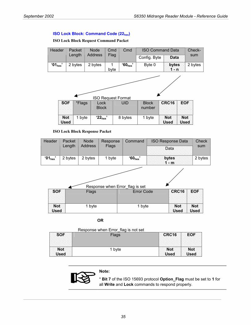
ISO Lock Block: Command Code (22hex) ISO Lock Block Request Command Packet
ISO Command Data Header Packet
Length Node
Address Cmd Flag
Cmd
Config. Byte Data Check-
sum
‘01hex’ 2 bytes 2 bytes 1 byte
‘60hex’ Byte 0 bytes 1 - n
2 bytes
ISO Request Format
SOF *Flags Lock Block
UID Block number
CRC16 EOF
Not Used
1 byte ‘22hex’ 8 bytes 1 byte Not Used
Not Used
ISO Lock Block Response Packet
ISO Response Data Header Packet Length
Node Address
Response Flags
Command
Data
Checksum
‘01hex’ 2 bytes 2 bytes 1 byte ‘60hex’ bytes 1 - m
2 bytes
Response when Error_flag is set
SOF Flags Error Code CRC16 EOF
Not Used
1 byte 1 byte Not Used
Not Used
OR
Response when Error_flag is not set SOF Flags CRC16 EOF
Not Used
1 byte Not Used
Not Used
Note:
* Bit 7 of the ISO 15693 protocol Option_Flag must be set to 1 for all Write and Lock commands to respond properly.
September 2002 S6350 Midrange Reader Module - Reference Guide
36
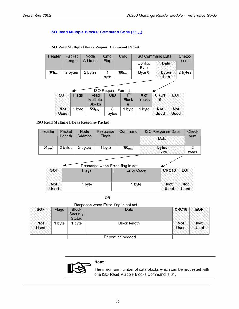
ISO Read Multiple Blocks: Command Code (23hex)
ISO Read Multiple Blocks Request Command Packet
ISO Command Data Header Packet
Length Node
Address Cmd Flag
Cmd
Config. Byte
Data Check-
sum
‘01hex’ 2 bytes 2 bytes 1 byte
‘60hex’ Byte 0 bytes 1 - n
2 bytes
ISO Request Format
SOF Flags Read Multiple Blocks
UID 1st Block
#
# of blocks
CRC16
EOF
Not Used
1 byte ‘23hex’ 8 bytes
1 byte 1 byte Not Used
Not Used
ISO Read Multiple Blocks Response Packet
ISO Response Data Header Packet Length
Node Address
Response Flags
Command
Data
Checksum
‘01hex’ 2 bytes 2 bytes 1 byte ‘60hex’ bytes 1 - m
2 bytes
Response when Error_flag is set
SOF Flags Error Code CRC16 EOF
Not Used
1 byte 1 byte Not Used
Not Used
OR
Response when Error_flag is not set SOF Flags Block
Security Status
Data CRC16 EOF
Not Used
1 byte 1 byte Block length Not Used
Not Used
Repeat as needed
Note:
The maximum number of data blocks which can be requested with one ISO Read Multiple Blocks Command is 61.

September 2002 S6350 Midrange Reader Module - Reference Guide
37
ISO Write AFI: Command Code (27hex) ISO Write AFI Request Command Packet
ISO Command Data Header Packet
Length Node
Address Cmd Flag
Cmd
Config. Byte Data Check-sum
‘01hex’ 2 bytes 2 bytes 1 byte
‘60hex’ Byte 0 bytes 1 - n
2 bytes
ISO Request Format
SOF *Flags Write AFI
UID AFI CRC16 EOF
Not Used
1 byte ‘27hex’ 8 bytes 1 byte Not Used
Not Used
ISO Write AFI Response Packet
ISO Response Data Header Packet Length
Node Address
Response Flags
Command
Data
Checksum
‘01hex’ 2 bytes 2 bytes 1 byte ‘60hex’ bytes 1 - m
2 bytes
Response when Error_flag is set
SOF Flags Error Code CRC16 EOF
Not Used
1 byte 1 byte Not Used
Not Used
OR
Response when Error_flag is not set SOF Flags CRC16 EOF
Not Used
1 byte Not Used
Not Used
Note:
* Bit 7 of the ISO 15693 protocol Option_Flag must be set to 1 for all Write and Lock commands to respond properly.
September 2002 S6350 Midrange Reader Module - Reference Guide
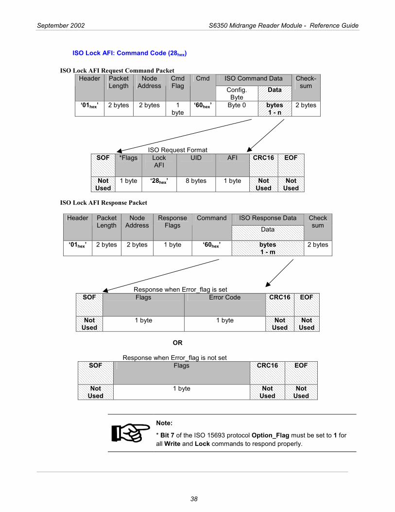
38
ISO Lock AFI: Command Code (28hex)
ISO Lock AFI Request Command Packet ISO Command Data Header Packet
Length Node
Address Cmd Flag
Cmd
Config. Byte
Data Check-
sum
‘01hex’ 2 bytes 2 bytes 1 byte
‘60hex’ Byte 0 bytes 1 - n
2 bytes
ISO Request Format
SOF *Flags Lock AFI
UID AFI CRC16 EOF
Not Used
1 byte ‘28hex’ 8 bytes 1 byte Not Used
Not Used
ISO Lock AFI Response Packet
ISO Response Data Header Packet Length
Node Address
Response Flags
Command
Data
Checksum
‘01hex’ 2 bytes 2 bytes 1 byte ‘60hex’ bytes 1 - m
2 bytes
Response when Error_flag is set
SOF Flags Error Code CRC16 EOF
Not Used
1 byte 1 byte Not Used
Not Used
OR
Response when Error_flag is not set SOF Flags CRC16 EOF
Not Used
1 byte Not Used
Not Used
Note:
* Bit 7 of the ISO 15693 protocol Option_Flag must be set to 1 for all Write and Lock commands to respond properly.
September 2002 S6350 Midrange Reader Module - Reference Guide
39
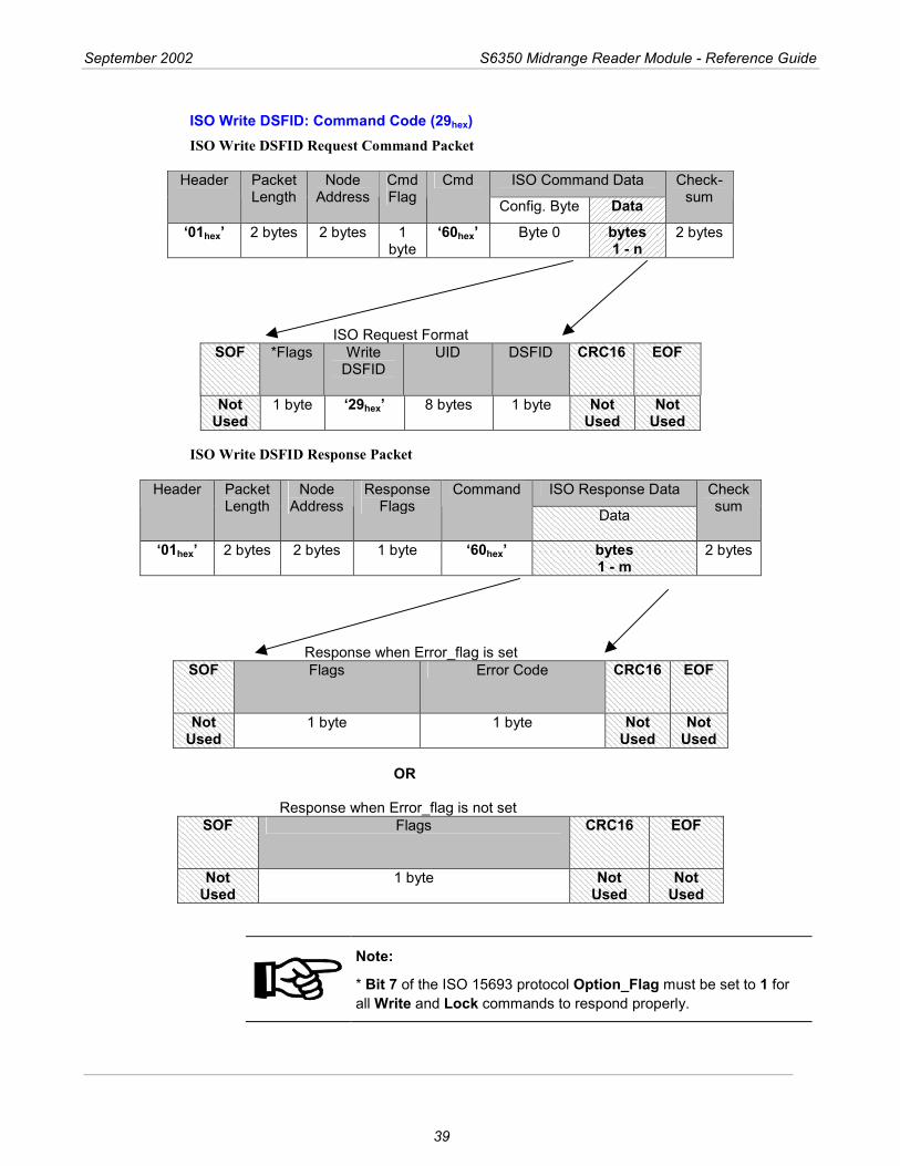
ISO Write DSFID: Command Code (29hex) ISO Write DSFID Request Command Packet
ISO Command Data Header Packet Length
Node Address
Cmd Flag
Cmd
Config. Byte Data Check-
sum
‘01hex’ 2 bytes 2 bytes 1 byte
‘60hex’ Byte 0 bytes 1 - n
2 bytes
ISO Request Format
SOF *Flags Write DSFID
UID DSFID CRC16 EOF
Not Used
1 byte ‘29hex’ 8 bytes 1 byte Not Used
Not Used
ISO Write DSFID Response Packet
ISO Response Data Header Packet Length
Node Address
Response Flags
Command
Data
Checksum
‘01hex’ 2 bytes 2 bytes 1 byte ‘60hex’ bytes 1 - m
2 bytes
Response when Error_flag is set
SOF Flags Error Code CRC16 EOF
Not Used
1 byte 1 byte Not Used
Not Used
OR
Response when Error_flag is not set SOF Flags CRC16 EOF
Not Used
1 byte Not Used
Not Used
Note:
* Bit 7 of the ISO 15693 protocol Option_Flag must be set to 1 for all Write and Lock commands to respond properly.
September 2002 S6350 Midrange Reader Module - Reference Guide
40
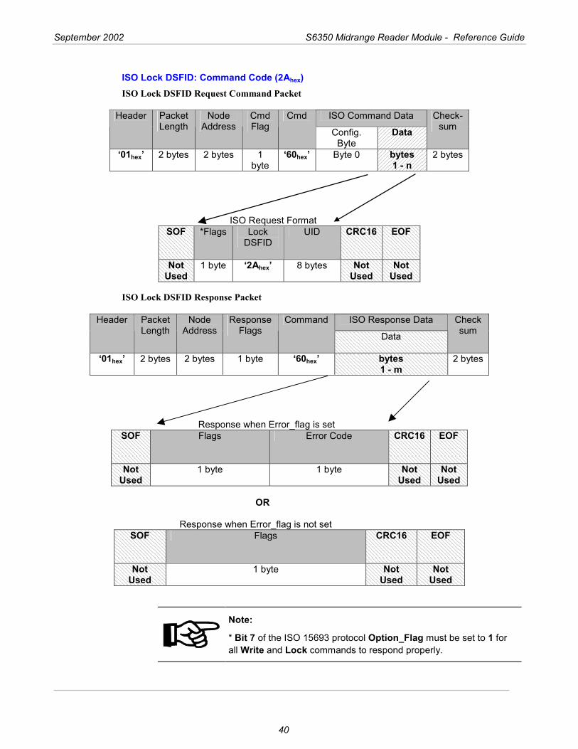
ISO Lock DSFID: Command Code (2Ahex) ISO Lock DSFID Request Command Packet
ISO Command Data Header Packet
Length Node
Address Cmd Flag
Cmd
Config. Byte
Data Check-
sum
‘01hex’ 2 bytes 2 bytes 1 byte
‘60hex’ Byte 0 bytes 1 - n
2 bytes
ISO Request Format
SOF *Flags Lock DSFID
UID CRC16 EOF
Not Used
1 byte ‘2Ahex’ 8 bytes Not Used
Not Used
ISO Lock DSFID Response Packet
ISO Response Data Header Packet Length
Node Address
Response Flags
Command
Data
Checksum
‘01hex’ 2 bytes 2 bytes 1 byte ‘60hex’ bytes 1 - m
2 bytes
Response when Error_flag is set
SOF Flags Error Code CRC16 EOF
Not Used
1 byte 1 byte Not Used
Not Used
OR
Response when Error_flag is not set SOF Flags CRC16 EOF
Not Used
1 byte Not Used
Not Used
Note:
* Bit 7 of the ISO 15693 protocol Option_Flag must be set to 1 for all Write and Lock commands to respond properly.
September 2002 S6350 Midrange Reader Module - Reference Guide
41
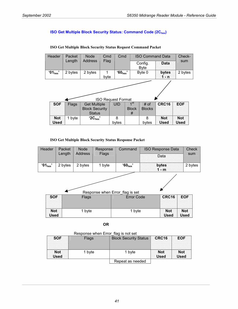
ISO Get Multiple Block Security Status: Command Code (2Chex)
ISO Get Multiple Block Security Status Request Command Packet
ISO Command Data Header Packet
Length Node
Address Cmd Flag
Cmd
Config. Byte
Data Check-
sum
‘01hex’ 2 bytes 2 bytes 1 byte
‘60hex’ Byte 0 bytes 1 - n
2 bytes
ISO Request Format
SOF Flags Get Multiple Block Security
Status
UID 1st Block
#
# of Blocks
CRC16 EOF
Not Used
1 byte ‘2Chex’ 8 bytes
8 bytes
Not Used
Not Used
ISO Get Multiple Block Security Status Response Packet
ISO Response Data Header Packet Length
Node Address
Response Flags
Command
Data
Checksum
‘01hex’ 2 bytes 2 bytes 1 byte ‘60hex’ bytes 1 - m
2 bytes
Response when Error_flag is set
SOF Flags Error Code CRC16 EOF
Not Used
1 byte 1 byte Not Used
Not Used
OR
Response when Error_flag is not set SOF Flags Block Security Status CRC16 EOF
Not Used
1 byte 1 byte Not Used
Not Used
Repeat as needed
42
Regulatory and Warranty Notices
Topic Page 4.1 Regulatory Notes ............................................................................................. 43 4.2 FCC Notices (U.S.A.)....................................................................................... 43 4.3 R&TTE Conformity (Europe)........................................................................... 43 4.4 Warranty and Liability ...................................................................................... 43
Chapter 4
September 2002 Series 6350 Reader Reference Guide
43
4.1 Regulatory Notes
An RFID system comprises an RF transmission device, and is therefore subject to national and international regulations. Prior to operating the S6350 Midrange Reader Module together with antenna and power supply, the required FCC, PTT or relevant government agency approval must be obtained. Sales, lease or operation in some countries may be subject to prior approval by the government or other organization.
4.2 FCC Notices (U.S.A.)
A typical system configuration containing the S6350 Midrange Reader Module has been tested and found to comply with the limits for a Class A digital device, pursuant to Part 15 of the FCC Rules. It is the responsibility of the system integrators to get their complete system tested and to obtain approvals from the appropriate local authorities before operating or selling this system.
4.3 R&TTE Conformity (Europe)
A typical system configuration containing the S6350 Midrange Reader Module has been tested and found to comply with the requirements of the Telecommunication Terminal Equipment Act (FTEG) and the R&TTE Directive 1999/5/EC. Any device or system incorporating the S6350 Midrange Reader Module in any other than the originally tested configuration needs to be verified against the requirements of the Telecommunication Terminal Equipment Act (FTEG) and the R&TTE Directive 1999/5/EC. A separate Declaration of Conformity must be issued by the System Integrator or user of such a system prior to marketing and operating it in European Community.
It is the responsibility of the system integrator to get their complete system tested and obtain approvals from the appropriate local authorities before operating or selling the system.
4.4 Warranty and Liability
The "General Conditions of Sale and Delivery" of Texas Instruments Incorporated or a TI subsidiary apply. Warranty and liability claims for defect products, injuries to persons and property damages are void if they are the result of one or more of the following causes:
Improper use of the reader module. Unauthorized assembly, operation and maintenance of the reader module. Operation of the reader modules with defective and/or non-functioning safety and
protective equipment. Failure to observe the instructions during transport, storage, assembly, operation,
maintenance and setting up of the reader modules. Unauthorized changes to the reader modules. Insufficient monitoring of the reader modules' operation or environmental conditions. Improperly conducted repairs. Catastrophes caused by foreign bodies and acts of God.
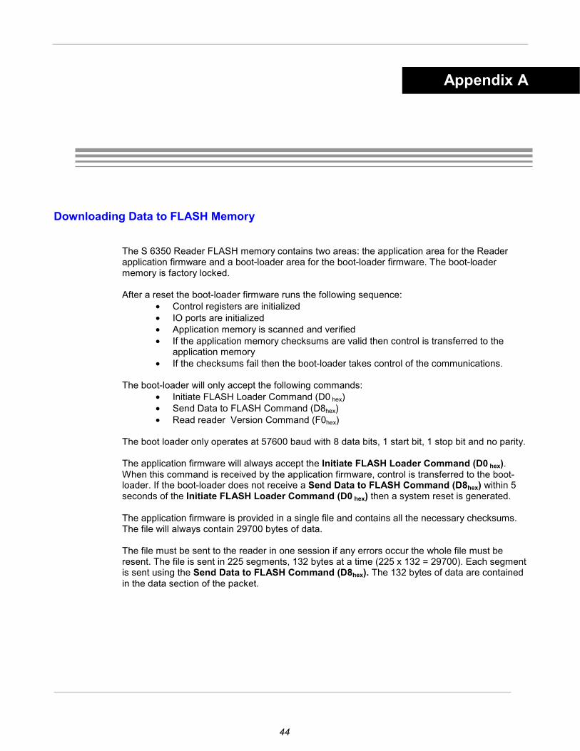
44
Downloading Data to FLASH Memory
The S 6350 Reader FLASH memory contains two areas: the application area for the Reader application firmware and a boot-loader area for the boot-loader firmware. The boot-loader memory is factory locked. After a reset the boot-loader firmware runs the following sequence:
• Control registers are initialized • IO ports are initialized • Application memory is scanned and verified • If the application memory checksums are valid then control is transferred to the
application memory • If the checksums fail then the boot-loader takes control of the communications.
The boot-loader will only accept the following commands: • Initiate FLASH Loader Command (D0 hex) • Send Data to FLASH Command (D8hex) • Read reader Version Command (F0hex)
The boot loader only operates at 57600 baud with 8 data bits, 1 start bit, 1 stop bit and no parity. The application firmware will always accept the Initiate FLASH Loader Command (D0 hex). When this command is received by the application firmware, control is transferred to the boot-loader. If the boot-loader does not receive a Send Data to FLASH Command (D8hex) within 5 seconds of the Initiate FLASH Loader Command (D0 hex) then a system reset is generated. The application firmware is provided in a single file and contains all the necessary checksums. The file will always contain 29700 bytes of data. The file must be sent to the reader in one session if any errors occur the whole file must be resent. The file is sent in 225 segments, 132 bytes at a time (225 x 132 = 29700). Each segment is sent using the Send Data to FLASH Command (D8hex). The 132 bytes of data are contained in the data section of the packet.
Appendix A
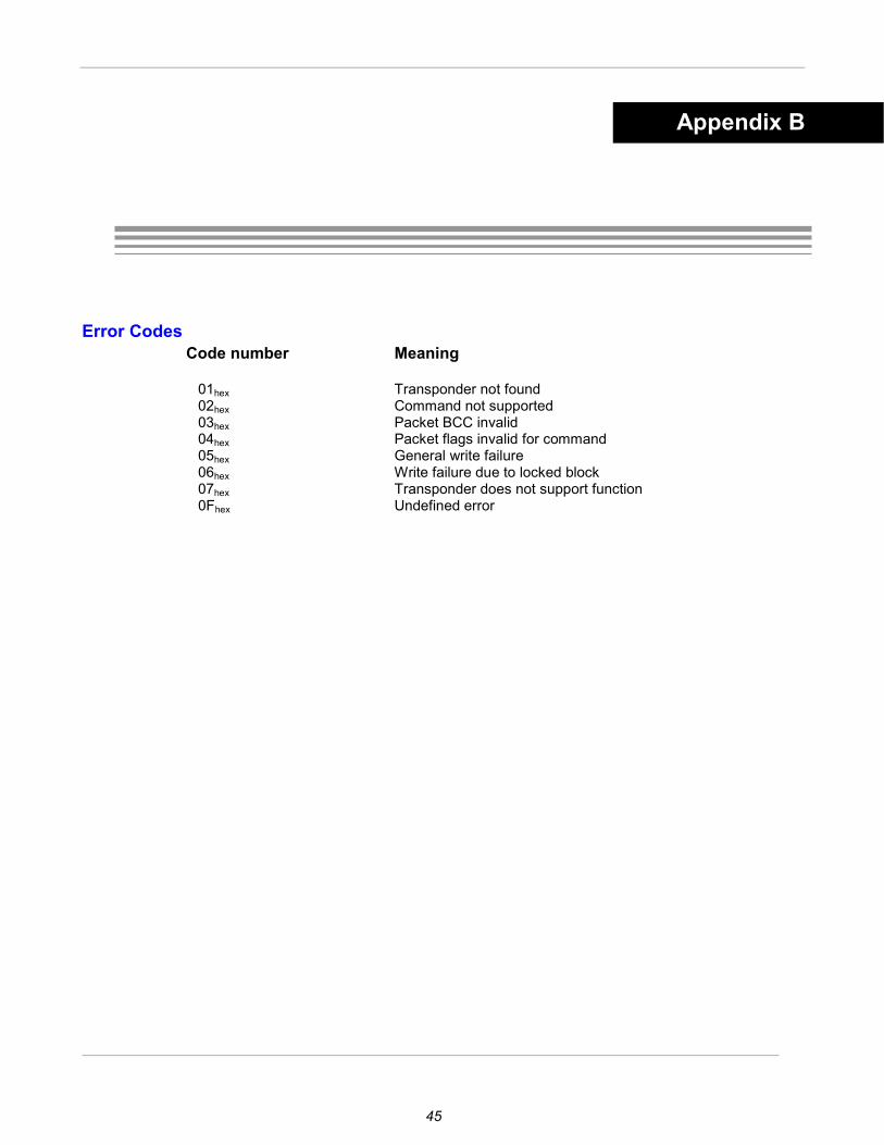
45
Error Codes Code number Meaning 01hex Transponder not found 02hex Command not supported 03hex Packet BCC invalid 04hex Packet flags invalid for command 05hex General write failure 06hex Write failure due to locked block 07hex Transponder does not support function 0Fhex Undefined error
Appendix B
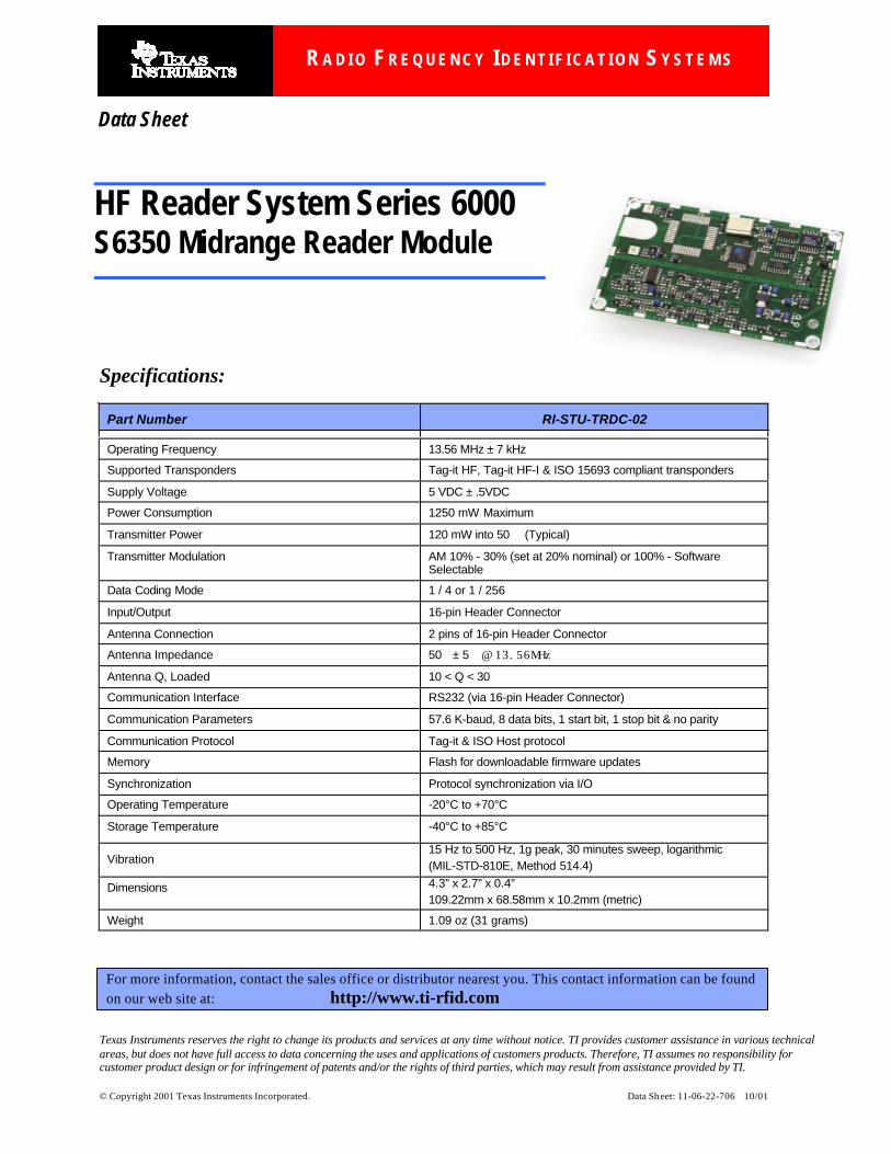
Texas Instruments reserves the right to change its products and services at any time without notice. TI provides customer assistance in various technicalareas, but does not have full access to data concerning the uses and applications of customers products. Therefore, TI assumes no responsibility forcustomer product design or for infringement of patents and/or the rights of third parties, which may result from assistance provided by TI.
© Copyright 2001 Texas Instruments Incorporated. Data Sheet: 11-06-22-706 10/01
Specifications:
Part Number RI-STU-TRDC-02
Operating Frequency 13.56 MHz ± 7 kHz
Supported Transponders Tag-it HF, Tag-it HF-I & ISO 15693 compliant transponders
Supply Voltage 5 VDC ± .5VDC
Power Consumption 1250 mW Maximum
Transmitter Power 120 mW into 50 (Typical)
Transmitter Modulation AM 10% - 30% (set at 20% nominal) or 100% - SoftwareSelectable
Data Coding Mode 1 / 4 or 1 / 256
Input/Output 16-pin Header Connector
Antenna Connection 2 pins of 16-pin Header Connector
Antenna Impedance 50 ± 5 @ 13.56MHz
Antenna Q, Loaded 10 < Q < 30
Communication Interface RS232 (via 16-pin Header Connector)
Communication Parameters 57.6 K-baud, 8 data bits, 1 start bit, 1 stop bit & no parity
Communication Protocol Tag-it & ISO Host protocol
Memory Flash for downloadable firmware updates
Synchronization Protocol synchronization via I/O
Operating Temperature -20°C to +70°C
Storage Temperature -40°C to +85°C
Vibration15 Hz to 500 Hz, 1g peak, 30 minutes sweep, logarithmic(MIL-STD-810E, Method 514.4)
Dimensions 4.3” x 2.7” x 0.4”109.22mm x 68.58mm x 10.2mm (metric)
Weight 1.09 oz (31 grams)
For more information, contact the sales office or distributor nearest you. This contact information can be found on our web site at: http://www.ti-rfid.com
Data Sheet
HF Reader System Series 6000S6350 Midrange Reader Module
R A D I O F R E Q U E N C Y I D E N T I F I C A T I O N S Y S T E M S