Embed Size (px)
Citation preview

It is of vital importance, before attempting to operate your engine, to read the general 'SAFETY INSTRUCTIONS AND WARNINGS' section on pages 2-5 of this booklet and to strictly adhere to the advice contained therein.
Also, please study the entire contents of this instruction manual, so as to familiarize yourself with the controls and other features of the engine.
Keep these instructions in a safe place so that you may readily refer to them whenever necessary.
It is suggested that any instructions supplied with the vehicle, radio control equipment, etc., are accessible for checking at the same time.
●
●
●
IF THE ENGINE FAILS TO START
FINAL ADJUSTMENT
CARBURETTOR CLEANLINESS
CARE AND MAINTENANCE
EXPLODED VIEW &ENGINE PARTS LIST
CARBURETOR EXPLODED VIEW & PARTS LIST
O.S. GENUINE PARTS & ACCESSORIES
THREE VIEW DRAWING
CONTENTS
SAFETY INSTRUCTIONS AND WARNINGS ABOUT YOUR O.S. ENGINE
INTRODUCTION, BASIC ENGINE PARTS
INSTALLATION
AIR CLEANER TYPE102
NOTES CONCERNING THE RECOIL STARTER
GLOWPLUG
TOOLS, ACCESSORIES, etc.
CARBURETTOR CONTROLS
PRESSURIZED FUEL SYSTEM
STARTING THE ENGINE &RUNNING-IN('Breaking-in)
2~5
6
7~8
8~9
9~10
10~11
11~12
14~15
27
16
16~17
17~18
19
20~23
24~25
2612~13
13
1
Remember that your engine is not a "toy", but a highly efficient internal-combustion machine whose power is capable of harming you, or others, if it is misused.As owner, you, alone, are responsible for the safe operation of your engine, so act with discretion and care at all times.If at some future date, your O.S. engine is acquired by another person, we would respectfully request that these instructions are also passed on to its new owner.
SAFETY INSTRUCTIONS AND WARNINGS ABOUT YOUR O.S. ENGINE
The advice which follows applies basically to ALL MODEL ENGINES and is grouped under two headings according to the degree of damage or danger which might arise through misuse or neglect.
WARNINGS NOTES
These cover events which might involve serious (in extreme circumstances, even fatal) injury.
These cover the many other possibilities, generally less obvious sources of danger, but which, under certain circumstances, may also cause damage or injury.
2
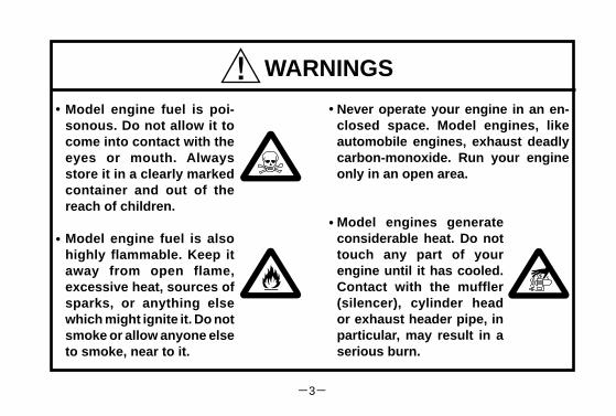
WARNINGS
Model engine fuel is poi-sonous. Do not allow it to come into contact with the eyes or mouth. Always store it in a clearly marked container and out of the reach of children.
Model engine fuel is also highly flammable. Keep it away from open flame, excessive heat, sources of sparks, or anything else which might ignite it. Do not smoke or allow anyone else to smoke, near to it.
Never operate your engine in an en-closed space. Model engines, like automobile engines, exhaust deadly carbon-monoxide. Run your engine only in an open area.
Model engines generate considerable heat. Do not touch any part of your engine until it has cooled. Contact with the muffler (silencer), cylinder head or exhaust header pipe, in particular, may result in a serious burn.
• •
••
3

This engine is intended for model cars. Do not attempt to use it for any other purpose.
Mount the engine in your model securely, following the manufacturers' recommendations, using appropriate screws and locknuts.
Fit an effective silencer (muffler). Frequent close exposure to a noisy exhaust (especially in the case of the most powerful highspeed engines) may eventually impair your hearing and such noise is also likely to cause annoyance to others over a wide area.
The wearing of safety glasses is also strongly recommended.
Take care that the glowplug clip or battery leads do not come into contact with rotating parts. Also check that the linkage to the throttle arm is secure.
For their safety, keep all onlookers (especially small children) well back (at least 20 feet or 6 meters) when preparing your model for running.
NOTES
•
•
•
•
•
•
4

NOTES
To stop the engine, fully retard the throttle stick and trim lever on the trans-mitter, or, in an emergency, cut off the fuel supply by pinching the fuel delivery tube from the tank.
•
Warning! Immediately after a glowplug-ignition engine has been run and is still warm, conditions sometimes exist whereby it is just possible for the engine to abruptly restart if it is rotated over compression WITHOUT the glowplug battery being reconnected.
•
Do not attempt to disassemble the recoil starter of the 15CV-X. If you do so, the very strong spring inside will be suddenly ejected. This can be very dangerous.
Do not extend the starter cord more than 45cm (18"). Do not abruptly release the operating handle. Allow the cord to rewind smoothly while still holding the handle.
•
•
Pull the operating handle straight out when starting the engine, so that the cord does not rub against the vehicle body or engine. This will help prevent the cord from being damaged by abrasion or engine heat.
•
5
INSTALLING THE GLOWPLUG
Carburetor
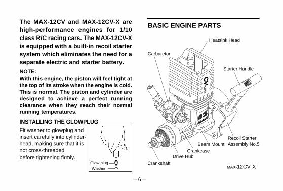
NOTE:With this engine, the piston will feel tight at the top of its stroke when the engine is cold. This is normal. The piston and cylinder are designed to achieve a perfect running clearance when they reach their normal running temperatures.
Fit washer to glowplug and insert carefully into cylinder-head, making sure that it is not cross-threadedbefore tightening firmly.
BASIC ENGINE PARTSThe MAX-12CV and MAX-12CV-X are high-performance engines for 1/10 class R/C racing cars. The MAX-12CV-X is equipped with a built-in recoil starter system which eliminates the need for a separate electric and starter battery.
CrankshaftGlow plugWasher
Drive HubCrankcase
Beam Mount
Starter Handle
Heatsink Head
Recoil StarterAssembly No.5
MAX-12CV-X
6
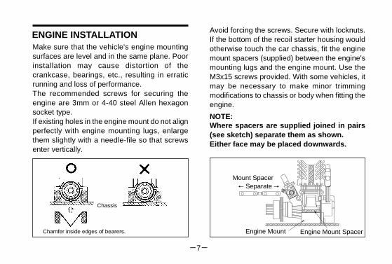
ENGINE INSTALLATIONMake sure that the vehicle's engine mounting surfaces are level and in the same plane. Poor installation may cause distortion of the crankcase, bearings, etc., resulting in erratic running and loss of performance. The recommended screws for securing the engine are 3mm or 4-40 steel Allen hexagon socket type. If existing holes in the engine mount do not align perfectly with engine mounting lugs, enlarge them slightly with a needle-file so that screws enter vertically.
Chassis
Chamfer inside edges of bearers.
NOTE:Where spacers are supplied joined in pairs (see sketch) separate them as shown. Either face may be placed downwards.
Avoid forcing the screws. Secure with locknuts. If the bottom of the recoil starter housing would otherwise touch the car chassis, fit the engine mount spacers (supplied) between the engine's mounting lugs and the engine mount. Use the M3x15 screws provided. With some vehicles, it may be necessary to make minor trimming modifications to chassis or body when fitting the engine.
Mount Spacer
Engine Mount Spacer
Separate
Engine Mount
7

ー8ー�
This is a heavy-duty wet type air cleaner that has been developed specifically for the O.S. MAX-CV series model car engines. It contains specially impregnated filter elements which prevent highly damaging dust and dirt from being drawn into the engine through the carburetor, yet allow engine performance to be maintained for longer periods between element renewals. The Type 102 air cleaner has a special rubber body which facilitates easy yet secure fitting, with positive sealing at the carburetor air intake.
AIR CLEANER TYPE 102
INSTALLATION OF AIR CLEANERCarefully clean the carburetor,removing any old adhesive or sealant that may have been previously used on the outside of the air intake.
•
Press the air cleaner body firmly over the carburetor air intake. Make sure that the outer rim of the air intake engages the internal annular groove in the air cleaner: failure to do so may result in the air cleaner falling off. See sketch, right.
•
INSTALLATION OF THE CARBURETORAs delivered, the engine has its carburetor lightly fit into the intake boss. Secure it as follows.
Loosen the retainer screw, rotate the carburetor to its correct position and make sure that it is pressed well down into the intake boss, compressing the rubber gasket, before retightening screw.
Rotate the retainer screw gently until it stops, then tighten a further 60-90˚.Do not overtighten the screw as this will damage the carburetor body.
1.
2.
Rotate the retainer nutgently until it stops.
Tighten a further 60-90˚
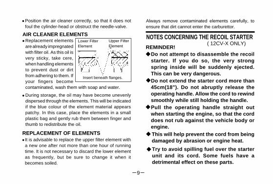
Always remove contaminated elements carefully, to ensure that dirt cannot enter the carburettor.
Position the air cleaner correctly, so that it does not foul the cylinder-head or obstruct the needle-valve.
•
AIR CLEANER ELEMENTS•
•
Lower Filter Element
Upper Filter Element
Insert beneath flanges.
Replacement elements are already impregnated with filter oil. As this oil is very sticky, take cere, when handling elements to prevent dust or dirt from adhering to them. If your fingers become contaminated, wash them with soap and water.
During storage, the oil may have become unevenly dispersed through the elements. This will be indicated if the blue colour of the element material appears patchy. In this case, place the elements in a small plastic bag and gently rub them between finger and thumb to redistribute the oil.
REPLACEMENT OF ELEMENTSIt is advisable to replace the upper filter element with a new one after not more than one hour of running time. It is not necessary to discard the lower element as frequently, but be sure to change it when it becomes soiled.
•
◆
◆
◆
NOTES CONCERNING THE RECOIL STARTER( 12CV-X ONLY)
REMINDER!◆
◆
Do not attempt to disassemble the recoil starter. If you do so, the very strong spring inside will be suddenly ejected. This can be very dangerous. Do not extend the starter cord more than 45cm(18"). Do not abruptly release the operating handle. Allow the cord to rewind smoothly while still holding the handle.Pull the operating handle straight out when starting the engine, so that the cord does not rub against the vehicle body or engine. This will help prevent the cord from being damaged by abrasion or engine heat.
Try to avoid spilling fuel over the starter unit and its cord. Some fuels have a detrimental effect on these parts.
9
Glowplug lifeParticularly in the case of very high performance engines, glowplugs must be regarded as expendable
Install a plug suitable for the engine.
Use fuel containing a moderate percentage of nitromethane unless more is essential for racing events.
Do not run the engine too lean and do not leave the battery connected while adjusting the needle.
However, plug life can be extended and engine performance maintained by careful use, i.e.:
••
•
GLOWPLUG
The role of the glowplugWith a glowplug engine, ignition is initiated by the application of a 1.5-volt power source. When the battery is disconnected, the heat retained within the combustion chamber remains sufficient to keep the plug filament glowing, thereby continuing to keep the engine running. Ignition timing is 'automatic' : under reduced load, allowing higher rpm, the plug becomes hotter and, appropriately, fires the fuel/air charge earlier; conversely, at reduced rpm, the plug become cooler and ignition is retarded.
Since the compatibility of glowplug and fuel may have a marked effect on performance and reliability, it may be worthwhile to choose the R/C type plug found most suitable after tests.Recommended O.S. plugs are A3, A5 and No8. Carefully fit plug finger-tight, before final tightening with the correct size plug wrench.
The starter prevents the engine from being rotated in the wrong direction.The unit will be damaged if you attempt to force the flywheel in the opposite direction (i.e. clockwise when viewed from the crankshaft
NOTE: Because, in the interests of personal safety, dismantling of the starter mechanism is strongly discouraged, the Recoil Starter is available for replacement only as a pre-assembled unit. However, some related parts, such as Starting Shaft and Rear Adaptor, are obtainable separately. (See Parts List.)
◆
10
Apart from when actually burned out, a plug may need to be replaced because it no longer delivers its best performance, such as when:
When to replace the glowplug
Filament surface has roughened and turned white. Filament coil has become distorted.Foreign matter has adhered to filament or plug body has corroded.Engine tends to cut out when idling.Starting qualities deteriorate.
•••
••TOOLS, ACCESSORIES, etc.The following items are necessary for operating the engine.
FUELUse only top quality methanol-based model engine fuel.For consistent performance and long engine life, it is advisable to use fuel containing AT LEAST 18% lubricant. This engine is designed to run on both low and high nitromethane content fuels,i.e. from mild mixtures containing a few percent of nitromethane, up to high-speed racing fuels containing 40% nitromethane. Generally, power output is increased-up to a certain point-as the nitromethane content of the fuelis increased.
As a starting point, we recommend a fuel containing 10-20% nitromethane, changing to a fuel containing more nitro only if necessary. When the nitro content of the fuel is increased or the brand of fuel is changed, it is advisable to initially run the engine with a richer needle-valve setting, so that the optimum setting for the new fuel may be rechecked as described in the RUNNING-IN paragraphs. When engines are run at very high speeds and on high-nitro fuels, glowplug elements do not last so long.
Model engine fuel is poisonous. Do not allow it to come into contact with the eyes or mouth. Always store it in a clearly marked container and out of the reach of children.
Model engine fuel is also highly flammable. Keep it away from open flame, excessive heat, sources of sparks, or anything else which might ignite it.
Reminder!
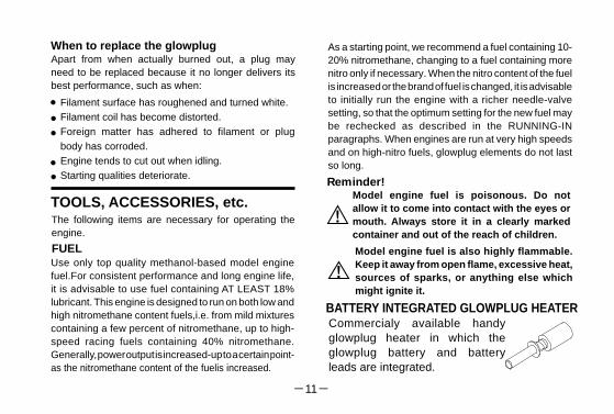
BATTERY INTEGRATED GLOWPLUG HEATERCommercialy available handy glowplug heater in which the glowplug battery and battery leads are integrated.
11

LONG SOCKET WRENCH
SILICONE TUBINGHeatproof silicone tube of approx. 5mm o.d. and 2mm i.d. is required for the connection between the fuel tank and engine.
FUEL BOTTLE OR PUMP
ELECTRIC STARTER AND STARTER BATTERYUse an electric starter with 12-volt battery for starting the MAX-12CV.
CARBURETOR CONTROLS (10C)
The Needle-Valve:
The Mixture Control Screw:
The Throttle Stop Screw:For setting the minimum idling speed.
Needle Valve
Mixture Control ValveAssembly Screw
Throttle Stop Screw
Ball LinkNOTE:Readjustment may be necessary, occa-sionally to allow for changes in fuel for-mulae, gear ratio or clutch engagement point.
Three adjustable controls are provided on this carburetor.
For adjusting the mixture strength when the throttle is fully open.
For adjusting the mixture strength at part-throttle and idling speeds, to obtain steady idling and smooth acceleration to mid speeds.
Recommended for easy removal and replacement of the angled and recessed glowplug, the O.S.Long Socket Wrench incorporates a special grip.
For filling the fuel tank, a simple, polyethylene "squeeze" bottle, with a suitable spout, is required.
12
¡
¡
¡
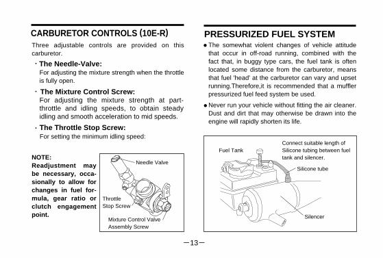
CARBURETOR CONTROLS (10E-R)
The Needle-Valve:
The Mixture Control Screw:
The Throttle Stop Screw:
Three adjustable controls are provided on this carburetor.
For adjusting the mixture strength when the throttle is fully open.
For adjusting the mixture strength at part-throttle and idling speeds, to obtain steady idling and smooth acceleration to mid speeds.
NOTE:Readjustment may be necessary, occa-sionally to allow for changes in fuel for-mula, gear ratio or clutch engagement point.
Needle Valve
Mixture Control ValveAssembly Screw
ThrottleStop Screw
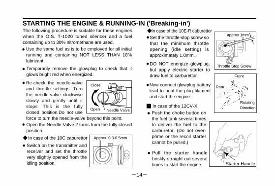
The somewhat violent changes of vehicle attitude that occur in off-road running, combined with the fact that, in buggy type cars, the fuel tank is often located some distance from the carburetor, means that fuel 'head' at the carburetor can vary and upset running.Therefore,it is recommended that a muffler pressurized fuel feed system be used.
Never run your vehicle without fitting the air cleaner. Dust and dirt that may otherwise be drawn into the engine will rapidly shorten its life.
PRESSURIZED FUEL SYSTEM•
•
Silencer
Fuel Tank
Silicone tube
Connect suitable length of Silicone tubing between fueltank and silencer.
For setting the minimum idling speed:
13
¡
¡
¡
approx 1mm
Approx. 0.3-0.5mm
The following procedure is suitable for these engines when the O.S. T-1020 tuned silencer and a fuel containing up to 30% nitromethane are used.
Use the same fuel as is to be employed for all initial running and containing NOT LESS THAN 18% lubricant.
Temporarily remove the glowplug to check that it glows bright red when energized.
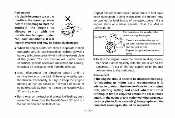
Open the Needle-Valve 2 turns from the fully closed position.
Switch on the transmitter and receiver and set the throttle very slightly opened from the idling position.
DO NOT energize glowplug, but apply electric starter to draw fuel to carburettor.
Now connect glowplug battery lead to heat the plug filament and start the engine.
Re-check the needle-valve and throttle settings. Turn the needle-valve clockwise slowly and gently until it stops. This is the fully closed position.Do not use force to turn the needle-valve beyond this point.
•
•
•
•
Open
Close
Needle Valve
◆ In case of the 10C caburettor
•
◆ In case of the 10E-R caburettor
Set the throttle-stop screw so that the minimum throttle opening (idle setting) is approximately 1.0mm.
•
Throttle Stop Screw•
RotatingDirection
Front
Rear•
STARTING THE ENGINE & RUNNING-IN ('Breaking-in')
■
Starter Handle
In case of the 12CV-X
Push the choke button on the fuel tank several times to deliver the fuel to the carburetor. (Do not over-prime or the recoil starter cannot be pulled.)
Pull the starter handle briskly straight out several times to start the engine.
•
•
14
30º
When the engine starts, first allow it to operate in short runs at the very rich starting settings, with the glowplug battery still connected and with its driving wheels clear of the ground.The rich mixture will, under these conditions, provide adequate lubrication and cooling, indicated by profuse smoke from the exhaust.
Next, disconnect the glowplug battery and try running the car on the track. If the engine stalls, open the throttle fractionally, but try to keep the engine running as rich as possible: if it stops because of being excessively over-rich, close the Needle-Valve 30˚ and try again.
Run the car on the track until one tank of fuel has been consumed, then close the Needle-Valve 30˚ and run the car for another full tank of fuel.
Needle
The position of the needle-valvewhen starting the engine.
Close the needle-valve approx.30˚ after running the vehicle forone full tank of fuel.Repeat this procedure several times.
•
•
•
30º
30º
To stop the engine, close the throttle to idling speed, then shut it off completely with the trim lever on the transmitter. To cut off the fuel supply, pinch the fuel delivery tube to the carburetor.
•
If the engine should need to be disassembled (e.g. for cleaning or minor parts replacement) it is advisable to return the Needle-Valve to the original rich, starting setting and check whether further running-in time is required before the car is raced again. In the event of any major working parts (e,g, piston/cylinder liner assembly) being replaced, the complete running-in should be repeated.
Remember!
It is vitally important to set the throttle at the correct position before attempting to start the engine.If the engine is allowed to run with the throttle too far open under "no load" conditions, it will rapidly overheat and may be seriously damaged.
Remember! Repeat this procedure until 5 more tanks of fuel have been consumed, during which time the throttle may be opened for brief bursts of increased power. If the engine stops at medium speeds, close the Mixture Screw 45-90˚.
15
IF THE ENGINE FAILS TO STARTCheck the following:
Glowplug battery discharged or glowplug defunct.
Fuel not reaching carburetor.
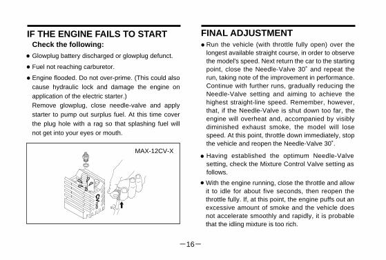
Engine flooded. Do not over-prime. (This could also cause hydraulic lock and damage the engine on application of the electric starter.)Remove glowplug, close needle-valve and apply starter to pump out surplus fuel. At this time cover the plug hole with a rag so that splashing fuel will not get into your eyes or mouth.
••
•
Run the vehicle (with throttle fully open) over the longest available straight course, in order to observe the model's speed. Next return the car to the starting point, close the Needle-Valve 30˚ and repeat the run, taking note of the improvement in performance. Continue with further runs, gradually reducing the Needle-Valve setting and aiming to achieve the highest straight-line speed. Remember, however, that, if the Needle-Valve is shut down too far, the engine will overheat and, accompanied by visibly diminished exhaust smoke, the model will lose speed. At this point, throttle down immediately, stop the vehicle and reopen the Needle-Valve 30˚.
Having established the optimum Needle-Valve setting, check the Mixture Control Valve setting as follows.
With the engine running, close the throttle and allow it to idle for about five seconds, then reopen the throttle fully. If, at this point, the engine puffs out an excessive amount of smoke and the vehicle does not accelerate smoothly and rapidly, it is probable that the idling mixture is too rich.
FINAL ADJUSTMENT•
•
•
MAX-12CV-X
16
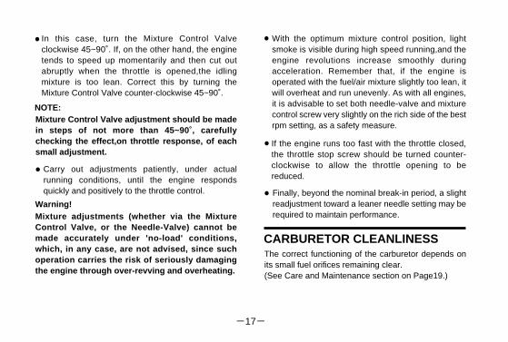
In this case, turn the Mixture Control Valve clockwise 45~90˚. If, on the other hand, the engine tends to speed up momentarily and then cut out abruptly when the throttle is opened,the idling mixture is too lean. Correct this by turning the Mixture Control Valve counter-clockwise 45~90˚.
Warning!
NOTE:Mixture Control Valve adjustment should be made in steps of not more than 45~90˚, carefully checking the effect,on throttle response, of each small adjustment.
Carry out adjustments patiently, under actual running conditions, until the engine responds quickly and positively to the throttle control.
Mixture adjustments (whether via the Mixture Control Valve, or the Needle-Valve) cannot be made accurately under 'no-load' conditions, which, in any case, are not advised, since such operation carries the risk of seriously damaging the engine through over-revving and overheating.
•
•
With the optimum mixture control position, light smoke is visible during high speed running,and the engine revolutions increase smoothly during acceleration. Remember that, if the engine is operated with the fuel/air mixture slightly too lean, it will overheat and run unevenly. As with all engines, it is advisable to set both needle-valve and mixture control screw very slightly on the rich side of the best rpm setting, as a safety measure.
If the engine runs too fast with the throttle closed, the throttle stop screw should be turned counter-clockwise to allow the throttle opening to be reduced.
•
•
• Finally, beyond the nominal break-in period, a slight readjustment toward a leaner needle setting may be required to maintain performance.
CARBURETOR CLEANLINESSThe correct functioning of the carburetor depends on its small fuel orifices remaining clear.(See Care and Maintenance section on Page19.)
17
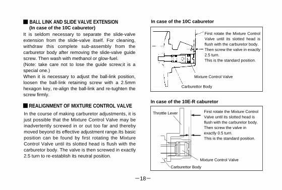
BALL LINK AND SLIDE VALVE EXTENSION
It is seldom necessary to separate the slide-valve extension from the slide-valve itself. For cleaning, withdraw this complete sub-assembly from the carburetor body after removing the slide-valve guide screw. Then wash with methanol or glow-fuel.(Note: take care not to lose the guide screw;it is a special one.)When it is necessary to adjust the ball-link position, loosen the ball-link retaining screw with a 2.5mm hexagon key, re-align the ball-link and re-tughten the screw firmly.
(In case of the 10C caburetor)
REALIGNMENT OF MIXTURE CONTROL VALVE■In the course of making carburetor adjustments, it is just possible that the Mixture Control Valve may be inadvertently screwed in or out too far and thereby moved beyond its effective adjustment range.Its basic position can be found by first rotating the Mixture Control Valve until its slotted head is flush with the carburetor body. The valve is then screwed in exactly 2.5 turn to re-establish its neutral position.
Mixture Control Valve
Carburettor Body
First rotate the Mixture Control Valve until its slotted head is flush with the carburetor body.Then screw the valve in exactly 2.5 turn. This is the standard position.
■ In case of the 10C caburetor
In case of the 10E-R caburetor
Carburettor Body
Mixture Control Valve
First rotate the Mixture Control Valve until its slotted head is flush with the carburetor body.Then screw the valve in exactly 0.5 turn. This is the standard position.
Throttle Lever
18
4.CARE AND MAINTENANCE1.
2.
3.
The minute particles of foreign matter, that are present in any fuel may, by accumulating and partially obstructing fuel flow, cause engine performance to become erratic and unreliable.O.S. 'Super-Filters' (large and small) are available, as optional extras, to deal with this problem. One of these filters, fitted to the outlet tube inside your refueling container, will prevent the entry of foreign material into the fuel tank. It is also recommended that a good in-line filter be installed between the tank and carburetor.
Do not forget to clean the filters regularly to remove dirt and lint that accumulate on the filter screens. Also, clean the carburetor itself occasionally.
At the end of each operating session, drain out any fuel that may remain in the fuel tank. Afterwards,energize the glow-plug and try to restart the engine, to burn off any fuel that may remain inside the engine. Repeat this procedure until the engine fails to fire. Do this while the engine is still warm.
Then, inject some after-run oil into the engine, and rotate the engine with an electric starter for 4 to 5 seconds to distribute the oil to all the working parts.
Note:
5.
Do not inject after-run oil into the carburetor as this may cause the O-rings inside the carburetor to deteriorate. These procedures will reduce the risks of starting difficulties or corrosion after a period of storage.
Finally, when cleaning the exterior of the engine, use methanol or kerosene. Do not use gasoline or any solvent that might damage the silicone fuel tubing.
Caution: The rear crankshaft bearing of this engine uses a special plastic retainer. If the front housing needs to be heated to remove or replace the bearing, do not allow the bearing to exceed 120˚C (248˚F), otherwise it may be damaged and rendered unserviceable.
19
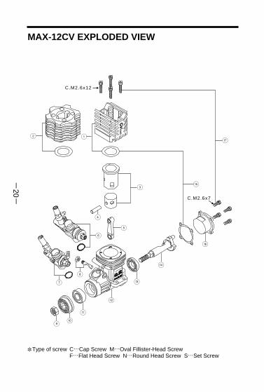
MAX-12CV EXPLODED VIEW
Type of screw C…Cap Screw M…Oval Fillister-Head ScrewF…Flat Head Screw N…Round Head Screw S…Set Screw
✽
12
3
4
5
6
7
8
90
-
=
q
w
e
r
t
C.M2.6x12
C.M2.6x7
20
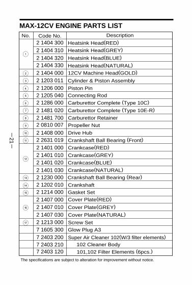
MAX-12CV ENGINE PARTS LIST
The specifications are subject to alteration for improvement without notice.
e
w
q
=
-
0
9
8
7
6
5
4
3
2
1
7 2403 1207 2403 210
2 1407 0002 1214 0002 1202 0102 1230 000
7 2403 2007 1605 3002 1213 000
2 1401 0002 2631 0192 1408 000
2 0810 0072 1481 7002 1481 0202 1286 0002 1205 0402 1206 0002 1203 011
2 1404 300
r
t
102 Cleaner Body
101,102 Filter Elements (6pcs.)
Super Air Cleaner 102(W/3 filter elements)
Screw Set
Glow Plug A3
Gasket Set
Crankshaft
Crankshaft Ball Bearing (Rear)
Crankcase(RED)Crankshaft Ball Bearing (Front)
Carburettor Retainer
Carburettor Complete (Type 10C)Connecting Rod
Piston Pin
Cylinder & Piston Assembly
Heatsink Head(RED)DescriptionCode No.
Carburettor Complete (Type 10E-R)
Propeller Nut
Drive Hub
Cover Plate(RED)
Heatsink Head(GREY)
No.
2 1404 3102 1404 320 Heatsink Head(BLUE)
2 1404 330 Heatsink Head(NATURAL)
2 1404 000 12CV Machine Head(GOLD)
2 1401 010 Crankcase(GREY)
2 1401 020 Crankcase(BLUE)
2 1401 030 Crankcase(NATURAL)
2 1407 010 Cover Plate(GREY)
2 1407 030 Cover Plate(NATURAL)
21

MAX-12CV-X EXPLODED VIEW
Type of screw C…Cap Screw M…Oval Fillister-Head ScrewF…Flat Head Screw N…Round Head Screw S…Set Screw
✽
12
3
4
56
7
8
90
-
=
q
w
e
rt
C.M2.6x12
M.M2.6x7
y
u
u-1u-2
M.M2.6x7
22
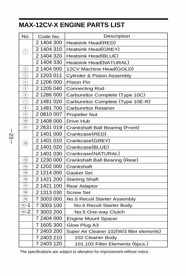
MAX-12CV-X ENGINE PARTS LIST
The specifications are subject to alteration for improvement without notice.
ew
q
=
-09
87654
32
1
7 2403 1207 2403 210
2 1421 2002 1214 0002 1202 0002 1230 000
7 2403 2007 1605 300
2 1401 0002 2631 0192 1408 0002 0810 0072 1481 7002 1481 0202 1286 0002 1205 0402 1206 0002 1203 011
2 1404 300
rt
102 Cleaner Body
101,102 Filter Elements (6pcs.)
Super Air Cleaner 102(W/3 filter elements)
Screw Set
Glow Plug A3
Gasket Set
Crankshaft
Crankshaft Ball Bearing (Rear)
Crankcase(RED)Crankshaft Ball Bearing (Front)
Carburettor Retainer
Carburettor Complete (Type 10C)Connecting Rod
Piston Pin
Cylinder & Piston Assembly
Heatsink Head(RED)DescriptionCode No.
Carburettor Complete (Type 10E-R)
Propeller Nut
Drive Hub
Starting Shaft
Heatsink Head(GREY)
No.
2 1404 3102 1404 320 Heatsink Head(BLUE)
2 1404 330 Heatsink Head(NATURAL)
2 1404 000 12CV Machine Head(GOLD)
2 1401 010 Crankcase(GREY)
2 1401 020 Crankcase(BLUE)
2 1401 030 Crankcase(NATURAL)
2 1421 100 Rear Adaptor
2 1313 030y
uu-1u-2
7 3003 000 No.5 Recoil Starter Assembly
7 3003 100 No.5 Recoil Starter Body
7 3003 200 No.5 One-way Clutch
7 2404 000 Engine Mount Spacer
23

The specifications are subject to alteration for improvement without notice.Type of screw
C…Cap Screw M…Oval Fillister-Head ScrewF…Flat Head Screw N…Round Head Screw S…Set Screw
✽
10C CARBURETOR EXPLODED VIEW & PARTS LIST
No.
Carburettor Rubber Gasket
Ball Link No.4
Dust Cover
Metering Needle Assembly
Slide Valve
Slide Valve Guide Screw
Carburetor Body
"O" Ring (2pcs.)
Needle Valve Assembly
Throttle Stop Screw
"O" Ring(S) (2pcs.)
"O" Ring(L) (2pcs.)
Mixture Control Valve Assembly
DescriptionCode No.
5
4
32
1
9
7
6
8
0
1-11-2
3-1
C.M3.5x8
2 2615 000
2 2781 800
4 6066 319
2 1285 600
2 1285 640
2 7881 820
2 1285 901
2 1285 220
2 1286 100
2 1286 200
2 1286 400
2 1881 320
2 3818 420
0
9
8
7
6
5
4
3
2
1
3-1
1-1
1-2
24
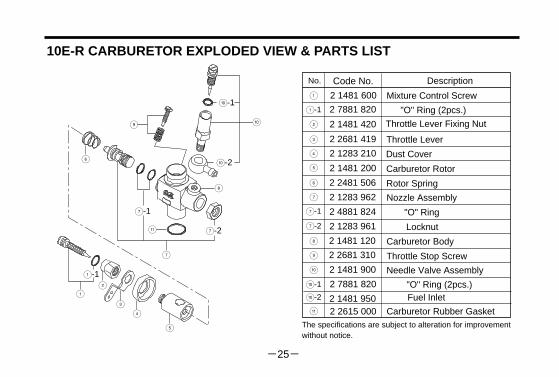
The specifications are subject to alteration for improvement without notice.
10E-R CARBURETOR EXPLODED VIEW & PARTS LIST
2 1481 950
2 7881 820
2 1481 900
2 2681 310
2 1481 120
2 1283 961
2 4881 824
2 1283 962
2 2481 506
2 1481 200
2 1283 210
2 2681 419
2 1481 420
2 1481 600
-
0-1
0
9
8
7
6
5
4
3
2
1
7-1
7-2
0-2
2 2615 000
No.
Carburetor Rubber Gasket
Dust Cover
Carburetor Body
"O" Ring (2pcs.)
Needle Valve Assembly
Throttle Stop Screw
Mixture Control Screw
DescriptionCode No.
Throttle Lever Fixing Nut
1-1 2 7881 820
Throttle Lever
Carburetor Rotor
Rotor Spring
Nozzle Assembly
"O" Ring
Locknut
"O" Ring (2pcs.)Fuel Inlet
5
43
21
9
7
6
8
-
0-1
0
1-1
7-1
7-2
0-2
25

■
RACING ENGINE PARTS
(71608001)
(71605300)
(71605100)
■
(72103110) (72103120)
■
(72103020)
■(72103310)
■
(71530100)
■
(71521000)
■(72403202)
■(72403120)
(72103130)
(72103140)
O.S. GENUINE PARTS & ACCESSORIES
O.S. Glow Plug Exhaust Header PipesFor Kyosho Super10
For Kyosho Spider & HPI Nitro
For Tamiya TG10
For Tamiya TGXNo.8
A3
A5
Super Air Cleaner 102S
101,102 Filter Elements(6pcs.)
Super Joint Tube 15T-1020 Tuned Silencer
Crankshaft Clamp1012
Long Socket WrenchWith Plug Grip
■ 10C Automatic Carburettor
(21286000)
■ 12CV Machine Head
(72001110)BLUE(72001100)RED
φ3 (73300305)
φ7 (73300712)
φ10 (73301012)
Dust Cap Set■
For Carburettor Nipple
For T-1020 Tuned Silencer
For 10C,10E-R Carburettor
For Mugen MTX(72103150)
(72103160)For Kyosho V-ONE R,S
26
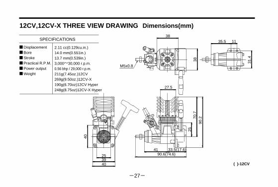
■ Displacement■ Bore■ Stroke■ Practical R.P.M.■ Power output■ Weight
SPECIFICATIONS
12CV,12CV-X THREE VIEW DRAWING Dimensions(mm)
2.11 cc(0.129cu.in.)14.0 mm(0.551in.)13.7 mm(0.539in.)3,000~30,000 r.p.m.0.56 bhp / 29,000 r.p.m.211g(7.45oz.)12CV269g(9.50oz.)12CV-X190g(6.70oz)12CV Hyper248g(8.75oz)12CV-X Hyper
253940
40
41 33.5(17.6)90.6(74.6)
27.5
2570
.790
.2
38
38
M5x0.8
35.5 11
31.4
( )-12CV
27

MEMO
28

C Copyright 2000 by O.S.Engines Mfg. Co., Ltd. All rights reserved. Printed in Japan.
120104
TEL. (06) 6702-0225FAX. (06) 6704-2722
6-15 3-Chome Imagawa Higashisumiyoshi-ku Osaka 546-0003, Japan
URL : http://www.os-engines.co.jp
UNEQ
UA
LLED QUALITY PRECISION & PERFORM
ANCE
ESTABLISHING THE STANDARDS OF EXCELLE
NCE