Embed Size (px)
Citation preview
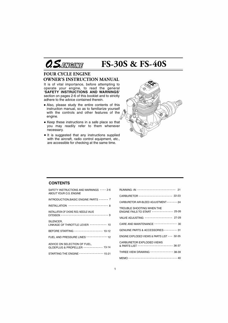
It is of vital importance, before attempting to operate your engine, to read the general 'SAFETY INSTRUCTIONS AND WARNINGS' section on pages 2-6 of this booklet and to strictly adhere to the advice contained therein.
Also, please study the entire contents of this instruction manual, so as to familiarize yourself with the controls and other features of the engine.
Keep these instructions in a safe place so that you may readily refer to them whenever necessary.
It is suggested that any instructions supplied with the aircraft, radio control equipment, etc., are accessible for checking at the same time.
1
2-6
7
8
9
10-12
13-14
15-21
21
27-29
30
31
10
12
SAFETY INSTRUCTIONS AND WARNINGS ABOUT YOUR O.S. ENGINE
INTRODUCTION,BASIC ENGINE PARTS
INSTALLATION
INSTALLATION OF CHOKE ROD, NEEDLE VALVE EXTENSION
SILENCER,LINKAGE OF THROTTLE LEVER
BEFORE STARTING
FUEL AND PRESSURE LINES
ADVICE ON SELECTION OF FUEL,GLOEPLUG & PROPELLER
STARTING THE ENGINE
CONTENTS
RUNNING -IN
CARBURETOR
CARBURETOR AIR-BLEED ADJUSTMENT
TROUBLE SHOOTING WHEN THE ENGINE FAILS TO START
VALVE ADJUSTING
CARE AND MAINTENANCE
GENUINE PARTS & ACCESSORIES
ENGINE EXPLODED VIEWS & PARTS LIST
CARBURETOR EXPLODED VIEWS& PARTS LIST
THREE VIEW DRAWING
MEMO
22-23
24
25-26
32-35
36-37
38-39
40

2
Remember that your engine is not a "toy", but a highly efficient internal-combustion machine whose power is capable of harming you, or others, if it is misused.As owner, you, alone, are responsible for the safe operation of your engine, so act with discretion and care at all times.If at some future date, your O.S. engine is acquired by another person, we would respectfully request that these instructions are also passed on to its new owner.
SAFETY INSTRUCTIONS AND WARNINGS ABOUT YOUR O.S. ENGINE
The advice which follows is grouped under two headings according to the degree of damage or danger which might arise through misuse or neglect.
WARNINGS NOTES
These cover events which might involve serious (in extreme circumstances, even fatal) injury.
These cover the many other possibilities, generally less obvious sources of danger, but which, under certain circumstances, may also cause damage or injury.
3
WARNINGS
Model engine fuel is poisonous. Do not allow it to come into contact with the eyes or mouth. Always store it in a clearly marked container and out of the reach of children.
Never operate your engine in an en-closed space. Model engines, like auto-mobile engines, exhaust deadly carbon-monoxide. Run your engine only in an open area.
Model engines generate considerable heat. Do not touch any part of your engine until it has cooled. Contact with the muffler (silencer), cylinder head or exhaust header pipe, in particular, may result in a serious burn.
Never touch, or allow any object to come into contact with, the rotating propeller and do not crouch over the engine when it is running.
A weakened or loose propeller may disintegrate or be thrown off and, since propeller tip speeds with powerful engines may exceed 600 feet(180 metres) per second, it will be understood that such a failure could result in serious injury, (see 'NOTES' section relating to propeller safety).
Model engine fuel is also highly flammable. Keep it away from open flame, excessive heat, sources of sparks, or anything else which might ignite it. Do not smoke or allow anyone else to smoke, near to it.

4
NOTESThis engine was designed for model aircraft. Do not attempt to use it for any other purpose.
Mount the engine in your model securely, following the manufacturers' recommenda-tions, using appropriate screws and lock-nuts.
Be sure to use the silencer (muffler) supplied with the engine. Frequent exposure to an open exhaust may eventually impair your hearing. Such noise is also likely to cause annoyance to others over a wide area.
Install a top-quality propeller of the diameter and pitch specified for the engine and aircraft. Locate the propeller on the shaft so that the curved face of the blades faces forward-i.e. in the direction of flight. Firmly tighten the propeller nut, using the correct size wrench.
If you remove the glowplug from the engine and check its condition by connecting the battery leads to it, do not hold the plug with bare fingers.Use an appropriate tool or a folded piece of cloth.
5
NOTESAlways check the tightness of the propeller nut and retighten it, if necessary, before restarting the engine, particularly in the case of four-stroke-cycle engines. If a safety locknut assembly is provided with your engine, always use it. This will prevent the propeller from flying off in the event of a "backfire", even if it loosens.
If you install a spinner, make sure that it is a precision made product and that the slots for the propeller blades do not cut into the blade roots and weaken them.
Preferably, use an electric starter. The wearing of safety glasses is also strongly recommended.
Discard any propeller which has become split, cracked, nicked or otherwise rendered unsafe. Never attempt to repair such a propeller: destroy it. Do not modify a propeller in any way, unless you are highly experienced in tuning propellers for specialized competition work such as pylon-racing.
Take care that the glow plug clip or battery leads do not come into contact with the propeller. Also check the linkage to the throttle arm. A disconnected linkage could also foul the propeller.
After starting the engine, carry out any needle-valve readjustments from a safe position behind the rotating propeller. Stop the engine before attempting to make other adjustments to the carburetor.

6
NOTESAdjust the throttle linkage so that the engine stops when the throttle stick and trim lever on the transmitter are fully retarded. Alternatively, the engine may be stopped by cutting off the fuel supply. Never try to stop the engine physically.
Take care that loose clothing (ties, shirt sleeves, scarves, etc.)do not come into contact with the propeller.Do not carry loose objects (such as pencils, screwdrivers, etc.) in a shirt pocket from where they could fall through the propeller arc.
Do not start your engine in an area containing loose gravel or sand. The propeller may throw such material in your face and eyes and cause injury.
For their safety, keep all onlookers (especially small children) well back (at least 20 feet or 6 meters) when preparing your model for flight. If you have to carry the model to the take-off point with the engine running, be especially cautious. Keep the propeller pointed away from you and walk well clear of spectators.
Warning! Immediately after a glowplug-ignition engine has been run and is still warm, conditions sometimes exist whereby it is just possible for the engine to abruptly restart if the propeller is casually flipped over compression WITHOUT the glowplug battery being reconnected. Remember this if you wish to avoid the risk of a painfully rapped knuckle!
7
Silencer BodyChoke rod
FS-40SFS-30S
INSTALLING THE GLOWPLUG
Carburetor
Install washer on glowplug and insert carefully into cylinder-head, making sure that it is not cross-threaded before tightening firmly.
BASIC ENGINE PARTSThe FS Series engines are up-to-date overhead-valve four-stroke-cycle engines for model aircraft use and are the outcome of a long period of technical development. The FS Series engines are produced by the world's oldest and largest model engine manufacturing company; a company which also pioneered the quantity production of model four-cycle engines.
Drive Hub
Crankcase
Rocker Cover
Glow plugWasher
Standard Accessories
F-2010 Silencer Assembly
Exhaust pipe
Propellernut
PropellerWasher
Cover plate
Glow plug
Fuel inlet
Breather nipple
This manual handles the following two versions.FS-30S, FS-40S
Lock nut
Beam Mount
FS-30S
Please note that this engine is not supplied with any tools (e.g. Allen keys, wrenches, etc.)
Glow plug TypeFGlow plug TypeF

8
INSTALLATION How to fasten the mounting screws.
Hardwood mounting beams
O.S. radial motor mount(cast aluminum)
Tighten second nut firmlydown onto first nut.
Tighten this nut first.
Steel washer
3.5mm steel nutsfor FS-40SSpring washer or lock washer
Hardwood such as cherry or maple.
Spring washer
3.5mm steel Allen screwfor FS-40S
Front view
CORRECT
Side view
Top surfaces are in the same plane.
Re-align the surfaces as necessary
INCORRECT
Top surfaces are not in the same plane. Opposite beam
Top surfaces are not in the same plane.
Engine does not rest firmly.
Rigid hardwood(e.g. maple)
At least15mm(19/32") for FS-40S
At least 12mm(1/2") for FS-30S
Installation in the modelA typical method of beammounting is shown below,left.
O.S. radial motor mount(Available as an optional extra part. See parts list)
Make sure that the mounting beams are parallel and that their top surfaces are in the same plane.
3mm steel nutsfor FS-30S
3mm steel screwfor FS-30S3.5mm steel screwfor FS-40S
3mm steel Allen screwfor FS-30S
At least 12mm(1/2") for FS-30S
At least15mm(19/32") for FS-40S
9
The FS Series engines are equipped with self-reopening choke valves.Cut the choke rod (supplied) to the length indicated, then secire the rod by tightening the set screw, using 1.5mm Allen wrench, after installing the engine.
INSTALLATION OF CHOKE ROD
Choke rod1.5mmAllen key
Set-screw
Choke rod
approx.7mm approx.
2mm
Frame sides of fuselage
NEEDLE VALVE EXTENSION
Set-screw
1.5mm Allen key
Releasing the choke rod allows the choke valve to open.
(FS-40S)The needle-valve supplied with these engines is designed to incorporate an extension so that, when the engine is enclosed within the fuselage, the needle-valve may be adjusted from the outside. Cut a commercially available rod to the required length, bend one end to an L shape, insert it into needle's center hole and secure it by tightening the set-screw in the needle-valve knob with 1.5mm. Allen key.

10
SILENCERInstallation for FS-30S and FS-40SScrew the exhaust header pipe into the exhaust port until it "bottoms", then unscrew it just sufficiently to achieve the required exhaust outlet angle. Secure the pipe in this position by tightening the locknut firmly against the cylinder head with the wrench supplied. Then, screw the silencer onto the end of the header pipe and tighten locknut firmly. Re-check tightness of locknuts when engine is hot.
LINKAGE OF THROTTLE LEVERFirst, ensure that the throttle rotor is fully closed when the throttle-lever is in the closed position. Adjust rotor stop screw if necessary. Then couple the lever to the throttle-servo so that the rotor is fully closed when the transmitter throttle stick and trim lever are in the fully retarded position.
BEFORE STARTINGTools, accessories, etc.The following items are necessary for operating the engine.
1 FuelModel glowplug engine fuel of good quality, preferably containing a small percentage of nitromethane. (See "Advice on selection of fuel, glowplug and propeller")
2 GlowplugO.S. Type F glowplug is supplied with the engine.
3 PropellerSuggested propellers are shown in the ADVICE ON SELECTION OF FUEL & PROPELLER section.
4 Glowplug batteryThe power source for heating the glowplug may be a 1.2volt Ni-cd battery a large heavy-duty 1.5volt dry cell, or a 2-volt rechargeable lead-acid cell (accumulator).
11
1.5 volt heavy-dutydry battery
or 2 volt rechargeablelead-acid cell (at least 5Ah)
If a 2-volt cell is employed, use a resistance wire, as shown, to reduce applied voltage, otherwise element will overheat and burn out.
Resistance coil(nichrome wire)
Adjust applied voltage by changing the position of clip on resistance coil until glowplug element is glowing bright red.
Battery leads
Raise
voltage to
increase
brightness.
Lower voltage to
reduce brightness.
Warning (Very hot)Never touch the nichrome wire while the battery is connected.
5 Plug wrenchUsed for tightening glowplug. The O.S. long plug wrench is available as an optional accessory. For tightening
glowplug
Battery leads
6 Battery leadsThese are used to conduct current from the battery to the glowplug. Basically, two leads, with clips, are required, but, for greater conve-nience, twin leads with special glowplug connectors, as shown on the right, are commercially available.
7 Fuel tankFor installation in the model, a 150cc(5oz.) for FS-30S and FS-40S tank is suggested.These will allow 10 minute flight.
8 Fuel bottle or pumpFor filling the fuel tank, a simple, polyethylene "squeeze" bottle, with a suitable spout,is all that is required. Alternatively, one of the purpose-made manual or electric fuel pumps may be used to transfer fuel directly from your fuel container to the fuel tank.
Fuel bulb
Manual
Electric
Fuel pumps

12
Fuel Can Filter
3
11 Silicone tubingThis is required for the connection between the fuel tank and engine.
10 Fuel can filterInstall a filter in the outlet line of your refuelling container to prevent entry off oreign matter into the fuel tank. (Refer to of STARTING THE ENGINE section.)
9 Electric starter and starter batteryAn electric starter is recommended for starting.
FUEL AND PRESSURE LINES
Fuel level
Muffler to tank pressure line
Connect suitable lengths of silicone tubing, as illustrated, after installing the engine.
Attention to tank height
Note: When cutting silicone tubing···
Locate the fuel tank so the top of the tank is5-10mm(1/4-3/8") above the level of theneedle-valve.
5-10mm
Silicone tubing
Use knife or razor blade
Do not use wire cutters or pliers.
*If you should need to clean the silicone tubing, use methanol or glow-fuel, not gasoline or kerosene.
Silencer (muffler) pressurized fuel systemTo reduce variation in fuel "head" and ensure steady fuel delivery at the carburetor, it is advisable to employ a silencer (muffler) pressurized fuel system, i.e. to use the silencer outlet nipple to pressurize the fuel tank as shown at left.
13
FuelUse a good quality commercial fuel or one of the blends shown in the table. Fuel "A" is suitable for running-in and ordinary use. Fuel "B" is for use when more power is required and for improved flexibility. Note that even a small quantity of nitromethane (3-5%) will improve flexibility, making the needle-valve adjustment less critical and improving throttle response. Use only materials of the highest purity. Synthetic oils are permissible but are less tolerant of a "lean run" than castor-oil. If, therefore, a synthetic lubricant is used in the fuel, readjust the needle-valve to a slightly richer setting, as a safety measure, in case the fuel/air mixture becomes too lean through maneuvers in flight. If a higher nitro fuel is used, the engine should be checked out to make sure that it is sufficiently run-in to operate on that particular fuel without overheating. Do not use fuels containing less than 18% lubricant.
ADVICE ON SELECTION OF FUEL, GLOWPLUG & PROPELLER A B75%
20%
5%
65%
20%
15%
Methanol
Castor Oil
Nitromethane
Model engine fuel is poisonous. Do not allow it to come into contact with the eyes or mouth. Always store it in a clearly marked container and out of the reach of children.
Model engine fuel is also highly flammable. Keep it away from open flame, excessive heat, sources of sparks, or anything else which might ignite it. Do not smoke, or allow anyone else to smoke, near to it.
Reminder!
PROPELLERSuggested propeller sizes are given in the table. As the ideal propeller diameter, pitch and blade area vary according to the size, weight and type of model, final propeller selection will require in flight experimentation.
Never touch, or allow any object to come into contact with, the rotating propeller and do not crouch over the engine when it is running.
Reminder!

14
Trainer & ScaleSport & Aerobatic
GLOWPLUGThe FS-30S and FS-40S are supplied with an O.S. Type F glowplug, specially designed for O.S. four-stroke engines.
The role of the glowplugWith a glowplug engine, ignition is initiated by the application of a 1.5-volt power source. When the battery is disconnected, the heat retained within the combustion chamber remains sufficient to keep the plug filament glowing, thereby continuing to keep the engine running. Ignition timing is 'automatic' : under reduced load, allowing higher rpm, the plug becomes hotter and, appropriately, fires the fuel/air charge earlier; conversely, at reduced rpm, the plug become cooler and ignition is retarded.
FS-40S 10x7-7.5, 11x6 10x7, 10.5x6, 11x712x5-6
Install a plug suitable for the engine.Use fuel containing a moderate percentage of nitromethane unless more is essential for racing events.Do not run the engine too lean and do not leave the battery connected while adjusting the needle.
However, plug life can be extended and engine performance maintained by careful use, i.e.:
Apart from when actually burned out, a plug may need to be replaced because it no longer delivers its best performance, such as when:
When to replace the glowplug
Filament surface has roughened and turned white. Filament coil has become distorted.Foreign matter has adhered to filament or plug body has corroded.Engine tends to cut out when idling.Starting qualities deteriorate.
Glowplug lifeParticularly in the case of very high performance engines, glowplugs must be regarded as expendable
FS-30S 9x6-7, 10x4 10x5-6
15
STARTING THE ENGINEPreparations
1 Installing the glowplugInstall the washer on the glowplug and screw carefully into cylinder-head, making sure that it is not cross-threaded before tightening firmly. Washer
Glow plug
2 Installing the propellerThere is a risk, particularly with four-stroke engines, of the propeller flying off if the propeller nut loosens due to detonation or "knocking" when the engine is run too lean or under too heavy a load. To prevent this from happening, it is recommended to use the special Propeller Locknut Set (optional extra) with the FS-40S.
Wrench
Tighten the propeller nut firmly so that compression is first felt around this position(i.e. with blades horizontall) when turning the propeller in the direction of arrow.
3 Filling the fuel tank
Re-connect fuel line to engine after tank is filled.
Disconnect fuel line from the fuel inlet, and connect it to the tubing from the fuel pump.
Do not let dirt or dust enter fuel can.
Fuel (model glow-plug engine fuel)
Fuel pump
Use a fuel can filter (e.g. O.S. Super Filter).

16
Close
Open
4 Opening and closing of the needle-valve
Turn needle-valve clockwise to close (for leaner mixture).Turn needle-valve counter-clockwise to open (for richer mixture).
Starting
Turn the needle-valve in the direction of arrow slowly, without forcing, until it stops. The position where the needle-valve stops is the fully closed position. It may be convenient to remember the position of the mark or set-screw at this time.
5 Setting the needle-valve
Set-screw
Turn the needle-valve in the direction of arrow from the closed position.FS-30S (2 to 2-1/2 turns)FS-40S (2-1/2 to 3 turns)
6 Open the throttle fully
Fully closed positionFully opened position
Throttle
OpenClose
Fuel will flow from tank tocarburetor as propeller isturned.
Close the air intakeby operating thechoke control.(FS-40S)
Turn the propellerfour revolutionswhile watchingfuel line.
Turn the propeller 3 to 4 turns counter-clockwise smartly by finger in the direction of arrow. Turn approx. 10 turns when the engine is cold.
7 Priming
17
8 Hold model securely when starting
9 Setting the throttle
10 Heat glowplug
Starter
Assistant should hold the model so that it cannot move forward when the engine starts.
Be careful not to be hit by propeller!
Fully openedposition
Fully closedposition
Set at this Position.
Starting battery
Connect battery leads as shown(polarity is immaterial.)
11 Apply electric starter
Assistant
Glowplug battery.Place as far to therear as possible.

18
Check that the throttle is one-third open from the fully closed position. Bring the starter into contact with the spinner nut or spinner and depress the starter switch for one or two seconds. Repeat if necessary. When the engine fires, withdraw the starter immediately.
Attention: Never place your finger over the carburetor intake when applying the starter. Such an action will cause an excess quantity of fuel to be drawn into the cylinder and result in hydraulic lock that may damage the engine.
BEWARE ofthe rotatingpropeller.
12 Engine starts
In the interests of safety, keep your face and other parts of the body away from the vicinity of the propeller.
Listen to the sound carefully.
13 Needle-valve adjustment(1)Slowly advance throttle to its fully open position, then gradually close the needle-valve until the exhaust sound changes pitch.
Close the needle-valve gradually until a high-pitched exhaust note begins to be superimposed on the lower-pitched sound.
14 Disconnect battery leads
Disconnect the battery leads from the engine with care so that the plug clip does not touch the rotating pro-peller.
If the engine stops when battery leads are disconnected, close the needle-valve a little (approx. 45˚) further, and restart the engine.
19
20-30˚
15 Needle-valve adjustment(2)
As the needle-valve is closed beyond the initial readjustment, the rpm of the engine will be increased and a continuous high-pitched exhaust note, only, will be heard.
Key to the needle-valve adjustment.(Turn 15-30˚ at a time.)
Turn the needle-valve 15-30˚ in the direction of arrow, and wait momentarily for the change of r.p.m.After the rpm of the engine increases, turn the needle-valve another 10-15˚ and wait for the next change of r.p.m.
As the speed of the engine does not instantly change with needle-valve readjustment, small movements, with pauses between, are necessary to arrive at the optimum setting.
16 Needle-valve adjustment(Summary)
Practical best(optimum) needle-valve setting
Disconnect battery leads from glowplug at about this point.
Maximum rpm setting("Lean").
"Rich" needle-valve setting when starting the engine.
Enginestops
R
evolu
tion
ssta
rtt
to
decr
ease.to
de
The engine may stop if the battery leads are disconnected from the glowplug while the engine is running rich.
NOTE:The above sketch is for reference purposes only.Actual needle positions may differ from those shown.

20
On starting from cold, with the needle-valveset at the rich starting position:
Take note of this position of the needle-valve.
This will produce the practical best (i.e. optimum)rpm setting (lower than maximum rpm).A light grey exhaust emission may be observed.
Now, re-open needle-valve 20-30 degree
maximum rpm is reached and will fall off (or engine will stop) if needle -valve is closed any further. Exhaust gas will be very light.
Finally:
rpm will increase and exhaust smoke will be reduced.
Further needle-valve closure:
Exhaust smoke will be less dense and grey in color.
As the needle-valve is closed and the r.p.m. increases
a good deal of white smoke is emitted.
Once the optimum needle-valve setting has been established (see "Needle-valve adjustment-Summary") the procedure for starting is simplified as follows:1) Open the needle-valve one half-turn (180˚) from
the optimum setting.2) Open the throttle fully, place your finger over the
carburettor intake and rotate the propeller through two revolutions to prime the engine.
3) Set the throttle one-third open from the fully closed position, energize the glowplug and apply the starter. When the engine starts, re-open the throttle and re-adjust the needle-valve to the optimum setting.
Subsequent starting procedure
16
Note: When re-starting the engine on the same day, provided that atmospheric conditions have not changed significantly, it may be practicable to re-start the engine on its optimum (running) setting. Also, if the engine is being re-started immediately after a run (i.e.hot), priming should not be necessary.
21
17 How to stop the engine
Close the throttle to reduce to the lowest possible r.p.m.
Close
With the transmitter throttle trim lever fully retarded, adjust the throttle servo linkage so that the throttle rotor is fully closed (i.e.engine stopped) when the stick is fully retarded.
All internal-combustion engines benefit, to some degree, from extra care when they are run for the first few times - known as running-in or breaking-in. This is because the working parts of a new engine take a little time to settle down after being subjected to high temperatures and stresses. However, because O.S. engines are made with the aid of the finest modern precision machinery and from the best and most suitable materials, only a very short and simple running-in procedure is required and can be carried out with the engine installed in the model.The process is as follows:1) Start the engine and, with the throttle fully open,
open the needle-valve an extra half turn (180˚) from the optimum setting. This will produce a rich mixture that will result in cooler running. Allow the engine to run out a full tank on the ground. (Avoid dusty surroundings.)
2) Now fly the model with the needle-valve re-set 20-30 degrees open from the optimum setting ( i.e. 40-60˚ from the highest rpm setting ).
3) Close the needle-valve very slightly on successive flights so that the engine is running on its optimum needle setting at the fifth or sixth flight.
RUNNING-IN ("Breaking-in")

22
These engines are equipped with a throttle type car-buretor which provides a wide range of engine speed control. With the throttle lever linked to a suitable servo in the model, movement of the throttle control on the transmitter will enable engine to be varied, proportionally, from idling speed to full power.The carburetor of your engine has been factory set for the approximate best results and no adjustment (except to the needle-valve) should be required provided that the fuel tank is correctly located, as previously described. After the engine has been run-in, check the operation of the throttle according to the following chart. Re-adjust the controls only when necessary.
CARBURETOR
23
Sta
rt th
e en
gine
.
Mak
e su
re th
at th
e th
rottl
e is
fully
ope
n.
Adj
ust t
he n
eede
-val
ve.
Clo
se th
e th
rottl
e gr
adua
lly.
Fin
d th
e id
ling
posi
tion.
Fix
the
idlin
g po
sitio
n.
Ope
n th
e th
rottl
e fu
lly.
Doe
s th
e en
gine
rega
in fu
ll po
wer
?
Con
tinue
run
ning
at h
igh
spee
dfo
r 10
sec
onds
.
Clo
se th
e th
rottl
e.
Run
at i
dlin
g sp
eed
for
5 se
cond
s.
Doe
s th
e en
gine
sto
p?
App
ly fu
ll th
rottl
e.
Doe
s th
e en
gine
rega
in fu
ll po
wer
imm
edia
tely
?
OK
Ref
er to
the
CA
RB
UR
ET
OR
AIR
-BLE
ED
AD
JUS
TM
EN
Tse
ctio
n on
pag
e 24
.
Re-
set t
he id
ling
posi
tion
ata
little
hig
her
r.p.
m.
Se
t th
e t
hro
ttle
op
en
ing
by
mea
ns o
f th
e th
rott
le t
rim
on
the
trans
mitt
er s
o th
at th
e lo
wes
tpr
actic
al s
peed
, with
out r
isk
ofth
e en
gine
sto
ppin
g,is
obt
aine
d.
The
pos
ition
whe
re th
e lo
wes
tp
oss
ible
r.p
.m.
,wit
h s
tea
dy
runn
ing,
is o
btai
ned.
20-3
0˚ o
pen
from
max
imum
r.p.
m. s
ettin
g.
Yes
.
No.
Yes
.
Eng
ine
stop
s.
Eng
ine
stop
s.
Eng
ine
stop
s.

24
CA
RB
UR
ET
OR
AIR
-BL
EE
D A
DJU
ST
ME
NT
Sta
rt e
ngin
e an
d ad
just
nee
dle-
valv
e as
pre
viou
sly
desc
ribed
.
Clo
se th
e th
rottl
e gr
adua
lly.
Fin
d th
e id
ling
posi
tion.
Hol
d th
e m
odel
.
Hol
d m
odel
leve
l, th
en s
low
ly r
aise
its
nose
.
If r
pm
incr
ease
s.If
en
gin
e ru
ns
un
even
ly o
r st
op
s.
Imm
edia
tely
poi
ntno
se d
own,
so
that
engi
ne r
uns
stea
dily
agai
n.
Sto
p th
e en
gine
.
Sto
p th
e en
gine
.
Not
e: S
top
engi
ne b
ypi
nchi
ng fu
el li
neD
o no
t tou
chne
edle
-val
ve.
Ope
n ai
r-bl
eed
scre
w.
Hal
f tur
n at
atim
e.
Clo
se a
ir-bl
eed
scre
w.
Hal
f tur
n at
a
time.
Pre
-Flig
ht
Ch
eck
Repeat the procedure while opening and closingthe throttle until the best result is obtained.
Att
enti
on
: D
o n
ot
leav
e th
e g
low
plu
g c
on
nec
ted
to
th
e b
atte
ry w
hile
ad
just
ing
th
e ca
rbu
reto
r th
rott
le.
The
se a
djus
tmen
ts c
an b
e m
ade
with
out s
topp
ing
the
engi
ne.
How
ever
, it i
s ad
visa
ble
for
begi
nner
s to
sto
p th
e en
gine
fo
r sa
fety
rea
sons
.
appr
ox.
15˚
appr
ox.
15˚
25
1
2
3
Symptom Factor Cause Corrective action
Recharge the electric starter battery.
Recharge lead-acid cell or replace dry battery. (Note: An unused, or almost unused, dry battery may sometimes be of insufficient capacity if it is "old stock".)Replace glowplug. Check that applied voltage is not too high.
Check glowplug heating using other leads.
Close needle-valve fully and remove glowplug, then flip propeller to pump out excess fuel. (Invert engine, if possible, while pumping out excess). Re-start engine. (Priming is not necessary at this time.)
Repeat priming procedure referring to 7 Priming.
Sluggish rotation
Glowplug battery discharged.
Glowplug element is burned outSomething wrong with battery leads.Engine "flooded" due to excessive priming.
Insufficient priming.
Engine failsto fire.
. . . . . .
. . . . . .
. . . . .
. . . .
. . . .
. . . . .
TROUBLE SHOOTING WHEN THE ENGINE FAILS TO STARTFour key pointsFor quick, reliable starting, the following four conditions are required.1 Good compression. 2 Adequate "glow" at glowplug. 3 Correct mixture. 4 Sufficient electric starter rotating speed.If the engine fails to start, or does not keep running after being started, check symptoms against the following chart and take necessary corrective action.Note: The most common causes of trouble are marked with three asterisks, the less common problems with one or two asterisks.
26
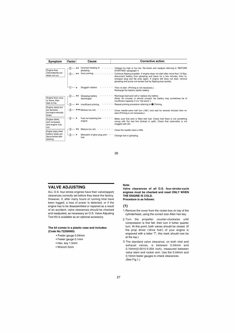
Symptom Factor Cause Corrective action
2
3
1
2
3
3
3
3
2
Voltage too high or too low. Re-check and readjust referring to "BEFORE STARTING" paragraph 4.Continue flipping propeller. If engine does not start after more than 10 flips, disconnect battery from glowplug and leave for a few minutes, then re-energize plug and flip prop again. If engine still does not start, remove glowplug and pump out excess fuel by flipping prop quickly.
Then re-start. (Priming is not necessary.)Recharge the electric starter battery.
Recharge lead-acid cell or replace dry battery.(Note: An unused, or almost unused, dry battery may sometimes be of insufficient capacity if it is "old stock".)
Repeat priming procedure referring to 7 Priming.
Close needle-valve half turn (180˚) and wait for several minutes then re-start.(Priming is not necessary.)
Make sure that tank is filled with fuel. Check that there is not something wrong with the fuel line (kinked or split). Check that carburettor is not clogged with dirt.
Close the needle-valve a little.
Change fuel or glowplug.
Incorrect heating of glowplug.Over priming.
Sluggish rotation.
Glowplug batterydischarged.
Insufficient priming.
Mixture too rich.
Fuel not reaching the engine.
Mixture too rich.
Mismatch of glow plug and fuel.
Engine firesintermittently butdoes not run.
Engine fires onceor twice, thenfails to fire.
Engine starts butrpm decreasesand engine eventuallystops.
Engine starts,rpm increasesand engine cuts out.
Engine stops whenbattery leads aredisconnected afterstarting.
. . . . .
. . . . . . . .
. . . . . .
. . . . . .
. . . . .
. . . . . . .
. . . . .
. . . . . . .
. . .
27
VALVE ADJUSTINGALL O.S. four-stroke engines have their valve(tappet) clearances correctly set before they leave the factory. However, if, after many hours of running time have been logged, a loss of power is detected, or if the engine has to be disassembled or repaired as a result of an accident, valve clearances should be checked and readjusted, as necessary an O.S. Valve Adjusting Tool Kit is available as an optional accessory.
• Feeler gauge 0.04mm
The kit comes in a plastic case and includes:(Code No.72200060)
• Feeler gauge 0.1mm• Hex. key 1.5mm• Wrench 5mm
Note:Valve clearances of all O.S. four-stroke-cycle engines must be checked and reset ONLY WHEN THE ENGINE IS COLD. Procedure is as follows:
Remove the cover from the rocker-box on top of the cylinderhead, using the correct size Allen hex key.
1.
Turn the propeller counter-clockwise until compression is first felt, then turn it futher quarter turn. At this point, both valves should be closed. (If the prop driver ('drive hub') of your engine is engraved with a letter 'T', this mark should now be at the top.)
2.
The standard valve clearance, on both inlet and exhaust valves, is between 0.04mm and 0.10mm(0.0015-0.004 inch), measured between valve stem and rocker arm. Use the 0.04mm and 0.10mm feeler gauges to check clearances.(See Fig.1.)
3.
(1)

28
Note:If the gap is found to be less than 0.04mm, it is not necessary to readjust the clearance if the engine has good compression and starts easily.
Equally, if the gap exceeds 0.10mm but is not more than 0.14mm (i.e. the thickness of both feeler gauges inserted together), it is not necessary to readjust the clearance if the engine runs satisfactorily.
Fig.1
0.04mmFeeler Gauge
Rocker Arm
Valve
If a clearance is found to be outside either of these limits, it should be reset as follows.
Carefully loosen the locknut on rocker-arm 1/4-1/2 turn with 5mm wrench. (Fig.2.)
1.
2.
Wrench
Loosen approx.1/4 to 1/2 turn.
Turn adjusting-screw approx. 1/2 turn counter-clockwise to open gap, using appropriate tool -i.e. Allen hex key.(Fig.3.)
Fig.2
Fig.3
AdjustingScrew
Turn approx.1/2 turn.
Allen Key
Locknut
(2)
29
3.
Fig.4
Insert 0.04mm feeler gauge between valve stem and rocker-arm and gently turn adjusting screw clockwise until it stops.(Fig.4.)
0.04mm FeelerGauge
Turn with fingersuntil it stops.
Re-tighten locknut while holding adjusting screw stationary. (Fig.5.)
4.
Hold at the screw head.
Fig.5Tighten Locknut.
Remove 0.04mm feeler, rotate prop through two revolutions and recheck gap.
5.
If clearance is correct, loosen the locknut on the other rocker-arm and repeat steps 1 to 5 above. Finally, replace rocker box cover.
6.
Remember:Excessive valve clearance will cause loss of power, due to valve (s) not opening sufficiently. On the other hand, a total loss of clearance may cause difficult starting due to valves not closing properly, resulting in loss of compression.

30
CARE AND MAINTENANCE To ensure that you obtain long life and peak performance from your engine, observe the following.
Avoid running the engine under dusty conditions. If necessary, lay a sheet of plywood or hard-board in front and under the nose of the model when starting the engine.
Foreign matter in the fuel can cause the carburetor jet to be partially clogged.
1.
2.
Therefore:rinse out the fuel tank with methanol or fuel before installing it.
Install a fuel filter in the fuel line between tank and carburettor.
Install a fuel filter in the outlet of your squeeze
bottle, or to the pump inlet if you use a manual or electric pump.
do not leave your fuel container open needlessly.
check filters periodically and clean them when necessary.
Do not leave raw fuel in the engine at the conclusion of a flying session: it may cause corrosion. The best practice is to disconnect the fuel line from the carburetor while the engine is running. Remaining fuel in the tank should also be drained off.
Clean the exterior of the engine with a clean cotton cloth.If this is not done, oil and dirt will burn onto the outside of the engine each time it is run and the engine will soon become discolored.
If the engine is not in use for a while (more than two months) remove the glowplug and rinse out the interior with kerosene (not gasoline), by rotating the crankshaft. Shake out residue, then inject light machine-oil through the plug hole and carburetor intake, again rotating the shaft to distribute the protective oil to all working parts.Gasoline, thinner, kerosene and light machine oil cause swelling and deterioration of plastic parts, "O" rings and fuel tubing. Use methanol for cleaning these engines.
Avoid unnecessary dismantling of your engine.
3.
4.
5.
6.
31
Radial Mount SetO.S.Glow Plug TYPE F
Propeller Locknut Set Valve Adjusting Tool Kit
Flexible Exhaust Pipes Super Filter (L)
NON-BUBBLE Weight Long Socket Wrench With Plug Grip
(71615009)
(71521000)
(72200080)
O.S. GENUINE PARTS & ACCESSORIES
For FS-30S (71908300)For FS-40S (71906000)
For FS-40S (45810100)(72200060)
NEEDLE VALVE EXTENSION SET (72403050)
(71531000)
1010A (72108300)1010B (72108310)
For FS-40S

32
( C.M
3x10
)
C.M
2.6x
12
C.M
2.6x
7C
.M2.
6x7
C.M
2.6x
18
2
23-2
33-
1
3-2
44-
14-
2
5
5-4
5-3 5-
2
5-1 6
78
9
110 11
1213
14
15
1617
16-1
18
1920
2122 23-1
23-2
23
24
2526
27
FS
-30S
EN
GIN
E E
XP
LO
DE
D V
IEW
Typ
e of
scr
ew
C...
Cap
Scr
ew M
...O
val F
illis
ter-
Hea
d S
crew
F...
Fla
t Hea
d S
crew
N...
Rou
nd H
ead
Scr
ew S
...S
et S
crew
33
Spe
cific
atio
ns a
re s
ubje
ct to
alte
ratio
n fo
r im
prov
emen
t with
out n
otic
e.
FS
-30S
PA
RT
S L
IST
No
.D
escr
ipti
on
Co
de
No
.S
crew
Set
Rock
er
Cove
rR
ock
er
Support
Ass
em
bly
R
ock
er
Support
R
ock
er
Arm
Reta
iner(2
pcs
.)R
ock
er
Arm
Ass
em
bly
(1pair)
R
ock
er
Arm
(1pc.
) T
appet A
dju
stin
g S
crew
Valv
e A
ssem
bly
(1pair)
In
take
Valv
e(1
pc.
) V
alv
e S
pring
(1pc.
) V
alv
e S
pring S
eat(
1pc.
) V
alv
e S
pring R
eta
iner(2
ps.
)C
ylin
der
Head(W
/Gask
et)
Cyl
inder
Head (
W/G
ask
et and V
alv
e A
ssem
bly
)C
arb
ure
tor
Com
ple
te (
20N
) G
ask
et S
et
Pis
ton R
ing
Pis
ton
Pis
ton P
inC
onnect
ing R
od
Cyl
inder
Lin
er
Cove
r P
late
Cra
nks
haft
C
ranks
haft S
pace
rC
ranks
haft B
all
Bearing
(Rear)
Cra
nkc
ase
Thru
st B
all(
2pc.
)C
am
shaft
Cam
Cove
rP
ush
Rod
(2pcs
.)P
ush
Rod C
ove
r A
ssem
bly
(2pcs
.) P
ush
Rod C
ove
r(1
pcs
.) P
ush
Rod C
ove
r “O
“Rin
g(2
pcs
.)C
am
Follo
wer(2
pcs
.)C
ranks
haft B
all
Bearing
(Fro
nt)
Drive
Hub
Lock
Nut S
et
F-2
010 S
ilence
r A
ssem
bly
S
ilence
r B
ody
P
ress
ure
Nip
ple
(N
o.5
) E
xhaust
Header
Pip
e A
ssem
bly
M
anifo
ld N
ut (M
9)
Glo
w P
lug T
ype F
1 2 3 3-1
3-2 4 4-1
4-2 5 5-1
5-2
5-3
5-4 6 7 8 9 10 11 12 13 14 15 16 16-1
17 18 19 20 21 22 23 23-1
23-2
24 25 26 27
4302
5100
4302
5000
4581
0100
4520
8010
4523
1000
4526
4000
2488
1824
4416
6110
4416
6100
4416
6000
4570
1100
4306
2000
4576
2100
4300
1000
2263
0002
4570
2100
4300
2000
4300
7000
4300
3100
4300
6000
4300
3200
4410
4030
4410
4100
4616
0400
4506
0309
4306
0200
4576
0110
4306
0000
4576
1200
4576
1100
4576
1000
4576
1600
4576
1410
4576
1400
4300
4200
4411
3000
4308
1000
2271
4100
4570
5000
4577
1000
4306
9000
7161
5009
4300
3400
4306
9200

34
FS
-40S
EN
GIN
E E
XP
LO
DE
D V
IEW
Typ
e of
scr
ew
C...
Cap
Scr
ew M
...O
val F
illis
ter-
Hea
d S
crew
F...
Fla
t Hea
d S
crew
N...
Rou
nd H
ead
Scr
ew S
...S
et S
crew
C.M
2.6X
7
C.M
3X18
C.M
3X8
C.M
2.6X
7
C.M
2.6X
12
2
33-
2
3-1
44-
14-
2
5-4
5-3
5-2
5
78
5-1
6
19
10
11 12 13
15 17
16
18
19
14
24
25
25-2
25-2
25-1
26
2021
2221
2327
2829
30
35
4522
5010
4522
5000
2321
0007
2320
9003
4520
8010
4523
1000
4526
4000
2488
1824
4526
6112
4526
6102
4526
6010
4520
1110
4526
2010
4523
1100
4520
1040
2263
0002
4520
2010
4577
1000
4520
7000
4528
4000
4520
3100
2335
6000
4520
3210
4520
4010
4520
4110
4506
0402
4506
0309
4506
0205
4526
0110
4526
0010
4576
1200
4526
1110
4526
1010
4576
1600
4526
1410
4526
1400
4520
4210
4521
3010
4528
1020
4521
4100
4520
5000
4522
6000
7161
5009
2420
3410
No
.D
escr
ipti
on
Co
de
No
.S
crew
Set
Rock
er
Cove
rR
ock
er
Support
Ass
em
bly
R
ock
er
Support
R
ock
er
Arm
Reta
iner(2
pcs
.)R
ock
er
Arm
Ass
em
bly
(1pair)
R
ock
er
Arm
(1pc.
) T
appet A
dju
stin
g S
crew
Valv
e A
ssem
bly
(1pair)
In
take
Valv
e(1
pc.
) V
alv
e S
pring
(1pc.
) V
alv
e S
pring S
eat(
1pc.
) V
alv
e S
pring R
eta
iner(2
ps.
)C
ylin
der
Head(W
/Gask
et)
Cyl
inder
Head (
W/G
ask
et and V
alv
e A
ssem
bly
)C
arb
ure
tor
Com
ple
te
Head G
ask
et
Pis
ton R
ing
Pis
ton
Pis
ton P
inC
onnect
ing R
od
Cyl
inder
Lin
er
Choke
Valv
e A
ssem
bly
Cove
r P
late
Bre
ath
er
Nip
ple
Cra
nks
haft
Cra
nks
haft B
all
Bearing
(Rear)
Cra
nkc
ase
Cam
shaft B
earing
Cam
shaft
Cam
Cove
rP
ush
Rod
(2pcs
.)P
ush
Rod C
ove
r A
ssem
bly
(2pcs
.) P
ush
Rod C
ove
r(1
pcs
.) P
ush
Rod C
ove
r “O
“Rin
g(2
pcs
.)C
am
Follo
wer(2
pcs
.)C
ranks
haft B
all
Bearing
(Fro
nt)
Drive
Hub
Pro
pelle
r W
ash
er
Pro
pelle
r N
ut
Sile
nce
r A
ssem
bly
S
ilence
r E
xhaust
Header
Pip
eG
low
Plu
g T
ype F
1 2 3 3-1
3-2 4 4-1
4-2 5 5-1
5-2
5-3
5-4 6 7 8 9 10 11 12 13 14 15 16 17 18 19 20 21 22 23 24 25 25-1
25-2
26 27 28 29 30
Spe
cific
atio
ns a
re s
ubje
ct to
alte
ratio
n fo
r im
prov
emen
t with
out n
otic
e.
FS
-40S
PA
RT
S L
IST

36
S.M3X3
N.+M3x6
M2.6X5
C.M2.6x7
1
1-1 2
4
53 6
6-2
7
6-46-3
6-1
TYPE 20N
CARBURETOR EXPLODED VIEW & PARTS LIST
Type of screw C...Cap Screw M...Oval Fillister-Head ScrewF...Flat Head Screw N...Round Head Screw S...Set Screw
Specifications are subject to alteration for improvement without notice.
Throttle Lever Assembly Throttle Lever Retaining ScrewCarburetor RotorCarburetor Body Carburetor Retaining Screw(3pcs.)Throttle Stop ScrewNeedle-valve Assembly Needle Nozzle Assembly Ratchet Spring Nozzle Retaining Screw(2pcs.)Air-bleed Screw
1
1-1
2
3
4
5
6
6-1
6-2
6-3
6-4
7
No. Code No. Description220814082208131345281200430811004528170022081811430819004578197043081960226113024528192022081820
37
TYPE FS-40S
N.+M3X6
C.M2.6X7
M2.6X5
S.M3X3
22081408220813134528112045281110452817002208181145281910457819702638150145283960230113084528192022081820
CARBURETTOR EXPLODED VIEW & PARTS LIST
Specifications are subject to alteration for improvement without notice.
Throttle Lever Assembly Throttle Lever Retaining ScrewCarburetor RotorCarburetor Body Carburetor Retaining Screw(3pcs.)Throttle Stop ScrewNeedle-valve Assembly Needle Set-screw Nozzle Assembly Ratchet Spring Nozzle Retaining Screw(2pcs.)Air-bleed Screw
Type of screw C...Cap Screw M...Oval Fillister-Head ScrewF...Flat Head Screw N...Round Head Screw S...Set Screw
1
1-1
2
4
5
3 6
7
6-5 6-3
6-4 6-1
6-2
11-123456
6-16-26-36-46-57
No. Code No. Description

38
14
UNF1/4-28
36
4- 3.3
71.5
15
37
4728
75
112
29
44
4.89 cc (0.299 cu.in.)19.5 mm (0.767 in.)16.4 mm (0.648 in.)2,500-13,000 r.p.m.0.5 ps / 0.51 ps / 10,000 r.p.m.279 g (9.56 oz.)
FS-30S THREE VIEW DRAWING Dimension(mm)
Specification
DisplacementBoreStrokePractical R.P.M.Power outputWeight
18 g (0.6 oz.)(Weight of Silencer)
39
6.49 cc (0.396 cu.in.)21.2 mm (0.835 in.)18.4 mm (0.724 in.)2,200-12,000 r.p.m.0.65 ps / 0.66 hp / 12,000 r.p.m.355 g (12.5 oz.)
FS-40S
FS-40S THREE VIEW DRAWING Dimension(mm)
DisplacementBoreStrokePractical R.P.M.Power outputWeight
Specification
(Weight of Silencer) 21.2 g (0.7 oz.)
3350
UNF1/4-28
24 5781 37
1781
.5
17.5
42
4- 3.7

40
MEMO
TEL. (06) 6702-0225FAX. (06) 6704-2722
6-15 3-Chome Imagawa Higashisumiyoshi-ku Osaka 546-0003, Japan
C Copyright 2002 by O.S.Engines Mfg. Co., Ltd. All rights reserved. Printed in Japan.
URL : http://www.os-engines.co.jp
UNEQ
UA
LLED QUALITY PRECISION & PERFORM
ANCE
ESTABLISHING THE STANDARDS OF EXCELLE
NCE
60090710 061105