Embed Size (px)
Citation preview
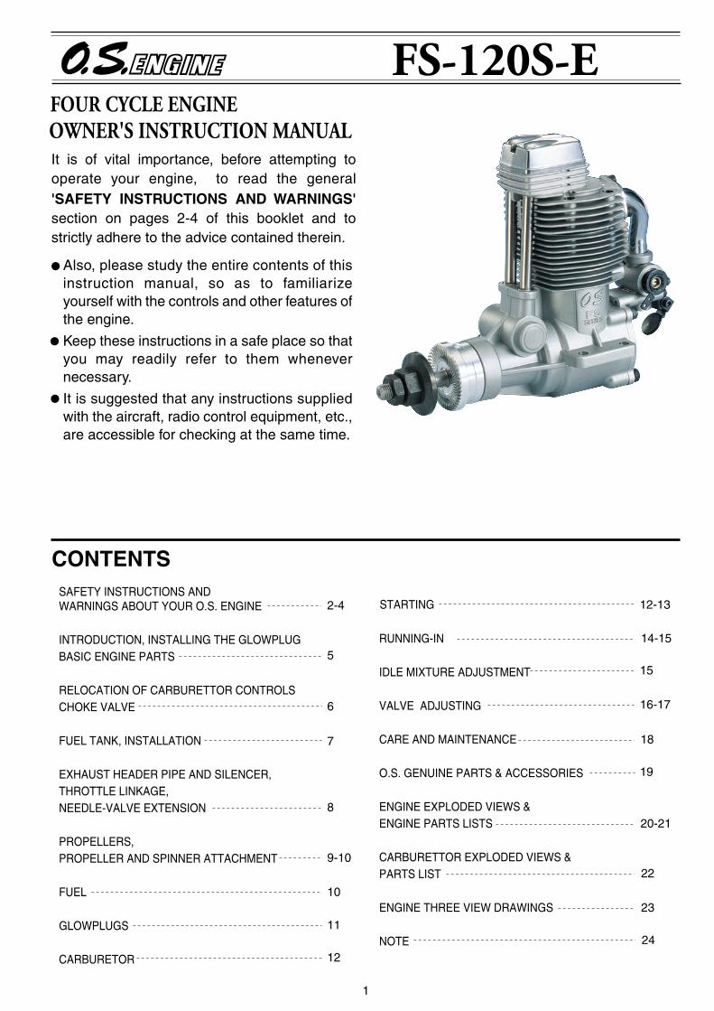
It is of vital importance, before attempting to operate your engine, to read the general 'SAFETY INSTRUCTIONS AND WARNINGS' section on pages 2-4 of this booklet and to strictly adhere to the advice contained therein.
Also, please study the entire contents of this instruction manual, so as to familiarize yourself with the controls and other features of the engine.
Keep these instructions in a safe place so that you may readily refer to them whenever necessary.
It is suggested that any instructions supplied with the aircraft, radio control equipment, etc., are accessible for checking at the same time.
1
14-15
SAFETY INSTRUCTIONS AND WARNINGS ABOUT YOUR O.S. ENGINE
INTRODUCTION, INSTALLING THE GLOWPLUGBASIC ENGINE PARTS
RELOCATION OF CARBURETTOR CONTROLSCHOKE VALVE
FUEL TANK, INSTALLATION
EXHAUST HEADER PIPE AND SILENCER,THROTTLE LINKAGE, NEEDLE-VALVE EXTENSION
PROPELLERS,PROPELLER AND SPINNER ATTACHMENT
FUEL
GLOWPLUGS
CARBURETOR
CONTENTS
RUNNING-IN
IDLE MIXTURE ADJUSTMENT
VALVE ADJUSTING
CARE AND MAINTENANCE
O.S. GENUINE PARTS & ACCESSORIES
ENGINE EXPLODED VIEWS &ENGINE PARTS LISTS
CARBURETTOR EXPLODED VIEWS &PARTS LIST
ENGINE THREE VIEW DRAWINGS
NOTE
STARTING 12-132-4
5
6
7
8
9-10
10
11
12
24
15
16-17
18
19
20-21
22
23
2
Remember that your engine is not a " toy ", but a highly efficient internal-combustion machine whose power is capable of harming you, or others, if it is misused or abused. As owner, you, alone, are responsible for the safe operation of your engine, so act with discretion and care at all times.If at some future date, your O.S. engine is acquired by another person, we would respectfully request that these instructions are also passed on to its new owner.
WARNINGSThese cover events which might involve serious ( in extreme circumstances, even fatal ) injury.
NOTESThese cover the many other possibilities, generally less obvious sources of danger, but which, under certain circumstances, may also cause damage or injury.
SAFETY INSTRUCTIONS AND WARNINGS ABOUT YOUR O.S. ENGINE
The advice which follows is grouped under two headings according to the degree of damage or danger which might arise through misuse or neglect.
WARNINGSNever touch, or allow any object to come into contact with, the rotating propeller and do not crouch over the engine when it is running.
A weakened or loose propeller may disintegrate or be thrown off and, since propeller tip speeds with powerful engines may exceed 600 feet(180 metres) per second, it will be understood that such a failure could result in serious injury, (see 'NOTES' section relating to propeller safety).
Model engine fuel is poisonous. Do not allow it to come into contact with the eyes or mouth. Always store it in a clearly marked container and out of the reach of children.
Model engine fuel is also highly flammable. Keep it away from an open flame, excessive heat, sources of sparks, or anything else which might ignite it. Do not smoke or allow anyone else to smoke, near to it.
Never operate your engine in an enclosed space. Model engines, like automobile engines, exhaust deadly carbon-monoxide. Run your engine only in an open area.
Model engines generate considerable heat. Do not touch any part of your engine until it has cooled. Contact with the muffler(silencer), cylinder head or exhaust header pipe, in particular, may result in a serious burn.
•
•
•
•
•
•
3
NOTESThis engine was designed for model aircraft. Do not attempt to use it for any other purpose.
Mount the engine in your model securely, following the manufacturers' recommendations, using appropriate screws and locknuts.
Be sure to use the silencer (muffler) supplied with the engine. Frequent exposure to an open exhaust may eventually impair your hearing. Such noise is also likely to cause annoyance to others over a wide area.
Install a top-quality propeller of the diameter and pitch specified for the engine and aircraft. Locate the propeller on the shaft so that the curved face of the blades faces forward-i.e. in the direction of flight. Firmly tighten the propeller nut, using the correct size wrench.
Always check the tightness of the propeller nut and retighten it, if necessary, before restarting the engine, particularly in the case of four-stroke-cycle engines. A safety locknut assembly is provided. Always use it. This will prevent the propeller from flying off in the event of a "backfire", even if it loosens.
If you install a spinner, make sure that it is a precision made product and that the slots for the propeller blades do not cut into the blade roots and weaken them.
Discard any propeller which has become split, cracked, nicked or otherwise rendered unsafe. Never attempt to repair such a propeller: destroy it. Do not modify a propeller in any way, unless you are highly experienced in tuning propellers for specialized competition work such as pylon-racing.
Use an electric starter for this engine. The wearing of safety glasses is also strongly recommended.
•
•
•
•
•
•
•
•
4
Take care that the glow plug clip or battery leads do not come into contact with the propeller. Also check the linkage to the throttle arm. A disconnected linkage could also foul the propeller.
After starting the engine, carry out any needle-valve readjustments from a safe position behind the rotating propeller. Stop the engine before attempting to make other adjustments to the carburettor.
Adjust the throttle linkage so that the engine stops when the throttle stick and trim lever on the transmitter are fully retarded. Alternatively, the engine may be stopped by cutting off the fuel supply. Never try to stop the engine physically.
Take care that loose clothing (ties, shirt sleeves, scarves, etc.) do not come into contact with the propeller. Do not carry loose objects (such as pencils, screwdrivers, etc.) in a shirt pocket from where they could fall through the propeller arc.
Do not start your engine in an area containing loose gravel or sand. The propeller may throw such material in your face and eyes and cause injury.
For their safety, keep all onlookers (especially small children) well back (at least 20 feet or 6 meters) when preparing your model for flight. If you have to carry the model to the take-off point with the engine running, be especially cautious. Keep the propeller pointed away from you and walk well clear of spectators.
Warning! Immediately after a glowplug-ignition engine has been run and is still warm, conditions sometimes exist whereby it is just possible for the engine to abruptly restart if the propeller is casually flipped over compression WITHOUT the glowplug battery being reconnected. Remember this if you wish to avoid the risk of a painfully rapped knuckle!
NOTES•
•
•
•
•
•
•
5
INTRODUCTION
INSTALLING THE GLOW PLUG
Glow plug
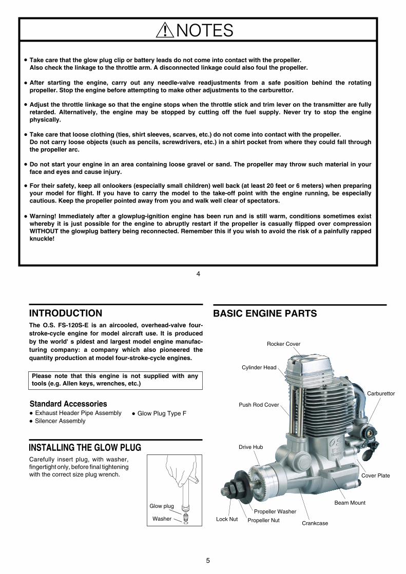
Carefully insert plug, with washer, fingertight only, before final tightening with the correct size plug wrench.
Washer
The O.S. FS-120S-E is an aircooled, overhead-valve four-stroke-cycle engine for model aircraft use. It is produced by the world' s pldest and largest model engine manufac-turing company: a company which also pioneered the quantity production at model four-stroke-cycle engines.
BASIC ENGINE PARTS
Rocker Cover
Cylinder Head
Push Rod Cover
Drive Hub
Propeller Washer
Propeller NutLock Nut
Carburettor
Cover Plate
Crankcase
Beam Mount
Standard AccessoriesExhaust Header Pipe Assembly Silencer Assembly
Glow Plug Type F
Please note that this engine is not supplied with any tools (e.g. Allen keys, wrenches, etc.)
6
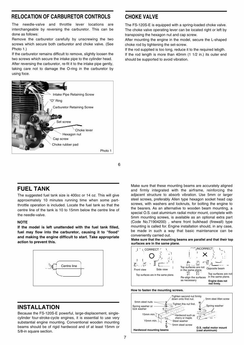
The needle-valve and throttle lever locations are interchangeable by reversing the carburetor. This can be done as follows:Remove the carburetor carefully by unscrewing the two screws which secure both carburetor and choke valve. (See Photo 1.)If the carburetor remains difficult to remove, slightly loosen the two screws which secure the intake pipe to the cylinder head.After reversing the carburetor, re-fit it to the intake pipe gently, taking care not to damage the O-ring in the carburetor by using foce.
RELOCATION OF CARBURETOR CONTROLS
Intake Pipe Retaining Screw
"O" Ring
Carburetor Retaining Screw
Choke lever
Set screw
Hexagon nutCap screw
Choke rubber pad
Photo 1
CHOKE VALVEThe FS-120S-E is equipped with a spring-loaded choke valve. The choke valve operating lever can be located right or left by transposing the hexagon nut and cap screw.After mounting the engine in the model, secure the L-shaped choke rod by tightening the set-screw.If the rod supplied is too long, reduce it to the required lebgth.If the rod length is more than 40mm (1 1/2 in.) its outer end should be supported to avoid vibration.
7
Because the FS-120S-E powerful, large-displacement, single-cylinder four-stroke-cycle engines, it is essential to use very substantial engine mounting. Conventional wooden mounting beams should be of rigid hardwood and of at least 15mm or 5/8-in square section.
INSTALLATION
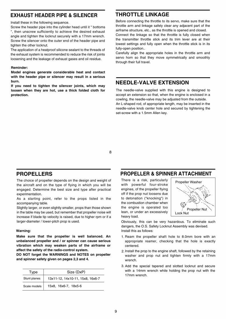
FUEL TANKThe suggested fuel tank size is 400cc or 14 oz. This will give approximately 10 minutes running time when some part-throttle operation is included. Locate the fuel tank so that the centre line of the tank is 10 to 15mm below the centre line of the needle-valve.
Make sure that the mounting beams are parallel and that their topsurfaces are in the same plane.
How to fasten the mounting screws.
Hardwood mounting beamsO.S. radial motor mount(cast aluminum)
Tighten second nut firmlydown onto first nut.
Tighten this nut first.
Steel washer
5mm steel nuts
5mm steel screw
Spring washer or lock washer
15mm min.
15mm min. Hardwood such as cherry or maple.
Spring washer
5mm steel Allen screw
Make sure that these mounting beams are accurately aligned and firmly integrated with the airframe, reinforcing the adjacent structure to absorb vibration. Use 5mm or larger steel screws, preferably Allen type hexagon socket head cap screws, with washers and locknuts, for bolting the engine to the bearers. As an alternative to wooden beam mounting, a special O.S. cast aluminium radial motor mount, complete with 5mm mounting screws, is available as an optional extra part (Code No.71904200) , where front bulkhead (firewall) type mounting is called for. Engine installation should, in any case, be made in such a way that basic maintenance can be conveniently carried out.
Front view
CORRECT
Side view
Top surfaces are in the same plane.Re-align the surfaces as necessary
INCORRECT
Top surfaces are not in the same plane.
Opposite beam
Top surfaces are not in the same plane.
Engine does not rest firmly.
NOTEIf the model is left unattended with the fuel tank filled, fuel may flow into the carburetor, causing it to "flood" and making the engine difficult to start. Take appropriate action to prevent this.
Centre line
8
NEEDLE-VALVE EXTENSIONThe needle-valve supplied with this engine is designed to accept an extension so that, when the engine is enclosed in a cowling, the needle-valve may be adjusted from the outside. An L-shaped rod, of appropriate length, may be inserted in the needle-valve knob center hole and secured by tightening the set-screw with a 1.5mm Allen key.
THROTTLE LINKAGEBefore connecting the throttle to its servo, make sure that the throttle arm and linkage safely clear any adjacent part of the airframe structure, etc., as the throttle is opened and closed.Connect the linkage so that the throttle is fully closed when the transmitter throttle stick and its trim lever are at their lowest settings and fully open when the throttle stick is in its fully-open position..Carefully align the appropriate holes in the throttle arm and servo horn so that they move symmetrically and smoothly through their full travel.
Install these in the following sequence.Screw the header pipe into the cylinder head until it " bottoms ", then unscrew sufficiently to achieve the desired exhaust angle and tighten the locknut securely with a 17mm wrench. Screw the silencer onto the outer end of the header pipe and tighten the other locknut.The application of a heatproof silicone sealant to the threads of the exhaust system is recommended to reduce the risk of joints loosening and the leakage of exhaust gases and oil residue.
EXHAUST HEADER PIPE & SILENCER
Reminder:Model engines generate considerable heat and contact with the header pipe or silencer may result in a serious burn. If you need to tighten the silencer joints, which may loosen when they are hot, use a thick folded cloth for protection.
9
The choice of propeller depends on the design and weight of the aircraft and on the type of flying in which you will be engaged. Determine the best size and type after practical experimentation. As a starting point, refer to the props listed in the accompanying table.Slightly larger, or even slightly smaller, props than those shown in the table may be used, but remember that propeller noise will increase if blade tip velocity is raised, due to higher rpm or if a larger-diameter / lower-pitch prop is used.
PROPELLERS
Type Size (DxP)
Stunt planes 13x11-12, 14x10-11, 15x8, 16x6-7
15x8, 16x6-7, 18x5-6Scale models
Make sure that the propeller is well balanced. An unbalanced propeller and / or spinner can cause serious vibration which may weaken parts of the airframe or affect the safety of the radio-control system.DO NOT forget the WARNINGS and NOTES on propeller and spinner safety given on pages 2,3 and 4.
Warning:
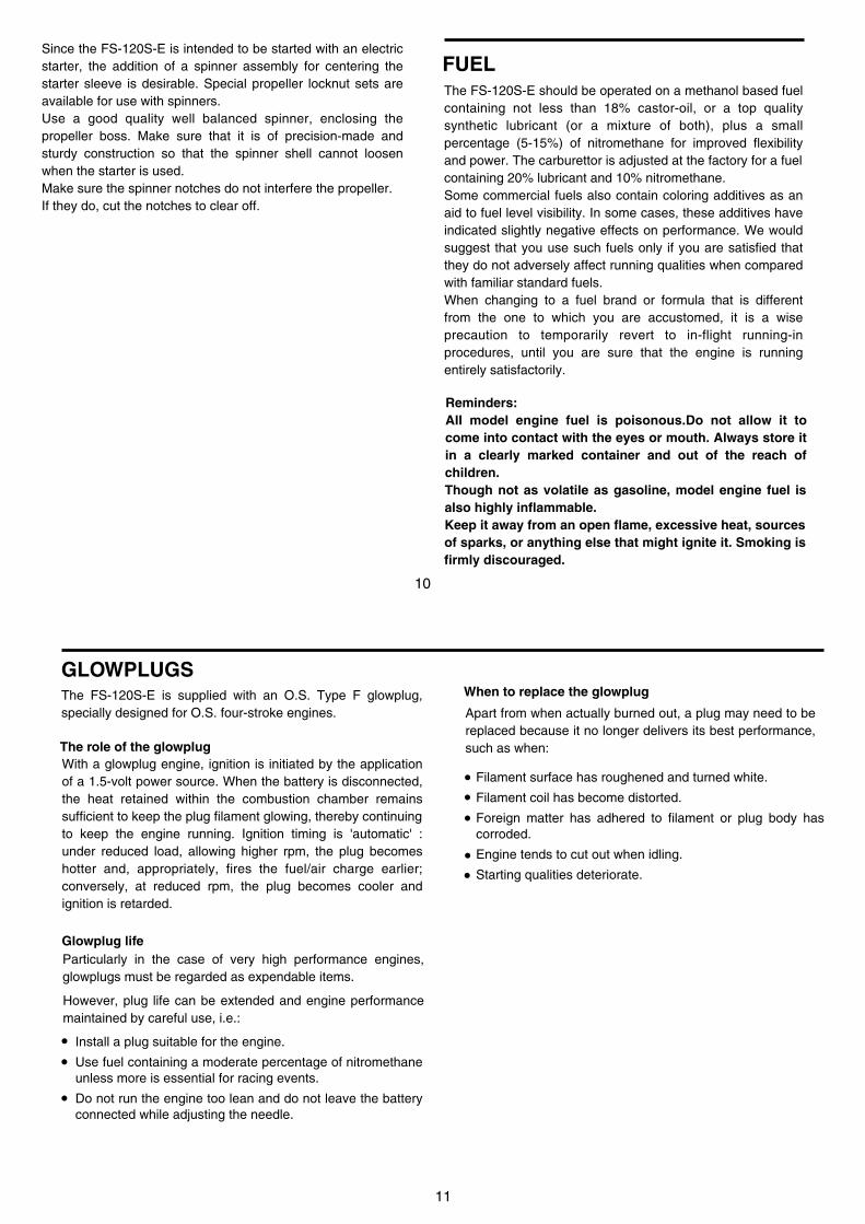
PROPELLER & SPINNER ATTACHMENT
Ream the propeller shaft hole to 8.0mm bore with an appropriate reamer, checking that the hole is exactly centered.
Install the prop to the engine shaft, followed by the retaining washer and prop nut and tighten firmly with a 17mm wrench.
There is a risk, particularly with powerful four-stroke engines, of the propeller flying off if the prop nut loosens due to detonation ("knocking") in the combustion chamber when the engine is operated too lean, or under an excessively heavy load.
Obviously, this can be very hazardous. To eliminate such dangers, the O.S. Safety Locknut Assembly was devised. Install this as follows:
Lock Nut
Propeller Washer
Propeller Nut
1.
2.
3. Add the special tapered and slotted locknut and secure with a 14mm wrench while holding the prop nut with the 17mm wrench.
10
FUELThe FS-120S-E should be operated on a methanol based fuel containing not less than 18% castor-oil, or a top quality synthetic lubricant (or a mixture of both), plus a small percentage (5-15%) of nitromethane for improved flexibility and power. The carburettor is adjusted at the factory for a fuel containing 20% lubricant and 10% nitromethane.Some commercial fuels also contain coloring additives as an aid to fuel level visibility. In some cases, these additives have indicated slightly negative effects on performance. We would suggest that you use such fuels only if you are satisfied that they do not adversely affect running qualities when compared with familiar standard fuels.When changing to a fuel brand or formula that is different from the one to which you are accustomed, it is a wise precaution to temporarily revert to in-flight running-in procedures, until you are sure that the engine is running entirely satisfactorily.
Reminders:AII model engine fuel is poisonous.Do not allow it to come into contact with the eyes or mouth. Always store it in a clearly marked container and out of the reach of children.Though not as volatile as gasoline, model engine fuel is also highly inflammable.Keep it away from an open flame, excessive heat, sources of sparks, or anything else that might ignite it. Smoking is firmly discouraged.
Since the FS-120S-E is intended to be started with an electric starter, the addition of a spinner assembly for centering the starter sleeve is desirable. Special propeller locknut sets are available for use with spinners.Use a good quality well balanced spinner, enclosing the propeller boss. Make sure that it is of precision-made and sturdy construction so that the spinner shell cannot loosen when the starter is used.Make sure the spinner notches do not interfere the propeller.If they do, cut the notches to clear off.
11
GLOWPLUGS
The role of the glowplug
Glowplug lifeParticularly in the case of very high performance engines, glowplugs must be regarded as expendable items.
Install a plug suitable for the engine.
Use fuel containing a moderate percentage of nitromethane unless more is essential for racing events.
Do not run the engine too lean and do not leave the battery connected while adjusting the needle.
However, plug life can be extended and engine performance maintained by careful use, i.e.:
With a glowplug engine, ignition is initiated by the application of a 1.5-volt power source. When the battery is disconnected, the heat retained within the combustion chamber remains sufficient to keep the plug filament glowing, thereby continuing to keep the engine running. Ignition timing is 'automatic' : under reduced load, allowing higher rpm, the plug becomes hotter and, appropriately, fires the fuel/air charge earlier; conversely, at reduced rpm, the plug becomes cooler and ignition is retarded.
Apart from when actually burned out, a plug may need to be replaced because it no longer delivers its best performance, such as when:
When to replace the glowplugThe FS-120S-E is supplied with an O.S. Type F glowplug, specially designed for O.S. four-stroke engines.
Filament surface has roughened and turned white.
Filament coil has become distorted.
Foreign matter has adhered to filament or plug body has corroded.
Engine tends to cut out when idling.
Starting qualities deteriorate.
••
•
•••
••
12
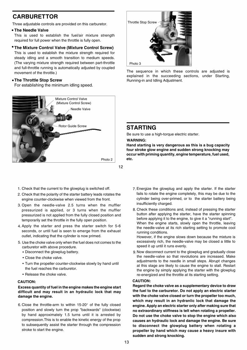
CARBURETTOR
The Needle ValveThis is used to establish the fuel/air mixture strength required for full power when the throttle is fully open.
The Mixture Control Valve (Mixture Control Screw)This is used to establish the mixture strength required for steady idling and a smooth transition to medium speeds. (The varying mixture strength required between part-throttle and full-throttle running is automatically adjusted by coupled movement of the throttle.)
The Throttle Stop ScrewFor establishing the minimum idling speed.
The sequence in which these controls are adjusted is explained in the succeeding sections, under Starting, Running-in and Idling Adjustment.
•
•
Three adjustable controls are provided on this carburetor.
•
Needle Valve
Mixture Control Valve (Mixture Control Screw)
Throttle Stop Screw
Rotor Guide Screw
Photo 2
Photo 3
STARTINGBe sure to use a high-torque electric starter.
Hand starting is very dangerous as this is a bug capacity four stroke glow engine and sudden strong knocking may occur with priming quantity, engine temperature, fuel used, etc.
WARNING:
13
Use the choke valve only when the fuel does not comes to the carburetor with above procedure.
Check that the current to the glowplug is switched off.
Check that the polarity of the starter battery leads rotates the engine counter-clockwise when viewed from the front.
Open the needle-valve 2.5 turns when the muffler pressurized is applied, or 3 turns when the muffler pressurized is not applied from the fully closed position and temporarily set the throttle in the fully open position.
Apply the starter and press the starter switch for 5-6 seconds, or until fuel is seen to emerge from the exhaust outlet, indicating that the cylinder is now primed.
Energize the glowplug and apply the starter. If the starter fails to rotate the engine completely, this may be due to the cylinder being over-primed, or to the starter battery being insufficiently charged.
1.
2.
3.
4.
5.
6.
Check these conditions and, instead of pressing the starter button after applying the starter, have the starter spinning before applying it to the engine, to give it a "running start".When the engine starts, slowly open the throttle, leaving the needle-valve at its rich starting setting to promote cool running conditions.However, if the engine slows down because the mixture is excessively rich, the needle-valve may be closed a little to speed it up until it runs evenly.
Now disconnect current to the glowplug and gradually close the needle-valve so that revolutions are increased. Make adjustments to the needle in small steps. Abrupt changes at this stage are likely to cause the engine to stall. Restart the engine by simply applying the starter with the glowplug re-energized and the throttle at its starting setting.
7.
8.
Disconnect the glowplug battery.
Close the choke valve.
Turn the propeller counter-clockwise slowly by hand untilthe fuel reaches the carburetor.
Release the choke valve.
CAUTION:
9.
Excess quantity of fuel in the engine makes the engine start difficult and may result in an hydraulic lock that may damage the engine.
Close the throttle-arm to within 15-20° of the fully closed position and slowly turn the prop "backwards" (clockwise) by hand approximately 1.5 turns until it is arrested by compression.This is to enable the kinetic energy of the prop to subsequently assist the starter through the compression stroke to start the engine.
CAUTION:Regard the choke valve as a supplementary device to draw the fuel to the carburetor. Do not apply an electric starter with the choke valve closed or turn the propeller too much, which may result in an hydranlic lock that damage the engine. Apply an electric starter only after making sure that no extraordinary stiffness is telt when rotating a propeller. Do not use the choke valve to stop the engine which also causes an hydraulic lock and damage the engine. Be sure to disconnect the glowplug battery when rotating a propeller by hand which may cause a heavy insure with sudden and strong knocking.
14
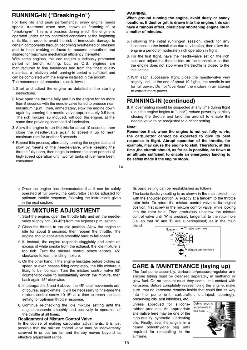
Start and adjust the engine as detailed in the starting instructions.
Now open the throttle fully and run the engine for no more than 5 seconds with the needle-valve tuned to produce near maximum r.p.m., then, immediately, slow the engine down again by opening the needle-valve approximately 0.5 turn. The rich mixture, so induced, will cool the engine, at the same time providing increased of lubrication.
Allow the engine to run like this for about 10 seconds, then close the needle-valve again to speed it up to near maximum rpm for another 5 seconds.
Repeat this process, alternately running the engine fast and slow by means of the needle-valve, while keeping the throttle fully open, then begin to extend the short periods of high-speed operation until two full tanks of fuel have been consumed.
Following the initial running-in session, check for any looseness in the installation due to vibration, then allow the engine a period of moderately rich operation in flight.
For the first flight, have the needle-valve set on the rich side and adjust the throttle trim on the transmitter so that the engine does not stop when the throttle is closed to the idle setting.
WARNING:When ground running the engine, avoid dusty or sandy locations. If dust or grit is drawn into the engine, this can have a ruinous effect, drastically shortening engine life in a matter of minutes.
RUNNING-IN (continued)
1.
2.
3.
4.
5.
6.
With each successive flight, close the needle-valve very slightly until, at the end of about 10 flights, the needle is set for full power. Do not "over-lean" the mixture in an attempt to extract more power.
If overheating should be suspected at any time during flight (i.e.if the engine begins to "labor") reduce power by partially closing the throttle and land the aircraft to enable the needle-valve to be readjusted to a richer setting.
7.
8.
Note:Remember that, when the engine is not yet fully run-in, the carburettor cannot be expected to give its best response in flight. Abrupt operation of the throttle, for example, may cause the engine to stall. Therefore, at this time ,the aircraft should, as far as is possible, be flown at an altitude sufficient to enable an emergency landing to be safely made if the engine stops.
RUNNING-IN ("Breaking-in")For long life and peak performance, every engine needs special treatment when new, known as "running-in" or "breaking-in". This is a process during which the engine is operated under strictly controlled conditions at the beginning of its life, in order to avoid the risk of immediate damage to certain components through becoming overheated or stressed and to help working surfaces to become smoothed and aligned for maximum mechanical efficiency thereafter.With some engines, this can require a tediously protracted period of bench running, but, as O.S. engines are manufactured to fine tolerances and from the finest quality materials, a relatively brief running-in period is sufficient and can be completed with the engine installed in the aircraft. The recommended procedure is as follows :
15
Start the engine, open the throttle fully and set the needle-valve slightly rich (30-45°) from the highest r.p.m. setting.
Close the throttle to the idle position. Allow the engine to idle for about 5 seconds, then reopen the throttle. The engine should accelerate smoothly back to full speed.
If, instead, the engine responds sluggishly and emits an excess of white smoke from the exhaust, the idle mixture is too rich. Turn the mixture control screw approx. 45° clockwise to lean the idling mixture.
On the other hand, if the engine hesitates before picking up speed or even ceases firing completely, the idle mixture is likely to be too lean. Turn the mixture control valve 90° counter-clockwise to substantially enrich the mixture, then back again 45° clockwise.
IDLE MIXTURE ADJUSTMENT
In paragraphs 3 and 4 above, the 45° total movements are, of course, approximate. It will be necessary to fine-tune the mixture control screw 10-15° at a time to reach the best setting for optimum throttle response.
Continue re-checking the idle mixture setting until the engine responds smoothly and positively to operation of the throttle at all times.
In the course of making carburetor adjustments, it is just possible that the mixture control valve may be inadvertently screwed in or out too far and thereby moved beyond its effective adjustment range.
Realignment of Mixture Control Valve
1.
2.
3.
4.
5.
6.
Once the engine has demonstrated that it can be safely operated at full power, the carburettor can be adjusted for optimum throttle response, following the instructions given in the next section.
9.The basic (factory) setting is as shown in the main sketch, i.e. with the shoulder portion 'A' exactly at a tangent to the throttle rotor hole. To return the mixture control valve to its original position, first screw in the mixture control valve, while looking into the rotor hole. Then graduakky unscrew the mixture control valve until 'A' is precisely tangential to the rotor hole (i.e. so that 'A' and 'B' are superimposed) as in the main sketch.
Its basic setting can be reestablished as follows:
Mixture control valve
Nozzle Throttle rotor hole
CARE & MAINTENANCE (laying up)The fuel pump assembly, carburettor/pressure-regulator and silicone tubing must be cleansed separately in methanol or glow fuel. On no account must they come into contact with kerosene. Before completely reassembling the engine, make sure that no kerosene remains inside that could find its way into the pump unit, carburettor, etc.Inject, sparingly, preserving oils, rust inhibitors, etc.
Debris tends toaccumulate inthis area
unless approved for silicone-rubber products. An appropriate alternative here may be one of the high-quality synthetic lubricating oils. Finally, seal the engine in a heavy polyethylene bag until required for reinstalling in the airframe.
16
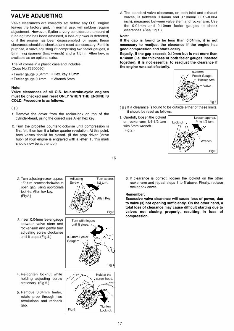
Note:Valve clearances of all O.S. four-stroke-cycle engines must be checked and reset ONLY WHEN THE ENGINE IS COLD. Procedure is as follows.
Remove the cover from the rocker-box on top of the cylinder-head, using the correct size Allen hex key.
1.
(Ⅰ)
Turn the propeller counter-clockwise until compression is first felt, then turn it a futher quarter revolution. At this point, both valves should be closed. (If the prop driver ('drive hub') of your engine is engraved with a letter 'T', this mark should now be at the top.)
2.
The standard valve clearance, on both inlet and exhaust valves, is between 0.04mm and 0.10mm(0.0015-0.004 inch), measured between valve stem and rocker arm. Use the 0.04mm and 0.10mm feeler gauges to check clearances. (See Fig.1.)
3.
Note:If the gap is found to be less than 0.04mm, it is not necessary to readjust the clearance if the engine has good compression and starts easily.Equally, if the gap exceeds 0.10mm but is not more than 0.14mm (i.e. the thickness of both feeler gauges inserted together), it is not essential to readjust the clearance if the engine runs satisfactorily.
Fig.1
(Ⅱ) If a clearance is found to be outside either of these limits, it should be reset as follows.
Carefully loosen the locknut on rocker-arm 1/4-1/2 turn with 5mm wrench.(Fig.2.)
1.Locknut
Wrench
Loosen approx.1/4 to 1/2 turn.
Fig.2
0.04mmFeeler Gauge
Rocker Arm
Valve
• Feeler gauge 0.04mm
Valve clearances are correctly set before any O.S. engine leaves the factory and, in normal use, will seldom require abjustment. However, if,after a very considerable amount of running time has been amassed, a loss of power is detected, or if the engine has been disassembled for repair, these clearances should be checked and reset as necessary. For this purpose, a valve adjusting kit comprising two feeler gauges, a 5mm ring spanner (box wrench) and a 1.5mm Allen key, is available as an optional extra.
VALVE ADJUSTING
The kit comes in a plastic case and includes:(Code No.72200060)
• Feeler gauge 0.1mm• Hex. key 1.5mm• Wrench 5mm
17
Re-tighten locknut while holding adjusting screw stationary. (Fig.5.)
4. Hold at thescrew head.
Fig.5Tighten Locknut.
Remove 0.04mm feeler, rotate prop through two revolutions and recheck gap.
5.
If clearance is correct, loosen the locknut on the other rocker-arm and repeat steps 1 to 5 above. Finally, replace rocker box cover.
6.
Remember:Excessive valve clearance will cause loss of power, due to valve (s) not opening sufficiently. On the other hand, a total loss of clearance may cause difficult starting due to valves not closing properly, resulting in loss of compression.
2.
3.
Turn adjusting-screw approx. 1/2 turn counter-clockwise to open gap, using appropriate tool -i.e. Allen hex key.(Fig.3.)
Fig.3
Fig.4
AdjustingScrew
Turn approx.1/2 turn.
Allen Key
Insert 0.04mm feeler gauge between valve stem and rocker-arm and gently turn adjusting screw clockwise until it stops.(Fig.4.) 0.04mm Feeler
Gauge
Turn with fingersuntil it stops.
18
CARE AND MAINTENANCETo ensure that you obtain long life and peak performance from your engine, observe the following.
Avoid running the engine under dusty conditions. If necessary, lay a sheet of plywood or hard-board in front and under the nose of the model when starting the engine.
Foreign matter in the fuel can cause the carburetor jet to be partially clogged.
1.
2.
Therefore:rinse out the fuel tank with methanol or fuel before installing it.
Install a fuel filter in the fuel line between tank and carburettor.
Install a fuel filter in the outlet of your squeeze bottle, or to the pump inlet if you use a manual or electric pump.
do not leave your fuel container open needlessly.
check filters periodically and clean them when necessary.
Clean the exterior of the engine with a clean cotton cloth.If this is not done, oil and dirt will burn onto the outside of the engine each time it is run and the engine will soon become discolored.
If the engine is not in use for a while (more than two months) remove the glowplug and rinse out the interior with kerosene (not gasoline), by rotating the crankshaft. Shake out residue, then inject light machine-oil through the plug hole and carburetor intake, again rotating the shaft to distribute the protective oil to all working parts.Gasoline, thinner, kerosene and light machine oil cause swelling and deterioration of plastic parts, "O" rings and fuel tubing. Use methanol for cleaning these engines.
Avoid unnecessary dismantling of your engine.
3.
4.
5.
6.
Do not leave raw fuel in the engine at the conclusion of a flying session: it may cause corrosion. The best practice is to disconnect the fuel line from the carburetor while the engine is running. Remaining fuel in the tank should also be drained off.
19
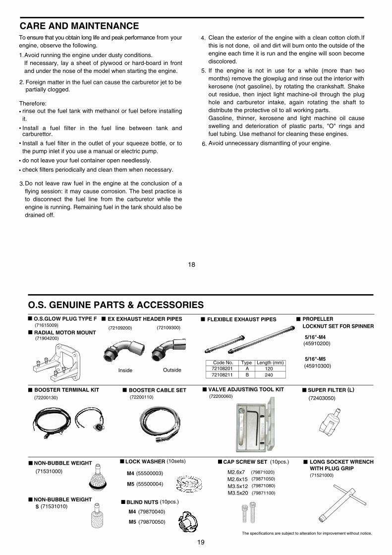
RADIAL MOTOR MOUNT
O.S.GLOW PLUG TYPE F EX EXHAUST HEADER PIPES FLEXIBLE EXHAUST PIPES
BOOSTER TERMINAL KIT BOOSTER CABLE SET
LONG SOCKET WRENCHWITH PLUG GRIP
Inside Outside
O.S. GENUINE PARTS & ACCESSORIES
(71904200)
(71615009)
(72200130) (72200110)
7210820172108211
AB
120240
(72109200) (72109300)
(71521000)
(72200060)
M2.6x7 (79871020)
M2.6x15 (79871050)
M3.5x12 (79871080)
M3.5x20 (79871100)
Code No. Type Length (mm)
VALVE ADJUSTING TOOL KIT
LOCK WASHER (10sets)
BLIND NUTS (10pcs.)
CAP SCREW SET (10pcs.)
(71531000)
(72403050)
(71531010)
NON-BUBBLE WEIGHT
SUPER FILTER (L)
The specifications are subject to alteration for improvement without notice.
NON-BUBBLE WEIGHTS
(79870040)
(55500003)
M4
M4
(79870050)M5
(55500004)M5
(45910300)
(45910200)
PROPELLER LOCKNUT SET FOR SPINNER
5/16"-M5
5/16"-M4

20
EX
PL
OD
ED
VIE
W
Typ
e of
scr
ew
C...
Cap
Scr
ew M
...O
val F
illis
ter-
Hea
d S
crew
F...
Fla
t Hea
d S
crew
N...
Rou
nd H
ead
Scr
ew S
...S
et S
crew
1
2
33-
2
3-1
44-
14-
2
5
5-4
5-3
5-2
8
5-1
6-4
6-3
6-2
6
6-1
79
10
11
12 13 14
15
16
17
21
27
28
28-2
28-1
28-2
29
18
19
20
2223
32-1
32
3331
30
2426
2524
C.M
3X8
C.M
4.0X
10
C.M
2.6X
15
C.M
3.5X
20
C.M
2.6X
7
(C.M
3.5X
12)
21
PARTS LIST
The specifications are subject to alteration for improvement without notice.
123
3-13-24
4-14-25
5-15-25-35-46
6-16-26-36-4789101112131415161718 45507010
4550310045505010290170044550601045503210455034004548400045581000455694204550402145504111455604104556031045560220455601404556004045560410455603104556021045560130455600304506120245561110455610104576160045561410455614014550421045513010
455660004550111045562010452311002268195345501020455140104553001045502040
455101004550820045508030455200002903100945564000455663104556611145566101
19202122232425262728
28-128-229303132
32-133
7161500945526400455263004552620045526100455260104552501145525001
DescriptionCode No.No.DescriptionCode No.No.Screw SetRocker CoverRocker Support Assembly Rocker Support Rocker Arm Retainer(2pcs.)Rocker Arm Assembly(1pair) Rocker Arm(1pc.) Tappet Adjusting ScrewIntake Valve Assembly(1pair) Intake Valve(1pc.) Valve Spring(1pc.) Valve Spring Retainer(1pc.) Split Cotter(2ps./1pair)Exhaust Valve Assembly(1pair) Exhaust Valve(1pc.) Valve Spring(1pc.) Valve Spring Retainer(1pc.) Split Cotter(2ps./1pair)Cylinder HeadCylinder Head (W/Gasket and Valve Assembly)Intake Pipe AssemblyCarburetor Complete Choke Valve AssemblyPiston RingPistonPiston PinPiston Pin RetainerConnecting RodCylinder LinerCover Plate
CrankshaftCrankshaft Ball Bearing(Rear)Gasket SetCrankcaseBreather NippleCamshaft Ball Bearing (1pcs.)CamshaftCam CoverPush Rod(2pcs.)Push Rod Cover Assembly(2pcs.) Push Rod Cover(1pcs.) Push Rod Cover "O" Ring(2pcs.)Cam Follower(2pcs.)Crankshaft Ball Bearing(Front)Thrust WasherDrive Hub Woodruff KeyLock Nut SetSilencer Assembly Silencer BodyExhaust Header Pipe Assembly Exhaust Header Pipe Exhaust Joint Exhaust Joint Nut Header Pipe NutGlow Plug Type F
22
The specifications are subject to alteration for improvement without notice.
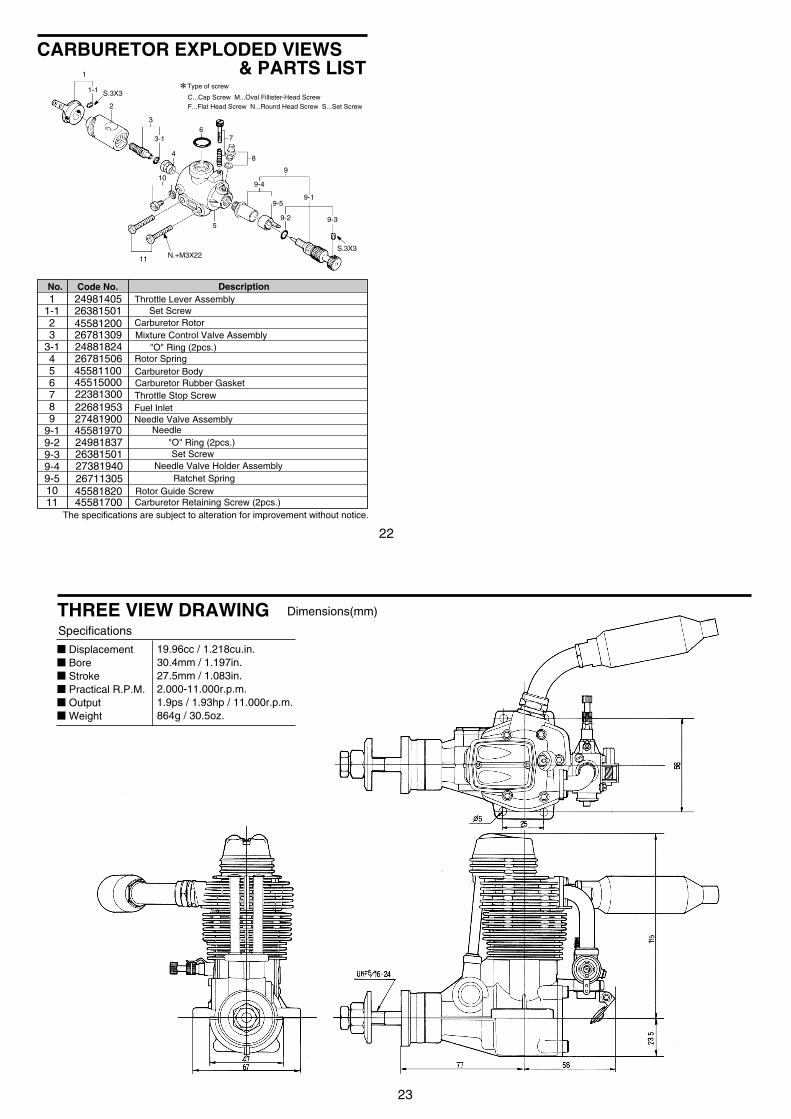
CARBURETOR EXPLODED VIEWS & PARTS LIST1
1-1
2
3
3-1
4
5
67
8
10
11
9
9-1
9-4
9-5
9-2 9-3
S.3X3N.+M3X22
S.3X3
4558170045581820267113052738194026381501249818374558197027481900226819532238130045515000455811002678150624881824267813094558120026381501249814051
1-123
3-1456789
9-19-29-39-49-51011
Type of screw
C...Cap Screw M...Oval Fillister-Head ScrewF...Flat Head Screw N...Round Head Screw S...Set Screw
DescriptionCode No.No.
Needle Valve AssemblyNeedle
"O" Ring (2pcs.)Set Screw
Needle Valve Holder AssemblyRatchet Spring
Carburetor Body
Rotor Guide Screw
Fuel Inlet
Mixture Control Valve Assembly
Carburetor Retaining Screw (2pcs.)
Throttle Lever AssemblySet Screw
Carburetor Rotor
"O" Ring (2pcs.)Rotor Spring
Carburetor Rubber GasketThrottle Stop Screw
23
Dimensions(mm)
Specifications
THREE VIEW DRAWING
DisplacementBoreStrokePractical R.P.M.OutputWeight
19.96cc / 1.218cu.in.30.4mm / 1.197in.27.5mm / 1.083in.2.000-11.000r.p.m.1.9ps / 1.93hp / 11.000r.p.m.864g / 30.5oz.

24
MEMO
C Copyright 2003 by O.S.Engines Mfg. Co., Ltd. All rights reserved. Printed in Japan.
TEL. (06) 6702-0225FAX. (06) 6704-2722
6-15 3-Chome Imagawa Higashisumiyoshi-ku Osaka 546-0003, Japan
URL : http://www.os-engines.co.jp
UNEQ
UA
LLED QUALITY PRECISION & PERFORM
ANCE
ESTABLISHING THE STANDARDS OF EXCELLE
NCE
60090510 061103