Embed Size (px)
Citation preview
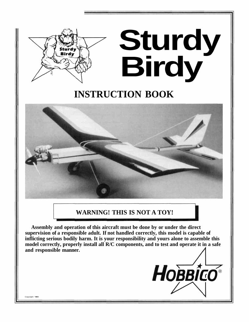
SturdyBirdy
INSTRUCTION BOOK
WARNING! THIS IS NOT A TOY!
Assembly and operation of this aircraft must be done by or under the directsupervision of a responsible adult. If not handled correctly, this model is capable ofinflicting serious bodily harm. It is your responsibility and yours alone to assemble thismodel correctly, properly install all R/C components, and to test and operate it in a safeand responsible manner.
Copyright 1994
Table of ContentsIntroduction............................................................................................................2Parts List...............................................................................................................3Additional Item Description................................................................................4Additional Item List.............................................................................................4Tools or Supplies Needed.....................................................................................5Fin/Rudder Construction....................................................................................5Stabilizer / Elevator Construction ........................................................................7Wing Assembly ....................................................................................................8Covering..................................................................................................................9Installing the Hinges ............................................................................................9Attaching the Control Horns ..............................................................................10Fuselage Construction........................................................................................10Final Assembly...................................................................................................16Balancing..............................................................................................................17Getting Ready for Flying ...................................................................................17Flying .................................................................................................................17Repairing.............................................................................................................18
INTRODUCTIONCongratulations on your purchase of the HOBBICO STURDY BIRDY, THE FIRST REAL SUPER TRAINER You
now own the BEST FLYING durable trainer available By following these instructions as you assemble the model youwill have a great flying plane that will not only teach you how to fly but it will stick with you while you learn, no matterhow long it may take!
The first thing you should do after reading this paragraph is check the parts in this kit against the parts list on the nextpage to make sure everything is here
We strongly recommend that you join AMA, The Academy of Model Aeronautics Being an AMA member entitles youto liability insurance, puts you in touch with your local flying club and includes a subscription to MODEL AVIATIONmagazine which has a monthly listing of all "goings on" in model aviation
The insurance is the most important advantage of the AMA membership because if your model hits someone orsomething you are liable for any damage it causes.
The address for the AMA is.Academy of Model Aeronautics
5151 East Memorial DriveMuncie, IN 47302(800) 435-9262
We also recommend that you join your local flying club There you will find people who can help you learn to fly andteach you the safe ways of handling your aircraft.
2
PARTS LIST
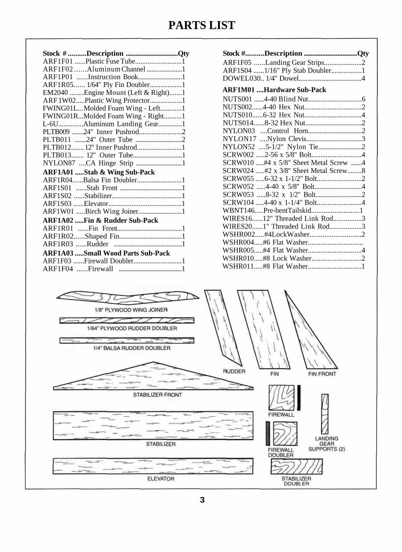
Stock # ..........Description ................................QtyARF1F01 ......Plastic Fuse Tube..........................1ARF1F02 ......Aluminum Channel ......................1ARF1P01 ......Instruction Book...........................1ARF1R05...... 1/64" Ply Fin Doubler..................1EM2040 ........Engine Mount (Left & Right).......1ARF 1W02.....Plastic Wing Protector..................1FWING01L... Molded Foam Wing - Left............1FWING01R...Molded Foam Wing - Right..........1L-6U..............Aluminum Landing Gear..............1PLTB009 .......24" Inner Pushrod........................2PLTB011 .......24" Outer Tube .............................2PLTB012....... 12" Inner Pushrod.........................1PLTB013....... 12" Outer Tube.............................1NYLON87 ....CA Hinge Strip .............................1ARF1A01 .....Stab & Wing Sub-PackARF1R04......Balsa Fin Doubler.........................1ARF1S01 ......Stab Front .....................................1ARF1S02 ......Stabilizer.......................................1ARF1S03 ......Elevator.........................................1ARF1W01 .....Birch Wing Joiner..........................1ARF1A02 .....Fin & Rudder Sub-PackARF1R01 ......Fin Front.......................................1ARF1R02......Shaped Fin....................................1ARF1R03 ......Rudder .........................................1ARF1A03 .....Small Wood Parts Sub-PackARF1F03 ......Firewall Doubler...........................1ARF1F04 ......Firewall ........................................1
Stock #..........Description ................................QtyARF1F05 ......Landing Gear Strips.....................2ARF1S04 ......1/16" Ply Stab Doubler.................1DOWEL030.. 1/4" Dowel....................................4ARF1M01 ....Hardware Sub-PackNUTS001 ......4-40 Blind Nut..............................6NUTS002......4-40 Hex Nut................................2NUTS010......6-32 Hex Nut................................4NUTS014......8-32 Hex Nut................................2NYLON03 ....Control Horn.................................2NYLON17 ....Nylon Clevis.................................3NYLON52 ....5-1/2" Nylon Tie...........................2SCRW002 .....2-56 x 5/8" Bolt............................4SCRW010 .....#4 x 5/8" Sheet Metal Screw .......4SCRW024 .....#2 x 3/8" Sheet Metal Screw........8SCRW055 .....6-32 x 1-1/2" Bolt.........................2SCRW052 .....4-40 x 5/8" Bolt............................4SCRW053 .....8-32 x 1/2" Bolt............................2SCRW104 .....4-40 x 1-1/4" Bolt.........................4WBNT146.....Pre-bentTailskid...........................1WIRES16......12" Threaded Link Rod................3WIRES20......1" Threaded Link Rod..................3WSHR002.....#4LockWasher............................2WSHR004.....#6 Flat Washer...............................WSHR005.....#4 Flat Washer..............................4WSHR010.....#8 Lock Washer............................2WSHR011.....#8 Flat Washer..............................1
3
ADDITIONAL ITEMSNEEDED
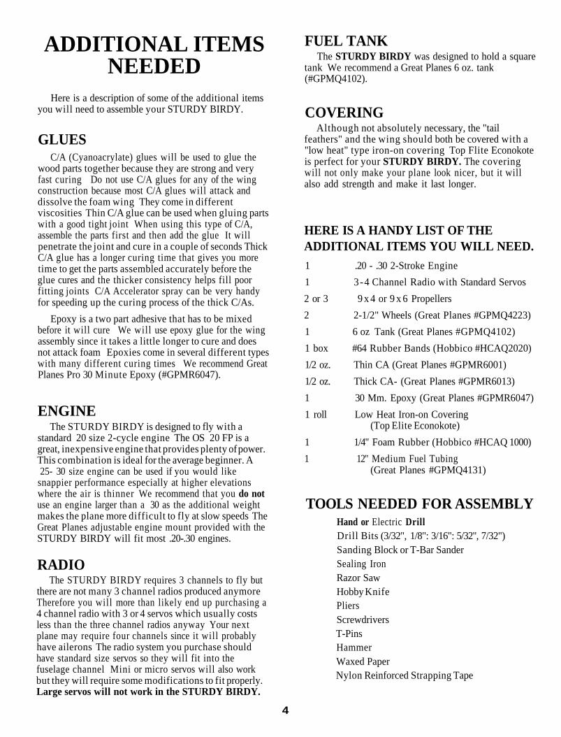
Here is a description of some of the additional itemsyou will need to assemble your STURDY BIRDY.
GLUESC/A (Cyanoacrylate) glues will be used to glue the
wood parts together because they are strong and veryfast curing Do not use C/A glues for any of the wingconstruction because most C/A glues will attack anddissolve the foam wing They come in differentviscosities Thin C/A glue can be used when gluing partswith a good tight joint When using this type of C/A,assemble the parts first and then add the glue It willpenetrate the joint and cure in a couple of seconds ThickC/A glue has a longer curing time that gives you moretime to get the parts assembled accurately before theglue cures and the thicker consistency helps fill poorfitting joints C/A Accelerator spray can be very handyfor speeding up the curing process of the thick C/As.
Epoxy is a two part adhesive that has to be mixedbefore it will cure We will use epoxy glue for the wingassembly since it takes a little longer to cure and doesnot attack foam Epoxies come in several different typeswith many different curing times We recommend GreatPlanes Pro 30 Minute Epoxy (#GPMR6047).
ENGINEThe STURDY BIRDY is designed to fly with a
standard 20 size 2-cycle engine The OS 20 FP is agreat, inexpensive engine that provides plenty of power.This combination is ideal for the average beginner. A25- 30 size engine can be used if you would like
snappier performance especially at higher elevationswhere the air is thinner We recommend that you do notuse an engine larger than a 30 as the additional weightmakes the plane more difficult to fly at slow speeds TheGreat Planes adjustable engine mount provided with theSTURDY BIRDY will fit most .20-.30 engines.
RADIOThe STURDY BIRDY requires 3 channels to fly but
there are not many 3 channel radios produced anymoreTherefore you will more than likely end up purchasing a4 channel radio with 3 or 4 servos which usually costsless than the three channel radios anyway Your nextplane may require four channels since it will probablyhave ailerons The radio system you purchase shouldhave standard size servos so they will fit into thefuselage channel Mini or micro servos will also workbut they will require some modifications to fit properly.Large servos will not work in the STURDY BIRDY.
FUEL TANKThe STURDY BIRDY was designed to hold a square
tank We recommend a Great Planes 6 oz. tank(#GPMQ4102).
COVERINGAlthough not absolutely necessary, the "tail
feathers" and the wing should both be covered with a"low heat" type iron-on covering Top Flite Econokoteis perfect for your STURDY BIRDY. The coveringwill not only make your plane look nicer, but it willalso add strength and make it last longer.
HERE IS A HANDY LIST OF THEADDITIONAL ITEMS YOU WILL NEED.1 .20 - .30 2-Stroke Engine1 3-4 Channel Radio with Standard Servos2 or 3 9 x 4 or 9 x 6 Propellers2 2-1/2" Wheels (Great Planes #GPMQ4223)1 6 oz Tank (Great Planes #GPMQ4102)1 box #64 Rubber Bands (Hobbico #HCAQ2020)1/2 oz. Thin CA (Great Planes #GPMR6001)1/2 oz. Thick CA- (Great Planes #GPMR6013)1 30 Mm. Epoxy (Great Planes #GPMR6047)1 roll Low Heat Iron-on Covering
(Top Elite Econokote)1 1/4" Foam Rubber (Hobbico #HCAQ 1000)1 12" Medium Fuel Tubing
(Great Planes #GPMQ4131)
TOOLS NEEDED FOR ASSEMBLYHand or Electric DrillDrill Bits (3/32", 1/8": 3/16": 5/32", 7/32")Sanding Block or T-Bar SanderSealing IronRazor SawHobby KnifePliersScrewdriversT-PinsHammerWaxed PaperNylon Reinforced Strapping Tape
4
CONSTRUCTIONFIN/RUDDER
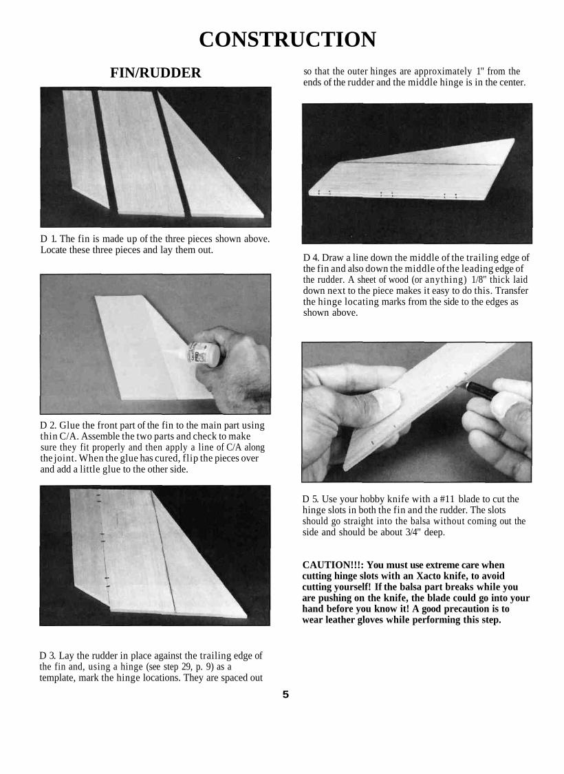
D 1. The fin is made up of the three pieces shown above.Locate these three pieces and lay them out.
D 2. Glue the front part of the fin to the main part usingthin C/A. Assemble the two parts and check to makesure they fit properly and then apply a line of C/A alongthe joint. When the glue has cured, flip the pieces overand add a little glue to the other side.
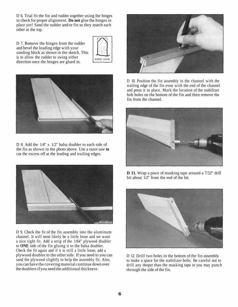
so that the outer hinges are approximately 1" from theends of the rudder and the middle hinge is in the center.
D 4. Draw a line down the middle of the trailing edge ofthe fin and also down the middle of the leading edge ofthe rudder. A sheet of wood (or anything) 1/8" thick laiddown next to the piece makes it easy to do this. Transferthe hinge locating marks from the side to the edges asshown above.
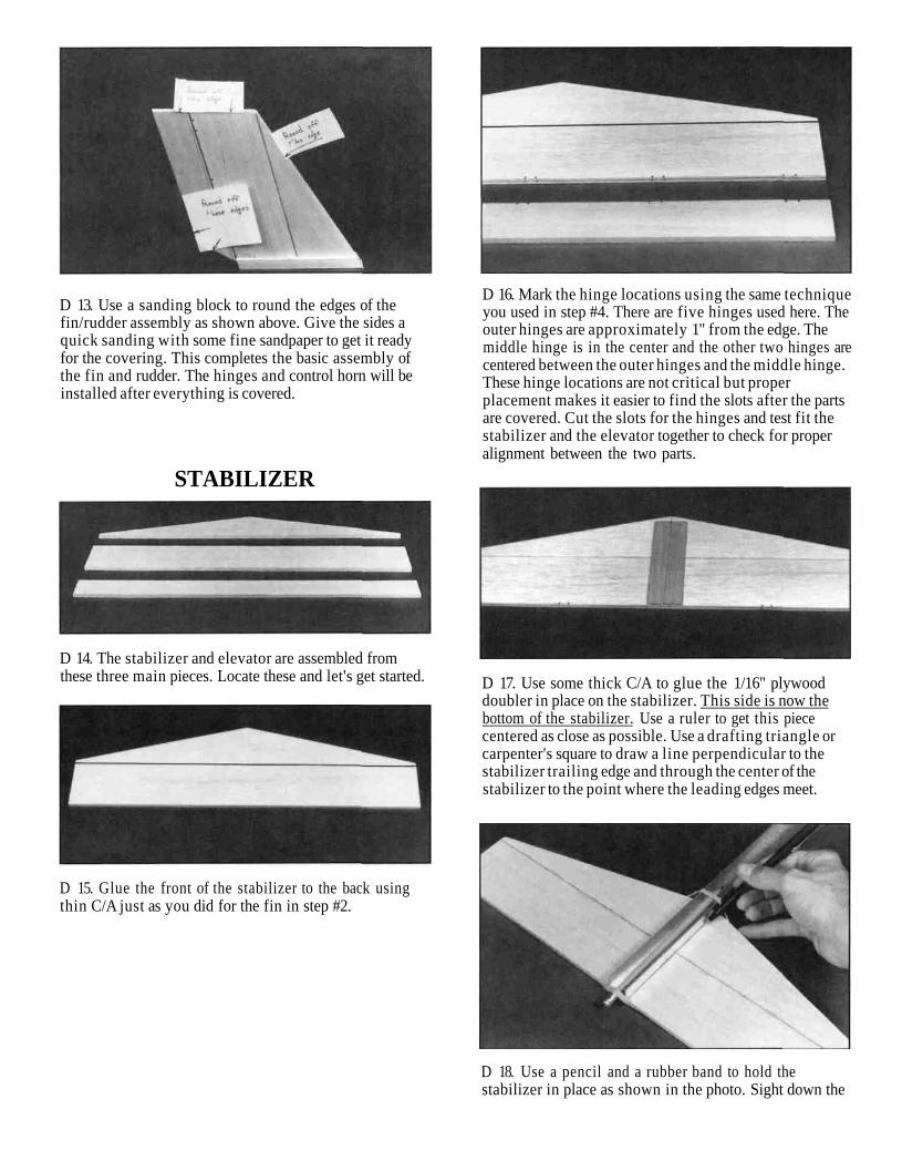
D 5. Use your hobby knife with a #11 blade to cut thehinge slots in both the fin and the rudder. The slotsshould go straight into the balsa without coming out theside and should be about 3/4" deep.
CAUTION!!!: You must use extreme care whencutting hinge slots with an Xacto knife, to avoidcutting yourself! If the balsa part breaks while youare pushing on the knife, the blade could go into yourhand before you know it! A good precaution is towear leather gloves while performing this step.
D 3. Lay the rudder in place against the trailing edge ofthe fin and, using a hinge (see step 29, p. 9) as atemplate, mark the hinge locations. They are spaced out
5
D 6. Trial fit the fin and rudder together using the hingesto check for proper alignment. Do not glue the hinges inplace yet! Sand the rudder and/or fin so they match eachother at the top.
D 7. Remove the hinges from the rudderand bevel the leading edge with yoursanding block as shown in the sketch. Thisis to allow the rudder to swing eitherdirection once the hinges are glued in.
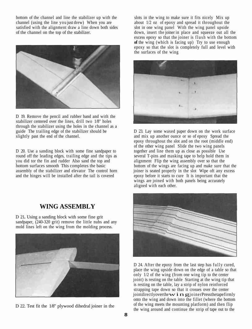
D 8. Add the 1/4" x 1/2" balsa doubler to each side ofthe fin as shown in the photo above. Use a razor saw tocut the excess off at the leading and trailing edges.
D 9. Check the fit of the fin assembly into the aluminumchannel. It will most likely be a little loose and we wanta nice tight fit. Add a strip of the 1/64" plywood doublerto ONE side of the fin gluing it to the balsa doubler.Check the fit again and if it is still a little loose, add aplywood doubler to the other side. If you need to you cansand the plywood slightly to help the assembly fit. Also,you can have the covering material continue down overthe doublers if you need the additional thickness.
D 10. Position the fin assembly in the channel with thetrailing edge of the fin even with the end of the channeland press it in place. Mark the location of the stabilizerbolt holes on the bottom of the fin and then remove thefin from the channel.
D 11. Wrap a piece of masking tape around a 7/32" drillbit about 1/2" from the end of the bit.
D 12. Drill two holes in the bottom of the fin assemblyto make a space for the stabilizer bolts. Be careful not todrill any deeper than the masking tape or you may punchthrough the side of the fin.
6
D 13. Use a sanding block to round the edges of thefin/rudder assembly as shown above. Give the sides aquick sanding with some fine sandpaper to get it readyfor the covering. This completes the basic assembly ofthe fin and rudder. The hinges and control horn will beinstalled after everything is covered.
D 16. Mark the hinge locations using the same techniqueyou used in step #4. There are five hinges used here. Theouter hinges are approximately 1" from the edge. Themiddle hinge is in the center and the other two hinges arecentered between the outer hinges and the middle hinge.These hinge locations are not critical but properplacement makes it easier to find the slots after the partsare covered. Cut the slots for the hinges and test fit thestabilizer and the elevator together to check for properalignment between the two parts.
STABILIZER
D 14. The stabilizer and elevator are assembled fromthese three main pieces. Locate these and let's get started.
D 15. Glue the front of the stabilizer to the back usingthin C/A just as you did for the fin in step #2.
D 17. Use some thick C/A to glue the 1/16" plywooddoubler in place on the stabilizer. This side is now thebottom of the stabilizer. Use a ruler to get this piececentered as close as possible. Use a drafting triangle orcarpenter's square to draw a line perpendicular to thestabilizer trailing edge and through the center of thestabilizer to the point where the leading edges meet.
D 18. Use a pencil and a rubber band to hold thestabilizer in place as shown in the photo. Sight down the
bottom of the channel and line the stabilizer up with thechannel (using the line you just drew) When you aresatisfied with the alignment draw a line down both sidesof the channel on the top of the stabilizer.
D 19. Remove the pencil and rubber band and with thestabilizer centered over the lines, drill two 1/8" holesthrough the stabilizer using the holes in the channel as aguide The trailing edge of the stabilizer should beslightly past the end of the channel.
D 20. Use a sanding block with some fine sandpaper toround off the leading edges, trailing edge and the tips asyou did tor the fin and rudder Also sand the top andbottom surfaces smooth This completes the basicassembly of the stabilizer and elevator The control hornand the hinges will be installed after the tail is covered
slots in the wing to make sure it fits nicely Mix upabout 1/2 oz of epoxy and spread it throughout theslot in one wing panel With the wing panel upsidedown, insert the joiner in place and squeeze out all theexcess epoxy so that the joiner is f l u s h with the bottomof the wing (which is facing up) Try to use enoughepoxy so that the slot is completely full and level withthe surfaces of the wing
D 23. Lay some waxed paper down on the work surfaceand mix up another ounce or so of epoxy Spread theepoxy throughout the slot and on the root (middle end)of the other wing panel Slide the two wing panelstogether and line them up as close as possible Useseveral T-pins and masking tape to help hold them inalignment Flip the wing assembly over so that thebottom of the wings are facing up and make sure that thejoiner is seated properly in the slot Wipe oft any excessepoxy before it starts to cure It is important that thewings are joined with both panels being accuratelyaligned with each other.
WING ASSEMBLYD 21. Using a sanding block with some fine gritsandpaper, (240-320 grit) remove the little nubs and anymold lines left on the wing from the molding process.
D 22. Test fit the 1/8" plywood dihedral joiner in the
D 24. After the epoxy from the last step has fu l l y cured,place the wing upside down on the edge of a table so thatonly 1/2 of the wing (from one wing tip to the centerjoint) is resting on the table Starting at the wing tip thatis resting on the table, lay a strip of nylon reinforcedstrapping tape down so that it crosses over the centerjoint directly over the wing joiner Press the tape firmlyonto the wing and down into the fillet (where the bottomof the wing meets the mounting platform) and then flipthe wing around and continue the strip of tape out to the
8
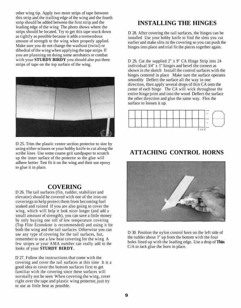
other wing tip. Apply two more strips of tape betweenthis strip and the trailing edge of the wing and the fourthstrip should be added between the first strip and theleading edge of the wing The photo shows where thestrips should be located. Try to get this tape stuck downas tightly as possible because it adds a tremendousamount of strength to the wing when properly applied.Make sure you do not change the washout (twist) ordihedral of the wing when applying the tape strips Ifyou are planning on doing some aerobatics or combatwith your STURDY BIRDY you should also put threestrips of tape on the top surface of the wing.
INSTALLING THE HINGESD 28. After covering the tail surfaces, the hinges can beinstalled Use your hobby knife to find the slots you cutearlier and make slits in the covering so you can push thehinges into place and trial fit the pieces together again.
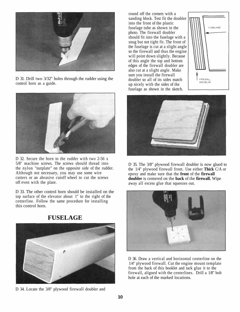
D 29. Cut the supplied 2" x 9" CA Hinge Strip into 24individual 3/4" x 1" hinges and bevel the corners asshown in the sketch Install the control surfaces with thehinges centered in place Make sure the surface operatessmoothly Deflect the surface all the way in onedirection, then apply several drops of thin CA onto thecenter of each hinge The CA will wick throughout theentire hinge joint and into the wood Deflect the surfacethe other direction and glue the same way. Flex thesurface to loosen it up.
D 25. Trim the plastic center section protector to size byusing either scissors or your hobby knife to cut along thescribe lines Use some coarse grit sandpaper to scratchup the inner surface of the protector so the glue willadhere better Test fit it on the wing and then use epoxyto glue it in place.
COVERINGD 26. The tail surfaces (fin, rudder, stabilizer andelevator) should be covered with one of the iron-oncoverings to help protect them from becoming fuelsoaked and ruined If you are also going to cover thewing, which will help it look nicer longer (and add asmall amount of strength), you can save a little moneyby only buying one roll of low temperature covering(Top Flite Econokote is recommended) and using it forboth the wing and the tail surfaces Otherwise you canuse any type of covering for the tail surfaces, but,remember to use a low heat covering for the wing Afew stripes or your AMA number can really add to thelooks of your STURDY BIRDY.
D 27. Follow the instructions that come with thecovering and cover the tail surfaces at this time It is agood idea to cover the bottom surfaces first to getfamiliar with the covering since these surfaces willnormally not be seen When covering the wing, coverright over the tape and plastic wing protector, just tryto use as little heat as possible.
ATTACHING CONTROL HORNS
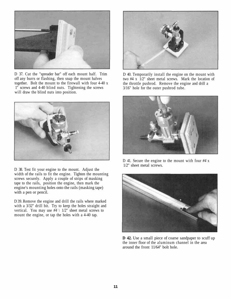
D 30. Position the nylon control horn on the left side ofthe rudder about 1" up from the bottom with the fourholes lined up with the leading edge. Use a drop of ThinC/A to tack glue the horn in place.
9
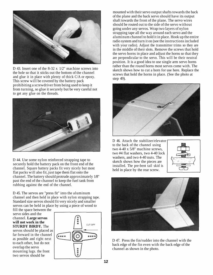
D 31. Drill two 3/32" holes through the rudder using thecontrol horn as a guide.
round off the corners with asanding block. Test fit the doublerinto the front of the plasticfuselage tube as shown in thephoto. The firewall doublershould fit into the fuselage with asnug but not tight fit. The front ofthe fuselage is cut at a slight angleso the firewall and thus the enginewill point down slightly. Becauseof this angle the top and bottomedges of the firewall doubler arealso cut at a slight angle. Makesure you install the firewalldoubler so all of its sides matchup nicely with the sides of thefuselage as shown in the sketch.
D 32. Secure the horn to the rudder with two 2-56 x5/8" machine screws. The screws should thread intothe nylon "nutplate" on the opposite side of the rudder.Although not necessary, you may use some wirecutters or an abrasive cutoff wheel to cut the screwsoff even with the plate.
D 33. The other control horn should be installed on thetop surface of the elevator about 1" to the right of thecenterline. Follow the same procedure for installingthis control horn.
FUSELAGE
D 35. The 3/8" plywood firewall doubler is now glued tothe 1/4" plywood firewall front. Use either Thick C/A orepoxy and make sure that the front of the firewalldoubler is centered on the back of the firewall. Wipeaway all excess glue that squeezes out.
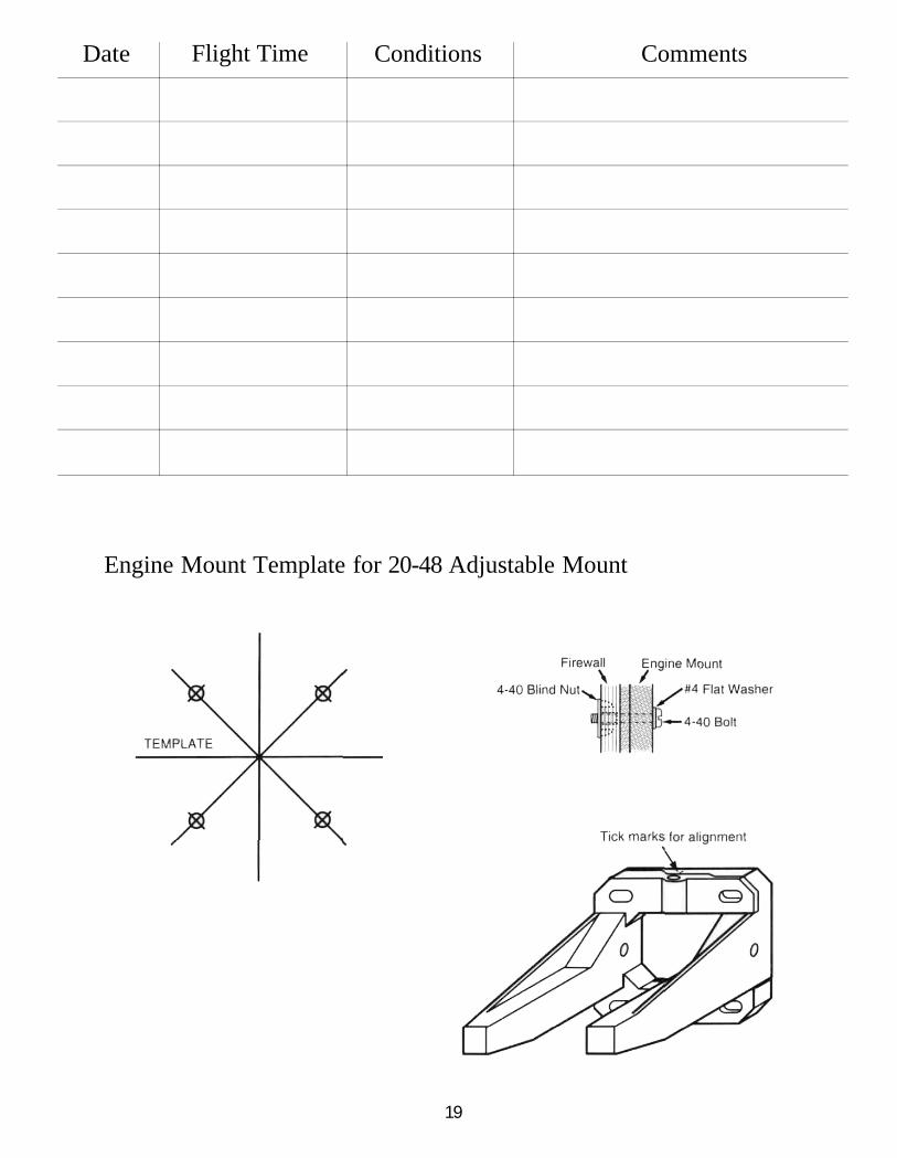
D 36. Draw a vertical and horizontal centerline on the1/4" plywood firewall. Cut the engine mount templatefrom the back of this booklet and tack glue it to thefirewall, aligned with the centerlines. Drill a 1/8" bolthole at each of the marked locations.
D 34. Locate the 3/8" plywood firewall doubler and
10
D 37. Cut the "spreader bar" off each mount half. Trimoff any burrs or flashing, then snap the mount halvestogether. Bolt the mount to the firewall with four 4-40 x1" screws and 4-40 blind nuts. Tightening the screwswill draw the blind nuts into position.
D 40. Temporarily install the engine on the mount withtwo #4 x 1/2" sheet metal screws. Mark the location ofthe throttle pushrod. Remove the engine and drill a3/16" hole for the outer pushrod tube.
D 41. Secure the engine to the mount with four #4 x1/2" sheet metal screws.
D 38. Test fit your engine to the mount. Adjust thewidth of the rails to fit the engine. Tighten the mountingscrews securely. Apply a couple of strips of maskingtape to the rails, position the engine, then mark theengine's mounting holes onto the rails (masking tape)with a pen or pencil.
D 39. Remove the engine and drill the rails where markedwith a 3/32" drill bit. Try to keep the holes straight andvertical. You may use #4 \ 1/2" sheet metal screws tomount the engine, or tap the holes with a 4-40 tap.
D 42. Use a small piece of coarse sandpaper to scuff upthe inner floor of the aluminum channel in the areaaround the front 11/64" bolt hole.
11
D 43. Insert one of the 8-32 x 1/2" machine screws intothe hole so that it sticks out the bottom of the channeland glue it in place with plenty of thick C/A or epoxy.This screw will be covered by the battery packprohibiting a screwdriver from being used to keep itfrom turning, so glue it securely but be very careful notto get any glue on the threads.
D 44. Use some nylon reinforced strapping tape tosecurely hold the battery pack on the front end of thechannel. Square battery packs fit very nicely but mostflat packs will also fit, just tape them flat onto thechannel. The battery should protrude approximately 1/8"past the end of the channel to keep the fuel tank fromrubbing against the end of the channel.
D 45. The servos are "press fit" into the aluminumchannel and then held in place with nylon strapping tape.Standard size servos should fit very nicely and smallerservos can be held in place by using a piece of wood tofill the space between theservo sides and thechannel. Large servoswill not work in theSTURDY BIRDY. Theservos should be placed asfar forward in the channelas possible and right nextto each other, but do notoverlap the servomounting lugs. the fronttwo servos should be
mounted with their servo output shafts towards the backof the plane and the back servo should have its outputshaft towards the front of the plane. The servo wiresshould be routed out to the side of the servo withoutgoing under any servos. Wrap two layers of nylonstrapping tape all the way around each servo and thealuminum channel to hold it in place. Hook up the entireradio system and turn it on (see the instructions includedwith your radio). Adjust the transmitter trims so they arein the middle of their slots. Remove the screws that holdthe servo horns in place and adjust the horns so that theyare perpendicular to the servo. This will be their neutralposition. It is a good idea to use single arm servo hornsrather than the round horns most servos come with. Thesketch shows how to cut a horn for use here. Replace thescrews that hold the horns in place. (See the photo atstep 49).
D 46. Attach the stabilizer/elevatorto the back of the channel usingtwo 4-40 x 5/8" machine screws,two #4 flat washers, two 4-40 lockwashers, and two 4-40 nuts. Thesketch shows how the pieces areinstalled. The pre-bent tail skid isheld in place by the rear screw.
D 47. Press the fin/rudder into the channel with theback edge of the fin even with the back edge of thechannel as shown in the photo.
12
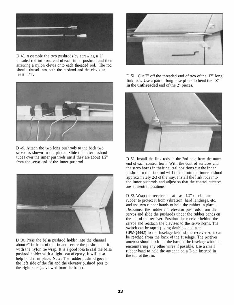
D 48. Assemble the two pushrods by screwing a 1"threaded rod into one end of each inner pushrod and thenscrewing a nylon clevis onto each threaded rod. The rodshould thread into both the pushrod and the clevis atleast 1/4".
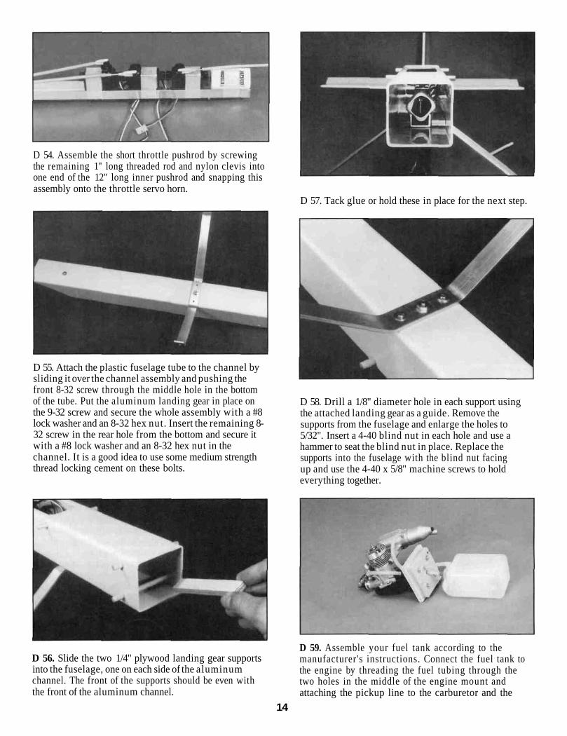
D 49. Attach the two long pushrods to the back twoservos as shown in the photo. Slide the outer pushrodtubes over the inner pushrods until they are about 1/2"from the servo end of the inner pushrod.
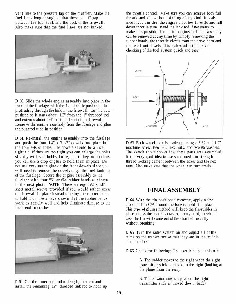
D 50. Press the balsa pushrod holder into the channelabout 6" in front of the fin and secure the pushrods to itwith the nylon tie wrap. It is a good idea to seal the balsapushrod holder with a light coat of epoxy, it will alsohelp hold it in place. Note: The rudder pushrod goes tothe left side of the fin and the elevator pushrod goes tothe right side (as viewed from the back).
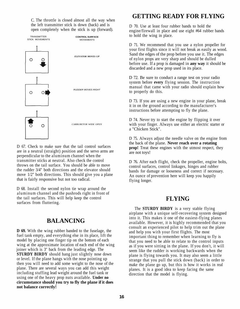
D 51. Cut 2" off the threaded end of two of the 12" longlink rods. Use a pair of long nose pliers to bend the "Z"in the unthreaded end of the 2" pieces.
D 52. Install the link rods in the 2nd hole from the outerend of each control horn. With the control surfaces andthe servo horns in their neutral positions cut the innerpushrod so the link rod will thread into the inner pushrodapproximately 2/3 of the way. Install the link rods intothe inner pushrods and adjust so that the control surfacesare at neutral positions.
D 53. Wrap the receiver in at least 1/4" thick foamrubber to protect it from vibration, hard landings, etc.and use two rubber bands to hold the rubber in place.Disconnect the rudder and elevator pushrods from theservos and slide the pushrods under the rubber bands onthe top of the receiver. Position the receiver behind theservos and reattach the clevises to the servo horns. Theswitch can be taped (using double-sided tapeGPMQ4442) to the fuselage behind the receiver so it canbe reached from the back of the fuselage. The receiverantenna should exit out the back of the fuselage withoutencountering any other wires if possible. Use a smallrubber band to hold the antenna on a T-pin inserted inthe top of the fin.
13
D 54. Assemble the short throttle pushrod by screwingthe remaining 1" long threaded rod and nylon clevis intoone end of the 12" long inner pushrod and snapping thisassembly onto the throttle servo horn.
D 57. Tack glue or hold these in place for the next step.
D 55. Attach the plastic fuselage tube to the channel bysliding it over the channel assembly and pushing thefront 8-32 screw through the middle hole in the bottomof the tube. Put the aluminum landing gear in place onthe 9-32 screw and secure the whole assembly with a #8lock washer and an 8-32 hex nut. Insert the remaining 8-32 screw in the rear hole from the bottom and secure itwith a #8 lock washer and an 8-32 hex nut in thechannel. It is a good idea to use some medium strengththread locking cement on these bolts.
D 58. Drill a 1/8" diameter hole in each support usingthe attached landing gear as a guide. Remove thesupports from the fuselage and enlarge the holes to5/32". Insert a 4-40 blind nut in each hole and use ahammer to seat the blind nut in place. Replace thesupports into the fuselage with the blind nut facingup and use the 4-40 x 5/8" machine screws to holdeverything together.
D 56. Slide the two 1/4" plywood landing gear supportsinto the fuselage, one on each side of the aluminumchannel. The front of the supports should be even withthe front of the aluminum channel.
D 59. Assemble your fuel tank according to themanufacturer's instructions. Connect the fuel tank tothe engine by threading the fuel tubing through thetwo holes in the middle of the engine mount andattaching the pickup line to the carburetor and the
14
vent line to the pressure tap on the muffler. Make thefuel lines long enough so that there is a 1" gapbetween the fuel tank and the back of the firewall.Also make sure that the fuel lines are not kinked.
D 60. Slide the whole engine assembly into place in thefront of the fuselage with the 12" throttle pushrod tubeprotruding through the hole in the firewall. Cut the outerpushrod so it starts about 1/2" from the 1" threaded rodand extends about 1/4" past the front of the firewall.Remove the engine assembly from the fuselage and gluethe pushrod tube in position.
D 61. Re-install the engine assembly into the fuselageand push the four 1/4" x 3-1/2" dowels into place inthe four sets of holes. The dowels should be a nicetight fit. If they are too tight you can enlarge the holesslightly with you hobby knife, and if they are too looseyou can use a drop of glue to hold them in place. Donot use very much glue on the front dowels since youwil l need to remove the dowels to get the fuel tank outof the fuselage. Secure the engine assembly to thefuselage with four #62 or #64 rubber bands as shownin the next photo. NOTE: There are eight #2 x 3/8"sheet metal screws provided if you would rather screwthe firewall in place instead of using the rubber bandsto hold it on. Tests have shown that the rubber bandswork extremely well and help eliminate damage to thefront end in crashes.
D 62. Cut the inner pushrod to length, then cut andinstall the remaining 12" threaded link rod to hook up
the throttle control. Make sure you can achieve both fullthrottle and idle without binding of any kind. It is alsonice if you can shut the engine off at low throttle and fulldown throttle trim. Bend the link rod if necessary tomake this possible. The entire engine/fuel tank assemblycan be removed at any time by simply removing therubber bands, the throttle clevis from the servo horn andthe two front dowels. This makes adjustments andchecking of the fuel system quick and easy.
D 63. Each wheel axle is made up using a 6-32 x 1-1/2"machine screw, two 6-32 hex nuts, and two #6 washers.The sketch above shows how these parts area assembled.It is a very good idea to use some medium strengththread locking cement between the screw and the hexnuts. Also make sure that the wheel can turn freely.
FINAL ASSEMBLYD 64. With the fin positioned correctly, apply a fewdrops of thin C/A around the base to hold it in place.This type of gluing method will keep the fin/rudder inplace unless the plane is crashed pretty hard, in whichcase the fin will come out of the channel, usuallywithout breaking.
D 65. Turn the radio system on and adjust all of thetrims on the transmitter so that they are in the middleof their slots.
D 66. Check the following: The sketch helps explain it.
A. The rudder moves to the right when the righttransmitter stick is moved to the right (looking atthe plane from the rear).
B. The elevator moves up when the righttransmitter stick is moved down (back).
15
C. The throttle is closed almost all the way whenthe left transmitter stick is down (back) and isopen completely when the stick is up (forward).
TRANSMITTERSTICK MOVEMENTS
CONTROL SURFACEMOVEMENTS
ELEVATOR MOVES UP
RUDDER MOVES RIGHT
CARBURETOR WIDE OPEN
D 67. Check to make sure that the tail control surfacesare in a neutral (straight) position and the servo arms areperpendicular to the aluminum channel when thetransmitter sticks at neutral. Also check the controlthrows on the tail surface. You should be able to movethe rudder 3/4" both directions and the elevator shouldmove 1/2" both directions. This should give you a planethat is fairly responsive but not too radical.
D 68. Install the second nylon tie wrap around thealuminum channel and the pushrods right in front ofthe tail surfaces. This will help keep the controlsurfaces from fluttering.
BALANCINGD 69. With the wing rubber banded to the fuselage, thefuel tank empty, and everything else in its place, lift themodel by placing one finger tip on the bottom of eachwing at the approximate location of each end of the wingjoiner which is 3" back from the leading edge. TheSTURDY BIRDY should hang just slightly nose downor level. If the plane hangs with the nose pointing upthen you will need to add some weight to the nose of theplane. There are several ways you can add this weightincluding stuffing lead weight around the fuel tank orusing one of the heavy prop nuts available. Under nocircumstance should you try to fly the plane if it doesnot balance correctly!
GETTING READY FOR FLYINGD 70. Use at least four rubber bands to hold theengine/firewall in place and use eight #64 rubber bandsto hold the wing in place.
D 71. We recommend that you use a nylon propeller foryour first flights since it will not break as easily as wood.Sand the edges of the prop before you use it. The edgesof nylon props are very sharp and should be dulledbefore use. If a prop is damaged in any way it should bediscarded and a new prop used in its place.
D 72. Be sure to conduct a range test on your radiosystem before every flying session. The instructionmanual that came with your radio should explain howto properly do this.
D 73. If you are using a new engine in your plane, breakit in on the ground according to the manufacturer'sinstructions before attempting to fly the plane.
D 74. Never try to start the engine by flipping it overwith your finger. Always use either an electric starter ora "Chicken Stick".
D 75. Always adjust the needle valve on the engine fromthe back of the plane. Never reach over a rotatingprop! Treat these engines with the utmost respect, theyare not toys!
D 76. After each flight, check the propeller, engine bolts,control surfaces, control linkages, hinges and rubberbands for damage or looseness and correct if necessary.An ounce of prevention here will keep you happilyflying longer.
FLYINGThe STURDY BIRDY is a very stable flying
airplane with a unique self-recovering system designedinto it. This makes it one of the easiest-flying planesavailable. However, it is highly recommended that youconsult an experienced pilot to help trim out the planeand help you with your first flights. The mostimportant thing to remember when learning to fly isthat you need to be able to relate to the control inputsas if you were sitting in the plane. If you don't, it willseem like the rudder is working backwards when theplane is flying towards you. It may also seem a littlestrange that you pull the stick down (back) in order tomake the plane go up, but this is how it works in realplanes. It is a good idea to keep facing the samedirection that the model is flying.
16
The STURDY BIRDY should be hand launched intothe wind for your first flights. Have a helper hold theplane firmly behind the landing gear with the wingslevel while you check the controls. Advance the throttleto full throttle and your helper should then take a fewrunning steps and let the plane fly out of his hand with aslight push (being careful to keep the wings level). Astrong throw is not necessary. Be prepared to make anyinitial controls to keep the plane climbing slightly andflying straight.
Your control inputs should be very gentle until theplane has climbed high enough to be out of danger ofhitting any ground based objects (especially theground). Once you have reached a safe altitude, trimthe plane for straight and level flight with the enginerunning about half throttle. If you get disoriented orthe plane does not seem to be doing what you think itshould, just release the control sticks and the planewill right itself. If you see that the plane is heading fordanger which you can not prevent, reduce the throttleto idle and pull the elevator stick back (up elevator) toreduce the impact speed.
When the plane banks into a turn it is normal for thenose to drop down so be prepared to put in a little upelevator to keep it flying level.
Once you are familiar with how the STURDYBIRDY handles under power, pull the throttle back tonear idle and slow the plane down. Be sure to do this at asafe altitude! Feed in up elevator to try to keep the planeflying at the same altitude. If the plane stalls (falls off toone side abruptly) just release the control sticks, advancethe throttle to at least 1/2 and gently pull in some upelevator. Try to determine the slowest speed the planewill fly at and remember that you need to stay above thatspeed when landing and taking off to avoid a stall.
If you find the plane getting too high and it is hard todetermine what it is doing, reduce the throttle to idle andbe patient. The STURDY BIRDY will lose altitudefairly quickly and you can resume control.
When preparing to land it is a good idea to makeseveral practice passes from a safe altitude and graduallyget lower until you feel comfortable with your approach.Then on one of your next passes, just decrease thethrottle and the plane will land by itself. Landing isreally not very tricky if you just concentrate on guidingthe plane with the rudder where you want it to go and letit settle to the ground. Of course it helps to fly at a fieldthat is big enough so you don't have to worry aboutwhere you need to land.
The STURDY BIRDY also handles very nicely onthe ground despite the fact that it is a tail dragger withouta steerable tail wheel. When taxiing in grass, hold in upelevator until the plane is moving pretty well to helpkeep it from nosing over. To steer the model when it ismoving slow, throw in full rudder and use bursts ofthrottle to move the plane around.
REPAIRINGThe STURDY BIRDY is very tough, but there may
be crashes hard enough to break parts of the plane.
The fuselage should not be repaired. It is inexpensiveand very easy and quick to replace. Due to the nature ofplastics it is very hard to properly mend if cracked orbroken and should be replaced for safety's sake.
The foam wing will really take a beating andsurvive. Small dents and dings can be removed bypatching or re-heating the covering material. A brokenwing can be quickly repaired with epoxy, but check thenylon tape and replace it if needed. If the wings getbent you can straighten them by bending them theopposite direction and adding a couple more strips ofstrapping tape. It is important that the wings are kept intheir original configuration with the molded-in washout(wing twist). This gives the STURDY BIRDY it'sexceptional recovery characteristics.
The tail surfaces can be repaired with C/A glues, ornew surfaces can be cut from 1/4" balsa available fromyour local hobby shop.
If dirt gets into the carburetor or onto the engine itshould be cleaned off before it has a chance to get insidethe engine and cause damage.
17

Pilots LogUse this to record your flights, it's fun to look back on!
Date Flight Time Conditions Comments
18
Date Flight Time Conditions Comments
Engine Mount Template for 20-48 Adjustable Mount
19
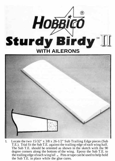
WITH AILERONS
1. Locate the two 15/32" x 3/8 x 26-1/2" Sub Trailing Edge pieces (SubT.E.). Trial fit the Sub T.E. against the trailing edge of each wing half.The Sub T.E. should be oriented as shown in the sketch with the 90degree corners along the bottom of the wing. Epoxy the Sub T.E. tothe trailing edge of each wing half . Pins or tape can be used to help holdthe Sub T.E. in place while the glue cures.
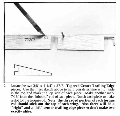
2. Locate the two 3/8" x 1-1/4" x 37/8" Tapered Center Trailing Edgepieces. Use the inset sketch above to help you determine which sideis the top and mark the lop side of each piece. Make another mark7/16" from the "inboard" end of each piece. Notch each piece to makea slot for the torque rod. Note: the threaded portion of each torquerod should stick out the top of each wing. Also there will be a"right" and a "left" center trailing edge piece so don't make twoexactly alike.
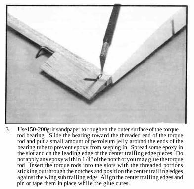
3. Use150-200grit sandpaper to roughen the outer surface of the torquerod bearing Slide the bearing toward the threaded end of the torquerod and put a small amount of petroleum jelly around the ends of thebearing tube to prevent epoxy from seeping in Spread some epoxy inthe slot and on the leading edge of the center trailing edge pieces Donot apply any epoxy within 1 /4" of the notch or you may glue the torquerod Insert the torque rods into the slots with the threaded portionssticking out through the notches and position the center trailing edgesagainst the wing sub trailing edge Align the center trailing edges andpin or tape them in place while the glue cures.
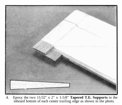
4. Epoxy the two 11/32" x 2" x 1-5/8" Tapered T.E. Supports to theinboard bottom of each center trailing edge as shown in the photo.
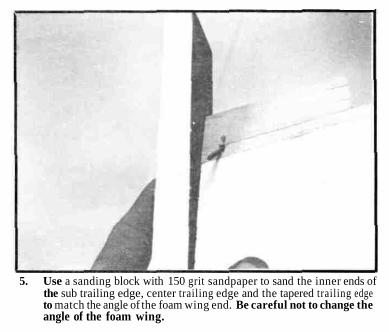
5. Use a sanding block with 150 grit sandpaper to sand the inner ends ofthe sub trailing edge, center trailing edge and the tapered trailing edgeto match the angle of the foam wing end. Be careful not to change theangle of the foam wing.
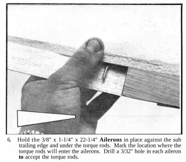
6. Hold the 3/8" x 1-1/4" x 22-1/4" Ailerons in place against the subtrailing edge and under the torque rods. Mark the location where thetorque rods will enter the ailerons. Drill a 3/32" hole in each aileronto accept the torque rods.
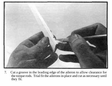
7. Cut a groove in the leading edge of the aileron to allow clearance forthe torque rods. Trial fit the ailerons in place and cut as necessary untilthey fit.
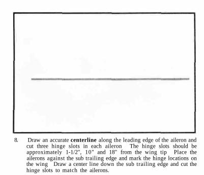
8. Draw an accurate centerline along the leading edge of the aileron andcut three hinge slots in each aileron The hinge slots should beapproximately 1-1/2", 10" and 18" from the wing tip Place theailerons against the sub trailing edge and mark the hinge locations onthe wing Draw a center line down the sub trailing edge and cut thehinge slots to match the ailerons.
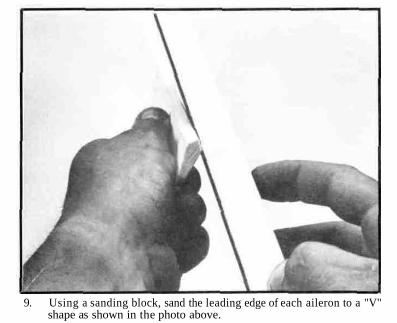
9. Using a sanding block, sand the leading edge of each aileron to a "V"shape as shown in the photo above.
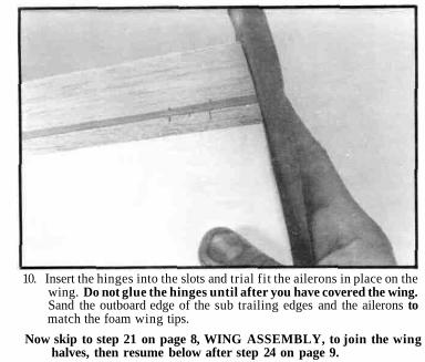
10. Insert the hinges into the slots and trial fit the ailerons in place on thewing. Do not glue the hinges until after you have covered the wing.Sand the outboard edge of the sub trailing edges and the ailerons tomatch the foam wing tips.
Now skip to step 21 on page 8, WING ASSEMBLY, to join the winghalves, then resume below after step 24 on page 9.
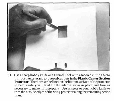
11. Use a sharp hobby knife or a Dremel Tool with a tapered cutting bit totrim out the servo and torque rod cut outs in the Plastic Center SectionProtector. There are scribe lines on the bottom surface of the protectorto help guide you Trial fit the aileron servo in place and trim asnecessary to make it fit properly Use scissors or your hobby knife totrim the outside edges of the wing protector along the remaining scribelines.
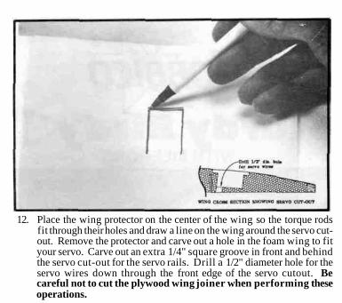
12. Place the wing protector on the center of the wing so the torque rodsfit through their holes and draw a line on the wing around the servo cut-out. Remove the protector and carve out a hole in the foam wing to fityour servo. Carve out an extra 1/4" square groove in front and behindthe servo cut-out for the servo rails. Drill a 1/2" diameter hole for theservo wires down through the front edge of the servo cutout. Becareful not to cut the plywood wing joiner when performing theseoperations.
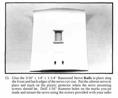
13. Glue the 3/16" x 1/4" x 1-1/4" Basswood Servo Rails in place alongthe front and back edges of the servo cut-out. Put the aileron servo inplace and mark on the plastic protector where the servo mountingscrews should be. Drill 1/16" diameter holes on the marks you justmade and mount the servo using the screws provided with your radio
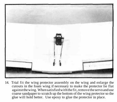
14. Trial fit the wing protector assembly on the wing and enlarge thecutouts in the foam wing if necessary to make the protector lie flatagainst the wing. When satisfied with the fit, remove the servo and usecoarse sandpaper to scratch up the bottom of the wing protector so theglue will hold better. Use epoxy to glue the protector in place.
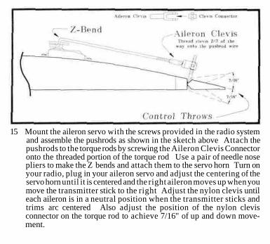
15 Mount the aileron servo with the screws provided in the radio systemand assemble the pushrods as shown in the sketch above Attach thepushrods to the torque rods by screwing the Aileron Clevis Connectoronto the threaded portion of the torque rod Use a pair of needle nosepliers to make the Z bends and attach them to the servo horn Turn onyour radio, plug in your aileron servo and adjust the centering of theservo horn until it is centered and the right aileron moves up when youmove the transmitter stick to the right Adjust the nylon clevis untileach aileron is in a neutral position when the transmitter sticks andtrims arc centered Also adjust the position of the nylon clevisconnector on the torque rod to achieve 7/16" of up and down move-ment.