Embed Size (px)
Citation preview

HANDY MIG
OPERATOR’S MANUAL
IM756-AAugust, 2005
Safety Depends on YouLincoln arc welding and cuttingequipment is designed and builtwith safety in mind. However, youroverall safety can be increased byproper installation ... and thought-ful operation on your part. DONOT INSTALL, OPERATE ORREPAIR THIS EQUIPMENTWITHOUT READING THISMANUAL AND THE SAFETYPRECAUTIONS CONTAINEDTHROUGHOUT. And, mostimportantly, think before you actand be careful.
For use with machine Code Number:10919, 11205
• Sales and Service through Subsidiaries and Distributors Worldwide •
Cleveland, Ohio 44117-1199 U.S.A. TEL: 216.481.8100 FAX: 216.486.1751 WEB SITE: www.lincolnelectric.com
• World's Leader in Welding and Cutting Products •
ISO 9001
CERTIFICATE NUMBER: 30273
Designed and Manufactured Under aQuality Program Certified byABS Quality Evaluations, Inc.to ISO 9001 Requirements.
QMS
ANSI RAB
Copyright © 2005 Lincoln Global Inc.
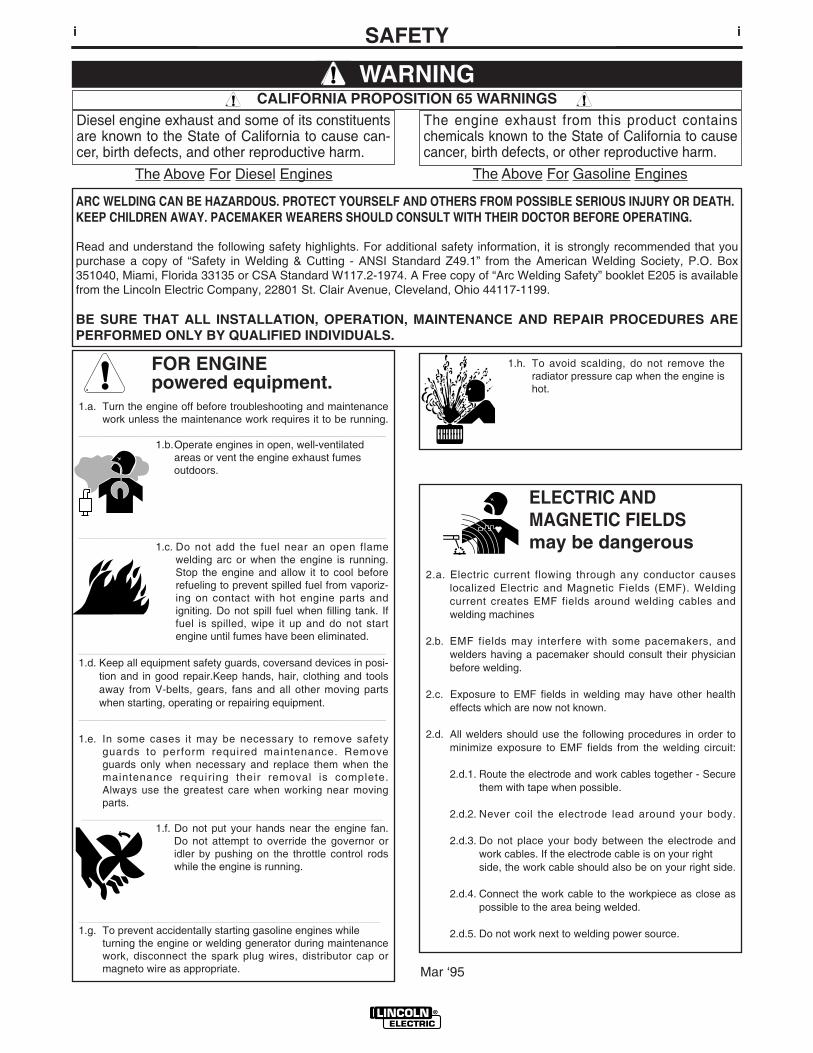
FOR ENGINEpowered equipment.
1.a. Turn the engine off before troubleshooting and maintenancework unless the maintenance work requires it to be running.
____________________________________________________1.b.Operate engines in open, well-ventilated
areas or vent the engine exhaust fumes outdoors.
____________________________________________________1.c. Do not add the fuel near an open flame
welding arc or when the engine is running.Stop the engine and allow it to cool beforerefueling to prevent spilled fuel from vaporiz-ing on contact with hot engine parts andigniting. Do not spill fuel when filling tank. Iffuel is spilled, wipe it up and do not startengine until fumes have been eliminated.
____________________________________________________1.d. Keep all equipment safety guards, coversand devices in posi-
tion and in good repair.Keep hands, hair, clothing and toolsaway from V-belts, gears, fans and all other moving partswhen starting, operating or repairing equipment.
____________________________________________________
1.e. In some cases it may be necessary to remove safetyguards to perform required maintenance. Removeguards only when necessary and replace them when themaintenance requiring their removal is complete.Always use the greatest care when working near movingparts.
___________________________________________________1.f. Do not put your hands near the engine fan.
Do not attempt to override the governor oridler by pushing on the throttle control rodswhile the engine is running.
___________________________________________________1.g. To prevent accidentally starting gasoline engines while
turning the engine or welding generator during maintenancework, disconnect the spark plug wires, distributor cap ormagneto wire as appropriate.
iSAFETYi
ARC WELDING CAN BE HAZARDOUS. PROTECT YOURSELF AND OTHERS FROM POSSIBLE SERIOUS INJURY OR DEATH.KEEP CHILDREN AWAY. PACEMAKER WEARERS SHOULD CONSULT WITH THEIR DOCTOR BEFORE OPERATING.
Read and understand the following safety highlights. For additional safety information, it is strongly recommended that youpurchase a copy of “Safety in Welding & Cutting - ANSI Standard Z49.1” from the American Welding Society, P.O. Box351040, Miami, Florida 33135 or CSA Standard W117.2-1974. A Free copy of “Arc Welding Safety” booklet E205 is availablefrom the Lincoln Electric Company, 22801 St. Clair Avenue, Cleveland, Ohio 44117-1199.
BE SURE THAT ALL INSTALLATION, OPERATION, MAINTENANCE AND REPAIR PROCEDURES AREPERFORMED ONLY BY QUALIFIED INDIVIDUALS.
WARNING
Mar ‘95
ELECTRIC AND MAGNETIC FIELDSmay be dangerous
2.a. Electric current flowing through any conductor causes localized Electric and Magnetic Fields (EMF). Welding current creates EMF fields around welding cables and welding machines
2.b. EMF fields may interfere with some pacemakers, andwelders having a pacemaker should consult their physicianbefore welding.
2.c. Exposure to EMF fields in welding may have other healtheffects which are now not known.
2.d. All welders should use the following procedures in order tominimize exposure to EMF fields from the welding circuit:
2.d.1. Route the electrode and work cables together - Securethem with tape when possible.
2.d.2. Never coil the electrode lead around your body.
2.d.3. Do not place your body between the electrode andwork cables. If the electrode cable is on your right side, the work cable should also be on your right side.
2.d.4. Connect the work cable to the workpiece as close aspossible to the area being welded.
2.d.5. Do not work next to welding power source.
1.h. To avoid scalding, do not remove theradiator pressure cap when the engine ishot.
Diesel engine exhaust and some of its constituentsare known to the State of California to cause can-cer, birth defects, and other reproductive harm.
The engine exhaust from this product containschemicals known to the State of California to causecancer, birth defects, or other reproductive harm.
CALIFORNIA PROPOSITION 65 WARNINGS
The Above For Diesel Engines The Above For Gasoline Engines
iiSAFETYii
ARC RAYS can burn.4.a. Use a shield with the proper filter and cover
plates to protect your eyes from sparks andthe rays of the arc when welding or observingopen arc welding. Headshield and filter lensshould conform to ANSI Z87. I standards.
4.b. Use suitable clothing made from durable flame-resistantmaterial to protect your skin and that of your helpers fromthe arc rays.
4.c. Protect other nearby personnel with suitable, non-flammablescreening and/or warn them not to watch the arc nor exposethemselves to the arc rays or to hot spatter or metal.
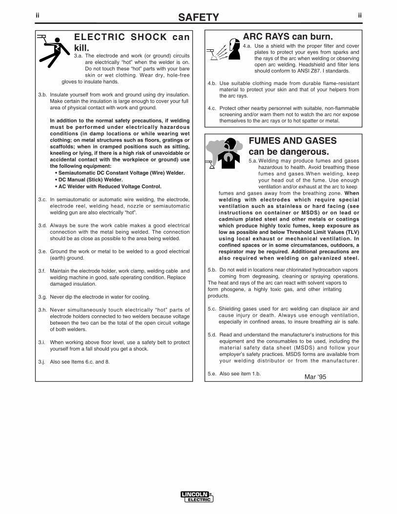
ELECTRIC SHOCK cankill.3.a. The electrode and work (or ground) circuits
are electrically “hot” when the welder is on.Do not touch these “hot” parts with your bareskin or wet clothing. Wear dry, hole-free
gloves to insulate hands.
3.b. Insulate yourself from work and ground using dry insulation.Make certain the insulation is large enough to cover your fullarea of physical contact with work and ground.
In addition to the normal safety precautions, if weldingmust be performed under electrically hazardousconditions (in damp locations or while wearing wetclothing; on metal structures such as floors, gratings orscaffolds; when in cramped positions such as sitting,kneeling or lying, if there is a high risk of unavoidable oraccidental contact with the workpiece or ground) usethe following equipment:
• Semiautomatic DC Constant Voltage (Wire) Welder.• DC Manual (Stick) Welder.• AC Welder with Reduced Voltage Control.
3.c. In semiautomatic or automatic wire welding, the electrode,electrode reel, welding head, nozzle or semiautomaticwelding gun are also electrically “hot”.
3.d. Always be sure the work cable makes a good electricalconnection with the metal being welded. The connectionshould be as close as possible to the area being welded.
3.e. Ground the work or metal to be welded to a good electrical(earth) ground.
3.f. Maintain the electrode holder, work clamp, welding cable andwelding machine in good, safe operating condition. Replacedamaged insulation.
3.g. Never dip the electrode in water for cooling.
3.h. Never simultaneously touch electrically “hot” parts ofelectrode holders connected to two welders because voltagebetween the two can be the total of the open circuit voltageof both welders.
3.i. When working above floor level, use a safety belt to protectyourself from a fall should you get a shock.
3.j. Also see Items 6.c. and 8.
FUMES AND GASEScan be dangerous.5.a. Welding may produce fumes and gases
hazardous to health. Avoid breathing thesefumes and gases.When welding, keepyour head out of the fume. Use enoughventilation and/or exhaust at the arc to keep
fumes and gases away from the breathing zone. Whenwelding with electrodes which require specialventilation such as stainless or hard facing (seeinstructions on container or MSDS) or on lead orcadmium plated steel and other metals or coatingswhich produce highly toxic fumes, keep exposure aslow as possible and below Threshold Limit Values (TLV)using local exhaust or mechanical ventilation. Inconfined spaces or in some circumstances, outdoors, arespirator may be required. Additional precautions arealso required when welding on galvanized steel.
5.b. Do not weld in locations near chlorinated hydrocarbon vaporscoming from degreasing, cleaning or spraying operations.
The heat and rays of the arc can react with solvent vapors toform phosgene, a highly toxic gas, and other irritating products.
5.c. Shielding gases used for arc welding can displace air andcause injury or death. Always use enough ventilation,especially in confined areas, to insure breathing air is safe.
5.d. Read and understand the manufacturer’s instructions for thisequipment and the consumables to be used, including thematerial safety data sheet (MSDS) and follow youremployer’s safety practices. MSDS forms are available fromyour welding distributor or from the manufacturer.
5.e. Also see item 1.b. Mar ‘95
FOR ELECTRICALLYpowered equipment.
8.a. Turn off input power using the disconnectswitch at the fuse box before working onthe equipment.
8.b. Install equipment in accordance with the U.S. NationalElectrical Code, all local codes and the manufacturer’srecommendations.
8.c. Ground the equipment in accordance with the U.S. NationalElectrical Code and the manufacturer’s recommendations.
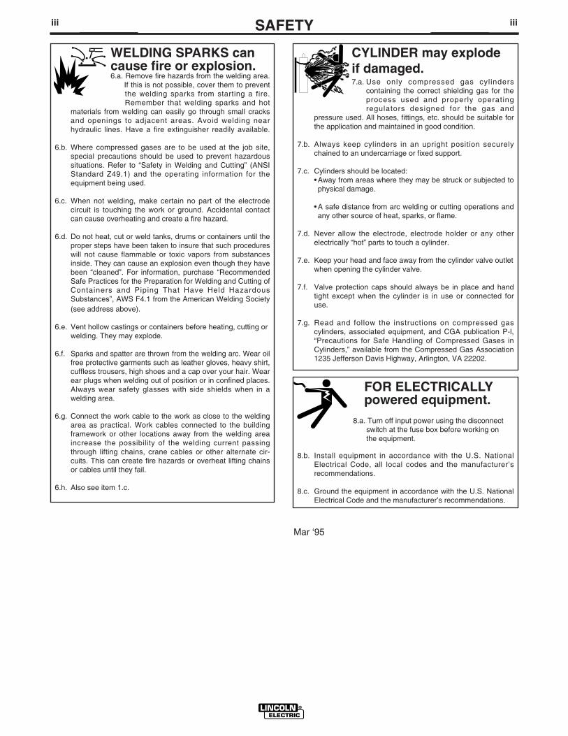
CYLINDER may explodeif damaged.7.a. Use only compressed gas cylinders
containing the correct shielding gas for theprocess used and properly operatingregulators designed for the gas and
pressure used. All hoses, fittings, etc. should be suitable forthe application and maintained in good condition.
7.b. Always keep cylinders in an upright position securelychained to an undercarriage or fixed support.
7.c. Cylinders should be located:• Away from areas where they may be struck or subjected tophysical damage.
• A safe distance from arc welding or cutting operations andany other source of heat, sparks, or flame.
7.d. Never allow the electrode, electrode holder or any otherelectrically “hot” parts to touch a cylinder.
7.e. Keep your head and face away from the cylinder valve outletwhen opening the cylinder valve.
7.f. Valve protection caps should always be in place and handtight except when the cylinder is in use or connected foruse.
7.g. Read and follow the instructions on compressed gascylinders, associated equipment, and CGA publication P-l,“Precautions for Safe Handling of Compressed Gases inCylinders,” available from the Compressed Gas Association1235 Jefferson Davis Highway, Arlington, VA 22202.
iiiSAFETYiii
Mar ‘95
WELDING SPARKS cancause fire or explosion.6.a. Remove fire hazards from the welding area.
If this is not possible, cover them to preventthe welding sparks from starting a fire.Remember that welding sparks and hot
materials from welding can easily go through small cracksand openings to adjacent areas. Avoid welding nearhydraulic lines. Have a fire extinguisher readily available.
6.b. Where compressed gases are to be used at the job site,special precautions should be used to prevent hazardoussituations. Refer to “Safety in Welding and Cutting” (ANSIStandard Z49.1) and the operating information for theequipment being used.
6.c. When not welding, make certain no part of the electrodecircuit is touching the work or ground. Accidental contactcan cause overheating and create a fire hazard.
6.d. Do not heat, cut or weld tanks, drums or containers until theproper steps have been taken to insure that such procedureswill not cause flammable or toxic vapors from substancesinside. They can cause an explosion even though they havebeen “cleaned”. For information, purchase “RecommendedSafe Practices for the Preparation for Welding and Cutting ofContainers and Piping That Have Held HazardousSubstances”, AWS F4.1 from the American Welding Society(see address above).
6.e. Vent hollow castings or containers before heating, cutting orwelding. They may explode.
6.f. Sparks and spatter are thrown from the welding arc. Wear oilfree protective garments such as leather gloves, heavy shirt,cuffless trousers, high shoes and a cap over your hair. Wearear plugs when welding out of position or in confined places.Always wear safety glasses with side shields when in awelding area.
6.g. Connect the work cable to the work as close to the weldingarea as practical. Work cables connected to the buildingframework or other locations away from the welding areaincrease the possibility of the welding current passingthrough lifting chains, crane cables or other alternate cir-cuits. This can create fire hazards or overheat lifting chainsor cables until they fail.
6.h. Also see item 1.c.
ivSAFETYiv
PRÉCAUTIONS DE SÛRETÉPour votre propre protection lire et observer toutes les instruc-tions et les précautions de sûreté specifiques qui parraissentdans ce manuel aussi bien que les précautions de sûretégénérales suivantes:
Sûreté Pour Soudage A L’Arc1. Protegez-vous contre la secousse électrique:
a. Les circuits à l’électrode et à la piéce sont sous tensionquand la machine à souder est en marche. Eviter toujourstout contact entre les parties sous tension et la peau nueou les vétements mouillés. Porter des gants secs et sanstrous pour isoler les mains.
b. Faire trés attention de bien s’isoler de la masse quand onsoude dans des endroits humides, ou sur un planchermetallique ou des grilles metalliques, principalement dans
les positions assis ou couché pour lesquelles unegrande partie du corps peut être en contact avec lamasse.
c. Maintenir le porte-électrode, la pince de masse, le câblede soudage et la machine à souder en bon et sûr étatdefonctionnement.
d.Ne jamais plonger le porte-électrode dans l’eau pour lerefroidir.
e. Ne jamais toucher simultanément les parties sous tensiondes porte-électrodes connectés à deux machines à soud-er parce que la tension entre les deux pinces peut être letotal de la tension à vide des deux machines.
f. Si on utilise la machine à souder comme une source decourant pour soudage semi-automatique, ces precautionspour le porte-électrode s’applicuent aussi au pistolet desoudage.
2. Dans le cas de travail au dessus du niveau du sol, se pro-téger contre les chutes dans le cas ou on recoit un choc. Nejamais enrouler le câble-électrode autour de n’importe quellepartie du corps.
3. Un coup d’arc peut être plus sévère qu’un coup de soliel,donc:
a. Utiliser un bon masque avec un verre filtrant appropriéainsi qu’un verre blanc afin de se protéger les yeux durayonnement de l’arc et des projections quand on soudeou quand on regarde l’arc.
b. Porter des vêtements convenables afin de protéger lapeau de soudeur et des aides contre le rayonnement del‘arc.
c. Protéger l’autre personnel travaillant à proximité ausoudage à l’aide d’écrans appropriés et non-inflamma-bles.
4. Des gouttes de laitier en fusion sont émises de l’arc desoudage. Se protéger avec des vêtements de protectionlibres de l’huile, tels que les gants en cuir, chemise épaisse,pantalons sans revers, et chaussures montantes.
5. Toujours porter des lunettes de sécurité dans la zone desoudage. Utiliser des lunettes avec écrans lateraux dans leszones où l’on pique le laitier.
6. Eloigner les matériaux inflammables ou les recouvrir afin deprévenir tout risque d’incendie dû aux étincelles.
7. Quand on ne soude pas, poser la pince à une endroit isolé dela masse. Un court-circuit accidental peut provoquer unéchauffement et un risque d’incendie.
8. S’assurer que la masse est connectée le plus prés possiblede la zone de travail qu’il est pratique de le faire. Si on placela masse sur la charpente de la construction ou d’autresendroits éloignés de la zone de travail, on augmente le risquede voir passer le courant de soudage par les chaines de lev-age, câbles de grue, ou autres circuits. Cela peut provoquerdes risques d’incendie ou d’echauffement des chaines et descâbles jusqu’à ce qu’ils se rompent.
9. Assurer une ventilation suffisante dans la zone de soudage.Ceci est particuliérement important pour le soudage de tôlesgalvanisées plombées, ou cadmiées ou tout autre métal quiproduit des fumeés toxiques.
10. Ne pas souder en présence de vapeurs de chlore provenantd’opérations de dégraissage, nettoyage ou pistolage. Lachaleur ou les rayons de l’arc peuvent réagir avec lesvapeurs du solvant pour produire du phosgéne (gas forte-ment toxique) ou autres produits irritants.
11. Pour obtenir de plus amples renseignements sur la sûreté,voir le code “Code for safety in welding and cutting” CSAStandard W 117.2-1974.
PRÉCAUTIONS DE SÛRETÉ POURLES MACHINES À SOUDER ÀTRANSFORMATEUR ET ÀREDRESSEUR
1. Relier à la terre le chassis du poste conformement au codede l’électricité et aux recommendations du fabricant. Le dis-positif de montage ou la piece à souder doit être branché àune bonne mise à la terre.
2. Autant que possible, I’installation et l’entretien du posteseront effectués par un électricien qualifié.
3. Avant de faires des travaux à l’ interieur de poste, ladebrancher à l’interrupteur à la boite de fusibles.
4. Garder tous les couvercles et dispositifs de sûreté à leurplace.
Mar. ‘93

vv
Thank You for selecting a QUALITY product by Lincoln Electric. We want youto take pride in operating this Lincoln Electric Company product••• as much pride as we have in bringing this product to you!
Read this Operators Manual completely before attempting to use this equipment. Save this manual and keep ithandy for quick reference. Pay particular attention to the safety instructions we have provided for your protection.The level of seriousness to be applied to each is explained below:
WARNINGThis statement appears where the information must be followed exactly to avoid serious personal injury orloss of life.
This statement appears where the information must be followed to avoid minor personal injury or damage tothis equipment.
CAUTION
Please Examine Carton and Equipment For Damage ImmediatelyWhen this equipment is shipped, title passes to the purchaser upon receipt by the carrier. Consequently, Claimsfor material damaged in shipment must be made by the purchaser against the transportation company at thetime the shipment is received.
Please record your equipment identification information below for future reference. This information can befound on your machine nameplate.
Product _________________________________________________________________________________
Model Number ___________________________________________________________________________
Code Number or Date Code_________________________________________________________________
Serial Number____________________________________________________________________________
Date Purchased___________________________________________________________________________
Where Purchased_________________________________________________________________________
Whenever you request replacement parts or information on this equipment, always supply the information youhave recorded above. The code number is especially important when identifying the correct replacement parts.
On-Line Product Registration
- Register your machine with Lincoln Electric either via fax or over the Internet.
• For faxing: Complete the form on the back of the warranty statement included in the literature packetaccompanying this machine and fax the form per the instructions printed on it.
• For On-Line Registration: Go to our WEB SITE at www.lincolnelectric.com. Choose “Quick Links” and then“Product Registration”. Please complete the form and submit your registration.

viviMASTER TABLE OF CONTENTS FOR ALL SECTIONS
PageInstallation .......................................................................................................Section A
Technical Specifications ........................................................................................A-1Identify and Locate Components ...........................................................................A-2Select Suitable Location ........................................................................................A-3Stacking.................................................................................................................A-3Changing Polarity ..................................................................................................A-3Gun Installation......................................................................................................A-3Input Connections..................................................................................................A-3Gas Connections ...................................................................................................A-3Shielding Gas Connections ...................................................................................A-4Code Requirements ..............................................................................................A-4
________________________________________________________________________Operation .........................................................................................................Section B
Safety Precautions ................................................................................................B-1General Description ...............................................................................................B-1Recommended Processes.....................................................................................B-1Operation Features and Controls .........................................................................B-1Design Features ....................................................................................................B-1Welding Capability .................................................................................................B-2Limitations..............................................................................................................B-2Controls and Settings ............................................................................................B-2Welding Operations ...............................................................................................B-2Shielding Gas ........................................................................................................B-3Making a Weld and Process Table ........................................................................B-4Cleaning Tip and Gas Nozzle ................................................................................B-5Changing Machine over to Feed Other Wire Sizes,Overload Protection...............B-5
________________________________________________________________________Accessories .....................................................................................................Section C
Accessories ...........................................................................................................C-1Replacement Parts ................................................................................................C-1
________________________________________________________________________Maintenance ....................................................................................................Section D
Safety Precautions ................................................................................................D-1Items Requiring No Maintenance ..........................................................................D-1Routine Maintenance.............................................................................................D-1Cleaning the Gun Liner..........................................................................................D-2Cleaning Components as Required.......................................................................D-2Component Replacement Procedures ..................................................................D-2Changing Contact Tip............................................................................................D-2Changing the Drive Roll.........................................................................................D-2Gun Assembly Removal ........................................................................................D-3Work Cable Installation..........................................................................................D-3
________________________________________________________________________Troubleshooting ..............................................................................................Section E
Safety Precautions.................................................................................................E-1How to Use Troubleshooting Guide.......................................................................E-1Troubleshooting Guide.........................................................................E-2 THRU E-4
________________________________________________________________________Wiring Diagrams ..............................................................................................Section F
Wiring Diagram .....................................................................................................F-1________________________________________________________________________
Parts Lists ....................................................................................................P437 Series
A-1
HANDY MIG
A-1
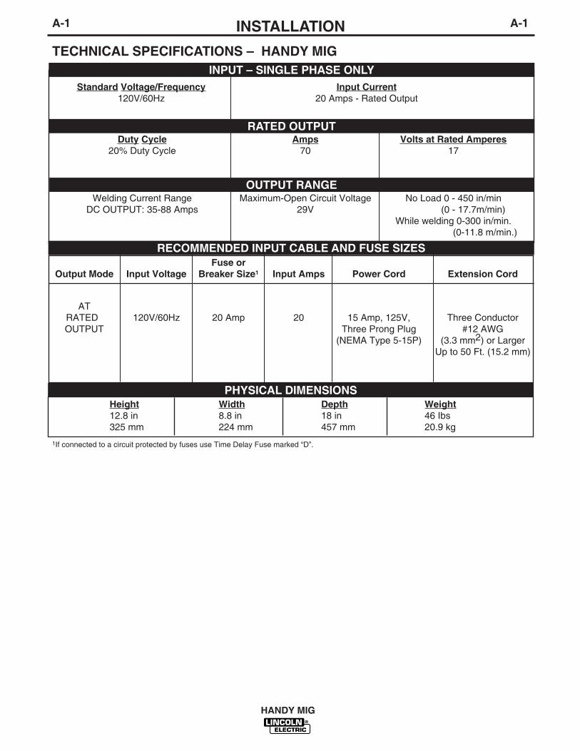
Fuse orOutput Mode Input Voltage Breaker Size1 Input Amps Power Cord Extension Cord
ATRATED 120V/60Hz 20 Amp 20 15 Amp, 125V, Three ConductorOUTPUT Three Prong Plug #12 AWG
(NEMA Type 5-15P) (3.3 mm2) or LargerUp to 50 Ft. (15.2 mm)
INSTALLATION
TECHNICAL SPECIFICATIONS – HANDY MIGINPUT – SINGLE PHASE ONLY
RATED OUTPUT
OUTPUT RANGE
RECOMMENDED INPUT CABLE AND FUSE SIZES
Height Width Depth Weight12.8 in 8.8 in 18 in 46 Ibs325 mm 224 mm 457 mm 20.9 kg
PHYSICAL DIMENSIONS
Standard Voltage/Frequency Input Current120V/60Hz 20 Amps - Rated Output
Duty Cycle Amps Volts at Rated Amperes20% Duty Cycle 70 17
Welding Current Range Maximum-Open Circuit Voltage No Load 0 - 450 in/minDC OUTPUT: 35-88 Amps 29V (0 - 17.7m/min)
While welding 0-300 in/min.(0-11.8 m/min.)
1If connected to a circuit protected by fuses use Time Delay Fuse marked “D”.
A-2INSTALLATION
HANDY MIG
A-2
Read entire installation section before startinginstallation.
SAFETY PRECAUTIONS
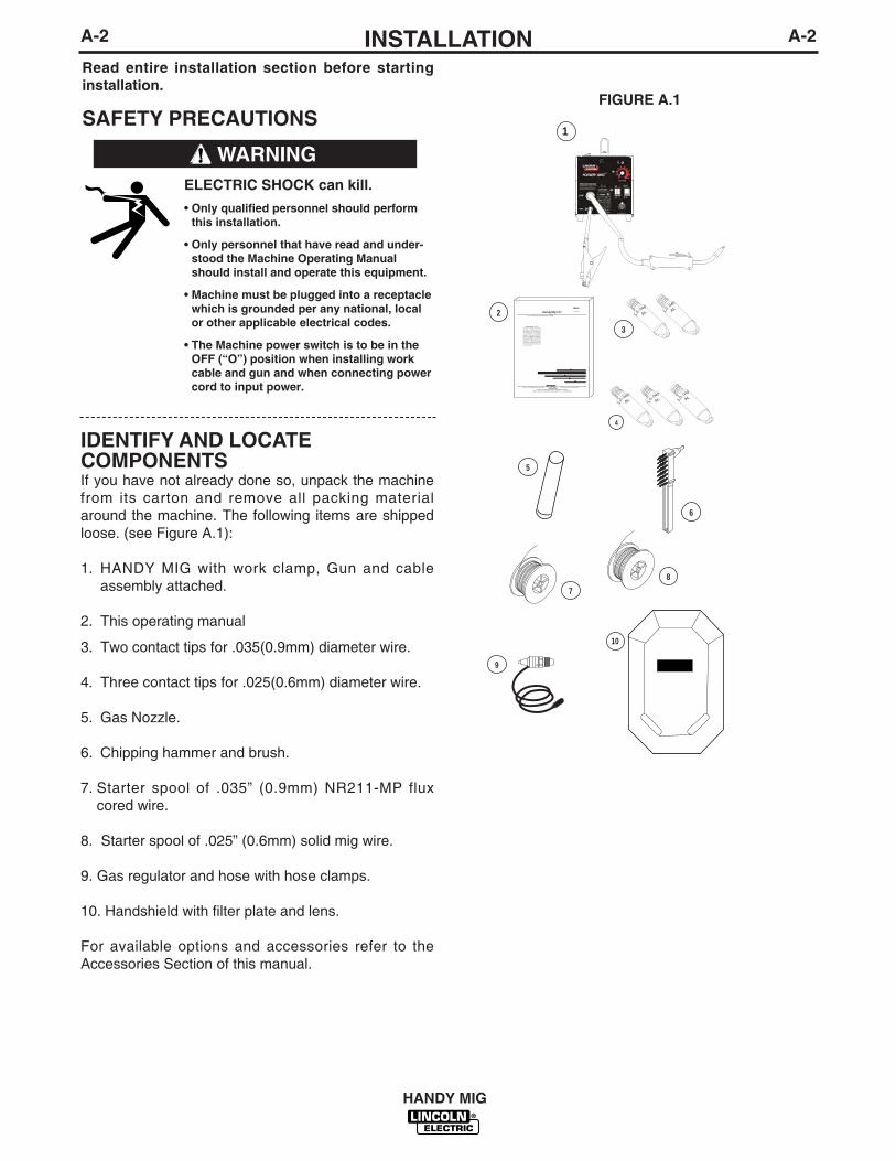
IDENTIFY AND LOCATE COMPONENTSIf you have not already done so, unpack the machinefrom its carton and remove all packing materialaround the machine. The following items are shippedloose. (see Figure A.1):
1. HANDY MIG with work clamp, Gun and cableassembly attached.
2. This operating manual
3. Two contact tips for .035(0.9mm) diameter wire.
4. Three contact tips for .025(0.6mm) diameter wire.
5. Gas Nozzle.
6. Chipping hammer and brush.
7. Starter spool of .035” (0.9mm) NR211-MP fluxcored wire.
8. Starter spool of .025” (0.6mm) solid mig wire.
9. Gas regulator and hose with hose clamps.
10. Handshield with filter plate and lens.
For available options and accessories refer to theAccessories Section of this manual.
ELECTRIC SHOCK can kill.
• Only qualified personnel should performthis installation.
• Only personnel that have read and under-stood the Machine Operating Manualshould install and operate this equipment.
• Machine must be plugged into a receptaclewhich is grounded per any national, localor other applicable electrical codes.
• The Machine power switch is to be in theOFF (“O”) position when installing workcable and gun and when connecting powercord to input power.
WARNING
FIGURE A.1
2
3
4
5
6
7
9
10
8
1.0-
.040
AL 1.0-
.040
AL
1.0-
.040
AL 1.0-
.040
AL 1.0-
.040
AL
Handy Mig 101IM000October 1998
For use with machines having Code Numbers: 00000
Safety Depends on YouLincoln arc welding and cuttingequipment is designed and builtwith safety in mind. However, youroverall safety can be increased byproper installation...and thoughtfuloperation on your part. DO NOTINSTALL, OPERATE OR REPAIRTHIS EQUIPMENT WITHOUTREADING THIS MANUALAND THES A F E T T P R E C A U T I O N SCONTAINED THROUGHOUT. And,most importantly, think before youact and be careful.
World's Leader in Welding and Cutting Products Premier Manufacturer of Industrial Motors
Sales and Service through Subsidiaries and Distributors Worldwide
22801 St. Clair Ave. Cleveland, ohio 44117-1199 U.S.A. Tel. (216) 481-8100
1
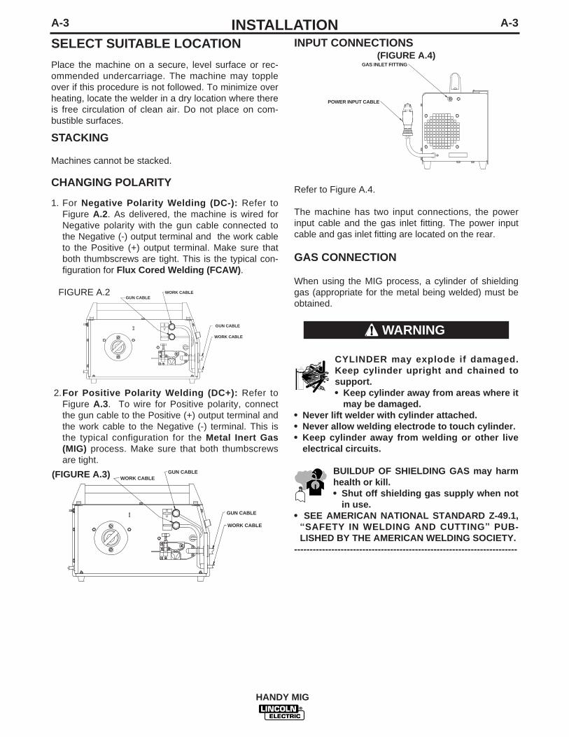
INPUT CONNECTIONS (FIGURE A.4)
Refer to Figure A.4.
The machine has two input connections, the powerinput cable and the gas inlet fitting. The power inputcable and gas inlet fitting are located on the rear.
GAS CONNECTION
When using the MIG process, a cylinder of shieldinggas (appropriate for the metal being welded) must beobtained.
CYLINDER may explode if damaged.Keep cylinder upright and chained tosupport.• Keep cylinder away from areas where it
may be damaged.• Never lift welder with cylinder attached.• Never allow welding electrode to touch cylinder.• Keep cylinder away from welding or other live
electrical circuits.
BUILDUP OF SHIELDING GAS may harmhealth or kill.• Shut off shielding gas supply when not
in use.• SEE AMERICAN NATIONAL STANDARD Z-49.1,
“SAFETY IN WELDING AND CUTTING” PUB-LISHED BY THE AMERICAN WELDING SOCIETY.
------------------------------------------------------------------------
GAS INLET FITTING
POWER INPUT CABLE
A-3INSTALLATION
HANDY MIG
A-3
SELECT SUITABLE LOCATION
Place the machine on a secure, level surface or rec-ommended undercarriage. The machine may toppleover if this procedure is not followed. To minimize overheating, locate the welder in a dry location where thereis free circulation of clean air. Do not place on com-bustible surfaces.
STACKING
Machines cannot be stacked.
CHANGING POLARITY
1. For Negative Polarity Welding (DC-): Refer toFigure A.2. As delivered, the machine is wired forNegative polarity with the gun cable connected tothe Negative (-) output terminal and the work cableto the Positive (+) output terminal. Make sure thatboth thumbscrews are tight. This is the typical con-figuration for Flux Cored Welding (FCAW).
2.For Positive Polarity Welding (DC+): Refer toFigure A.3. To wire for Positive polarity, connectthe gun cable to the Positive (+) output terminal andthe work cable to the Negative (-) terminal. This isthe typical configuration for the Metal Inert Gas(MIG) process. Make sure that both thumbscrewsare tight.
WARNING
WORK CABLE
WORK CABLE
WORK CABLE
WORK CABLE
GUN CABLE
GUN CABLE
GUN CABLE
GUN CABLE
(FIGURE A.3)
WORK CABLE
WORK CABLE
WORK CABLE
WORK CABLE
GUN CABLE
GUN CABLE
GUN CABLE
GUN CABLE
FIGURE A.2
A-4INSTALLATION
HANDY MIG
A-4
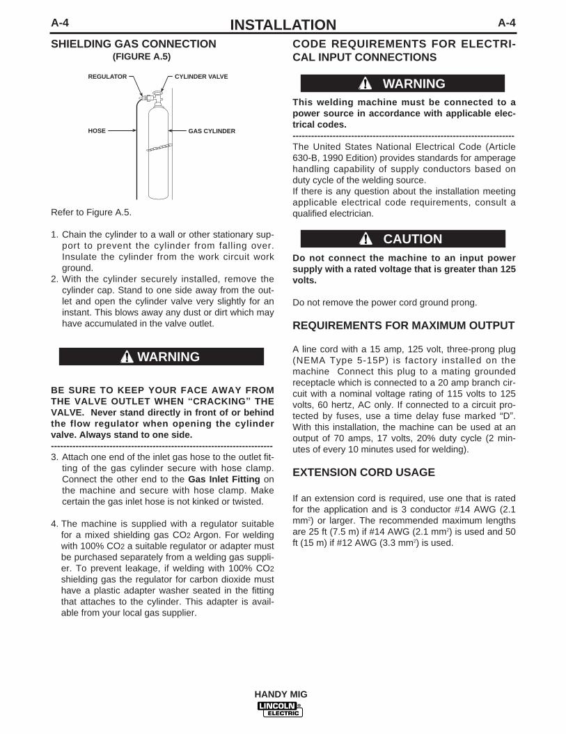
SHIELDING GAS CONNECTION(FIGURE A.5)
Refer to Figure A.5.
1. Chain the cylinder to a wall or other stationary sup-port to prevent the cylinder from falling over.Insulate the cylinder from the work circuit workground.
2. With the cylinder securely installed, remove thecylinder cap. Stand to one side away from the out-let and open the cylinder valve very slightly for aninstant. This blows away any dust or dirt which mayhave accumulated in the valve outlet.
BE SURE TO KEEP YOUR FACE AWAY FROMTHE VALVE OUTLET WHEN “CRACKING” THEVALVE. Never stand directly in front of or behindthe flow regulator when opening the cylindervalve. Always stand to one side.------------------------------------------------------------------------3. Attach one end of the inlet gas hose to the outlet fit-
ting of the gas cylinder secure with hose clamp.Connect the other end to the Gas Inlet Fitting onthe machine and secure with hose clamp. Makecertain the gas inlet hose is not kinked or twisted.
4. The machine is supplied with a regulator suitablefor a mixed shielding gas CO2 Argon. For weldingwith 100% CO2 a suitable regulator or adapter mustbe purchased separately from a welding gas suppli-er. To prevent leakage, if welding with 100% CO2
shielding gas the regulator for carbon dioxide musthave a plastic adapter washer seated in the fittingthat attaches to the cylinder. This adapter is avail-able from your local gas supplier.
WARNING
CYLINDER VALVE
GAS CYLINDER
REGULATOR
HOSE
CODE REQUIREMENTS FOR ELECTRI-CAL INPUT CONNECTIONS
This welding machine must be connected to apower source in accordance with applicable elec-trical codes.------------------------------------------------------------------------The United States National Electrical Code (Article630-B, 1990 Edition) provides standards for amperagehandling capability of supply conductors based onduty cycle of the welding source.If there is any question about the installation meetingapplicable electrical code requirements, consult aqualified electrician.
Do not connect the machine to an input powersupply with a rated voltage that is greater than 125volts.
Do not remove the power cord ground prong.
REQUIREMENTS FOR MAXIMUM OUTPUT
A line cord with a 15 amp, 125 volt, three-prong plug(NEMA Type 5-15P) is factory installed on themachine Connect this plug to a mating groundedreceptacle which is connected to a 20 amp branch cir-cuit with a nominal voltage rating of 115 volts to 125volts, 60 hertz, AC only. If connected to a circuit pro-tected by fuses, use a time delay fuse marked “D”.With this installation, the machine can be used at anoutput of 70 amps, 17 volts, 20% duty cycle (2 min-utes of every 10 minutes used for welding).
EXTENSION CORD USAGE
If an extension cord is required, use one that is ratedfor the application and is 3 conductor #14 AWG (2.1mm2) or larger. The recommended maximum lengthsare 25 ft (7.5 m) if #14 AWG (2.1 mm2) is used and 50ft (15 m) if #12 AWG (3.3 mm2) is used.
WARNING
CAUTION

B-1OPERATIONB-1
HANDY MIG
Read entire operation section beforeoperating the machine.
ELECTRIC SHOCK can kill.• Do not touch electrically live
parts or electrode with skin orwet clothing. Insulate yourselffrom work and ground.
• Always wear dry insulatinggloves.
FUMES AND GASES can bedangerous.• Keep your head out of fumes.
• Use ventilation or exhaust toremove fumes from breathingzone.
WELDING SPARKS cancause fire or explosion.• Keep flammable material away.
• Do not weld on closed contain-ers.
ARC RAYS can burn eyesand skin.• Wear eye, ear and body protec-
tion.
Observe all safety information throughoutthis manual.
WARNING
GENERAL DESCRIPTION
The machine is a semiautomatic constant voltage DCarc welder. The machine uses a single phase con-stant voltage transformer, solid state rectifier and aDC permanent magnet motor for feeding and weldingsolid steel electrode and flux-cored electrode.The machine is ideally suited for individuals havingaccess to 115 volt AC input power and wanting theease of use, quality and dependability of both metalinert gas (MIG) welding and the Innershield electrodeprocess (self-shielded flux-cored welding). Themachine will handle reels of wire up to 2 lbs(1 kg).
RECOMMENDED PROCESSES
The machine can be used for welding carbon and low-alloy steel with CO2 or argon/CO2 mixture shielding
gas. The welder can also be used without gas for theself-shielded, Innershield electrode process. Themachine is configured for the Flux Cored Arc Weldingprocess as delivered from the factory.
OPERATIONAL FEATURES AND CONTROLS
The machine has the following controls as standard:• Power ON/OFF Switch• Heat Range Switch• 1 – 2 Fine Heat Adjustment Switch• Wire Speed Control
DESIGN FEATURES AND ADVANTAGES
• Operates on 115 volt input - no special wiringrequired.
• Solid state output control.• Overload protection - incorporates a thermostat to
protect the welder from overheating caused by mal-functions or overly heavy use.
• Permanent magnet wire drive motor.• Easy-to-set controls for arc voltage and wire speed.• Thumbscrew release idle roll pressure arm is easily
adjusted.• Reversible, dual groove drive roll will feed .023-
.035” (0.6- 0.9 mm) diameter wire.• Accommodates spools of wire up to 2 lbs(1 kg) in
weight.• No external shielding gas is required when used
with Lincoln Innershield .035” (0.9 mm) NR®-211-MP electrode.
• Easy to change polarity.

B-2OPERATIONB-2
TABLE B.1 – MIG WELDING MATERIAL/GAS COMBINATIONS
Material GasCarbon Steel CO2 or Argon/CO2
Low Alloy Steel CO2 or Argon/CO2
FLUX-CORED (INNERSHIELD) WELDINGThe recommended electrode for the flux-cored, self-shielded process is 0.035” (0.9 mm) diameter LincolnInnershield NR-211-MP on 2 lbs. (.9 kg) spools.
SEQUENCE OF OPERATIONSWIRE LOADING AND THREADING
Refer to Figure B.2.
Turn machine power switch to the OFF (“0”) positionbefore working inside the wire feed enclosure.Make sure that the wire feed drive roll and the contacttip of the gun match the diameter and type of wireused.
1. Push the spool onto the spindle so that the wirefeeds off the bottom of the spool, toward the driveroll.
2. Push the spool spacer onto the spindle, against thespool.
3. Slide the spring onto the spool, then press on thespool lock, turning it clockwise to lock the spoolassembly onto the spindle.
WELDING CAPABILITYThe machine is rated at 70 amps, 17 volts, at 20%duty cycle on a ten minute basis. It is capable of high-er output currents at lower duty cycles.
LIMITATIONSThe machine is recommended for welding on mildsteel up to 1/8” thick.
CONTROLS AND SETTINGS
Refer to Figure B.1.
1. Power ON/OFF Switch -When the power is ONthe welding output and wire feeder are ON (“hot”)when the gun trigger is pressed.
2. Low / High Heat Range Switch. -A rocker switchcontrol that gives low or high coarse range adjust-ment of the power source output voltage.
3. 1 – 2 Fine Heat Adjustment Switch. -Allows fineadjustment of the voltage within the selected Lowor High output range.
4. Wire Speed Control. -Controls the wire feedspeed. Wire speed is not affected when changesare made in the voltage control.
WELDING OPERATIONS
PROCESS GUIDELINES
MIG WELDING
Table B.1 shows the recommended material/gascombinations for MIG welding with solid electrodes.
HANDY MIG
1
4
2
3
FIGURE B.1
SPINDLE
SPRING
SPOOLLOCK
SPOOLSPACER
SPOOL
FIGURE B.2

B-3OPERATIONB-3
FIGURE B.3 – WIRE THREADING DETAILS
Refer to Figure B.3.4. Release the spring loaded thumbscrew and lift up
the idle roll arm away from the wire feed drive roll.Ensure that the visible, stenciled size on the driveroll side facing you matches the wire size beingused.
5. Carefully detach the end of the wire from the spoolmaintain tension on the wire. To prevent the spoolfrom unwinding and do not release the wire untilafter step 8.
6. Cut the bent portion of wire off and straighten thefirst 4” (100 mm).
7. Thread the wire through the ingoing guide tube,over the drive roll, and into the gun liner.
8. Close the idle roll arm and turn down the thumb-screw until the idle roller presses down firmly on thewire. (Now you may release the welding wire).Make sure the wire is positioned in the groove ofthe lower drive roll.
9. The spring loaded thumbscrew on the idle roll armadjusts the pressure on the wire. Adjust pressureby turning the thumbscrew to prevent spool over-run, but still allow smooth and easy wire feeding.Start with the pressure set to an intermediate value.Readjust, if necessary. Slightly less pressure maybe required when using 0.023 - 0.025” (0.6 mm)wire. If the drive roll slips while feeding wire, thepressure should be increased until the wire feedsproperly.
• When feeding the welding wirethrough the gun, the drive roll, thegun connector block and the guncontact tip are always energized rela-tive to work and ground.
FIGURE B.4 – WIRE STICKOUT
10. Remove the gas nozzle and contact tip from thegun.
11. Turn the machine ON (“I”).12. Straighten the gun cable assembly.13. Depress the gun trigger switch and feed welding
wire through the gun and cable. (Point the gunaway from yourself and others while feeding wire.)Release the gun trigger after wire appears at theend of the gun.
14. Turn off the machine. 15. Replace the contact tip. Refer to Figure B-4. Cut
the wire off so that 3/8” to 5/8” (10 - 15 mm) pro-trudes from the end of the tip.
16. Turn on the machine. The machine is now readyto weld.
SHIELDING GASWhen using the MIG process, you will need a cylinderof carbon dioxide (CO2) or argon-carbon dioxidemixed shielding gas.
The preset regulator supplied with the machine isdesigned for use with argon blend gas. An adapterand plastic washer are needed for using 100% CO2gas. This adapter is available from your local gas sup-plier.
1. Open the cylinder valve slowly a fraction of a turn.When the cylinder pressure gauge pointer stopsmoving, open the valve fully.
2. Keep the cylinder valve closed, except when weld-ing. When finished welding:• Close the cylinder valve to stop gas flow.• Depress the gun trigger briefly to release the
pressure in the gas hose.• Turn off the machine.
HANDY MIG
Spring Loaded Thumb Screw
Ingoing Guide Tube
Wire
Wire FeedLower Drive Roll
UpperIdler Roll Arm
CONTACT TIP
WIREELECTRODE
3/8"Contact Tip To WorkDistance (CTWD)
WARNING

B-4OPERATIONB-4
MAKING A WELDFIGURE B.5 – WELDING SETUP
READ the LEARNING TO WELD (LTW1) manualprior to making your first weld. Also, refer to TableB.1 and the Procedure Decal located on the inside ofthe wire drive compartment door of your machine forprocess selection, consumables, and quick tips forwelding.
1. Select the right welding process based on the typeand condition of the pieces to be welded; the envi-ronment in which welding is to be done; and thedesired finished appearance of the weld.
2. Select and install the welding wire to match theprocess. Use Genuine Lincoln Electric Brand wire.Wire quality is essential for successful welding.
3. Install the drive roll, contact tip, and nozzle appro-priate for the weld process.
HANDY MIG
WORKPIECE
GUN CABLE
ARC
WORK CLAMP
4. Check that the polarity is correct for the welding wirebeing used and that the gas supply, if required, isturned on.
5. Refer to Figure B.5. Connect the work clamp to themetal to be welded. The work clamp must makegood electrical contact to the work piece. The workpiece must also be grounded as stated in ArcWelding Safety Precautions in the beginning of thismanual.
6. Based on the welding process type and materialthickness of the work piece, use the chart below (oron the procedure decal located on the wire drivedoor) to set the correct wire feed speed and heatrange setting.
7. Based on the weld joint type and orientation of theweld joint, position the gun into the joint at the cor-rect angle. Refer to the LEARNING TOWELD(LTW1) manual.
8. To begin welding, raise your hand shield to protectyour eyes and pull the trigger.
9. While welding, travel at a constant speed and main-tain an electrode stickout of 3/8". Follow the correctdirection of travel for the process and joint type andorientation as detailed in the LEARNING TO WELD(LTW1) manual.
10. To stop welding, release the gun trigger.11. When no more welding is to be done, close the
valve on the gas cylinder (if used), momentarilyoperate the gun trigger to release gas pressure,and turn off the machine.
1
1
2
3
4
5
6
7 87 7
8 8
TABLE B.1

B-5OPERATIONB-5
HANDY MIG
CLEANING TIP AND GAS NOZZLE
Clean the contact tip and gas nozzle to avoid arcbridging between them. Bridging can result in a short-ed nozzle, poor welds and an overheated gun. Hint:Anti-stick spray or gel, available from a welding supplydistributor, may reduce buildup and aid in spatterremoval.
CHANGING MACHINE OVER TO FEEDOTHER WIRE SIZES
The machine is shipped from the factory ready to feed0.035” (0.9 mm) diameter wire. To operate themachine with other sizes of wire, it is necessary tochange the contact tip and change the drive roll toother sizes. Refer to Changing the Contact Tip andChanging the Drive Roll in the MAINTENANCE sec-tion for specific information on these procedures.
OVERLOAD PROTECTION
THERMAL PROTECTION
The machine has a maximum output duty cycle of20%. If the duty cycle is exceeded, a thermal protectorwill shut off the output until the machine cools to anormal operating temperature. This is an automaticfunction of the machine and does not require userintervention.
C-1ACCESSORIESC-1
ACCESSORIES
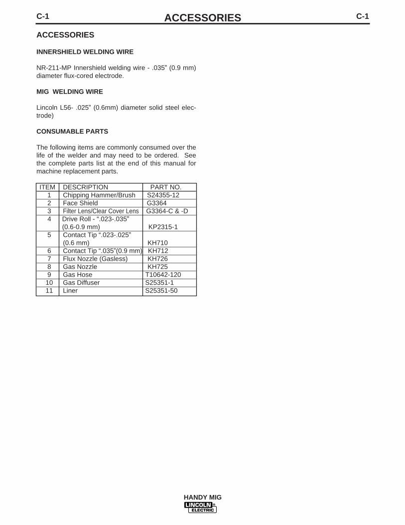
INNERSHIELD WELDING WIRE
NR-211-MP Innershield welding wire - .035” (0.9 mm)diameter flux-cored electrode.
MIG WELDING WIRE
Lincoln L56- .025” (0.6mm) diameter solid steel elec-trode)
CONSUMABLE PARTS
The following items are commonly consumed over thelife of the welder and may need to be ordered. Seethe complete parts list at the end of this manual formachine replacement parts.
ITEM DESCRIPTION PART NO.1 Chipping Hammer/Brush S24355-122 Face Shield G33643 Filter Lens/Clear Cover Lens G3364-C & -D4 Drive Roll - “.023-.035”
(0.6-0.9 mm) KP2315-15 Contact Tip “.023-.025”
(0.6 mm) KH7106 Contact Tip “.035”(0.9 mm) KH7127 Flux Nozzle (Gasless) KH7268 Gas Nozzle KH7259 Gas Hose T10642-12010 Gas Diffuser S25351-111 Liner S25351-50
HANDY MIG
MAINTENANCE
SAFETY PRECAUTIONS
ELECTRIC SHOCK can kill.
• Disconnect input power by removingplug from receptacle before workinginside machine. Use only groundedreceptacle. Do not touch electrically“hot” parts inside machine
• Have qualified personnel do the mainte-nance and trouble shooting work.
ITEMS REQUIRINGNO MAINTENANCE
• Drive Motor and Gearbox – Lifetime lubrication
• Wire Reel Spindle – Do NOT lubricate shaft
ROUTINE AND PERIODICMAINTENANCE
BEFORE EACH USE
• Check over machine and accessories for any obvious condi-tion that may prevent safe performance or operation. Repairor replace items as necessary to correct any abnormal con-dition.
AFTER 5 MINUTES OF WELDING
or when spatter accumulates in the gas nozzle:
• Clean the contact tip and gas nozzle to avoid bridgingbetween the nozzle and contact tip. Bridging results in ashorted nozzle, poor welds and overheated gun. Hint: Anti-stick spray or gel available from a welding supply distributormay reduce buildup and aid in spatter removal.
D-1MAINTENANCED-1
HANDY MIG
WARNING
D-2MAINTENANCED-2
HANDY MIG
CLEANING THE GUN LINER
• Unplug the machine or turn the power switch to theOFF - “0” position.
• Remove the gas nozzle and contact tip from thegun.
• Clean the inside diameter with a short piece of wire.
• Clean the cable liner when rough and erratic wirefeeding occur:
Lay the cable out straight. Blow out gently with drycompressed air (max 145 psi) through the wire guidetube and check the condition of the tube. Bend thecable back and forth, then blow the tube out again.Repeat until clean.
Excessive pressure at start may cause the dirt toform a plug.------------------------------------------------------------------------CLEANING COMPONENTS AS REQUIRED
• Unplug the machine or turn the power switch to theOFF - “0” position.
• Blow dirt out of the welder with low pressure air toeliminate excessive dirt and dust buildup that couldcause the welder to run hot.
• Vacuum accumulated dirt from the gear-box andwire feed section.
• Inspect the incoming guide tube and clean theinside diameter if necessary. Replace when exces-sively worn.
• Replace Contact Tip - when the hole is enlarged orelongated. (Refer to Changing The Contact Tip, inthis section.)
• Check the condition of the wire feed rollers.Remove any metallic dust deposited in the feedarea (rollers and entrance and outlet wire guide).
• Check the gas hose and fittings for tightness.
COMPONENT REPLACEMENT PROCEDURES
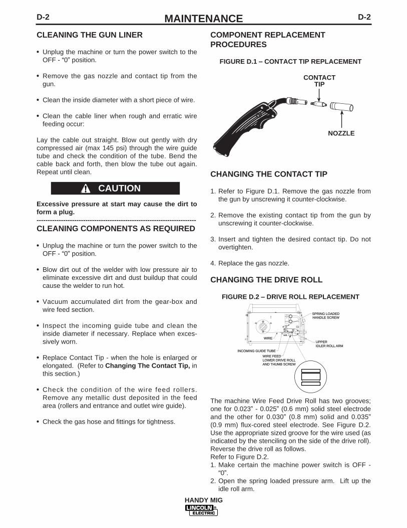
FIGURE D.1 – CONTACT TIP REPLACEMENT
CHANGING THE CONTACT TIP
1. Refer to Figure D.1. Remove the gas nozzle fromthe gun by unscrewing it counter-clockwise.
2. Remove the existing contact tip from the gun byunscrewing it counter-clockwise.
3. Insert and tighten the desired contact tip. Do notovertighten.
4. Replace the gas nozzle.
CHANGING THE DRIVE ROLL
FIGURE D.2 – DRIVE ROLL REPLACEMENT
The machine Wire Feed Drive Roll has two grooves;one for 0.023” - 0.025” (0.6 mm) solid steel electrodeand the other for 0.030” (0.8 mm) solid and 0.035”(0.9 mm) flux-cored steel electrode. See Figure D.2.Use the appropriate sized groove for the wire used (asindicated by the stenciling on the side of the drive roll).Reverse the drive roll as follows. Refer to Figure D.2.1. Make certain the machine power switch is OFF -
“0”.2. Open the spring loaded pressure arm. Lift up the
idle roll arm.
CAUTION
NOZZLE
CONTACT TIP
EN50078 1.0-.0
40AL
HHANDLE SCREW
UPPERIDLER ROLL ARM
WIRE FEEDLOWER DRIVE ROLLAND THUMB SCREW
INCOMING GUIDE TUBE
WIRE
SPRING LOADED

D-3MAINTENANCED-3
HANDY MIG
3. Remove the Thumbscrew holding the drive roll. 4. Replace the drive roll so that the desired size, sten-
ciled on the side of the drive roll, is toward theinside and visible.
5. Replace the Thumbscrew and tighten.
GUN ASSEMBLY REMOVAL
1. Unplug machine and disconnect gas supply.2. Remove wire drive door and left case side.3. Remove trigger leads. the trigger leads are routed
through the center panel and connected to the P.C.board (3/1,3/2). Use care in removal as not to dam-age the P.C. board or adjoining leads.
4. Remove gas line connections.5. Remove gun connections from output studs.6. Disconnect the gun liner from the wire drive.
Remove nut and spacer and slide liner back andout.
7. Installation is the reverse of removal. (7 thru 1)
WORK CABLE INSTALLATION
The work cable and clamp comes already installed. Ifyou should ever need to replace or reinstall the cable,do the following. Refer to Figure D.3.
1. Remove the case sides.
2. Pass the end of the work cable with the terminal lugthrough the Work Cable Access Hole in the casefront.
3. Route the cable as detailed in the picture. The workcable should be routed between the metal dividerpanel and the wire feed gear box and gun assem-bly.
WORK CABLE AND GROMMET
FIGURE D.3
E-1TROUBLESHOOTINGE-1
HANDY MIG
If for any reason you do not understand the test procedures or are unable to perform the tests/repairs safely, contact yourLocal Lincoln Authorized Field Service Facility for technical troubleshooting assistance before you proceed.
CAUTION
This Troubleshooting Guide is provided to help youlocate and repair possible machine malfunctions.Simply follow the three-step procedure listed below.
Step 1. LOCATE PROBLEM (SYMPTOM).Look under the column labeled “PROBLEM (SYMP-TOMS)”. This column describes possible symptomsthat the machine may exhibit. Find the listing thatbest describes the symptom that the machine isexhibiting.
Step 2. POSSIBLE CAUSE.The second column labeled “POSSIBLE CAUSE” liststhe obvious external possibilities that may contributeto the machine symptom.
Step 3. RECOMMENDED COURSE OF ACTIONThis column provides a course of action for thePossible Cause, generally it states to contact yourlocal Lincoln Authorized Field Service Facility.
If you do not understand or are unable to perform theRecommended Course of Action safely, contact yourlocal Lincoln Authorized Field Service Facility.
HOW TO USE TROUBLESHOOTING GUIDE
Service and Repair should only be performed by Lincoln Electric Factory Trained Personnel.Unauthorized repairs performed on this equipment may result in danger to the technician andmachine operator and will invalidate your factory warranty. For your safety and to avoid ElectricalShock, please observe all safety notes and precautions detailed throughout this manual.
__________________________________________________________________________
WARNING

E-2TROUBLESHOOTINGE-2
HANDY MIG
If for any reason you do not understand the test procedures or are unable to perform the tests/repairs safely, contact yourLocal Lincoln Authorized Field Service Facility for technical troubleshooting assistance before you proceed.
CAUTION
PROBLEMS(SYMPTOMS)
Major physical or electrical damageis evident.
No wire feed, weld output or gasflow when gun trigger is pulled.
No weld output when gun trigger ispulled.
POSSIBLECAUSE
NoneContact your local Authorized FieldService Facility.
1. Make sure correct voltage isapplied to the machine (115vac).
2. Make certain that power switchis in the ON position.
3. The thermostat may be trippeddue to overheating. Let machinecool. Weld within the duty cycleor remove any air obstruction tothe machine.
1. Gun tip may be worn. Replace.
2. Gun trigger may be faulty.
3. The gun or work cable may befaulty.
RECOMMENDEDCOURSE OF ACTION
If all recommended possible areasof misadjustment have beenchecked and the problem persists,Contact your local LincolnAuthorized Field ServiceFacility.
OUTPUT PROBLEMS
Observe all Safety Guidelines detailed throughout this manual

E-3TROUBLESHOOTINGE-3
HANDY MIG
If for any reason you do not understand the test procedures or are unable to perform the tests/repairs safely, contact yourLocal Lincoln Authorized Field Service Facility for technical troubleshooting assistance before you proceed.
CAUTION
PROBLEMS(SYMPTOMS)
No wire feed when gun trigger ispulled.
POSSIBLECAUSE
1. The thermostat may be trippeddue to overheating. Let machinecool. Weld within the duty cycleor remove any air obstruction tothe machine.
2. Gun trigger may be faulty.
3. Drive Roll tension is set too high.
4. Wire may be kinked or jammed.Inspect Drive Roll and GuideTubes.
RECOMMENDEDCOURSE OF ACTION
If all recommended possible areasof misadjustment have beenchecked and the problem persists,Contact your local LincolnAuthorized Field ServiceFacility.
FEEDING PROBLEMS
Observe all Safety Guidelines detailed throughout this manual
E-4TROUBLESHOOTINGE-4
HANDY MIG
If for any reason you do not understand the test procedures or are unable to perform the tests/repairs safely, contact yourLocal Lincoln Authorized Field Service Facility for technical troubleshooting assistance before you proceed.
CAUTION
PROBLEMS(SYMPTOMS)
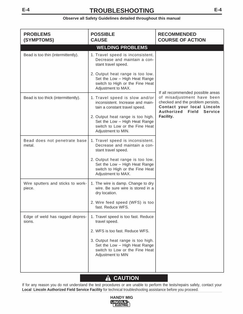
Bead is too thin (intermittently).
Bead is too thick (intermittently).
Bead does not penetrate basemetal.
Wire sputters and sticks to work-piece.
Edge of weld has ragged depres-sions.
POSSIBLECAUSE
1. Travel speed is inconsistent.Decrease and maintain a con-stant travel speed.
2. Output heat range is too low.Set the Low – High Heat Rangeswitch to High or the Fine HeatAdjustment to MAX.
1. Travel speed is slow and/orinconsistent. Increase and main-tain a constant travel speed.
2. Output heat range is too high.Set the Low – High Heat Rangeswitch to Low or the Fine HeatAdjustment to MIN.
1. Travel speed is inconsistent.Decrease and maintain a con-stant travel speed.
2. Output heat range is too low.Set the Low – High Heat Rangeswitch to High or the Fine HeatAdjustment to MAX.
1. The wire is damp. Change to drywire. Be sure wire is stored in adry location.
2. Wire feed speed (WFS) is toofast. Reduce WFS.
1. Travel speed is too fast. Reducetravel speed.
2. WFS is too fast. Reduce WFS.
3. Output heat range is too high.Set the Low – High Heat Rangeswitch to Low or the Fine HeatAdjustment to MIN
RECOMMENDEDCOURSE OF ACTION
If all recommended possible areasof misadjustment have beenchecked and the problem persists,Contact your local LincolnAuthorized Field ServiceFacility.
WELDING PROBLEMS
Observe all Safety Guidelines detailed throughout this manual
F-1DIAGRAMSF-1
HANDY MIG
X4/1
S114
54
4
25
3 6S2
1
2
M1
2 3
T1
g
H2
V
KA2
64
222
A11
35
21
X4/2
X62 1
X51 2
X7X1X2
L
M2redbla
ck
3 2X8
X1/1
X1/2
2
1X2
X3/2
X3/1
X1/3
R1
1PL
UG 11
5V
WELD
ERIN
PUT
CABL
E
W B G
0I
g
X1 X2X2 X1NO
GAS
GAS
GREE
N LEA
D
HA
ND
Y M
IG W
IRIN
G D
IAG
RA
M F
OR
CO
DE
1091
9 M19
903
A
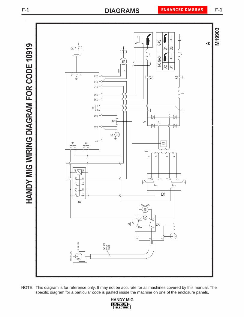
NOTE: This diagram is for reference only. It may not be accurate for all machines covered by this manual. Thespecific diagram for a particular code is pasted inside the machine on one of the enclosure panels.
F-2DIAGRAMSF-2
HANDY MIG
M20
242
A
WIR
ING
DIA
GR
AM F
OR
CO
DE
1120
5
WE
LDER
LDER
INPU
TPU
TC
AC
ABLBLE
S114
25
M1
W B G
0I
GR
EEN
LE
GR
EEN
LEADAD PL
UG
PLU
G
3 61
22 3
T1
S2
54
4
Vg
g
L
M2
red
blac
kbl
ack
X1 X2 X3
X5
X4
X8
X11
X10
X9
X2X2 X1X1
X2X2 X1X1NO G
NO G
ASGA
S
X2X2X1X1
X7
X6
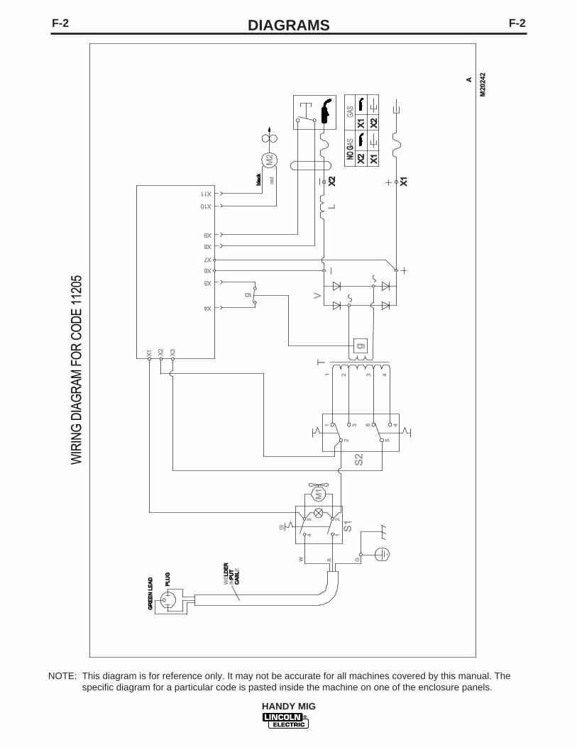
NOTE: This diagram is for reference only. It may not be accurate for all machines covered by this manual. Thespecific diagram for a particular code is pasted inside the machine on one of the enclosure panels.
HANDY MIG
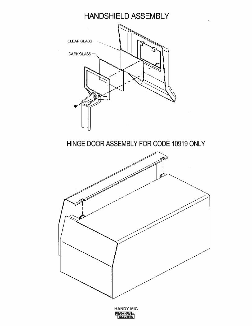
HINGE DOOR ASSEMBLY FOR CODE 10919 ONLY

NOTES
HANDY MIG

NOTES
HANDY MIG
WARNING
AVISO DEPRECAUCION
ATTENTION
WARNUNG
ATENÇÃO
Spanish
French
German
Portuguese
Japanese
Chinese
Korean
Arabic
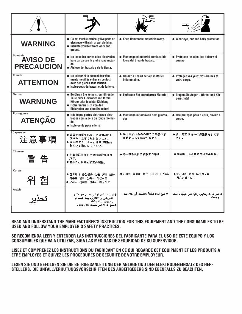
READ AND UNDERSTAND THE MANUFACTURER’S INSTRUCTION FOR THIS EQUIPMENT AND THE CONSUMABLES TO BEUSED AND FOLLOW YOUR EMPLOYER’S SAFETY PRACTICES.
SE RECOMIENDA LEER Y ENTENDER LAS INSTRUCCIONES DEL FABRICANTE PARA EL USO DE ESTE EQUIPO Y LOSCONSUMIBLES QUE VA A UTILIZAR, SIGA LAS MEDIDAS DE SEGURIDAD DE SU SUPERVISOR.
LISEZ ET COMPRENEZ LES INSTRUCTIONS DU FABRICANT EN CE QUI REGARDE CET EQUIPMENT ET LES PRODUITS AETRE EMPLOYES ET SUIVEZ LES PROCEDURES DE SECURITE DE VOTRE EMPLOYEUR.
LESEN SIE UND BEFOLGEN SIE DIE BETRIEBSANLEITUNG DER ANLAGE UND DEN ELEKTRODENEINSATZ DES HER-STELLERS. DIE UNFALLVERHÜTUNGSVORSCHRIFTEN DES ARBEITGEBERS SIND EBENFALLS ZU BEACHTEN.
● Do not touch electrically live parts orelectrode with skin or wet clothing.
● Insulate yourself from work andground.
● No toque las partes o los electrodosbajo carga con la piel o ropa moja-da.
● Aislese del trabajo y de la tierra.
● Ne laissez ni la peau ni des vête-ments mouillés entrer en contactavec des pièces sous tension.
● Isolez-vous du travail et de la terre.
● Berühren Sie keine stromführendenTeile oder Elektroden mit IhremKörper oder feuchter Kleidung!
● Isolieren Sie sich von denElektroden und dem Erdboden!
● Não toque partes elétricas e elec-trodos com a pele ou roupa molha-da.
● Isole-se da peça e terra.
● Keep flammable materials away.
● Mantenga el material combustiblefuera del área de trabajo.
● Gardez à l’écart de tout matérielinflammable.
● Entfernen Sie brennbarres Material!
● Mantenha inflamáveis bem guarda-dos.
● Wear eye, ear and body protection.
● Protéjase los ojos, los oídos y elcuerpo.
● Protégez vos yeux, vos oreilles etvotre corps.
● Tragen Sie Augen-, Ohren- und Kör-perschutz!
● Use proteção para a vista, ouvido ecorpo.
WARNING
AVISO DEPRECAUCION
ATTENTION
WARNUNG
ATENÇÃO
Spanish
French
German
Portuguese
Japanese
Chinese
Korean
Arabic
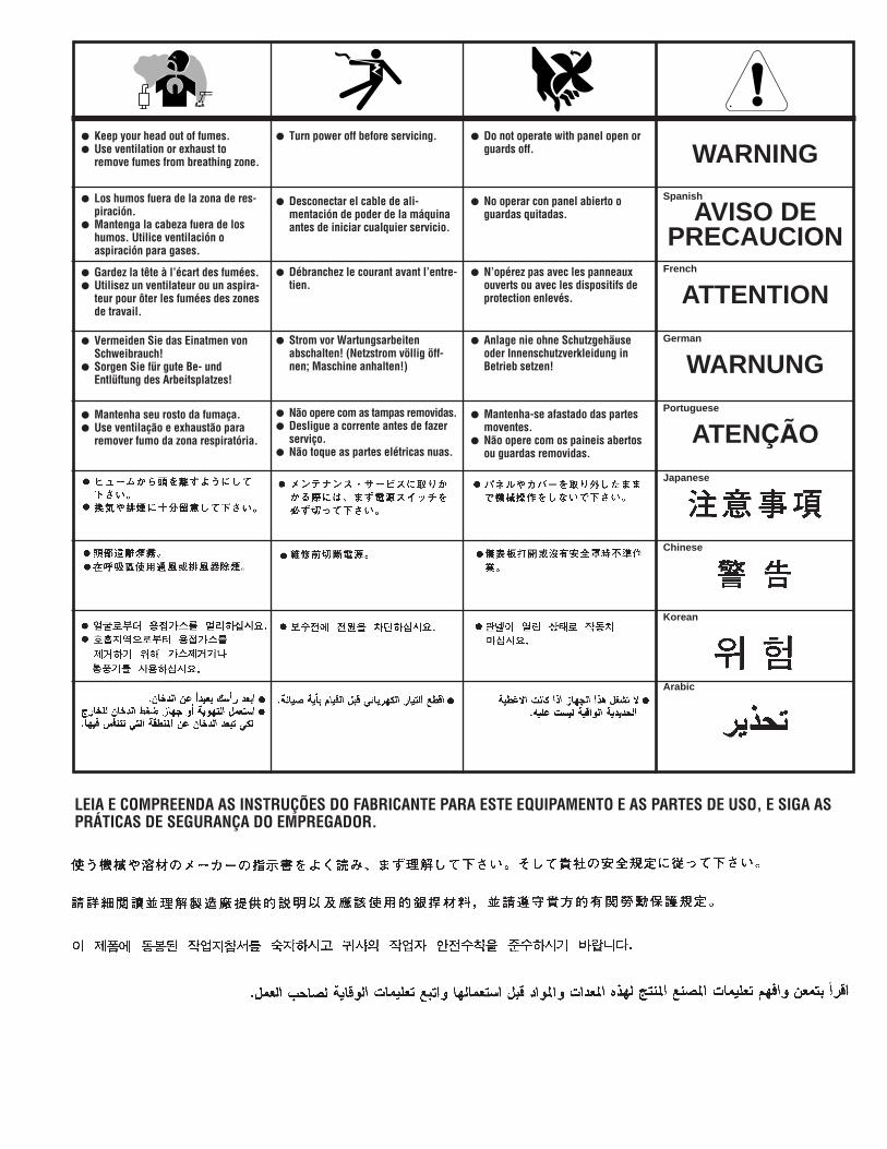
LEIA E COMPREENDA AS INSTRUÇÕES DO FABRICANTE PARA ESTE EQUIPAMENTO E AS PARTES DE USO, E SIGA ASPRÁTICAS DE SEGURANÇA DO EMPREGADOR.
● Keep your head out of fumes.● Use ventilation or exhaust to
remove fumes from breathing zone.
● Los humos fuera de la zona de res-piración.
● Mantenga la cabeza fuera de loshumos. Utilice ventilación oaspiración para gases.
● Gardez la tête à l’écart des fumées.● Utilisez un ventilateur ou un aspira-
teur pour ôter les fumées des zonesde travail.
● Vermeiden Sie das Einatmen vonSchweibrauch!
● Sorgen Sie für gute Be- undEntlüftung des Arbeitsplatzes!
● Mantenha seu rosto da fumaça.● Use ventilação e exhaustão para
remover fumo da zona respiratória.
● Turn power off before servicing.
● Desconectar el cable de ali-mentación de poder de la máquinaantes de iniciar cualquier servicio.
● Débranchez le courant avant l’entre-tien.
● Strom vor Wartungsarbeitenabschalten! (Netzstrom völlig öff-nen; Maschine anhalten!)
● Não opere com as tampas removidas.● Desligue a corrente antes de fazer
serviço.● Não toque as partes elétricas nuas.
● Do not operate with panel open orguards off.
● No operar con panel abierto oguardas quitadas.
● N’opérez pas avec les panneauxouverts ou avec les dispositifs deprotection enlevés.
● Anlage nie ohne Schutzgehäuseoder Innenschutzverkleidung inBetrieb setzen!
● Mantenha-se afastado das partesmoventes.
● Não opere com os paineis abertosou guardas removidas.

• Sales and Service through Subsidiaries and Distributors Worldwide •
Cleveland, Ohio 44117-1199 U.S.A. TEL: 216.481.8100 FAX: 216.486.1751 WEB SITE: www.lincolnelectric.com
• World's Leader in Welding and Cutting Products •