Embed Size (px)
Citation preview
. . . . . . . . . . . . . . . . . . . . . . . . . . . . . . . . . . . . . . . . . . . . . . . . .
Cheetah 18XL Family:. . . . . . . . . . . . . . . . . . . . . . . . . . . . . . . . . . . . . . . . . . . . . . . . .
ST318404LW/LC. . . . . . . . . . . . . . . . . . . . . . . . . . . . . . . . . . . . . . . . . . . . . . . . .
ST39204LW/LC. . . . . . . . . . . . . . . . . . . . . . . . . . . . . . . . . . . . . . . . . . . . . . . . .
. . . . . . . . . . . . . . . . . . . . . . . . . . . . . . . . . . . . . . . . . . . . . . . . .
Product Manual, Volume 1. . . . . . . . . . . . . . . . . . . . . . . . . . . . . . . . . . . . . . . . . . . . . . . . .


. . . . . . . . . . . . . . . . . . . . . . . . . . . . . . . . . . . . . . . . . . . . . . . . .
Cheetah 18XL Family:. . . . . . . . . . . . . . . . . . . . . . . . . . . . . . . . . . . . . . . . . . . . . . . . .
ST318404LW/LC. . . . . . . . . . . . . . . . . . . . . . . . . . . . . . . . . . . . . . . . . . . . . . . . .
ST39204LW/LC. . . . . . . . . . . . . . . . . . . . . . . . . . . . . . . . . . . . . . . . . . . . . . . . .
. . . . . . . . . . . . . . . . . . . . . . . . . . . . . . . . . . . . . . . . . . . . . . . . .
Product Manual, Volume 1. . . . . . . . . . . . . . . . . . . . . . . . . . . . . . . . . . . . . . . . . . . . . . . . .

© 2000 Seagate Technology, Inc. All rights reservedPublication number: 75789506, Rev. AFebruary 2000
Seagate, Seagate Technology, and the Seagate logo are registered trademarks of Seagate Technology,Inc. Cheetah, SeaFAX, SeaFONE, SeaBOARD, and SeaTDD are either trademarks or registered trade-marks of Seagate Technology, Inc. or one of its subsidiaries. All other trademarks or registered trade-marks are the property of their respective owners.
Seagate reserves the right to change, without notice, product offerings or specifications. No part of thispublication may be reproduced in any form without written permission of Seagate Technology, Inc.

Revision status summary sheet
Notice.
Product Manual 75789506 is Volume 1 of a two-volume document with the SCSI interface information inthe SCSI Interface Product Manual, Volume 2, part number 75789509.
If you need the SCSI interface information, order the SCSI Interface Product Manual, Volume 2, partnumber 75789509.
Revision Date Writer/Engineer Sheets Affected
Rev. A 2/16/2000 L. Newman/B. Reynolds 1/1, v thru viii, 1-82.


Cheetah 18XL Product Manual, Rev. A vii
Table of Contents1.0 Scope . . . . . . . . . . . . . . . . . . . . . . . . . . . . . . . . . . . . . . . . . . . . . . . . . . . . . . . . . . . . . . . . . . . . . . . . . . 1
2.0 Applicable standards and reference documentation. . . . . . . . . . . . . . . . . . . . . . . . . . . . . . . . . . . . 32.1 Standards . . . . . . . . . . . . . . . . . . . . . . . . . . . . . . . . . . . . . . . . . . . . . . . . . . . . . . . . . . . . . . . . . 3
2.1.1 Electromagnetic compatibility . . . . . . . . . . . . . . . . . . . . . . . . . . . . . . . . . . . . . . . . . . 32.1.2 Electromagnetic susceptibility. . . . . . . . . . . . . . . . . . . . . . . . . . . . . . . . . . . . . . . . . . 3
2.2 Electromagnetic compliance . . . . . . . . . . . . . . . . . . . . . . . . . . . . . . . . . . . . . . . . . . . . . . . . . . 32.3 Reference documents . . . . . . . . . . . . . . . . . . . . . . . . . . . . . . . . . . . . . . . . . . . . . . . . . . . . . . . 4
3.0 General description. . . . . . . . . . . . . . . . . . . . . . . . . . . . . . . . . . . . . . . . . . . . . . . . . . . . . . . . . . . . . . . 53.1 Standard features. . . . . . . . . . . . . . . . . . . . . . . . . . . . . . . . . . . . . . . . . . . . . . . . . . . . . . . . . . . 73.2 Media characteristics . . . . . . . . . . . . . . . . . . . . . . . . . . . . . . . . . . . . . . . . . . . . . . . . . . . . . . . . 73.3 Performance. . . . . . . . . . . . . . . . . . . . . . . . . . . . . . . . . . . . . . . . . . . . . . . . . . . . . . . . . . . . . . . 73.4 Reliability . . . . . . . . . . . . . . . . . . . . . . . . . . . . . . . . . . . . . . . . . . . . . . . . . . . . . . . . . . . . . . . . . 73.5 Unformatted and formatted capacities . . . . . . . . . . . . . . . . . . . . . . . . . . . . . . . . . . . . . . . . . . . 83.6 Programmable drive capacity . . . . . . . . . . . . . . . . . . . . . . . . . . . . . . . . . . . . . . . . . . . . . . . . . . 83.7 Factory installed accessories . . . . . . . . . . . . . . . . . . . . . . . . . . . . . . . . . . . . . . . . . . . . . . . . . . 83.8 Options (factory installed). . . . . . . . . . . . . . . . . . . . . . . . . . . . . . . . . . . . . . . . . . . . . . . . . . . . . 8
4.0 Performance characteristics . . . . . . . . . . . . . . . . . . . . . . . . . . . . . . . . . . . . . . . . . . . . . . . . . . . . . . . 94.1 Internal drive characteristics (transparent to user) . . . . . . . . . . . . . . . . . . . . . . . . . . . . . . . . . . 94.2 SCSI performance characteristics (visible to user) . . . . . . . . . . . . . . . . . . . . . . . . . . . . . . . . . 9
4.2.1 Access time . . . . . . . . . . . . . . . . . . . . . . . . . . . . . . . . . . . . . . . . . . . . . . . . . . . . . . . 94.2.2 Format command execution time (minutes) . . . . . . . . . . . . . . . . . . . . . . . . . . . . . . . 94.2.3 Generalized performance characteristics . . . . . . . . . . . . . . . . . . . . . . . . . . . . . . . . . 9
4.3 Start/stop time . . . . . . . . . . . . . . . . . . . . . . . . . . . . . . . . . . . . . . . . . . . . . . . . . . . . . . . . . . . . 104.4 Prefetch/multi-segmented cache control . . . . . . . . . . . . . . . . . . . . . . . . . . . . . . . . . . . . . . . . 104.5 Cache operation . . . . . . . . . . . . . . . . . . . . . . . . . . . . . . . . . . . . . . . . . . . . . . . . . . . . . . . . . . . 10
4.5.1 Caching write data . . . . . . . . . . . . . . . . . . . . . . . . . . . . . . . . . . . . . . . . . . . . . . . . . 114.5.2 Prefetch operation . . . . . . . . . . . . . . . . . . . . . . . . . . . . . . . . . . . . . . . . . . . . . . . . . 12
5.0 Reliability specifications . . . . . . . . . . . . . . . . . . . . . . . . . . . . . . . . . . . . . . . . . . . . . . . . . . . . . . . . . 135.1 Error rates . . . . . . . . . . . . . . . . . . . . . . . . . . . . . . . . . . . . . . . . . . . . . . . . . . . . . . . . . . . . . . . 13
5.1.1 Environmental interference . . . . . . . . . . . . . . . . . . . . . . . . . . . . . . . . . . . . . . . . . . . 135.1.2 Read errors . . . . . . . . . . . . . . . . . . . . . . . . . . . . . . . . . . . . . . . . . . . . . . . . . . . . . . . 135.1.3 Write errors . . . . . . . . . . . . . . . . . . . . . . . . . . . . . . . . . . . . . . . . . . . . . . . . . . . . . . . 135.1.4 Seek errors . . . . . . . . . . . . . . . . . . . . . . . . . . . . . . . . . . . . . . . . . . . . . . . . . . . . . . . 13
5.2 Reliability and service. . . . . . . . . . . . . . . . . . . . . . . . . . . . . . . . . . . . . . . . . . . . . . . . . . . . . . . 145.2.1 Mean time between failure . . . . . . . . . . . . . . . . . . . . . . . . . . . . . . . . . . . . . . . . . . . 145.2.2 Field failure rate vs time . . . . . . . . . . . . . . . . . . . . . . . . . . . . . . . . . . . . . . . . . . . . . 145.2.3 Preventive maintenance . . . . . . . . . . . . . . . . . . . . . . . . . . . . . . . . . . . . . . . . . . . . . 155.2.4 Service life . . . . . . . . . . . . . . . . . . . . . . . . . . . . . . . . . . . . . . . . . . . . . . . . . . . . . . . 155.2.5 Service philosophy . . . . . . . . . . . . . . . . . . . . . . . . . . . . . . . . . . . . . . . . . . . . . . . . . 155.2.6 Service tools . . . . . . . . . . . . . . . . . . . . . . . . . . . . . . . . . . . . . . . . . . . . . . . . . . . . . . 155.2.7 Hot plugging Cheetah 18XL disc drives . . . . . . . . . . . . . . . . . . . . . . . . . . . . . . . . . 155.2.8 S.M.A.R.T. . . . . . . . . . . . . . . . . . . . . . . . . . . . . . . . . . . . . . . . . . . . . . . . . . . . . . . . 165.2.9 Drive Self Test (DST) . . . . . . . . . . . . . . . . . . . . . . . . . . . . . . . . . . . . . . . . . . . . . . . 175.2.10 Product warranty. . . . . . . . . . . . . . . . . . . . . . . . . . . . . . . . . . . . . . . . . . . . . . . . . . . 19
6.0 Physical/electrical specifications . . . . . . . . . . . . . . . . . . . . . . . . . . . . . . . . . . . . . . . . . . . . . . . . . . 216.1 AC power requirements . . . . . . . . . . . . . . . . . . . . . . . . . . . . . . . . . . . . . . . . . . . . . . . . . . . . . 216.2 DC power requirements . . . . . . . . . . . . . . . . . . . . . . . . . . . . . . . . . . . . . . . . . . . . . . . . . . . . . 21
6.2.1 Conducted noise immunity . . . . . . . . . . . . . . . . . . . . . . . . . . . . . . . . . . . . . . . . . . . 226.2.2 Power sequencing . . . . . . . . . . . . . . . . . . . . . . . . . . . . . . . . . . . . . . . . . . . . . . . . . 226.2.3 12 V - Current profile . . . . . . . . . . . . . . . . . . . . . . . . . . . . . . . . . . . . . . . . . . . . . . . 22
6.3 Power dissipation . . . . . . . . . . . . . . . . . . . . . . . . . . . . . . . . . . . . . . . . . . . . . . . . . . . . . . . . . . 256.4 Environmental limits . . . . . . . . . . . . . . . . . . . . . . . . . . . . . . . . . . . . . . . . . . . . . . . . . . . . . . . . 27
6.4.1 Temperature . . . . . . . . . . . . . . . . . . . . . . . . . . . . . . . . . . . . . . . . . . . . . . . . . . . . . . 27

viii Cheetah 18XL Product Manual, Rev. A
6.4.2 Relative humidity . . . . . . . . . . . . . . . . . . . . . . . . . . . . . . . . . . . . . . . . . . . . . . . . . . .286.4.3 Effective altitude (sea level) . . . . . . . . . . . . . . . . . . . . . . . . . . . . . . . . . . . . . . . . . . .286.4.4 Shock and vibration . . . . . . . . . . . . . . . . . . . . . . . . . . . . . . . . . . . . . . . . . . . . . . . . .296.4.5 Air cleanliness . . . . . . . . . . . . . . . . . . . . . . . . . . . . . . . . . . . . . . . . . . . . . . . . . . . . .316.4.6 Acoustics . . . . . . . . . . . . . . . . . . . . . . . . . . . . . . . . . . . . . . . . . . . . . . . . . . . . . . . . .316.4.7 Electromagnetic susceptibility . . . . . . . . . . . . . . . . . . . . . . . . . . . . . . . . . . . . . . . . .31
6.5 Mechanical specifications . . . . . . . . . . . . . . . . . . . . . . . . . . . . . . . . . . . . . . . . . . . . . . . . . . . .32
7.0 Defect and error management . . . . . . . . . . . . . . . . . . . . . . . . . . . . . . . . . . . . . . . . . . . . . . . . . . . . .357.1 Drive internal defects. . . . . . . . . . . . . . . . . . . . . . . . . . . . . . . . . . . . . . . . . . . . . . . . . . . . . . . .357.2 Drive error recovery procedures . . . . . . . . . . . . . . . . . . . . . . . . . . . . . . . . . . . . . . . . . . . . . . .357.3 SCSI systems errors . . . . . . . . . . . . . . . . . . . . . . . . . . . . . . . . . . . . . . . . . . . . . . . . . . . . . . . .36
8.0 Installation . . . . . . . . . . . . . . . . . . . . . . . . . . . . . . . . . . . . . . . . . . . . . . . . . . . . . . . . . . . . . . . . . . . . .378.1 Drive ID/option select header . . . . . . . . . . . . . . . . . . . . . . . . . . . . . . . . . . . . . . . . . . . . . . . . .37
8.1.1 Notes for Figures 15, 16, and 17. . . . . . . . . . . . . . . . . . . . . . . . . . . . . . . . . . . . . . .408.1.2 Function description. . . . . . . . . . . . . . . . . . . . . . . . . . . . . . . . . . . . . . . . . . . . . . . . .41
8.2 Drive orientation . . . . . . . . . . . . . . . . . . . . . . . . . . . . . . . . . . . . . . . . . . . . . . . . . . . . . . . . . . .428.3 Cooling . . . . . . . . . . . . . . . . . . . . . . . . . . . . . . . . . . . . . . . . . . . . . . . . . . . . . . . . . . . . . . . . . .42
8.3.1 Air flow . . . . . . . . . . . . . . . . . . . . . . . . . . . . . . . . . . . . . . . . . . . . . . . . . . . . . . . . . . .428.4 Drive mounting . . . . . . . . . . . . . . . . . . . . . . . . . . . . . . . . . . . . . . . . . . . . . . . . . . . . . . . . . . . .438.5 Grounding . . . . . . . . . . . . . . . . . . . . . . . . . . . . . . . . . . . . . . . . . . . . . . . . . . . . . . . . . . . . . . . .43
9.0 Interface requirements. . . . . . . . . . . . . . . . . . . . . . . . . . . . . . . . . . . . . . . . . . . . . . . . . . . . . . . . . . . .459.1 General description . . . . . . . . . . . . . . . . . . . . . . . . . . . . . . . . . . . . . . . . . . . . . . . . . . . . . . . . .459.2 SCSI interface messages supported . . . . . . . . . . . . . . . . . . . . . . . . . . . . . . . . . . . . . . . . . . . .459.3 SCSI interface commands supported . . . . . . . . . . . . . . . . . . . . . . . . . . . . . . . . . . . . . . . . . . .46
9.3.1 Inquiry Vital Product data. . . . . . . . . . . . . . . . . . . . . . . . . . . . . . . . . . . . . . . . . . . . .499.3.2 Mode Sense data. . . . . . . . . . . . . . . . . . . . . . . . . . . . . . . . . . . . . . . . . . . . . . . . . . .50
9.4 SCSI bus conditions and miscellaneous features supported . . . . . . . . . . . . . . . . . . . . . . . . .569.5 Synchronous data transfer . . . . . . . . . . . . . . . . . . . . . . . . . . . . . . . . . . . . . . . . . . . . . . . . . . .57
9.5.1 Synchronous data transfer periods supported . . . . . . . . . . . . . . . . . . . . . . . . . . . . .579.5.2 REQ/ACK offset . . . . . . . . . . . . . . . . . . . . . . . . . . . . . . . . . . . . . . . . . . . . . . . . . . . .57
9.6 Physical interface . . . . . . . . . . . . . . . . . . . . . . . . . . . . . . . . . . . . . . . . . . . . . . . . . . . . . . . . . .579.6.1 DC cable and connector . . . . . . . . . . . . . . . . . . . . . . . . . . . . . . . . . . . . . . . . . . . . .579.6.2 SCSI interface physical description . . . . . . . . . . . . . . . . . . . . . . . . . . . . . . . . . . . . .599.6.3 SCSI interface cable requirements . . . . . . . . . . . . . . . . . . . . . . . . . . . . . . . . . . . . .599.6.4 Mating connectors . . . . . . . . . . . . . . . . . . . . . . . . . . . . . . . . . . . . . . . . . . . . . . . . . .60
9.7 Electrical description . . . . . . . . . . . . . . . . . . . . . . . . . . . . . . . . . . . . . . . . . . . . . . . . . . . . . . . .689.7.1 Multimode—SE and LVD alternatives . . . . . . . . . . . . . . . . . . . . . . . . . . . . . . . . . . .68
9.8 Terminator requirements . . . . . . . . . . . . . . . . . . . . . . . . . . . . . . . . . . . . . . . . . . . . . . . . . . . . .709.9 Terminator power . . . . . . . . . . . . . . . . . . . . . . . . . . . . . . . . . . . . . . . . . . . . . . . . . . . . . . . . . .709.10 Disc drive SCSI timing. . . . . . . . . . . . . . . . . . . . . . . . . . . . . . . . . . . . . . . . . . . . . . . . . . . . . . .719.11 Drive activity LED . . . . . . . . . . . . . . . . . . . . . . . . . . . . . . . . . . . . . . . . . . . . . . . . . . . . . . . . . .72
10.0 Seagate Technology support services. . . . . . . . . . . . . . . . . . . . . . . . . . . . . . . . . . . . . . . . . . . . . . .73

Cheetah 18XL Product Manual, Rev. A ix
List of Figures
Figure 1. Cheetah 18XL family drive (ST318404LC shown) . . . . . . . . . . . . . . . . . . . . . . . . . . . . . . . . . . 1Figure 2. Cheetah 18XL family drive . . . . . . . . . . . . . . . . . . . . . . . . . . . . . . . . . . . . . . . . . . . . . . . . . . . . 6Figure 3. Typical ST318404 drive +12 V current profile . . . . . . . . . . . . . . . . . . . . . . . . . . . . . . . . . . . 23Figure 4. Typical ST39204 drive +12 V current profile . . . . . . . . . . . . . . . . . . . . . . . . . . . . . . . . . . . . . 23Figure 5. Typical ST318404 drive +5 V current profile . . . . . . . . . . . . . . . . . . . . . . . . . . . . . . . . . . . . 24Figure 6. TypicalST39204 drive +5 V current profile . . . . . . . . . . . . . . . . . . . . . . . . . . . . . . . . . . . . . . . 24Figure 7. ST318404 DC current and power vs. input/output operations per second (SE) . . . . . . . . . . 25Figure 8. ST318404 DC current and power vs. input/output operations per second (LVD) . . . . . . . . . 25Figure 9. ST39204 DC current and power vs. input/output operations per second (SE) . . . . . . . . . . . 26Figure 10. ST39204 DC current and power vs. input/output operations per second (LVD) . . . . . . . . . . 26Figure 11. Locations of PCBA components listed in Table 3 . . . . . . . . . . . . . . . . . . . . . . . . . . . . . . . . . 28Figure 12. Recommended mounting . . . . . . . . . . . . . . . . . . . . . . . . . . . . . . . . . . . . . . . . . . . . . . . . . . . . 30Figure 13. ST318404LW mounting configuration dimensions. . . . . . . . . . . . . . . . . . . . . . . . . . . . . . . . . 32Figure 14. ST318404LC mounting configuration dimensions . . . . . . . . . . . . . . . . . . . . . . . . . . . . . . . . . 33Figure 15. J6 jumper header . . . . . . . . . . . . . . . . . . . . . . . . . . . . . . . . . . . . . . . . . . . . . . . . . . . . . . . . . . 38Figure 16. J5 jumper header (on LW models only) . . . . . . . . . . . . . . . . . . . . . . . . . . . . . . . . . . . . . . . . . 39Figure 17. J2 option select header . . . . . . . . . . . . . . . . . . . . . . . . . . . . . . . . . . . . . . . . . . . . . . . . . . . . . 40Figure 18. Air flow (suggested) . . . . . . . . . . . . . . . . . . . . . . . . . . . . . . . . . . . . . . . . . . . . . . . . . . . . . . . . 42Figure 19. LW model drive physical interface (68-pin J1 SCSI I/O connector) . . . . . . . . . . . . . . . . . . . . 58Figure 20. LC model drive physical interface (80-pin J1 SCSI I/O connector) . . . . . . . . . . . . . . . . . . . . 58Figure 21. SCSI daisy chain interface cabling for LW drives. . . . . . . . . . . . . . . . . . . . . . . . . . . . . . . . . . 61Figure 22. Nonshielded 68 pin SCSI device connector used on LW drives . . . . . . . . . . . . . . . . . . . . . . 62Figure 23. Nonshielded 80 pin SCSI “SCA-2” connector, used on LC drives . . . . . . . . . . . . . . . . . . . . . 63Figure 24. LVD output signals . . . . . . . . . . . . . . . . . . . . . . . . . . . . . . . . . . . . . . . . . . . . . . . . . . . . . . . . . 69Figure 25. Typical SE-LVD alternative transmitter receiver circuits . . . . . . . . . . . . . . . . . . . . . . . . . . . . 69


Cheetah 18XL Product Manual, Rev. A 1
1.0 Scope
This manual describes Seagate Technology®, Inc. Cheetah 18XL™ disc drives.
Cheetah 18XL drives support the Small Computer System Interface (SCSI) as described in the ANSI SCSIinterface specifications to the extent described in this manual. The SCSI Interface Product Manual, part num-ber 75789509, describes general SCSI interface characteristics of this and other families of Seagate drives.The SCSI Interface Product Manual references information from the documents listed in Section 2.3.
From this point on in this product manual the reference to Cheetah 18XL models is referred to as “the drive”unless references to individual models are necessary.
Figure 1. Cheetah 18XL family drive (ST318404LC shown)

Cheetah 18XL Product Manual, Rev. A 3
2.0 Applicable standards and reference documentation
The drive has been developed as a system peripheral to the highest standards of design and construction. Thedrive depends upon its host equipment to provide adequate power and environment in order to achieve opti-mum performance and compliance with applicable industry and governmental regulations. Special attentionmust be given in the areas of safety, power distribution, shielding, audible noise control, and temperature regu-lation. In particular, the drive must be securely mounted in order to guarantee the specified performance char-acteristics. Mounting by bottom holes must meet the requirements of Section 8.4.
2.1 Standards
The Cheetah 18XL family complies with Seagate standards as noted in the appropriate sections of this Manualand the Seagate SCSI Interface Product Manual, part number 75789509.
The Cheetah 18XL disc drive is a UL recognized component per UL1950, CSA certified to CSA C22.2 No. 950-M89, and VDE certified to VDE 0805 and EN60950.
2.1.1 Electromagnetic compatibility
The drive, as delivered, is designed for system integration and installation into a suitable enclosure prior to use.As such the drive is supplied as a subassembly and is not subject to Subpart B of Part 15 of the FCC Rulesand Regulations nor the Radio Interference Regulations of the Canadian Department of Communications.
The design characteristics of the drive serve to minimize radiation when installed in an enclosure that providesreasonable shielding. As such, the drive is capable of meeting the Class B limits of the FCC Rules and Regula-tions of the Canadian Department of Communications when properly packaged. However, it is the user’sresponsibility to assure that the drive meets the appropriate EMI requirements in their system. Shielded I/Ocables may be required if the enclosure does not provide adequate shielding. If the I/O cables are external tothe enclosure, shielded cables should be used, with the shields grounded to the enclosure and to the host con-troller.
2.1.2 Electromagnetic susceptibility
As a component assembly, the drive is not required to meet any susceptibility performance requirements. It isthe responsibility of those integrating the drive within their systems to perform those tests required and designtheir system to ensure that equipment operating in the same system as the drive or external to the systemdoes not adversely affect the performance of the drive. See Section 5.1.1 and Table 2, DC power requirements.
2.2 Electromagnetic compliance
Seagate uses an independent laboratory to confirm compliance to the directives/standard(s) for CE Markingand C-Tick Marking. The drive was tested in a representative system for typical applications. The selected sys-tem represents the most popular characteristics for test platforms. The system configurations include:
• Typical current use microprocessor• 3.5-inch floppy disc drive• Keyboard• Monitor/display• Printer• External modem• Mouse
Although the test system with this Seagate model complies to the directives/standard(s), we cannot guaranteethat all systems will comply. The computer manufacturer or system integrator shall confirm EMC complianceand provide CE Marking and C-Tick Marking for their product.
Electromagnetic compliance for the European Union
If this model has the CE Marking it complies with the European Union requirements of the ElectromagneticCompatibility Directive 89/336/EEC of 03 May 1989 as amended by Directive 92/31/EEC of 28 April 1992 andDirective 93/68/EEC of 22 July 1993.

4 Cheetah 18XL Product Manual, Rev. A
Australian C-Tick
If this model has the C-Tick Marking it complies with the Australia/New Zealand Standard AS/NZS3548 1995and meets the Electromagnetic Compatibility (EMC) Framework requirements of Australia’s Spectrum Man-agement Agency (SMA).
2.3 Reference documents
Cheetah 18XL Installation Guide Seagate P/N 75789507
Safety and Regulatory Agency Specifications Seagate P/N 75789512
SCSI Interface Product Manual Seagate P/N 75789509
Applicable ANSI Small Computer System Interface (SCSI) document numbers:T10/1143D Enhanced SCSI Parallel Interface (EPI)T10/1236D Primary Commands-2 (SPC-2)T10/996D SCSI Block Commands (SBC)T10/1157D SCSI Architectural Model-2 (SAM-2)T10/1302D SCSI Parallel Interface (SPI-3)
SFF-8046 Specification for 80-pin connector for SCSI disk drives
Package Test Specification Seagate P/N 30190-001 (under 100 lb.)
Package Test Specification Seagate P/N 30191-001 (over 100 lb.)
Specification, Acoustic Test Requirements, and Procedures Seagate P/N 30553-001
In case of conflict between this document and any referenced document, this document takes precedence.

Cheetah 18XL Product Manual, Rev. A 5
3.0 General description
Cheetah 18XL drives combine giant magnetoresistive (GMR) heads, partial response/maximum likelihood(PRML) read channel electronics, embedded servo technology, and a wide Ultra160 SCSI interface to providehigh performance, high capacity data storage for a variety of systems including engineering workstations, net-work servers, mainframes, and supercomputers.
Ultra160 SCSI uses negotiated transfer rates. These transfer rates will occur only if your host adapter supportsthese data transfer rates and is compatible with the required hardware requirements of the I/O circuit type. Thisdrive also operates at Ultra160 data transfer rates.
Table 1 lists the features that differentiate the two Cheetah 18XL models.
Table 1: Drive model number vs. differentiating features
[1] See Section 9.6 for details and definitions.
The drive records and recovers data on approximately 3.3-inch (84 mm) non-removeable discs.
The drive supports the Small Computer System Interface (SCSI) as described in the ANSI SCSI interfacespecifications to the extent described in this manual (Volume 1), which defines the product performance char-acteristics of the Cheetah 18XL family of drives, and the SCSI Interface Product Manual, part number75789509, which describes the general interface characteristics of this and other families of Seagate SCSIdrives.
The drive’s interface supports multiple initiators, disconnect/reconnect, and automatic features that relieve thehost from the necessity of knowing the physical characteristics of the targets (logical block addressing is used).
The head and disc assembly (HDA) is sealed at the factory. Air circulates within the HDA through a non-replaceable filter to maintain a contamination-free HDA environment.
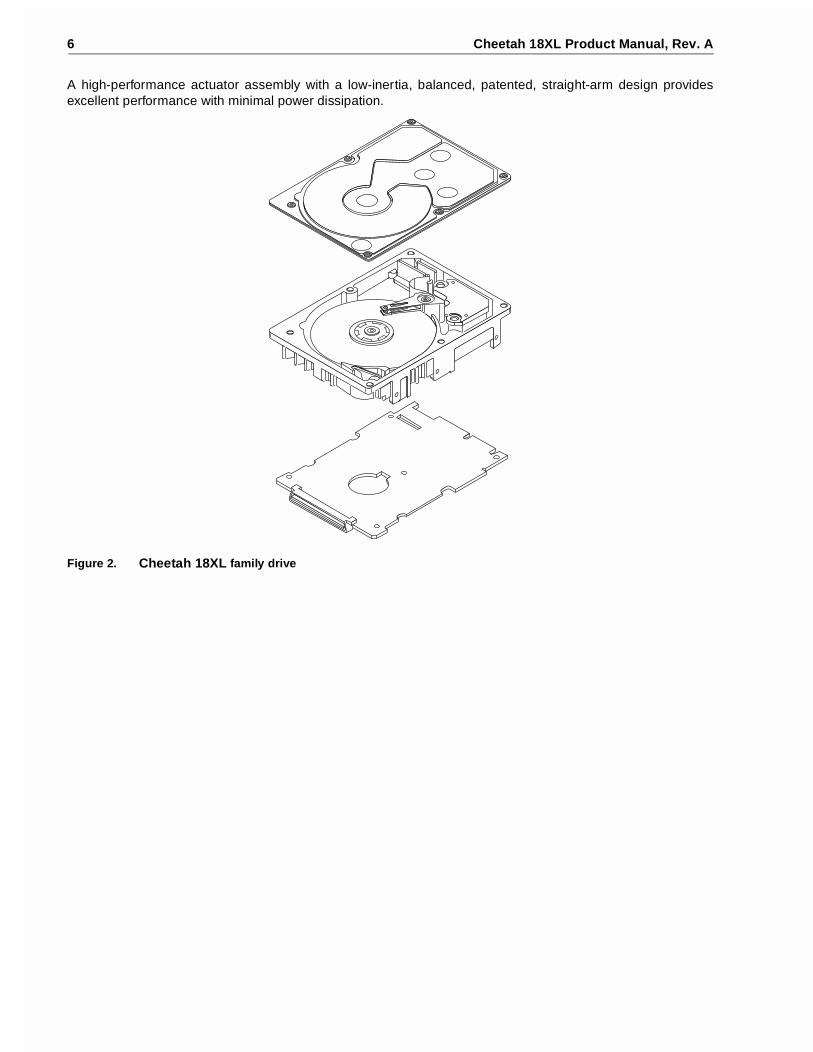
Refer to Figure 2 for an exploded view of the drive. This exploded view is for information only—never disassem-ble the HDA and do not attempt to service items in the sealed enclosure (heads, media, actuator, etc.) as thisrequires special facilities. The drive contains no replaceable parts. Opening the HDA voids your warranty.
Cheetah 18XL drives use a dedicated landing zone at the innermost radius of the media to eliminate the possi-bility of destroying or degrading data by landing in the data zone. The drive automatically goes to the landingzone when power is removed.
An automatic shipping lock prevents potential damage to the heads and discs that results from movement dur-ing shipping and handling. The shipping lock automatically disengages when power is applied to the drive andthe head load process begins.
Cheetah 18XL drives decode track 0 location data from the servo data embedded on each surface to eliminatemechanical transducer adjustments and related reliability concerns.
Model number
Number of active heads I/O circuit type [1]
Number of I/Oconnector pins
Number of I/Odata bus bits
Data buffersize (MB)
ST318404LW 6 Single-ended (SE) and lowvoltage differential (LVD)
68 16 4
ST318404LC 6 Single-ended (SE) and low voltage differential (LVD)
80 16 4
ST39204LW 3 Single-ended (SE) and low voltage differential (LVD)
68 16 4
ST39204LC 3 Single-ended (SE) and low voltage differential (LVD)
80 16 4
6 Cheetah 18XL Product Manual, Rev. A
A high-performance actuator assembly with a low-inertia, balanced, patented, straight-arm design providesexcellent performance with minimal power dissipation.
Figure 2. Cheetah 18XL family drive

Cheetah 18XL Product Manual, Rev. A 7
3.1 Standard features
The Cheetah 18XL family has the following standard features:
• Integrated Ultra160 SCSI controller• Multimode SCSI drivers and receivers—single-ended (SE) and low voltage differential (LVD)• 16 bit I/O data bus• Asynchronous and synchronous data transfer protocol• Firmware downloadable via SCSI interface• Selectable even byte sector sizes from 512 to 4,096 bytes/sector• Programmable sector reallocation scheme• Flawed sector reallocation at format time• Programmable auto write and read reallocation• Reallocation of defects on command (post format)• Enhanced ECC maximum burst correction length of 240 bits with a guaranteed burst correction length of 233
bits.• Sealed head and disc assembly• No preventative maintenance or adjustment required• Dedicated head landing zone• Embedded servo design• Self diagnostics performed when power is applied to the drive• 1:1 Interleave• Zoned bit recording (ZBR)• Vertical, horizontal, or top down mounting• Dynamic spindle brake• 4,096 kbyte data buffer• Hot plug compatibility (Section 9.6.4.2 lists proper host connector needed) for “LC” model drives• Drive Self Test (DST)
3.2 Media characteristics
The media used on the drive has a diameter of approximately 3.3 inches (84 mm). The aluminum substrate iscoated with a thin film magnetic material, overcoated with a proprietary protective layer for improved durabilityand environmental protection.
3.3 Performance
• Supports industry standard Ultra160 SCSI interface• Programmable multi-segmentable cache buffer (see Section 3.1)• 10,033 RPM spindle. Average latency = 2.99 ms• Command queuing of up to 64 commands• Background processing of queue• Supports start and stop commands (spindle stops spinning)
3.4 Reliability
• 1,200,000 hour MTBF• LSI circuitry• Balanced low mass rotary voice coil actuator• Incorporates industry-standard Self-Monitoring, Analysis and Reporting Technology (S.M.A.R.T.)• 5-year warranty

8 Cheetah 18XL Product Manual, Rev. A
3.5 Unformatted and formatted capacities
Formatted capacity depends on the number of spare reallocation sectors reserved and the number of bytes persector. The following table shows the standard OEM model capacities:
Notes.
[1] Sector size selectable at format time. Users having the necessary equipment may modify the data blocksize before issuing a format command and obtain different formatted capacities than those listed. SeeMode Select command and Format command in the SCSI Interface Product Manual, part number75789509.
[2] User available capacity depends on spare reallocation scheme selected, the number of data tracks persparing zone, and the number of alternate sectors (LBAs) per sparing zone.
3.6 Programmable drive capacity
Using the Mode Select command, the drive can change its capacity to something less than maximum. See theMode Select Parameter List table in the SCSI Interface Product Manual, part number 75789509. Refer to theParameter list block descriptor number of blocks field. A value of zero in the number of blocks field indicatesthat the drive shall not change the capacity it is currently formatted to have. A number in the number of blocksfield that is less than the maximum number of LBAs changes the total drive capacity to the value in the blockdescriptor number of blocks field. A value greater than the maximum number of LBAs is rounded down to themaximum capacity.
3.7 Factory installed accessories
OEM Standard drives are shipped with the Cheetah 18XL Installation Guide, part number 75789507, and theSafety and Regulatory Agency Specifications, part number 75789512, unless otherwise specified. The factoryalso ships with the drive a small bag of jumper plugs used for the J2, J5, and J6 option select jumper headers.
3.8 Options (factory installed)
All customer requested options are incorporated during production or packaged at the manufacturing facilitybefore shipping. Some of the options available are (not an exhaustive list of possible options):
• Other capacities can be ordered depending on sparing scheme and sector size requested.• Single unit shipping pack. The drive is normally shipped in bulk packaging to provide maximum protection
against transit damage. Units shipped individually require additional protection as provided by the single unitshipping pack. Users planning single unit distribution should specify this option.
• The Cheetah 18XL Installation Guide, part number 75789507, is usually included with each standard OEMdrive shipped, but extra copies may be ordered.
• The Safety and Regulatory Agency Specifications, part number 75789512, is usually included with eachstandard OEM drive shipped, but extra copies may be ordered.
Formatted data block size512 bytes/sector [1]
ST318404 223906Fh (18.352 GB) [2]ST39204 111C837h (9.176 GB) [2]
Cheetah 18XL Product Manual, Rev. A 9
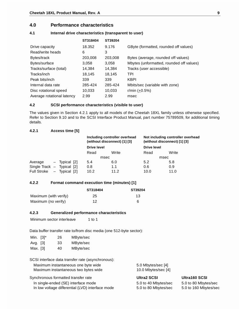
4.0 Performance characteristics
4.1 Internal drive characteristics (transparent to user)
4.2 SCSI performance characteristics (visible to user)
The values given in Section 4.2.1 apply to all models of the Cheetah 18XL family unless otherwise specified.Refer to Section 9.10 and to the SCSI Interface Product Manual, part number 75789509, for additional timingdetails.
4.2.1 Access time [5]
4.2.2 Format command execution time (minutes) [1]
4.2.3 Generalized performance characteristics
Data buffer transfer rate to/from disc media (one 512-byte sector):
SCSI interface data transfer rate (asynchronous):Maximum instantaneous one byte wide 5.0 Mbytes/sec [4]Maximum instantaneous two bytes wide 10.0 Mbytes/sec [4]
Synchronous formatted transfer rate Ultra2 SCSI Ultra160 SCSIIn single-ended (SE) interface mode 5.0 to 40 Mbytes/sec 5.0 to 80 Mbytes/secIn low voltage differential (LVD) interface mode 5.0 to 80 Mbytes/sec 5.0 to 160 Mbytes/sec
ST318404 ST39204
Drive capacity 18.352 9.176 GByte (formatted, rounded off values)Read/write heads 6 3Bytes/track 203,008 203,008 Bytes (average, rounded off values)Bytes/surface 3,058 3,058 Mbytes (unformatted, rounded off values)Tracks/surface (total) 14,384 14,384 Tracks (user accessible)Tracks/inch 18,145 18,145 TPIPeak bits/inch 339 339 KBPIInternal data rate 285-424 285-424 Mbits/sec (variable with zone)Disc rotational speed 10,033 10,033 r/min (+0.5%)Average rotational latency 2.99 2.99 msec
Including controller overhead(without disconnect) [1] [3]
Not including controller overhead(without disconnect) [1] [3]
Drive level Drive level
Read Write Read Writemsec msec
Average – Typical [2] 5.4 6.0 5.2 5.8Single Track – Typical [2] 0.8 1.1 0.6 0.9Full Stroke – Typical [2] 10.2 11.2 10.0 11.0
ST318404 ST39204
Maximum (with verify) 25 13Maximum (no verify) 12 6
Minimum sector interleave 1 to 1
Min. [3]* 26 MByte/secAvg. [3] 33 MByte/secMax. [3] 40 MByte/sec
10 Cheetah 18XL Product Manual, Rev. A
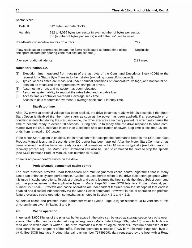
Sector Sizes:
Default 512 byte user data blocks
Variable 512 to 4,096 bytes per sector in even number of bytes per sector.If n (number of bytes per sector) is odd, then n-1 will be used.
Notes for Section 4.2.
[1] Execution time measured from receipt of the last byte of the Command Descriptor Block (CDB) to therequest for a Status Byte Transfer to the Initiator (excluding connect/disconnect).
[2] Typical access times are measured under nominal conditions of temperature, voltage, and horizontal ori-entation as measured on a representative sample of drives.
[3] Assumes no errors and no sector has been relocated.[4] Assumes system ability to support the rates listed and no cable loss.[5] Access time = controller overhead + average seek time.
Access to data = controller overhead + average seek time + latency time.
4.3 Start/stop time
After DC power at nominal voltage has been applied, the drive becomes ready within 20 seconds if the MotorStart Option is disabled (i.e. the motor starts as soon as the power has been applied). If a recoverable errorcondition is detected during the start sequence, the drive executes a recovery procedure which may cause thetime to become ready to exceed 20 seconds. During spin up to ready time the drive responds to some com-mands over the SCSI interface in less than 3 seconds after application of power. Stop time is less than 15 sec-onds from removal of DC power.
If the Motor Start Option is enabled, the internal controller accepts the commands listed in the SCSI InterfaceProduct Manual less than 3 seconds after DC power has been applied. After the Motor Start Command hasbeen received the drive becomes ready for normal operations within 16 seconds typically (excluding an errorrecovery procedure). The Motor Start Command can also be used to command the drive to stop the spindle(see SCSI Interface Product Manual, part number 75789509).
There is no power control switch on the drive.
4.4 Prefetch/multi-segmented cache control
The drive provides prefetch (read look-ahead) and multi-segmented cache control algorithms that in manycases can enhance system performance. “Cache” as used herein refers to the drive buffer storage space whenit is used in cache operations. To select prefetch and cache features the host sends the Mode Select commandwith the proper values in the applicable bytes in Mode Page 08h (see SCSI Interface Product Manual, partnumber 75789509). Prefetch and cache operation are independent features from the standpoint that each isenabled and disabled independently via the Mode Select command. However, in actual operation the prefetchfeature overlaps cache operation somewhat as is noted in Section 4.5.1 and 4.5.2.
All default cache and prefetch Mode parameter values (Mode Page 08h) for standard OEM versions of thisdrive family are given in Tables 8 and 9.
4.5 Cache operation
In general, 3,600 Kbytes of the physical buffer space in the drive can be used as storage space for cache oper-ations. The buffer can be divided into logical segments (Mode Select Page 08h, byte 13) from which data isread and to which data is written. The drive maintains a table of logical block disk medium addresses of thedata stored in each segment of the buffer. If cache operation is enabled (RCD bit = 0 in Mode Page 08h, byte 2,bit 0. See SCSI Interface Product Manual, part number 75789509), data requested by the host with a Read
Read/write consecutive sectors on a track Yes
Flaw reallocation performance impact (for flaws reallocated at format time using the spare sectors per sparing zone reallocation scheme.)
Negligible
Average rotational latency 2.99 msec

Cheetah 18XL Product Manual, Rev. A 11
command is retrieved from the buffer (if it is there), before any disc access is initiated. If cache operation is notenabled, the buffer (still segmented with required number of segments) is still used, but only as circular buffersegments during disc medium read operations (disregarding Prefetch operation for the moment). That is, thedrive does not check in the buffer segments for the requested read data, but goes directly to the medium toretrieve it. The retrieved data merely passes through some buffer segment on the way to the host. On a cachemiss, all data transfers to the host are in accordance with buffer-full ratio rules. On a cache hit the drive ignoresthe buffer-full ratio rules. See explanations associated with Mode page 02h (disconnect/reconnect control) inthe SCSI Interface Product Manual.
The following is a simplified description of a read operation with cache operation enabled:
Case A - A Read command is received and the first logical block (LB) is already in cache:
1. Drive transfers to the initiator the first LB requested plus all subsequent contiguous LBs that are already inthe cache. This data may be in multiple segments.
2. When the requested LB is reached that is not in any cache segment, the drive fetches it and any remainingrequested LBs from the disc and puts them in a segment of the cache. The drive transfers the remainingrequested LBs from the cache to the host in accordance with the disconnect/reconnect specification men-tioned above.
3. If the prefetch feature is enabled, refer to Section 4.5.2 for operation from this point.
Case B - A Read command requests data, the first LB of which is not in any segment of the cache:
1. The drive fetches the requested LBs from the disc and transfers them into a segment, and from there to thehost in accordance with the disconnect/reconnect specification referred to in case A.
2. If the prefetch feature is enabled, refer to Section 4.5.2 for operation from this point.
Each buffer segment is actually a self-contained circular storage area (wrap-around occurs), the length ofwhich is an integer number of disc medium sectors. The wrap-around capability of the individual segmentsgreatly enhances the buffer’s overall performance as a cache storage, allowing a wide range of user selectableconfigurations, which includes their use in the prefetch operation (if enabled), even when cache operation isdisabled (see Section 4.5.2). The number of segments may be selected using the Mode Select command, butthe size can not be directly selected. Size is selected only as a by-product of selecting the segment numberspecification. The size in Kbytes of each segment is not reported by the Mode Sense command page 08h,bytes 14 and 15. The value 0x0000 is always reported. If a size specification is sent by the host in a ModeSelect command (bytes 14 and 15) no new segment size is set up by the drive, and if the STRICT bit in Modepage 00h (byte 2, bit 1) is set to one, the drive responds as it does for any attempt to change unchangeableparameters (see SCSI Interface Product Manual, part number 75789509). The drive supports operation of anyinteger number of segments from 1 to 32. The default number of segments is defined in Tables 8 and 9.
4.5.1 Caching write data
Write caching is a write operation by the drive that makes use of a drive buffer storage area where the data tobe written to the medium is stored in one or more segments while the drive performs the write command.
If read caching is enabled (RCD=0), then data written to the medium is retained in the cache to be made avail-able for future read cache hits. The same buffer space and segmentation is used as set up for read functions.The buffer segmentation scheme is set up or changed independently, having nothing to do with the state ofRCD. When a write command is issued, if RCD=0, the cache is first checked to see if any logical blocks thatare to be written are already stored in the cache from a previous read or write command. If there are, therespective cache segments are cleared. The new data is cached for subsequent Read commands.
If the number of write data logical blocks exceeds the size of the segment being written into, when the end ofthe segment is reached, the data is written into the beginning of the same cache segment, overwriting the datathat was written there at the beginning of the operation. However, the drive does not overwrite data that has notyet been written to the medium.
If write caching is enabled (WCE=1), then the drive may return GOOD status on a write command after thedata has been transferred into the cache, but before the data has been written to the medium. If an error occurswhile writing the data to the medium, and GOOD status has already been returned, a deferred error will begenerated.

12 Cheetah 18XL Product Manual, Rev. A
The Synchronize Cache command may be used to force the drive to write all cached write data to the medium.Upon completion of a Synchronize Cache command, all data received from previous write commands will havebeen written to the medium.
Tables 8 and 9 show Mode default settings for the drives.
4.5.2 Prefetch operation
If the Prefetch feature is enabled, data in contiguous logical blocks on the disc immediately beyond that whichwas requested by a Read command can be retrieved and stored in the buffer for immediate transfer from thebuffer to the host on subsequent Read commands that request those logical blocks (this is true even if cacheoperation is disabled). Though the prefetch operation uses the buffer as a cache, finding the requested data inthe buffer is a prefetch hit, not a cache operation hit. Prefetch is enabled using Mode Select page 08h, byte 12,bit 5 (Disable Read Ahead - DRA bit). DRA bit = 0 enables prefetch. Since data that is prefetched replaces dataalready in some buffer segment(s), the host can limit the amount of prefetch data to optimize system perfor-mance. The max prefetch field (bytes 8 and 9) limits the amount of prefetch. The drive does not use thePrefetch Ceiling field (bytes 10 and 11).
During a prefetch operation, the drive crosses a cylinder boundary to fetch more data only if the Discontinuity(DISC) bit is set to one in bit 4 of byte 2 of Mode parameters page 08h.
Whenever prefetch (read look-ahead) is enabled (enabled by DRA = 0), it operates under the control of ARLA(Adaptive Read Look-Ahead). If the host uses software interleave, ARLA enables prefetch of contiguous blocksfrom the disc when it senses that a prefetch hit will likely occur, even if two consecutive read operations werenot for physically contiguous blocks of data (e.g., “software interleave”). ARLA disables prefetch when itdecides that a prefetch hit will not likely occur. If the host is not using software interleave, and if two sequentialread operations are not for contiguous blocks of data, ARLA disables prefetch, but as long as sequential readoperations request contiguous blocks of data, ARLA keeps prefetch enabled.

Cheetah 18XL Product Manual, Rev. A 13
5.0 Reliability specifications
The following reliability specifications assume correct host/drive operational interface, including all interfacetimings, power supply voltages, environmental requirements and drive mounting constraints (see Section 8.4).
Note.
[1] Error rate specified with automatic retries and data correction with ECC enabled and all flaws reallocated.
5.1 Error rates
The error rates stated in this specification assume the following:
• The drive is operated per this specification using DC power as defined in this manual (see Section 6.2).• The drive has been formatted with the SCSI FORMAT command.• Errors caused by media defects or host system failures are excluded from error rate computations. Refer to
Section 3.2, “Media Characteristics.”• Assume random data.
5.1.1 Environmental interference
When evaluating systems operation under conditions of Electromagnetic Interference (EMI), the performanceof the drive within the system shall be considered acceptable if the drive does not generate an unrecoverablecondition.
An unrecoverable error, or unrecoverable condition, is defined as one that:
• Is not detected and corrected by the drive itself;• Is not capable of being detected from the error or fault status provided through the drive or SCSI interface; or• Is not capable of being recovered by normal drive or system recovery procedures without operator interven-
tion.
5.1.2 Read errors
Before determination or measurement of read error rates:
• The data that is to be used for measurement of read error rates must be verified as being written correctly onthe media.
• All media defect induced errors must be excluded from error rate calculations.
5.1.3 Write errors
Write errors can occur as a result of media defects, environmental interference, or equipment malfunction.Therefore, write errors are not predictable as a function of the number of bits passed.
If an unrecoverable write error occurs because of an equipment malfunction in the drive, the error is classifiedas a failure affecting MTBF. Unrecoverable write errors are those which cannot be corrected within twoattempts at writing the record with a read verify after each attempt (excluding media defects).
5.1.4 Seek errors
A seek error is defined as a failure of the drive to position the heads to the addressed track. There shall be nomore than ten recoverable seek errors in 108 physical seek operations. After detecting an initial seek error, thedrive automatically performs an error recovery process. If the error recovery process fails, a seek positioning
Seek Errors Less than 10 in 108 seeksRead Error Rates [1]
Recovered Data Less than 10 errors in 1012 bits transferred (OEM default settings)Unrecovered Data Less than 1 sector in 1015 bits transferred (OEM default settings)Miscorrected Data Less than 1 sector in 1021 bits transferred
MTBF 1,200,000 hoursService Life 5 yearsPreventive Maintenance None required
14 Cheetah 18XL Product Manual, Rev. A
error (15h) is reported with a Medium error (3h) or Hardware error (4h) reported in the Sense Key. This is anunrecoverable seek error. Unrecoverable seek errors are classified as failures for MTBF calculations. Refer tothe SCSI Interface Product Manual, part number 75789509, for Request Sense information.
5.2 Reliability and service
You can enhance the reliability of Cheetah 18XL disc drives by ensuring that the drive receives adequate cool-ing. Section 6.0 provides temperature measurements and other information that may be used to enhance theservice life of the drive. Section 8.3.1 provides recommended air-flow information.
5.2.1 Mean time between failure
The production disc drive shall achieve an MTBF of 1,200,000 hours when operated in an environment thatensures the case temperatures specified in Section 6.4.1, Table 3 are not exceeded. Short-term excursions upto the specification limits of the operating environment will not affect MTBF performance. Continual or sus-tained operation at case temperatures above the values shown in Table 3 may degrade product reliability.
The MTBF target is specified as device power-on hours (POH) for all drives in service per failure.
Estimated power-on operating hours in the period = MTBF per measurement period
Number of drive failures in the period
Estimated power-on operation hours means power-up hours per disc drive times the total number of disc drivesin service. Each disc drive shall have accumulated at least nine months of operation. Data shall be calculatedon a rolling average base for a minimum period of six months.
MTBF is based on the following assumptions:
• 8,760 power-on hours per year.• 250 average on/off cycles per year. • Operations at nominal voltages.• Systems will provide adequate cooling to ensure the case temperatures specified in Section 6.4.1 are not
exceeded.
Drive failure means any stoppage or substandard performance caused by drive malfunction.
A S.M.A.R.T. predictive failure indicates that the drive is deteriorating to an imminent failure and is consideredan MTBF hit.
5.2.2 Field failure rate vs time
The expected field failure rate is listed below. Drive utilization will vary. An estimated range of utilization is:
• 720 power-on hours (POH) per month.• 250 on/off cycles per year.• Read/seek/write operation 20% of power-on hours.• Systems will provide adequate cooling to ensure the case temperatures specified in Section 6.4.1 are not
exceeded.
Failure rate is calculated as follows:
• No system-induced failures are counted• Based on 1,200,000 MTBF and 720 power-on hours per month• Month 1’s rate includes a 300 PPM installation failure
Month 1 2,500 PPMMonth 2 1,650 PPMMonth 3 1,200 PPMMonth 4 1,000 PPMMonth 5 890 PPMMonth 6 840 PPMMonth 7 805 PPM
Cheetah 18XL Product Manual, Rev. A 15
5.2.3 Preventive maintenance
No routine scheduled preventive maintenance shall be required.
5.2.4 Service life
The drive shall have a useful service life of five years. Depot repair or replacement of major parts is permittedduring the lifetime (see Section 5.2.5)
5.2.5 Service philosophy
Special equipment is required to repair the drive HDA. In order to achieve the above service life, repairs mustbe performed only at a properly equipped and staffed service and repair facility. Troubleshooting and repair ofPCBs in the field is not recommended, because of the extensive diagnostic equipment required for effectiveservicing. Also, there are no spare parts available for this drive. Drive warranty is voided if the HDA is opened.
5.2.6 Service tools
No special tools are required for site installation or recommended for site maintenance. Refer to Section 5.2.5.The depot repair philosophy of the drive precludes the necessity for special tools. Field repair of the drive is notpractical since there are no user purchasable parts in the drive.
5.2.7 Hot plugging Cheetah 18XL disc drives
The ANSI SPI-3 (T10/1302D) document defines the physical requirements for removal and insertion of SCSIdevices on the SCSI bus. Four cases are addressed. The cases are differentiated by the state of the SCSI buswhen the removal or insertion occurs.
Case 1 - All bus devices powered off during removal or insertion
Case 2 - RST signal asserted continuously during removal or insertion
Case 3 - Current I/O processes not allowed during insertion or removal
Case 4 - Current I/O process allowed during insertion or removal, except on the device being changed
Seagate Cheetah 18XL disc drives support all four hot plugging cases. Provision shall be made by the systemsuch that a device being inserted makes power and ground connections prior to the connection of any devicesignal contact to the bus. A device being removed shall maintain power and ground connections after the dis-connection of any device signal contact from the bus (see SFF-8046, SCA-2 specification).
It is the responsibility of the systems integrator to assure that no hazards from temperature, energy, voltage, orESD potential are presented during the hot connect/disconnect operation.
All I/O processes for the SCSI device being inserted or removed shall be quiescent. All SCSI devices on thebus shall have receivers that conform to the SPI-3 standard.
If the device being hot plugged uses single-ended (SE) drivers and the bus is currently operating in low voltagedifferential (LVD) mode, then all I/O processes for all devices on the bus must be completed, and the bus qui-esced, before attempting to hot plug. Following the insertion of the newly installed device, the SCSI hostadapter must issue a Bus Reset, followed by a synchronous transfer negotiation. Failure to perform the SCSIBus Reset could result in erroneous bus operations.
The SCSI bus termination and termination power source shall be external to the device being inserted orremoved.
End users should not mix devices with high voltage differential (HVD) drivers and receivers and devices withSE, LVD, or multimode drivers and receivers on the same SCSI bus since the common mode voltages in theHVD environment may not be controlled to safe levels for SE and LVD devices (see ANSI SPI-3).
The disc drive spindle must come to a complete stop prior to completely removing the drive from the cabinetchassis. Use of the Stop Spindle command or partial withdrawal of the drive, enough to be disconnected fromthe power source, prior to removal are methods for insuring that this requirement is met. During drive insertion,care should be taken to avoid exceeding the limits stated in Section 6.4.4, "Shock and vibration" in this manual.

16 Cheetah 18XL Product Manual, Rev. A
5.2.8 S.M.A.R.T.
S.M.A.R.T. is an acronym for Self-Monitoring Analysis and Reporting Technology. This technology is intendedto recognize conditions that indicate a drive failure and is designed to provide sufficient warning of a failure toallow data back-up before an actual failure occurs.
Note. The firmware will monitor specific attributes for degradation over time but cannot predict instantaneousdrive failures.
Each attribute has been selected to monitor a specific set of failure conditions in the operating performance ofthe drive, and the thresholds are optimized to minimize “false” and “failed” predictions.
Controlling S.M.A.R.T.
The operating mode of S.M.A.R.T. is controlled by the DEXCPT bit and the PERF bit of the “InformationalExceptions Control Mode Page” (1Ch). The DEXCPT bit is used to enable or disable the S.M.A.R.T. process.Setting the DEXCPT bit will disable all S.M.A.R.T. functions. When enabled, S.M.A.R.T. will collect on-line dataas the drive performs normal read/write operations. When the PERF bit is set, the drive is considered to be in“On-line Mode Only” and will not perform off-line functions.
The process of measuring off-line attributes and saving data can be forced by the RTZ command. ForcingS.M.A.R.T. will reset the timer so that the next scheduled interrupt will be two hours.
The drive can be interrogated by the host to determine the time remaining before the next scheduled measure-ment and data logging process will occur. This is accomplished by a log sense command to log page 0x3E.The purpose is to allow the customer to control when S.M.A.R.T. interruptions occur. As described above, forc-ing S.M.A.R.T by the Rezero Unit command will reset the timer.
Performance impact
S.M.A.R.T. attribute data will be saved to the disc for the purpose of recreating the events that caused a predic-tive failure. The drive will measure and save parameters once every two hours subject to an idle period on theSCSI bus. The process of measuring off-line attribute data and saving data to the disc is uninterruptable andthe maximum delay is summarized below:
Maximum processing delay
On-line only delay Fully enabled delayDEXCPT = 0, PERF = 1 DEXCPT = 0, PERF = 0
S.M.A.R.T. delay times ST318404: 93 ms; ST39204: 57 ms ST318404: 164 ms; ST39204: 150 ms
Reporting control
Reporting is controlled in the Informational Exceptions Control Page (1Ch). Subject to the reporting method,the firmware will issue a 01-5D00 sense code to the host. The error code is preserved through bus resets andpower cycles.
Determining rate
S.M.A.R.T. monitors the rate at which errors occur and signals a predictive failure if the rate of degraded errorrate increases to an unacceptable level. To determine rate, error events are logged and compared to the num-ber of total operations for a given attribute. The interval defines the number of operations over which to mea-sure the rate. The counter that keeps track of the current number of operations is referred to as the IntervalCounter.
S.M.A.R.T. measures error rate, hence for each attribute the occurrence of an error is recorded. A counterkeeps track of the number of errors for the current interval. This counter is referred to as the Failure Counter.
Error rate is simply the number of errors per operation. The algorithm that S.M.A.R.T. uses to record rates oferror is to set thresholds for the number of errors and the interval. If the number of errors exceeds the thresholdbefore the interval expires, then the error rate is considered to be unacceptable. If the number of errors doesnot exceed the threshold before the interval expires, then the error rate is considered to be acceptable. In eithercase, the interval and failure counters are reset and the process starts over.

Cheetah 18XL Product Manual, Rev. A 17
Predictive failures
S.M.A.R.T. signals predictive failures when the drive is performing unacceptably for a period of time. The firm-ware keeps a running count of the number of times the error rate for each attribute is unacceptable. To accom-plish this, a counter is incremented whenever the error rate is unacceptable and decremented (not to exceedzero) whenever the error rate is acceptable. Should the counter continually be incremented such that it reachesthe predictive threshold, a predictive failure is signaled. This counter is referred to as the Failure HistoryCounter. There is a separate Failure History Counter for each attribute.
5.2.9 Drive Self Test (DST)
Drive Self Test (DST) is a technology designed to recognize drive fault conditions that qualify the drive as a failed unit. DST validates the functionality of the drive at a system level.
There are two test coverage options implemented in DST:
1. Extended test2. Short text
The most thorough option is the extended test that performs various tests on the drive and scans every logical block address (LBA) of the drive. The short test is time-restricted and limited in length—it does not scan the entire media surface, but does some fundamental tests and scans portions of the media.
If DST encounters an error during either of these tests, it reports a fault condition. If the drive fails the test, remove it from service and return it to Seagate for service.
5.2.9.1 DST Failure Definition
The drive will present a “diagnostic failed” condition through the self-tests results value of the diagnostic log page if a functional failure is encountered during DST. The channel and servo parameters are not modified to test the drive more stringently, and the number of retries are not reduced. All retries and recovery processes are enabled during the test. If data is recoverable, no failure condition will be reported regardless of the number of retries required to recover the data.
The following conditions are considered DST failure conditions:
• Seek error after retries are exhausted
• Track-follow error after retries are exhausted
• Read error after retries are exhausted
• Write error after retries are exhausted.
Recovered errors will not be reported as diagnostic failures.
5.2.9.2 Implementation
This section provides all of the information necessary to implement the DST function on this drive.
5.2.9.2.1 State of the drive prior to testing
The drive must be in a ready state before issuing the Send Diagnostic command. There are multiple reasons why a drive may not be ready, some of which are valid conditions, and not errors. For example, a drive may be in process of doing a format, or another DST. It is the responsibility of the host application to determine the “not ready” cause.
While not technically part of DST, a Not Ready condition also qualifies the drive to be returned to Seagate as a failed drive.
A Drive Not Ready condition is reported by the drive under the following conditions:
• Motor will not spin
• Motor will not lock to speed
• Servo will not lock on track
• Drive cannot read configuration tables from the disc
In these conditions, the drive responds to a Test Unit Ready command with an 02/04/00 or 02/04/03 code.

18 Cheetah 18XL Product Manual, Rev. A
5.2.9.2.2 Invoking DST
To invoke DST, submit the Send Diagnostic command with the appropriate Function Code (001b for the short test or 010b for the extended test) in bytes 1, bits 5, 6, and 7. Refer to the Seagate SCSI Interface Manual, Vol-ume 3, part number 75789509 for additional information about invoking DST.
5.2.9.2.3 Short and extended tests
DST has two testing options:
1. short2. extended
These testing options are described in the following two subsections.
Each test consists of three segments: an electrical test segment, a servo test segment, and a read/verify scan segment.
Short test (Function Code: 001b)
The purpose of the short test is to provide a time-limited test that tests as much of the drive as possible within 120 seconds. The short test does not scan the entire media surface, but does some fundamental tests and scans portions of the media. A complete read/verify scan is not performed and only factual failures will report a fault condition. This option provides a quick confidence test of the drive.
Extended test (Function Code: 010b)
The objective of the extended test option is to empirically test critical drive components. For example, the seek tests and on-track operations test the positioning mechanism. The read operation tests the read head element and the media surface. The write element is tested through read/write/read operations. The integrity of the media is checked through a read/verify scan of the media. Motor functionality is tested by default as a part of these tests.
The anticipated length of the Extended test is reported through the Control Mode page.
5.2.9.2.4 Log page entries
When the drive begins DST, it creates a new entry in the Self-test Results Log page. The new entry is created by inserting a new self-test parameter block at the beginning of the self-test results log parameter section of the log page. Existing data will be moved to make room for the new parameter block. The drive reports 20 parame-ter blocks in the log page. If there are more than 20 parameter blocks, the least recent parameter block will be deleted. The new parameter block will be initialized as follows:
1. The Function Code field is set to the same value as sent in the DST command
2. The Self-Test Results Value field is set to Fh
3. The drive will store the log page to non-volatile memory
After a self-test is complete or has been aborted, the drive updates the Self-Test Results Value field in its Self-Test Results Log page in non-volatile memory. The host may use Log Sense to read the results from up to the last 20 self-tests performed by the drive. The self-test results value is a 4-bit field that reports the results of the test. If the field is zero, the drive passed with no errors detected by the DST. If the field is not zero, the test failed for the reason reported in the field.
The drive will report the failure condition and LBA (if applicable) in the Self-test Results Log parameter. The Sense key, ASC, ASCQ, and FRU are used to report the failure condition.
5.2.9.2.5 Abort
There are several ways to abort a diagnostic. You can use a SCSI Bus Reset or a Bus Device Reset message to abort the diagnostic.
You can abort a DST executing in background mode by using the abort code in the DST Function Code field. This will cause a 01 (self-test aborted by the application client) code to appear in the self-test results values log. All other abort mechanisms will be reported as a 02 (self-test routine was interrupted by a reset condition).

Cheetah 18XL Product Manual, Rev. A 19
5.2.10 Product warranty
Beginning on the date of shipment to customer and continuing for a period of five years, Seagate warrants thateach product (including components and subassemblies) or spare part that fails to function properly under nor-mal use due to defect in materials on workmanship or due to nonconformance to the applicable specificationswill be repaired or replaced, at Seagate’s option and at no charge to customer, if returned by customer at cus-tomer’s expense to Seagate’s designated facility in accordance with Seagate’s warranty procedure. Seagatewill pay for transporting the repair or replacement item to customer. For more detailed warranty informationrefer to the Standard terms and conditions of Purchase for Seagate products.
Shipping
When transporting or shipping a drive, a Seagate approved container must be used. Keep your original box.They are easily identified by the Seagate-approved package label. Shipping a drive in a non-approved con-tainer voids the drive warranty.
Seagate repair centers may refuse receipt of components improperly packaged or obviously damaged in tran-sit. Contact your Authorized Seagate Distributor to purchase additional boxes. Seagate recommends shippingby an air-ride carrier experienced in handling computer equipment.
Product repair and return information
Seagate customer service centers are the only facilities authorized to service Seagate drives. Seagate doesnot sanction any third-party repair facilities. Any unauthorized repair or tampering with the factory-seal voidsthe warranty.


Cheetah 18XL Product Manual, Rev. A 21
6.0 Physical/electrical specifications
This section provides information relating to the physical and electrical characteristics of the Cheetah 18XLdrive.
6.1 AC power requirements
None.
6.2 DC power requirements
The voltage and current requirements for a single drive are shown in the following table. Values indicated applyat the drive power connector. The table shows current values in Amperes.
Table 2: DC power requirements
[1] Measured with average reading DC ammeter or equivalent sampling scope. Instantaneous current peakswill exceed these values. Power supply at nominal voltage. N = 2, 22 Degrees C ambient.
[2] For +12 V, a –10% tolerance is permissible during initial start of spindle, and must return to ±5% before10,017 rpm is reached. The ±5% must be maintained after the drive signifies that its power-up sequencehas been completed and that the drive is able to accept selection by the host initiator.
[3] See +12 V current profile in Figure 3.[4] This condition occurs when the Motor Start Option is enabled and the drive has not yet received a Start
Motor command.[5] See Section 6.2.1 “Conducted Noise Immunity.” Specified voltage tolerance is inclusive of ripple, noise,
and transient response.[6] Operating condition is defined as random 8 block reads at 204 I/Os per second. Current and power speci-
fied at nominal voltages. Decreasing +5 volts by +5% increases +5 volt current by 3.58%.[7] During idle, the drive heads are relocated every 60 seconds to a random location within the band from
track zero to one-fourth of maximum track.
General Notes from Table 2:
1. Minimum current loading for each supply voltage is not less than 1.2% of the maximum operating currentshown.
2. The +5 and +12 volt supplies shall employ separate ground returns.
3. Where power is provided to multiple drives from a common supply, careful consideration for individual drivepower requirements should be noted. Where multiple units are powered on simultaneously, the peak start-ing current must be available to each device.
4. Parameters, other than spindle start, are measured after a 10-minute warm up.
5. No terminator power.
NotesST318404 ST39204
SE mode LVD mode SE mode LVD mode
Voltage +5 V +12 V +5 V +12 V +5 V +12 V +5 V +12 V
Regulation [5] ±5% ±5%[2] ±5% ±5%[2] ±5% ±5%[2] ±5% ±5%[2]
Average idle current DCX [1][7] 0.70 0.40 0.70 0.40 0.55 0.35 0.55 0.35
Maximum starting current(peak DC) DC(peak AC) AC
[3][3]
0.7 1.72.4
0.7 1.72.4
0.7 1.72.3
0.7 1.72.3
Delayed motor start (max) DC [1][4] 0.6 0.03 0.6 0.03 0.6 0.03 0.6 0.03
Peak operating currentDCXMaximum DCMaximum (peak) DC
[1][6][1]
0.961.01.5
0.930.972.3
0.961.01.5
0.930.972.3
0.800.801.2
0.750.802.0
0.800.801.2
0.750.802.0

22 Cheetah 18XL Product Manual, Rev. A
6.2.1 Conducted noise immunity
Noise is specified as a periodic and random distribution of frequencies covering a band from DC to 10 MHz.Maximum allowed noise values given below are peak to peak measurements and apply at the drive power con-nector.
6.2.2 Power sequencing
The drive does not require power sequencing. The drive protects against inadvertent writing during power-upand down. Daisy-chain operation requires that power be maintained on the SCSI bus terminator to ensureproper termination of the peripheral I/O cables. To automatically delay motor start based on the target ID (SCSIID) enable the Delay Motor Start option and disable the Enable Motor Start option on the J2 connector. SeeSection 8.1 for pin selection information. To delay the motor until the drive receives a Start Unit command,enable the Enable Remote Motor Start option on the J2 connector.
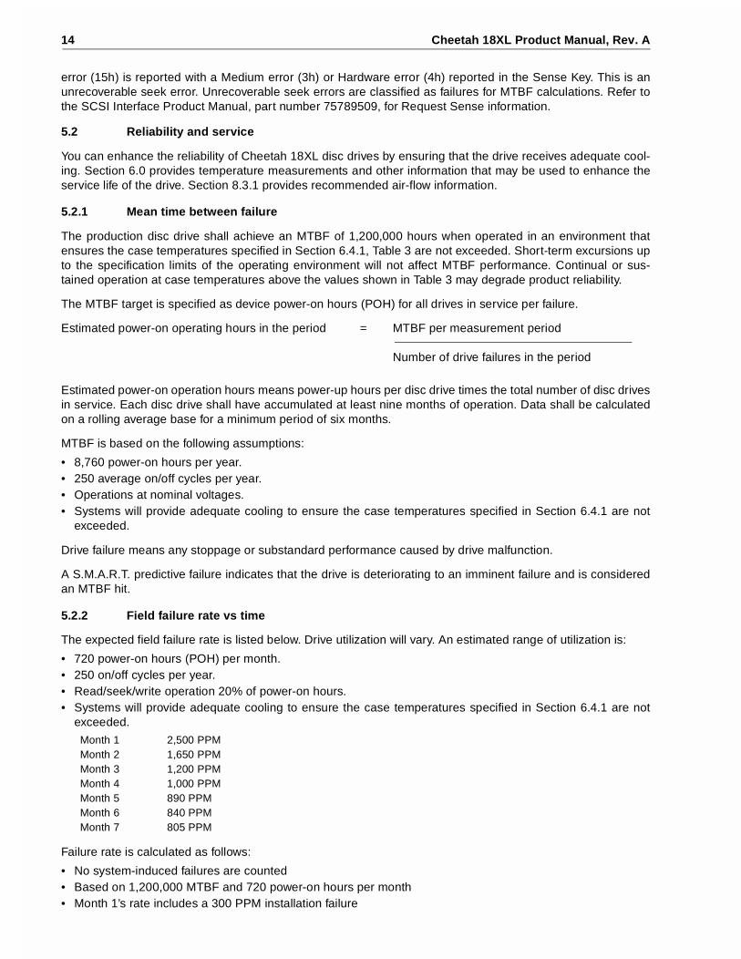
6.2.3 12 V - Current profile
Figure 3 identifies the drive +12 V current profile. The current during the various times is as shown:
Note. All times and currents are typical. See Table 2 for maximum current requirements.
+5 V = 150 mV pp from 0 to 100 kHz and 100 mV pp from 100 kHz to 10 MHz.+12 V = 150 mV pp from 0 to 100 kHz and 100 mV pp from 100 kHz to 10 MHz.
T0 - Power is applied to the drive.T1 - Controller self tests are performed.T2 - Spindle begins to accelerate under current limiting after performing drive internal
diagnostics. See Note 1 of Table 2.T3 - The spindle is up to speed and the head-arm restraint is unlocked.T4 - The adaptive servo calibration sequence is performed.T5 - Calibration is complete and drive is ready for reading and writing.
Cheetah 18XL Product Manual, Rev. A 23
Figure 3. Typical ST318404 drive +12 V current profile
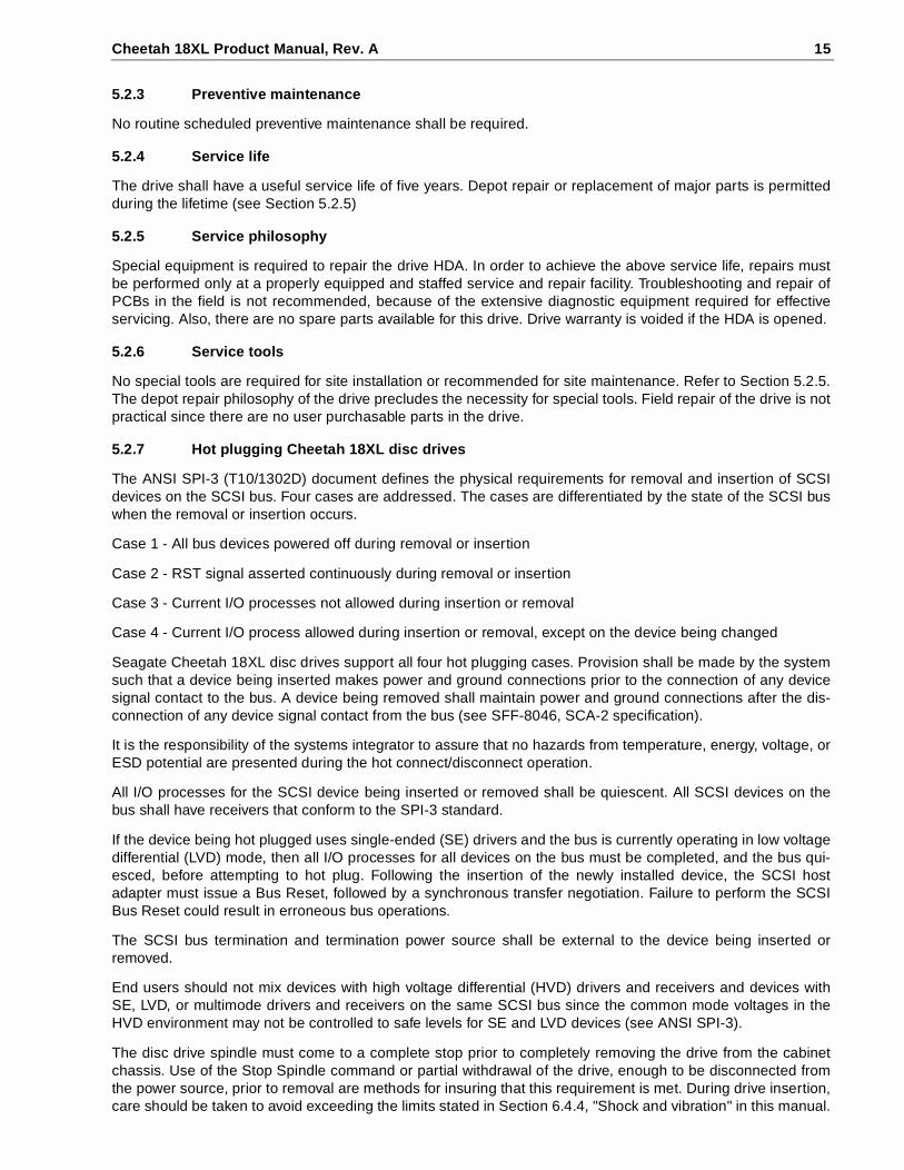
Figure 4. Typical ST39204 drive +12 V current profile
0.0 2 4 6 8 10 12 14 16 18 20
0.0
0.5
1.0
1.5
2.0
2.5
3.0
A
Seconds
T2 T4T3
T
AC Envelope
Nominal (average)DC curve
+12 Volt Current during spindle start – Typical Amperes
T5T1
0.0 2 4 6 8 10 12 14 16 18 20
0.0
0.5
1.0
1.5
2.0
2.5
3.0
A
Seconds
AC Envelope
Nominal (average)DC curve
+12 Volt Current during spindle start – Typical Amperes

24 Cheetah 18XL Product Manual, Rev. A
Figure 5. Typical ST318404 drive +5 V current profile
Figure 6. TypicalST39204 drive +5 V current profile
0.0 2 4 6 8 10 12 14 16 18 20
0.0
0.2
0.4
0.6
0.8
1.0
1.2
A
Seconds
Nominal (average) DC curve
+5 Volt Current during spindle start – Typical Amperes
0.0 2 4 6 8 10 12 14 16 18 20
0.0
0.2
0.4
0.6
0.8
1.0
1.2
A
Seconds
Nominal (average) DC curve
+5 Volt Current during spindle start – Typical Amperes

Cheetah 18XL Product Manual, Rev. A 25
6.3 Power dissipation
ST318404
For drives using single-ended interface circuits, typical power dissipation under idle conditions is 8.5 watts(29.0 BTUs per hour).
For drives using low voltage differential interface circuits, typical power dissipation under idle conditions is 8.5watts (29.0 BTUs per hour).
To obtain operating power for typical random read operations, refer to the following two I/O rate curves (seeFigures 7 and 8). Locate the typical I/O rate for a drive in your system on the horizontal axis and read the cor-responding +5 volt current, +12 volt current, and total watts on the vertical axis. To calculate BTUs per hour,multiply watts by 3.4123.
Figure 7. ST318404 DC current and power vs. input/output operations per second (SE)
Figure 8. ST318404 DC current and power vs. input/output operations per second (LVD)
0.00 50 100
I/Os per Second
Am
per
es
150
0.2
0.4
0.6
0.8
1.0
1.25V A12V A
0.00 50 100
I/Os per Second
Am
per
es
150
0.2
0.4
0.6
0.8
1.0
1.25V A12V A

26 Cheetah 18XL Product Manual, Rev. A
ST39204
For drives using single-ended interface circuits, typical power dissipation under idle conditions is 7.0 watts(23.8 BTUs per hour).
For drives using low voltage differential interface circuits, typical power dissipation under idle conditions is 7.0watts (23.8 BTUs per hour).
To obtain operating power for typical random read operations, refer to the following two I/O rate curves (seeFigures 9 and 10). Locate the typical I/O rate for a drive in your system on the horizontal axis and read the cor-responding +5 volt current, +12 volt current, and total watts on the vertical axis. To calculate BTUs per hour,multiply watts by 3.4123.
Figure 9. ST39204 DC current and power vs. input/output operations per second (SE)
Figure 10. ST39204 DC current and power vs. input/output operations per second (LVD)
0.00 50 100
I/Os per Second
Am
per
es
150
0.2
0.4
0.6
0.8
1.0
1.25V A12V A
0.00 50 100
I/Os per Second
Am
per
es
150
0.2
0.4
0.6
0.8
1.0
1.25V A12V A

Cheetah 18XL Product Manual, Rev. A 27
6.4 Environmental limits
Temperature and humidity values experienced by the drive must be such that condensation does not occur onany drive part. Altitude and atmospheric pressure specifications are referenced to a standard day at 58.7°F(14.8°C). Maximum wet bulb temperature is 82°F (28°C).
6.4.1 Temperature
a. Operating
With cooling designed to maintain the case temperatures of Table 3, Column 2, the drive meets all specifi-cations over a 41°F to 131°F (5°C to 55°C) drive ambient temperature range with a maximum temperaturegradient of 36°F (20°C) per hour. The enclosure for the drive should be designed such that the tempera-tures at the locations specified in Table 3, column 1 are not exceeded. Air flow may be needed to achievethese temperature values (see Section 8.3 and 8.3.1). Operation at case temperatures above these valuesmay adversely affect the drives ability to meet specifications.
The MTBF specification for the drive is based on operating in an environment that ensures that the casetemperatures specified in Table 3, column 2 are not exceeded. Occasional excursions to drive ambient tem-peratures of 131°F (55°C) or 41°F (5°C) may occur without impact to specified MTBF. Air flow may beneeded to achieve these temperatures (see Section 8.3.1). Continual or sustained operation at case tem-peratures above these values may degrade MTBF.
To confirm that the required cooling for the electronics and HDA is provided, place the drive in its finalmechanical configuration, perform random write/read operations. After the temperatures stabilize, measurethe case temperature of the components listed in Table 3 (see note [3]).
The maximum allowable HDA case temperature is 65°C. Operation of the drive at the maximum case tem-perature is intended for short time periods only. Continuous operation at the elevated temperatures willreduce product reliability.
Table 3: PCBA and HDA temperatures
Notes.
[1] Section 8.3.1 describes the air-flow patterns to be used to meet case temperatures in column 2. Airflow was opposite that shown in Section 8.3.1. Air velocity should be adequate to ensure that the casetemperatures in column 2 are not exceeded during drive operation.
[2] The temperatures in columns 1 and 2 are calculated and may not reflect actual operating values. Suffi-cient cooling is required to ensure that these values are not exceeded.
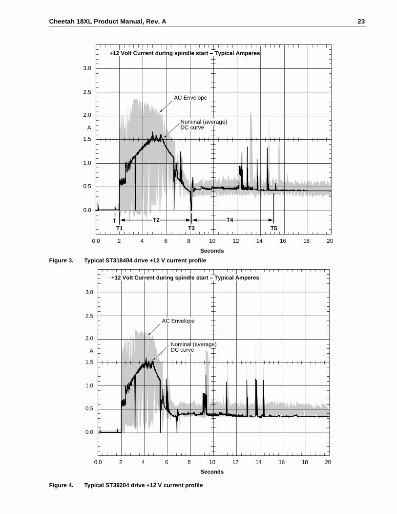
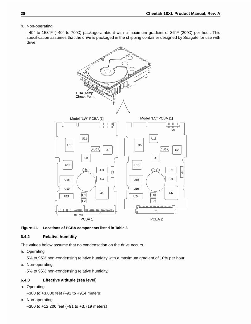
[3] Measure HDA temp at point labeled “HDA” on Figure 11.[4] PCB mounted integrated circuit case.
Items inFigure 11
Column 1Maximum case [4]temperature (°C)operating (55° ambient)[3]
Column 2Maximum allowablecase [4] temperatures (°C)to meet MTBF spec.[3]
HDA [3] 65 50U2 123 103U5 123 103U11 105 85U8 105 85
28 Cheetah 18XL Product Manual, Rev. A
b. Non-operating
–40° to 158°F (–40° to 70°C) package ambient with a maximum gradient of 36°F (20°C) per hour. Thisspecification assumes that the drive is packaged in the shipping container designed by Seagate for use withdrive.
Figure 11. Locations of PCBA components listed in Table 3
6.4.2 Relative humidity
The values below assume that no condensation on the drive occurs.
a. Operating
5% to 95% non-condensing relative humidity with a maximum gradient of 10% per hour.
b. Non-operating
5% to 95% non-condensing relative humidity.
6.4.3 Effective altitude (sea level)
a. Operating
–300 to +3,000 feet (–91 to +914 meters)
b. Non-operating
–300 to +12,200 feet (–91 to +3,719 meters)
Model “LW” PCBA [1] Model “LC” PCBA [1]
PCBA 1 PCBA 2
J1J1
J6
U15
U6
J2
U2
U16
U8
U11
U5
J3
U4
U3
U18
U19
U24 L8
HDA Temp.Check Point
.5"
L7L7
U15
U6
J2
U2
U16
U8
U11
U5
J3
U4
U3
U18
U19
U24 L8
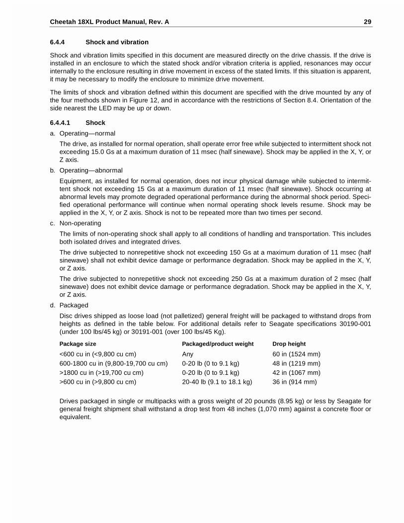
Cheetah 18XL Product Manual, Rev. A 29
6.4.4 Shock and vibration
Shock and vibration limits specified in this document are measured directly on the drive chassis. If the drive isinstalled in an enclosure to which the stated shock and/or vibration criteria is applied, resonances may occurinternally to the enclosure resulting in drive movement in excess of the stated limits. If this situation is apparent,it may be necessary to modify the enclosure to minimize drive movement.
The limits of shock and vibration defined within this document are specified with the drive mounted by any ofthe four methods shown in Figure 12, and in accordance with the restrictions of Section 8.4. Orientation of theside nearest the LED may be up or down.
6.4.4.1 Shock
a. Operating—normal
The drive, as installed for normal operation, shall operate error free while subjected to intermittent shock notexceeding 15.0 Gs at a maximum duration of 11 msec (half sinewave). Shock may be applied in the X, Y, orZ axis.
b. Operating—abnormal
Equipment, as installed for normal operation, does not incur physical damage while subjected to intermit-tent shock not exceeding 15 Gs at a maximum duration of 11 msec (half sinewave). Shock occurring atabnormal levels may promote degraded operational performance during the abnormal shock period. Speci-fied operational performance will continue when normal operating shock levels resume. Shock may beapplied in the X, Y, or Z axis. Shock is not to be repeated more than two times per second.
c. Non-operating
The limits of non-operating shock shall apply to all conditions of handling and transportation. This includesboth isolated drives and integrated drives.
The drive subjected to nonrepetitive shock not exceeding 150 Gs at a maximum duration of 11 msec (halfsinewave) shall not exhibit device damage or performance degradation. Shock may be applied in the X, Y,or Z axis.
The drive subjected to nonrepetitive shock not exceeding 250 Gs at a maximum duration of 2 msec (halfsinewave) does not exhibit device damage or performance degradation. Shock may be applied in the X, Y,or Z axis.
d. Packaged
Disc drives shipped as loose load (not palletized) general freight will be packaged to withstand drops fromheights as defined in the table below. For additional details refer to Seagate specifications 30190-001(under 100 lbs/45 kg) or 30191-001 (over 100 lbs/45 Kg).
Drives packaged in single or multipacks with a gross weight of 20 pounds (8.95 kg) or less by Seagate forgeneral freight shipment shall withstand a drop test from 48 inches (1,070 mm) against a concrete floor orequivalent.
Package size Packaged/product weight Drop height
<600 cu in (<9,800 cu cm) Any 60 in (1524 mm)600-1800 cu in (9,800-19,700 cu cm) 0-20 lb (0 to 9.1 kg) 48 in (1219 mm)>1800 cu in (>19,700 cu cm) 0-20 lb (0 to 9.1 kg) 42 in (1067 mm)>600 cu in (>9,800 cu cm) 20-40 lb (9.1 to 18.1 kg) 36 in (914 mm)

30 Cheetah 18XL Product Manual, Rev. A
Figure 12. Recommended mounting
Z
Y
X
Z YX
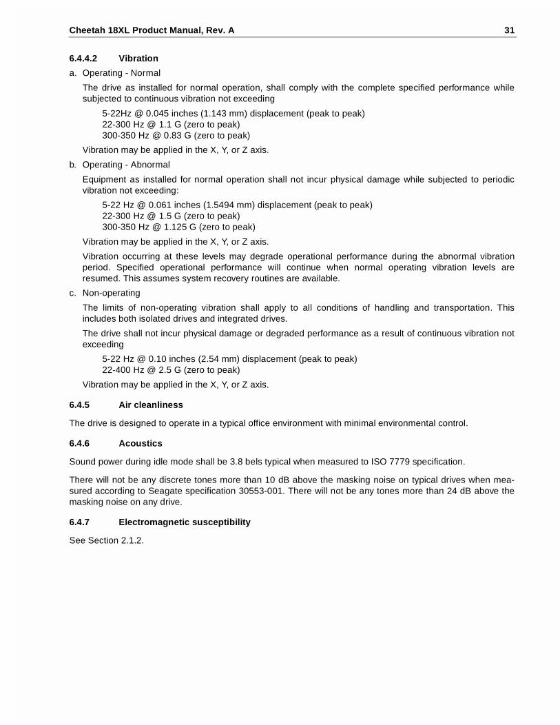
Cheetah 18XL Product Manual, Rev. A 31
6.4.4.2 Vibration
a. Operating - Normal
The drive as installed for normal operation, shall comply with the complete specified performance whilesubjected to continuous vibration not exceeding
5-22Hz @ 0.045 inches (1.143 mm) displacement (peak to peak)22-300 Hz @ 1.1 G (zero to peak)300-350 Hz @ 0.83 G (zero to peak)
Vibration may be applied in the X, Y, or Z axis.
b. Operating - Abnormal
Equipment as installed for normal operation shall not incur physical damage while subjected to periodicvibration not exceeding:
5-22 Hz @ 0.061 inches (1.5494 mm) displacement (peak to peak)22-300 Hz @ 1.5 G (zero to peak)300-350 Hz @ 1.125 G (zero to peak)
Vibration may be applied in the X, Y, or Z axis.
Vibration occurring at these levels may degrade operational performance during the abnormal vibrationperiod. Specified operational performance will continue when normal operating vibration levels areresumed. This assumes system recovery routines are available.
c. Non-operating
The limits of non-operating vibration shall apply to all conditions of handling and transportation. Thisincludes both isolated drives and integrated drives.
The drive shall not incur physical damage or degraded performance as a result of continuous vibration notexceeding
5-22 Hz @ 0.10 inches (2.54 mm) displacement (peak to peak)22-400 Hz @ 2.5 G (zero to peak)
Vibration may be applied in the X, Y, or Z axis.
6.4.5 Air cleanliness
The drive is designed to operate in a typical office environment with minimal environmental control.
6.4.6 Acoustics
Sound power during idle mode shall be 3.8 bels typical when measured to ISO 7779 specification.
There will not be any discrete tones more than 10 dB above the masking noise on typical drives when mea-sured according to Seagate specification 30553-001. There will not be any tones more than 24 dB above themasking noise on any drive.
6.4.7 Electromagnetic susceptibility
See Section 2.1.2.

32 Cheetah 18XL Product Manual, Rev. A
6.5 Mechanical specifications
The following nominal dimensions are exclusive of the decorative front panel accessory. However, dimensionsof the front panel are shown in figure below. Refer to Figures 13 and 14 for detailed mounting configurationdimensions. See Section 8.4, “Drive mounting.”
Figure 13. ST318404LW mounting configuration dimensions
Height: 1.029 in 26.1366 mmWidth: 4.015 in 101.981 mmDepth: 5.775 in 146.685 mmWeight: 1.5 pounds (ST318404) 0.680 kilograms
JH
L
B
A
S
K
[1]
M C
R
F [1]
DE
P
G
Mounting holes are 6-32 UNC 2B, three on each side and four on the bottom. Max screw penetration into side of drive is 0.15 in. (3.81 mm). Max screw tightening torque is 6.0 in-lb (3.32 nm) with minimum full thread engagement of 0.12 in. (3.05 mm).
Notes:
[1]
InchesABCDEFGHJKLMPRSTU
26.10147.00101.60
92.253.18
44.4541.2828.50
101.606.35
41.604.60
41.286.737.000.380.38
1.0285.7874.0003.750
.1251.7501.6251.1224.000
.2501.638
.1811.625
.265
.315
.015
.015
max max ± .010± .010± .010± .010± .020± .020± .010± .010± .010± .020± .020± .010± .040max max
max max ± .25
± .25 ± .25 ± .25 ± .50 ± .50 ± .25 ± .25 ± .25 ± .50 ± .50 ± .25 ± 1.02max max
Dimension TableMillimeters
-X-U
-Z-T//
-Z-
-Z-
-X-

Cheetah 18XL Product Manual, Rev. A 33
Figure 14. ST318404LC mounting configuration dimensions
A
M C
R
F [1]
DE
P
Mounting holes are 6-32 UNC 2B, three on each side and four on the bottom. Max screw penetration into side of drive is 0.15 in. (3.81 mm). Max screw tightening torque is 6.0 in-lb (3.32 nm) with minimum full thread engagement of 0.12 in. (3.05 mm).
Notes:
[1]
InchesABCDEFHJKLMNPRSTU
26.10147.00101.60
92.253.18
44.4528.50
101.606.35
41.604.601.20
41.2866.50
7.000.380.38
1.0285.7874.0003.750
.1251.7501.1224.000
.2501.638
.181
.0401.6252.618
.276
.015
.015
max max ± .010± .010± .010± .010± .020± .010± .010± .010± .020max ± .020± .010± .040max max
max max ± .25
± .25 ± .25 ± .25 ± .50 ± .25 ± .25 ± .25 ± .50 max ± .50 ± .25 ± 1.02max max
Dimension TableMillimeters-X-
-X-
U
-Z- -X-N
-Z-
JH
L
B
S
K
[1]-Z-T// -Z-


Cheetah 18XL Product Manual, Rev. A 35
7.0 Defect and error management
The drive, as delivered, complies with this specification. The read error rate and specified storage capacity arenot dependent upon use of defect management routines by the host (initiator).
Defect and error management in the SCSI system involves the drive internal defect/error management andSCSI systems error considerations (errors in communications between Initiator and the drive). Tools for use indesigning a defect/error management plan are briefly outlined in this section, with references to other sectionswhere further details are given.
7.1 Drive internal defects
During the initial drive format operation at the factory, media defects are identified, tagged as being unusable,and their locations recorded on the drive primary defects list (referred to as the “P” list and also as the ETFdefect list). At factory format time, these known defects are also reallocated, that is, reassigned to a new placeon the medium and the location listed in the defects reallocation table. The “P” list is not altered after factoryformatting. Locations of defects found and reallocated during error recovery procedures after drive shipmentare listed in the “G” list (defects growth list). The “P” and “G” lists may be referenced by the initiator using theRead Defect Data command (see the SCSI Interface Product Manual, part number 75789509).
7.2 Drive error recovery procedures
Whenever an error occurs during drive operation, the drive, if programmed to do so, performs error recoveryprocedures to attempt to recover the data. The error recovery procedures used depend on the options previ-ously set up in the error recovery parameters mode page. Error recovery and defect management may involvethe use of several SCSI commands, the details of which are described in the SCSI Interface Product Manual.The drive implements selectable error recovery time limits such as are required in video applications. For addi-tional information on this, refer to the Error Recovery Page table in the SCSI Interface Product Manual, whichdescribes the Mode Select/Mode Sense Error Recovery parameters.
The error recovery scheme supported by the drive provides a means to control the total error recovery time forthe entire command in addition to controlling the recovery level for a single LBA. The total amount of time spentin error recovery for a command can be limited via the Recovery Time Limit bytes in the Error Recovery ModePage. The total amount of time spent in error recovery for a single LBA can be limited via the Read Retry Countor Write Retry Count bytes in the Error Recovery Mode Page.
The drive firmware error recovery algorithms consist of 11 levels for read recoveries and 15 levels for writes.
Table 4 equates the Read and Write Retry Count with the maximum possible recovery time for read and writerecovery of individual LBAs. The times given do not include time taken to perform reallocations, if reallocationsare performed. Reallocations are performed when the ARRE bit (for reads) or AWRE bit (for writes) is one, theRC bit is zero, and the Recovery Time Limit for the command has not yet been met. Time needed to performreallocation is not counted against the Recovery Time Limit.
The Read Continuous (RC) bit, when set to one, requests the disc drive to transfer the requested data lengthwithout adding delays (for retries or ECC correction) that may be required to insure data integrity. The discdrive may send erroneous data in order to maintain the continuous flow of data. The RC bit should only beused when data integrity is not a concern and speed is of utmost importance. If the Recovery Time Limit orretry count is reached during error recovery, the state of the RC bit is examined. If the RC bit is set, the drivewill transfer the unrecovered data with no error indication and continue to execute the remaining command. Ifthe RC bit is not set, the drive will stop data transfer with the last good LBA, and report a “Check Condition,Unrecovered Read Error.”

36 Cheetah 18XL Product Manual, Rev. A
[1] These values are subject to change.
Setting these retry counts to a value below the default setting could result in an increased unrecoverederror rate which may exceed the value given in this product manual. A setting of zero (0) will result in thedrive not performing error recovery.
For example, suppose the Read/Write Recovery page has the RC bit set to 0, read retry count set to 4,and the recovery time limit field (Mode Sense page 01, bytes 10 and 11) set to FF FF hex (maximum). Afour LBA Read command is allowed to take up to 400.14 msec recovery time for each of the four LBAs inthe command. If the recovery time limit is set to 00 C8 hex (200 msec decimal) a four LBA read commandis allowed to take up to 200 msec for all error recovery within that command. The use of the RecoveryTime Limit field allows finer granularity on control of the time spent in error recovery. The recovery timelimit only starts counting when the drive is executing error recovery and it restarts on each command.Therefore, each command’s total recovery time is subject to the recovery time limit. Note: A recovery timelimit of 0 will use the drive’s default value of FF FF. Minimum recovery time limit is achieved by setting theRecovery Time Limit field to 00 01.
7.3 SCSI systems errors
Information on the reporting of operational errors or faults across the interface is given in the SCSI InterfaceProduct Manual, part number 75789509. Message Protocol System is described in the SCSI Interface ProductManual. Several of the messages are used in the SCSI systems error management system. The RequestSense command returns information to the host about numerous kinds of errors or faults. The Receive Diag-nostic Results reports the results of diagnostic operations performed by the drive.
Status returned by the drive to the Initiator is described in the SCSI Interface Product Manual. Status reportingplays a role in the SCSI systems error management and its use in that respect is described in sections wherethe various commands are discussed.
Table 4: Read and write retry count maximum recovery times [1]
Read retry count [1]
Maximum recovery time per LBA (cumulative, msec)
Write retry count
Maximum recovery time per LBA (cumulative, msec)
0 77.61 0 65.67
1 89.55 1 83.58
2 304.47 2 89.55
3 328.35 3 107.46
4 400.14 4 214.92
5 447.9 5 256.71
6 513.57 6 435.81
7 645.17 7 453.72
8 669.05 8 483.57
9 722.78 9 501.48
10 2182.78 10 1537.3
11 (default) 2991.88 11 1555.21
12 1561.18
13 1579.09
14 1686.55
15 (default) 1728.34

Cheetah 18XL Product Manual, Rev. A 37
8.0 InstallationNote. These drives are designed to be used only on single-ended (SE) or low voltage differential (LVD) bus-
ses. Do not install these drives on a high voltage differential (HVD) bus.
The first thing to do when installing a drive is to set the drive SCSI ID and set up certain operating options. Thisis usually done by installing small shorting jumpers on the pins of connectors J2 and J6 on the PCBA (or J1-Auxiliary on the LW model), or via the drive to host I/O signals on the LC model. Some users connect cables toJ6 or J5-Auxiliary and perform the set-up using remote switches.
Configure drive options
For option jumper locations and definitions refer to Figures 15, 16, and 17. Drive default mode parameters arenot normally needed for installation. Refer to Section 9.3.2 for default mode parameters if they are needed.
• Ensure that the SCSI ID of the drive is not the same as the host adapter. Most host adapters use SCSI ID 7because ID 7 is the highest priority on both 8 and 16 bit data buses.
• If multiple devices are on the bus set the drive SCSI ID to one that is not presently used by other devices onthe bus.
• If the drive is the only device on the bus, attach it to the end of the SCSI bus cable. The user, system integra-tor, or host equipment manufacturer must provide external terminators.
Note. For additional information about terminator requirements, refer to Sections 9.8 and 9.9.
• Set all appropriate option jumpers for desired operation prior to power on. If jumpers are changed afterpower has been applied, recycle the drive power to make the new settings effective.
• Installation instructions are provided by host system documentation or with any additionally purchased driveinstallation software. If necessary see Section 10 for Seagate support services telephone numbers.
• Do not remove the manufacturer’s installed labels from the drive and do not cover with additional labels, asthe manufacturer labels contain information required when servicing the product.
Formatting
• It is not necessary to low level format this drive. The drive is shipped from the factory low level formatted in512 byte sectors.
• Reformat the drive if a different spare sector allocation scheme is selected.• High level formatting the drive involves assigning one or more partitions or logical drives to the drive volume.
Follow the instructions in the system manuals for the system into which the drive is to be installed.
8.1 Drive ID/option select header
Figures 15 and 16 show views of the drive ID select jumper connectors. Figure 17 shows the option selectjumper connector for all models. Figure 15 shows the drive’s J5-Auxiliary jumper connector. Both J5-Auxiliaryand J6 have pins for selecting drive ID and for connecting the remote LED cable. Only one or the other shouldbe used, although using both at the same time would not damage the drive. The notes following the figuresdescribe the functions of the various jumper positions on the connectors J2, J5-Auxiliary and J6. Suggestedpart number for the jumpers used on J2 is Molex 52747-0211 (Seagate part number 77679052). A bag with thetwo jumper plug types is shipped with the standard OEM drives.

38 Cheetah 18XL Product Manual, Rev. A
Figure 15. J6 jumper header
SCSI ID = 0 (default)
Jumper Plug(enlarged toshow detail)
J6
DriveFront
Pin 1
Reserved A2A1A0
[4]
[1]
Shipped with cover installed.Do not install jumpers; retain cover.
11 9 7 5 3 1
Drive Activity LED
[4]
[6]
Dashed area is optional host circuitry (external to the drive) connected to host supplied optional usage plug. Do not connect anything to pins 13-20.
+5V
Host AlternateUsage Plug:
ReservedPins
68 4 2
[4]
ALED
RES 3
SCSI ID = 1
SCSI ID = 2
SCSI ID = 3
SCSI ID = 4
SCSI ID = 5
SCSI ID = 6
SCSI ID = 7
SCSI ID = 8
SCSI ID = 9
SCSI ID = 10
SCSI ID = 11
SCSI ID = 12
SCSI ID = 13
SCSI ID = 14
SCSI ID = 15
Ground

Cheetah 18XL Product Manual, Rev. A 39
Figure 16. J5 jumper header (on LW models only)
SCSI ID = 8
SCSI ID = 9
SCSI ID = 10
SCSI ID = 11
SCSI ID = 12
SCSI ID = 13
SCSI ID = 14
SCSI ID = 15A3 A2 A1
SCSI ID = 0 (default)
SCSI ID = 1
SCSI ID = 2
SCSI ID = 3
SCSI ID = 4
SCSI ID = 5
SCSI ID = 6
SCSI ID = 7
A0
J1-DC Power
68 PinSCSI I/O Connector
J1
J5Pin 1
[1] [2]
Drive HDA (rear view, PCB facing downward)
[2]
Pin 1
PCB
1P2P3P4P
+5V Ground
[4]
HostAlternateUsage Plug
Pins 1, 3, 5, and 7 are optional connections to switching circuits in host equipment to establish drive ID.
Remote Switches
For ID selection usejumpers as shown orconnect a cable forremote switching asshown below.
Dashed area is optional host circuitry (external to the drive) connected to host supplied optional usage plug.
[4]
Reserved
Pins 2, 4, 6, and 8 are normally not grounded. They are driven low (ground) for 250 ms after a Reset or PWR ON to allow drive toread SCSI ID selected.
A0 A1 A2 A3
11 9 7 5 3 1
12 10 8 6 4 2+5V
Drive Activity LED
+5V
N.C.
N.C.Ground

40 Cheetah 18XL Product Manual, Rev. A
Figure 17. J2 option select header
8.1.1 Notes for Figures 15, 16, and 17.
[1] Notes explaining the functions of the various jumpers on jumper header connectors J2, J5, and J6 aregiven here and in Section 8.1.2. The term “default” means as standard OEM units are configured with ajumper on those positions when shipped from factory. “Off” means no jumper is installed; “On” means ajumper is installed. OFF or ON underlined is factory default condition.
The PCBA on LC models does not have connector J5. The J5 connector signals conform to SFF-8009Revision 2.0, Unitized Connector for Cabled Drives, signal assignments for auxiliary connectors.
[2] These signals are also on 80-pin J1 I/O connector. See Tables 15 and 16.
[3] Voltage supplied by the drive.
Delay Motor Start
Enable Remote Motor Start
Write Protect
Parity Disable
Term. Power to SCSI Bus
SE
DS
ME
WP
PD
RES
RES
TP
JumperPositions
Force single-ended bus mode
(applies to “LW” model only;reserved on “LC” model)
Pin 1
Reserved
J2
J2Jumper Plug(enlarged toshow detail)
[3]
*Additional notes on these functions in section 8.1.2.
J2
DriveFront
J6

Cheetah 18XL Product Manual, Rev. A 41
8.1.2 Function description
J2jumperinstallation Jumper function description
SEOn Forces drive to use single-ended I/O drivers/receivers only.Off Drive can operate on the interface in low voltage differential mode or single-ended, depend-
ing on the voltage state of the I/O “DIFFSNS” line. Default is SE jumper not installed.
DS MEOff Off Spindle starts immediately after power up - Default setting.Off On Drive spindle does not start until Start Unit command received from host.On Off Spindle Startup is delayed by SCSI ID times 12 seconds after power is applied, i.e., drive 0
spindle starts immediately when DC power connected, drive 1 starts after 12 second delay, drive 2 starts after 24 second delay, etc.
On On Drive spindle starts when Start Unit command received from host. Delayed start feature is overridden and does not apply when ME jumper is installed.
WPOn Entire drive is write protected.Off Drive is not write protected. Default is WP jumper not installed.
PDOn Parity checking and parity error reporting by the drive is disabled.Off Drive checks for parity and reports result of parity checking to host.
Default is PD jumper not installed.
RESOff Reserved jumper position. Default is no RES jumper installed.
TP1 (Does not apply to “LC” model)Off The drive does not supply terminator power to external terminators or to the SCSI bus I/O
cable.On Drive supplies power to SCSI bus I/O cable. When drives have differential I/O circuits, a
jumper on the TP1 position may be needed to power external terminators (see system docu-mentation). These drives do not have terminator circuits on the drive.

42 Cheetah 18XL Product Manual, Rev. A
8.2 Drive orientation
The balanced rotary arm actuator design of the drive allows it to be mounted in any orientation. All drive perfor-mance characterization, however, has been done with the drive in horizontal (discs level) and vertical (drive onits side) orientations, and these are the two preferred mounting orientations.
8.3 Cooling
Cabinet cooling must be designed by the customer so that the ambient temperature immediately surroundingthe drive will not exceed temperature conditions specified in Section 6.4.1, “Temperature.” Specific consider-ation should be given to make sure adequate air circulation is present around the printed circuit board (PCB) tomeet the requirements of Section 6.4.1, “Temperature.”
8.3.1 Air flow
The rack, cabinet, or drawer environment for the drive must provide heat removal from the electronics andhead and disc assembly (HDA). You should confirm that adequate heat removal is provided using the tempera-ture measurement guidelines described in Section 6.4.1.
Forced air flow may be required to keep temperatures at or below the specified case temperatures of Table 3,in which case the drive should be oriented, or air flow directed, so that the least amount of air flow resistance iscreated while providing air flow to the electronics and HDA. Also, the shortest possible path between the airinlet and exit should be chosen to minimize the travel length of air heated by the drive and other heat sourceswithin the rack, cabinet, or drawer environment.
If forced air is determined to be necessary, possible air-flow patterns are shown in Figure 18. The air-flow pat-terns are created by one or more fans, either forcing or drawing air as shown in the illustrations. Conduction,convection, or other forced air-flow patterns are acceptable as long as the temperature measurement guide-lines of Section 6.4.1 are met.
Figure 18. Air flow (suggested)
Note. Air flows in the direction shown (front to back) or in reverse direction (back to front)
Note. Air flows in the direction shown or in reverse direction (side to side)
Above unit
Under unit
Above unit
Under unit
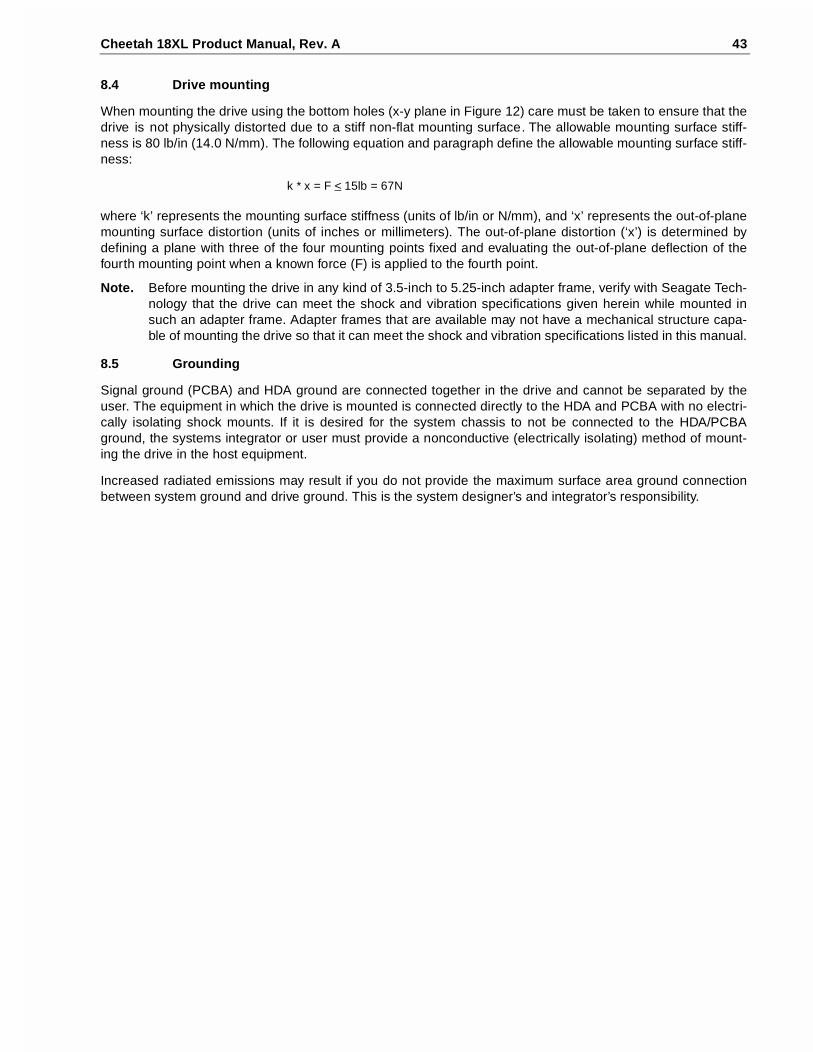
Cheetah 18XL Product Manual, Rev. A 43
8.4 Drive mounting
When mounting the drive using the bottom holes (x-y plane in Figure 12) care must be taken to ensure that thedrive is not physically distorted due to a stiff non-flat mounting surface. The allowable mounting surface stiff-ness is 80 lb/in (14.0 N/mm). The following equation and paragraph define the allowable mounting surface stiff-ness:
where ‘k’ represents the mounting surface stiffness (units of lb/in or N/mm), and ‘x’ represents the out-of-planemounting surface distortion (units of inches or millimeters). The out-of-plane distortion (‘x’) is determined bydefining a plane with three of the four mounting points fixed and evaluating the out-of-plane deflection of thefourth mounting point when a known force (F) is applied to the fourth point.
Note. Before mounting the drive in any kind of 3.5-inch to 5.25-inch adapter frame, verify with Seagate Tech-nology that the drive can meet the shock and vibration specifications given herein while mounted insuch an adapter frame. Adapter frames that are available may not have a mechanical structure capa-ble of mounting the drive so that it can meet the shock and vibration specifications listed in this manual.
8.5 Grounding
Signal ground (PCBA) and HDA ground are connected together in the drive and cannot be separated by theuser. The equipment in which the drive is mounted is connected directly to the HDA and PCBA with no electri-cally isolating shock mounts. If it is desired for the system chassis to not be connected to the HDA/PCBAground, the systems integrator or user must provide a nonconductive (electrically isolating) method of mount-ing the drive in the host equipment.
Increased radiated emissions may result if you do not provide the maximum surface area ground connectionbetween system ground and drive ground. This is the system designer’s and integrator’s responsibility.
k * x = F < 15lb = 67N


Cheetah 18XL Product Manual, Rev. A 45
9.0 Interface requirements
This section partially describes the interface requirements as implemented on the drives.
9.1 General description
This section describes in essentially general terms the interface requirements supported by the Cheetah 18XL.No attempt is made to describe all of the minute details of conditions and constraints that must be consideredby designers when designing a system in which this family of drives can properly operate. Seagate declaresthat the drives operate in accordance with the appropriate ANSI Standards referenced in various places herein,with exceptions as noted herein or in the Seagate SCSI Interface Product Manual, part number 75789509.
9.2 SCSI interface messages supported
Table 5 lists the messages supported by the SCSI-2 and SCSI-3 modes of the Cheetah 18XL family drives.
Table 5: SCSI messages supported by Cheetah 18XL family drives
Message name Message codeSupported bySCSI-2/3
Abort 06h Y
Abort-tag 0Dh Y
Bus device reset 0Ch Y
Clear ACA 16h N
Clear queue 0Eh Y
Command complete 00h Y
Continue I/O process 12h Y
Disconnect 04h Y
Extended messages 01h[1] Y
Identify 80h-FFh Y
Ignore wide residue (two bytes) 23h Y
Initiate recovery 0Fh N
Initiator detected error 05h Y
Linked command complete 0Ah Y
Linked command complete with flag 0Bh Y
Message parity error 09h Y
Message reject 07h Y
Modify data pointer [1] N
No operation 08h Y
Parallel Protocol Request [1] [2] Y
Queue tag messages (two bytes)
ACA 24h N
Head of queue tag 21h Y
Ordered queue tag 22h Y
Simple queue tag 20h Y
Release recovery 10h N
Restore pointers 03h Y
Save data pointer 02h Y
Synchronous data transfer req. [1] Y
Target transfer disable 13h Y
Terminate I/O process 11h Y
Wide data transfer request [1] Y

46 Cheetah 18XL Product Manual, Rev. A
Notes.[1] Extended messages (see the SCSI Interface Product Manual, part number 75789509).[2] Supports all options except qas_req and iu_req.
9.3 SCSI interface commands supported
Table 6 following lists the SCSI interface commands that are supported by the drive. Cheetah 18XL Familydrives can be changed back and forth between SCSI-1, SCSI-2, and SCSI-3 (Ultra160) modes using theChange Definition Command. OEM standard drives are shipped set to operate in Ultra160 mode.
Table 6: Commands supported by Cheetah 18XL family drive
Command nameCommandcode
Supported by SCSI-2/3
Change definition 40h NCompare 39h NCopy 18h NCopy and verify 3Ah NFormat unit [1] 04h Y DPRY bit supported N DCRT bit supported Y STPF bit supported Y IP bit supported Y DSP bit supported Y IMMED bit supported Y VS (vendor specific) NInquiry 12h YDate code page (C1h) YFirmware numbers page (C0h) YImplemented operating def page (81h) YJumper settings page (C2h) YSupported Vital product data page (00h) YUnit serial number page (80h) Y
Lock-unlock cache 36h NLog select 4Ch YPCR bit YDU bit NDS bit YTSD bit YETC bit NTMC bit NLP bit N
Log sense 4Dh YApplication client log page (0Fh) YCache statistics page (37h) Y
Factory log page (3Eh) YNon-medium error page (06h) YPages supported list (00h) YRead error counter page (03h) YSelf-test results page (10h) YStart-stop cycle counter page (0Eh) YTemperature page (0Dh) YVerify error counter page (05h) YWrite error counter page (02h) Y

Cheetah 18XL Product Manual, Rev. A 47
Factory log page (3Eh) YMode select (same pages as Mode Sense 1Ah) 15h Y [2]Mode select (10) (same pages as Mode Sense 1Ah) 55h YMode sense 1Ah Y [2]Caching parameters page (08h) YControl mode page (0Ah) YDisconnect/reconnect (02h) YError recovery page (01h) YFormat page (03h) Y
Information exceptions control page (1Ch) YNotch and Partition Page (0Ch) NPower condition page (1Ah) YRigid disc drive geometry page (04h) YUnit attention page (00h) YVerify error recovery page (07h) Y
Xor Control page (10h) NMode sense (10) (same pages as Mode Sense 1Ah) 5Ah YPrefetch 34h NRead 08h YRead buffer (modes 0, 2, 3, Ah and Bh supported) 3Ch YRead capacity 25h YRead defect data (10) 37h YRead defect data (12) B7h YRead extended 28h Y DPO bit supported Y FUA bit supported YRead long 3Eh YReassign blocks 07h YReceive diagnostic results 1Ch YSupported diagnostics pages (00h) YTranslate page (40h) Y
Release 17h YRelease (10) 57h YRequest sense 03h YActual retry count bytes YExtended sense YField pointer bytes Y
Reserve 16h Y3rd party reserve YExtent reservation N
Reserve (10) 56h Y 3rd part reserve Y Extent reservation NRezero unit 01h YSearch data equal 31h NSearch data high 30h NSearch data low 32h N
Table 6: Commands supported by Cheetah 18XL family drive (Continued)
Command nameCommandcode
Supported by SCSI-2/3

48 Cheetah 18XL Product Manual, Rev. A
[1] The drive can format to any even number of bytes per sector from 512 to 4,096.[2] Tables 8 and 9 show how individual bits are set and which are changeable by the host.[3] WARNING: A power loss during flash programming can result in firmware corruption. This usually makes
the drive inoperable.
Seek 0Bh YSeek extended 2Bh YSend diagnostics 1Dh YSupported diagnostics pages (00h) YTranslate page (40h) Y
Set limits 33h NStart unit/stop unit (spindle ceases rotating) (1Ch) 1Bh YSynchronize cache 35h YTest unit ready 00h YVerify 2Fh Y BYTCHK bit YWrite 0Ah YWrite and verify 2Eh Y DPO bit YWrite buffer (modes 0, 2, supported) 3Bh Y Firmware download option (modes 5, 7, Ah and Bh supported) [3]
Y
Write extended 2Ah Y DPO bit Y FUA bit YWrite long 3Fh YWrite same 41h Y PBdata N LBdata NXDRead 52h NXDWrite 50h NXPWrite 51h N
Table 6: Commands supported by Cheetah 18XL family drive (Continued)
Command nameCommandcode
Supported by SCSI-2/3

Cheetah 18XL Product Manual, Rev. A 49
Table 7 lists the Standard Inquiry command data that the drive should return to the initiator per the format givenin the SCSI Interface Product Manual, part number 75789509, Inquiry command section.
[ ]1 03 means SCSI-3 (Ultra160) implemented.
[ ]2 02 means response data in SCSI-3 (Ultra160) format. In addition, 12 indicates that the drive uses the hier-archical addressing mode to assign LUNs to logical units (default is 12).
R# Four ASCII digits representing the last four digits of the product Firmware Release number. This informa-tion is also given in the Vital Product Data page C0h, together with servo RAM and ROM release num-bers.
S# Eight ASCII digits representing the eight digits of the product serial number.
[ ]3 Bytes 18 through 24 reflect model of drive. Shown here are hex values for Model ST318404LW.
For “LW” models, bytes 23 and 24 are 4C 57.For “LC” models, bytes 23 and 24 are 4C 43.
[ ]5 Copyright Year - changes with actual year.
9.3.1 Inquiry Vital Product data
Instead of the standard Inquiry data shown in Table 7, the initiator can request several Vital Product Datapages by setting the Inquiry command EVPD bit to one. The SCSI Interface Product Manual, part number75789509, lists the Vital Product Data pages and describes their formats. A separate Inquiry command mustbe sent to the drive for each Vital Product Data page the initiator wants the drive to send back.
Table 7: Cheetah 18XL family drive Standard Inquiry data
Bytes Data (HEX)
0-15 00 00 [03]1 [12]2 8B 00 [01] [3E] 53 45 41 47 41 54 45 20 VENDOR ID
16-31 53 54 [33] [31] [34] [30] [34] [4C] [57]3 20 20 20 20 20 20 20 PRODUCT ID
32-47 R# R# R# R# S# S# S# S# S# S# S# S# 00 00 00 00
48-63 00 00 00 00 00 00 00 00 00 00 00 00 00 00 00 00
64-79 00 00 00 00 00 00 00 00 00 00 00 00 00 00 00 00
80-95 00 00 00 00 00 00 00 00 00 00 00 00 00 00 00 00
96-111 00 43 6F 70 79 72 69 67 68 74 20 28 63 29 20 [31] COPYRIGHT
112-127 [39] [39] [39]5 20 53 65 61 67 61 74 65 20 41 6C 6C 20 NOTICE
128-143 72 69 67 68 74 73 20 72 65 73 65 72 76 65 64 20

50 Cheetah 18XL Product Manual, Rev. A
9.3.2 Mode Sense data
The Mode Sense command provides a means for the drive to report its operating parameters to the initiator.The drive maintains four sets of Mode parameters, Default values, Saved values, Current values and Change-able values.
Default values are hard coded in the drive firmware that is stored in flash EPROM nonvolatile memory on thedrive PCBA. Default values can be changed only by downloading a complete set of new firmware into the flashEPROM. An initiator can request and receive from the drive a list of default values and use those in a ModeSelect command to set up new current and saved values, where the values are changeable.
Saved values are stored on the disk media using a Mode Select command. Only parameter values that areallowed to be changed can be changed by this method. See “Changeable values” defined below. Parameters inthe saved values list that are not changeable by the Mode Select command get their values from the defaultvalues storage.
Current values are volatile values currently being used by the drive to control its operation. A Mode Select com-mand can be used to change these values (only those that are changeable). Originally, they are installed fromsaved or default values after a power on reset, hard reset, or Bus Device Reset message.
Changeable values form a bit mask, stored in nonvolatile memory, that dictates which of the current values andsaved values can be changed by a Mode Select command. A “one” allows a change to a corresponding bit; a“zero” allows no change. For example, in Table 8 refer to Mode page 01, in the row entitled “CHG”. These arehex numbers representing the changeable values for mode page 01. Note that bytes 04, 05, 06, and 07 are notchangeable, because those fields are all zeros. If some changeable code had a hex value EF, that equates tothe binary pattern 1110 1111. If there is a zero in any bit position in the field, it means that bit is not change-able. Bits 7, 6, 5, 3, 2, 1, and 0 are changeable, because those bits are all ones. Bit 4 is not changeable.
Though the drive always reports non-zero values in bytes 00 and 01, those particular bytes are never change-able.
The Changeable values list can only be changed by downloading new firmware into the flash EPROM.
On standard OEM drives the Saved values are taken from the default values list and stored into the saved val-ues storage location on the media prior to shipping.
When a drive is powered up, it takes saved values from the media and stores them to the current values stor-age in volatile memory. It is not possible to change the current values (or the saved values) with a Mode Selectcommand before the drive is up to speed and is “ready.” An attempt to do so results in a “Check Condition sta-tus being returned.
Note. Because there may be several different versions of drive control firmware in the total population ofdrives in the field, the Mode Sense values given in the following tables may not exactly match those ofsome drives.

Cheetah 18XL Product Manual, Rev. A 51
The following tables list the values of the data bytes returned by the drive in response to the Mode Sense com-mand pages for SCSI Ultra160 implementation (see the SCSI Interface Product Manual, part number75789509).
Definitions:
SAV = Saved value.DEF = Default value. Standard drives are shipped configured this way.CHG= Changeable bits; indicates if current and saved values are changeable.
Note. Saved values for OEM drives are normally the same as the default values.

52 Cheetah 18XL Product Manual, Rev. A
Table 8: Mode sense data, ST318404 values
[1] Though byte 12, bit 7 (A0) is shown as changeable, the FSW function governed by that bit is not imple-mented by this drive.
[2] Page 0, Byte 2, Bit 7 is defined as the Performance Mode (PM) bit. When set to zero (Server mode), theSCSI firmware is performance optimized for server applications. When the bit is set to one (Desktop
Bytes 00 01 02 03 04 05 06 07 08 09 10 11 12 13 14 15 16 17 18 19 20 21 22 23
ModeSenseData 9F 00 10 08 02 22 EE 56 00 00 02 00
ModePage
<------------------------------Mode Page Headers and Parameter Data Bytes---------------------------->
01 SAV 81 0A C0 0B F0 00 00 00 0F 00 FF FF
01 DEF 81 0A C0 0B F0 00 00 00 0F 00 FF FF
01 CHG 00 0A FF FF 00 00 00 00 FF 00 FF FF
02 SAV 82 0E 80 80 00 0A 00 00 00 00 00 00 00 00 00 00
02 DEF 82 0E 80 80 00 0A 00 00 00 00 00 00 00 00 00 00
02 CHG 00 0E FF FF 00 00 00 00 00 00 00 00 87 00 00 00
03 SAV 83 16 14 76 00 00 00 0f 00 00 01 A5 02 00 00 01 00 4B 00 55 40 00 00 00
03 DEF 83 16 14 76 00 00 00 0f 00 00 01 A5 02 00 00 01 00 4B 00 55 40 00 00 00
03 CHG 00 16 00 00 00 00 00 00 00 00 00 00 00 00 00 00 00 00 00 00 00 00 00 00
04 SAV 84 16 00 38 30 06 00 00 00 00 00 00 00 00 00 00 00 00 00 00 27 20 00 00
04 DEF 84 16 00 38 30 06 00 00 00 00 00 00 00 00 00 00 00 00 00 00 27 20 00 00
04 CHG 00 16 00 00 00 00 00 00 00 00 00 00 00 00 00 00 00 00 00 00 00 00 00 00
07 SAV 87 0A 00 0B F0 00 00 00 00 00 FF FF
07 DEF 87 0A 00 0B F0 00 00 00 00 00 FF FF
07 CHG 00 0A 0F FF 00 00 00 00 00 00 FF FF
08 SAV 88 12 14 00 FF FF 00 00 FF FF FF FF 80 03[3] 00 00 00 00 00 00
08 DEF 88 12 14 00 FF FF 00 00 FF FF FF FF 80 03[3] 00 00 00 00 00 00
08 CHG 00 12 B5 00 00 00 FF FF FF FF 00 00 A0 FF 00 00 00 00 00 00
0A SAV 8A 0A 02 00 00 00 00 00 00 00 02 B3
0A DEF 8A 0A 02 00 00 00 00 00 00 00 02 B3
0A CHG 00 0A 03 F1 00 00 00 00 00 00 00 00
1A SAV 9A 0A 00 03 00 00 00 01 00 00 00 04
1A DEF 9A 0A 00 03 00 00 00 01 00 00 00 04
1A CHG 00 0A 00 03 00 00 00 00 00 00 00 00
1C SAV 9C 0A 00 00 00 00 00 00 00 00 00 01
1C DEF 9C 0A 00 00 00 00 00 00 00 00 00 01
1C CHG 00 0A 8D 0F FF FF FF FF FF FF FF FF
00 SAV 80 02 00[2] 00
00 DEF 80 02 00[2] 00
00 CHG 00 02 FF 40
Read capacity data
02 22 EE 55 00 00 02 00

Cheetah 18XL Product Manual, Rev. A 53
mode), the SCSI firmware is performance optimized for desktop applications. The firmware default condi-tion for the PM bit is set to one for Desktop mode. During the manufacturing process, the Saved value ofthe PM bit remains set to the firmware default condition (one) for drives with the LW interface. Drives man-ufactured with all other interfaces (LC) set the Saved value of the PM bit set to the Server mode (zero).
[3] When the Performance Mode bit (Page 0, Byte 2, Bit 7) is set to Server mode (zero), the Number ofCache Segments should be set to sixteen (10h).

54 Cheetah 18XL Product Manual, Rev. A
Table 9: Mode sense data, ST39204 values
[1] Though byte 12, bit 7 (A0) is shown as changeable, the FSW function governed by that bit is not imple-mented by this drive.
[2] Page 0, Byte 2, Bit 7 is defined as the Performance Mode (PM) bit. When set to zero (Server mode), theSCSI firmware is performance optimized for server applications. When the bit is set to one (Desktop
Bytes 00 01 02 03 04 05 06 07 08 09 10 11 12 13 14 15 16 17 18 19 20 21 22 23
ModeSenseData 9F 00 10 08 01 11 77 2B 00 00 02 00
ModePage
<------------------------------Mode Page Headers and Parameter Data Bytes---------------------------->
01 SAV 81 0A C0 0B F0 00 00 00 0F 00 FF FF
01 DEF 81 0A C0 0B F0 00 00 00 0F 00 FF FF
01 CHG 00 0A FF FF 00 00 00 00 FF 00 FF FF
02 SAV 82 0E 80 80 00 0A 00 00 00 00 00 00 00 00 00 00
02 DEF 82 0E 80 80 00 0A 00 00 00 00 00 00 00 00 00 00
02 CHG 00 0E FF FF 00 00 00 00 00 00 00 00 87 00 00 00
03 SAV 83 16 0A 3B 00 00 00 0F 00 00 01 A5 02 00 00 01 00 4B 00 55 40 00 00 00
03 DEF 83 16 0A 3B 00 00 00 0F 00 00 01 A5 02 00 00 01 00 4B 00 55 40 00 00 00
03 CHG 00 16 00 00 00 00 00 00 00 00 00 00 00 00 00 00 00 00 00 00 00 00 00 00
04 SAV 84 16 00 38 30 03 00 00 00 00 00 00 00 00 00 00 00 00 00 00 27 20 00 00
04 DEF 84 16 00 38 30 03 00 00 00 00 00 00 00 00 00 00 00 00 00 00 27 20 00 00
04 CHG 00 16 00 00 00 00 00 00 00 00 00 00 00 00 00 00 00 00 00 00 00 00 00 00
07 SAV 87 0A 00 0B F0 00 00 00 00 00 FF FF
07 DEF 87 0A 00 0B F0 00 00 00 00 00 FF FF
07 CHG 00 0A 0F FF 00 00 00 00 00 00 FF FF
08 SAV 88 12 14 00 FF FF 00 00 FF FF FF FF 80 03[3] 00 00 00 00 00 00
08 DEF 88 12 14 00 FF FF 00 00 FF FF FF FF 80 03[3] 00 00 00 00 00 00
08 CHG 00 12 B5 00 00 00 FF FF FF FF 00 00 A0 FF 00 00 00 00 00 00
0A SAV 8A 0A 02 00 00 00 00 00 00 00 01 A3
0A DEF 8A 0A 02 00 00 00 00 00 00 00 01 A3
0A CHG 00 0A 03 F1 00 00 00 00 00 00 00 00
1A SAV 9A‘ 0A 00 03 00 00 00 01 00 00 00 04
1A DEF 9A‘ 0A 00 03 00 00 00 01 00 00 00 04
1A CHG 00 0A 00 03 00 00 00 00 00 00 00 00
1C SAV 9C 0A 00 00 00 00 00 00 00 00 00 01
1C DEF 9C 0A 00 00 00 00 00 00 00 00 00 01
1C CHG 00 0A 8D 0F FF FF FF FF FF FF FF FF
00 SAV 80 02 00[2] 00
00 DEF 80 02 00[2] 00
00 CHG 00 02 FF 40
Read capacity data
01 11 77 2A 00 00 02 00

Cheetah 18XL Product Manual, Rev. A 55
mode), the SCSI firmware is performance optimized for desktop applications. The firmware default condi-tion for the PM bit is set to one for Desktop mode. During the manufacturing process, the Saved value ofthe PM bit remains set to the firmware default condition (one) for drives with the LW interface. Drives man-ufactured with all other interfaces (LC) set the Saved value of the PM bit set to the Server mode (zero).
[3] When the Performance Mode bit (Page 0, Byte 2, Bit 7) is set to Server mode (zero), the Number ofCache Segments should be set to sixteen (10h).

56 Cheetah 18XL Product Manual, Rev. A
9.4 SCSI bus conditions and miscellaneous features supported
Asynchronous SCSI bus conditions supported by the drive are listed below. These conditions cause the SCSIdevice to perform certain actions and can alter the SCSI bus phase sequence. Other miscellaneous operatingfeatures supported are also listed here. Refer to the SCSI Interface Product Manual, part number 75789509,for details.
Table 10: SCSI bus conditions and other miscellaneous features
Condition/features supported:
SCSI-2/SCSI-3 Conditions or feature
Y Adaptive Caching
Y Arbitrating System
Y Asynchronous Data Transfer
N Asynchronous Event Notification
Y Attention Condition
N Auto Contingent Allegiance Condition
Y Contingent Allegiance Condition
Y Deferred Error Handling
Y Disconnect/Reconnect
N High voltage differential (HVD) interface available
Y Low voltage differential (LVD) interface available
Y Parameter Rounding (controlled by the Round bit in Mode Select page 0)
Y Queue tagging (up to 64 Queue tags supported)
Y Reporting actual retry count in Extended Sense bytes 15, 16 and 17.
Y Reset Condition
Y Segmented Caching
Y Synchronous Data Transfer
N Zero Latency Read
SCSI-2/SCSI-3 Status supported
Y Good
Y Check Condition
Y Condition Met/Good
Y Busy
Y Intermediate/Good
Y Intermediate/Condition Met/Good
Y Reservation Conflict
Y Queue Full
N ACA Active

Cheetah 18XL Product Manual, Rev. A 57
9.5 Synchronous data transfer
9.5.1 Synchronous data transfer periods supported
Table 11 and Section 9.5.2 list Synchronous Data transfer periods supported by the drive. The data transferperiod to be used by the drive and the initiator is established by an exchange of messages during the MessagePhase of operation. See the section on message protocol in the SCSI Interface Product Manual, part number75789509.
Table 11: Synchronous data transfer periods
9.5.2 REQ/ACK offset
The maximum value supported by the Cheetah 18XL family drives for REQ/ACK offset is 63 (3Fh).
9.6 Physical interface
This section describes the connectors, cables, signals, terminators and bus timing of the DC and SCSI I/Ointerface. See Section 9.8 and Section 9.9 for additional terminator information.
Figures 19 and 20 show the locations of the DC power connector, SCSI interface connector, drive select head-ers, and option select headers.
Details of the physical, electrical and logical characteristics are given in sections following, while the SCSIoperational aspects of Seagate drive interfaces are given in the SCSI Interface Product Manual, part number75789509.
9.6.1 DC cable and connector
ST318404LW drives receive DC power through a 4 pin connector (see Figure 21 for pin assignment) mountedat the rear of the main PCBA. Recommended part numbers of the mating connector are listed below, but equiv-alent parts may be used.
LC model drives receive power through the 80-pin I/O connector. See Tables 15 and 16.
M (decimal)Transfer period (nanoseconds)
Transfer rate (megatransfers/second)
10 25 40.01
1. This transfer rate is only allowed when using the LVD interface.
12 50 20.0
25 100 10.0
50 200 5.0
Type of cable Connector Contacts (20-14 AWG)
14 AWG MP 1-480424-0 AMP 60619-4 (Loose Piece)AMP 61117-4 (Strip)
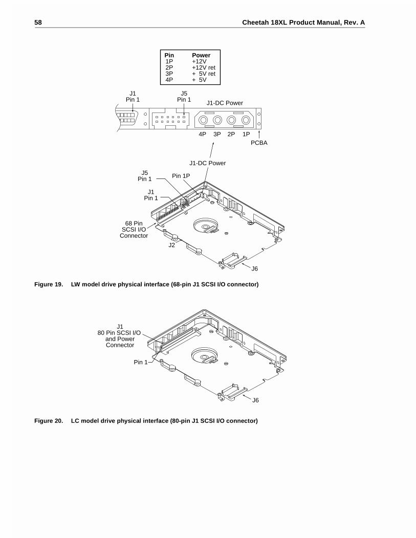
58 Cheetah 18XL Product Manual, Rev. A
Figure 19. LW model drive physical interface (68-pin J1 SCSI I/O connector)
Figure 20. LC model drive physical interface (80-pin J1 SCSI I/O connector)
J5Pin 1
68 PinSCSI I/O
Connector
Pin 1P
J1-DC Power
J6
J1Pin 1
J1-DC Power
Pin1P2P3P4P
Power+12V+12V ret+ 5V ret+ 5V
J1Pin 1
1P2P3P4P
J5Pin 1
PCBA
J2
J180 Pin SCSI I/O
and PowerConnector
Pin 1
J6

Cheetah 18XL Product Manual, Rev. A 59
9.6.2 SCSI interface physical description
The drive models described by this product manual support the physical interface requirements of the Ultra160SCSI Parallel Interface-3 (SPI-3) standards as defined in American National Standard document X3T10/1302Drevision 14, and operate compatibly at the interface with devices that support earlier SCSI-2 and SCSI-3 stan-dards. It should be noted that this is only true if the systems engineering has been correctly done, and if earlierSCSI-2 and SCSI-3 devices respond in an acceptable manner (per applicable SCSI Standards) to reject newerUltra160 SCSI protocol extensions that they don’t support.
The drives documented in this manual support single-ended and low voltage differential physical interconnects(hereafter referred to as SE and LVD, respectively) as described in the ANSI SPI-3 standard. These drivesimplement driver and receiver circuits that can operate either SE or LVD. However, they cannot switch dynami-cally between SE and LVD operation.
The drives typically operate on a daisy-chain interface in which other SCSI devices are also operating. Deviceson the daisy chain must all operate in the same mode, either SE or LVD, but not a mixture of these. On theinterface daisy chain, all signals are common between all devices on the chain, or bus, as it is also called. Thisdaisy chain of SCSI devices must be terminated at both ends with the proper impedance in order to operatecorrectly. Do not terminate intermediate SCSI devices. In some cases, the SCSI devices at each end haveonboard termination circuits that can be enabled by installation of a jumper plug (TE) on the device. These ter-mination circuits receive power from either a source internal to the device, or from a line in the interface cablespecifically powered for that purpose. LC and LW model drives do not have onboard termination circuits. Sometype of external termination circuits must be provided for these drives by the end user or designers of theequipment into which the drives will be integrated. See Standard X3T10/1302D, sections 6.4 and 6.5 for themaximum number of devices that can successfully operate at various interface transfer rates on SE and LVDdaisy chains.
“LC” model drives plug into PCBA or bulkhead connectors in the host. They may be connected in a daisy-chainby the host backplane wiring or PCBA circuit runs that have adequate DC current carrying capacity to supportthe number of drives plugged into the PCBA or bulkhead connectors. A single 80-pin I/O connector cable can-not support the DC current needs of several drives, so no daisy chain cables beyond the bulkhead connectorsshould be used. A single drive connected via a cable to a host 80-pin I/O connector is not recommended.
Table 12 shows the interface transfer rates supported by the various drive models defined in this manual.
Table 12: Interface transfer rates supported
9.6.3 SCSI interface cable requirements
The characteristics of cables used to connect Ultra160 SCSI parallel interface devices are discussed in detailin section 6 of ANSI Standard X3T10/1302D. The cable characteristics that must be considered when intercon-necting the drives described in this manual in a Ultra160 SCSI parallel, daisy-chain interconnected system are:
• characteristic impedance (see Section 6.1)• propagation delay (see Section 6.1)• cumulative length (see Sections 6.4 and 6.5)• stub length (see Sections 6.4 and 6.5)• device spacing (see Sections 6.4 and 6.5)
To minimize discontinuances and signal reflections, cables of different impedances should not be used in thesame bus. Implementations may require trade-offs in shielding effectiveness, cable length, number of loads
Interface type/drive models
Maximum transfer rate
Asynchronous Fast-5 Fast-10 Fast-20 Fast-40 Fast-80
SE ST318404LW/LCST39204LW/LC
yes yes yes yes no no
LVD ST318404LW/LCST39204LW/LC
yes yes yes yes yes yes

60 Cheetah 18XL Product Manual, Rev. A
and spacing, transfer rates, and cost to achieve satisfactory system operation. If shielded and unshieldedcables are mixed within the same SCSI bus, the effect of impedance mismatch must be carefully considered.Proper impedance matching is especially important in order to maintain adequate margin at FAST-20 andFAST-40 SCSI transfer rates.
Note. For LVD operation, twisted pair cables are recommended. For LVD Fast-40 operation, twisted paircables are strongly recommended. For Fast-80 operation, twisted pair cables are required.
ST318404LC/ST39204LC:
The 80-pin connector option is intended for use on drives that plug directly into backplane connector in the hostequipment. In such installations, all backplane wiring segments are subject to the electromagnetic conceptspresented in Standard X3T10/1302D, section 6. For LC model drives, installations with connectors on cablesare not recommended.
9.6.4 Mating connectors
Part numbers for the different type connectors that mate with the various Cheetah 18XL I/O connectors aregiven in the sections following.
9.6.4.1 Mating connectors for LW model drives
The nonshielded cable connector shall be a 68 conductor connector consisting of two rows of 34 male contactswith adjacent contacts 0.050 inch (1.27 mm) apart.
Recommended mating flat cable connector part numbers are:
[1] See Figure 21.
The drive device connector is a nonshielded 68 conductor connector consisting of two rows of 34 female pinswith adjacent pins 50 mils apart. The connector is keyed by means of its shape (see Figure 22).
9.6.4.2 Mating connectors for LC model drives
The nonshielded connector shall be an 80-conductor connector consisting of two rows of 40 contacts with adja-cent contacts 50 (1.27 mm) mils apart (see Figure 23). I/O connection using a cable is not recommended. Thelength and size of the host equipment DC power carrying conductors from the DC power source to the hostequipment 80-pin disk drive interface connector(s) should be strictly designed according to proper power trans-mission design concepts. No possibility for the equipment user to attach an 80-pin cable/connector should beallowed, since the length of the DC power carrying conductors could not be controlled and therefore couldbecome too long for safe power transmission to the drive. Daisy-chain 80-conductor cables should especiallynot be allowed, since the power-carrying conductors on the 80-conductor interface were not intended to sup-port a series of drives.
To insure that both drive connector and host equipment mating connector mate properly, both drive connectorand host equipment mating connector must meet the provisions of “SFF-8046 Specification for 80-pin connec-tor for SCSI Disk Drives.”
Amp Model 786096-7 Female, 68-pin, panel mount
Amp Model 786090-7 Female, 68-pin, cable mount
Amp Model 749925-5 (50 mil conductor centers, 28 or 30 AWG wire) Use two, 34 conductor, 50 mil center flat cable with this connector. This type connector can only be used on cable ends. [1]
Amp Model 88-5870-294-5 W/O Strain Relief (25 mil conductor centers, 30 AWG wire).Use either on cable ends or in cable middle section for daisy-chain installations [1].
Amp Model 1-480420-0 Power connector 4 circuit housing
Berg 69307-012 12-position, 2 x 6, 2 mm receptacle housing

Cheetah 18XL Product Manual, Rev. A 61
Recommended mating 80-position PCBA mount connectors:
Right-angle to PCBA connectors
Seagate P/N: 77678559 Amp US P/N: 2-557101-1 Amp Japan P/N: 5-175474-9
For additional information call Amp FAX service at 1-800-522-6752.
[1] Closed end type 68-pin connector used. Terminators enabled.[2] Open end type (in-line application) connector used.[3] Host need not be on the end of the daisy-chain. Another device can be on the end with the terminator, the
host having no terminator.[4] Total interface cable length must not exceed that specified in ANSI document X3T10/1302D (including
host adapter/initiator). The cable length restriction limits the total number of devices allowed.[5] SCSI ID7 has highest arbitration priority, then ID15 to ID8 (ID 8 very lowest).[6] Last drive on the daisy chain.[7] Open-end type 68-pin connector used. If end device, use external terminator and closed-end type 68-pin
connector.
Figure 21. SCSI daisy chain interface cabling for LW drives
Straight-in connector Hot plug version (with ground guide-pin)
Seagate P/N: 77678703Amp US P/N: or
2-557103-194-0680-02-1
787311-1 with polarization
Amp US P/N: or
2-557103-294-0680-02-2
787311-2 without polarization
Amp Japan P/N: 5-175475-9
Host AdapterPCBA
Pin 1(check your
adapter for Pin 1 location)
[6]
SCSI ID 1
SCSI ID 0
SCSI ID 7 [5]
2 through XSCSI devices [4]
[1]
[1]
[3][2]
Terminator
“LW” ModelDrive Note. Do not mix drives operating
single-ended with drives operating differential on the daisy chain.
[2]
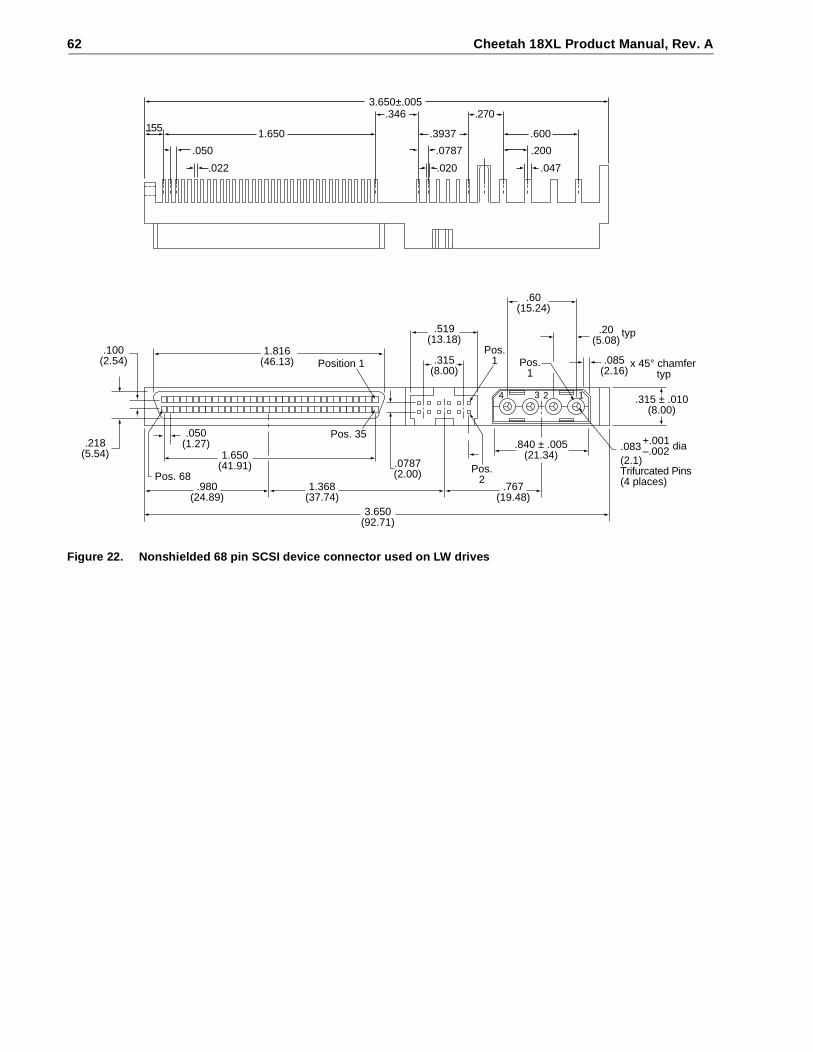
62 Cheetah 18XL Product Manual, Rev. A
Figure 22. Nonshielded 68 pin SCSI device connector used on LW drives
.0787(2.00)
.519(13.18)
.315(8.00)
3.650(92.71)
.840 ± .005(21.34)
.315 ± .010(8.00)
+.001–.002 dia.083
(2.1)Trifurcated Pins(4 places)
.085(2.16)
x 45° chamfer typ
.20(5.08)
typ
.60(15.24)
.100(2.54)
Pos.1
Pos.2
1234
1.816(46.13) Position 1
Pos. 68
Pos. 35
1.650(41.91)
.980(24.89)
1.368(37.74)
.767(19.48)
.050(1.27).218
(5.54)
Pos.1
.022
.050
.020 .047
.0787 .200
1.650 .3937 .600
.3463.650±.005
.270.155

Cheetah 18XL Product Manual, Rev. A 63
Figure 23. Nonshielded 80 pin SCSI “SCA-2” connector, used on LC drives
7.00(.276)
12.70(.500)
2.15±0.102 places
57.87(2.278)
–Y–
0.15 M Y M
0.15 M Y M
0–0.15+ .000– .006[ [
62.15(2.447)
± 0.15(± .005)
HousingX
XContact
0.3(.012)M Y M
1.27(.05)Typ
CL of Datum Y
CL of Datum Y
0.50(.020)
Pin 1 Pin 40
Pin 41 Pin 80
Pin 1
Front View
End View
Top View
Back View
Insert matingI/O connector
GroundingPins
GroundingPins

64 Cheetah 18XL Product Manual, Rev. A
Table 13: LW 68-conductor single-ended (SE) P cable signal/pin assignments [11]
Note. A minus sign preceding a signal name indicates that signal is active low.
Notes [ ]: See page following Table 16.
Signalname [1]
Connectorcontactnumber [3]
Cable conductor number [2]
Connectorcontactnumber [3]
Signalname [1]
GND 1 1 2 35 –DB12GND 2 3 4 36 –DB13GND 3 5 6 37 –DB14GND 4 7 8 38 –DB15GND 5 9 10 39 –DBP1GND 6 11 12 40 –DB0GND 7 13 14 41 –DB1GND 8 15 16 42 –DB2GND 9 17 18 43 –DB3GND 10 19 20 44 –DB4GND 11 21 22 45 –DB5GND 12 23 24 46 –DB6GND 13 25 26 47 –DB7GND 14 27 28 48 –DBPGND 15 29 30 49 GNDGND 16 31 32 50 GNDTermPwr 17 33 34 51 TermPwrTermPwr 18 35 36 52 TermPwrReserved 19 37 38 53 ReservedGND 20 39 40 54 GNDGND 21 41 42 55 –ATNGND 22 43 44 56 GNDGND 23 45 46 57 –BSYGND 24 47 48 58 –ACKGND 25 49 50 59 –RSTGND 26 51 52 60 –MSGGND 27 53 54 61 –SELGND 28 55 56 62 –C/DGND 29 57 58 63 –REQGND 30 59 60 64 –I/OGND 31 61 62 65 –DB8GND 32 63 64 66 –DB9GND 33 65 66 67 –DB10GND 34 67 68 68 –DB11

Cheetah 18XL Product Manual, Rev. A 65
Table 14: LW 68-conductor LVD P cable signal/pin assignments [11]
Note. A minus sign preceding a signal name indicates that signal is active low.
Notes [ ]: See page following Table 16.
Signalname [1]
Connectorcontactnumber [3]
Cable conductor number [2]
Connectorcontactnumber [3]
Signalname [1]
+DB12 1 1 2 35 –DB12+DB13 2 3 4 36 –DB13+DB14 3 5 6 37 –DB14+DB15 4 7 8 38 –DB15+DBP1 5 9 10 39 –DBP1+DB0 6 11 12 40 –DB0+DB1 7 13 14 41 –DB1+DB2 8 15 16 42 –DB2+DB3 9 17 18 43 –DB3+DB4 10 19 20 44 –DB4+DB5 11 21 22 45 –DB5+DB6 12 23 24 46 –DB6+DB7 13 25 26 47 –DB7+DBP 14 27 28 48 –DBPGround 15 29 30 49 GroundDIFFSNS [8] 16 31 32 50 GroundTermPwr 17 33 34 51 TermPwrTermPwr 18 35 36 52 TermPwrReserved 19 37 38 53 ReservedGround 20 39 40 54 Ground+ATN 21 41 42 55 –ATNGround 22 43 44 56 Ground+BSY 23 45 46 57 –BSY+ACK 24 47 48 58 –ACK+RST 25 49 50 59 –RST+MSG 26 51 52 60 –MSG+SEL 27 53 54 61 –SEL+C/D 28 55 56 62 –C/D+REQ 29 57 58 63 –REQ+I/O 30 59 60 64 –I/O+DB8 31 61 62 65 –DB8+DB9 32 63 64 66 –DB9+DB10 33 65 66 67 –DB10+DB11 34 67 68 68 –DB11

66 Cheetah 18XL Product Manual, Rev. A
Table 15: LC 80-pin single-ended (SE) I/O connector pin assignments [11]
Note. A minus sign preceding a signal name indicates that signal is active low.
Notes [ ]: See page following Table 16.
Signalname [1]
Connectorcontactnumber [3]
Signalnumber [3]
Contactname[1]
12 V CHARGE 1 41 12 V GND12 V 2 42 12 V GND12 V 3 43 12 V GND12 V 4 44 MATED 1NC [10] 5 45 NC [10]NC [10] 6 46 DIFFSNS [8]–DB11 7 47 GND–DB10 8 48 GND–DB9 9 49 GND–DB8 10 50 GND–I/O 11 51 GND–REQ 12 52 GND–C/D 13 53 GND–SEL 14 54 GND–MSG 15 55 GND–RST 16 56 GND–ACK 17 57 GND–BSY 18 58 GND–ATN 19 59 GND–DBP 20 60 GND–DB7 21 61 GND–DB6 22 62 GND–DB5 23 63 GND–DB4 24 64 GND–DB3 25 65 GND–DB2 26 66 GND–DB1 27 67 GND–DB0 28 68 GND–DP1 29 69 GND–DB15 30 70 GND–DB14 31 71 GND–DB13 32 72 GND–DB12 33 73 GND+5 V 34 74 MATED 2+5 V 35 75 5 V GND+5 V 36 76 5 V GNDNC [10] 37 77 ACTIVE LED OUT [4] [9]RMT-START [5] [9] 38 78 DLYD-START [6] [9]SCSI ID (0) [7] [9] 39 79 SCSI ID (1) [7] [9]SCSI ID (2) [7] [9] 40 80 SCSI ID (3) [7] [9]

Cheetah 18XL Product Manual, Rev. A 67
Table 16: LC 80-pin single-ended (LVD) I/O connector pin assignments [11]
Note. A minus sign preceding a signal name indicates that signal is active low.
Notes [ ]: See page following this table.
Signalname [1]
Connectorcontactnumber [3]
Signalnumber [3]
Contactname[1]
12 V CHARGE 1 41 12 V GND12 V 2 42 12 V GND12 V 3 43 12 V GND12 V 4 44 MATED 1NC [10] 5 45 NC [10]NC [10] 6 46 DIFFSNS [8]–DB11 7 47 +DB11–DB10 8 48 +DB10–DB9 9 49 +DB9–DB8 10 50 +DB8–I/O 11 51 +I/O–REQ 12 52 +REQ–C/D 13 53 +C/D–SEL 14 54 +SEL–MSG 15 55 +MSG–RST 16 56 +RST–ACK 17 57 +ACK–BSY 18 58 +BSY–ATN 19 59 +ATN–DBP 20 60 +DBP0–DB7 21 61 +DB7–DB6 22 62 +DB6–DB5 23 63 +DB5–DB4 24 64 +DB4–DB3 25 65 +DB3–DB2 26 66 +DB2–DB1 27 67 +DB1–DB0 28 68 +DB0–DBP1 29 69 +DP1–DB15 30 70 +DB15–DB14 31 71 +DB14–DB13 32 72 +DB13–DB12 33 73 +DB12+5 V 34 74 MATED 2+5 V 35 75 5 V GND+5 V CHARGE 36 76 5 V GNDNC [10] 37 77 ACTIVE LED OUT [4] [9]RMT_START [5] [9] 38 78 DLYD_START [6] [9]SCSI ID (0) [7] [9] 39 79 SCSI ID (1) [7] [9]SCSI ID (2) [7] [9] 40 80 SCSI ID (3) [7] [9]

68 Cheetah 18XL Product Manual, Rev. A
Notes [ ] for Tables 13 through 16.
[1] See Section 9.6.4.1 for detailed electrical characteristics of these signals.[2] The conductor number refers to the conductor position when using 0.025-inch (0.635 mm) centerline flat
ribbon cable. Other cables types may be used to implement equivalent contact assignments.[3] Connector contacts are on 0.050 inch (1.27 mm) centers.[4] Front panel LED signal; indicates drive activity for host front panel hard drive activity indicator.[5] Asserted by host to enable Motor Start option (enables starting motor via SCSI bus command).[6] Asserted by host to enable Delayed Motor Start option (motor starts at power on or after a delay of 12 sec-
onds times drive ID). This and [3] above are mutually exclusive options.[7] Binary code on A3, A2, A1 and A0 asserted by host to set up SCSI bus ID in drive.[8] GND provides a means for differential devices to detect the presence of a single ended device on the bus.
Drive will not operate I/O bus at Ultra2 SCSI data rates if this is grounded.[9] Signals [4] through [7] are used in place of installing jumpers and cables on option select connectors J2
and J6. See Section 8.1.1 notes.[10] “NC” means no connection.[11] 8 bit devices which are connected to the 16 data bit LVD I/O shall leave the following signals open: –DB8,
–DB9, –DB10, –DB11, –DB12, –DB13, –DB14, –DB15, and –DBP1.8 bit devices which are connected to the 16 data bit single-ended (SE) I/O shall have the following signalsopen: DB8, –DB9, –DB10, –DB11, –DB12, –DB13, –DB14, –DB15, and –DBP1.All other signals should be connected as shown.
9.7 Electrical description
Cheetah 18XL LW and LC model drives are multimode devices. That is, their I/O circuits can operate as eithersingle-ended or low voltage differential drivers/receivers (selectable using the I/O “DIFFSENS” line).
See ANSI Standard X3T10/1302D for details electrical specifications.
9.7.1 Multimode—SE and LVD alternatives
When the interface “DIFFSNS” line is between +0.35 V and +0.5 V, the drive interface circuits operate single-ended and up to and including 20 M transfers/s (Fast-20 or Ultra SCSI). When “DIFFSNS” is between +0.7 Vand +1.9 V, the drive interface circuits operate low voltage differential and up to and including 160 M transfers/sor less (Fast-160 or Ultra160 SCSI).
This multimode design does not allow dynamically changing transmission modes. Drives must operate only inthe mode for which the installation and interface cabling is designed. Multimode I/O circuits used by thesedrives do not operate at high voltage differential levels and should never be exposed to high voltage differentialenvironments unless the common mode voltages in the environment are controlled to safe levels for single-ended and low voltage differential devices (see the ANSI SPI-3 specification X3T10/1302D).
Multimode signals
Multimode circuit SE alternative signal characteristics are the same as described elsewhere in Section 9.7.1.The SE alternative for these circuits is selected as described above. SE cables and termination must be used.
LC and LW model drives do not have onboard terminators. The Multimode signal lines (either SE or LVD)should be terminated with 110 ohm active terminator circuits at each end of the total cable. Termination of theI/O lines must be provided for by the Host equipment designers or end users.
The SE and differential alternatives are mutually exclusive.
Output characteristics
Each signal (Vs) driven by LVD interface drivers shall have the following output characteristics when measuredat the disc drive connector:
Steady state Low level output voltage* = –.95 V = < Vs = < –1.55 V (signal negation/logic 0)Steady state High level output voltage* = –.95 V = < Vs = < 1.55 V (signal assertion/logic 1)Differential voltage = +0.6 V minimum with common-mode voltage ranges 0.700 V = < Vcm = < 1.800 V.

Cheetah 18XL Product Manual, Rev. A 69
*These voltages shall be measured between the output terminal and the SCSI device’s logic ground reference.
The output characteristics shall additionally conform to EIA RS-485.
Figure 24. LVD output signals
Input characteristics
Each signal (Vs) received by LVD interface receiver circuits shall have the following input characteristics whenmeasured at the disk drive connector:
Steady state Low level output voltage* = 0.030 V = < Vs = < 3.6 V (signal negation/logic 0)Steady state High level output voltage* = –3.6 V = < Vs = < –0.030 V (signal assertion/logic 1)Differential voltage = +0.30 V minimum with common-mode voltage ranges 0.700 V = < Vcm = < 1.800 V.(X3T10/1302D)
*These voltages shall be measured between the output terminal and the SCSI device’s logic ground reference.
Input characteristics shall additionally conform to EIA RS-485-983.
Figure 25. Typical SE-LVD alternative transmitter receiver circuits
9.7.1.1 Single-ended drivers/receivers
The maximum total cable length allowed with drives using single-ended I/O driver and receiver circuitsdepends on several factors. Table 17 lists the maximum lengths allowed for different configurations of driveusage. These values are from the SPI-3 document. All device I/O lines must have equal to or less than 25 pfcapacitance to ground, measured at the beginning of the stub.
V1–SIGNAL 100Ω
V2+SIGNAL
MEASUREDPARAMETER
STEADY STATELOGIC INPUT(1 OR 0)
DEVICE CONNECTOR
100Ω
75ΩVsD
VCCA VCCB
SingleEndedCircuitry
SingleEndedReceiver
SingleEndedNegationDriver
SingleEndedAssertionDriver
SingleEndedGroundDriver
Single Ended:LVD:
LVD Signal Drivers
LVD Signal Drivers
LVDReceiver
Ground
GND+Signal
–Signal–Signal

70 Cheetah 18XL Product Manual, Rev. A
A stub length of no more than 0.1 meter (0.33 ft) is allowed off the mainline interconnection with any connectedequipment. The stub length is measured from the transceiver to the connection to the mainline SCSI bus.
Single-ended I/O cable pin assignments for LW drives are shown in Table 14.
Single-ended I/O pin assignments for the LC model are shown in Table 15. The LC model does not require anI/O cable. It is designed to connect directly to a back panel connector.
9.7.1.2 Low voltage differential I/O circuits
The maximum total cable length for use with drives using LVD I/O drivers and receiver circuits is 12 meters(39.37 ft.). A stub length of no more than 0.1 meter is allowed off the mainline interconnection with any con-nected equipment. LVD I/O pin assignments for LW model drives are shown in tables 13 and 14. LVD I/O pinassignments for LC model drives are shown in tables 15 and 16.
9.7.1.3 General cable characteristics
A characteristic impedance of 100 ohm + 10% is recommended for unshielded flat or twisted pair ribbon cable.However, most available cables have a somewhat lower characteristic impedance. To Minimize discontinuitiesand signal reflections, cables of different impedances should not be used in the same bus. Implementationsmay require tradeoffs in shielding effectiveness, cable length, the number of loads, transfer rates, and cost toachieve satisfactory system operation. If shielded and unshielded cables are mixed within the same SCSI bus,the effect of impedance mismatch must be carefully considered. Proper impedance matching is especiallyimportant in order to maintain adequate margin at fast SCSI transfer rates.
9.8 Terminator requirements
Caution: These drives do not have onboard internal terminators. The user, systems integrator or host equip-ment manufacturer must provide a terminator arrangement external to the drive when termination isrequired. For LW drives, terminator modules can be purchased that plug between the SCSI I/Ocable and the drive I/O connector or on the end of a short I/O cable stub extending past the lastcable connector. LC drives are designed to be plugged into a backpanel connector without cabling.
9.9 Terminator power
LW drives
You can configure terminator power from the drive to the SCSI bus or have the host adaptor or other devicesupply terminator power to the external terminator. See Section 8.1 for illustrations that show how to placejumpers for this configuration.
LC drives
These drives cannot furnish terminator power because no conductors in the 80-pin I/O connector are devotedto terminator power.
Table 17: Cable characteristics for single-ended circuits
Transmission line impedance
I/O transfer rateMaximum number of devices on the bus
maximum cable length allowed
REQ/ACK Other signals
<10M transfers/s 16 (wide SCSI bus) 6 meters (19.7 ft) 90 + 6 Ohms 90 + 10 Ohms
<20M transfers/s 4 (wide SCSI bus) 3 meters (9.8 ft) 90 + 6 Ohms 90 + 10 Ohms
<20M transfers/s 8 (wide SCSI bus) 1.5 meters (4.9 ft) 90 + 6 Ohms 90 + 10 Ohms

Cheetah 18XL Product Manual, Rev. A 71
9.10 Disc drive SCSI timingTable 18: Disc drive SCSI timing
These values are not current Cheetah 18XL values, but are listed for information only.
DescriptionWaveformsymbol [1]
Waveformtable [1] Typical timing
Target Select Time (no Arbitration) T00 N/A <1 µs
Target Select Time (with Arbitration) T01 4.5-1,2 1.93 µs
Target Select to Command T02 4.5-1 3.77 µs
Target Select to MSG Out T03 4.5-2 1.57 µs
Identify MSG to Command T04 4.5-3 3.36 µs
Command to Status T05 4.5-5 Command Dependent
Command to Data (para. In) T06 4.5-9 Command Dependent
Command to Data (para. Out) T07 4.5-10 Command Dependent
Command to Data (Write to Data Buffer) T08 4.5-10 Command Dependent
Command to Disconnect MSG T09 4.5-6 Command Dependent
Disconnect MSG to Bus Free T10 4.5-6,14 0.52 µs
Disconnect to Arbitration (for Reselect)This measures disconnected CMD overhead
T11 4.5-6 Command Dependent
Target win Arbitration (for Reselect) T12 4.5-7 3.00 µs
Arbitration to Reselect T13 4.5-7 1.60 µs
Reselect to Identify MSG In T14 4.5-7 1.39 µs
Reselect Identify MSG to Status T15 4.5-8 Command Dependent
Reselect Identify MSG to Data (media) T16 4.5-11 Command Dependent
Data to Status T17 4.5-15 Command Dependent
Status to Command Complete MSG T18 4.5-5,8,15 0.98 µs
Command Complete MSG to Bus Free T19 4.5-5,8,15 0.51 µs
Data to Save Data Pointer MSG T20 4.5-14 4.00 µs
Save Data Pointer MSG to Disconnect MSG T21 4.5-14 0.79 µs
Command Byte Transfer T22 4.5-4 0.04 µs
Next Command Byte Access: 4.5-4
Next CDB Byte Access (Byte 2 of 6) T23.6.2 4.5-4 0.58 µs
Next CDB Byte Access (Byte 3 of 6) T23.6.3 4.5-4 0.12 µs
Next CDB Byte Access (Byte 4 of 6) T23.6.4 4.5-4 0.12 µs
Next CDB Byte Access (Byte 5 of 6) T23.6.5 4.5-4 0.12 µs
Next CDB Byte Access (Byte 6 of 6) T23.6.6 4.5-4 0.12 µs
Next CDB Byte Access (Byte 2 of 10) T23.10.2 4.5-4 0.59 µs
Next CDB Byte Access (Byte 3 of 10) T23.10.3 4.5-4 0.11 µs ±1 µs
Next CDB Byte Access (Byte 4 of 10) T23.10.4 4.5-4 0.12 µs ±1 µs
Next CDB Byte Access (Byte 5 of 10) T23.10.5 4.5-4 0.11 µs ±1 µs
Next CDB Byte Access (Byte 6 of 10) T23.10.6 4.5-4 0.11 µs ±1 µs
Next CDB Byte Access (Byte 7 of 10) T23.10.7 4.5-4 0.13 µs ±1 µs
Next CDB Byte Access (Byte 8 of 10) T23.10.8 4.5-4 0.12 µs ±1 µs
Next CDB Byte Access (Byte 9 of 10) T23.10.9 4.5-4 0.12 µs ±1 µs

72 Cheetah 18XL Product Manual, Rev. A
Notes.
[1] See the SCSI Interface Product Manual, part number 75789509, Timing examples section.[2] Maximum SCSI asynchronous interface transfer rate is given in Section 4.2.3 of this manual.[3] Synchronous Transfer Period is determined by negotiations between an Initiator and a Drive. The Drive is
capable of setting periods as given in Section 9.5. See also the Synchronous data transfer section and theExtended messages section of the SCSI Interface Product Manual, for a description of synchronous datatransfer operation.
9.11 Drive activity LED
The following table provides drive activity LED status.
Next CDB Byte Access (Byte 10 of 10) T23.10.10 4.5-4 0.12 µs ±1 µs
Data In Byte Transfer (parameter) T24 4.5-12 0.04 µs
Data Out Byte Transfer (parameter) T25 4.5-13 0.04 µs
Next Data In Byte Access (parameter) T26 4.5-12 0.12 µs
Next Data Out Byte Access (parameter) T27 4.5-13 0.12 µs
Data In Byte Transfer (media) [2] T28 4.5-12 0.04 µs
Data Out Byte Transfer (media) [2] T29 4.5-13 0.04 µs
Next Data In Byte access (media [2] T30 4.5-12 0.12 µs
Next Data Out Byte access (media [2] T31 4.5-13 0.12 µs
MSG IN Byte Transfer T32 4.5-5,7,8,14,15 0.04 µs
MSG OUT Byte Transfer T33 4.5-2 0.04 µs
STATUS Byte Transfer T34 4.5-5,8,15 0.04 µs
Synchronous Data Transfer Characteristics:
Request Signal Transfer Period [3] – – various (800 ns max)
Table 19: Drive activity LED status
Spindle status Command status LED status
Spinning up with DC power applied N/A On until spinup is complete
Spun down Start Unit On while processing the command
Powered down by removal of DC power N/A Off due to absence of power
Spun up Stop Unit On while processing the command
Spun down No command activity Off
Spun down Write/Read Buffer On while processing the command
Spun down SCSI Bus Reset On while processing the reset
Spun down Test Unit Ready On while processing the command
Spun up No command activity Off
Spun up Write/Read On while processing the command
Spun up SCSI Bus Reset On while processing the reset
Spun up Test Unit Ready On while processing the command
Spun up Format with Immediate option on On while the command is initially processed
Spun up Format without Immediate LED toggles on/off on each cylinder boundary
Table 18: Disc drive SCSI timing (Continued)
These values are not current Cheetah 18XL values, but are listed for information only.
DescriptionWaveformsymbol [1]
Waveformtable [1] Typical timing

Cheetah 18XL Product Manual, Rev. A 73
10.0 Seagate Technology support services
Online Services
Internet
For online information about Seagate products, visit www.seagate.com or e-mail your disc or tape questions to:
Presales Support:Disc: http://www.seagate.com/support/email/email_presales.shtml or [email protected]: http://www.seagate.com/support/email/email_tape_presales.shtml or
Technical Support:Disc: http://www.seagate.com/support/email/email_disc_support.shtml or [email protected]: http://www.seagate.com/support/email/email_tape_support.shtml or [email protected]
SeaBOARD® is a computer bulletin board system that contains information about Seagate disc and tape driveproducts and is available 24 hours daily. Set your communications software to eight data bits, no parity and onestop bit (8-N-1). This service is available worldwide.
Automated Services
SeaFONE® (1-800-SEAGATE) is Seagate's toll-free number (1-800-732-4283) to access our automated self-help services. Using a touch-tone phone, you can find answers to service phone numbers, commonly askedquestions, troubleshooting tips and specifications for disc drives and tape drives 24 hours daily. Internationalcallers can reach this service by dialing +1-405-936-1234.
SeaFAX® is Seagate's automated FAX delivery system. Using a touch-tone phone, you can obtain technicalsupport information by return FAX 24 hours daily. This service is available worldwide.
Presales Support
Our Presales Support staff can help you determine which Seagate products are best suited for your specificapplication or computer system. Disc: 1-877-271-3285; Tape: 1-800-626-6637.
Seagate Express
You can purchase select tape products and tape accessories through Seagate Express 24 hours daily by call-ing 1-800-531-0968 or by faxing your order to: +1-972-481-4812.
Technical Support
If you need help installing your drive, consult your dealer. Dealers are familiar with their unique system configu-rations and can help you with system conflicts and other technical issues. If you need additional help, you cantalk to a Seagate technical support specialist. Before calling, note your system configuration and drive modelnumber (ST####).
SeaTDD™(+1-405-936-1687) is a telecommunications device for the deaf (TDD). You can send questions orcomments 24 hours daily and exchange messages with a technical support specialist from 8:00 A.M. to 12:15P.M. and 1:30 P.M. to 6:00 P.M. (central time) Monday through Friday.
Customer Service (CSO)
Warranty Service
Seagate offers worldwide customer support for Seagate drives. Seagate direct OEM, Distribution and SystemIntegrator customers should contact their Seagate service center representative for warranty information.Other customers should contact their place of purchase.
Authorized Service Centers
If you live outside the US, you can contact an Authorized Service Center for service.
74 Cheetah 18XL Product Manual, Rev. A
USA/Canada/Latin America Support Services
Presales Support
Disc: 1-877-271-3285 or +1-405-936-1210 FAX: +1-405-936-1683Tape: 1-800-626-6637 or +1-714-641-2500 FAX: +1-714-641-2410
Technical Support (SeaFONE)
1-800-SEAGATE or +1-405-936-1234 (for specific product phone number)FAX: Disc: +1-405-936-1685; Tape: +1-405-936-1683
SeaFAX 1-800-SEAGATESeaTDD +1-405-936-1687SeaBOARD Disc: +1-405-936-1600; Tape: +1-405-936-1630
Warranty Service
USA 1-800-468-3472 FAX: +1-405-949-6740Mexico and Latin America +1-405-949-7758 FAX: +1-405-949-6738
CanadaMemofix* +1-905-660-4936 or 1-800-636-6349 FAX: +1-905-660-4951
http://www.memofix.comAdtech* +1-905-812-8099 or 1-800-624-9857 FAX: +1-905-812-7807
http://www.adtech1.com
BrazilMA Informatica +55-21-516-6649 FAX: +55-21-223-3156
e-mail: [email protected]
European Support Services
For European customer support, dial the toll-free number for your specific country for presales support, techni-cal support, SeaFAX and warranty service.
If your country is not listed here, dial our European call center at +31-20-316-7222 from 8:30 A.M. to 5:00 P.M.(European central time) Monday through Friday. The European call center is located in Amsterdam, The Neth-erlands.
Call Center
Austria 0 800-20 12 90Belgium 0 800-74 876Denmark 80 88 12 66France 0 800-90 90 52Germany 0 800-182 6831Ireland 1 800-55 21 22Italy 800-790695Netherlands 0 800-732 4283Norway 800-113 91Poland 00 800-311 12 38Spain 900-98 31 24Sweden 0 207 90 073Switzerland 0 800-83 84 11Turkey 00 800-31 92 91 40United Kingdom 0 800-783 5177
Fax Services—All European Countries
Presales/Technical Support/Warranty Service 31-20-653-3513
*Authorized Service Centers

Cheetah 18XL Product Manual, Rev. A 75
Africa/Middle East Support Services
For presales, technical support, warranty service and FAX services in Africa and the Middle East, dial ourEuropean call center at +31-20-316-7222 from 8:30 a.m. to 5:00 p.m. (European central time) Monday throughFriday, or send a FAX to +31-20-653-3513. The European call center is located in Amsterdam, The Nether-lands.
Asia/Pacific Support Services
Technical Support
Australia +61-2-9725-3366 FAX: +61-2-9725-4052Hong Kong +852-2368 9918 FAX: +852-2368 7173Japan — FAX: +81-3-5462-2979Singapore +65-488-7584 FAX: +65-488-7528Taiwan +886-2-2514-2237 FAX: +886-2-2715-2923
SeaFAX
Australia +61-2-9756-5170
Warranty Service
Japan +81-3-5462-2904 FAX: +81-3-5462-2979Asia/Pacific and Australia +65-485-3595 FAX: +65-488-7503

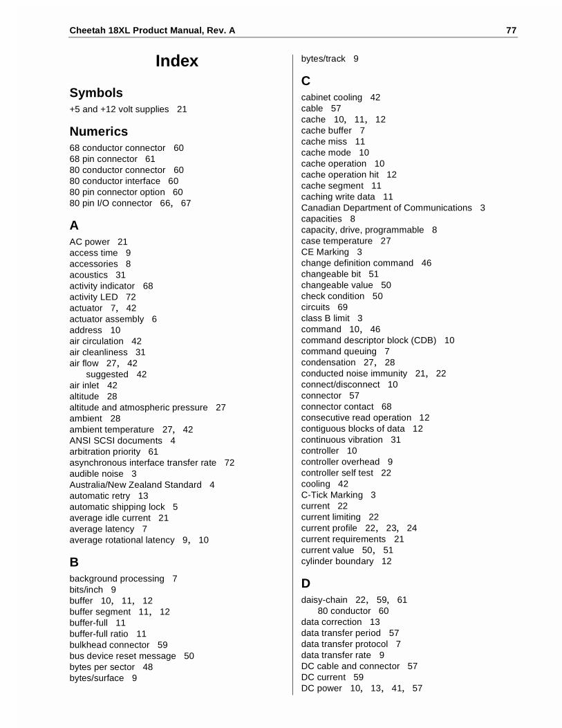
Cheetah 18XL Product Manual, Rev. A 77
Index
Symbols+5 and +12 volt supplies 21
Numerics68 conductor connector 6068 pin connector 6180 conductor connector 6080 conductor interface 6080 pin connector option 6080 pin I/O connector 66, 67
AAC power 21access time 9accessories 8acoustics 31activity indicator 68activity LED 72actuator 7, 42actuator assembly 6address 10air circulation 42air cleanliness 31air flow 27, 42
suggested 42air inlet 42altitude 28altitude and atmospheric pressure 27ambient 28ambient temperature 27, 42ANSI SCSI documents 4arbitration priority 61asynchronous interface transfer rate 72audible noise 3Australia/New Zealand Standard 4automatic retry 13automatic shipping lock 5average idle current 21average latency 7average rotational latency 9, 10
Bbackground processing 7bits/inch 9buffer 10, 11, 12buffer segment 11, 12buffer-full 11buffer-full ratio 11bulkhead connector 59bus device reset message 50bytes per sector 48bytes/surface 9
bytes/track 9
Ccabinet cooling 42cable 57cache 10, 11, 12cache buffer 7cache miss 11cache mode 10cache operation 10cache operation hit 12cache segment 11caching write data 11Canadian Department of Communications 3capacities 8capacity, drive, programmable 8case temperature 27CE Marking 3change definition command 46changeable bit 51changeable value 50check condition 50circuits 69class B limit 3command 10, 46command descriptor block (CDB) 10command queuing 7condensation 27, 28conducted noise immunity 21, 22connect/disconnect 10connector 57connector contact 68consecutive read operation 12contiguous blocks of data 12continuous vibration 31controller 10controller overhead 9controller self test 22cooling 42C-Tick Marking 3current 22current limiting 22current profile 22, 23, 24current requirements 21current value 50, 51cylinder boundary 12
Ddaisy-chain 22, 59, 61
80 conductor 60data correction 13data transfer period 57data transfer protocol 7data transfer rate 9DC cable and connector 57DC current 59DC power 10, 13, 41, 57
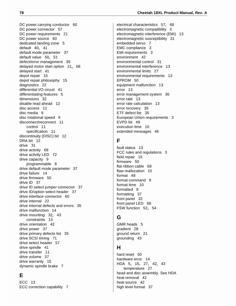
78 Cheetah 18XL Product Manual, Rev. A
DC power carrying conductor 60DC power connector 57DC power requirements 21DC power source 60dedicated landing zone 5default 40, 41default mode parameter 37default value 50, 51defect/error management 35delayed motor start option 21, 68delayed start 41depot repair 15depot repair philosophy 15diagnostics 22differential I/O circuit 41differentiating features 5dimensions 32disable read ahead 12disc access 11disc media 9disc rotational speed 9disconnect/reconnect 11
control 11specification 11
discontinuity (DISC) bit 12DRA bit 12drive 31drive activity 68drive activity LED 72drive capacity 9
programmable 8drive default mode parameter 37drive failure 14drive firmware 50drive ID 37drive ID select jumper connector 37drive ID/option select header 37drive interface connector 60drive internal 22drive internal defects and errors 35drive malfunction 14drive mounting 32, 43
constraints 13drive orientation 42drive power 37drive primary defects list 35drive SCSI timing 71drive select header 57drive spindle 41drive transfer 11drive volume 37drive warranty 15dynamic spindle brake 7
EECC 13ECC correction capability 7
electrical characteristics 57, 68electromagnetic compatibility 3electromagnetic interference (EMI) 13electromagnetic susceptibility 31embedded servo 7EMC compliance 3EMI requirements 3environment 42environmental control 31environmental interference 13environmental limits 27environmental requirements 13EPROM 50equipment malfunction 13error 13error management system 36error rate 13error rate calculation 13error recovery 35ETF defect list 35European Union requirements 3EVPD bit 49execution time 10extended messages 46
Ffault status 13FCC rules and regulations 3field repair 15firmware 50flat ribbon cable 68flaw reallocation 10format 48format command 9format time 10formatted 8formatting 37front panel 32front panel LED 68FSW function 52, 54
GGMR heads 5gradient 28ground return 21grounding 43
Hhard reset 50hardware error 14HDA 5, 15, 27, 42, 43
temperature 27head and disc assembly. See HDAheat removal 42heat source 42high level format 37
Cheetah 18XL Product Manual, Rev. A 79
host 12, 35, 41, 48, 59, 61host adapter 37
adapter/initiator 61host backplane wiring 59host equipment 43, 60
DC power 60host I/O signal 37host system 37host system malfunction 13host/drive operational interface 13hot plug 7, 15humidity 27, 28
II/O connector 59identified defect 35idle condition 25, 26Input characteristics 69inquiry command 49inquiry vital product data 49installation 37installation guide 4, 8installation instructions 37instantaneous current peak 21integrated Ultra1/Ultra2 SCSI controller 7interface cable length 61interface data 9interface requirements 45interface timing 13interleave 7internal data rate 9
JJ1-auxiliary 37jumper 8, 37, 40, 41, 68jumper function description 41jumper header 40jumper plug type 37
Llanding zone 7LB 11LED 72logical 10logical block 10, 11, 12logical characteristics 57logical segment (mode select page 08h) 10low level format 37low voltage differential (LVD) drivers and receivers 7LVD 68, 69LVD interface receiver circuits 69LVD output signals 69
Mmagnetoresistive heads 5mating connector 57, 60
mating flat cable connector 60maximum current requirements 22maximum operating current 21maximum starting current 21ME jumper 41mean time between failure. See MTBFmedia 7, 50media defect 13media defect induced error 13medium error 14message protocol 57message protocol system 36messages
SCSI interface 45miscellaneous features 56mode page 01 50mode page 08h 10mode parameter 50
page 08h 12mode select command 10, 11, 50mode select page 08h 12mode sense command 50, 51mode sense command page 08h 11mode sense data 50mode sense value 50model number table 5motor start command 10motor start delay option 68motor start option 10, 21, 68mounting configuration 32mounting configuration dimensions 32, 33mounting constraints 13, 43mounting point 43mounting surface 43mounting surface distortion 43mounting surface stiffness 43MTBF 13, 14, 27multimode drivers and receivers 7multiple segment 11multi-segmented cache control 10
Nnoise 22
audible 3non-operating 28, 29, 31
temperature 28non-operating vibration 31nonshielded 68 conductor connector 60
Ooffice environment 31operating 28, 29, 31operating environment 14operating option 37operating parameter 50operator intervention 13option jumper 37

80 Cheetah 18XL Product Manual, Rev. A
option jumper location 37option select header 57option select jumper 37options 8orientation 10, 29, 42out-of-plane deflection 43out-of-plane distortion 43Output characteristics 68
Ppackage size 29package test specification 4packaged 29parity 41parity checking 41parity error 41partition or logical drive 37PCB 15, 40, 42
temperature 27PCBA 37, 43, 50, 57, 59, 61PCBA circuit run 59PD jumper 41peak bits/inch 9peak starting current 21performance characteristics 9performance degradation 29peripheral I/O cable 22physical buffer space 10physical characteristics 57physical damage 31physical interface 57, 58physically contiguous blocks of data 12power 21, 22, 41power connector 21, 22power control switch 10power dissipation 25, 26power distribution 3power sequencing 22power supply voltage 13power-carrying conductor 60power-on 37, 68power-on operating hours 14power-on reset 50power-up 22, 41power-up hours 14prefetch 10, 11, 12prefetch (read look-ahead) 10, 12prefetch ceiling field 12prefetch data 12prefetch field 12prefetch hit 12prefetch mode 10prefetch of contiguous blocks 12prefetch operation 10, 12prefetch segmented cache control 10preventive maintenance 13, 15printed circuit board. See PCB
PRML read channel electronics 5product data page 49programmable drive capacity 8
Rradio interference regulations 3read 10read command 10, 11, 12read data 11read error 13read error rate 13, 35read operation 11read retry count 35read/write head 9ready 50receive diagnostic results 36receiver circuits 69recommended mounting 30recoverable seek error 13reference documents 4regulation 21relative humidity 28reliability 7reliability and service 14reliability specifications 13remote switch 37repair facility 15repair information 19REQ/ACK offset 57request sense command 36request sense information 14resonance 29retrieved data 11
SS.M.A.R.T. 7, 16safe power transmission 60safety 3Safety and Regulatory Agency Specifications 4, 8saved value 50, 51SCSI
commands 46format commands 13interface data transfer rate 9messages 45
SCSI bus cable 37SCSI bus condition 56SCSI bus ID 68SCSI bus phase sequence 56SCSI command 35SCSI I/O connector 58SCSI ID 37, 41SCSI interface 10, 13, 59SCSI interface cable 59SCSI interface commands supported 46SCSI interface connector 57SCSI interface data 9

Cheetah 18XL Product Manual, Rev. A 81
SCSI Interface Product Manual 1, 3, 4, 5SCSI systems error 36SCSI systems error consideration 35SCSI systems error management 36SCSI Ultra160 implementation 51SE 68Seagate support service 37sector 11sector interleave 9sector size 8sector sizes 10seek error 13seek positioning error 13segment 10, 11segment number 11self-contained 11Self-Monitoring Analysis and Reporting Technology.
See S.M.A.R.T.SE-LVD alternative 69sense key 14sequential read operations 12service
life 13, 15philosophy 15tools 15
servo data 5shielding 3shipping 19shipping container 28shock 29
and vibration 29shock mount 43signal ground 43single unit shipping pack 8single-ended (SE) drivers and receivers 7single-ended interface circuit 25, 26site installation 15software interleave 12spare part 15spindle 22spindle startup 41standard day 27standards 3start motor command 21start unit command 41start/stop time 10status 36stop spindle 10stop time 10storage capacity 35straight-in connector 61strict bit in Mode page 00h 11supply voltage 21support services 73synchronous data transfer 57synchronous data transfer operation 72synchronous data transfer period 57synchronous transfer period 72
system chassis 43system recovery procedures 13
Ttechnical support services 73temperature 10, 27, 42
ambient 27case 27gradient 27non-operating 28PCB and HDA 27regulation 3See also cooling
termination 22terminator enable jumper TE 61terminator power 70terminator requirements 37, 70TP1 position 41tracks/inch 9tracks/surface, total 9transfer period 57transmitter receiver circuits 69typical access time 10
UUltra160 mode 46Ultra160 SCSI 5Ultra160 SCSI controller 7Ultra160 SCSI interface 5, 7unformatted 8unrecoverable condition 13unrecoverable error 13unrecoverable seek error 14Unrecoverable write error 13
Vvibration 29, 31vital product data 49volatile memory 50voltage 10, 21
Wwarranty 7, 19wet bulb temperature 27wide Ultra160 SCSI interface 5WP jumper 41wrap-around 11write caching 11write error 13
unrecoverable 13write operation 11write protect 41write retry count 35

82 Cheetah 18XL Product Manual, Rev. A
Zzoned bit recording (ZBR) 7


Seagate Technology, Inc.920 Disc Drive, Scotts Valley, California 95066-4544, USAPublication Number: 75789506, Rev. A, Printed in USA