Embed Size (px)
Citation preview
Title 44pt Title Case
Affiliations 24pt sentence case
20pt sentence case
© ARM 2016
Safety and security for automotive SoC design
Chris Turner
Seoul, June 28th 2016
Director of advanced technology marketing, CPU group
Taipei, July 1st 2016

© ARM 2016 2
Title 40pt Title Case
Bullets 24pt sentence case
Sub-bullets 20pt sentence case
Emissions & efficiency
Advanced powertrain ECU
Electrification
Hybrid and all-electric
Infotainment
Smartphone connectivity
Connected car
Telematics, eCall, LTE, V2X
In-car networks
CAN, LIN, Ethernet
Reducing accidents
Passive and active safety
Smart cities
Intelligent traffic systems
Assisted driving
ADAS to highly assisted
Autonomous vehicles
Cloud services
Innovation in automotive computing
© ARM 2016 3
Title 40pt Title Case
Bullets 24pt sentence case
Sub-bullets 20pt sentence case
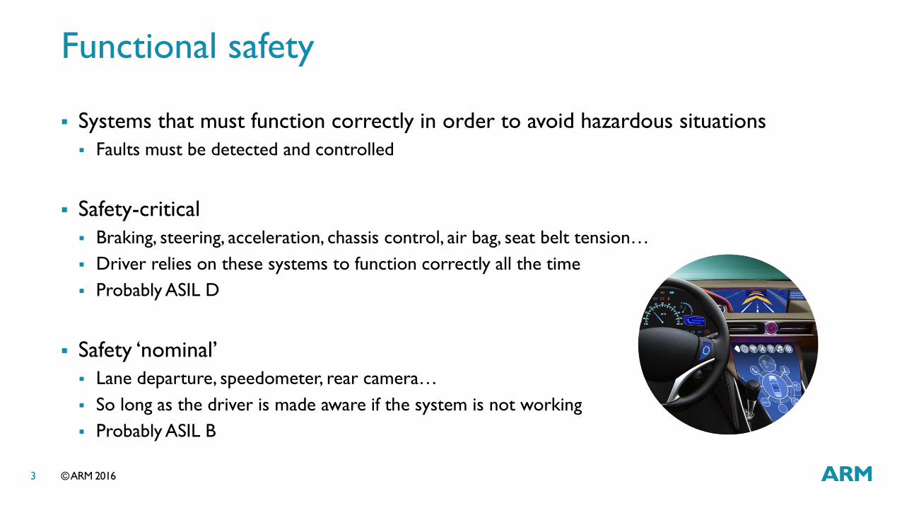
Functional safety
Systems that must function correctly in order to avoid hazardous situations
Faults must be detected and controlled
Safety-critical
Braking, steering, acceleration, chassis control, air bag, seat belt tension…
Driver relies on these systems to function correctly all the time
Probably ASIL D
Safety ‘nominal’
Lane departure, speedometer, rear camera…
So long as the driver is made aware if the system is not working
Probably ASIL B
© ARM 2016 4
Title 40pt Title Case
Bullets 24pt sentence case
Sub-bullets 20pt sentence case
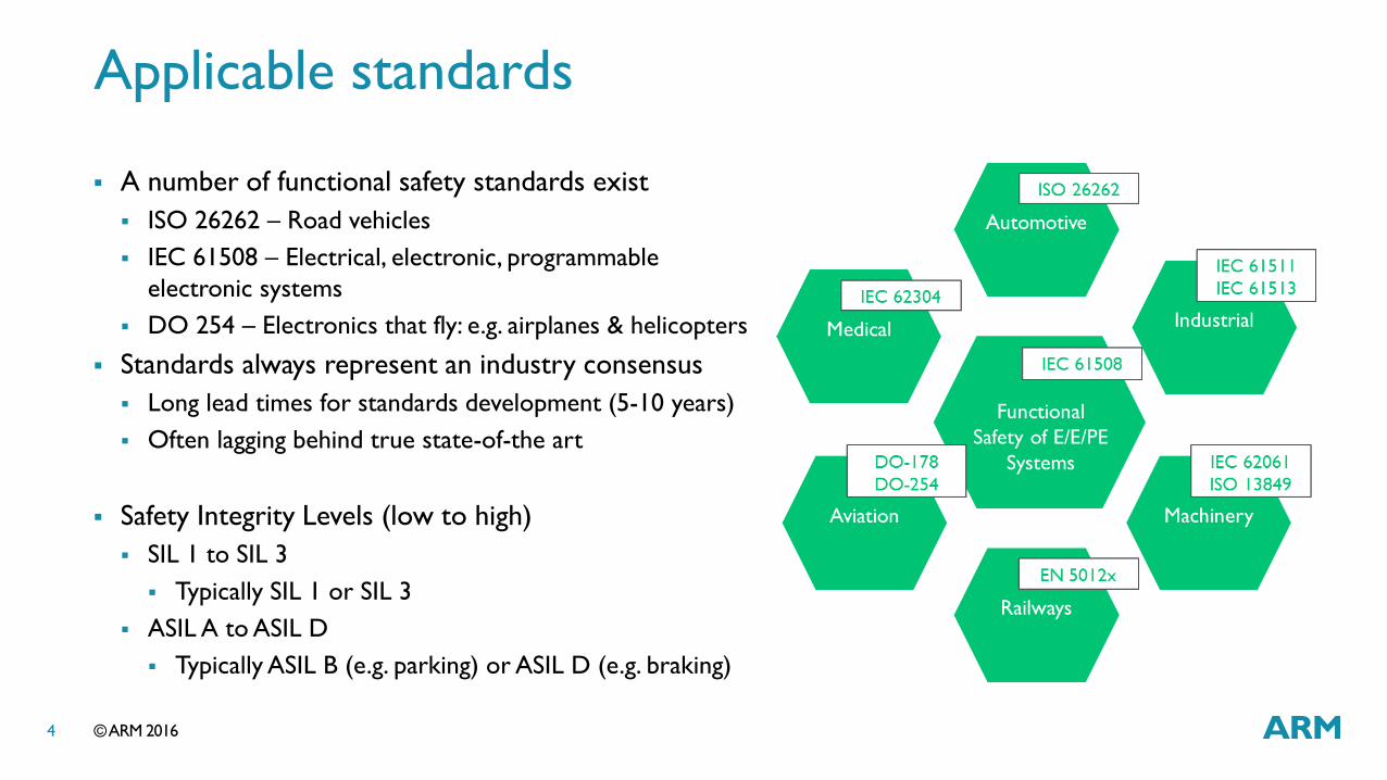
Applicable standards
A number of functional safety standards exist
ISO 26262 – Road vehicles
IEC 61508 – Electrical, electronic, programmable
electronic systems
DO 254 – Electronics that fly: e.g. airplanes & helicopters
Standards always represent an industry consensus
Long lead times for standards development (5-10 years)
Often lagging behind true state-of-the art
Safety Integrity Levels (low to high)
SIL 1 to SIL 3
Typically SIL 1 or SIL 3
ASIL A to ASIL D
Typically ASIL B (e.g. parking) or ASIL D (e.g. braking)
© ARM 2016 5
Title 40pt Title Case
Bullets 24pt sentence case
Sub-bullets 20pt sentence case
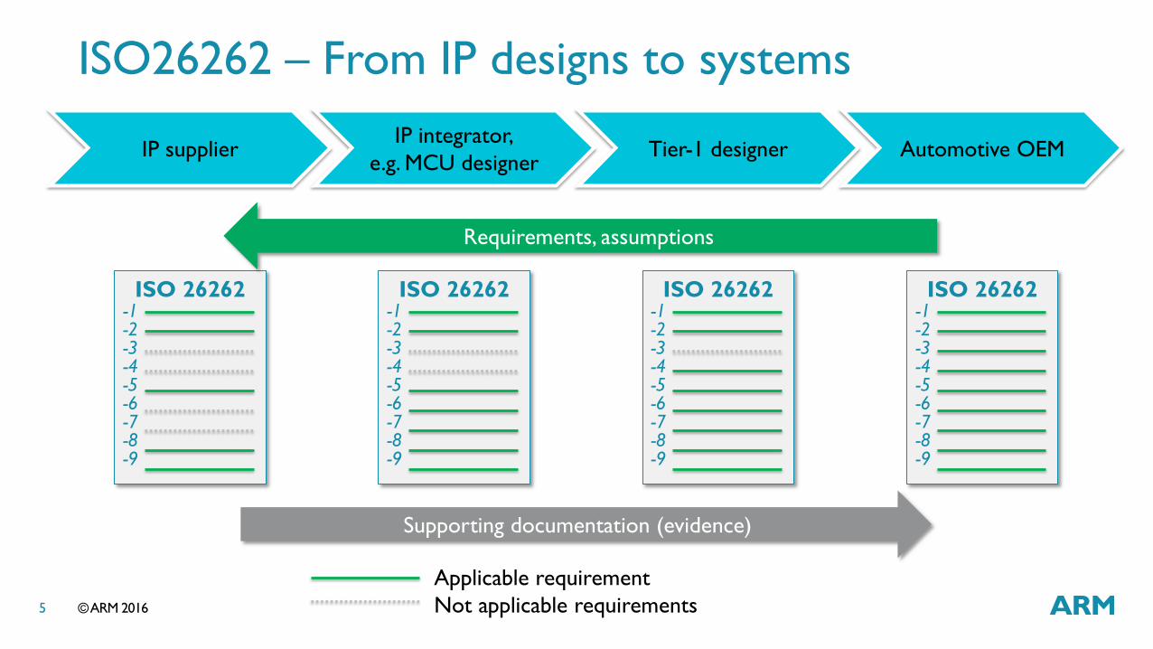
IP integrator,
e.g. MCU designer Tier-1 designer Automotive OEM IP supplier
ISO 26262 -1 -2 -3 -4 -5 -6 -7 -8 -9
ISO 26262 -1 -2 -3 -4 -5 -6 -7 -8 -9
ISO 26262 -1 -2 -3 -4 -5 -6 -7 -8 -9
Applicable requirement
Not applicable requirements
ISO 26262 -1 -2 -3 -4 -5 -6 -7 -8 -9
Requirements, assumptions
Supporting documentation (evidence)
ISO26262 – From IP designs to systems

© ARM 2016 6
Title 40pt Title Case
Bullets 24pt sentence case
Sub-bullets 20pt sentence case
Faults
Systematic faults
Hardware errata
Software bugs
Incorrect specification
Incomplete requirements
Random faults
Caused by hard errors, e.g. a failed
transistor or metal connection
Caused by soft errors, e.g. alpha particle
switches a RAM bit
Permanent faults that persist, or may be
recoverable if they’re managed
Transient faults that appear but may then go
away of their own accord. However, these
could cause a system to operate incorrectly
Latent faults that exist but do not impact
the system for some while, e.g. a RAM
error in a bit which isn’t accessed until
some time after it occurs
Source: ASML

© ARM 2016 7
Title 40pt Title Case
Bullets 24pt sentence case
Sub-bullets 20pt sentence case
Functional safety engineering
Random faults
Systematic faults HW and SW
Deployment
• QA
• Errata
Fault models
• Sources of errors
• Possible failures
• Fault detection design
• Fault control design • Error reporting
Process
• Requirements (traceable)
• Planning
• Training
• Design & Verification
• Tools
• Review & Assessment
• Audit
Fault metrics
• Permanent faults
• Transient faults
• FMEA
• SIL, e.g. for ASIL B or D • 90 or 99% SPFM
• 60 or 90% LFM
• Within FTTI
Design (HW and SW)
• LBIST and MBIST
• STL aka SWBIST
• ECC
• Exceptions
• Watchdogs
• DCLS
• Redundant execution
• Diversity
• Fail operational • At system level
• Fail silent at SoC level
Development
• Safety lifecycle
• Traceability • Project report
• Documentation • Safety manual
• AoU
• FMEA
• DIR
Audit & Assessment
• Internal and external
• A&A independence
• Level of detail • ASIL B
• ASIL D
Top-level requirements
• Hazards
• Risks
• Safety goal • Layered safety
requirements
• Required SIL/ASIL • Layered system
components
Considered for ASIL C and D.
Redundancy will be required

© ARM 2016 8
Title 40pt Title Case
Bullets 24pt sentence case
Sub-bullets 20pt sentence case
Automotive safety integrity levels
Fault metrics
Measurement of possible faults that are
detectable, and mitigated locally if possible
Single Point Fault Metric
Immediately effective faults
Latent Fault Metric
Initially silent faults, e.g. in memory bits
QM: Quality Managed
Safety SPFM LFM
QM Design assurance
ASIL A Nominal
ASIL B 90% 60%
ASIL C 97% 80%
ASIL D 99% 90%
Transient faults*
Permanent faults
* Expect to extend to ASIL B post 2018
© ARM 2016 9
Title 40pt Title Case
Bullets 24pt sentence case
Sub-bullets 20pt sentence case
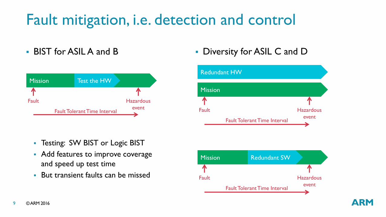
Fault mitigation, i.e. detection and control
BIST for ASIL A and B
Testing: SW BIST or Logic BIST
Add features to improve coverage
and speed up test time
But transient faults can be missed
Diversity for ASIL C and D
Mission
Fault
Hazardous
event
Fault Tolerant Time Interval
Test the HW
Mission
Fault
Hazardous
event
Fault Tolerant Time Interval
Redundant HW
Mission
Fault
Hazardous
event
Fault Tolerant Time Interval
Redundant SW
© ARM 2016 10
Title 40pt Title Case
Bullets 24pt sentence case
Sub-bullets 20pt sentence case
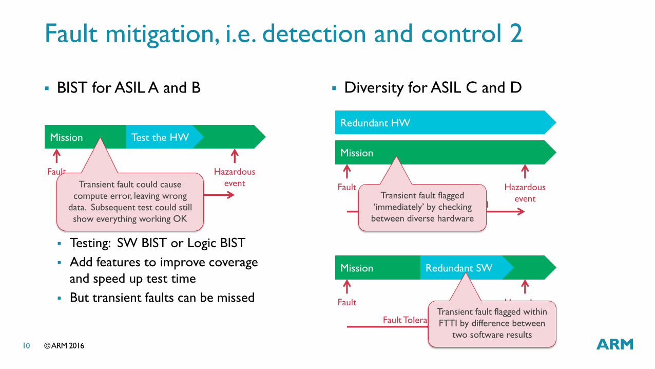
Fault mitigation, i.e. detection and control 2
BIST for ASIL A and B
Testing: SW BIST or Logic BIST
Add features to improve coverage
and speed up test time
But transient faults can be missed
Diversity for ASIL C and D
Mission
Fault
Hazardous
event
Fault Tolerant Time Interval
Test the HW
Mission
Fault
Hazardous
event
Fault Tolerant Time Interval
Redundant HW
Mission
Fault
Hazardous
event
Fault Tolerant Time Interval
Redundant SW
Transient fault could cause
compute error, leaving wrong
data. Subsequent test could still
show everything working OK
Transient fault flagged
‘immediately’ by checking
between diverse hardware
Transient fault flagged within
FTTI by difference between
two software results

© ARM 2016 11
Title 40pt Title Case
Bullets 24pt sentence case
Sub-bullets 20pt sentence case
Diverse systems
Dual or triple systems
Diverse implementations
Random and systematic
Can be fail-operational
Redundant hardware
Dual Core Lock Step, or
Dual asynchronous clusters
Memory ECC
Doubles/adds area & power
Need to test the checkers
Redundant execution
Temporal redundancy
Can halve performance
But 1:1 duty cycle may not
be needed
Separated safety island
required as a checker
Different solutions
A
B
C
+ AA SI +
A
A
© ARM 2016 12
Title 40pt Title Case
Bullets 24pt sentence case
Sub-bullets 20pt sentence case
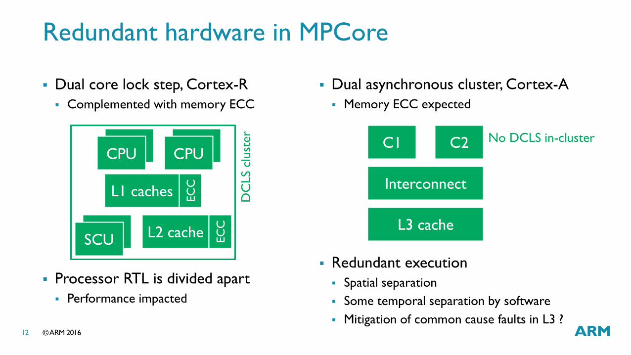
Redundant hardware in MPCore
Dual core lock step, Cortex-R
Complemented with memory ECC
Processor RTL is divided apart
Performance impacted
Dual asynchronous cluster, Cortex-A
Memory ECC expected
Redundant execution
Spatial separation
Some temporal separation by software
Mitigation of common cause faults in L3 ?
C1 C2
Interconnect
L3 cache
CPU CPU
L1 caches EC
C
CPU CPU
CPU SCU
L2 cache EC
C
DC
LS
clust
er No DCLS in-cluster
© ARM 2016 13
Title 40pt Title Case
Bullets 24pt sentence case
Sub-bullets 20pt sentence case
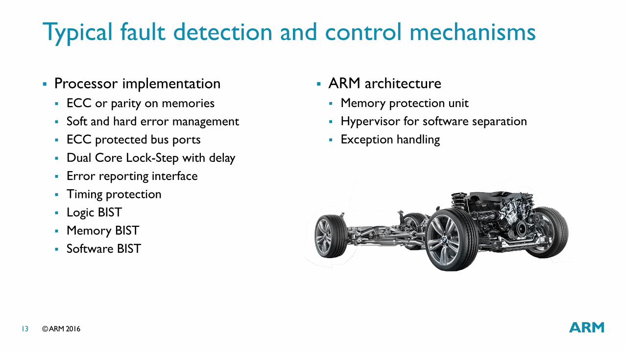
Typical fault detection and control mechanisms
Processor implementation
ECC or parity on memories
Soft and hard error management
ECC protected bus ports
Dual Core Lock-Step with delay
Error reporting interface
Timing protection
Logic BIST
Memory BIST
Software BIST
ARM architecture
Memory protection unit
Hypervisor for software separation
Exception handling
© ARM 2016 14
Title 40pt Title Case
Bullets 24pt sentence case
Sub-bullets 20pt sentence case
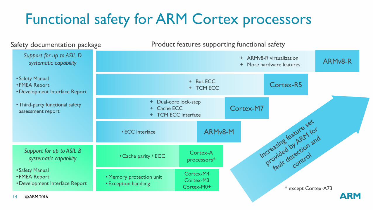
Functional safety for ARM Cortex processors
Support for up to ASIL D
systematic capability
Support for up to ASIL B
systematic capability
+ Bus ECC
+ TCM ECC Cortex-R5
+ ARMv8-R virtualization
+ More hardware features ARMv8-R
+ Dual-core lock-step
+ Cache ECC
+ TCM ECC interface Cortex-M7
•ECC interface ARMv8-M
Cortex-A
processors* •Cache parity / ECC
Cortex-M4
Cortex-M3
Cortex-M0+
•Memory protection unit
•Exception handling
• Safety Manual
• FMEA Report
•Development Interface Report
•Third-party functional safety
assessment report
Product features supporting functional safety Safety documentation package
• Safety Manual
• FMEA Report
•Development Interface Report * except Cortex-A73

© ARM 2016 15
Title 40pt Title Case
Bullets 24pt sentence case
Sub-bullets 20pt sentence case
Safety management
Requirements management
Quality
Errata management
Training
Documentation
Fault detection & control
Memory protection
Error correction
Redundancy
Error reporting
Fault containment
Fault injection
Safety Package contains
Safety Manual
Failure Modes Effects Analysis
Development Interface Report or
agreement
Silicon IP for functional safety
Design & Verification
ECC
generator
ECC
corrector
ECC
generator
Parity
generator
Parity
checker
Parity
generator
ECC
corrector
ECC
generator
ECC
corrector
Parity
checker
Parity
checker
Parity
checker
Inte
rco
nn
ect lo
gic
Co
rte
x-R
5 P
roce
sso
r
Pe
rip
he
rals
/Me
mo
ry
Da
ta (
an
d In
str
uctio
ns)
Ad
dre
ss &
Co
ntr
ol
ECC
Data
ECC
Data
Parity bit
Parity bit
Addr/Ctrl
Addr/Ctrl
Inputs Outputs
Fault
CPU
CP
U
copy
Delay
Delay
Delay
L1 memory
Delay
Checker
64-b
its
EC
C b
its
32
-bits
EC
C b
its
64-b
its
EC
C b
its
64-b
its
EC
C b
its
64-b
its
EC
C b
its
64-b
its
EC
C b
its
64-b
its
EC
C b
its
64-b
its
EC
C b
its
64-b
its
EC
C b
its
32
-bits
EC
C b
its
32
-bits
EC
C b
its
32
-bits
EC
C b
its
32
-bits
EC
C b
its
32
-bits
EC
C b
its
32
-bits
EC
C b
its
32
-bits
EC
C b
its
ECC
detect/
correct
ECC
detect/
correct
ECC
generate
RMW
if <32b
CPU
I
D
Processes Safety Package

© ARM 2016 16
Text 54pt sentence case

© ARM 2016 17
Title 40pt Title Case
Bullets 24pt sentence case
Sub-bullets 20pt sentence case
Functional safety package
Safety manual
Describes design and verification process
Fault detection & control features
Verification summary
FMEA report
Evidence of safety analysis on the ARM IP
Aids partners with their own SoC level FMEA
Development Interface Report
Defines interworking relationship with ARM
Replaces bespoke dev. interface agreement (DIA)
Other
Future products may have additional IP
E.g. Software test library
Safety Package contains
Safety Manual
Failure Modes Effects Analysis
Development Interface Report or
agreement
Safety Package
© ARM 2016 18
Title 40pt Title Case
Bullets 24pt sentence case
Sub-bullets 20pt sentence case
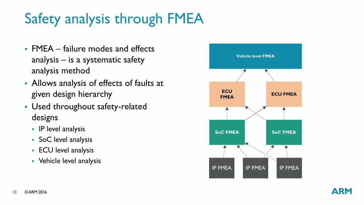
Safety analysis through FMEA
FMEA – failure modes and effects
analysis – is a systematic safety
analysis method
Allows analysis of effects of faults at
given design hierarchy
Used throughout safety-related
designs
IP level analysis
SoC level analysis
ECU level analysis
Vehicle level analysis
IP FMEA IP FMEA IP FMEA
SoC FMEA SoC FMEA
ECU
FMEAECU FMEA
Vehicle level FMEA

© ARM 2016 19
Title 40pt Title Case
Bullets 24pt sentence case
Sub-bullets 20pt sentence case
What’s in an FMEA?
Design is subdivided into smaller
elements
Number of hierarchy levels depends on
complexity of designs
Faults within each element, and
effects of faults locally and globally
are analysed
FMEA records are typically
presented in a tabular format
Instruction fetch unit (IFU)
Fault Error Failure
e.g. flipped bit in
program counter
e.g. incorrect program
counter value
e.g. incorrect
instruction execution
Example fault consideration within an element (IFU)
FMEA excerpt with potential effects
Failure mode
ID
Compone
nt levelBlock level
Safe
ty-r
ela
ted
Failure mode
description
Potential end
effect at CPU
boundary
FMEDA713 cortexa53 L1 duplicate tag
RAMs
Y Failure in reading from L1
duplicate tag RAMs
Performance
FMEDA710 cortexa53 L1 duplicate tag
RAMs
Y Failure in reading from L1
duplicate tag RAMs
Security Violation
FMEDA568 cortexa53 L1 duplicate tag
RAMs
Y Failure in reading from L1
duplicate tag RAMs
Livelock
FMEDA567 cortexa53 L1 duplicate tag
RAMs
Y Failure in reading from L1
duplicate tag RAMs
Modified Instruction
Execution
FMEDA543 cortexa53 L1 duplicate tag
RAMs
Y Failure in reading from L1
duplicate TAGS
Data corruption
Design hierarchy Failure mode information
© ARM 2016 20
Title 40pt Title Case
Bullets 24pt sentence case
Sub-bullets 20pt sentence case
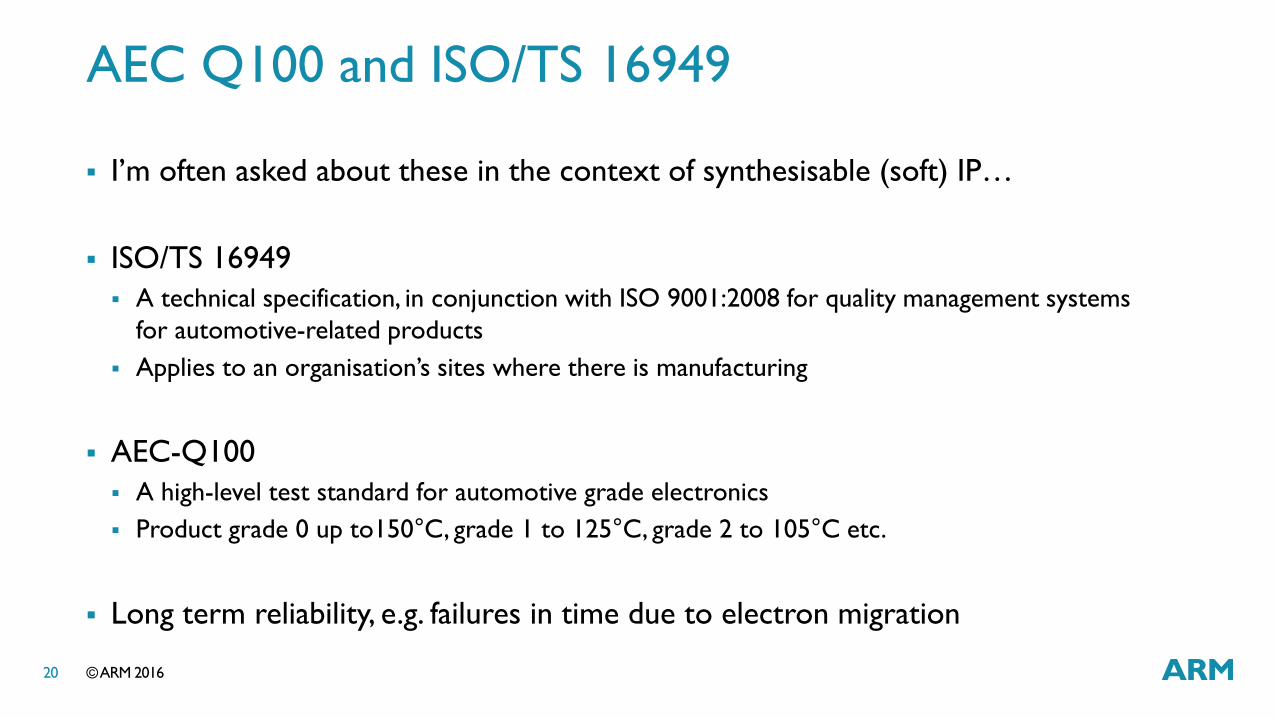
AEC Q100 and ISO/TS 16949
I’m often asked about these in the context of synthesisable (soft) IP…
ISO/TS 16949
A technical specification, in conjunction with ISO 9001:2008 for quality management systems
for automotive-related products
Applies to an organisation’s sites where there is manufacturing
AEC-Q100
A high-level test standard for automotive grade electronics
Product grade 0 up to150°C, grade 1 to 125°C, grade 2 to 105°C etc.
Long term reliability, e.g. failures in time due to electron migration

© ARM 2016 21
Title 40pt Title Case
Bullets 24pt sentence case
Sub-bullets 20pt sentence case
Automotive security threats
Theft
Intrusion
Privacy
Data protection
Location, speed, direction
Safety
Malicious hacking
Unauthorised upgrades

© ARM 2016 22
Title 40pt Title Case
Bullets 24pt sentence case
Sub-bullets 20pt sentence case
Safe systems must be secured
Cars offer multiple attack surfaces
From outside – wireless
From inside – On-board diagnostics port
Everything in a vehicle is connected
Conventional CAN and LIN bus
Real-time Ethernet
Debug, software provisioning and
updating has to be facilitated
Vehicle architectures are evolving to
include gateways with security
And protocol conversions
© ARM 2016 23
Title 40pt Title Case
Bullets 24pt sentence case
Sub-bullets 20pt sentence case
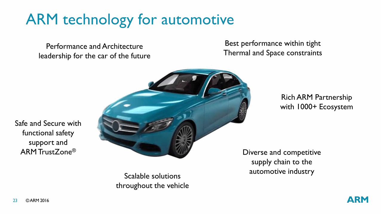
Rich ARM Partnership
with 1000+ Ecosystem
ARM technology for automotive
Diverse and competitive
supply chain to the
automotive industry
Performance and Architecture
leadership for the car of the future
Best performance within tight
Thermal and Space constraints
Safe and Secure with
functional safety
support and
ARM TrustZone®
Scalable solutions
throughout the vehicle

The trademarks featured in this presentation are registered and/or unregistered trademarks of ARM Limited
(or its subsidiaries) in the EU and/or elsewhere. All rights reserved. All other marks featured may be
trademarks of their respective owners.
Copyright © 2016 ARM Limited
© ARM 2016


![TRANSNET SOC LTD Tenders/GSM... · transnet soc ltd [registration no. 1990/000900/30] request for proposal [rfp] for the provision of an automotive port and rail supply chain study](https://img.pdfslide.us/doc/110x75/5b97727a09d3f2c05f8cbec9/transnet-soc-ltd-tendersgsm-transnet-soc-ltd-registration-no-199000090030.jpg)