Embed Size (px)
Citation preview

2006 Perimeter Rd. Greenville, SC 29605
Toll Free: 800-435-9340 - Phone: 864-277-5870
Fax: 864-235-9661 - www.mightymole.com
email: [email protected]
Safety and Operation Manual
Vacuum Systems
Table of Contents
Section
Forward................................................................................................ 1.0
Hazard Alert Decal............................................................................... 2.0
Hazard Alert Decal Placement............................................................. 3.0
Operation Controls and Placement...................................................... 4.0
Specifications and Maintenance........................................................... 5.0
Operation of Machine........................................................................... 6.0
Warranty and Return Policy.................................................................. 7.0
Maintenance Record............................................................................ 8.0
Manual Part No. 8040100C
© 2012 by McLaughlin Group, Inc. Revised 05.26.15
All rights reserved. No part of this manual may be reproduced in any form, or by any means
without prior written permission of McLaughlin Group, Inc.

FORWARD
This manual contains important safety information and op-
erational instructions for your McLaughlin system. Read
and understand this manual before operating this equip-
ment. Failure to do so may result in serious personal injury
or equipment damage.
Keep this manual with the equipment at all times for future
reference. If you sell this equipment, be sure to give this
manual to the new owner. A replacement copy of this
manual is available through your local McLaughlin dealer or
by contacting McLaughlin Group, Inc. directly at:
McLaughlin Group, Inc..
2006 Perimeter Road
Greenville, SC 29605
800-435-9340 toll free
864-277-5870 world wide
864-235-9661 fax
[email protected] email
www.mightymole.com
The illustrations, instructions and specifications in this
manual are subject to change. McLaughlin Group, Inc.
reserves the right to make product changes at any time.
Contact your McLaughlin Group, Inc. dealer for the latest
information on McLaughlin equipment.
1.0
MAINTENANCE
Weekly Maintenance:
Grease all grease points. (4way valve-cylinders point at rear of tank-boom
bearing
and all points on boom cylinders.
Check engine air filter.
Check air compressor air filter if equiped.
Check tires (air pressure and visual inspect for any gouges or cuts).
If equipped check boom pvc for deep gouges and cracks also check to
make sure packing glad is adjusted properly for full seal.
Check all safety shutdowns for proper operation (air compressor over
pressure and air oil temp).
Clean the water tank shutdown switch using low pressure water to prevent
float from sticking.
Check water tanks for any foreign debris such as sand or dirt. If present
suck the water tanks out with vacuum.
Clean boom out (spray water into the boom end hose while it is in vacuum
to wash any rocks or debris from the center section to prevent the pvc tube
from getting deep gouges or cracks in it).
Charge boom remote nightly if new style remote with charger supplied.
Wash out gate valve gates to prevent damage to the gate.
Never run hot box when traveling this can cause the flame
to go out and let fuel saturate the insulation when it
ignites this can cause the hot box to burn out.
If vacuum or pressure is ever in question for
preformance always zero gauge with engine off to check.
Full vacuum should be 14 to 16”HG and pressure should
be 4 to 6 PSI.
1.1
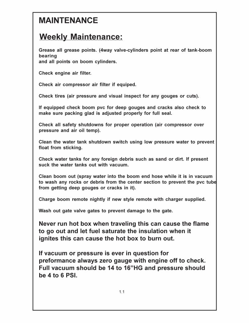
Standby water pressure should be 2900-3100PSI system.
The rotary lance should be 2700 to 3000 PSI (3000 PSI
MAX). The wand should be 1400 to 1600 PSI. If equipped
the potholing tool should be 1600 to 2000 PSI (2000 PSI
MAX).
Monthly Maintenance:
MAINTENANCE
Drain fuel water separator.
Inspect all suction hoses and air connection hoses for any signs of cracks.
Inspect door seal for splits or cuts.
1.2

2.0
BE AWARE OF SAFETY INFORMATION
This is the safety-alert sign. This symbol is
placed in the manual and on your machine to
alert you to potential bodily injury or death.
Hazard Alert Decals
SIGNAL WORDS
The safety-alert icon is used with the following
signal word: DANGER, WARNING, AND
CAUTION. When you see these words in the
manual or on decals on your machine, care
fully read and follow all instructions. Watch for
these words and learn their meanings.
DANGER Imminent hazard which, if not avoided,
will result in death or serious injury.
WARNING Potentially hazardous situation which,
if not avoided, could result in death
or serious injury.
CAUTION Potentially hazardous situation which,
if not avoided, may result in minor
personal injury or property damage.
READ YOUR OPERATOR’S MANUAL
Read and understand the operator’s manual
for your machine. Do not operate your machine
unless you have read and understand the
warnings and instructions contained in it.
Contact your McLaughlin dealer if your manual
becomes damaged or lost.
Keep hands, feet and clothing away from moving
parts.
Keep all shields and guards in place. Do not
modify or remove guards.
Turn off the machine before servicing.

2.1
Specific Hazard Alert Symbols
SERVICE AND MAINTENANCE
Make sure the machine is always in good
working condition. Safety devices must
always be installed and be funtioning property.
Check machine daily before operating.
Do not modify this machine. Use only
McLaughlin repair parts
Follow service and maintenance intervals.
PERSONAL PROTECTIVE EQUIPMENT
Proper protective equipment is required for safe
operation of this equipment.
Protective Equipment:
1. Hard hat 2. Safety Glasses/Shield
3. Safety Vest 4. Ear Protection
5. Electric Gloves 6. Electric Boots
Wear close fitting clothes.
Avoid jewelry such as bracelets, necklaces and
watches. Restrain long hair.
READ MANUAL
Carefully read and understand all safety
decals and proper operating techniques.
The safety decals in this manual contain
important information. Understanding
these decals will help you operate your
equipment properly. Replace missing or
damaged decals.
Allow only authorized personnel to operate
equipment. Closely supervise inexperienced
operators.

2.2
FLAMMABLE LIQUID
Fumes and/or fuel can explode or catch fire.
Shut off engine before refueling.
Keep engine and trailer free of fuel. Wipe up any
spilled fuel immediately.
HIGH PRESSURE AIR AND FLUIDS
This machine may use water, air, and hydraulic
fluid at high pressure.
Water from wand and air from lance can cause
serious injury. Wear protective clothing.
Relieve pressure before servicing.
MOVING PARTS
Keep hands, feet and clothing away from
moving parts.
Keep all shields and guards in place. Do
not modify or remove guards.
Turn off the machine before servicing.
LOCATE UNDERGROUND UTILITY LINES
Before starting work, make sure all underground
utilities have been properly located.
Inadvertent contact with buried utilities may cause
death or serious injury. Contact with electric lines
can cause electrocution. Contact with gas lines
can cause explosion or fire.

2.3
HOT FLUID UNDER PRESSURE
Hot fluid can burn or scald.
Wear protective clothing when servicing.
BATTERY ACID AND FLAMMABLE FUMES
The battery contains acid which can cause
severe burns. Avoid contact with eyes, skin
and clothing.
Fumes from the battery may explode. Keep
sparks and flame away from battery. Cables
and tools may cause sparks. Protect eyes
and face from battery.
CRUSHING WEIGHT
The spoil, tank, and door are very heavy. Stay
clear of the door when dumping the tank.
Trailer mounted systems may roll or tip if not
properly secured to the towing vehicle. The
following must be followed for operation,
dumping, and servicing the tank.
1. The trailer tongue must be properly
attached to the towing vehicle.
2. The towing vehicle’s tires must be
chocked.
3. The towing vehicle’s parking brake
must be applied.
Skid mounted units must be properly secured to
transporting vehicle or system before operating
or servicing. Transporting vehicle must have
wheels chocked and parking brake applied during
operation and servicing.

2.4
This machine produces a high volume of air flow.
Direct contact of the mouth and/or nose to the
vacuum air flow can result in death by suffocation.
Do not allow hoses or tools to come in contact with
skin, hair and clothing.
Never put the suction end of a tool or hose near
your face. The vacuum can collapse your lungs.
Never use this machine in a manner that is
inconsistent with its intended design.
SUFFOCATION HAZARD
FLYING OBJECT HAZARDThis machine uses either water or air under pressure.
The ground engaging tools can cause objects to
become airborne.
Flying objects can cause injury or property damage.
Keep all nonessential people away from the work
area.
TRANSPORTING MACHINE Make sure all components are stored properly.
Turn off the engine and relieve water system pressure.
Trailer units should be verified for the following:
1) The hitch, safety chains, and trailer wiring is properly connected.
2) The jack is in its fully retracted position.
Close all valves and doors.
Remove wheel chocks.
REMEMBER: A fully loaded or partially loaded unit will pull differently
than when it is empty. A loaded unit requires longer stopping distances.
Also, liquid tend to “slosh” when stop.
Make sure that the tires are inflated properly and that the brakes work
properly.

3.0
WARNING: FAILURE TO FOLLOW ANY OR ALL OF THE SAFETY
INSTRUCTIONS IN THIS MANUAL, COULD RESULT IN DEATH OR
SERIOUS INJURY. DO NOT USE THIS MACHINE IN A MANNER
THAT IS INCONSISTENT WITH ITS INTENDED DESIGN.
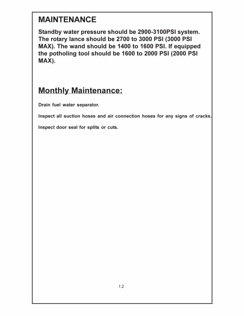
Hazard Alert Decal PlacementHAZARD ALERT DECAL MAINTENANCE
Hazard alert decals on your machine contain important information that will help
you operate your equipment safely.
Decals maintenance:
1. Keep decals clean. Clean with soap and water. Do not use harsh chemicals, or
spray decals directly with a high pressure washer.
2. Replace decals when they become damaged or hard to read. Clean the surface
of dirt, grease and oil before applying.
3. When replacing a mabhine component with a decal on it, replace the decal also.
4. See your local dealer or contact McLaughlin for replacement decals.
5. Replacement part number appears on each decal, as well as in this manual.
3.1
DIESEL POWER PACKS - SKID ONLY
DIESEL POWER PACKS - CURB SIDE
Read Manual.
Death or serious injury may result.
Read and understand
all safety and operating instructions.
BEFORE operating any equipment.
W A R N I N G
J200420
Decal: J200420
Moving parts.
Death or serious injury
may result.
Stop engine
before servicing.
J200425
Decal: J200425
WARNING
McLAUGHLIN GROUP, INC.2006 PERIMETER RD GREENVILLE, SC 29605
PR
OP
RIE
TA
RY
IN
FO
RM
AT
ION
TH
IS D
RA
WIN
G IS
TH
E P
RO
PE
RT
Y O
FM
cL
AU
GH
LIN
. A
LL
IN
FO
RM
AT
ION
C
ON
TA
INE
D H
ER
EIN
IS
C
ON
FID
EN
TIA
L A
ND
PR
OP
RIE
TA
RY
.
IT IS
NO
T T
O B
E U
SE
D,
RE
PR
OD
UC
ED
, C
OP
IED
OR
SH
OW
N
TO
AN
Y T
HIR
D P
AR
TY
WIT
HO
UT
W
RIT
TE
N C
ON
SE
NT
FR
OM
M
cL
AU
GH
LIN
.
PART NUMBER MATERIAL
TITLE
EST. WT.
DRAWN BY
DATE DRAWN
MACHINE REF
NEXT ASSEMBLY
HEAT TREAT
DO NOT SCALEDRAWING
# PERMACHINE
PAINT
PR
IME
UNLESS NOTED:
ALL DIMENSIONS IN INCHES
BREAK ALL SHARP EDGES
FINISH ALLMACHINED SURFACES
64
FRACTIONAL :
STANDARD TOLERANCES
X.XX :
X.XXX :
ANGULAR : J200032
DECAL REMOTE OIL DRAIN PANEL ISO
B
ENGINEER
SCALE
RELEASE DATE
SHEET
1 OF 1
1
SD
6-6-08
6-6-08
-
ENGR FILES/DECALS
SKID ONLYUNITS
-
MATERIAL NOTE:1. Material to be GE .010 Velvet Matte Lexan polycarbonate film.2. 3M 9672 Adhesive, 5 mil thick.3. Subsurface screened with Techmark, MTS UV, or equivalent.4. UV inhibitor additive: TINUVIN 1130 or equivalent.5. Split backing paper.6. Colors are Safety White, Safety Black and Safety Blue per Z535.1.
8 7/16
1 1
/2
R1/16
DECAL PART NO.PRINTED ONLOWER RIGHTCORNER
REVISION HISTORYREV DESCRIPTION DATE APPR
1 CHANGED MAT'L & ARTWORK 8-26-09 SD
1
1REMOTE OIL DRAIN PORTS
BLOWER OIL
SIDE 1
WATER PUMP
OIL
BLOWER OIL
SIDE 2
ENGINE
OIL
ENGINE
COOLANT

3.2
DIESEL POWER PACKS - CURB SIDE
UNITS WITH
MANUAL
LOCKING DOOR
1. Open gate valve - drain liquid - close gate valve
2. Remove inlet port plug
3. Click FULL TANK OVERRIDE switch to ON position - Start engine
4. Install inlet port plug to build vacuum
5. Unlock tank door
6. DO NOT STAND AT REAR OF UNIT - shut off engine
7. Wait for vacuum to release the door - start engine
8. Hold TANK RAISE switch up to raise tank
9. After dumping, hold TANK LOWER switch down to lower tank
10. Lock tank door
INSTRUCTIONS
J200466
DUMP PROCEDURE MANUAL DOOR
Decal: J200466
UNITS WITH
MANUAL
LOCKING DOOR
1. Open gate valve on tank inlet - tank will not build vacuum
2. Click FULL TANK OVERRIDE switch to ON position
3. Start engine
4. Hold TANK RAISE switch up to open door and raise tank
5. After dumping, hold TANK LOWER switch down to lower tank
and close door
6. Shut off engine J200481
Decal: J200481
DUMP PROCEDURE HYDRAULIC DOOR
INSTRUCTIONS

DIESEL POWER PACKS - CURB SIDE CONT’D
OPERATION
SAFETY MANUAL
Decal: J200465
AND
Rotating pulleys
and belts.
Do not operate
without guards
in place.J200445
Decal: J200445
WARNING
Decal: J200400
Crushing weight.
Rolling or tilting trailer will cause death
or serious injury.
Chock tires and apply parking brake
before operating or servicing.
Do not operate
unless attached to the towing vehicle.
D A N G E R
J200400
WARNING
Locate Utilities
Call 888-258-0808
Decal: J000210
Electricity, or Gas
Explosion Can Kill
c2004 Hazard Communication System, LLC 800-748-0241 www.safetylabel.com 04134 Reorder No. J200468
Decal: J200468
INSTRUCTIONSSTART PROCEDURE
1. Fill water tank
2. Open ball valve-prime water pump
3. Remove port plug from inlet port
4. Preheat engine - (cold start) 15 seconds
5. Depress murphy switch - start engine
6. When light goes out release murphy switch
3.3

DIESEL POWER PACKS - STREET SIDE
BATTERIES
Rotating pulleys
and belts.
Do not operate
without guards
in place.J200445
Decal: J200445
WARNING
Flammable fumes. Fumes may explode or catch.
Keep away from sparks and open flame.
Decal: J200430
Protect face, hands and body when servicing.
W A R N I N G
J200430INSIDE DIESEL
ENCLOSURE
VSK100GVT750G
Moving parts.
Death or serious injury
may result.
Stop engine
before servicing.
Decal: J200425
WARNING
Battery acid.
Battery acid can burn skin and eyes.
3.4
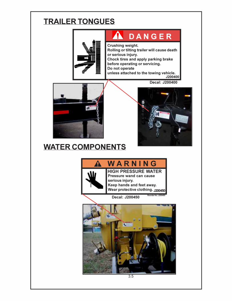
TRAILER TONGUES
WATER COMPONENTS
Reorder No. J200450
W A R N I N GHIGH PRESSURE WATERPressure wand can cause
serious injury.
Keep hands and feet away.
Wear protective clothing. J200450
Decal: J200450
Crushing weight.
Rolling or tilting trailer will cause death
or serious injury.
Chock tires and apply parking brake
before operating or servicing.
Do not operate
unless attached to the towing vehicle.
D A N G E R
J200400
Decal: J200400
3.5

RADIATORS
FUEL TANKS
DIESEL UNITS
VSK100G/D
VT750G
WARNING
Flammable liquid.
Fuel and fumes can
explode or catch fire.
Turn engine off.
BEFORE fueling.
Wipe up spilled fuel
immediately.
Decal: J200440
J200440
Hot fluid
under pressure.Hot coolant and steam
can burn or scald.
NEVER open when hot.
WARNING
J200435
Decal: J200435
3.6
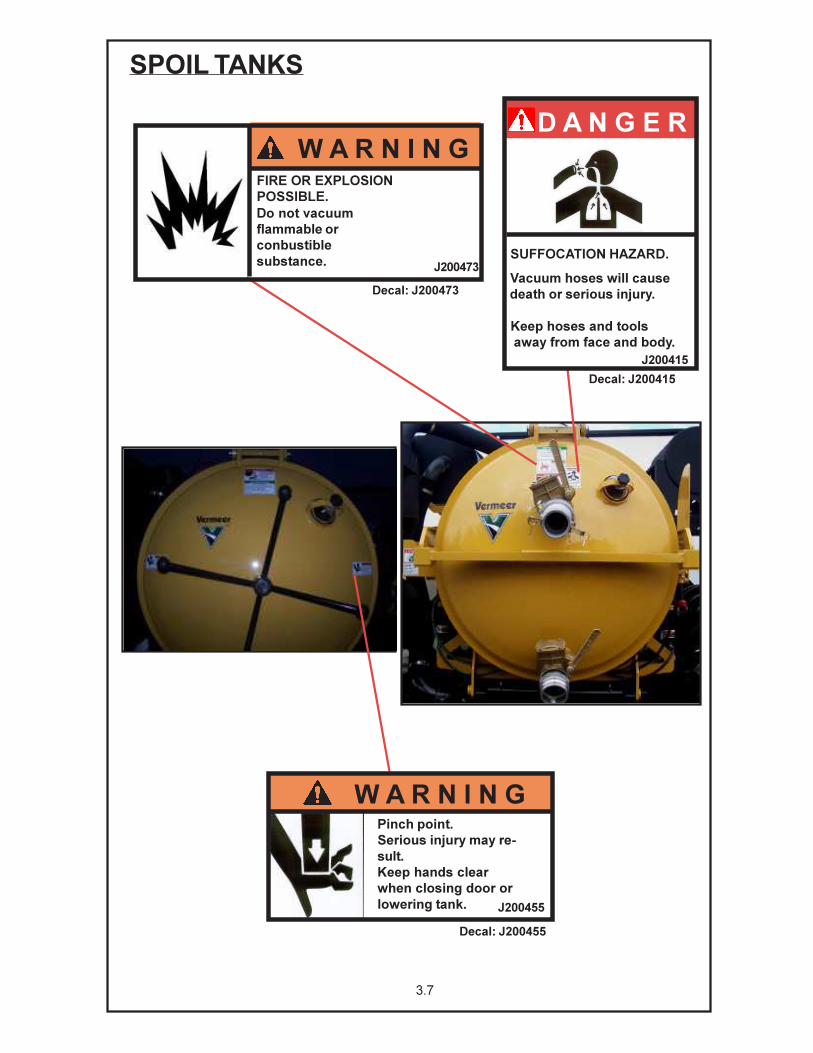
3.7
Pinch point.
Serious injury may re-
sult.
Keep hands clear
when closing door or
lowering tank. J200455
Decal: J200455
W A R N I N G
FIRE OR EXPLOSION
POSSIBLE.
Do not vacuum
flammable or
conbustible
substance. J200473
Decal: J200473
W A R N I N G
SPOIL TANKS
J200415
SUFFOCATION HAZARD.
Vacuum hoses will cause
death or serious injury.
Keep hoses and tools
away from face and body.
Decal: J200415
D A N G E R

SPOIL TANKS (CONT.)
Crushing weight.
Decal: J200410
D A N G E R
Spoil and door will cause death
or serious injury.
Unlock door only under
vacuum.
Stay away from door
when dumping.J200410
UNITS WITH
MANUAL
LOCKING DOOR
1. Open gate valve - drain liquid - close gate valve
2. Remove inlet port plug
3. Click FULL TANK OVERRIDE switch to ON position - Start engine
4. Install inlet port plug to build vacuum
5. Unlock tank door
6. DO NOT STAND AT REAR OF UNIT - shut off engine
7. Wait for vacuum to release the door - start engine
8. Hold TANK RAISE switch up to raise tank
9. After dumping, hold TANK LOWER switch down to lower tank
10. Lock tank door
INSTRUCTIONS
Decal: J200466
J200466
DUMP PROCEDURE MANUAL DOOR
3.8

SPOIL TANKS (CONT.)
W A R N I N GCRUSHING WEIGHT
DEATH OR SERIOUS INJURY COULD
RESULT
EMPTY TANK BEFORE SERVICING
ALWAYS INSTALL SAFETY BAR
WHEN WORKING ON RAISED TANK
J200458
Decal: J200458
Decal: J200455
Pinch point.
Serious injury may
result.
Keep hands clear
when closing door or
lowering tank.
W A R N I N G
J200455
3.9

GAS ENGINES AND GUARDS
Decal: J200400
Crushing weight.
Rolling or tilting trailer will cause death
or serious injury.
Chock tires and apply parking brake
before operating or servicing.
Do not operate
unless attached to the towing vehicle.
D A N G E R
J200400
OPERATION
AND
SAFETY MANUAL
Decal: J200465
Locate Utilities
Call 888-258-0808
Decal: J000210
WARNING
Electricity, or Gas
Explosion Can Kill
VSK100G
ALL GAS UNITS
Rotating pulleys
and belts.
Do not operate
without guards
in place.J200445
Decal: J200445
WARNING
3.10

BOOM
ELECTROCUTION HAZARD
DANGER
J200403
Death or serious injury will result if boom
approaches or touches overhead
electric power lines.
Keep boom away from overhead utilities.
Use caution when operating boom.
Decal: J200403
Decal: J200411
3.11

TOOLS
SUFFOCATION HAZARD.
Vacuum hoses will cause
death or serious injury.
Keep hoses and tools away
from face and body.
J200415
Decal: J200415
DANGER
HIGH PRESSURE WATER
Pressure wand can cause
serious injury.
Keep hands and feet away.
Wear protective clothing.
J200450
Decal: J200450
W A R N I N G
Reorder No. J200450
3.12

4.0
DIESEL CONTROLS
6. Full Tank Override Indicator
11. Fuel Gauge
2. Oil Pressure Indicator
1. Coolant Temperture Indicator
3. Battery Indicator
4. Full Tank Indicator
5. Low Water Indicator
7. Emergency Stop
8. Full Tank Override Switch
12. Hour Meter
14. Throttle Switch
9. Antifreeze Switch10. Tank Raise/Tank Lower
13. Ignition Switch
15. Automatic Throttle
16. Water Pump Switch17. Worklight Switch18. Hydraulic Jack Switch
19. Compressor Switch
20. Aux. Hydraulic Switch
a. Engine Will Run While Tank Is Full
b. Engine Will Shut Off When Tank Is Full
a. High Throttle
b. Low Throttle
a.
b.c.
d.
a.b.
Preheat
Off
Run
Start
Water Pump On/Compressor Off
Compressor On/Water Pump Off
a
b
1920
9
1
2
3
4
5
10
11
14
13
12
15
16
17
18
8
7
6
a
b
a b c
d
a
b

VT750G (Control Decal Sheet Part #J200056)
GAS CONTROL
2
3
5
1
1. Throttle Control Down Position Runs engine at idle.
Up Position Runs engine at full throttle.
2. Ignition Switch First Stop Turns on electrical system.
Clockwise Second Stop Starts engine.
3. Toggle Switch Override Bypasses the the level float switch
To Dump in the spoil tank that normally shuts
Full Tank the engine down when the spoil tank
is full.
4. Toggle Switch Water Pump Turns water pump on and off.
5. Toggle Switch Up Position Raises Tank
Down Position Lowers Tank
1
23 4
VSK100G (Control Decal Sheet Part #8040427)
4.1

BOOM CONTROLS
4.2
MANUAL ROTATION
WITH REVERSE FLOW BOOM
TRANSMITTER
1 2 3
4 5 6
Manual Rotation With Reverse Flow(Overlay Part: 8043075)
- BOOM RAISE
- BOOM LOWER
- BOOM EXTEND
- BOOM RETRACT
- BOOM BREAK
- GATE VALVE
HYDRAULIC ROTATION
WITH REVERSE FLOW BOOM
TRANSMITTER
1 2 3
4 5 6
7 8
Hydraulic Rotation With Reverse Flow(Overlay Part: 8041923)
- BOOM RAISE
- BOOM EXTEND
- BOOM LOWER
- BOOM RETRACT
- GATE VALVE
- BOOM ROTATION (CW)
- BOOM ROTATION (CCW)
MANUAL AND HYDRAULIC
ROTATION WITHOUT
REVERSE FLOW BOOM
TRANSMITTER
1 2 3
4 5 6
Manual Rotation Without Reverse Flow (Overlay Part: 8041922)
- BOOM RETRACT
- BOOM ROTATION (CCW)
- BOOM ROTATION (CW)
- BOOM EXTEND
- BOOM RAISE
- BOOM LOWER
POWER
BATTERY POWER
LEVEL
SIGNAL STRENGTH
BOOM RAISE
BOOM EXTEND
BRAKE
BOOM LOWER
BOOM RETURN
GATE VALVE
MANUAL ROTATION
WITH REVERSE FLOW
BOOM TRANSMITTER
Open/CloseOn/Off
1
1. Throttle Control Down Position Runs engine at idle.
Up Position Runs engine at full throttle.
2. Ignition Switch First Stop Turns on electrical system.
Clockwise Second Stop Starts engine.
3. Toggle Switch Override Bypasses the the level float switch
To Dump in the spoil tank that normally shuts
Full Tank the engine down when the spoil tank
is full.
4. Toggle Switch Water Pump Turns water pump on and off.
5. Toggle Switch Up Position Raises Tank
Down Position Lowers Tank
4

5.0
VACUUM TANK DOOR
DANGER: CRUSHING WEIGHT. SPOIL AND DOOR WILL CAUSE DEATH OR SERIOUS
INJURY. UNLOCK DOOR ONLY UNDER VACUUM. STAY AWAY FROM DOOR WHEN
DUMPING.
Door Handle
The vacuum tank door should only be unlocked under full vacuum. The area
behind the unit must be clear of all personnel before opening the door.
To Open The Door:
1. Remove the plug from the inlet port.
2. Start the engine and operate at low speed.
3. Insert the inlet port plug back into inlet port.
4. A minumum of 5” Hg vacuum must be achieved.
5. Turn the door handle counterclockwise until it
unscrews.
6. Turn off the engine and remain at the control panel
until the vacuum releases the door.
7. With the area behind and around the door clear of
personnel, the tank may be raised.
WATER SYSTEM
Water Tank Ball Valve and In-Line Strainer
The Water Tank Ball Valve is located on the bottom of the
tank, on the operator’s side.
1. On Turn handle in line with the valve.
2. Off Turn handle perpendicular to the valve.
The ball valve on the water tank must always be open
when the water pump is drawing water from the tank.
Operating the water pump with the ball valve closed will
result in damage to the water pump. Close the ball valve
to clean the strainer or service the water system without
draining the tank.
The in-line strainer protects the water pump from particles
that may cause damage. A drain plug is located at the
bottom of the strainer which may be used to drain the
entire system. The strainer should be periodically
checked for debris and cleaned.
DrainIn-Line Strainer
Drain
In-Line Strainer

Control Valves
5.1
WATER SYSTEM
Antifreeze and Valve
The antifreeze tank is plumbed into the water pump inlet.
The antifreeze tank ball valve is located directly beneath
the tank. The valve should remain closed during the
antifreeze procedure. Always verify the antifreeze tank is
not empty and the water tank ball valve is closed before
opening the antifreeze ball valve.Ball Valve
Antifreeze Tank
The Control Valves are located on each water
hose
reel and beside the tank. The valve beside the
tank
controls the in-tank cleanout.
1. On Turn handle in line with the body.
2. Off Turn handle perpendicular to body.
Tools may be changed while the engine is running
by
closing the hose reel valve and relieving the tool
pressure.
Use this valve to relieve system pressure in the
water
hose.
NOTE: To relieve system pressure, tool must be
disconnected from hose.
WATER SYSTEM
Tank Cleanout Valve
Hose Reel Valve
WATER SYSTEM
Water Assisted Tools
Water Assisted Tools have the water control on the tool.
Atigger lever controls the water flow.
1. On Squeeze the trigger lever.
2. Off Release the trigger lever.
Changing tool in operation:
1. Turn off the water pump clutch at the control panel.
2. Squeeze the trigger lever to relieve pressure in the hose.
3. Disconnect the Water Supply Hose and change tools.
4. Turn on the water pump clutch at the control panel.
Trigger Lever

Options
ARROW BOARD
ARROWBOARD SWITCH
Arrow Board
The Arrow Board is located at the back, on the top
of the Spoil Tank. It signals directions to on coming
traffic to go around machine whie working.
Jetter
WATER PUMP ON/OFF
HOSE RETRACT
The Jetter Reel is located on the side of the
trailer skid. The Jetter Reel is used to supply
water hose to jet out sewer lines. The jetter
Pendant contains the water pump on/off switch
and hose retract switch.
JETTER VALVEJETTER PENDANT
JETTER NOZZLE
5.2
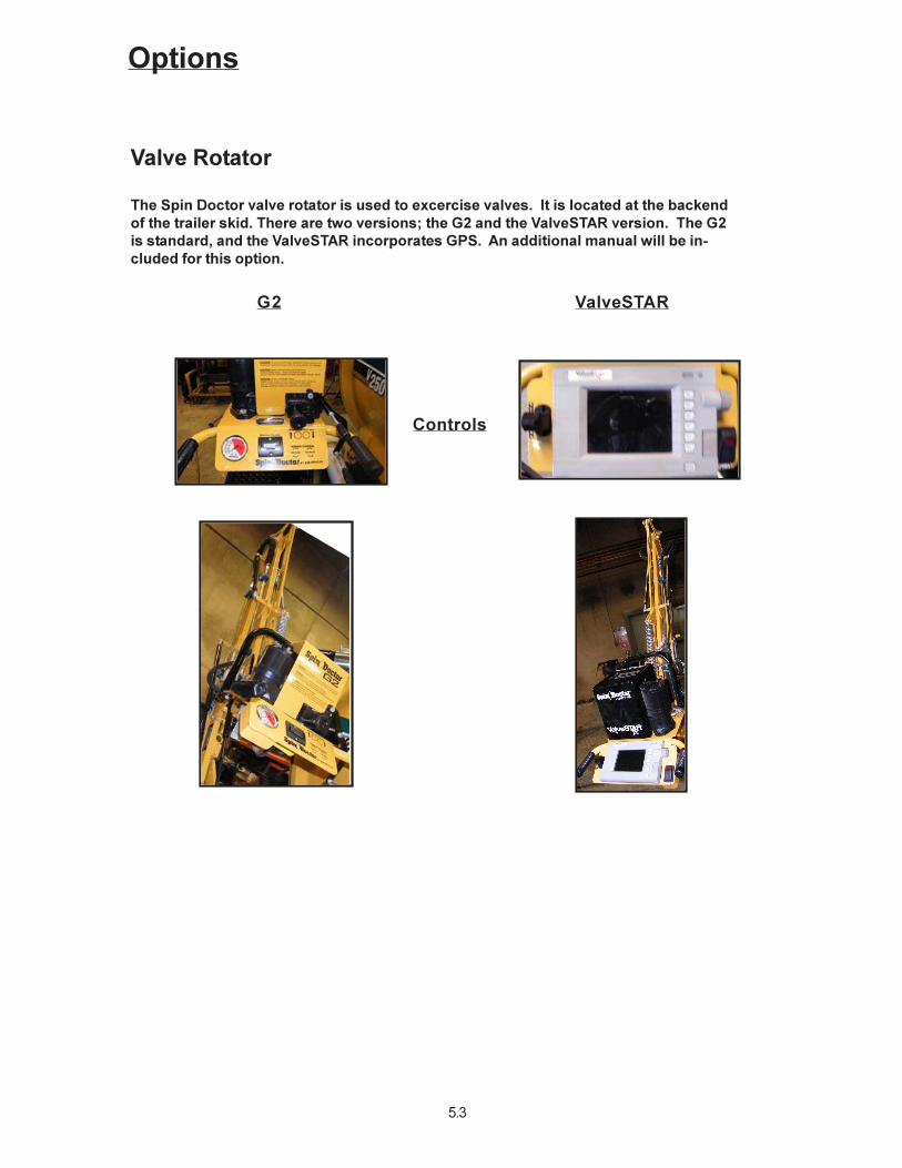
Options
Controls
ValveSTARG2
The Spin Doctor valve rotator is used to excercise valves. It is located at the backend
of the trailer skid. There are two versions; the G2 and the ValveSTAR version. The G2
is standard, and the ValveSTAR incorporates GPS. An additional manual will be in-
cluded for this option.
Valve Rotator
5.3

Options
REV. FLOW HANDLE
Reverse Flow
Pressure Pushes air out of the tank
ports and boom if
supplied.
Neutral Air Circulates inside the
blower. Use this position
to start the engine.
Vacuum Pulls air into the tank.
Hot Box
The Hot Box is located on side of the trailer skid.
The Hot Box is used to heat the water used by
the machine.
HOT BOX
HOT BOX CONTROL
Emergency Manual Override Boom Operation
The intent of the manual override switches is to provide
a means to operate the boom to get it into the storage
cradle in the occurrance that the transmitter has become
damaged or lost. EXTEND BRAKE
LOWER RETRACT
RAISE
5.4

Options: Aux. Hydraulic
HYDRAULIC TANK
Auxillary Hydraulics
Auxillary hydraulics allow for the connection
of hydraulic tools and the rotation of a hy-
draulic boom. The controls are located
below the engine control panel. The hose
connections are also located at the controls.
CONTROLS
HYDRAULIC JACK
Hydraulic Jack
The Hydraulic Jack is located at the front of the
trailer. The Hydraulic Jack is used to automaticlly
raise/ lower trailer tongue.
5.5

5.6
MAINTENANCE
GAS ENGINE (Per Specs in Honda GX670 Operator’s Manual)
Engine Oil Specs:
SAE 10W-30, API SJ
Above 50°F (10°C) SAE 30 or SAE 10W-30
0°-50°F (0°-18°C) SAE 5W-30 / 10W-30
Below 0°F (-18°C) SAE 5W-30
Service Intervals: Refer to engine Operator’s Manual for complete Service Schedule.
- Change engine oil: First 20 hrs., every 100 hrs.
- Change oil filter: Every 200 hrs.
- Clean air filter: Every 50 hrs.
- Change air filter: Every 200 hrs.
- Change fuel filter cartridge: Every 200 hrs.
DIESEL ENGINE (Per Specs in Kubota Operator’s Manual)
Engine Oil Specs:
Should be MIL-L-2104C or have properties of API classification CD/CE grades.
Above 77°F (25°C) SAE 30 or SAE 10W-30 / 10W-40
32°-77°F (0°-25°C) SAE 20 or SAE 10W-30 / 10W-40
Below 32°F (0°C) SAE 10W or SAE 10W30 / 10W-40
Temperature range expected
before next oil change.
Service Intervals: Refer to engine Operator’s Manual for complete Service Schedule.
- Change engine oil: First 50 hrs., every 200 hrs.
- Change oil filter: First 50 hrs, every 200 hrs.
- Check and/or replace: Every 100 hrs.
- Change fuel filter cartridge: Every 400 hrs.
- Engine coolant: check coolant level daily, change coolant every 2 years.
Fill with a 50/50 mix of water and automotive antifreeze. NOTE: Use only ethylene
glycol type antifreeze.
WARNING: NEVER ATTEMPT TO CHANGE OR ADD OIL WHILE ENGINE IS
RUNNING. PERSONAL INJURY OR EQUIPMENT FAILURE WILL RESULT.
ALLOW UNIT TO COOL DOWN BEFORE ATTEMPTING ANY MAINTENANCE.
BLOWER
Recommended Fluid Type: Industrial Type, Heavy Duty, NON-DETERGENT Motor Oil
Temperature Range:
30° F (-1°C) and under SAE 20
30-90° F(-1-32°C) SAE 30
90° F (32°C) and above SAE 40
Belt Tension Spec: New Belts: 18lbs force at 3/8” deflection
Used Belts: Run Tension -15lbs at 3/8” deflection
Fill each gear end separately.
Remove breather from each gear end.
Pour oil through the breather port.
Keep oil at proper level in each sight gauge.
Service Intervals: Check oil level daily. Change oil every 400 hrs. or twice annually.
WARNING: NEVER ATTEMPT TO CHANGE OR ADD OIL WHILE BLOWER
IS RUNNING. PERSONAL INJURY OR EQUIPMENT FAILURE WILL RESULT.
ALLOW UNIT TO COOL DOWN BEFORE ATTEMPTING ANY MAINTENANCE.

5.7
WATER PUMP
Belt Tension: Check belts daily for the first week, weekly thereafter. Tension should be
measured with a Browning belt tension checker or equal. Tighten to the
specification below. Replace when worn or stretched.
Belt Tension Spec: New Belts - 13 lbs force at 3/8” deflection
Used Belts - 11lbs force at 3/8” deflection
Recommended General Pump Series 100 oil or SAE 30, NON-DETERGENT, Motor
Fluid Type: Oil. Remove fill cap and fill crankcase to dot on oil gauge window.
Service Intervals: Check oil level daily.
Change oil after 50 hr. break-in peroid.
Change oil every 400 hrs, or every 3 months, whichever comes first.
WARNING: NEVER ATTEMPT TO CHANGE OR ADD OIL WHILE WATER PUMP
IS RUNNING. PERSONAL INJURY OR EQUIPMENT FAILURE WILL RESULT.
ALLOW UNIT TO COOL DOWN BEFORE ATTEMPTING MAINTENANCE.
AIR FILTER ELEMENT
Service Intervals: Inspect element daily. Clean with low pressure water as needed. Replace
when worn. Replace damaged elements immediately. Never operate
without the element.
CYCLONE SEPARATOR
Service Intervals: Open and clean housing after dumping tank. Wipe clean with a towel. Do not spray
water into the housing while the engine is running.
GREASE GUN LUBE POINTS
2 Tank Pivot Bar 2 Pumps (N/A on VSK100G/D)
1 Tank Door 1 Pump (N/A on Hydraulic Doors)
1 Trailer Jack 2 Pumps
1 Engine Shaft 2 Pump (Only on HD Units)
1 Boom Bearing 2 Pumps per Bolt Spacing (Continue all around bearing)
1 Boom Brake Pin 1 Pump (Boom Units Only)
1 Boom Tube Seal 2 Pumps (Boom Units Only)
1 Reverse Flow Handle 1 Pump (Reverse Flow Units Only)
2 Reverse Flow Valve 1 Pump (Reverse Flow Units Only)
Service Intervals: Grease all fittings weekly.
Use an EP NLGI 2 Grease with additives to protect against wear, rust and oxidation.
ELECTRIC - HYDRAULIC POWER PACK
Recommended Fluid Type: Industrial Type Hydraulic Fluid .
Temperature Range: 0-120°F (-18°-40°C) SAE 10 grade hydraulic oil or Dextron II ATF.
32 - 175°F (0-80°C) SAE 20 grade hydraulic oil.
Capacity: 3 qts. (2.8 l)
Relief Valve Setting: 2500 psi (173 bar)
Service Intervals: 200 hrs, or annually, whichever comes first.
Filter: Clean screen filter if the pump loses performance.
DOOR SEAL
Clean the door seal daily and after emptying the tank.

5.8
TOOLS
Remove dirt and mud daily. Do not allow mud to buildup on the inside of the tool. This will restrict
the flow of debris and reduce the performance of the tool. Check that nozzles are clean and
working properly. Unplug clogged nozzles. Clean and replace nozzles as necessary. Check daily
the fittings and the condition of the hoses on the tools. Tighten or replace as necessary. Replace
broken and worn-out tools.
VACUUM HOSES
Clean hoses with water. Do not spray with high pressure water tools. High pressure water from
the high pressure water tools can cut the hoses. Check hoses for holes, cracks etc. Salvage
damaged hoses by cutting off the damaged section. Replace hoses when necessary.
VACUUM GAUGE
The vacuum gauge pointer may not rest at zero, due to internal case pressure.
Reset gauge if it shows a vacuum when the machine is turned off and the tank ports are open.
1. Open Control Panel.
2. Flip lever on top of gauge to “OPEN” position. Allow gauge to vent.
3. Flip lever to “CLOSED” position.
4. Close Control Panel.
TRAILER
The trailer provided with your equipment has an Electric or Surge Break-away brake. This brake
engages if the trailer ever separates from the towing vehicle.
WARNING: DO NOT USE BREAK AWAY DEVICE AS PARKING BREAK.
Operation: Secure cable to the tow vehicle hitch. Leave slack in cable to allow for the turning
radius of the trailer.
System check. System requires a 12Volt, 5A / hr battery. (Not required on surge brakes.)
1. Disconnect trailer electrical connector.
2. Pull out the cable switch on trailer with electric brakes. Pull the surge brake lever forward on
surge brake trailers.
3. Pull the trailer forward with the tow vehicle.
4. The brakes of the trailer should be engaged and provide resistance to motion.
5. Install the cable switch.
6. Connect the trailer electrical connector.
Service Intervals:
Wheel bearings: Grease Annually. Remove center plug in axles and grease with
standard wheel bearing grease.
Brakes: Check brakes daily. Adjust as necessary.
Tires: Check tires for wear and correct air pressure daily.

ELECTRIC SAFETY GLOVES AND BOOTS
Electric safety gloves and boots must be carefully inspected before each use.
The rubber gloves must be field air-tested before each use. Rubber gloves must be inspected
inside and out. Also, gloves must always be stored with the boad on the outside, never inside out.
Finally, gloves must also be stored in the glove bag to protect against mechanical and chemical
damage. The ASTM In-Service Specification F-496 requires that the electrical retest interval not
exceed 6 months. In addition, a visual inspection of gloves shall be made in the field by a desig-
nated person at intervals not to exceed 6 months. Contact McLaughlin for a list of test labs in your
area.
Rubber gloves are the basic protection from electric shock, because the hands are the most likely
portion of the body to make initial contact with energized parts.
In order for rubber gloves and boots to provide protection they should be put on before a person is
in a position where it may be possible to touch energized utilities or equipment.
Do not allow rubber gloves or boots to come in contact with any petroleum based products, such
as inhibitors, hydraulic fluids, and other lubricants. Also, do not allow fuels, such as gasoline or
diesel to come in contact with the gloves. Wipe gloves clean, with a clean rag, as soon after
contact as possible. Do not spray gloves off with high pressure water.
Electric safety boots provide no protection when other parts of the body are in contact with the
ground (ex. while kneeling).
Visually inspect rubber gloves, leather outers, and rubber boots before each use.
1. Check for signs of physical damage (cuts, rips, tears, etc.).
2. Check for signs of physical deterioration (stiffness, thin or swollen spots, discolored areas,
etc.).
3. If damage is suspected, replace immediately.
Field air test procedure for rubber gloves.
1. Grab the cuff and pull it over the fingers.
2. Hold the glove downward and twirl the cuff upward toward your body to close the cuff.
3. Bend the rolled cuff into a “U” shape to trap the air inside the glove.
Squeeze the inflated glove to pop out the fingers.
4. Squeeze the inflated glove and look for damage exposed by inflation.
5. Hold the inflated glove close to your face and ear. Squeeze the glove to feel and listen for air
escaping from any holes.
6. Turn the glove right side out.
Rinse gloves and boots daily with clean water inside and out and allow to dry thoroughly before
returning to service. Apply a coat of Armor-All protectant to the outer surface of the boots.
DANGER: ELECTROCUTION POSSIBLE. CONTACT WITH ELECTRIC
LINES WILL CAUSE DEATH OR SERIOUS INJURY. LOCATE ALL UNDER
GROUND UTILITIES. ALWAYS WEAR PERSONAL PROTECTION
EQUIPMENT.
DANGER: DAMAGED GLOVES OR BOOTS DO NOT PROVIDE ADEQUATE
ELECTRICAL PROTECTION.
5.9
6.0
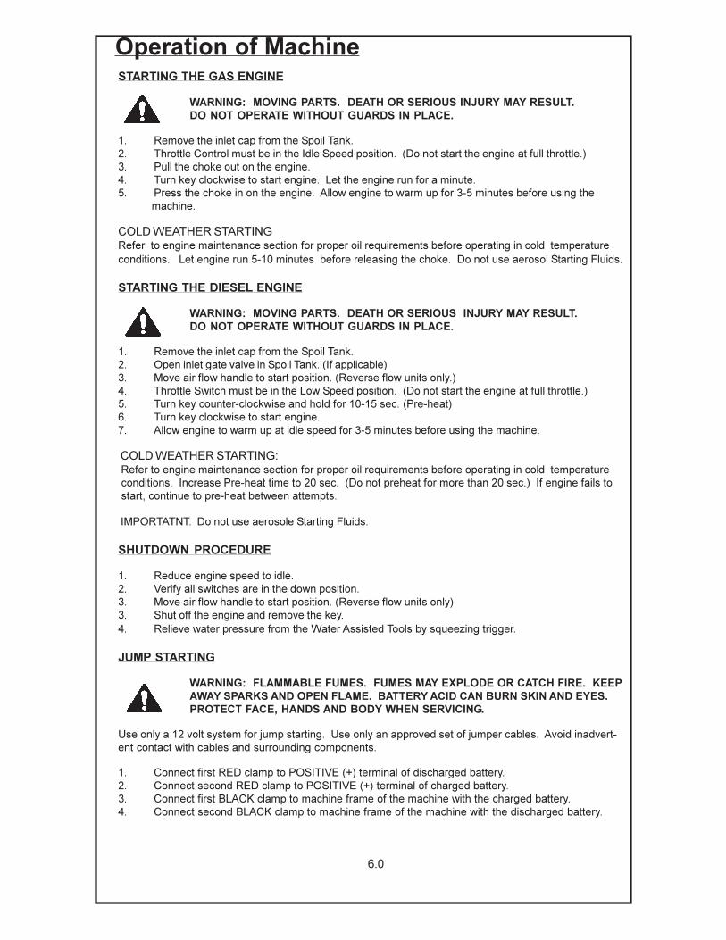
Operation of MachineSTARTING THE GAS ENGINE
WARNING: MOVING PARTS. DEATH OR SERIOUS INJURY MAY RESULT.
DO NOT OPERATE WITHOUT GUARDS IN PLACE.
1. Remove the inlet cap from the Spoil Tank.
2. Throttle Control must be in the Idle Speed position. (Do not start the engine at full throttle.)
3. Pull the choke out on the engine.
4. Turn key clockwise to start engine. Let the engine run for a minute.
5. Press the choke in on the engine. Allow engine to warm up for 3-5 minutes before using the
machine.
COLD WEATHER STARTINGRefer to engine maintenance section for proper oil requirements before operating in cold temperature
conditions. Let engine run 5-10 minutes before releasing the choke. Do not use aerosol Starting Fluids.
STARTING THE DIESEL ENGINE
WARNING: MOVING PARTS. DEATH OR SERIOUS INJURY MAY RESULT.
DO NOT OPERATE WITHOUT GUARDS IN PLACE.
1. Remove the inlet cap from the Spoil Tank.
2. Open inlet gate valve in Spoil Tank. (If applicable)
3. Move air flow handle to start position. (Reverse flow units only.)
4. Throttle Switch must be in the Low Speed position. (Do not start the engine at full throttle.)
5. Turn key counter-clockwise and hold for 10-15 sec. (Pre-heat)
6. Turn key clockwise to start engine.
7. Allow engine to warm up at idle speed for 3-5 minutes before using the machine.
COLD WEATHER STARTING: Refer to engine maintenance section for proper oil requirements before operating in cold temperature
conditions. Increase Pre-heat time to 20 sec. (Do not preheat for more than 20 sec.) If engine fails to
start, continue to pre-heat between attempts.
IMPORTATNT: Do not use aerosole Starting Fluids.
SHUTDOWN PROCEDURE
1. Reduce engine speed to idle.
2. Verify all switches are in the down position.
3. Move air flow handle to start position. (Reverse flow units only)
3. Shut off the engine and remove the key.
4. Relieve water pressure from the Water Assisted Tools by squeezing trigger.
JUMP STARTING
WARNING: FLAMMABLE FUMES. FUMES MAY EXPLODE OR CATCH FIRE. KEEP
AWAY SPARKS AND OPEN FLAME. BATTERY ACID CAN BURN SKIN AND EYES.
PROTECT FACE, HANDS AND BODY WHEN SERVICING.
Use only a 12 volt system for jump starting. Use only an approved set of jumper cables. Avoid inadvert-
ent contact with cables and surrounding components.
1. Connect first RED clamp to POSITIVE (+) terminal of discharged battery.
2. Connect second RED clamp to POSITIVE (+) terminal of charged battery.
3. Connect first BLACK clamp to machine frame of the machine with the charged battery.
4. Connect second BLACK clamp to machine frame of the machine with the discharged battery.

6.1
PRE-OPERATING INSTRUCTIONS
Before operating the vacuum system on a job site, the operator should be trained in slurry vacuum
excavation and cable locating. All sections of the maual should be read and understood. Prior to
beginning to excavate a hole, the operator should:
1. Check all fluid levels in the engine, vacuum pump, and water pump.
2. Check all vacuum hoses and tools for blockages and damage.
3. Check all filters and clean or replace as necessary.
CAUTION: DO NOT OPERATE WITHOUT FILTER SYSTEM INTACT.
4. Inspect all safety equipment, boots, gloves, etc. for wear and damage. Replace if necessary.
5. Check any utility maps for locations of buried utilities that need to be exposed.
6. If excavations are to be conducted near or on roadways, make sure local authorities are con-
tacted for regulations regarding traffic control and safety.
7. Know the contents of the material you are excavating or remediating.
8. Know the local regulations for disposing of liquid material and/or mud.
9. Have a place or a plan for the disposal of the material taken into the tank.
WARNING: DO NOT VACUUM HAZARDOUS OR FLAMMABLE MATERIAL
WITH THIS SYSTEM. CONSULT FEDERAL, STATE, AND LOCAL REGULATIONS
REGARDING CLASSIFICATIONS OF HAZARDOUS MATERIAL.
CONNECTING VACUUM HOSES AND TOOLING
1. Remove vacuum hose from storage.
2. Install male hose end into femalehose end on tank inlet port and lock the cam levers.
If there is a boom on the machine, attach the male hose end into the female hose end
on the end of the boom and lock the cam levers.
3. Attach additional vacuum hoses as needed for distance.
4. Remove the nessary tooling from the tool storage.
5. Attach necessary tooling onto the end of the vacuum hose and lock the cam levers.

6.2
JOB SITE PREPARATIONS
When pot-holing for non-destructive exposure of underground utilities prior to excavating, trenching
or boring, coordinate with all local utilities and mapping services. The area of the proposed excava-
tion should be marked. The one call service should have been contacted and the area marked or
cleared. Any underground plant owners not participating in the one call system should be notified
and have their underground facilities marked. Use a pipe and cable locator to do a search of the
area to be excavated to determine if any unmarked facilities exist. This may also help determine a
more precise location of any marked facilities. Consult area utility maps or seek advice on non-
metallic pipes such as sewer or storm water lines that may not be marked.
WARNING: WHEN EXPOSING UTILITY LINES FOR AVOIDANCE IN A DIGGING
APPLICATION, VERIFY THAT THE EXPOSED LINE IS THE CORRECT LINE.
EXCAVATIONS MAY CONTAIN MULTIPLE LINES OR ABANDONED LINES, AS
WELL AS THE LINE TO BE EXPOSED.
Establish and maintain traffic control procedures to keep the vacuum crew safe during the opera-
tion. Traffic cones or barricades should be used to establish a “safe” area around the vacuum
work site. When working in low light conditions, use work lights to illuminate the area and provide
visibility.
Determine the proper safety equipment to wear. When doing vacuum slurry excavation proper
safety equipment should be worn consisting of eye protection, high visual clothing or vest, hard
hat, gloves, ear protection and steel cap work boots. When doing vacuum slurry excavation
around energized power lines diaelectric insulated boots should be worn. This is to protect the
operator from becoming shocked or electrocuted if the reduction tool comes into accidental contact
with a leaking power line.
Electric boots should be maintained by following the manufacturer’s specific instructions. Read
and follow those directions carefully. They are contained in section 5 of this manual. Replace
worn out or torn boots. Always wear personal protective equipment including hard hat, reflective
vest, work boots and safety glasses. Ear protection should also be used when operating the
vacuum system.
WARNING: DO NOT WEAR LOOSE FITTING CLOTHING OR LONG HAIR.
THEY CAN BE SUCKED INTO THE VACUUM HOSE AND CAUSE SERIOUS
INJURY .
Keep bystanders and spectators away from the vacuum sytem and work site. Loose flying debris
can injure or blind bystanders. Allow only authorized personnel with proper safety equipment in the
work area.

6.3
POTHOLING EXCAVATION (Systems Supplied With Water Only)
Potholing excavation is achieved by use of the reduction tool. This tool combines the operations of
“reducing” and “removing” material from the ground. The end result being a small pothole that
allows for the visual identification of buried utilities. In the reduction step, high pressure water is
used to reduce the soil to a size small enough to be vacuumed. It is important to let the water do
the “reducing” of the soil so as not to damage the utility being exposed with the end of the tool. In
the removing step the “reduced” soil is vacuumed out of the excavated pothole.
To begin the job site operation:
1. Position the vacuum unit as close to the area to be excavated as possible.
2. Set the parking brake and chock wheels. (Trailer units must remain hooked to the towing
vehicle.)
3. Start the power unit and allow the engine to warm up. (Refer to the Start-Up Procedure in this
section of the manual.)
4. Place necessary traffic control measures.
5. Use proper personal safety protection equipment, including electric boots when necessary.
6. When preparing to pothole in a grassy area, use a spade or other appropriate digging tool to
loosen and remove the grass plug over the area to be excavated. If pot-holing under asphalt or
concrete, use a hydraulic or air operated breaker or saw to remove the top material and expose
the earth.
7. Connect the water line to the reduction tool.
8. Attach the vacuum hose to the reduction tool.
9. Attach the vacuum hose to the inlet port on the spoil tank. If additional hose is needed, attach
using the cam lock fittings provided on the hose ends. Short hose lengths are recommended
to reduce vacuum hose clogging. If the vacuum hose is connected to the spoil tank and the
engine is running, the reduction tool will be vacuuming. To stop the vacuuming, shut down the
engine on the power unit.
DANGER: SUFFOCATION HAZARD; WILL CAUSE SERIOUS INJURY OR
DEATH. KEEP HOSES AND VACUUM TOOLS AWAY FROM FACE AND BODY.
10. Turn on the water pump clutch and open the hose reel valve.
11. Position the reduction tool vertically at the desired potholling location.
12. Squeeze the reduction tool trigger lever and move the reduction tool in a semi-circular motion
with the handle. This will allow the water jets to excavate a cylindrical hole in the ground.
WARNING: FLYING OBJECTS CAN CAUSE SERIOUS INJURY OR
BLINDNESS. WEAR EYE PROTECTION.
WARNING: HIGH PRESSURE WATER CAN CAUSE SERIOUS INJURY.
WEAR PROTECTIVE CLOTHING AND DO NOT POINT HIGH PRESSURE
WATER TOOLS TOWARD BODY PARTS.
13. As the reduction step continues to expose the utility, be aware of changes in soil conditions. A
soft area that allows faster penetration will usually mean that the reduction tool is approaching
the utility. When resistance is encountered, stop. Remove the reduction tool from the pothole
and identify the utility or obstruction.
14. The jetting action of the reduction tool will also clear the underside of small utilities. If the utility
can not be completely exposed from one hole, the hole size must be enlarged to allow observa-
tion of the complete utility. It is important to be able to observe the entire utility to determine its
size.
15. The spoil tank is equipped with a “full tank” engine shut down sensor for fluid applications.
When the fluid level in the tank reaches capacity, a sensor will automatically shut down the
engine. This prevents overfilling the tank and sending fluid into the filtration system. When the
vacuum system automatically shuts down, empty spoil tank. (Refer to the section titled Empty-
ing the Spoil Tank.)
16. When finished potholeing, close the hose reel ball valve and turn off the water pump clutch.
The engine should be shut down if not shut down automatically and the key removed. Squeeze
the reduction tool trigger lever to release trapped water pressure prior to unhooking. All tools
and hoses should be securely stored before traveling to the spoil disposal site.

6.4
VACUUM EXCAVATION
Vacuum excavation is the process of removing material whether wet or dry by a powerful air
stream. This is accomplished use of the vacuum tool.
WARNING: DO NOT VACUUM HAZARDOUS MATERIAL WITH THIS SYSTEM.
CONSULT FEDERAL, STATE, AND LOCAL REGULATIONS REGARDING
CLASSIFICATIONS OF HAZARDOUS MATERIAL.
To begin the job site operation:
1. Position the vacuum unit as close to the area to be excavated as possible.
2. Set the parking brake and chock wheels.
3. Place necessary traffic control measures.
4. Start the power unit and allow the engine to warm up. (Refer to the Start-up Procedure in this
section of the manual.)
5. Use proper personal protection equipment.
6. Attach the vacuum hose to the vacuum tool.
7. Attach the vacuum hose to the inlet port on the spoil tank. If additional hose is needed, attach
using the cam lock fittings provided on the hose ends. Short hose lengths are recommended
to reduce vacuum hose clogging. If the vacuum hose is connected to the spoil tank and the
engine is running, the vacuum tool will be vacuuming. To stop the vacuuming, shut down the
engine on the power unit.
DANGER: SUFFOCATION HAZARD WILL CAUSE SERIOUS INJURY OR
DEATH. KEEP HOSES AND VACUUM TOOLS AWAY FROM FACE AND BODY.
8. When vacuuming fluids, it is more efficient to turn the liquid into an aerosol by not completely
submerging the remediation tool in the fluid. By keeping part of the vacuum tool out of the fluid,
the airflow through the vacuum tube will move the material quicker to the spoil tank. This
technique is also effective when vacuuming deep vertical distances.
9. The spoil tank is equipped with a “full tank” engine shut down sensor for fluid applications.
When the fluid level in the tank reaches capacity, a sensor will automatically shut down the
engine. This prevents overfilling the tank and sending fluid into the filtration system. When the
vacuum system automatically shuts down, empty spoil tank. (Refer to the section titled Empty-
ing the Spoil Tank.)
9. When vacuuming dry materials, the “fulll tank” shutdown sensor will not work. Vacuuming
should be stopped when the debris level in the spoil tank has reached the sight or when debris
can be heard circulating in the cyclone separator.
10. When finished, the engine should be shut down if not automatically shut down and the key
removed. All tools and hoses should be securely stored before traveling to the spoil disposal
site.

6.5
EMPTYING THE SPOIL TANK - MANUAL LOCKING DOOR
WARNING: DO NOT VACUUM HAZARDOUS MATERIAL WITH THIS SYSTEM.
CONSULT FEDERAL, STATE, AND LOCAL REGULATIONS REGARDING
CLASSIFICATIONS OF HAZARDOUS MATERIAL.
Emptying the vacuum spoil tank presents several hazards that the operator should be aware of.
DANGER: CRUSHING WEIGHT. SPOIL AND DOOR WILL CAUSE DEATH
AND SERIOUS INJURY. UNLOCK DOOR ONLY UNDER VACUUM. STAY
AWAY FROM DOOR WHEN DUMPING.
DANGER: CRUSHING WEGHT. ROLLING OR TILTING UNIT WILL CAUSE
DEATH NOR SERIOUS INJURY. CHOCK TIRES AND APPLY PARKING
BRAKE BEFORE OPERATING OR SERVICING. DO NOT OPERATE OR
SERVICE UNLESS ATTACHED TO VEHICLE.
Before beginning vacuum operations, a plan and site for disposing of the spoil in the tank
should be established.
1. Before arriving at the disposal site, verify the water tank has an adequate level for cleanup if
equipped.
2. After arriving at the disposal site, set the parking brake and chock the wheels.
3. Open the inlet port.
4. It is recommended that liquids be drained from the tank, prior to raising the tank. Use the 4”
gate valve located in the door to drain excess liquids.
5. At the operator’s console, click the vacuum tank full override switch on and make sure the
water pump clutch is off. Override is only required when the spoil tank full light is on.
6. Start the engine at low idle. Close the inlet port.
7. With the engine running at idle, and all inlet ports closed, vacuum will be reached when the
vacuum relief valve opens. A whistling sound is heard when the vacuum relief valve opens.
8. With the relief valve whistling, the door may be unlocked. Turn the door handle counterclock-
wise until fully loose.
9. Return to the operator controls and shut off the engine. Keep all personnel clear of the rear of
the unit. Wait for the vacuum to drop. As the vacuum drops, the door will release allowing the
spoil to dump from the tank.
10. Start the engine and raise the tank. The spoil in the tank is very heavy. Stay clear of the door
while raising the tank.
11. Once the tank has been emptied, it may be cleaned while in the raised position. Units not
cleaned after dumping should have the door seal and mating flange wiped clean of debris that
may damage the seal when sealilng the door.
12. Open the cyclone door and remove debris. Close the cyclone door.
13. The air filter should be cleaned once a day. Open the air filter door and inspect the air filter
element. If the air filter element is dirty, remove and clean with water. The air filter may be
cleaned with the spray wand. The cleaned air filter may be installed after it has been cleaned
and allowed to dry. Damaged air filters should be replaced immediatly. The unit should not be
opereated without the air filter element; damage to the blower will result.
14. Lower the tank. Turn the engine key counter-clockwise to the off position and remove the key.
15. Securely store all tools and hoses prior to leaving the spoil disposal site.

6.6
EMPTYING THE SPOIL TANK - HYDRAULIC LOCKING DOOR
WARNING: DO NOT VACUUM HAZARDOUS MATERIAL WITH THIS SYSTEM.
CONSULT FEDERAL, STATE, AND LOCAL REGULATIONS REGARDING
CLASSIFICATIONS OF HAZARDOUS MATERIAL.
Emptying the vacuum spoil tank presents several hazards that the operator should be aware of.
DANGER: CRUSHING WEIGHT. SPOIL AND DOOR WILL CAUSE DEATH
AND SERIOUS INJURY. UNLOCK DOOR ONLY UNDER VACUUM. STAY
AWAY FROM DOOR WHEN DUMPING.
DANGER: CRUSHING WEGHT. ROLLING OR TILTING UNIT WILL CAUSE
DEATH NOR SERIOUS INJURY. CHOCK TIRES AND APPLY PARKING
BRAKE BEFORE OPERATING OR SERVICING. DO NOT OPERATE OR
SERVICE UNLESS ATTACHED TO VEHICLE.
Before beginning vacuum operations, a plan and site for disposing of the spoil in the tank
should be established.
1. Before arriving at the disposal site, verify the water tank has an adequate level for cleanup if
equipped.
2. After arriving at the disposal site, set the parking brake and chock the wheels.
3. Open the inlet port.
4. It is recommended that liquids be drained from the tank, prior to raising the tank. Use the gate
valve located in the bottom of the door to drain excess liquids.
5. At the operator’s console, turn the vacuum tank full override switch on and make sure the water
pump clutch is off. Override is only required when the spoil tank is full.
6. Start the engine at low idle.
7. Press and hold the door open switch . The door will unlock and open.
8. Once the door is open, press and hold the tank raise switch.
9. Once the tank has been emptied, it may be cleaned while in the raised position. Units not
cleaned after dumping should have the door seal and mating flange wiped clean of debris that
may damage the seal when sealilng the door.
10. Open the cyclone door and remove debris. Close the cyclone door.
11. Lower the tank and close the door. Turn the engine key counter-clockwise to the off position
and remove the key.
12. The air filter should be cleaned once a day. Open the air filter door and inspect the air filter
element. If the air filter element is dirty, remove and clean with water. The air filter may be
cleaned with the spray wand. The cleaned air filter may be installed after it has been cleaned
and allowed to dry. Damaged air filters should be replaced immediatly. The unit should not be
opereated without the air filter element; damage to the blower will result.
13. Securely store all tools and hoses prior to leaving the spoil disposal site.

6.7
TANK CLEANING (Units supplied with a water system)
DANGER: CRUSHING WEGHT. ROLLING OR TILTING UNIT WILL CAUSE
DEATH OR SERIOUS INJURY. CHOCK TIRES AND APPLY PARKING BRAKE
BEFORE OPERATING OR SERVICING. DO NOT OPERATE OR SERVICE
UNLESS ATTACHED TO VEHICLE.
Units with spoil in the tank should follow the instructions for emptying the spoil tank before
proceding.
1. Start the engine.
2. With the tank empty and the door unlocked, raise the tank. (Models supplied with a hydraulic
locking door must install the door safety pin while working under the raised door.) (V100G/D
Models are supplied with a door holder to allow for access and cleaning.)
3. Attach the spray wand to the water hose.
4. Run the engine at high speed.
5. Turn the water pump clutch switch on.
6. Open the hose reel ball valve. (VSK100G/D model do not have a ball valve.)
WARNING: HIGH PRESSURE WATER FROM CAN CAUSE SERIOUS
INJURY. WEAR PROTECTIVE CLOTHING AND DO NOT POINT HIGH
PRESSURE WATER TOOLS TOWARD BODY PARTS.
7. The unit may now be cleaned with the spray wand and automatic tank cleanout if supplied.
Care should be taken when cleaning the door seal with the spray wand. The door seal may be
damaged if the spray wand is held in close proximity to the door seal or sprayed with high
pressure.
8. The automatic tank cleanout is operated by opening the tank cleanout ball valve. Material will be
washed out of the spoil tank. Close the tank cleanout valve when the tank is adequatly clean.
9. Close the hose reel ball valve and turn the water pump clutch switch off.
10. Release trapped water pressure in the water hose by squeezing the trigger on the spray
wand gun.
11. Lower the tank. Run the engine at low. Turn the key to the off position and remove the key.
12. Securely store all tools and hoses prior to departing.
TOOL AND HOSE CLEANING
All tools and hoses should be cleaned prior to storage. Debris build up on the tools and hoses will
reduce performance.
1. Connect the dirty tool and hoses to the spoil tank inlet.
2. Connect the spray wand to the high pressure water hose.
3. Start the engine and operate at high speed.
4. Turn the water pump clutch switch on.
5. Open the hose reel ball valve. (VSK100G/D model do not have a ball valve.)
WARNING: HIGH PRESSURE WATER FROM CAN CAUSE SERIOUS
INJURY. WEAR PROTECTIVE CLOTHING AND DO NOT POINT HIGH
PRESSURE WATER TOOLS TOWARD BODY PARTS.
6. Reduce the pressure on the spray wand to its minumum setting.
7. Use the spray wand to wash off the tool and hose. Material on the inside of the tool and hose
will be vacuumed into the spoil tank.
8. When finished, close the hose reel ball valve and turn the water pump clutch switch off.
9. Release trapped water pressure in the water hose by squeezing the trigger on the spray wand
gun.
10. Run the engine at low. Turn the engine off and remove the key.
11. Securely store all tools and hose prior to departing.

6.8
WATER SYSTEM FREEZE PROTECTION
All vacuum systems supplied with a water system should be filled with antifreeze if being stored or
transported in freezing conditions. Systems not filled with antifreeze are susceptible to freezing
water system damage.
UNITS SUPPLIED WITH WATER SYSTEMS ONLY
1. Remove the drain plug from the strainer and remove excess water from the system.
2. Reinsert the drain plug.
3. Verify no tools are connected to the high pressure water hose.
4. Place the end of the high pressure water hose in the water tank.
5. Units with antifreeze tanks should now close the ball valve at the water tank. Units not
supplied with an antifreeze tank must leave the ball valve at the water tank open.
6. Poor 1-2 gallons of antifreeze into the antifreeze tank and open the antifreeze ball valve. Units
supplied without an antifeeze tank should poor 2-3 gallons of antifeeze into the water tank.
CAUTION: DO NOT LET THE WATER PUMP RUN DRY. MAKE SURE A
LEVEL OF ANTIFREEZE IS VISIBLE AT ALL TIMES. RUNNING THE WATER
PUMP DRY WILL RESULT IN WATER PUMP DAMAGE.
7. Open the spoil tank inlet and start the engine. Operate the engine at low speed during
antifreezing.
8. Turn the water pump on.
9. Open the hose reel ball valve on units supplied with a hose reel.
10. Hold the antifreeze switch up.
11. Watch the flow coming out of the end of the water hose. Release the antifreeze switch as soon
as antifeeze is detected coming out of the hose. Remember not to let the antifreeze in the tank
to run completely out.
12. Close the hose reel ball valve on units supplied with a hose reel.
13. Units not supplied with the in-tank cleanout system skip to step 17.
14. Open the gate valve in the tank door and open the tank cleanout ball valve.
15. Hold the antifreeze switch up.
16. Watch the flow coming out the tank door valve. Release the antifreeze switch as soon as
antifreeze is detected. Close the gate valve in the tank door and close the tank cleanout valve.
17. Hold the antifreeze switch up.
18. Watch the flow returning to the water tank via the bypass hose. This can be seen by looking in
the water tank. Release the antifreeze switch when antifreeze is detected.
19. On units with an antifreeze tank, open the water tank ball valve allowing the excess antifreeze
to flow into the suction plumping. Close the antifreeze ball valve.
20. Turn off the water pump.
21. Turn the engine off. The system is antifreezed.

REVERSE FLOW
Reverse flow is used to unclog obstructions from hoses or remove debris from spoil tank.
1. When vacuuming, flow control valve is in vacuum position.
2. When clog occurs close gate valve on tank and or (optional) boom.
3. Move flow directional valve to pressure.
4. Allow system to build to 5 p.s.i., pressure relief valve will now allow
system to go passed 5 p.s.i.
5. Make sure hose is positioned in safe direction.
6. Open gate valve to the obstructed hose.
7. Once obstruction is relieved return flow control valve into vacuum.
REMOVING DEBRIS FROM SPOIL TANK
1. Attach hose to lower gate valve to transfer spoil material from tank to designated ares.
2. Make sure flow control valve is in neutral.
3. Start the unit and put the unit in high throttle.
4. Move the control flow valve to pressure.
5. Open the lower gate valve with hose attached and pointed in safe direction.
6. Place the flow valve back into neutral.
7. Close bottom gate valve and turn machine off.
8. At this point operator can either go back to work or remove solid waste from the tank.
BOOM
Boom is for maneuvering suction hose and not a lifting mechanism or device.
1. Remove the remote from the curbside door.
2. Start the unit and switch throttle to high.
3. Using the remote, raise the boom so it clears all obstruction in the travel path.
4. Use the remote to unlock the pin on manual boom and grab the rope to swing the boom into position.
5. Let go of button to lock pin into place.
6. (Hydraulic Boom) Use the remote to move boom into desired position.
7. Using the remote lower the boom so the hose handle can be easily removed and first section of
hose can easily be attached.
8. Attach first section of hose then raise the boom to attach second section of hose. Attach hose
handle to the lowest section of hose at an easy operating position and attach the remote for easy
operation.
9. At this point boom is ready for operational use.
6.9

CLEAN UP
1. Remove hose handle and remote and then remove first section of hose. Lower the boom to a
position to easily remove second section of hose.
2. Retract boom and Raise boom to clear all obstruction in travel path. Unlock pin and swing boom
back into position on top of bracket.
3. Clean hoses and place them into designated storage space.
4. Lower engine throttle and turn off engine. Store the remote back into place inside door.
6.10

0% H2O 25% H2O 50% H2O 75% H2O
Specific lb. per lb. per kg. per
Gravity cu. Foot cu. Yard cu. Meter lb. per Gal. lb. per Gal. lb. per Gal. lb. per Gal.
Earth, loam, dry, excavated 1.25 78 2106 1249 10.4 9.9 9.36 8.83
Earth, moist, excavated 1.44 90 2430 1442 12 11.1 10.17 9.23
Sand, loose 1.44 90 2430 1442 12 11.1 10.17 9.23
Caliche 1.44 90 2430 1442 12 11.1 10.17 9.23
Earth, packed 1.52 95 2565 1522 12.7 11.6 10.5 9.4
Earth, wet, excavated 1.6 100 2700 1601 13.4 12.1 10.83 9.57
Sand, dry 1.6 100 2700 1601 13.4 12.1 10.83 9.57
Clay, wet lump 1.6 100 2700 1601 13.4 12.1 10.83 10.83
Sand, rammed 1.68 105 2835 1682 14 12.6 11.17 9.73
Gravel, dry, 1/4 to 2 inch 1.68 105 2835 1682 14 12.6 11.17 9.73
Earth, soft loose mud 1.73 108 2916 1730 14.4 12.9 11.37 9.83
Sand and Gravel, dry 1.73 108 2916 1730 14.4 12.9 11.37 9.83
Clay, wet excavated 1.83 114 3078 1826 15.2 13.51 11.77 10.04
Sand, water filled/wet 1.92 120 3240 1922 16 14.11 12.17 10.24
Earth, dense 2 125 3375 2002 16.7 14.61 12.51 10.4
Sand and Gravel, wet 2 125 3375 2002 16.7 14.61 12.51 10.4
Gravel, wet, 1/4 to 2 inch 2 125 3375 2002 16.7 14.61 12.51 10.4
Sand, wet packed 2.08 130 3510 2082 17.4 15.11 12.84 10.57
1. Material type
2. Material purity
3. Compaction
4. Water Content
5. PSI of water wand
6. GPM of water flow
7. CFM of vacuum
8. IN/HG of vacuum
9. Individual operator
MATERIAL DENSITY CHART AEM Vacuum Excavation Equipment Committee
VARIABLES AFFECTING VOLUME OF H2O REQUIRED FOR EXCAVATION
Source: Pocket Ref by Thomas J. Glover, Copyright 1989 1999, 2nd Edition, pg 427 436
NOTE: The weight of H2O is 8.3 lb. per Gal.
6.11

LIMITED WARRANTYThe Manufacturer warrants its products to be free from defects in material and workmanship for a
period of twelve months from the date of shipment from the factory. The Manufacturer shall not be
responsible for any damage resulting to or caused by its products by reason of installation, improper
storage, unauthorized service, alteration of the products, neglect or abuse, or use of the product in a
manner inconsistent with its design. This warranty does not extend to any component parts not
manufactured by Manufacturer; however, Manufacturer’s warranty herein shall not limit any warran-
ties made by manufacturers of component parts which extend to Buyer.
Claims for defects in material and workmanship shall be made in writing to Manufacturer within ten
days of discovery of defect. Manufacturer may either send a service representative or have the prod-
uct returned to its factory at Buyer’s expense for inspection. Upon notification of defect, Manufacturer
will issue a return goods authorization number to Buyer. The return goods authorization number must
accompany the product returned. If judged by the Manufacturer to be defective in material or work-
manship, the product will be replaced or repaired at the option of the manufacturer, free from all
charges except authorized transportation. Buyer shall be responsible for all maintenance services
consisting of lubrication and cleaning of equipment, replacing expandable parts, making minor adjust-
ments, and performing operating checks, all in accordance with procedures outlined in Manufacturer’s
maintenance literature.
THE FOREGOING WARRANTY IS IN LIEU OF ALL OTHER WARRANTIES AND NO REPRESENTA-
TIONS, GUARANTEES, OR WARRANTIES, EXPRESS OR IMPLIED, (INCLUDING BUT NOT LIM-
ITED TO A WARRANTY OF MERCHANTABILITY OR FITNESS FOR A PARTICULAR PURPOSE),
ARE MADE BY THE MANUFACTURER IN CONNECTION WITH THE MANUFACTURE OR SALE OF
ITS PRODUCTS. NO EMPLOYEE, DISTRIBUTOR, OR REPRESENTATIVE IS AUTHORIZED TO
CHANGE THIS WARRANTY ON BEHALF OF MANUFACTURER THE REMEDIES OF BUYER SET
FORTH HEREIN ARE EXCLUSIVE AND ARE IN LIEU OF ALL OTHER REMEDIES. THE LIABILITY
OF MANUFACTURER WHETHER IN CONTRACT, TORT, UNDER ANY WARRANTY, OR
OTHERWISE SHALL NOT EXTEND BEYOND ITS OBLIGATION TO REPAIR OR REPLACE, AT ITS
OPTION ANY PRODUCT OR PART FOUND BY MANUFACTURER TO BE DEFECTIVE IN MATE-
RIAL OR WORKMANSHIP. MANUFACTURER SHALL NOT BE LIABLE FOR COST OF INSTALLA-
TION AND/OR REMOVAL OR BE RESPONSIBLE FOR DIRECT, INDIRECT, SPECIAL OR CONSE-
QUENTIAL DAMAGES OF ANY NATURE.
GENERAL RETURNS OF MERCHANDISE
1. All returns must be pre-authorized
A. Please call our parts department for an RGA number
B. Please include RGA number on the outside of box
C. Include any required paper work or special instructions
D. Items returned without an RGA number will not be accepted
2. All returns are subject to a 20% restock charge.
3. Special items are non-returnable
A. Non-stock parts
B. Custom parts
C. If you are unsure about a parts status when ordering, ask your McLaughlin representative
if the item fits on of the above conditions.
4. Items must be returned within thirty days of original order date.
5. Items not returned within 30 days from the date of RGA is issued will not be accepted.
6. The item(s) must be in new condition. Used item(s) are not returnable.
WARRANTYRETURN GOODS POLICY
7.0

8.0
Maintenance Record
DATE SERVICE PERFORMED BY________ _______________________________________ _________________________
________ _______________________________________ _________________________
________ _______________________________________ _________________________
________ _______________________________________ _________________________
________ _______________________________________ _________________________
________ _______________________________________ _________________________
________ _______________________________________ _________________________
________ _______________________________________ _________________________
________ _______________________________________ _________________________
________ _______________________________________ _________________________
________ _______________________________________ _________________________
________ _______________________________________ _________________________
________ _______________________________________ _________________________
________ _______________________________________ _________________________
________ _______________________________________ _________________________
________ _______________________________________ _________________________
________ _______________________________________ _________________________
________ _______________________________________ _________________________
________ _______________________________________ _________________________
________ _______________________________________ _________________________
________ _______________________________________ _________________________
________ _______________________________________ _________________________
________ _______________________________________ _________________________
________ _______________________________________ _________________________
________ _______________________________________ _________________________
________ _______________________________________ _________________________
________ _______________________________________ _________________________
________ _______________________________________ _________________________
________ _______________________________________ _________________________
________ _______________________________________ _________________________
________ _______________________________________ _________________________

8.1
Notes
_______________________________________________________________________________________________________________________________________
_________________________________________________________________________
_________________________________________________________________________
________________________________________________________________________
________________________________________________________________________
_________________________________________________________________________
________________________________________________________________________
________________________________________________________________________
________________________________________________________________________
________________________________________________________________________
________________________________________________________________________
________________________________________________________________________
_________________________________________________________________________
_________________________________________________________________________
_________________________________________________________________________
______________________________________________________________________________________________________________________________________
_________________________________________________________________________
_________________________________________________________________________
________________________________________________________________________
________________________________________________________________________
__________________________________________________________________________
________________________________________________________________________
________________________________________________________________________
________________________________________________________________________
________________________________________________________________________
_________________________________________________________________________
_____________________________________________________________________________
_________________________________________________________________________
_________________________________________________________________________
________________________________________________________________________
______________________________________________________________________________________________________________________________________
________________________________________________________________________
_________________________________________________________________________
________________________________________________________________________
________________________________________________________________________
_________________________________________________________________________
________________________________________________________________________
________________________________________________________________________
_________________________________________________________________________
________________________________________________________________________
________________________________________________________________________
________________________________________________________________________
________________________________________________________________________
________________________________________________________________________
________________________________________________________________________
________________________________________________________________________
________________________________________________________________________
___________________________________________________________________________________________
________________________________________________________________________


![Fault [Read-Only] - Washington State · PDF fileForward Voltage Drop & Takagi From the previous fault location algorithms we developed the forward voltage drop equation](https://img.pdfslide.us/doc/110x75/5abaf4827f8b9a8f058bf365/fault-read-only-washington-state-voltage-drop-takagi-from-the-previous-fault.jpg)