Embed Size (px)
Citation preview
Doc. Ref.: QSP-FE-03-22 AUGUST 2001 Page 1
SAFOP Guidelines
Doc. Ref.: QSP-FE-03-22
August 2001 Page 2
TABLE OF CONTENTS
1 INTRODUCTION .......................................................................................................... 5
1.1 SCOPE ...............................................................................................................................5
2 DEFINITIONS................................................................................................................ 7
2.1 GENERAL...........................................................................................................................7 2.2 TECHNICAL........................................................................................................................7 2.3 ABBREVIATIONS ...............................................................................................................9 2.4 REFERENCES ...................................................................................................................9
3 SAFOP STUDIES GENERAL PRINCIPLES ............................................................... 10
3.1 TYPES OF STUDIES........................................................................................................10 3.1.1 Safety Analysis (SAFAN) ..................................................................................................10 3.1.2 Security and Operability Analysis (SYSOP) ......................................................................10 3.1.3 Operator Task Analysis (OPTAN).....................................................................................10 3.2 TIMING OF STUDIES.......................................................................................................10 3.2.1 Initial Study........................................................................................................................10 3.2.2 Final Study ........................................................................................................................10 3.3 SAFOP TEAM COMPOSITION ........................................................................................10 3.3.1 General .............................................................................................................................10 3.3.2 Leader...............................................................................................................................10 3.3.3 Secretary...........................................................................................................................11 3.3.4 Members ...........................................................................................................................11 3.3.5 Training .............................................................................................................................12 3.4 STUDY EXECUTION........................................................................................................12 3.4.1 General .............................................................................................................................12 3.4.2 Methods ............................................................................................................................12 3.4.3 Environment......................................................................................................................12 3.5 PREPARATIVE WORK ....................................................................................................13 3.5.1 General .............................................................................................................................13 3.5.2 Initial Study........................................................................................................................13 3.5.3 Final Study ........................................................................................................................13 3.6 RECORDING ....................................................................................................................13 3.6.1 Worksheets.......................................................................................................................13 3.7 FOLLOW-UP ....................................................................................................................13 3.7.1 Recommended Actions.....................................................................................................13
4 SAFETY ANALYSIS (SAFAN) .................................................................................... 15
4.1 GENERAL.........................................................................................................................15 4.1.1 Study Phases ....................................................................................................................15 4.2 STUDY TECHNIQUE........................................................................................................15 4.3 PROCEDURE ...................................................................................................................15 4.4 RECOMMENDED ACTIONS............................................................................................16 4.5 EXAMPLES.......................................................................................................................16 4.5.1 Safety Analysis (Outside Persons)....................................................................................16 4.5.2 Safety Analysis (Non-Electrical SPDC Staff) ....................................................................17 4.5.3 Safety Analysis (Electrical SPDC Staff) ............................................................................17
Doc. Ref.: QSP-FE-03-22 AUGUST 2001 Page 3
5 SYSTEM SECURITY AND OPERABILITY OF PLANT ANALYSIS (SYSOP) ............. 23
5.1 GENERAL.........................................................................................................................23 5.1.1 Study Phases ....................................................................................................................23 5.2 STUDY TECHNIQUE........................................................................................................23 5.2.1 Element Selection .............................................................................................................23 5.2.2 Component Method ..........................................................................................................23 5.2.3 Assessment Point Method ................................................................................................24 5.2.4 Consequences and Results ..............................................................................................24 5.3 STUDY PROCEDURE......................................................................................................24 5.3.1 General .............................................................................................................................24 5.4 RECOMMENDED ACTIONS............................................................................................25 5.5 EXAMPLES.......................................................................................................................25 5.5.1 Component Method ..........................................................................................................25 5.5.2 Assessment Point Method ................................................................................................26
6 OPERATOR TASK ANALYSIS (OPTAN).................................................................... 38
6.1 GENERAL.........................................................................................................................38 6.1.1 Study Phases ....................................................................................................................38 6.2 STUDY TECHNIQUE........................................................................................................38 6.3 STUDY PROCEDURE......................................................................................................39 6.4 RECOMMENDATIONS.....................................................................................................39 6.5 EXAMPLES.......................................................................................................................40 6.5.1 Control Room Operator Task Analysis .............................................................................40 6.5.2 Field Operator Task Analysis............................................................................................40
APPENDIX 1 – NOTES OF GUIDANCE FOR SAFOP TEAM LEADERS...................................44
APPENDIX 2 – NOTES OF GUIDANCE FOR SAFOP TEAM SECRETARIES ..........................46
APPENDIX 3 – CONTROL ROOM OPERATOR'S MAIN TASKS QUESTIONNAIRE ............47
APPENDIX 4 – FIELD 0PERATOR'S MAIN TASKS QUESTIONNAIRE.....................................50
7 ENGINEERING STANDARD USER-COMMENT FORM ............................................ 52
SAFOP Guidelines
Doc. Ref.: QSP-FE-03-22
August 2001 Page 4
Figure 1-1 - SAFOP STUDY INPUTS AND RESULTS ..........................................................................6 Figure 3-1 - SAFOP STUDY TEAM COMPOSITION...........................................................................11 Figure 3-2 - SAFOP STUDY SEQUENCE ...........................................................................................14 Figure 4-1 - SAFAN GUIDE WORDS AND PROMPT WORDS ..........................................................18 Figure 4-2 - SAFAN STUDY SEQUENCE............................................................................................19 Figure 5-1 - SYSOP GUIDE WORDS AND PROMPT WORDS..........................................................27 Figure 5-2 - SYSOP COMPONENT ASSEMBLY METHOD …………………………………………… 28 Figure 5-3 - SYSOP ELEMENT ASSESSMENT POINT STUDY SEQUENCE ...................................29 Figure 5-4 - ELECTRICAL SYSTEM POSSIBLE ELEMENT AND STUDY SEQUENCE ....................30 Figure 5-5 - 33 KV FEEDER CIRCUIT ELEMENT...............................................................................31 Figure 5-6 - 132 KV AND 33 KV BUSBAR ELEMENTS.......................................................................32 Figure 5-7 - 132/33 20 MVA TRANSFORMER ELEMENT ..................................................................33 Figure 5-8 - OVERHEAD TRANSMISSION LINE ELEMENT. .............................................................34 Figure 5-9 - 132/33 KV TRANSFORMER ELEMENT ASSESSMENT POINTS ..................................35 Figure 6-1 - OPTAN STUDY SEQUENCE ...........................................................................................41 Checksheet SAFETY ANALYSIS (SAFAN)…………………………………………………………………20 Worksheet SAFETY ANALYSIS (SAFAN) ………………………………………………………………….22 Checksheet SYSTEM SECURITY AND OPERABILITY (SYSOP) ……………………………………..36 Worksheet SYSTEM SECURITY AND OPERABILITY (SYSOP) ……………………………………….37 Checksheet OPERATOR TASK ANALYSIS (OPTAN) …………………………………………………..40 Worksheet OPERATOR TASK ANALYSIS (OPTAN) …………………………………………………….42
Doc. Ref.: QSP-FE-03-22 AUGUST 2001 Page 5
1 INTRODUCTION
This guide describes a series of studies that shall be used during various phases of a major project being engineered to design, install and operate high voltage generation, transmission and distribution electrical installation, within Shell Petroleum Development Company of Nigeria Ltd. (SPDC). These studies are collectively designated as a 'Safety and Operability (SAFOP) Study' and are internationally established for use in the petrochemical industry. Individual studies can be applied to assist in clarifying objectives of the installation, selection of plant and equipment and its use in terms of system security and operability. Additionally, one of the studies helps to identify major hazards to different groups of personnel inherent in construction, commissioning and operation of high voltage electrical systems.
1.1 SCOPE
A SAFOP is performed to provide a formal framework for a searching and systematic examination of engineering design in terms of effective operation and safety of personnel, using information provided by SPDC project staff, their Consultants, plant Manufacturers and relevant Government agencies (Federal Ministry of Power and Steel - FMPS and National Electric Power Authority - NEPA) where interface exist.
A SAFOP study does not include detailed analysis of design calculations, design data (e.g., checking of protection settings, etc.) stipulated by engineering design Consultants nor any initial review of a Manufacturer's design capabilities (such as test certificates for items of plant, etc.).
A SAFOP shall form part of the project work scope for projects which do change the configuration of the SPDC High Voltage power generation and transmission system, or when new loads are connected to the system with a total installed capacity in excess of 1 MVA. In other cases, the SPDC Corporate Discipline Head Electrical may still decide to include a SAFOP study in a project scope, depending on the possible impact on power system integrity and operability. The project RFQ shall mention the requirement for the inclusion of a SAFOP study. Objectives of a SAFOP Study are summarised as to:
• Assess and minimise types of potential hazard presented to personnel in the vicinity of electrical installations.
• Provide a critical review of both network design and plant to be installed and assess any limitations and their effects on both operability and security of the overall system.
• Analyse tasks set for operators assess facilities and instructions provided to undertake these tasks and recommend measures to avoid operator error.
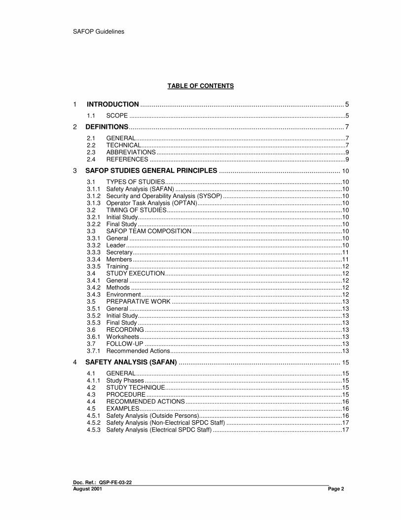
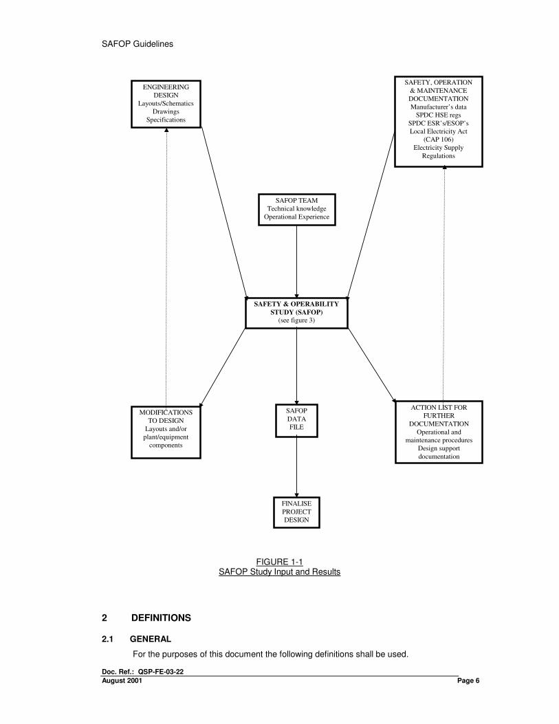
It is not the intention of this study guide to duplicate design work provided by SPDC’s Consultants or turnkey Contractors, but it is intended that SAFOP Studies should complement engineering design by providing overall assessments of final design from an operational view point. An overview of inputs to, and results sought from a Safety and Operability Study (SAFOP) is illustrated in FIGURE 1-1.
SAFOP Guidelines
Doc. Ref.: QSP-FE-03-22
August 2001 Page 6
FIGURE 1-1 SAFOP Study Input and Results
2 DEFINITIONS
2.1 GENERAL
For the purposes of this document the following definitions shall be used.
ENGINEERING
DESIGN
Layouts/Schematics
Drawings
Specifications
SAFETY, OPERATION
& MAINTENANCE
DOCUMENTATION
Manufacturer’s data
SPDC HSE regs
SPDC ESR’s/ESOP’s
Local Electricity Act
(CAP 106)
Electricity Supply
Regulations
SAFOP TEAM
Technical knowledge
Operational Experience
SAFETY & OPERABILITY
STUDY (SAFOP)
(see figure 3)
MODIFICATIONS
TO DESIGN
Layouts and/or
plant/equipment
components
SAFOP
DATA
FILE
FINALISE
PROJECT
DESIGN
ACTION LIST FOR
FURTHER
DOCUMENTATION
Operational and
maintenance procedures
Design support
documentation
Doc. Ref.: QSP-FE-03-22 AUGUST 2001 Page 7
Shall - The word 'shall' is to be understood as mandatory. Should - The word 'should' is to be understood as strongly recommended. May - The word 'may' is to be understood as indicating a possible course of
action. The Company - Shell Petroleum Development Company of Nigeria Ltd. User - A specified engineer or Consultant who applies these Standards in the
execution of SPDC project. The Consultant - The party to the contract with the Company who is responsible for
providing the design, engineering and other related consultation services under the contract.
The Contractor - The party to the Contract with the Company who is responsible for the
construction and other related works specified in the contract. On occasion, for example in 'turnkey contracts' the contractor may be responsible for design, engineering, manufacture, shipment, supply, installation, testing, commissioning and performance guarantee up to the defects liability period as defined in the individual contract.
Manufacturer - The party responsible for the manufacture of equipment and services to
perform the duties specified by the Consultant or Company. Vendor/Supplier - A party responsible for the supply of equipment, materials or product-
related services in accordance with the Purchase Order issued by SPDC or its nominated Contractor.
Works - All Works to be executed and all services to be rendered by a
Contractor under the terms of a Contract. Work-site - A defined place designated by the Company whereat all Works and a
Contractor under a Contract shall execute services.
2.2 TECHNICAL
Assessment Point - Assessment points are defined locations within an Element to which a known deviation is assigned.
Checksheet - Record attention points which have to be worked out at the Worksheet Component - An item of plant or equipment that when combined with other
components forms an ‘Element’. Control - All means by which an Operator gives instructions or institutes actions. -cont.- Deviation - Departure from the normal design function of an Element or
Component. Display - Methods of giving visual or graphic information to an operator. ESOP - Electrical Safety Operational Procedure are instructions that are issued
to supplement the SPDC Electrical Safety Rules. ESR - Electrical Safety Rules ref.: Safety Manual appendix VII
SAFOP Guidelines
Doc. Ref.: QSP-FE-03-22
August 2001 Page 8
Element - Major part of an electrical installation that is large enough to be of interest in terms of the study objective.
Function - Definition of the design and operating intention of plant or equipment
under both normal and abnormal running conditions. Guide-word - Label or distinctive word used to focus attention of a SAFOP study
team on possible Deviations and their consequences. Hazard - Danger to persons or electrical components which could cause injury,
damage or other form of loss. Information - Recorded plant data. Key Task - Identification of chief task under the three main Operator duties
headings. Keyword - Identification of a hazard that may occur in an electrical installation and
present danger to personnel or environment. Monitor - Survey and assess all displays. Procedure - This term may include general operating guidance, aid to meet
operating aims and a specified series of actions to achieve a given result.
Prompt-word - Word chosen to help a study team to identify possible deviations or
consequences associated with a selected Guideword. Protect - To monitor system parameters and automatically initiate disconnection
of a circuit under fault conditions. Resources - Means of aid or support, knowledge understanding and training. SAFOP Study - Safety and Operability Study is the application of a series of technical
examinations and audits to assess hazard potential to personnel and plan of mistaken operation of a system or malfunction of individual components and consequential effects including operator error.
SCADA - Supervisory Control and Data Acquisition, i.e., to provide remote
system control and data acquisition. Study Definition - Statement of object and scope of study. Worksheet - Formally recorded results and recommendations obtained during
SAFOP study.
2.3 ABBREVIATIONS
ESR - Electrical Safety Rules. ESOP - Electrical Safety Operational Procedure. FMPS - Federal Ministry of Power and Steel HAZOP - Hazard and Operability Study. NEPA - National Electric Power Authority OPTAN - Operator Task Analysis. RFQ Request for Quotation (project work scope) SAFAN - Safety Analysis.
SCADA - Supervisory Control and Data Acquisition. SIEP - Shell International Exploration and Production B.V.
Doc. Ref.: QSP-FE-03-22 AUGUST 2001 Page 9
SIOP - Shell International Oil Products B.V. SPDC - Shell Petroleum Development Company of Nigeria Ltd. UKEA - United Kingdom Electrical Association. VDU - Visual Display Unit.
2.4 REFERENCES
SIPM EP 23/5 - Guidance on Hazard and Operability (HAZOP) Studies revised edition 1983.
Safety and Reliability Directorate -
Guide to Reducing Human Error in Process Operation (UKEA) February 1985 SRD R347
CISHEC Safety Committee -
A Guide to Hazard and Operability Studies (1979)
3 SAFOP STUDIES GENERAL PRINCIPLES
3.1 TYPES OF STUDIES
Three completely different types of studies are necessary to fully meet objectives of a complete SAFOP study and these can be summarised as follows.
3.1.1 Safety Analysis (SAFAN)
A SAFAN examines hazards always present in construction, commissioning and operation of high voltage electrical installations and considers them in relation to safety of personnel who are to operate, work or even be in the vicinity of overhead lines and substations being engineered under a project.
3.1.2 Security and Operability Analysis (SYSOP)
A SYSOP reviews briefly standards of overall network design and assesses security of supply provided to different user groups fed from high voltage systems. It examines main items of plant and their auxiliaries planned to be installed and consider any limitations found and their effect on system operability.
SAFOP Guidelines
Doc. Ref.: QSP-FE-03-22
August 2001 Page 10
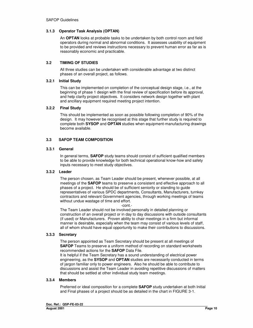
3.1.3 Operator Task Analysis (OPTAN)
An OPTAN looks at probable tasks to be undertaken by both control room and field operators during normal and abnormal conditions. It assesses usability of equipment to be provided and reviews instructions necessary to prevent human error as far as is reasonably economic and practicable.
3.2 TIMING OF STUDIES
All three studies can be undertaken with considerable advantage at two distinct phases of an overall project, as follows.
3.2.1 Initial Study
This can be implemented on completion of the conceptual design stage, i.e., at the beginning of phase 1 design with the final review of specification before its approval, and help clarify project objectives. It considers network design together with plant and ancillary equipment required meeting project intention.
3.2.2 Final Study
This should be implemented as soon as possible following completion of 90% of the design. It may however be recognised at this stage that further study is required to complete both SYSOP and OPTAN studies when equipment-manufacturing drawings become available.
3.3 SAFOP TEAM COMPOSITION
3.3.1 General
In general terms, SAFOP study teams should consist of sufficient qualified members to be able to provide knowledge for both technical operational know-how and safety inputs necessary to meet study objectives.
3.3.2 Leader
The person chosen, as Team Leader should be present, whenever possible, at all meetings of the SAFOP teams to preserve a consistent and effective approach to all phases of a project. He should be of sufficient seniority or standing to guide representatives of various SPDC departments, Consultants, Manufacturers, turnkey contractors and relevant Government agencies, through working meetings of teams without undue wastage of time and effort.
-cont.- The Team Leader should not be involved personally in detailed planning or construction of an overall project or in day to day discussions with outside consultants (if used) or Manufacturers. Proven ability to chair meetings in a firm but informal manner is desirable, especially when the team may consist of various levels of staff, all of whom should have equal opportunity to make their contributions to discussions.
3.3.3 Secretary
The person appointed as Team Secretary should be present at all meetings of SAFOP Teams to preserve a uniform method of recording on standard worksheets recommended actions for the SAFOP Data File. It is helpful if the Team Secretary has a sound understanding of electrical power engineering, as the SYSOP and OPTAN studies are necessarily conducted in terms of jargon familiar only to power engineers. Also he should be able to contribute to discussions and assist the Team Leader in avoiding repetitive discussions of matters that should be settled at other individual study team meetings.
3.3.4 Members
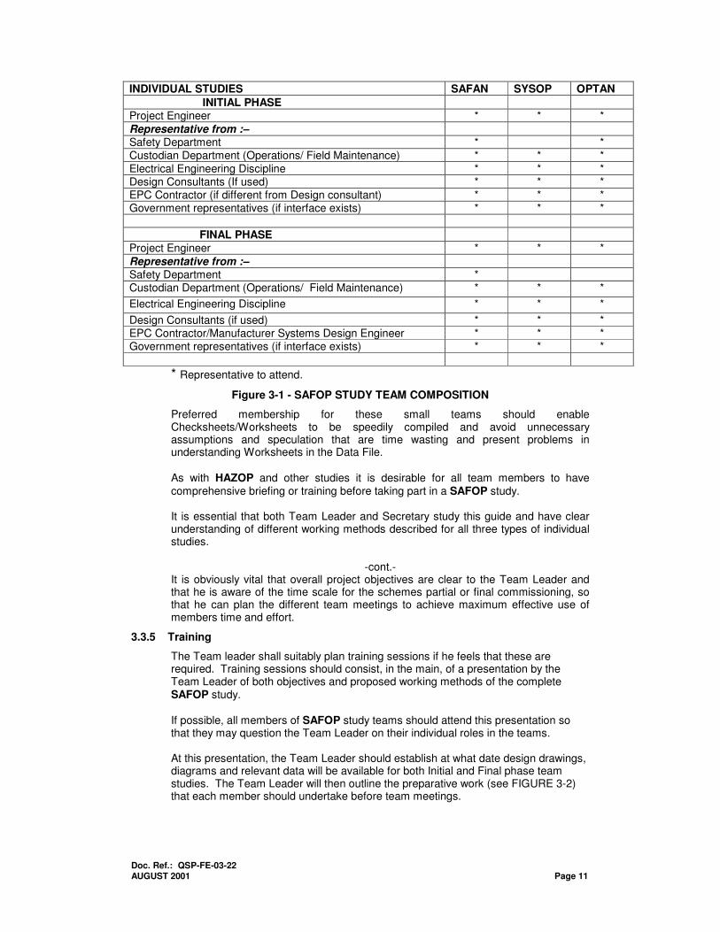
Preferred or ideal composition for a complete SAFOP study undertaken at both Initial and Final phases of a project should be as detailed in the chart in FIGURE 3-1.
Doc. Ref.: QSP-FE-03-22 AUGUST 2001 Page 11
INDIVIDUAL STUDIES SAFAN SYSOP OPTAN
INITIAL PHASE
Project Engineer * * *
Representative from :–
Safety Department * * Custodian Department (Operations/ Field Maintenance) * * *
Electrical Engineering Discipline * * * Design Consultants (If used) * * * EPC Contractor (if different from Design consultant) * * * Government representatives (if interface exists) * * *
FINAL PHASE
Project Engineer * * *
Representative from :–
Safety Department * Custodian Department (Operations/ Field Maintenance) * * *
Electrical Engineering Discipline * * *
Design Consultants (if used) * * * EPC Contractor/Manufacturer Systems Design Engineer * * * Government representatives (if interface exists) * * *
* Representative to attend.
Figure 3-1 - SAFOP STUDY TEAM COMPOSITION
Preferred membership for these small teams should enable Checksheets/Worksheets to be speedily compiled and avoid unnecessary assumptions and speculation that are time wasting and present problems in understanding Worksheets in the Data File. As with HAZOP and other studies it is desirable for all team members to have comprehensive briefing or training before taking part in a SAFOP study. It is essential that both Team Leader and Secretary study this guide and have clear understanding of different working methods described for all three types of individual studies.
-cont.- It is obviously vital that overall project objectives are clear to the Team Leader and that he is aware of the time scale for the schemes partial or final commissioning, so that he can plan the different team meetings to achieve maximum effective use of members time and effort.
3.3.5 Training
The Team leader shall suitably plan training sessions if he feels that these are required. Training sessions should consist, in the main, of a presentation by the Team Leader of both objectives and proposed working methods of the complete SAFOP study. If possible, all members of SAFOP study teams should attend this presentation so that they may question the Team Leader on their individual roles in the teams. At this presentation, the Team Leader should establish at what date design drawings, diagrams and relevant data will be available for both Initial and Final phase team studies. The Team Leader will then outline the preparative work (see FIGURE 3-2) that each member should undertake before team meetings.
SAFOP Guidelines
Doc. Ref.: QSP-FE-03-22
August 2001 Page 12
3.4 STUDY EXECUTION
3.4.1 General
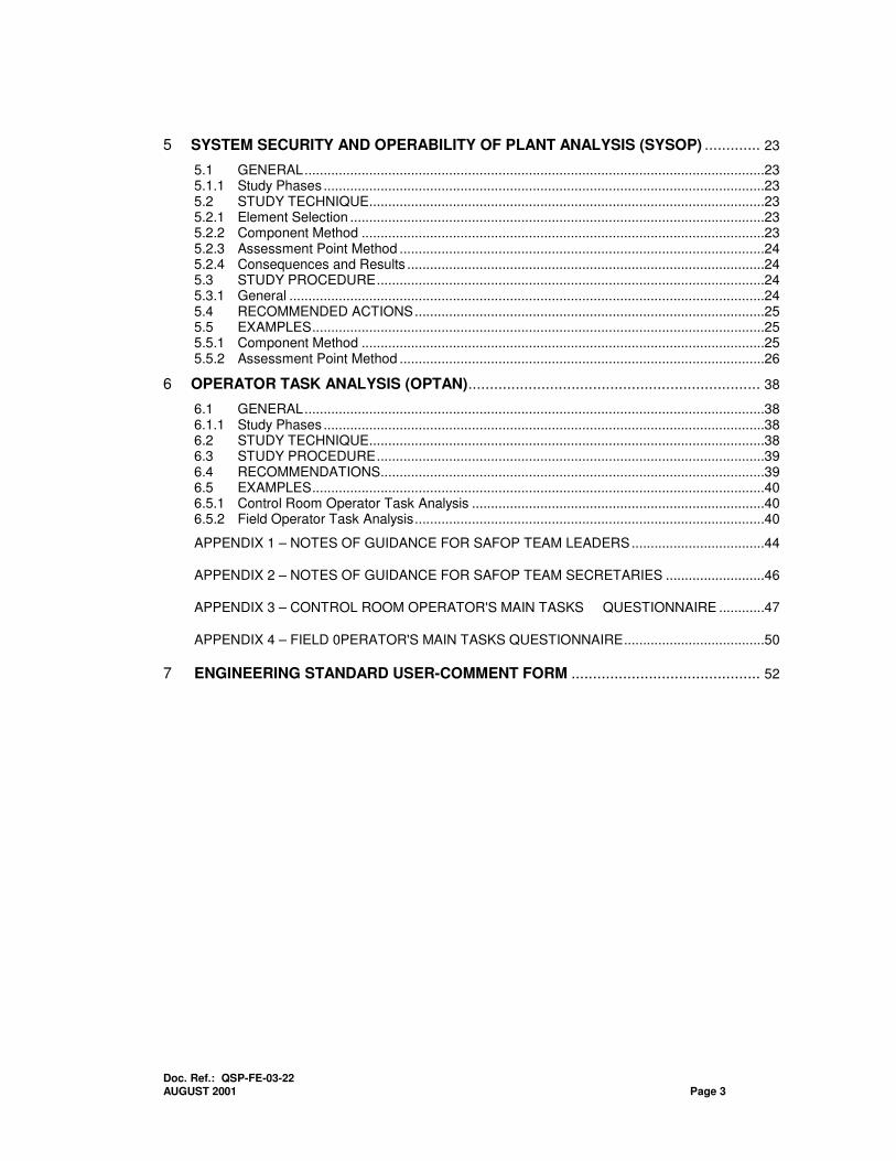
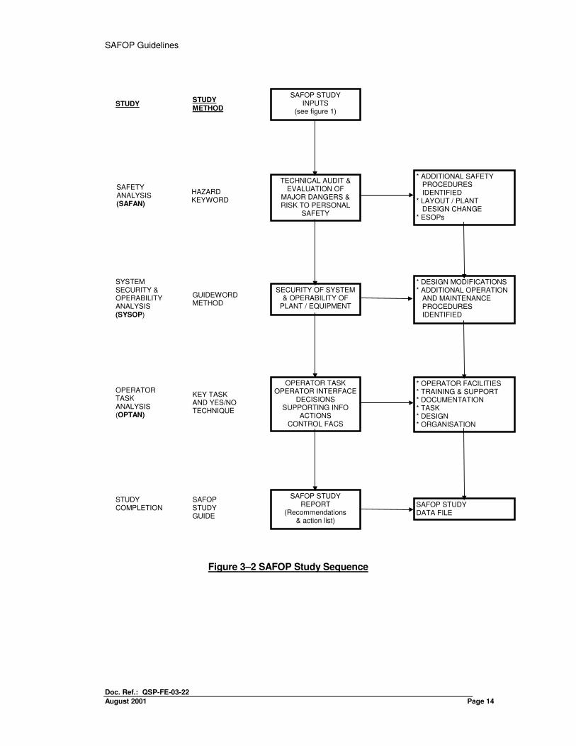
All three individual studies can be conducted independently of the other two, if necessary, but the approach shown on the flowchart (see FIGURE 3-2) should produce the best result, although it is recognised that there will be some necessary overlapping or cross-checking of individual studies. SAFAN and SYSOP studies certainly should be carried out, if possible, at both Initial and the Final phases of the project, but it is perhaps not so rewarding to carry out an OPTAN initial Study until the SYSOP Final Study is complete. Obviously it is difficult to try and identify where operator error is possible when final design of the plant and ancillary equipment is not known. However, it may help in, selecting staff who will undertake Control Room and Field Operator duties.
3.4.2 Methods
The number of team meetings should be kept to a minimum consistent with the efficient working of teams. Initial study should be completed in one to two days once team members have mastered working methods. However a final SYSOP study could well take one to three days, depending on the size of a project and the amount of major plant and ancillary equipment to be installed. Availability of team members to attend meetings must be considered but it is important not to work as a team for more than five hours at one session. This is firstly to enable the Team Secretary to write and produce copies of his worksheets for the team’s approval at the next days meeting. Secondly, so that the team remains fresh and retains its capacity for inquiring in to details of a project with the original thinking necessary to spot anomalies or detect unforeseen hazards.
3.4.3 Environment
Finally, it is desirable to conduct team meetings in an environment remote from the normal offices of the members to prevent continual interruptions and phone calls causing inevitable distraction. A Conference Room with plenty of space for laying-out drawings, etc., is ideal.
3.5 PREPARATIVE WORK
3.5.1 General
Preparative work can be classified into two elements: one consisting of data provided by Consultants and Manufacturers and the other undertaken by individual team members. Engineering design is provided by Consultants and Manufactures in the form of layout drawings, protection schematics, Operating manuals etc. SPDC Electrical Safety Rules (ESR’s), Electrical Safety Operational Procedures (ESOP’s) and HSE Standards should be made available to teams in addition to general safety instructions that refer to particular hazards.
3.5.2 Initial Study
At this phase terms of reference are composed, teams formed and base data compiled. Working procedures are clearly defined before the main study commences.
3.5.3 Final Study
Final study teams should have design drawings, diagrams and all relevant data in a 'frozen’ state. Manufacturer(s) shall be able to incorporate any changes for deviations, which are not acceptable to the SAFOP Team. Again, appropriate
Doc. Ref.: QSP-FE-03-22 AUGUST 2001 Page 13
specialists should be able to save a team valuable time by becoming familiar with these before the team's meetings.
3.6 RECORDING
3.6.1 Worksheets
A Team Secretary has the duty to ensure that record of SAFOP study results are produced and written in a consistent and understandable manner. He must ensure that recommended actions are clear and are unambiguous, as well as record the SPDC department/EPC Contractor is to discharge the actions.
Worksheets must be clearly identified and marked to indicate whether study is at the initial or final phase of a project. All drawings and diagrams examined at team meetings must be listed on appropriate Worksheets, together with revision numbers of copy tabled.
3.7 FOLLOW-UP
3.7.1 Recommended Actions
Follow-up work undertaken on completion of a SAFOP study will be in the form of recommended actions calling, for example, for modification to design or a written procedure to cater for a particular situation. If an Initial Study is undertaken, recorded Worksheets should be an invaluable aid when the Final Study is commenced. Assumptions that have sometimes to be made at an early design phase can be checked for accuracy when design drawings are in an approved 'frozen' state. Recommended actions sometimes will now not be necessary for a particular aspect as, in the meantime, the project engineer may have taken steps to improve the situation.
SAFOP Guidelines
Doc. Ref.: QSP-FE-03-22
August 2001 Page 14
Figure 3–2 SAFOP Study Sequence
SAFETY ANALYSIS (SAFAN)
STUDY STUDY METHOD
HAZARD KEYWORD
SYSTEM SECURITY & OPERABILITY ANALYSIS (SYSOP)
GUIDEWORD METHOD
OPERATOR TASK ANALYSIS (OPTAN)
KEY TASK AND YES/NO TECHNIQUE
STUDY COMPLETION
SAFOP STUDY GUIDE
TECHNICAL AUDIT & EVALUATION OF
MAJOR DANGERS & RISK TO PERSONAL
SAFETY
* ADDITIONAL SAFETY PROCEDURES IDENTIFIED * LAYOUT / PLANT DESIGN CHANGE * ESOPs
SECURITY OF SYSTEM & OPERABILITY OF
PLANT / EQUIPMENT
* DESIGN MODIFICATIONS * ADDITIONAL OPERATION AND MAINTENANCE PROCEDURES IDENTIFIED
OPERATOR TASK OPERATOR INTERFACE
DECISIONS SUPPORTING INFO
ACTIONS CONTROL FACS
SAFOP STUDY REPORT
(Recommendations & action list)
* OPERATOR FACILITIES * TRAINING & SUPPORT * DOCUMENTATION * TASK * DESIGN * ORGANISATION
SAFOP STUDY DATA FILE
SAFOP STUDY INPUTS
(see figure 1)
Doc. Ref.: QSP-FE-03-22 AUGUST 2001 Page 15
4. SAFETY ANALYSIS (SAFAN)
4.1 GENERAL
4.1.1 Study Phases
A SAFAN study may be divided into two distinct phases
• An initial technical audit undertaken by the study team on conceptual design to examine an overall project in terms of safe operation and safety of personnel, (Section 3.2 gives details.)
• A final SAFAN study carried out during the frozen design stage prior to manufacture, when construction drawings are available, giving detailed layouts of overhead lines and substations. These drawings can be examined now in detail by the study team to determine if project design permits safe operation with adequate safety of personnel.
4.2 STUDY TECHNIQUE
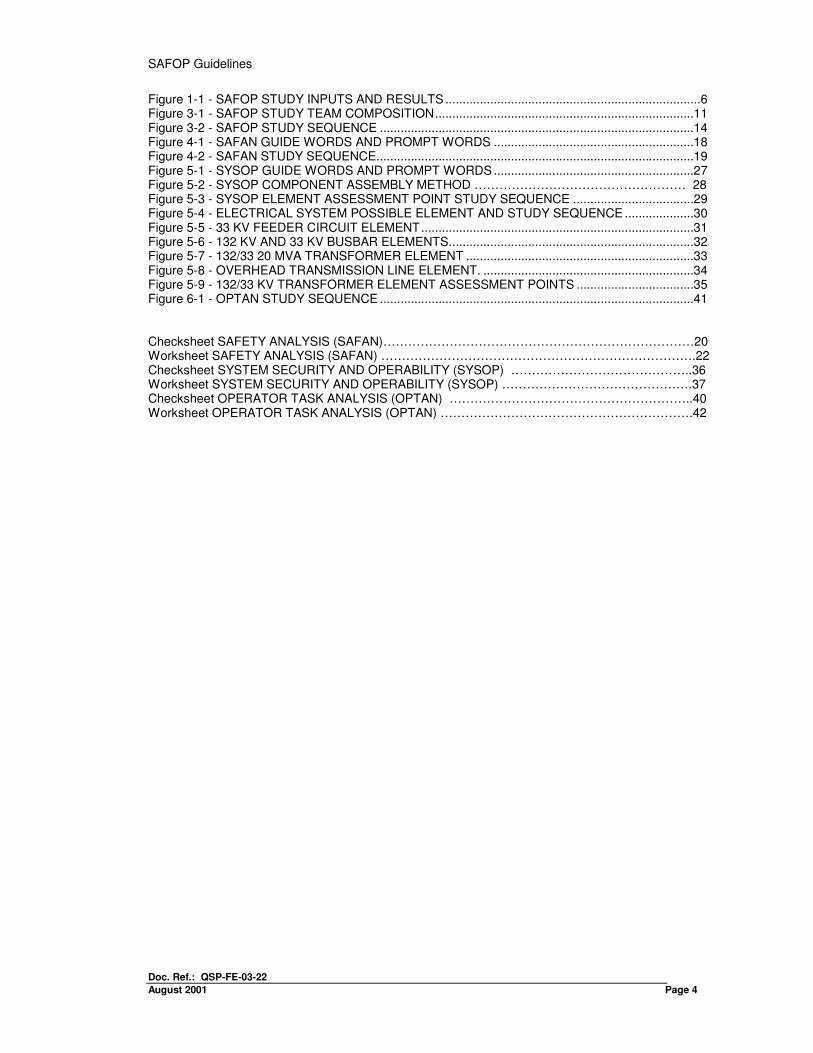
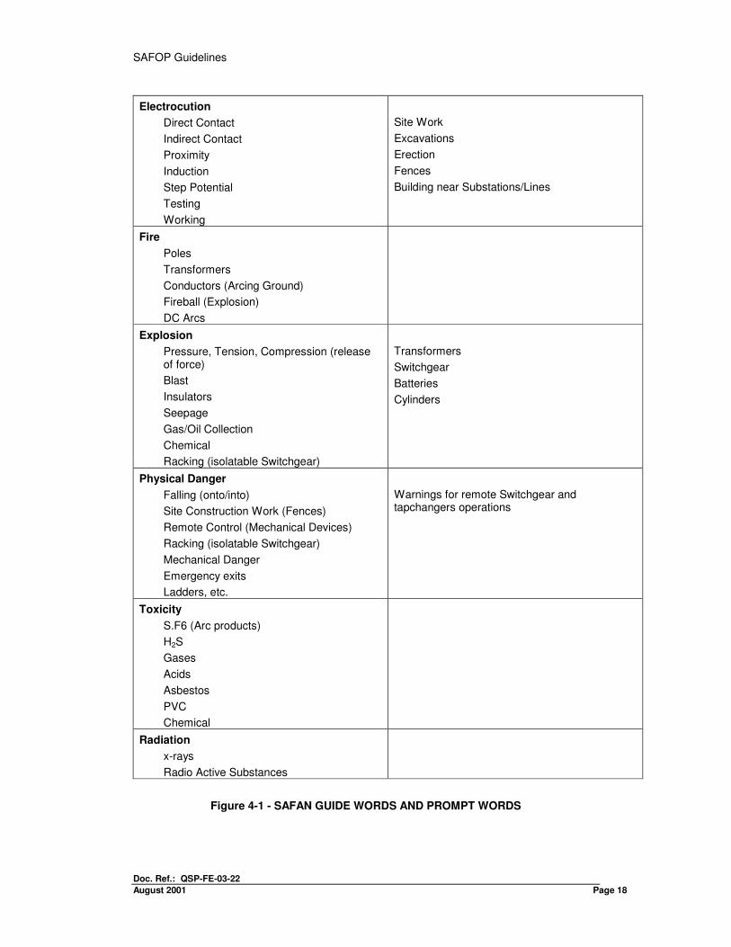
To assist the study team in identifying potential hazards, a number of 'Keywords' or ‘Guide words’ are used to identify specific types of dangers that an installation can present to various categories of personnel who may be effected by it. To further aid the team in its evaluation, a list of 'Prompt-words' for each Keyword has been prepared (see FIGURE 4-1 for suggested Key words and Prompt words). Possible dangers that an installation presents to persons vary with degree of access or exposure permitted. Within these limitations three groups of persons have been identified and classified into:
• Outside Persons' (not under SPDC Safety Regulations).
• ‘Non-Electrical SPDC Staff and Contractors’ (under SPDC Safety Regulations, but with No Authorised Entry into SPDC Electrical Installations).
• ‘Electrical SPDC Staff and Contractors' (under SPDC Safety Regulations With Entry to Electrical Installations).
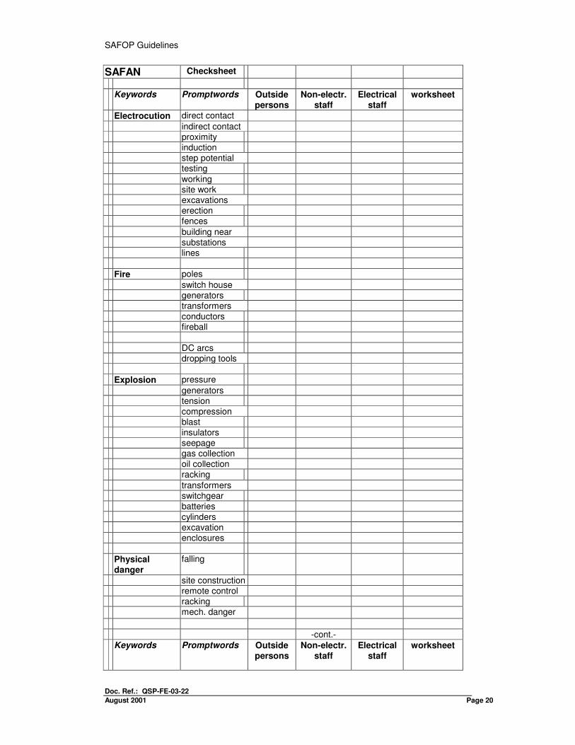
A common checksheet is used for each of the above classifications. The group being examined shall be indicated in the worksheet.
4.3 PROCEDURE
The team assesses in detail possible situations where persons may be exposed to danger. The Team Leader selects a constituent part of the overall installation for detailed study and applies a Hazard Keyword; for example, the part chosen could be a section of overhead line, with the Keyword 'Electrocution' applied. For each Hazard Keyword chosen, situations where persons may be exposed to danger be assessed in conjunction with necessary corresponding design information such as plant layout, boundary fences, screening, etc. Team discussions take place to identify all possible situations where danger to each classification of person could arise and will be indicated on the checksheet.
-cont.- It should be borne in mind that electrical installations operate as complete systems, where occurrence or initiation of faults in one location may cause serious
SAFOP Guidelines
Doc. Ref.: QSP-FE-03-22
August 2001 Page 16
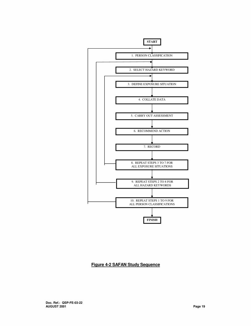
consequences elsewhere in a system. For example, a lightning strike on an overhead line may result in flashover of equipment at the nearest substation some distance from the original incident location. Electrical faults can also vary over a considerable time period, with fault duration of fractions of a second to periods of several minutes, depending on protection, alarm and control schemes and, in the last resort, on the reactions of the operators. Recognition of potential Hazards will depend, to some extent, on operational background and experience of team members. However, the Prompt-word list in FIGURE 4-1 may be used to stimulate discussion and to aid the team in its assessment. Study continues until all Hazard Keywords have been applied in turn to each individual constituent part of a complete installation and possible dangerous situations determined for each personnel classification. In a large installation it is possible that some constituent parts will recur and, if identical, will not require further investigation. However, any interactions with other parts of the installation may still need to be assessed. FIGURE 4-2 illustrates the Safety Analysis study sequence.
4.4 RECOMMENDED ACTIONS
All situations identified on the checksheet as being potentially dangerous to personnel are recorded on SAFAN Worksheets, together with information used or required for assessment and, if possible, with actions recommended by the Study Team. These recommendations should, if possible, suggest means by which:
• The causes of the Hazard are removed.
• Failing this the means to prevent persons being exposed to the Hazard.
• Finally if these cannot be satisfactorily achieved, then the minimum response is to limit consequences of the Hazard as far as practicable.
In the case of minimum response to a defined hazard, an additional decision needs to be reached as to whether further research or investigation is required to remove or mitigate the Hazard, the SPDC department/EPC Contractor responsible is recorded on the Worksheet by the Team Secretary.
4.5 EXAMPLES
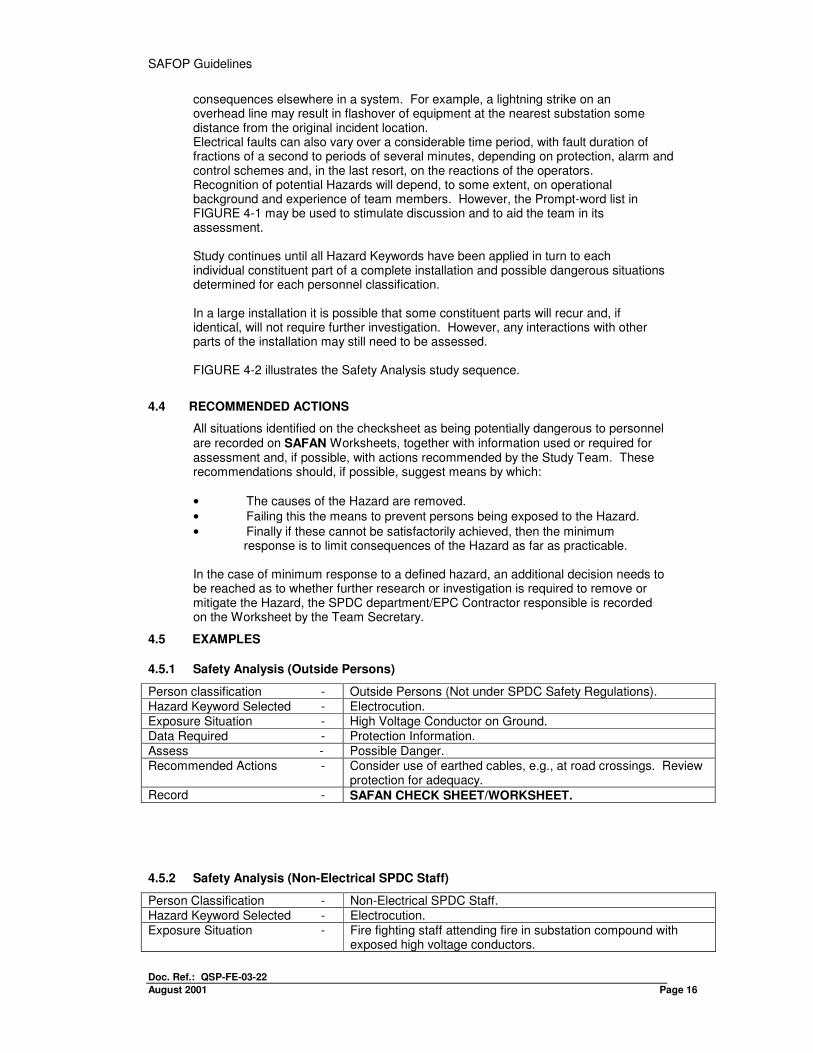
4.5.1 Safety Analysis (Outside Persons)
Person classification - Outside Persons (Not under SPDC Safety Regulations). Hazard Keyword Selected - Electrocution. Exposure Situation - High Voltage Conductor on Ground. Data Required - Protection Information. Assess - Possible Danger. Recommended Actions - Consider use of earthed cables, e.g., at road crossings. Review
protection for adequacy. Record - SAFAN CHECK SHEET/WORKSHEET.
4.5.2 Safety Analysis (Non-Electrical SPDC Staff)
Person Classification - Non-Electrical SPDC Staff. Hazard Keyword Selected - Electrocution. Exposure Situation - Fire fighting staff attending fire in substation compound with
exposed high voltage conductors.
Doc. Ref.: QSP-FE-03-22 AUGUST 2001 Page 17
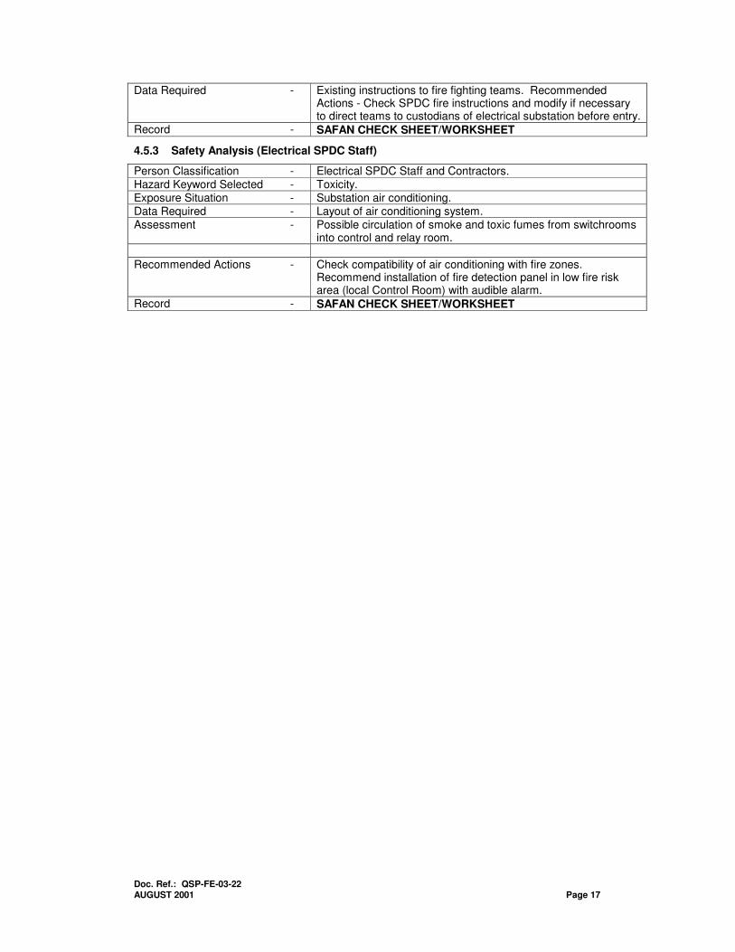
Data Required - Existing instructions to fire fighting teams. Recommended Actions - Check SPDC fire instructions and modify if necessary to direct teams to custodians of electrical substation before entry.
Record - SAFAN CHECK SHEET/WORKSHEET
4.5.3 Safety Analysis (Electrical SPDC Staff)
Person Classification - Electrical SPDC Staff and Contractors. Hazard Keyword Selected - Toxicity. Exposure Situation - Substation air conditioning. Data Required - Layout of air conditioning system. Assessment - Possible circulation of smoke and toxic fumes from switchrooms
into control and relay room. Recommended Actions - Check compatibility of air conditioning with fire zones.
Recommend installation of fire detection panel in low fire risk area (local Control Room) with audible alarm.
Record - SAFAN CHECK SHEET/WORKSHEET
SAFOP Guidelines
Doc. Ref.: QSP-FE-03-22
August 2001 Page 18
Electrocution
Direct Contact
Indirect Contact
Proximity
Induction
Step Potential
Testing
Working
Site Work
Excavations
Erection
Fences
Building near Substations/Lines
Fire
Poles
Transformers
Conductors (Arcing Ground)
Fireball (Explosion)
DC Arcs
Explosion
Pressure, Tension, Compression (release of force)
Blast
Insulators
Seepage
Gas/Oil Collection
Chemical
Racking (isolatable Switchgear)
Transformers
Switchgear
Batteries
Cylinders
Physical Danger
Falling (onto/into)
Site Construction Work (Fences)
Remote Control (Mechanical Devices)
Racking (isolatable Switchgear)
Mechanical Danger
Emergency exits
Ladders, etc.
Warnings for remote Switchgear and tapchangers operations
Toxicity
S.F6 (Arc products)
H2S
Gases
Acids
Asbestos
PVC
Chemical
Radiation
x-rays
Radio Active Substances
Figure 4-1 - SAFAN GUIDE WORDS AND PROMPT WORDS
Doc. Ref.: QSP-FE-03-22 AUGUST 2001 Page 19
Figure 4-2 SAFAN Study Sequence
1. PERSON CLASSIFICATION
2. SELECT HAZARD KEYWORD
3. DEFINE EXPOSURE SITUATION
4. COLLATE DATA
5. CARRY OUT ASSESSMENT
6. RECOMMEND ACTION
7. RECORD
8. REPEAT STEPS 3 TO 7 FOR
ALL EXPOSURE SITUATIONS
9. REPEAT STEPS 2 TO 8 FOR
ALL HAZARD KEYWORDS
10. REPEAT STEPS 1 TO 9 FOR
ALL PERSON CLASSIFICATIONS
START
FINISH
SAFOP Guidelines
Doc. Ref.: QSP-FE-03-22
August 2001 Page 20
SAFAN Checksheet
Keywords Promptwords Outside persons
Non-electr. staff
Electrical staff
worksheet
Electrocution direct contact
indirect contact proximity induction step potential testing
working site work excavations erection fences
building near substations lines Fire poles
switch house generators transformers conductors fireball
DC arcs dropping tools Explosion pressure
generators tension compression blast insulators seepage gas collection oil collection racking
transformers switchgear batteries
cylinders excavation enclosures Physical
danger
falling
site construction remote control racking mech. danger
-cont.-
Keywords Promptwords Outside persons
Non-electr. staff
Electrical staff
worksheet
Doc. Ref.: QSP-FE-03-22 AUGUST 2001 Page 21
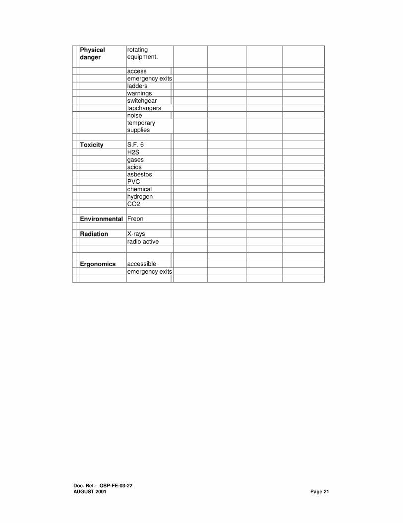
Physical danger
rotating equipment.
access emergency exits
ladders warnings switchgear tapchangers noise temporary
supplies
Toxicity S.F. 6
H2S gases acids asbestos PVC chemical hydrogen
CO2 Environmental Freon
Radiation X-rays
radio active
Ergonomics accessible
emergency exits
SAFOP Guidelines
Doc. Ref.: QSP-FE-03-22
August 2001 Page 22
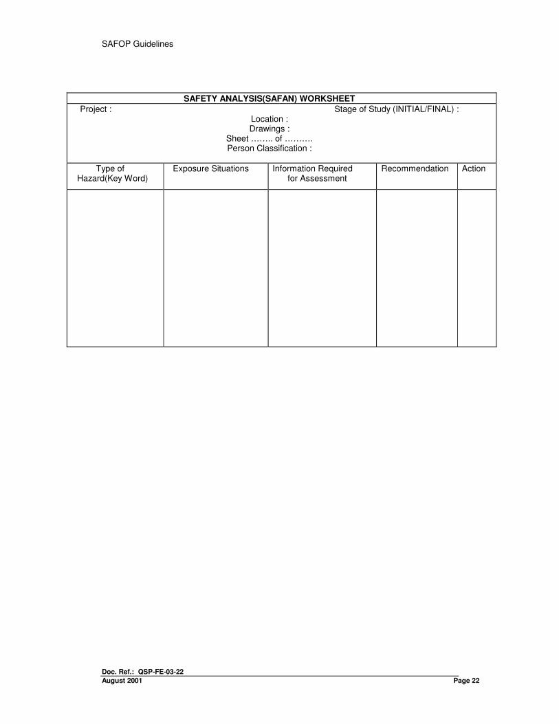
SAFETY ANALYSIS(SAFAN) WORKSHEET
Project : Stage of Study (INITIAL/FINAL) : Location : Drawings :
Sheet …….. of ………. Person Classification :
Type of Hazard(Key Word)
Exposure Situations Information Required for Assessment
Recommendation Action
SAFOP Guidelines
Doc. Ref.: QSP-FE-03-22
August 2001 Page 23
5 SYSTEM SECURITY AND OPERABILITY OF PLANT ANALYSIS (SYSOP)
5.1 GENERAL
5.1.1 Study Phases
A SYSOP study may be undertaken in two distinct phases. They are:
•An initial study should be conducted out on the conceptual design to help clarify the objectives of the project in terms of overall system security and operability. (Section 2.2 gives details).
• A final study should be conducted at the 'frozen' design stage to study in detail the security and operability of a system, its plant and equipment.
5.2 STUDY TECHNIQUE
5.2.1 Element Selection
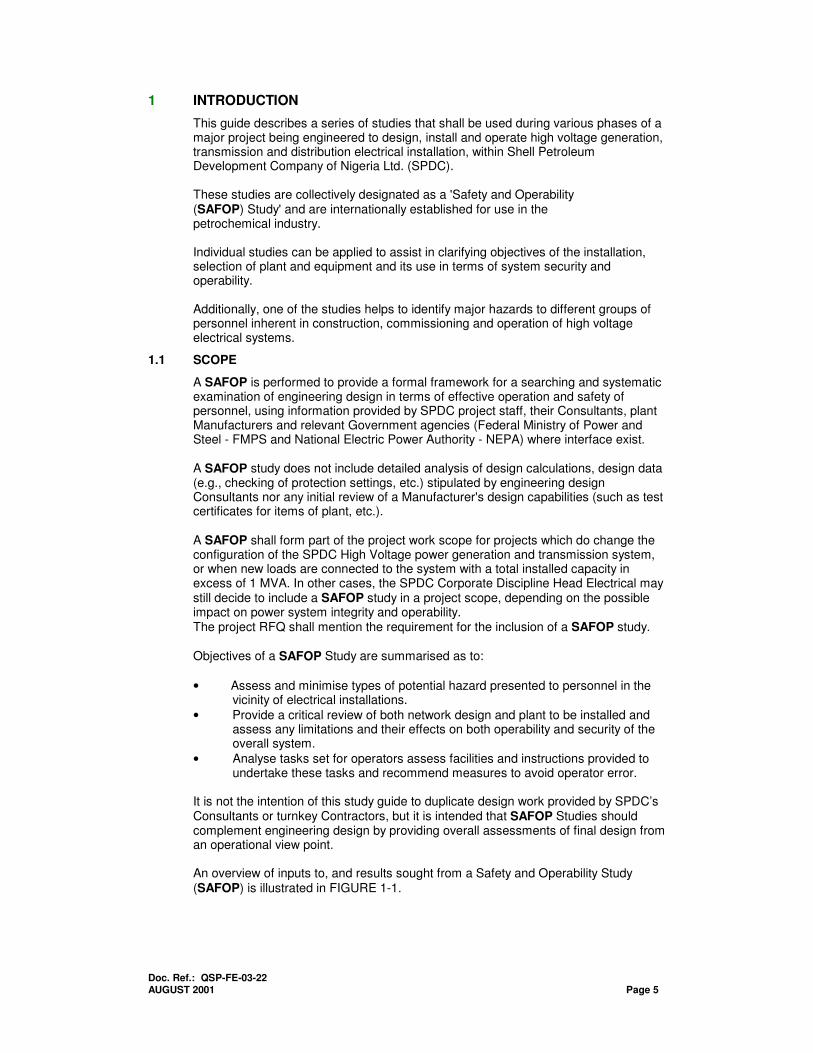
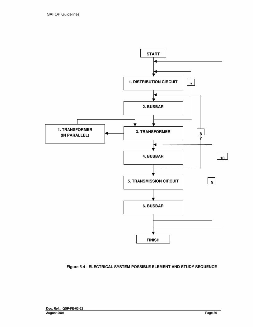
This stage of study systematically questions engineering design and operation of a project to identify possible limitations and lack of flexibility, with their consequences to operability and security to a system. Detailed examination of large, complex projects is facilitated by breaking-down projects into a number of discrete Elements for detailed examination. Elements should be small enough to be manageable and large enough to be of interest in terms of study objectives and, if possible, be a whole subsystem or unit of a complete system. A system under study should be carefully examined to determine which parts to select as basic Elements. These could be based on Isolation Points for major items of plant, or upon associated Protection or Operational Zones. Suggested Elements selected from an electrical system be given in FIGURES 5-4, 5-5, 5-6 and 5-8. FIGURE 5-2 illustrates the SYSOP study sequence for Element assessment. It is possible that an assessed Element will recur many times throughout a complete system and, if identical, will not require further assessment. However, interaction of individual Elements with each other may have to be assessed. For e.g., two transformers in parallel or encroachment of busbar protection into adjacent Elements. The flowchart in FIGURE 5-3 illustrates this principle.
5.2.2 Component Method
A Guide-word technique is used which is similar to that used in SAFAN studies but with basic Guide-words chosen to emphasise operation and security content of a study. Guidewords assist a study team in questioning every part of a project design and operation in a manner that ensures systematic examination for deviations affecting security and operability of system plant and equipment.
-cont.- This method of assessment requires the selected Element to be broken down into a number of components for detailed examination, each Component being a discrete major item of plant or support system.
SAFOP Guidelines
Doc. Ref.: QSP-FE-03-22
August 2001 Page 24
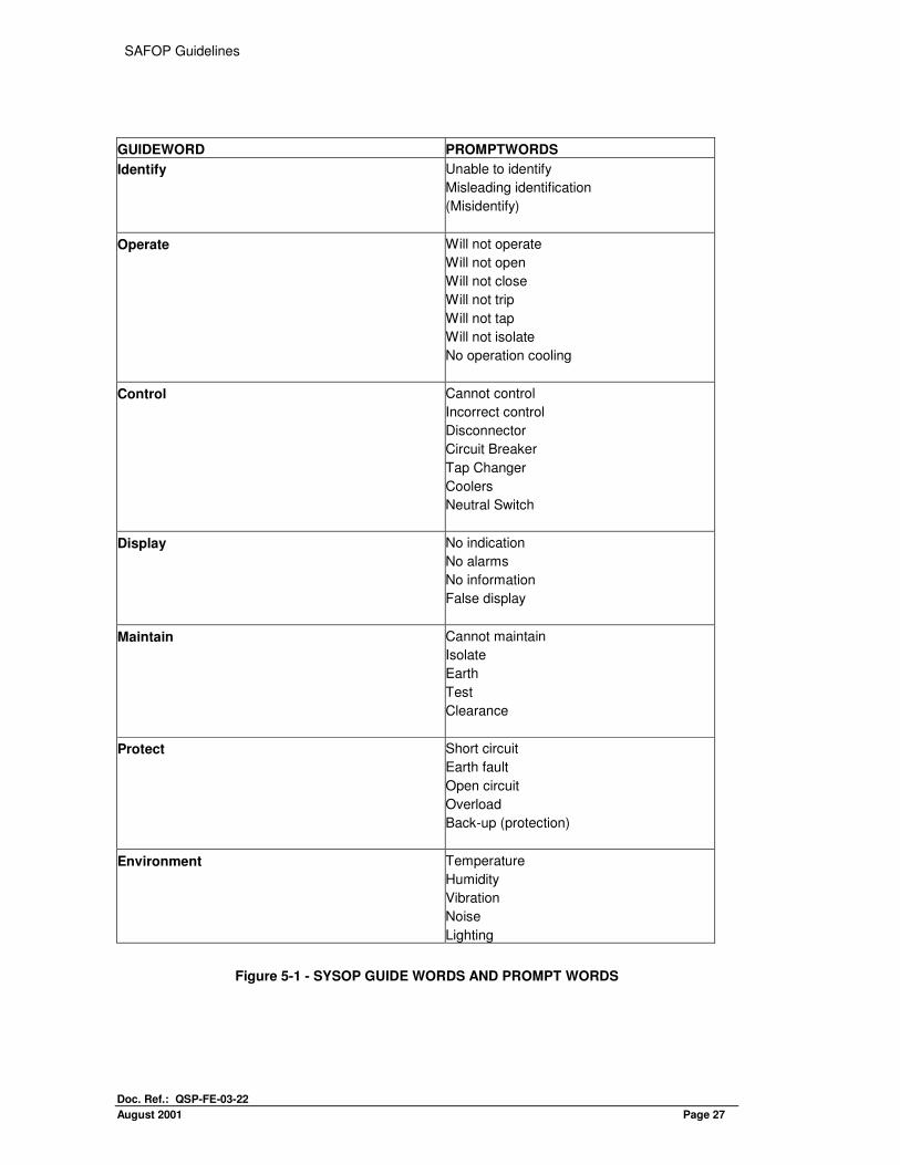
Identical Components need be assessed only once, although their relationship with other Components in the Element may need to be separately assessed. To help a team to identify possible deviations, FIGURE 5-1 lists Guidewords with associated prompt-words that can be used to fill in the checksheet. The flowchart FIGURE 5-2 illustrates the Component method study sequence.
5.2.3 Assessment Point Method
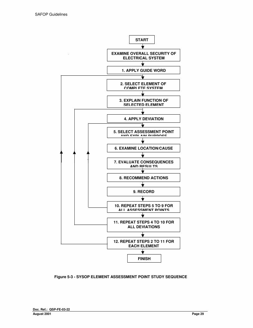
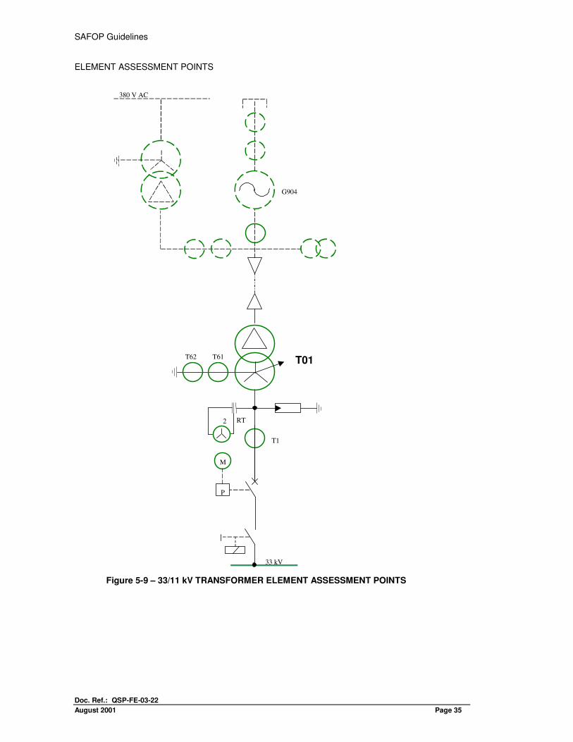
The Guideword 'Protect' requires a different technique as it assesses the consequences of applying a known deviation, such as a conductor earth fault or a system overload to various locations within an Element. Locations known as 'Assessment Points' have their positions defined by numbering interconnections between components within an Element. (See FIGURE 5-9). A list of prompt-words associated with the Guideword 'Protect' is given in FIGURE 4-1. Flowchart FIGURE 5-3 illustrates the Element Assessment Point method study sequence.
5.2.4 Consequences and Results
Consequences and results obtained from SYSOP studies are recorded on SYSOP worksheets.
5.3 STUDY PROCEDURE
5.3.1 General
A large schematic diagram of an Electrical System under study should be displayed and its general intention explained with regard to overall security and operation. Then the basic Elements of the system are defined, while identical Elements, Components and Assessment Points are identified and marked on the system diagram. The relationship of the Elements to each other and to the complete system, the various combinations required to assess these relationships etc. should be noted and a list prepared. The order in which Elements are chosen for review should proceed in a logical manner starting with a relatively simple Element, at the distribution end of a system, and then up through the higher voltages. The first Element should be selected for systematic critical review; its function explained and Components/Assessment Points within defined, with explanations given of their function and purpose. The Study Team Leader then selects a Component from within the Element and applies the first Guideword. The team discusses possible deviations arising from application of the Guideword with prompt words to the Component. At this early stage in the proceedings, and with an inexperienced team, it may be necessary to use Prompt-words to stimulate discussion. In the case of the Component and Guideword cited above, Prompt-words 'will not close' or 'will not trip' could be used.
-cont.-
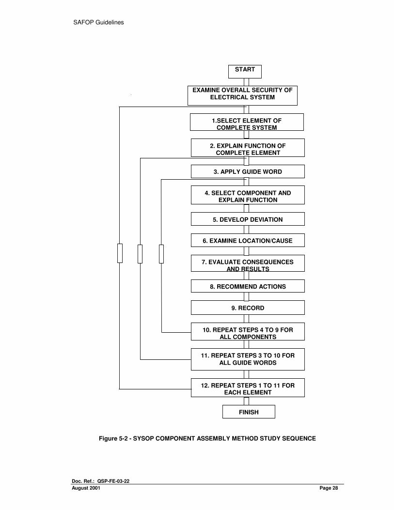
As Deviations are detected, the Team Leader should ensure that all team members understand causes, consequences and results arising from deviations. If a solution cannot be found at the team meeting, deviations should be noted for future investigation. Flowchart FIGURE 5-2 illustrates the study sequence for the Component Assessment method.
SAFOP Guidelines
Doc. Ref.: QSP-FE-03-22
August 2001 Page 25
Using Assessment point method in conjunction with the Guideword 'Protect', the team now assesses in detail consequences and results arising from abnormalities in normal running of a system. Deviations are applied in turn at chosen locations throughout the Element. For each location the team evaluates all possible consequences and their resultant effects both within and beyond Element boundaries. Results of this appraisal are recorded, together with the team’s recommendations, on a SYSOP Worksheet. The study continues until all relevant deviations have been applied to pertinent locations for each selected Element of a complete system.
5.4 RECOMMENDED ACTIONS
The study continues until all relevant Guidewords have been applied to each Component/Assessment Point within the Elements and all Elements have been examined in their relationship to each other and to the complete system. All significant Deviations and Consequences are recorded, together with their location and cause, and where possible remedial actions are recommended by the study tears, together with the responsible SPDC department.
5.5 EXAMPLES
5.5.1 Component Method
Selected Element - 132/33 kV Transformer. Element Function - To supply power and regulate voltage. Guideword applied - Operate. Selected Component - Transformer. Prompt-word - No operation. Deviation Developed - Forced cooling fails to operate. Location and Cause - Loss of cooler supply. Consequence and Result - Loss of supply as 33kV circuit breaker
opens to off- load transformer. Recommended Action - Fit cooler failure alarms; check cyclic rating
of transformer. Record - SYSOP Checksheet/Worksheet
5.5.2 Assessment Point Method
Apply Guide-word - 'Protect' Selected Element - 132/33kV Transformer Element Function - To supply power and regulate voltage Deviation Applied - Short circuit and/or earth fault. Assessment Point - Located between 132 kV circuit breaker and it’s associated current transformers. Purpose - To check protection zones of operations. Location and Cause - Outage extends to 132 kV Busbar zone protection.

SAFOP Guidelines
Doc. Ref.: QSP-FE-03-22
August 2001 Page 26
Consequences and Results- Busbar zone protection isolates adjacent 132 kV Busbar. - Loss of 132 kV interconnection - Loss of supply, only one transformer installed at substation Prompt-word - 'Back-up’ Recommended Action - Check that overhead line protection acts as back up in case
of bus-zone protection failure. Record - SYSOP Checksheet/Worksheet.
SAFOP Guidelines
Doc. Ref.: QSP-FE-03-22
August 2001 Page 27
GUIDEWORD PROMPTWORDS
Identify Unable to identify
Misleading identification
(Misidentify)
Operate Will not operate
Will not open
Will not close
Will not trip
Will not tap
Will not isolate
No operation cooling
Control
Cannot control
Incorrect control
Disconnector
Circuit Breaker
Tap Changer
Coolers
Neutral Switch
Display No indication
No alarms
No information
False display
Maintain Cannot maintain
Isolate
Earth
Test
Clearance
Protect Short circuit
Earth fault
Open circuit
Overload
Back-up (protection)
Environment
Temperature
Humidity
Vibration
Noise
Lighting
Figure 5-1 - SYSOP GUIDE WORDS AND PROMPT WORDS
SAFOP Guidelines
Doc. Ref.: QSP-FE-03-22
August 2001 Page 28
Figure 5-2 - SYSOP COMPONENT ASSEMBLY METHOD STUDY SEQUENCE
2. EXPLAIN FUNCTION OF COMPLETE ELEMENT
3. APPLY GUIDE WORD
5. DEVELOP DEVIATION
6. EXAMINE LOCATION/CAUSE
7. EVALUATE CONSEQUENCES AND RESULTS
8. RECOMMEND ACTIONS
9. RECORD
10. REPEAT STEPS 4 TO 9 FOR ALL COMPONENTS
11. REPEAT STEPS 3 TO 10 FOR
ALL GUIDE WORDS
12. REPEAT STEPS 1 TO 11 FOR EACH ELEMENT
FINISH
1.SELECT ELEMENT OF COMPLETE SYSTEM
4. SELECT COMPONENT AND EXPLAIN FUNCTION
START
EXAMINE OVERALL SECURITY OF ELECTRICAL SYSTEM
SAFOP Guidelines
Doc. Ref.: QSP-FE-03-22
August 2001 Page 29
START
2. SELECT ELEMENT OFCOMPLETE SYSTEM
3. EXPLAIN FUNCTION OFSELECTED ELEMENT
5. SELECT ASSESSMENT POINTAND EXPLAIN PURPOSE
6. EXAMINE LOCATION/CAUSE
7. EVALUATE CONSEQUENCESAND RESULTS
8. RECOMMEND ACTIONS
9. RECORD
10. REPEAT STEPS 5 TO 9 FORALL ASSESSMENT POINTS
11. REPEAT STEPS 4 TO 10 FOR
ALL DEVIATIONS
12. REPEAT STEPS 2 TO 11 FOREACH ELEMENT
FINISH
EXAMINE OVERALL SECURITY OFELECTRICAL SYSTEM
4. APPLY DEVIATION
1. APPLY GUIDE WORD
Figure 5-3 - SYSOP ELEMENT ASSESSMENT POINT STUDY SEQUENCE
SAFOP Guidelines
Doc. Ref.: QSP-FE-03-22
August 2001 Page 30
Figure 5-4 - ELECTRICAL SYSTEM POSSIBLE ELEMENT AND STUDY SEQUENCE
START
FINISH
1. DISTRIBUTION CIRCUIT
2. BUSBAR
3. TRANSFORMER
4. BUSBAR
5. TRANSMISSION CIRCUIT
6. BUSBAR
1. TRANSFORMER
(IN PARALLEL)
10
9
87
7
SAFOP Guidelines
Doc. Ref.: QSP-FE-03-22
August 2001 Page 31
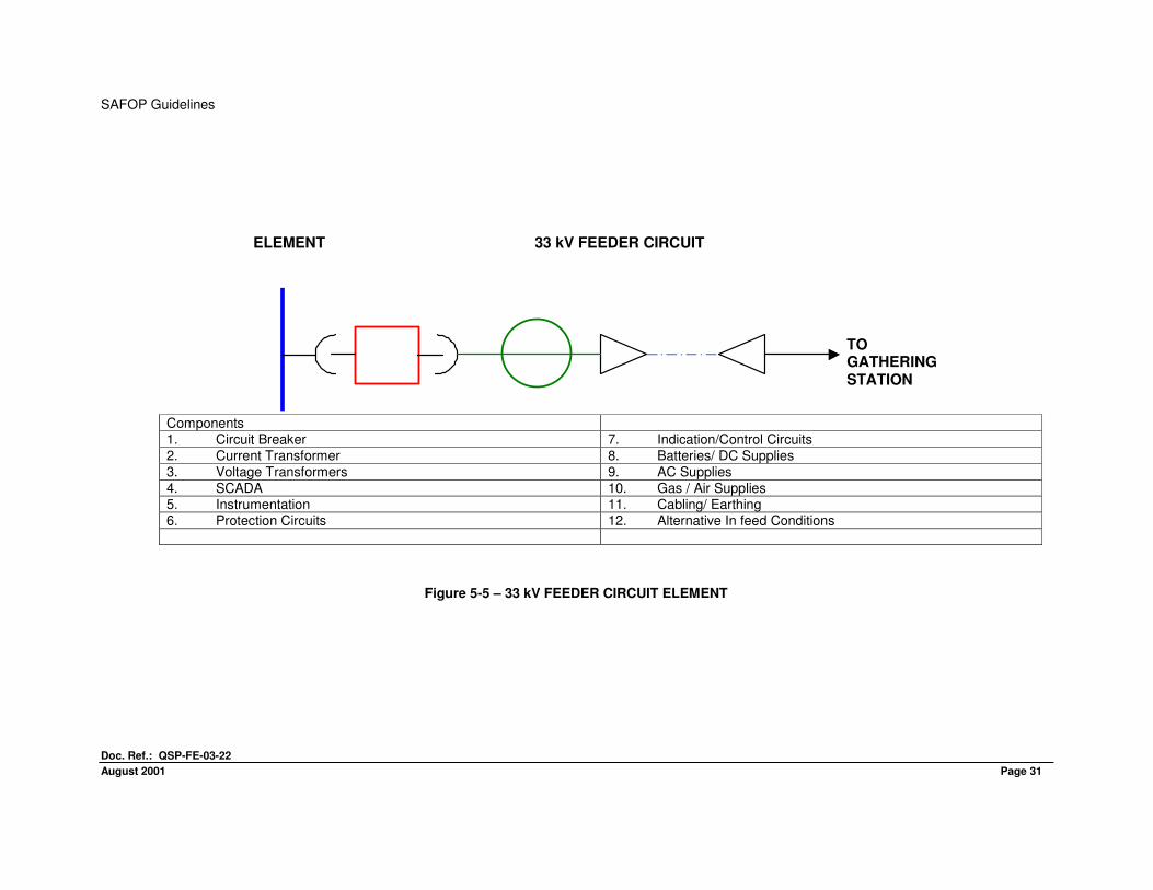
Components 1. Circuit Breaker 7. Indication/Control Circuits
2. Current Transformer 8. Batteries/ DC Supplies 3. Voltage Transformers 9. AC Supplies 4. SCADA 10. Gas / Air Supplies 5. Instrumentation 11. Cabling/ Earthing 6. Protection Circuits 12. Alternative In feed Conditions
Figure 5-5 – 33 kV FEEDER CIRCUIT ELEMENT
TOGATHERINGSTATION
ELEMENT 33 kV FEEDER CIRCUIT
SAFOP Guidelines
Doc. Ref.: QSP-FE-03-22
August 2001 page 36 Page 32
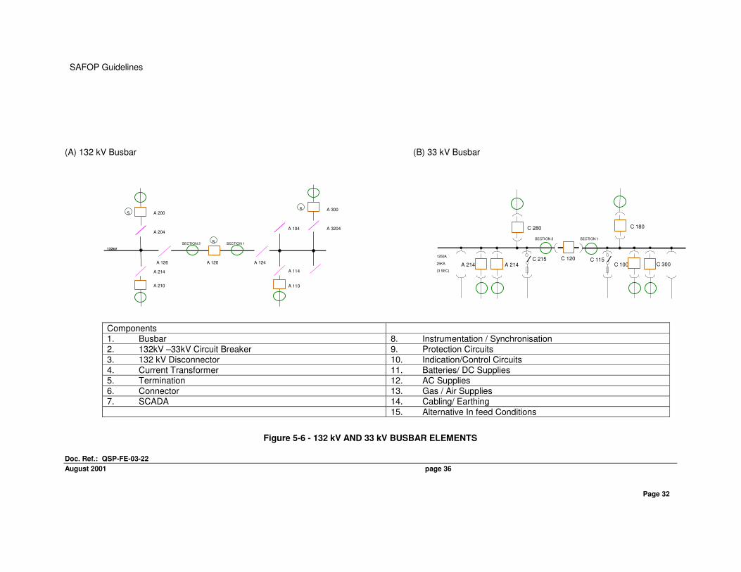
(A) 132 kV Busbar (B) 33 kV Busbar
Components 1. Busbar 8. Instrumentation / Synchronisation
2. 132kV –33kV Circuit Breaker 9. Protection Circuits 3. 132 kV Disconnector 10. Indication/Control Circuits 4. Current Transformer 11. Batteries/ DC Supplies 5. Termination 12. AC Supplies 6. Connector 13. Gas / Air Supplies 7. SCADA 14. Cabling/ Earthing
15. Alternative In feed Conditions
Figure 5-6 - 132 kV AND 33 kV BUSBAR ELEMENTS
SECTION 2 SECTION 1
A 214
1250A
25KA
(3 SEC)
A 214
C 280
C 215 C 120 C 115C 300C 100
C 180
A 200
A 204
SECTION 2 SECTION 1
A 120
S
A 210
A 300
A 3204
A 214
A 110
A 114
A 104
A 124A 126
SS
132kV
SAFOP Guidelines
Doc. Ref.: QSP-FE-03-22
August 2001 Page 33
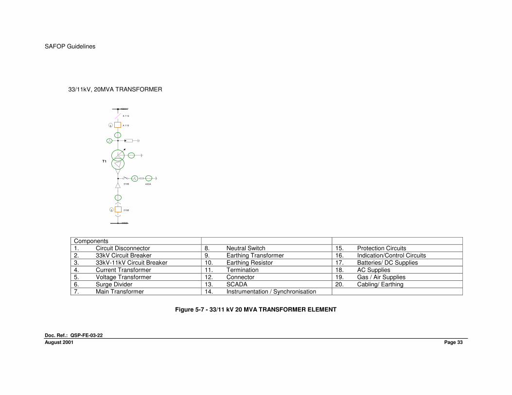
33/11kV, 20MVA TRANSFORMER
Components 1. Circuit Disconnector 8. Neutral Switch 15. Protection Circuits 2. 33kV Circuit Breaker 9. Earthing Transformer 16. Indication/Control Circuits 3. 33kV-11kV Circuit Breaker 10. Earthing Resistor 17. Batteries/ DC Supplies
4. Current Transformer 11. Termination 18. AC Supplies 5. Voltage Transformer 12. Connector 19. Gas / Air Supplies 6. Surge Divider 13. SCADA 20. Cabling/ Earthing 7. Main Transformer 14. Instrumentation / Synchronisation
Figure 5-7 - 33/11 kV 20 MVA TRANSFORMER ELEMENT
A 110
A 114
11kV
T1
0185 400A
0180
S
S
133 kV
SAFOP Guidelines
Doc. Ref.: QSP-FE-03-22
August 2001 page 36 Page 34
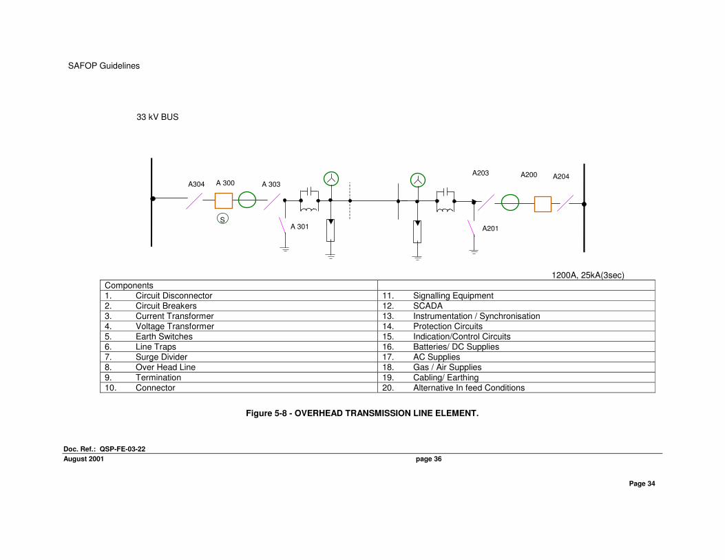
33 kV BUS
1200A, 25kA(3sec)
Components 1. Circuit Disconnector 11. Signalling Equipment 2. Circuit Breakers 12. SCADA 3. Current Transformer 13. Instrumentation / Synchronisation 4. Voltage Transformer 14. Protection Circuits 5. Earth Switches 15. Indication/Control Circuits 6. Line Traps 16. Batteries/ DC Supplies 7. Surge Divider 17. AC Supplies 8. Over Head Line 18. Gas / Air Supplies
9. Termination 19. Cabling/ Earthing 10. Connector 20. Alternative In feed Conditions
Figure 5-8 - OVERHEAD TRANSMISSION LINE ELEMENT.
A 300A304
S
A 303
A 301 A201
A203 A200 A204
SAFOP Guidelines
Doc. Ref.: QSP-FE-03-22
August 2001 Page 35
ELEMENT ASSESSMENT POINTS
Figure 5-9 – 33/11 kV TRANSFORMER ELEMENT ASSESSMENT POINTS
T01
T1
P
M
T62 T61
2 RT
33 kV
G904
380 V AC
SAFOP Guidelines
Doc. Ref.: QSP-FE-03-22
August 2001 page 36
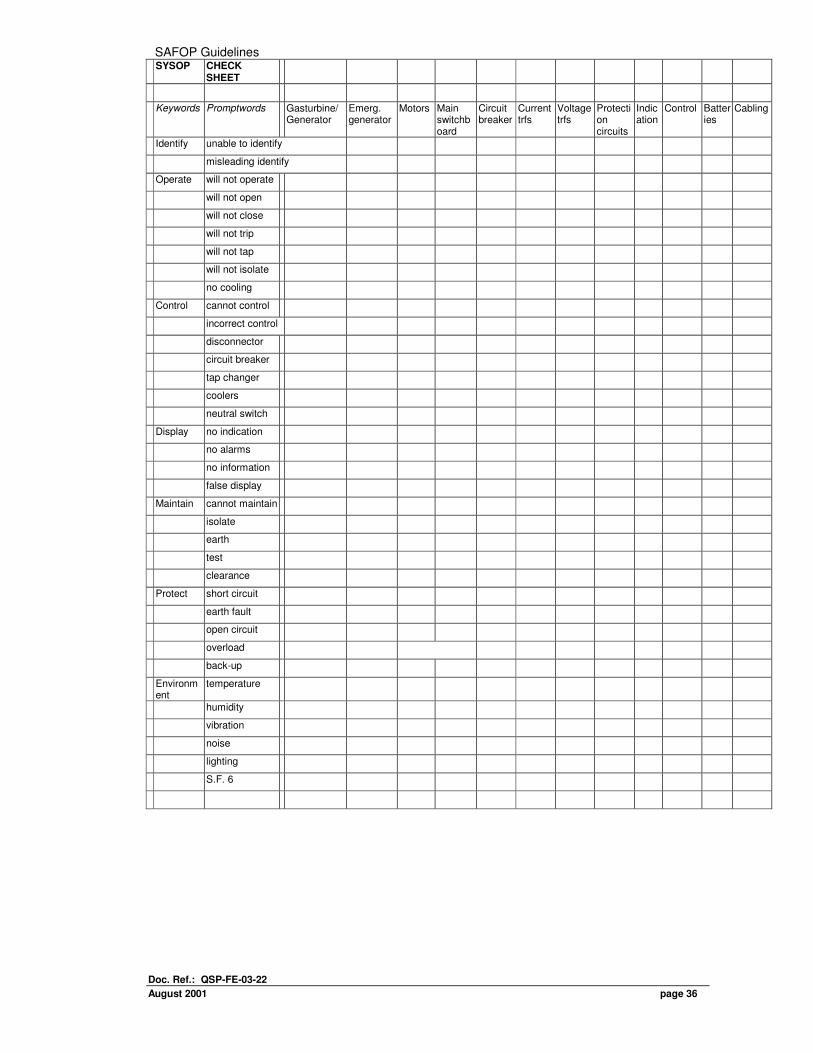
SYSOP CHECK SHEET
Keywords Promptwords Gasturbine/ Generator
Emerg. generator
Motors Main switchboard
Circuit breaker
Current trfs
Voltage trfs
Protection circuits
Indication
Control Batteries
Cabling
Identify unable to identify
misleading identify
Operate will not operate
will not open
will not close
will not trip
will not tap
will not isolate
no cooling
Control cannot control
incorrect control
disconnector
circuit breaker
tap changer
coolers
neutral switch
Display no indication
no alarms
no information
false display
Maintain cannot maintain
isolate
earth
test
clearance
Protect short circuit
earth fault
open circuit
overload
back-up
Environment
temperature
humidity
vibration
noise
lighting
S.F. 6
SAFOP Guidelines
Doc. Ref.: QSP-FE-03-22
August 2001 Page 37
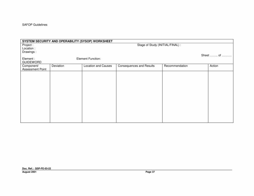
SYSTEM SECURITY AND OPERABILITY (SYSOP) WORKSHEET
Project : Stage of Study (INITIAL/FINAL) : Location : Drawings :
Sheet …….. of ………. Element : Element Function: GUIDEWORD
Component/ Assessment Point
Deviation Location and Causes Consequences and Results Recommendation Action
SAFOP Guidelines
Doc. Ref.: QSP-FE-03-22
August 2001 Page 38
6 OPERATOR TASK ANALYSIS (OPTAN)
6.1 GENERAL
6.1.1 Study Phases
An OPTAN study may be divided into two distinct phases. They are:
• The initial study may be carried out after the conceptual design stage. However, as specific data will not be available at this time, study should concentrate on the system requirements and staffing for Control Room and Field Operator duties. (Subsection 3.2.1 gives details.)
• The final study should take place following SAFAN and SYSOP studies on the 'frozen' design when many Operator tasks will have been identified.
The study team should look in detail at tasks required to be undertaken by Control Room and Field Operators, analyse Operator predicted response to these tasks, and review equipment and instructions provided.
6.2 STUDY TECHNIQUE
OPTAN methods used by the SAFOP Study Team naturally follow on from SAFAN techniques and SYSOP examination sessions. (Chapters 4.0 and 5.0 of this Engineering Guideline.) Detailed complexity of all Operator actions and decisions makes it unlikely that a complete assessment of every eventuality will be achieved. However, by drawing attention to certain salient points and general problems, possibility of human error should be considerably reduced. Anything which makes human operator’s work more difficult can lead to mistakes. Operators may develop poor work habits to cope with difficulties. This may lead them to either forget to do something, or to use wrong working methods. These habits may be tolerated under normal working conditions but are likely to give rise to serious problems when combined with power plant failure or loss of supply. Major incidents usually occur through combination of minor failures. For example, one item (such as a VDU display, which is difficult to read) may seem trivial when considered alone, but when considered with other factors (such as heavy workload) may have serious consequences. To assist the team in its study, Operator tasks in both Control Room and Field are subdivided under three main headings. These are:
• Normal Operator Duties.
• System Switching.
• Abnormal or Emergency Conditions.
Each of these duties are further subdivided under headings which attempt to establish a correlation between procedures envisaged and situations considered. These headings, defined as key tasks, are:
• Monitor/Check.
• Make Decisions.
• Actions.
Typical questionnaires to establish main tasks for Control Room and Field Operators are provided in APPENDICES 3 and 4.
SAFOP Guidelines
Doc. Ref.: QSP-FE-03-22
August 2001 Page 39
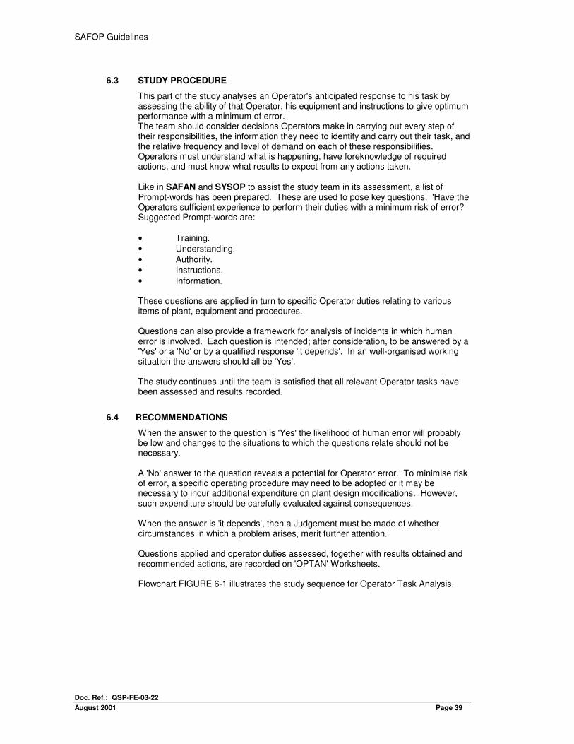
6.3 STUDY PROCEDURE
This part of the study analyses an Operator's anticipated response to his task by assessing the ability of that Operator, his equipment and instructions to give optimum performance with a minimum of error. The team should consider decisions Operators make in carrying out every step of their responsibilities, the information they need to identify and carry out their task, and the relative frequency and level of demand on each of these responsibilities. Operators must understand what is happening, have foreknowledge of required actions, and must know what results to expect from any actions taken. Like in SAFAN and SYSOP to assist the study team in its assessment, a list of Prompt-words has been prepared. These are used to pose key questions. 'Have the Operators sufficient experience to perform their duties with a minimum risk of error? Suggested Prompt-words are:
• Training.
• Understanding.
• Authority.
• Instructions.
• Information. These questions are applied in turn to specific Operator duties relating to various items of plant, equipment and procedures. Questions can also provide a framework for analysis of incidents in which human error is involved. Each question is intended; after consideration, to be answered by a 'Yes' or a 'No' or by a qualified response 'it depends'. In an well-organised working situation the answers should all be 'Yes'. The study continues until the team is satisfied that all relevant Operator tasks have been assessed and results recorded.
6.4 RECOMMENDATIONS
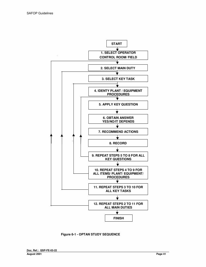
When the answer to the question is 'Yes' the likelihood of human error will probably be low and changes to the situations to which the questions relate should not be necessary. A 'No' answer to the question reveals a potential for Operator error. To minimise risk of error, a specific operating procedure may need to be adopted or it may be necessary to incur additional expenditure on plant design modifications. However, such expenditure should be carefully evaluated against consequences. When the answer is 'it depends', then a Judgement must be made of whether circumstances in which a problem arises, merit further attention. Questions applied and operator duties assessed, together with results obtained and recommended actions, are recorded on 'OPTAN' Worksheets. Flowchart FIGURE 6-1 illustrates the study sequence for Operator Task Analysis.
SAFOP Guidelines
Doc. Ref.: QSP-FE-03-22
August 2001 Page 40
6.5 EXAMPLES
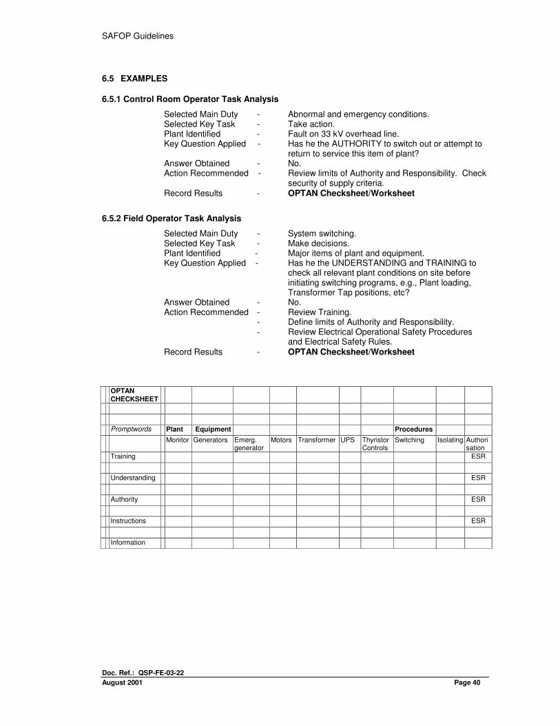
6.5.1 Control Room Operator Task Analysis
Selected Main Duty - Abnormal and emergency conditions. Selected Key Task - Take action. Plant Identified - Fault on 33 kV overhead line. Key Question Applied - Has he the AUTHORITY to switch out or attempt to
return to service this item of plant? Answer Obtained - No. Action Recommended - Review limits of Authority and Responsibility. Check
security of supply criteria. Record Results - OPTAN Checksheet/Worksheet
6.5.2 Field Operator Task Analysis
Selected Main Duty - System switching. Selected Key Task - Make decisions. Plant Identified - Major items of plant and equipment. Key Question Applied - Has he the UNDERSTANDING and TRAINING to
check all relevant plant conditions on site before initiating switching programs, e.g., Plant loading, Transformer Tap positions, etc?
Answer Obtained - No. Action Recommended - Review Training.
- Define limits of Authority and Responsibility. - Review Electrical Operational Safety Procedures
and Electrical Safety Rules. Record Results - OPTAN Checksheet/Worksheet
OPTAN
CHECKSHEET
Promptwords Plant Equipment Procedures
Monitor Generators Emerg. generator
Motors Transformer UPS Thyristor Controls
Switching Isolating Authorisation
Training ESR
Understanding ESR
Authority ESR
Instructions ESR
Information
SAFOP Guidelines
Doc. Ref.: QSP-FE-03-22
August 2001 Page 41
Figure 6-1 - OPTAN STUDY SEQUENCE
START
2. SELECT MAIN DUTY
3. SELECT KEY TASK
5. APPLY KEY QUESTION
6. OBTAIN ANSWERYES/NO/IT DEPENDS
9. REPEAT STEPS 5 TO 8 FOR ALLKEY QUESTIONS
7. RECOMMEND ACTIONS
8. RECORD
10. REPEAT STEPS 4 TO 9 FORALL ITEMS/ PLANT/ EQUIPMENT/
PROCEDURES
11. REPEAT STEPS 3 TO 10 FORALL KEY TASKS
12. REPEAT STEPS 2 TO 11 FORALL MAIN DUTIES
FINISH
4. IDENTY PLANT / EQUIPMENTPROCEDURES
1. SELECT OPERATOR
CONTROL ROOM/ FIELD
SAFOP Guidelines
Doc. Ref.: QSP-FE-03-22
August 2001 Page 42
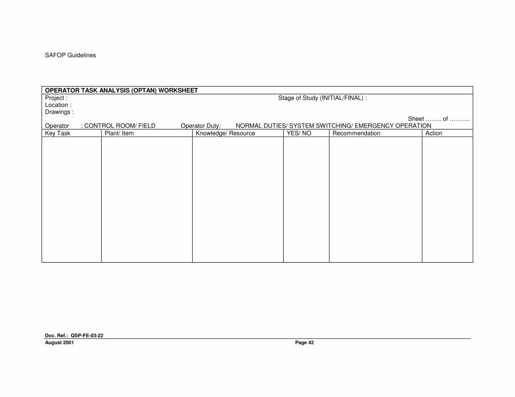
OPERATOR TASK ANALYSIS (OPTAN) WORKSHEET
Project : Stage of Study (INITIAL/FINAL) : Location : Drawings :
Sheet …….. of ………. Operator : CONTROL ROOM/ FIELD Operator Duty: NORMAL DUTIES/ SYSTEM SWITCHING/ EMERGENCY OPERATION
Key Task Plant/ Item Knowledge/ Resource YES/ NO Recommendation Action

SAFOP Guidelines
Doc. Ref.: QSP-FE-03-22
August 2001 Page 44
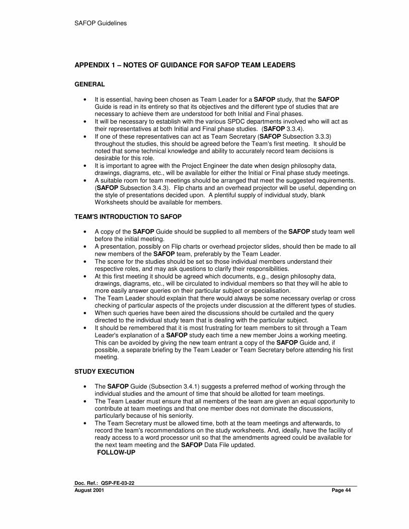
APPENDIX 1 – NOTES OF GUIDANCE FOR SAFOP TEAM LEADERS
GENERAL
• It is essential, having been chosen as Team Leader for a SAFOP study, that the SAFOP Guide is read in its entirety so that its objectives and the different type of studies that are necessary to achieve them are understood for both Initial and Final phases.
• It will be necessary to establish with the various SPDC departments involved who will act as their representatives at both Initial and Final phase studies. (SAFOP 3.3.4).
• If one of these representatives can act as Team Secretary (SAFOP Subsection 3.3.3) throughout the studies, this should be agreed before the Team's first meeting. It should be noted that some technical knowledge and ability to accurately record team decisions is desirable for this role.
• It is important to agree with the Project Engineer the date when design philosophy data, drawings, diagrams, etc., will be available for either the Initial or Final phase study meetings.
• A suitable room for team meetings should be arranged that meet the suggested requirements. (SAFOP Subsection 3.4.3). Flip charts and an overhead projector will be useful, depending on the style of presentations decided upon. A plentiful supply of individual study, blank Worksheets should be available for members.
TEAM'S INTRODUCTION TO SAFOP
• A copy of the SAFOP Guide should be supplied to all members of the SAFOP study team well before the initial meeting.
• A presentation, possibly on Flip charts or overhead projector slides, should then be made to all new members of the SAFOP team, preferably by the Team Leader.
• The scene for the studies should be set so those individual members understand their respective roles, and may ask questions to clarify their responsibilities.
• At this first meeting it should be agreed which documents, e.g., design philosophy data, drawings, diagrams, etc., will be circulated to individual members so that they will he able to more easily answer queries on their particular subject or specialisation.
• The Team Leader should explain that there would always be some necessary overlap or cross checking of particular aspects of the projects under discussion at the different types of studies.
• When such queries have been aired the discussions should be curtailed and the query directed to the individual study team that is dealing with the particular subject.
• It should be remembered that it is most frustrating for team members to sit through a Team Leader's explanation of a SAFOP study each time a new member Joins a working meeting. This can be avoided by giving the new team entrant a copy of the SAFOP Guide and, if possible, a separate briefing by the Team Leader or Team Secretary before attending his first meeting.
STUDY EXECUTION
• The SAFOP Guide (Subsection 3.4.1) suggests a preferred method of working through the individual studies and the amount of time that should be allotted for team meetings.
• The Team Leader must ensure that all members of the team are given an equal opportunity to contribute at team meetings and that one member does not dominate the discussions, particularly because of his seniority.
• The Team Secretary must be allowed time, both at the team meetings and afterwards, to record the team's recommendations on the study worksheets. And, ideally, have the facility of ready access to a word processor unit so that the amendments agreed could be available for the next team meeting and the SAFOP Data File updated.
FOLLOW-UP

SAFOP GUIDELINES
Doc. Ref.: QSP-FE-03-22
August 2001 Page 45
• The Team Leader should identify at team meeting which member or department is required to take action on a particular issue, and should ensure that he is given the authority to expect a satisfactory answer at subsequent meetings.
• Finally, the Team Leader should be satisfied that after both Initial and Final phase studies are complete that the Team Secretary has produced a comprehensive SAFOP Data File which can have an agreed circulation and, if necessary attached action list.
SAFOP Guidelines
Doc. Ref.: QSP-FE-03-22
August 2001 Page 46
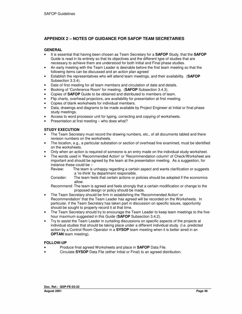
APPENDIX 2 – NOTES OF GUIDANCE FOR SAFOP TEAM SECRETARIES
GENERAL
• It is essential that having been chosen as Team Secretary for a SAFOP Study, that the SAFOP Guide is read in its entirety so that its objectives and the different type of studies that are necessary to achieve them are understood for both Initial and Final phase studies.
• An early meeting with the Team Leader is desirable before the first team meeting so that the following items can be discussed and an action plan agreed
• Establish the representatives who will attend team meetings, and their availability. (SAFOP Subsection 3.3.4).
• Date of first meeting for all team members and circulation of date and details.
• Booking of 'Conference Room' for meeting. (SAFOP Subsection 3.4.3).
• Copies of SAFOP Guide to be obtained and distributed to members of team.
• Flip charts, overhead projectors, are availability for presentation at first meeting.
• Copies of blank worksheets for individual members.
• Data, drawings and diagrams to be made available by Project Engineer at Initial or final phase study meetings.
• Access to word processor unit for typing, correcting and copying of worksheets.
• Presentation at first meeting – who does what? STUDY EXECUTION
• The Team Secretary must record the drawing numbers, etc., of all documents tabled and there revision numbers on the worksheets.
• The location, e.g., a particular substation or section of overhead line examined, must be identified on the worksheets.
• Only when an action is required of someone is an entry made on the individual study worksheet.
• The words used in 'Recommended Action' or ’Recommendation column' of Check/Worksheet are important and should be agreed by the team at the presentation meeting. As a suggestion, for instance these could be :- Review: The team is unhappy regarding a certain aspect and wants clarification or suggests
a 're-think' by department responsible. Consider: The team feels that certain actions or policies should be adopted if the economics
allow. Recommend: The team is agreed and feels strongly that a certain modification or change to the
proposed design or policy should be made.
• The Team Secretary should be firm in establishing the 'Recommended Action' or Recommendation' that the Team Leader has agreed will be recorded on the Worksheets. In particular, if the Team Secretary has taken part in discussion on specific issues, opportunity should be sought to properly record it at that time.
• The Team Secretary should try to encourage the Team Leader to keep team meetings to the five-hour maximum suggested in this Guide (SAFOP Subsection 3.4.2).
• Try to assist the Team Leader in curtailing discussions on specific aspects of the projects at individual studies that should be taking place under a different individual study. (I.e. predicted action by a Control Room Operator in a SYSOP team meeting when it is better aired in an OPTAN team meeting).
FOLLOW-UP
• Produce final agreed Worksheets and place in SAFOP Data File.
• Circulate SYSOP Data File (either Initial or Final) to an agreed distribution.
SAFOP GUIDELINES
Doc. Ref.: QSP-FE-03-22
August 2001 Page 47
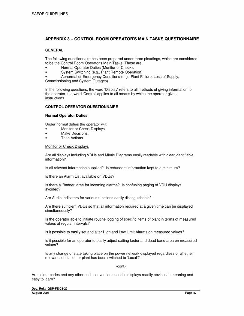
APPENDIX 3 – CONTROL ROOM OPERATOR'S MAIN TASKS QUESTIONNAIRE
GENERAL The following questionnaire has been prepared under three pleadings, which are considered to be the Control Room Operator's Main Tasks. These are:
• Normal Operator Duties (Monitor or Check).
• System Switching (e.g., Plant Remote Operation).
• Abnormal or Emergency Conditions (e.g., Plant Failure, Loss of Supply, Commissioning and System Outages). In the following questions, the word 'Display' refers to all methods of giving information to the operator, the word 'Control' applies to all means by which the operator gives instructions. CONTROL OPERATOR QUESTIONNAIRE Normal Operator Duties Under normal duties the operator will:
• Monitor or Check Displays.
• Make Decisions.
• Take Actions. Monitor or Check Displays Are all displays including VDUs and Mimic Diagrams easily readable with clear identifiable information? Is all relevant information supplied? Is redundant information kept to a minimum? Is there an Alarm List available on VDUs? Is there a 'Banner' area for incoming alarms? Is confusing paging of VDU displays avoided? Are Audio Indicators for various functions easily distinguishable? Are there sufficient VDUs so that all information required at a given time can be displayed simultaneously? Is the operator able to initiate routine logging of specific items of plant in terms of measured values at regular intervals? Is it possible to easily set and alter High and Low Limit Alarms on measured values? Is it possible for an operator to easily adjust setting factor and dead band area on measured values? Is any change of state taking place on the power network displayed regardless of whether relevant substation or plant has been switched to ‘Local’?
-cont.-
Are colour codes and any other such conventions used in displays readily obvious in meaning and easy to learn?
SAFOP Guidelines
Doc. Ref.: QSP-FE-03-22
August 2001 Page 48
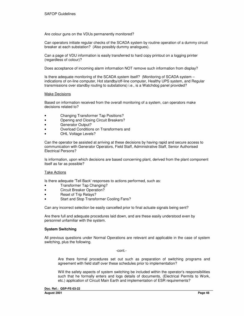
Are colour guns on the VDUs permanently monitored? Can operators initiate regular checks of the SCADA system by routine operation of a dummy circuit breaker at each substation? (Also possibly dummy analogues). Can a page of VDU information is easily transferred to hard copy printout on a logging printer (regardless of colour)? Does acceptance of incoming alarm information NOT remove such information from display? Is there adequate monitoring of the SCADA system itself? (Monitoring of SCADA system – indications of on-line computer, Hot standby/off-line computer, Healthy UPS system, and Regular transmissions over standby routing to substations) i.e., is a Watchdog panel provided? Make Decisions Based on information received from the overall monitoring of a system, can operators make decisions related to?
• Changing Transformer Tap Positions?
• Opening and Closing Circuit Breakers?
• Generator Output?
• Overload Conditions on Transformers and
• OHL Voltage Levels? Can the operator be assisted at arriving at these decisions by having rapid and secure access to communication with Generator Operators, Field Staff, Administrative Staff, Senior Authorised Electrical Persons? Is information, upon which decisions are based concerning plant, derived from the plant component itself as far as possible? Take Actions Is there adequate 'Tell Back' responses to actions performed, such as:
• Transformer Tap Changing?
• Circuit Breaker Operation?
• Reset of Trip Relays?
• Start and Stop Transformer Cooling Fans? Can any incorrect selection be easily cancelled prior to final actuate signals being sent? Are there full and adequate procedures laid down, and are these easily understood even by personnel unfamiliar with the system. System Switching All previous questions under Normal Operations are relevant and applicable in the case of system switching, plus the following.
-cont.-
Are there formal procedures set out such as preparation of switching programs and agreement with field staff over these schedules prior to implementation? Will the safety aspects of system switching be included within the operator's responsibilities such that he formally enters and logs details of documents, (Electrical Permits to Work, etc.) application of Circuit Main Earth and implementation of ESR requirements?
SAFOP GUIDELINES
Doc. Ref.: QSP-FE-03-22
August 2001 Page 49
Abnormal or Emergency Conditions All items discussed under Normal Operation and System Switching are relevant and applicable in the case of Abnormal or Emergency Conditions plus the following: Is full cognisance taken of the need to ensure stress is avoided with the presentation of major emergency alarms (for instance, subdued chimes rather than strident bells are favoured as audio indicators)? Are certain Alarms assigned priorities over others? Is Acceptance of incoming alarms achieved easily, say with a single dedicated key action? Is minimal information put into the banner area and full description given in the alarm list AND on the substation display? Does the operator have precise instructions as to his actions on receipt of foreseeable emergency situations arising? Is there adequate emergency lighting available to ensure an operator can still perform his duties at times of loss of main lighting? Is the time-tagging aspect, particularly on logging printers, sufficiently discriminatory to provide adequate facilities for post fault analysis of power system failures? Can emergency procedures be implemented whether or not an operator knows what is wrong, i.e., can they be 'symptom' based rather 'than event based? Can commissioning of plant on to the SCADA System, both as part of this project and in the future, be carried out effectively to plant simulators, and such commissioning not disrupt the power equipment in any way?
SAFOP Guidelines
Doc. Ref.: QSP-FE-03-22
August 2001 Page 50
APPENDIX 4 – FIELD OPERATOR'S MAIN TASKS QUESTIONNAIRE
GENERAL A Field Operator's tasks can be considered under three main headings. These are: Normal Operator Duties : Inspecting substation plant and overhead lines. System Switching : Operating Plant on site. Abnormal or Emergency : Commissioning and Maintaining Plant, Post Fault Reporting and Investigations.
To determine if plant can be easily inspected and operated, and supporting documentation is adequate, a list of questions is detailed below. FIELD OPERATOR QUESTIONNAIRE Normal Operator Duties Under normal operator duties he will:
• Perform inspection of substations and overhead lines.
• Report Main Plant or Auxiliaries requiring attention.
• Take immediate action on potentially serious plant conditions. Has the operator performing inspection been made familiar with the plant when it was installed? Has the operator been given a checklist on specific items to be inspected? Has the operator been given instructions on what fault or defect to report immediately? Has the operator been instructed not to leave the ground in substation compounds containing exposed high voltage conductors? Has the operator been instructed not to pursue investigations into 'noises' from ’live gear' without first reporting to the Control Person and agreeing a prudent form of action? Is the operator familiar with the relevant details of the type of construction of the overhead line being inspected? Does the operator have knowledge of interlocks on operating devices of various plants? Does the operator know the significance of local and remote alarms or indications that may occur when he is operating? Does the operator know the significance of transformer tap positions, tap change control modes and circuit loading prior to initiating switching programs? Abnormal or Emergency Conditions Under these headings the operator may be commissioning plant and auxiliaries or dealing with post-fault investigations.
-cont.-
Is the substation to be commissioned and then taken under the scope of the ESR?
SAFOP GUIDELINES
Doc. Ref.: QSP-FE-03-22
August 2001 Page 51
Will the substation be subject to the ESR when the last connection is to be made to conductors that can be made alive from the system? Will a Senior Authorised Electrical Person (SAEP) become involved in the protection and voltage pressure testing before the substation is connected to the system? Will SPDC provide technical staff to monitor turnkey contractors' staff when substation is partially commissioned? Has the operator the training and understanding to identify abnormal plant conditions and emergency situations, e.g.:
• A tap changer stuck between taps?
• A circuit breaker locked out?
• Relay flag operations?
• Low battery volts?
• Low oil levels?
• Buchholz gas alarms, etc.?
Has the operator been told not to climb any structure without safety documentation? Has the operator training, understanding and instructions to carry out minor tasks on plant, and equipment, e.g.:
• Reset relay flags and indicators?
• Test cooling fans?
• Reset maximum reading instruments?
• Change silica gel breathers? Have the operator instructions to inspect and check:
• Portable earths?
• Posts, chains, ropes, etc. (temporary barriers in compounds)? Is the operator aware that when performing battery inspections, smoking and the presence of naked flames are prohibited in battery rooms or in the vicinity of battery installations? System Switching (Operating Plant) When performing switching operations, has the operator been made familiar and received training on:
• Operation of 132 kV Disconnector?
• Operation of 132 kV Earth Switches?
• Operation of 132 kV Circuit Breakers (Local)?
• Operation of 33 kV Circuit Breakers (Local) including isolating, locking-off and earthing both circuit and busbars?
• Operation and control of transformer tap changers?
• Application of Circuit Main Earths to 132 kV and 33 kV coppers?
• Operation of Tap Change Controls?
• Operation of Low Voltage Switchboards? Has the operator been trained in the use of correct voltage detectors before applying CME’s to?
• Exposed coppers?
• Switchgear spouts?
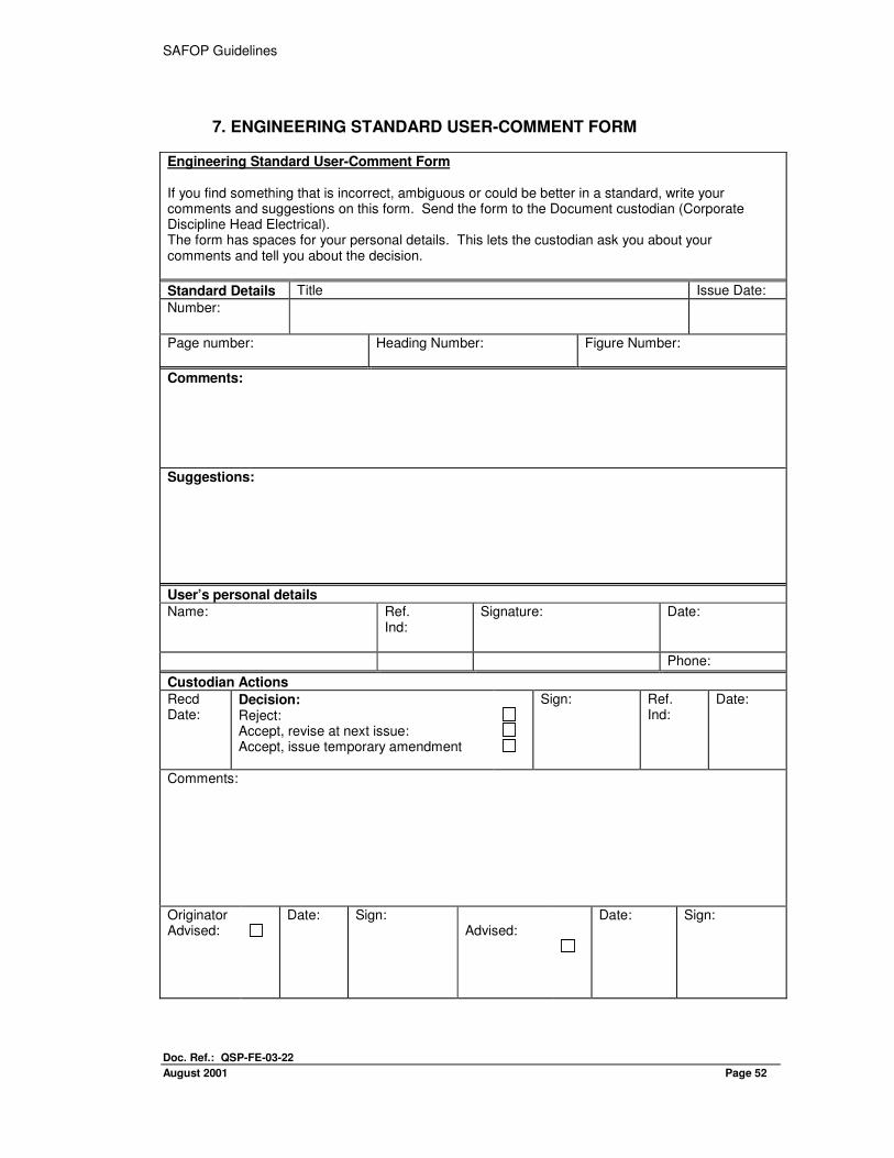
SAFOP Guidelines
Doc. Ref.: QSP-FE-03-22
August 2001 Page 52
7. ENGINEERING STANDARD USER-COMMENT FORM
Engineering Standard User-Comment Form If you find something that is incorrect, ambiguous or could be better in a standard, write your comments and suggestions on this form. Send the form to the Document custodian (Corporate Discipline Head Electrical). The form has spaces for your personal details. This lets the custodian ask you about your comments and tell you about the decision.
Standard Details Title Issue Date:
Number:
Page number:
Heading Number: Figure Number:
Comments:
Suggestions:
User’s personal details
Name:
Ref. Ind:
Signature: Date:
Phone:
Custodian Actions
Recd Date:
Decision: Reject: Accept, revise at next issue: Accept, issue temporary amendment
Sign: Ref. Ind:
Date:
Comments:
Originator Advised:
Date: Sign: Advised:
Date: Sign: