Embed Size (px)
DESCRIPTION
The report gives the clear docs of building a electric race kart
Citation preview
Visvesvaraya Technological University Belgaum
Minor Project Report
SAE Eco kart Submitted in partial fulfilment of the requirements of the Bachelor Degree of
Bachelor of Engineering In
Automobile Engineering Submitted By
Aditya Jha 2BV12AU001
Durbar Ghosh 2BV12AU014
Kunal Habib 2BV12AU021 Sindhoor Hegde 2BV12AU048
Under the Guidance
of Dr. Siddhalingeshwar I.G.
Department of Automobile Engineering
B. V. Bhoomaraddi College of Engineering & Technology, Hubli-580031
(An Autonomous Institution affiliated to VTU, Belgaum)
2014-2015
DEPT. OF AUTOMOBILE ENGINEERING, BVBCET Page 2
K.L.E SOCIETY’S
B.V.BHOOMRADDI COLLEGE OF ENGINEERING & TECHNOLOGY,
HUBLI-580031
(An Autonomous Institution Affiliated to VTU, Belgaum)
2014 - 2015
DEPARTMENT OF AUTOMOBILE ENGINEERING
CERTIFICATE
This is to certify that the report titled “SAE ECO-KART” is a bonafide record of
the Minor Project carried successfully by the students:
Aditya Jha (2BV12AU001)
Durbar Ghosh (2BV12AU014)
Kunal Habib (2BV12AU021)
Sindhoor Hegde (2BV12AU048)
As a part of Minor Project(AUP301) of Sixth Semester Automobile
Engineering syllabus, for the year 2014-2015.
Guide H.O.D Principal
Dr. Siddhalingeshwar I.G. Dr. Anil Badiger Dr. Ashok S. Shettar
Name of the Examiners Signature with date
1.
2

DEPT. OF AUTOMOBILE ENGINEERING, BVBCET Page 3
SAE ECO KART

DEPT. OF AUTOMOBILE ENGINEERING, BVBCET Page 4
ACKNOWLEDGEMENTS
Firstly we would like to thank AUTOMOBILE Engineering Department,
B.V.B.C.E.T for giving us this great opportunity to carry out this Minor Project.
We are very grateful to the Review Committee, Mr. Aditya M. Deshpande, Dr.
Siddhalingeshwar I.G. and Nagaraj Ekabote, our project would never be a success
if they had not supported us. We like to express our sincere regards to our project
guide Dr. Siddhalingeshwar I.G. who has guided and helped us in every possible
manner throughout the journey. We are very thankful to our Prof. Nagaraj
Ekabote who taught us and helped us for learning the software and tools for
successfully performing analysis for our project, and Prof. Balachandra Halemani
who helped us in learning tools for designing. Also we would like to thank Mr.
Ravikiran Murthy and his team for helping us out in the technical issues. We
express our gratitude to all other teaching faculty of Automobile Department for
their kind support. Lastly we would like thank all the persons directly or indirectly
involved in success of our project.

DEPT. OF AUTOMOBILE ENGINEERING, BVBCET Page 5
CONTENTS PAGES
1. Introduction to ECO-KART 9
1.1. Objectives for the design 10
1.2. Major Components of Eco Kart: 10
2. Electrical System 11
2.1. Battery 11
2.2. Controller 14
2.3. Pulse-Width Modulator 15
2.4. Throttle or Speed Control 16
2.5. Forward & Reverse 17
3. POWER TRAIN 18
3.1. Motor 18
3.2. Calculations for Battery discharge. 18
3.3. Drive Train 19
3.4. Calculations of speed of the vehicle. 20
3.5. Calculation for size of Power shaft 22
3.6. Gradability 23
4. Steering:
4.1. Introduction 24
4.2. Ackermann steering geometry 24
4.2.1. Advantages of Ackermann steering 25
4.2.2. Design & choice of geometry 25
4.3. 27
4.3.1. Toe in/out setting 27
4.3.2. Ackerman 27
4.3.3. Caster 27
4.3.4. Camber 27
4.3.5. Front width 27
4.4. Steering parts Creo-parametric 2.0 model 28
5. Tyres: 34
5.1. Available tyres 34
5.2. General setup condition for Eco-kart 35
6. Braking System: 36
6.1. Abstract ` 36
6.2. Objectives 36
6.3. 36
6.3.1. Requirements 36
6.3.2. Different Conditions 36
6.4. Brake Subsystems 37

DEPT. OF AUTOMOBILE ENGINEERING, BVBCET Page 6
6.4.1. Braking Components & Configurations 37
6.5. Braking System Design 38
6.5.1. Master cylinder 38
6.5.2. Brake rotors 39
6.5.3. Brake pedal 39
6.5.4. Brake fluid 41
6.6. Kinematics of braking 43
6.6.1. Assumptions 43
6.6.2. Typical Measured Deceleration time-history 43
6.6.3. Retardation Force 43
6.6.4. Load Transfer 44
6.7. Brake calculations 45
6.7.1. Brake pedal 45
6.8. Vehicle Dynamics 45
6.8.1. Static axle load distribution 45
6.8.2. Relative centre of gravity height 45
6.8.3. Dynamic axle loads 46
6.8.4. Wheel lock 47
6.8.5. Brake torque 47
6.8.6. Foundation brake 47
6.8.7. Clamp Load 48
7. Frame 52
7.1. Introduction 52
7.2. Objectives 52
7.3. Design of frame 52
7.3.1. Safety 52
7.3.2. Ergonomics and comfort 52
7.3.3. Dimensions 53
7.3.4. Material selection 54
7.3.5. Structural considerations 57
7.3.6. Accessibility 58
7.3.7. Manufacturability 58
7.3.8. Body & floor pan 58
7.4. Model & Analysis 59
7.4.1. Design alternatives 59
7.4.2. Static Load 60
7.4.3. Frontal Impact 62
8. Assembly & Mountings 64
8.1. Rods & Fasteners 64
8.2. Mounts 64
8.3. Innovation in bumper design 68
8.4. Weight Distribution 69
9. References 70

DEPT. OF AUTOMOBILE ENGINEERING, BVBCET Page 7
LIST OF FIGURES/TABLES/GRAPHS PAGES
1. Fig 1: World record Fastest Acceleration 9
2. Fig 2.1: battery 12
3. Fig 2.2: Schematic of controller 14
4. Fig 2.3: Controller 14
5. Fig 2.4: Schematic of PWM 15
6. Fig 2.5: Layout of Motor controller 17
7. Fig 3.1: Motor 18
8. Table 3.1: CVT vs Chain sprocket transmission 19
9. Fig 4.1. Ackerman steering 24
10. Fig 4.2. Ackerman steering Geometry 26
11. Fig 4.3. Steering assembly 28
12. Fig 4.4 Tie rod parts 28
13. Fig 4.5 Tie rod and Ackerman arm joint 29
14. Fig 4.6. Steering column with Drop arm 29
15. Fig 4.7 Steering Wheel 29
16. Fig 4.8. Left stub axle dimensions 30
17. Fig 4.9. ISO-7379 Bolt & Nut 30
18. Fig 4.10. Inner wheel angle 31
19. Fig 4.11. Inner wheel turning radius 31
20. Fig 4.12. Outer wheel angle 32
21. Fig. 4.13 Outer wheel turning radius 32
22. Table. 5.1. Available tyres 34
23. Table. 5.2. Dimensions of available tyres 34
24. Fig. 6.1. Brake system layout 38
25. Fig. 6.2. Brake master cylinder 38
26. Fig. 6.3. Rotor 39
27. Fig. 6.4. Brake pedal 40
28. Table. 6.1. List of popular mass produced brake master cylinder along with diameter and their areas. 41 29. Table 6.2. Brake system assembly parts 42
30. Graph 6.1. Deceleration vs Time 43
31. Graph 6.2. Velocity vs Time 43
32. Graph 6.3. Displacement vs time 43
33. Fig. 6.5: Thermal 50
34. Fig. 6.6: Stress 51
DEPT. OF AUTOMOBILE ENGINEERING, BVBCET Page 8
35. Fig. 6.7: Strain 51
36. Fig. 6.8: Total Deformation 51
37. Fig. 7.1. Seeting position & dimension measurement 53
38. Fig. 7.2. Dimensions of frame ( top view ) 53
39. Fig. 7.3. Dimensions of frame (side view ) 54
40. Table 7.1. Properties of materials 55
41. Table. 7.2. Tubes of available size 56
42. Fig. 7.4. Iteration 1 59
43. Fig. 7.5. Iteration 2 59
44. Fig. 7.6. Iteration 3 59
45. Fig. 7.7. Stress 60
46. Fig. 7.8. Maximum Deformation 60
47. Fig. 7.9. Factor of Safety 61
48. Fig. 7.10. Forces acting while impact 61
49. Fig. 7.11. Stress 62
50. Fig. 7.12. Maximum Deformation 62
51. Fig. 7.13. Factor of Safety 63
52. Fig. 8.1. Front Bumper 68
53. Fig. 8.2. Distances of Weights from front axle 69

DEPT. OF AUTOMOBILE ENGINEERING, BVBCET Page 9
1. Introduction to ECO-KART:
An SAE Eco Kart vehicle is a single-seat, motor driven go kart building
competition. Undergraduate students from multiple academic fields
collaborated to design and manufacture a safe, high-performance, cost-efficient
Baja vehicle to serve as a prototype for mass production. The students utilized
and refined both financial procedures and engineering analyses to complete this
objective while Strictly following the prescribed SAE rules.
The main intention behind that is to allow students to apply theory learnt class
to a practical situation. Provide students a favour of working in a simulated
industry environment. Students get an opportunity to apply theory learned in
classes to a practical engineering project. Students the knowledge and
experience in working in a simulated industry environment. Students are
challenged to provide an innovative design that meets the criteria of the design
competition.
Fig 1: World record Fastest Acceleration [0-60mph in 3.4 sec]

DEPT. OF AUTOMOBILE ENGINEERING, BVBCET Page 10
1.1. Objectives for the design
1. 100% pollution free operation,
2. Avoiding uses of conventional fossil fuel,
3. Safety and ergonomic consideration,
4. Maneuverability,
5. Energy efficient[light weight, aero dynamics],
6. Range of operation,
7. Aesthetics,
8. Easily accessible and repairable
9. Team identity and design novelty [Style, name, logo]
1.2. Major Components of Eco Kart:
1. Power Unit Motor
Motor controller
Battery
Battery Management System
Transmission
2. Wheels & Tires
3. Steering System
4. Braking System
5. Frame
6. Body design
7. Safety Equipments
DEPT. OF AUTOMOBILE ENGINEERING, BVBCET Page 11
2. Electrical system
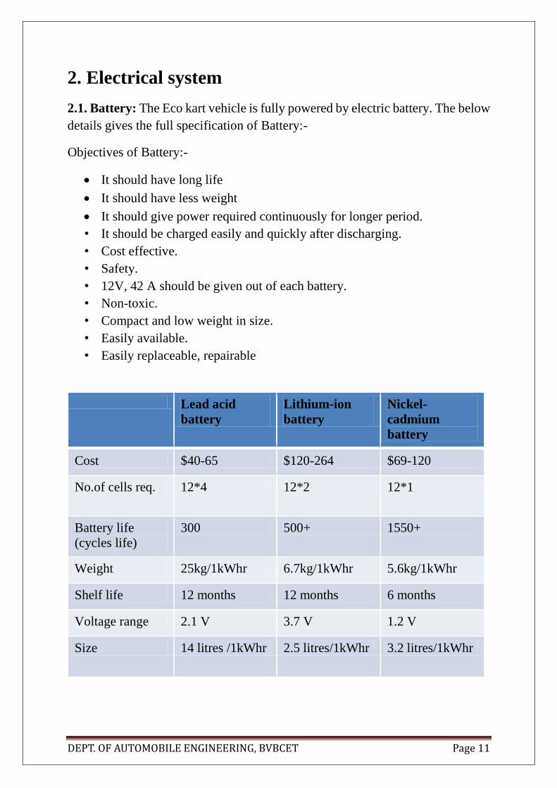
2.1. Battery: The Eco kart vehicle is fully powered by electric battery. The below
details gives the full specification of Battery:-
Objectives of Battery:-
It should have long life
It should have less weight
It should give power required continuously for longer period.
• It should be charged easily and quickly after discharging.
• Cost effective.
• Safety.
• 12V, 42 A should be given out of each battery.
• Non-toxic.
• Compact and low weight in size.
• Easily available.
• Easily replaceable, repairable
Lead acid
battery
Lithium-ion
battery
Nickel-
cadmium
battery
Cost $40-65 $120-264 $69-120
No.of cells req. 12*4 12*2 12*1
Battery life
(cycles life)
300 500+ 1550+
Weight 25kg/1kWhr 6.7kg/1kWhr 5.6kg/1kWhr
Shelf life 12 months 12 months 6 months
Voltage range 2.1 V 3.7 V 1.2 V
Size 14 litres /1kWhr 2.5 litres/1kWhr 3.2 litres/1kWhr

DEPT. OF AUTOMOBILE ENGINEERING, BVBCET Page 12
Availability Easily avail Delivery at 2-3
days from
ordering
Difficult to gain
has much
powerful
Overcharging
tolerance
moderate high Very low
Table 2.1. Specifications of batteries
We have chosen battery from specification metrics table due to its efficiency of
quick charging and efficiency to discharge more power for longer time.
Chemical equation:
C + LiCoO2 LiC6 + Li0.5CoO2
Fig 2.1: battery
Battery type- Lithium-ion
Battery Voltage=12 V
No. of batteries required at one
time=4
Nominal voltage: 12.8V
Typical capacity: 20Ah
Max continuous discharge current
20A
Max pulse discharge current : 60A
Work voltage range: 9.2V~14.6V
Size: 180*75*165mm
Weight: 2.4kg each
The Batteries are connected in series so that all the 4 battery equals one
battery of 48V of 80Ah of current.

DEPT. OF AUTOMOBILE ENGINEERING, BVBCET Page 13
The Battery is connected to Battery safety system. It is installed so as to
protect the electrical systems and equipments from fluctuating voltages released
from the battery.
The Battery safety system consists of:-
1. Main switch.
2. Ignition switch.
3. Fuse.
4. Miniature circuit board.
5. Regulator of nominal voltage.
6. Contactor
Along with these, the system consists of KILL SWITCHES which is
connected before main switch near the driver as emergency to stop the flow of
current to electrical equipments.
The layout of Battery management system is given below:-
Battery
MAIN SWITCH
MINIATURE CIRCUIT BOARD
CONTACTOR
FUSE
REGULATOR
CONTROLLER
BRAKE LIGHT
POTENTIOMETER
BR
AK
E
PED
AL&
HA
ND
BR
AK
E
Ignition Switch

DEPT. OF AUTOMOBILE ENGINEERING, BVBCET Page 14
2.2. CONTROLLER
Objectives of motor control • Sustain fluctuating current and voltages of battery input and give a constant desired
output current.
• Throttle controlling
• Should be able to safeguard the motor by unnatural currents
• Cost effective
• Highly efficient
• Easily and cheaply available
• Should be used for multi purpose.
The controller is system which controls the speed and direction of rotation
of the Motor. It has a circuit board where a number of nominal capacity
capacitors, circuit links, modules etc., this controller connects the Motor in order
to operate it at required speed using the potentiometer signal according to given
Throttle.
The schematic circuit of Controller. The controller unit figure is shown below:-
Fig 2.2: Schematic of controller Fig 2.3: Controller

DEPT. OF AUTOMOBILE ENGINEERING, BVBCET Page 15
The specification of the controller is given below:-
Voltage - 48V
Current-35-42amp
Standby Battery Current: < 0.5mA.
5V Sensor Supply Current: 40mA.
Size: 122x87x32mm
Power requirement:10-50VDC
Rated current: 60A(Maximum
output current)
Frequency:15000HZ
Control Motor Power : 0.01-3000W,
Analogue Brake and Throttle Input:
05 Volts.
Motor Current Limit, 1 minute: 100A.
Motor Current Limit,continuous: 60A
.
2.3. Pulse-Width Modulator
The Controller contains a Pulse-width modulator circuit which controls the
fluctuating input voltages into mean output voltages.
Pulse Width Modulation circuit that is used to control the speed of the
motor by means of varying voltage supply to it. The Pulse Width Modulation is
connected to the
motor’s positive terminal and the negative is grounded.
The fig of Circuit (a) is shown below:-
Fig 2.4: Schematic of pulse width modulator
a
DEPT. OF AUTOMOBILE ENGINEERING, BVBCET Page 16
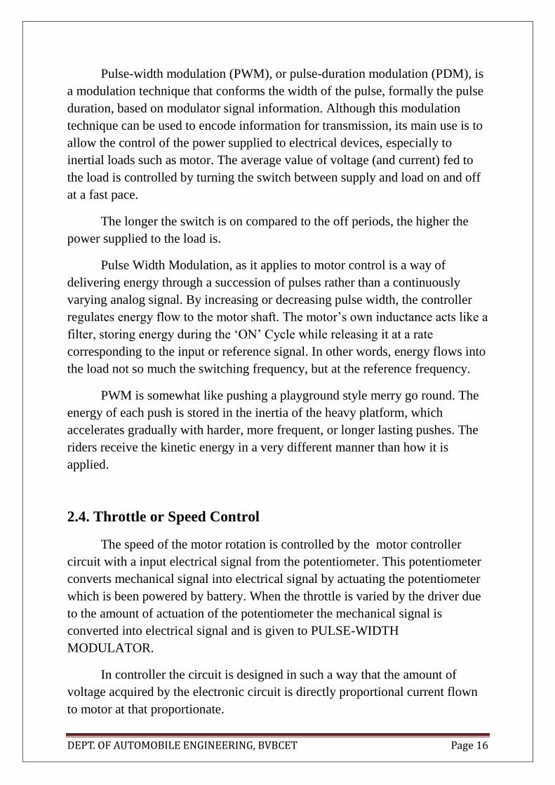
Pulse-width modulation (PWM), or pulse-duration modulation (PDM), is
a modulation technique that conforms the width of the pulse, formally the pulse
duration, based on modulator signal information. Although this modulation
technique can be used to encode information for transmission, its main use is to
allow the control of the power supplied to electrical devices, especially to
inertial loads such as motor. The average value of voltage (and current) fed to
the load is controlled by turning the switch between supply and load on and off
at a fast pace.
The longer the switch is on compared to the off periods, the higher the
power supplied to the load is.
Pulse Width Modulation, as it applies to motor control is a way of
delivering energy through a succession of pulses rather than a continuously
varying analog signal. By increasing or decreasing pulse width, the controller
regulates energy flow to the motor shaft. The motor’s own inductance acts like a
filter, storing energy during the ‘ON’ Cycle while releasing it at a rate
corresponding to the input or reference signal. In other words, energy flows into
the load not so much the switching frequency, but at the reference frequency.
PWM is somewhat like pushing a playground style merry go round. The
energy of each push is stored in the inertia of the heavy platform, which
accelerates gradually with harder, more frequent, or longer lasting pushes. The
riders receive the kinetic energy in a very different manner than how it is
applied.
2.4. Throttle or Speed Control
The speed of the motor rotation is controlled by the motor controller
circuit with a input electrical signal from the potentiometer. This potentiometer
converts mechanical signal into electrical signal by actuating the potentiometer
which is been powered by battery. When the throttle is varied by the driver due
to the amount of actuation of the potentiometer the mechanical signal is
converted into electrical signal and is given to PULSE-WIDTH
MODULATOR.
In controller the circuit is designed in such a way that the amount of
voltage acquired by the electronic circuit is directly proportional current flown
to motor at that proportionate.

DEPT. OF AUTOMOBILE ENGINEERING, BVBCET Page 17
2.5. Forward & Reverse
The controller has the function of converting the polarities of the current
so as to change the direction of rotation of the motor. A switch to change the
polarity is been given on the Controller circuit itself.
Fig 2.5: The layout of Motor Controller

DEPT. OF AUTOMOBILE ENGINEERING, BVBCET Page 18
3. POWER TRAIN
In Eco-kart the power train includes the Motor and there-after it connects to
Transmission system.
3.1. MOTOR
The important component of the eco-kart and also the powertrain system
which is used for propelling of the vehicle. The motor specification is given
below:-
Rated Power (W) -- 3000
Rated Voltage (V) -- 48
Speed Range (rpm) -- 20003500
Efficiency (%) -- >80
Noise (dB) -- <65
Loading--110kg
Peak Torque--12.5Nm@2500rpm
Weight (kg) -- 5
Fig 3.1: Motor
3.2. Calculations for Battery discharge.
As all the electrical components of the vehicle is been listed the battery
discharge is to be determined respective of time
DEPT. OF AUTOMOBILE ENGINEERING, BVBCET Page 19
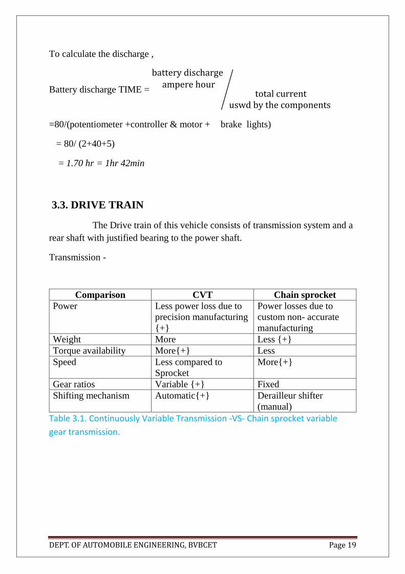
To calculate the discharge ,
Battery discharge TIME =
battery discharge ampere hour
total currentuswd by the components
⁄
=80/(potentiometer +controller & motor + brake lights)
= 80/ (2+40+5)
= 1.70 hr = 1hr 42min
3.3. DRIVE TRAIN
The Drive train of this vehicle consists of transmission system and a
rear shaft with justified bearing to the power shaft.
Transmission -
Comparison CVT Chain sprocket
Power Less power loss due to
precision manufacturing
{+}
Power losses due to
custom non- accurate
manufacturing
Weight More Less {+}
Torque availability More{+} Less
Speed Less compared to
Sprocket
More{+}
Gear ratios Variable {+} Fixed
Shifting mechanism Automatic{+} Derailleur shifter
(manual)
Table 3.1. Continuously Variable Transmission -VS- Chain sprocket variable
gear transmission.

DEPT. OF AUTOMOBILE ENGINEERING, BVBCET Page 20
Thus, from above chart it is decided that CVT to be used as the transmission
system.
CVT used - Belt type, Scooty pep.
CVT ratio @ different speeds
@1300 rpm = 22.11
@1700 rpm = 16.23
@2000 rpm = 8.997
@2500 rpm = 6.33
@3500 rpm = 4.884
The Motor shaft is directly connected to CVT Driver wheel so as to
reduce Primary reduction ratio to 1. Now the CVT through Belt drive runs the
Driven Wheel. The Driven has an advantage of connecting power shaft through
itself. This is an innovation of connecting Power shaft directly to the rotating
shaft by welding and other joining process without disturbing the variable
wheel of CVT and Clutch assembly.
The Power shaft is then connected to the Rear Wheels with support of
bearings of justified series no.
3.4. Calculations of speed of the vehicle.
1. Motor RPM : 1300 rpm
Wheel diameter : 11 inch (0.2794m)
Primary Reduction = 1
CVT input RPM= 1300 RPM
CVT Ratio at 1300 RPM is 22.11
Power shaft rpm = 1300/22.11
=58.79 RPM

DEPT. OF AUTOMOBILE ENGINEERING, BVBCET Page 21
Speed (Kmph) = Power shaft rpm * 𝜋* Wheel Diameter* 60/1000
=58.79 *3.14*0.2794*60*10-3
= 3.09 Kmph.
2. Motor RPM : 2500 rpm
Wheel diameter=0.2749
Primary reduction= 1
CVT input rpm = 2500 rpm
CVT ratio at 2500 rpm =6.33
Power shaft rpm = 2500/6.33
= 379.70 RPM
Speed (Kmph) = Power shaft rpm * 𝜋* Wheel Dia * 60/1000
=379.70*3.14*0.2794*60*10-3
=19.98 Kmph.
3. Motor RPM : 3500 rpm
Wheel diameter=0.2749
Primary reduction= 1
CVT input rpm = 3500 rpm
CVT ratio at 3500 rpm =4.884
Power shaft rpm = 3500/4.884
=716.625 RPM
Speed (Kmph) = Power shaft rpm * 𝜋* Wheel Dia * 60/1000
=716.625*3.14*0.2794*60*10-3
= 39.85Kmph.

DEPT. OF AUTOMOBILE ENGINEERING, BVBCET Page 22
Torque on the wheels
The maximum motor torque = 12.5Nm Transmission efficiency = 70% = 0.7
Drive torque (Nm) = Motor Torque * combined gear ratio * transmission
efficiency
Combined gear ratio = Primary reduction * CVT Ratio
1) @1300 rpm
Drive Torque = 12.0* 1 * 22.11 * 0.7 = 185.724 N-m
2) @ 2000 rpm
Drive Torque =12.0* 1 * 8.997*0.7 =75.574 N-m
3) @ 3500rpm
Drive Torque =12.0*1*4.884*0.7 = 41.02 N-m
3.5. Calculation for size of Power shaft
The power shaft size is available at standard size based upon its inner
thickness and outer diameter. The material is AISI/SAE-1080 stainless steel.
Thus formula to find Diameter of Power shaft is
𝜏
𝑟 =
𝑇
𝐽
𝜏= Shear Stress= 3.2MPa
T=Torque supplied = 185.724 N/mm
J= Polar moment of Inertia
r= radius of the shaft
3.2
𝑟 =
185.724
𝜋∗𝑟^4/32
r = 18 .10 mm Outer diameter = 36.20 mm
But, the nearest available safe size of the shaft is 38.10 mm having thickness of
6mm.

DEPT. OF AUTOMOBILE ENGINEERING, BVBCET Page 23
Vehicle Tractive Effort (or) Drive Torque
Drive Force = Drive torque / Wheel Radius
Calculation
1) 185.724/ 0.2794 = 664.72 N
2) 75.574 / 0.2794 = 270.48 N
3) 41.02 / 0.2794 = 146.81 N
3.6. Gradability
Drive force = mg sin Ɵz
m = 140 kg
g = 9.81 m/s-2
Ɵ = sin-1 ( Drive force / mg )
Calculation
Ɵ = sin-1( 664.72 / (140 * 9.81))
=28.94
Ɵ = sin-1( 270.48 / (140 * 9.81))
=11.35o
Ɵ = sin-1( 146.81 / (140 * 9.81))
=6.1

DEPT. OF AUTOMOBILE ENGINEERING, BVBCET Page 24
4. Steering:
4.1. Introduction:
Steering is the term applied to the collection of components, linkages, etc. which will allow
a vehicle to follow the desired course. Generally Steering used in an Go-kart is a simple linkage
type Ackerman steering. Ackerman Steering Principle describes the relationship between the
front wheels of a vehicle as they relate to each other when in a turn. The inner wheel will be
traveling in a smaller diameter circle than the outer wheel. All the wheels should move around
a common point.
When a car enters a corner, the inner wheels will cover a shorter radius than the outer
wheels. This is the explanation why the front wheels of the car do not point in the same
direction.
The Ackermann principle describes how the steering must be designed in order to allow
both of the front wheels follow a proper arc path.
Proper steering system reduces undue stress and heat to the front wheel and tires.
4.2. Ackermann steering geometry:
It is a geometric arrangement of linkages in the steering of a car or other vehicle designed to
solve the problem of wheels on the inside and outside of a turn needing to trace out circles of
different radius.
Fig 4.1: Ackermann steering

DEPT. OF AUTOMOBILE ENGINEERING, BVBCET Page 25
4.2.1. Advantages
The intention of Ackermann geometry is to avoid the need for tyres to slip sideways when
following the path around a curve. The geometrical solution to this is for all wheels to have
their axles arranged as radii of a circle with a common centre point. As the rear wheels are
fixed, this centre point must be on a line extended from the rear axle. Intersecting the axes of
the front wheels on this line as well requires that the inside front wheel is turned, when steering,
through a greater angle than the outside wheel.
Rather than the preceding "turntable" steering, where both front wheels turned around a
common pivot, each wheel gained its own pivot, close to its own hub. While more complex,
this arrangement enhances controllability by avoiding large inputs from road surface variations
being applied to the end of a long lever arm, as well as greatly reducing the fore-and-aft travel
of the steered wheels. A linkage between these hubs pivots the two wheels together, and by
careful arrangement of the linkage dimensions the Ackermann geometry could be
approximated. This was achieved by making the linkage not a simple parallelogram, but by
making the length of the track rod (the moving link between the hubs) shorter than that of the
axle, so that the steering arms of the hubs appeared to "toe out". As the steering moved, the
wheels turned according to Ackermann, with the inner wheel turning further. If the track rod
is placed ahead of the axle, it should instead be longer in comparison, thus preserving this
same "toe out".
4.2.2. DESIGN AND CHOICE OF GEOMETRY
A simple approximation to perfect Ackermann steering geometry may be generated by
moving the steering pivot points inward so as to lie on a line drawn between the
steering kingpins and the centre of the rear axle. The steering pivot points are joined by a rigid
bar called the tie rod which can also be part of the steering mechanism, in the form of a rack
and pinion for instance. With perfect Ackermann, at any angle of steering, the centre point of
all of the circles traced by all wheels will lie at a common point. Note that this may be difficult
to arrange in practice with simple linkages, and designers are advised to draw or analyze their
steering systems over the full range of steering angles.
Modern cars do not use pure Ackermann steering, partly because it ignores important
dynamic and compliant effects, but the principle is sound for low-speed maneuvers. Some race
cars use reverse Ackermann geometry to compensate for the large difference in slip angle
between the inner and outer front tyres while cornering at high speed. The use of such
geometry helps reduce tyre temperatures during high-speed cornering but compromises
performance in low-speed maneuvers.
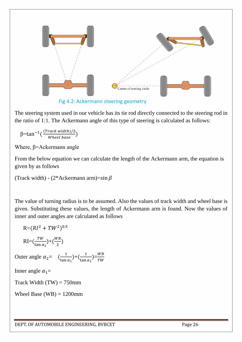
DEPT. OF AUTOMOBILE ENGINEERING, BVBCET Page 26
Fig 4.2: Ackermann steering geometry
The steering system used in our vehicle has its tie rod directly connected to the steering rod in
the ratio of 1:1. The Ackermann angle of this type of steering is calculated as follows:
β=tan−1((𝑇𝑟𝑎𝑐𝑘 𝑤𝑖𝑑𝑡ℎ)/2
𝑊ℎ𝑒𝑒𝑙 𝑏𝑎𝑠𝑒)
Where, β=Ackermann angle
From the below equation we can calculate the length of the Ackermann arm, the equation is
given by as follows
(Track width) - (2*Ackermann arm)=sin 𝛽
The value of turning radius is to be assumed. Also the values of track width and wheel base is
given. Substituting these values, the length of Ackermann arm is found. Now the values of
inner and outer angles are calculated as follows
R=(𝑅𝐼2 + 𝑇𝑊2)0.5
RI=(𝑇𝑊
tan 𝛼2)+(
𝑊𝐵
2)
Outer angle 𝛼2= (1
tan 𝛼1)+(
1
tan 𝛼1)=
𝑊𝐵
𝑇𝑊
Inner angle 𝛼1=
Track Width (TW) = 750mm
Wheel Base (WB) = 1200mm
DEPT. OF AUTOMOBILE ENGINEERING, BVBCET Page 27
Inner Angle = 30 degree
Outer Angle = 23 degree
Turning radius of inner wheel, 𝑅𝑖 = 2400mm
Turning radius of outer wheel, 𝑅𝑜 = 3072mm
Overall turning radius of the whole cart = 2525mm
Ackermann angle = 17.35 degree
4.3.1. Toe in/out setting
Toe setting will affect weight distribution, top speed and cornering response .the more toe in
or out, the slower the top speed becomes due to excessive drag by tires .despite this negative
effect, increase the toe out can have some benefits, for eg. increase toe out will increase initial
cornering response, thus giving the driver a better turn into corner and reducing understeer.
4.3.2. Ackerman
Ackerman steering makes the front tires turn at different rates for eg. the front inside tire will
turn faster than the outside tire when turning into a corner.
4.3.3. Caster
Caster affects the grip of both the front and rear of the cart .it does this by transferring weight
to the opposite rear wheel during cornering. if caster is decreased the kart will be easier to
steer
4.3.4. Camber
Camber is measurement by how far the front are leaning in or out as viewed from the front
of the kart.
4.3.5. Front width
The most common adjustment made to change the handling of kart is by working with its
front track, or front-end width widening the front track will create more of a jacking effect
when the wheels are turned .this will result in more front end grip and quicker turn in.
narrowing the front track will have the opposite effect. This result in slower in and less front
end bite.

DEPT. OF AUTOMOBILE ENGINEERING, BVBCET Page 28
4.4. Steering Parts Creo Parametric 2.0 model:
Fig 4.3: Steering Assembly
Fig 4.4: Tie rod parts

DEPT. OF AUTOMOBILE ENGINEERING, BVBCET Page 29
Fig 4.5: Tie rod and Ackermann arm joint
Fig 4.6: Steering column with drop arm Fig 4.7: Steering wheel

DEPT. OF AUTOMOBILE ENGINEERING, BVBCET Page 30
Fig 4.8: Left stub axle dimensions [all dimensions are in mm]
Fig 4.9: ISO 7379_M10_×_20 Bolt and Nut [all dimensions are in mm]

DEPT. OF AUTOMOBILE ENGINEERING, BVBCET Page 31
These figures below shows how the dimensions have been taken.
Fig 4.10. Inner wheel turns 30O
Fig 4.11. Inner wheel turning radius

DEPT. OF AUTOMOBILE ENGINEERING, BVBCET Page 32
Fig 4.12. Outer wheel angle of turn
Fig 4.13. Outer wheel turning radius

DEPT. OF AUTOMOBILE ENGINEERING, BVBCET Page 33
Fig 4.14. Turning radius of center of kart
Fig 4.15. Turning radius of midpoint of rear axle

DEPT. OF AUTOMOBILE ENGINEERING, BVBCET Page 34
5. TYRES:
5.1. Available tyres
10x4.50-5 KART 3
10x4.50-5 KART2
11x6.00-5 KART1
11x7.10-5 KART 3
11x7.10-5 KART1
10x4.00-5 RAINKART
11x6.00-5 RAINKART
– slick tyre for front use
– slick tyre for front use
– slick tyre for rear use
– slick tyre for rear use
– slick tyre for rear use
– tread pattern tyre for front use
– tread pattern tyre for rear use
Table 5.1. Available Tyres
Requirements for tyres for kart
It should be of small size.
It should have less friction coefficient with respect to road.
It should be durable
Cost of tyres should be minimum.
Radius of tyres should not be more than 10 inch.
Kart tyres have dimension as follows:
SIZE WIDTH (mm)
DIAMETER (mm)
RIM (mm)
10X4.00-5
RAINKART
123 250 4.00x5
10X4.50-5
KART2
133 264 4.50x5
10X4.50-5
KART 3
132 262 4.50x5
11X6.00-5 RAINKART
180 270 6.00x5
11X6.00-5 KART1
184 282 6.00x5
11X7.10-5 KART1
206 282 8.00x5
11X7.10-5
KART3
210 278 8.00x
Table 5.2. Dimensions of tyres available
DEPT. OF AUTOMOBILE ENGINEERING, BVBCET Page 35
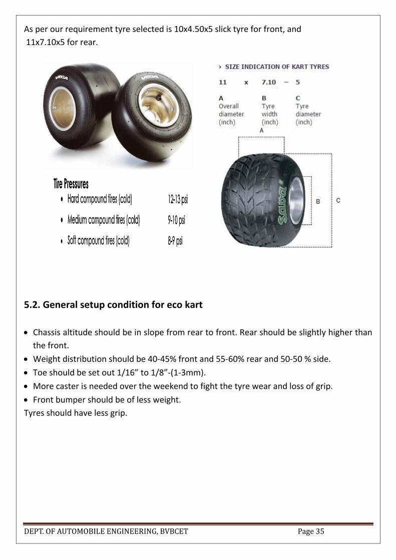
As per our requirement tyre selected is 10x4.50x5 slick tyre for front, and
11x7.10x5 for rear.
5.2. General setup condition for eco kart
Chassis altitude should be in slope from rear to front. Rear should be slightly higher than
the front.
Weight distribution should be 40-45% front and 55-60% rear and 50-50 % side.
Toe should be set out 1/16” to 1/8”-(1-3mm).
More caster is needed over the weekend to fight the tyre wear and loss of grip.
Front bumper should be of less weight.
Tyres should have less grip.

DEPT. OF AUTOMOBILE ENGINEERING, BVBCET Page 36
6. BRAKING SYSTEM:
6.1. ABSTRACT
The purpose of this project is to design a braking system for a SAE Eco-cart vehicle that can
produce adequate braking force to meet competition regulations while being as light weight as
possible. The system should also limit un-sprung weight to help improve manoeuvrability.
Similar products and design of components will be researched for this project. A budget,
timeline, proof of design and testing will also be looked at in this report.
6.2. BRAKE SYSTEM
OBJECTIVE - Design a braking system that can produce more than adequate braking force to
meet SAE Eco-Cart competition regulations while being as light weight as possible. The
system should also limit un-sprung weight to help improve manoeuvrability.
6.3. Braking System
6.3.1 Requirements –
Decelerate in a controlled repeatable manner.
Help maintain constant speed.
Hold vehicle stationary on a flat or on a gradient.
6.3.2 Different condition in which brake system should work properly:-
Slippery, wet and dry roads.
Rough or smooth road.
Split friction surfaces.
Straight line braking or when braking on a curve.
Wet or dry brakes.
New or worn linings.
Laden or unladen vehicle.
Frequent or infrequent applications of short or lengthy duration.
High or low rates of deceleration.
Skilled or unskilled drivers.

DEPT. OF AUTOMOBILE ENGINEERING, BVBCET Page 37
6.4. Brake – Sub systems
Energy source (muscular effort vacuum boost/power braking/surge brakes / spring brakes).
Modulation System (to control brake force).
Transmission systems (brake lines/tubes, brake hoses (flexible tube), rods /livers/cams/cables
etc. Foundation brakes.
6.4.1 System Vehicle parameters required for brake system design
Laden and unladen vehicle mass
Static weight distribution when laden and unladen
Wheelbase
Height of center of gravity when laden and unladen
Maximum vehicle speed
Tyre and rim size
Vehicle function
6.4.2 Braking standards Brake System Components & Configurations
Pedal assembly
Brake booster to reduce manual pressure ,vacuum booster(uses negative pressure in
intake manifold
Master cylinder -initiates & control braking -two separate braking circuits (primary &
secondary) -2 pistons in the same cylinder - If one system has a leak , the other takes
care
Regulating valves -when load transferred to the front , braking at rear need to be
reduced

DEPT. OF AUTOMOBILE ENGINEERING, BVBCET Page 38
Fig 6.1: brake system design.
6.5. BRAKING SYSTEM DESIGN – The brake system was designed to the rules,
restrictions, and requirements provided by the SAE to ensure the vehicle can decelerate and
stop within a reasonable distance. The brake system was designed with a budget of 8000 rupees
and 10kg (98 N) of pressure applied by driver.
6.5.1 MASTER CYLINDER – The master cylinders play a large part in the design phase. In
order to satisfy the deceleration goal of 0.9 g the master cylinders would have to be able to
transfer the correct amount of pressure to the brake caliper pistons. The master cylinders
chosen to do so are the rear master cylinders for a Yamaha r15 disk brake. With a 0.75 in.
bore, they would provide more than enough pressure given an average 40 kg(392N ) driver
input force by a 4:1 pedal ratio(lever arm ratio for master cylinder input force). The average
10 kg driver input force was determined thru literature survey by the team and the 4:1 pedal
ratio was decided based off calculations and pedal configuration and verified by the average
driver foot size.
Fig 6.2: brake master cylinder.

DEPT. OF AUTOMOBILE ENGINEERING, BVBCET Page 39
6.5.2 BRAKE ROTORS – The brake rotors are a part of the system that can be optimized
to gain performance as well as limit weight. The rotors chosen for our application is Yamaha
r15 disk brake “1CKF582W0000”. Because we are using the spindles and callipers from the
disk brake kit this match the hubs and bearing carrier selected by the chassis design
requirement.
Fig 6.3: brake disc rotor.
6.5.3 BRAKE PEDAL – The brake pedal was designed to accommodate the required pedal
ratio. The minimum ratio required to generate required force to stop the vehicle is 3.4:1 with
a driver input force of 98N. In order to make the brake pedal the correct length for the average
foot size of our drivers the ratio was increased to 4:1 (8 inch pedal). This will allow us to
require even less driver input force than the minimum experimentally measured. With the
pedal ratio of 4:1 the new minimum required driver input force to stop the vehicle becomes
40kg. Not only will this help us stop quicker but this will also help prevent driver fatigue
during an endurance race. The brake pedal will be designed out of 6061-T6 aluminium to keep
weight down while still having more than enough strength.

DEPT. OF AUTOMOBILE ENGINEERING, BVBCET Page 40
Fig 6.3: brake pedal.

DEPT. OF AUTOMOBILE ENGINEERING, BVBCET Page 41
Table 6.1: list of popular mass produced brake master cylinder along with diameter and their areas.
6.5.4 Brake fluid The three main types of brake fluid now available are DOT3, DOT4 and DOT5. DOT3 and
DOT4 are glycol-based fluids, and DOT5 is silicon-based. The main difference is that DOT3
and DOT4 absorb water, while DOT5 doesn't.
One of the important characteristics of brake fluid is its boiling point. Hydraulic systems rely
on an incompressible fluid to transmit force. Liquids are generally incompressible while gases
are compressible. If the brake fluid boils (becomes a gas), it will lose most of its ability to
transmit force. This may partially or completely disable the brakes.
As a DOT3 or DOT4 brake fluid absorbs water, its boiling point decreases. It can absorb water
from the air, which is why we should avoid opening your car's brake fluid reservoir. For the
same reason, we should always keep containers of brake fluid tightly sealed. DOT5 fluid does
not absorb water. This means the boiling point will remain relatively stable, but it also means
that any water that does get into your brake system will tend to form pure water pockets, which
could cause brake corrosion.

DEPT. OF AUTOMOBILE ENGINEERING, BVBCET Page 42
Two other important things about brake fluid: DOT3 and DOT4 eat paint, . Also, none of the
different types of brake fluid should be mixed. They can react badly with each other and
corrode your brake system.
Table 6.2: brake system assembly parts along with cost.

DEPT. OF AUTOMOBILE ENGINEERING, BVBCET Page 43
6.6. Kinematics of braking
Graph 6.1: deceleration vs time graph.
Graph 6.2: velocity vs time graph.
Graph 6.3: displacement vs time graph.

DEPT. OF AUTOMOBILE ENGINEERING, BVBCET Page 44
6.6.1 Assumptions
Instantaneous change in declaration
no driver reaction time
no system response time
no deceleration rise time
no release time
6.6.2 Typical Measured Deceleration time-history
Driver reaction time t0 -t1 -driver responds & move his foot to the pedal.
Initial system response time t1 -t2 -up to start of braking force at tyre.
Deceleration rise time -time to reach peak deceleration t2 -t3.
Braking time t 3 - t 4 -till vehicle stops.
Release time t 4 - t 5 -brake release starts stopping timeto end of brake force t 0 - t 4
/t 5.
Braking time t 1 - t 4 /t 5.
Graph 6.4: declaration time behaviour for braking.
6.6.3 Retardation force
Primarily foundation braking
Rolling resistance (=0.01g).
Aerodynamic drag (proportional to at high speed) =0.03g.
Drive train drag - can contribute to the braking effort or use brake torque.
6.6.4 Load transfer during braking
• A variable brake effort ratio is required to provide ideal braking.
• Factors
Change in vehicle weight;
Change in weight distribution;

DEPT. OF AUTOMOBILE ENGINEERING, BVBCET Page 45
The effect of gradients (positive and negative);
Cornering, (also lateral forces);
Varying road surfaces and weather conditions;
Split friction surfaces where the coefficient of adhesion changes from front to rear.
6.6.5 Brake calculation
6.7. The Brake Pedal
The brake pedal is a simple lever. The fulcrum is at the top of the pedal arm, the input is at
the opposite end, and the output is somewhere in between. For example, a driver input force
of 98N is multiplied by a 4:1 ratio into 392N of output force. This output force becomes the
input force for the power brake unit or booster. The travel of the driver’s foot will of course
be 4 times the travel of the booster input pushrod. Pedal ratios on most vehicles today vary
between 3:1 and 5:1.
6.8. VEHICLE DYNAMICS
6.8.1 Static Axle Load Distribution
Ms/M =¥
Ms = static rear axle load (kg)
M=total vehicle mass (kg)
¥= static axle load distribution
Taking maximum total vehicle mass 140 kg
60%of total weight as static rear axle loads 84kg
Static axel load distribution is =.6
6.8.2 Relative Centre of Gravity Height
H/Wb = X
h = vertical distance from C to G to ground on the level (m)
Wb = wheelbase (m)
X= relative center of gravity height
Vertical distance from c of g to ground is 10 inch = .254 m

DEPT. OF AUTOMOBILE ENGINEERING, BVBCET Page 46
Wheelbase is 1150 mm= 1.15 m
Therefore, relative center of gravity height = .22
6.8.3 Dynamic Axle Loads (Two Axle Vehicles Only)
The changes in axle loads during braking bear no relationship to which axles are braked.
They only depend on the static laden conditions and the deceleration.
((1 - ¥) + (X.a)).M = Mfdyn
a = deceleration (g units)
M = total vehicle mass (kg)
Mfdyn = dynamic front axle load (kg)
Dynamic rear axle load =83.72 kg
6.8.3 STOPPING THE VEHICLE
Braking Force
The total braking force required can simply be calculated using Newton’s Second Law
M=140 kg
A= .9 g
G=9.81m/sec2
Total braking force =1236.06 N

DEPT. OF AUTOMOBILE ENGINEERING, BVBCET Page 47
6.8.4 Wheel Lock
The braking force can only be generated if the wheel does not lock because the friction of
a sliding wheel is much lower than a rotating one. The maximum braking force possible
on any particular axle before wheel lock is given by:
Dynamic axle mass =83.72kg
G=9.81m/s2
Coefficient of friction b/w road and tyre= 0.7
Total possible braking force on axel =574.90N
6.8.5 Brake Torque
Braking force for the axel= 574.90N
Static laden radius of tyre 10 inch =.254m
Speed ratio =1
Brake torque = 146.02 Nm
6.8.6 FOUNDATION BRAKE
Disc Effective Radius
The effective radius (torque radius) of a brake disc is the centre of the brake pads by area.
For dry discs it is assumed to be:
DEPT. OF AUTOMOBILE ENGINEERING, BVBCET Page 48
D=.220m
D=.170m
Effective radius =.09m
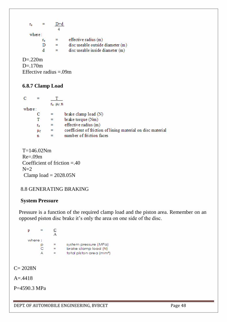
6.8.7 Clamp Load
T=146.02Nm
Re=.09m
Coefficient of friction =.40
N=2
Clamp load = 2028.05N
8.8 GENERATING BRAKING
System Pressure
Pressure is a function of the required clamp load and the piston area. Remember on an
opposed piston disc brake it’s only the area on one side of the disc.
C= 2028N
A=.4418
P=4590.3 MPa

DEPT. OF AUTOMOBILE ENGINEERING, BVBCET Page 49
6.8.9 Calculating Master Cylinder Line Pressure
Pressure = (Leg force on the pedal) x (Pedal Ratio) divided by (Master Cylinder Piston Area).
Pressure =484 psi
Stopping distance
Work done =force x distance
K.E= ½ x mass x velocity2
Mass of car 140 kg
Velocity =11.11m/s
Braking force= 2028N
K.E= ½ x 140x11.11x 11.11
=8640.27j
W.D=K.E
8640=2028 x stopping distance
S.D= 4.26m.
Braking efficiency =brake is 100% efficient. Producing deceleration equal to 9.81m/s2.
Considering reaction time of 0.25 sec.
Thinking distance =.25x 11.11=2.77m
Deceleration = 1x 9.81=-9.81m/s2
Stopping distance = 4.26+2.77
= 7.03mts

DEPT. OF AUTOMOBILE ENGINEERING, BVBCET Page 50
Fig 6.5: Thermal
Maximum heat flux is 3.7e-13 W/mm2
Minimum heat flux is 8.1e-16 W/mm2

DEPT. OF AUTOMOBILE ENGINEERING, BVBCET Page 51
Fig 6.6: Stress
Maximum Stress is 0.26 MPa
Fig 6.7: Strain
Maximum strain is 1.32e-6
Fig 6.8: Total Deformation
Maximum Deformation is 1.54e-5 mm

DEPT. OF AUTOMOBILE ENGINEERING, BVBCET Page 52
7. FRAME:
7.1. Introduction
Here is a discussion about the design of the Frame. Frame is one of the most important part
of a vehicle as it is responsible to provide the driver safety and each and every component of
the vehicle will be mounted on it. Even it responsible for weight distribution hence stability of
the vehicle. The chassis design is crucial to the success of the project because if the chassis
fails, that puts the Baja and the driver at tremendous risk.
7.2. Objectives:
Our objectives in designing an Eco Kart frame are:
Providing ultimate level of safety for absorbing all the impact and protect the driver
Be aesthetically pleasing
Lightweight
Easy to sit and leave the seat
Simple Design for Easy Manufacture
7.3. Design of frame:
For designing Eco Kart frame some parameters are considered. They are:
7.3.1. Safety:
Safety is the top priority in the design of the frame. Most of the SAE rules pertain to safety.
The selected material has been chosen is strong enough to sustain all types of load which are
supposed be applied over it. And the diameter and thickness of primary and secondary
members must be enough with some factor of safety.
Triangulation has been done to the places where the loads are more which are proved to more
efficient than rectangular members.
Shock absorbing bumper is used, where spring is used which increases comfort while small
impact.
7.3.2. Ergonomics and Comfort:
For designing and deciding the dimension we first considered the space needed by the driver
to seat comfortably. To improve ergonomics, driver is provided with more legroom. And we
have taken care that driver of 5’6” height to 6’2” can be seated without compromising with
comfort.
DEPT. OF AUTOMOBILE ENGINEERING, BVBCET Page 53
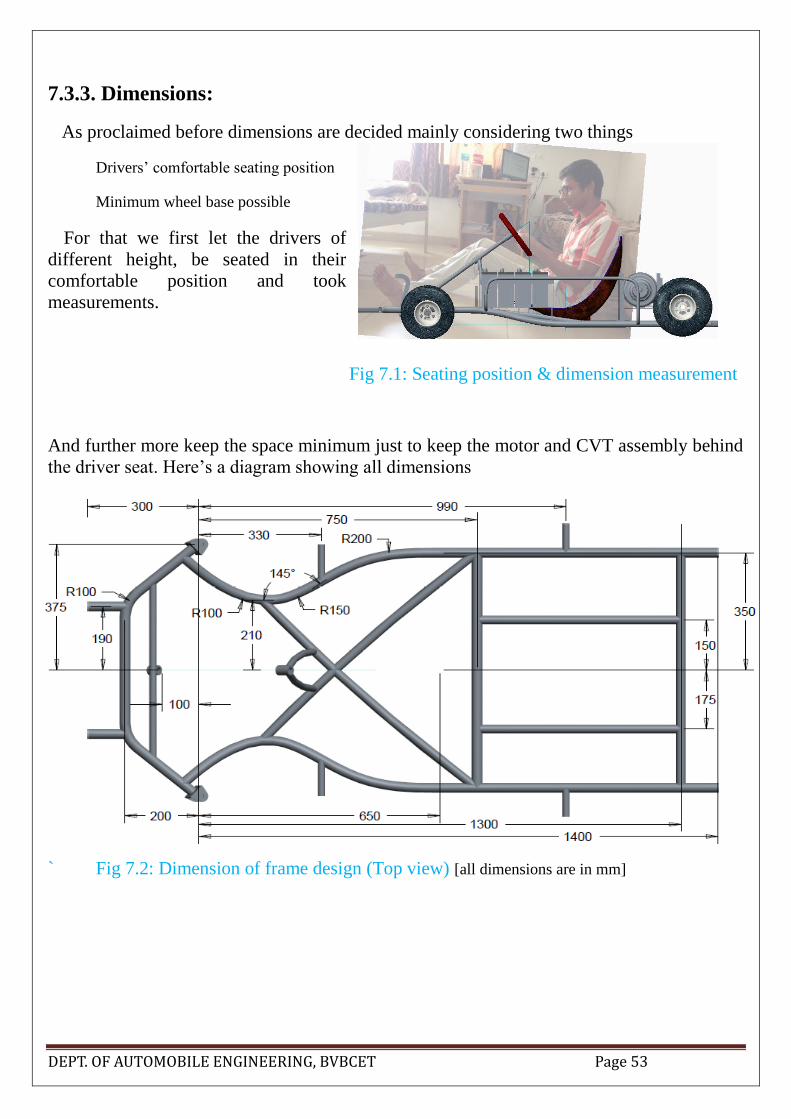
7.3.3. Dimensions:
As proclaimed before dimensions are decided mainly considering two things
Drivers’ comfortable seating position
Minimum wheel base possible
For that we first let the drivers of
different height, be seated in their
comfortable position and took
measurements.
Fig 7.1: Seating position & dimension measurement
And further more keep the space minimum just to keep the motor and CVT assembly behind
the driver seat. Here’s a diagram showing all dimensions
` Fig 7.2: Dimension of frame design (Top view) [all dimensions are in mm]

DEPT. OF AUTOMOBILE ENGINEERING, BVBCET Page 54
Fig 7.3: Dimension of frame design (Side view) [all dimensions are in mm]
7.3.4. Material Selection:
Material selection impacts both the weight of the frame, its rigidity, and its safety.
Vehicle is small kart of less weight, with less speed of 40 kmph, and supposed to run on smooth
road, considering this we have set our benchmark maximum strength will not be more than
SAE BAJA frame. The rules specify the bending stiffness as no less than that of a 1in diameter
steel tube made out of AISI 1018 alloy with a 0.12 in wall thickness.
There are lots of materials which are used now a days. Steel is mostly used everywhere,
following it aluminum and even carbon fibers.
Carbon fiber does not come in our budget, and also not available here easily, so we firstly
rejected it.
And aluminum has density 3times less than that of steel, hence increasing strength to weight
ratio a lot, really a tempting one. But it costs more, and comes with unnecessary complication
for fabrication. We need to take special care for attaching each and every mere thing.
Where working with steel is very easier compared to all other material. On steel we can mount
each part easily by simple welding processes. It is the most promising one. Price is also less,
and easily available. And a little heavier chassis may show better results in weight distribution.
So we decided to use steel for frame. But in some other parts, where it is convenience we will
use aluminum also.
But there are a few thousands types of steel available. We faced it very difficult for choosing
among them. We need to find best strength to weight ratio and also other favorable properties
like ease of fabrication.

DEPT. OF AUTOMOBILE ENGINEERING, BVBCET Page 55
Here is comparison of the properties of some materials
Table 7.1: Properties of Materials
From these materials list we have chosen AISI 1080 (annealed) to make frame. It is available
in near to our locality. Which has good strength to weight ratio.
AISI 1080 is a Standard grade Carbon Steel. It is composed of (in weight percentage) 0.75-
0.88% Carbon (C), 0.60-0.90% Manganese (Mn), 0.04 %( max) Phosphorus (P), 0.05 %( max)
Sulfur (S), and the base metal Iron (Fe). Other designations of AISI 1080 carbon steel include
UNS G10800 and AISI 1080.
Typical chemical composition of AISI 1080
C: 0.60-0.90
Si: 0.60
Mn: 0.45/0.70
S: 0.05
P: 0.04
Ni: 1.30/1.70
Properties:
Density: 7850 kg/m3
Elastic modulus: 205 GPa
Poisson’s ratio: 0.285
Yield strength: 390 MPa
Tensile strength: 650 MPa
Steel Yield strength(MPa) Tensile strength(MPa) Density (kg/m3)
1018 365 435 7870
1020 295 395 7870
1030 340 460 7870
1080 390 635 7870
4130 460 560 7850
4340 470 740 7850

DEPT. OF AUTOMOBILE ENGINEERING, BVBCET Page 56
From table 1 we can chose best suited material for our design. But, there are so many
combination of standard external diameter with wall thickness available.
Table 7.2: Tubes of available sizes.
We need to choose the best in our way.
Bending Stiffness (M) = EI
Where,
E: Elastic modulus [205000MPa]
I: Second moment of inertia (mm4)
The best way to increase I while decreasing area is to increase outer diameter and decrease
wall thickness. The minimum wall thickness we are recommending to be 1.6mm as anything
less than that is very difficult to weld.
And to keep the weight minimum we need take minimum outer diameter, which just can bear
the load on it in all driving condition.
Choosing correct outer dia was like a iteration. First we choose 25.4mm, then found it not
satisfactory and decided to use 31.8. Then after analysis we found 28.6mm tube also holds
good and we finalized it. Only one tube on which most of the drivers weight directly affects
we are providing wall thickness of 2mm.

DEPT. OF AUTOMOBILE ENGINEERING, BVBCET Page 57
M = 205000 × 𝜋
64 × (28.64 – (28.6 – 3.2)4)
= 254417772
I = 12410.62 mm4
Bending strength, B =
Where, Sy = 390 MPa
C = distance of extreme fiber from neutral axis = 14.3mm
B = 338471 Nmm
= 338 Nm
It is enough because it achieved even the BAJA rule which was our bench mark for highest
strength.
7.3.5. Structural Considerations:
Using a bend instead of welding the tubes produces a sturdier frame. Tubes may bended as
much of the frame as possible.
Circles or semicircles are good shapes to work with since they lack corners. Corners tend to
act as stress risers. Welding involves joining two or more metal parts together. When this is
done, it creates a corner or an edge, where stress concentrations can occur.
Furthermore, bending one is not joining two separate bodies so the end result is tougher as
the weld is something that is more likely to fail. Bending instead of welding, the loads are
distributed more evenly improving the rigidity of the frame.
In areas of the frame where welds are needed, there three tubes may be joined and that join
together to create a triangle. Triangle is a good shape from a structural standpoint as it is the
next shape with the fewest corners. A triangle less likely to twist than a rectangle or other
polygon. Another advantage of the triangle is that is can be slanted and this increases the
likeliness of something to deflect off of it when it is hit.

DEPT. OF AUTOMOBILE ENGINEERING, BVBCET Page 58
7.3.6. Accessibility:
As a go kart is not having body works much, and all the parts are open, all the component are
quite easily accessible by default.
Still for the driver comfortable work all the parts are spaced such a way that from his seating
position he can extend his arms to the all components he may need to.
7.3.7. Manufacturability:
Simplicity in the design is important in order to make it easier to manufacture. However, due
to a combination of the material choice and bend usage instead of welds in certain locations,
the overall manufacturability is negatively impacted. The steel has a tendency to wrinkle when
bending because of its high stiffness and the relative thinness of the walls of the tubes. To
improve manufacturability, only the tubes having less relative thickness may be blended.
But overall it is easier than aluminum and other materials.
Welding: Tungsten inert gas, or TIG welding is most time consuming type of welding
process. But it is too costly and not available everywhere. And for critical joints it is difficult
to do.
So for us metal inert gas, or MIG welding will be helpful. And it is cheaper and easier than
TIG welding. This process is very precise and suitable for ECO KART frame as it creates no
spatter or slag and is the cleaner type of welding process because it requires no clean up.
However, it requires a lot of pre-weld prepping and meticulous cleaning of the material.
7.3.8. Body & Floor pan:
Modern racecar bodies are usually made out of the lightest materials with only enough
strength to accomplish the task of holding their shape for aerodynamic performance during the
race. The best composite material would be carbon fiber. However, carbon fiber material is
not a feasible idea because of its price and unavailability.
We need body works just to make the kart look good and for a little aero dynamic effect. It
should be little strong just to be able to withstand the aero dynamic resistances. We are fixing
foam sheet with fasteners and glue as body of our vehicle
The bottom floor pan will be made from a sheet of aluminum having thickness of 0.035”,
for allowing the driver to keep his feet comfortably on the frame.
DEPT. OF AUTOMOBILE ENGINEERING, BVBCET Page 59
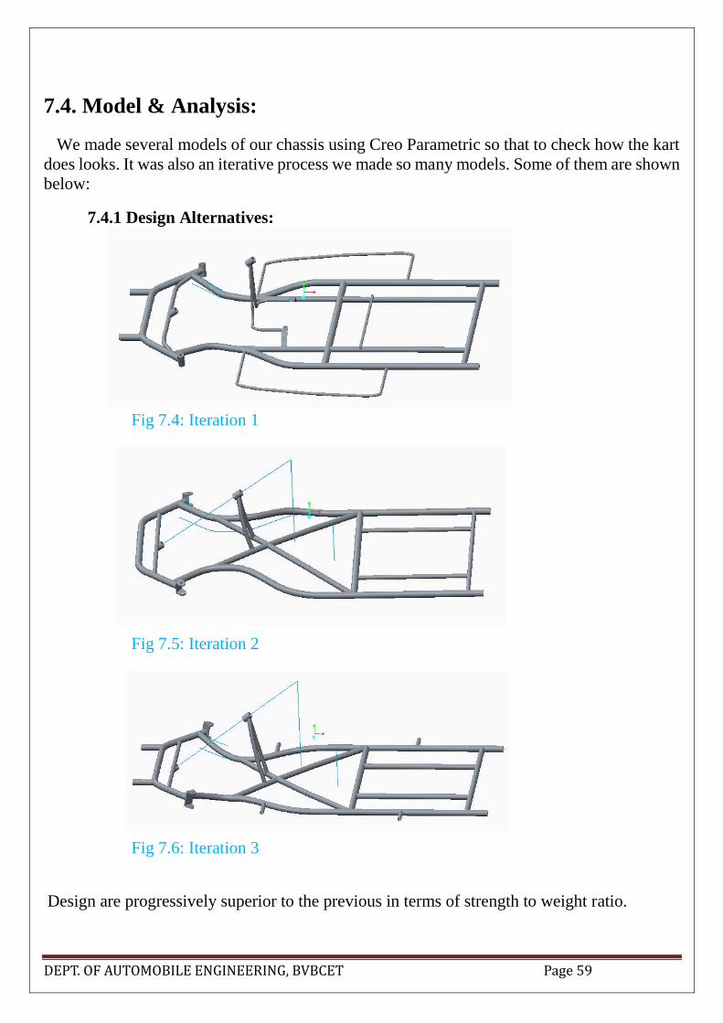
7.4. Model & Analysis:
We made several models of our chassis using Creo Parametric so that to check how the kart
does looks. It was also an iterative process we made so many models. Some of them are shown
below:
7.4.1 Design Alternatives:
Fig 7.4: Iteration 1
Fig 7.5: Iteration 2
Fig 7.6: Iteration 3
Design are progressively superior to the previous in terms of strength to weight ratio.
DEPT. OF AUTOMOBILE ENGINEERING, BVBCET Page 60
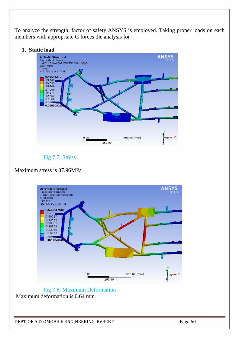
To analyze the strength, factor of safety ANSYS is employed. Taking proper loads on each
members with appropriate G forces the analysis for
1. Static load
Fig 7.7: Stress
Maximum stress is 37.96MPa
Fig 7.8: Maximum Deformation
Maximum deformation is 0.64 mm

DEPT. OF AUTOMOBILE ENGINEERING, BVBCET Page 61
Fig 7.9: Factor of Safety
Minimum factor of safety is 2.27
2. Frontal Impact
Fig 7.10: forces acting while an impact
Applying 4g force impact analysis is done. The results are shown below:

DEPT. OF AUTOMOBILE ENGINEERING, BVBCET Page 62
Fig 7.11: Stress
The maximum stress is 33.434 MPa
Fig 7.12: Total deformation
Maximum deformation is 0.557 mm

DEPT. OF AUTOMOBILE ENGINEERING, BVBCET Page 63
Fig 7.13: Factor of safety
The minimum Factor safety is 2.57.

DEPT. OF AUTOMOBILE ENGINEERING, BVBCET Page 64
8. Assembly & Mounting:
All the other components are spaced on with so many things in mind like, because it has
influence on ergonomics, aesthetics, weight distribution and accessibility.
We decided the proper space for the components and made another small frame according to
the dimensions of the components and provide proper mounts for them.
We trying to make them to do multiple task, like instead of making separate mountings for
each parts we are making them the sub frame to hold more than one components which are
comfortable with each other. For eg. On the side cage made for battery we are attaching brake
master cylinder. This idea helped us to decreasing weight a lot and complexity and cost as
well.
8.1. Rods & Fasteners: For assembly we have used some materials and fasteners, here’s
a list of some most used things.
1. Shape rod for making cage for battery, stand for motor, CVT, and other
components
2. Shape rod for making sub frame on main frame to keep and mount all
other components
3. Nuts & bolts:
8.2. Mounts:
8.2.1. Steering system mount:
On the high lightened portion steering column will
be place through some bushes, so that it can be turned
easily.

DEPT. OF AUTOMOBILE ENGINEERING, BVBCET Page 65
8.2.2. Front stub axle mount:
C clamp made of iron plate of 5 mm thickness is used. Iron
can be easily joined to the chassis by means of any welding
processes, that’s why in spite of heavy weight we are using it.
8.2.3. Electrical system:
Display for showing battery status (with kill switch) is
mounted on the stand for steering column,on a L shape rod. It
will be simply attached with the help of tape and adhessives so
that it can be easily removed when needed.
The figure shows the cage made of L-shape rod for battery
and the small box for main switch, which is spaced on the left
side of the driver seat.
Motor controller and Battery management system is placed
on a tray on the left side of the driver seat.

DEPT. OF AUTOMOBILE ENGINEERING, BVBCET Page 66
8.2.4. Seat:
The back portion of the seat is kept on the tube which goes
across the frame, which takes most of the driver’s weight.
On those cross tubes there are to L-shape small stand which
supports the seat from the front. And seat is fitted on those
with suitable nuts and bolts.
8.2.5. Fire extinguisher:
Fire extinguisher is placed on the right of the driver
seat. On the joint of tubes of main frame creates a tri arm
shape on those three arms we made stand with L-shape
rods on which fire extinguisher can easily seat. This idea
reduces complexity and weight. And driver can easily
remove it from its place and use it in minimum possible
time.
8.2.6. Power unit:
Behind the driver seat stand are made for motor and cvt. The L-
shape rods are used. On which motor will be place by means of
screws.
The power shaft is mounted on the
frame by four bearings and bearing
holders on it. The bearing holder

DEPT. OF AUTOMOBILE ENGINEERING, BVBCET Page 67
gives the power shaft required height, and holds it strongly to the chassis.
8.2.7. Braking system:
Brake master cylinder is
attached on a rod of the cage
for battery. In this way we are
making the mounts to
perform multifunction. It
reduces weight and implied
costs also.
8.2.8. Front and rear bumper:
On the front and rear of the frame tubes
are kept open through which the front and
rear bumper will be connected, which is
removable, so if any damage appears on
bumper it is easily removed, repaired
then again fitted.
DEPT. OF AUTOMOBILE ENGINEERING, BVBCET Page 68
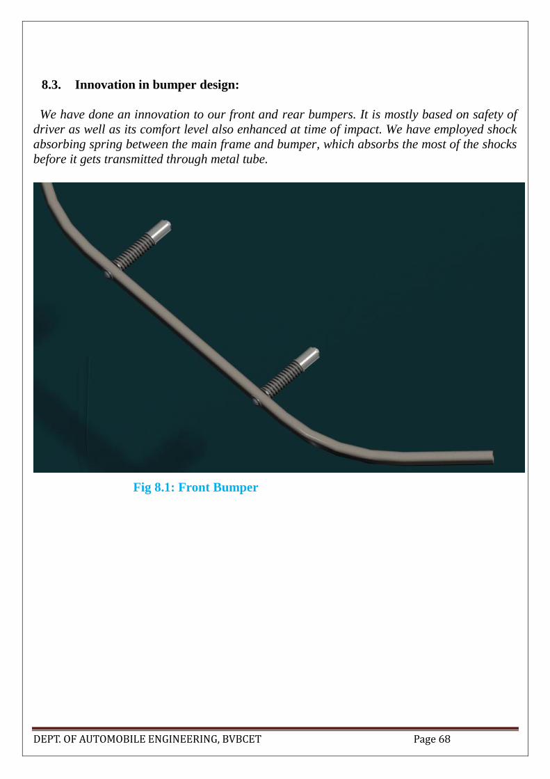
8.3. Innovation in bumper design:
We have done an innovation to our front and rear bumpers. It is mostly based on safety of
driver as well as its comfort level also enhanced at time of impact. We have employed shock
absorbing spring between the main frame and bumper, which absorbs the most of the shocks
before it gets transmitted through metal tube.
Fig 8.1: Front Bumper
DEPT. OF AUTOMOBILE ENGINEERING, BVBCET Page 69
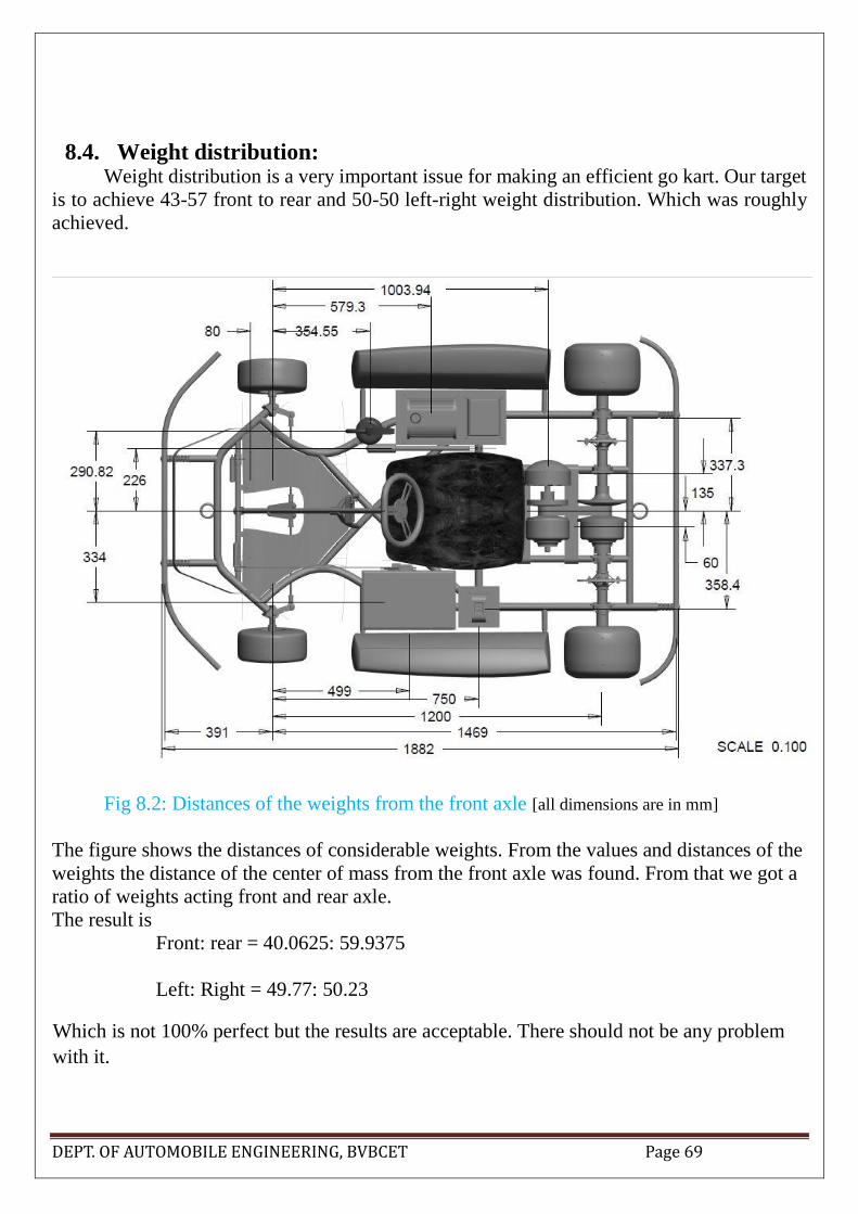
8.4. Weight distribution: Weight distribution is a very important issue for making an efficient go kart. Our target
is to achieve 43-57 front to rear and 50-50 left-right weight distribution. Which was roughly
achieved.
Fig 8.2: Distances of the weights from the front axle [all dimensions are in mm]
The figure shows the distances of considerable weights. From the values and distances of the
weights the distance of the center of mass from the front axle was found. From that we got a
ratio of weights acting front and rear axle.
The result is
Front: rear = 40.0625: 59.9375
Left: Right = 49.77: 50.23
Which is not 100% perfect but the results are acceptable. There should not be any problem
with it.

DEPT. OF AUTOMOBILE ENGINEERING, BVBCET Page 70
9. REFERENCES
1. Multibody Systems Approach to Vehicle Dynamics –by Michael Blundell & Damian
Harty
2. An Introduction to Modern Vehicle Design - Edited by Julian Happian-Smith
3. (IJISME) “An Innovative Energy Efficient Automobile Design” ISSN: 2319-6386,
Volume-2 Issue-10, September 2014
4. (IJAET) “DESIGN AND ANALYSIS OF HYBRID GO-KART” E-ISSN 0976-3945
5. “SHELL ECO-MARATHON Final Report”-Florida International University;
February 20, 2012
6. (IJITEE) “Optimization of Chassis of an All-Terrain Vehicle” ISSN: 2278-3075,
Volume-2, Issue-2, January 2013
7. 2013-2014 WPI SAE Baja Vehicle; Date: April 10, 2014
8. (IJERA) “Design And Fabrication Of Environment Friendly Kart”; ISSN: 2248-9622
13th-14th March 2014
9. DESIGN REPORT OF THE ECOKART VEHICLE - BY HAMMER HEADS
TEAM
10. Ackermann steering geometry-Wikipedia, the free encyclopedia
11. The S-90 Go-Kart; Alternative Design Report 1-By James Paolino, Alexander
Jadczak, Eric Leknes, and Tarek Tantawy; Sean Stenglein. NSF Projects; Ashford,
CT. 860-429-1059
12. Union College SAE Baja Vehicle Design Report- by Matthew Beenen, Jon Wilson
and Ned Lincoln

DEPT. OF AUTOMOBILE ENGINEERING, BVBCET Page 71

DEPT. OF AUTOMOBILE ENGINEERING, BVBCET Page 72