Embed Size (px)
Citation preview

Operator’s Manual
SAE-400 ®
Register your machine: www.lincolnelectric.com/register
Authorized Service and Distributor Locator: www.lincolnelectric.com/locator
IM10027-C | Issue D ate Aug-15
© Lincoln Global, Inc. All Rights Reserved.
For use with machines having Code Numbers:
11605, 11807, 11966, 12311
Save for future reference
Date Purchased
Code: (ex: 10859)
Serial: (ex: U1060512345)
THANK YOU FOR SELECTING A QUALITY PRODUCT BY LINCOLN ELEC TRIC.
PLEASE EXAMINE CARTON AND EQUIPMENT FORDAMAGE IMMEDIATELY
When this equipment is shipped, title passes to the purchaserupon receipt by the carrier. Consequently, claims for materialdamaged in shipment must be made by the purchaser against thetransportation company at the time the shipment is received.
SAFETY DEPENDS ON YOU
Lincoln arc welding and cutting equipment is designed and builtwith safety in mind. However, your overall safety can be increasedby proper installation ... and thoughtful operation on your part. DO NOT INSTALL, OPERATE OR REPAIR THIS EQUIPMENT WITHOUT READING THIS MANUAL AND THE SAFETYPRECAUTIONS CONTAINED THROUGHOUT. And, most importantly,think before you act and be careful.
This statement appears where the information must be followedexactly to avoid serious personal injury or loss of life.
This statement appears where the information must be followedto avoid minor personal injury or damage to this equipment.
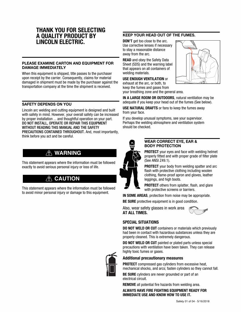
KEEP YOUR HEAD OUT OF THE FUMES.
DON’T get too close to the arc.Use corrective lenses if necessaryto stay a reasonable distanceaway from the arc.
READ and obey the Safety DataSheet (SDS) and the warning labelthat appears on all containers ofwelding materials.
USE ENOUGH VENTILATION orexhaust at the arc, or both, tokeep the fumes and gases from your breathing zone and the general area.
IN A LARGE ROOM OR OUTDOORS, natural ventilation may beadequate if you keep your head out of the fumes (See below).
USE NATURAL DRAFTS or fans to keep the fumes away from your face.
If you de velop unusual symptoms, see your supervisor. Perhaps the welding atmosphere and ventilation system should be checked.
WEAR CORRECT EYE, EAR & BODY PROTECTION
PROTECT your eyes and face with welding helmetproperly fitted and with proper grade of filter plate(See ANSI Z49.1).
PROTECT your body from welding spatter and arcflash with protective clothing including woolenclothing, flame-proof apron and gloves, leatherleggings, and high boots.
PROTECT others from splatter, flash, and glarewith protective screens or barriers.
IN SOME AREAS, protection from noise may be appropriate.
BE SURE protective equipment is in good condition.
Also, wear safety glasses in work areaAT ALL TIMES.
SPECIAL SITUATIONS
DO NOT WELD OR CUT containers or materials which previouslyhad been in contact with hazardous substances unless they areproperly cleaned. This is extremely dangerous.
DO NOT WELD OR CUT painted or plated parts unless specialprecautions with ventilation have been taken. They can releasehighly toxic fumes or gases.
Additional precautionary measures
PROTECT compressed gas cylinders from excessive heat,mechanical shocks, and arcs; fasten cylinders so they cannot fall.
BE SURE cylinders are never grounded or part of an electrical circuit.
REMOVE all potential fire hazards from welding area.
ALWAYS HAVE FIRE FIGHTING EQUIPMENT READY FORIMMEDIATE USE AND KNOW HOW TO USE IT.
WARNING
CAUTION
Safety 01 of 04 - 5/16/2018
SECTION A:WARNINGS
CALIFORNIA PROPOSITION 65 WARNINGS
WARNING: Breathing diesel engine exhaustexposes you to chemicals known to the Stateof California to cause cancer and birth defects,
or other reproductive harm.• Always start and operate the engine in a
well-ventilated area.• If in an exposed area, vent the exhaust to the outside.• Do not modify or tamper with the exhaust system. • Do not idle the engine except as necessary.For more information go to www.P65 warnings.ca.gov/diesel
WARNING: This product, when used for welding or
cutting, produces fumes or gases which contain
chemicals known to the State of California to cause
birth defects and, in some cases, cancer. (California
Health & Safety Code § 25249.5 et seq.)
WARNING: Cancer and Reproductive Harm
www.P65warnings.ca.gov
ARC WELDING CAN BE HAZARDOUS. PROTECTYOURSELF AND OTHERS FROM POSSIBLE SERIOUSINJURY OR DEATH. KEEP CHILDREN AWAY. PACEMAKER WEARERS SHOULD CONSULT WITHTHEIR DOCTOR BEFORE OPERATING.
Read and understand the following safety highlights. Foradditional safety information, it is strongly recommended that you purchase a copy of “Safety in Welding & Cutting - ANSI Standard Z49.1” from the American Welding Society, P.O. Box 351040, Miami, Florida 33135 or CSA Standard W117.2-1974. A Free copy of “Arc Welding Safety” booklet E205 is available from the Lincoln Electric Company, 22801 St. Clair Avenue, Cleveland, Ohio 44117-1199.
BE SURE THAT ALL INSTALLATION, OPERATION,MAINTENANCE AND REPAIR PROCEDURES AREPERFORMED ONLY BY QUALIFIED INDIVIDUALS.
FOR ENGINE POWEREDEQUIPMENT.
1.a. Turn the engine off before troubleshootingand maintenance work unless themaintenance work requires it to be running.
1.b. Operate engines in open, well-ventilated areas or vent the engineexhaust fumes outdoors.
1.c. Do not add the fuel near an open flame weldingarc or when the engine is running. Stop theengine and allow it to cool before refueling toprevent spilled fuel from vaporizing on contact
with hot engine parts and igniting. Do not spill fuel when fillingtank. If fuel is spilled, wipe it up and do not start engine untilfumes have been eliminated.
1.d. Keep all equipment safety guards, covers and devices in position and in good repair.Keep hands, hair, clothing and tools away from V-belts, gears, fans and all other moving parts when starting, operating orrepairing equipment.
1.e. In some cases it may be necessary to remove safety guards toperform required maintenance. Remove guards only whennecessary and replace them when the maintenance requiringtheir removal is complete. Always use the greatest care whenworking near moving parts.
1.f. Do not put your hands near the engine fan. Do not attempt tooverride the governor or idler by pushing on the throttle controlrods while the engine is running.
1.g. To prevent accidentally starting gasoline engines while turningthe engine or welding generator during maintenance work,disconnect the spark plug wires, distributor cap or magneto wireas appropriate.
1.h. To avoid scalding, do not remove the radiatorpressure cap when the engine is hot.
ELECTRIC ANDMAGNETIC FIELDS MAYBE DANGEROUS
2.a. Electric current flowing through any conductorcauses localized Electric and Magnetic Fields (EMF). Welding current creates EMF fields around welding cables and welding machines
2.b. EMF fields may interfere with some pacemakers, and welders having a pacemaker should consult their physicianbefore welding.
2.c. Exposure to EMF fields in welding may have other health effectswhich are now not known.
2.d. All welders should use the following procedures in order tominimize exposure to EMF fields from the welding circuit:
2.d.1. Route the electrode and work cables together - Securethem with tape when possible.
2.d.2. Never coil the electrode lead around your body.
2.d.3. Do not place your body between the electrode and workcables. If the electrode cable is on your right side, thework cable should also be on your right side.
2.d.4. Connect the work cable to the workpiece as close as pos-sible to the area being welded.
2.d.5. Do not work next to welding power source.
SAFETY
Safety 02 of 04 - 5/16/2018
ELECTRIC SHOCK CAN KILL.
3.a. The electrode and work (or ground) circuits areelectrically “hot” when the welder is on. Donot touch these “hot” parts with your bare skin or wet clothing.Wear dry, hole-free gloves to insulate hands.
3.b. Insulate yourself from work and ground using dry insulation.Make certain the insulation is large enough to cover your full areaof physical contact with work and ground.
In addition to the normal safety precautions, if
welding must be performed under electrically
hazardous conditions (in damp locations or while
wearing wet clothing; on metal structures such as
floors, gratings or scaffolds; when in cramped
positions such as sitting, kneeling or lying, if there
is a high risk of unavoidable or accidental contact
with the workpiece or ground) use the following
equipment:
• Semiautomatic DC Constant Voltage (Wire) Welder.
• DC Manual (Stick) Welder.
• AC Welder with Reduced Voltage Control.
3.c. In semiautomatic or automatic wire welding, the electrode,electrode reel, welding head, nozzle or semiautomatic weldinggun are also electrically “hot”.
3.d. Always be sure the work cable makes a good electricalconnection with the metal being welded. The connection shouldbe as close as possible to the area being welded.
3.e. Ground the work or metal to be welded to a good electrical (earth)ground.
3.f. Maintain the electrode holder, work clamp, welding cable andwelding machine in good, safe operating condition. Replacedamaged insulation.
3.g. Never dip the electrode in water for cooling.
3.h. Never simultaneously touch electrically “hot” parts of electrodeholders connected to two welders because voltage between thetwo can be the total of the open circuit voltage of bothwelders.
3.i. When working above floor level, use a safety belt to protectyourself from a fall should you get a shock.
3.j. Also see It ems 6.c. and 8.
ARC RAYS CAN BURN.
4.a. Use a shield with the proper filter and cover plates to protect youreyes from sparks and the rays of the arc when welding orobserving open arc welding. Headshield and filter lens shouldconform to ANSI Z87. I standards.
4.b. Use suitable clothing made from durable flame-resistant materialto protect your skin and that of your helpers from the arc rays.
4.c. Protect other nearby personnel with suitable, non-flammablescreening and/or warn them not to watch the arc nor exposethemselves to the arc rays or to hot spatter or metal.
FUMES AND GASESCAN BE DANGEROUS.
5.a. Welding may produce fumes and gaseshazardous to health. Avoid breathing thesefumes and gases. When welding, keep your head out of the fume.Use enough ventilation and/or exhaust at the arc to keep fumesand gases away from the breathing zone. When welding
hardfacing (see instructions on container or SDS)
or on lead or cadmium plated steel and other
metals or coatings which produce highly toxic
fumes, keep exposure as low as possible and
within applicable OSHA PEL and ACGIH TLV limits
using local exhaust or mechanical ventilation
unless exposure assessments indicate otherwise.
In confined spaces or in some circumstances,
outdoors, a respirator may also be required.
Additional precautions are also required when
welding
on galvanized steel.
5. b. The operation of welding fume control equipment is affected byvarious factors including proper use and positioning of theequipment, maintenance of the equipment and the specificwelding procedure and application involved. Worker exposurelevel should be checked upon installation and periodicallythereafter to be certain it is within applicable OSHA PEL andACGIH TLV limits.
5.c. Do not weld in locations near chlorinated hydrocarbon vaporscoming from degreasing, cleaning or spraying operations. Theheat and rays of the arc can react with solvent vapors to formphosgene, a highly toxic gas, and other irritating products.
5.d. Shielding gases used for arc welding can displace air and causeinjury or death. Always use enough ventilation, especially inconfined areas, to insure breathing air is safe.
5.e. Read and understand the manufacturer’s instructions for thisequipment and the consumables to be used, including theSafety Data Sheet (SDS) and follow your employer’s safetypractices. SDS forms are available from your weldingdistributor or from the manufacturer.
5.f. Also see item 1.b.
SAFETY
Safety 03 of 04 - 5/16/2018
WELDING AND CUTTINGSPARKS CAN CAUSEFIRE OR EXPLOSION.
6.a. Remove fire hazards from the welding area. Ifthis is not possible, cover them to prevent the welding sparksfrom starting a fire. Remember that welding sparks and hotmaterials from welding can easily go through small cracks andopenings to adjacent areas. Avoid welding near hydraulic lines.Have a fire extinguisher readily available.
6.b. Where compressed gases are to be used at the job site, specialprecautions should be used to prevent hazardous situations.Refer to “Safety in Welding and Cutting” (ANSI Standard Z49.1)and the operating information for the equipment being used.
6.c. When not welding, make certain no part of the electrode circuit istouching the work or ground. Accidental contact can causeoverheating and create a fire hazard.
6.d. Do not heat, cut or weld tanks, drums or containers until theproper steps have been taken to insure that such procedures will not cause flammable or toxic vapors from substances inside.They can cause an explosion even though they have been“cleaned”. For information, purchase “Recommended SafePractices for the Preparation for Welding and Cutting ofContainers and Piping That Have Held Hazardous Substances”,AWS F4.1 from the American Welding Society (see address above).
6.e. Vent hollow castings or containers before heating, cutting orwelding. They may explode.
6.f. Sparks and spatter are thrown from the welding arc. Wear oil freeprotective garments such as leather gloves, heavy shirt, cufflesstrousers, high shoes and a cap over your hair. Wear ear plugswhen welding out of position or in confined places. Always wearsafety glasses with side shields when in a welding area.
6.g. Connect the work cable to the work as close to the welding areaas practical. Work cables connected to the building framework orother locations away from the welding area increase thepossibility of the welding current passing through lifting chains,crane cables or other alternate circuits. This can create firehazards or overheat lifting chains or cables until they fail.
6.h. Also see item 1.c.
6.I. Read and follow NFPA 51B “Standard for Fire Prevention DuringWelding, Cutting and Other Hot Work”, available from NFPA, 1Batterymarch Park, PO box 9101, Quincy, MA 022690-9101.
6.j. Do not use a welding power source for pipe thawing.
CYLINDER MAY EXPLODE IFDAMAGED.
7.a. Use only compressed gas cylinders containingthe correct shielding gas for the process usedand properly operating regulators designed forthe gas and pressure used. All hoses, fittings,etc. should be suitable for the application andmaintained in good condition.
7.b. Always keep cylinders in an upright position securely chained toan undercarriage or fixed support.
7.c. Cylinders should be located:
• Away from areas where they may be struck or subjectedto physical damage.
• A safe distance from arc welding or cutting operationsand any other source of heat, sparks, or flame.
7.d. Never allow the electrode, electrode holder or any otherelectrically “hot” parts to touch a cylinder.
7.e. Keep your head and face away from the cylinder valve outletwhen opening the cylinder valve.
7.f. Valve protection caps should always be in place and hand tightexcept when the cylinder is in use or connected for use.
7.g. Read and follow the instructions on compressed gas cylinders,associated equipment, and CGA publication P-l, “Precautions forSafe Handling of Compressed Gases in Cylinders,” available fromthe Compressed Gas Association, 14501 George Carter WayChantilly, VA 20151.
FOR ELECTRICALLYPOWERED EQUIPMENT.
8.a. Turn off input power using the disconnectswitch at the fuse box before working on the equipment.
8.b. Install equipment in accordance with the U.S. National ElectricalCode, all local codes and the manufacturer’s recommendations.
8.c. Ground the equipment in accordance with the U.S. NationalElectrical Code and the manufacturer’s recommendations.
Refer to
http://www.lincolnelectric.com/safety
for additional safety information.
SAFETY
Safety 04 of 04 - 5/16/2018

6
TABLE OF CONTENTSSAE-400®
PAGEINSTALLATION .........................................................................................................................................................A-1 TECHNICAL SPECIFICATIONS .................................................................................................................................A-1 SAFETY PRECAUTIONS ..........................................................................................................................................A-2 LOCATION/VENTILATION........................................................................................................................................A-2 ANGLE OF OPERATION...........................................................................................................................................A-2 LIFTING ............................................................................................................................................................A-2 HIGH ALTITUDE OPERATION...................................................................................................................................A-3 TOWING ............................................................................................................................................................A-3 VEHICLE MOUNTING ..............................................................................................................................................A-3 PRE-OPERATION ENGINE SERVICE ........................................................................................................................A-3 WELDING OUTPUT CABLES....................................................................................................................................A-5 MACHINE GROUNDING .........................................................................................................................................A-5OPERATION ............................................................................................................................................................B-1 ADDITIONAL SAFETY PRECAUTIONS ......................................................................................................................B-1 GENERAL DESCRIPTION.........................................................................................................................................B-1 RECOMMENDED APPLICATIONS ............................................................................................................................B-2 DESIGN FEATURES AND ADVANTAGES ..................................................................................................................B-2 DUTY CYCLE..........................................................................................................................................................B-2 ENGINE CONTROLS ...............................................................................................................................................B-2 WELDER CONTROLS..............................................................................................................................................B-3 CURRENT CONTROL ..............................................................................................................................................B-3 REMOTE CONTROL................................................................................................................................................B-3 AUXILIARY POWER CONTROLS...............................................................................................................................B-4 ENGINE OPERATION...............................................................................................................................................B-5 STARTING INSTRUCTIONS .....................................................................................................................................B-5 STOPPING THE ENGINE..........................................................................................................................................B-5 TYPICAL FUEL CONSUMPTION ...............................................................................................................................B-6ACCESSORIES ..........................................................................................................................................................C-1MAINTENANCE.........................................................................................................................................................D-1 ROUTINE MAINTENANCE .......................................................................................................................................D-1 ENGINE AIR FILTER................................................................................................................................................D-1 PERIODIC MAINTENANCE ......................................................................................................................................D-1TROUBLESHOOTING ................................................................................................................................................E-1DIAGRAMS .............................................................................................................................................................F-1
PARTS LIST ...............................................................................................................PARTS.LINCOLNELECTRIC.COM
Content/details may be changed or updated without notice. For most current Instruction Manuals, go to parts.lincolnelectric.com.
A-1
INSTALLATIONSAE-400®
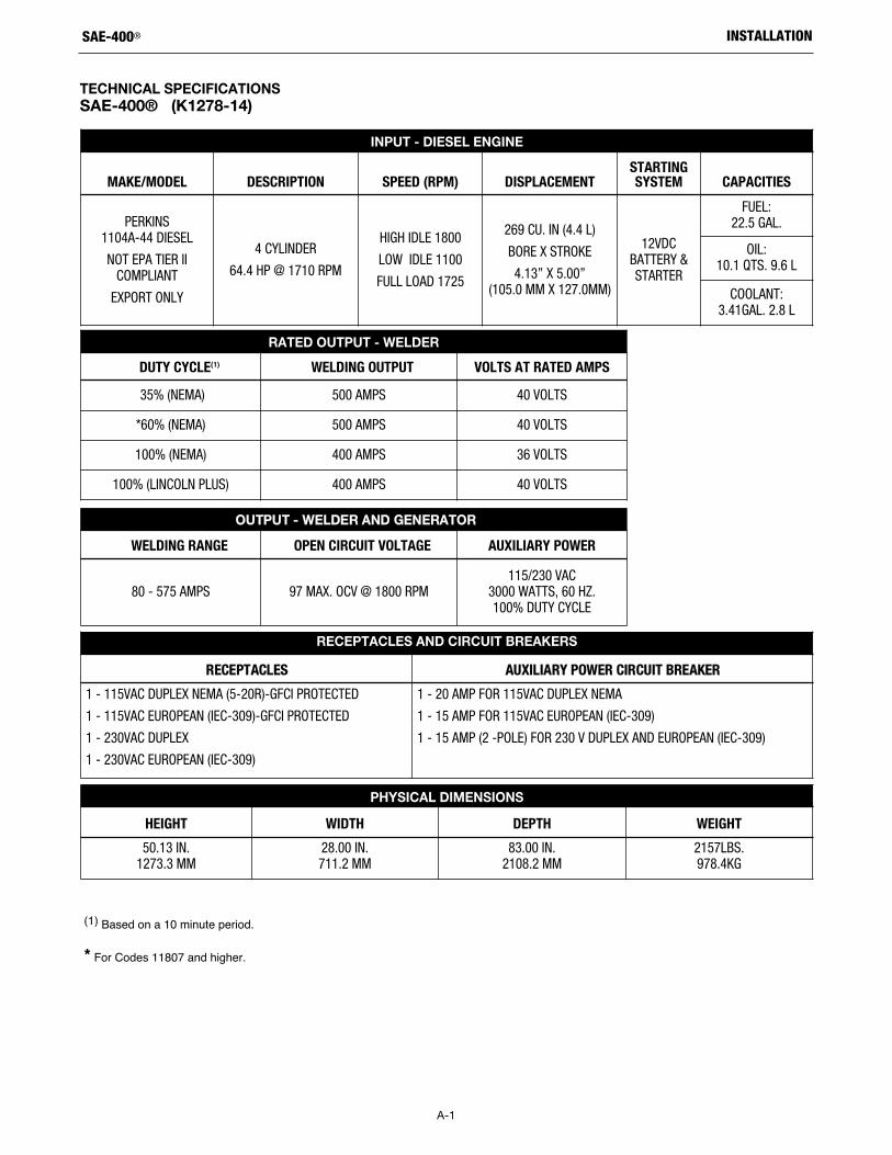
TECHNICAL SPECIFICATIONS
SAE-400® (K1278-14)
(1) Based on a 10 minute period.
* For Codes 11807 and higher.
INPUT - DIESEL ENGINE
MAKE/MODEL DESCRIPTION SPEED (RPM) DISPLACEMENTSTARTINGSYSTEM CAPACITIES
PERKINS1104A-44 DIESEL
NOT EPA TIER IICOMPLIANT
EXPORT ONLY
4 CYLINDER
64.4 HP @ 1710 RPM
HIGH IDLE 1800
LOW IDLE 1100
FULL LOAD 1725
269 CU. IN (4.4 L)
BORE X STROKE
4.13” X 5.00” (105.0 MM X 127.0MM)
12VDCBATTERY &STARTER
FUEL: 22.5 GAL.
OIL: 10.1 QTS. 9.6 L
COOLANT:3.41GAL. 2.8 L
RATED OUTPUT - WELDER
DUTY CYCLE(1) WELDING OUTPUT VOLTS AT RATED AMPS35% (NEMA) 500 AMPS 40 VOLTS
*60% (NEMA) 500 AMPS 40 VOLTS
100% (NEMA) 400 AMPS 36 VOLTS
100% (LINCOLN PLUS) 400 AMPS 40 VOLTS
OUTPUT - WELDER AND GENERATOR
WELDING RANGE OPEN CIRCUIT VOLTAGE AUXILIARY POWER
80 - 575 AMPS 97 MAX. OCV @ 1800 RPM115/230 VAC
3000 WATTS, 60 HZ.100% DUTY CYCLE
RECEPTACLES AND CIRCUIT BREAKERS
RECEPTACLES AUXILIARY POWER CIRCUIT BREAKER1 - 115VAC DUPLEX NEMA (5-20R)-GFCI PROTECTED
1 - 115VAC EUROPEAN (IEC-309)-GFCI PROTECTED
1 - 230VAC DUPLEX
1 - 230VAC EUROPEAN (IEC-309)
1 - 20 AMP FOR 115VAC DUPLEX NEMA
1 - 15 AMP FOR 115VAC EUROPEAN (IEC-309)
1 - 15 AMP (2 -POLE) FOR 230 V DUPLEX AND EUROPEAN (IEC-309)
PHYSICAL DIMENSIONS
HEIGHT WIDTH DEPTH WEIGHT50.13 IN.
1273.3 MM28.00 IN.711.2 MM
83.00 IN.2108.2 MM
2157LBS.978.4KG
A-2
INSTALLATIONSAE-400®
SAFETY PRECAUTIONSRead this entire installation section before you start installation.Do not attempt to use this equipment until you have thoroughlyread all operating and maintenance manuals supplied with yourmachine. They include important safety precautions, detailedengine starting, operating and maintenance instructions and partslists.
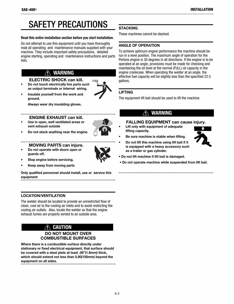
ELECTRIC SHOCK can kill.• Do not touch electrically live parts such
as output terminals or internal wiring.
• Insulate yourself from the work andground.
Always wear dry insulating gloves.
ENGINE EXHAUST can kill.• Use in open, well ventilated areas or
vent exhaust outside
• Do not stack anything near the engine.
MOVING PARTS can injure.• Do not operate with doors open or
guards off.
• Stop engine before servicing.
• Keep away from moving parts
Only qualified personnel should install, use or service thisequipment
LOCATION/VENTILATION
The welder should be located to provide an unrestricted flow ofclean, cool air to the cooling air inlets and to avoid restricting thecooling air outlets. Also, locate the welder so that the engineexhaust fumes are properly vented to an outside area.
DO NOT MOUNT OVER COMBUSTIBLE SURFACES
Where there is a combustible surface directly understationary or fixed electrical equipment, that surface shouldbe covered with a steel plate at least .06”(1.6mm) thick,which should extend not less than 5.90(150mm) beyond theequipment on all sides.
STACKING
These machines cannot be stacked.
ANGLE OF OPERATION
To achieve optimum engine performance the machine should berun in a level position. The maximum angle of operation for thePerkins engine is 30 degrees in all directions. If the engine is to beoperated at an angle, provisions must be made for checking andmaintaining the oil level at the normal (FULL) oil capacity in theengine crankcase. When operating the welder at an angle, theeffective fuel capacity will be slightly less than the specified 22.5gallons.
LIFTING
The equipment lift bail should be used to lift the machine.
FALLING EQUIPMENT can cause injury.• Lift only with equipment of adequate
lifting capacity.
• Be sure machine is stable when lifting.
• Do not lift this machine using lift bail if itis equipped with a heavy accessory suchas a trailer or gas cylinder.
• Do not lift machine if lift bail is damaged.
• Do not operate machine while suspended from lift bail.
WARNING
WARNING
CAUTION
A-3
INSTALLATIONSAE-400®
HIGH ALTITUDE OPERATION
At higher altitudes, output derating may be necessary. As a ruleof thumb, derate the welder output 5% for every 500 meters(1640 ft.) above 1000 meters (3280 ft.).
Contact a Perkins Service Representative for any engineadjustments that may be required for high altitude operation.
TOWING
The recommended trailers for use with this equipment for in-plantand yard towing by a vehicle(1) are Lincoln Electric K2641-2 and K2637-2. The K2637-2 is also designed to be used at highwayspeeds(1).If the user adapts a non-Lincoln trailer, he must assumeresponsibility that the method of attachment and usage does notresult in a safety hazard nor damage the welding equipment.Some of the factors to be considered are as follows:
1. Design capacity of trailer vs. weight of Lincoln Electricequipment and likely additional attachments.
2. Proper support of, and attachment to, the base of the weldingequipment so that there will be no undue stress to thetrailer’s framework.
3. Proper placement of the equipment on the trailer to insurestability side to side and front to back when being moved andwhen standing by itself.
4. Typical conditions of use, such as travel speed, roughness ofsurface on which the trailer will be operated, andenvironmental conditions.
5. Proper preventative maintenance of trailer.
6. Conformance with federal, state and local laws.(1)(1) For highway use, consult applicable federal, state and local laws regarding
specific requirements for use on public highways, such as brakes, lights,fenders, etc.
VEHICLE MOUNTING
Improperly mounted concentrated loads may cause unstable vehicle handling and
tires or other components to fail.
• Only transport this equipment on serviceable vehicleswhich are rated and designed for such loads.
• Distribute, balance and secure loads so vehicle isstable under conditions of use.
• Do not exceed maximum rated loads for componentssuch as suspension, axles and tires.
• Mount equipment base to metal bed or frame of vehicle.
• Follow vehicle manufacturer’s instruction.
PRE-OPERATION ENGINE SERVICE
READ the engine operating and maintenance instructions suppliedwith this machine.
ENGINE OILThe engine is shipped with the engine crankcase filled with highquality SAE 10W-30 oil (API class CD or better). Check the oillevel before starting the engine. If it is not up to the full mark onthe dip stick, add oil as required. Check the oil level every fourhours of running time during the first 35 running hours. Refer tothe engine Operator’s Manual for specific oil recommendationsand break-in information. The oil change interval is dependent onthe quality of the oil and the operating environment. Refer to theengine Operator’s Manual for the proper service and maintenanceintervals.
WARNING
A-4
INSTALLATIONSAE-400®
DIESEL FUEL can cause fire.• Stop engine while fueling.
• Do not smoke when fueling.
• Keep sparks and flame away from tank.
• Do not leave unattended while fueling.
• Wipe up spilled fuel and allow fumes to clear beforestarting engine.
• Do not overfill tank, fuel expansion may cause overflow.
DIESEL FUEL ONLY
Fill the fuel tank with clean, fresh diesel fuel. The capacity of thefuel tank is 22.5 gallons (85.1 liters). See engine Operator’sManual for specific fuel recommendations.
Note: Before starting the engine, be sure the fuel shutoff valve isin the open position.
ENGINE COOLING SYSTEM
The cooling system has been filled at the factory with a 50-50mixture of ethylene glycol antifreeze and water. Check theradiator level and add a 50-50 solution as needed. (See EngineManual or antifreeze container for alternate antifreeze recom-mendation.)
ENGINE BREAK-IN PERIOD
Lincoln Electric selects high quality, heavy-duty industrial enginesfor the portable welding machines we offer. While it is normal tosee a small amount of crankcase oil consumption during initialoperation, excessive oil use, wet stacking (oil or tar like substanceat the exhaust port), or excessive smoke is not normal.
Larger machines with a capacity of 350 amperes and higher,which are operated at low or no-load conditions for extendedperiods of time are especially susceptible to the conditionsdescribed above. To accomplish successful engine break-in, mostdiesel-powered equipment needs only to be run at a reasonablyheavy load within the rating of the welder for some period of timeduring the engine’s early life. However, if the welder is subjectedto extensive light loading, occasional moderate to heavy loading ofthe engine may sometimes be necessary. Caution must beobserved in correctly loading a diesel/generator unit.
1. Connect the welder output studs to a suitable resistive loadbank. Note that any attempt to short the output studs byconnecting the welding leads together, direct shorting of theoutput studs, or connecting the output leads to a length ofsteel will result in catastrophic damage to the generator andvoids the warranty.
2. Set the welder controls for an output current and voltagewithin the welder rating and duty cycle. Note that anyattempt to exceed the welder rating or duty cycle for anyperiod of time will result in catastrophic damage to thegenerator and voids the warranty.
3. Periodically shut off the engine and check the crankcase oillevel.
BATTERY CONNECTION
• Use caution as the electrolyte is a strong acid that canburn skin and damage eyes.
• Remove and discard the insulating cap from thenegative battery terminal. Attach and tighten negativebattery cable terminal.
NOTE: This machine is furnished with a wet charged battery; ifunused for several months, the battery may require a boostercharge. Be careful to charge the battery with the correct polarity.Make sure that the battery is level while charging.
Gases from battery can explode.
Keep sparks, flame and cigarettes awayfrom battery.
To prevent EXPLOSION when:
• INSTALLING A NEW BATTERY — disconnect negativecable from old battery first and connect to new batterylast.
• CONNECTING A BATTERY CHARGER — removebattery from welder by disconnecting negative cablefirst, then positive cable and battery clamp. Whenreinstalling, connect negative cable last. Keep wellventilated.
• USING A BOOSTER — connect positive lead to batteryfirst then connect negative lead to negative battery leadat the lower control panel support.
BATTERY ACID can burn eyes and skin.
• Wear gloves and eye protection and becareful when working near battery.
• Follow instructions printed on battery.
IMPORTANT: To prevent ELECTRICAL DAMAGE WHEN:
a) Installing a new batterie.
b) Using a booster.
Use correct polarity — Negative Ground.
To prevent BATTERY BUCKLING, tighten the nuts on batteryuntil snug. DO NOT OVERTIGHTEN.
WARNING
WARNING
WARNING
A-5
INSTALLATIONSAE-400®
SPARK ARRESTER
• Spark Arrester and Muffler may be hot!
• Allow engine to cool before servicingspark arrester!
• Do not operate engine while servicingspark arrester!
Some federal, state or local laws may require that gasoline ordiesel engines be equipped with exhaust spark arresters whenthey are operated in certain locations where unarrested sparksmay present a fire hazard. The muffler included with this welderhas been modified and now qualifies as a spark arrester. Sparkarresting mufflers will have a clean out service plug and will have“USDA FS 5100-1c QUALIFIED SPARK ARRESTER” or “US FORESTSERVICE APPROVED” stamped on the muffler shell. Any sparkarrester must be serviced and properly maintained.
An incorrect arrester may lead to damage tothe engine or adversely affect performance.
WELDING OUTPUT CABLES
With the engine off, connect the electrode and work cables to thestuds provided. These connections should be checked periodicallyand tightened if necessary.
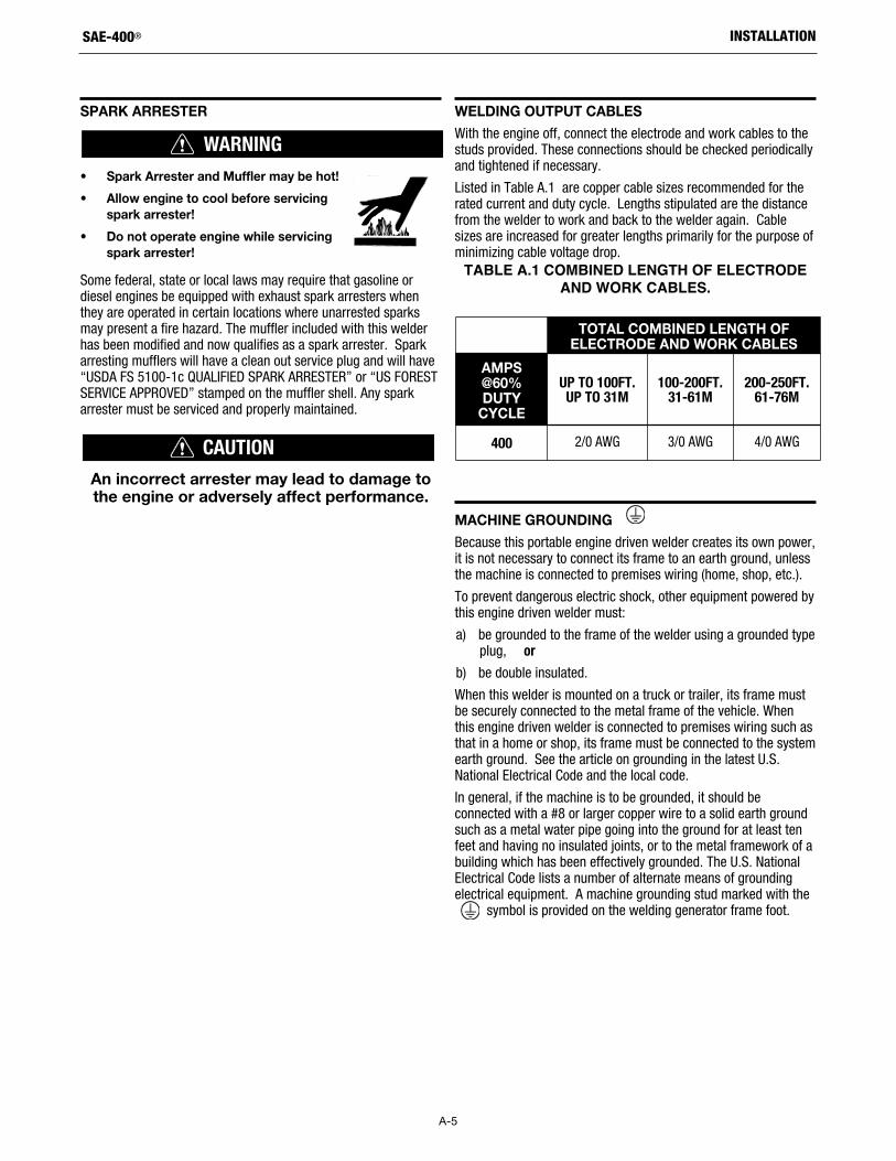
Listed in Table A.1 are copper cable sizes recommended for therated current and duty cycle. Lengths stipulated are the distancefrom the welder to work and back to the welder again. Cablesizes are increased for greater lengths primarily for the purpose ofminimizing cable voltage drop.
TABLE A.1 COMBINED LENGTH OF ELECTRODEAND WORK CABLES.
MACHINE GROUNDING
Because this portable engine driven welder creates its own power,it is not necessary to connect its frame to an earth ground, unlessthe machine is connected to premises wiring (home, shop, etc.).
To prevent dangerous electric shock, other equipment powered bythis engine driven welder must:
a) be grounded to the frame of the welder using a grounded typeplug, or
b) be double insulated.
When this welder is mounted on a truck or trailer, its frame mustbe securely connected to the metal frame of the vehicle. Whenthis engine driven welder is connected to premises wiring such asthat in a home or shop, its frame must be connected to the systemearth ground. See the article on grounding in the latest U.S.National Electrical Code and the local code.
In general, if the machine is to be grounded, it should beconnected with a #8 or larger copper wire to a solid earth groundsuch as a metal water pipe going into the ground for at least tenfeet and having no insulated joints, or to the metal framework of abuilding which has been effectively grounded. The U.S. NationalElectrical Code lists a number of alternate means of groundingelectrical equipment. A machine grounding stud marked with the
symbol is provided on the welding generator frame foot.
WARNING
CAUTION
TOTAL COMBINED LENGTH OF ELECTRODE AND WORK CABLES
AMPS@60%DUTY
CYCLE
UP TO 100FT.UP TO 31M
100-200FT.31-61M
200-250FT.61-76M
400 2/0 AWG 3/0 AWG 4/0 AWG
B-1
OPERATION
OPERATIONRead this entire installation section before you start installation.
SAFETY INSTRUCTIONS
Do not attempt to use this equipment until you havethoroughly read all operating and maintenance manualssupplied with your machine. They include important safetyprecautions, detailed engine starting, operating andmaintenance instructions and parts lists.
ELECTRIC SHOCK can kill.• Do not touch electrically live parts or
electrodes with your skin or wet clothing.
• Insulate yourself from the work andground.
• Always wear dry insulating gloves.
• Do not use AC welder if your clothing, gloves or workarea is damp or if working on, under or insideworkpiece.
Use the following equipment:
• Semiautomatic DC constant voltage (wire) welder.
• DC manual (stick) welder.
• AC welder with reduced voltage control.
ARC RAYS can injure eyes andburn skin.
Wear eye, ear, and body protection.
• Only qualified personnel should install, use orservice this equipment.
• Consult instruction manual before operating.
Before operating, read and understand the manufacturersinstructions for this equipment and the consumables to beused including the Material Safety Data Sheet (MSDS) andfollow your employer’s safety practices.
FUMES AND GASES can be dangerous to your health.
• Keep your head out of fumes.
• Use enough ventilation or exhaust at thearc, or both, to keep the fumes and gasesfrom your breathing zone and general area.
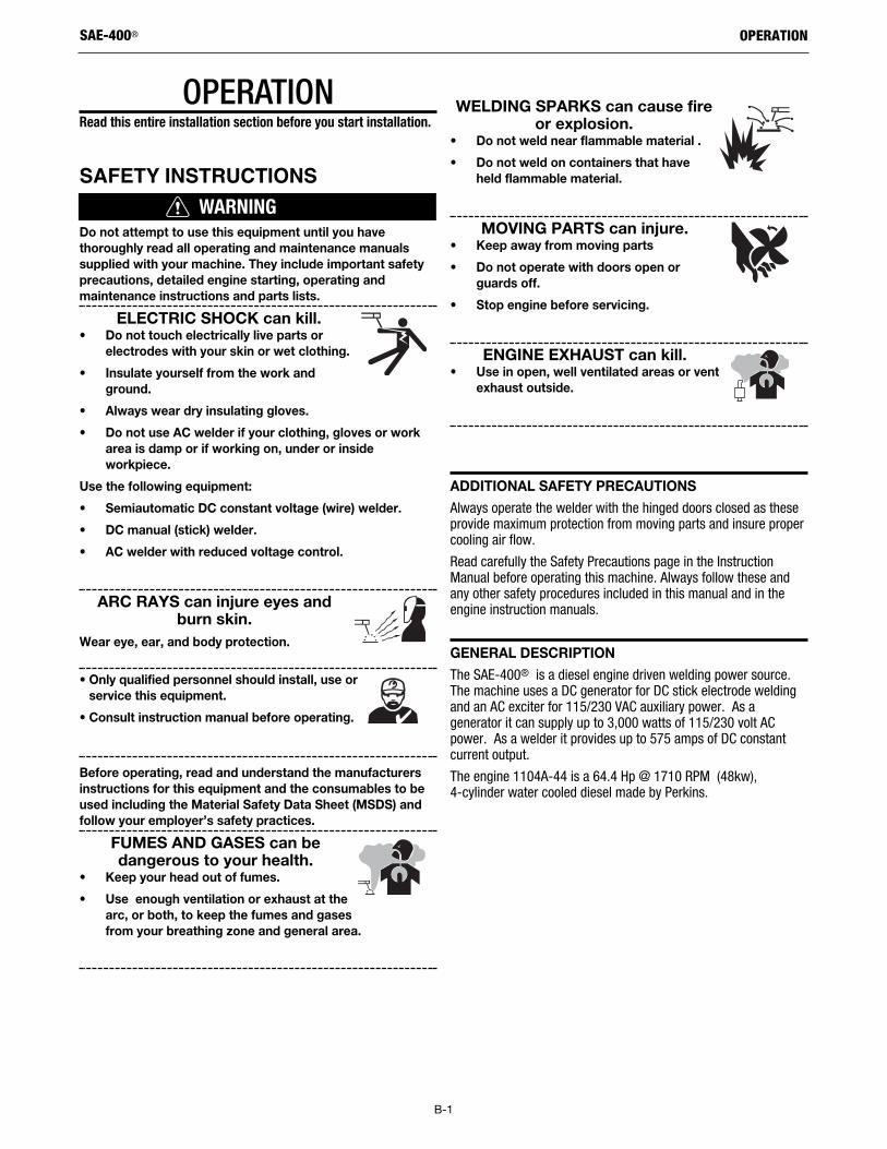
WELDING SPARKS can cause fireor explosion.
• Do not weld near flammable material .
• Do not weld on containers that haveheld flammable material.
MOVING PARTS can injure.• Keep away from moving parts
• Do not operate with doors open orguards off.
• Stop engine before servicing.
ENGINE EXHAUST can kill.• Use in open, well ventilated areas or vent
exhaust outside.
ADDITIONAL SAFETY PRECAUTIONS
Always operate the welder with the hinged doors closed as theseprovide maximum protection from moving parts and insure propercooling air flow.
Read carefully the Safety Precautions page in the InstructionManual before operating this machine. Always follow these andany other safety procedures included in this manual and in theengine instruction manuals.
GENERAL DESCRIPTION
The SAE-400® is a diesel engine driven welding power source.The machine uses a DC generator for DC stick electrode weldingand an AC exciter for 115/230 VAC auxiliary power. As agenerator it can supply up to 3,000 watts of 115/230 volt ACpower. As a welder it provides up to 575 amps of DC constantcurrent output.
The engine 1104A-44 is a 64.4 Hp @ 1710 RPM (48kw), 4-cylinder water cooled diesel made by Perkins.
SAE-400®
WARNING
B-2
OPERATION
RECOMMENDED APPLICATIONS
WELDERThe SAE-400® provides excellent constant current DC weldingoutput for stick (SMAW) welding. The field installed optional CVAdapter (K385-[ ]) provides up to 500 amps at 35 volts of constantvoltage output for semiautomatic welding.
AUXILIARY POWERThe SAE-400® provides 3 KW of 115/230 VAC output forauxiliary power and emergency standby power.
DESIGN FEATURES AND ADVANTAGES
FOR STICK WELDING• Excellent DC constant current output for stick welding appli-
cations.
• Continuous adjustment of both voltage and current forunsurpassed welds on demanding jobs.
• Remote control capability standard.
FOR AUXILIARY POWER• 3,000 watts of 115/230VAC, 60 Hz auxiliary power.
• One 20 amp 115VAC duplex receptacle.
• One 15 amp, 230VAC duplex receptacle for up to 13 amps of230VAC power.
• One 115VAC (European IEC-309) 16 amp receptacle.
• One 230VAC (European IEC-309) 15 amp receptacle.
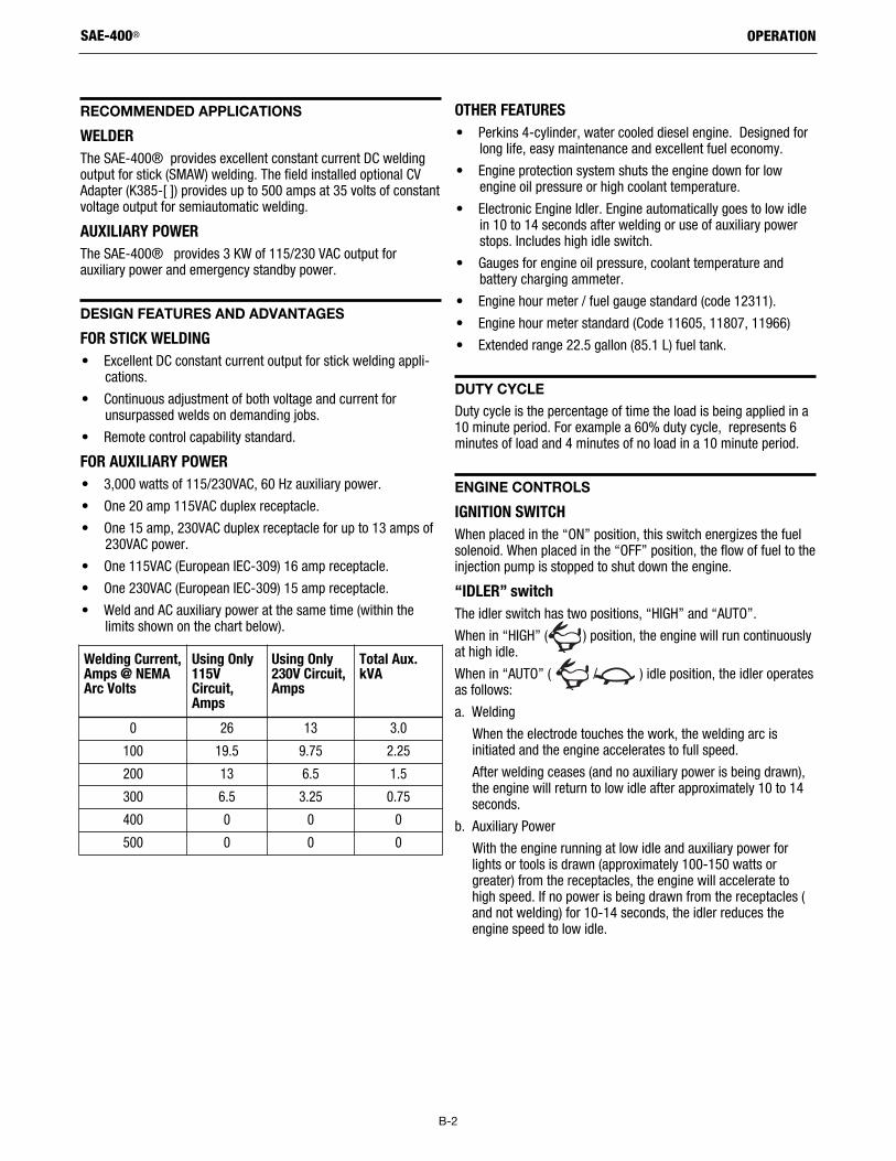
• Weld and AC auxiliary power at the same time (within thelimits shown on the chart below).
OTHER FEATURES• Perkins 4-cylinder, water cooled diesel engine. Designed for
long life, easy maintenance and excellent fuel economy.
• Engine protection system shuts the engine down for lowengine oil pressure or high coolant temperature.
• Electronic Engine Idler. Engine automatically goes to low idlein 10 to 14 seconds after welding or use of auxiliary powerstops. Includes high idle switch.
• Gauges for engine oil pressure, coolant temperature andbattery charging ammeter.
• Engine hour meter / fuel gauge standard (code 12311).
• Engine hour meter standard (Code 11605, 11807, 11966)
• Extended range 22.5 gallon (85.1 L) fuel tank.
DUTY CYCLE
Duty cycle is the percentage of time the load is being applied in a10 minute period. For example a 60% duty cycle, represents 6minutes of load and 4 minutes of no load in a 10 minute period.
ENGINE CONTROLS
IGNITION SWITCHWhen placed in the “ON” position, this switch energizes the fuelsolenoid. When placed in the “OFF” position, the flow of fuel to theinjection pump is stopped to shut down the engine.
“IDLER” switchThe idler switch has two positions, “HIGH” and “AUTO”.
When in “HIGH” ( ) position, the engine will run continuouslyat high idle.
When in “AUTO” ( / ) idle position, the idler operatesas follows:
a. Welding
When the electrode touches the work, the welding arc isinitiated and the engine accelerates to full speed.
After welding ceases (and no auxiliary power is being drawn),the engine will return to low idle after approximately 10 to 14seconds.
b. Auxiliary Power
With the engine running at low idle and auxiliary power forlights or tools is drawn (approximately 100-150 watts orgreater) from the receptacles, the engine will accelerate tohigh speed. If no power is being drawn from the receptacles (and not welding) for 10-14 seconds, the idler reduces theengine speed to low idle.
SAE-400®
Welding Current,Amps @ NEMAArc Volts
Using Only115VCircuit,Amps
Using Only230V Circuit,Amps
Total Aux.kVA
0 26 13 3.0
100 19.5 9.75 2.25
200 13 6.5 1.5
300 6.5 3.25 0.75
400 0 0 0
500 0 0 0
B-3
OPERATION
ENGINE TEMPERATURE GAUGEDisplays the coolant temperature in the engine block.
ENGINE Oil Pressure GaugeDisplays the oil pressure to the engine. When the engine startsrunning, watch for the oil pressure to build up. If no pressureshows within 30 seconds, stop the engine and consult the engineinstruction manual.
Battery Charging AmmeterDisplays the current going from the charging alternator into thebatteries. It is normal for charging current to be high (above 15amps) after starting or when the batteries are ‘low’ on charge.
Engine Hour MeterThe engine hour meter records the total running time on theengine in hours. It can be used to keep a record of maintenanceon the engine and or welder.
For code 12311, the engine hour meter & engine fault indicatorLED are built-in the fuel guage.
Engine Protection SystemThe engine protection system shuts down the engine under highcoolant temperature or low engine oil pressure conditions byallowing the fuel solenoid valve to close.
WELDER CONTROLS
POLARITY SWITCHTurn the Arc Polarity switch to electrode positive or electrodenegative as required for each particular application.
CONTROL OF WELDING CURRENTPurpose of ControlsThe continuous “Current Control” is the main current adjuster. The“Job Selector” is both a fine current adjuster and the continuousOpen Circuit Voltage adjuster. Open Circuit Voltage (OCV) controlsthe arc characteristics.
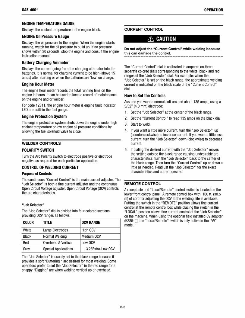
“Job Selector”The “Job Selector” dial is divided into four colored sectionsproviding OCV ranges as follows:
The “Job Selector” is usually set in the black range because itprovides a soft “Buttering “ arc desired for most welding. Someoperators prefer to set the “Job Selector” in the red range for asnappy “Digging” arc when welding vertical up or overhead.
CURRENT CONTROL
Do not adjust the “Current Control” while welding becausethis can damage the control.
The “Current Control” dial is calibrated in amperes on threeseparate colored dials corresponding to the white, black and redranges of the “Job Selector” dial. For example: when the “Job Selector” is set on the black range, the approximate weldingcurrent is indicated on the black scale of the “Current Control”dial.
How to Set the ControlsAssume you want a normal soft arc and about 135 amps, using a5/32” (4.0 mm) electrode:
1. Set the “Job Selector” at the center of the black range.
2. Set the “Current Control” to read 135 amps on the black dial.
3. Start to weld.
4. If you want a little more current, turn the “Job Selector” up(counterclockwise) to increase current. If you want a little lesscurrent, turn the “Job Selector” down (clockwise) to decreasecurrent.
5. If dialing the desired current with the “Job Selector” movesthe setting outside the black range causing undesirable arccharacteristics, turn the “Job Selector” back to the center ofthe black range. Then turn the “Current Control” up or down alittle as needed. Readjust the “Job Selector” for the exactcharacteristics and current desired.
REMOTE CONTROL
A receptacle and “Local/Remote” control switch is located on thelower front control panel. A remote control box with 100 ft. (30.5m) of cord for adjusting the OCV at the welding site is available.Putting the switch in the “REMOTE” position allows fine currentcontrol at the remote control box while placing the switch in the“LOCAL” position allows fine current control at the “Job Selector”on the machine. When using the optional field installed CV adapter(K385-[ ]) the “Local/Remote” switch is only active in the “VV”mode.
SAE-400®
COLOR TITLE OCV RANGEWhite Large Electrodes High OCV
Black Normal Welding Medium OCV
Red Overhead & Vertical Low OCV
Grey Special Applications 3.25Extra-Low OCV
CAUTION
B-4
OPERATION
AUxILIARY POWER CONTROLS
115 VAC ReceptacleOne 20 amp, 115VAC (5-20R) NEMA duplex receptacle provides115VAC for auxiliary power. Maximum current is 20 amps total.
One 115V (European IEC-309) 16 amp receptacle. IP44 rated.
230VAC ReceptacleOne 15 amp, 230VAC duplex receptacle provides 230 VAC forauxiliary power. A total of 13 amps can be drawn from thisreceptacle.
One 230V (European IEC-309) 15 amp receptacle. IP44 rated.
Circuit Breakers2 pole 15 amp rated provides overload protection for the 230VAC(European IEC-309) receptacle and the 230VAC duplex receptacle.
Single pole 15 amp rated provides overload protection for the115VAC (European IEC-309) receptacle.
Single pole 15 amp rated provides overload protection for the115VAC (5-20R) NEMA duplex receptacle.
GFCI (Ground Fault Circuit Interrupter):• Protects both 115VAC auxiliary power receptacles.
• If the GFCI is tripped, see the Maintenence Section fordetailed information on testing and resetting the GFCI.
The GFCI (Ground Fault Circuit Interrupter) electrical receptacle isa device to protect against electric shock should a piece ofdefective equipment connected to it develop a ground fault. If thissituation should occur, the GFCI will trip, removing voltage fromthe output of the receptacle. If the GFCI is tripped see theMAINTENANCE section for detailed information on testing andresetting it. The GFCI should be properly tested at least once everymonth.
The 115V auxiliary power receptacles should only be used withthree wire grounded type plugs or approved double insulated toolswith two wire plugs. The current rating of any plug used with thesystem must be at least equal to the current capacity of theassociated receptacle.
RESIDUAL CURRENT DEVICEThe SAE-400® is configured to allow for the addition of aResidual Current Device (RCD) to protect the 240V Single PhaseReceptacle. The lower Control Panel has a rectangular cut-out toaccept a typical 2-pole RCD along with a protective rubber boot. Acover plate a label “RCD READY” covers the rectangular cut-out,and secures a mounting bracket on the backside of the panel.
Note: The (RCD) should be rated for at least 15 amps.
There are many suppliers of RCD’s. One example is Clipsal, partnumber 4RC225/30.
The protective boot can be obtained from:
APM-Hexseal, part number HE-1035.
See Section F Diagrams of this Operator’s Manual for instructionson installing an RCD and protective rubber boot.
Ground StudProvides a connection point for connecting the machine to earthground. For the safest grounding procedure refer to “MachineGrounding” in the INSTALLATION section of this manual.
SAE-400®
B-5
OPERATION
ENGINE OPERATION
Do not attempt to use this equipment until you havethoroughly read the engine manufacturer’s manual suppliedwith your welder. It includes important safety precautions,detailed engine starting, operating and maintenanceinstructions, and parts lists.
ELECTRIC SHOCK can kill.• Do not touch electrically live parts or
electrode with skin or wet clothing.
• Insulate yourself from work and ground
• Always wear dry insulating gloves.
ENGINE EXHAUST can kill.• Use in open, well ventilated areas or
vent exhaust outside.
MOVING PARTS can injure.• Do not operate with doors open or
guards off.
• Stop engine before servicing.
• Keep away from moving parts.
See additional warning information at the front of this operator’smanual.For added safety always operate the welder with the doors closed.Further, leaving the doors open changes the designed air flow andmay cause engine, generator overheating.
Do not adjust the high idle engine speed (rpm) above thefactory setting specification as this will void warranty.
STARTING INSTRUCTIONS
Be sure all Pre-Operation Maintenance has been performed. (SeeINSTALLATION section of this manual).
1. Turn the “IDLER” switch to “HIGH”.
2. Turn the “IGNITION” switch to “ON”.
3. Press the Glow Plug button for 20 to 30 seconds. (maximum60 seconds).
4. Press the Glow Plug and the Start button at the same time.When the engine starts running, release both buttons. If theengine fails to start in 20 seconds, wait 30 seconds andrepeat the above procedure.
5. Observe the oil pressure. If no pressure shows within 30seconds, stop the engine and consult the engine operatingmanual. To stop the engine, turn the “IGNITION” switch to“OFF”.
6. If the engine protection warning light comes on duringcranking or after start up, the “IGNITION” switch must beturned “OFF” to reset the engine protection system.
7. Allow the engine to run at high idle speed for several minutesto warm the engine. Stop the engine and recheck the oil level,after allowing sufficient time for the oil to drain into the pan. Ifthe level is down, fill it to the full mark again. The enginecontrols were properly set at the factory and should require noadjusting when received.
COLD WEATHER STARTING:Under NO conditions should ether or other starting fluids beused!
With a fully charged battery and the proper weight oil, the engineshould start satisfactorily even down to about -5°F (-20°C), itmaybe desirable to install cold-starting aides.
Note: Extreme cold weather staring may require longer glow plugoperation.
STOPPING THE ENGINE
1. Turn the “IGNITION” switch to “OFF”
At the end of each day’s welding, check the crankcase oil level,drain accumulated dirt and water from the water separator andrefill the fuel tank to minimize moisture condensation in the tank.Also, running out of fuel tends to draw dirt into the fuel system.
When hauling the welder between job sites, close the fuel shut-offvalve.
If the fuel supply is cut off or runs out while the fuel pump isoperating, air may be entrapped in the fuel distribution system. Ifthis happens, bleeding of the fuel system may be necessary. Usequalified personnel to do this per the instructions in theMAINTENANCE section of this manual.
SAE-400®
WARNING
CAUTION
WARNING
B-6
OPERATION
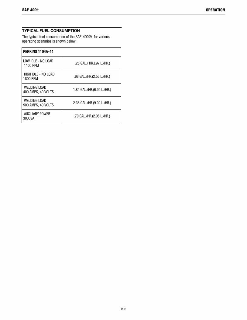
TYPICAL FUEL CONSUMPTION
The typical fuel consumption of the SAE-400® for variousoperating scenarios is shown below:
SAE-400®
PERKINS 1104A-44
LOW IDLE - NO LOAD1100 RPM .26 GAL./ HR.(.97 L./HR.)
HIGH IDLE - NO LOAD1800 RPM .68 GAL./HR.(2.56 L./HR.)
WELDING LOAD 400 AMPS, 40 VOLTS 1.84 GAL./HR.(6.95 L./HR.)
WELDING LOAD 500 AMPS, 40 VOLTS 2.38 GAL./HR.(9.02 L./HR.)
AUXILIARY POWER3000VA .79 GAL./HR.(2.98 L./HR.)
C-1
ACCESSORIES
ACCESSORIESK930-2 TIG Module - Provides high frequency plus a gas valve forTIG welding. A water valve is available as an option. Requires 115volt AC input. (Limited to 250A - 60% Duty Cycle).
K802-D Power Plug Kit - Kit includes male plug for 20 ampreceptacle.
K2641-2 Trailer - FOUR-WHEEL STEERABLE YARD TRAILER WITHDUO-HITCH
• For off-road, plant and yard use with an overall width of 55 in.
• Includes an automatically engaging drawbar lock when thedrawbar is raised to the vertical position.
• 13 in wheels with wheel bearings packed with high viscosity,high pressure, low washout Lubriplate® grease.
• Stiff 3/16 in welded rectangular steel frame construction isphosphate etched and powder coat painted for superior rustand corrosion resistance.
• Also includes a Duo-Hitch™ - a 2 in Ball/Lunette Eyecombination hitch.
K2637-2 Trailer - A 2-wheel trailer designed for road(1), off road,in-plant and yard towing. Trailer mounts directly to welder base.Comes standard with a Duo-Hitch™, a 2” Ball and Lunette Eyecombination hitch.
Order:
K2636-1 Trailer
K2639-1 Fender & Light Kit
K2640-1 Cable Storage Rack1For highway use, consult applicable federal, state and local laws regarding
possible requirements for brakes, lights, fenders, etc.
Pipe Thawing with an arc welder can cause fire, explosion,damage to electric wiring or to the arc welder if doneimproperly. The use of an arc welder for pipe thawing is notapproved by the CSA, nor is it recommended or supportedby Lincoln Electric.
K704 Standard Accessory Kit - Includes electrode and workcables, headshield, work clamp and electrode holder.
K385-[ ] CV Adapter - Provides constant voltage output forsemiautomatic welding. (Field installation only).
K1735-1 MULTI-WELD 350 - For multiple arcs from the DC outputof a welding power source. See bulletin E5.300 for Multi-Weld 350and distribution system.
K2144-1 Oil Drain Kit- Includes ball valve, hose and clamp.
SAE-400®
WARNING
D-1
MAINTENANCE
MAINTENANCE
ELECTRIC SHOCK can kill.• Do not touch electrically live parts
such as output terminals or internalwiring
ENGINE EXHAUST can kill.• Use in open, well ventilated areas or
vent exhaust outside
MOVING PARTS can injure.• Do not operate with doors open or
guards off
• Stop engine before servicing
• Keep away from moving parts
• Remove guards only when necessary and replace whenwork requiring removal is complete.
• Only qualified personnel should install, use, or servicethis equipment.
ROUTINE MAINTENANCE
At the end of each day’s welding, refill the fuel tank to minimizemoisture condensation in the tank. Also, running out of fuel tendsto draw dirt into the fuel system. Check the engine crankcase oillevels.
If the fuel supply runs out while the fuel pump is operating, airmay be entrapped in the fuel distribution system. If this happens,bleeding of the fuel system may be necessary. See the engineinstruction manual.
ENGINE AIR FILTER
The engine air filter element is a dry cartridge type. It is locatedabove the engine. It can be cleaned and re-used; however,damaged elements should not be washed or re-used. Removeloose dirt from element with compressed air or water hosedirected from inside out. Compressed Air: 100 psi maximum. Thefilter should never be removed while the engine is running.
PERIODIC MAINTENANCE
1. Blow out the welder and controls with an air hose at leastonce every two months. In particularly dirty locations, thiscleaning may be necessary once a week. Use low pressureair to avoid driving dirt into the insulation.
2. The current control reactor brushes are self-lubricating andshould not be greased. Keep the contacts clean. This controlshould be moved from maximum to minimum daily to preventthe controls from sticking.
3. See the engine Instruction Manual for periodic enginemaintenance information. Change the crankcase oil at regularintervals using the proper grade of oil as recommended in theengine operating manual. Change the oil filter in accordancewith the instructions in the engine operating manual. Whenthe oil filter is changed add one quart of oil to the crankcaseto replace the oil held in the filter during operation.
4. Belts tend to loosen after the first 30 or 40 hours of operation.Check the cooling fan belt and tighten if necessary. DO NOTOVER TIGHTEN.
Bearing Maintenance(For Code 11605 only)
This welder is equipped with a double-shielded ball bearinghaving sufficient grease to last indefinitely under normal service.Where the welder is used constantly or in excessively dirtylocations, it may be necessary to add one-half ounce of grease peryear. A pad of grease one inch wide, one inch long and one inchhigh weighs approximately one-half ounce. Over greasing is farworse than insufficient greasing.
When greasing the bearings, keep all dirt out of the area. Wipe thefittings completely clean and use clean equipment. More bearingfailures are caused by dirt introduced during greasing than frominsufficient grease.
SAE-400®
WARNING
D-2
MAINTENANCE
Commutator and Brush Maintenance
Uncovered rotating equipment can be dangerous. Use careso your hands, hair, clothing or tools do not catch in therotating parts. Protect yourself from particles that may bethrown out by the rotating armature when stoning thecommutator.
The generator brushes are properly adjusted when the welder isshipped. They require no particular attention. DO NOT SHIFT THEBRUSHES or adjust the rocker setting.
Shifting of the brushes may result in:
- Change in machine output
- Commutator Damage
- Excessive brush wear
Periodically inspect the commutator, slip rings and brushes byremoving the covers. DO NOT remove or replace these coverswhile the machine is running.
Commutators and slip rings require little attention. However, ifthey are black or appear uneven, have them cleaned by anexperienced maintenance person using fine sandpaper or acommutator stone. Never use emery cloth or paper for thispurpose.
NOTE: If the welder is used in dirty or dusty locations, or if thewelder is not used for prolonged periods of time, it may benecessary to clean the commutator and slip rings more often.
Replace brushes when they wear within 1/4" of the pigtail. Acomplete set of replacement brushes should be kept on hand.Lincoln brushes have a curved face to fit the commutator. Have anexperienced maintenance person seat these brushes by lightlystoning the commutator as the armature rotates at full speed untilcontact is made across the full face of the brushes. After stoning,blow out the dust with low pressure air.
To seat the slip ring brushes, position the brushes in place. Thenslide one end of a piece of fine sandpaper between slip rings andbrushes with the coarse side against the brushes. With slightadditional finger pressure on top of the brushes, pull thesandpaper around the circumference of the rings, in direction ofrotation only - until brushes seat properly. In addition, stone slipring with a fine stone. Brushes must be seated 100%.
Arcing or excessive exciter brush wear indicates a possiblemisaligned shaft. Have an authorized Field Service Shop checkand realign the shaft.
Cooling SystemThe SAE-400® is equipped with a pressure radiator. Keep theradiator cap tight to prevent loss of coolant. Clean and flush thecooling system periodically to prevent clogging the passage andoverheating the engine. When antifreeze is needed, always usethe permanent type.
Fuel Pre-Filter/Water Separator Assembly
When working on the fuel system
• Keep unguarded lights away, do notsmoke !
• Do not spill fuel !
The SAE-400® is equipped with a Fuel Pre-Filter/Water SeparatorAssembly located before the lift pump mounted to the engineblock.
The assembly uses a 30 micron pre-filter/water separator elementthat is designed to protect against gross contamination of the finalfuel filter. Using chemically treated paper media the element alsoprovides maximum protection against water in the fuel. Theassembly is also equipped with a see-through bowl for easy visualchecking for water. The recommended change interval for thepre-filter/water separator element is 1,000 hours. See below forinformation on the see-through bowl and for the procedure forchanging the element.
See-Through Bowl:
• Check the see-through bowl for water regularly. Water willcollect at the bottom of the bowl and appears different fromthe fuel.
Note: The see-through bowl is re-usable.
1. Close the fuel shut-off valve.
2. Drain by opening the self venting drain valve and allowing allwater to escape.
3. Close the drain valve and open the fuel shut-off valve.
Pre-Filter/Water Separator Element:
1. Close the fuel shutoff valve located under the fuel tank.
2. Rotate the quick change ring (located just below filterheader)clockwise approximately 1/2 turn and slide it down and off ofthe element.
3. Grasp the element and pull down with a slight rocking motionto remove the element from the grommet post on the bottomof the filter header.
4. Slide the new element onto the grommet post on the bottomof the filter header until the element no longer easily movesup into the filter header. Now rotate the element (may takealmost 1 full turn) with a slight upward pressure until theelement begins to further engage the header. With the properorientation now established apply additional pressure to seatthe element in the filter header. You should feel the element“pop” into place when properly seated.
Note: The element will only go on one way. Never useexcessive force when mounting the element to the header.
SAE-400®
WARNING
WARNING
D-3
MAINTENANCE
5. Slide the quick change ring up over the element and rotatecounter clockwise until an audible click or pop is heard. If youdo not hear the click you have not rotated the ring far enoughand the element is not in the locked position. Anotherindication that the ring is in the locked position is that one set(it doesn’t matter which one) of arrows located on the outsideof the ring should be located directly under the air vent valve.
6. Remove the see-through bowl from the old element andinstall on the new element.
7. Open the fuel shutoff valve.
8. Open the air vent valve on the front of the filter header untilfuel emerges free of air bubbles and then close the air ventvalve.
Note: Consult your engine operation manual for informationon air bleeding the entire fuel system.
Engine and Maintenance components
SPARK ARRESTOR
• Spark Arrester and Muffler may be hot!
• Allow engine to cool before servicingspark arrester!
• Do not operate engine while servicingspark arrester!
SAE-400® with integral spark arresting mufflers:Service spark arrester every 250 hours.
Service as follows:
1. Stop engine and allow to cool.
2. Remove clean out plug from side of spark arrester.
3. Without damaging the spark arrester, gently tap on thearrester shell near the clean out plug.
4. Once particles are removed, replace the clean out plug.
GFCI Testing AND RESETTING ProcedureThe GFCI should be properly tested at least once every month orwhenever it is tripped. To properly test and reset the GFCI:
• If the GFCI has tripped, first carefully remove any load andcheck it for damage.
• If the equipment has been shut down, it must be restarted.
• The equipment needs to be operating at high idle speed andany necessary adjustments made on the control panel so thatthe equipment is providing at least 80 volts to the receptacleinput terminals.
• The circuit breaker for this receptacle must not be tripped.Reset if necessary.
• Push the "Reset" button located on the GFCI. This will assurenormal GFCI operation.
• Plug a night-light (with an "ON/OFF" switch) or other product(such as a lamp) into the Duplex receptacle and turn theproduct "ON".
• Push the "Test" button located on the GFCI. The night-light orother product should go "OFF".
• Push the "Reset" button, again. The light or other productshould go "ON" again.
If the light or other product remains "ON" when the "Test" buttonis pushed, the GFCI is not working properly or has been incorrectlyinstalled (miswired). If your GFCI is not working properly, contact aqualified, certified electrician who can assess the situation, rewirethe GFCI if necessary or replace the device.
SAE-400®
ITEM MAKE PART NUMBER
Engine Air Filter Donaldson P822768
Fan Belt Perkins 2614B555 043
Fuel Filter Perkins 26560201
Engine Oil Filter Perkins 2654407
Pre-Filter/WaterSeparator Element
Lincoln M21584-B
Stanadyne 39420 LE
WARNING
E-1
TROUBLESHOOTINGSAE-400®
If for any reason you do not understand the test procedures or are unable to perform the tests/repairs safely, contact your Local Lincoln AuthorizedField Service Facility for technical troubleshooting assistance before you proceed.
CAUTION
Observe all additional Safety Guidelines detailed throughout this manual.
This Troubleshooting Guide is provided to help you locate and repairpossible machine malfunctions. Simply follow the three-step procedurelisted below.
Step 1. LOCATE PROBLEM (SYMPTOM).Look under the column labeled “PROBLEM (SYMPTOMS).” This columndescribes possible symptoms that the machine may exhibit. Find the listingthat best describes the symptom that the machine is exhibiting.
Step 2. POSSIBLE CAUSE.The second column labeled “POSSIBLE CAUSE” lists the obvious externalpossibilities that may contribute to the machine symptom.
Step 3. RECOMMENDED COURSE OF ACTION
This column provides a course of action for the Possible Cause, generally itstates to contact your local Lincoln Authorized Field Service Facility.
If you do not understand or are unable to perform the Recommended Courseof Action safely, contact your local Lincoln Authorized Field Service Facility.
TROUBLESHOOTING
Service and Repair should only be performed by Lincoln Electric FactoryTrained Personnel. Unauthorized repairs performed on this equipment mayresult in danger to the technician and machine operator and will invalidateyour factory warranty. For your safety and to avoid Electrical Shock, pleaseobserve all safety notes and precautions detailed throughout this manual.
WARNING
E-2
TROUBLESHOOTING
Observe all Safety Guidelines detailed throughout this manual
If for any reason you do not understand the test procedures or are unable to perform the tests/repairs safely, contact your Local Lincoln AuthorizedField Service Facility for technical troubleshooting assistance before you proceed.
SAE-400®
CAUTION
PROBLEM POSSIBLE CAUSE RECOMMENDED COURSE OF ACTION
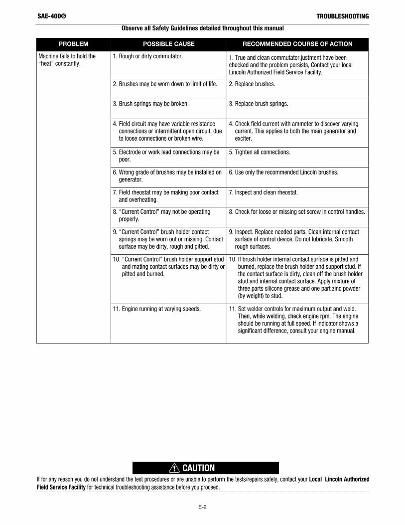
Machine fails to hold the“heat” constantly.
1. Rough or dirty commutator. 1. True and clean commutator.justment have beenchecked and the problem persists, Contact your localLincoln Authorized Field Service Facility.
2. Brushes may be worn down to limit of life. 2. Replace brushes.
3. Brush springs may be broken. 3. Replace brush springs.
4. Field circuit may have variable resistanceconnections or intermittent open circuit, dueto loose connections or broken wire.
4. Check field current with ammeter to discover varyingcurrent. This applies to both the main generator andexciter.
5. Electrode or work lead connections may bepoor.
5. Tighten all connections.
6. Wrong grade of brushes may be installed ongenerator.
6. Use only the recommended Lincoln brushes.
7. Field rheostat may be making poor contactand overheating.
7. Inspect and clean rheostat.
8. “Current Control” may not be operatingproperly.
8. Check for loose or missing set screw in control handles.
9. “Current Control” brush holder contactsprings may be worn out or missing. Contactsurface may be dirty, rough and pitted.
9. Inspect. Replace needed parts. Clean internal contactsurface of control device. Do not lubricate. Smoothrough surfaces.
10. “Current Control” brush holder support studand mating contact surfaces may be dirty orpitted and burned.
10. If brush holder internal contact surface is pitted andburned, replace the brush holder and support stud. Ifthe contact surface is dirty, clean off the brush holderstud and internal contact surface. Apply mixture ofthree parts silicone grease and one part zinc powder(by weight) to stud.
11. Engine running at varying speeds. 11. Set welder controls for maximum output and weld.Then, while welding, check engine rpm. The engineshould be running at full speed. If indicator shows asignificant difference, consult your engine manual.
E-3
TROUBLESHOOTINGSAE-400®
Observe all Safety Guidelines detailed throughout this manual
If for any reason you do not understand the test procedures or are unable to perform the tests/repairs safely, contact your Local Lincoln AuthorizedField Service Facility for technical troubleshooting assistance before you proceed.
CAUTION
PROBLEM POSSIBLE CAUSE RECOMMENDED COURSE OF ACTION
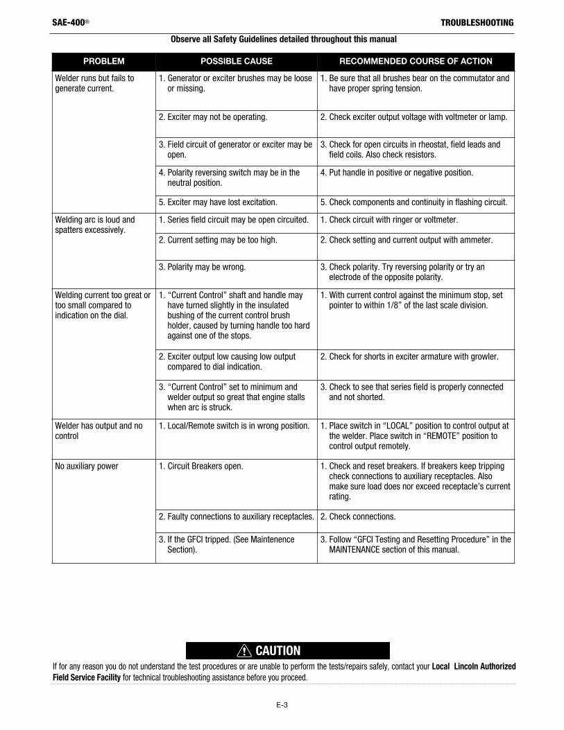
Welder runs but fails togenerate current.
1. Generator or exciter brushes may be looseor missing.
1. Be sure that all brushes bear on the commutator andhave proper spring tension.
2. Exciter may not be operating. 2. Check exciter output voltage with voltmeter or lamp.
3. Field circuit of generator or exciter may beopen.
3. Check for open circuits in rheostat, field leads andfield coils. Also check resistors.
4. Polarity reversing switch may be in theneutral position.
4. Put handle in positive or negative position.
5. Exciter may have lost excitation. 5. Check components and continuity in flashing circuit.
Welding arc is loud andspatters excessively.
1. Series field circuit may be open circuited. 1. Check circuit with ringer or voltmeter.
2. Current setting may be too high. 2. Check setting and current output with ammeter.
3. Polarity may be wrong. 3. Check polarity. Try reversing polarity or try anelectrode of the opposite polarity.
Welding current too great ortoo small compared toindication on the dial.
1. “Current Control” shaft and handle mayhave turned slightly in the insulatedbushing of the current control brushholder, caused by turning handle too hardagainst one of the stops.
1. With current control against the minimum stop, setpointer to within 1/8” of the last scale division.
2. Exciter output low causing low outputcompared to dial indication.
2. Check for shorts in exciter armature with growler.
3. “Current Control” set to minimum andwelder output so great that engine stallswhen arc is struck.
3. Check to see that series field is properly connectedand not shorted.
Welder has output and nocontrol
1. Local/Remote switch is in wrong position. 1. Place switch in “LOCAL” position to control output atthe welder. Place switch in “REMOTE” position tocontrol output remotely.
No auxiliary power 1. Circuit Breakers open. 1. Check and reset breakers. If breakers keep trippingcheck connections to auxiliary receptacles. Alsomake sure load does nor exceed receptacle’s currentrating.
2. Faulty connections to auxiliary receptacles. 2. Check connections.
3. If the GFCI tripped. (See MaintenenceSection).
3. Follow “GFCI Testing and Resetting Procedure” in theMAINTENANCE section of this manual.
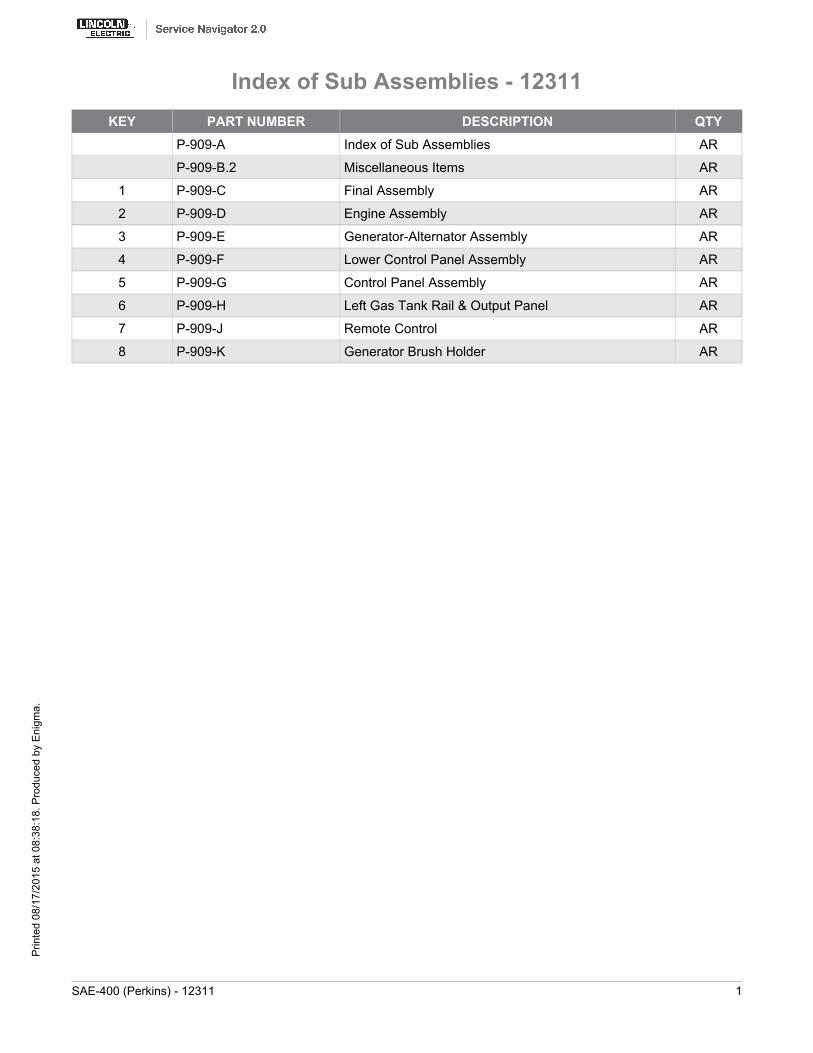
KEY PART NUMBER DESCRIPTION QTYP-909-A Index of Sub Assemblies AR
P-909-B.2 Miscellaneous Items AR
1 P-909-C Final Assembly AR
2 P-909-D Engine Assembly AR
3 P-909-E Generator-Alternator Assembly AR
4 P-909-F Lower Control Panel Assembly AR
5 P-909-G Control Panel Assembly AR
6 P-909-H Left Gas Tank Rail & Output Panel AR
7 P-909-J Remote Control AR
8 P-909-K Generator Brush Holder AR
Index of Sub Assemblies - 12311
SAE-400 (Perkins) - 12311 1
Prin
ted
08/1
7/20
15 a
t 08:
38:1
8. P
rodu
ced
by E
nigm
a.
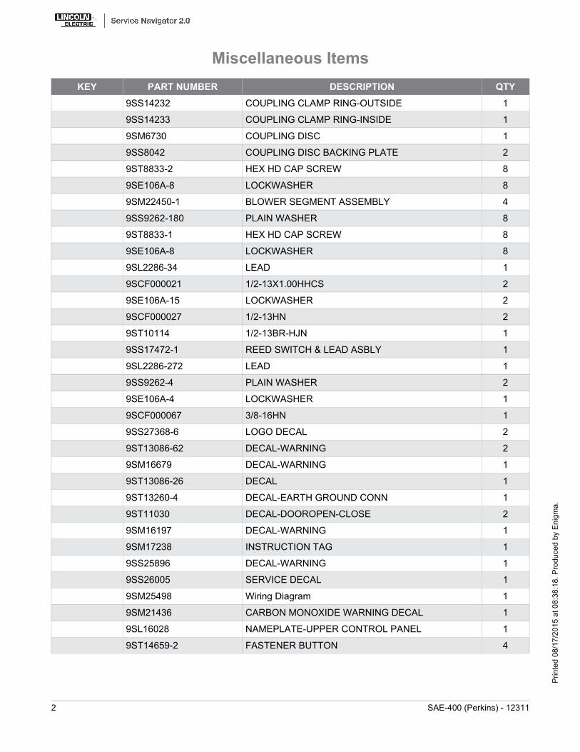
KEY PART NUMBER DESCRIPTION QTY9SS14232 COUPLING CLAMP RING-OUTSIDE 1
9SS14233 COUPLING CLAMP RING-INSIDE 1
9SM6730 COUPLING DISC 1
9SS8042 COUPLING DISC BACKING PLATE 2
9ST8833-2 HEX HD CAP SCREW 8
9SE106A-8 LOCKWASHER 8
9SM22450-1 BLOWER SEGMENT ASSEMBLY 4
9SS9262-180 PLAIN WASHER 8
9ST8833-1 HEX HD CAP SCREW 8
9SE106A-8 LOCKWASHER 8
9SL2286-34 LEAD 1
9SCF000021 1/2-13X1.00HHCS 2
9SE106A-15 LOCKWASHER 2
9SCF000027 1/2-13HN 2
9ST10114 1/2-13BR-HJN 1
9SS17472-1 REED SWITCH & LEAD ASBLY 1
9SL2286-272 LEAD 1
9SS9262-4 PLAIN WASHER 2
9SE106A-4 LOCKWASHER 1
9SCF000067 3/8-16HN 1
9SS27368-6 LOGO DECAL 2
9ST13086-62 DECAL-WARNING 2
9SM16679 DECAL-WARNING 1
9ST13086-26 DECAL 1
9ST13260-4 DECAL-EARTH GROUND CONN 1
9ST11030 DECAL-DOOROPEN-CLOSE 2
9SM16197 DECAL-WARNING 1
9SM17238 INSTRUCTION TAG 1
9SS25896 DECAL-WARNING 1
9SS26005 SERVICE DECAL 1
9SM25498 Wiring Diagram 1
9SM21436 CARBON MONOXIDE WARNING DECAL 1
9SL16028 NAMEPLATE-UPPER CONTROL PANEL 1
9ST14659-2 FASTENER BUTTON 4
Miscellaneous Items
2 SAE-400 (Perkins) - 12311
Prin
ted
08/1
7/20
15 a
t 08:
38:1
8. P
rodu
ced
by E
nigm
a.

KEY PART NUMBER DESCRIPTION QTY9SS29243 DECAL ENGINE CIRCUIT BREAKER 1
Miscellaneous Items
SAE-400 (Perkins) - 12311 3
Prin
ted
08/1
7/20
15 a
t 08:
38:1
8. P
rodu
ced
by E
nigm
a.

No Image
Miscellaneous Items
4 SAE-400 (Perkins) - 12311
Prin
ted
08/1
7/20
15 a
t 08:
38:1
8. P
rodu
ced
by E
nigm
a.

KEY PART NUMBER DESCRIPTION QTY1 9SL5519-1 BASE WELDED ASBLY 1
3 9SS9563-4 RAIN CAP 1
9SS17187-8 BATTERY CABLE 1
9ST14815-5 METRIC HEX NUT-M10 X 1.5- BRASS 1
9ST14815-4 METRIC HEX NUT-M5 X 0.8 1
9SS18385-1 METRIC LOCKWASHER - M5 1
9 9SS17187-9 BATTERY CABLE 2
9SCF000034 3/8-16X.75HHCS 1
9SE106A-16 LOCKWASHER 4
9SCF000067 3/8-16HN 4
9SS8070-58 Battery Cable Jumper 1
9SE106A-24 WASHER 5/16 LOCK (SS) 1
9SCF000028 5/16-18X1.25HHCS 2
9SCF000029 5/16-18HN 2
10 9SM9399-4 Battery 2
9ST14654 CAP-PLASTIC 2
9SS16931-4 BATTERY CLAMP BRACKET 1
9ST8818-3 BATTERY CLAMP HOOK 2
9SE106A-3 LOCKWASHER 2
9SCF000029 5/16-18HN 2
11 9SM8237-13 REAR SUPPORT ASBLY 1
9ST9860-4 LOCKWASHER 4
9SS9225-28 THREAD FORMING SCREW 4
15 9SM8889-3 LIFT BALE ASBLY 1
9ST8833-24 HEX HD CAP SCREW 4
9SE106A-15 LOCKWASHER 1
9SCF000027 1/2-13HN 1
17 9SS12934-2 COVER SEAL 1
18 9SM12005-6 SIDE RAIL 1
9SCF000030 1/2-13X1.25HHCS 1
9SS9262-1 PLAIN WASHER 1
9SE106A-15 LOCKWASHER 1
9SCF000027 1/2-13HN 1
9SCF000030 1/2-13X1.25HHCS 1
Final Assembly
SAE-400 (Perkins) - 12311 5
Prin
ted
08/1
7/20
15 a
t 08:
38:1
8. P
rodu
ced
by E
nigm
a.
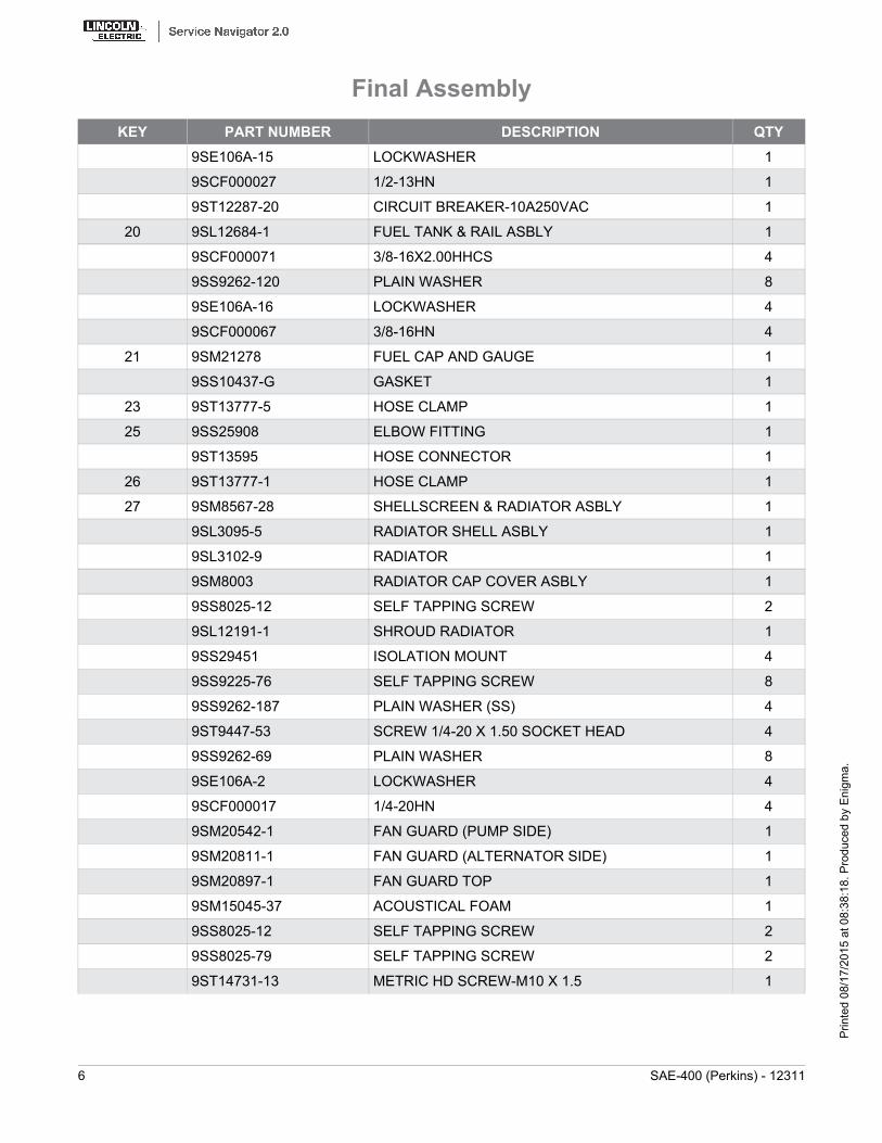
KEY PART NUMBER DESCRIPTION QTY9SE106A-15 LOCKWASHER 1
9SCF000027 1/2-13HN 1
9ST12287-20 CIRCUIT BREAKER-10A250VAC 1
20 9SL12684-1 FUEL TANK & RAIL ASBLY 1
9SCF000071 3/8-16X2.00HHCS 4
9SS9262-120 PLAIN WASHER 8
9SE106A-16 LOCKWASHER 4
9SCF000067 3/8-16HN 4
21 9SM21278 FUEL CAP AND GAUGE 1
9SS10437-G GASKET 1
23 9ST13777-5 HOSE CLAMP 1
25 9SS25908 ELBOW FITTING 1
9ST13595 HOSE CONNECTOR 1
26 9ST13777-1 HOSE CLAMP 1
27 9SM8567-28 SHELLSCREEN & RADIATOR ASBLY 1
9SL3095-5 RADIATOR SHELL ASBLY 1
9SL3102-9 RADIATOR 1
9SM8003 RADIATOR CAP COVER ASBLY 1
9SS8025-12 SELF TAPPING SCREW 2
9SL12191-1 SHROUD RADIATOR 1
9SS29451 ISOLATION MOUNT 4
9SS9225-76 SELF TAPPING SCREW 8
9SS9262-187 PLAIN WASHER (SS) 4
9ST9447-53 SCREW 1/4-20 X 1.50 SOCKET HEAD 4
9SS9262-69 PLAIN WASHER 8
9SE106A-2 LOCKWASHER 4
9SCF000017 1/4-20HN 4
9SM20542-1 FAN GUARD (PUMP SIDE) 1
9SM20811-1 FAN GUARD (ALTERNATOR SIDE) 1
9SM20897-1 FAN GUARD TOP 1
9SM15045-37 ACOUSTICAL FOAM 1
9SS8025-12 SELF TAPPING SCREW 2
9SS8025-79 SELF TAPPING SCREW 2
9ST14731-13 METRIC HD SCREW-M10 X 1.5 1
Final Assembly
6 SAE-400 (Perkins) - 12311
Prin
ted
08/1
7/20
15 a
t 08:
38:1
8. P
rodu
ced
by E
nigm
a.

KEY PART NUMBER DESCRIPTION QTY9SS17400-1 LOCKWASHER-METRIC 1
30 9SM20281 AIR FILTER 1
9SM20282 MOUNTING BAND 1
9SCF000028 5/16-18X1.25HHCS 2
9SE106A-3 LOCKWASHER 2
9SS9262-121 PLAIN WASHER 4
9SCF000029 5/16-18HN 2
31 9SL12351 AIR INTAKE HOSE 1
9SS10888-20 HOSE CLAMP 1
9SS10888-33 HOSE CLAMP 1
37 9SL3448-27 ROOF 1
38 9ST9428 ROOF MOUNTING ANGLE 2
9SCF000180 5/16-18X1.25SQHS-FULL-GR2-1817/1 2
9ST9187 LOCKNUT 2
39 9ST8818 ROOF HOOK 2
9ST9187 LOCKNUT 2
9ST15154 DOOR BUMPER 8
41 9SL3319-C DOOR 4
42 9SS20295 DOOR HINGE PIN 8
9SS9776-62 RETAINING RING 1
9SS21463 DOOR BUMPER 1
9SS9262-98 PLAIN WASHER 1
9SM8834-1 RIVET 1
9ST10982-7 SPEED CLIP 1
9SS10656-1 DOOR HOOK ASBLY 4
9ST10878 WASHER 4
9SS8025-92 SELF TAPPING SCREW 8
9SS10656-2 DOOR HOOK ASBLY 4
9ST10878 WASHER 4
9SS8025-92 SELF TAPPING SCREW 8
54 9SS25474 DOOR RESTRAINT ASBLY 1
9SS24739-2 MISC STAINLESS STEEL SCREW 2
9SS9262-174 PLAIN WASHER (SS) 2
9SE106A-22 WASHER #10 LOCK (SS) 1
Final Assembly
SAE-400 (Perkins) - 12311 7
Prin
ted
08/1
7/20
15 a
t 08:
38:1
8. P
rodu
ced
by E
nigm
a.

KEY PART NUMBER DESCRIPTION QTY9SCF000393 #10-24SS-HN 1
9SS20290 SPRING CLIP 1
9SS24739-29 #10-24X.38RHS-FULL-SS 1
9SS9262-174 PLAIN WASHER (SS) 2
9SE106A-22 WASHER #10 LOCK (SS) 1
9SCF000393 #10-24SS-HN 1
9SM18959-2 BREAKER & RECEPTACLE GUARD ASBLY 1
9SS9225-68 THREAD FORMING SCREW (CUTTING) 2
Final Assembly
8 SAE-400 (Perkins) - 12311
Prin
ted
08/1
7/20
15 a
t 08:
38:1
8. P
rodu
ced
by E
nigm
a.
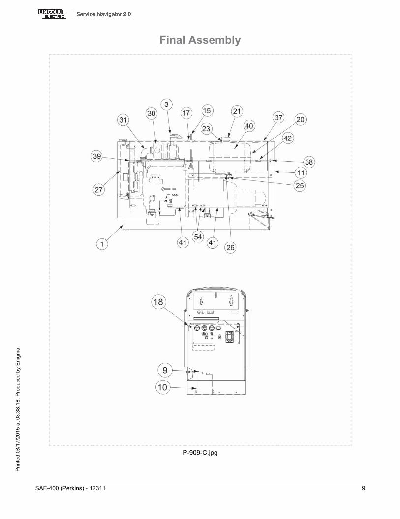
P-909-C.jpg
Final Assembly
SAE-400 (Perkins) - 12311 9
Prin
ted
08/1
7/20
15 a
t 08:
38:1
8. P
rodu
ced
by E
nigm
a.
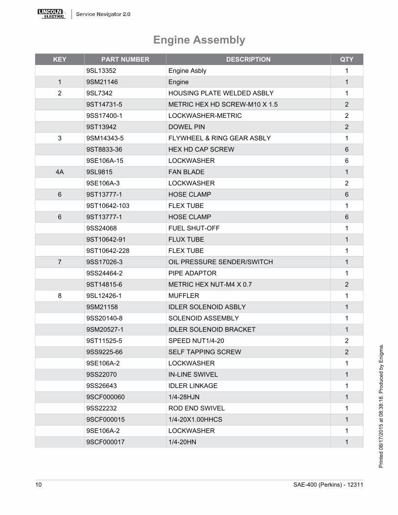
KEY PART NUMBER DESCRIPTION QTY9SL13352 Engine Asbly 1
1 9SM21146 Engine 1
2 9SL7342 HOUSING PLATE WELDED ASBLY 1
9ST14731-5 METRIC HEX HD SCREW-M10 X 1.5 2
9SS17400-1 LOCKWASHER-METRIC 2
9ST13942 DOWEL PIN 2
3 9SM14343-5 FLYWHEEL & RING GEAR ASBLY 1
9ST8833-36 HEX HD CAP SCREW 6
9SE106A-15 LOCKWASHER 6
4A 9SL9815 FAN BLADE 1
9SE106A-3 LOCKWASHER 2
6 9ST13777-1 HOSE CLAMP 6
9ST10642-103 FLEX TUBE 1
6 9ST13777-1 HOSE CLAMP 6
9SS24068 FUEL SHUT-OFF 1
9ST10642-91 FLUX TUBE 1
9ST10642-228 FLEX TUBE 1
7 9SS17026-3 OIL PRESSURE SENDER/SWITCH 1
9SS24464-2 PIPE ADAPTOR 1
9ST14815-6 METRIC HEX NUT-M4 X 0.7 2
8 9SL12426-1 MUFFLER 1
9SM21158 IDLER SOLENOID ASBLY 1
9SS20140-8 SOLENOID ASSEMBLY 1
9SM20527-1 IDLER SOLENOID BRACKET 1
9ST11525-5 SPEED NUT1/4-20 2
9SS9225-66 SELF TAPPING SCREW 2
9SE106A-2 LOCKWASHER 1
9SS22070 IN-LINE SWIVEL 1
9SS26643 IDLER LINKAGE 1
9SCF000060 1/4-28HJN 1
9SS22232 ROD END SWIVEL 1
9SCF000015 1/4-20X1.00HHCS 1
9SE106A-2 LOCKWASHER 1
9SCF000017 1/4-20HN 1
Engine Assembly
10 SAE-400 (Perkins) - 12311
Prin
ted
08/1
7/20
15 a
t 08:
38:1
8. P
rodu
ced
by E
nigm
a.
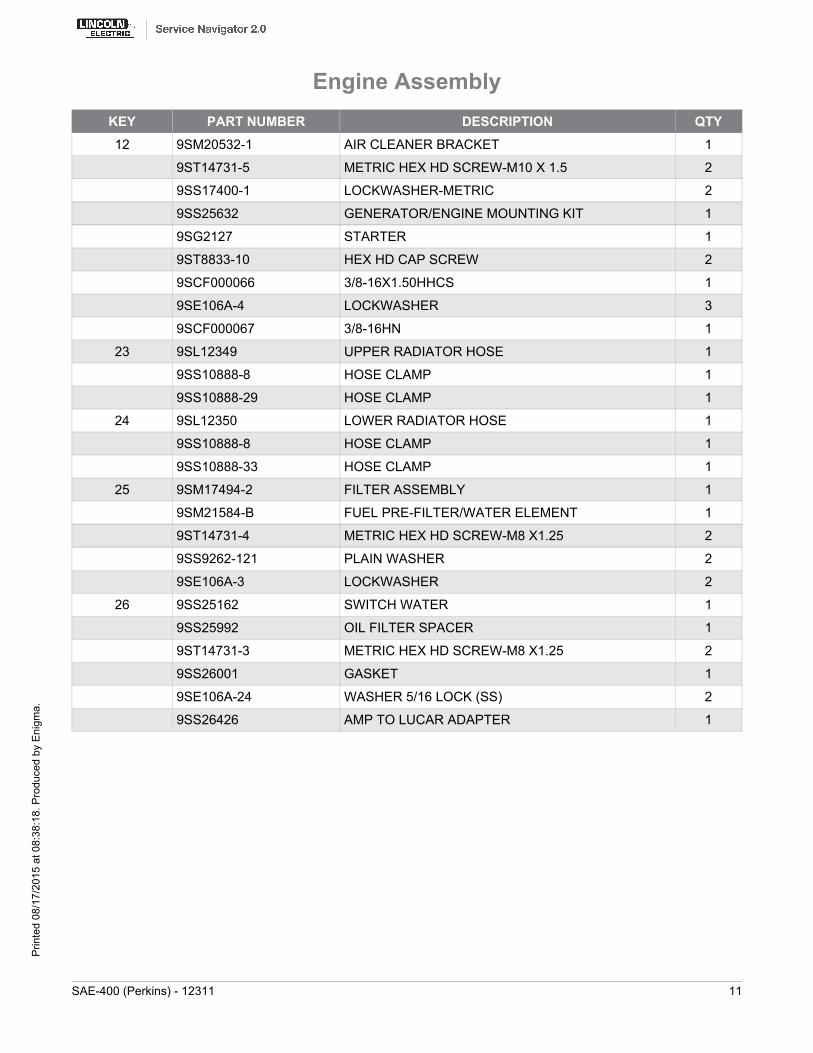
KEY PART NUMBER DESCRIPTION QTY12 9SM20532-1 AIR CLEANER BRACKET 1
9ST14731-5 METRIC HEX HD SCREW-M10 X 1.5 2
9SS17400-1 LOCKWASHER-METRIC 2
9SS25632 GENERATOR/ENGINE MOUNTING KIT 1
9SG2127 STARTER 1
9ST8833-10 HEX HD CAP SCREW 2
9SCF000066 3/8-16X1.50HHCS 1
9SE106A-4 LOCKWASHER 3
9SCF000067 3/8-16HN 1
23 9SL12349 UPPER RADIATOR HOSE 1
9SS10888-8 HOSE CLAMP 1
9SS10888-29 HOSE CLAMP 1
24 9SL12350 LOWER RADIATOR HOSE 1
9SS10888-8 HOSE CLAMP 1
9SS10888-33 HOSE CLAMP 1
25 9SM17494-2 FILTER ASSEMBLY 1
9SM21584-B FUEL PRE-FILTER/WATER ELEMENT 1
9ST14731-4 METRIC HEX HD SCREW-M8 X1.25 2
9SS9262-121 PLAIN WASHER 2
9SE106A-3 LOCKWASHER 2
26 9SS25162 SWITCH WATER 1
9SS25992 OIL FILTER SPACER 1
9ST14731-3 METRIC HEX HD SCREW-M8 X1.25 2
9SS26001 GASKET 1
9SE106A-24 WASHER 5/16 LOCK (SS) 2
9SS26426 AMP TO LUCAR ADAPTER 1
Engine Assembly
SAE-400 (Perkins) - 12311 11
Prin
ted
08/1
7/20
15 a
t 08:
38:1
8. P
rodu
ced
by E
nigm
a.
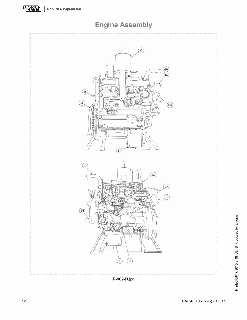
P-909-D.jpg
Engine Assembly
12 SAE-400 (Perkins) - 12311
Prin
ted
08/1
7/20
15 a
t 08:
38:1
8. P
rodu
ced
by E
nigm
a.
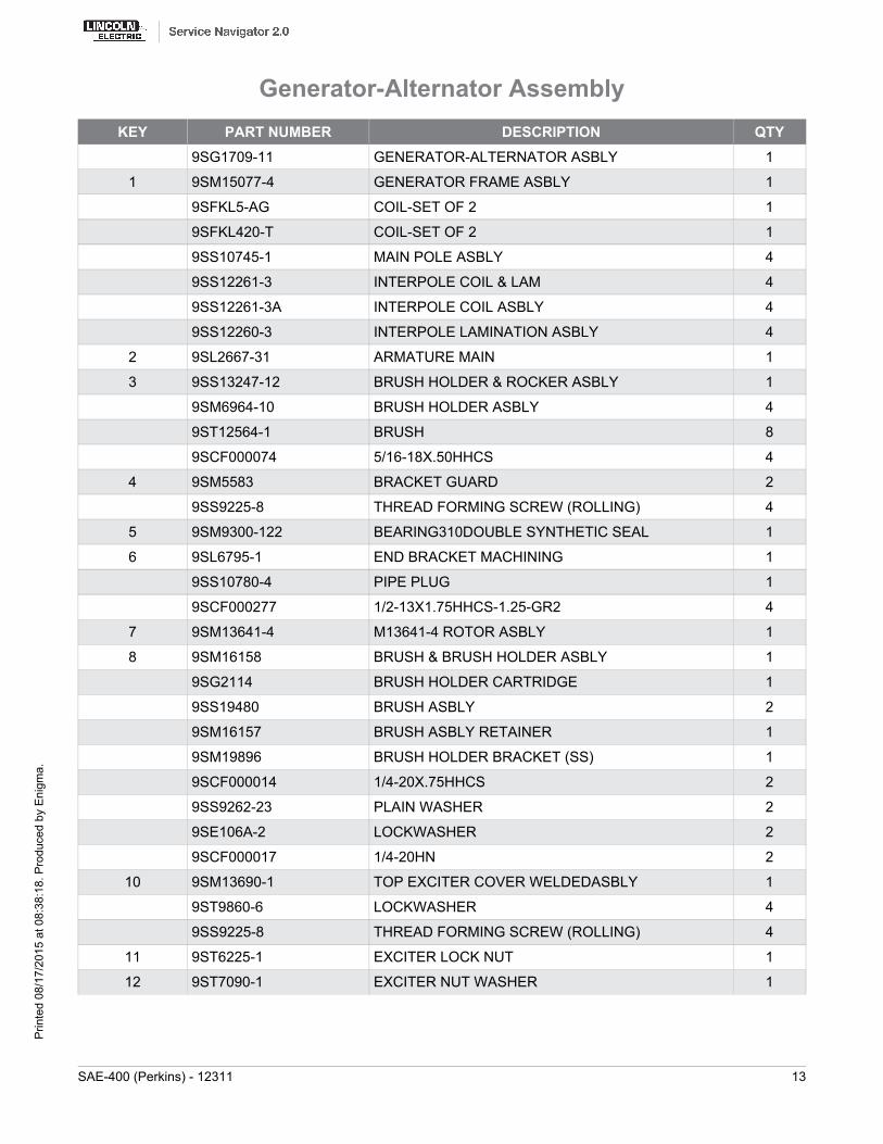
KEY PART NUMBER DESCRIPTION QTY9SG1709-11 GENERATOR-ALTERNATOR ASBLY 1
1 9SM15077-4 GENERATOR FRAME ASBLY 1
9SFKL5-AG COIL-SET OF 2 1
9SFKL420-T COIL-SET OF 2 1
9SS10745-1 MAIN POLE ASBLY 4
9SS12261-3 INTERPOLE COIL & LAM 4
9SS12261-3A INTERPOLE COIL ASBLY 4
9SS12260-3 INTERPOLE LAMINATION ASBLY 4
2 9SL2667-31 ARMATURE MAIN 1
3 9SS13247-12 BRUSH HOLDER & ROCKER ASBLY 1
9SM6964-10 BRUSH HOLDER ASBLY 4
9ST12564-1 BRUSH 8
9SCF000074 5/16-18X.50HHCS 4
4 9SM5583 BRACKET GUARD 2
9SS9225-8 THREAD FORMING SCREW (ROLLING) 4
5 9SM9300-122 BEARING310DOUBLE SYNTHETIC SEAL 1
6 9SL6795-1 END BRACKET MACHINING 1
9SS10780-4 PIPE PLUG 1
9SCF000277 1/2-13X1.75HHCS-1.25-GR2 4
7 9SM13641-4 M13641-4 ROTOR ASBLY 1
8 9SM16158 BRUSH & BRUSH HOLDER ASBLY 1
9SG2114 BRUSH HOLDER CARTRIDGE 1
9SS19480 BRUSH ASBLY 2
9SM16157 BRUSH ASBLY RETAINER 1
9SM19896 BRUSH HOLDER BRACKET (SS) 1
9SCF000014 1/4-20X.75HHCS 2
9SS9262-23 PLAIN WASHER 2
9SE106A-2 LOCKWASHER 2
9SCF000017 1/4-20HN 2
10 9SM13690-1 TOP EXCITER COVER WELDEDASBLY 1
9ST9860-6 LOCKWASHER 4
9SS9225-8 THREAD FORMING SCREW (ROLLING) 4
11 9ST6225-1 EXCITER LOCK NUT 1
12 9ST7090-1 EXCITER NUT WASHER 1
Generator-Alternator Assembly
SAE-400 (Perkins) - 12311 13
Prin
ted
08/1
7/20
15 a
t 08:
38:1
8. P
rodu
ced
by E
nigm
a.

KEY PART NUMBER DESCRIPTION QTY13 9ST14337 ARMATURE SLEEVE COLLAR 1
14 9SM13686 BOTTOM EXCITER COVER 1
9ST9860-6 LOCKWASHER 4
9SS9225-8 THREAD FORMING SCREW (ROLLING) 4
15 9SCF000067 3/8-16HN 1
Generator-Alternator Assembly
14 SAE-400 (Perkins) - 12311
Prin
ted
08/1
7/20
15 a
t 08:
38:1
8. P
rodu
ced
by E
nigm
a.
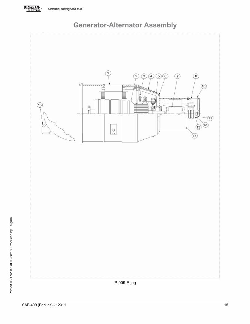
P-909-E.jpg
Generator-Alternator Assembly
SAE-400 (Perkins) - 12311 15
Prin
ted
08/1
7/20
15 a
t 08:
38:1
8. P
rodu
ced
by E
nigm
a.

KEY PART NUMBER DESCRIPTION QTY9SG8436 Lower Control Panel Assembly 1
1 9SL16774 Rear Lower Panel 1
2 9SL16780 Rear Panel Nameplate 1
9ST14659-2 FASTENER BUTTON 4
3 9SS20206 OIL PRESSURE GAUGE 1
4 9SS25154 WATER TEMPERATURE GAUGE 1
5 9SS7514-7 AMMETER 1
6 9SM22209 FUEL/HOUR METER 1
14 9ST10800-55 TOGGLE SWITCH 1
9SS22061-4 SEALING BOOT 1
10 9SS13146-4 SWITCH-PUSH BUTTON 1
11 9ST13534-3 PILOT LIGHT 1
12 9SM19120 SWITCH & RECEPTACLE ASBLY 1
9ST10800-56 SWITCHTOGGLEDPDT 1
9SS21012 RECEPTACLE 1
9SS9225-63 THREAD FORMING SCREW (CUTTING) 4
9ST11525-1 SPEED NUT#10-24 2
9SS22061-4 SEALING BOOT 1
13 9SS13146-1 START BUTTON 1
14 9ST10800-55 TOGGLE SWITCH 1
9SS22061-4 SEALING BOOT 1
15 9SS9225-36 THREAD FORMING SCREW (CUTTING) 1
9ST9695-1 LOCKWASHER 1
9SCF000010 #10-24HN 4
20 9SL12400-3V1 IDLER/ENGINE SHUTDOWN PC BD ASBLY 1
9SCF000149 #10-24X1.25RHS 4
9SS9262-27 PLAIN WASHER 4
9SE106A-1 LOCKWASHER 4
9SCF000010 #10-24HN 4
9SS18250-397 PLUG & LEAD ASBLY 1
9SG8186 Harness 1
25 9ST14659-1 FASTENER BUTTON 4
27 9SM20152-2 RECEPTACLE-115V 1
9SS9225-63 THREAD FORMING SCREW (CUTTING) 4
Lower Control Panel Assembly
16 SAE-400 (Perkins) - 12311
Prin
ted
08/1
7/20
15 a
t 08:
38:1
8. P
rodu
ced
by E
nigm
a.

KEY PART NUMBER DESCRIPTION QTY28 9SM20152-3 RECEPTACLE-230V 1
9SS9225-63 THREAD FORMING SCREW (CUTTING) 4
29 9SS28004-2 COVER PLATE 1
9SS9225-63 THREAD FORMING SCREW (CUTTING) 4
9SM22328 RECEPTACLE GUARD 1
9SS9225-63 THREAD FORMING SCREW (CUTTING) 4
9SS26843-1 GFCI REWORK 1
9SS28464 GFCI COVER 1
9SL13286 GFCI HOUSING 1
9SS27167 MOUNTING BRACKET 1
9SS24738-3 THERMOPLASTIC SCREW 2
Lower Control Panel Assembly
SAE-400 (Perkins) - 12311 17
Prin
ted
08/1
7/20
15 a
t 08:
38:1
8. P
rodu
ced
by E
nigm
a.
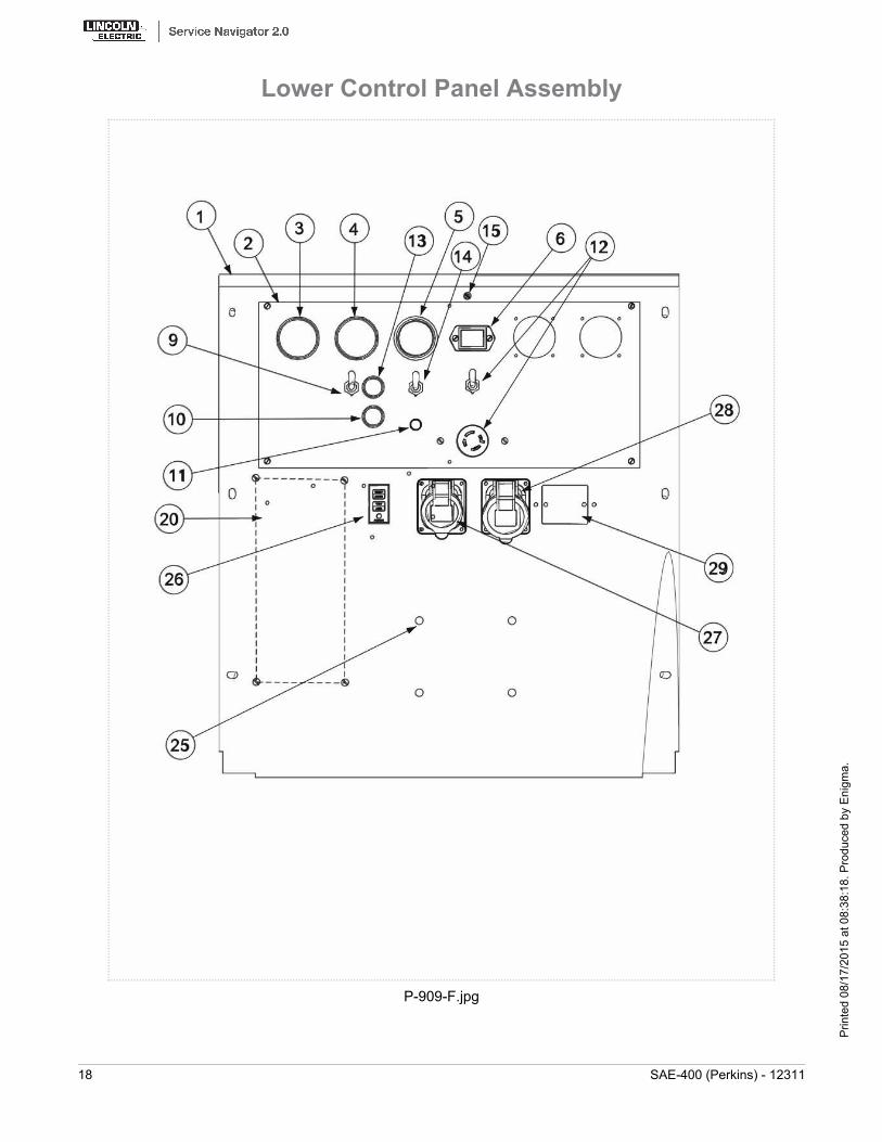
P-909-F.jpg
Lower Control Panel Assembly
18 SAE-400 (Perkins) - 12311
Prin
ted
08/1
7/20
15 a
t 08:
38:1
8. P
rodu
ced
by E
nigm
a.

KEY PART NUMBER DESCRIPTION QTY9SL13089-3 Control Panel Asbly 1
1 9SM17602-7 REACTOR BOX & CONTROL PANEL ASBLY 1
2 9SS16664-9 CONTROL HANDLE ASBLY 1
5 9SM7057-1 REVERSING SWITCH ASBLY 1
9SS8025-22 SELF TAPPING SCREW 2
6 9SM5090-C RHEOSTAT 1
7 9ST10082-4 SEMS SCREW 2
8 9SS16664-13 CONTROL HANDLE ASBLY 1
9 9ST7852 BRUSH HOLDER STUD ASBLY 1
9SS9225-8 THREAD FORMING SCREW (ROLLING) 4
10 9SM6277 BRUSH HOLDER ASBLY 1
9SM6264 BRUSH HOLDER 1
9ST6985 SPRING 4
9SE106A-1 LOCKWASHER 1
9SCF000061 SCREW #10-24X.375RHS 4
9ST7494 BRUSH CONTACT SPRING ASBLY 4
9ST8218 SHAFT 1
9ST8219 INSULATING TUBE 1
9SCF000062 5/16-18X1.00HHCS 2
11 9SS7297 REACTOR SPRING CLIP 1
12 9SS9262-41 PLAIN WASHER 1
13 9ST8236 SPRING 1
14 9SL2036-B REACTOR 1
9SS9225-8 THREAD FORMING SCREW (ROLLING) 4
15 9ST8280 RESISTOR-WIREWOUND 1
9SCF000045 #10-24X5.00RHS 1
9SE106A-1 LOCKWASHER 1
9SCF000010 #10-24HN 1
16 9ST13339 CAUTION DECAL 1
17 9ST13637 SILICON BRIDGE ASBLY 3
9SCF000059 #8-32X.875RHS 3
9SS9262-3 PLAIN WASHER 4
9ST4291-A LOCKWASHER 4
9SCF000042 #8-32HN 3
Control Panel Assembly
SAE-400 (Perkins) - 12311 19
Prin
ted
08/1
7/20
15 a
t 08:
38:1
8. P
rodu
ced
by E
nigm
a.
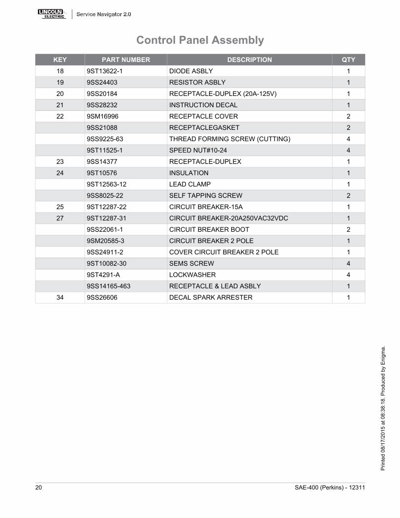
KEY PART NUMBER DESCRIPTION QTY18 9ST13622-1 DIODE ASBLY 1
19 9SS24403 RESISTOR ASBLY 1
20 9SS20184 RECEPTACLE-DUPLEX (20A-125V) 1
21 9SS28232 INSTRUCTION DECAL 1
22 9SM16996 RECEPTACLE COVER 2
9SS21088 RECEPTACLEGASKET 2
9SS9225-63 THREAD FORMING SCREW (CUTTING) 4
9ST11525-1 SPEED NUT#10-24 4
23 9SS14377 RECEPTACLE-DUPLEX 1
24 9ST10576 INSULATION 1
9ST12563-12 LEAD CLAMP 1
9SS8025-22 SELF TAPPING SCREW 2
25 9ST12287-22 CIRCUIT BREAKER-15A 1
27 9ST12287-31 CIRCUIT BREAKER-20A250VAC32VDC 1
9SS22061-1 CIRCUIT BREAKER BOOT 2
9SM20585-3 CIRCUIT BREAKER 2 POLE 1
9SS24911-2 COVER CIRCUIT BREAKER 2 POLE 1
9ST10082-30 SEMS SCREW 4
9ST4291-A LOCKWASHER 4
9SS14165-463 RECEPTACLE & LEAD ASBLY 1
34 9SS26606 DECAL SPARK ARRESTER 1
Control Panel Assembly
20 SAE-400 (Perkins) - 12311
Prin
ted
08/1
7/20
15 a
t 08:
38:1
8. P
rodu
ced
by E
nigm
a.
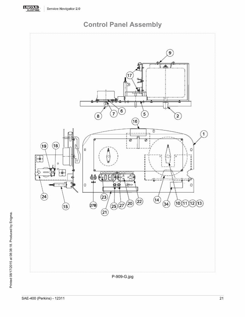
P-909-G.jpg
Control Panel Assembly
SAE-400 (Perkins) - 12311 21
Prin
ted
08/1
7/20
15 a
t 08:
38:1
8. P
rodu
ced
by E
nigm
a.
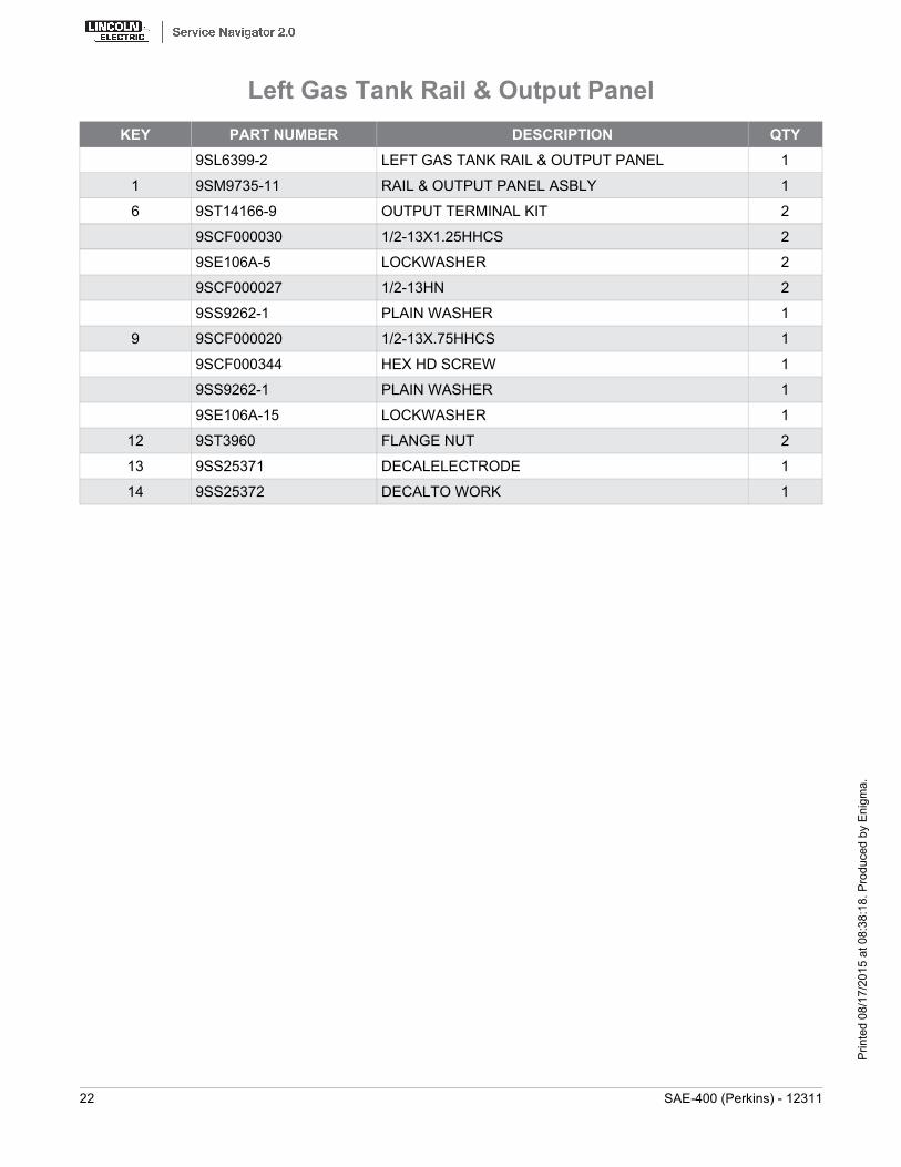
KEY PART NUMBER DESCRIPTION QTY9SL6399-2 LEFT GAS TANK RAIL & OUTPUT PANEL 1
1 9SM9735-11 RAIL & OUTPUT PANEL ASBLY 1
6 9ST14166-9 OUTPUT TERMINAL KIT 2
9SCF000030 1/2-13X1.25HHCS 2
9SE106A-5 LOCKWASHER 2
9SCF000027 1/2-13HN 2
9SS9262-1 PLAIN WASHER 1
9 9SCF000020 1/2-13X.75HHCS 1
9SCF000344 HEX HD SCREW 1
9SS9262-1 PLAIN WASHER 1
9SE106A-15 LOCKWASHER 1
12 9ST3960 FLANGE NUT 2
13 9SS25371 DECALELECTRODE 1
14 9SS25372 DECALTO WORK 1
Left Gas Tank Rail & Output Panel
22 SAE-400 (Perkins) - 12311
Prin
ted
08/1
7/20
15 a
t 08:
38:1
8. P
rodu
ced
by E
nigm
a.
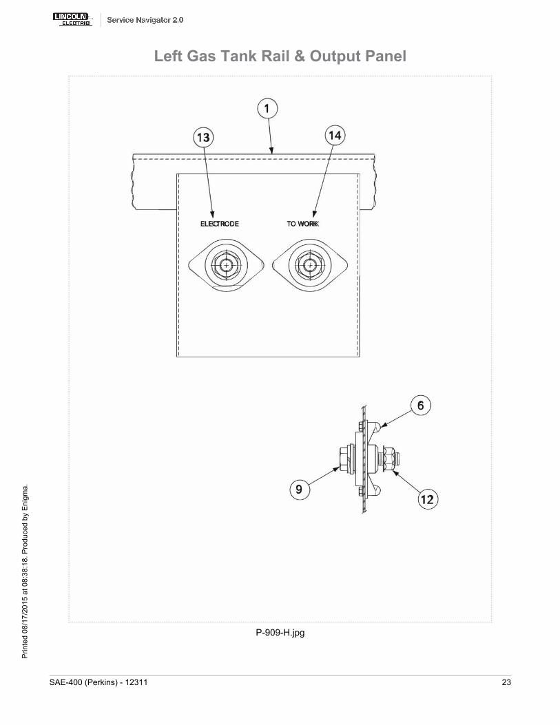
P-909-H.jpg
Left Gas Tank Rail & Output Panel
SAE-400 (Perkins) - 12311 23
Prin
ted
08/1
7/20
15 a
t 08:
38:1
8. P
rodu
ced
by E
nigm
a.

KEY PART NUMBER DESCRIPTION QTY9SL9303-1 FINAL ASBLY-REMOTE CONTROL 1
1 9SL9253 CONTROL BOX 1
2 9SL9252 WRAPAROUND 1
9SS8025-91 SELF TAPPING SCREW 4
3 9SL9254 HANDLE MTG BRKT 1
9SS8025-91 SELF TAPPING SCREW 4
4 9SM15446 HANDLE 1
9SS9225-53 THREAD FORMING SCREW 2
5 9SM5090-C RHEOSTAT 1
9SCF000170 1/4-20X.375HHB 2
9SE106A-2 LOCKWASHER 1
6 9SS16664-13 CONTROL HANDLE ASBLY 1
7 9SM17267 NAMEPLATE-REMOTE CONTROL 1
9SS9225-30 THREAD FORMING SCREW (CUTTING) 1
9ST9695-1 LOCKWASHER 1
9SCF000010 #10-24HN 3
9 9ST9639-2 BOX CONNECTOR 1
10 9SS21007 CABLE ASBLY 1
9SCF000102 #8-32X.50BR-RHS 6
9SCF000103 #8-32BR-HN 1
11 9SM17285 RESISTOR BANK ASBLY 1
9SS21009 RESISTOR MTG BRKT 2
9SS10404-22 RESISTOR-WIREWOUND 3
9SCF000045 #10-24X5.00RHS 3
9ST4479-A INSULATING WASHER 3
9SE106A-1 LOCKWASHER 3
9SCF000010 #10-24HN 3
9SCF000102 #8-32X.50BR-RHS 6
9SCF000103 #8-32BR-HN 1
9SS8025-92 SELF TAPPING SCREW 2
Remote Control
24 SAE-400 (Perkins) - 12311
Prin
ted
08/1
7/20
15 a
t 08:
38:1
8. P
rodu
ced
by E
nigm
a.
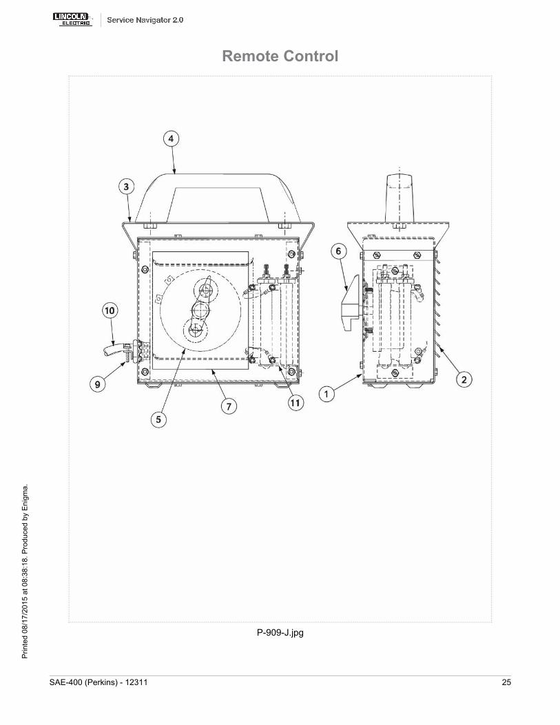
P-909-J.jpg
Remote Control
SAE-400 (Perkins) - 12311 25
Prin
ted
08/1
7/20
15 a
t 08:
38:1
8. P
rodu
ced
by E
nigm
a.
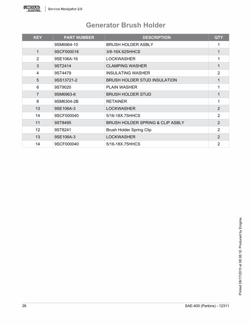
KEY PART NUMBER DESCRIPTION QTY9SM6964-10 BRUSH HOLDER ASBLY 1
1 9SCF000018 3/8-16X.625HHCS 1
2 9SE106A-16 LOCKWASHER 1
3 9ST2414 CLAMPING WASHER 1
4 9ST4479 INSULATING WASHER 2
5 9SS13721-2 BRUSH HOLDER STUD INSULATION 1
6 9ST9020 PLAIN WASHER 1
7 9SM6963-6 BRUSH HOLDER STUD 1
8 9SM6304-2B RETAINER 1
13 9SE106A-3 LOCKWASHER 2
14 9SCF000040 5/16-18X.75HHCS 2
11 9ST8495 BRUSH HOLDER SPRING & CLIP ASBLY 2
12 9ST8241 Brush Holder Spring Clip 2
13 9SE106A-3 LOCKWASHER 2
14 9SCF000040 5/16-18X.75HHCS 2
Generator Brush Holder
26 SAE-400 (Perkins) - 12311
Prin
ted
08/1
7/20
15 a
t 08:
38:1
8. P
rodu
ced
by E
nigm
a.
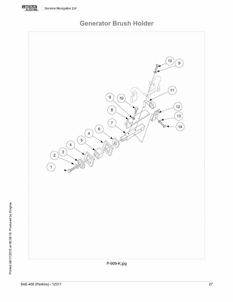
P-909-K.jpg
Generator Brush Holder
SAE-400 (Perkins) - 12311 27
Prin
ted
08/1
7/20
15 a
t 08:
38:1
8. P
rodu
ced
by E
nigm
a.
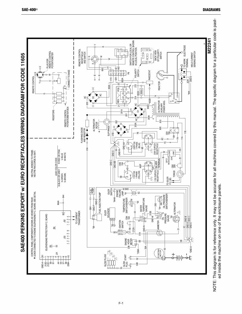
F-1
DIAGRAMSSAE-400®
NOTE
: This
diag
ram is for referen
ce only
. It m
ay not be accurate for a
ll machin
es co
vered by this man
ual. T
he sp
ecific
diag
ram for a
particula
r cod
e is pa
st-ed
insid
e the machin
e on
one
of the
enclos
ure pa
nels.
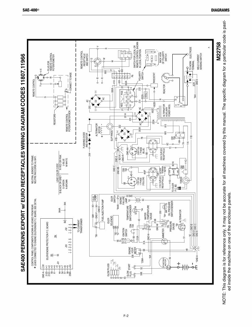
F-2
DIAGRAMSSAE-400®
NOTE
: This
diag
ram is for referen
ce only
. It m
ay not be accurate for a
ll machin
es co
vered by this man
ual. T
he sp
ecific
diag
ram for a
particula
r cod
e is pa
st-ed
insid
e the machin
e on
one
of the
enclos
ure pa
nels.
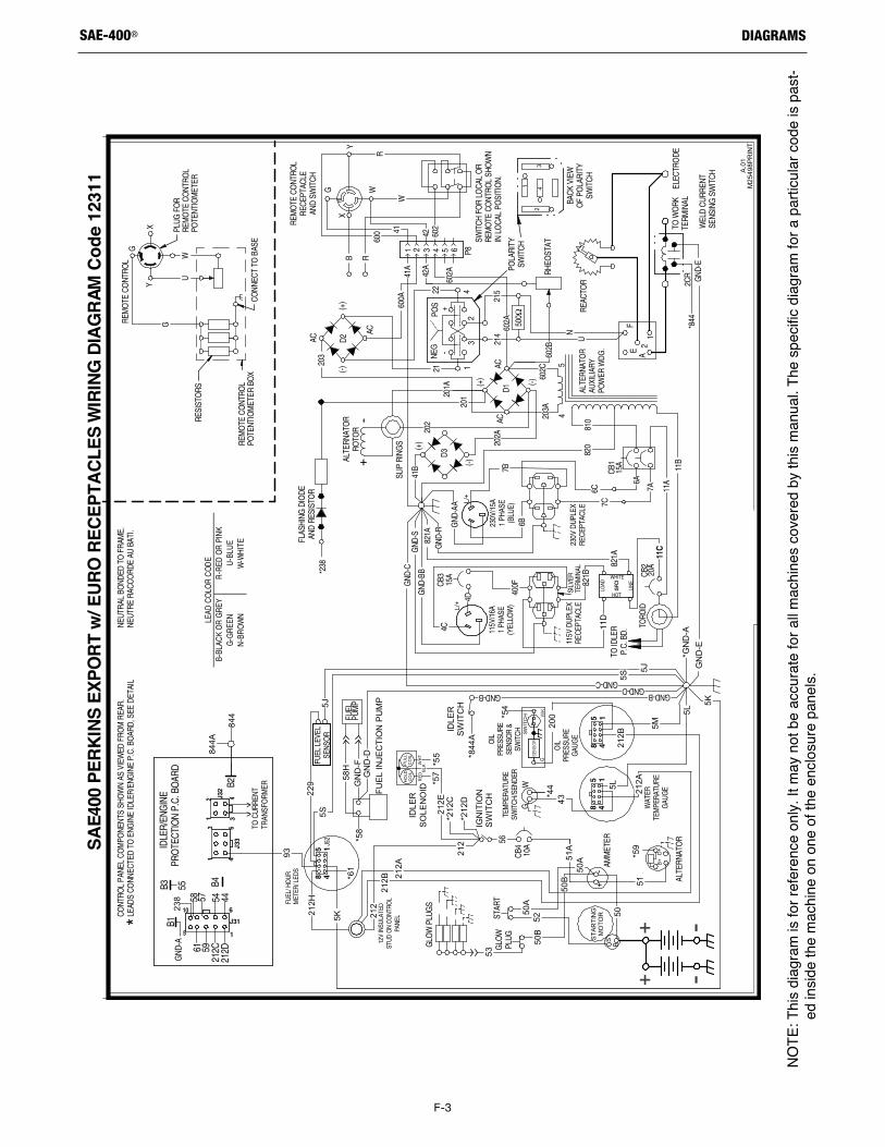
F-3
DIAGRAMSSAE-400®
AC
(-)D2
AC
202
1
(+)
AC
203
ACD1
A1
2
2CR
E
*844
GND
-E
602B
(-)
NEG
POS
TORO
ID
201
W
3
500 Ω
602A
-22
600A
Y
4
3
1
X
42
P8
215
+
W
2
11A
400F
6A
(+)
REAC
TOR
NU
F
54
ELEC
TRO
DE
B
600
R
R
41A
214
G
602
5 6
4243
41
21
42A
21
CB1
CB3 CB
2
201A
15A
20A
15A
NEUT
RAL
BOND
ED T
O F
RAM
E.NE
UTRE
RAC
CORD
E AU
BAT
I.CO
NTRO
L PA
NEL
COM
PONE
NTS
SHO
WN
AS V
IEW
ED F
ROM
REA
R.
TO ID
LER
P.C.
BD.
FLAS
HING
DIO
DEAN
D RE
SIST
OR
SLIP
RIN
GS
ALTE
RNAT
OR
ROTO
R
REM
OTE
CO
NTRO
LRE
CEPT
ACLE
AND
SWIT
CH
ALTE
RNAT
OR
AUXI
LIAR
YPO
WER
WDG
.
WEL
D CU
RREN
TSE
NSIN
G S
WIT
CH
SWIT
CH F
OR
LOCA
L O
RRE
MO
TE C
ONT
ROL
SHO
WN
IN L
OCA
L PO
SITI
ON.
BACK
VIE
WO
F PO
LARI
TYSW
ITCH
POLA
RITY
SWIT
CH
PLUG
FO
R RE
MO
TE C
ONT
ROL
POTE
NTIO
MET
ER
REM
OTE
CO
NTRO
LPO
TENT
IOM
ETER
BO
X
RESI
STO
RS
YX
U
G
W
G
11B
820
REM
OTE
CO
NTRO
L
GND
-SG
ND-B
B
GND
-R
602C
203A
CONN
ECT
TO B
ASE
B-BL
ACK
OR
GR
EYR
-RED
OR
PIN
KG
-GR
EEN
U-B
LUE
N-B
RO
WN
W-W
HIT
E
LEAD
CO
LOR
CO
DE
TO W
ORK
TERM
INAL
115V
DUP
LEX
RECE
PTAC
LE23
0V D
UPLE
XRE
CEPT
ACLE
-+
602A RH
EOST
AT
*LEAD
S CO
NNEC
TED
TO E
NGIN
E ID
LER/
ENG
INE
P.C.
BO
ARD,
SEE
DET
AIL
7A
810
11C
821B
11D
821A
230V
/15A
1 PH
ASE
(BLU
E)
L/+
(+)
D3
(-)
115V
/16A
1 PH
ASE
(YEL
LOW
)L/+
821A
GND
-AA
GND
-C
4C
202A
41B
6B
7B
4D
6C7C
SILV
ERTE
RMIN
AL
LIN
E
LOAD
GFC
I
HOT
WHITE
*238
844
844A
238
5L
5S
5J
212B
212A
41
85
41
85
5K
212
5K
12V
INSU
LATE
DST
UD O
N CO
NTRO
LPA
NEL
FUEL
LEV
ELSE
NSO
R4
18
5
FUEL
/ HO
URM
ETER
/ LED
S
J52
GND-D
GN
D-E
*60A
*54
*55
*57
53
50
50B
51A
50A
50A
50B
52
GND-B
GND-C
SWIT
CH
GW
KSE
NSOR
PU
LLC
OIL
HO
LDC
OIL
RE
DW
HT
FUEL
PUM
P
+ -
IDLE
RS
WIT
CH
STAR
TIN
GM
OTO
R
*844
A
GLO
W P
LUG
S
FUE
L IN
JEC
TIO
N P
UM
P
CB4
10A
*59
*61
*44
GLO
WPL
UG
WAT
ERTE
MPE
RATU
RE
GAU
GE
OIL
PRES
SURE
GAU
GE
OIL
PRES
SURE
SENS
OR
&SW
ITCH
TEM
PERA
TURE
SWIT
CH/S
ENDE
R
WG
BS
B+
ALTE
RNAT
OR
D+
-
IDLE
RS
OLE
NO
ID
AMM
ETER
+
STAR
T
212H
5K
229
212A
212B
212
5S5J
GN
D-F
GN
D-D
58H
*58
212E
200
43
51
GND-B
5L
5S
5J
212B
212A
212
5K
GND-D
GN
D-E
*GN
D-A
53
50
50B
51A
50A
50A
50B
52
GND-B
GND-C
56
5M
93
5L
BLK
*212
C*2
12D
IGN
ITIO
NS
WIT
CH
TO C
URRE
NTTR
ANSF
ORM
ER
GND
-A
58 57 54 44
61 5921
2C21
2DB4B3
B2
B1
I
DLER
/ENG
INE
PRO
TECT
ION
P.C.
BO
ARD
13 6
J33
4
J3115
10 6
12 4
3J3
2
>>
55
+ -
SAE4
00 P
ERKI
NS E
XPOR
T w/
EUR
O RE
CEPT
ACLE
S W
IRIN
G DI
AGRA
M C
ode
1231
1 A.01
M25
498P
RIN
T
NOTE
: This
diag
ram is for referen
ce only
. It m
ay not be accurate for a
ll machin
es co
vered by this man
ual. T
he sp
ecific
diag
ram for a
particula
r cod
e is pa
st-ed
insid
e the machin
e on
one
of the
enclos
ure pa
nels.
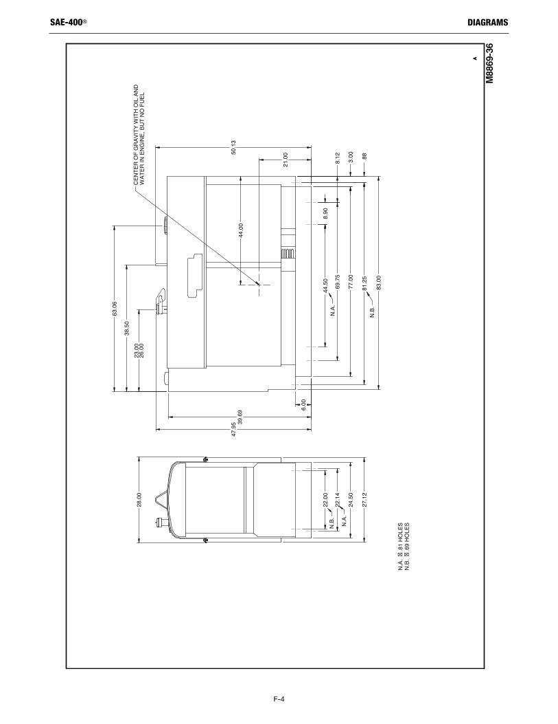
F-4
DIAGRAMSSAE-400®
M8869-36
AA
N.A.
�.8
1 HO
LES
N.B.
�.6
9 HO
LES
28.0
0
22.0
0
22.1
4
24.5
0
27.1
2
6.00
39.6
947
.95
23.0
026
.00
38.5
0
63.0
6
50.1
3
21.0
0
44.0
0
8.90
44.5
0
69.7
58.
12
77.0
03.
00
81.2
5.8
8
83.0
0
CENT
ER O
F GR
AVIT
Y W
ITH
OIL
AND
WAT
ER IN
ENG
INE,
BUT
NO
FUEL
N.A.
N.A.
N.B.
N.B.
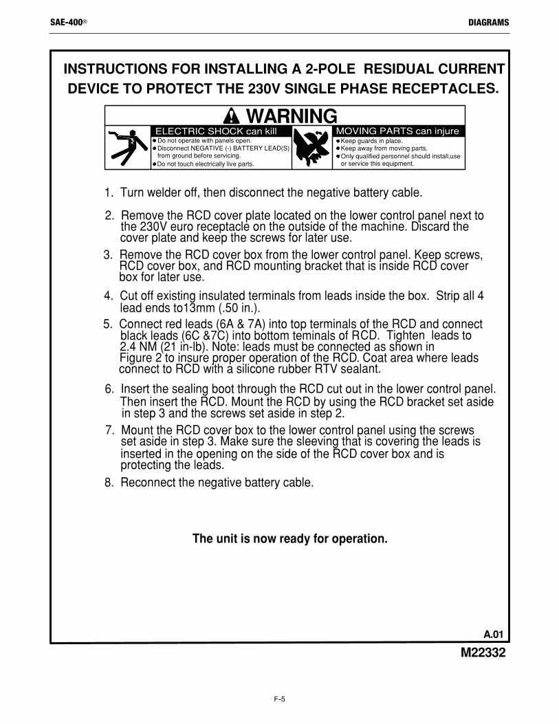
F-5
DIAGRAMSSAE-400®
WARNINGDo not operate with panels open.
Do not touch electrically live parts.
Keep guards in place.Keep away from moving parts.Only qualified personnel should install,useor service this equipment.
Disconnect NEGATIVE (-) BATTERY LEAD(S)from ground before servicing.
INSTRUCTIONS FOR INSTALLING A 2-POLE RESIDUAL CURRENT DEVICE TO PROTECT THE 230V SINGLE PHASE RECEPTACLES.
1. Turn welder off, then disconnect the negative battery cable.
3. Remove the RCD cover box from the lower control panel. Keep screws, RCD cover box, and RCD mounting bracket that is inside RCD cover box for later use.
ELECTRIC SHOCK can kill MOVING PARTS can injure
2. Remove the RCD cover plate located on the lower control panel next to the 230V euro receptacle on the outside of the machine. Discard the cover plate and keep the screws for later use.
6. Insert the sealing boot through the RCD cut out in the lower control panel. Then insert the RCD. Mount the RCD by using the RCD bracket set aside in step 3 and the screws set aside in step 2.7. Mount the RCD cover box to the lower control panel using the screws set aside in step 3. Make sure the sleeving that is covering the leads is inserted in the opening on the side of the RCD cover box and is protecting the leads.8. Reconnect the negative battery cable.
4. Cut off existing insulated terminals from leads inside the box. Strip all 4 lead ends to13mm (.50 in.).5. Connect red leads (6A & 7A) into top terminals of the RCD and connect black leads (6C &7C) into bottom teminals of RCD. Tighten leads to 2.4 NM (21 in-lb). Note: leads must be connected as shown in Figure 2 to insure proper operation of the RCD. Coat area where leads connect to RCD with a silicone rubber RTV sealant.
The unit is now ready for operation.
M22332
A.01
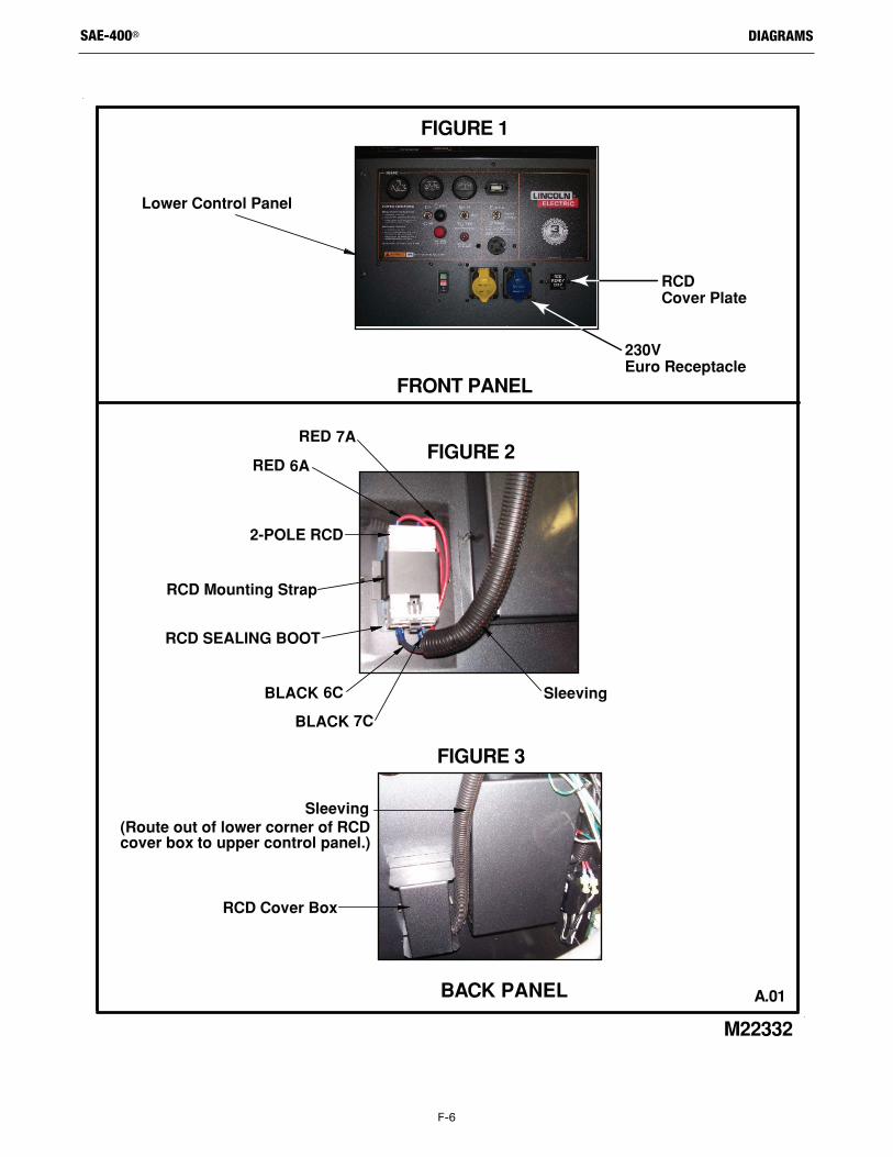
F-6
DIAGRAMSSAE-400®
A.01
M22332
BACK PANEL
FRONT PANEL
FIGURE 2
RCD SEALING BOOT
RCD Mounting Strap
2-POLE RCD
Sleeving
FIGURE 3
RCD Cover Box
Sleeving(Route out of lower corner of RCDcover box to upper control panel.)
RED 6A
RED 7A
BLACK 6C
BLACK 7C
FIGURE 1
RCD Cover Plate
Lower Control Panel
230V Euro Receptacle
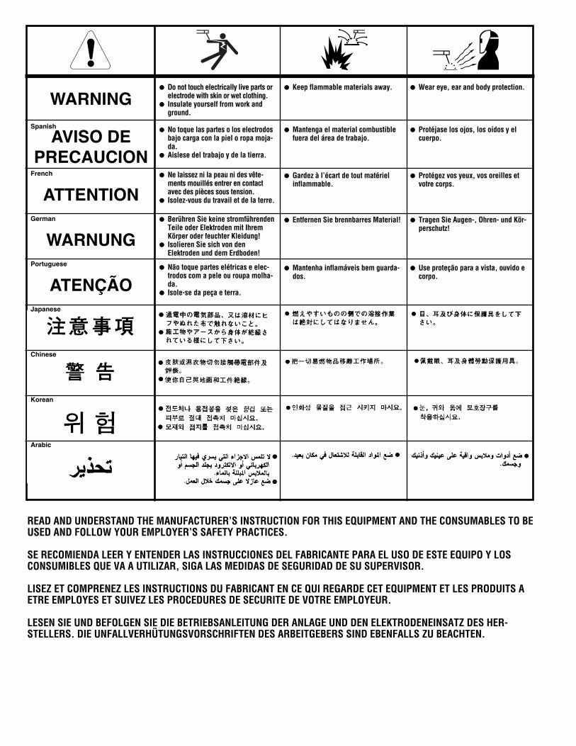
WARNING
AVISO DEPRECAUCION
ATTENTION
WARNUNG
ATENÇÃO
Spanish
French
German
Portuguese
Japanese
Chinese
Korean
Arabic
READ AND UNDERSTAND THE MANUFACTURER’S INSTRUCTION FOR THIS EQUIPMENT AND THE CONSUMABLES TO BEUSED AND FOLLOW YOUR EMPLOYER’S SAFETY PRACTICES.
SE RECOMIENDA LEER Y ENTENDER LAS INSTRUCCIONES DEL FABRICANTE PARA EL USO DE ESTE EQUIPO Y LOSCONSUMIBLES QUE VA A UTILIZAR, SIGA LAS MEDIDAS DE SEGURIDAD DE SU SUPERVISOR.
LISEZ ET COMPRENEZ LES INSTRUCTIONS DU FABRICANT EN CE QUI REGARDE CET EQUIPMENT ET LES PRODUITS AETRE EMPLOYES ET SUIVEZ LES PROCEDURES DE SECURITE DE VOTRE EMPLOYEUR.
LESEN SIE UND BEFOLGEN SIE DIE BETRIEBSANLEITUNG DER ANLAGE UND DEN ELEKTRODENEINSATZ DES HER-STELLERS. DIE UNFALLVERHÜTUNGSVORSCHRIFTEN DES ARBEITGEBERS SIND EBENFALLS ZU BEACHTEN.
l Do not touch electrically live parts orelectrode with skin or wet clothing.
l Insulate yourself from work andground.
l No toque las partes o los electrodosbajo carga con la piel o ropa moja-da.
l Aislese del trabajo y de la tierra.
l Ne laissez ni la peau ni des vête-ments mouillés entrer en contactavec des pièces sous tension.
l Isolez-vous du travail et de la terre.
l Berühren Sie keine stromführendenTeile oder Elektroden mit IhremKörper oder feuchter Kleidung!
l Isolieren Sie sich von denElektroden und dem Erdboden!
l Não toque partes elétricas e elec-trodos com a pele ou roupa molha-da.
l Isole-se da peça e terra.
l Keep flammable materials away.
l Mantenga el material combustiblefuera del área de trabajo.
l Gardez à l’écart de tout matérielinflammable.
l Entfernen Sie brennbarres Material!
l Mantenha inflamáveis bem guarda-dos.
l Wear eye, ear and body protection.
l Protéjase los ojos, los oídos y elcuerpo.
l Protégez vos yeux, vos oreilles etvotre corps.
l Tragen Sie Augen-, Ohren- und Kör-perschutz!
l Use proteção para a vista, ouvido ecorpo.
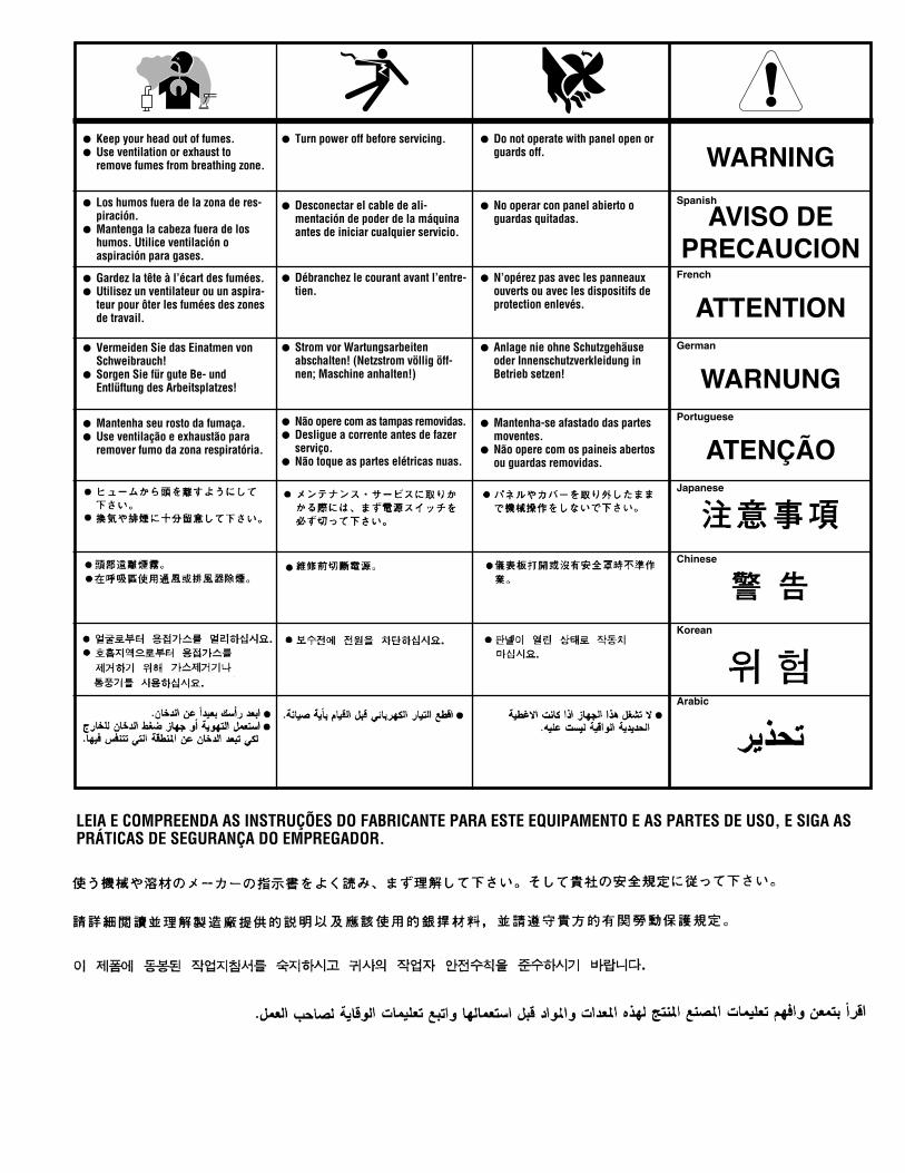
WARNING
AVISO DEPRECAUCION
ATTENTION
WARNUNG
ATENÇÃO
Spanish
French
German
Portuguese
Japanese
Chinese
Korean
Arabic
LEIA E COMPREENDA AS INSTRUÇÕES DO FABRICANTE PARA ESTE EQUIPAMENTO E AS PARTES DE USO, E SIGA ASPRÁTICAS DE SEGURANÇA DO EMPREGADOR.
l Keep your head out of fumes.l Use ventilation or exhaust to
remove fumes from breathing zone.
l Los humos fuera de la zona de res-piración.
l Mantenga la cabeza fuera de loshumos. Utilice ventilación oaspiración para gases.
l Gardez la tête à l’écart des fumées.l Utilisez un ventilateur ou un aspira-
teur pour ôter les fumées des zonesde travail.
l Vermeiden Sie das Einatmen vonSchweibrauch!
l Sorgen Sie für gute Be- undEntlüftung des Arbeitsplatzes!
l Mantenha seu rosto da fumaça.l Use ventilação e exhaustão para
remover fumo da zona respiratória.
l Turn power off before servicing.
l Desconectar el cable de ali-mentación de poder de la máquinaantes de iniciar cualquier servicio.
l Débranchez le courant avant l’entre-tien.
l Strom vor Wartungsarbeitenabschalten! (Netzstrom völlig öff-nen; Maschine anhalten!)
l Não opere com as tampas removidas.l Desligue a corrente antes de fazer
serviço.l Não toque as partes elétricas nuas.
l Do not operate with panel open orguards off.
l No operar con panel abierto oguardas quitadas.
l N’opérez pas avec les panneauxouverts ou avec les dispositifs deprotection enlevés.
l Anlage nie ohne Schutzgehäuseoder Innenschutzverkleidung inBetrieb setzen!
l Mantenha-se afastado das partesmoventes.
l Não opere com os paineis abertosou guardas removidas.

CUSTOMER ASSISTANCE POLICY
The business of The Lincoln Electric Company is manufacturingand selling high quality welding equipment, consumables, andcutting equipment. Our challenge is to meet the needs of ourcustomers and to exceed their expectations. On occasion,purchasers may ask Lincoln Electric for advice or informationabout their use of our products. We respond to our customersbased on the best information in our possession at that time.Lincoln Electric is not in a position to warrant or guarantee suchadvice, and assumes no liability, with respect to such informationor advice. We expressly disclaim any warranty of any kind,including any warranty of fitness for any customer’s particularpurpose, with respect to such information or advice. As a matterof practical consideration, we also cannot assume any respon-sibility for updating or correcting any such information or adviceonce it has been given, nor does the provision of information oradvice create, expand or alter any warranty with respect to thesale of our products.
Lincoln Electric is a responsive manufacturer, but the selectionand use of specific products sold by Lincoln Electric is solelywithin the control of, and remains the sole responsibility of thecustomer. Many variables beyond the control of Lincoln Electricaffect the results obtained in applying these types of fabricationmethods and service requirements.
Subject to Change – This information is accurate to the best of ourknowledge at the time of printing. Please refer to www.lincolnelectric.com for any updated information.