Embed Size (px)
Citation preview
1
Sabre Sailing Association of Australia
Rule Changes passed by Special General Meetings held 30
November 2013 and 15th Feb 2014 which took effect on 1st and
15th February 2014.
1. Single Fixed Datum Point for Basic Hull Measurement
2. Changes as a consequence of amended Rule 2.2 - Hull Datum Point and Transom Top
Datum Point.
3. Chain Plates measurement from Transom Top Data Point.
4. Mast step height above foredeck, maximum height of mast above foredeck.
5. Mast step material, mast step attachment. 6. Rule 6.1(g) Mast cut-outs.
7. Rule 7.2(b) Vang attachment point.
8. Rudder cheek thickness and construction.
9. Transom Stern Post width.
10. Transom Pintle spacers.
11. Outhaul system.
12. Redundant Clew Outhaul diagram.
13. Allow outhaul control lines inside the boom.
14. Tiller dimensions.
15. Ply panels joining method options.
16. Floor Battens – Timber construction Step 28
17. Change Mast Web and Webb Support definition for ply boat.
18. Remove references to proprietary products.
19. Remove references to construction materials not readily available.
20. Remove references to epoxy glue.
21. Scuppers / Transom flaps.
22. Main halyard cleating position.
23. Gunwale radius.
24. Option of Plastic Cable ties or Copper Wire in construction of timber boats
25. Timber dimension and types general note.
26. Hull Identification with the Sail Number.
27. Obsolete information in Section D – Fitting Out.
28. Remove obsolete Boom Vang layout.
29. Remove Painting and Maintenance instructions.
30. FRP Centreboard only constructed by ‘authorised builders’.
31. Centreboard and Rudder measurement clarification to meet ISAF standards.
32. Remove references to the use of silicon sealant.
33. Optional position for Mainsheet Ratchet Block and attachment method.
34. Boom section.
35. Method for attaching shrouds to mast tangs and halyard material – Diag. #25A.
36. Mast vang attachment point incorrectly specified in Diag. #25B.
37. Mast ‘cut out’ for sail luff.
38. Remove references to Imperial measurements.
39. Enhance safety warnings.
40. Change FRP mould measurement procedure.
2
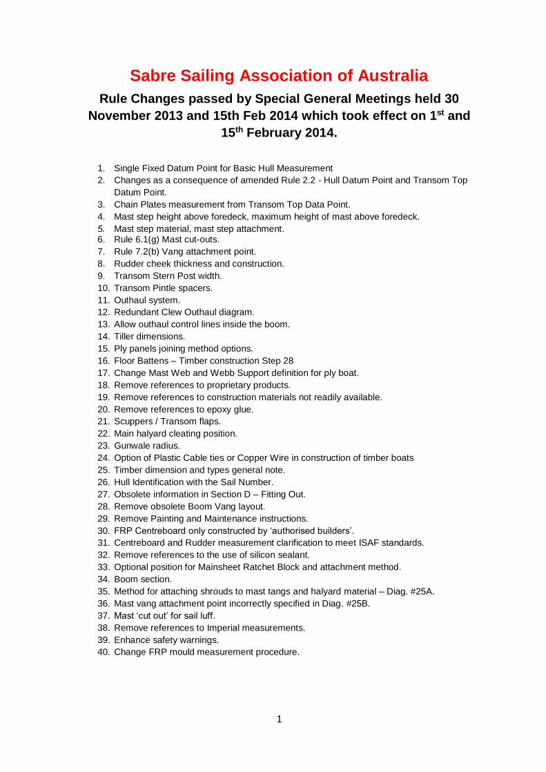
1. Single Fixed Datum Plane for Basic Hull Measurement
Good boat measurement practice bases all measurement on a fixed datum point. This is
recognized in the ISAF guidelines.
Sabre hull measurement is largely based on a fixed datum point at the transom but
previously diverged from this around the centrecase bulkhead measurement. Mast step
position, Rocker and two of the three chine to chine measurements are based on a fixed
distance from the transom datum point.
The third chine to chine measurement and two of the gunwale to gunwale measurements
were based on the position of the centrecase bulkhead which can vary by 39mm fore and
aft. The consequence of this is that the width of the boat is variable according to the
location of the centrecase bulkhead. This variation adds another 20mm to the tolerances
at the web bulkhead and approximately 10mm at the centrecase bulkhead.
By inference in the construction notes the position of the shroud plates is controlled by the
location of the centrecase bulkhead whereas the mast position is controlled from the
transom datum point.
Having a fixed datum point gives certainty to hull builders, those fitting out boats and to measurers.
Existing dimensions have been retained wherever possible and the new dimensions have
been derived from existing measurement rules to be as close as possible to the original
intent. This more accurately controls the width dimensions of the hull and also controls
the offset of the shroud plates from the mast. The revised hull measurements bring the
Sabre rules close to ISAF hull measurement guidelines.
3
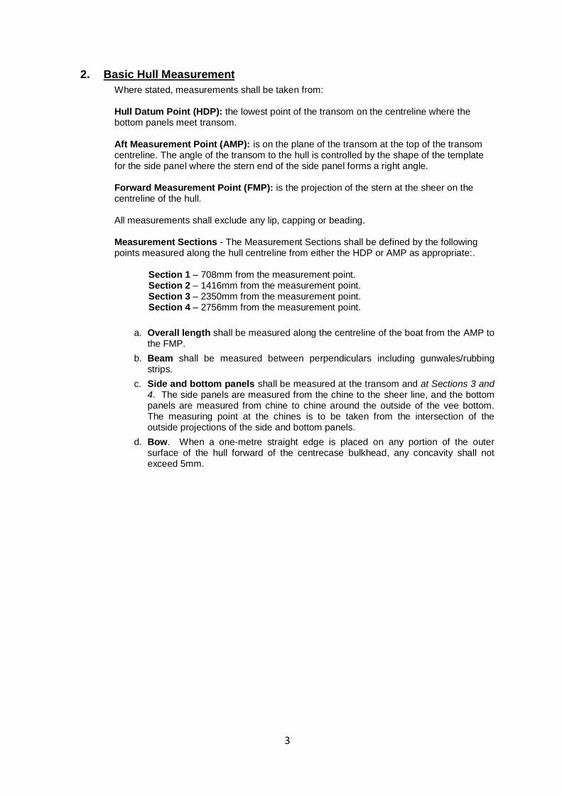
2. Basic Hull Measurement
Where stated, measurements shall be taken from: Hull Datum Point (HDP): the lowest point of the transom on the centreline where the bottom panels meet transom.
Aft Measurement Point (AMP): is on the plane of the transom at the top of the transom centreline. The angle of the transom to the hull is controlled by the shape of the template for the side panel where the stern end of the side panel forms a right angle. Forward Measurement Point (FMP): is the projection of the stern at the sheer on the centreline of the hull. All measurements shall exclude any lip, capping or beading. Measurement Sections - The Measurement Sections shall be defined by the following points measured along the hull centreline from either the HDP or AMP as appropriate:.
Section 1 – 708mm from the measurement point. Section 2 – 1416mm from the measurement point. Section 3 – 2350mm from the measurement point. Section 4 – 2756mm from the measurement point.
a. Overall length shall be measured along the centreline of the boat from the AMP to the FMP.
b. Beam shall be measured between perpendiculars including gunwales/rubbing strips.
c. Side and bottom panels shall be measured at the transom and at Sections 3 and 4. The side panels are measured from the chine to the sheer line, and the bottom panels are measured from chine to chine around the outside of the vee bottom. The measuring point at the chines is to be taken from the intersection of the outside projections of the side and bottom panels.
d. Bow. When a one-metre straight edge is placed on any portion of the outer surface of the hull forward of the centrecase bulkhead, any concavity shall not exceed 5mm.
4
HULL DATUM POINT
AFT MEASUREMENT POINT
HULL DATUM POINT
5
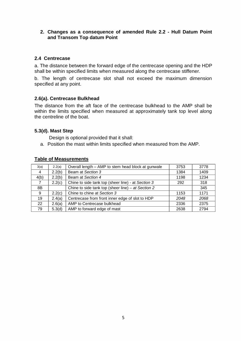
2. Changes as a consequence of amended Rule 2.2 - Hull Datum Point and Transom Top datum Point
2.4 Centrecase
a. The distance between the forward edge of the centrecase opening and the HDP shall be within specified limits when measured along the centrecase stiffener.
b. The length of centrecase slot shall not exceed the maximum dimension specified at any point.
2.6(a). Centrecase Bulkhead
The distance from the aft face of the centrecase bulkhead to the AMP shall be within the limits specified when measured at approximately tank top level along the centreline of the boat.
5.3(d). Mast Step
Design is optional provided that it shall:
a. Position the mast within limits specified when measured from the AMP.
Table of Measurements
3(a) 2.2(a) Overall length – AMP to stem head block at gunwale 3753 3778
4 2.2(b) Beam at Section 3 1384 1409
4(b) 2.2(b) Beam at Section 4 1198 1234
7 2.2(c) Chine to side tank top (sheer line) - at Section 3 292 318
8B Chine to side tank top (sheer line) – at Section 2 345
9 2.2(c) Chine to chine at Section 3 1153 1171
19 2.4(a) Centrecase from front inner edge of slot to HDP 2048 2068
22 2.6(a) AMP to Centrecase bulkhead 2336 2375
79 5.3(d) AMP to forward edge of mast 2638 2794
6
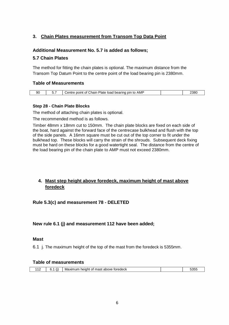
3. Chain Plates measurement from Transom Top Data Point
Additional Measurement No. 5.7 is added as follows;
5.7 Chain Plates
The method for fitting the chain plates is optional. The maximum distance from the
Transom Top Datum Point to the centre point of the load bearing pin is 2380mm.
Table of Measurements
90 5.7 Centre point of Chain Plate load bearing pin to AMP 2380
Step 28 - Chain Plate Blocks
The method of attaching chain plates is optional.
The recommended method is as follows.
Timber 48mm x 18mm cut to 150mm. The chain plate blocks are fixed on each side of the boat, hard against the forward face of the centrecase bulkhead and flush with the top of the side panels. A 16mm square must be cut out of the top corner to fit under the bulkhead top. These blocks will carry the strain of the shrouds. Subsequent deck fixing must be hard on these blocks for a good watertight seal. The distance from the centre of the load bearing pin of the chain plate to AMP must not exceed 2380mm.
4. Mast step height above foredeck, maximum height of mast above
foredeck
Rule 5.3(c) and measurement 78 - DELETED
New rule 6.1 (j) and measurement 112 have been added;
Mast
6.1 j. The maximum height of the top of the mast from the foredeck is 5355mm.
Table of measurements
112 6.1 (j) Maximum height of mast above foredeck 5355
7
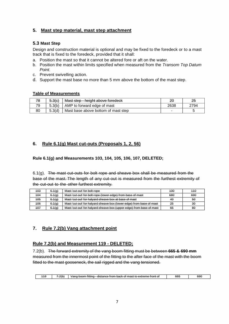
5. Mast step material, mast step attachment
5.3 Mast Step
Design and construction material is optional and may be fixed to the foredeck or to a mast track that is fixed to the foredeck, provided that it shall:
a. Position the mast so that it cannot be altered fore or aft on the water. b. Position the mast within limits specified when measured from the Transom Top Datum
Point. c. Prevent swivelling action.
d. Support the mast base no more than 5 mm above the bottom of the mast step.
Table of Measurements
78 5.3(c) Mast step - height above foredeck 20 25
79 5.3(b) AMP to forward edge of mast 2638 2794
80 5.3(d) Mast base above bottom of mast step - 5
6. Rule 6.1(g) Mast cut-outs (Proposals 1, 2, 56)
Rule 6.1(g) and Measurements 103, 104, 105, 106, 107, DELETED;
6.1(g). The mast cut-outs for bolt rope and sheave box shall be measured from the
base of the mast. The length of any cut-out is measured from the furthest extremity of
the cut-out to the other furthest extremity.
103 6.1(g) Mast 'cut out' for bolt rope 100 110
104 6.1(g) Mast 'cut out' for bolt rope (lower edge) from base of mast 680 690
105 6.1(g) Mast 'cut out' for halyard sheave box at base of mast 40 50
106 6.1(g) Mast 'cut out' for halyard sheave box (lower edge) from base of mast 25 30
107 6.1(g) Mast 'cut out' for halyard sheave box (upper edge) from base of mast 65 80
7. Rule 7.2(b) Vang attachment point
Rule 7.2(b) and Measurement 119 - DELETED;
7.2(b). The forward extremity of the vang boom fitting must be between 665 & 690 mm
measured from the innermost point of the fitting to the after face of the mast with the boom
fitted to the mast gooseneck, the sail rigged and the vang tensioned.
119 7.2(b) Vang boom fitting - distance from back of mast to extreme front of fitting
665 690
8
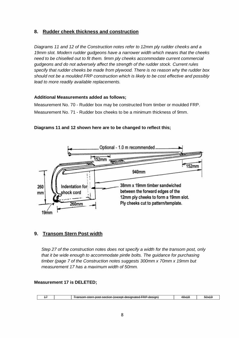
8. Rudder cheek thickness and construction
Diagrams 11 and 12 of the Construction notes refer to 12mm ply rudder cheeks and a
19mm slot. Modern rudder gudgeons have a narrower width which means that the cheeks
need to be chiselled out to fit them. 9mm ply cheeks accommodate current commercial
gudgeons and do not adversely affect the strength of the rudder stock. Current rules
specify that rudder cheeks be made from plywood. There is no reason why the rudder box
should not be a moulded FRP construction which is likely to be cost effective and possibly
lead to more readily available replacements.
Additional Measurements added as follows;
Measurement No. 70 - Rudder box may be constructed from timber or moulded FRP.
Measurement No. 71 - Rudder box cheeks to be a minimum thickness of 9mm.
Diagrams 11 and 12 shown here are to be changed to reflect this;
9. Transom Stern Post width
Step 27 of the construction notes does not specify a width for the transom post, only
that it be wide enough to accommodate pintle bolts. The guidance for purchasing
timber (page 7 of the Construction notes suggests 300mm x 70mm x 19mm but
measurement 17 has a maximum width of 50mm.
Measurement 17 is DELETED;
17 Transom stern post section (except designated FRP design) 48x18 50x19
9
The suggested timber width of the transom post on page 7 is amended as follows;
30mm x 19mm and wide enough to accommodate the the bolt centres of the rudder
pintles.
10. Transom Pintle spacers
New measurement No. 90 is added as follows;
Optional Transom pintles spacers with a maximum thickness of 15mm may be
attached to the transom.
11. Outhaul system
The towel rail system is an expensive outhaul control method in comparison to modern
and simple rope/webbing systems. The option is now available to use any system as long
as the sail cannot be let in less than 1830 mm from the aft side of the mast.
7.2 a. An outhaul for on-water adjustment of the clew of the sail is optional.
The traditional method is shown on Diag. #26 - Boom Layout & Detail of Outhaul Towel Rail in the Construction & Fitting Out Notes.
Rope and / or webbing systems may optionally be used as long as the clew of the sail cannot be let in less than 1830mm to the after face of the mast when the boom is fixed onto the mast gooseneck.
If a towel rail is used, its location is measured from the innermost edge of the traveller to the after face of the mast when the boom is fixed onto the mast gooseneck and its location must conform to measurement 118. The length of the towel rail is optional.
Slots in the boom for an internal track system are not allowed.
118 7.2(a) Inner Outhaul position, refer Diag. #26 1830 1842
118(a) Deleted
The following sentence is deleted from Section D – Fitting Out on page 41;
▪ A ‘towel rail’ is the only permitted means of providing on-water adjustment of the clew outhaul position.
12. Redundant Clew Outhaul diagram #27
The location of blocks, saddles and clew attachment methods to the clew of the sail vary
widely, none of which are deemed performance enhancing.
Diagram #27 is obsolete and is redundant now the option of rope/webbing outhaul
systems is allowed - deleted.

10
13. Allow outhaul control lines inside the boom.
The boom is not sealed so there is no need for this rule to stop water entry. Allowing an
internal control removes the possibility of the outhaul control line fouling on clothing or
other items of the boat.
Rule 7.1 (c) as shown below is DELETED;
Rule 7.1 (c) - Control lines or halyards are not allowed within the boom section.
11
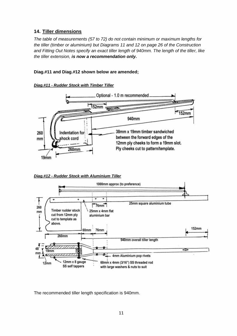
14. Tiller dimensions
The table of measurements (57 to 72) do not contain minimum or maximum lengths for
the tiller (timber or aluminium) but Diagrams 11 and 12 on page 26 of the Construction
and Fitting Out Notes specify an exact tiller length of 940mm. The length of the tiller, like
the tiller extension, is now a recommendation only.
Diag.#11 and Diag.#12 shown below are amended;
Diag.#11 - Rudder Stock with Timber Tiller
Diag.#12 - Rudder Stock with Aluminium Tiller
The recommended tiller length specification is 940mm.
12
15. Ply panels joining method options
Step 2 of the Construction and Fitting Out Notes only refers to the Butt Strap method of
joining ply panels. Scarf joints are more difficult but the accomplished amateur builder
should not be prevented from its use.
Step 2 of the Construction Notes is amended to;
Step 2 - Joining Bottom Panels 1 & 1A & Side Panels 2 & 2A (Diags. #2A, 2B & 2C)
THIS IS A VITAL STEP
Cut the 60mm wide 5mm ply butt straps to length 50mm short of where the bottom panels butt together. Scarfing or finger jointing of the ply panels is permissible. Similarly cut the butt straps to length for the side panel joins, but run these straps to the edge that will later be the top gunwale edge of the side panels.
The gaps between the end of the butt straps and the edges of the ply are to allow for fibreglass tape to be run along the keel and chine ply joints after the boat is wired up. Refer to Diags. #2A & 2B to be sure the ply panels to be joined are laid the correct way. Glue each butt strap, with the strap exactly over the centre of the meeting of the ply panels, on the INSIDE face of the ply, i.e. facing up into the boat.
Temporarily nail the strap on with 4 nails (to be removed later), turn the whole unit over and at 50mm centres on each side of the join in a zigzag pattern, fix with 19mm copper flathead nails, punch slightly, turn over again, bend the protruding nails flat onto the strap giving a strong join to the two panels. Care must be taken that the edges joined are hard up together and that the outside edges form a continuous line. Ample glue must be used.
Induce a 25mm bend as shown in the Diag. #2C before the glue sets to avoid “hard” spots, otherwise the proper bottom shape will be very difficult to induce after the glue has set.
Complete the four joins making up the two bottom panels 1 and 1A, and the two side panels 2 and 2A. Wipe off excess glue and leave 24 hours for glue to cure.
NOTE: At the top of the gunwale edges of the side panels, panels 2 and 2A, the butt strap goes to the edge of the ply or over if you wish. See Diag. #2B.
Alternative Butt Strap Method
Use 8mm screws in lieu of copper nails; countersink and screw from inside the hull, then later file off protruding screw threads before fibreglassing the exterior of the butt joint.
If you are fibreglassing the exterior of the bottom panels to bring them up to thickness, the taping of the butt joints can be done at that time.
16. Floor Battens – Timber construction Step 29
The minimum number of battens in a timber boat is 4 with a maximum of 6. The
mandatory battens previously had to pass through the centrecase bulkhead to a
maximum 25mm. While it will add weight, battens are now allowed to extend from the
transom to the bow for extra stiffness. The existing number of battens, dimensions and
positioning are now recommendations rather than mandatory
Step 29 - Floor Battens Two timber battens, minimum 36mm x 18mm (recommended 40mm x 19mm), are to be fixed to the floor on each side of the keel inside the cockpit. The minimum length of the inner batten is 2260mm (recommended max 2280mm) and the outer batten minimum
13
length is 1990mm (recommended max 2010mm) (Meas. #27). These shall be located 125mm and 250mm from centreline of keel to the centre of the respective batten, and both must be inserted through pre-cut holes in the main bulkhead (recommended 25mm through the centrecase bulkhead). Allow for this when cutting the floor battens to length. Each batten may have a maximum of 5 limber holes (max 5mm radius) along its length. An additional batten may be fitted on each side between the outer batten and the side tank.
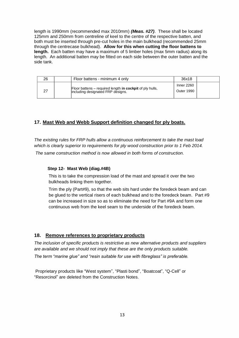
26 Floor battens - minimum 4 only 36x18
27 Floor battens – required length in cockpit of ply hulls, including designated FRP designs.
Inner 2260
Outer 1990
17. Mast Web and Webb Support definition changed for ply boats.
The existing rules for FRP hulls allow a continuous reinforcement to take the mast load
which is clearly superior to requirements for ply wood construction prior to 1 Feb 2014.
The same construction method is now allowed in both forms of construction.
Step 12- Mast Web (diag.#4B)
This is to take the compression load of the mast and spread it over the two
bulkheads linking them together.
Trim the ply (Part#9), so that the web sits hard under the foredeck beam and can
be glued to the vertical risers of each bulkhead and to the foredeck beam. Part #9
can be increased in size so as to eliminate the need for Part #9A and form one
continuous web from the keel seam to the underside of the foredeck beam.
18. Remove references to proprietary products
The inclusion of specific products is restrictive as new alternative products and suppliers
are available and we should not imply that these are the only products suitable.
The term “marine glue” and “resin suitable for use with fibreglass” is preferable.
Proprietary products like “West system”, “Plasti bond”, “Boatcoat”, “Q-Cell” or
“Resorcinol” are deleted from the Construction Notes.
14
19. Remove references to construction materials not readily available
Brass pins are not readily available today.
References to “Glue and brass pin” under BUILDING INSTRUCTIONS Page 10 in the
Construction Notes are replaced;
with “clamp and glue”.
20. Remove references to epoxy glue
There are many other types of glue suitable for use in most applications e.g.
polyurethane.
All references in the Construction Notes to “epoxy glue” are replaced by “Glue”.
21. Scuppers / Transom flaps
Rule 1.11.2 i is DELETED;
1.11.2 Prohibitions
Without affecting the generality of Clause 1.10 – Options, Alterations & Repairs above, the following are prohibited:
i. Transom flaps.
ii.
Rule 1.11.3
1.11.3 Options
Without affecting the generality of Clause 1.10 – Options, Alterations & Repairs above, the following options are permissible:
Amended by adding;
t. Scuppers and Transom flaps (maximum of one each side of the stern post).
15
22. Main halyard cleating position (proposals 33 and 50)
There is no clear reason for these measurements and there should be an option to cleat a
rope halyard to a cleat attached to the top of the centrecase bulkhead.
Measurements 86 and 87 - DELETED;
86 Main halyard cleated aft of 102mm forward of centrecase bulkhead 102
87 Downhaul cleated aft of 102mm forward of centrecase bulkhead 102 .
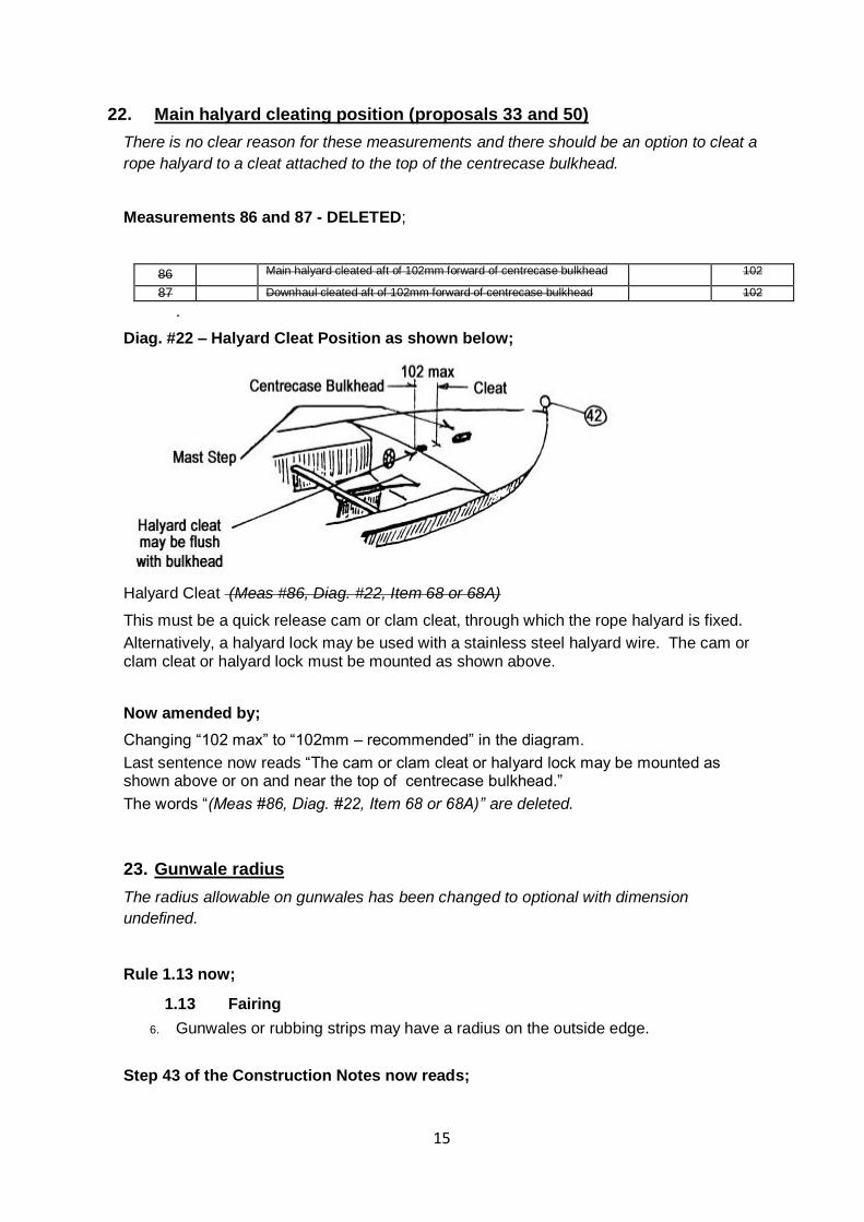
Diag. #22 – Halyard Cleat Position as shown below;
Halyard Cleat (Meas #86, Diag. #22, Item 68 or 68A)
This must be a quick release cam or clam cleat, through which the rope halyard is fixed.
Alternatively, a halyard lock may be used with a stainless steel halyard wire. The cam or clam cleat or halyard lock must be mounted as shown above.
Now amended by;
Changing “102 max” to “102mm – recommended” in the diagram.
Last sentence now reads “The cam or clam cleat or halyard lock may be mounted as shown above or on and near the top of centrecase bulkhead.”
The words “(Meas #86, Diag. #22, Item 68 or 68A)” are deleted.
23. Gunwale radius
The radius allowable on gunwales has been changed to optional with dimension
undefined.
Rule 1.13 now;
1.13 Fairing
6. Gunwales or rubbing strips may have a radius on the outside edge.
Step 43 of the Construction Notes now reads;
16
Trim deck ply flush with face of gunwales, glue the 4.3m x 25mm x 6mm capping strip. Ensure capping strip stands slightly higher than deck ply. When dry, sand down flush with deck. A radius is permitted on outside edges (Rule 1.13 – Fairing). At bow, finish off capping strips as per Diag. #9B.
24. Option of Plastic Cable ties or Copper Wire in construction of timber
boats
The cheaper option of using plastic cables is now allowed for holding the hull together
prior to glassing seams of a plywood boat.
Section A “FIXINGS List” (Guide only) is amended to;
12.2m of 1.22mm (18 SWG) …….Copper wire or plastic cable ties
And Step 7 – Wiring Up the Hull (Diag. #24) now reads;
References to “copper wire”, “wires”, “wiring”, “wired” in this step may also mean the optional use of plastic cable ties.
Cut the 12m length of copper wire into 60mm lengths. The two bottom panels (Parts #1 & 1A), now firmly butt joined together, are wired up together along the edges that have the cut-out section for the centreboard slot.
25. Timber dimension and types general note
Section A – Plywood Construction contains comment on timber sizes which are now
recommendations only with the objective of achieving a long lasting, light and stiff hull.
Section A – Plywood Sabre Construction on page 7 as shown below;
Timber Sizes Timber parts dimensions and timber types (except where a specific rule applies) are
recommended only to achieve a light and stiff and long lasting boat.
17
26. Hull Identification with the Sail Number
The requirement that the sail number be burnt or embossed into the aft keel of timber
boats is now removed. FRP and timber hull identification are now aligned.
Rule 1.7.6 – measurement 89 is amended to;
1.7.6 Each hull shall be marked permanently on the hull inside the Centre Bulkhead or on the rear face of the web bulkhead with the sail number issued for that hull, in letters not less than 40mm high and be visible looking through one of the Centre Bulkhead hatches.
1.7.6.1 – Deleted
1.7.6.2 – Deleted
89
1.7.6
Hull identification:
Permanently marked on hull inside the centre bulkhead or on rear face of the web bulkhead and visible through centre bulkhead hatch.
40
27. Obsolete information in Section D – Fitting Out removed
A number of articles for guidance are obsolete and because they are included in the
Construction, Rules and Fit Out Guide, theoretically must be used. There have even
been complaints from amateur builders that fittings cannot be sourced. Most of Section
D relates to 1970’s thinking and fittings and is removed to avoid confusion. More modern
fit out guidance is available (e.g. PDF produced by Chris Dance that is on the website).
The introduction to the Construction and Fitting Out Notes contains the following:
WARNING: No variations outside the Construction & Fitting Out Notes or the Measurement Rules are permitted unless approved in writing by the Sabre Sailing Association of Australia Inc. Only items specified in or permitted by the Measurement Rules or these building notes may be included in construction or fitting out of a Sabre.
Section E – Rules of Measurement and Construction
1.4 Construction & Fitting Out Notes
The Construction & Fitting Out Notes, as supplied by the Association for the construction of Sabre class dinghies, shall be read in conjunction with, and form part of these Rules.
Section D is amended as follows;
• Page 42 - Fit out guide schematic - Deleted.
• Pages 43-44 - Fittings purchase list - Deleted.
• Page 45 – “Cordage Summary” changed to “Cordage Guide”, and section “Fixings
List” Deleted.
• Pages 47-48 – “Theory of Slack Rope Hawse” section - Deleted.
• Pages 55-56 – Rigging and Tuning article - Deleted.
18
28. Obsolete Boom Vang layout - removed
The fittings and method of use are no longer current or relevant.
More modern fit out guidance is available (e.g. PDF produced by Chris Dance that is on
the website).
Diag. #30 Boom Vang Layout and renumber Diagrams - Removed.
29. Painting and Maintenance instructions removed
Section “A” – Plywood Sabre Construction, pages 31-32 contains instructions on painting
and maintenance. These processes are best left to the choice of the builder and depend
mainly upon the availability and suitability of current products.
Building and Construction Notes P31 and P32 are amended as follows;
Pages 31 and page 32 which specify painting and maintenance instructions -
Removed.
30. FRP Centreboard
Rule 3.1 is Amended as follows;
3.1 a. The centreboard shall be constructed to the profile illustrated in Diagram #13 in the Construction & Fitting Out Notes, of plywood, solid or laminated timber, and may be finished with a skin of fibreglass, such skin being included in the thickness dimension, or may be constructed of FRP material.
The following sentence in Step 49 is DELETED
These may only be constructed by builders authorised by the SSAA.
31. Centreboard and Rudder measurement clarification to meet ISAF
standards
Previously there was constant difficulty with the interpretation of the fairing rule,
specifically the reference to constant thickness. There was no provision for tolerance and
was almost impossible to comply with. Interpretation differed from State to State and the
builders complained regularly about the cost to them of replacing rejected foils. The new
rule is based on the Mirror class rules which meet ISAF standards. They reflect a
workable engineering tolerance.
19
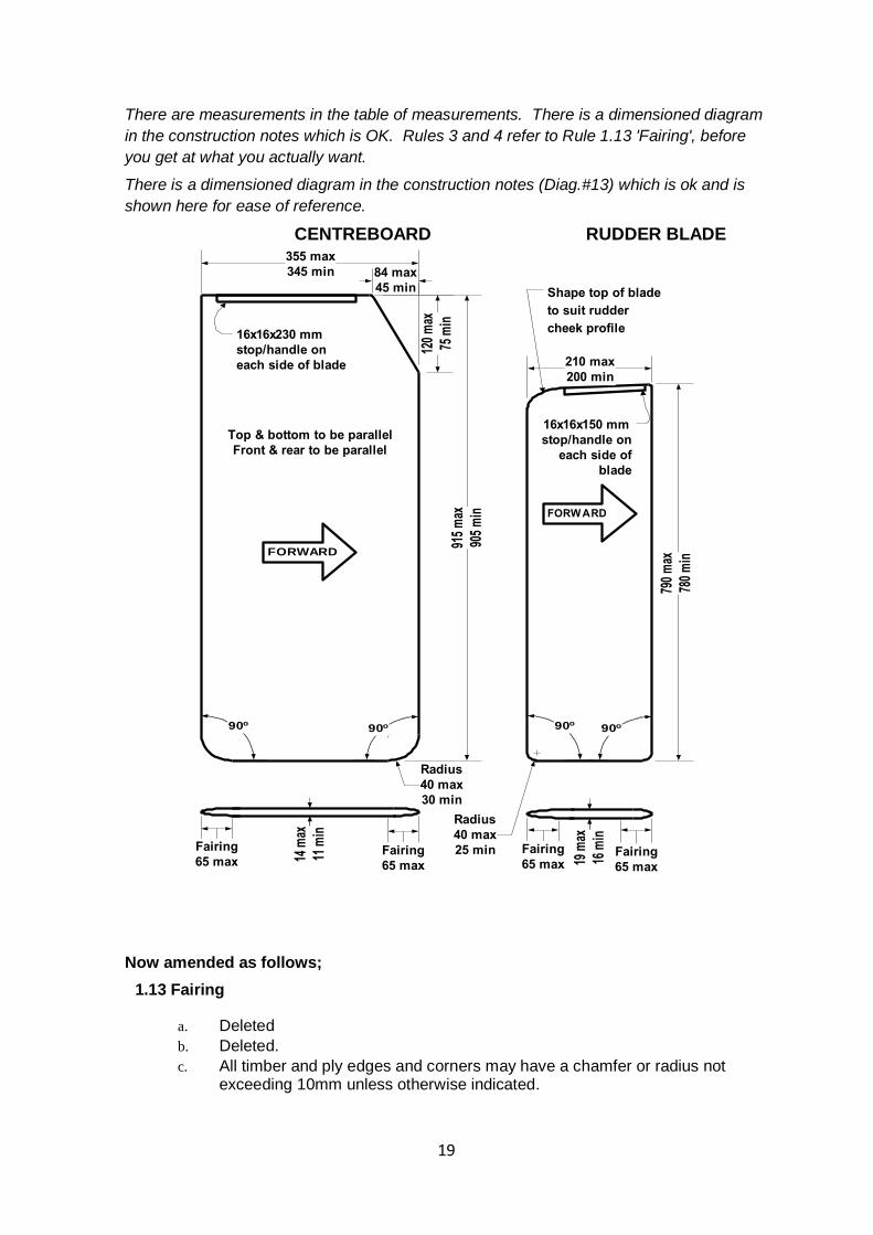
There are measurements in the table of measurements. There is a dimensioned diagram
in the construction notes which is OK. Rules 3 and 4 refer to Rule 1.13 'Fairing', before
you get at what you actually want.
There is a dimensioned diagram in the construction notes (Diag.#13) which is ok and is
shown here for ease of reference.
CENTREBOARD RUDDER BLADE
84 max
45 min
120
max
75 m
in91
5 m
ax
905
min
355 max
345 min
790
max
780
min
Radius
40 max
30 min
Radius
40 max
25 min
210 max
200 min
Fairing
65 maxFairing
65 max
14 m
ax
11 m
in
19 m
ax
16 m
in
Fairing
65 maxFairing
65 max
FORWARD
FORW ARD
Top & bottom to be parallel
Front & rear to be parallel
Shape top of blade
to suit rudder
cheek profile16x16x230 mm
stop/handle on
each side of blade
16x16x150 mm
stop/handle on
each side of
blade
90o90o 90o
90o
Now amended as follows;
1.13 Fairing
a. Deleted
b. Deleted.
c. All timber and ply edges and corners may have a chamfer or radius not exceeding 10mm unless otherwise indicated.
20
d. Transom post, floor battens and keel may be rounded to a segment of circle the width and height being not more than the thickness of the timber called for in the Construction & Fitting Out Notes and/or these Rules.
e. Gunwales or rubbing strips may have a radius on the outside edge.
3. CENTREBOARD Refer to Diagram #13 in the Construction & Fitting Out Notes.
a. The Centreboard shall be constructed of, plywood, solid or laminated timber
and may be finished with a skin of fibreglass. The Centreboard may also be
constructed using FRP to the specification described in Part 1 Section B item
8 of the construction notes.
b. The Centreboard shall conform to diagram #13 of the Construction Notes. The Centreboard shall be between 11mm and 14mm thick and the thickness shall not vary by more than 1mm to within 65mm of its edges with the exception of hollows or cavities of not more than 2mm in dimension. A tolerance of 1mm is permitted in the flat section between the 65mm wide faired edges. The leading, trailing and bottom edges of the Centreboard shall be within 5mm of a straight line and the leading and trailing edges shall be parallel within a tolerance of 5mm.
4. RUDDER ASSEMBLY Refer to Diagram #13 in the Construction & Fitting Out Notes.
a. The Rudder Blade shall be of the sliding type and shall be constructed of,
plywood, solid or laminated timber and may be finished with a skin of
fibreglass. The Rudder Blade may also be constructed using FRP to the
specification described in Part 1 Section B item 8 of the construction notes.
b. The Rudder Blade shall conform to diagram #13 of the Construction Notes. The Rudder Blade shall be between 16mm and 19mm thick and the thickness shall not vary by more than 1mm to within 65mm of its edges with the exception of hollows or cavities of not more than 2mm in dimension. A tolerance of 1mm is permitted in the flat section between the 65mm wide faired edges. The leading, trailing and bottom edges of the Rudder Blade shall be within 5mm of a straight line and the leading and trailing edges shall be parallel within a tolerance of 5mm.
c. In accordance with Yachting Australia Special Regulations, Part 2
Regulation 6 a stainless steel pin shall be fitted through a pintle to prevent
the rudder becoming detached.
21
32. Remove references to the use of silicon sealant
There are many specific products that prevent electrolysis available and silicon sealant
performs very poorly in this use.
References to the use of silicon sealant to mast and boom fitting as
electrolysis prevention measure are DELETED.
33. Optional position for Mainsheet Ratchet Block and attachment method
Ratchet blocks are optional in the mainsheet system. It was traditional in the 1970’s to
attach a ratchet block as per Diag #20 but there is no reason why a ratchet block cannot
be attached to the boom, or for that matter have one mounted off the keel and another on
the boom. Diag #20 does not reflect the modern practice of attaching the last block off the
floor by rope strop. Many sailors no longer adjust the rope hawse while sailing and just tie
it off, so the requirement for a clam cleat is now formally an option.
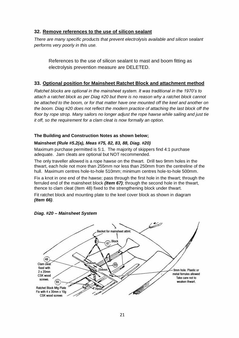
The Building and Construction Notes as shown below;
Mainsheet (Rule #5.2(a), Meas #75, 82, 83, 88, Diag. #20)
Maximum purchase permitted is 5:1. The majority of skippers find 4:1 purchase adequate. Jam cleats are optional but NOT recommended.
The only traveller allowed is a rope hawse on the thwart. Drill two 9mm holes in the thwart, each hole not more than 255mm nor less than 250mm from the centreline of the hull. Maximum centres hole-to-hole 510mm; minimum centres hole-to-hole 500mm.
Fix a knot in one end of the hawse; pass through the first hole in the thwart; through the ferruled end of the mainsheet block (Item 67); through the second hole in the thwart, thence to clam cleat (Item 48) fixed to the strengthening block under thwart.
Fit ratchet block and mounting plate to the keel cover block as shown in diagram (Item 66).
Diag. #20 – Mainsheet System
22
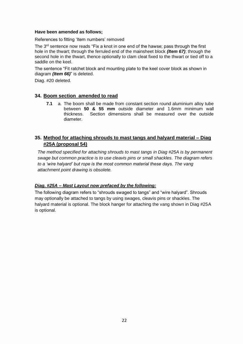
Have been amended as follows;
References to fitting ‘Item numbers’ removed
The 3rd sentence now reads “Fix a knot in one end of the hawse; pass through the first hole in the thwart; through the ferruled end of the mainsheet block (Item 67); through the second hole in the thwart, thence optionally to clam cleat fixed to the thwart or tied off to a saddle on the keel.
The sentence “Fit ratchet block and mounting plate to the keel cover block as shown in diagram (Item 66)” is deleted.
Diag. #20 deleted.
34. Boom section amended to read
7.1 a. The boom shall be made from constant section round aluminium alloy tube between 50 & 55 mm outside diameter and 1.6mm minimum wall thickness. Section dimensions shall be measured over the outside diameter.
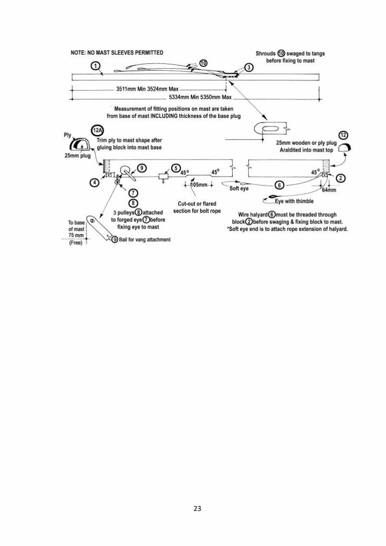
35. Method for attaching shrouds to mast tangs and halyard material – Diag
#25A (proposal 54)
The method specified for attaching shrouds to mast tangs in Diag #25A is by permanent
swage but common practice is to use cleavis pins or small shackles. The diagram refers
to a ‘wire halyard’ but rope is the most common material these days. The vang
attachment point drawing is obsolete.
Diag. #25A – Mast Layout now prefaced by the following:
The following diagram refers to “shrouds swaged to tangs” and “wire halyard”. Shrouds
may optionally be attached to tangs by using swages, cleavis pins or shackles. The
halyard material is optional. The block hanger for attaching the vang shown in Diag #25A
is optional.
23
24
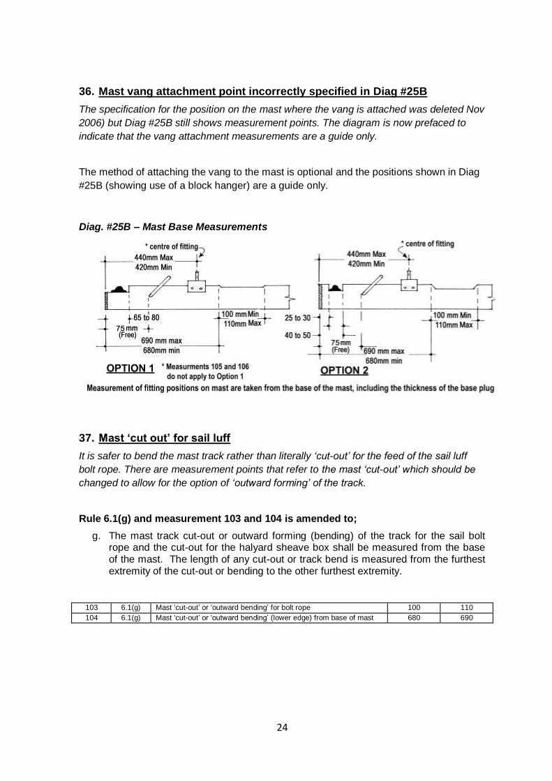
36. Mast vang attachment point incorrectly specified in Diag #25B
The specification for the position on the mast where the vang is attached was deleted Nov
2006) but Diag #25B still shows measurement points. The diagram is now prefaced to
indicate that the vang attachment measurements are a guide only.
The method of attaching the vang to the mast is optional and the positions shown in Diag
#25B (showing use of a block hanger) are a guide only.
Diag. #25B – Mast Base Measurements
37. Mast ‘cut out’ for sail luff
It is safer to bend the mast track rather than literally ‘cut-out’ for the feed of the sail luff
bolt rope. There are measurement points that refer to the mast ‘cut-out’ which should be
changed to allow for the option of ‘outward forming’ of the track.
Rule 6.1(g) and measurement 103 and 104 is amended to;
g. The mast track cut-out or outward forming (bending) of the track for the sail bolt rope and the cut-out for the halyard sheave box shall be measured from the base of the mast. The length of any cut-out or track bend is measured from the furthest extremity of the cut-out or bending to the other furthest extremity.
103 6.1(g) Mast ‘cut-out’ or ‘outward bending’ for bolt rope 100 110
104 6.1(g) Mast ‘cut-out’ or ‘outward bending’ (lower edge) from base of mast 680 690
25
38. Remove references to Imperial measurements
There are some reference to drills sizes and bolt sizes with imperial dimensions.
These materials are often not available anymore and not accurate translations to the
available metric sizes.
Building and Construction Notes be amended are amended to
Remove all descriptions of materials in Imperial Measurements where feasible.
39. Enhanced safety warnings
IMPORTANT WARNING The catalyst or hardener added to polyester resin, methyl-ethyl-ketone peroxide (MEKP) is an EXTREME HAZARD TO EYES. A drop of MEKP in an eye will DESTROY eye tissue, resulting in blindness. Once damage has started there is NO WAY OF STOPPING OR REPAIRING THE DAMAGE.
Exposure to epoxy products can result in permanent sensitisation, causing forms of asthma, eye and skin irritation to varying degrees of severity.
When mixing resin using MEKP catalyst:
▪ ALWAYS WEAR protective glasses or goggles ▪ ALWAYS WEAR gloves and appropriate dust mask ▪ AVOID contact with the skin ▪ ALWAYS HAVE a container of clean water close handy ▪ ALWAYS WASH hands thoroughly before eating, smoking or drinking, or touching face or eyes ▪ IF CATALYST IS SPLASHED IN EYES, IMMEDIATELY IRRIGATE EYES WITH COPIOUS AMOUNTS
OF WATER, AND SEEK MEDICAL ASSISTANCE.
IMPORTANT WARNING Sanding fibreglass can be harmful to your health.
Exposure to epoxy products, especially cured epoxy resin is extremely hazardous.
It is most important that adequate and proper protective clothing is worn.
This should include:
Coverall or boiler suit buttoned at the neck and wrists
Non-absorbent gloves
Dust protective facemask & eye goggles.
Use a vacuum cleaner to clean up after sanding.
DO NOT sweep FRP sandings around as the fine glass particles can be readily inhaled.
WASH hands and face thoroughly BEFORE eating, drinking or smoking after sanding FRP materials.
26
40. Change FRP mould measurement procedure
Section B – FRP Sabre Construction Specifications has a number of references to moulds
being approved by the National Measurer or specifications to be approved by him before
a boat is produced. It might be prudent for an FRP builder (professional or amateur) to
have a measurer check the mould but it is irrelevant. The important issue is whether or
not the output (the boat) measures. There is also a section “Limitations on Builders” that
previously required referal to the National Measurer. The inference was that FRP builders
were in some way ‘licenced’ by SAAA. In fact there are no records, contracts or licences
in existence between any FRP builder and the SSAA.
Section B – FRP Sabre Construction is amended as follows;
CONSTRUCTION SPECIFICATIONS
4. Moulds (Hull and Deck)
The moulds must originate either directly or indirectly from master moulds approved by the SSAA.
5. Hull
The hull moulding shall be of sandwich construction. It is recommended that a specification be confirmed by the SSAA National Measurer before any boats are constructed.
Total hull thickness must not exceed 10mm other than at stiffening ribs.
6. Decks
The deck and all other moulding shall be of FRP laminate or sandwich construction. It is recommended that a specification be confirmed by the SSAA National Measurer before any boats are constructed.
Total deck thickness must not exceed 8mm other than at stiffening ribs
7. Stiffening Ribs (Not flanges)
Stiffening ribs may be used to reinforce any moulding. Such ribs must be additional to the construction described in (5) and (6) above and must be constructed of 'E' glass reinforcement laid over a core material. Stiffening ribs are not to occupy more than 50 per cent of the area of any 225mm x 225mm section of the craft.
10. Hull
a. Gunwales may be inverted 'U' shape mouldings. The thwart may be wider, may be moulded into centrecase, and may be hollow.
b. Internal Bulkheads and Baffles. The use, location and manner of fitting of internal bulkheads, baffles and mast web support may be varied by the builder. It is recommended that the builder confirm the soundness of the design with the SSAA National Measurer. The SSAA may request the builder to verify the soundness of his design. The type and number used are left to the discretion of the builder.
27
c. Strengthening pads, preferably waterproof plywood, must be incorporated where rigging components such as chain plates, blocks and cleats, etc. are to be fixed.
LIMITATIONS ON BUILDERS
DELETE - 16. Deck Mould, Stiffeners and/or Keel
Once a builder has decided to construct the craft in a particular format, it must be detailed on paper and sent to the SSAA for approval by the National Measurer.
To vary the approved format, the builder must seek approval in writing from the SSAA.
17. Thwart and Centrecase
Individual builders may vary their design but it is recommended that a specification be confirmed by the SSAA National Measurer before any boats are constructed. It is recommended that any subsequent design change also be confirmed by the SSAA National Measurer.