Embed Size (px)
Citation preview

SA71SSA71W
Component Checklist
VESA monitor headArm Assembly
! IMPORTANT - Install Systema Monitor Arm as per installation instruction.! This product supports a maximum load of 8kg (17.6lbs).! The manufacturer accepts no responsibility for incorrect installation.! The Systema Monitor Arm is compatible with Systema Posts: SP10, SP40, SP75 and with Wall Channels: SW6 & SW35.
IMPORTANT INFORMATION:
Step 1. Check ComponentsCheck what you have received against the component checklist and hardware above.
Step 2. Mount Arm Assembly
M4 x 12/16/25mm (x4) Black Phillips Head Mounting Screws
3mm Allen Key
HARDWARE
Display Mounting Screws
Display Mounting Spacers (x4)
M4 x 14mm (x1)Silver Phillips Head
Security Screw
SYSTEMAInstallation Instructions
2.1 Remove Post Top Cap.
Existing Calibre Post
2.2 Insert Arm Assembly into Channel
Note: Ensure Clamp Head Lever is vertical and unlocked.
Note: Squeeze and hold Clamp Head before inserting into the channel on Post Assembly or Wall Channel. Arm Assembly
Pole Assembly
2.4 Lock Channel Clamp at preferred height.
‘Click’
Allen Key
Post Top Cap
Post Assembly
2.5 Insert Post Top Cap into Post Assembly.2.3 Move Channel Clamp to desired height and ensure arm is supported.
Note: An Allen Key may be stored in the
Post Top Cap.
Wall Channel
Systema | Monitor Arm | 710mm
x
100mm
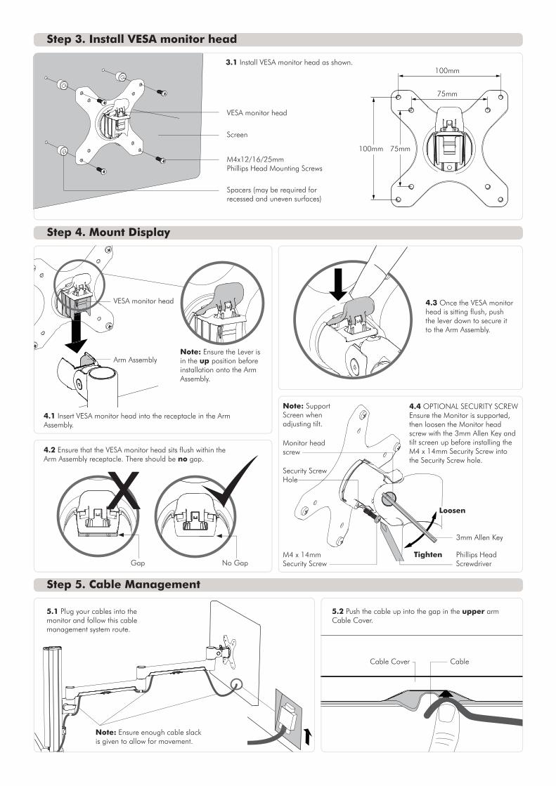
Spacers (may be required for recessed and uneven surfaces)
VESA monitor head
VESA monitor head
Gap No Gap
3mm Allen Key
Phillips Head Screwdriver
Loosen
Tighten
Security Screw Hole
M4 x 14mm Security Screw
Monitor head screw
Arm Assembly
Screen
M4x12/16/25mmPhillips Head Mounting Screws
100mm 75mm
75mm
Step 3. Install VESA monitor head
Step 4. Mount Display
4.1 Insert VESA monitor head into the receptacle in the Arm Assembly.
4.2 Ensure that the VESA monitor head sits flush within the Arm Assembly receptacle. There should be no gap.
4.3 Once the VESA monitor head is sitting flush, push the lever down to secure it to the Arm Assembly.
4.4 OPTIONAL SECURITY SCREWEnsure the Monitor is supported, then loosen the Monitor head screw with the 3mm Allen Key and tilt screen up before installing the M4 x 14mm Security Screw into the Security Screw hole.
Step 5. Cable Management
Note: Ensure the Lever is in the up position before installation onto the Arm Assembly.
3.1 Install VESA monitor head as shown.
Cable Cover Cable
5.1 Plug your cables into the monitor and follow this cable management system route.
5.2 Push the cable up into the gap in the upper arm Cable Cover.
Note: Ensure enough cable slack is given to allow for movement.
Note: Support Screen when adjusting tilt.

5.3 Whilst maintaining pressure on the cable, slide the cable into the groove and follow it up.
5.4 Whilst maintaining pressure on the cable, slide the cable into the groove and follow it down.
5.5 At the Elbow, pull one side of the clip down and push the cable through the gap.
Step 5. Cable Management (cont.)
Cable Cover5.9 Under the Channel Clamp, pull one side of the clip down and push the cable through the gap.
5.11 OPTIONALA. Loop cable and insert into Cable Cover.
Note: Choose 5.11 and/or 5.12 for your column cable management depending on your needs.
5.11 OPTIONAL B. Push the Cable down into either side of the Cable Cover until it reaches the bottom.
5.10 OPTIONALTo reposition the Cable Cover, pull it straight up and out of the post and insert it into any of the available channels.
Note: The Cable Cover shown, only comes with SP40 or SP75 posts.)
5.7 Whilst maintaining pressure on the cable, slide the cable into the groove and follow it up.
5.8 Whilst maintaining pressure on the cable, slide the cable into the groove and follow it down.
Cable Cover Cable
5.6 Push the cable up into the gap in the lower arm Cable Cover.
Optional Cable Cover Positions

Post Cable Clip
10º - 20º
5º 15º
(h)
5.12 OPTIONAL (NOTE: Cable clips only come with SP40 and SP75 Posts or separately in SC4 accessory pack)
A. Push the cable down into the CabCablele Clip.
5.12 OPTIONAL B. Insert one side of the Cable Clip into the Channel on the Post assembly or Wall channel, before pushing the other side in.
3mm Allen Key
Step 6. Adjusting the Display Bracket
Tighten
Loosen
Portrait/Landscape Tilt (Screen angle up/down) Pan (Screen angle left/right)
Post Cable Cover Post Cable Cover
Ergonomic Guidelines
Many experts believe that the extended use of any computer screen has the potential to cause serious injury to your eyes, neck and back. This can be largely avoided by correctly positioning your display.
Viewing angle: Ergonomists recommend that the optimal position of your display should be slightly below eye level. When looking at the display’s centre the user should have a downward visual angle of approximately 10°-20°.
Height: As a guide, the height (h) of your display should approximately be as follows: - Tall Male (Max): 560mm (22”) - Short Male (Min): 368mm (14.5”) - Tall Female (Max): 520mm (20.5”) - Short Female (Min) 356mm (14”)
Distance: For visual comfort, a viewing distance (d) between 500mm (20”) to 750mm (29.5”) is recommended.
Tilt Angle: Angular adjustments to reduce reflection on your monitor should range between 5° forward tilt to 15° backward tilt.
Installation Complete
No portion of this document or any artwork contained herein should be reproduced in any way without the express written consent of Atdec Pty Ltd.Due to continuing product development, the manufacturer reserves the right to alter specifications without notice. Published 21.02.14 ©
For a triple configuration Atdec recommends using:
No Allen Key necessary No Allen Key necessaryNote: Support Screen when adjusting tilt.