Embed Size (px)
Citation preview
Switching Power Supply S82J1
Switching Power Supply
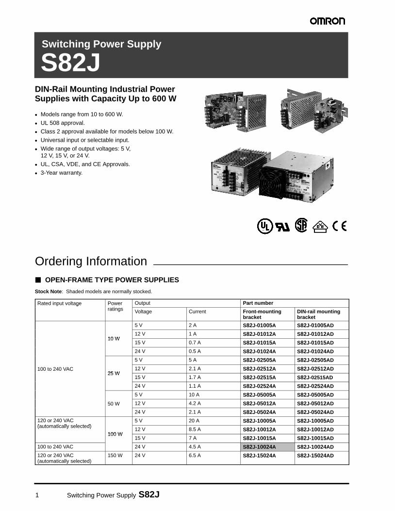
S82JDIN-Rail Mounting Industrial PowerSupplies with Capacity Up to 600 W
� Models range from 10 to 600 W.
� UL 508 approval.
� Class 2 approval available for models below 100 W.
� Universal input or selectable input.
� Wide range of output voltages: 5 V, 12 V, 15 V, or 24 V.
� UL, CSA, VDE, and CE Approvals.
� 3-Year warranty.
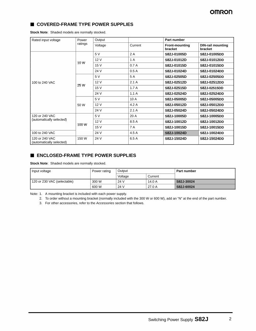
Ordering Information� OPEN-FRAME TYPE POWER SUPPLIES
Stock Note: Shaded models are normally stocked.
Rated input voltage Powerratings
Output Part numberRated input voltage Powerratings Voltage Current Front-mounting
bracketDIN-rail mountingbracket
5 V 2 A S82J-01005A S82J-01005AD
10 W12 V 1 A S82J-01012A S82J-01012AD
10 W15 V 0.7 A S82J-01015A S82J-01015AD
24 V 0.5 A S82J-01024A S82J-01024AD
5 V 5 A S82J-02505A S82J-02505AD
100 to 240 VAC25 W
12 V 2.1 A S82J-02512A S82J-02512AD100 to 240 VAC25 W
15 V 1.7 A S82J-02515A S82J-02515AD
24 V 1.1 A S82J-02524A S82J-02524AD
5 V 10 A S82J-05005A S82J-05005AD
50 W 12 V 4.2 A S82J-05012A S82J-05012AD50 W
24 V 2.1 A S82J-05024A S82J-05024AD
120 or 240 VAC(automatically selected)
5 V 20 A S82J-10005A S82J-10005AD120 or 240 VAC(automatically selected)
100 W12 V 8.5 A S82J-10012A S82J-10012AD
100 W15 V 7 A S82J-10015A S82J-10015AD
100 to 240 VAC 24 V 4.5 A S82J-10024A S82J-10024AD
120 or 240 VAC(automatically selected)
150 W 24 V 6.5 A S82J-15024A S82J-15024AD
2Switching Power Supply S82J
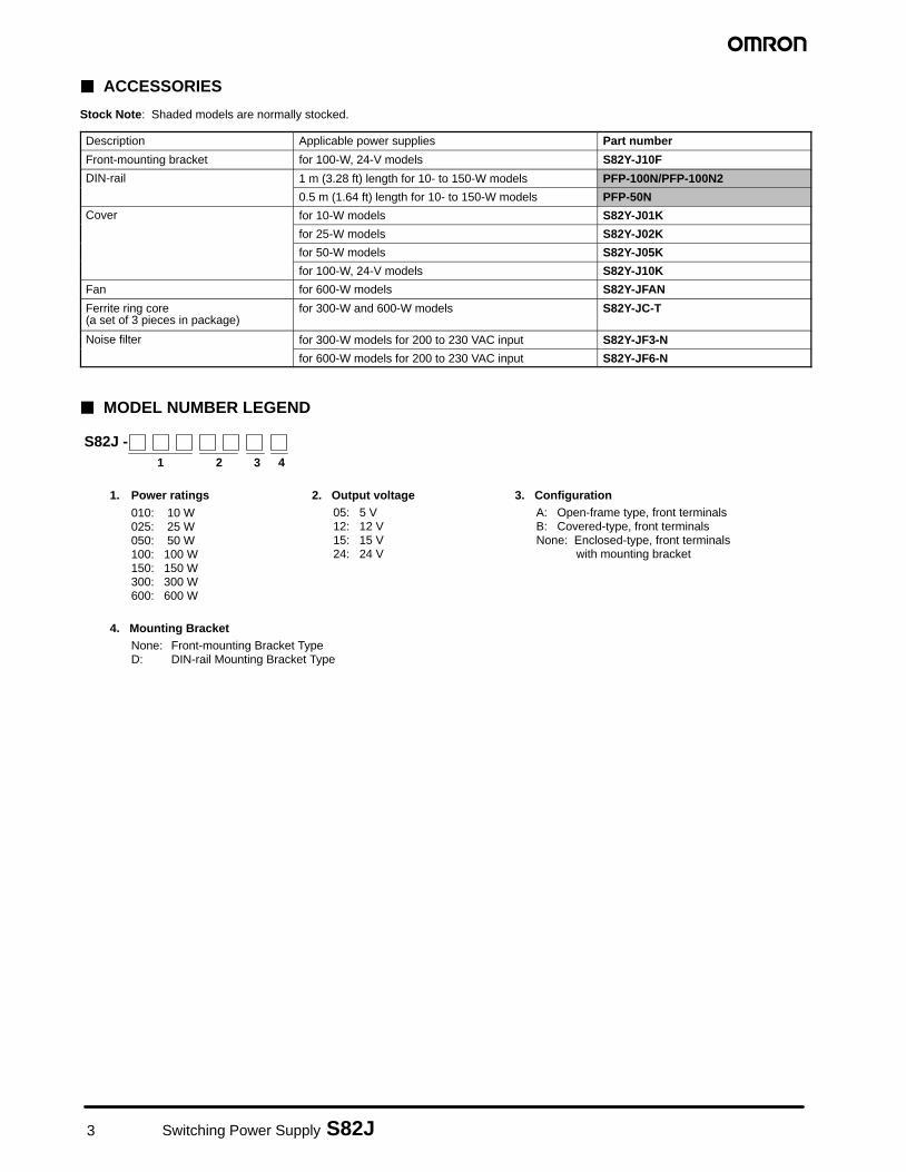
� COVERED-FRAME TYPE POWER SUPPLIES
Stock Note: Shaded models are normally stocked.
Rated input voltage Powerratings
Output Part numberRated input voltage Powerratings Voltage Current Front-mounting
bracketDIN-rail mountingbracket
5 V 2 A S82J-01005D S82J-01005DD
10 W12 V 1 A S82J-01012D S82J-01012DD
10 W15 V 0.7 A S82J-01015D S82J-01015DD
24 V 0.5 A S82J-01024D S82J-01024DD
5 V 5 A S82J-02505D S82J-02505DD
100 to 240 VAC25 W
12 V 2.1 A S82J-02512D S82J-02512DD100 to 240 VAC25 W
15 V 1.7 A S82J-02515D S82J-02515DD
24 V 1.1 A S82J-02524D S82J-02524DD
5 V 10 A S82J-05005D S82J-05005DD
50 W 12 V 4.2 A S82J-05012D S82J-05012DD50 W
24 V 2.1 A S82J-05024D S82J-05024DD
120 or 240 VAC(automatically selected)
5 V 20 A S82J-10005D S82J-10005DD120 or 240 VAC(automatically selected)
100 W12 V 8.5 A S82J-10012D S82J-10012DD
100 W15 V 7 A S82J-10015D S82J-10015DD
100 to 240 VAC 24 V 4.5 A S82J-10024D S82J-10024DD
120 or 240 VAC(automatically selected)
150 W 24 V 6.5 A S82J-15024D S82J-15024DD
� ENCLOSED-FRAME TYPE POWER SUPPLIES
Stock Note: Shaded models are normally stocked.
Input voltage Power rating Output Part numberInput voltage Power rating
Voltage Current
Part number
120 or 230 VAC (selectable) 300 W 24 V 14.0 A S82J-30024120 or 230 VAC (selectable)
600 W 24 V 27.0 A S82J-60024
Note: 1. A mounting bracket is included with each power supply.2. To order without a mounting bracket (normally included with the 300 W or 600 W), add an “N” at the end of the part number.3. For other accessories, refer to the Accessories section that follows.
3 Switching Power Supply S82J
� ACCESSORIES
Stock Note: Shaded models are normally stocked.
Description Applicable power supplies Part number
Front-mounting bracket for 100-W, 24-V models S82Y-J10F
DIN-rail 1 m (3.28 ft) length for 10- to 150-W models PFP-100N/PFP-100N2DIN-rail
0.5 m (1.64 ft) length for 10- to 150-W models PFP-50N
Cover for 10-W models S82Y-J01KCover
for 25-W models S82Y-J02K
for 50-W models S82Y-J05K
for 100-W, 24-V models S82Y-J10K
Fan for 600-W models S82Y-JFAN
Ferrite ring core(a set of 3 pieces in package)
for 300-W and 600-W models S82Y-JC-T
Noise filter for 300-W models for 200 to 230 VAC input S82Y-JF3-NNoise filter
for 600-W models for 200 to 230 VAC input S82Y-JF6-N
� MODEL NUMBER LEGEND
S82J - 1 32 4
3. ConfigurationA: Open-frame type, front terminalsB: Covered-type, front terminalsNone: Enclosed-type, front terminals
with mounting bracket
4. Mounting BracketNone: Front-mounting Bracket TypeD: DIN-rail Mounting Bracket Type
2. Output voltage05: 5 V12: 12 V15: 15 V24: 24 V
1. Power ratings010: 10 W025: 25 W050: 50 W100: 100 W150: 150 W300: 300 W600: 600 W
4Switching Power Supply S82J
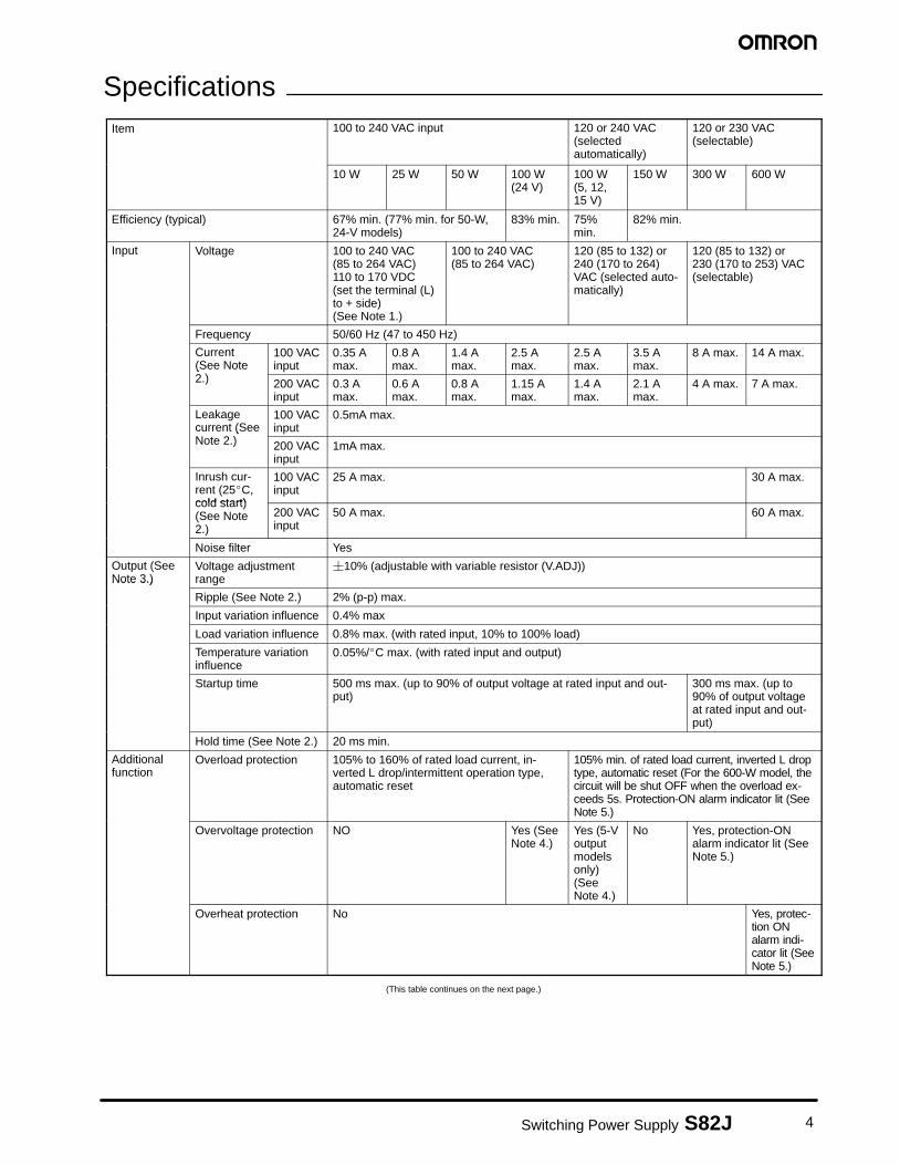
SpecificationsItem 100 to 240 VAC input 120 or 240 VAC
(selectedautomatically)
120 or 230 VAC(selectable)
10 W 25 W 50 W 100 W(24 V)
100 W(5, 12,15 V)
150 W 300 W 600 W
Efficiency (typical) 67% min. (77% min. for 50-W,24-V models)
83% min. 75%min.
82% min.
Input Voltage 100 to 240 VAC (85 to 264 VAC)110 to 170 VDC (set the terminal (L)to + side) (See Note 1.)
100 to 240 VAC (85 to 264 VAC)
120 (85 to 132) or240 (170 to 264)VAC (selected auto-matically)
120 (85 to 132) or 230 (170 to 253) VAC(selectable)
Frequency 50/60 Hz (47 to 450 Hz)
Current(See Note2.)
100 VACinput
0.35 Amax.
0.8 Amax.
1.4 Amax.
2.5 Amax.
2.5 Amax.
3.5 Amax.
8 A max. 14 A max.(See Note2.) 200 VAC
input0.3 Amax.
0.6 Amax.
0.8 Amax.
1.15 Amax.
1.4 Amax.
2.1 Amax.
4 A max. 7 A max.
Leakagecurrent (SeeNote 2.)
100 VACinput
0.5mA max.current (SeeNote 2.) 200 VAC
input1mA max.
Inrush cur-rent (25�C,cold start)
100 VACinput
25 A max. 30 A max.
cold start)(See Note2.)
200 VACinput
50 A max. 60 A max.
Noise filter Yes
Output (SeeNote 3.)
Voltage adjustmentrange
�10% (adjustable with variable resistor (V.ADJ))Note 3.)
Ripple (See Note 2.) 2% (p-p) max.
Input variation influence 0.4% max
Load variation influence 0.8% max. (with rated input, 10% to 100% load)
Temperature variationinfluence
0.05%/�C max. (with rated input and output)
Startup time 500 ms max. (up to 90% of output voltage at rated input and out-put)
300 ms max. (up to90% of output voltageat rated input and out-put)
Hold time (See Note 2.) 20 ms min.
Additionalfunction
Overload protection 105% to 160% of rated load current, in-verted L drop/intermittent operation type,automatic reset
105% min. of rated load current, inverted L droptype, automatic reset (For the 600-W model, thecircuit will be shut OFF when the overload ex-ceeds 5s. Protection-ON alarm indicator lit (SeeNote 5.)
Overvoltage protection NO Yes (SeeNote 4.)
Yes (5-Voutputmodelsonly)(SeeNote 4.)
No Yes, protection-ONalarm indicator lit (SeeNote 5.)
Overheat protection No Yes, protec-tion ONalarm indi-cator lit (SeeNote 5.)
(This table continues on the next page.)
5 Switching Power Supply S82J
Specifications Table – continued from previous page
Item 100 to 240 VAC input 120 or 240 VAC(selectedautomatically)
120 or 230 VAC(selectable)
10 W 25 W 50 W 100 W(24V)
100 W(5, 12,15 V)
150 W 300 W 600 W
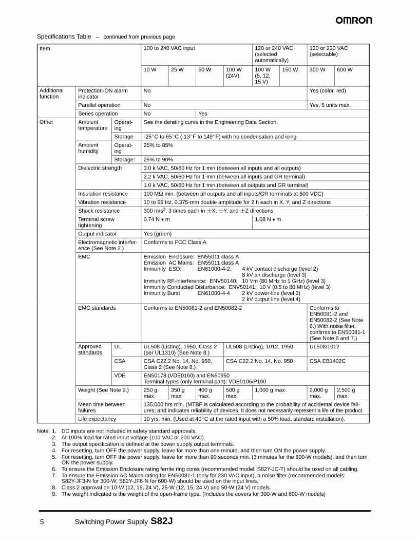
Additionalfunction
Protection-ON alarmindicator
No Yes (color, red)function
Parallel operation No Yes, 5 units max.
Series operation No Yes
Other Ambienttemperature
Operat-ing
See the derating curve in the Engineering Data Section.temperature
Storage -25�C to 65�C (-13�F to 149�F) with no condensation and icing
Ambienthumidity
Operat-ing
25% to 85%humidity
Storage: 25% to 90%
Dielectric strength 3.0 k VAC, 50/60 Hz for 1 min (between all inputs and all outputs)Dielectric strength
2.2 k VAC, 50/60 Hz for 1 min (between all inputs and GR terminal)
1.0 k VAC, 50/60 Hz for 1 min (between all outputs and GR terminal)
Insulation resistance 100 M� min. (between all outputs and all inputs/GR terminals at 500 VDC)
Vibration resistance 10 to 55 Hz, 0.375-mm double amplitude for 2 h each in X, Y, and Z directions
Shock resistance 300 m/s2, 3 times each in �X, �Y, and �Z directions
Terminal screwtightening
0.74 N � m 1.08 N � m
Output indicator Yes (green)
Electromagnetic interfer-ence (See Note 2.)
Conforms to FCC Class A
EMC Emission Enclosure: EN55011 class AEmission AC Mains: EN55011 class AImmunity ESD: EN61000-4-2: 4 kV contact discharge (level 2)
8 kV air discharge (level 3)Immunity RF-interference: ENV50140: 10 Vm (80 MHz to 1 GHz) (level 3)Immunity Conducted Disturbance: ENV50141: 10 V (0.5 to 80 MHz) (level 3)Immunity Burst EN61000-4-4 2 kV power-line (level 3)
2 kV output line (level 4)
EMC standards Conforms to EN50081-2 and EN50082-2 Conforms toEN50081-2 andEN50082-2 (See Note6.) With noise filter,confirms to EN50081-1(See Note 6 and 7.)
Approvedstandards
UL UL508 (Listing), 1950, Class 2(per UL1310) (See Note 8.)
UL508 (Listing), 1012, 1950 UL508/1012standards
CSA CSA C22.2 No. 14, No. 950,Class 2 (See Note 8.)
CSA C22.2 No. 14, No. 950 CSA EB1402C
VDE EN50178 (VDE0160) and EN60950Terminal types (only terminal part): VDE0106/P100
Weight (See Note 9.) 250 gmax.
350 gmax.
400 gmax.
500 gmax.
1,000 g max 2,000 gmax.
2,500 gmax.
Mean time betweenfailures
135,000 hrs min. (MTBF is calculated according to the probability of accidental device fail-ures, and indicates reliability of devices. It does not necessarily represent a life of the product.
Life expectancy 10 yrs. min. (Used at 40�C at the rated input with a 50% load, standard installation).
Note: 1. DC inputs are not included in safety standard approvals.2. At 100% load for rated input voltage (100 VAC or 200 VAC)3. The output specification is defined at the power supply output terminals.4. For resetting, turn OFF the power supply, leave for more than one minute, and then turn ON the power supply.5. For resetting, turn OFF the power supply, leave for more than 90 seconds min. (3 minutes for the 600-W models), and then turn
ON the power supply.6. To ensure the Emission Enclosure rating ferrite ring cores (recommended model: S82Y-JC-T) should be used on all cabling.7. To ensure the Emission AC Mains rating for EN50081-1 (only for 230 VAC input), a noise filter (recommended models:
S82Y-JF3-N for 300-W, S82Y-JF6-N for 600-W) should be used on the input lines.8. Class 2 approval on 10-W (12, 15, 24 V), 25-W (12, 15, 24 V) and 50-W (24 V) models.9. The weight indicated is the weight of the open-frame type. (Includes the covers for 300-W and 600-W models)
6Switching Power Supply S82J
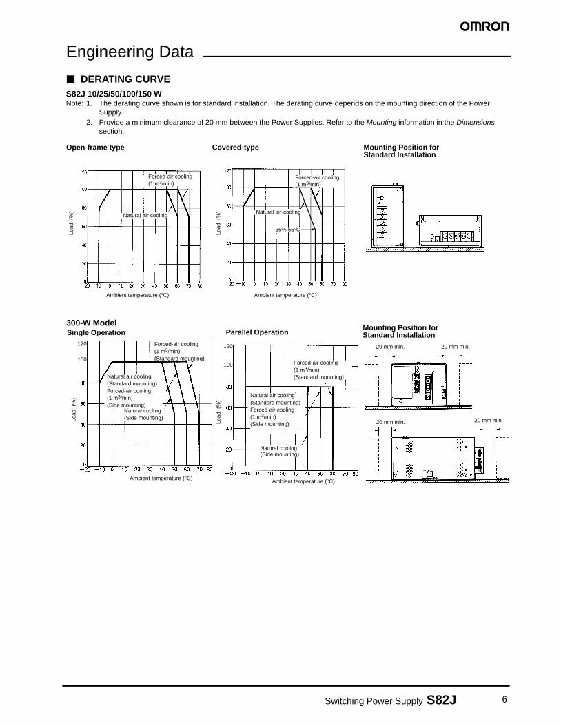
Engineering Data
� DERATING CURVES82J 10/25/50/100/150 WNote: 1. The derating curve shown is for standard installation. The derating curve depends on the mounting direction of the Power
Supply.2. Provide a minimum clearance of 20 mm between the Power Supplies. Refer to the Mounting information in the Dimensions
section.
Open-frame type
Load
(%
)
Ambient temperature (°C)
Covered-type
Load
(%
)
Ambient temperature (°C)
Mounting Position forStandard Installation
Natural air cooling
Forced-air cooling (1 m3/min)
Natural air-cooling
55% 55°C
Forced-air cooling(1 m3/min)
300-W ModelParallel Operation
Mounting Position for Standard Installation
Load
(%
)
Ambient temperature (°C)
Forced-air cooling (1 m3/min) (Standard mounting)
Natural air cooling(Standard mounting)Forced-air cooling (1 m3/min)(Side mounting)
Single Operation
Load
(%
)
Ambient temperature (°C)
Natural air cooling(Standard mounting)Forced-air cooling (1 m3/min)(Side mounting)
Natural cooling(Side mounting)
Forced-air cooling (1 m3/min) (Standard mounting)
20 mm min. 20 mm min.
20 mm min. 20 mm min.
Natural cooling(Side mounting)
120 120
100100
7 Switching Power Supply S82J
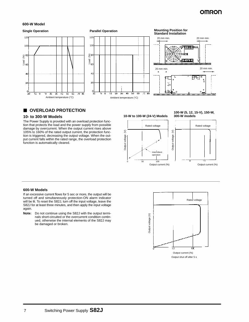
600-W Model
Single Operation Parallel Operation
Load
(%
)
Ambient temperature (°C)
Load
(%
)
Ambient temperature (°C)
Mounting Position for Standard Installation
20 mm min. 20 mm min.
20 mm min. 20 mm min.
120 120
100 100
Out
put v
olta
ge (
V)
Output current (%)
Intermittentoperation
500 100
Rated voltage
� OVERLOAD PROTECTION10- to 300-W ModelsThe Power Supply is provided with an overload protection func-tion that protects the load and the power supply from possibledamage by overcurrent. When the output current rises above105% to 160% of the rated output current, the protection func-tion is triggered, decreasing the output voltage. When the out-put current falls within the rated range, the overload protectionfunction is automatically cleared.
Out
put v
olta
ge (
V)
Output current (%)
Rated voltage
100-W (5, 12, 15-V), 150-W,300-W models10-W to 100-W (24-V) Models
600-W ModelsIf an excessive current flows for 5 sec or more, the output will beturned off and simultaneously protection-ON alarm indicatorwill be lit. To reset the S82J, turn off the input voltage, leave theS82J for at least three minutes, and then apply the input voltageagain.
Note: Do not continue using the S82J with the output termi-nals short-circuited or the overcurrent condition contin-ued, otherwise the internal elements of the S82J maybe damaged or broken.
Out
put v
olta
ge (
V)
Output current (%)
Rated voltage
Output shut off after 5 s
8Switching Power Supply S82J
Out
put v
olta
ge (
V)
Overvoltageprotectionoperating
Approx.20%
10%
–10%
Rated outputvoltage Variable range
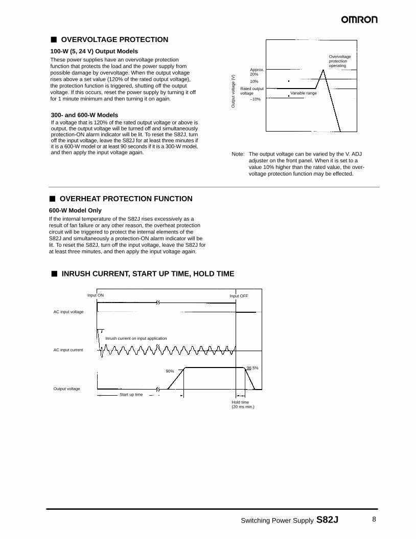
Note: The output voltage can be varied by the V. ADJadjuster on the front panel. When it is set to avalue 10% higher than the rated value, the over-voltage protection function may be effected.
� OVERVOLTAGE PROTECTION
100-W (5, 24 V) Output ModelsThese power supplies have an overvoltage protectionfunction that protects the load and the power supply frompossible damage by overvoltage. When the output voltagerises above a set value (120% of the rated output voltage),the protection function is triggered, shutting off the outputvoltage. If this occurs, reset the power supply by turning it offfor 1 minute minimum and then turning it on again.
300- and 600-W ModelsIf a voltage that is 120% of the rated output voltage or above isoutput, the output voltage will be turned off and simultaneouslyprotection-ON alarm indicator will be lit. To reset the S82J, turnoff the input voltage, leave the S82J for at least three minutes ifit is a 600-W model or at least 90 seconds if it is a 300-W model,and then apply the input voltage again.
� OVERHEAT PROTECTION FUNCTION
600-W Model OnlyIf the internal temperature of the S82J rises excessively as aresult of fan failure or any other reason, the overheat protectioncircuit will be triggered to protect the internal elements of theS82J and simultaneously a protection-ON alarm indicator will belit. To reset the S82J, turn off the input voltage, leave the S82J forat least three minutes, and then apply the input voltage again.
Input OFFInput ON
AC input voltage
AC input current
Output voltage
Inrush current on input application
Start up time
Hold time(20 ms min.)
90%96.5%
� INRUSH CURRENT, START UP TIME, HOLD TIME
9 Switching Power Supply S82J
Installation
600-W Models
+V
+V
�V
�V
5
6
1AC (L)
AC (N)2
4
3GR
300-W Models
1 6 5 7
8
4 2 3
AC (L)
AC (N)GR
8
Side view
7
Side view
5
6
1
3
2
+V
–V
AC (L)
AC (N)
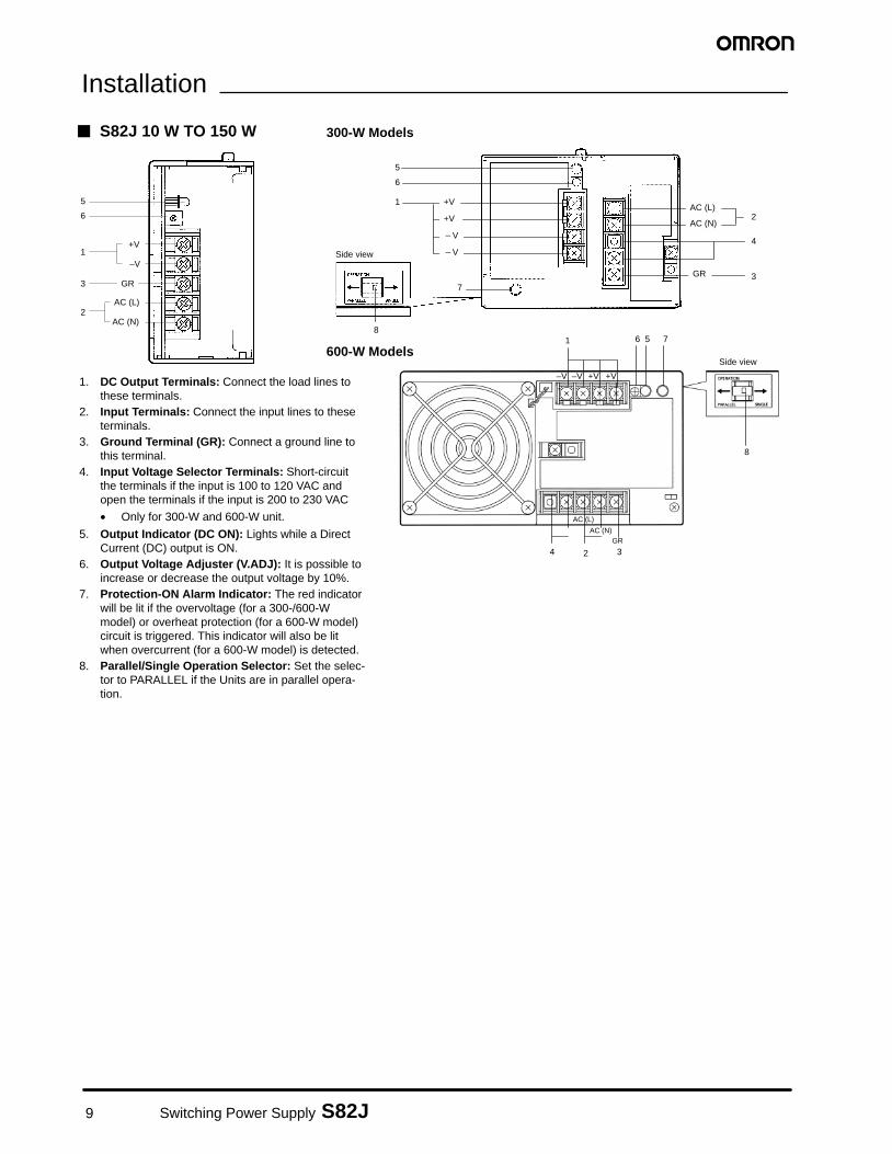
� S82J 10 W TO 150 W
GR
1. DC Output Terminals: Connect the load lines tothese terminals.
2. Input Terminals: Connect the input lines to theseterminals.
3. Ground Terminal (GR): Connect a ground line tothis terminal.
4. Input Voltage Selector Terminals: Short-circuitthe terminals if the input is 100 to 120 VAC andopen the terminals if the input is 200 to 230 VAC
• Only for 300-W and 600-W unit.
5. Output Indicator (DC ON): Lights while a DirectCurrent (DC) output is ON.
6. Output Voltage Adjuster (V.ADJ): It is possible toincrease or decrease the output voltage by 10%.
7. Protection-ON Alarm Indicator: The red indicatorwill be lit if the overvoltage (for a 300-/600-Wmodel) or overheat protection (for a 600-W model)circuit is triggered. This indicator will also be litwhen overcurrent (for a 600-W model) is detected.
8. Parallel/Single Operation Selector: Set the selec-tor to PARALLEL if the Units are in parallel opera-tion.
–V –V +V +V
10Switching Power Supply S82J
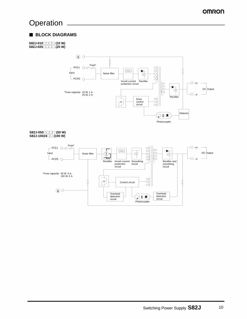
Operation� BLOCK DIAGRAMS
Drivecontrolcircuit
+V
–V
DC Output
AC(L)
AC(N)
Fuse*
Noise filter
Inrush currentprotection circuit
Rectifier
Rectifier
Detector
Photocoupler
Input
*Fuse capacity: 10 W, 1 A25 W, 2 A
S82J-010���� (10 W)S82J-025���� (25 W)
S82J-050���� (50 W)S82J-10024�� (100 W)
Input
AC(L)
AC(N)
Fuse*
Noise filter
Control circuit
Overloaddetectioncircuit
Photocoupler
Overloaddetectioncircuit
+V
–V
DC Output
Inrush currentprotectioncircuit
Rectifier Smoothingcircuit
Rectifier andsmoothingcircuit
*Fuse capacity: 50 W, 3 A,100 W, 5 A
11 Switching Power Supply S82J
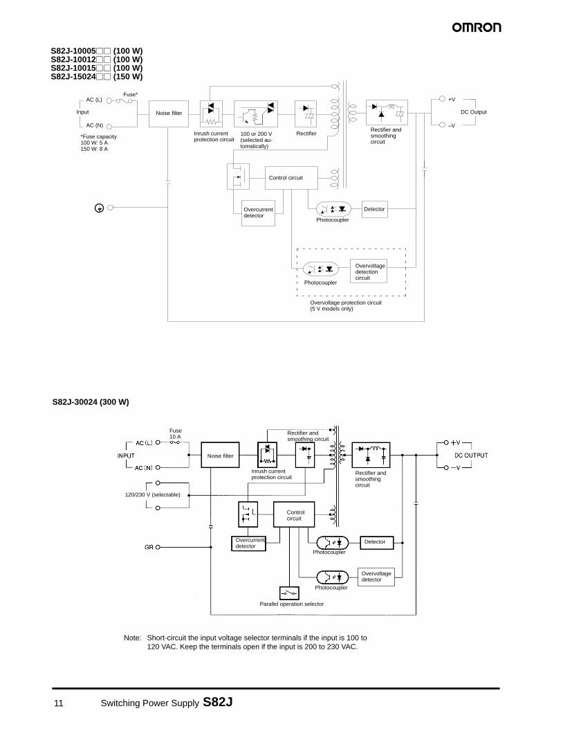
S82J-10005�� (100 W)S82J-10012�� (100 W)S82J-10015�� (100 W)S82J-15024�� (150 W)
+V
–V
DC OutputInput
AC (L)
AC (N)
Fuse*
Noise filter
Inrush currentprotection circuit
Rectifier
Control circuit
Overcurrentdetector
Rectifier andsmoothingcircuit
Detector
Photocoupler
100 or 200 V(selected au-tomatically)
*Fuse capacity100 W: 5 A150 W: 8 A
Overvoltagedetectioncircuit
Photocoupler
Overvoltage protection circuit(5 V models only)
S82J-30024 (300 W)
Parallel operation selector
120/230 V (selectable)
Note: Short-circuit the input voltage selector terminals if the input is 100 to120 VAC. Keep the terminals open if the input is 200 to 230 VAC.
Fuse 10 A
Noise filter
Inrush currentprotection circuit
Rectifier andsmoothingcircuit
Detector
Photocoupler
Overvoltagedetector
Photocoupler
Control circuit
Overcurrent detector
Rectifier andsmoothing circuit
12Switching Power Supply S82J
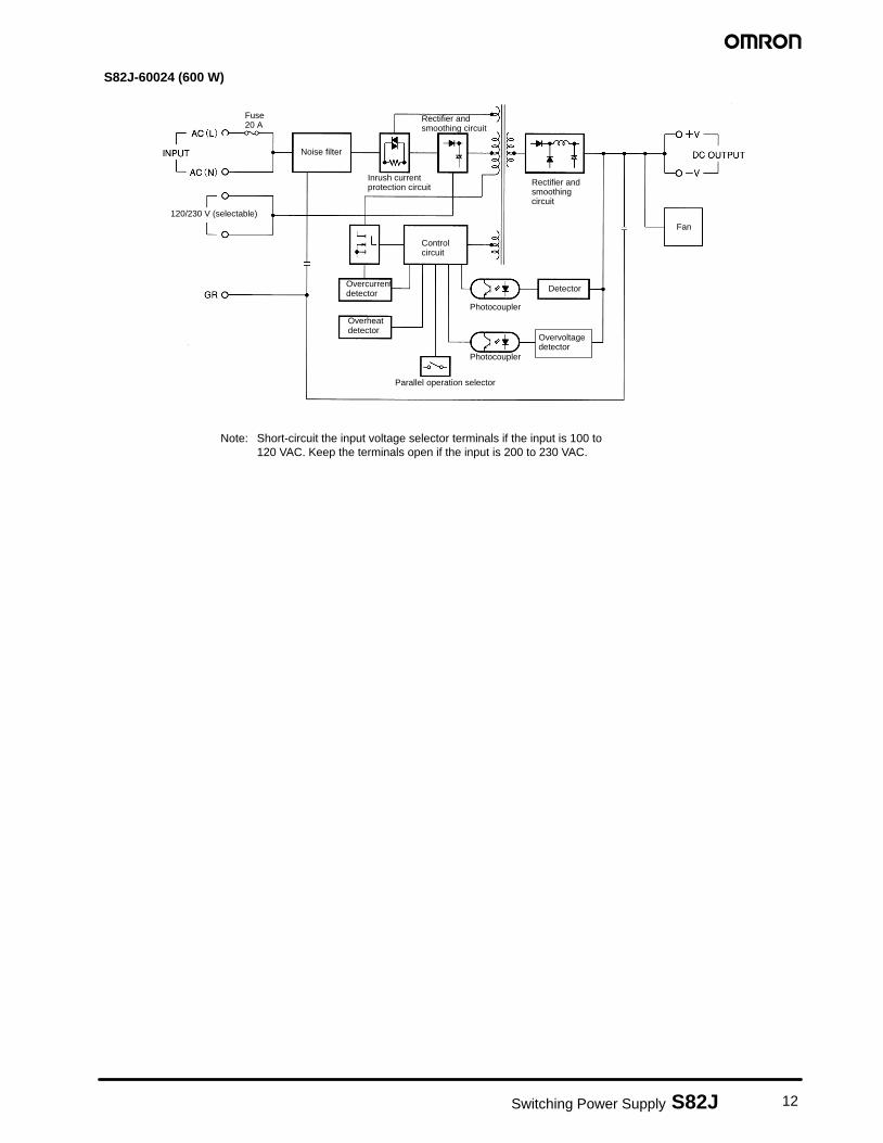
S82J-60024 (600 W)
Parallel operation selector
120/230 V (selectable)
Fuse 20 A
Noise filter
Inrush currentprotection circuit Rectifier and
smoothingcircuit
Detector
Photocoupler
Photocoupler
Control circuit
Overcurrent detector
Fan
Overheat detector
Overvoltagedetector
Rectifier andsmoothing circuit
Note: Short-circuit the input voltage selector terminals if the input is 100 to120 VAC. Keep the terminals open if the input is 200 to 230 VAC.
13 Switching Power Supply S82J
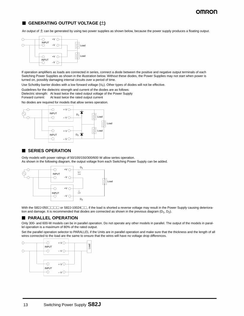
� GENERATING OUTPUT VOLTAGE (±)
An output of ± can be generated by using two power supplies as shown below, because the power supply produces a floating output.
INPUT
INPUT
+V
–V
+V
–V
Load
Load
If operation amplifiers as loads are connected in series, connect a diode between the positive and negative output terminals of eachSwitching Power Supplies as shown in the illustration below. Without these diodes, the Power Supplies may not start when power isturned on, possibly damaging internal circuits over a period of time.
Use Schottky barrier diodes with a low forward voltage (VF). Other types of diodes will not be effective.
Guidelines for the dielectric strength and current of the diodes are as follows:Dielectric strength: At least twice the rated output voltage of the Power SupplyForward current: At least twice the rated output current
No diodes are required for models that allow series operation.
INPUT
+ V
– V
+ V
– V
INPUT
D1
D2
Load
Load
Load
� SERIES OPERATION
Only models with power ratings of 50/100/150/300/600 W allow series operation.As shown in the following diagram, the output voltage from each Switching Power Supply can be added.
INPUT
+V
–V
+V
–VINPUT
Load
D1
D2
With the S82J-050���� or S82J-10024��, if the load is shorted a reverse voltage may result in the Power Supply causing deteriora-tion and damage. It is recommended that diodes are connected as shown in the previous diagram (D1, D2).
� PARALLEL OPERATIONOnly 300- and 600-W models can be in parallel operation. Do not operate any other models in parallel. The output of the models in paral-lel operation is a maximum of 80% of the rated output.
Set the parallel operation selector to PARALLEL if the Units are in parallel operation and make sure that the thickness and the length of allwires connected to the load are the same to ensure that the wires will have no voltage drop differences.
INPUT
+ V
– V
+ V
– V
INPUT
Load
14Switching Power Supply S82J
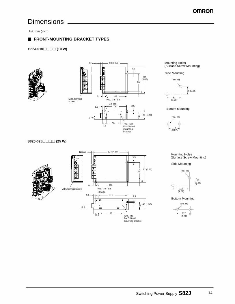
DimensionsUnit: mm (inch)
� FRONT-MOUNTING BRACKET TYPES
S82J-010���� (10 W)
Mounting Holes(Surface Screw Mounting)
Side Mounting
Bottom Mounting
3.5
90 (3.54)
97(3.82)
65
5
82Two, 3.5 dia.
3.5 dia.786.5
M3.5 terminalscrew
3.5
2835 (1.38)
50
17.5
15Two, M3 For DIN-railmountingbracket
12max.
5 82(3.23)
65 (2.56)
Two, M3
78(3.07)
Two, M3
S82J-025���� (25 W)
M3.5 terminal screw Two, 3.5 dia.
Two, M3 For DIN-railmounting bracket
124 (4.88)
3.5
97 (3.82)65
28 40 (1.57)
3.5112
3.5 dia.
12max.
17.5
21.583
6.5
5 116
6
Mounting Holes(Surface Screw Mounting)
Side Mounting
Bottom Mounting
112(4.41)
Two, M3
Two, M3
65(2.56)
116(4.57)
15 Switching Power Supply S82J
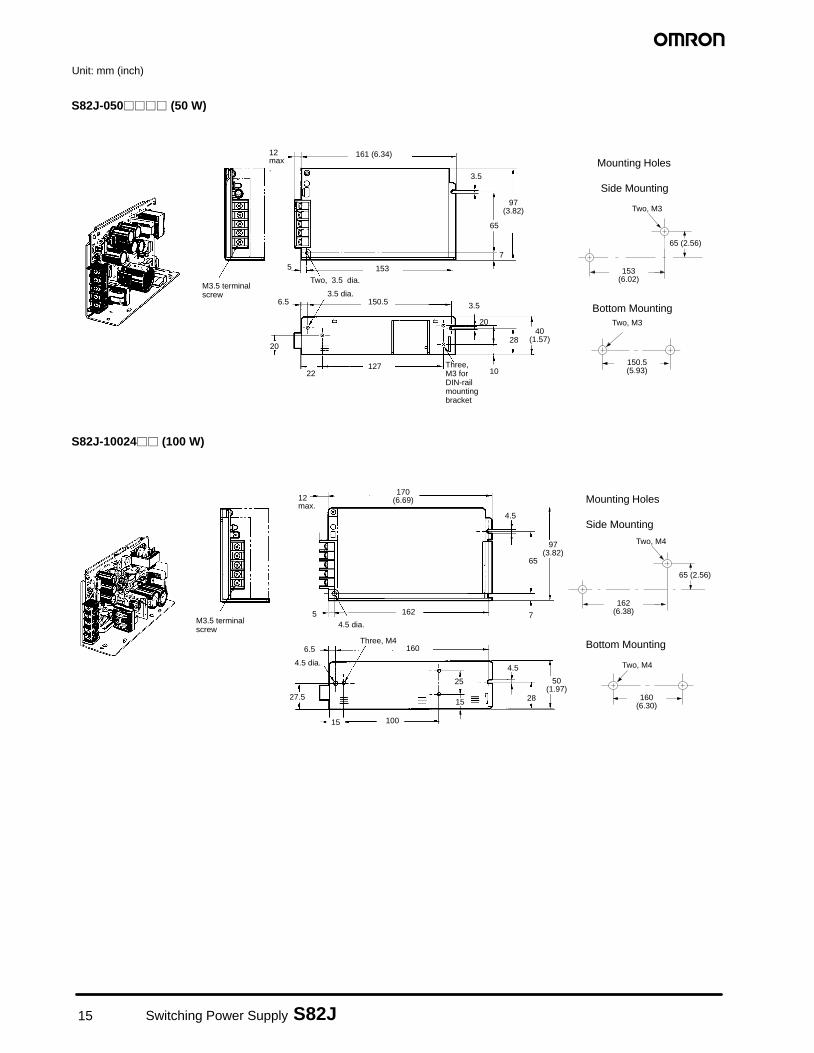
Unit: mm (inch)
S82J-050���� (50 W)
Mounting Holes
Side Mounting
Bottom Mounting
97(3.82)
65
3.5
161 (6.34)12max.
M3.5 terminalscrew
5
6.5
22127 Three,
M3 for DIN-railmountingbracket
150.5
153
3.5
10
2840
(1.57)
Two, 3.5 dia.
3.5 dia.
7
153(6.02)
Two, M3
150.5(5.93)
65 (2.56)
Two, M3
20
20
M3.5 terminalscrew
170(6.69)12
max.4.5
97(3.82)
65
7162
160
100
15
25
4.5
28
50(1.97)
Three, M46.5
4.5 dia.
27.5
15
4.5 dia.5
162(6.38)
65 (2.56)
Two, M4
Two, M4
160(6.30)
Mounting Holes
Side Mounting
Bottom Mounting
S82J-10024�� (100 W)
16Switching Power Supply S82J
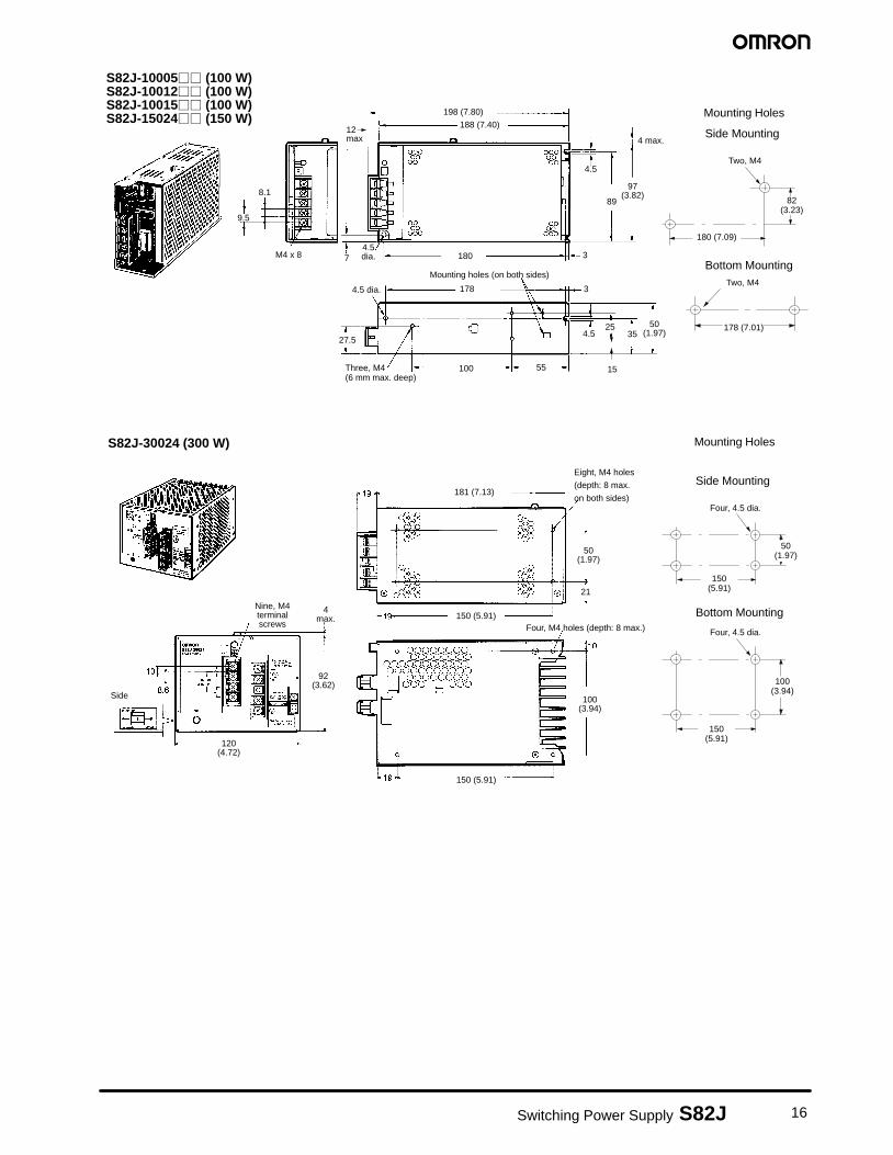
S82J-10005�� (100 W)S82J-10012�� (100 W)S82J-10015�� (100 W)S82J-15024�� (150 W)
198 (7.80)
188 (7.40)
180
4 max.
4.5
97(3.82)
50(1.97)4.5
89
3525
55100
27.5
7
178 3
3
8.1
9.5
M4 x 8
Three, M4(6 mm max. deep)
4.5 dia.
4.5dia.
Mounting holes (on both sides)
Mounting Holes12max.
15
Side Mounting
Bottom Mounting
180 (7.09)
82(3.23)
Two, M4
178 (7.01)
Two, M4
S82J-30024 (300 W)
Eight, M4 holes
(depth: 8 max.
on both sides)
Four, M4 holes (depth: 8 max.)
Nine, M4terminalscrews
Side
4max.
181 (7.13)
50(1.97)
100(3.94)
120(4.72)
92(3.62)
150 (5.91)
21
150 (5.91)
Mounting Holes
Side Mounting
Bottom Mounting
150(5.91)
50(1.97)
Four, 4.5 dia.
100(3.94)
Four, 4.5 dia.
150(5.91)
17 Switching Power Supply S82J
Unit: mm (inch)
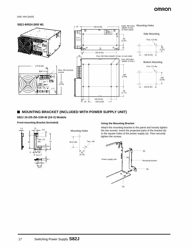
S82J-60024 (600 W)
Four, M4 holes (depth: 8 max. on one side)
Four, M4 holes (depth: 8 max.)
Eight, M4 holes (depth: 8 max.on both sides)
Nine, M4 terminalscrews
169 (6.65)31
150 (5.91)
50(1.97)
100(3.94)
45(1.77)
170 (6.69)
92(3.62)
150 (5.91)100 (3.94)34
Mounting Holes
Side Mounting
Bottom Mounting
Four, 4.5 dia.
Four, 4.5 dia.
150 (5.91)
100(3.94)
150 (5.91)
50(1.97)
� MOUNTING BRACKET (INCLUDED WITH POWER SUPPLY UNIT)
S82J 10-/25-/50-/100-W (24-V) Models
Front-mounting Bracket (Included)
Mounting Holes
Using the Mounting Bracket
Attach the mounting bracket to the panel and loosely tightenthe two screws. Insert the projected parts of the bracket (b)to the square holes of the power supply (a). Then securelytighten the screws.
1.5 11
9
60
5 20
31.5
15
20.5
4.7
4.611
74
15
Mounting bracket
(b)
(b)
(a)
(a)
Power supply unit
Two, M360 (2.36)
20(0.79)
4.6
Two, 3.5dia.
18Switching Power Supply S82J
5
1.5
2.52.5
20
6.5
11
23.5
38
153
5 dia.
6
1.5
17.5
6
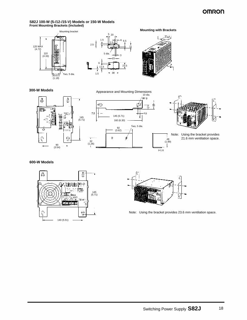
Front Mounting Brackets (Included)Mounting with Brackets
S82J 100-W (5-/12-/15-V) Models or 150-W Models
Mounting bracket
120 MAX(4.72)
Two, 5 dia.30±0.5(1.18)
110(4.33)
Appearance and Mounting Dimensions300-W Models
600-W Models
10 dia.
Two, 5 dia.
Note: Using the bracket provides21.6 mm ventilation space.
Note: Using the bracket provides 23.6 mm ventilation space.
145(5.71)
90(3.54)
32(1.26)
92(3.62)
48(1.89)
145 (5.71)
160 (6.30)
145(5.71)
140 (5.51)
t=1.6
19 Switching Power Supply S82J
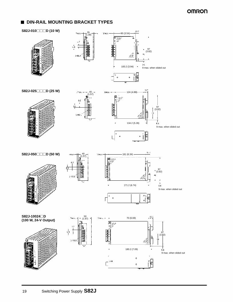
� DIN-RAIL MOUNTING BRACKET TYPES
S82J-010���D (10 W)
S82J-025���D (25 W)
9 max. when slided out
9 max. when slided out
97(3.82)
40(1.57)
124 (4.88)
97(3.82)
134.2 (5.28)
35(1.38) 90 (3.54)
100.2 (3.94)
S82J-050���D (50 W)
S82J-10024�D (100 W, 24-V Output)
9 max. when slided out
9 max. when slided out
40(1.57)
97(3.82)
171.2 (6.74)
161 (6.34)
97(3.82)
180.2 (7.09)
70 (6.69)50
(1.97)
20Switching Power Supply S82J
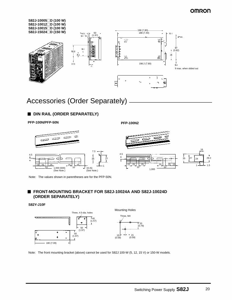
S82J-10005�D (100 W)S82J-10012�D (100 W)S82J-10015�D (100 W)S82J-15024�D (150 W)
9 max. when slided out
198 (7.80)188 (7.40)50
(1.97)
97(3.82)
198.2 (7.80)
Accessories (Order Separately)
� DIN RAIL (ORDER SEPARATELY)
4.5
15 25 25 25 2510 101,000 (500)
(See Note.)
7.3
35 27
115 (5)(See Note.)
Note: The values shown in parentheses are for the PFP-50N.
PFP-100N/PFP-50N
4.5
15 25 25 25 25 1510 10
1,000
35 27 24
16
29.2
1 1.5
PFP-100N2
� FRONT-MOUNTING BRACKET FOR S82J-10024A AND S82J-10024D(ORDER SEPARATELY)
S82Y-J10F
Mounting Holes
Note: The front mounting bracket (above) cannot be used for S82J 100-W (5, 12, 15 V) or 150-W models.
Three, 4.5-dia. holes
Three, M440
(1.57)
15(0.59)
15(0.59)
20(0.79)
50(1.97)
50(1.97)
180 (7.09)
21 Switching Power Supply S82J
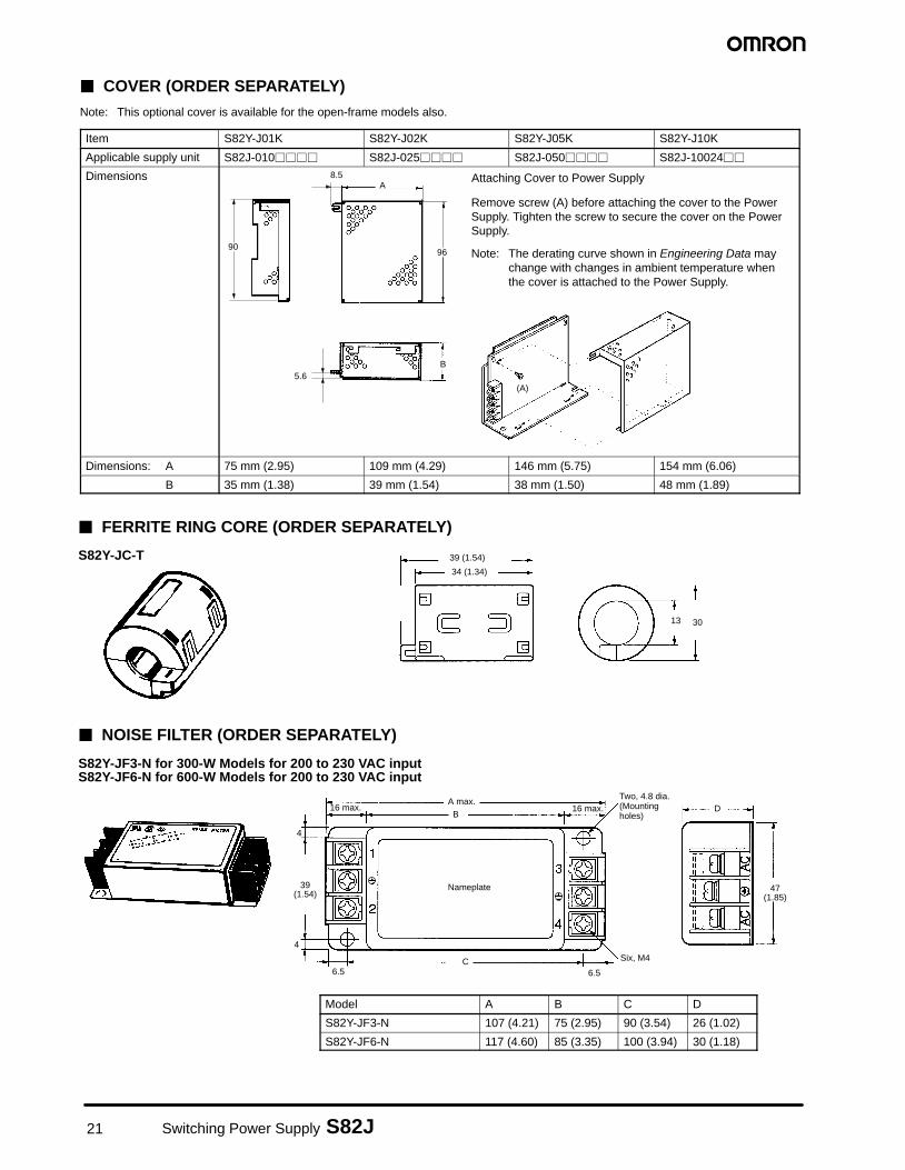
� COVER (ORDER SEPARATELY)
Note: This optional cover is available for the open-frame models also.
Item S82Y-J01K S82Y-J02K S82Y-J05K S82Y-J10K
Applicable supply unit S82J-010���� S82J-025���� S82J-050���� S82J-10024��
Dimensions
90
8.5A
96
B5.6
(A)
Remove screw (A) before attaching the cover to the PowerSupply. Tighten the screw to secure the cover on the PowerSupply.
Note: The derating curve shown in Engineering Data maychange with changes in ambient temperature whenthe cover is attached to the Power Supply.
Attaching Cover to Power Supply
Dimensions: A 75 mm (2.95) 109 mm (4.29) 146 mm (5.75) 154 mm (6.06)
B 35 mm (1.38) 39 mm (1.54) 38 mm (1.50) 48 mm (1.89)
� FERRITE RING CORE (ORDER SEPARATELY)
� NOISE FILTER (ORDER SEPARATELY)
13 30
39 (1.54)
34 (1.34)
39(1.54)
16 max.A max.
B
Two, 4.8 dia.(Mountingholes)
6.5
4
Six, M4
6.5C
16 max.
4
Nameplate
D
47(1.85)
S82Y-JC-T
S82Y-JF3-N for 300-W Models for 200 to 230 VAC inputS82Y-JF6-N for 600-W Models for 200 to 230 VAC input
Model A B C D
S82Y-JF3-N 107 (4.21) 75 (2.95) 90 (3.54) 26 (1.02)
S82Y-JF6-N 117 (4.60) 85 (3.35) 100 (3.94) 30 (1.18)
22Switching Power Supply S82J
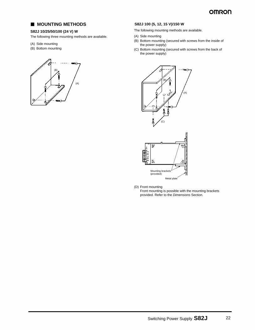
(A) Side mounting(B) Bottom mounting (secured with screws from the inside of
the power supply)(C) Bottom mounting (secured with screws from the back of
the power supply)
(D) Front mountingFront mounting is possible with the mounting bracketsprovided. Refer to the Dimensions Section.
(A)
(B)
(C)
The following mounting methods are available.
Mounting brackets(provided)
Metal plate
S82J 100 (5, 12, 15 V)/150 W
(A)
(B)
� MOUNTING METHODS
S82J 10/25/50/100 (24 V) WThe following three mounting methods are available.
(A) Side mounting(B) Bottom mounting
23 Switching Power Supply S82J
Certain Terms and Conditions of Sale1. Offer; Acceptance. These terms and conditions (these “Terms”) are
deemed part of all catalogs, manuals or other documents, whether elec-tronic or in writing, relating to the sale of goods or services (collectively, the“Goods”) by Omron Electronics LLC and its subsidiary companies (“Sell-er”). Seller hereby objects to any terms or conditions proposed in Buyer’spurchase order or other documents which are inconsistent with, or in addi-tion to, these Terms. Please contact your Omron representative to confirmany additional terms for sales from your Omron company.
2. Prices. All prices stated are current, subject to change without notice bySeller. Buyer agrees to pay the price in effect at time of shipment.
3. Discounts. Cash discounts, if any, will apply only on the net amount of in-voices sent to Buyer after deducting transportation charges, taxes and du-ties, and will be allowed only if (i) the invoice is paid according to Seller’spayment terms and (ii) Buyer has no past due amounts owing to Seller.
4. Orders. Seller will accept no order less than $200 net billing.5. Governmental Approvals. Buyer shall be responsible for, and shall bear
all costs involved in, obtaining any government approvals required for theimportation or sale of the Goods.
6. Taxes. All taxes, duties and other governmental charges (other than gen-eral real property and income taxes), including any interest or penaltiesthereon, imposed directly or indirectly on Seller or required to be collecteddirectly or indirectly by Seller for the manufacture, production, sale, deliv-ery, importation, consumption or use of the Goods sold hereunder (includ-ing customs duties and sales, excise, use, turnover and license taxes) shallbe charged to and remitted by Buyer to Seller.
7. Financial. If the financial position of Buyer at any time becomes unsatisfac-tory to Seller, Seller reserves the right to stop shipments or require satisfac-tory security or payment in advance. If Buyer fails to make payment orotherwise comply with these Terms or any related agreement, Seller may(without liability and in addition to other remedies) cancel any unshippedportion of Goods sold hereunder and stop any Goods in transit until Buyerpays all amounts, including amounts payable hereunder, whether or notthen due, which are owing to it by Buyer. Buyer shall in any event remainliable for all unpaid accounts.
8. Cancellation; Etc. Orders are not subject to rescheduling or cancellationunless Buyer indemnifies Seller fully against all costs or expenses arisingin connection therewith.
9. Force Majeure. Seller shall not be liable for any delay or failure in deliveryresulting from causes beyond its control, including earthquakes, fires,floods, strikes or other labor disputes, shortage of labor or materials, acci-dents to machinery, acts of sabotage, riots, delay in or lack of transportationor the requirements of any government authority.
10. Shipping; Delivery. Unless otherwise expressly agreed in writing by Seller:a. Shipments shall be by a carrier selected by Seller;b. Such carrier shall act as the agent of Buyer and delivery to such carrier
shall constitute delivery to Buyer;c. All sales and shipments of Goods shall be FOB shipping point (unless
otherwise stated in writing by Seller), at which point title to and all riskof loss of the Goods shall pass from Seller to Buyer, provided that Sellershall retain a security interest in the Goods until the full purchase priceis paid by Buyer;
d. Delivery and shipping dates are estimates only. e. Seller will package Goods as it deems proper for protection against
normal handling and extra charges apply to special conditions.11. Claims. Any claim by Buyer against Seller for shortage or damage to the
Goods occurring before delivery to the carrier must be presented in writingto Seller within 30 days of receipt of shipment and include the original trans-portation bill signed by the carrier noting that the carrier received the Goodsfrom Seller in the condition claimed.
12. Warranties. (a) Exclusive Warranty. Seller’s exclusive warranty is that theGoods will be free from defects in materials and workmanship for a periodof twelve months from the date of sale by Seller (or such other period ex-
pressed in writing by Seller). Seller disclaims all other warranties, expressor implied. (b) Limitations. SELLER MAKES NO WARRANTY OR REP-RESENTATION, EXPRESS OR IMPLIED, ABOUT NON–INFRINGE-MENT, MERCHANTABILITY OR FITNESS FOR A PARTICULAR PUR-POSE OF THE GOODS. BUYER ACKNOWLEDGES THAT IT ALONEHAS DETERMINED THAT THE GOODS WILL SUITABLY MEET THE RE-QUIREMENTS OF THEIR INTENDED USE. Seller further disclaims allwarranties and responsibility of any type for claims or expenses based oninfringement by the Goods or otherwise of any intellectual property right.(c) Buyer Remedy. Seller’s sole obligation hereunder shall be to replace(in the form originally shipped with Buyer responsible for labor charges forremoval or replacement thereof) the non–complying Good or, at Seller’selection, to repay or credit Buyer an amount equal to the purchase priceof the Good; provided that in no event shall Seller be responsible for war-ranty, repair, indemnity or any other claims or expenses regarding theGoods unless Seller’s analysis confirms that the Goods were properly han-dled, stored, installed and maintained and not subject to contamination,abuse, misuse or inappropriate modification. Return of any goods by Buy-er must be approved in writing by Seller before shipment. Seller shall notbe liable for the suitability or unsuitability or the results from the use ofGoods in combination with any electrical or electronic components, cir-cuits, system assemblies or any other materials or substances or environ-ments. Any advice, recommendations or information given orally or in writ-ing, are not to be construed as an amendment or addition to the abovewarranty.
13. Damage Limits; Etc. SELLER SHALL NOT BE LIABLE FOR SPECIAL, IN-DIRECT OR CONSEQUENTIAL DAMAGES, LOSS OF PROFITS ORPRODUCTION OR COMMERCIAL LOSS IN ANY WAY CONNECTEDWITH THE GOODS, WHETHER SUCH CLAIM IS BASED IN CONTRACT,WARRANTY, NEGLIGENCE OR STRICT LIABILITY. Further, in no eventshall liability of Seller exceed the individual price of the Good on which li-ability is asserted.
14. Indemnities. Buyer shall indemnify and hold harmless Seller, its affiliatesand its employees from and against all liabilities, losses, claims, costs andexpenses (including attorney’s fees and expenses) related to any claim, in-vestigation, litigation or proceeding (whether or not Seller is a party) whicharises or is alleged to arise from Buyer’s acts or omissions under theseTerms or in any way with respect to the Goods. Without limiting the forego-ing, Buyer (at its own expense) shall indemnify and hold harmless Sellerand defend or settle any action brought against Seller to the extent that itis based on a claim that any Good made to Buyer specifications infringedintellectual property rights of another party.
15. Property; Confidentiality. The intellectual property embodied in the Goodsis the exclusive property of Seller and its affiliates and Buyer shall not at-tempt to duplicate it in any way without the written permission of Seller.Notwithstanding any charges to Buyer for engineering or tooling, all engi-neering and tooling shall remain the exclusive property of Seller. All infor-mation and materials supplied by Seller to Buyer relating to the Goods areconfidential and proprietary, and Buyer shall limit distribution thereof to itstrusted employees and strictly prevent disclosure to any third party.
16. Miscellaneous. (a) Waiver. No failure or delay by Seller in exercising anyright and no course of dealing between Buyer and Seller shall operate asa waiver of rights by Seller. (b) Assignment. Buyer may not assign its rightshereunder without Seller’s written consent. (c) Amendment. These Termsconstitute the entire agreement between Buyer and Seller relating to theGoods, and no provision may be changed or waived unless in writingsigned by the parties. (d) Severability. If any provision hereof is renderedineffective or invalid, such provision shall not invalidate any other provision.(e) Setoff. Buyer shall have no right to set off any amounts against theamount owing in respect of this invoice. (f) As used herein, “including”means “including without limitation”.
Certain Precautions on Specifications and Use1. Suitability of Use. Seller shall not be responsible for conformity with any
standards, codes or regulations which apply to the combination of theGood in the Buyer’s application or use of the Good. At Buyer’s request,Seller will provide applicable third party certification documents identifyingratings and limitations of use which apply to the Good. This information byitself is not sufficient for a complete determination of the suitability of theGood in combination with the end product, machine, system, or other ap-plication or use. The following are some examples of applications for whichparticular attention must be given. This is not intended to be an exhaustivelist of all possible uses of this Good, nor is it intended to imply that the useslisted may be suitable for this Good: (i) Outdoor use, uses involving potential chemical contamination or
electrical interference, or conditions or uses not described in this document.
(ii) Energy control systems, combustion systems, railroad systems, aviation systems, medical equipment, amusement machines, vehicles,safety equipment, and installations subject to separate industry or government regulations.
(iii)Systems, machines and equipment that could present a risk to life or property. Please know and observe all prohibitions of use applicable tothis Good.
NEVER USE THE PRODUCT FOR AN APPLICATION INVOLVING SE-RIOUS RISK TO LIFE OR PROPERTY WITHOUT ENSURING THAT THE
SYSTEM AS A WHOLE HAS BEEN DESIGNED TO ADDRESS THERISKS, AND THAT THE SELLER’S PRODUCT IS PROPERLY RATEDAND INSTALLED FOR THE INTENDED USE WITHIN THE OVERALLEQUIPMENT OR SYSTEM.
2. Programmable Products. Seller shall not be responsible for the user’s pro-gramming of a programmable Good, or any consequence thereof.
3. Performance Data. Performance data given in this catalog is provided asa guide for the user in determining suitability and does not constitute a war-ranty. It may represent the result of Seller’s test conditions, and the usermust correlate it to actual application requirements. Actual performanceis subject to the Seller’s Warranty and Limitations of Liability.
4. Change in Specifications. Product specifications and accessories may bechanged at any time based on improvements and other reasons. It is ourpractice to change part numbers when published ratings or features arechanged, or when significant construction changes are made. However,some specifications of the Good may be changed without any notice.When in doubt, special part numbers may be assigned to fix or establishkey specifications for your application. Please consult with your Seller’srepresentative at any time to confirm actual specifications of purchasedGood.
5. Errors and Omissions. The information in this catalog has been carefullychecked and is believed to be accurate; however, no responsibility is as-sumed for clerical, typographical or proofreading errors, or omissions.

24Switching Power Supply S82J