Embed Size (px)
Citation preview
Publication Number QS007SSW07
������������������ �������
�������������������� �������
������������������� �������
2
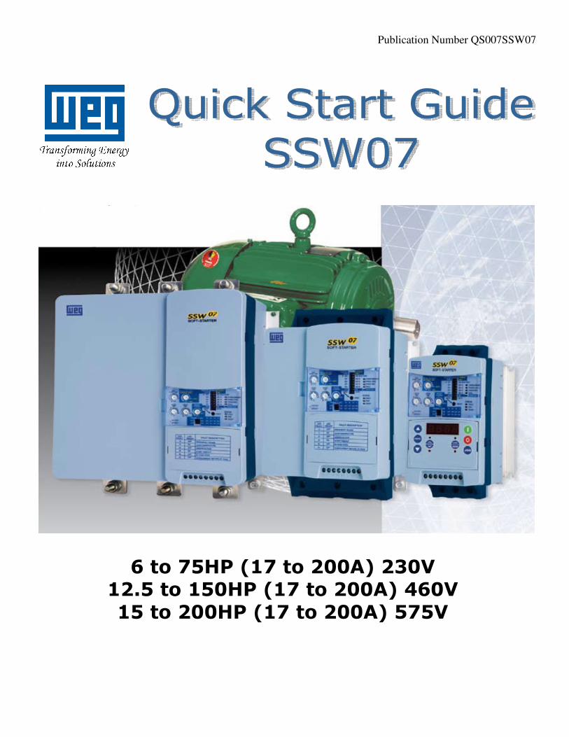
Power Connections: The SSW07 Quick Start Guide is a supplement to help get the SSW07 started quickly using the most common installation and configuration options. This SSW07 Quick Start Guide is not meant to replace the SSW07 User’s Manual. For detailed instructions, safety precautions, proper mounting, installation, configuration, and operation please refer to the SSW07 User’s Guide. Warning: Only qualified personnel should plan or implement the installation, start-up, operation and maintenance of this equipment. Personnel must read the entire SSW07 User’s Guide before attempting to install, operate or troubleshoot the SSW07.
Figure 1 - Power and Grounding Connections Basic Wiring:
1. Mount the SSW07 to a flat vertical surface. 2. Connect the three-phase incoming power leads to the R, S, and T connections on the power terminal (refer to
Figure 1). Connect the motor leads to the U, V, and W connections on the power terminal and connect the GROUND lead to PE on the chassis (refer to Figure 1). Note: Only three-phase AC motors can be used.
3. Connect the control power line (L) and neutral (N) leads to the A1 and A2 connectors (refer to Figure 1).
Control Power
L N
3
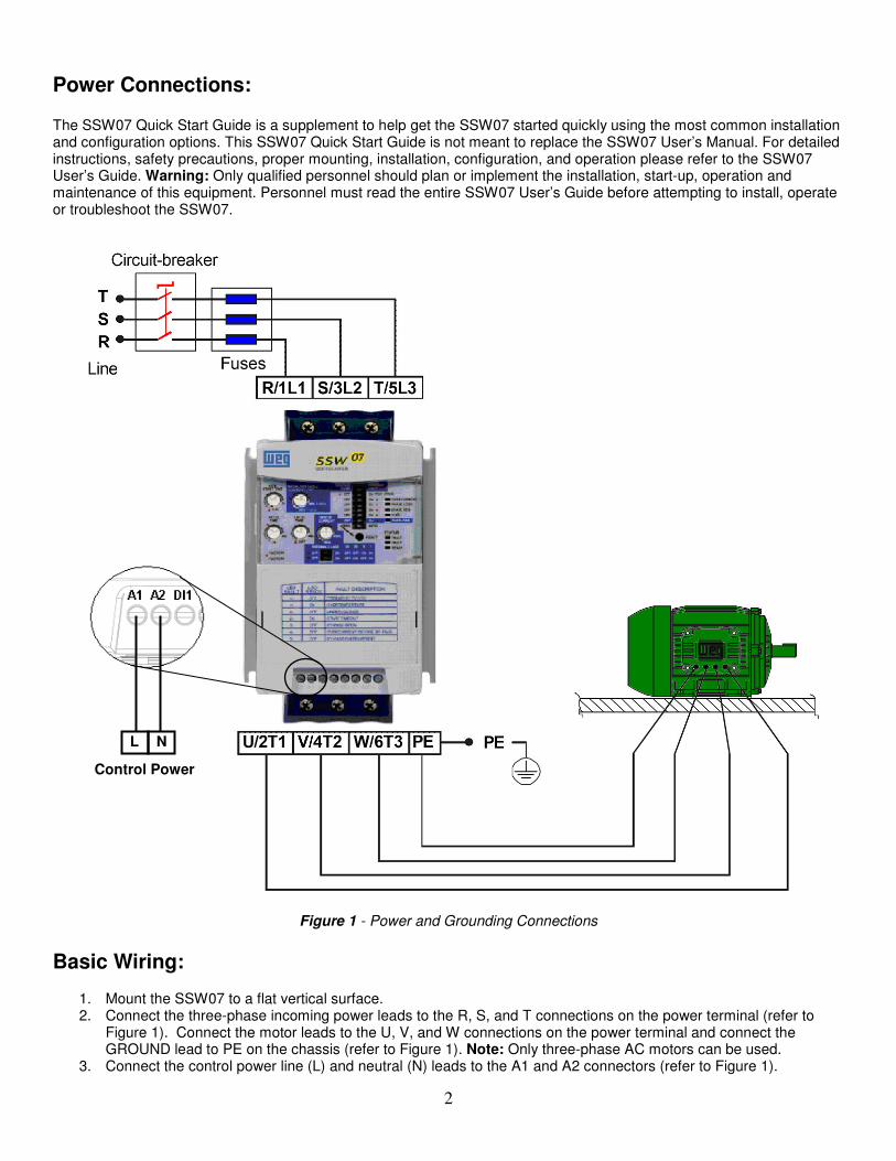
USING HMI (OPTIONAL)

4
Start-up by Voltage Ramp: (most common configuration)
1. The soft starter should be powered up with a display of “RDY”.
2. Press the key to enter the programming mode.
3. Press the or key to select P000.
4. Press the key to change value of parameter.
5. Press the or key to set to “5” to allow access to parameters.
6. Press the key to save the selected option.
7. Press the or key to select P219.
8. Press the key to change value of parameter.
9. Press the or key to set to “0” for keypad programming.
10. Press the to save the selected option.
11. Press the or key to select P202.
12. Press the key to change value of parameter.
13. Press the or key to set to “0” for Voltage Ramp.
14. Press the key to save the selected option and exit the programming mode.
15. Press the or key to select P003 (Motor Current).
16. Press the key to read the Motor Current value (This is a read parameter).
17. Press the key to operate soft-start via HMI.
18. Press the start key. The motor accelerates to full voltage and the bypass contact engages.
Note: If the direction of rotation is not correct, switch off the soft starter and swap any two wires at the motor
output.
19. Press the stop key. The motor decelerates until stopping by coast to rest. Time to stop depends on load
inertia and friction.
Note: For a complete description of Parameters and Error codes refer to Chapters 6 and 7 in the SSW07
Programming Manual.
5
Local/Remote Modes (Optional HMI):
In the previous section the soft starter was operated from the keypad (Local Mode). Note the green local indicator LED on
the bottom right of the keypad. For the factory default programming, the selection of the operation mode (Local/Remote)
is made via the “Local/Remote” key (default is Remote). Pressing of the “Local/Remote” will alternate operation between
local & remote. Notice the indicator switches from the green to the red indicator LED when “Local/Remote” is pressed.
If you wish to use an external Local/Remote switch set P220=4, connect the switch to one of the Digital Inputs (DI1-DI3),
and set the corresponding parameter (P263 to 265=2).
To always run in Local mode set P220=0.
To always run in Remote mode set P220=1.
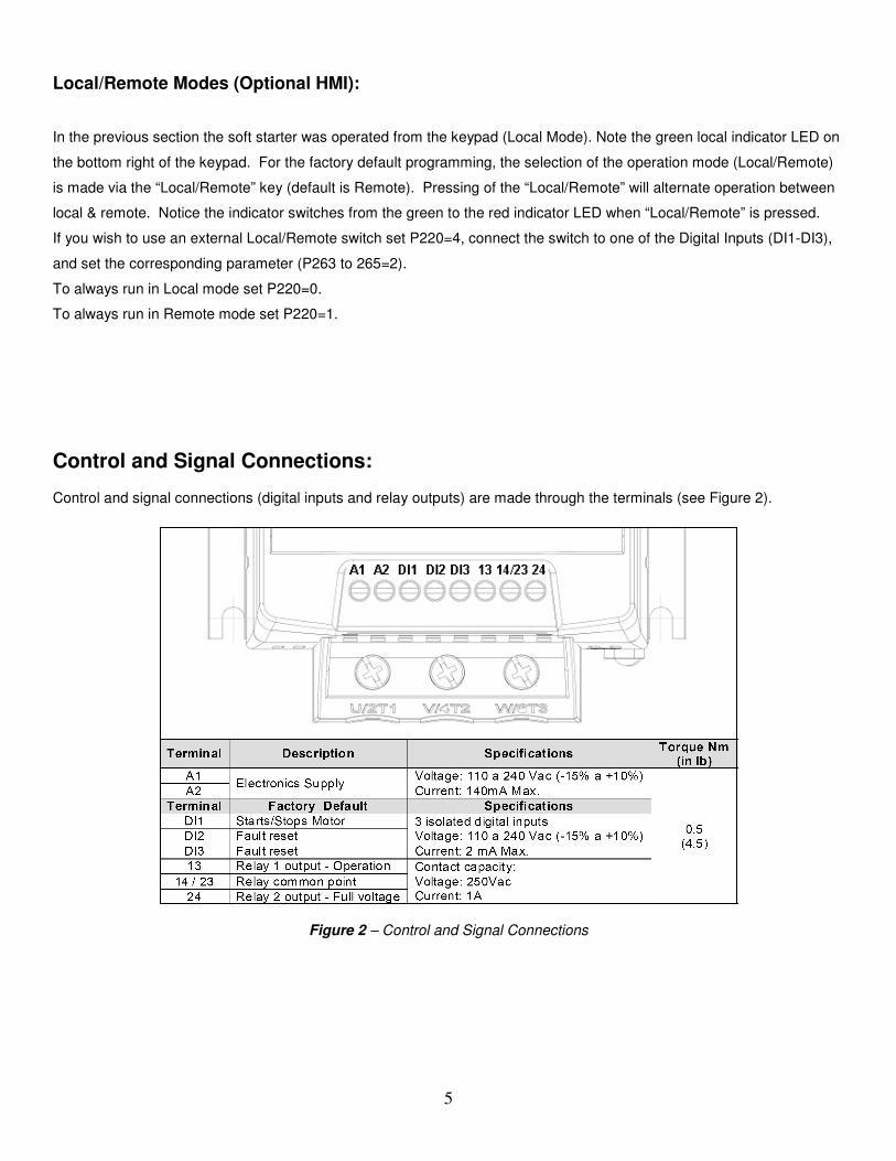
Control and Signal Connections:
Control and signal connections (digital inputs and relay outputs) are made through the terminals (see Figure 2).
Figure 2 – Control and Signal Connections

6
Control via 2-Wire Start/Stop (Remote Mode):
Figure 3 – Control via 2-Wire Start/Stop
Control Wiring: Start/Stop switch is N.O. (normally open) and is wired as shown in Figure 3. Parameters (Optional HMI):
1. Set P220 = 1 Always Remote 2. Set P230 = 1 Digital Inputs 3. Set P263 = 1 DI1 Enable/Disable
Control via 3-Wire Start/Stop (Remote Mode):
Terminal A1 A2 DI1 DI2 DI3 13
14/23 24
Figure 4 – Control via 3-Wire Start/Stop
Control Wiring: “Start” and “Stop” are momentary push button switches and are connected as shown in Figure 4. “Start” is a N.O. (normally open) contact and “Stop” is a N.C. (normally closed) contact.
Terminal A1 A2 DI1 DI2 DI3 13
14/23 24
Start/Stop
Line Neutral
Control Power
Start
Stop
Note: DI2 will need to be programmed for 3-Wire control.
Line Neutral
Control Power
7
Parameters (Optional HMI):
1. Set P220 = 1 Always Remote
2. Set P230 = 1 Digital Inputs
3. Set P263 = 1 DI1 Start (three wires)
4. Set P264 = 1 DI2 Stop (three wires)
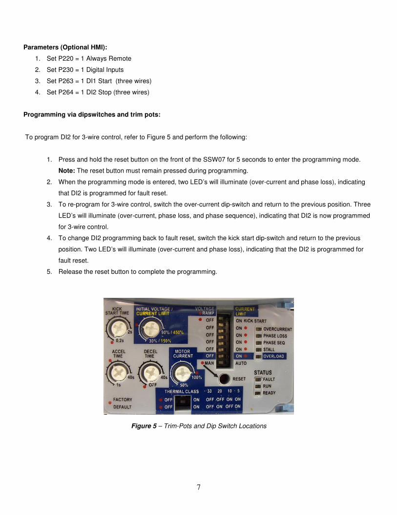
Programming via dipswitches and trim pots:
To program DI2 for 3-wire control, refer to Figure 5 and perform the following:
1. Press and hold the reset button on the front of the SSW07 for 5 seconds to enter the programming mode.
Note: The reset button must remain pressed during programming.
2. When the programming mode is entered, two LED’s will illuminate (over-current and phase loss), indicating
that DI2 is programmed for fault reset.
3. To re-program for 3-wire control, switch the over-current dip-switch and return to the previous position. Three
LED’s will illuminate (over-current, phase loss, and phase sequence), indicating that DI2 is now programmed
for 3-wire control.
4. To change DI2 programming back to fault reset, switch the kick start dip-switch and return to the previous
position. Two LED’s will illuminate (over-current and phase loss), indicating that the DI2 is programmed for
fault reset.
5. Release the reset button to complete the programming.
Figure 5 – Trim-Pots and Dip Switch Locations
8
Parameters Example (Optional HMI) (P219 = 1): Soft Starter Data (Example) Model: EXSSW070130T5SZ
Motor Data (Example) Power: 75 HP Rated Speed: 1770 RPM Rated Current: 101A Rated Voltage: 380 V Service Factor: 1.15
• The following is a typical list of parameter changes needed using the Motor/Soft Starter data shown above.
P000=5 Parameter Access (5 = Password)
P219=1 Parameterization via keypad/ (trim pots and DIP switches) (1 = keypad)
P202=0 Type of Control (0 = Voltage Ramp)
P101=35 Initial Selected Voltage (35%)
P102=15 Voltage Ramp Time (15 seconds)
P400=380 Motor Rated Voltage (380 volts)
P401=77.7% Motor Rated Current (101 amps)
P406=1.15 Motor Service Factor (1.15)
P640=6 Thermal Motor Protection Class (Class 30)
• Local/Remote parameters allow the soft starter to be set up to operate from Keypad, Remote Terminal, or a
programmed combination of keypad and terminal inputs.
P220 – Local/Remote Selection
P229 – Local Status Command
P230 – Remote Status Command
• Read Only Parameters (P001 – P081) can be used for monitoring and troubleshooting. For a full list and
description please read the SSW07 Programming Manual. By monitoring certain read only parameters, the status
of inputs, outputs, and soft starter operational values can be determined without the use of any other test
equipment.
P003 - Motor Current
P006 - Soft Starter Status
P007 - Output Voltage
P012 - Digital Input Status
P013 - (Relay Output Status) – used to monitor relay outputs.
9
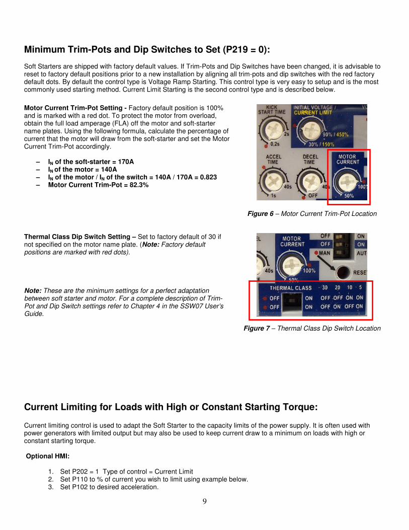
Minimum Trim-Pots and Dip Switches to Set (P219 = 0): Soft Starters are shipped with factory default values. If Trim-Pots and Dip Switches have been changed, it is advisable to reset to factory default positions prior to a new installation by aligning all trim-pots and dip switches with the red factory default dots. By default the control type is Voltage Ramp Starting. This control type is very easy to setup and is the most commonly used starting method. Current Limit Starting is the second control type and is described below. Motor Current Trim-Pot Setting - Factory default position is 100% and is marked with a red dot. To protect the motor from overload, obtain the full load amperage (FLA) off the motor and soft-starter name plates. Using the following formula, calculate the percentage of current that the motor will draw from the soft-starter and set the Motor Current Trim-Pot accordingly.
– IN of the soft-starter = 170A – IN of the motor = 140A – IN of the motor / IN of the switch = 140A / 170A = 0.823 – Motor Current Trim-Pot = 82.3%
Figure 6 – Motor Current Trim-Pot Location
Thermal Class Dip Switch Setting – Set to factory default of 30 if not specified on the motor name plate. (Note: Factory default positions are marked with red dots). Note: These are the minimum settings for a perfect adaptation between soft starter and motor. For a complete description of Trim-Pot and Dip Switch settings refer to Chapter 4 in the SSW07 User’s Guide.
Figure 7 – Thermal Class Dip Switch Location
Current Limiting for Loads with High or Constant Starting Torque: Current limiting control is used to adapt the Soft Starter to the capacity limits of the power supply. It is often used with power generators with limited output but may also be used to keep current draw to a minimum on loads with high or constant starting torque. Optional HMI:
1. Set P202 = 1 Type of control = Current Limit 2. Set P110 to % of current you wish to limit using example below. 3. Set P102 to desired acceleration.
10
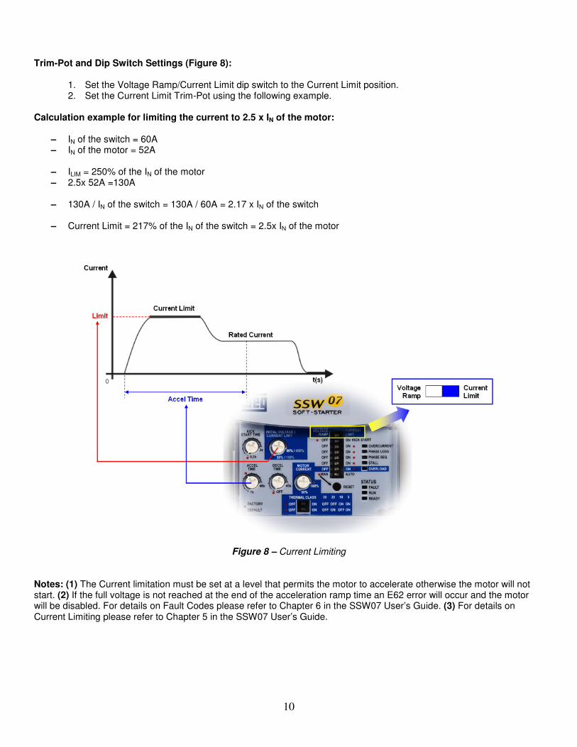
Trim-Pot and Dip Switch Settings (Figure 8):
1. Set the Voltage Ramp/Current Limit dip switch to the Current Limit position. 2. Set the Current Limit Trim-Pot using the following example.
Calculation example for limiting the current to 2.5 x IN of the motor:
– IN of the switch = 60A – IN of the motor = 52A
– ILIM = 250% of the IN of the motor – 2.5x 52A =130A
– 130A / IN of the switch = 130A / 60A = 2.17 x IN of the switch
– Current Limit = 217% of the IN of the switch = 2.5x IN of the motor
Figure 8 – Current Limiting
Notes: (1) The Current limitation must be set at a level that permits the motor to accelerate otherwise the motor will not start. (2) If the full voltage is not reached at the end of the acceleration ramp time an E62 error will occur and the motor will be disabled. For details on Fault Codes please refer to Chapter 6 in the SSW07 User’s Guide. (3) For details on Current Limiting please refer to Chapter 5 in the SSW07 User’s Guide.

11
Soft Starter Operation: The Soft Starter is now ready to operate via the 2-Wire or 3-Wire Control that was set up in the previous steps. To start the motor, press the “Start Button” and the Soft Starter will accelerate up to speed (default acceleration time is 20sec). When full voltage is reached the internal bypass contactors will engage and switch the motor to the supply line. To stop the motor, press the “Stop Button” and the Soft Starter will decelerate to the stop position (default deceleration time is “Off” so the motor will coast to rest). For details on setting deceleration time and other trim-pots refer to Chapter 4 in the SSW07 User’s Guide. Fault Codes: Optional HMI: When a fault is detected, the soft starter is disabled and the Fault Code is displayed (example E03). To restart the soft starter after a fault has occurred, the soft starter must be reset. Resetting the soft starter can be done by disconnecting and reapplying AC power (power-off reset), by pressing the “O/RESET” key (manual reset), automatic reset, or via digital inputs. For details on Reset and a full list and description of Fault Codes, please read Chapter 6 in the SSW07 User’s Guide. Trim-pots and DIP switches: When a fault is detected, the soft starter is disabled and the Fault Code is displayed by flashing LED’s. To restart the soft starter after a fault has occurred, the soft starter must be reset. Resetting the soft starter can be done by disconnecting and reapplying AC power (power-on reset), by pressing the “RESET” button on the front panel (manual reset), automatic reset, or via digital inputs. For details on Reset and a full list and description of Fault Codes please read Chapter 6 in the SSW07 User’s Guide.