Embed Size (px)
Citation preview
Soft-Starter
Arrancador Suave
Soft-Starter
Sanftanlaufgerät
Устройство плавного пуска
SSW-06
Motors | Automation | Energy | Transmission & Distribution | Coatings
User's ManualManual del UsuarioManual do UsuárioBedienungsanleitung Руководство пользователя
ATTENTION!
It is very important to check if the
Soft-Starter Software is the same as
mentioned above.
08/2015
Series: SSW-06
Software: version 1.8X
Language: English
Document: 0899.5854 /17
SOFT-STARTER
MANUAL
Summary of Revisions
The table below describes the revisions made to this manual.
Revision Description Section
1 First edition -
2 General revision -
3 General revision -
4 New software version -
5 Implementation of the following current: 412A, Chap 3
480A, 604A, 670A, 820A, 950A, 1100A and 1400A. and 10
New software version with: braking methods 3, 4, 6
FWD/REV and Jog. and 8
P140 was changed. E73 was eliminated.
E71 and E77 were changed.
6 General revision -
7 New software version with: new states in P006, Chap 4,
full voltage and starting diagnostic functions, 6 and 8
storage of the 6 last errors, consumed energy,
torque and power protections, motor thermal
protection alarm, selection between alarm or fault,
automatic detection of the acceleration end with
voltage ramp, fast visualization of the parameters
through the key, detection of the
Profibus DP master in Stop, and the PLC Software,
inclusion of the E11, E18, E57, E58 and E59.
8 Change of the table 3.1 and figures 10.1, 10.3, Chap 3 and
10.4, 10.5, 10.6 and 10.7. 10
9 Implementation of the following current: -
10A, 16A, 23A, 30A, 45A e 60A.
11 New line voltage of 690V for standard motor -
connection.
12 New software version with: digital inputs -
DI1, DI2 and DI3 programmable for the
same functions, new current models of
1000A and 1300A in P295, new option of
Fatal Fault for P313, disable of the E77 Fault
through the P621 for use in multimotor
applications, new MMC block for SoftPLC,
new P951 parameter for enable of the IOs
expansion card for SoftPLC, new
emergency start through digital input.
New optional kits KFB-DNIP, K-USB, K-IOE and K-ECA.
13 New optional kit, K-PT100. 6, 8 and 9
New parameters for optional kit K-PT100
(P091 to P095, P670 to P691).
New faults and alarms for optional
kit K-PT100 (E33 to E37, E39, E43 to E52).
14 Revision in table 3.9. 3
15 General revision 1
16 and 17 New software version: short circuit protection -
function in the power of the SSW-06 with the motor
stopped (P622 and E19), new programming options
for digital outputs (grouping of protections).
Summary
Quick Parameter Reference, Fault and Status Messages
I Parameters .......................................................................................... 09II Fault or Alarm Messages .................................................................... 21III Other Messages ................................................................................ 21
CHAPTER 1Safety Notices
1.1 Safety Notices in the Manual ............................................................ 221.2 Safety Notices on the Product .......................................................... 221.3 Preliminary Recommendations ......................................................... 23
CHAPTER 2General Information
2.1 About this Manual ............................................................................ 242.2 Software Version .............................................................................. 242.3 About the Soft-Starter SSW-06 ......................................................... 242.4 Soft-Starter SSW-06 Identification .................................................... 282.5 Receiving and Storage ...................................................................... 30
CHAPTER 3Installation and Connection
3.1 Mechanical Installation ..................................................................... 313.1.1 Environment Conditions .............................................................. 313.1.2 Dimensions of the Soft-Starter SSW-06 ...................................... 313.1.3 Positioning / Fixing..................................................................... 32
3.1.3.1 Mounting inside a Panel .................................................... 333.1.3.2 Mounting on a Surface ...................................................... 36
3.2 Electrical Installation ........................................................................ 373.2.1 Power Terminals ......................................................................... 383.2.2 Location of the Power/ Grounding, Control Connections and
Fan Voltage Selection ................................................................. 433.2.3 Recommended Power/Grounding Cables .................................... 443.2.4 Connection of the Power Supply to the Soft-Starter ..................... 47
3.2.4.1 Short Circuit Current Capacity of the Power Supply ........... 473.2.4.2 Recommended Fuses ....................................................... 48
3.2.5 Connection of the SSW-06 Soft-Starter to the motor ................... 493.2.5.1 Standard Three-Wire Connection (P150=0=Inactive) .......... 493.2.5.2 Inside Delta Motor Connection (P150=1=Active) ................ 50
3.2.6 Grounding Connections .............................................................. 513.2.7 Fan Connections ........................................................................ 523.2.8 Signal and Control Connections.................................................. 533.2.9 RS-232, X2 Serial Communication Connection ........................... 563.2.10 XC8 Serial Communication Board Connection .......................... 563.2.11 XC6 Fieldbus Communication Board Connection ...................... 56
Summary
3.3 Recommended Set-Ups ................................................................... 563.3.1 Recommended Set-ups using Keypad Command
with Isolating Contactor. ............................................................. 583.3.2 Recommended Set-ups using Keypad Command
with Circuit-breaker .................................................................... 583.3.3 Recommended Set-ups with Command via Two-wire
Digital Inputs .............................................................................. 593.3.4 Recommended Set-ups with Command via Three-wire
Digital Inputs .............................................................................. 593.3.5 Recommended Set-ups with Command via Three-wire
Digital Input and Inside Delta Motor Connection. ........................ 603.3.6 Recommended Set-ups with Command via Three-wire
Digital Input or Serial Communication. ....................................... 603.3.7 Recommended Set-ups with Command via Three-wire
Digital Input or Fieldbus Communication. ................................... 613.3.8 Recommended Setup with Command via Digital Inputs
and direction of rotation............................................................. 613.3.9 Recommended Setup with Command via Digital Inputs
and Reverse Braking .................................................................. 623.3.10 Recommended Setup with Command via Digital Inputs
and Optimal Braking ................................................................ 623.3.11 Recommended Setup with Command via Digital Inputs
and DC-Braking ........................................................................ 633.3.12 Recommended Setup with Command via Digital Inputs
and External By-pass Contactor .............................................. 633.3.13 Symbols ................................................................................... 64
3.4 European Directives for Electromagnetic Compatibility Requirements for Installation ......................................................... 653.4.1 Installation .................................................................................. 65
CHAPTER 4Keypad Operation
4.1 Description of the Keypad (HMI-SSW-06) ......................................... 664.2 Use of the Keypad ............................................................................ 68
4.2.1 Keypad use for Soft-Starter SSW-06 Operation .......................... 684.2.2 Keypad Display - Signalling Indications ...................................... 694.2.3 Parameter viewing and programming .......................................... 70
CHAPTER 5Start-up
5.1 Power-up Preparation .......................................................................735.2 Initial Power-up (required parameter settings) ...................................745.3 Start-up ............................................................................................81
5.3.1 Start-up: Operation via Keypad Type of Control: Voltage Ramp ...81
Summary
CHAPTER 6Detailed Parameter Description
6.1 Access and Read Only Parameters - P000 to P099 .........................846.2 Regulation Parameters - P100 to P199.............................................946.3 Configuration Parameters - P200 to P299 .........................................1036.4 Serial Communication Parameters - P300 to P399 ...........................1166.5 Motor Parameters - P400 to P499 ....................................................1186.6 Special Function Parameters - P500 to P599 ...................................1196.7 Protection Parameters - P600 to P699 .............................................1256.8 Selection Between Fault and Alarm - P700 to P790 .........................1376.9 SoftPLC Parameters - P950 to P999 ................................................139
CHAPTER 7Programming Information and Suggestions
7.1 Applications and Programming .........................................................1407.1.1 Starting by Voltage Ramp (P202=0) ............................................1427.1.2 Starting by Current Limit (P202=1) .............................................1437.1.3 Starting by Current Ramp with High Initial Current (P202=4) .......1447.1.4 Starting by Current Ramp with Low Initial Current (P202=4) ........1457.1.5 Starting with Pump Control (P202=2) ..........................................1467.1.6 Starting with Torque Control (P202=3) .........................................148
7.1.6.1 Loads with Constant Torque (P202=3 and P120=1 point) ....1497.1.6.2 Loads with Higher Initial Torque
(P202=3 and P120=3 points) .............................................1497.1.6.3 Loads with Constant Torque and S Speed Curve
(P202=3 and 120=3 points) ...............................................1507.1.6.4 Loads with Quadratic Torque and S Speed Curve
(P202=3 and P120=2 points) ..............................................1507.1.6.5 Loads with Quadratic Torque and Linear Speed Curve
(P202=3 and P120=3 points) .............................................1517.1.6.6 Loads with Quadratic Torque and Higher Initial Torque
(P202=3 and P120=3 points) ..............................................1517.1.6.7 Hydraulic Pump Load Type (P202=3) .................................152
7.2 Protections and Programming ..........................................................1557.2.1 Thermal Classes ........................................................................155
7.2.1.1 Suggestions on How to Set Thermal Class .........................1557.2.1.2 Example on How to Set the Thermal Class ........................1567.2.1.3 Time Reduction When Changing from Cold Starting to
Hot Starting .......................................................................1577.2.1.4 Service Factor ....................................................................157
7.2.2 Under- and Over- Protections......................................................1587.2.2.1 Undervoltage and Overvoltage protection .............................1587.2.2.2 Underload Protection ..........................................................1587.2.2.3 Overload Protection ............................................................158
Summary
CHAPTER 8Diagnostics and Troubleshooting
8.1 Faults and Possible Causes .............................................................1608.2 Troubleshooting ................................................................................1668.3 Technical Assistance Contacting ......................................................1668.4 Preventive Maintenance ....................................................................167
8.4.1 Cleaning Instructions ..................................................................1688.5 Spare Part List .................................................................................169
CHAPTER 9Options and Accessories
9.1 Remote Keypad and Cables .............................................................1719.2 RS-485 for the Soft-Starter SSW-06 .................................................173
9.2.1 RS-485 Communication Kit (KRS-485) .......................................1739.2.2 Optional Module MIW-02 ............................................................174
9.3 Fieldbus Communication Kits ...........................................................1749.3.1 Fieldbus DeviceNet Communication Kit (KFB-DN) ....................1749.3.2 Fieldbus Profibus DP Communication Kit (KFB-DP) .................1759.3.3 Fieldbus Profibus DP-V1 Communication Kit (KFB-PDPV1) ......1759.3.4 Fieldbus DeviceNet Drive Profile Communication Kit (KFB-DD) .1759.3.5 Fieldbus EtherNet/IP or Modbus/TCP Communication Kit
(KFB-ENIP) ..............................................................................1769.4 USB .................................................................................................176
9.4.1 USB Communication Kit (K-USB) ..............................................1769.5 Inputs and Outputs Expansion Board ...............................................176 9.5.1 Digital Inputs and Outputs Expansion Kit (K-IOE) ....................177 9.5.2 PT100 inputs Kit (K-PT100) ......................................................1779.6 External Current Acquisition .............................................................178
9.6.1 External Current Acquisition Kit (K-ECA) ...................................178
CHAPTER 10Technical Specifications
10.1 Currents and Ratings According to UL508 ......................................17910.2 Currents and Ratings for IP55, IV Pole Weg Motor .........................18110.3 Power Data ....................................................................................18310.4 Electronics/Programming Data .......................................................18310.5 Mechanical Data ............................................................................185
9
SSW-06 - QUICK PARAMETER REFERENCE
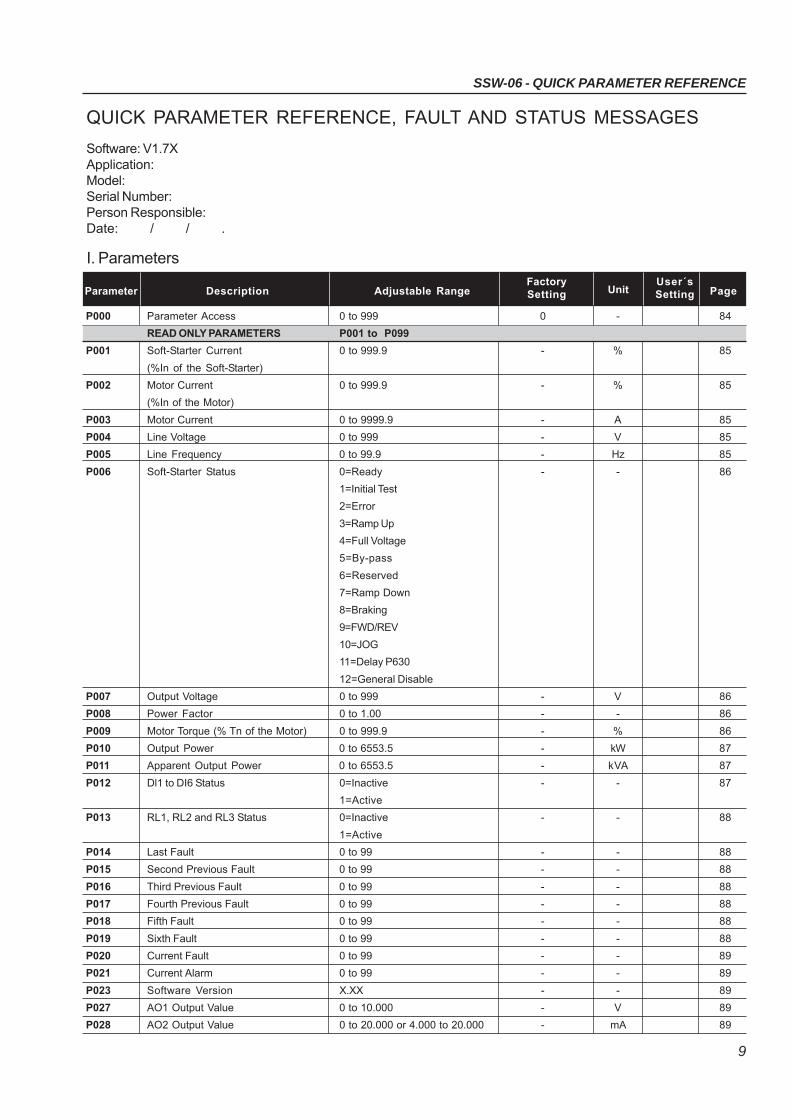
QUICK PARAMETER REFERENCE, FAULT AND STATUS MESSAGES
Software: V1.7XApplication:Model:Serial Number:Person Responsible:Date: / / .
I. Parameters
Parameter Description Adjustable RangeFactory
UnitUser´s
PageSetting Setting
P000 Parameter Access 0 to 999 0 - 84
READ ONLY PARAMETERS P001 to P099
P001 Soft-Starter Current 0 to 999.9 - % 85
(%In of the Soft-Starter)
P002 Motor Current 0 to 999.9 - % 85
(%In of the Motor)
P003 Motor Current 0 to 9999.9 - A 85
P004 Line Voltage 0 to 999 - V 85
P005 Line Frequency 0 to 99.9 - Hz 85
P006 Soft-Starter Status 0=Ready - - 86
1=Initial Test
2=Error
3=Ramp Up
4=Full Voltage
5=By-pass
6=Reserved
7=Ramp Down
8=Braking
9=FWD/REV
10=JOG
11=Delay P630
12=General Disable
P007 Output Voltage 0 to 999 - V 86
P008 Power Factor 0 to 1.00 - - 86
P009 Motor Torque (% Tn of the Motor) 0 to 999.9 - % 86
P010 Output Power 0 to 6553.5 - kW 87
P011 Apparent Output Power 0 to 6553.5 - kVA 87
P012 Dl1 to DI6 Status 0=Inactive - - 87
1=Active
P013 RL1, RL2 and RL3 Status 0=Inactive - - 88
1=Active
P014 Last Fault 0 to 99 - - 88
P015 Second Previous Fault 0 to 99 - - 88
P016 Third Previous Fault 0 to 99 - - 88
P017 Fourth Previous Fault 0 to 99 - - 88
P018 Fifth Fault 0 to 99 - - 88
P019 Sixth Fault 0 to 99 - - 88
P020 Current Fault 0 to 99 - - 89
P021 Current Alarm 0 to 99 - - 89
P023 Software Version X.XX - - 89
P027 AO1 Output Value 0 to 10.000 - V 89
P028 AO2 Output Value 0 to 20.000 or 4.000 to 20.000 - mA 89
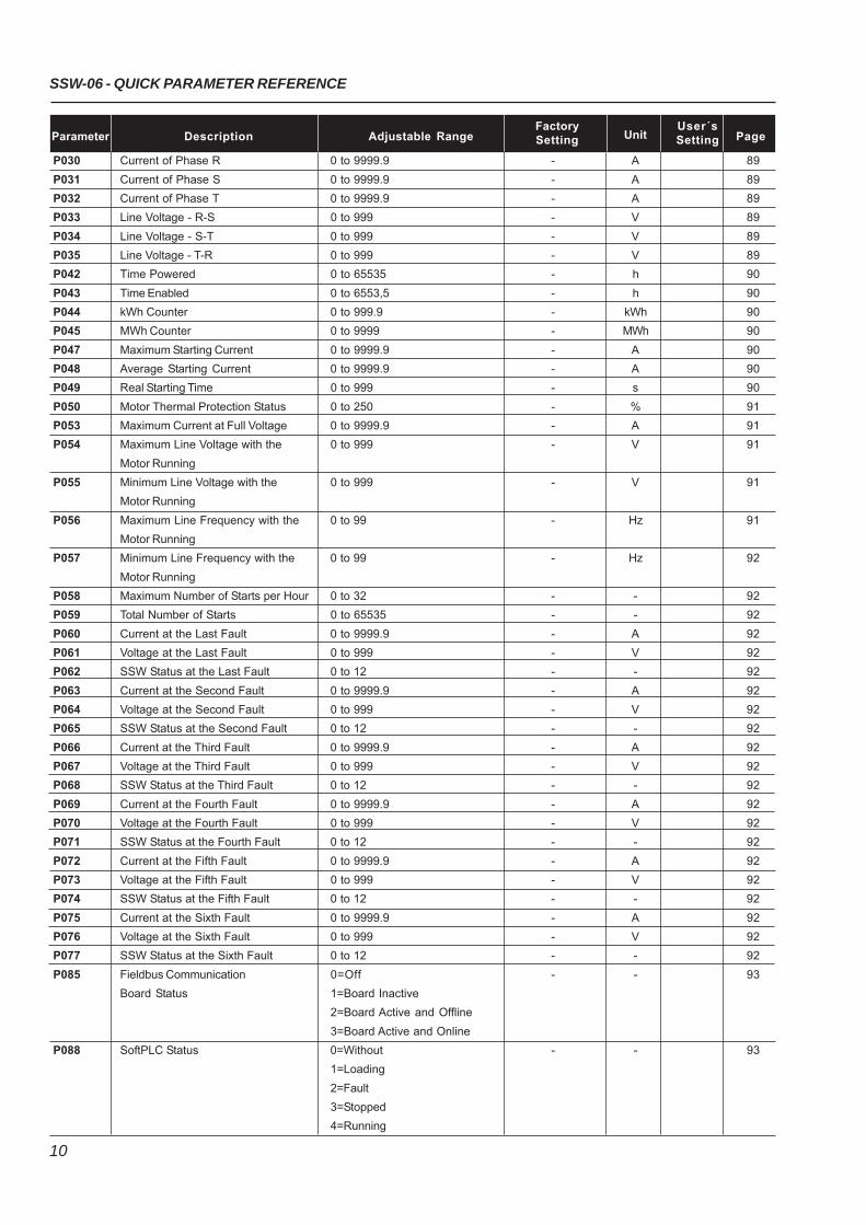
SSW-06 - QUICK PARAMETER REFERENCE
10
Parameter Description Adjustable RangeFactory
UnitUser´s
PageSetting Setting
P030 Current of Phase R 0 to 9999.9 - A 89
P031 Current of Phase S 0 to 9999.9 - A 89
P032 Current of Phase T 0 to 9999.9 - A 89
P033 Line Voltage - R-S 0 to 999 - V 89
P034 Line Voltage - S-T 0 to 999 - V 89
P035 Line Voltage - T-R 0 to 999 - V 89
P042 Time Powered 0 to 65535 - h 90
P043 Time Enabled 0 to 6553,5 - h 90
P044 kWh Counter 0 to 999.9 - kWh 90
P045 MWh Counter 0 to 9999 - MWh 90
P047 Maximum Starting Current 0 to 9999.9 - A 90
P048 Average Starting Current 0 to 9999.9 - A 90
P049 Real Starting Time 0 to 999 - s 90
P050 Motor Thermal Protection Status 0 to 250 - % 91
P053 Maximum Current at Full Voltage 0 to 9999.9 - A 91
P054 Maximum Line Voltage with the 0 to 999 - V 91
Motor Running
P055 Minimum Line Voltage with the 0 to 999 - V 91
Motor Running
P056 Maximum Line Frequency with the 0 to 99 - Hz 91
Motor Running
P057 Minimum Line Frequency with the 0 to 99 - Hz 92
Motor Running
P058 Maximum Number of Starts per Hour 0 to 32 - - 92
P059 Total Number of Starts 0 to 65535 - - 92
P060 Current at the Last Fault 0 to 9999.9 - A 92
P061 Voltage at the Last Fault 0 to 999 - V 92
P062 SSW Status at the Last Fault 0 to 12 - - 92
P063 Current at the Second Fault 0 to 9999.9 - A 92
P064 Voltage at the Second Fault 0 to 999 - V 92
P065 SSW Status at the Second Fault 0 to 12 - - 92
P066 Current at the Third Fault 0 to 9999.9 - A 92
P067 Voltage at the Third Fault 0 to 999 - V 92
P068 SSW Status at the Third Fault 0 to 12 - - 92
P069 Current at the Fourth Fault 0 to 9999.9 - A 92
P070 Voltage at the Fourth Fault 0 to 999 - V 92
P071 SSW Status at the Fourth Fault 0 to 12 - - 92
P072 Current at the Fifth Fault 0 to 9999.9 - A 92
P073 Voltage at the Fifth Fault 0 to 999 - V 92
P074 SSW Status at the Fifth Fault 0 to 12 - - 92
P075 Current at the Sixth Fault 0 to 9999.9 - A 92
P076 Voltage at the Sixth Fault 0 to 999 - V 92
P077 SSW Status at the Sixth Fault 0 to 12 - - 92
P085 Fieldbus Communication 0=Off - - 93
Board Status 1=Board Inactive
2=Board Active and Offline
3=Board Active and Online
P088 SoftPLC Status 0=Without - - 93
1=Loading
2=Fault
3=Stopped
4=Running
11
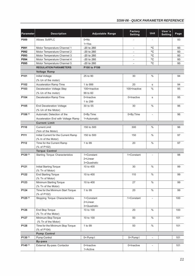
SSW-06 - QUICK PARAMETER REFERENCE
Parameter Description Adjustable RangeFactory
UnitUser´s
PageSetting Setting
P089 Allows SoftPLC 0=No - - 93
1=Yes
P091 Motor Temperature Channel 1 -20 to 260 - ºC 93
P092 Motor Temperature Channel 2 -20 to 260 - ºC 93
P093 Motor Temperature Channel 3 -20 to 260 - ºC 93
P094 Motor Temperature Channel 4 -20 to 260 - ºC 93
P095 Motor Temperature Channel 5 -20 to 260 - ºC 93
REGULATION PARAMETERS P100 to P199
Voltage Ramp
P101 Initial Voltage 25 to 90 30 % 94
(% Un of the motor)
P102 Acceleration Ramp Time 1 to 999 20 s 94
P103 Deceleration Voltage Step 100=Inactive 100=Inactive % 95
(% Un of the motor) 99 to 60
P104 Deceleration Ramp Time 0=Inactive 0=Inactive s 95
1 to 299
P105 End Deceleration Voltage 30 to 55 30 % 96
(% Un of the Motor)
P106 (1) Automatic Detection of the 0=By Time 0=By Time - 96
Acceleration End with Voltage Ramp 1=Automatic
Current Limit
P110 Current Limit 150 to 500 300 % 96
(%In of the Motor)
P111 Initial Current for the Current Ramp 150 to 500 150 % 97
(% In of the Motor)
P112 Time for the Current Ramp 1 to 99 20 % 97
(% of P102)
Torque Control
P120 (1) Starting Torque Characteristics 1=Constant 1=Constant - 98
2=Linear
3=Quadratic
P121 Initial Starting Torque 10 to 400 30 % 99
(% Tn of Motor)
P122 End Starting Torque 10 to 400 110 % 99
(% Tn of Motor)
P123 Minimum Starting Torque 10 to 400 27 % 99
(% Tn of the Motor)
P124 Time for the Minimum Start Torque 1 to 99 20 % 99
(% of P102)
P125 (1) Stopping Torque Characteristics 1=Constant 1=Constant - 100
2=Linear
3=Quadratic
P126 End Stop Torque 10 to 100 20 % 100
(% Tn of the Motor)
P127 Minimum Stop Torque 10 to 100 50 % 101
(% Tn of the Motor)
P128 Time for the Minimum Stop Torque 1 to 99 50 % 101
(% of P104)
Pump Control
P130 (1) Pump Control 0= Pump I 0= Pump I - 101
By-pass
P140 (1) External By-pass Contactor 0=Inactive 0=Inactive - 101
1=Active
SSW-06 - QUICK PARAMETER REFERENCE
12
Parameter Description Adjustable RangeFactory
UnitUser´s
PageSetting Setting
Inside Delta
P150 (1)(2) Inside Delta Motor Connection 0=Inactive 0=Inactive - 102
1=Active
CONFIGURATION PARAMETERS P200 to P399
P200 Password 0=Inactive 1=Active - 103
1=Active
P201 (2) Language Selection 0=Português To be defined - 103
1=English by the user
2=Español
3=Deutsch
P202 (1) Type of Control 0=Voltage Ramp 0=Voltage Ramp - 103
1=Current Limit
2=Pump Control
3=Torque Control
4=Current Ramp
P204 (1) Load/Save Parameters 0=Not Used 0=Not Used - 106
1=Not Used
2=Not Used
3=Resets P043 to P050
4=Resets P053 to P058
5=Loads Factory Default
6=Not Used
7=Loads User Default 1
8=Loads User Default 2
9=Not Used
10=Saves User Default 1
11=Saves User Default 2
12= Not Used
13=Erases SoftPLC
14=Erases SoftPLC User
Parameters
15=Reserved
16=Reserved
P205 Display Default Selection 0=P001 2=P003 - 107
1=P002
2=P003
3=P004
4=P005
5=P006
6=P007
7=P008
8=P009
9=P010
P206 Auto-Reset Time 0=Inactive 0=Inactive s 107
1 to 600
P215 (1) Copy Function 0=Inactive 0=Inactive - 108
1=SSW → HMI
2=HMI → SSW
P218 LCD Display Contrast Adjust. 0 to 150 127 - 109
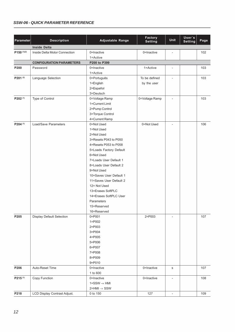
13
SSW-06 - QUICK PARAMETER REFERENCE
Parameter Description Adjustable RangeFactory
UnitUser´s
PageSetting Setting
Local/Remote Definition
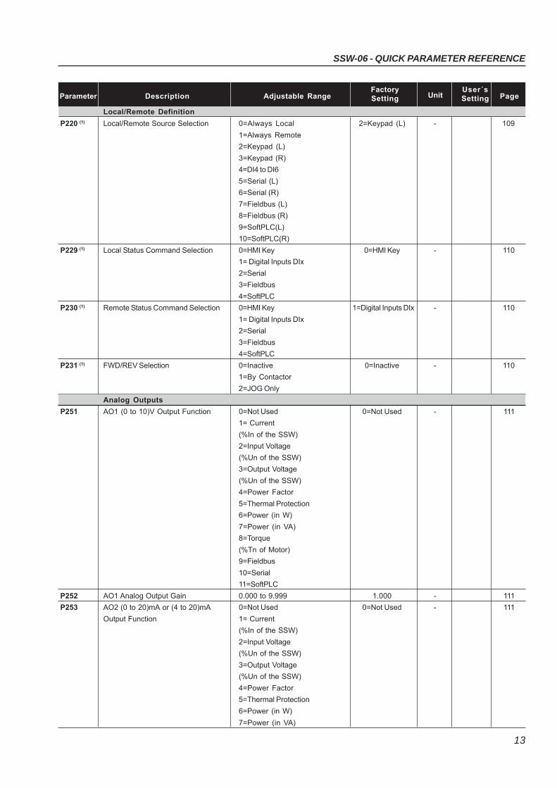
P220 (1) Local/Remote Source Selection 0=Always Local 2=Keypad (L) - 109
1=Always Remote
2=Keypad (L)
3=Keypad (R)
4=DI4 to DI6
5=Serial (L)
6=Serial (R)
7=Fieldbus (L)
8=Fieldbus (R)
9=SoftPLC(L)
10=SoftPLC(R)
P229 (1) Local Status Command Selection 0=HMI Key 0=HMI Key - 110
1= Digital Inputs DIx
2=Serial
3=Fieldbus
4=SoftPLC
P230 (1) Remote Status Command Selection 0=HMI Key 1=Digital Inputs DIx - 110
1= Digital Inputs DIx
2=Serial
3=Fieldbus
4=SoftPLC
P231 (1) FWD/REV Selection 0=Inactive 0=Inactive - 110
1=By Contactor
2=JOG Only
Analog Outputs
P251 AO1 (0 to 10)V Output Function 0=Not Used 0=Not Used - 111
1= Current
(%In of the SSW)
2=Input Voltage
(%Un of the SSW)
3=Output Voltage
(%Un of the SSW)
4=Power Factor
5=Thermal Protection
6=Power (in W)
7=Power (in VA)
8=Torque
(%Tn of Motor)
9=Fieldbus
10=Serial
11=SoftPLC
P252 AO1 Analog Output Gain 0.000 to 9.999 1.000 - 111
P253 AO2 (0 to 20)mA or (4 to 20)mA 0=Not Used 0=Not Used - 111
Output Function 1= Current
(%In of the SSW)
2=Input Voltage
(%Un of the SSW)
3=Output Voltage
(%Un of the SSW)
4=Power Factor
5=Thermal Protection
6=Power (in W)
7=Power (in VA)
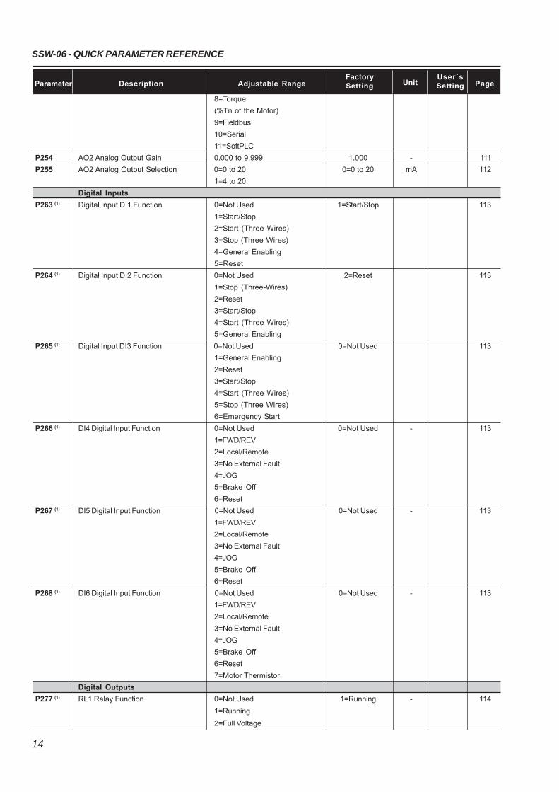
SSW-06 - QUICK PARAMETER REFERENCE
14
Parameter Description Adjustable RangeFactory
UnitUser´s
PageSetting Setting
8=Torque
(%Tn of the Motor)
9=Fieldbus
10=Serial
11=SoftPLC
P254 AO2 Analog Output Gain 0.000 to 9.999 1.000 - 111
P255 AO2 Analog Output Selection 0=0 to 20 0=0 to 20 mA 112
1=4 to 20
Digital Inputs
P263 (1) Digital Input DI1 Function 0=Not Used 1=Start/Stop 113
1=Start/Stop
2=Start (Three Wires)
3=Stop (Three Wires)
4=General Enabling
5=Reset
P264 (1) Digital Input DI2 Function 0=Not Used 2=Reset 113
1=Stop (Three-Wires)
2=Reset
3=Start/Stop
4=Start (Three Wires)
5=General Enabling
P265 (1) Digital Input DI3 Function 0=Not Used 0=Not Used 113
1=General Enabling
2=Reset
3=Start/Stop
4=Start (Three Wires)
5=Stop (Three Wires)
6=Emergency Start
P266 (1) DI4 Digital Input Function 0=Not Used 0=Not Used - 113
1=FWD/REV
2=Local/Remote
3=No External Fault
4=JOG
5=Brake Off
6=Reset
P267 (1) DI5 Digital Input Function 0=Not Used 0=Not Used - 113
1=FWD/REV
2=Local/Remote
3=No External Fault
4=JOG
5=Brake Off
6=Reset
P268 (1) DI6 Digital Input Function 0=Not Used 0=Not Used - 113
1=FWD/REV
2=Local/Remote
3=No External Fault
4=JOG
5=Brake Off
6=Reset
7=Motor Thermistor
Digital Outputs
P277 (1) RL1 Relay Function 0=Not Used 1=Running - 114
1=Running
2=Full Voltage
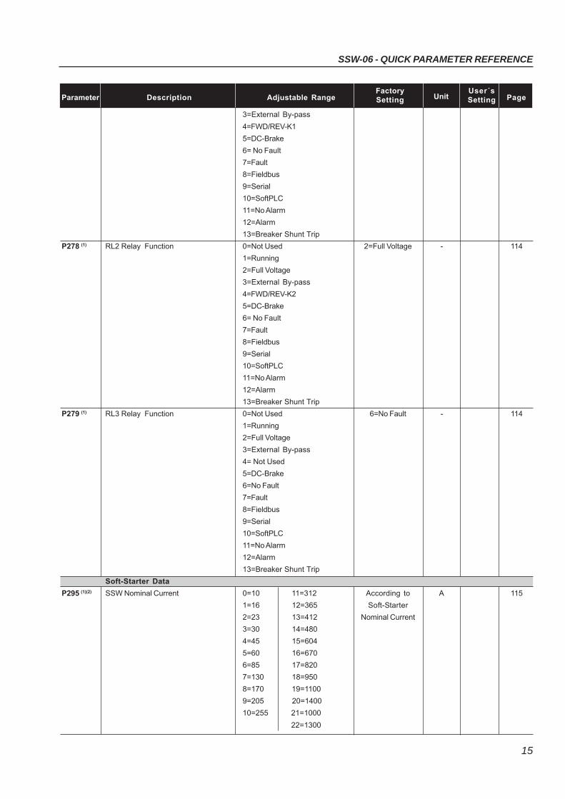
15
SSW-06 - QUICK PARAMETER REFERENCE
Parameter Description Adjustable RangeFactory
UnitUser´s
PageSetting Setting
3=External By-pass
4=FWD/REV-K1
5=DC-Brake
6= No Fault
7=Fault
8=Fieldbus
9=Serial
10=SoftPLC
11=No Alarm
12=Alarm
13=Breaker Shunt Trip
P278 (1) RL2 Relay Function 0=Not Used 2=Full Voltage - 114
1=Running
2=Full Voltage
3=External By-pass
4=FWD/REV-K2
5=DC-Brake
6= No Fault
7=Fault
8=Fieldbus
9=Serial
10=SoftPLC
11=No Alarm
12=Alarm
13=Breaker Shunt Trip
P279 (1) RL3 Relay Function 0=Not Used 6=No Fault - 114
1=Running
2=Full Voltage
3=External By-pass
4= Not Used
5=DC-Brake
6=No Fault
7=Fault
8=Fieldbus
9=Serial
10=SoftPLC
11=No Alarm
12=Alarm
13=Breaker Shunt Trip
Soft-Starter Data
P295 (1)(2) SSW Nominal Current 0=10 11=312 According to A 115
1=16 12=365 Soft-Starter
2=23 13=412 Nominal Current
3=30 14=480
4=45 15=604
5=60 16=670
6=85 17=820
7=130 18=950
8=170 19=1100
9=205 20=1400
10=255 21=1000
22=1300
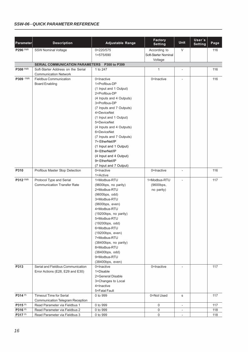
SSW-06 - QUICK PARAMETER REFERENCE
16
Parameter Description Adjustable RangeFactory
UnitUser´s
PageSetting Setting
P296 (1)(2) SSW Nominal Voltage 0=220/575 According to V 116
1=575/690 Soft-Starter Nominal
Voltage
SERIAL COMMUNICATION PARAMETERS P300 to P399
P308 (1)(2) Soft-Starter Address on the Serial 1 to 247 1 - 116
Communication Network
P309 (1)(2) Fieldbus Communication 0=Inactive 0=Inactive - 116
Board Enabling 1=Profibus-DP
(1 Input and 1 Output)
2=Profibus-DP
(4 Inputs and 4 Outputs)
3=Profibus-DP
(7 Inputs and 7 Outputs)
4=DeviceNet
(1 Input and 1 Output)
5=DeviceNet
(4 Inputs and 4 Outputs)
6=DeviceNet
(7 Inputs and 7 Outputs)
7= EtherNet/IP
(1 Input and 1 Output)
8= EtherNet/IP
(4 Input and 4 Output)
9= EtherNet/IP
(7 Input and 7 Output)
P310 Profibus Master Stop Detection 0=Inactive 0=Inactive - 116
1=Active
P312 (1)(2) Protocol Type and Serial 1=Modbus-RTU 1=Modbus-RTU - 117
Communication Transfer Rate (9600bps, no parity) (9600bps,
2=Modbus-RTU no parity)
(9600bps, odd)
3=Modbus-RTU
(9600bps, even)
4=Modbus-RTU
(19200bps, no parity)
5=Modbus-RTU
(19200bps, odd)
6=Modbus-RTU
(19200bps, even)
7=Modbus-RTU
(38400bps, no parity)
8=Modbus-RTU
(38400bps, odd)
9=Modbus-RTU
(38400bps, even)
P313 Serial and Fieldbus Communication 0=Inactive 0=Inactive - 117
Error Actions (E28, E29 and E30) 1=Disable
2=General Disable
3=Changes to Local
4=Inactive
5=Fatal Fault
P314 (1) Timeout Time for Serial 0 to 999 0=Not Used s 117
Communication Telegram Reception
P315 (1) Read Parameter via Fieldbus 1 0 to 999 0 - 117
P316 (1) Read Parameter via Fieldbus 2 0 to 999 0 - 118
P317 (1) Read Parameter via Fieldbus 3 0 to 999 0 - 118
17
SSW-06 - QUICK PARAMETER REFERENCE
MOTOR PARAMETERS P400 to P499
P400 (1) Nominal Motor Voltage 0 to 999 380 V 118
P401 (1) Nominal Motor Current 0 to 2424 20 A 118
P402 (1) Nominal Motor Speed 400 to 3600 1780 rpm 118
P404 (1) Nominal Motor Power 0.1 to 2650 75 kW 118
P405 (1) Motor Power Factor 0 to 1.00 0.89 - 118
P406 (1) Service Factor 0 to 1.50 1.00 - 119
SPECIAL FUNCTION PARAMETERS P500 to P599
Braking
P500 (1) Braking Methods 0=Inactive 0=Inactive - 119
1=Reverse Braking
2=Optimal Braking
3=DC-Braking
P501 Braking Time 1 to 299 10 s 122
P502 Braking Voltage Level 30 to 70 30 % 122
P503 Braking End Detection 0=Inactive 0=Inactive - 122
1=Automatic
JOG
P510 (1) Jog 0=Inactive 0=Inactive - 123
1=Active
P511 Jog Level 10 to 100 30 % 123
Kick Start
P520 (1) Kick Start Torque Pulse 0=Inactive 0=Inactive - 124
(according to P202) 1=Active
P521 Kick Start Pulse Time 0.1 to 2 0.1 s 124
P522 Kick Start Voltage Pulse Level 70 to 90 70 % 124
(% Un of the Motor)
P523 Kick Start Current Pulse Level 300 to 700 500 % 124
(% In of the Motor)
PROTECTION PARAMETERS P600 to P699
Voltage Protection
P600 (1) Immediate Undervoltage 0 to 30 20 % 125
(% Un of the Motor)
P601 (1) Immediate Undervoltage Time 0=Inactive 1 s 125
1 to 99
P602 (1) Immediate Overvoltage 0 to 30 15 % 125
(% Un of the Motor)
P603 (1) Immediate Overvoltage Time 0=Inactive 1 s 125
1 to 99
P604 (1) Voltage Imbalance between Phases 0 to 30 15 % 125
(% Un of the Motor)
P605 (1) Voltage Imbalance between 0=Inactive 1 s 125
Phases Time 1 to 99
Current Protection
P610 (1) Immediate Undercurrent 0 to 99 20 % 126
(% In of the Motor)
P611 (1) Immediate Undercurrent Time 0=Inactive 0=Inactive s 126
1 to 99
P612 (1) Immediate Overcurrent 0 to 99 20 % 126
(% In of the Motor)
Parameter Description Adjustable RangeFactory
UnitUser´s
PageSetting Setting
SSW-06 - QUICK PARAMETER REFERENCE
18
Parameter Description Adjustable RangeFactory
UnitUser´s
PageSetting Setting
P613 (1) Immediate Overcurrent Time 0=Inactive 0=Inactive s 126
1 to 99
P614 (1) Current Imbalance between Phases 0 to 30 15 % 126
(% In of the Motor)
P615 (1) Current Imbalance between 0=Inactive 1 s 126
Phases Time 1 to 99
P616 (1) Undercurrent before 0=Inactive 1=Active - 127
By-pass Closing 1=Active
P617 (1) Locked Rotor at the 0=Inactive 1=Active - 127
Start End 1=Active
P618 (1) Ground Fault 10 to 30 20 % 127
P619 (1) Ground Fault Time 0 to 10.0 0=Inactive s 127
Phase Sequence
P620 (1) RST Phase Sequence 0=Inactive 0=Inactive - 127
1=Active
By-pass Contactor Closed Detection
P621 (1) By-pass Contactor Closed 0=Inactive 1=Active 127
1=Active
Short Circuit Detection in the Power of the SSWP622(1) Short Circuit in the SSW Power 0=Inactive 0=Inactive 127
1=Active
Interval between Starts
P630 Interval of Time after Stop 2 to 999 2 s 127
Motor Thermal Protection (Thermal Class)
P640 (1) Motor Protection Thermal Class 0=Inactive 5=25 6=30 - 129
1=5 6=30
2=10 7=35
3=15 8=40
4=20 9=45
P641 (1) Auto-Reset of the Thermal Memory 0=Inactive 0=Inactive s 132
1 to 600
P642 Motor Thermal Protection Alarm 0 to 250 230 % 133
P643 Motor Thermal Protection Alarm Reset 0 to 250 210 % 133
Torque Protections
P650 (1) Immediate Undertorque 0 to 99 30 % 133
(% Tn of the Motor)
P651 (1) Immediate Undertorque Time 0 to 99 0=Inactive s 133
P652 (1) Immediate Overtorque 0 to 99 30 % 133
(% Tn of the Motor)
P653 (1) Immediate Overtorque Time 0 to 99 0=Inactive s 133
Power Protections
P660 (1) Immediate Underpower 0 to 99 30 % 134
(% kWn of the Motor)
P661 (1) Immediate Underpower Time 0 to 99 0=Inactive s 134
P662 (1) Immediate Overpower 0 to 99 30 % 134
(% kWn of the Motor)
P663 (1) Immediate Overpower Time 0 to 99 0=Inactive s 134
Motor Thermal Protection (Optional PT100)
P670 PT100 Inputs Card Enable 0=No 0=No - 134
1=Yes
P671 Motor Overtemperature Ch 1 0=Inactive 0=Inactive - 135
1=Error E33
19
SSW-06 - QUICK PARAMETER REFERENCE
Parameter Description Adjustable RangeFactory
UnitUser´s
PageSetting Setting
2=Alarm A33
3=E33 and A33
P672 Motor Overtemperature Error 0 to 250 139 ºC 136
Actuation Level Ch 1
P673 Motor Overtemperature Alarm 0 to 250 124 ºC 136
Actuation Level Ch 1
P674 Motor Overtemperature Alarm 0 to 250 108 ºC 137
Reset Level Ch 1
P675 Motor Overtemperature Ch 2 0=Inactive 0=Inactive - 137
1=Error E34
2=Alarm A34
3=E34 and A34
P676 Motor Overtemperature Error 0 to 250 139 ºC 136
Actuation Level Ch 2
P677 Motor Overtemperature Alarm 0 to 250 124 ºC 136
Actuation Level Ch 2
P678 Motor Overtemperature Alarm 0 to 250 108 ºC 137
Reset Level Ch 2
P679 Motor Overtemperature Ch 3 0=Inactive 0=Inactive - 137
1=Error E35
2=Alarm A35
3=E35 and A35
P680 Motor Overtemperature Error 0 to 250 139 ºC 136
Actuation Level Ch 3
P681 Motor Overtemperature Alarm 0 to 250 124 ºC 136
Actuation Level Ch 3
P682 Motor Overtemperature Alarm 0 to 250 108 ºC 137
Reset Level Ch 3
P683 Motor Overtemperature Ch 4 0=Inactive 0=Inactive - 137
1=Error E36
2=Alarm A36
3=E36 and A36
P684 Motor Overtemperature Error 0 to 250 139 ºC 136
Actuation Level Ch 4
P685 Motor Overtemperature Alarm 0 to 250 124 ºC 136
Actuation Level Ch 4
P686 Motor Overtemperature Alarm 0 to 250 108 ºC 137
Reset Level Ch 4
P687 Motor Overtemperature Ch 5 0=Inactive 0=Inactive - 137
1=Error E37
2=Alarm A37
3=E37 and A37
P688 Motor Overtemperature Error 0 to 250 139 ºC 136
Actuation Level Ch 5
P689 Motor Overtemperature Alarm 0 to 250 124 ºC 136
Actuation Level Ch 5
P690 Motor Overtemperature Alarm 0 to 250 108 ºC 137
Reset Level Ch 5
P691 PT100 Sensors Fault (Ch1 to Ch5) 0=Inactive 0=Inactive - 137
1=E43 to E52
2=A43 to A52
SSW-06 - QUICK PARAMETER REFERENCE
20
Parameter Description Adjustable RangeFactory
UnitUser´s
PageSetting Setting
Notes presented on Quick Parameter Reference:(1) This parameter can only be changed with the motor stopped;(2) This parameter does not change when factory defaults are loaded (P204=5).
SELECTION BETWEEN FAULT OR ALARM P700 to P790
P705 Motor Thermal Protection Trip 0=Fault E05 0=Fault E05 - 137
1=Alarm A05
2=Fault and Alarm
P706 Open DIx Protection Trip 0=Fault E06 0=Fault E06 - 138
1=Alarm A06
P716 Line Overvoltage Trip 0=Fault E16 0=Fault E16 - 138
1=Alarm A16
P732 Motor Overtemperature – PTC – Trip 0=Fault E32 0=Fault E32 - 138
1=Alarm A32
P765 Motor Undercurrent Trip 0=Fault E65 0=Fault E65 - 138
1=Alarm A65
P766 Motor Overcurrent Trip 0=Fault E66 0=Fault E66 - 138
1=Alarm A66
P778 Motor Undertorque Trip 0=Fault E78 0=Fault E78 - 138
1=Alarm A78
P779 Motor Overtorque Trip 0=Fault E79 0=Fault E79 - 138
1=Alarm A79
P780 Motor Underpower Trip 0=Fault E80 0=Fault E80 - 138
1=Alarm A80
P781 Motor Overpower Trip 0=Fault E81 0=Fault E81 - 138
1=Alarm A81
SOFTPLC PARAMETERS P950 to P999
Control Parameters
P950 (2) Enable SoftPLC 0=No 0=No - 139
1=Yes
P951 Digital Inputs and Outputs Expansion 0=No 0=No 139
Card Enable 1=Yes
User Parameters
P952 First SoftPLC User Parameter 0 to 65535 0 - 139
P953 Second SoftPLC User Parameter 0 to 65535 0 - 139
P954 Third SoftPLC User Parameter 0 to 65535 0 - 139
P955 Fourth SoftPLC User Parameter 0 to 65535 0 - 139
P956 Fifth SoftPLC User Parameter 0 to 65535 0 - 139
P957 Sixth SoftPLC User Parameter 0 to 65535 0 - 139
P958 Seventh SoftPLC User Parameter 0 to 65535 0 - 139
P959 Eighth SoftPLC User Parameter 0 to 65535 0 - 139
P960 Ninth SoftPLC User Parameter 0 to 65535 0 - 139
P961 Tenth SoftPLC User Parameter 0 to 65535 0 - 139
P962 Eleventh SoftPLC User Parameter 0 to 65535 0 - 139
P963 Twelfth SoftPLC User Parameter 0 to 65535 0 - 139
P964 Thirteenth SoftPLC User Parameter 0 to 65535 0 - 139
P965 Fourteenth SoftPLC User Parameter 0 to 65535 0 - 139
P966 Fifteenth SoftPLC User Parameter 0 to 65535 0 - 139
P967 Sixteenth SoftPLC User Parameter 0 to 65535 0 - 139
P968 Seventeenth SoftPLC User Parameter 0 to 65535 0 - 139
P969 Eighteenth SoftPLC User Parameter 0 to 65535 0 - 139
21
SSW-06 - QUICK PARAMETER REFERENCE
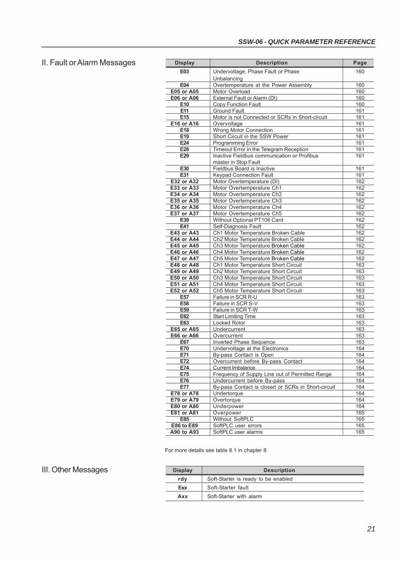
II. Fault or Alarm Messages Display Description Page
E03 Undervoltage, Phase Fault or Phase 160Unbalancing
E04 Overtemperature at the Power Assembly 160E05 or A05 Motor Overload 160E06 or A06 External Fault or Alarm (DI) 160
E10 Copy Function Fault 160E11 Ground Fault 161E15 Motor is not Connected or SCRs in Short-circuit 161
E16 or A16 Overvoltage 161E18 Wrong Motor Connection 161E19 Short Circuit in the SSW Power 161E24 Programming Error 161E28 Timeout Error in the Telegram Reception 161E29 Inactive Fieldbus communication or Profibus 161
master in Stop FaultE30 Fieldbus Board is Inactive 161E31 Keypad Connection Fault 161
E32 or A32 Motor Overtemperature (DI) 162E33 or A33 Motor Overtemperature Ch1 162E34 or A34 Motor Overtemperature Ch2 162E35 or A35 Motor Overtemperature Ch3 162E36 or A36 Motor Overtemperature Ch4 162E37 or A37 Motor Overtemperature Ch5 162
E39 Without Optional PT106 Card 162E41 Self-Diagnosis Fault 162
E43 or A43 Ch1 Motor Temperature Broken Cable 162E44 or A44 Ch2 Motor Temperature Broken Cable 162E45 or A45 Ch3 Motor Temperature Broken Cable 162E46 or A46 Ch4 Motor Temperature Broken Cable 162E47 or A47 Ch5 Motor Temperature Broken Cable 162E48 or A48 Ch1 Motor Temperature Short Circuit 163E49 or A49 Ch2 Motor Temperature Short Circuit 163E50 or A50 Ch3 Motor Temperature Short Circuit 163E51 or A51 Ch4 Motor Temperature Short Circuit 163E52 or A52 Ch5 Motor Temperature Short Circuit 163
E57 Failure in SCR R-U 163E58 Failure in SCR S-V 163E59 Failure in SCR T-W 163E62 Start Limiting Time 163E63 Locked Rotor 163
E65 or A65 Undercurrent 163E66 or A66 Overcurrent 163
E67 Inverted Phase Sequence 163E70 Undervoltage at the Electronics 164E71 By-pass Contact is Open 164E72 Overcurrent before By-pass Contact 164E74 Current Imbalance 164E75 Frequency of Supply Line out of Permitted Range 164E76 Undercurrent before By-pass 164E77 By-pass Contact is closed or SCRs in Short-circuit 164
E78 or A78 Undertorque 164E79 or A79 Overtorque 164E80 or A80 Underpower 164E81 or A81 Overpower 165
E85 Without SoftPLC 165E86 to E89 SoftPLC user errors 165A90 to A93 SoftPLC user alarms 165
III. Other Messages
For more details see table 8.1 in chapter 8.
Display Description
rdy Soft-Starter is ready to be enabled
Exx Soft-Starter fault
Axx Soft-Starter with alarm
22
SAFETY NOTICES
This Manual contains all necessary information for the correct installationand operation of the SSW-06 Soft-Starter.The SSW-06 Instruction Manual has been written for qualified personnelwith suitable training or technical qualifications to operate this type ofequipment.
The following Safety Notices will be used in this Manual:
DANGER!If the recommended Safety Instructions are not strictly observed, seriousor fatal injuries of personnel and/or equipment damage can occur.
ATTENTION!Failure to observe the recommended Safety Procedures can lead tomaterial damage.
NOTE!The content of this Manual supplies important information for the correctunderstanding of operation and proper performance of the equipment.
1.1 SAFETY NOTICESIN THE MANUAL
1.2 SAFETY NOTICES ONTHE PRODUCT
The following symbols may be attached to the product, serving as SafetyNotices:
High Voltages.
Components are sensitive to electrostatic discharge. Do not touchthem without following proper grounding procedures.
Mandatory connection to ground protection (PE).
Shield connection to ground.
CHAPTER 1
CHAPTER 1 - SAFETY NOTICES
23
NOTE!In this Manual, qualified personnel are defined as people that are trained to:
1. Install, ground, power-up and operate the SSW-06 according to thisMa nual and the local required safety procedures;
2. Use of safety equipment according to the local regulations;3. Administer First Aid Treatment.
DANGER!Always disconnect the main power supply before touching any electricalcomponent associated with the SSW-06 Soft-Starter.High voltages and spinning parts (fans) may be present even after switchingoff the power supply. Wait at least 3 minutes for the complete discharge of thecapacitors and until the fans stopped.Always connect the equipment frame to the protection earth (PE) in theappropriate place for this.
ATTENTION!All electronic boards have components that are sensitive to electrostaticdischarges. Never touch any of the electrical components or connectors withoutfollowing proper grounding procedures. If necessary to do so, touch the properlygrounded metallic frame or use a suitable ground strap.
NOTE!Soft-Starter SSW-06 can interfere with other electronic equipment. In order toreduce this interference, adopt the measures recommended in Section 3“Installation”.
NOTE!Read this entire manual carefully and completely before installing or operatingthe Soft-Starter SSW-06.
NOTE!This product is only available for elevator duty on US market.
Do not apply a high voltage (High Pot) test on the Soft-Starter SSW-06!If this test is necessary, contact the manufacturer.
DANGER!Only qualified personnel should plan or implement the installation, start-up,operation and maintenance of this equipment. Personnel must review this entireManual before attempting to install, operate or troubleshoot the SSW-06.These personnel must follow all safety instructions included in this Manualand/or defined by local regulations.Failure to comply with these instructions may result in personal injury and/orequipment damage.
1.3 PRELIMINARYRECOMMENDATIONS
24
GENERAL INFORMATION
This chapter defines the contents and purpose of this manual anddescribes the main characteristics of the SSW-06 Soft-Starter.Identification of the SSW-06, receiving and storage requirements arealso provided.
This manual is divided into 10 chapters, providing information to theuser on how to receive, install, start-up and operate the Soft-StarterSSW-06.
Chapter 1 - Safety Notices;Chapter 2 - General information, receiving and storing of the SSW-06;Chapter 3 - Information about installation and connection of the
Soft-Starter SSW-06 power and control circuit, how toinstall options and recommended setups;
Chapter 4 - Using the Keypad (Human Machine Interface - HMI);Chapter 5 - Information about running and steps to be followed;Chapter 6 - Detailed description of all Soft-Starter SSW-06
programming parameters;Chapter 7- Information and suggestions on how to program the
types of control and protections;Chapter 8 - Information about diagnostics and troubleshooting,
cleaning instructions and preventive maintenance;Chapter 9 - SSW-06 Soft-Starter optional devices;Chapter 10 - Tables and technical information about the power lines
of the Soft-Starter SSW-06.
This manual provides information for the correct use of the Soft-StarterSSW-06. Due to the various functions of the Soft-Starter SSW-06 manydifferent modes of operation are possible.As the Soft-Starter SSW-06 can be applied in several ways, it isimpossible to describe here all application possibilities, neither canWEG assume any responsibility when the Soft-Starter SSW-06 is notused according to this manual.No part of this manual may be reproduced in any form, without writtenpermission from WEG.
It is important to note the software version installed in the Soft-StarterSSW-06, since it defines the functions and the programming parametersof the Soft-Starter. This manual refers to the software version indicatedon the inside cover. For example, the version 1.0X applies to versions1.00 to 1.09, where “X” is a variable that will change due to minor softwarerevisions.The software version can be read in the parameter P023.
The Soft-Starter SSW-06 is a high performance Drive that permits thestart control of three-phase AC induction motors. The Soft-StarterSSW-06 prevents mechanical shocks on the load and current peaksin the supply line.Among the main characteristics of this product is its line and connectionfault detection capacity thus enabling the customer to choose the bestway of protecting his motor, such as:
2.1 ABOUT THIS MANUAL
2.2 SOFTWARE VERSION
2.3 ABOUT THESOFT- STARTERSSW-06
CHAPTER 2
CHAPTER 2 - GENERAL INFORMATION
25
Programmable protections against line undervoltage and overvoltage,and line phase imbalance;
Programmable protections against motor undercurrent andovercurrent, and current imbalance between phases of the motor;
Thermal class may be programmed up to Class 45 for large motors.The thermal memory is saved on EEPROM in case of an electronicsupply fault.
Special functions such as: Display of the number of hours, running time, supply voltage phase,
motor current per phase, motor current in amperes, motor currentas a % of the Soft-Starter SSW-06 nominal current and the nominalcurrent as a % of the motor current, status of the digital inputs andoutputs;
Setting sequence after reset to factory default; Very flexible selection of start/stop control type, enabling the following
selections: Voltage Ramp, Constant Current Limiting or by Ramp,Pump Control and Constant, Linear or Quadratic Torque Control;
Totally flexible Torque Control providing very high performance forthe most demanding applications;
Possibility of using all digital inputs, digital outputs and analogoutputs as remote PLC via Serial and Fieldbus communication;
Possibility of line voltage measurements monitoring by a supervisoryimplemented through Serial or Fieldbus communication;
Monitoring and programming via software SuperDrive G2. Indication of starting and full voltage diagnostics, and faults.
Control Hardware: Keypad, referred to as the Human Machine Interface (HMI) with
Liquid-Crystal Display and easy programming. Fault conditions canbe displayed in several languages.
32Bit Microprocessor calculates the True rms voltage and current; Measurement of the voltage and current in the three phases; Isolated digital input for the motor PTC; Fieldbus boards and RS-485 as options.
Power Hardware: Compact size; Power supply input and output connections:
Models from 10A to 820A - Input from the top and output at thebottom of the SSW-06, with built-in By-pass contactor;Models from 950A to 1400A - Input and output from the bottom,without built-in By-pass contactor;
Easy assembly and maintenance; Measurements of heatsink temperature in models 255A to 820A
through two thermostats:One thermostat to switch-on the internalfans and the other to monitor over-heating;
Soft-Starter SSW-06 can be coupled to the motor by a standardconnection or an inside delta motor connection without requiringoptional devices.
Built-in By-pass contactor makes the Soft-Starter SSW- 06 (Modelsfrom 10A to 820A): More resistant to supply line oscillations after starting; Save energy that would be dissipated through the thyristors after
the start, thus reducing the number of fans required for control panelcooling.
CHAPTER 2 - GENERAL INFORMATION
26
PLC Software Function - SoftPLC The SSW-06 Soft-Starter allows the implementation of programmable
logic controller software in ladder language, the SoftPLC, with anapplicative program capacity of 1 Kbyte.
With the SoftPLC, interlocking logics between digital inputs andoutputs, analog outputs, motor starting logics, among others, canbe created.
This SoftPLC is programmable through the WLP software, accordingto the WLP manual.
Figure 2.1 - Example of SoftPLC software with the WLP editing tool
The example above is the implementation of a clock with hours, minutesand seconds. The hours are showed in parameter P954, the minutesin parameter P953 and the seconds in parameter P952.
CHAPTER 2 - GENERAL INFORMATION
27
Figure 2.2 - Soft-Starter SSW-06 block diagram
Three-PhasePower Supply
CONTROL BOARD
ControlSupply
Digital Inputs
SerialInterfaceRS-232
SerialInterface(optional)RS-485
Fieldbus(optional)
- Profibus DP
- DeviceNet
Analog Outputs
Digital Outputs
ProgrammableAnalog Outputs
AO1 to AO2
ProgrammableDigital Outputs
RL1 to RL3
ProgrammableDigital Inputs
DI1 to DI6
PC, PLC, MFW,SuperDrive G2ModBUS-RTU
PC, PLC
Three-PhaseMotor
OutputVoltage
Input Voltage Current
Supply
POWER BOARD
Keypad(Remote)
Keypad
(1)
(1)
(1)
CPU
PE
PE
(1) Models 950A, 1100A and 1400A do not have an internal By-pass contactor.
CHAPTER 2 - GENERAL INFORMATION
28
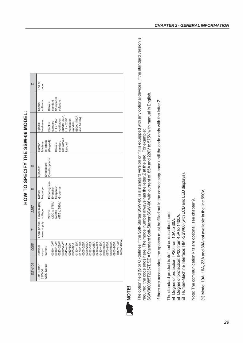
2.4 SOFT-STARTER SSW-06 IDENTIFICATION
Figure 2.3 - Soft-Starter SSW-06 nameplate
Location of Soft-Starter SSW-06 nameplate:
Figure 2.4 - Detail of the Soft-Starter SSW-06 nameplate
VER D ETALH E "A"
X
FRO N TAL
A
VIS TA D E X
SSW-06 Model
Input Data (Voltage, Number ofPhases, Current, Frequency)
Output Data (Voltage, Numberof Phases, Current)
Control Power Supply Data(Voltage, Frequency)
Serial Number
SoftwareVersion
ManufacturingDate
View Detail AIdentification nameplate
of the SSW-06(Internal Cover)
FRONT VIEW VIEW X
WEG ItemNumber
CHAPTER 2 - GENERAL INFORMATION
29
NO
TE
!
The
opt
ion
field
(S o
r O) d
efin
es if
the
Sof
t-S
tart
er S
SW
-06
is a
sta
ndar
d ve
rsio
n or
if it
is e
quip
ped
with
any
opt
iona
l dev
ices
. If t
he s
tand
ard
vers
ion
isre
quire
d, th
e co
de e
nds
here
. The
mod
el n
umbe
r alw
ays
has
the
lette
r Z a
t the
end
. For
exa
mpl
e:S
SW
0600
85T
2257
ES
Z =
Sta
ndar
d S
oft-
Sta
rter
SS
W-0
6 w
ith c
urre
nt o
f 85
A a
nd 2
20V
to 5
75V
with
man
ual i
n E
nglis
h.
If th
ere
are
acce
ssor
ies,
the
spac
es m
ust b
e fil
led
out i
n th
e co
rrec
t seq
uenc
e un
til th
e co
de e
nds
with
the
lette
r Z
.
The
sta
ndar
d pr
oduc
t is
defin
ed a
s de
scrib
ed h
ere:
D
egre
e of
pro
tect
ion:
IP20
from
10A
to 3
0A.
D
egre
e of
pro
tect
ion:
IP00
from
45A
to 1
400A
.
Hum
an-M
achi
ne In
terf
ace:
HM
I-S
SW
06 (w
ith L
CD
and
LE
D d
ispl
ays)
.
Not
e: T
he c
omm
unic
atio
n ki
ts a
re o
ptio
nal,
see
chap
ter 9
.
(1)
Mod
el 1
0A, 1
6A, 2
3A a
nd 3
0A n
ot a
vaila
ble
in th
e lin
e 69
0V.
Nom
inal
outp
utcu
rre
nt:
0010
=10
A(1
)
0016
=16
A(1
)
0023
=23
A(1
)
0030
=30
A(1
)
0045
=45A
0060
=60A
0085
=85
A01
30=1
30A
0170
=170
A02
05=2
05A
0255
=255
A03
12=3
12A
0365
=365
A04
12=4
12A
0480
=480
A06
04=6
04A
0670
=670
A08
20=8
20A
0950
=950
A11
00=1
100A
1400
=14
00A
Th
ee
-ph
as
epo
wer
sup
ply
Pow
er s
uppl
yvo
ltag
e:
2257
=(2
20 to
575
)V57
69 =
(575
to 6
90)V
Man
ual
lang
uage
:
P=
port
ugue
seE
=en
glis
hS
=sp
anis
hG
=ge
rman
Hum
an-
Mac
hine
Inte
rfa
ce(K
eyp
ad
):
Bla
nk =
stan
dard
SI=
with
out
keyp
ad
Spe
cial
soft
wa
re:
Bla
nk =
stan
dard
S1=
spec
ial
soft
wa
re
Spe
cial
hard
war
e:
Bla
nk =
stan
dard
H1
= 1
15V
ven
tila
tion
(mod
el 9
50A
)H
2 =
230
Vve
ntil
atio
n(m
odel
s95
0A, 1
100A
and
1400
A)
So
ft-S
tart
er
SS
W-0
6W
EG
Ser
ies
End
of
code
Op
tion
s:
S=
stan
dard
O=
with
opt
ions
HO
W T
O S
PE
CIF
Y T
HE
SS
W-0
6 M
OD
EL
:S
SW
-06
00
85
T2
25
7E
S_
_
_ _
_ _
Z
CHAPTER 2 - GENERAL INFORMATION
30
2.5 RECEIVING ANDSTORAGE
The SSW-06 is supplied in packaging according to the model:- Models 10A to 205A in a cardboard box;- Models 255A to 365A in a cardboard box over a wooden box;- Models 412A to 1400A in a wooden box.The outside of the packing container has a nameplate that is identicalto that on the Soft-Starter SSW-06. Please check if the nameplate datamatches the ordered data.The models up to 205A must be placed and opened on a table with thehelp of two or more people, open the box, remove the foam protectionand remove Soft-Starter SSW-06.Models greater than 255A must be opened on the floor. Open the boxand, remove the bolts that fasten the Soft-Starter SSW-06 on the pallet.The Soft-Starter SSW-06 must be handled with a hoist.Check if:
The Soft-Starter SSW-06 nameplate data matches the purchaseorder;
The equipment has not been damaged during transportation. If anyproblem is detected, contact the carrier immediately.
If the Soft-Starter SSW-06 is not to be installed immediately, store itwithin its original cardboard box in a clean and dry room (Storagetemperatures between -25°C (-13°F) and 65°C (149ºF)).
31
CHAPTER 3
3.1 MECHANICALINSTALLATION
INSTALLATION AND CONNECTION
This chapter describes the electric and mechanic installation proceduresof the SSW-06 Soft-Starters. The orientations and suggestions mustbe followed for correct product functioning.
3.1.1 Environment Conditions The location of the Soft-Starter SSW-06 installation is an importantfactor to assure good performance and high product reliability.For proper installation of the SSW-06 Soft-Starter, we make the followingrecommendations: Avoid direct exposure to sunlight, rain, excessive moisture or marine
environment; Avoid explosive or corrosive gases and liquids; Avoid excessive vibration, dust or metallic and/or oil particles in the air.
Allowed Environment Conditions: Temperature: 0ºC to 55ºC (32ºF to 131ºF) – Nominal conditions for
models 10A to 820A; 0ºC to 40ºC (32ºF to 104ºF) – Nominalconditions for models 950A to 1400A. 2% current reduction for eachdegree Celsius above the specification in the nominal conditions.
Relative Air Moisture: 5% to 90%, non-condensing. Maximum Altitude:1000m (3,300ft) - nominal conditions.
From 1000m to 4000m (3,300ft to 13,200ft) - with 1% current reductionfor each 100m (330ft) above 1000m (3,300ft).From 2000m to 4000m (6,600ft to 13,200ft) - with 1.1% voltagereduction for each 100m (330ft) above 2000m (6,600ft) sea level.
Degree of Pollution: 2 (according to UL508).Water, condensation or conductive dust/particles are not allowed inthe air.
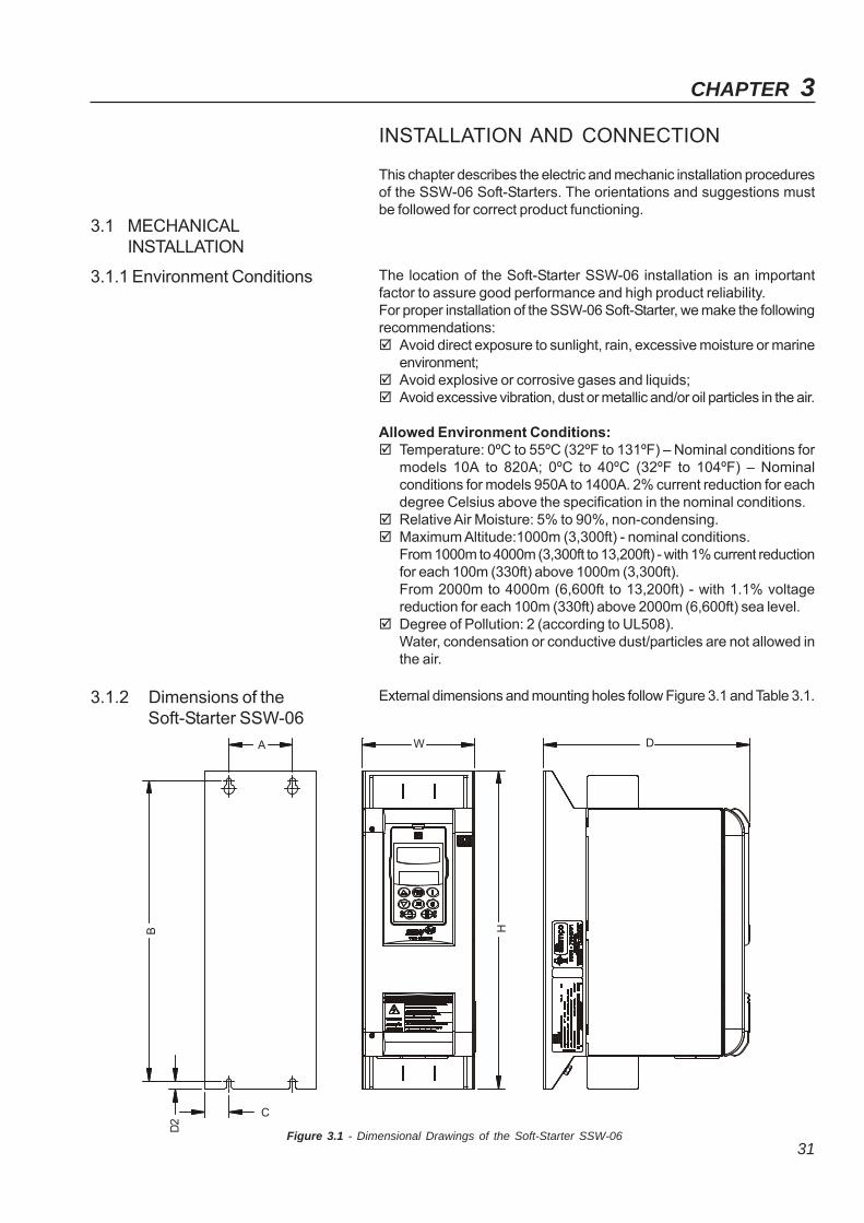
3.1.2 Dimensions of theSoft-Starter SSW-06
External dimensions and mounting holes follow Figure 3.1 and Table 3.1.
Figure 3.1 - Dimensional Drawings of the Soft-Starter SSW-06
A W D
C
B
D2
H
CHAPTER 3 - INSTALLATION AND CONNECTION
32
Free space for cooling airflow must be left open around the SSW-06Soft-Starter, according to figure 3.2. The dimensions of each spaceare described in table 3.2.
Install the Soft-Starter SSW-06 in the vertical position according to thefollowing recommendations:
1) Install the SSW-06 Soft-Starter on a flat surface;2) Do not place heat sensitive components above the SSW-06 Soft-Starter.
ATTENTION!If the Soft-Starters are installed one next to the other, use minimumdistance B.When a Soft-Starter is installed above another, use minimum distanceA+C and avoid the Soft-Starter above from the hot air that comes fromthe Soft-Starter below.
ATTENTION!Foresee independent conduits or electroducts for physically separatingthe signal, control and power conductors (see item 3.2, ElectricalInstallation).
3.1.3 Positioning / Fixing
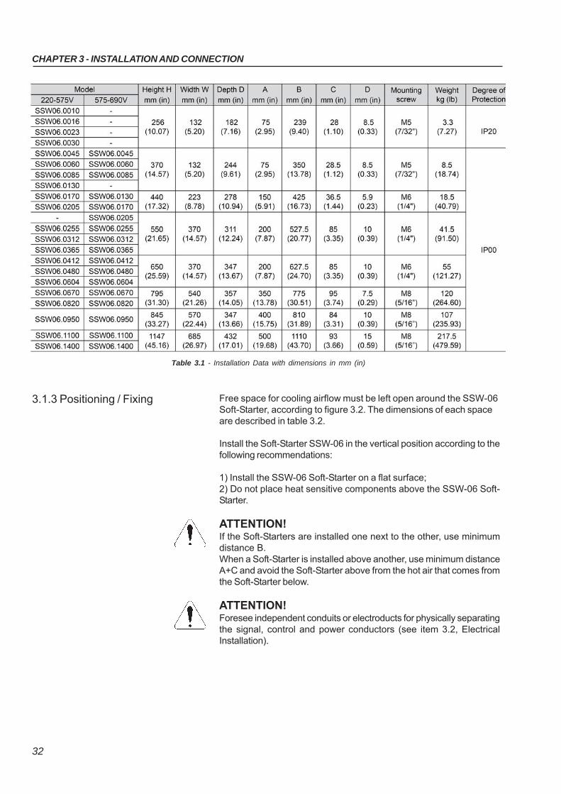
Table 3.1 - Installation Data with dimensions in mm (in)
CHAPTER 3 - INSTALLATION AND CONNECTION
33
Figure 3.2 - Free spaces for cooling
C
A
YBB
Air Flow Outlet
Air Flow Inlet
When the Soft-Starters SSW-06 are installed in panels or closed metallicboxes, adequate cooling is required to ensure that the temperaturearound the inverter will not exceed the maximum allowed temperature.See dissipated power in the table 3.4.
3.1.3.1 Mounting inside a Panel
Table 3.2 - Recommended free spaces
A
mm (in)
150 (5.90)
150 (5.90)
150 (5.90)
150 (5.90)
150 (5.90)
150 (5.90)
150 (5.90)
150 (5.90)
220-575 V
SSW06.0010
SSW06.0016
SSW06.0023
SSW06.0030
SSW06.0045
SSW06.0060
SSW06.0085
SSW06.0130
SSW06.0170
SSW06.0205
-
SSW06.0255
SSW06.0312
SSW06.0365
SSW06.0412
SSW06.0480
SSW06.0604
SSW06.0670
SSW06.0820
SSW06.0950
SSW06.1100
SSW06.1400
B
mm (in)
30 (1.18)
30 (1.18)
30 (1.18)
30 (1.18)
30 (1.18)
30 (1.18)
30 (1.18)
100 (3.93)
C
mm (in)
150 (5.90)
150 (5.90)
150 (5.90)
150 (5.90)
150 (5.90)
150 (5.90)
150 (5.90)
150 (5.90)
Y
mm (in)
50 (1.96)
50 (1.96)
50 (1.96)
50 (1.96)
50 (1.96)
50 (1.96)
50 (1.96)
50 (1.96)
575-690 V
-
-
-
-
SSW06.0045
SSW06.0060
SSW06.0085
-
SSW06.0130
SSW06.0170
SSW06.0205
SSW06.0255
SSW06.0312
SSW06.0365
SSW06.0412
SSW06.0480
SSW06.0604
SSW06.0670
SSW06.0820
SSW06.0950
SSW06.1100
SSW06.1400
Model
CHAPTER 3 - INSTALLATION AND CONNECTION
34
Use the minimum recommended panel dimensions and its coolingrequirements:
NOTE!The fans recommended in table 3.3 are base on:- a working cycle of 10 starts per hour with 3 x In of the SSW-06 for
30s at an ambient temperature of 55°C (131°F) for the models from10A to 820A;
- a working cycle of 5 starts per hour with 30s at an ambienttemperature of 40°C (104°F) for the models from 950A to 1400A.
Table 3.3 - Panel Dimensions and Cooling Requirements
CHAPTER 3 - INSTALLATION AND CONNECTION
35
Table 3.4 - Power losses for panel fan dimensioning
CHAPTER 3 - INSTALLATION AND CONNECTION
36
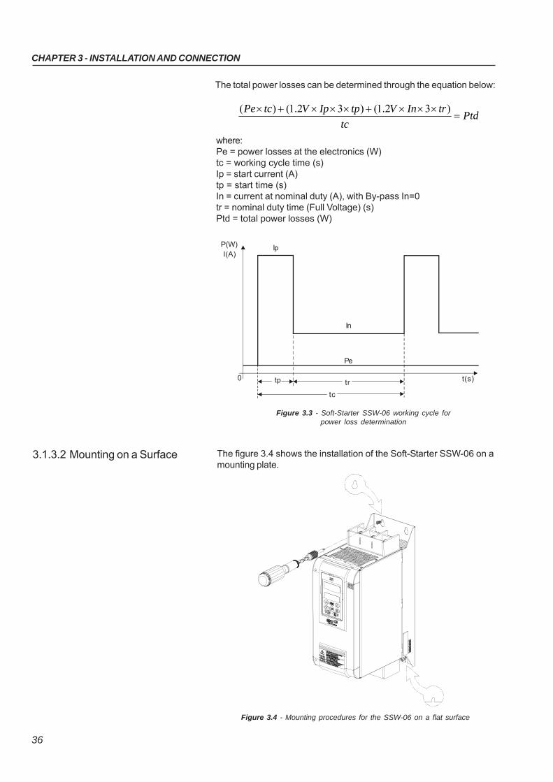
The total power losses can be determined through the equation below:
where:Pe = power losses at the electronics (W)tc = working cycle time (s)Ip = start current (A)tp = start time (s)In = current at nominal duty (A), with By-pass In=0tr = nominal duty time (Full Voltage) (s)Ptd = total power losses (W)
Figure 3.3 - Soft-Starter SSW-06 working cycle forpower loss determination
The figure 3.4 shows the installation of the Soft-Starter SSW-06 on amounting plate.
3.1.3.2 Mounting on a Surface
Figure 3.4 - Mounting procedures for the SSW-06 on a flat surface
P(W)I(A)
Ip
0 tp tr
tc
Pe
In
t(s)
Ptdtc
trInVtpIpVtcPe
)32.1()32.1()(
CHAPTER 3 - INSTALLATION AND CONNECTION
37
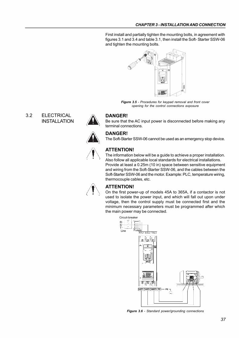
First install and partially tighten the mounting bolts, in agreement withfigures 3.1 and 3.4 and table 3.1, then install the Soft- Starter SSW-06and tighten the mounting bolts.
Figure 3.5 - Procedures for keypad removal and front coveropening for the control connections exposure
3.2 ELECTRICALINSTALLATION
DANGER!Be sure that the AC input power is disconnected before making anyterminal connections.
DANGER!The Soft-Starter SSW-06 cannot be used as an emergency stop device.
ATTENTION!The information below will be a guide to achieve a proper installation.Also follow all applicable local standards for electrical installations.Provide at least a 0.25m (10 in) space between sensitive equipmentand wiring from the Soft-Starter SSW-06, and the cables between theSoft-Starter SSW-06 and the motor. Example: PLC, temperature wiring,thermocouple cables, etc.
ATTENTION!On the first power-up of models 45A to 365A, if a contactor is notused to isolate the power input, and which will fall out upon undervoltage, then the control supply must be connected first and theminimum necessary parameters must be programmed after whichthe main power may be connected.
Figure 3.6 - Standard power/grounding connections
R/1L1 S/3L2 T/5L3
Circuit-breaker
Line Fuses
RST
U/2T1 W/6T3 PEV/4T2 PE
CHAPTER 3 - INSTALLATION AND CONNECTION
38
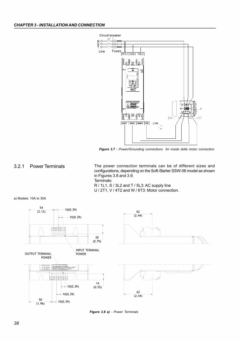
The power connection terminals can be of different sizes andconfigurations, depending on the Soft-Starter SSW-06 model as shownin Figures 3.8 and 3.9.Terminals:R / 1L1, S / 3L2 and T / 5L3: AC supply lineU / 2T1, V / 4T2 and W / 6T3: Motor connection.
3.2.1 Power Terminals
Figure 3.7 - Power/Grounding connections for inside delta motor connection
R/1L1 S/3L2 T/5L3
Circuit-breaker
Line Fuses
RST
a) Models: 10A to 30A
62(2.44)
54(2.12)
10(0.39)
20(0.79)
50(1.96)
10(0.39)
10(0.39)
10(0.39)
10(0.39)
14(0.55)
62(2.44)
INPUT TERMINALPOWEROUTPUT TERMINAL
POWER
Figure 3.8 a) - Power Terminals
U/2T1 W/6T3 PEV/4T2 PE
CHAPTER 3 - INSTALLATION AND CONNECTION
39
* Dimensions in mm (in)
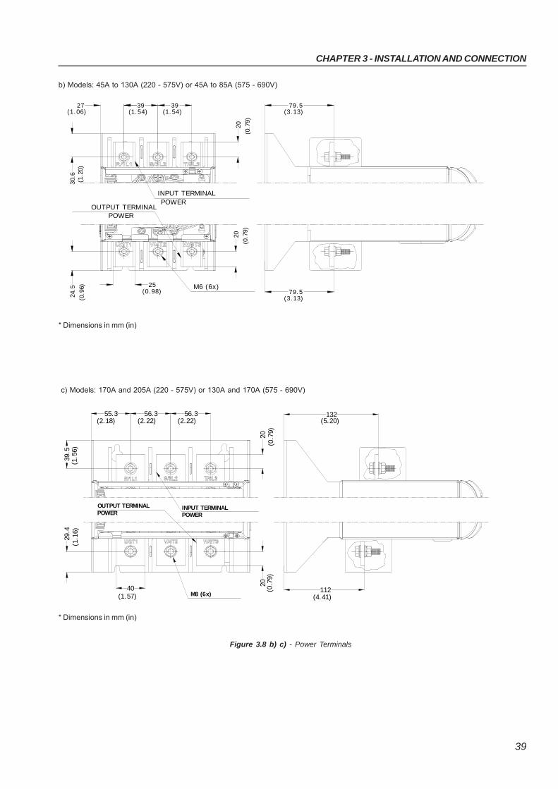
b) Models: 45A to 130A (220 - 575V) or 45A to 85A (575 - 690V)
* Dimensions in mm (in)
c) Models: 170A and 205A (220 - 575V) or 130A and 170A (575 - 690V)
(1.54)39
OUTPUT TERMINAL
27
25
24.5
(0.9
6)
30.6
POWER
(1. 2
0)
(1.06)
M6 (6x)(0.98) 79.5
(3.13)
INPUT TERMINALPOWER
(1.54)39
(3.13)79.5
(0.7
9)
20
(0.7
9)
2 0
29.4
40(1.57) M8 (6x)
(2.18)
39.5
55.3
OUTPUT TERMINALPOWER
(1.1
6)(1
.56)
(2.22)56.3
INPUT TERMINALPOWER
(2.22)56.3 132
(5.20)
112(4.41)
20(0
.79)
(0.7
9)20
Figure 3.8 b) c) - Power Terminals
CHAPTER 3 - INSTALLATION AND CONNECTION
40
d) Models: 255A to 604A (220 - 575V) or 205A to 604A (575-690V)
* Dimensions in mm (in)
e) Models: 670A and 820A
* Dimensions in mm (in)
M 1 0 (1 2 x)
IN P U T TERM IN ALP O W ERO U TP U T TERM IN AL
PO W ER
179.5(7.07)
(7.07)179.5
41(1.61)
41
35
63.559.8
(1.3
8)
(1.61)(2.35) (2.50)63.5 41
(1.61)(2.50)
30
80(3.15)
(1.1
8)
25(0
.98)
(0.9
8)25
M12 (12x)
INPUT TERMINALPOWEROUTPUT TERMINAL
POWER
214.3(8.44)
214.3(8.44)
95(3.74)29
.7(1
.17)
(2.36)60 85
(3.35)60
(3.35)85
(2.36) (2.36)60
120(4.72)
23.9
(0.9
4)
25(0
.98)
25(0
.98)
Figure 3.8 d) e) - Power terminals
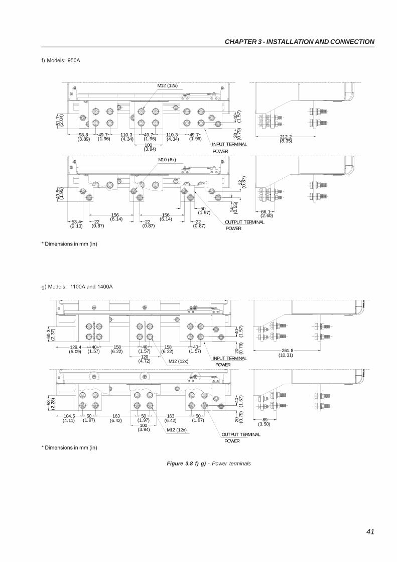
CHAPTER 3 - INSTALLATION AND CONNECTION
41
49.798.8(3.89) (1.96)
51.7
(2. 0
4) 40(1
.57)
20 (0.7
9)
110.3 49.7(4.34) (1.96) (1.96)
49.7(4.34)110.3
49.5
(1. 9
5)
53.4 22(0.87)(2.10)
156(6.14)
(3.94)100
22(0.87)
22156
(0.87)
50(1.97)
22(0
.87)
(0.5
5)14
INPUT TERMINAL
POWER
OUTPUT TERMINALPOWER
M10 (6x)
M12 (12x)
(2.60)66.1
212.2(8.35)
(6.14)
f) Models: 950A
g) Models: 1100A and 1400A
Figure 3.8 f) g) - Power terminals
89(3.50)
(10.31)261.8
104.5(4.11)
163(1.97)
50(6.42)
58(2
.28)
16350(1.97) (6.42) (1.97)
50
(3.94)100
20 (0.7
9)40
(1.5
7)
M12 (12x)
(5.09)129.4 40
(1.57)
60.3
(2.3
7)
158(1.57)
40(6.22)
40(1.57)
158(6.22)
120(4.72) M12 (12x)
2040
(1.5
7)(0
.79)
POWERINPUT TERMINAL
POWER
OUTPUT TERMINAL
* Dimensions in mm (in)
* Dimensions in mm (in)
CHAPTER 3 - INSTALLATION AND CONNECTION
42
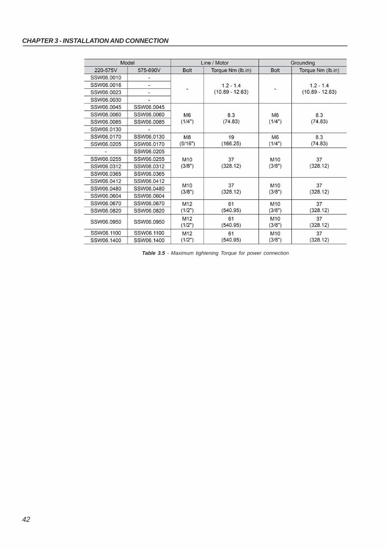
Table 3.5 - Maximum tightening Torque for power connection
CHAPTER 3 - INSTALLATION AND CONNECTION
43
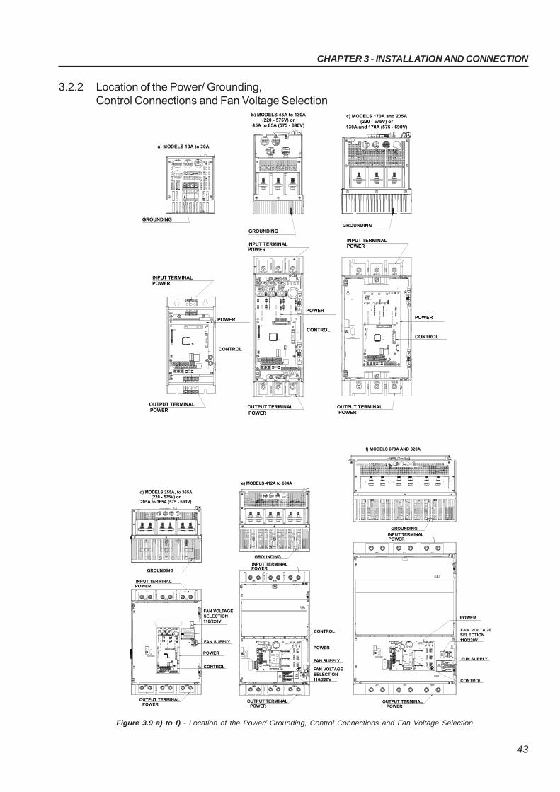
3.2.2 Location of the Power/ Grounding,Control Connections and Fan Voltage Selection
Figure 3.9 a) to f) - Location of the Power/ Grounding, Control Connections and Fan Voltage Selection
POWER
GROUNDING
INPUT TERMINAL
FAN VOLTAGESELECTION110/220V
FAN SUPPLY
CONTROL
OUTPUT TERMINAL
d) MODELS 255A, to 365A(220 - 575V) or
205A to 365A (575 - 690V)
e) MODELS 412A to 604A
f) MODELS 670A AND 820A
OUTPUT TERMINAL
FUN SUPPLY
CONTROL
POWER
FUN VOLTAGESELECTION110/220V
GROUNDING
INPUT TERMINAL
OUTPUT TERMINAL
CONTROL
FAN SUPPLY
FAN VOLTAGESELECTION110/220V
ATENÇÃO!
S ELECIONE A TE NSÃO DOS VENTILA DORES DE ACORDO COM A TENS ÃO APLICADA AOS
B ORNES X1:33 E X1:34
X1E
POWER
ATE NCION!S ELECCIONAR LA TENSION DE LOS V ENTILADORE S DE ACUERDO CON LA TENSION APLICADA A LOS B ORNES X1:33 Y X1:34
ATTENTION!S ELECT THE FA N VOLTAGE IN ACCORDA NCE WITH THE VOLTAGE AP PLIED TO THE
TERMINALS X1:33 AND X1:34
!
INPUT TERMINAL
GROUNDING
POWER
POWER
POWER
POWER POWER POWER
OUTPUT TERMINAL
INPUT TERMINAL
GROUNDING
OUTPUT TERMINAL
CONTROL
INPUT TERMINAL
GROUNDING
CONTROL
POWER
POWER
GROUNDING
INPUT TERMINALPOWER
CONTROL
POWER
OUTPUT TERMINAL
a) MODELS 10A to 30A
b) MODELS 45A to 130A (220 - 575V) or
45A to 85A (575 - 690V)
c) MODELS 170A and 205A (220 - 575V) or
130A and 170A (575 - 690V)
POWER
POWER
POWER
POWER
POWER
FAN VOLTAGE
CHAPTER 3 - INSTALLATION AND CONNECTION
44
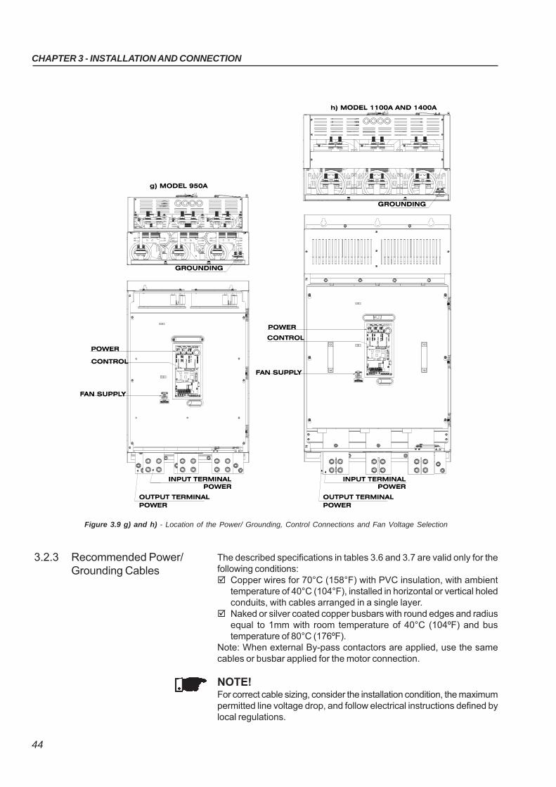
Figure 3.9 g) and h) - Location of the Power/ Grounding, Control Connections and Fan Voltage Selection
3.2.3 Recommended Power/Grounding Cables
The described specifications in tables 3.6 and 3.7 are valid only for thefollowing conditions: Copper wires for 70°C (158°F) with PVC insulation, with ambient
temperature of 40°C (104°F), installed in horizontal or vertical holedconduits, with cables arranged in a single layer.
Naked or silver coated copper busbars with round edges and radiusequal to 1mm with room temperature of 40°C (104ºF) and bustemperature of 80°C (176ºF).
Note: When external By-pass contactors are applied, use the samecables or busbar applied for the motor connection.
NOTE!For correct cable sizing, consider the installation condition, the maximumpermitted line voltage drop, and follow electrical instructions defined bylocal regulations.
CHAPTER 3 - INSTALLATION AND CONNECTION
45
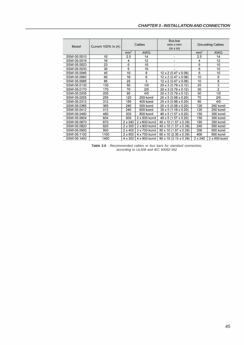
Table 3.6 - Recommended cables or bus bars for standard connection,according to UL508 and IEC 60092-352
CHAPTER 3 - INSTALLATION AND CONNECTION
46
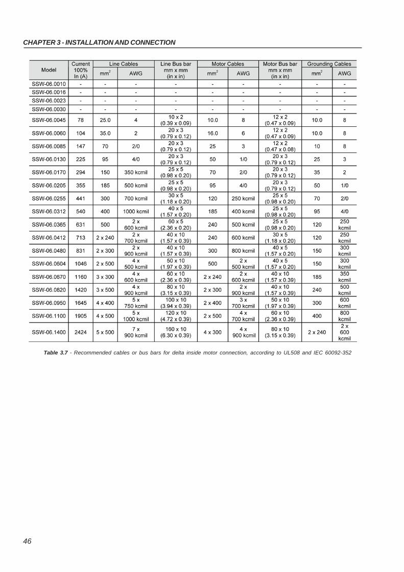
Table 3.7 - Recommended cables or bus bars for delta inside motor connection, according to UL508 and IEC 60092-352
CHAPTER 3 - INSTALLATION AND CONNECTION
47
DANGER!The AC input voltage must be compatible with the Soft-Starter SSW-06nominal voltage.
DANGER!Provide a power supply disconnecting switch. This disconnecting switchmust disconnect the AC input voltage from the Soft-Starter SSW-06,when ever required (for instance during maintenance services).
DANGER!If a disconnect switch or a contactor is inserted in the motor supplyline, DO NOT operate these devices with a running motor or when theSoft-Starter SSW-06 is enabled.
ATTENTION!Control of overvoltage in the line that supplies the Soft-Starter must bemade using surge protection with a voltage of 680Vac (phase to phaseconnection) and energy absorption capacity of 40 joules (for modelsfrom 10A to 205A) and 80 joules (for models from 255A to 1400A), all for220 to 575 Vac models.
NOTE!Use wire sizing and fuses as recommended in tables 3.6, 3.7 and 3.9.The connector tightening torque is as indicated in table 3.5. Use 70ºC(158ºF) copper wires only.
3.2.4 Connection of the PowerSupply to the Soft-Starter
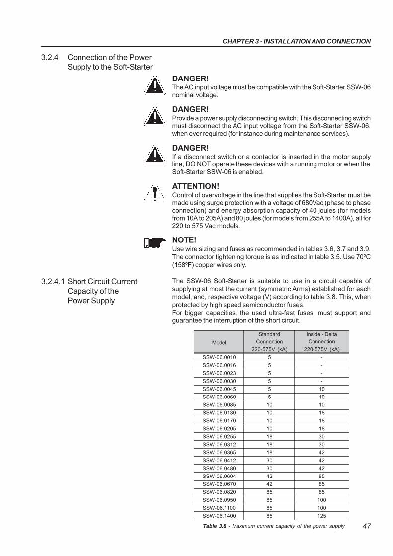
The SSW-06 Soft-Starter is suitable to use in a circuit capable ofsupplying at most the current (symmetric Arms) established for eachmodel, and, respective voltage (V) according to table 3.8. This, whenprotected by high speed semiconductor fuses.For bigger capacities, the used ultra-fast fuses, must support andguarantee the interruption of the short circuit.
3.2.4.1 Short Circuit CurrentCapacity of thePower Supply
StandardConnection
220-575V (kA)
5
5
5
5
5
5
10
10
10
10
18
18
18
30
30
42
42
85
85
85
85
Model
SSW-06.0010
SSW-06.0016
SSW-06.0023
SSW-06.0030
SSW-06.0045
SSW-06.0060
SSW-06.0085
SSW-06.0130
SSW-06.0170
SSW-06.0205
SSW-06.0255
SSW-06.0312
SSW-06.0365
SSW-06.0412
SSW-06.0480
SSW-06.0604
SSW-06.0670
SSW-06.0820
SSW-06.0950
SSW-06.1100
SSW-06.1400
Inside - DeltaConnection
220-575V (kA)
-
-
-
-
10
10
10
18
18
18
30
30
42
42
42
85
85
85
100
100
125
Table 3.8 - Maximum current capacity of the power supply
CHAPTER 3 - INSTALLATION AND CONNECTION
48
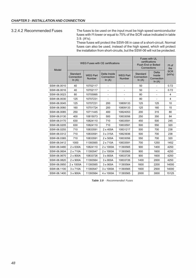
The fuses to be used on the input must be high speed semiconductorfuses with l2t lower or equal to 75% of the SCR value indicated in table3.9. (A2s).These fuses will protect the SSW-06 in case of a short-circuit. Normalfuses can also be used, instead of the high speed, which will protectthe installation from short-circuits, but the SSW-06 will not be protected.
3.2.4.2 Recommended Fuses
Table 3.9 - Recommended Fuses
Model
WEG Fuses with CE certifications
Fuses with UL certifications
Flush End or Bolted Connections
I²t of the
SCR (kA²s) Standard
Connection In (A)
WEG Part Number
Delta Inside Connection
In (A)
WEG Part Number
Standard Connection
In (A)
Delta Inside
Connection In (A)
SSW-06.0010 40 10702117 - - 50 - 0.72
SSW-06.0016 40 10702117 - - 50 - 0.72
SSW-06.0023 80 10705995 - - 80 - 4
SSW-06.0030 125 10707231 - - 80 - 4
SSW-06.0045 125 10707231 200 10809133 125 125 10
SSW-06.0060 160 10701724 200 10809133 125 160 15
SSW-06.0085 250 10711445 400 10824053 200 315 80
SSW-06.0130 400 10815073 500 10833056 250 350 84
SSW-06.0170 630 10824110 710 10833591 450 500 245
SSW-06.0205 630 10824110 710 10833591 500 550 320
SSW-06.0255 710 10833591 2 x 400A 10831217 500 700 238
SSW-06.0312 710 10833591 3 x 315A 10823936 500 700 238
SSW-06.0365 710 10833591 2 x 500A 10833056 550 700 320
SSW-06.0412 1000 11393565 2 x 710A 10833591 700 1250 1452
SSW-06.0480 2 x 630A 10824110 2 x 1000A 11393565 900 1400 4250
SSW-06.0604 2 x 710A 11393547 2 x 1000A 11393565 900 1600 4250
SSW-06.0670 2 x 800A 10833726 3 x 800A 10833726 900 1600 4250
SSW-06.0820 2 x 900A 11393564 3 x 800A 10833726 1400 2000 4250
SSW-06.0950 2 x 1000A 11393565 3 x 900A 11393564 1600 2200 14000
SSW-06.1100 3 x 710A 11393547 3 x 1000A 11393565 1600 2500 14000
SSW-06.1400 3 x 900A 11393564 4 x 1000A 11393565 2000 3000 15125
CHAPTER 3 - INSTALLATION AND CONNECTION
49
DANGER!Power factor correction capacitors should never be fitted to the outputof the Soft-Starter SSW-06 (U / 2T1, V / 4T2 and W / 6T3).
ATTENTION!For the protection based on the current reading and indication to workcorrectly, in case of overload protection, the nominal current of the mo-tor cannot be lower than 30% of the nominal current of the SSW-06Soft-Starter.It is not recommended to use motors with the load working duty lowerthan 50% of its nominal current.
NOTE!Use wire sizing and fuses as recommended in Table 3.6, 3.7 and 3.9.The connector tightening torque is as indicated in Table 3.5. Use 70ºC(158ºF) copper wires only.
NOTE!Soft-Starter SSW-06 is provided with an electronic protection againstmotor overload. This protection must be set according to the specificmotor. When several motors are connected to the same Soft-StarterSSW-06, use individual overload relays for each motor.
The SSW-06 Soft-Starter can be connected to the motor in two ways,according to items 3.2.5.1 and 3.2.5.2.
3.2.5 Connection of theSSW-06 Soft-Starterto the motor
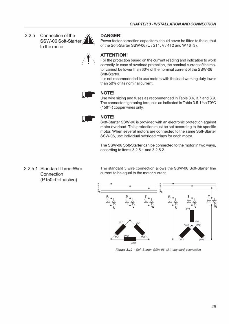
3.2.5.1 Standard Three-WireConnection(P150=0=Inactive)
The standard 3 wire connection allows the SSW-06 Soft-Starter linecurrent to be equal to the motor current.
Figure 3.10 - Soft-Starter SSW-06 with standard connection
1/U1
4/U2 2/V1
5/V26/W2
3/W1
2/V1
5/V2
1/U1
4/U2 6/W2
3/W1
RSTNP E
RSTNP E
R
U
S
V W
T R
U
S
V
T
W
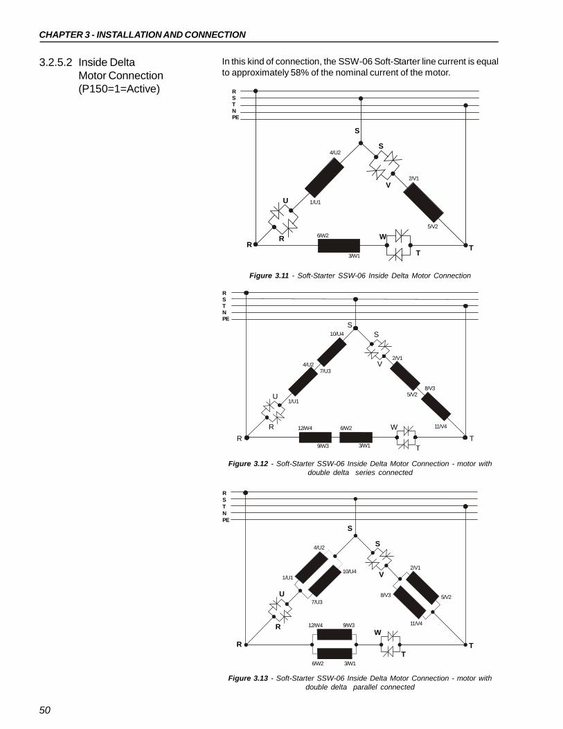
CHAPTER 3 - INSTALLATION AND CONNECTION
50
3.2.5.2 Inside DeltaMotor Connection(P150=1=Active)
In this kind of connection, the SSW-06 Soft-Starter line current is equalto approximately 58% of the nominal current of the motor.
Figure 3.11 - Soft-Starter SSW-06 Inside Delta Motor Connection
Figure 3.12 - Soft-Starter SSW-06 Inside Delta Motor Connection - motor withdouble delta series connected
S
S
V
W
R
R
T
T
U
2/V1
5/V2
6/W2
3/W1
8/V3
11/V4
7/U3
10/U4
12/W4
9/W3
1/U1
4/U2
Figure 3.13 - Soft-Starter SSW-06 Inside Delta Motor Connection - motor withdouble delta parallel connected
1/U1
4/U2
2/V1
5/V2
6/W2
3/W1
RSTNPE
S
S
V
WR
R
TT
U
2/V1
5/V2
6/W2 3/W1
8/V3
11/V412/W4 9/W3
7/U3
10/U41/U1
4/U2
RSTNPE
R
S
W
T
S
R
T
V
U
RSTNPE
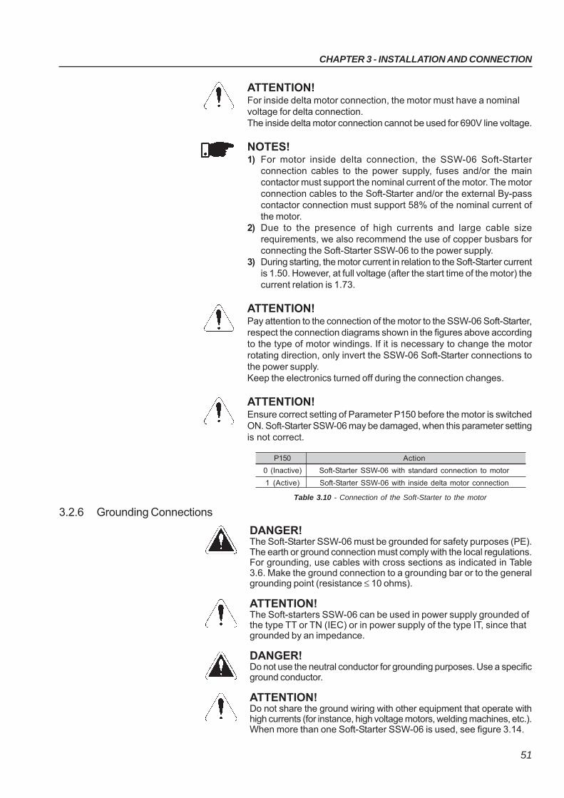
CHAPTER 3 - INSTALLATION AND CONNECTION
51
ATTENTION!For inside delta motor connection, the motor must have a nominalvoltage for delta connection.The inside delta motor connection cannot be used for 690V line voltage.
NOTES!1) For motor inside delta connection, the SSW-06 Soft-Starter
connection cables to the power supply, fuses and/or the maincontactor must support the nominal current of the motor. The motorconnection cables to the Soft-Starter and/or the external By-passcontactor connection must support 58% of the nominal current ofthe motor.
2) Due to the presence of high currents and large cable sizerequirements, we also recommend the use of copper busbars forconnecting the Soft-Starter SSW-06 to the power supply.
3) During starting, the motor current in relation to the Soft-Starter currentis 1.50. However, at full voltage (after the start time of the motor) thecurrent relation is 1.73.
ATTENTION!Pay attention to the connection of the motor to the SSW-06 Soft-Starter,respect the connection diagrams shown in the figures above accordingto the type of motor windings. If it is necessary to change the motorrotating direction, only invert the SSW-06 Soft-Starter connections tothe power supply.Keep the electronics turned off during the connection changes.
ATTENTION!Ensure correct setting of Parameter P150 before the motor is switchedON. Soft-Starter SSW-06 may be damaged, when this parameter settingis not correct.
P150 Action
0 (Inactive) Soft-Starter SSW-06 with standard connection to motor
1 (Active) Soft-Starter SSW-06 with inside delta motor connection
DANGER!The Soft-Starter SSW-06 must be grounded for safety purposes (PE).The earth or ground connection must comply with the local regulations.For grounding, use cables with cross sections as indicated in Table3.6. Make the ground connection to a grounding bar or to the generalgrounding point (resistance ≤ 10 ohms).
ATTENTION!The Soft-starters SSW-06 can be used in power supply grounded ofthe type TT or TN (IEC) or in power supply of the type IT, since thatgrounded by an impedance.
DANGER!Do not use the neutral conductor for grounding purposes. Use a specificground conductor.
ATTENTION!Do not share the ground wiring with other equipment that operate withhigh currents (for instance, high voltage motors, welding machines, etc.).When more than one Soft-Starter SSW-06 is used, see figure 3.14.
3.2.6 Grounding Connections
Table 3.10 - Connection of the Soft-Starter to the motor
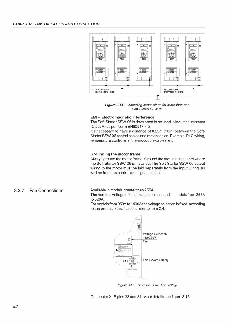
CHAPTER 3 - INSTALLATION AND CONNECTION
52
EMI – Electromagnetic interference:The Soft-Starter SSW-06 is developed to be used in industrial systems(Class A) as per Norm EN60947-4-2.It’s necessary to have a distance of 0.25m (10in) between the Soft-Starter SSW-06 control cables and motor cables. Example: PLC wiring,temperature controllers, thermocouple cables, etc.
Grounding the motor frame:Always ground the motor frame. Ground the motor in the panel wherethe Soft-Starter SSW-06 is installed. The Soft-Starter SSW-06 outputwiring to the motor must be laid separately from the input wiring, aswell as from the control and signal cables.
Figure 3.14 - Grounding connections for more than oneSoft-Starter SSW-06
Grounding barInternal to the Panel
Grounding barInternal to the Panel
3.2.7 Fan Connections Available in models greater than 255A.The nominal voltage of the fans can be selected in models from 255Ato 820A.For models from 950A to 1400A the voltage selection is fixed, accordingto the product specification, refer to item 2.4.
Figure 3.15 - Selection of the Fan Voltage
X1 E
ALIM EN TAÇ ÃOVEN TILAD O R
S E LEÇ ÃO
D E TE N S ÃO1 1 0 /2 2 0 V
ATENÇÃO!
SELECIONE A TENSÃO DOS VENTILADORES
DE ACORDO COM A TENSÃO APLICADA AOS BORNES X1:33 E X1:34
ATTENTION!SELECT THE FAN VOLTAGE IN ACCORDANCE WITH THE VOLTAGE APPLIED TO THE TERMINALS X1:33 AND X1:34
ATENCION!SELECCIONAR LA TENSION DE LOS VENTILADORES DE ACUERDO CON LA TENSION APLICADA A LOS BORNES X1:33 Y X1:34
!
Voltage Selection110/220VFan
Fan Power Supply
Connector X1E pins 33 and 34. More details see figure 3.16.
CHAPTER 3 - INSTALLATION AND CONNECTION
53
3.2.8 Signal and ControlConnections
The signal connections (analog outputs) and control (digital inputs and relayoutputs) are made on the electronic board connectors.Connectors:CCS6 and CPS61 on the models 10A to 30A.CCS6 and CPS63 or CPS66 on the models 45A to 365A and 950A to 1400A.CCS6 and CPS64 or CPS65 on the models 412A to 820A.
Note: NC = Normally Closed ContactNO = Normally Open ContactC = Common
Figure 3.16 - Control Terminal Description
NOTE!For models from 255A to 820A the fans are switched on if the heatsinktemperature is above 70ºC (158ºF). Do not forget to connect the fan powersupply and select the fan supply voltage for the models higher or equalthan 255A.
PTC
CHAPTER 3 - INSTALLATION AND CONNECTION
54
Figure 3.17 - Control connector positions
Figure 3.18 - Connection diagram of the digital inputs using the auxiliary internal source
Figure 3.19 - Connection diagram of the digital inputs using an external source
For signal and control wire installation, adopt the followingprocedures:1) The connections of the SSW-06 digital inputs can be carried out inseveral ways. They can be supplied by auxiliary internal +24Vdc sourceby using the 0V as a common point or by the +24Vdc source. Dependingon the application requirements,they can also be supplied by external+24Vdc source, connected to PLCs, by using the 0V as commonpoint or by the +24Vdc source:
Connector X1B
3 DI1
4 DI2
5 DI3
6 DI4
7 DI5
8 COM
9 COM
10 DGND
11 24Vdc
Connector X1B
3 DI1
4 DI2
5 DI3
6 DI4
7 DI5
8 COM
9 COM
10 DGND
11 24Vdc
Connector X1B
3 DI1
4 DI2
5 DI3
6 DI4
7 DI5
8 COM
9 COM
10 DGND
11 24Vdc
Connector X1B
3 DI1
4 DI2
5 DI3
6 DI4
7 DI5
8 COM
9 COM
10 DGND
11 24Vdc
To be used for grounding of shield ofthe signal and control cables
XO
X1A
X1B X1C X2
X1D
24Vdc
+
24Vdc
+
CHAPTER 3 - INSTALLATION AND CONNECTION
55
Table 3.11 - Wiring separation distances
If the crossing of these cables is unavoidable, install them perpendicu-lar, maintaining a minimum separation distance of 5cm (2 in) at thecrossing point.
Connect the shield as shown below:
6) For wiring distances longer than 50m (150ft), it is necessary to usegalvanic isolators for the X1B:3...17signals.
7) Relays, contactors, solenoids or electromagnetic braking coilsinstalled near Soft-Starters can generate interference in the controlcircuit. In order to eliminate this interference, connect RC suppressorsin parallel with the coils of AC relays. Connect a free - wheeling diodein case of DC relays/coils.
8) When an external keypad is used (Refer to Chapter 9), separate thecable that connects the keypad to the Soft-Starter SSW-06 fromother cables, maintaining a minimum distance of 10cm (4 in) betweenthem.
Wiring Length Min. separation distance
≤ 30 m (98.4 ft) ≥ 10 cm (3.94 in)
> 30 m (98.4 ft) ≥ 25 cm (9.84 in)
Insulate with tape
Do not ground
Soft-Starter side
Connect to ground
Screw located on the CCS6 board
Figure 3.20 - Shield connection
NOTE!1) The auxiliary electronic power supply of the SSW-06 Soft-Starter of
+24Vdc shall only be used for the supply of the digital inputs.2) The SSW-06 Soft-Starter factory default is with the pins 8 and 10 of
the X1B connector bridged (wire bridge).3) Cable cross section (0.5 to 1.5) mm2.4) Maximum torque: 0.50 N.m (4.50 ibf.in).5) X1B wiring must be connected with shielded cables and installed
separately from other wiring (power, control at 110V/220V, etc.),according to Table 3.11.
CHAPTER 3 - INSTALLATION AND CONNECTION
56
An optional Profibus DP or DeviceNet Communication board can beattached to this connector.For more details see the Profibus DP or DeviceNet CommunicationManual of the Soft-Starter SSW-06 and chapter 9.
3.2.11 XC6 FieldbusCommunication BoardConnection
Figure 3.21 - X2, XC6 and XC8 Connector
3.3 RECOMMENDEDSET-UPS
In this item some suggestive set-ups are presented, which can beused completely or in part to elaborate the desired control.The main warnings, for all the suggestive set-up, listed below, are relatedin the diagrams through their respective numbers.
NOTES!For the protection of all of the electrical installation, the use offuses or circuit breakers in the main power supply circuit isnecessary.The use of high speed semiconductor fuses are not necessaryfor the functioning of the SSW-06 Soft-Starter, but its use isrecommended for the complete protection of the SSW-06.
The transformer “T1” is optional and should be used when theline voltage is different from the electronics and fan voltage;
To protect the motor against destruction by possible short-circuits in the power circuit of the Soft-Starter SSW-06 use anisolating contactor (K1) or circuit-breaker (Q1);
3.2.9 RS-232, X2 SerialCommunication Connection
3.2.10 XC8 SerialCommunication BoardConnection
This connector is used to make a standard RS-232 communicationline between the Soft-Starter SSW-06 and a PC and/or PLC.For more details see the Serial Communication Manual of theSoft-Starter SSW-06.
An optional board of serial communication, standard RS-485 withgalvanic insulation, or USB, can be attached to this connector.For more details see the Serial Communication Manual of theSoft-Starter SSW-06 and chapter 9.
1
2
3
CHAPTER 3 - INSTALLATION AND CONNECTION
57
X1E (33 and 34) is only available on the models fitted with coolingfans;
For integral motor protection the installation of one or more PTCthermistors (PTC at DI6) or thermostats (external fault at DI4 toDI6) is recommended;
Remember that when a command via two-wire digital input isused (the switch is normally open with retention), every time thepower supply returns, after any fault, the motor starts immediatelyif the switch remains closed;
In case of maintenance services, remove the power supply fusesor disconnect the power supply, thus ensuring completeequipment disconnection from power.
An emergency stop can be obtained by disconnecting theelectronics power supply.
The contactors must be of the same model and must supportthe motor starting current. For safety reasons, auxiliary contactsmust be used to keep both contactors from closing at the sametime.
Use a digital input set to “General Enable” to disable the motorwithout braking. Use a digital input set to “No Braking”, for safetyreasons, with the possibility of fitting a motor stop sensor todisable the braking.
The use of an external By-pass contactor is optional for models950A to 1400A that do not have an internal By-pass contactor.This contactor is also recommended, in models with an internalBy-pass, for use in applications where the motor can frequentlypresent a locked rotor during the full operation cycle.
To maintain the current indications and protections, when usingthe external By-pass contactor, it is necessary to place thecurrent transformers on the Soft-Starter output. The currenttransformers must be placed in the correct positions anddirections as indicated. For more details see chapter 9.6.
5
6
4
7
8
9
10
11
12
CHAPTER 3 - INSTALLATION AND CONNECTION
58
3.3.1 Recommended Set-up using Keypad Command with Isolating Contactor
Figure 3.22 - Recommended Set-up using Keypad command with isolating contactor
See notes in the item 3.3
+ toM3~
PTC
RS
T
PE
K1
R S T 1 2 PE 33 34
X1EX1A
18 19
RL1 RL2
20 21 22 23 24
RL3
X1C
X1B
Dl1
3Dl2
4
Dl3
5
Dl4
6
Dl5
7
COM
8 9
0V
10
24V
11
PTCB A
12 13U V W
Fault
T1
K1
P279 =6
P277 =1
P229 =0
P220 =0
3.3.2 Recommended Set-up using Keypad Command with Circuit-breaker
Figure 3.23 - Recommended Set-up using Keypad command with circuit-breaker
See notes in the item 3.3
RS
T
PE
Q1
R S T 1 2 PE 33 34
X1EX1A
18 19
RL1 RL2
20 21 22 23 24
RL3
X1C
X1B
Dl1
3
Dl2
4
Dl3
5
Dl4
6
Dl5
7COM
8 9
0V
10
24V
11
PTCB A
12 13U V W
Fault
T1
Q1Circuit-breaker withunder voltagerelease
Q2
+ to
M3~
PTC
P279 =7
P229 =0
P220 =0
CHAPTER 3 - INSTALLATION AND CONNECTION
59
3.3.3 Recommended Set-up with Command via Two-wire Digital Inputs
Figure 3.24 - Recommended set-up with command via two-wire digital inputs
+ toM3~
PTC
RS
T
PE
K1
R S T 1 2 PE 33 34
X1EX1A
18 19
RL1 RL2
20 21 22 23 24
RL3
X1C
X1B
Dl1
3
Dl2
4
Dl3
5Dl4
6
Dl5
7COM
8 9
0V
10
24V
11
PTCB A
12 13U V W
Fault
T1
K1
Sta
rt/
Sto
p 6
3.3.4 Recommended Set-up with Command via Three-wire Digital Inputs
Figure 3.25 - Recommended set-up with command via three-wire digital inputs
+ to
M3~
PTC
RS
T
PE
K1
R S T 1 2 PE 33 34
X1EX1A
18 19
RL1 RL2
20 21 22 23 24
RL3
X1C
X1B
Dl1
3
Dl2
4
Dl3
5Dl4
6Dl5
7
COM
8 9
0V
1024V
11
PTCB A
12 13U V W
Fault
T1
K1
Sta
rt
Sto
p
See notes in the item 3.3
See notes in the item 3.3
P230 =1
P220 =1
P263 =1
P279 =6
P277 =1
P277 =1
P264 =1
P230 =1
P220 =1
P279 =6
P263 =2
CHAPTER 3 - INSTALLATION AND CONNECTION
60
3.3.6 Recommended Set-up with Command via Three-wire Digital Input or SerialCommunication
Figure 3.27 - Recommended set-up with command via three-wire digital input or serialcommunication
See notes in the item 3.3
+ to
M3~
RS
T
PE
K1
R S T 1 2 PE 33 34
X1EX1A
18 19
RL1 RL2
20 21 22 23 24
RL3
X1C
X1B
Dl1
3
Dl2
4
Dl3
5
Dl4
6Dl5
7
COM
8 9
0V
1024V
11
PTCB A
12 13U V W
Fault
T1
K1
Sta
rt
Sto
p
PTC
X2PC
Lo
cal
Rem
ote
3.3.5 Recommended Set-up with Command via Three-wire Digital Input and Inside DeltaMotor Connection
Figure 3.26 - Recommended set-up with command via three-wire digital input and insidedelta motor connection
See items 3.2.5.2 and 3.3
+ to
M3~
RS
T
PE
K1
R S T 1 2 PE 33 34
X1EX1A
18 19
RL1 RL2
20 21 22 23 24
RL3
X1C
X1B
Dl1
3
Dl2
4
Dl3
5
Dl4
6Dl5
7
COM
8 9
0V
1024V
11
PTCB A12 13U V W
Fault
T1
K1
Sto
p
Sta
rt
PTC
P264 =1
P230 =1
P220 =1
P150 =1
P277 =1
P279 =6
P263 =2
P264 =1
P230 =2
P229 =1
P220 =4
P277 =1
P279 =6
P263 =2
CHAPTER 3 - INSTALLATION AND CONNECTION
61
3.3.7 Recommended Set-up with Command via Three-wire Digital Input or FieldbusCommunication
Figure 3.28 - Recommended set-up with command via three-wire digital input or fieldbuscommunication
See notes in the item 3.3
+ to
M3~
RS
T
PE
K1
R S T 1 2 PE 33 34
X1EX1A
18 19
RL1 RL2
20 21 22 23 24
RL3
X1C
X1B
Dl1
3
Dl2
4Dl3
5Dl4
6
Dl5
7
COM
8 9
0V
10
24V
11
PTCB A12 13U V W
Fault
T1
K1
PTC
X2
PLC
Lo
cal
Rem
ote
Sta
rt
Sto
p
3.3.8 Recommended Set-up with Command via Digital Inputs and direction of rotation
Figure 3.29 - Recommended Set-up with Command via Digital Inputs and direction of rotation
10+ to
M3~
RS
T
PE
K1
R S T 1 2 PE 33 34
X1EX1A
18 19
RL1 RL2
20 21 22 23 24
RL3
X1C
X1BDl1
3
Dl2
4Dl3
5Dl4
6
Dl5
7
COM
8 90V
10
24V
11
PTCB A12 13U V W
Fault
T1
K1
PTC
Sta
rt
Sto
p
K2 K2
Dir
ect
ion
of
Ro
tatio
n
See notes in the item 3.3
P264 =1
P230 =3
P229 =1
P220 =4
P277 =1
P279 =6
P263 =2
P264 =1
P231 =1
P230 =1
P220 =1
P266 =1
P277 =4
P278 =4
P279 =6
P263 =2
P620 =0
CHAPTER 3 - INSTALLATION AND CONNECTION
62
3.3.9 Recommended Set-up with Command via Digital Inputs and Reverse Braking
Figure 3.30 - Recommended Set-up with Command via Digital Inputs and Reverse Braking
3.3.10 Recommended Set-up with Command via Digital Inputs and Optimal Braking
Figure 3.31 - Recommended Set-up with Command via Digital Inputs and Optimal Braking
10+ to
M3~
RS
T
PE
K1
R S T 1 2 PE 33 34
X1EX1A
18 19
RL1 RL2
20 21 22 23 24
RL3
X1C
X1B
Dl1
3
Dl2
4Dl3
5
Dl4
6
Dl5
7
COM
8 9
0V
10
24V
11
PTCB A12 13U V W
Fault
T1
K1
PTCS
tart
Sto
p
K2 K2
With
ou
tB
raki
ng
Ge
n. E
na
ble
+ toM3~
RS
T
PE
K1
R S T 1 2 PE 33 34
X1EX1A
18 19
RL1 RL2
20 21 22 23 24
RL3
X1C
X1B
Dl1
3
Dl2
4Dl3
5Dl4
6
Dl5
7
COM
8 9
0V
10
24V
11
PTCB A12 13U V W
Fault
T1
K1
PTC
Sta
rt
Sto
p
With
ou
tB
raki
ng
Ge
n. E
na
ble
See notes in the item 3.3
See notes in the item 3.3
P265 =1
P264 =1
P230 =1
P220 =1
P266 =5
P277 =4
P278 =4
P279 =6
P500 =1
P263 =2
P265 =1
P264 =1
P230 =1
P220 =1
P266 =5
P277 =1
P279 =6
P500 =2
P263 =2
CHAPTER 3 - INSTALLATION AND CONNECTION
63
3.3.11 Recommended Set-up with Command via Digital Inputs and DC-Braking
Figure 3.32 - Recommended Set-up with Command via Digital Inputs and DC-Braking
3.3.12 Recommended Set-up with Command via Digital Inputs and External By-pass Contactor
Figure 3.33 - Recommended Set-up with Command via Digital Inputs and External By-passContactor
+ to
M3~
RS
T
PE
K1
R S T 1 2 PE 33 34
X1EX1A
18 19
RL1 RL2
20 21 22 23 24
RL3
X1C
X1B
Dl1
3
Dl2
4
Dl3
5Dl4
6
Dl5
7
COM
8 9
0V
10
24V
11
PTCB A12 13
U V W
Fault
T1
K1
PTC
Sta
rt
Sto
p
K2
With
ou
tB
raki
ng
Ge
n. E
na
ble
K2
+ to
M3~
RS
T
PE
K1
R S T 1 2 PE 33 34
X1EX1A
18 19
RL1 RL2
20 21 22 23 24
RL3
X1C
X1B
Dl1
3
Dl2
4
Dl3
5
Dl4
6
Dl5
7
COM
8 9
0V
1024V
11
PTCB A12 13U V W
Fault
T1
K1
PTC
Sta
rt
Sto
p
K2
K2X1D
27
28
29
30
31
32
Re
dB
lack
Bla
ckR
ed
Bla
ckR
ed
See notes in the item 3.3
See notes in the item 3.3
P265 =1
P264 =1
P230 =1
P220 =1
P266 =5
P277 =1
P279 =6
P500 =3
P278 =5
P263 =2
P264 =1
P230 =1
P220 =1
P140 =1
P277 =1
P278 =3
P279 =6
P263 =2
CHAPTER 3 - INSTALLATION AND CONNECTION
64
Electrical connection between
two signals
Connection Terminals
Coil - Relay, Contactor
Normally Open Contact (NO)
Indicator light
Circuit-breaker
(opens under load)
Resistor
Capacitor
3.3.13 Symbols
Fuse
Thyristor/SCR
Three-phase Motor
Emergency Button
Transformer
N.O. Contact (with retention)
Normally Closed (NC) Push-button
Normally Open (NO) Push-button
Circuit-breaker with under voltage
release
M3~
CHAPTER 3 - INSTALLATION AND CONNECTION
65
3.4.1 Installation
The SSW-06 series Soft-Starters were designed considering all thesafety and electromagnetic compatibility aspects.SSW-06 Soft-Starters do not have any intrinsic function if they are notconnected to other components (for example, with a motor). For thisreason, the basic product does not have the CE label indicatingconformity with the electromagnetic compatibility directive.The end user takes personal responsibility for the EMC compliance ofthe whole installation.However, when installed according to therecommendations described in the User’s Guide and including therecommended filters/EMC measures the SSW-06 fulfill all requirementsof the EMC Directive (2004/108/EC), as defined by Product StandardEN60947-4-2 (2000) + A1 (2002) - “low-voltage switchgear and control-gear part 4.2: Ac Semi-conductor Motor controllers and Starters” specificstandard for drives.The conformity of the whole SSW-06 series is based on tests of somerepresentative models. A Technical Construction File (TCF) waschecked and approved by a competent body.
3.4 EUROPEAN DIRECTIVESFOR ELECTROMAGNETICCOMPATIBILITYREQUIREMENTS FORINSTALLATION
To install the Soft-Starter(s) in conformity with the EN60947-4-2 standard,it is necessary to attend the following requirements:
1) The cables used for control (inputs and outputs) and signal wiringmust be armored or installed in metallic electroducts (conduits) orin metallic channels with equivalent attenuation.
2) It is important to follow the recommendations for earthing presentedin this manual.
3) Models 10A to 1400A SSW-06 Soft-Starters are classified for use in“Class A”, individual use with no need of external filters or armoredpower cables.
Description of the conducted emission classes according toStandard EN60947-4-2 (2000) + A1 (2002):- Class B: residential environment (first environment), unrestricted
distribution.- Class A: industrial environment (second environment), unrestricted
distribution.
NOTE!The declaration of conformity CE is available on the websitewww.weg.net or on the CD, which comes with the products.
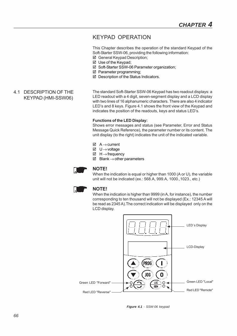
66
KEYPAD OPERATION
This Chapter describes the operation of the standard Keypad of theSoft-Starter SSW-06, providing the following information: General Keypad Description; Use of the Keypad; Soft-Starter SSW-06 Parameter organization; Parameter programming; Description of the Status Indicators.
The standard Soft-Starter SSW-06 Keypad has two readout displays: aLED readout with a 4 digit, seven-segment display and a LCD displaywith two lines of 16 alphanumeric characters. There are also 4 indicatorLED’s and 8 keys. Figure 4.1 shows the front view of the Keypad andindicates the position of the readouts, keys and status LED’s.
Functions of the LED Display:Shows error messages and status (see Parameter, Error and StatusMessage Quick Reference), the parameter number or its content. Theunit display (to the right) indicates the unit of the indicated variable.
A → current U → voltage H → frequency Blank → other parameters
NOTE!When the indication is equal or higher than 1000 (A or U), the variableunit will not be indicated (ex.: 568.A, 999.A, 1000.,1023., etc.)
NOTE!When the indication is higher than 9999 (in A, for instance), the numbercorresponding to ten thousand will not be displayed (Ex.: 12345 A willbe read as 2345 A).The correct indication will be displayed only on theLCD display.
4.1 DESCRIPTION OF THEKEYPAD (HMI-SSW06)
CHAPTER 4
Figure 4.1 - SSW-06 keypad
Red LED "Remote"
Green LED "Local"
LCD-Display
LED´s Display
Green LED "Forward"
Red LED "Reverse"
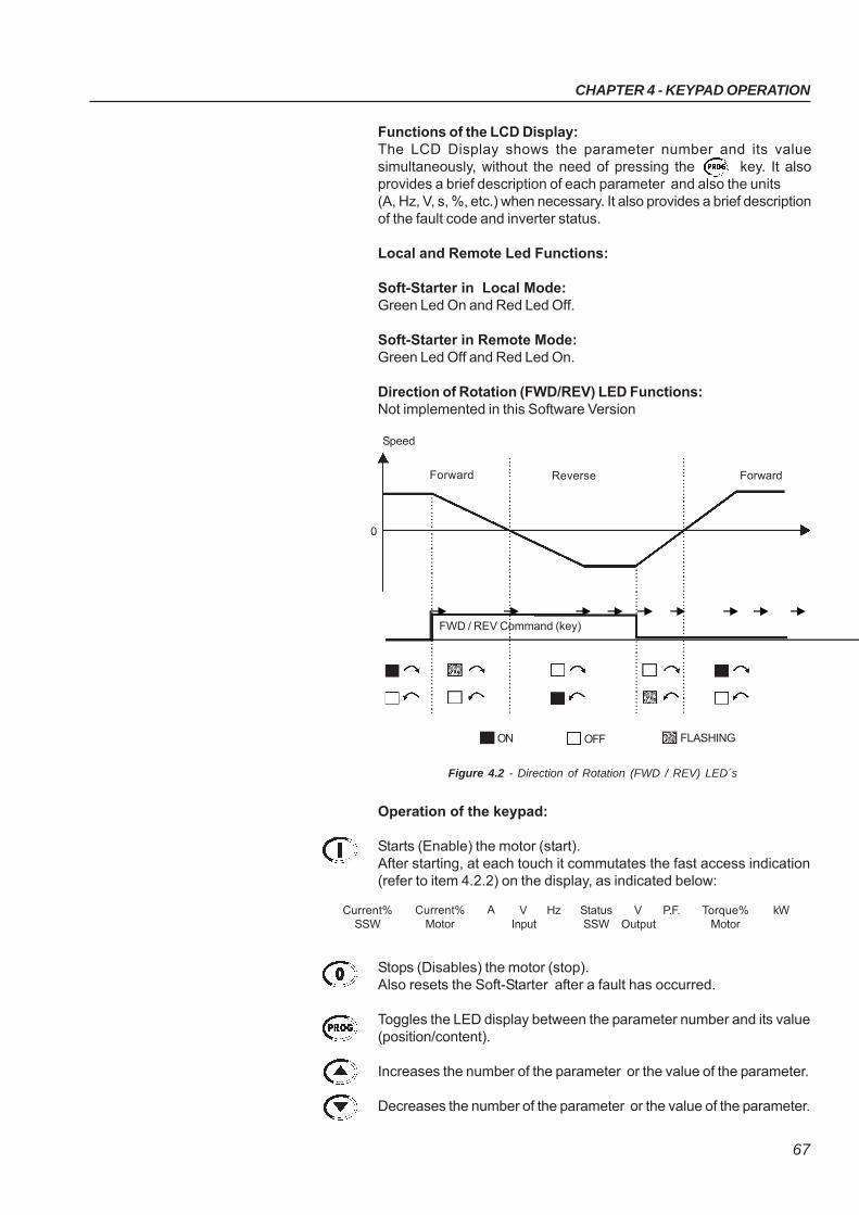
CHAPTER 4 - KEYPAD OPERATION
67
Operation of the keypad:
Starts (Enable) the motor (start).After starting, at each touch it commutates the fast access indication(refer to item 4.2.2) on the display, as indicated below:
Stops (Disables) the motor (stop).Also resets the Soft-Starter after a fault has occurred.
Toggles the LED display between the parameter number and its value(position/content).
Increases the number of the parameter or the value of the parameter.
Decreases the number of the parameter or the value of the parameter.
Functions of the LCD Display:The LCD Display shows the parameter number and its valuesimultaneously, without the need of pressing the key. It alsoprovides a brief description of each parameter and also the units(A, Hz, V, s, %, etc.) when necessary. It also provides a brief descriptionof the fault code and inverter status.
Local and Remote Led Functions:
Soft-Starter in Local Mode:Green Led On and Red Led Off.
Soft-Starter in Remote Mode:Green Led Off and Red Led On.
Direction of Rotation (FWD/REV) LED Functions:Not implemented in this Software Version
Speed
ON OFF FLASHING
ForwardForward Reverse
Figure 4.2 - Direction of Rotation (FWD / REV) LED´s
0
FWD / REV Command (key)
Current%SSW
Current%Motor
A VInput
Hz StatusSSW
P.F.VOutput
Torque%Motor
kW
CHAPTER 4 - KEYPAD OPERATION
68
The keypad is used for programming and operating the Soft-Starterallowing the following functions:
Indication of the Soft-Starter SSW-06 status and main operationvariables;
Fault indications; Viewing and programming of the setable parameters; Soft-Starter SSW-06 operation (via keys , and ).
4.2 USE OF THE KEYPAD
4.2.1 Keypad use forSoft-Starter SSW-06Operation
Al the functions related to the SSW-06 Soft-Starter operation (Start,Stop, Increment, Decrement, FWD/REV, JOG, Local/Remote situationcommutation) can be performed through the keypad. All keypad areenabled when the Local Mode has been selected. All these functionscan be executed individually through digital inputs. For this, all parametersrelated to these functions and to the corresponding inputs must beprogrammed.
Operation of the keypad:
When programmed (P220 = 2 or 3), it selects the command source,changing between "Local” and “Remote”.
When programmed (P229 = 0 (key , → “ Local” condition)
and/or P230 = 0 ( key , → “Remote” condition)).
Starts the motor via Acceleration Ramp. (motor accelerates accordingto acceleration ramp and load characteristics).
Stops the motor via Deceleration Ramp. (motor decelerates accordingto deceleration ramp and stops).It resets the Soft-Starter after a fault trip (always active).
Reverses the motor direction of rotation.Enabled when P220 = 2 (Keypad LOC), P229 = 0 (HMI Key), LocalMode, P231 = 1 (By Contactor) or P231 = 2 (JOG Only).Enabled when P220 = 3 (Keypad REM), P230 = 0 (HMI Key), RemoteMode, P231 = 1 (By Contactor) or P231 = 2 (JOG Only).
When P231 = 1 (By Contactor), changes the motor direction of rotationvia contactor, if the contactors are connected at the input power supplyand P277 = 4 (FWD/REV-K1) and P278 = 4 (FWD/REV-K2).When P231 = 2 (JOG Only), changes the motor direction of rotationonly by the Jog function. Contactors are not required.
Enabled when P510 = 1 (Active).When the Jog key is pressed, it accelerates the motor to the Jogfrequency conforming to the motor direction of rotation. When the Jogkey is released, the motor decelerates and stops.
The motor must be disabled and the Soft-Starter SSW-06 must have aGeneral Enable.
Reverses the direction of motor rotation between Forward/Reverse.
Toggles between LOCAL or REMOTE modes of operation.
Performs the JOG function when pressed. Any DIx programmed forGeneral Enable must be closed (and the SSW-06 must be stopped) toenable JOG function.
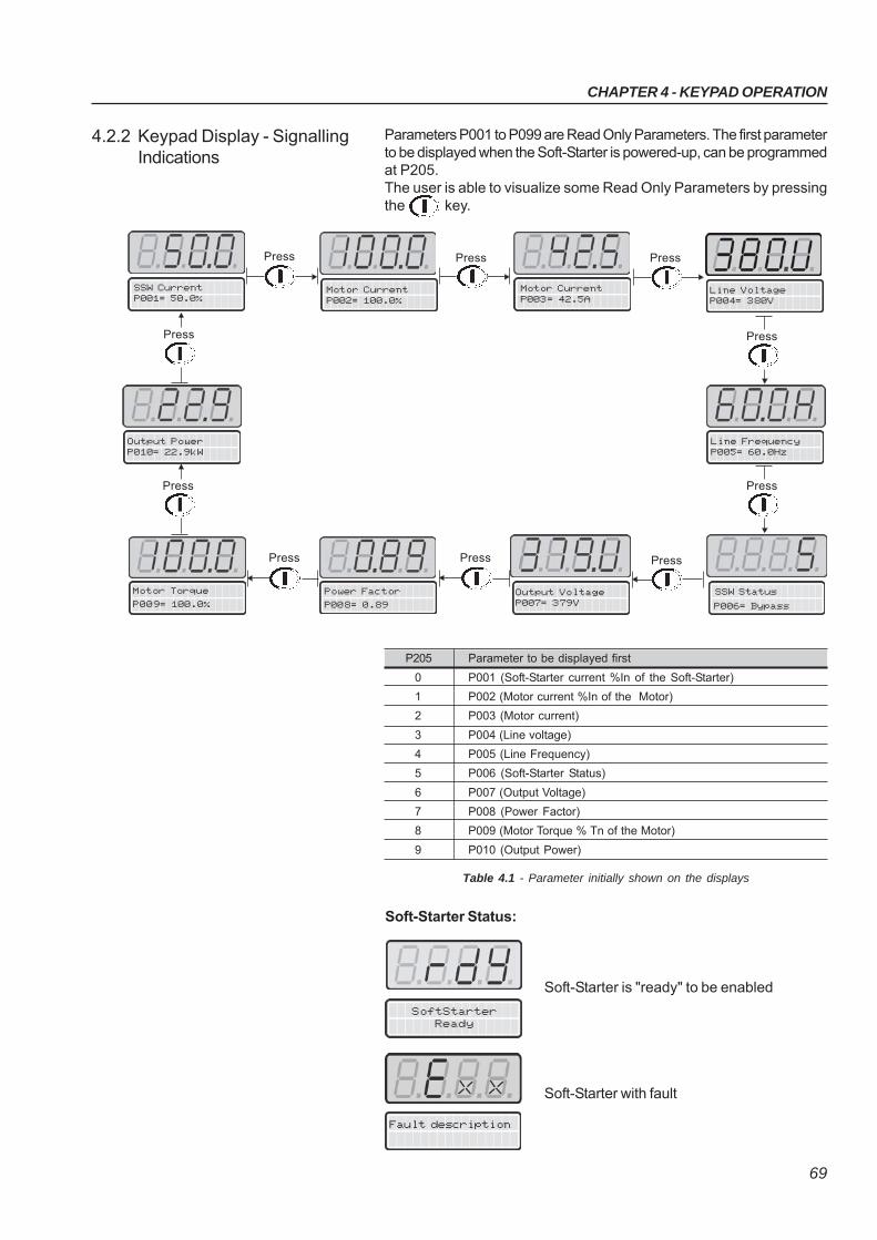
CHAPTER 4 - KEYPAD OPERATION
69
SoftStarterReady
Soft-Starter Status:
Soft-Starter is "ready" to be enabled
Soft-Starter with fault
Parameters P001 to P099 are Read Only Parameters. The first parameterto be displayed when the Soft-Starter is powered-up, can be programmedat P205.The user is able to visualize some Read Only Parameters by pressingthe key.
4.2.2 Keypad Display - SignallingIndications
P205 Parameter to be displayed first
0 P001 (Soft-Starter current %In of the Soft-Starter)
1 P002 (Motor current %In of the Motor)
2 P003 (Motor current)
3 P004 (Line voltage)
4 P005 (Line Frequency)
5 P006 (Soft-Starter Status)
6 P007 (Output Voltage)
7 P008 (Power Factor)
8 P009 (Motor Torque % Tn of the Motor)
9 P010 (Output Power)
Table 4.1 - Parameter initially shown on the displays
Motor Current P002= 100.0%
Motor Current P003= 42.5A
Power Factor
P008= 0.89
Motor Torque
P009= 100.0%
Output VoltageP007= 379V
Press Press Press
Line VoltageP004= 380V
PressPressPress
SSW Current P001= 50.0%
SSW Status
P006= Bypass
Line FrequencyP005= 60.0Hz
Press
Press
Output PowerP010= 22.9kW
Press
Press
Fault description
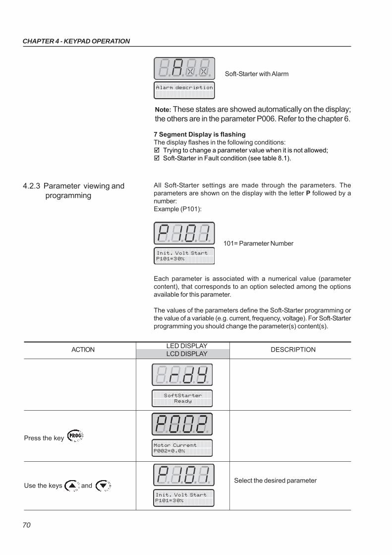
CHAPTER 4 - KEYPAD OPERATION
70
7 Segment Display is flashingThe display flashes in the following conditions: Trying to change a parameter value when it is not allowed; Soft-Starter in Fault condition (see table 8.1).
All Soft-Starter settings are made through the parameters. Theparameters are shown on the display with the letter P followed by anumber:Example (P101):
4.2.3 Parameter viewing andprogramming
Init. Volt StartP101=30%
101= Parameter Number
Each parameter is associated with a numerical value (parametercontent), that corresponds to an option selected among the optionsavailable for this parameter.
The values of the parameters define the Soft-Starter programming orthe value of a variable (e.g. current, frequency, voltage). For Soft-Starterprogramming you should change the parameter(s) content(s).
Press the key
Use the keys and
ACTIONLED DISPLAY
DESCRIPTIONLCD DISPLAY
SoftStarterReady
Motor CurrentP002=0.0%
Init. Volt StartP101=30%
Select the desired parameter
Alarm description
Soft-Starter with Alarm
Note: These states are showed automatically on the display;the others are in the parameter P006. Refer to the chapter 6.
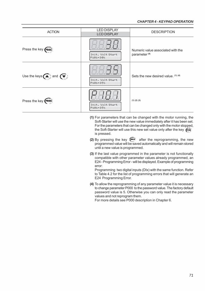
CHAPTER 4 - KEYPAD OPERATION
71
Press the key
Use the keys and
Press the key
ACTIONLED DISPLAY
DESCRIPTIONLCD DISPLAY
Numeric value associated with theparameter (4)
Sets the new desired value. (1) (4)
(1) (2) (3)
Init. Volt StartP101=30%
Init. Volt StartP101=35%
(1) For parameters that can be changed with the motor running, theSoft-Starter will use the new value immediately after it has been set.For the parameters that can be changed only with the motor stopped,the Soft-Starter will use this new set value only after the keyis pressed.
(2) By pressing the key after the reprogramming, the newprogrammed value will be saved automatically and will remain storeduntil a new value is programmed.
(3) If the last value programmed in the parameter is not functionallycompatible with other parameter values already programmed, anE24 - Programming Error - will be displayed. Example of programmingerror:Programming two digital inputs (DIx) with the same function. Referto Table 4.2 for the list of programming errors that will generate anE24 Programming Error.
(4) To allow the reprogramming of any parameter value it is necessaryto change parameter P000 to the password value. The factory defaultpassword value is 5. Otherwise you can only read the parametervalues and not reprogram them.For more details see P000 description in Chapter 6.
Init. Volt StartP101=35%
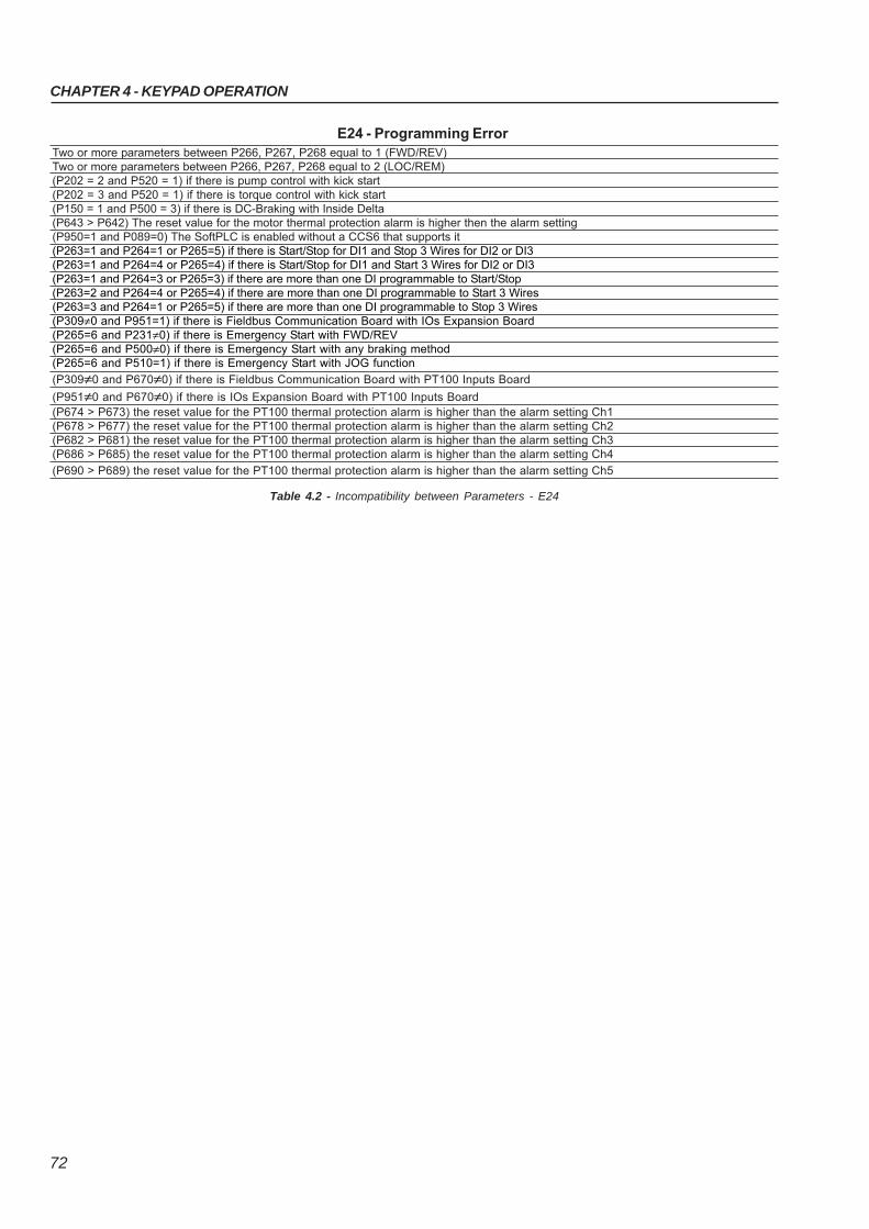
CHAPTER 4 - KEYPAD OPERATION
72
Two or more parameters between P266, P267, P268 equal to 1 (FWD/REV)Two or more parameters between P266, P267, P268 equal to 2 (LOC/REM)(P202 = 2 and P520 = 1) if there is pump control with kick start(P202 = 3 and P520 = 1) if there is torque control with kick start(P150 = 1 and P500 = 3) if there is DC-Braking with Inside Delta(P643 > P642) The reset value for the motor thermal protection alarm is higher then the alarm setting(P950=1 and P089=0) The SoftPLC is enabled without a CCS6 that supports it(P263=1 and P264=1 or P265=5) if there is Start/Stop for DI1 and Stop 3 Wires for DI2 or DI3(P263=1 and P264=4 or P265=4) if there is Start/Stop for DI1 and Start 3 Wires for DI2 or DI3(P263=1 and P264=3 or P265=3) if there are more than one DI programmable to Start/Stop(P263=2 and P264=4 or P265=4) if there are more than one DI programmable to Start 3 Wires(P263=3 and P264=1 or P265=5) if there are more than one DI programmable to Stop 3 Wires(P309≠0 and P951=1) if there is Fieldbus Communication Board with IOs Expansion Board(P265=6 and P231≠0) if there is Emergency Start with FWD/REV(P265=6 and P500≠0) if there is Emergency Start with any braking method(P265=6 and P510=1) if there is Emergency Start with JOG function
(P309≠0 and P670≠0) if there is Fieldbus Communication Board with PT100 Inputs Board
(P951≠0 and P670≠0) if there is IOs Expansion Board with PT100 Inputs Board(P674 > P673) the reset value for the PT100 thermal protection alarm is higher than the alarm setting Ch1(P678 > P677) the reset value for the PT100 thermal protection alarm is higher than the alarm setting Ch2(P682 > P681) the reset value for the PT100 thermal protection alarm is higher than the alarm setting Ch3(P686 > P685) the reset value for the PT100 thermal protection alarm is higher than the alarm setting Ch4
(P690 > P689) the reset value for the PT100 thermal protection alarm is higher than the alarm setting Ch5
E24 - Programming Error
Table 4.2 - Incompatibility between Parameters - E24
73
The Soft-Starter SSW-06 shall be installed according to Chapter 3 -Installation and Connection. If the drive project is different from the typicalrecommended drives, the steps below may also be followed.
DANGER!Disconnect the AC input power before making any connections.
1) Check all connections:Check if the power, grounding and control connections are correctand well tightened.
2) Clean the inside of the Soft-Starter SSW-06:Remove all shipping material from the inside of the Soft-StarterSSW-06 or cabinet.
3) Check the correct voltage selection:In models 255A to 820A, the fan supply voltage selection is correct.In models 950A to 1400A the single-phase supply voltage must bechecked to make sure it is adequate for the voltage of the fans.
4) Check the motor:Check all motor connections and verify if their voltages, currentsand frequencies match the Soft-Starter SSW-06 specifications.
5) Check the Soft-Starter SSW-06 motor connection type:Check if the standard three-wire connection should be used or if theSoft-Starter SSW-06 should be connected via inside delta of themotor. For more details, refer to Chapter 3.
6) Uncouple the load from the motor:If the motor cannot be uncoupled, make sure that the direction ofrotation (FWD/REV) cannot cause damage to the machine.
7) Close the Soft-Starter SSW-06 and/or cabinet cover.
START-UP
This Chapter provides the following information: How to check and prepare the Soft-Starter SSW-06 before power-up; How to power-up and check for proper operation; How to operate the Soft-Starter SSW-06 (See Electrical Installation).
5.1 POWER-UPPREPARATION
CHAPTER 5
CHAPTER 5 - START-UP
74
5.2 INITIAL POWER-UP(required parameter settings)
After the Soft-Starter SSW-06 has been checked, AC power can beapplied:
1) Check the supply voltage:Measure the line voltage and check if it is within the specified range(Nominal Voltage -15% to +10%).
2) Power-up the Electronics Supply.
NOTE!Always energize the electronics supply before energizing the powerand execute all adjustments/settings described in this item.
3) Check if the power-up has been successfulWhen the Soft-Starter SSW-06 is powered up for the first time orwhen the factory default parameter values are loaded (P204 = 5), astart-up routine is run.This routine requests the user to program some basic parametersto ensure proper Soft-Starter SSW-06 operation and motor operation.This routine sequence changes according to the selected type ofcontrol. For more details about the control type to be selected, referto Parameter P202 in Chapter 6.The parameterization sequence for each control type is show infigure 5.1.
ATTENTION!For correct programming of the protection parameters, please considerthe catalog data and the motor nameplate data of the used motor.
To protect the motor against overloads during the start process andduring operation, program the thermal class of the motor. For moredetails about programming of the Thermal Class, see description ofParameter P640 in Chapter 6.
In this parameter setting sequence only the main parameters for learningabout the Soft-Starter SSW-06 operation are shown. Please programall necessary parameters for correct operation of the Soft-Starter andmotor protection, before operating it at nominal operation conditions.
4) Close the input circuit-breaker.
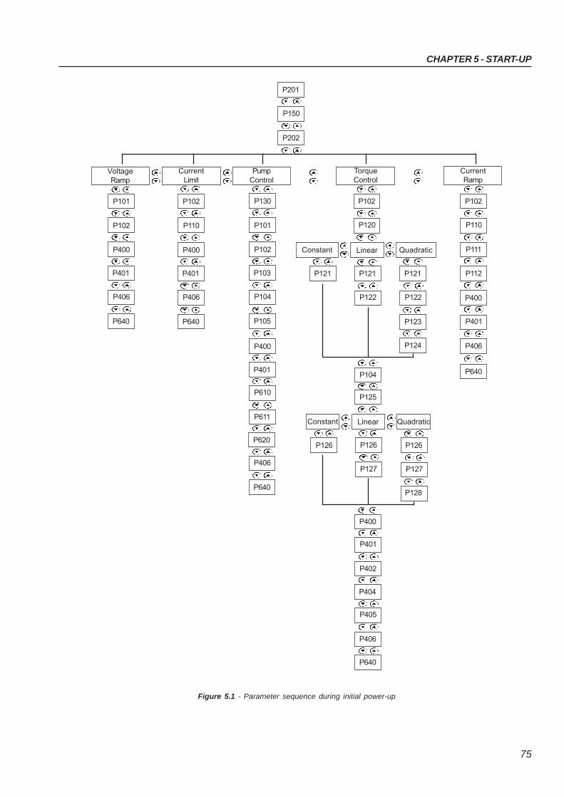
CHAPTER 5 - START-UP
75
Figure 5.1 - Parameter sequence during initial power-up
P611
P610
P401
P400
P102
P101
VoltageRamp
CurrentLimit
P202
P150
P201
PumpControl
P640
P406
P401
P400
P110
P102
P105
P104
P103
P102
P101
P130
P640
P406
P401
P400
P640
P406
P620
TorqueControl
CurrentRamp
P120
P102
Constant Linear Quadratic
P123
P122
P121
P122
P121P121
P124
Constant Linear Quadratic
P128
P127
P126
P127
P126P126
P402
P401
P400
P406
P405
P404
P640
P104
P125
P111
P110
P102
P112
P406
P401
P400
P640
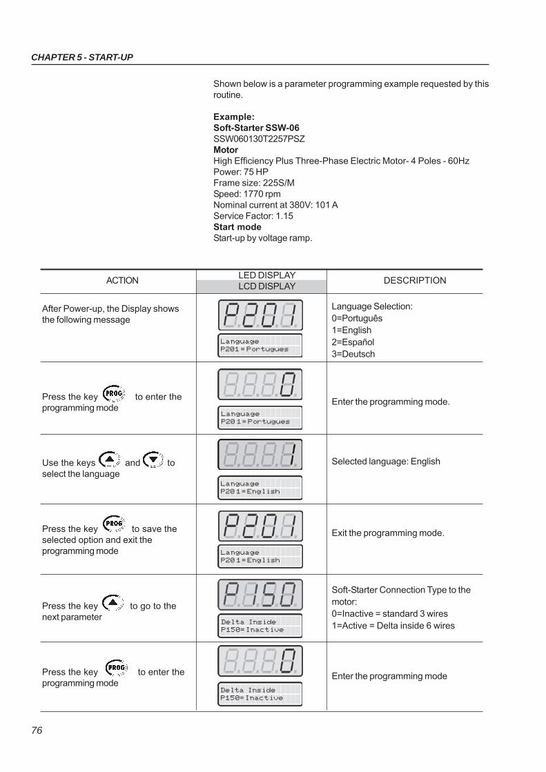
CHAPTER 5 - START-UP
76
Shown below is a parameter programming example requested by thisroutine.
Example:Soft-Starter SSW-06SSW060130T2257PSZMotorHigh Efficiency Plus Three-Phase Electric Motor- 4 Poles - 60HzPower: 75 HPFrame size: 225S/MSpeed: 1770 rpmNominal current at 380V: 101 AService Factor: 1.15Start modeStart-up by voltage ramp.
LanguageP201 = Portugues
LanguageP20 1 = Portugues
LanguageP20 1 = English
LanguageP20 1 = English
Delta InsideP150=Inactive
After Power-up, the Display showsthe following message
Press the key to enter theprogramming mode
Use the keys and toselect the language
Press the key to save theselected option and exit theprogramming mode
Press the key to go to thenext parameter
Press the key to enter theprogramming mode
ACTIONLED DISPLAY
DESCRIPTIONLCD DISPLAY
Language Selection:0=Português1=English2=Español3=Deutsch
Enter the programming mode.
Selected language: English
Exit the programming mode.
Soft-Starter Connection Type to themotor:0=Inactive = standard 3 wires1=Active = Delta inside 6 wires
Enter the programming mode
Delta InsideP150=Inactive
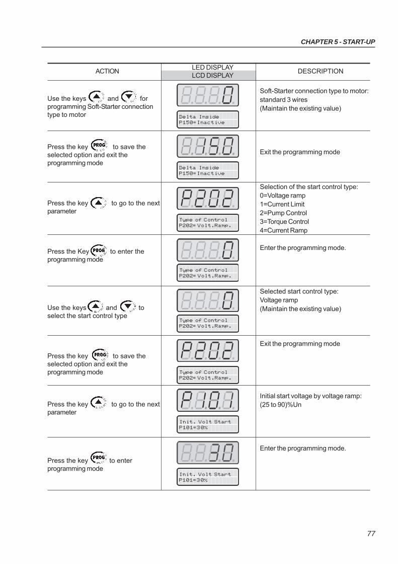
CHAPTER 5 - START-UP
77
Type of ControlP202= Volt.Ramp.
Type of ControlP202= Volt.Ramp.
Use the keys and forprogramming Soft-Starter connectiontype to motor
Press the key to save theselected option and exit theprogramming mode
Press the key to go to the nextparameter
Press the Key to enter theprogramming mode
Use the keys and toselect the start control type
Press the key to save theselected option and exit theprogramming mode
Press the key to go to the nextparameter
Press the key to enterprogramming mode
ACTIONLED DISPLAY
DESCRIPTIONLCD DISPLAY
Soft-Starter connection type to motor:standard 3 wires(Maintain the existing value)
Exit the programming mode
Selection of the start control type:0=Voltage ramp1=Current Limit2=Pump Control3=Torque Control4=Current Ramp
Enter the programming mode.
Selected start control type:Voltage ramp(Maintain the existing value)
Exit the programming mode
Initial start voltage by voltage ramp:(25 to 90)%Un
Enter the programming mode.
Delta InsideP150=Inactive
Delta InsideP150=Inactive
Type of ControlP202= Volt.Ramp.
Type of ControlP202= Volt.Ramp.
Init. Volt StartP101=30%
Init. Volt StartP101=30%
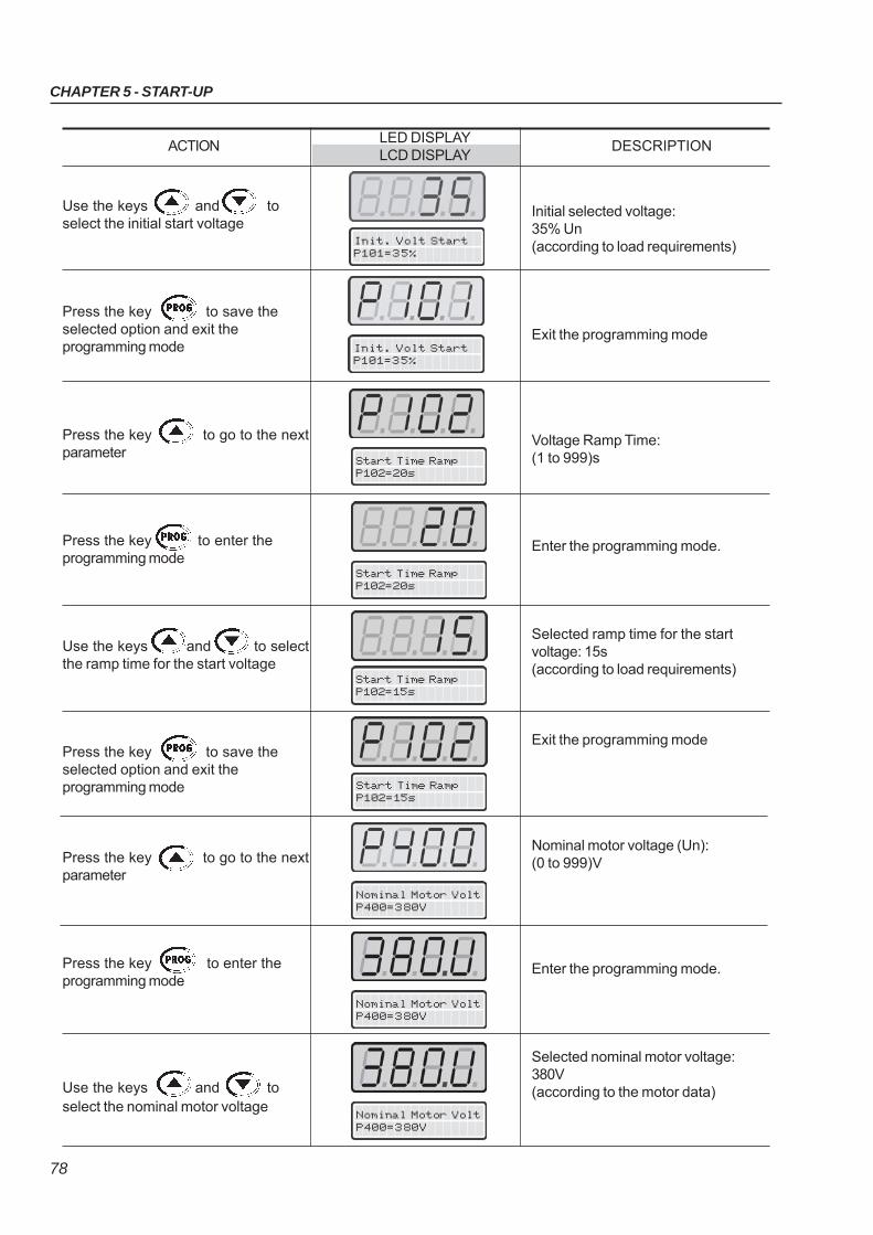
CHAPTER 5 - START-UP
78
Start Time RampP102=20s
Start Time RampP102=15s
Use the keys and toselect the initial start voltage
Press the key to save theselected option and exit theprogramming mode
Press the key to go to the nextparameter
Press the key to enter theprogramming mode
Use the keys and to selectthe ramp time for the start voltage
Press the key to save theselected option and exit theprogramming mode
Press the key to go to the nextparameter
Press the key to enter theprogramming mode
Use the keys and toselect the nominal motor voltage
ACTIONLED DISPLAY
DESCRIPTIONLCD DISPLAY
Init. Volt StartP101=35%
Start Time RampP102=20s
Start Time RampP102=15s
Nominal Motor VoltP400=380V
Nominal Motor VoltP400=380V
Nominal Motor VoltP400=380V
Initial selected voltage:35% Un(according to load requirements)
Exit the programming mode
Voltage Ramp Time:(1 to 999)s
Enter the programming mode.
Selected ramp time for the startvoltage: 15s(according to load requirements)
Exit the programming mode
Nominal motor voltage (Un):(0 to 999)V
Enter the programming mode.
Selected nominal motor voltage:380V(according to the motor data)
Init. Volt StartP101=35%
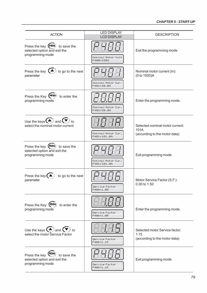
CHAPTER 5 - START-UP
79
ACTIONLED DISPLAY
DESCRIPTIONLCD DISPLAY
Nominal Motor Cur.P401=101.0A
Nominal Motor Cur.P401=101.0A
Press the key to save theselected option and exit theprogramming mode
Press the key to go to the nextparameter
Press the Key to enter theprogramming mode
Use the keys and toselect the nominal motor current
Press the key to save theselected option and exit theprogramming mode
Press the key to go to the nextparameter
Press the Key to enter theprogramming mode
Use the keys and toselect the motor Service Factor
Press the key to save theselected option and exit theprogramming mode
Exit the programming mode
Nominal motor current (In):(0 to 1500)A
Enter the programming mode.
Selected nominal motor current:101A(according to the motor data)
Exit programming mode
Motor Service Factor (S.F.):0.00 to 1.50
Enter the programming mode.
Selected motor Service factor:1.15(according to the motor data)
Exit programming mode
Nominal Motor Cur.P401=20.0A
Nominal Motor Cur.P401=20.0A
Service FactorP406=1.00
Service FactorP406=1.00
Service FactorP406=1.15
Service FactorP406=1.15
Nominal Motor VoltP400=380V
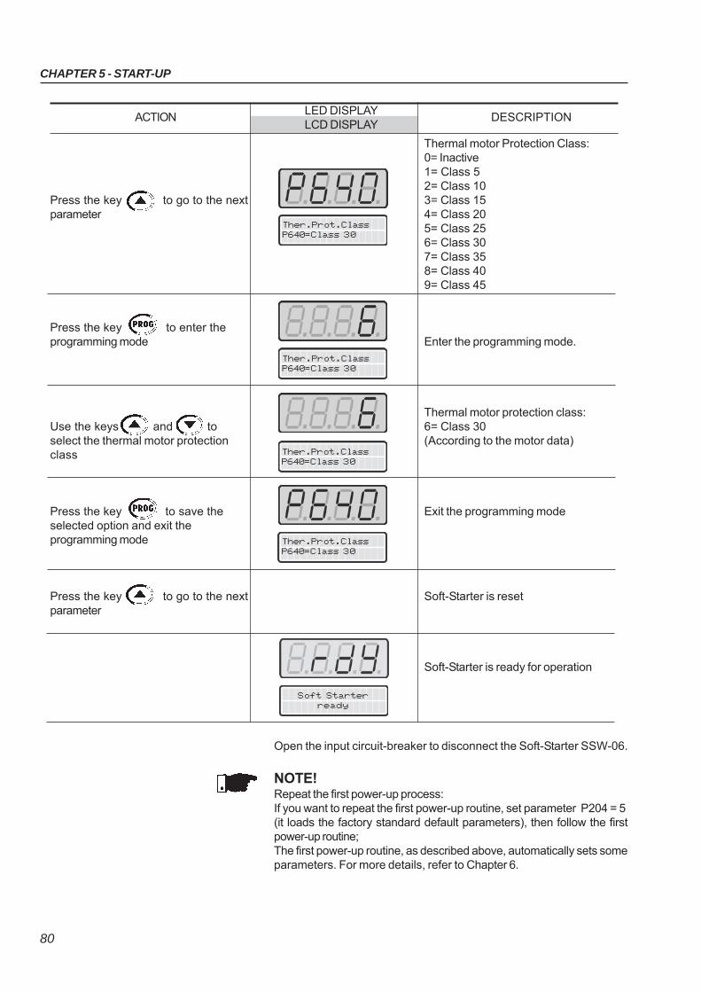
CHAPTER 5 - START-UP
80
Press the key to go to the nextparameter
Press the key to enter theprogramming mode
Use the keys and toselect the thermal motor protectionclass
Press the key to save theselected option and exit theprogramming mode
Press the key to go to the nextparameter
ACTIONLED DISPLAY
DESCRIPTIONLCD DISPLAY
Thermal motor Protection Class:0= Inactive1= Class 52= Class 103= Class 154= Class 205= Class 256= Class 307= Class 358= Class 409= Class 45
Enter the programming mode.
Thermal motor protection class:6= Class 30(According to the motor data)
Exit the programming mode
Soft-Starter is reset
Soft-Starter is ready for operation
Soft Starterready
Open the input circuit-breaker to disconnect the Soft-Starter SSW-06.
NOTE!Repeat the first power-up process:If you want to repeat the first power-up routine, set parameter P204 = 5(it loads the factory standard default parameters), then follow the firstpower-up routine;The first power-up routine, as described above, automatically sets someparameters. For more details, refer to Chapter 6.
Ther.Prot.ClassP640=Class 30
Ther.Prot.ClassP640=Class 30
Ther.Prot.ClassP640=Class 30
Ther.Prot.ClassP640=Class 30
CHAPTER 5 - START-UP
81
5.3 START-UP This Section describes the start-up procedure when operating via theKeypad. Five types of control will be considered:
Start-up by Voltage Ramp:The start by voltage ramp is the most used method and its programmingand parameter setting is very easy to do. The Soft-Starter SSW-06applies the voltage to the motor without any feedback of the voltage orcurrent applied to the motor.
Start-up by Current Limit:The maximum programmed current level is maintained during start-upand it is set according to the application requirements. This programmingis very easy.
Start-up by Current Ramp:The maximum current level is also limited during the start-up, howeverhigher or lower start-up current limits can be set.
Start-up by Pump Control:Optimized control method, providing the required torque to start/stophydraulic centrifugal pumps smoothly.
Start-up by Torque Control:The Soft-Starter SSW-06 is fitted with a torque control algorithm of highperformance and is totally flexible to meet any application requirementduring the motor start or stop and its coupled load.The method allows a torque control with 1 setting point, a torque controlwith 2 setting points and a torque control with 3 setting points.
NOTE!Every time the content of the Parameter P202 is changed, the Soft-Starter will execute a setting sequence routine according to the selectedcontrol type.For more details, refer to Parameter P202 in Chapter 6 and 7.
The following sequence is valid for Drive 1 (see item 3.3.1). The SSW-06Soft-Starter must already be installed and the electronics, fans andpower must already be energized, according to chapter 3, with thesetting sequence of the initial Start-up complete, as described in theItem 5.2.
5.3.1 Start-up: Operation via Keypad Type of control: Voltage Ramp
Power-up the Soft-Starter
Press the key . Press the key
to find P000. Also the key
may be used to find Parameter P000
ACTIONLED DISPLAY
DESCRIPTIONLCD DISPLAY
Soft-Starter is ready to be operated
It enables the access for changingparameters. With setting according toFactory Default [P200 = 1 (Password isactive)], you must set P000 = 5 forchanging the parameter content.
Parameter AccessP000=0
Soft Starterready
CHAPTER 5 - START-UP
82
Press the key to enter theprogramming mode
Use the Keys and toprogram the Password value
Press the key to save theselected option and exit theprogramming mode
Press the key to find P202.
Also the key may be used tofind Parameter P202
Press the Key to enter theprogramming mode
Use the keys and toselect the correct value of the ControlType
Press the key to save theselected option and exit theprogramming mode
Press the key and maintain itdepressed to find P003
ACTIONLED DISPLAY
DESCRIPTIONLCD DISPLAY
Enter the Programming Mode
Password value(Factory Default)
Exit the programming mode
This Parameter defines the Type ofControl0=Voltage Ramp1=Current Limit2=Pump Control3=Torque Control4=Current Ramp
Enter the Programming Mode
Type of Control selected for theStart-up: Voltage Ramp(maintain the existing value)
Exit the programming mode
Motor Current (A)
Type of ControlP202=Volt. Ramp.
Parameter AccessP000=5
Parameter AccessP000=5
Type of ControlP202=Volt. Ramp.
Type of ControlP202=Volt. Ramp.
Parameter AccessP000=0
Type of ControlP202=Volt. Ramp.
Motor CurrentP003=0A
CHAPTER 5 - START-UP
83
Press the key
Press the key
Press the key
Press the key
Press the key
Press the key again
ACTIONLED DISPLAY
DESCRIPTIONLCD DISPLAY
This is only a Read Parameter
Motor accelerates and a high value ofcurrent is reached.
Then the current decreases down to avalue required by the load.
Motor decelerates until stopping bycoast to rest. Time to stop depends onload inertia and friction.
Motor accelerates and a high value ofcurrent is reached.
Then the current decreases up to avalue required by the load.
Soft-Starter is now controlled viaterminals (REMOTE). Motordecelerates till stopping by the loadinertia.
Soft-Starter is controlled again viakeypad (LOCAL). Motor remainsstopped.
Motor CurrentP003=0A
Motor CurrentP003=90A
SoftStarterready
Motor CurrentP003=346A
Motor CurrentP003=90A
Motor CurrentP003=346A
SoftStarterready
SoftStarterready
NOTES!Setting hints and suggestions for all types of controls and their usescan be found in Chapter 7.For start-up through voltage ramp refer to Item 7.1.1.
84
DETAILED PARAMETER DESCRIPTION
This Chapter describes in detail all Soft-Starter SSW-06 parameters. In orderto simplify the explanation, the parameters have been grouped by characteristicsand functions:
Symbols and definitions used in the text below:
(1) Indicates that the parameter can only be changed when the Soft-StarterSSW-06 is disabled (motor stopped).
(2) Parameters not changed when programmed to Factory Default (P204=5).
6.1 ACCESS AND READ ONLY PARAMETERS - P000 to P099
This parameter opens the access to change the parameter values.When values are set according to Factory Default [P200 = 1 (Passwordis active)] set P000 = 5 to change parameter values, and thePassword value is equal to 5.
By programming P000 with the password that releases access tochange parameter contents, plus 1 (Password + 1), you will obtainaccess only to the parameters with contents different from the factorysetting.
To change the password to any other value (password 1), proceed asfollows:
(1) Set P000=5 (current password) and P200= 0 (password inactive).
(2) Press the key .
(3) Change P200 to 1 (password active).
(4) Press the key again: display shows P000.
(5) Press the key again: display shows 5 (last password).
(6) Use the keys and to change to the desired password
value (password 1).
(7) Press the key : display shows P000. From this moment on,
the new password becomes active. Thus, to change parametercontent P000 must be set to the new password. (Password 1).
P000 0 to 999Parameter Access [0]Password Value -Setting
Range[Factory Setting]
Parameter Unit Description / Notes
Read Only Parameters Variables that can only be viewed on the display but
not changed by the user.
Regulation Parameters Programmable values used by the Soft-Starter
SSW-06 functions.
Configuration Parameters These Parameters define the Soft-Starter
SSW-06 characteristics, the functions to be executed,
as well as the input/output functions of the control board.
Motor Parameters Motor data that are indicated on the motor nameplate.
Special Function Parameters Here are the parameters related to special functions.
Protection Parameters Here are the parameters related to actuation levels
and actuation time of the motor protection.
CHAPTER 6
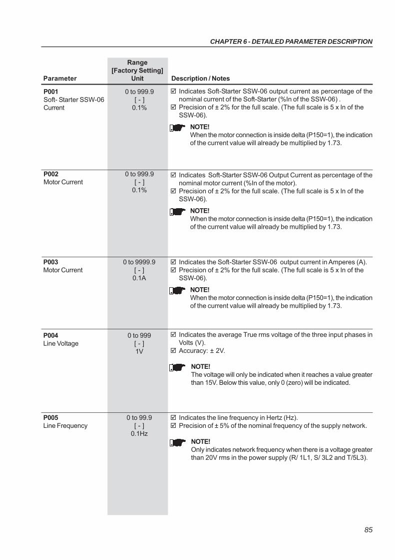
CHAPTER 6 - DETAILED PARAMETER DESCRIPTION
85
Indicates Soft-Starter SSW-06 output current as percentage of thenominal current of the Soft-Starter (%In of the SSW-06) .
Precision of ± 2% for the full scale. (The full scale is 5 x ln of theSSW-06).
NOTE!When the motor connection is inside delta (P150=1), the indicationof the current value will already be multiplied by 1.73.
P001 0 to 999.9Soft- Starter SSW-06 [ - ]Current 0.1%
Range[Factory Setting]
Parameter Unit Description / Notes
Indicates Soft-Starter SSW-06 Output Current as percentage of thenominal motor current (%In of the motor).
Precision of ± 2% for the full scale. (The full scale is 5 x ln of theSSW-06).
NOTE!When the motor connection is inside delta (P150=1), the indicationof the current value will already be multiplied by 1.73.
P002 0 to 999.9Motor Current [ - ]
0.1%
Indicates the Soft-Starter SSW-06 output current in Amperes (A). Precision of ± 2% for the full scale. (The full scale is 5 x ln of the
SSW-06).
NOTE!When the motor connection is inside delta (P150=1), the indicationof the current value will already be multiplied by 1.73.
P003 0 to 9999.9Motor Current [ - ]
0.1A
Indicates the average True rms voltage of the three input phases inVolts (V).
Accuracy: ± 2V.
NOTE!The voltage will only be indicated when it reaches a value greaterthan 15V. Below this value, only 0 (zero) will be indicated.
P004 0 to 999Line Voltage [ - ]
1V
Indicates the line frequency in Hertz (Hz). Precision of ± 5% of the nominal frequency of the supply network.
NOTE!Only indicates network frequency when there is a voltage greaterthan 20V rms in the power supply (R/ 1L1, S/ 3L2 and T/5L3).
P005 0 to 99.9Line Frequency [ - ]
0.1Hz
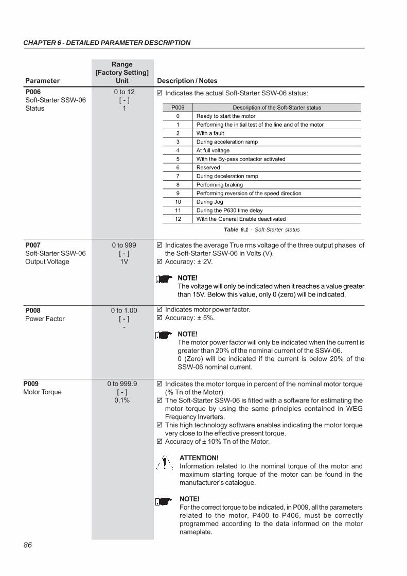
CHAPTER 6 - DETAILED PARAMETER DESCRIPTION
86
Range[Factory Setting]
Parameter Unit Description / Notes
P006 0 to 12Soft-Starter SSW-06 [ - ]Status 1 P006 Description of the Soft-Starter status
0 Ready to start the motor
1 Performing the initial test of the line and of the motor
2 With a fault
3 During acceleration ramp
4 At full voltage
5 With the By-pass contactor activated
6 Reserved
7 During deceleration ramp
8 Performing braking
9 Performing reversion of the speed direction
10 During Jog
11 During the P630 time delay
12 With the General Enable deactivated
Indicates the actual Soft-Starter SSW-06 status:
Table 6.1 - Soft-Starter status
Indicates motor power factor. Accuracy: ± 5%.
NOTE!The motor power factor will only be indicated when the current isgreater than 20% of the nominal current of the SSW-06.0 (Zero) will be indicated if the current is below 20% of theSSW-06 nominal current.
P008 0 to 1.00Power Factor [ - ]
-
Indicates the average True rms voltage of the three output phases ofthe Soft-Starter SSW-06 in Volts (V).
Accuracy: ± 2V.
NOTE!The voltage will only be indicated when it reaches a value greaterthan 15V. Below this value, only 0 (zero) will be indicated.
P007 0 to 999Soft-Starter SSW-06 [ - ]Output Voltage 1V
P009 0 to 999.9Motor Torque [ - ]
0,1%
Indicates the motor torque in percent of the nominal motor torque(% Tn of the Motor).
The Soft-Starter SSW-06 is fitted with a software for estimating themotor torque by using the same principles contained in WEGFrequency Inverters.
This high technology software enables indicating the motor torquevery close to the effective present torque.
Accuracy of ± 10% Tn of the Motor.
ATTENTION!Information related to the nominal torque of the motor andmaximum starting torque of the motor can be found in themanufacturer’s catalogue.
NOTE!For the correct torque to be indicated, in P009, all the parametersrelated to the motor, P400 to P406, must be correctlyprogrammed according to the data informed on the motornameplate.
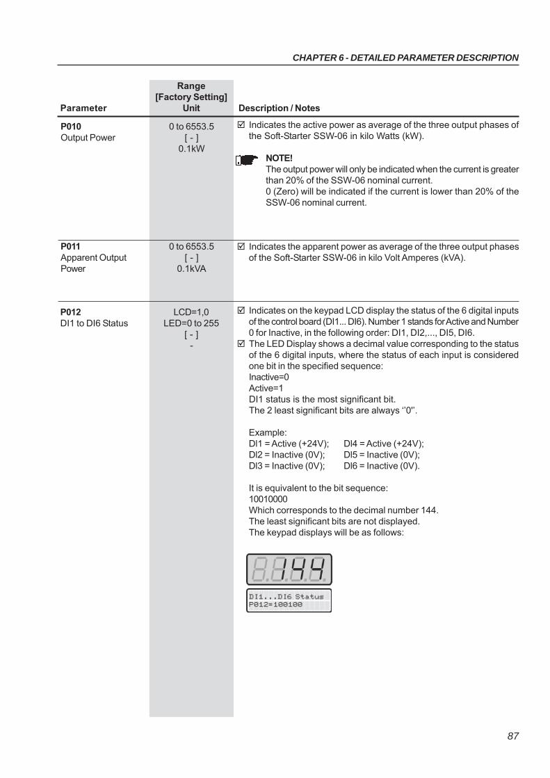
CHAPTER 6 - DETAILED PARAMETER DESCRIPTION
87
Range[Factory Setting]
Parameter Unit Description / Notes
Indicates the active power as average of the three output phases ofthe Soft-Starter SSW-06 in kilo Watts (kW).
NOTE!The output power will only be indicated when the current is greaterthan 20% of the SSW-06 nominal current.0 (Zero) will be indicated if the current is lower than 20% of theSSW-06 nominal current.
P010 0 to 6553.5Output Power [ - ]
0.1kW
Indicates the apparent power as average of the three output phasesof the Soft-Starter SSW-06 in kilo Volt Amperes (kVA).
P011 0 to 6553.5Apparent Output [ - ]Power 0.1kVA
DI1...DI6 StatusP012=100100
Indicates on the keypad LCD display the status of the 6 digital inputsof the control board (DI1... DI6). Number 1 stands for Active and Number0 for Inactive, in the following order: DI1, DI2,..., DI5, DI6.
The LED Display shows a decimal value corresponding to the statusof the 6 digital inputs, where the status of each input is consideredone bit in the specified sequence:Inactive=0Active=1DI1 status is the most significant bit.The 2 least significant bits are always ‘’0'’.
Example:Dl1 = Active (+24V); Dl4 = Active (+24V);Dl2 = Inactive (0V); Dl5 = Inactive (0V);Dl3 = Inactive (0V); Dl6 = Inactive (0V).
It is equivalent to the bit sequence:10010000Which corresponds to the decimal number 144.The least significant bits are not displayed.The keypad displays will be as follows:
P012 LCD=1,0DI1 to DI6 Status LED=0 to 255
[ - ]-
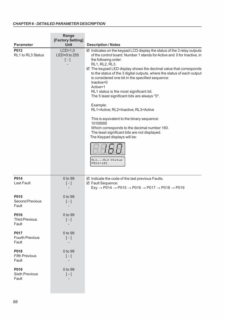
CHAPTER 6 - DETAILED PARAMETER DESCRIPTION
88
Range[Factory Setting]
Parameter Unit Description / Notes
RL1...RL3 StatusP013=101
Indicates on the keypad LCD display the status of the 3 relay outputsof the control board. Number 1 stands for Active and 0 for Inactive, inthe following order:RL1, RL2, RL3.
The keypad LED display shows the decimal value that correspondsto the status of the 3 digital outputs, where the status of each outputis considered one bit in the specified sequence:Inactive=0Active=1RL1 status is the most significant bit.The 5 least significant bits are always "0".
Example:RL1=Active; RL2=Inactive; RL3=Active
This is equivalent to the binary sequence:10100000Which corresponds to the decimal number 160.The least significant bits are not displayed.
The Keypad displays will be:
P013 LCD=1,0RL1 to RL3 Status LED=0 to 255
[ - ]-
Indicate the code of the last previous Faults. Fault Sequence:
Exy → P014 → P015 → P016 → P017 → P018 → P019
P014 0 to 99Last Fault [ - ]
-
P015 0 to 99Second Previous [ - ]Fault -
P016 0 to 99Third Previous [ - ]Fault -
P017 0 to 99Fourth Previous [ - ]Fault -
P018 0 to 99Fifth Previous [ - ]Fault -
P019 0 to 99Sixth Previous [ - ]Fault -
CHAPTER 6 - DETAILED PARAMETER DESCRIPTION
89
Range[Factory Setting]
Parameter Unit Description / Notes
Indicates the software version contained in the microcontroller memoryof the control board.
P023 X.XXSoftware Version [ - ]
-
P020 0 to 99Current Fault [ - ]
-
It indicates if any fault is active.
NOTE!Erros related to communication (E28, E29 and E30) are notindicated in P020.
P021 0 to 99Current Alarm [ - ]
-
It indicates if any alarm is active.
It indicates the analog output AO1 value directly in “mV”.P027 0 to 10.000Analog Output AO1 [ - ]Value 0.001V
It indicates the analog output AO2 value directly in “mA”.P028 0 to 20.000Analog Output AO2 orValue 4.000 to 20.000
[ - ]0.001mA
Accuracy: ± 2% for full scale (full scale is 5 x In of the SSW-06).
NOTE!When the inside delta connection of the motor is used (P150=1),the indication of the current value will already be multiplied by1.73.
P030 0 to 9999.9Current of Phase R [ - ]
0.1A
P031 0 to 9999.9Current of Phase S [ - ]
0.1A
P032 0 to 9999.9Current of Phase T [ - ]
0.1A
P033 0 to 999Line Voltage - R-S [ - ]
1V
P034 0 to 999Line Voltage - S-T [ - ]
1V
P035 0 to 999Line Voltage - T-R [ - ]
1V
Accuracy: ± 2V.
NOTE!The voltage will only be indicated when it reaches a value greaterthan 15V. Below this value, only 0 (zero) will be indicated.
CHAPTER 6 - DETAILED PARAMETER DESCRIPTION
90
P043 0 to 6553.5Time Enabled [ - ]
0.1h
Indicates the total number of hours that the Soft-Starter has run. This value remains stored even when the Soft-Starter is turned OFF. Indicates up to 6553,5 hours, rolls over to 0000. If P204 is set to 3, P043 is reset to zero.
Range[Factory Setting]
Parameter Unit Description / Notes
Indicates the total number of hours that the Soft-Starter was powered. This value remains stored even when the Soft-Starter is switched
OFF.
NOTE!The indication on the LED display was modified and is differentfrom the previous software versions, following now the standarddescribed in the item 4.1.
P042 0 to 65535Time Powered [ - ]
1h
Indicates the energy consumed by the motor, in kWh. Indicates up to 999.9kWh, then it returns to zero. If P204 is set to 3, P044 is reset to zero. This value remains stored even when the Soft-Starter is turned OFF.
Indicates the energy consumed by the motor, in MWh. Indicates up to 9999MWh, then it returns to zero. If P204 is set to 3, P045 is reset to zero. This value remains stored even when the Soft-Starter is turned OFF.
P044 0 to 999.9kWh Counter [ - ]
1kWh
P045 0 to 9999MWh Counter [ - ]
1MWh
It stores the value of the maximum current during the start. The value of P047 is reset at the beginning of each start. If P204 is set to 3, P047 is reset to zero. This value is not kept when the Soft-Starter is turned OFF. It does not record currents of the JOG function.
It stores the value of the average current during the start. The value of P048 is reset at the beginning of each start. P204 is set to 3, P048 is reset to zero. This value is not kept when the Soft-Starter is turned OFF. It does not record currents of the JOG function.
P047 0 to 9999.9Maximum Starting [ - ]Current 0.1A
P048 0 to 9999.9Average Starting [ - ]Current 0.1A
It stores the real starting time. The real starting time is the time required for the motor to reach its
nominal speed. The real starting time depends on the starting parameters settings
and on the load conditions. The time set in P102, even for voltageramp, is not the real starting time. A motor without load, for instance,
P049 0 to 999Real Starting Time [ - ]
1s
CHAPTER 6 - DETAILED PARAMETER DESCRIPTION
91
Indication of the state of motor thermal protection on a scale of 0% to250%. 250 being the thermal protection functioning point of the mo-tor, indicating an error.
The value indicated in this parameter depends on the motor workingcondition and how long it has been in this condition, for example:stopped, starting or in full operation. The value also depends on theselected thermal class, the nominal power and the service factor of themotor.
A value of approximately 160 can be read if the motor is operating infull load for over 2 hours with a current equal to the nominal currenttimes the service factor (In x S.F. @ 2h).
If P204 is set to 3, P050 is reset to zero. This value remains stored even when the Soft-Starter is turned OFF.
P050 0 to 250Motor Thermal [ - ]Protection Status 1%
Range[Factory Setting]
Parameter Unit Description / Notes
can reach its nominal speed with low voltages. And the time adjustedin P102 is the time in which the Soft-Starter applies 100% of the linevoltage to the motor.
The value of P049 is reset at the beginning of each start. If P204 is set to 3, P049 is reset to zero. This value is not kept when the Soft-Starter is turned OFF.
P053Maximum Current atFull Voltage
It stores the value of the maximum current during the period themotor is working at full voltage or with the By-pass activated.
If P204 is set to 4, P053 is reset to zero. This value remains stored even when the Soft-Starter is turned OFF.
0 to 9999.9[ - ]0.1A
P054Maximum Line Voltagewith the MotorRunning
It stores the highest line voltage value with the motor in operation. If P204 is set to 4, P054 is reset to zero. This value remains stored even when the Soft-Starter is turned OFF.
0 to 999[ - ]1V
P055Minimum Line Voltagewith the MotorRunning
It stores the lowest line voltage value with the motor in operation. If P204 is set to 4, P055 is reset to zero. This value remains stored even when the Soft-Starter is turned OFF.
0 to 999[ - ]1V
P056Maximum LineFrequency with theMotor Running
It stores the highest line frequency value with the motor in operation. If P204 is set to 4, P056 is reset to zero. This value remains stored even when the Soft-Starter is turned OFF.
0 to 99[ - ]1Hz
CHAPTER 6 - DETAILED PARAMETER DESCRIPTION
92
Range[Factory Setting]
Parameter Unit Description / Notes
P057Minimum LineFrequency with theMotor Running
It stores the lowest line frequency value with the motor in operation. If P204 is set to 4, P057 is reset to zero. This value remains stored even when the Soft-Starter is turned OFF.
0 to 99[ - ]1Hz
P058Maximum Number ofStarts per Hour
It stores the maximum number of starts per hour. It has the capacity of storing one start every 112.5 s, totalizing a
maximum of 32 starts in one hour. If two or more starts occur duringthis time period of 112.5 s, only one is recorded.
If P204 is set to 4, P058 is reset to zero. This value remains stored even when the Soft-Starter is turned OFF.
0 to 32[ - ]1
P059Total Number of Starts
It stores the total number of starts executed by the Soft-Starter. In order to be considered a start, the motor must initiate the starting
after the initial test, i.e., the line and motor connections must becorrect.
This value remains stored even when the Soft-Starter is turned OFF.
0 to 65535[ - ]1
P060, P063, P066,P069, P072 and P075Current at the FaultTrip
P061, P064, P067,P070, P073 and P076Voltage at the FaultTrip
P062, P065, P068,P071, P074 and P077SSW Status at theFault Trip
P060, P063, P066, P069, P072 and P075 stores the motor currentvalue at the moment of the fault trip, according to the table 6.2.
P061, P064, P067, P070, P073 and P076 stores the motor voltagevalue at the moment of the fault trip, according to the table 6.2.
P062, P065, P068, P071, P074 and P077 stores the Soft-Starterstatus at the moment of the fault trip, according to the table 6.2. TheSoft-Starter status are described in the parameter P006.
This value remains stored even when the Soft-Starter is turned OFF.
0 to 9999.9[ - ]0.1A
0 to 999[ - ]0.1A
0 to 12[ - ]1
Table 6.2 - Sequence of faults and their respective diagnostics
Sequence of Faults
Related Parameters
Parameter Descriptions
P060 Motor current at the last fault trip P061 Line voltage at the last fault trip
P014 (Last)
P062 Soft-Starter status at the last fault trip P063 Motor current at the second fault trip P064 Line voltage at the second fault trip
P015 (2nd)
P065 Soft-Starter status at the second fault trip P066 Motor current at the third fault trip P067 Line voltage at the third fault trip
P016 (3rd)
P068 Soft-Starter status at the third fault trip P069 Motor current at the fourth fault trip P070 Line voltage at the fourth fault trip
P017 (4th)
P071 Soft-Starter status at the fourth fault trip P072 Motor current at the fifth fault trip P073 Line voltage at the fifth fault trip
P018 (5th)
P074 Soft-Starter status at the fifth fault trip P075 Motor current at the sixth fault trip P076 Line voltage at the sixth fault trip
P019 (6th)
P077 Soft-Starter status at the sixth fault trip
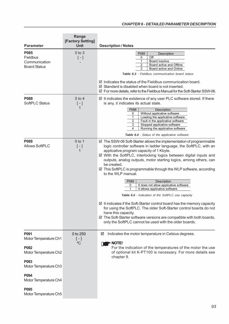
CHAPTER 6 - DETAILED PARAMETER DESCRIPTION
93
Range[Factory Setting]
Parameter Unit Description / Notes
P085 0 to 3Fieldbus [ - ]Communication -Board Status
P085 Description 0 Off 1 Board inactive 2 Board active and Offline 3 Board active and Online
Indicates the status of the Fieldbus communication board. Standard is disabled when board is not inserted. For more details, refer to the Fieldbus Manual for the Soft-Starter SSW-06.
Table 6.3 - Fieldbus communication board status
P088 0 to 4SoftPLC Status [ - ]
1
It indicates the existence of any user PLC software stored. If thereis any, it indicates its actual state.
Table 6.4 - Status of the applicative software
P089 0 to 1Allows SoftPLC [ - ]
1
The SSW-06 Soft-Starter allows the implementation of programmablelogic controller software in ladder language, the SoftPLC, with anapplicative program capacity of 1 Kbyte.
With the SoftPLC, interlocking logics between digital inputs andoutputs, analog outputs, motor starting logics, among others, canbe created.
This SoftPLC is programmable through the WLP software, accordingto the WLP manual.
Table 6.5 - Indication of the SoftPLC use capacity
It indicates if the Soft-Starter control board has the memory capacityfor using the SoftPLC. The older Soft-Starter control boards do nothave this capacity.
The Soft-Starter software versions are compatible with both boards,only the SoftPLC cannot be used with the older boards.
P088 Description 0 Without applicative software 1 Loading the applicative software 2 Fault in the applicative software 3 Stopped applicative software 4 Running the applicative software
P089 Description 0 It does not allow applicative software 1 It allows applicative software
P091 0 to 250Motor Temperature Ch1 [ - ]
ºCP092Motor Temperature Ch2
P093Motor Temperature Ch3
P094Motor Temperature Ch4
P095Motor Temperature Ch5
Indicates the motor temperature in Celsius degrees.
NOTE!For the indication of the temperatures of the motor the useof optional kit K-PT100 is necessary. For more details seechapter 9.
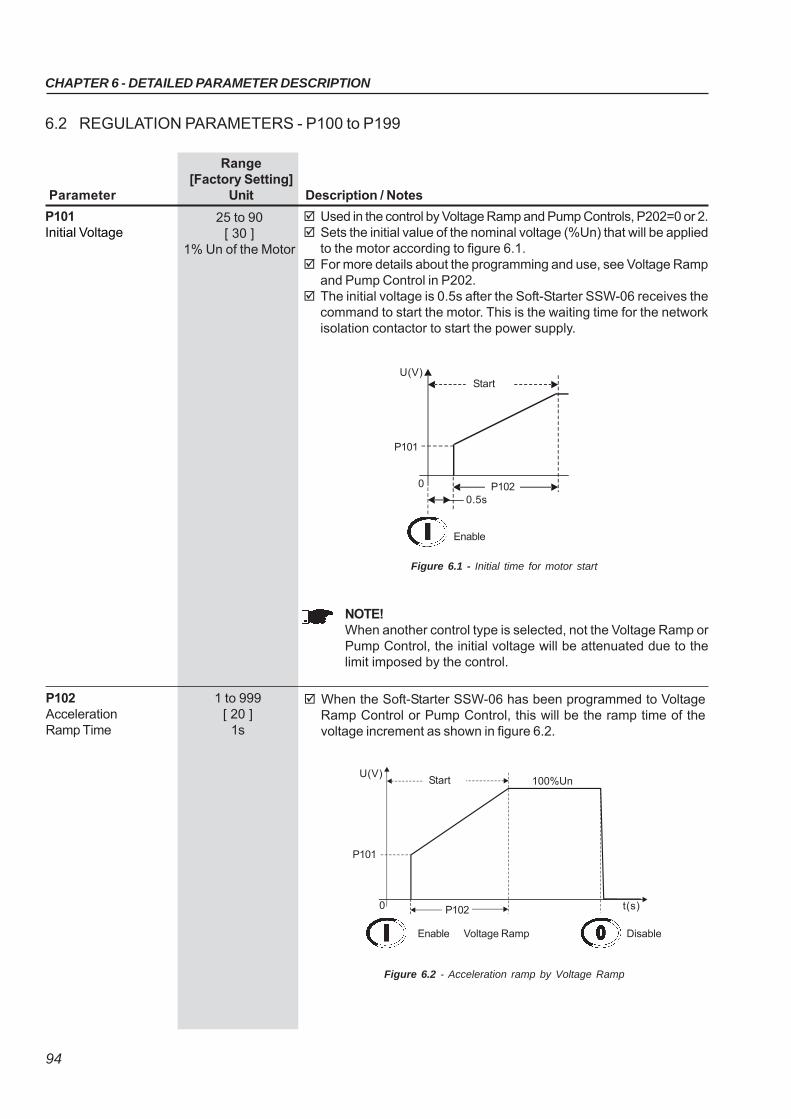
CHAPTER 6 - DETAILED PARAMETER DESCRIPTION
94
Range[Factory Setting]
Parameter Unit Description / Notes
6.2 REGULATION PARAMETERS - P100 to P199
Used in the control by Voltage Ramp and Pump Controls, P202=0 or 2. Sets the initial value of the nominal voltage (%Un) that will be applied
to the motor according to figure 6.1. For more details about the programming and use, see Voltage Ramp
and Pump Control in P202. The initial voltage is 0.5s after the Soft-Starter SSW-06 receives the
command to start the motor. This is the waiting time for the networkisolation contactor to start the power supply.
P101Initial Voltage
25 to 90[ 30 ]
1% Un of the Motor
Start
P1020.5s
0
P101
U(V)
Enable
Figure 6.1 - Initial time for motor start
NOTE!When another control type is selected, not the Voltage Ramp orPump Control, the initial voltage will be attenuated due to thelimit imposed by the control.
P102 1 to 999Acceleration [ 20 ]Ramp Time 1s
When the Soft-Starter SSW-06 has been programmed to VoltageRamp Control or Pump Control, this will be the ramp time of thevoltage increment as shown in figure 6.2.
Figure 6.2 - Acceleration ramp by Voltage Ramp
Start
P1020
P101
U(V)100%Un
t(s)
DisableEnable Voltage Ramp
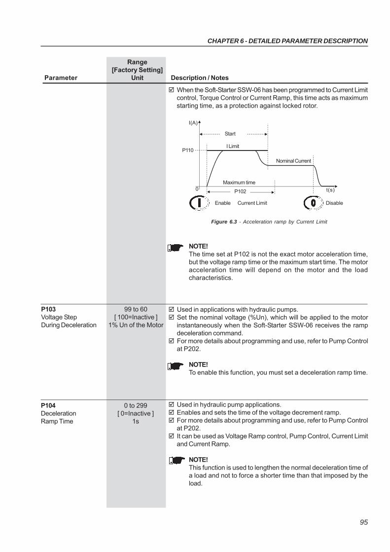
CHAPTER 6 - DETAILED PARAMETER DESCRIPTION
95
Range[Factory Setting]
Parameter Unit Description / Notes
When the Soft-Starter SSW-06 has been programmed to Current Limitcontrol, Torque Control or Current Ramp, this time acts as maximumstarting time, as a protection against locked rotor.
Figure 6.3 - Acceleration ramp by Current Limit
NOTE!The time set at P102 is not the exact motor acceleration time,but the voltage ramp time or the maximum start time. The motoracceleration time will depend on the motor and the loadcharacteristics.
Start
P1020
P110
I(A)
I Limit
t(s)
DisableEnable Current Limit
Nominal Current
Maximum time
P103 99 to 60Voltage Step [ 100=Inactive ]During Deceleration 1% Un of the Motor
Used in applications with hydraulic pumps. Set the nominal voltage (%Un), which will be applied to the motor
instantaneously when the Soft-Starter SSW-06 receives the rampdeceleration command.
For more details about programming and use, refer to Pump Controlat P202.
NOTE!To enable this function, you must set a deceleration ramp time.
P104 0 to 299Deceleration [ 0=Inactive ]Ramp Time 1s
Used in hydraulic pump applications. Enables and sets the time of the voltage decrement ramp. For more details about programming and use, refer to Pump Control
at P202. It can be used as Voltage Ramp control, Pump Control, Current Limit
and Current Ramp.
NOTE!This function is used to lengthen the normal deceleration time ofa load and not to force a shorter time than that imposed by theload.
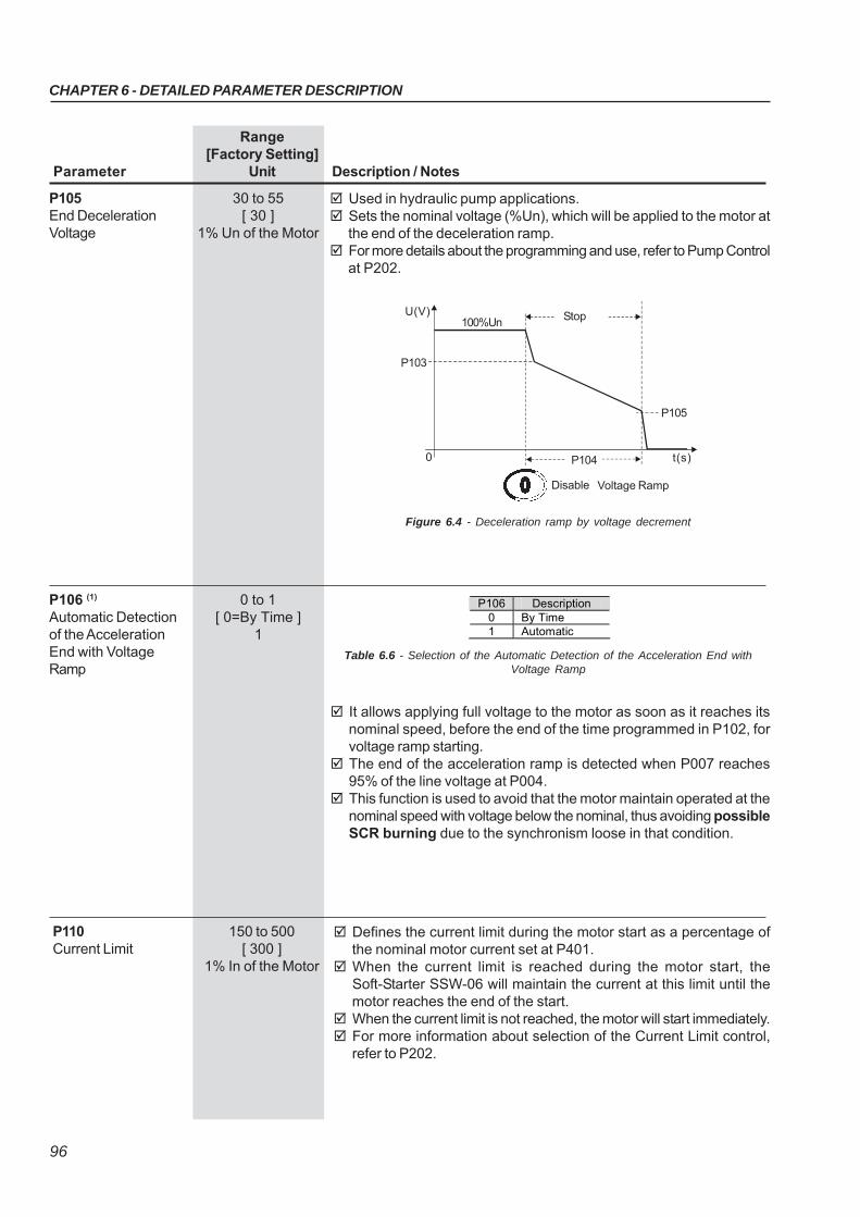
CHAPTER 6 - DETAILED PARAMETER DESCRIPTION
96
Range[Factory Setting]
Parameter Unit Description / Notes
P105 30 to 55End Deceleration [ 30 ]Voltage 1% Un of the Motor
Used in hydraulic pump applications. Sets the nominal voltage (%Un), which will be applied to the motor at
the end of the deceleration ramp. For more details about the programming and use, refer to Pump Control
at P202.
Figure 6.4 - Deceleration ramp by voltage decrement
100%Un
P1040
U(V) Stop
t(s)
Disable Voltage Ramp
P103
P105
P106 (1) 0 to 1Automatic Detection [ 0=By Time ]of the Acceleration 1End with VoltageRamp
It allows applying full voltage to the motor as soon as it reaches itsnominal speed, before the end of the time programmed in P102, forvoltage ramp starting.
The end of the acceleration ramp is detected when P007 reaches95% of the line voltage at P004.
This function is used to avoid that the motor maintain operated at thenominal speed with voltage below the nominal, thus avoiding possibleSCR burning due to the synchronism loose in that condition.
P106 Description 0 By Time 1 Automatic
Table 6.6 - Selection of the Automatic Detection of the Acceleration End with
Voltage Ramp
P110 150 to 500Current Limit [ 300 ]
1% In of the Motor
Defines the current limit during the motor start as a percentage ofthe nominal motor current set at P401.
When the current limit is reached during the motor start, theSoft-Starter SSW-06 will maintain the current at this limit until themotor reaches the end of the start.
When the current limit is not reached, the motor will start immediately. For more information about selection of the Current Limit control,
refer to P202.
CHAPTER 6 - DETAILED PARAMETER DESCRIPTION
97
Range[Factory Setting]
Parameter Unit Description / Notes
Figure 6.5 - Fixed starting Current Limit
P111 150 to 500Initial Current for the [ 150 ]Current Ramp 1% In of the Motor
Used for the control by Current Ramp, P202=4. Allows a current limit ramp to be programmed to help in the starting
of loads that have a lower or higher starting torque. The initial value of the current limit is shown by P111, the final value
is shown by P110 and the time is shown by P112, according to figure6.6.
P112 1 to 99Time for the Current [ 20 ]Ramp 1% of P102
Used for the control by Current Ramp, P202=4. It enables programming the time, in percent of P102, for the end
Current Ramp. After the time, programmed at P112, has elapsed, it starts operation
by Current Limit, given by P110.
Start
P1020
P110
I(A)
t(s)
DisableEnable Current Limit
I Limit
Nominal Current
Maximum Time
a)
Start
P102
0
P110
I(A)
t(s)
DisableEnable Current Ramp
I LimitNominal Current
P111
P112
Maximum Time
Figure 6.6 a) - Current Limit by Current Ramp during Starting
CHAPTER 6 - DETAILED PARAMETER DESCRIPTION
98
Range[Factory Setting]
Parameter Unit Description / Notes
Figure 6.6 b) - Current Limit by Current Ramp during Starting
P120 (1) 1 to 3Starting Torque [ 1=Constant ]Characteristics -
P120 Starting Torque Profile 1 Constant (1 setting point) 2 Linear (2 setting points) 3 Quadratic (3 setting points)
It enables choosing which torque limit profile the Soft-Starter SSW-06will supply to the motor during the start.
Three different types of Torque Limit Profile are available allowing thestart of any type of load: constant or 1 point, linear or 2 points andquadratic or 3 points.
Figure 6.7 a) to c) - Available Torque Profile during the start
Table 6.7 - Starting torque profile
b)
Tn(%)
P121
Start
P120=1
P1020
Tn Nominal
Tn(%)
P121
0t(s) P102 t(s)
P120=2
Tn Nominal
StartP122
Tn(%)
P121
0
P102
t(s)
P120=3
Tn Nominal
StartP122
P123
P124
a) b)
c)
Start
P102
0
P111
I(A)
Nominal Current
t(s)
DisableEnable Current Ramp
P110
P112
I Limit
Maximum Time
CHAPTER 6 - DETAILED PARAMETER DESCRIPTION
99
Range[Factory Setting]
Parameter Unit Description / Notes
NOTE!Choose the type of torque control, easier to program and set,according to the knowledge about the characteristics of the load.
P121 10 to 400Initial Starting [ 30 ]Torque 1% Tn of the Motor
Enables programming an initial torque limit or a constant during thestart, according to the torque type selected at P120.
P120 Action 1 (Constant) P121 limits the maximum torque during the start 2 (Linear) P121 limits the initial torque during the start 3 (Quadratic) P121 limits the initial torque during the start
For more details about programming and application, refer to TorqueControl at P202.
P122 10 to 400End Starting [ 110 ]Torque 1% Tn of the Motor
It enables programming an end torque limit for the start, when alinear or quadratic torque has been selected at P120.
P120 Action 1 (Constant) P122 not used 2 (Linear) P122 limits the end torque during the start 3 (Quadratic) P122 limits the end torque during the start
For more details about programming and application, refer to TorqueControl at P202.
P123 10 to 400Minimum Starting [ 27 ]Torque 1% Tn of the Motor
It enables programming an intermediate torque limit during the start,when a quadratic torque has been selected at P120.
P120 Action 1 (Constant) P123 not used 2 (Linear) P123 not used 3 (Quadratic) P123 limits the intermediate torque during the start
For more details about programming and application, refer to TorqueControl at P202.
P124 1 to 99Time for the Minimum [ 20 ]Start Torque 1% of P102
It enables programming the time for the intermediate torque limitduring the start, as a percentage of the maximum time programmedat P102, when a quadratic torque has been set at P120.
P120 Action 1 (Constant) P124 not used 2 (Linear) P124 not used 3 (Quadratic) P124 time for the intermediate torque limit during the start
For more details about programming and application, refer to TorqueControl at P202.
Table 6.8 - Function of P121 according to P120
Table 6.9 - Function of P122 according to P120
Table 6.10 - Function of P123 according to P120
Table 6.11 - Function of P124 according to P120
CHAPTER 6 - DETAILED PARAMETER DESCRIPTION
100
Range[Factory Setting]
Parameter Unit Description / Notes
P125 (1) 1 to 3Stopping Torque [ 1=Constant]Characteristics -
Here you can choose the torque limit profile that the Soft-StarterSSW-06 shall supply to the motor during the stop.
Three different types of torque profiles are available that permitimproving the speed performance during the stop process.
P125 Stop Torque Profile 1 Constant (1 set point) 2 Linear (2 set points) 3 Quadratic (3 set points)
Figure 6.8 - Available torque profiles for the stop process
NOTE!Choose the type of torque control, easier to program and set,according to the knowledge about the characteristics of the load.
P126 10 to 100End Stop Torque [ 20 ]
1% Tn of the Motor
For more details about programming and application, refer to TorqueControl at P202.
Here you can program the end torque limit or constant for the stop,according to the torque type selected at P125.
Table 6.12 - Stop torque characteristics
Table 6.13 - Function of P126 according to P125
Tn(%)
P126
Stop
P125=1
P104
0
Tn Nominal
t(s)P128
P126
Tn(%)
Tn Nominal
P127
P128
P104
t(s)
P126
P125=2
Stop
0
Tn(%)
P127
100%Tn
P125=3
P104
0
Tn Nominal
t(s)P128
P126
P125 Action 1 (Constant) P126 limits the maximum torque during the stop process 2 (Linear) P126 limits the end torque during the stop process 3 (Quadratic) P126 limits the end torque during the stop process
CHAPTER 6 - DETAILED PARAMETER DESCRIPTION
101
This parameter is reserved for future software versions with hydraulicpump control type. The current version has been developed for thecontrol of centrifugal hydraulic pump, considering quadratic motorloads.
For more details about the Pump Control, see P202.
P130 (1) 0Pump Control [ 0=Pump I ]
-
Range[Factory Setting]
Parameter Unit Description / Notes
For more details about programming and application, refer to TorqueControl at P202.
P125 Action 1 (Constant) P127 not used 2 (Linear) P127 limits the torque when the motor is stopped 3 (Quadratic) P127 limits the intermediate torque for the stop
P128 1 to 99Time for the Minimum [ 50 ]Stop Torque 1% of P104
For more details about programming and application, refer to TorqueControl at P202.
P125 Action 1 (Constant) P128 not used 2 (Linear) P128 not used (time equal to 0) 3 (Quadratic) P128 time for the intermediate torque limit for the stop process
Here you can program the time for the intermediate stop torque, aspercent of the maximum time programmed at P104, when thequadratic torque has been selected at P125.
Table 6.14 - Function of P127 according to P125
Table 6.15 - Function of P128 according to P125
P127 10 to 100Minimum Stop [ 50 ]Torque 1% Tn of the Motor
Here you can program the initial torque limit or an intermediate torquelimit for the stop, when a linear torque or a quadratic torque has beenselected at P125.
Figure 6.9 - Start and Stop by Pump Control
U(V)
P101
0 P102
Start 100%Un
P103
P104
P105
t(s)
Stop
DisableEnable Pump Control
P140 (1) 0 to 1External By-pass [ 0=Inactive ]Contactor -
P140 Action 0 (Inactive) Without external By-pass contactor 1 (Active) With external By-pass contactor
Table 6.16 - External By-pass contactor
This function is enabled when the installation of an external By-passcontactor is required that must be connected in parallel to the Soft-StarterSSW-06.
CHAPTER 6 - DETAILED PARAMETER DESCRIPTION
102
SSW-06 offers two operation modes: Standard Connection or InsideDelta Motor Connection.
When a Standard Connection is used, the motor is connected inseries to the Soft-Starter SSW-06 through three cables.
When an Inside Delta Connection is used, the Soft-Starter SSW-06is connected separately in each winding through six cables (see item3.2.5.2). In this type of connection, the current that flows through theSoft-Starter SSW-06 is only the current of the inside delta motorconnection, in other words, 58% of the nominal motor current. Thischaracteristic changes the relation between the Soft-Starter SSW-06nominal currents and those of the motor. In this connection, the Soft-Starter can be used with its nominal current dimensioned in thefollowing way:
- 1.5 times the nominal motor current during start;- 1.73 times the nominal motor current during full voltage.
During the start, the relation is lower due to the characteristics thatare common to this type of connection (inside delta) the Thyristors ofthe Soft-Starter need to conduct the same current for a lower timeperiod, increasing with this the losses in the Thyristor during thestart.
The standard connection requires less output wiring. The Inside DeltaMotor Connection requires double wiring, but for short distances, thiswill be a cheaper option for the Soft-Starter + motor + wiring set.
ATTENTION!Do not operate the motor when P150 has not been programmedcorrectly. Soft-Starter SSW-06 can be seriously damaged whenthis parameter has not been programmed correctly.
P150 (1)(2) 0 to 1Inside Delta [ 0=Inactive]Motor Connection -
Range[Factory Setting]
Parameter Unit Description / Notes
P150
0 (Inactive)
1 (Active)
Action
Soft-Starter SSW-06 with standard motor connection
Soft-Starter SSW-06 with inside delta motor connection
Table 6.17 - Motor connection type
The models from 85A to 820A have an internal By-pass contactor. The models from 950A to 1400A do not have an internal By-pass
contactor. When P140=1 in the models with an internal By-pass, the internal
By-pass will not enable. The external By-pass contactor is used:
(1) Models without internal By-pass - To allow the connection of anexternal By-pass contactor;
(2) Models with internal By-pass - For instance when a direct start isrequired in case of an emergency. The internal By-pass contactorsdo not permit a direct start. These contactors can be enabled onlyafter the motor start has been realized by the thyristors;
(3) Models with internal By-pass - If the motor stalls frequently duringBy-pass condition.
NOTE!See the recommended setup at items 3.3 and 3.3.12 for moreinformation.
CHAPTER 6 - DETAILED PARAMETER DESCRIPTION
103
Range[Factory Setting]
Parameter Unit Description / Notes
P202 (1) 0 to 4Type of Control [ 0=Voltage
Ramp ]-
P202
0
1
2
3
4
Type of Control
Voltage Ramp
Current Limit
Pump Control
Torque Control
Current Ramp
Table 6.20 - Types of control
Soft-Starter SSW-06 has five starting control types to better matchall application requirements.
Start by Voltage Ramp (1):The start by Voltage Ramp is the most used starting method. TheSoft-Starter SSW-06 applies the voltage to the motor without voltageor current feedback. This method is used for loads with lower initialtorque or quadratic torque.This type of control can be used as initial operating test.
Start by Current Limit (2):The maximum current level is maintained during the start and is setaccording to the application requirements.This method is used for loads with higher initial torque or constant torque.This type of control is used for matching the start process to the limitsof the power supply capacity.
Start by Current Ramp (3):The maximum current level is limited during the start process, howeverhigher or lower current limits can be set during the beginning of the startsequence.
6.3 CONFIGURATION PARAMETERS - P200 to P299
With the Factory Setting, the password will be P000=5. To change the Password, see P000.
P200 0 to 1Password [ 1 ]
-
P200
0 (Inactive)
1 (Active)
Action
This Parameter allows parameter content changing,
independent of P000
Change of Parameter content is only possible, when P000 is
equal to the password value
P201 (2) 0 to 3Language Selection [To be defined
by the user]-
Table 6.18 - Password
P201
0
1
2
3
Description
Português
English
Español
Deutsch
Table 6.19 - Language selection
CHAPTER 6 - DETAILED PARAMETER DESCRIPTION
104
Range[Factory Setting]
Parameter Unit Description / Notes
It can substitute the kick start functions for loads with higher initialtorques.This type of control is used for loads with lower or higher initial torques.This type of control is used to match the start process to the limits ofthe power supply capacity.
Start by Pump Control (4):This type of control provides the required torque for starting and stoppinghydraulic centrifugal pumps smoothly.It has a special algorithm for application in centrifugal pumps, whereloads with quadratic torques are present.This special algorithm aims to minimize pressure “overshoots” in thehydraulic piping, which can result in breakdown or excessive pumpwearing.
Start by Torque Control:The SSW-06 Soft-Starter has a high performance and totally flexibletorque control algorithm to meet the needs of any application, forsmoothly starting or stopping the motor and its load.
Torque Control with 1 setting point (2):This type of control allows a constant starting torque limitation.
Torque Control with 2 setting points (3):This type of control allows the starting torque limitation through linearramp.
Torque Control with 3 setting points (4):This type of control allows the setting of the starting torque limitation atthree different points: initial, intermediate and final. It also allows thestart of quadratic loads, among others.
(1) Very easy to set and program(2) Easy to set and program(3) Set and program, requires knowledge of the load.(4) Set and program, requires extensive knowledge of the load.
NOTES!1) These types of controls are arranged according to the use and
programming difficulty level. Thus, we recommend starting withthe easier control modes first.
2) Every time the content of P202 is changed, the Soft-Starter willstart a sequence routine of minimum settings for each selectedtype of control. You must run and set all parameters of thissequence (up to the last) when required. Only after all settingshave been made can you start the motor.
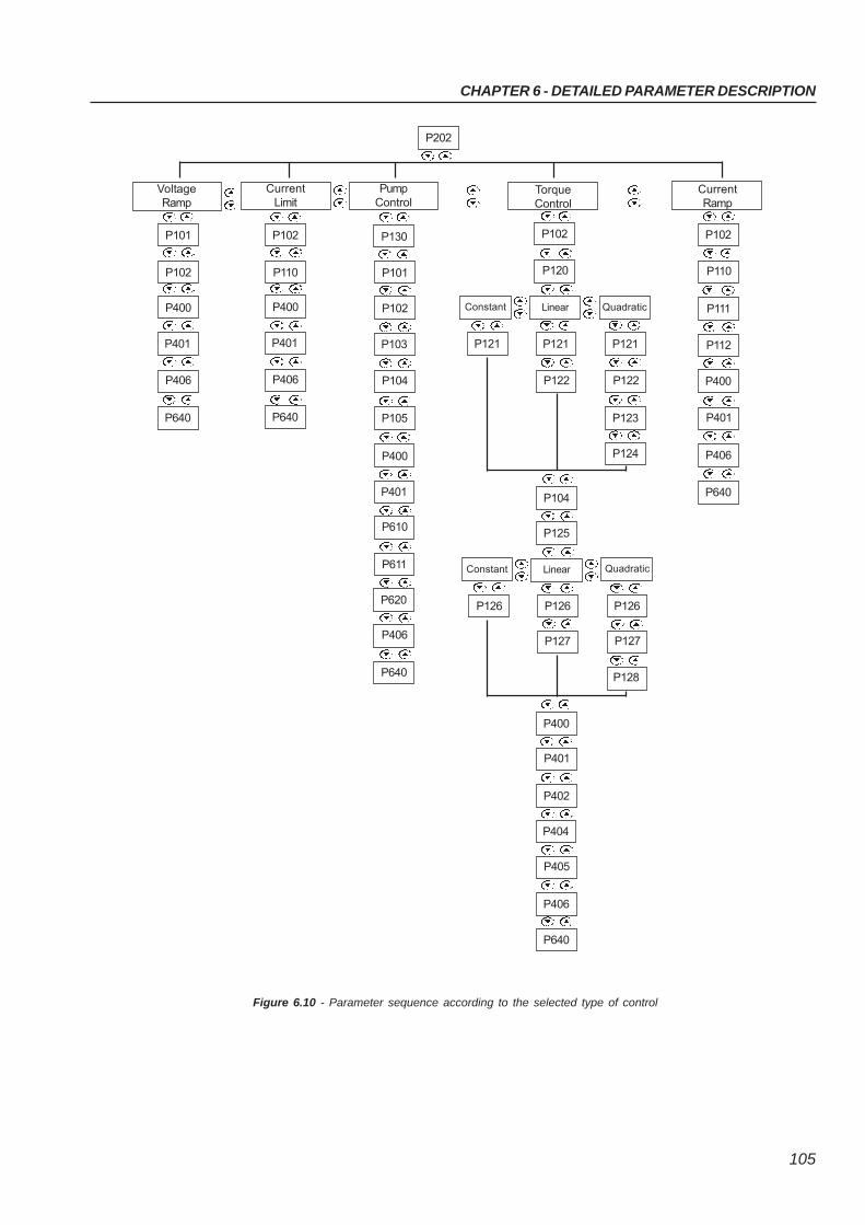
CHAPTER 6 - DETAILED PARAMETER DESCRIPTION
105
Figure 6.10 - Parameter sequence according to the selected type of control
P611
P610
P401
P400
P102
P101
VoltageRamp
CurrentLimit
P202
PumpControl
P640
P406
P401
P400
P110
P102
P105
P104
P103
P102
P101
P130
P640
P406
P401
P400
P640
P406
P620
TorqueControl
CurrentRamp
P120
P102
Constant Linear Quadratic
P123
P122
P121
P122
P121P121
P124
Constant Linear
P128
P127
P126
P127
P126P126
P402
P401
P400
P406
P405
P404
P640
P104
P125
P111
P110
P102
P112
P406
P401
P400
P640
Quadratic
CHAPTER 6 - DETAILED PARAMETER DESCRIPTION
106
Range[Factory Setting]
Parameter Unit Description / Notes
Parameters with note (2) indicated are not changed when FactorySettings are loaded through P204 = 5.
To load User 1 Parameters (P204=7) and/or User 2 (P204=8) in theoperation area of Soft-Starter SSW-06, it is necessary for UserMemory 1 and/or User Memory 2 to have been saved previously(P204=10 and/or P204=11).
P204 (1) 0 to 16Load/Save [ 0 ]Parameters -
Figure 6.11 - Parameter transfer
The table below shows the relation between the adopted starting controltype and the automatically selected stop control type.
Table 6.21 - Stop/Start operation
UserMemory 1
FactorySetting(WEG
Standard)
P204=5Current
Parameter ofSoft-Starter
SSW-06
UserMemory 2
P204=11
P204=
10
P204=
7
P204=8
START
ST
OP
Vol
tage
Ram
p
Cur
rent
Lim
it
Cur
rent
Ram
p
Pum
p C
ontr
ol
Tor
que
Con
trol
Voltage Ramp X Current Limit X Current Ramp X Pump Control X Torque Control X
CHAPTER 6 - DETAILED PARAMETER DESCRIPTION
107
Range[Factory Setting]
Parameter Unit Description / Notes
P204 Action
0, 1, 2, Not used:
6, 9, 12 No action
3 Resets the parameters from P043 to P050
4 Resets the parameters from P053 to P058
5 Loads Factory Default:
Loads current Soft-Starter parameters
with factory settings
7 Loads User 1:
Loads current Soft-Starter parameters
with the values stored in Memory 1.
8 Loads User 2:
Loads current Soft-Starter parameters
with the values stored in Memory 2.
10 Save User 1:
Transfers the current parameter
contents of the Soft-Starter to memory 1
11 Save User 2:
Transfers the current parameter
contents of the Soft-Starter to memory 2
13 Erases the SoftPLC applicative
14 Resets the parameters from P952 to P969
15, 16 Use reserved to the factory
NOTE!Parameter loading/saving will be executed only after parametersetting and after the key has been pressed .
This Parameter selects which parameter listed in table 6.23 will bedisplayed after the Soft-Starter has been powered-up.
P205 0 to 9Display Default [ 2 ]Selection -
Table 6.22 - Action of loading/saving parameters
Table 6.23 - Options display default
P205 Status 0 P001 (Soft-Starter current % In of the Soft-Starter) 1 P002 (Motor current % In of the Motor) 2 P003 (Motor current (A)) 3 P004 (Supply Line Voltage (V)) 4 P005 (Supply Line Frequency (Hz) 5 P006 (Soft-Starter Status) 6 P007 (Output Voltage (V)) 7 P008 (Power Factor) 8 P009 (Motor Torque % Tn of the Motor) 9 P010 (Output Power)
In the event of a fault trip E03, E04, E05, E06, E16, E32, E65, E66,E70, E74, E78, E79, E80 or E81, the Soft-Starter SSW-06 can initiatean automatic reset after the time given by P206 has elapsed.
If P206 ≤ 2 Auto-Reset does not occur.
P206 0 to 600Auto-Reset Time [ 0=Inactive ]
1s
CHAPTER 6 - DETAILED PARAMETER DESCRIPTION
108
Range[Factory Setting]
Parameter Unit Description / Notes
The copy function is used to transfer the content of the parametersfrom one Soft-Starter SSW-06 to another. The Soft-Starters must beof the same type (voltage/current) and the same software version mustbe installed.
P215 (1) 0 to 2Copy Function [ 0=Inactive ]
-
P215 Action Explanation
0 Inactive -
1 Copy Transfers the current parameter contents from the
SSW → HMI Soft-Starter and from Users 1 or 2 to the non-volatile (HMI)
keypad memory (EEPROM). The current Soft-Starter
parameters are not changed.
2 Paste Transfers the contents of the non-volatile (HMI) keypad
HMI → SSW memory (EEPROM) to the current Soft-Starter SSW-06
parameters and to user 1 or 2 memories.
Table 6.24 - Copy function
If after Auto-Reset the same fault is repeated three times consecutively,the Auto-Reset function will be disabled. A fault is consideredconsecutive if it happens again within 30 seconds after Auto-Reset.
Thus if an error occurs four times consecutively, it will be displayedpermanently (and the Soft-Starter will be disabled).
Procedures:1. Connect the keypad to the Soft-Starter SSW-06 from which the
parameters will be copied (Soft-Starter A).2. Set P215=1 (copy) for transferring the parameter from the Soft-Starter A
to the HMI. Press the key . While copy function is being executed,the display will show COPY. P215 resets automatically to 0 (Inactive)after the transfer has been completed.
3. Disconnect the keypad from the Soft-Starter SSW-06.4. Connect the same keypad to the Soft-Starter SSW-06 to which the
parameters should be transferred (Soft-Starter B).5. Set P215=2 (paste) for transferring the content from the non-volatile
keypad memory (EEPROM containing the parameters of theSoft-Starter A) to the Soft-Starter B. Press the key . While thekeypad is executing the paste function, the display shows COPY.When P215 returns to 0, the parameter transfer has been concluded.Now Soft-Starters A and B have the same parameter content.
Please remember:If Soft-Starters A and B command different motors, please check themotor parameters of Soft-Starter B.For copying the parameter contents from Soft-Starter A to otherSoft-Starters, repeat procedures 4 and 5 above.
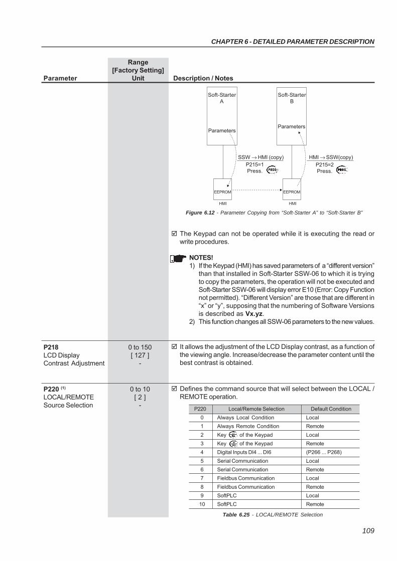
CHAPTER 6 - DETAILED PARAMETER DESCRIPTION
109
Range[Factory Setting]
Parameter Unit Description / Notes
The Keypad can not be operated while it is executing the read orwrite procedures.
NOTES!1) If the Keypad (HMI) has saved parameters of a “different version”
than that installed in Soft-Starter SSW-06 to which it is tryingto copy the parameters, the operation will not be executed andSoft-Starter SSW-06 will display error E10 (Error: Copy Functionnot permitted). “Different Version” are those that are different in“x” or “y”, supposing that the numbering of Software Versionsis described as Vx.yz.
2) This function changes all SSW-06 parameters to the new values.
It allows the adjustment of the LCD Display contrast, as a function ofthe viewing angle. Increase/decrease the parameter content until thebest contrast is obtained.
P218 0 to 150LCD Display [ 127 ]Contrast Adjustment -
Defines the command source that will select between the LOCAL /REMOTE operation.
P220 (1) 0 to 10LOCAL/REMOTE [ 2 ]Source Selection -
Soft-StarterA
Parameters
Soft-StarterB
Parameters
SSW → HMI (copy) HMI → SSW(copy)
Figure 6.12 - Parameter Copying from “Soft-Starter A” to “Soft-Starter B”
EEPROM EEPROM
HMI HMI
P215=1Press.
P215=2Press.
P220 Local/Remote Selection Default Condition
0 Always Local Condition Local
1 Always Remote Condition Remote
2 Key of the Keypad Local
3 Key of the Keypad Remote
4 Digital Inputs DI4 ... DI6 (P266 ... P268)
5 Serial Communication Local
6 Serial Communication Remote
7 Fieldbus Communication Local
8 Fieldbus Communication Remote
9 SoftPLC Local
10 SoftPLC Remote
Table 6.25 - LOCAL/REMOTE Selection
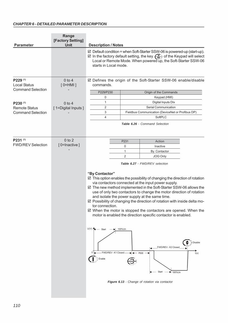
CHAPTER 6 - DETAILED PARAMETER DESCRIPTION
110
Range[Factory Setting]
Parameter Unit Description / Notes
Default condition = when Soft-Starter SSW-06 is powered-up (start-up). In the factory default setting, the key of the Keypad will select
Local or Remote Mode. When powered up, the Soft-Starter SSW-06starts in Local mode.
Defines the origin of the Soft-Starter SSW-06 enable/disablecommands.
P229 (1) 0 to 4Local Status [ 0=HMI ]Command Selection -
P230 (1) 0 to 4Remote Status [ 1=Digital Inputs ]Command Selection -
P229/P230
0
1
2
3
4
Origin of the Commands
Keypad (HMI)
Digital Inputs DIx
Serial Communication
Fieldbus Communication (DeviceNet or Profibus DP)
SoftPLC
Table 6.26 - Command Selection
Table 6.27 - FWD/REV selection
P231
0
1
2
Action
Inactive
By Contactor
JOG Only
“By Contactor” This option enables the possibility of changing the direction of rotation
via contactors connected at the input power supply. The new method implemented in the Soft-Starter SSW-06 allows the
use of only two contactors to change the motor direction of rotationand isolate the power supply at the same time.
Possibility of changing the direction of rotation with inside delta mo-tor connection.
When the motor is stopped the contactors are opened. When themotor is enabled the direction specific contactor is enabled.
P231 (1)
FWD/REV Selection0 to 2
[ 0=Inactive ]-
Figure 6.13 - Change of rotation via contactor
Enable
U(V) 100%Un
t(s)0
100%UnStart
Disable
P630FWD/REV - K1 Closed
FWD/REV - K2 Closed
Start
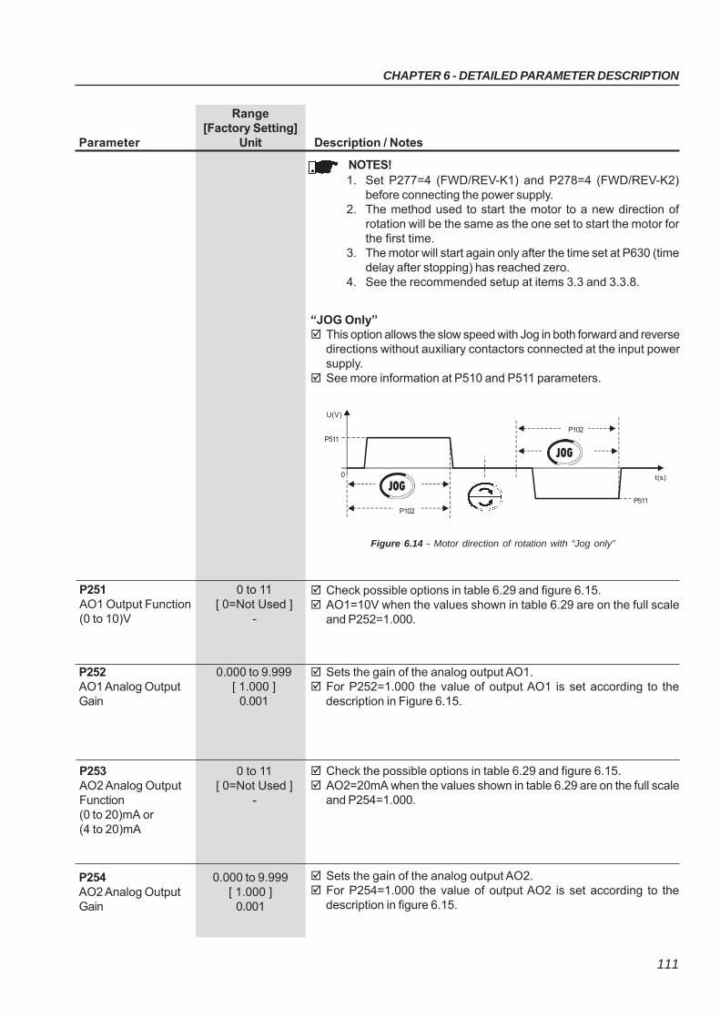
CHAPTER 6 - DETAILED PARAMETER DESCRIPTION
111
Range[Factory Setting]
Parameter Unit Description / Notes
NOTES!1. Set P277=4 (FWD/REV-K1) and P278=4 (FWD/REV-K2)
before connecting the power supply.2. The method used to start the motor to a new direction of
rotation will be the same as the one set to start the motor forthe first time.
3. The motor will start again only after the time set at P630 (timedelay after stopping) has reached zero.
4. See the recommended setup at items 3.3 and 3.3.8.
“JOG Only” This option allows the slow speed with Jog in both forward and reverse
directions without auxiliary contactors connected at the input powersupply.
See more information at P510 and P511 parameters.
Figure 6.14 - Motor direction of rotation with “Jog only”
U(V)
0
P511
P102
P102
P511
t(s)
Check possible options in table 6.29 and figure 6.15. AO1=10V when the values shown in table 6.29 are on the full scale
and P252=1.000.
P251 0 to 11AO1 Output Function [ 0=Not Used ](0 to 10)V -
Sets the gain of the analog output AO1. For P252=1.000 the value of output AO1 is set according to the
description in Figure 6.15.
P252 0.000 to 9.999AO1 Analog Output [ 1.000 ]Gain 0.001
Check the possible options in table 6.29 and figure 6.15. AO2=20mA when the values shown in table 6.29 are on the full scale
and P254=1.000.
P253 0 to 11AO2 Analog Output [ 0=Not Used ]Function -(0 to 20)mA or(4 to 20)mA
Sets the gain of the analog output AO2. For P254=1.000 the value of output AO2 is set according to the
description in figure 6.15.
P254 0.000 to 9.999AO2 Analog Output [ 1.000 ]Gain 0.001
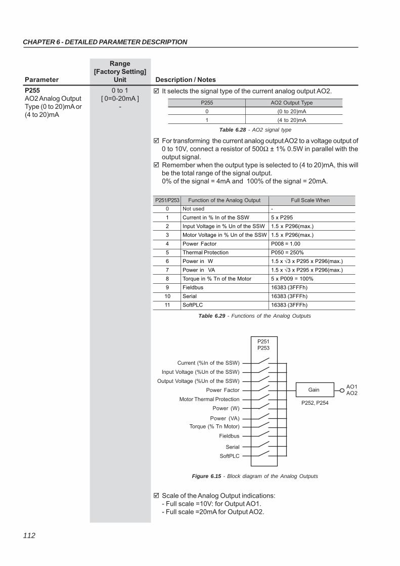
CHAPTER 6 - DETAILED PARAMETER DESCRIPTION
112
Range[Factory Setting]
Parameter Unit Description / Notes
It selects the signal type of the current analog output AO2.P255 0 to 1AO2 Analog Output [ 0=0-20mA ]Type (0 to 20)mA or -(4 to 20)mA
P255 AO2 Output Type
0 (0 to 20)mA
1 (4 to 20)mA
For transforming the current analog output AO2 to a voltage output of0 to 10V, connect a resistor of 500Ω ± 1% 0.5W in parallel with theoutput signal.
Remember when the output type is selected to (4 to 20)mA, this willbe the total range of the signal output.0% of the signal = 4mA and 100% of the signal = 20mA.
Table 6.28 - AO2 signal type
Scale of the Analog Output indications:- Full scale =10V: for Output AO1.- Full scale =20mA for Output AO2.
Current (%In of the SSW)
Input Voltage (%Un of the SSW)
Output Voltage (%Un of the SSW)
Power Factor
Motor Thermal Protection
Power (W)
Power (VA)
Torque (% Tn Motor)
Fieldbus
Serial
SoftPLC
P251P253
Gain
P252, P254
AO1AO2
Figure 6.15 - Block diagram of the Analog Outputs
Table 6.29 - Functions of the Analog Outputs
P251/P253 Function of the Analog Output Full Scale When
0 Not used -
1 Current in % In of the SSW 5 x P295
2 Input Voltage in % Un of the SSW 1.5 x P296(max.)
3 Motor Voltage in % Un of the SSW 1.5 x P296(max.)
4 Power Factor P008 = 1.00
5 Thermal Protection P050 = 250%
6 Power in W 1.5 x √3 x P295 x P296(max.)
7 Power in VA 1.5 x √3 x P295 x P296(max.)
8 Torque in % Tn of the Motor 5 x P009 = 100%
9 Fieldbus 16383 (3FFFh)
10 Serial 16383 (3FFFh)
11 SoftPLC 16383 (3FFFh)
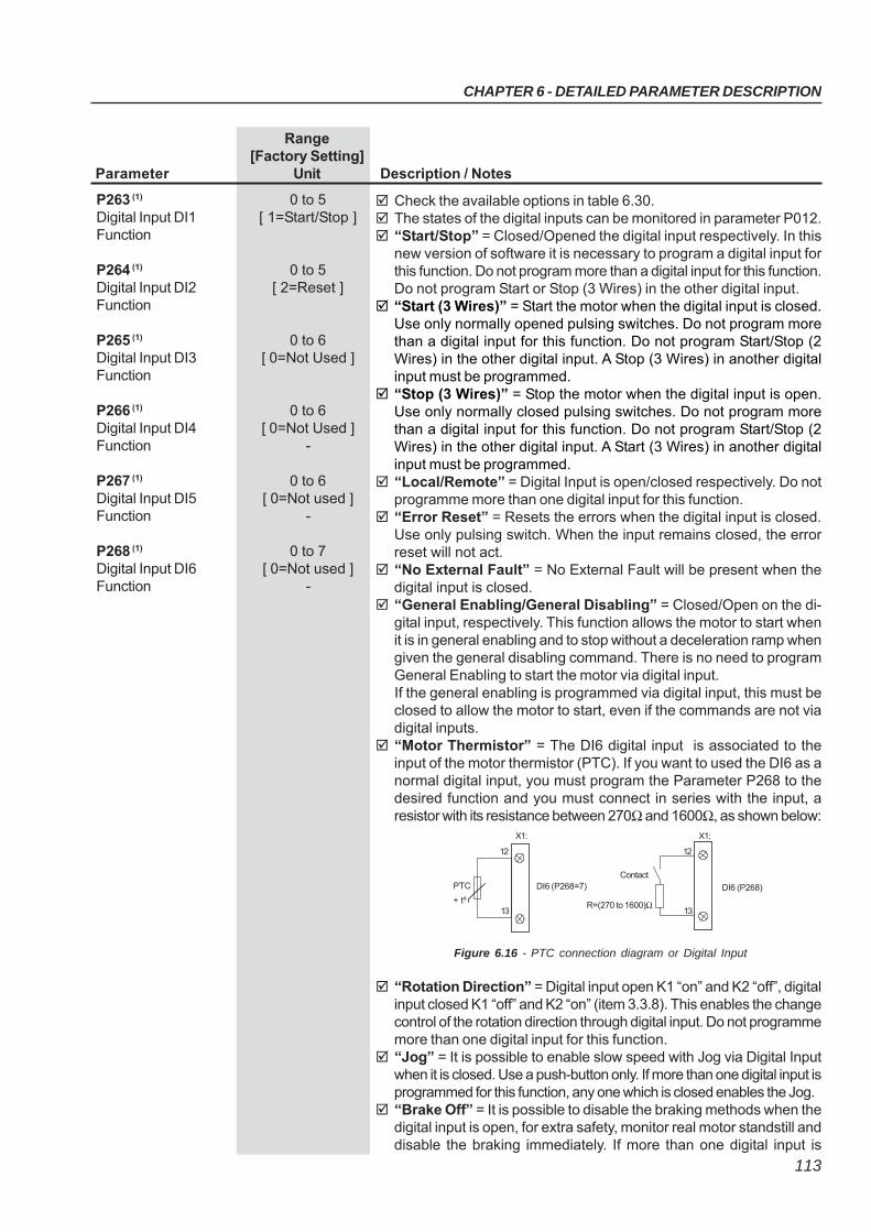
CHAPTER 6 - DETAILED PARAMETER DESCRIPTION
113
Range[Factory Setting]
Parameter Unit Description / Notes
Check the available options in table 6.30. The states of the digital inputs can be monitored in parameter P012. “Start/Stop” = Closed/Opened the digital input respectively. In this
new version of software it is necessary to program a digital input forthis function. Do not program more than a digital input for this function.Do not program Start or Stop (3 Wires) in the other digital input.
“Start (3 Wires)” = Start the motor when the digital input is closed.Use only normally opened pulsing switches. Do not program morethan a digital input for this function. Do not program Start/Stop (2Wires) in the other digital input. A Stop (3 Wires) in another digitalinput must be programmed.
“Stop (3 Wires)” = Stop the motor when the digital input is open.Use only normally closed pulsing switches. Do not program morethan a digital input for this function. Do not program Start/Stop (2Wires) in the other digital input. A Start (3 Wires) in another digitalinput must be programmed.
“Local/Remote” = Digital Input is open/closed respectively. Do notprogramme more than one digital input for this function.
“Error Reset” = Resets the errors when the digital input is closed.Use only pulsing switch. When the input remains closed, the errorreset will not act.
“No External Fault” = No External Fault will be present when thedigital input is closed.
“General Enabling/General Disabling” = Closed/Open on the di-gital input, respectively. This function allows the motor to start whenit is in general enabling and to stop without a deceleration ramp whengiven the general disabling command. There is no need to programGeneral Enabling to start the motor via digital input.If the general enabling is programmed via digital input, this must beclosed to allow the motor to start, even if the commands are not viadigital inputs.
“Motor Thermistor” = The DI6 digital input is associated to theinput of the motor thermistor (PTC). If you want to used the DI6 as anormal digital input, you must program the Parameter P268 to thedesired function and you must connect in series with the input, aresistor with its resistance between 270Ω and 1600Ω, as shown below:
“Rotation Direction” = Digital input open K1 “on” and K2 “off”, digitalinput closed K1 “off” and K2 “on” (item 3.3.8). This enables the changecontrol of the rotation direction through digital input. Do not programmemore than one digital input for this function.
“Jog” = It is possible to enable slow speed with Jog via Digital Inputwhen it is closed. Use a push-button only. If more than one digital input isprogrammed for this function, any one which is closed enables the Jog.
“Brake Off” = It is possible to disable the braking methods when thedigital input is open, for extra safety, monitor real motor standstill anddisable the braking immediately. If more than one digital input is
P263 (1) 0 to 5Digital Input DI1 [ 1=Start/Stop ]Function
P264 (1) 0 to 5Digital Input DI2 [ 2=Reset ]Function
P265 (1) 0 to 6Digital Input DI3 [ 0=Not Used ]Function
P266 (1) 0 to 6Digital Input DI4 [ 0=Not Used ]Function -
P267 (1) 0 to 6Digital Input DI5 [ 0=Not used ]Function -
P268 (1) 0 to 7Digital Input DI6 [ 0=Not used ]Function -
Figure 6.16 - PTC connection diagram or Digital Input
Contact
12
13
X1:
DI6 (P268)
R=(270 to 1600)Ω
DI6 (P268=7)
12
13
X1:
+ tº
PTC
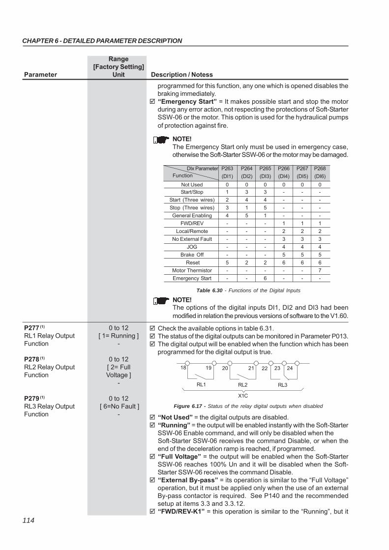
CHAPTER 6 - DETAILED PARAMETER DESCRIPTION
114
Range[Factory Setting]
Parameter Unit Description / Notess
DIx Parameter P263 P264 P265 P266 P267 P268
Function (DI1) (DI2) (DI3) (DI4) (DI5) (DI6)
Not Used 0 0 0 0 0 0Start/Stop 1 3 3 - - -
Start (Three wires) 2 4 4 - - -
Stop (Three wires) 3 1 5 - - -
General Enabling 4 5 1 - - -
FWD/REV - - - 1 1 1
Local/Remote - - - 2 2 2
No External Fault - - - 3 3 3
JOG - - - 4 4 4
Brake Off - - - 5 5 5
Reset 5 2 2 6 6 6
Motor Thermistor - - - - - 7
Emergency Start - - 6 - - -
Table 6.30 - Functions of the Digital Inputs
programmed for this function, any one which is opened disables thebraking immediately.
“Emergency Start” = It makes possible start and stop the motorduring any error action, not respecting the protections of Soft-StarterSSW-06 or the motor. This option is used for the hydraulical pumpsof protection against fire.
P277 (1) 0 to 12RL1 Relay Output [ 1= Running ]Function -
P278 (1) 0 to 12RL2 Relay Output [ 2= FullFunction Voltage ]
-
P279 (1) 0 to 12RL3 Relay Output [ 6=No Fault ]Function -
Check the available options in table 6.31. The status of the digital outputs can be monitored in Parameter P013. The digital output will be enabled when the function which has been
programmed for the digital output is true.
“Not Used” = the digital outputs are disabled. “Running” = the output will be enabled instantly with the Soft-Starter
SSW-06 Enable command, and will only be disabled when theSoft-Starter SSW-06 receives the command Disable, or when theend of the deceleration ramp is reached, if programmed.
“Full Voltage” = the output will be enabled when the Soft-StarterSSW-06 reaches 100% Un and it will be disabled when the Soft-Starter SSW-06 receives the command Disable.
“External By-pass” = its operation is similar to the “Full Voltage”operation, but it must be applied only when the use of an externalBy-pass contactor is required. See P140 and the recommendedsetup at items 3.3 and 3.3.12.
“FWD/REV-K1” = this operation is similar to the “Running”, but it
NOTE!The options of the digital inputs DI1, DI2 and DI3 had beenmodified in relation the previous versions of software to the V1.60.
Figure 6.17 - Status of the relay digital outputs when disabled
18 19 20 21 22 23 24
RL3RL2RL1
X1C
NOTE!The Emergency Start only must be used in emergency case,otherwise the Soft-Starter SSW-06 or the motor may be damaged.
CHAPTER 6 - DETAILED PARAMETER DESCRIPTION
115
Range[Factory Setting]
Parameter Unit Description / Notes
P295 (1)(2) 0 to 20SSW Nominal [ According to theCurrent nominal current
of the Soft-StarterSSW-06 ]
-
Table 6.31 - Functions of the Relay Outputs
RLx Parameter P277 P278 P279
Function (RL1) (RL2) (RL3)
Not Used 0 0 0, 4
Running 1 1 1
Full Voltage 2 2 2
External By-pass 3 3 3
FWD/REV-K1 4 - -FWD/REV-K2 - 4 -
DC-Braking 5 5 5
No Fault 6 6 6
Fault 7 7 7
Fieldbus 8 8 8Serial 9 9 9
SoftPLC 10 10 10
No Alarm 11 11 11Alarm 12 12 12
Breaker Shunt Trip 13 13 13
must be enabled with forward motor direction of rotation. See P231and the recommended setup at items 3.3 and 3.3.8.
“FWD/REV-K2” = this operation is similar to the “Running”, but itmust be enabled with reverse motor direction of rotation. See P231and the recommended setup at items 3.3 and 3.3.8.
“DC-Braking” = the output will be enabled while the DC-Braking isactive. See P500 and the recommended setup at items 3.3 and 3.3.11.
“No Fault” = the output is enabled, if the Soft-Starter SSW-06 is notdisabled due to any error.
“Fault” = the output is enabled, if the Soft-Starter SSW-06 is disableddue to any error.
“Fieldbus”= it makes it possible for the master of a Fieldbuscommunication network to control the digital output. Refer to theFieldbus communication manual for more details.
“Serial”= it makes it possible for the master of a serialcommunication network to control the digital output. Refer to the serialcommunication manual for more details.
“SoftPLC”= it allows the SoftPLC to control the digital output. Referto the WLP Software manual for more details.
“No Alarm”= the output is enabled, if the Soft-Starter SSW-06 isnot disabled due to any alarm.
“Alarm”= the output is enabled, if the Soft-Starter SSW-06 is disableddue to any alarm.
“Breaker Shunt Trip” = Error Group - When one of the followingerrors occur: E11, E15, E18, E19, E41, E77, the output is activated.The tripping of any of these protections may indicate that the SSW-06has a short circuit in the power circuit, thyristors or by-pass. They canbe used to open the power isolation circuit breaker (Q1) (Item 3.3).
Table 6.32 - Nominal current configuration
P295 Nominal Current
P295 Nominal Current
P295 Nominal Current
0 10A 8 170A 16 670A 1 16A 9 205A 17 820A 2 23A 10 255A 18 950A 3 30A 11 312A 19 1100A 4 45A 12 365A 20 1400A 5 60A 13 412A 21 1000A 6 85A 14 480A 22 1300A 7 130A 15 604A
CHAPTER 6 - DETAILED PARAMETER DESCRIPTION
116
Defines the Soft-Starter SSW-06 address on the serial Modbus-RTUcommunication network.
For more information, refer to the Serial Communication Manual forthe Soft-Starter SSW-06.
P308 (1)(2) 1 to 247Soft-Starter Address [ 1 ]on the Serial 1CommunicationNetwork
P309 (1)(2) 0 to 9Fieldbus [ 0=Inactive ]Communication -Board Enabling
Table 6.34 - Fieldbus Communication Protocol Type
Range[Factory Setting]
Parameter Unit Description / Notes
Enables and defines the protocol type of the Fieldbus CommunicationBoard.
For more information, refer to the Fieldbus Communication Manualfor the Soft-Starter SSW-06.
NOTE!Without a Fieldbus Communication Board, this parameter mustremain at 0 (not used).
ATTENTION!Always program this parameter with a voltage that exactlymatches the voltage of the model of your Soft-Starter SSW-06.
P296 (1)(2) 0 to 1Nominal Voltage [ According to the
nominal voltage ofthe Soft-Starter
SSW-06 ]-
P296 Voltage Range 0 220/575V 1 575/690V
Table 6.33 - Voltage range
P310 0 to 1Profibus DP or DP-V1 [ 0=Inactive ]Master Stop Detection 1
P310 Description 0 Inactive 1 Active
Table 6.35 - Selection of the Profibus DP master stop detection
6.4 - SERIAL COMMUNICATION PARAMETERS - P300 to P399
It allows, through the bit 6 of the control word, detecting that themaster of the Profibus DP or DPV1 is stopped. Refer to the Fieldbuscommunication manual for more details.
When it occurs it will indicate E29. In order to prevent the error, themaster must keep the bit 6 in 1.
ATTENTION!Always program this parameter with a current that exactlymatches the current of the model of your Soft-Starter SSW-06,described in the nameplate of the SSW-06. An error inprogramming this parameter may damage your Soft-StarterSSW-06.
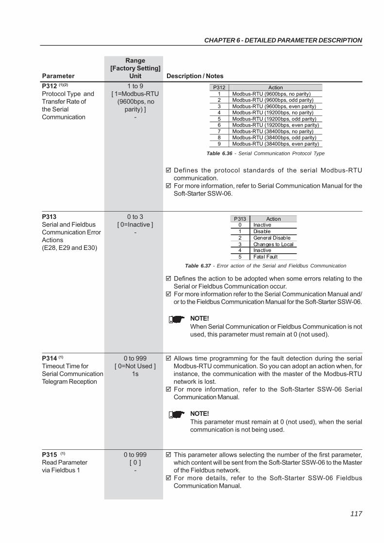
CHAPTER 6 - DETAILED PARAMETER DESCRIPTION
117
Range[Factory Setting]
Parameter Unit Description / Notes
Defines the action to be adopted when some errors relating to theSerial or Fieldbus Communication occur.
For more information refer to the Serial Communication Manual and/or to the Fieldbus Communication Manual for the Soft-Starter SSW-06.
NOTE!When Serial Communication or Fieldbus Communication is notused, this parameter must remain at 0 (not used).
Allows time programming for the fault detection during the serialModbus-RTU communication. So you can adopt an action when, forinstance, the communication with the master of the Modbus-RTUnetwork is lost.
For more information, refer to the Soft-Starter SSW-06 SerialCommunication Manual.
NOTE!This parameter must remain at 0 (not used), when the serialcommunication is not being used.
P314 (1) 0 to 999Timeout Time for [ 0=Not Used ]Serial Communication 1sTelegram Reception
This parameter allows selecting the number of the first parameter,which content will be sent from the Soft-Starter SSW-06 to the Masterof the Fieldbus network.
For more details, refer to the Soft-Starter SSW-06 FieldbusCommunication Manual.
P315 (1) 0 to 999Read Parameter [ 0 ]via Fieldbus 1 -
Defines the protocol standards of the serial Modbus-RTUcommunication.
For more information, refer to Serial Communication Manual for theSoft-Starter SSW-06.
P312 (1)(2) 1 to 9Protocol Type and [ 1=Modbus-RTUTransfer Rate of (9600bps, nothe Serial parity) ]Communication -
P312 Action 1 Modbus-RTU (9600bps, no parity) 2 Modbus-RTU (9600bps, odd parity) 3 Modbus-RTU (9600bps, even parity) 4 Modbus-RTU (19200bps, no parity) 5 Modbus-RTU (19200bps, odd parity) 6 Modbus-RTU (19200bps, even parity) 7 Modbus-RTU (38400bps, no parity) 8 Modbus-RTU (38400bps, odd parity) 9 Modbus-RTU (38400bps, even parity)
Table 6.36 - Serial Communication Protocol Type
P313 0 to 3Serial and Fieldbus [ 0=Inactive ]Communication Error -Actions(E28, E29 and E30)
Table 6.37 - Error action of the Serial and Fieldbus Communication
P313 Action 0 Inactive 1 Disable 2 General Disable 3 Changes to Local 4 Inactive 5 Fatal Fault
CHAPTER 6 - DETAILED PARAMETER DESCRIPTION
118
Range[Factory Setting]
Parameter Unit Description / Notes
Set this parameter value according to the motor nameplate and theconnection diagram in the terminal box.
The motor protection is based on the content of this parameter.
P400 (1) 0 to 999Nominal Motor [ 380 ]Voltage 1V
Set this parameter value according to the motor nameplate. The motor protection against current and the current limit are based
on this parameter content.
NOTES!1) To ensure that these protections operate correctly, the nomi-
nal motor current must not be lower than 30% of the nominalcurrent of the Soft-Starter SSW-06.
2) The use of motors that operate with load duties lower than50% of their rated loads are not recommended.
3) Program the nominal current of the motor according to thepower supply voltage.
P401 (1) 0 to 2424Nominal Motor [ 20 ]Current 0.1A
This parameter allows selecting the number of the third parameter,which content will be sent from the Soft-Starter SSW-06 to the Masterof the Fieldbus network.
For more details, refer to the Soft-Starter SSW-06 FieldbusCommunication Manual.
P317 (1) 0 to 999Read Parameter [ 0 ]via Fieldbus 3 -
This parameter allows selecting the number of the second parameter,which content will be sent from the Soft-Starter SSW-06 to the Masterof the Fieldbus network.
For more details, refer to the Soft-Starter SSW-06 FieldbusCommunication Manual.
P316 (1) 0 to 999Read Parameter [ 0 ]via Fieldbus 2 -
6.5 MOTOR PARAMETERS - P400 to P499
Set the motor speed according to the motor nameplate data. The motor speed must be the same as indicated on the motor
nameplate, already considering its slip.
P402 (1)
Nominal MotorSpeed
400 to 3600[ 1780 ]
1rpm
Set the motor power according to the motor nameplate data. If the power is in CV or HP, multiply the value by 0.74kW.
P404 (1)
Nominal MotorPower
0.1 to 2650[ 75 ]
0.1kW
Set the Motor Power Factor according to the motor nameplate data.P405 (1)
Motor PowerFactor
0 to 1.00[ 0.89 ]
0.01
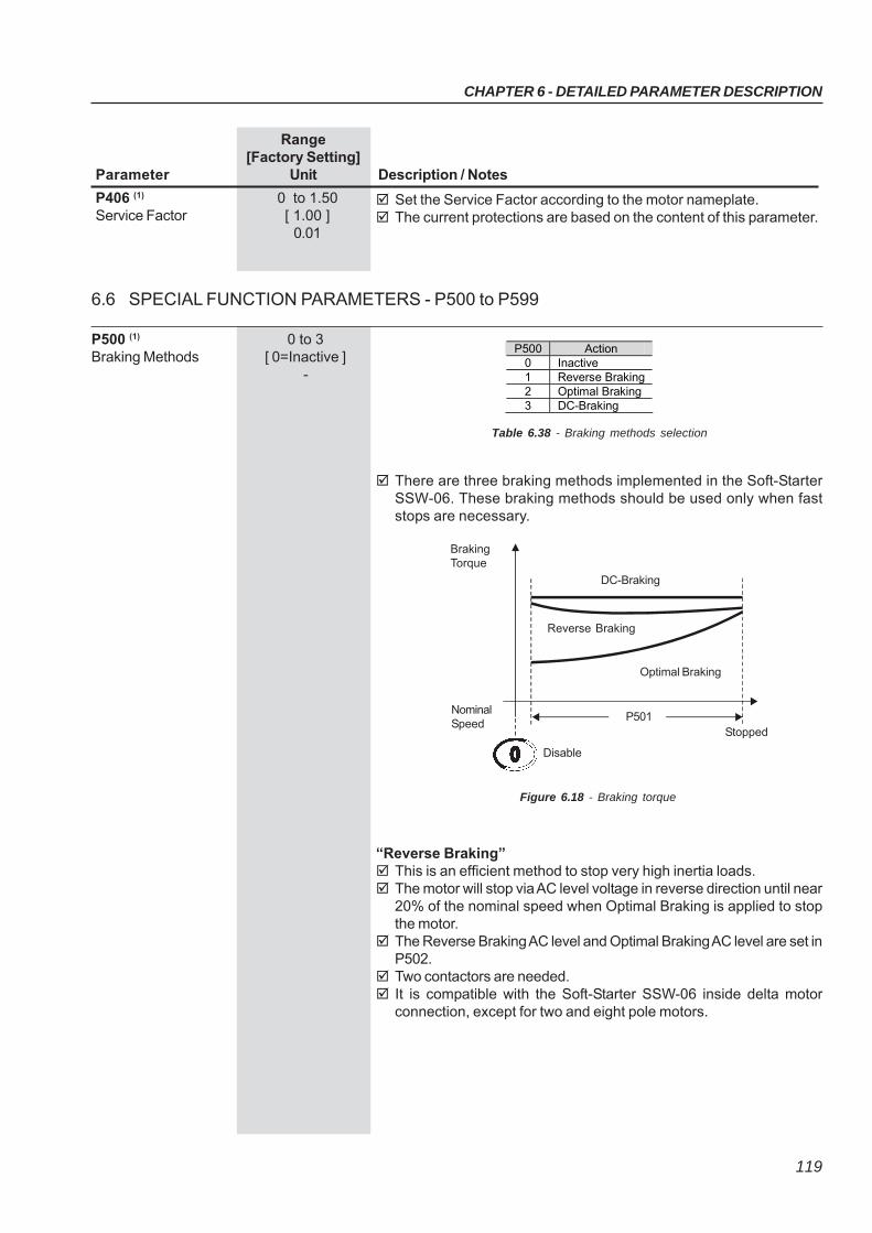
CHAPTER 6 - DETAILED PARAMETER DESCRIPTION
119
Range[Factory Setting]
Parameter Unit Description / Notes
P500 Action 0 Inactive 1 Reverse Braking 2 Optimal Braking 3 DC-Braking
Table 6.38 - Braking methods selection
There are three braking methods implemented in the Soft-StarterSSW-06. These braking methods should be used only when faststops are necessary.
Figure 6.18 - Braking torque
“Reverse Braking” This is an efficient method to stop very high inertia loads. The motor will stop via AC level voltage in reverse direction until near
20% of the nominal speed when Optimal Braking is applied to stopthe motor.
The Reverse Braking AC level and Optimal Braking AC level are set inP502.
Two contactors are needed. It is compatible with the Soft-Starter SSW-06 inside delta motor
connection, except for two and eight pole motors.
P501Stopped
Disable
NominalSpeed
BrakingTorque
DC-Braking
Reverse Braking
Optimal Braking
P500 (1)
Braking Methods0 to 3
[ 0=Inactive ]-
Set the Service Factor according to the motor nameplate. The current protections are based on the content of this parameter.
P406 (1) 0 to 1.50Service Factor [ 1.00 ]
0.01
6.6 SPECIAL FUNCTION PARAMETERS - P500 to P599
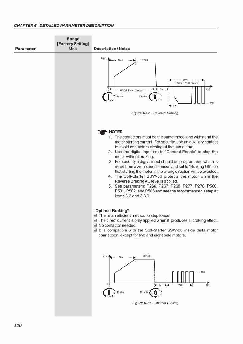
CHAPTER 6 - DETAILED PARAMETER DESCRIPTION
120
Range[Factory Setting]
Parameter Unit Description / Notes
Figure 6.19 - Reverse Braking
StartU(V)
100%Un
Enable Disable
StartP502
t(s)
P501FWD/REV-K2 Closed
FWD/REV-K1 Closed1s0
NOTES!1. The contactors must be the same model and withstand the
motor starting current. For security, use an auxiliary contactto avoid contactors closing at the same time.
2. Use the digital input set to “General Enable” to stop themotor without braking.
3. For security a digital input should be programmed which iswired from a zero speed sensor, and set to “Braking Off”, sothat starting the motor in the wrong direction will be avoided.
4. The Soft-Starter SSW-06 protects the motor while theReverse Braking AC level is applied.
5. See parameters: P266, P267, P268, P277, P278, P500,P501, P502, and P503 and see the recommended setup atitems 3.3 and 3.3.9.
“Optimal Braking” This is an efficient method to stop loads. The direct current is only applied when it produces a braking effect. No contactor needed. It is compatible with the Soft-Starter SSW-06 inside delta motor
connection, except for two and eight pole motors.
Figure 6.20 - Optimal Braking
StartU(V) 100%Un
Enable Disable
P501 t(s)
P502
1s0
CHAPTER 6 - DETAILED PARAMETER DESCRIPTION
121
Range[Factory Setting]
Parameter Unit Description / Notes
NOTES!1. Use a digital input set to "General Enable" to stop the motor
without braking.2. Use one digital input set to "Braking Off", for extra safety,
for monitoring the real motor standstill and disables thebraking immediately.
3. For high inertia loads it is recommended to use a PTC motorinput.
4. It is not recommended to use Optimal Braking with two andeight pole motors.
5. See parameters: P266, P267, P268, P500, P501, P502,P503 and see the recommended set-up at items 3.3 and3.3.10.
“DC-Braking” This is an old and efficient method to stop very high inertia loads. The direct current is applied all the time until the motor stops. One contactor is needed to short-circuit the output lines U and V.
The method differs from SSW-03 and SSW-04. The necessary current to stop the motor is very high and continuously
applied. It is not compatible with the Soft-Starter SSW-06 inside delta motor
connection.
Figure 6.21 - DC-Braking
NOTES!1. Use a digital input set to "General Enable" to stop the motor
without braking.2. Use one digital input set to "Braking Off", for extra safety,
for monitoring the real motor standstill and disabling thebraking immediately.
3. It is recommended to use a PTC motor input.4. See parameters: P266, P267, P268, P277, P278, P279,
P500, P501, P502, P503 and see the recommended set-upat items 3.3 and 3.3.11.
StartU(V)
100%Un
Enable Disable
P502
t(s)P501DC-Brake RLXClosed
1s0 Rotation direction K1 closed
CHAPTER 6 - DETAILED PARAMETER DESCRIPTION
122
Range[Factory Setting]
Parameter Unit Description / Notes
P501 sets the maximum time that the braking voltage is applied.
ATTENTION!1. This is the main protection of all braking methods. Set it
according to the application, so that the Soft-Starter SSW-06and the motor can withstand the settings.
2. The parameters: P001, P002, P003, P008, P009, P010 andP011 are set to zero during Optimal Braking and DC-Braking.
3. The current protections do not work with a DC currentbecause the current transformers saturate with DC current.
4. The Soft-Starter SSW-06 does not protect the motor while itis performing braking, if no motor PTC sensor is used.
P501Braking Time
1 to 299[ 10 ]
1s
P502 sets the braking voltage level. It is based on the AC line voltageconverted to DC voltage.
This parameter also sets the level of the AC Reverse Braking.
ATTENTION!1. Be careful with this voltage level. Set it according to the
application so that the Soft-Starter SSW-06 and the motorcan withstand the settings.
2. Start with low voltage levels and increase them according tothe need.
3. The current protections do not work with a DC currentbecause the current transformers saturate with DC current.
4. The Soft-Starter SSW-06 does not protect the motor while itis performing the braking, if no motor PTC sensor is used.
5. To measure this current during braking you need a specialcurrent meter with hall effect transformers.
P502Braking Voltage Level
30 to 70[ 30 ]
%
P503Braking End Detection
0 to 1[ 0=Inactive ]
-
P503 Description 0 Inactive 1 Automatic
Table 6.39 - Braking end detection
This parameter sets the automatic detection of the motor standstill.
NOTES!1. This function does not work with two and eight pole motors.2. This function does not work with inside delta motor
connections.3. The motor standstill detection can vary with the motor
temperature.4. Always use the braking time (P501) as the main protection.
CHAPTER 6 - DETAILED PARAMETER DESCRIPTION
123
Range[Factory Setting]
Parameter Unit Description / Notes
This parameter enables the fixed slow speed with Jog. Slow speed with Jog forward direction is about 1/7 of the nominal
speed. Slow speed with Jog reverse direction is about 1/11 of the nominal
speed.
P510 (1)
Jog0 to 1
[ 0=Inactive ]-
P510 Action 0 Inactive 1 Active
Table 6.40 - Jog selection
Table 6.41 - Jog and motor direction of rotation
This parameter sets the slow speed torque level with Jog.
ATTENTION!1. Be careful with this torque level. Set it according to the
application so that the Soft-Starter SSW-06 and the motorcan withstand the settings.
2. The motor can be enabled during a short period of timeonly, with Jog. Connect a push-button to a digital input toenable the Jog.
3. The P102 parameter is the time limit protection of the Jog.If this time is exceeded, fault E62 will appear.
4. The parameters: P001, P002, P003, P008, P009, P010 andP011 are set to zero during the Jog Function.
5. The current protections do not work with the Jog currentbecause the current transformers saturate with the low Jogfrequency.
6. The Soft-Starter SSW-06 does not protect the motor duringa Jog without the use of a PTC sensor on the motor.
7. To correctly measure the currents during the Jog, it isnecessary to use hall effect transformers.
P511Jog Level
10 to 100[ 30 ]1%
P510 P231 Action 0 Inactive) - without Jog 1 (Active) 0 (Inactive) allows the slow speed with Jog only in forward
direction. 1 (Active) 1 (By Contactor) allows the slow speed with Jog in the same
direction of the power supply and the auxiliary contactors connected at the input power supply, changing the motor direction of rotation.
1 (Active) 2 (JOG Only) allows the slow speed with Jog in both forward and reverse directions without contactors.
CHAPTER 6 - DETAILED PARAMETER DESCRIPTION
124
Range[Factory Setting]
Parameter Unit Description / Notes
The Soft-Starter SSW-06 allows for the use of a torque pulse duringthe starting process for loads that have high resistance during thestarting process.
Enabled through P520=1. The duration of this pulse may be adjustedat P521.
This pulse will be applied according to the type of control selected atP202:- Voltage ramp: the voltage level may be set at P522.- Current limit: the current level may be set at P523.- Current ramp: with adjustable current level at P523.
NOTES!1) Use this function only for specific applications, when required.2) This function is not required for Torque Control.
P520 (1) 0 to 1Kick Start [ 0=Inactive ]Torque Pulse -
P521 0.1 to 2Kick Start [ 0.1 ]Pulse Time 0.1s
P522 70 to 90Kick Start [ 70 ]Voltage Pulse Level 1 %Un of the motor
P523 300 to 700Kick Start [ 500 ]Current Pulse Level 1 %In of the motor
Figure 6.22 - Actuation levels of the starting torque pulse
StartI(A)
I Limit
t(s)P102
DisableEnable Current Ramp
0
P110
P523
P521
Nominal Current
Maximum Time
P112
P111
StartI(A)
I Limit
t(s)P102
DisableEnable Current Limit
0
P110
P523
P521
I Nominal
StartU(V)
100%Un
t(s)P102
DisableEnable Voltage Ramp
0
P101
P522
P521
CHAPTER 6 - DETAILED PARAMETER DESCRIPTION
125
Range[Factory Setting]
Parameter Unit Description / Notes The under and overvoltage are settings as percentage of the motor
nominal voltage (P400). P600 sets the immediate undervoltage level at which the motor can
operate without problems during the time adjusted in P601. Afterthis time has elapsed the Soft-Starter is disabled indicatingundervoltage fault.
P602 sets the maximum overvoltage level that the motor allows, forthe time that has been set at P603. If this time is exceeded, theSoft-Starter is disabled and an Overvoltage Error is displayed.
For programming examples refer to the item 7.2.2.
NOTE!These functions are active for the entire time that the motor isrunning.
P600 (1) 0 to 30Immediate [ 20 ]Undervoltage 1 %Un of the Motor
P601 (1) 0 to 99Immediate [ 1 ]Undervoltage Time 1s
P602 (1) 0 to 30Immediate [ 15 ]Overvoltage 1 %Un of the Motor
P603 (1) 0 to 99Immediate [ 1 ]Overvoltage Time 1s
6.7 PROTECTION PARAMETERS - P600 to P699
U(V)
Nominal
t(s)
DisableEnable
0
P600
P602
Decelerationramp
RunningActuation Region
U(V)
P602
P600
t0 P601 t1(s) t0 P603 t1(s)
Undervoltage
Nominal
FaultAction
Nominal
Overvoltage
FaultAction
Figure 6.23 - Actuation levels in case of undervoltage and overvoltage
U (V)
Voltage Imbalance between phases is set as a percentage of thenominal motor voltage (P400).
P604 sets the maximum voltage difference between the three linephases at which the motor can operate without problems, for the timeset at P605. If these values are exceeded, the Soft-Starter is switchedOff and the Voltage Imbalance error is displayed.
These settings also activate the phase fault protection during thestarting process and during operation at full voltage.
NOTE!This function is always active when the motor is running.
P604 (1) 0 to 30Voltage Imbalance [ 15 ]between Phases 1%Un of the Motor
P605 (1) 0 to 99Voltage Imbalance [ 1 ]between Phases 1sTime
CHAPTER 6 - DETAILED PARAMETER DESCRIPTION
126
Range[Factory Setting]
Parameter Unit Description / Notes
The undercurrent and the overcurrent parameters are set as percentageof the nominal motor current (P401).
P610 sets the immediate undercurrent level at which the motor canoperate without problems during the time adjusted in P611. After thistime has elapsed the Soft-Starter is disabled indicating undercurrentfault. This function is generally used in applications with hydraulicpumps which cannot be operated without a load.
P612 sets the maximum overcurrent levels that the motor or Soft-Starter allows for the time set at P613, after which the Soft-Starter isswitched Off and the Overcurrent Error is displayed.
For programming examples refer to the item 7.2.2.
NOTE!These Functions are only active after the motor start and after fullvoltage level has been reached.
P610 (1) 0 to 99Immediate [ 20 ]Undercurrent 1%In of the Motor
P611 (1) 0 to 99Immediate [ 0=Inactive ]Undercurrent Time 1s
P612 (1) 0 to 99Immediate [ 20 ]Overcurrent 1%In of the Motor
P613 (1) 0 to 99Immediate [ 0=Inactive ]Overcurrent 1sTime
Figure 6.24 - Actuation Levels for Overcurrent and Undercurrent
I(A)
0
P610
P612Start
Nominal
DisableEnable
Actuation Region
t(s)
I(A)
t
P610
P612
t(s)
Nominal
Fault Action
Fault ActionI(A)
Nominal
t(s)tP611 P613
Undercurrent
Overcurrent
The current imbalance values are set as percentage of the nominalmotor current (P401).
P614 sets the maximum current difference between the three motorphases at which the motor can operate without problems, for the timeset at P615. If these values are exceeded, the Soft-Starter is switchedOff and the Current Imbalance error is displayed.
These settings also activate the phase fault protection during thestarting process and during operation at full voltage.
NOTE!This function is actuated only after motor start and after full voltagelevel has been reached.
P614 (1) 0 to 30Current Imbalance [ 15 ]between Phases 1 %In of the Motor
P615 (1) 0 to 99Current Imbalance [ 1 ]between 1sPhases Time
CHAPTER 6 - DETAILED PARAMETER DESCRIPTION
127
Range[Factory Setting]
Parameter Unit Description / Notes
This function, when enabled, ensures protection against undercurrentbefore By-pass closing and preventing By-pass closing in case ofany supply line fault of any thyristor.
When this function is disabled, the motor can be started with nominalcurrent lower than 10% of the nominal Soft-Starter current.
NOTE!This function should be disabled only when motors with lowcurrents are tested.
P616 (1) 0 to 1Undercurrent Before [ 1=Active ]By-pass Closing -
When this function is enabled it ensures protection against lockedrotor at the end of the start and it prevents the By-pass closing whenan overcurrent two times the nominal motor current is detected.
NOTE!Disable this function only when the motor can withstand loadswith higher currents.
P617 (1)
Locked Rotor at theStart End
0 to 1[ 1=Active ]
-
The function of this parameter is to protect loads that can be run onlyin one direction of rotation. When this function is enabled, only thephase sequence R/1L1, S/3L2, T/5L3 is permitted.
When this function is enabled, the phase sequence is detected everytime the motor is powered-up.
The function is very useful for driving hydraulic pumps which can beoperated only in one direction of rotation.
P620 (1) 0 to 1RST Phase Sequence [ 0=Inactive ]
-
Its function is to protect the motor when a short circuit occurs in thepower circuit of the SSW-06 Soft-Starter, thyristors or by-pass with themotor stopped, that is, without the Run command.
NOTE!This protection will only be actuated through contactor (K1) or circuit breaker (Q1) of the power isolation (Item 3.3), and it is
P622 (1) 0 to 1Short circuit in the [ 0 = Inactive ]SSW power
The ground fault values are adjusted in percentage of the Soft-Starternominal current.
P618 adjusts the maximum instantaneous value of current imbalanceat which the motor can operate without problems during the timeadjusted in P619. After this time has elapsed the Soft-Starter is disabledindicating ground fault E11.
This protection works only during full voltage operation.
NOTE!This protection does not replace earth fault relays that arenormally used for human life protection and have low trip levels.
P618 (1) 10 to 30Ground Fault [ 20 ]
1% In of the SSW
P619 (1) 0 to 10.0Ground Fault Time [ 0=Inactive ]
0.1s
Its function is to indicate imperfection in the opening of the by-passcontactor when the motor has been switch off, indicating By-passContactor Closed fault E77. The fault is indicated with by-pass internalor external.
NOTE!Disable this protection only to make possible the use of theSSW-06 in multimotor applications, that is, when a SSW-06starts more than a motor.
P621 (1)
By-pass ContactorClosed
0 to 1[ 1=Active ]
CHAPTER 6 - DETAILED PARAMETER DESCRIPTION
128
Range[Factory Setting]
Parameter Unit Description / Notes
Figure 6.25 - Operation via keypad and .
Figure 6.26 - Operation via three-wire digital inputs (DI1 and DI2)
Un P104=0
P630=10s
Un P104=6s
t
t
P630=10s
Un P104=0
P630=10s t
t
Un P104=6s
P630=10sP630=10s
This function limits the minimum time interval to a new start after themotor has been switched Off.
NOTE!The behavior of this function has changed, if compared to thesoftware versions that preceded the V1.40. Now the time intervalstarts after power is removed from the motor.
P630 2 to 999Interval of Time [ 2 ]After Stop 2s
deactivated by the error output.
CHAPTER 6 - DETAILED PARAMETER DESCRIPTION
129
Range[Factory Setting]
Parameter Unit Description / Notes
NOTE!The start command will be executed only after the time intervalprogrammed at P630 has elapsed.
NOTES!1) The time interval starts to be counted at the moment when the
motor switch Off command is given, if a deceleration ramp hasbeen programmed or not.
2) This function is only active when the time interval, which hasbeen set at P630, is longer than the time set at P104 for thedeceleration process, if programmed.
3) If the control board supply is removed, or if the microcontrolleris reset, no time counting occurs.
The Soft-Starter SSW-06 has a rigid thermal protection that is efficientand totally programmable for the protection of your motor. All Soft-Starter SSW-06 models are fitted with this protection device. Whenactivated, error E05 (overload) will be displayed and the motor will beswitched off.
This thermal protection has curves that simulate the motor heatingand cooling. The calculation is executed by complex Software, thatestimates the motor temperature through True RMS current suppliedto the motor.
The actuation curves of the Thermal Protection are based onIEC 60947-4-2 standard.
P640 (1) 0 to 9Motor Protection [ 6=30 ]Thermal Class 1
P640 Action 0 Inactive 1 Class 5 2 Class 10 3 Class 15 4 Class 20 5 Class 25 6 Class 30 7 Class 35 8 Class 40 9 Class 45
Table 6.42 - Thermal classes
Figure 6.27 - Operation via digital input (DI1)
UnP104=0
P630=10s t
t
UnP104=6s
P630=10s
CHAPTER 6 - DETAILED PARAMETER DESCRIPTION
130
Range[Factory Setting]
Parameter Unit Description / Notes
Figure 6.28 - Thermal protection classes for cold motor
Class 45Class 40Class 35Class 30Class 25Class 20Class 15
Class 10
Class 5Currentx In
S.F.=1
S.F.=1.15
9x
9x
8x
8x 10x
7x
7x
6x
6x
5x
5x
4x
4x
3x
3x
2x
2x
1x
1x
1
10
100
1000
Timet(s)
Class
3xIn
5xIn
7xIn
40
135s
48.1s
24.5s
30
101.2s
36.1s
18.3s
Table 6.43 - Thermal protection class times for cold motor with S.F.=1
10
33.7s
12s
6.1s
20
67.5s
24s
12.2s
Table 6.44 - Thermal protection class times for cold motor with S.F.=1.15
Class
3xIn
5xIn
7xIn
40
180.2s
63.6s
32.4s
30
135.1s
47.7s
24.3s
10
45.1s
15.9s
8.1s
20
90.1s
31.8s
16.2s
The heating and cooling curves are based on WEG's extensiveexperience with motor development. These curves adopt WEG three-phase IP55 standard motors. They also consider if the motor is forcecooled or not when driven.
The cooling time of the thermal image depends on the motor power, whichmeans that each different power rating will have different cooling times.When reduction of this cooling time is required, you can use P641.
The estimated motor temperature is saved in non-volatile memory everytime the power supply of the control board is switched off. Thus, whenthe control board is switched on again, the last value saved will return.
CHAPTER 6 - DETAILED PARAMETER DESCRIPTION
131
Range[Factory Setting]
Parameter Unit Description / Notes
Table 6.45 - Thermal protection class times for hot motor
Class
3xIn
5xIn
7xIn
40
47.2s
16.8s
8.5s
30
35.4s
12.6s
6.4s
10
11.8s
4.2s
2.1s
20
23.6s
8.4s
4.2s
Current in % of In of the Motor Factor 0%(cold) 1
20% 0.87 40% 0.74 60% 0.61 80% 0.48
100% (rated load) 0.35
Table 6.46 - Multiplication factor of the cold thermal classes time to obtain hotthermal class times
Figure 6.29 - Thermal protection classes for hot motor with 100% In
Class 45Class 40Class 35Class 30Class 25Class 20Class 15
Class 10
Class 5
Currentx In
9x8x7x6x5x4x3x2x1x
1
10
100
1000
Timet(s)
0,1
CHAPTER 6 - DETAILED PARAMETER DESCRIPTION
132
Range[Factory Setting]
Parameter Unit Description / Notes
NOTE!As there are several Thermal Protection Classes, you mustprogram that Thermal Protection Class that best meets yourapplication and protects the motor during its allowed duty.
NOTE!The SSW-06 Soft-Starter thermal class times are an evolution ofthe previous WEG Soft-Starters, therefore the times are differentto those of the SSW-03 and SSW-04. The class to be adoptedmust be in accordance with the SSW-06 graphs.
NOTE!When using a motor with a PTC thermal sensor or thermostatconnected to the SSW-06 Soft-Starter, there is no need to enablethe Thermal Classes, therefore set P640=0.
Sets the time for the auto-reset of the thermal image of the motor. This function can be used for applications that require several starts
per hour or those with short intervals of time between starting andstopping the motor.
The motor cooling curves are based on many years of experience ofWEG developing motors. They adopt the Standard IP55 Three PhaseMotors with temperature elevation of 60K as a standard. They alsoconsider if the motor is cool when switched on or not.
The thermal image cool time depends on the power of the motor, inother words, for each power rating there is a different cooling time.
The thermal image can also be reset if parameter P640=0 isprogrammed, returning to the desired Thermal Class afterwards.
P641 (1) 0 to 600Auto-Reset of the [ 0=Inactive ]Thermal Memory 1s
Motor
On
Off
ActuationLevel
Motor
On
Off
ActuationLevel
Auto-resettime
with reset
E05
t
t
twhithoutreset
E05
t
Figure 6.30 - Auto-reset of the thermal memory
NOTE!Please consider, that when using this function, the useful lifetime of the motor winding can be reduced.
CHAPTER 6 - DETAILED PARAMETER DESCRIPTION
133
Range[Factory Setting]
Parameter Unit Description / Notes
This function allows setting levels for a motor thermal protection alarm. P642 sets the alarm level for the motor thermal protection. P643 sets the reset level for the motor thermal protection alarm. In order that this function works, P705 (Motor Thermal Protection
Trip) must be set to 1 (Alarm) or 2 (Fault and Alarm).
NOTE!The alarm level adjusted in P642 must be higher than the resetlevel adjusted in P643.
P642Motor ThermalProtection Alarm
P643Motor ThermalProtection AlarmReset
0 to 250[ 230 ]
1%
0 to 250[ 210 ]
1%
Figure 6.31 - Motor thermal protection alarm programming
SET RESET
E05
t0
P643
P642
P050
The Overtorque and Undertorque values are adjusted in percentage ofthe motor nominal torque (100%).
P650 sets the immediate Undertorque level at which the motor canoperate during the time adjusted in P651. After this time has elapsedthe Soft-Starter is disabled indicating Undertorque fault. This functioncan be used in applications with hydraulic pumps that cannot operatewithout load.
P652 sets the immediate Overtorque level at which the motor canoperate during the time adjusted in P653. After this time has elapsedthe Soft-Starter is disabled indicating Overtorque fault.
For programming examples see the item 7.2.2.
NOTE!These functions work only with full voltage, after the motor hasbeen started.
P650 (1)
ImmediateUndertorque
P651 (1)
ImmediateUndertorque Time
P652 (1)
Immediate Overtorque
P653 (1)
Immediate OvertorqueTime
0 to 99[ 30 ]
1% Tn of the Motor
0 to 99[ 0=Inactive ]
1s
0 to 99[ 30 ]
1% Tn of the Motor
0 to 99[ 0=Inactive ]
1s
CHAPTER 6 - DETAILED PARAMETER DESCRIPTION
134
Range[Factory Setting]
Parameter Unit Description / Notes
The Overpower and Underpower values are adjusted in percentage ofthe nominal motor power (P404).
P660 sets the immediate Underpower level at which the motor canoperate during the time adjusted in P661. After this time has elapsedthe Soft-Starter is disabled indicating Underpower fault. This functioncan be used in applications with hydraulic pumps that cannot operatewithout load.
P662 sets the immediate Overpower level at which the motor canoperate during the time adjusted in P663. After this time has elapsedthe Soft-Starter is disabled indicating Overpower fault.
For programming examples see the item 7.2.2.
NOTE!These functions work only with full voltage, after the motor hasbeen started.
P660 (1)
ImmediateUnderpower
P661 (1)
ImmediateUnderpower Time
P662 (1)
Immediate Overpower
P663 (1)
Immediate OverpowerTime
0 to 99[ 30 ]
1% Pn of the Motor
0 to 99[ 0=Inactive ]
1s
0 to 99[ 30 ]
1% Pn of the Motor
0 to 99[ 0=Inactive ]
1s
Figure 6.32 - Trip levels for Overtorque and Undertorque
T(%)
0
P650
P652Starting
Nominal
StopRun
Working Range
t(s)
T(%)
t
P650
P652
t(s)
Nominal
Fault Trip
Fault Trip
T(%)
Nominal
t(s)tP651 P653
Undertorque
Overtorque
P670PT100 Inputs CardEnable
0 to 1[ 0=No ]
-
NOTE!If it uses this motor temperature inputs board it cannot be usedthe fieldbus communication board (kits KFB) or digital inputsand outputs expansion board (K-IOE).
Table 6.47 - Motor temperature inputs board enable
This parameter enables motor temperature inputs board (optionalkit K-PT100).
P670 Description 0 No 1 Yes
CHAPTER 6 - DETAILED PARAMETER DESCRIPTION
135
Range[Factory Setting]
Parameter Unit Description / Notes
P671MotorOvertemperature Ch1
P675MotorOvertemperature Ch2
P679MotorOvertemperature Ch3
P683MotorOvertemperature Ch4
P687MotorOvertemperature Ch5
0 to 3[ 0=Inactive ]
-
Table 6.48 - Functioning selection Ch1
It programs the way of functioning of the protection ofovertemperature of the motor for each channel of temperature.
The not used channels must be programmed for 0 (Inactive). Thechannels programmed for 0 (inactive) indicate zero degrees Celsiusin the corresponding parameter, of P091to P095.
In the overtemperature actuation, if the protection is programmedfor error, the motor will be turn off and will be indicated the messageof error in the HMI. In case that it is programmed for alarm, themotor continues running and will be indicated the message ofalarm in the display of the HMI. The third possibility is the use ofthe two options, error and alarm.
Table 6.49 - Functioning selection Ch2
Table 6.50 - Functioning selection Ch3
Table 6.51 - Functioning selection Ch4
Table 6.52 - Functioning selection Ch5
P671 Description 0 Inactive 1 Error E33 2 Alarm A33 3 Error E33 and Alarm A33
P675 Description 0 Inactive 1 Error E34 2 Alarm A34 3 Error E34 and Alarm A34
P679 Description 0 Inactive 1 Error E35 2 Alarm A35 3 Error E35 and Alarm A35
P683 Description 0 Inactive 1 Error E36 2 Alarm A36 3 Error E36 and Alarm A36
P687 Description 0 Inactive 1 Error E37 2 Alarm A37 3 Error E37 and Alarm A37
CHAPTER 6 - DETAILED PARAMETER DESCRIPTION
136
Range[Factory Setting]
Parameter Unit Description / Notes
P672Motor OvertemperatureError Actuation LevelCh 1
P676Motor OvertemperatureError Actuation LevelCh 2
P680Motor OvertemperatureError Actuation LevelCh 3
P684Motor OvertemperatureError Actuation LevelCh 4
P688Motor OvertemperatureError Actuation LevelCh 5
0 to 250[ 139 ]
ºC
It programs the maximum level of temperature that the motor canoperate without problems. Normally a value 10% below of theinsulation class of the motor is used.
If the motor temperature exceed the programmed level and thecorresponding channel is programmed for error, the motor will beturn off and will be indicated error message in the display of theHMI.
P673Motor OvertemperatureAlarm Actuation LevelCh1
P677Motor OvertemperatureAlarm Actuation LevelCh2
P681Motor OvertemperatureAlarm Actuation LevelCh3
P685Motor OvertemperatureAlarm Actuation LevelCh4
P689Motor OvertemperatureAlarm Actuation LevelCh5
0 to 250[ 124 ]
ºC
NOTE!The value programmed for the motor overtemperature alarmactuation must be bigger that the value programmed for resetof the alarm.
It programs the level of the motor overtemperature alarm actuation.Normally a value 20% below of the insulation class of the motor isused.
If the motor temperature exceed the programmed level and thecorresponding channel is programmed for alarm, the motorcontinues running and will be indicated alarm message in thedisplay of the HMI.
CHAPTER 6 - DETAILED PARAMETER DESCRIPTION
137
Range[Factory Setting]
Parameter Unit Description / Notes
P674Motor OvertemperatureAlarm Reset Level Ch1
P678Motor OvertemperatureAlarm Reset Level Ch2
P682Motor OvertemperatureAlarm Reset Level Ch3
P686Motor OvertemperatureAlarm Reset Level Ch4
P690Motor OvertemperatureAlarm Reset Level Ch5
0 to 250[ 108 ]
ºC
NOTE!The value programmed for motor overtemperature alarm resetmust be lower that the value programmed for alarm actuationlevel.
It programs the level of motor overtemperature alarm reset.Normally a value 30% below of the insulation class of the motor isused.
If the motor overtemperature alarm is active and the motortemperatura value is lower than the reset level, the indication ofthe alarm will be removed.
P691PT100 Sensors Fault(Ch1 to Ch5)
0 to 2[ 0=Inactive ]
-
It programs the way of functioning of the verification of problemsin the temperature sensors. This function detects sensor in shortcircuit or with broken cable.
In case of problem in some temperature sensor, if P691 isprogrammed for error, the motor will be turn off and will be indicatedthe error message in the HMI. In case that it is programmed foralarm, the motor continues running and will be indicated themessage of alarm in the display of the HMI.
Table 6.53 - Fault sensor action selection
It allows selecting the protection trip between Fault and Alarm. The Fault trips disabling the motor when the thermal protection
reaches the maximum level (250%). It only leaves this conditionthrough the Reset. This condition can be indicated via digital output.
P705Motor ThermalProtection Trip
0 to 2[ 0=Fault E05 ]
1
P705 Description 0 Fault E05 1 Alarm A05 2 Fault and alarm
Table 6.54 - Selection between fault and alarm of the motor thermal protection
6.8 SELECTION BETWEEN FAULT AND ALARM - P700 to P790
P691 Description 0 Inactive 1 Error E43 to E52 2 Alarm A43 to A52
CHAPTER 6 - DETAILED PARAMETER DESCRIPTION
138
Range[Factory Setting]
Parameter Unit Description / Notes
The Alarm is only an indication and does not disable the motor. It isshowed on the display when the motor thermal protection level exceedsthe value adjusted in P642. It leaves this condition automatically whenthe thermal protection level gets below the value adjusted in P643.This situation can be indicated via digital output.
Table 6.55 - Selection between fault and alarm
It allows selecting protection trips between Fault and Alarm. The Fault trips disabling the motor. It only leaves this condition through
the Reset. This condition can be indicated via digital output. The Alarm is only showed on the display. It does not disable the
motor. It leaves this condition automatically when the alarm conditionis eliminated. This situation can be also indicated via digital output.
P706 to P781 Description 0 Fault Exx 1 Alarm Exx
P706Open DIx ProtectionTrip
P716Line OvervoltageTrip
P732MotorOvertemperature –PTC – Trip
P765Motor UndercurrentTrip
P766Motor OvercurrentTrip
P778Motor UndertorqueTrip
P779Motor OvertorqueTrip
P780Motor UnderpowerTrip
P781Motor OverpowerTrip
0 to 1[0= Fault E06]
1
0 to 1[0= Fault E16]
1
0 to 1[0= Fault E32]
1
0 to 1[0= Fault E65]
1
0 to 1[0= Fault E66]
1
0 to 1[0= Fault E78]
1
0 to 1[0= Fault E79]
1
0 to 1[0= Fault E80]
1
0 to 1[0= Fault E81]
1
CHAPTER 6 - DETAILED PARAMETER DESCRIPTION
139
Range[Factory Setting]
Parameter Unit Description / Notes
It allows enabling the execution of the user applicative software. Refer to the WLP manual for more information.
P950 (2)
Enable SoftPLC
6.9 SOFTPLC PARAMETERS - P950 to P999
0 to 1[ 0=No ]
1
They are disposed sequentially from P952 to P969. These parameters are available for the SoftPLC user to apply them
as reading or writing variables of the applicative software. Refer to the SSW-06 SoftPLC manual for more details.
P952 a P969SoftPLC UserParameters
P950 Description 0 No 1 Yes
Table 6.56 - Enables the SoftPLC execution
0 to 65535[ 0 ]
1
Its function is to enable the digital inputs and outputs expansionboard of the kit K-IOE (see chapter 9). This card only can be usedthrough of the SoftPLC.
P951Digital Inputs andOutputs ExpansionCard Enable
0 to 1[ 0=No ]
P951 Description 0 No 1 Yes
Table 6.57 - Digital inputs and outputs expansion board enable
NOTE!If it uses this digital inputs and outputs expansion board it cannotbe used the fieldbus communication cards (kits KFB).
140
CHAPTER 7
7.1 APPLICATIONS ANDPROGRAMMING
Below are shown some characteristic curves with the starting torquebehavior of some load types and the recommended type of control tobe used.
PROGRAMMING INFORMATION ANDSUGGESTIONS
This Chapter is useful for setting and programming the start controltype according to the application.
ATTENTION!Important information about each start control type.
ATTENTION!For correct parameter setting you must consider the load data and useSizing software WEG - SDW, available at WEG Site (http://www.weg.net).If this software can not be used, you can follow some practical conceptsdescribed below:
Figure 7.1 – Characteristic torque and current curve in a direct on-line start and by Voltage Ramp
Figure 7.2 - Characteristic torque and current curves during a start with Current Limit and Torque Control
I/In C/Cn
Current
Torque
Cn
In
0 25 50 75 100% rpm0 25 50
I/In C/Cn
Current
Torque
Cn
In
0 25 50 75 100% rpm
I/In C/Cn
Current
Torque
Cn
In
0 25 50 75 100% rpm
I/In C/Cn
Current
Torque
Cn
In
0 25 50 75 100% rpm
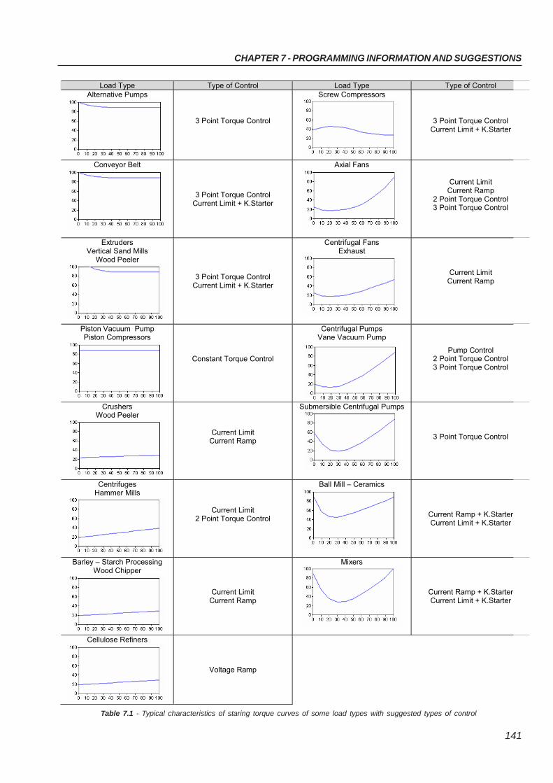
CHAPTER 7 - PROGRAMMING INFORMATION AND SUGGESTIONS
141
Table 7.1 - Typical characteristics of staring torque curves of some load types with suggested types of control
Load Type Type of Control Load Type Type of Control Alternative Pumps
3 Point Torque Control
Screw Compressors
3 Point Torque Control Current Limit + K.Starter
Conveyor Belt
3 Point Torque Control Current Limit + K.Starter
Axial Fans
Current Limit Current Ramp
2 Point Torque Control 3 Point Torque Control
Extruders Vertical Sand Mills
Wood Peeler
3 Point Torque Control Current Limit + K.Starter
Centrifugal Fans Exhaust
Current Limit Current Ramp
Piston Vacuum Pump Piston Compressors
Constant Torque Control
Centrifugal Pumps Vane Vacuum Pump
Pump Control 2 Point Torque Control 3 Point Torque Control
Crushers Wood Peeler
Current Limit Current Ramp
Submersible Centrifugal Pumps
3 Point Torque Control
Centrifuges Hammer Mills
Current Limit 2 Point Torque Control
Ball Mill – Ceramics
Current Ramp + K.Starter Current Limit + K.Starter
Barley – Starch Processing Wood Chipper
Current Limit Current Ramp
Mixers
Current Ramp + K.Starter Current Limit + K.Starter
Cellulose Refiners
Voltage Ramp
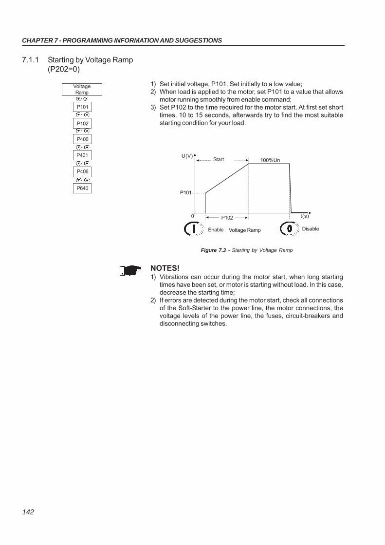
CHAPTER 7 - PROGRAMMING INFORMATION AND SUGGESTIONS
142
7.1.1 Starting by Voltage Ramp(P202=0)
1) Set initial voltage, P101. Set initially to a low value;2) When load is applied to the motor, set P101 to a value that allows
motor running smoothly from enable command;3) Set P102 to the time required for the motor start. At first set short
times, 10 to 15 seconds, afterwards try to find the most suitablestarting condition for your load.
Figure 7.3 - Starting by Voltage Ramp
NOTES!1) Vibrations can occur during the motor start, when long starting
times have been set, or motor is starting without load. In this case,decrease the starting time;
2) If errors are detected during the motor start, check all connectionsof the Soft-Starter to the power line, the motor connections, thevoltage levels of the power line, the fuses, circuit-breakers anddisconnecting switches.
U(V)Start 100%Un
P101
P1020
Enable Voltage Ramp
t(s)
P102
P101
VoltageRamp
P640
P406
P401
P400
Disable
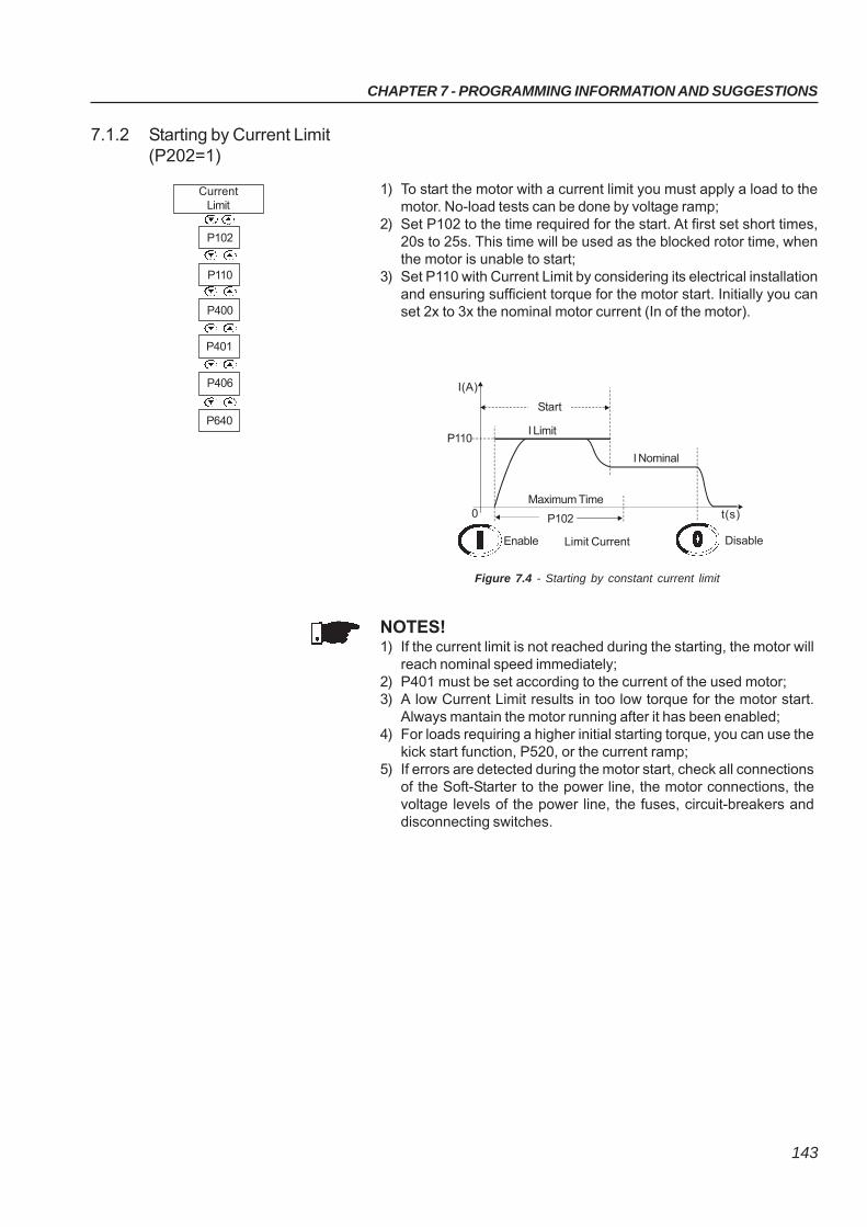
CHAPTER 7 - PROGRAMMING INFORMATION AND SUGGESTIONS
143
7.1.2 Starting by Current Limit(P202=1)
1) To start the motor with a current limit you must apply a load to themotor. No-load tests can be done by voltage ramp;
2) Set P102 to the time required for the start. At first set short times,20s to 25s. This time will be used as the blocked rotor time, whenthe motor is unable to start;
3) Set P110 with Current Limit by considering its electrical installationand ensuring sufficient torque for the motor start. Initially you canset 2x to 3x the nominal motor current (In of the motor).
Figure 7.4 - Starting by constant current limit
NOTES!1) If the current limit is not reached during the starting, the motor will
reach nominal speed immediately;2) P401 must be set according to the current of the used motor;3) A low Current Limit results in too low torque for the motor start.
Always mantain the motor running after it has been enabled;4) For loads requiring a higher initial starting torque, you can use the
kick start function, P520, or the current ramp;5) If errors are detected during the motor start, check all connections
of the Soft-Starter to the power line, the motor connections, thevoltage levels of the power line, the fuses, circuit-breakers anddisconnecting switches.
I(A)
Start
I Nominal
P110
P1020
Enable Limit Current Disable
t(s)
I Limit
Maximum Time
P110
P102
CurrentLimit
P640
P406
P401
P400
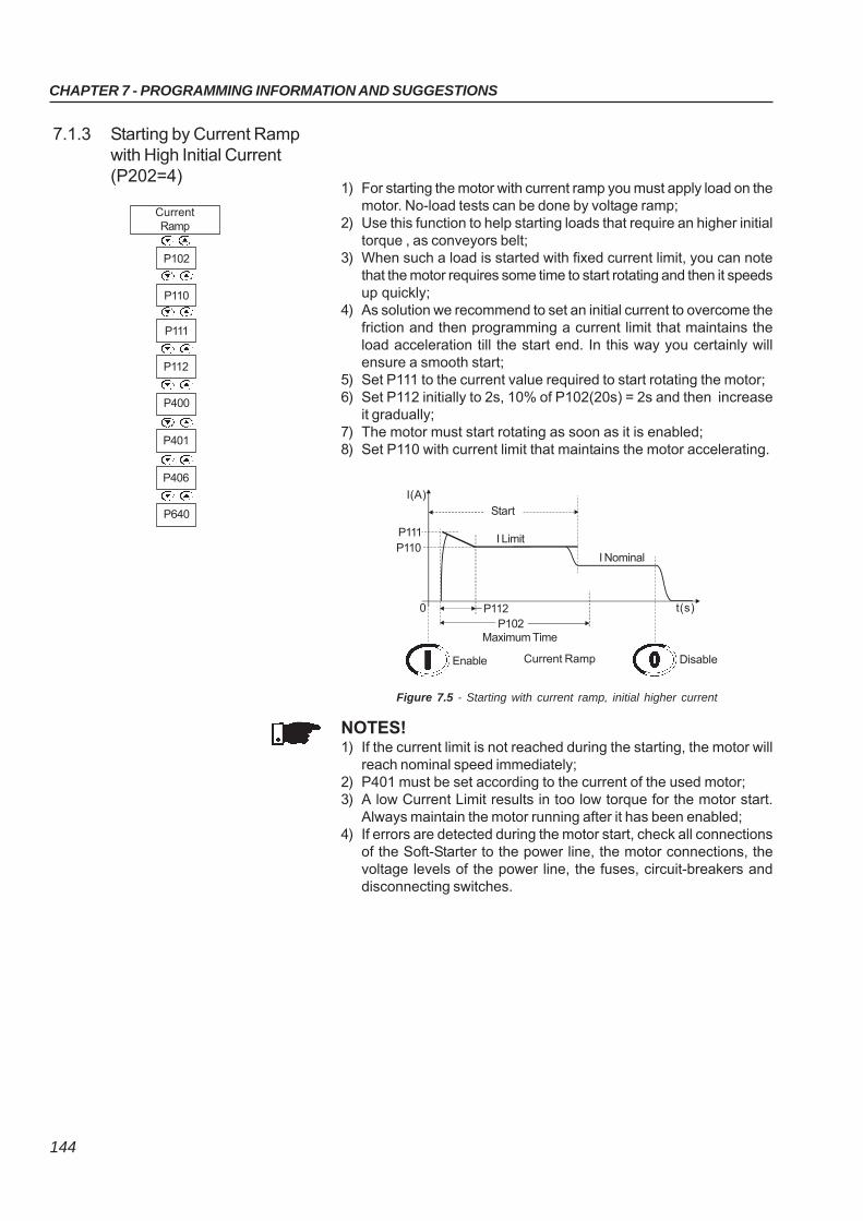
CHAPTER 7 - PROGRAMMING INFORMATION AND SUGGESTIONS
144
7.1.3 Starting by Current Rampwith High Initial Current(P202=4)
1) For starting the motor with current ramp you must apply load on themotor. No-load tests can be done by voltage ramp;
2) Use this function to help starting loads that require an higher initialtorque , as conveyors belt;
3) When such a load is started with fixed current limit, you can notethat the motor requires some time to start rotating and then it speedsup quickly;
4) As solution we recommend to set an initial current to overcome thefriction and then programming a current limit that maintains theload acceleration till the start end. In this way you certainly willensure a smooth start;
5) Set P111 to the current value required to start rotating the motor;6) Set P112 initially to 2s, 10% of P102(20s) = 2s and then increase
it gradually;7) The motor must start rotating as soon as it is enabled;8) Set P110 with current limit that maintains the motor accelerating.
Figure 7.5 - Starting with current ramp, initial higher current
NOTES!1) If the current limit is not reached during the starting, the motor will
reach nominal speed immediately;2) P401 must be set according to the current of the used motor;3) A low Current Limit results in too low torque for the motor start.
Always maintain the motor running after it has been enabled;4) If errors are detected during the motor start, check all connections
of the Soft-Starter to the power line, the motor connections, thevoltage levels of the power line, the fuses, circuit-breakers anddisconnecting switches.
I(A)
Start
I NominalP110
P1020
Enable Current Ramp Disable
t(s)
I Limit
Maximum Time
P111
P112
P110
P102
CurrentRamp
P401
P400
P112
P111
P640
P406
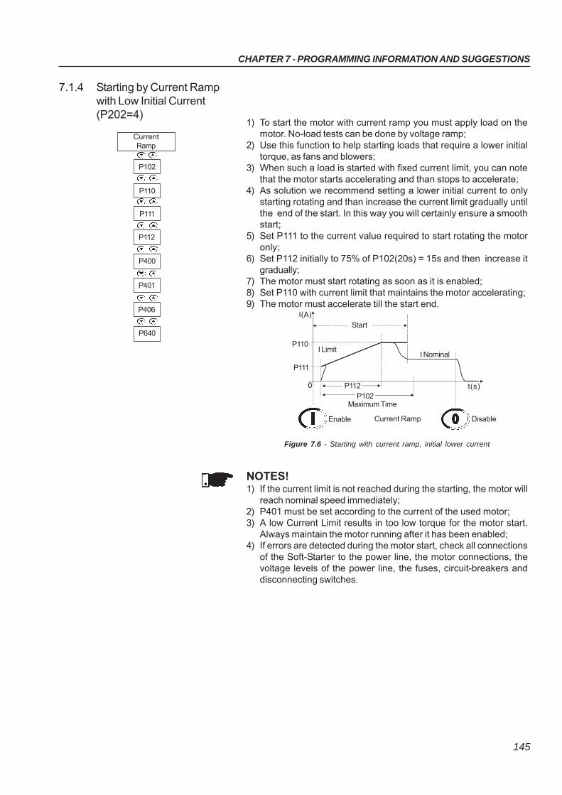
CHAPTER 7 - PROGRAMMING INFORMATION AND SUGGESTIONS
145
7.1.4 Starting by Current Rampwith Low Initial Current(P202=4)
1) To start the motor with current ramp you must apply load on themotor. No-load tests can be done by voltage ramp;
2) Use this function to help starting loads that require a lower initialtorque, as fans and blowers;
3) When such a load is started with fixed current limit, you can notethat the motor starts accelerating and than stops to accelerate;
4) As solution we recommend setting a lower initial current to onlystarting rotating and than increase the current limit gradually untilthe end of the start. In this way you will certainly ensure a smoothstart;
5) Set P111 to the current value required to start rotating the motoronly;
6) Set P112 initially to 75% of P102(20s) = 15s and then increase itgradually;
7) The motor must start rotating as soon as it is enabled;8) Set P110 with current limit that maintains the motor accelerating;9) The motor must accelerate till the start end.
Figure 7.6 - Starting with current ramp, initial lower current
NOTES!1) If the current limit is not reached during the starting, the motor will
reach nominal speed immediately;2) P401 must be set according to the current of the used motor;3) A low Current Limit results in too low torque for the motor start.
Always maintain the motor running after it has been enabled;4) If errors are detected during the motor start, check all connections
of the Soft-Starter to the power line, the motor connections, thevoltage levels of the power line, the fuses, circuit-breakers anddisconnecting switches.
I(A)Start
I NominalP110
P102
0
Enable Current Ramp Disable
t(s)
I Limit
Maximum Time
P111
P112
P110
P102
CurrentRamp
P401
P400
P112
P111
P640
P406
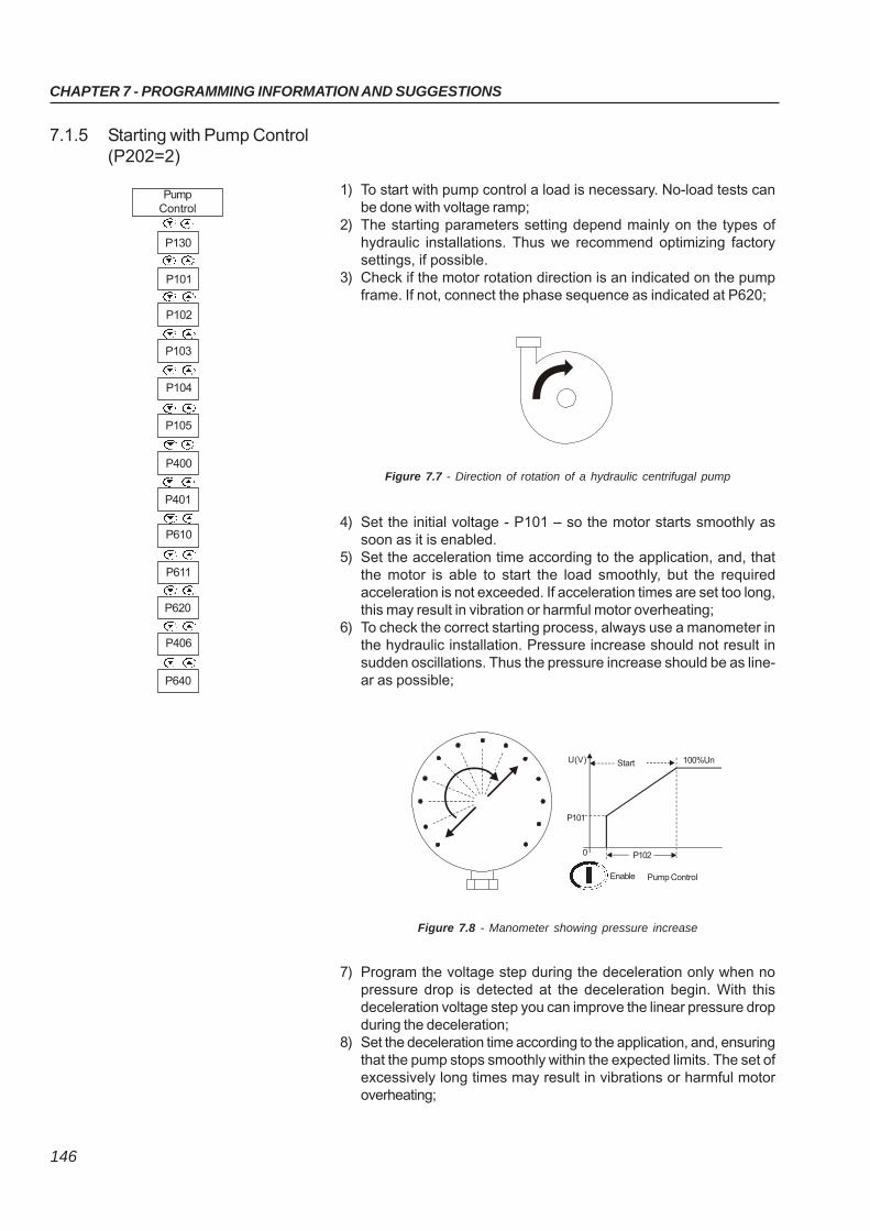
CHAPTER 7 - PROGRAMMING INFORMATION AND SUGGESTIONS
146
7.1.5 Starting with Pump Control(P202=2)
1) To start with pump control a load is necessary. No-load tests canbe done with voltage ramp;
2) The starting parameters setting depend mainly on the types ofhydraulic installations. Thus we recommend optimizing factorysettings, if possible.
3) Check if the motor rotation direction is an indicated on the pumpframe. If not, connect the phase sequence as indicated at P620;
Figure 7.7 - Direction of rotation of a hydraulic centrifugal pump
4) Set the initial voltage - P101 – so the motor starts smoothly assoon as it is enabled.
5) Set the acceleration time according to the application, and, thatthe motor is able to start the load smoothly, but the requiredacceleration is not exceeded. If acceleration times are set too long,this may result in vibration or harmful motor overheating;
6) To check the correct starting process, always use a manometer inthe hydraulic installation. Pressure increase should not result insudden oscillations. Thus the pressure increase should be as line-ar as possible;
7) Program the voltage step during the deceleration only when nopressure drop is detected at the deceleration begin. With thisdeceleration voltage step you can improve the linear pressure dropduring the deceleration;
8) Set the deceleration time according to the application, and, ensuringthat the pump stops smoothly within the expected limits. The set ofexcessively long times may result in vibrations or harmful motoroverheating;
Figure 7.8 - Manometer showing pressure increase
Enable
P102
Pump Control
0
P101
U(V) Start 100%Un
P611
P610
P401
P400
PumpControl
P105
P104
P103
P102
P101
P130
P640
P406
P620
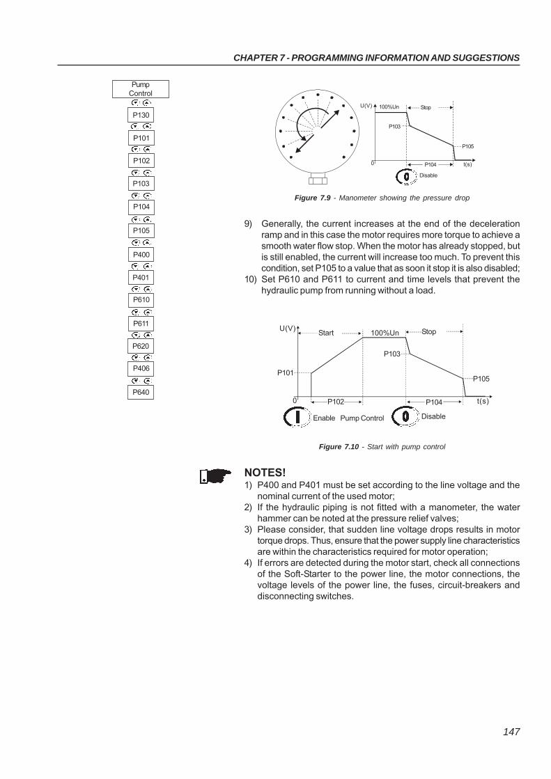
CHAPTER 7 - PROGRAMMING INFORMATION AND SUGGESTIONS
147
Figure 7.9 - Manometer showing the pressure drop
9) Generally, the current increases at the end of the decelerationramp and in this case the motor requires more torque to achieve asmooth water flow stop. When the motor has already stopped, butis still enabled, the current will increase too much. To prevent thiscondition, set P105 to a value that as soon it stop it is also disabled;
10) Set P610 and P611 to current and time levels that prevent thehydraulic pump from running without a load.
NOTES!1) P400 and P401 must be set according to the line voltage and the
nominal current of the used motor;2) If the hydraulic piping is not fitted with a manometer, the water
hammer can be noted at the pressure relief valves;3) Please consider, that sudden line voltage drops results in motor
torque drops. Thus, ensure that the power supply line characteristicsare within the characteristics required for motor operation;
4) If errors are detected during the motor start, check all connectionsof the Soft-Starter to the power line, the motor connections, thevoltage levels of the power line, the fuses, circuit-breakers anddisconnecting switches.
Figure 7.10 - Start with pump control
U(V)Start Stop
P101
P1020
Enable Disable
t(s)
100%Un
Pump Control
P103
P104
P105
Disable
P104 t(s)0
P103
U(V) Stop100%Un
P105
P611
P610
P401
P400
PumpControl
P105
P104
P103
P102
P101
P130
P640
P406
P620
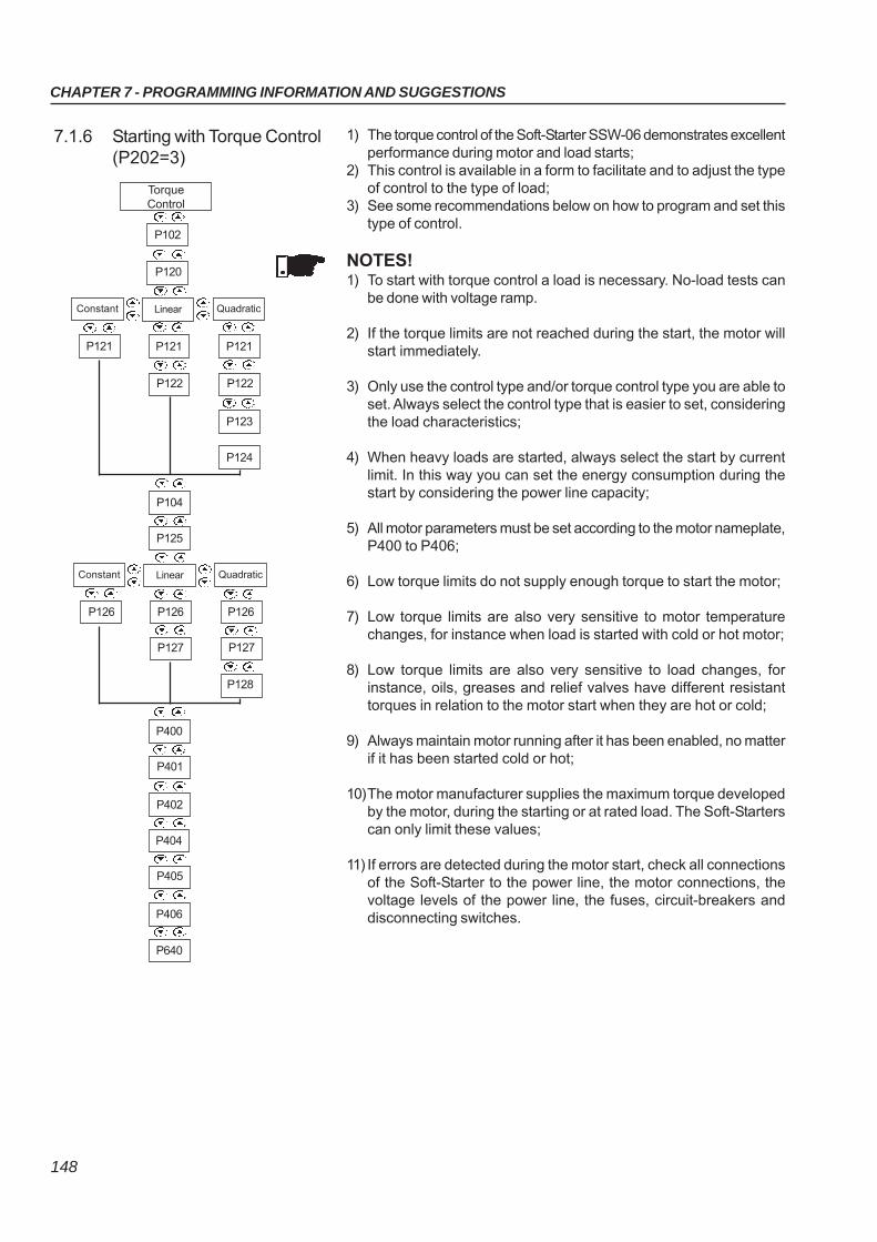
CHAPTER 7 - PROGRAMMING INFORMATION AND SUGGESTIONS
148
7.1.6 Starting with Torque Control(P202=3)
1) The torque control of the Soft-Starter SSW-06 demonstrates excellentperformance during motor and load starts;
2) This control is available in a form to facilitate and to adjust the typeof control to the type of load;
3) See some recommendations below on how to program and set thistype of control.
NOTES!1) To start with torque control a load is necessary. No-load tests can
be done with voltage ramp.
2) If the torque limits are not reached during the start, the motor willstart immediately.
3) Only use the control type and/or torque control type you are able toset. Always select the control type that is easier to set, consideringthe load characteristics;
4) When heavy loads are started, always select the start by currentlimit. In this way you can set the energy consumption during thestart by considering the power line capacity;
5) All motor parameters must be set according to the motor nameplate,P400 to P406;
6) Low torque limits do not supply enough torque to start the motor;
7) Low torque limits are also very sensitive to motor temperaturechanges, for instance when load is started with cold or hot motor;
8) Low torque limits are also very sensitive to load changes, forinstance, oils, greases and relief valves have different resistanttorques in relation to the motor start when they are hot or cold;
9) Always maintain motor running after it has been enabled, no matterif it has been started cold or hot;
10)The motor manufacturer supplies the maximum torque developedby the motor, during the starting or at rated load. The Soft-Starterscan only limit these values;
11) If errors are detected during the motor start, check all connectionsof the Soft-Starter to the power line, the motor connections, thevoltage levels of the power line, the fuses, circuit-breakers anddisconnecting switches.
TorqueControl
P120
P102
Constant Linear Quadratic
P123
P122
P121
P122
P121P121
P124
Constant Linear Quadratic
P128
P127
P126
P127
P126P126
P402
P401
P400
P406
P405
P404
P640
P104
P125
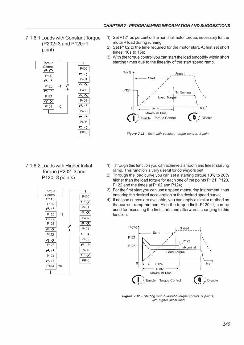
CHAPTER 7 - PROGRAMMING INFORMATION AND SUGGESTIONS
149
7.1.6.1 Loads with Constant Torque(P202=3 and P120=1point)
1) Set P121 as percent of the nominal motor torque, necessary for themotor + load during running;
2) Set P102 to the time required for the motor start. At first set shorttimes: 10s to 15s;
3) With the torque control you can start the load smoothly within shortstarting times due to the linearity of the start speed ramp.
Figure 7.11 - Start with constant torque control, 1 point
7.1.6.2 Loads with Higher InitialTorque (P202=3 andP120=3 points)
1) Through this function you can achieve a smooth and linear startingramp. This function is very useful for conveyors belt;
2) Through the load curve you can set a starting torque 10% to 20%higher than the load torque for each one of the points P121, P123,P122 and the times at P102 and P124;
3) For the first start you can use a speed measuring instrument, thusensuring the desired acceleration or the desired speed curve;
4) If no load curves are available, you can apply a similar method asthe current ramp method. Also the torque limit, P120=1, can beused for executing the first starts and afterwards changing to thisfunction.
Figure 7.12 - Starting with quadratic torque control, 3 points,with higher initial load
Tn(%)
StartSpeed
P1020
Enable Disable
t(s)
Maximum Time
P121Tn Nominal
Load Torque
Torque Control
P120 =1
P102
TorqueControl
P401
P400
P104 =0
P121
P640
P406
P404
P402
P405
Tn(%)
StartSpeed
P1240
Enable Disable
t(s)
Maximum Time
P121
Tn Nominal
Load Torque
Torque Control
P123
P102
P122
P120 =3
P102
TorqueControl
P401
P400
P122
P121
P640
P406
P404
P402
P405
P123
P124
P104 =0
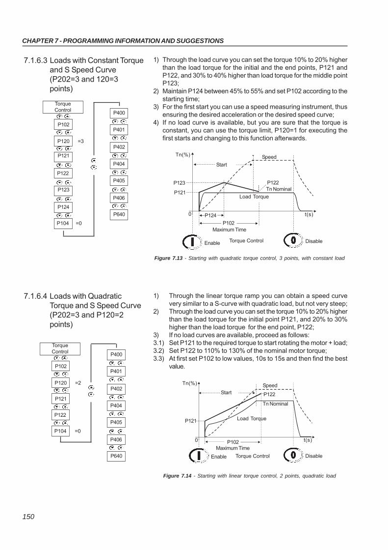
CHAPTER 7 - PROGRAMMING INFORMATION AND SUGGESTIONS
150
7.1.6.3 Loads with Constant Torqueand S Speed Curve(P202=3 and 120=3points)
1) Through the load curve you can set the torque 10% to 20% higherthan the load torque for the initial and the end points, P121 andP122, and 30% to 40% higher than load torque for the middle pointP123;
2) Maintain P124 between 45% to 55% and set P102 according to thestarting time;
3) For the first start you can use a speed measuring instrument, thusensuring the desired acceleration or the desired speed curve;
4) If no load curve is available, but you are sure that the torque isconstant, you can use the torque limit, P120=1 for executing thefirst starts and changing to this function afterwards.
Figure 7.13 - Starting with quadratic torque control, 3 points, with constant load
7.1.6.4 Loads with QuadraticTorque and S Speed Curve(P202=3 and P120=2points)
1) Through the linear torque ramp you can obtain a speed curvevery similar to a S-curve with quadratic load, but not very steep;
2) Through the load curve you can set the torque 10% to 20% higherthan the load torque for the initial point P121, and 20% to 30%higher than the load torque for the end point, P122;
3) If no load curves are available, proceed as follows:3.1) Set P121 to the required torque to start rotating the motor + load;3.2) Set P122 to 110% to 130% of the nominal motor torque;3.3) At first set P102 to low values, 10s to 15s and then find the best
value.
Figure 7.14 - Starting with linear torque control, 2 points, quadratic load
Tn(%)
Start
Speed
P1240
Enable Disable
t(s)
Maximum Time
P121Tn Nominal
Load Torque
Torque Control
P123
P102
P122
P120 =3
P102
TorqueControl
P401
P400
P122
P121
P640
P406
P404
P402
P405
P123
P124
P104 =0
Tn(%)
StartSpeed
0
Enable Disable
t(s)
Maximum Time
P121
Tn Nominal
Load Torque
Torque Control
P102
P122
P401
P400
P640
P406
P404
P402
P405
P120 =2
P102
TorqueControl
P122
P121
P104 =0
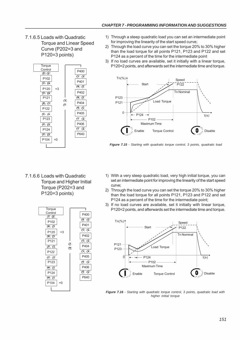
CHAPTER 7 - PROGRAMMING INFORMATION AND SUGGESTIONS
151
7.1.6.5 Loads with QuadraticTorque and Linear SpeedCurve (P202=3 andP120=3 points)
1) Through a steep quadratic load you can set an intermediate pointfor improving the linearity of the start speed curve;
2) Through the load curve you can set the torque 20% to 30% higherthan the load torque for all points P121, P123 and P122 and setP124 as a percent of the time for the intermediate point
3) If no load curves are available, set it initially with a linear torque,P120=2 points, and afterwards set the intermediate time and torque.
Figure 7.15 - Starting with quadratic torque control, 3 points, quadratic load
7.1.6.6 Loads with QuadraticTorque and Higher InitialTorque (P202=3 andP120=3 points)
1) With a very steep quadratic load, very high initial torque, you canset an intermediate point for improving the linearity of the start speedcurve;
2) Through the load curve you can set the torque 20% to 30% higherthan the load torque for all points P121, P123 and P122 and setP124 as a percent of the time for the intermediate point;
3) If no load curves are available, set it initially with linear torque,P120=2 points, and afterwards set the intermediate time and torque.
Figure 7.16 - Starting with quadratic torque control, 3 points, quadratic load withhigher initial torque
Tn(%)
StartSpeed
P1240
Enable Disable
t(s)
Maximum Time
P121
Tn Nominal
Load Torque
Torque Control
P123
P102
P122
Tn(%)
Start
Speed
P1240
Enable Disable
t(s)
Maximum Time
P121
Tn Nominal
Load Torque
Torque Control
P123
P102
P122
P120 =3
P102
TorqueControl
P401
P400
P122
P121
P640
P406
P404
P402
P405
P123
P124
P104 =0
P120 =3
P102
TorqueControl
P401
P400
P122
P121
P640
P406
P404
P402
P405
P123
P124
P104 =0
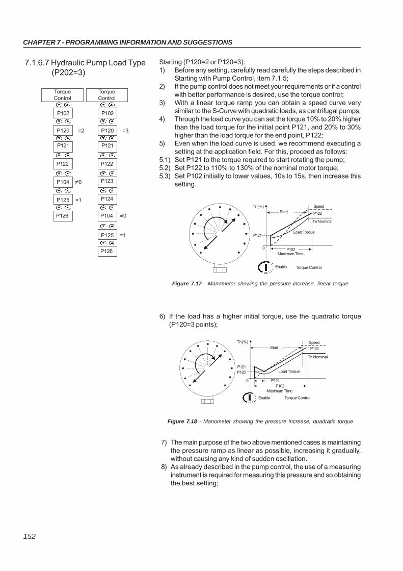
CHAPTER 7 - PROGRAMMING INFORMATION AND SUGGESTIONS
152
7.1.6.7 Hydraulic Pump Load Type(P202=3)
Starting (P120=2 or P120=3):1) Before any setting, carefully read carefully the steps described in
Starting with Pump Control, item 7.1.5;2) If the pump control does not meet your requirements or if a control
with better performance is desired, use the torque control;3) With a linear torque ramp you can obtain a speed curve very
similar to the S-Curve with quadratic loads, as centrifugal pumps;4) Through the load curve you can set the torque 10% to 20% higher
than the load torque for the initial point P121, and 20% to 30%higher than the load torque for the end point, P122;
5) Even when the load curve is used, we recommend executing asetting at the application field. For this, proceed as follows:
5.1) Set P121 to the torque required to start rotating the pump;5.2) Set P122 to 110% to 130% of the nominal motor torque;5.3) Set P102 initially to lower values, 10s to 15s, then increase this
setting.
7) The main purpose of the two above mentioned cases is maintainingthe pressure ramp as linear as possible, increasing it gradually,without causing any kind of sudden oscillation.
8) As already described in the pump control, the use of a measuringinstrument is required for measuring this pressure and so obtainingthe best setting;
Figure 7.17 - Manometer showing the pressure increase, linear torque
6) If the load has a higher initial torque, use the quadratic torque(P120=3 points);
Figure 7.18 - Manometer showing the pressure increase, quadratic torque
Tn(%)Start
P121
0 P102Maximum Time
Torque ControlEnable
Load Torque
Tn Nominal
Speed
P122
Tn(%)Start
P121
0P102
Torque ControlEnable
Load Torque
Tn Nominal
Speed
P122
P123
Maximum Time
P124
P120 =3
TorqueControl
P122
P123
P104 0
P124
P120 =2
P102
TorqueControl
P122
P121
P104 ≠0
P126
P125 =1
≠
P102
P121
P126
P125 =1
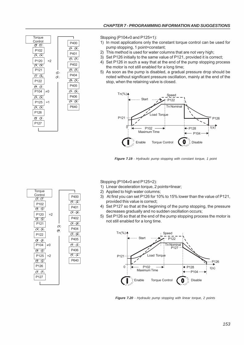
CHAPTER 7 - PROGRAMMING INFORMATION AND SUGGESTIONS
153
Stopping (P104≠0 and P125=1):1) In most applications only the constant torque control can be used for
pump stopping, 1 point=constant;2) This method is used for water columns that are not very high;3) Set P126 initially to the same value of P121, provided it is correct;4) Set P126 in such a way that at the end of the pump stopping process
the motor is not still enabled for a long time;5) As soon as the pump is disabled, a gradual pressure drop should be
noted without significant pressure oscillation, mainly at the end of thestop, when the retaining valve is closed.
Figure 7.19 - Hydraulic pump stopping with constant torque, 1 point
Stopping (P104≠0 and P125=2):1) Linear deceleration torque, 2 points=linear;2) Applied to high water columns;3) At first you can set P126 for 10% to 15% lower than the value of P121,
provided this value is correct;4) Set P127 so that at the beginning of the pump stopping, the pressure
decreases gradually and no sudden oscillation occurs;5) Set P126 so that at the end of the pump stopping process the motor is
not still enabled for a long time.
Figure 7.20 - Hydraulic pump stopping with linear torque, 2 points
Tn(%)
StartSpeed
0
Enable Disable
t(s)Maximum Time
P121
Tn Nominal
Load Torque
Torque Control
P102
P122
P128
P104
P126
P401
P400
P640
P406
P404
P402
P405
P120 =2
P102
TorqueControl
P122
P121
P104 0
P125 =1
P126
P127
≠
Tn(%)
Start
Speed
0
Enable Disable
t(s)Maximum Time
P121
Tn Nominal
Load Torque
Torque Control
P102
P122
P128
P127
P104
P126
P401
P400
P640
P406
P404
P402
P405
P120 =2
P102
TorqueControl
P122
P121
P104 0
P125 =2
P126
P127
≠
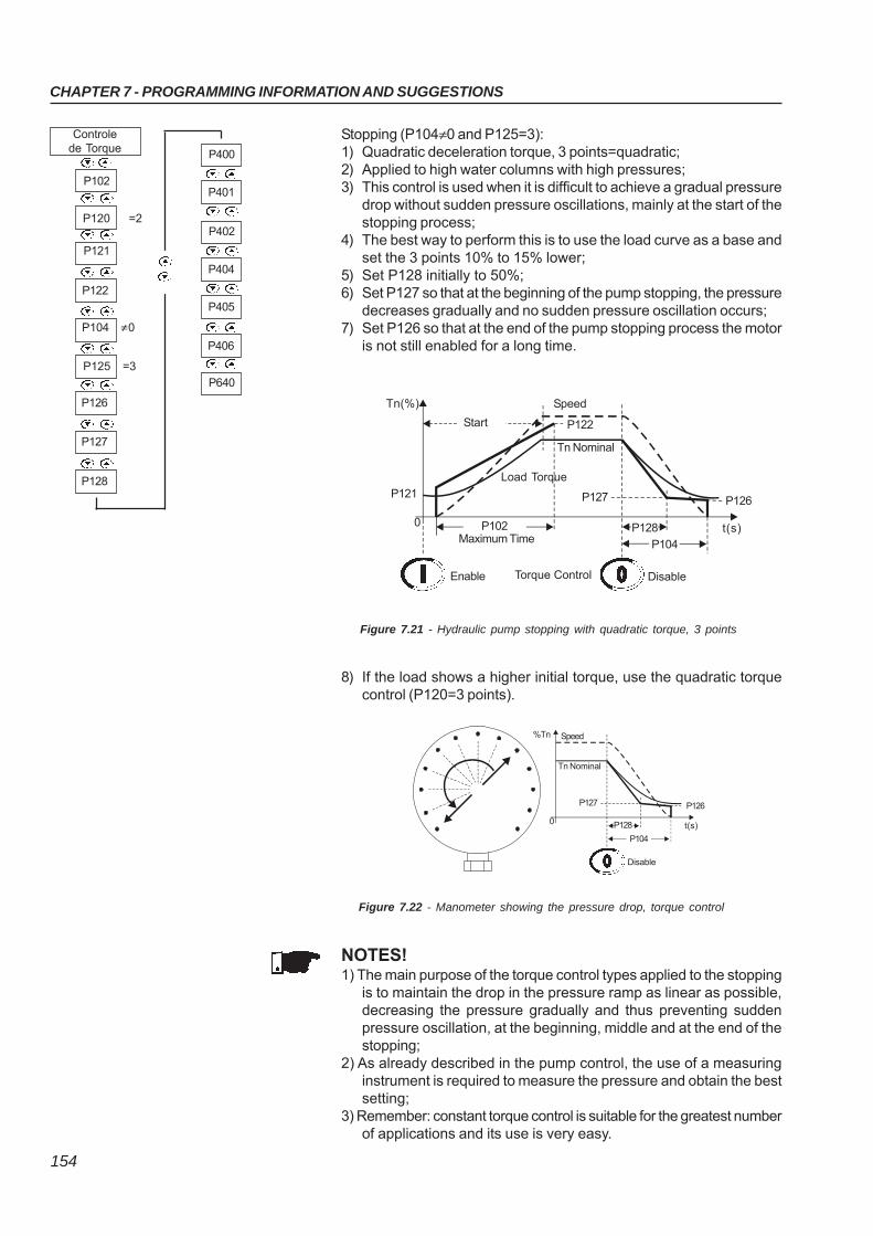
CHAPTER 7 - PROGRAMMING INFORMATION AND SUGGESTIONS
154
Stopping (P104≠0 and P125=3):1) Quadratic deceleration torque, 3 points=quadratic;2) Applied to high water columns with high pressures;3) This control is used when it is difficult to achieve a gradual pressure
drop without sudden pressure oscillations, mainly at the start of thestopping process;
4) The best way to perform this is to use the load curve as a base andset the 3 points 10% to 15% lower;
5) Set P128 initially to 50%;6) Set P127 so that at the beginning of the pump stopping, the pressure
decreases gradually and no sudden pressure oscillation occurs;7) Set P126 so that at the end of the pump stopping process the motor
is not still enabled for a long time.
Figure 7.21 - Hydraulic pump stopping with quadratic torque, 3 points
8) If the load shows a higher initial torque, use the quadratic torquecontrol (P120=3 points).
Figure 7.22 - Manometer showing the pressure drop, torque control
NOTES!1) The main purpose of the torque control types applied to the stopping
is to maintain the drop in the pressure ramp as linear as possible,decreasing the pressure gradually and thus preventing suddenpressure oscillation, at the beginning, middle and at the end of thestopping;
2) As already described in the pump control, the use of a measuringinstrument is required to measure the pressure and obtain the bestsetting;
3) Remember: constant torque control is suitable for the greatest numberof applications and its use is very easy.
Tn(%)
Start
Speed
P1280
Enable Disable
t(s)Maximum Time
P121
Tn Nominal
Load Torque
Torque Control
P102
P122
P104
P126P127
%Tn
0
P104
Tn Nominal
Speed
P127
P128
P126
t(s)
Disable
P401
P400
P640
P406
P404
P402
P405
P120 =2
P102
Controlede Torque
P122
P121
P104 0
P125 =3
P126
P127
≠
P128
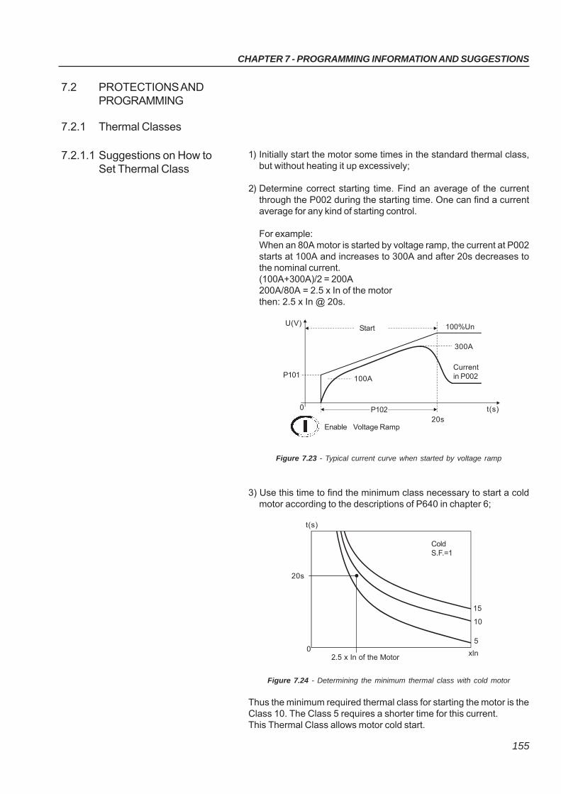
CHAPTER 7 - PROGRAMMING INFORMATION AND SUGGESTIONS
155
1) Initially start the motor some times in the standard thermal class,but without heating it up excessively;
2) Determine correct starting time. Find an average of the currentthrough the P002 during the starting time. One can find a currentaverage for any kind of starting control.
For example:When an 80A motor is started by voltage ramp, the current at P002starts at 100A and increases to 300A and after 20s decreases tothe nominal current.(100A+300A)/2 = 200A200A/80A = 2.5 x In of the motorthen: 2.5 x In @ 20s.
7.2 PROTECTIONS ANDPROGRAMMING
7.2.1 Thermal Classes
7.2.1.1 Suggestions on How toSet Thermal Class
Figure 7.23 - Typical current curve when started by voltage ramp
3) Use this time to find the minimum class necessary to start a coldmotor according to the descriptions of P640 in chapter 6;
Figure 7.24 - Determining the minimum thermal class with cold motor
Thus the minimum required thermal class for starting the motor is theClass 10. The Class 5 requires a shorter time for this current.This Thermal Class allows motor cold start.
U(V)Start 100%Un
20s
0
Enable
t(s)
P101
Voltage Ramp
P102
Currentin P002100A
300A
t(s)
0
20s
2.5 x In of the Motor
5
10
xln
15
ColdS.F.=1
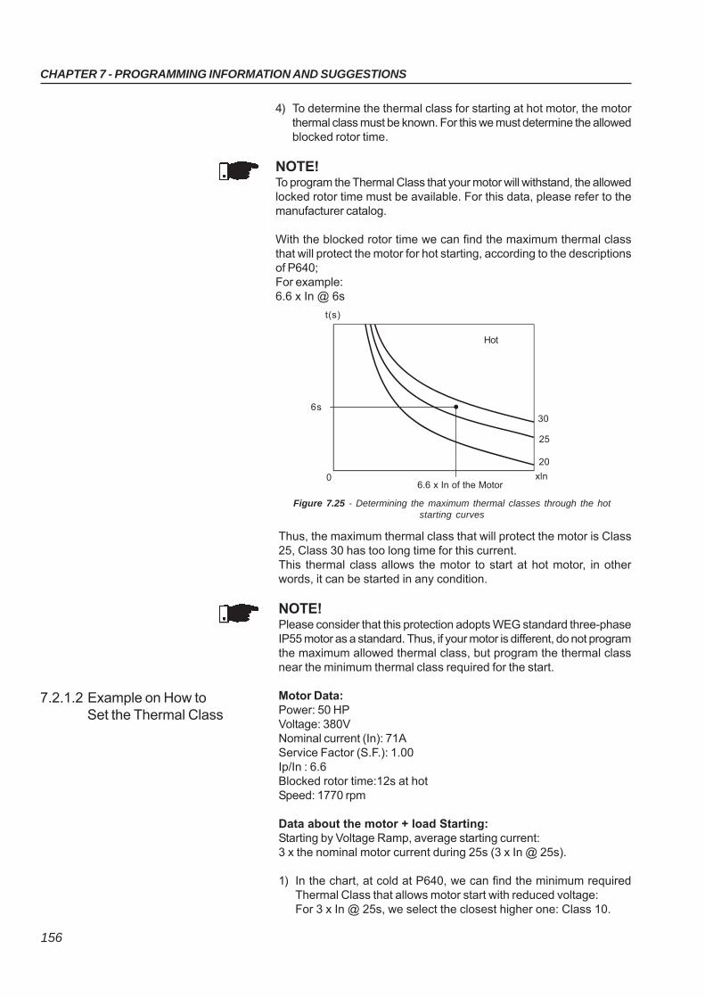
CHAPTER 7 - PROGRAMMING INFORMATION AND SUGGESTIONS
156
4) To determine the thermal class for starting at hot motor, the motorthermal class must be known. For this we must determine the allowedblocked rotor time.
NOTE!To program the Thermal Class that your motor will withstand, the allowedlocked rotor time must be available. For this data, please refer to themanufacturer catalog.
With the blocked rotor time we can find the maximum thermal classthat will protect the motor for hot starting, according to the descriptionsof P640;For example:6.6 x In @ 6s
Figure 7.25 - Determining the maximum thermal classes through the hotstarting curves
Thus, the maximum thermal class that will protect the motor is Class25, Class 30 has too long time for this current.This thermal class allows the motor to start at hot motor, in otherwords, it can be started in any condition.
NOTE!Please consider that this protection adopts WEG standard three-phaseIP55 motor as a standard. Thus, if your motor is different, do not programthe maximum allowed thermal class, but program the thermal classnear the minimum thermal class required for the start.
Motor Data:Power: 50 HPVoltage: 380VNominal current (In): 71AService Factor (S.F.): 1.00Ip/In : 6.6Blocked rotor time:12s at hotSpeed: 1770 rpm
Data about the motor + load Starting:Starting by Voltage Ramp, average starting current:3 x the nominal motor current during 25s (3 x In @ 25s).
1) In the chart, at cold at P640, we can find the minimum requiredThermal Class that allows motor start with reduced voltage:For 3 x In @ 25s, we select the closest higher one: Class 10.
7.2.1.2 Example on How toSet the Thermal Class
t(s)
0
6s
6.6 x In of the Motor
20
25
xln
30
Hot
CHAPTER 7 - PROGRAMMING INFORMATION AND SUGGESTIONS
157
7.2.1.3 Time Reduction WhenChanging from ColdStarting to Hot Starting
7.2.1.4 Service Factor
Figure 7.26 - Using the S.F. to find new times
t(s)
0 xInof the Motor
15
20
25
Cold
S.F.=1.15
S.F.=1.25
2x 3x 4x
2) In the chart, at hot in P640, we can find the maximum ThermalClass that the motor will withstand due to the locked rotor time athot:For 6.6 x In @ 12s, we select the closest lower Class: Class 40.
Now it is known that Thermal Class 10 allows one start and ThermalClass 40 is the upper limit. Thus you must select a Thermal Classbetween these two Thermal Classes by considering the number of startsper hour and the time interval between motor Off-On procedures.
The closer to Class 10 you select, more protected will be your motor,less starts per hour are allowed and longer time intervals betweenmotor Off-On procedures are required.
The closer to Class 40 you select, you will be nearer the upper motorlimit, thus more starts per hour are allowed and shorter time intervalsbetween motor Off-On procedures can be used.
To determine the activation times of the hot Thermal Classes, whenthe motor is running at rated load with current lower than 100% of theIn, use the multiplier factor shown in table 6.46 at P640, as a percentageof the current that the motor is absorbing when running continuously.
For example:A motor is running with 80% In and then is switched Off.It is switched On again immediately.The starting current is 3xIn @ 25s.The selected Thermal Class, in the table 6.43, is the Class 10 with33.7s @ 3xIn.As shown in table 6.46, the correction factor for 80% In is 0.48.
The final activation time will be: 0.48 x 33.7s = 16.2s, and, the time isreduced at cold start from 33.7s to 16.2s at hot start. Thus, a newmotor start is not allowed before the thermal motor image decreases,the motor cools down.
When the Service factor (S.F.) is different from 1.00, but its use isrequired, you can find in the chart, at cold, the points for the S.F. =1.15 and a table for S.F. = 1.15, see P640.
If you want to know the thermal protection activation time for otherService Factor (S.F.), displace the line xIn proportionally to the left.
CHAPTER 7 - PROGRAMMING INFORMATION AND SUGGESTIONS
158
In order to make the setting easier, all the under- and over- protectionsof the SSW-06 are adjusted in percentage of the motor nominal values.
These functions are normally used for the motor protection.Initially the following data are necessary:
1) Nominal motor voltage adjusted in P400, it is a motor nameplatedata.
2) The voltage variation tolerated by the motor, it is a motor manufacturercatalog data, normally from -15% to +10% of the nominal voltage.
Setting example:Nominal motor voltage of 380V,Voltage tolerance from -15% to +10%.P400=380VP600=15%P602=10%Therefore, when there is a voltage drop deeper than 15% in the supplyvoltage, regarding the nominal voltage, the undervoltage protection willtrip. And when there is a voltage increase higher than 10% in the supplyvoltage, regarding the nominal voltage, the overvoltage protection willtrip.
It is normally used for the detection of no load pump; it can also beused for the detection of loads under the minimum allowed value.
It can be configured according to the needs and knowledge of theuser among: Undercurrent, Undertorque or Underpower. All thesefunctions present the same form of protection; however, Undertorqueand Underpower are more sensitive and detect variations in both voltageand current.
Example of Undercurrent setting:Nominal motor current of 100A.There is a normal ±10A load oscillation in this application.Without load it drops to 60A.In percentage:There is a normal load oscillation of ±10% of the nominal motor current.There is a 40% drop in the nominal motor current for the no loadcondition.In order to get Underload detection, the Undercurrent protection mustbe programmed between 10% and 40% (30% for instance):P401=100AP610=30%P611=1sTherefore, when there is a drop bigger than 30% in the motor current,regarding the nominal current, the protection will trip.
The same sequence demonstrated above is valid also for Undertorqueand Underpower; however the respective parameters for the desiredfunction must be adjusted.
It can be configured according to the needs and knowledge of theuser among: Overcurrent, Overtorque or Overpower. All these functionspresent the same form of protection; however, Overtorque and Overpowerare more sensitive and detect variations in both voltage and current.
7.2.2 Under- andOver- Protections
7.2.2.1 Undervoltage andOvervoltage protection
7.2.2.2 Underload Protection
7.2.2.3 Overload Protection
CHAPTER 7 - PROGRAMMING INFORMATION AND SUGGESTIONS
159
Example of Overcurrent setting:Nominal motor current of 100A.There is a normal ±10A load oscillation in this application.The motor Service Factor (S.F.) is 1.15.In percentage:There is a normal load oscillation of ±10% of the nominal motor current.The motor tolerates a 15% overload according to the S.F.In order to get Overload protection, the Overcurrent protection can beprogrammed higher than 15%.P401=100AP612=20%P613=1sTherefore, when there is an increase higher than 20% in the motorcurrent, regarding the nominal current, the protection will trip.
The same sequence demonstrated above is valid also for Overtorqueand Overpower; however the respective parameters for the desiredfunction must be adjusted.
160
CHAPTER 8
DIAGNOSTICS AND TROUBLESHOOTING
This Chapter helps the user to identify and correct possible faults thatcan occur during the Soft-Starter SSW-06 operation. This Chapter alsoprovides instructions about periodical inspections and cleaningrequirements.
8.1 FAULTS AND POSSIBLECAUSES
FAULT
E03Undervoltage atpower section duringoperation
Phase loss orvoltage imbalancein the power sectionduring operation
Phase loss in thepower at start
E04Soft-Starterovertemperature
E05 or A05Motor overload
E06 or A06External fault or Alarm
E10Error in the copyfunction
DESCRIPTION OF THE ACTUATION
When the voltage between phases is lowerthan the programmed value during theprogrammed time. The nominal motor voltageis used as a reference.
When the voltage between phases islower or higher than the programmed valueduring the programmed time, or whenphase loss has been detected. The othertwo motor phases are used as reference.
When there is no voltage synchronizationpulse at start.
When the thermostats of the heatsink act.
When the times given by the curves of theprogrammed thermal classes exceed theprogrammed values.
When the digital input programmed to NoExternal Fault opens, P266, P267 or P268.
When the Keypad has been loaded withparameters of a different version to theswitch.
POSSIBLE CAUSES
The line undervoltage value (in percentage of P400)is higher than the programmed in P600, longer thanthe time programmed in P601.The value of the voltage imbalance between the linephases (in percentage of P400) is higher than theprogrammed in P604, longer than the timeprogrammed in P605.Voltage drop during start.Phase loss in the power supply.Input transformers have been undersized.Actuation problems with input contactor.Fuses at input are open.Loose contact in the power supply connections.Wrong motor connection.
Panel with unsuitable cooling.Start cycles not permitted.
Start cycles not permitted.Thermal classes are programmed in P640 lowerthan permitted by the motor duty.Off/On intervals shorter than required for themotor cooling.The value of the thermal protection saved whenswitching off returns when switched on again.
DI4...DI6 wiring is open or not connected to +24V.X1 connector of the CCS6 control board isdisconnected.
A bid to copy the keypad parameters to aSoft-Starter with different Software version.
RESET
Power-onManual ResetAuto-resetDIx
Power-onManual ResetAuto-resetDIx
Power-onManual ResetAuto-resetDIx
Power-onManual ResetAuto-resetDIx
Power-onManual ResetDIx
When most of the errors are detected, the motor is switched off and theerror is shown on the display as EXY, XY being the error code.For the SSW-06 Soft-Starter to return to normal operation after an error,it is necessary to reset it. This can generally be done in the followingways: Disconnecting and reapplying AC power (power-on reset); Pressing the of the keypad - (manual reset); Automatic reset through P206 setting (auto-reset); Via digital input: DI2 (P264 = 2) or DI3 (P265 = 2) or DI4 (P266 = 6)
or DI5 (P267 = 6) or DI6 (P268 = 6).The fault trips can be transformed into alarms by means of P700 toP799. The alarms are showed on the display as Axy, being Axy thefault code. They are automatically reset.
The table below shows the reset details for each possible cause.
Table 8.1 - Detailed fault description
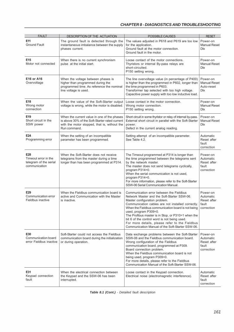
CHAPTER 8 - DIAGNOSTICS AND TROUBLESHOOTING
161
FAULT
E11Ground Fault
E15Motor not connected
E16 or A16Overvoltage
E18Wrong motorconnection
E19Short circuit in theSSW power
E24Programming error
E28Timeout error in thetelegram of the serialcommunication
E29Communication errorFieldbus inactive
E30Communication boarderror Fieldbus inactive
E31Keypad connectionfault
DESCRIPTION OF THE ACTUATION
The ground fault is detected through theinstantaneous imbalance between the supplyphases current.
When there is no current synchronismpulse at the initial start.
When the voltage between phases ishigher than programmed during theprogrammed time. As reference the nominalline voltage is used.
When the value of the Soft-Starter outputvoltage is wrong, while the motor is disabled.
When the current value in one of the phasesis above 30% of the Soft-Starter rated currentwith the motor stopped, that is, without theRun command.
When the setting of an incompatibleparameter has been programmed.
When the Soft-Starter does not receivetelegrams from the master during a timelonger than has been programmed at P314.
When the Fieldbus communication board isactive and Communication with the Masteris inactive.
Soft-Starter could not access the Fieldbuscommunication board during the initializationor during operation.
When the electrical connection betweenthe Keypad and the SSW-06 has beeninterrupted.
POSSIBLE CAUSES
The values adjusted in P618 and P619 are too lowfor the application.Ground fault at the motor connection.Ground fault in the motor.
Loose contact of the motor connections.Thyristors or internal By-pass relays areshort-circuited.P150 setting wrong.
The line overvoltage value (in percentage of P400)is higher than the programmed in P602, longer thanthe time programmed in P603.Transformer tap selected with too high voltage.Capacitive power supply with too low inductive load.
Loose contact in the motor connection.Wrong motor connection.P150 setting wrong.
Short circuit in some thyristor or relay of internal by-pass.External short circuit in parallel with the Soft-Starterpower.Defect in the current analog reading.
Setting attempt of an incompatible parameter.See Table 4.2.
The Timeout programmed at P314 is longer thanthe time programmed between the telegrams sentby the network master.The master does not send telegrams cyclically,program P314=0.When the serial communication is not used,program P314=0.For more information, please refer to the Soft-StarterSSW-06 Serial Communication Manual.
Communication error between the FieldbusNetwork Master and the Soft-Starter SSW-06.Master configuration problem.Communication cables are not installed correctly.When the Fieldbus communication board is not beingused, program P309=0.The Profibus master is in Stop, or P310=1 when thebit 6 of the control word is not being used.For more details, please refer to the FieldbusCommunication Manual of the Soft-Starter SSW-06.
Data exchange problems between the Soft-StarterSSW-06 and the Fieldbus communication board.Wrong configuration of the Fieldbuscommunication board, programmed at P309.Board connection problem.When the Fieldbus communication board is notbeing used, program P309=0.For more details, please refer to the FieldbusCommunication Manual of the Soft-Starter SSW-06.
Loose contact in the Keypad connection.Electrical noise (electromagnetic interference).
RESET
Power-onManual ResetDIx
Power-onManual ResetDIx
Power-onManual ResetAuto-resetDIx
Power-onManual ResetDIx
Power-onManual ResetDIx
AutomaticReset afterfaultcorrection
Power-onAutomaticReset afterfaultcorrection
Power-onAutomaticReset afterfaultcorrection
Power-onAutomaticReset afterfaultcorrection
AutomaticReset afterfaultcorrection
Table 8.1 (Cont.) - Detailed fault description
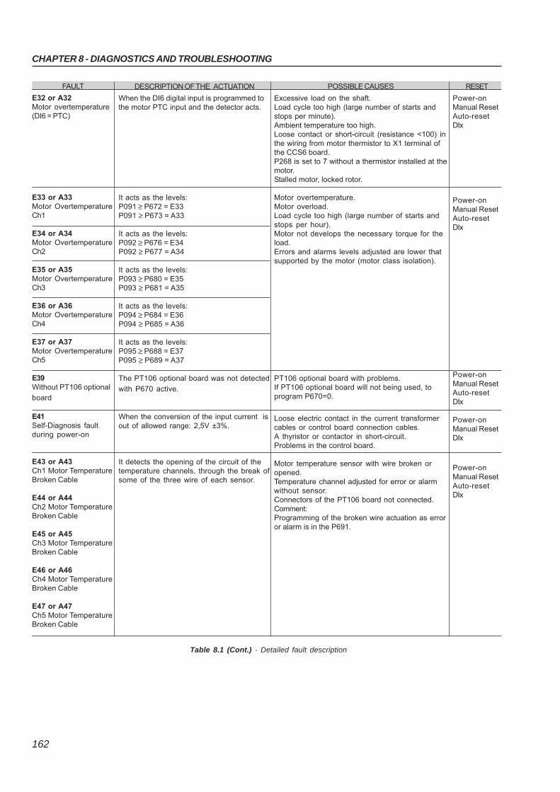
CHAPTER 8 - DIAGNOSTICS AND TROUBLESHOOTING
162
DESCRIPTION OF THE ACTUATION
When the DI6 digital input is programmed tothe motor PTC input and the detector acts.
It acts as the levels:P091 ≥ P672 = E33P091 ≥ P673 = A33
It acts as the levels:P092 ≥ P676 = E34P092 ≥ P677 = A34
It acts as the levels:P093 ≥ P680 = E35P093 ≥ P681 = A35
It acts as the levels:P094 ≥ P684 = E36P094 ≥ P685 = A36
It acts as the levels:P095 ≥ P688 = E37P095 ≥ P689 = A37
The PT106 optional board was not detected
with P670 active.
When the conversion of the input current isout of allowed range: 2,5V ±3%.
It detects the opening of the circuit of thetemperature channels, through the break ofsome of the three wire of each sensor.
POSSIBLE CAUSES
Excessive load on the shaft.Load cycle too high (large number of starts andstops per minute).Ambient temperature too high.Loose contact or short-circuit (resistance <100) inthe wiring from motor thermistor to X1 terminal ofthe CCS6 board.P268 is set to 7 without a thermistor installed at themotor.Stalled motor, locked rotor.
Motor overtemperature.Motor overload.Load cycle too high (large number of starts andstops per hour).Motor not develops the necessary torque for theload.Errors and alarms levels adjusted are lower thatsupported by the motor (motor class isolation).
PT106 optional board with problems.If PT106 optional board will not being used, toprogram P670=0.
Loose electric contact in the current transformercables or control board connection cables.A thyristor or contactor in short-circuit.Problems in the control board.
Motor temperature sensor with wire broken oropened.Temperature channel adjusted for error or alarmwithout sensor.Connectors of the PT106 board not connected.Comment:Programming of the broken wire actuation as erroror alarm is in the P691.
RESET
Power-onManual ResetAuto-resetDIx
Power-onManual ResetAuto-resetDIx
Power-onManual ResetAuto-resetDIx
Power-onManual ResetDIx
Power-onManual ResetAuto-resetDIx
Table 8.1 (Cont.) - Detailed fault description
FAULT
E32 or A32Motor overtemperature(DI6 = PTC)
E33 or A33Motor OvertemperatureCh1
E34 or A34Motor OvertemperatureCh2
E35 or A35Motor OvertemperatureCh3
E36 or A36Motor OvertemperatureCh4
E37 or A37Motor OvertemperatureCh5
E39Without PT106 optional
board
E41Self-Diagnosis faultduring power-on
E43 or A43Ch1 Motor TemperatureBroken Cable
E44 or A44Ch2 Motor TemperatureBroken Cable
E45 or A45Ch3 Motor TemperatureBroken Cable
E46 or A46Ch4 Motor TemperatureBroken Cable
E47 or A47Ch5 Motor TemperatureBroken Cable
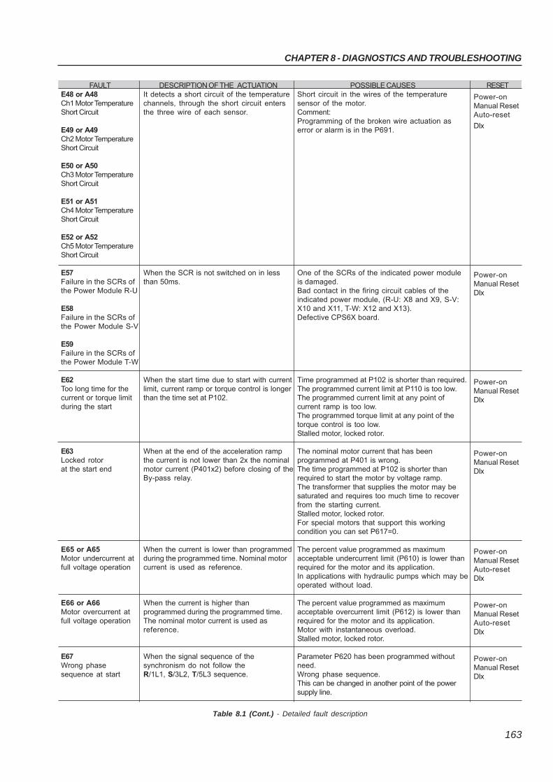
CHAPTER 8 - DIAGNOSTICS AND TROUBLESHOOTING
163
FAULTE48 or A48Ch1 Motor TemperatureShort Circuit
E49 or A49Ch2 Motor TemperatureShort Circuit
E50 or A50Ch3 Motor TemperatureShort Circuit
E51 or A51Ch4 Motor TemperatureShort Circuit
E52 or A52Ch5 Motor TemperatureShort Circuit
E57Failure in the SCRs ofthe Power Module R-U
E58Failure in the SCRs ofthe Power Module S-V
E59Failure in the SCRs ofthe Power Module T-W
E62Too long time for thecurrent or torque limitduring the start
E63Locked rotorat the start end
E65 or A65Motor undercurrent atfull voltage operation
E66 or A66Motor overcurrent atfull voltage operation
E67Wrong phasesequence at start
DESCRIPTION OF THE ACTUATIONIt detects a short circuit of the temperaturechannels, through the short circuit entersthe three wire of each sensor.
When the SCR is not switched on in lessthan 50ms.
When the start time due to start with currentlimit, current ramp or torque control is longerthan the time set at P102.
When at the end of the acceleration rampthe current is not lower than 2x the nominalmotor current (P401x2) before closing of theBy-pass relay.
When the current is lower than programmedduring the programmed time. Nominal motorcurrent is used as reference.
When the current is higher thanprogrammed during the programmed time.The nominal motor current is used asreference.
When the signal sequence of thesynchronism do not follow theR/1L1, S/3L2, T/5L3 sequence.
POSSIBLE CAUSESShort circuit in the wires of the temperaturesensor of the motor.Comment:Programming of the broken wire actuation aserror or alarm is in the P691.
One of the SCRs of the indicated power moduleis damaged.Bad contact in the firing circuit cables of theindicated power module, (R-U: X8 and X9, S-V:X10 and X11, T-W: X12 and X13).Defective CPS6X board.
Time programmed at P102 is shorter than required.The programmed current limit at P110 is too low.The programmed current limit at any point ofcurrent ramp is too low.The programmed torque limit at any point of thetorque control is too low.Stalled motor, locked rotor.
The nominal motor current that has beenprogrammed at P401 is wrong.The time programmed at P102 is shorter thanrequired to start the motor by voltage ramp.The transformer that supplies the motor may besaturated and requires too much time to recoverfrom the starting current.Stalled motor, locked rotor.For special motors that support this workingcondition you can set P617=0.
The percent value programmed as maximumacceptable undercurrent limit (P610) is lower thanrequired for the motor and its application.In applications with hydraulic pumps which may beoperated without load.
The percent value programmed as maximumacceptable overcurrent limit (P612) is lower thanrequired for the motor and its application.Motor with instantaneous overload.Stalled motor, locked rotor.
Parameter P620 has been programmed withoutneed.Wrong phase sequence.This can be changed in another point of the powersupply line.
RESET
Power-onManual ResetAuto-reset
DIx
Power-onManual ResetDIx
Power-onManual ResetDIx
Power-onManual ResetDIx
Power-onManual ResetAuto-resetDIx
Power-onManual ResetAuto-resetDIx
Power-onManual ResetDIx
Table 8.1 (Cont.) - Detailed fault description
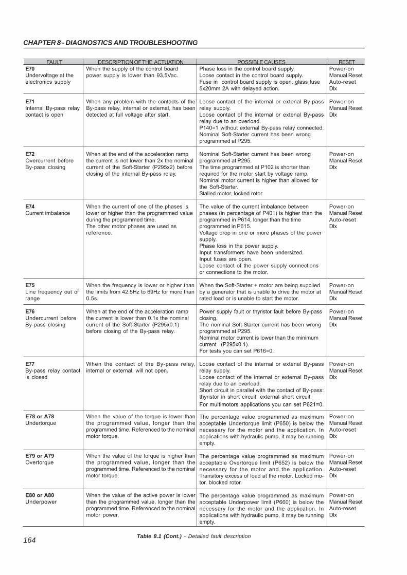
CHAPTER 8 - DIAGNOSTICS AND TROUBLESHOOTING
164
FAULTE70Undervoltage at theelectronics supply
E71Internal By-pass relaycontact is open
E72Overcurrent beforeBy-pass closing
E74Current imbalance
E75Line frequency out ofrange
E76Undercurrent beforeBy-pass closing
E77By-pass relay contactis closed
E78 or A78Undertorque
E79 or A79Overtorque
E80 or A80Underpower
DESCRIPTION OF THE ACTUATIONWhen the supply of the control boardpower supply is lower than 93,5Vac.
When any problem with the contacts of theBy-pass relay, internal or external, has beendetected at full voltage after start.
When at the end of the acceleration rampthe current is not lower than 2x the nominalcurrent of the Soft-Starter (P295x2) beforeclosing of the internal By-pass relay.
When the current of one of the phases islower or higher than the programmed valueduring the programmed time.The other motor phases are used asreference.
When the frequency is lower or higher thanthe limits from 42.5Hz to 69Hz for more than0.5s.
When at the end of the acceleration rampthe current is lower than 0.1x the nominalcurrent of the Soft-Starter (P295x0.1)before closing of the By-pass relay.
When the contact of the By-pass relay,internal or external, will not open.
When the value of the torque is lower thanthe programmed value, longer than theprogrammed time. Referenced to the nominalmotor torque.
When the value of the torque is higher thanthe programmed value, longer than theprogrammed time. Referenced to the nominalmotor torque.
When the value of the active power is lowerthan the programmed value, longer than theprogrammed time. Referenced to the nominalmotor power.
POSSIBLE CAUSESPhase loss in the control board supply.Loose contact in the control board supply.Fuse in control board supply is open, glass fuse5x20mm 2A with delayed action.
Loose contact of the internal or extenal By-passrelay supply.Loose contact of the internal or extenal By-passrelay due to an overload.P140=1 without external By-pass relay connected.Nominal Soft-Starter current has been wrongprogrammed at P295.
Nominal Soft-Starter current has been wrongprogrammed at P295.The time programmed at P102 is shorter thanrequired for the motor start by voltage ramp.Nominal motor current is higher than allowed forthe Soft-Starter.Stalled motor, locked rotor.
The value of the current imbalance betweenphases (in percentage of P401) is higher than theprogrammed in P614, longer than the timeprogrammed in P615.Voltage drop in one or more phases of the powersupply.Phase loss in the power supply.Input transformers have been undersized.Input fuses are open.Loose contact of the power supply connectionsor connections to the motor.
When the Soft-Starter + motor are being suppliedby a generator that is unable to drive the motor atrated load or is unable to start the motor.
Power supply fault or thyristor fault before By-passclosing.The nominal Soft-Starter current has been wrongprogrammed at P295.Nominal motor current is lower than the minimumcurrent (P295x0.1).For tests you can set P616=0.
Loose contact of the internal or extenal By-passrelay supply.Loose contact of the internal or external By-passrelay due to an overload.Short circuit in parallel with the contact of By-pass:thyristor in short circuit, external short circuit.
For multimotors applications you can set P621=0.
The percentage value programmed as maximumacceptable Undertorque limit (P650) is below thenecessary for the motor and the application. Inapplications with hydraulic pump, it may be runningempty.
The percentage value programmed as maximumacceptable Overtorque limit (P652) is below thenecessary for the motor and the application.Transitory excess of load at the motor. Locked mo-tor, blocked rotor.
The percentage value programmed as maximumacceptable Underpower limit (P660) is below thenecessary for the motor and the application. Inapplications with hydraulic pump, it may be runningempty.
RESETPower-onManual ResetAuto-resetDIx
Power-onManual ResetDIx
Power-onManual ResetDIx
Power-onManual ResetAuto-resetDIx
Power-onManual ResetDIx
Power-onManual ResetDIx
Power-onManual ResetDIx
Power-onManual ResetAuto-resetDIx
Power-onManual ResetAuto-resetDIx
Power-onManual ResetAuto-resetDIx
Table 8.1 (Cont.) - Detailed fault description
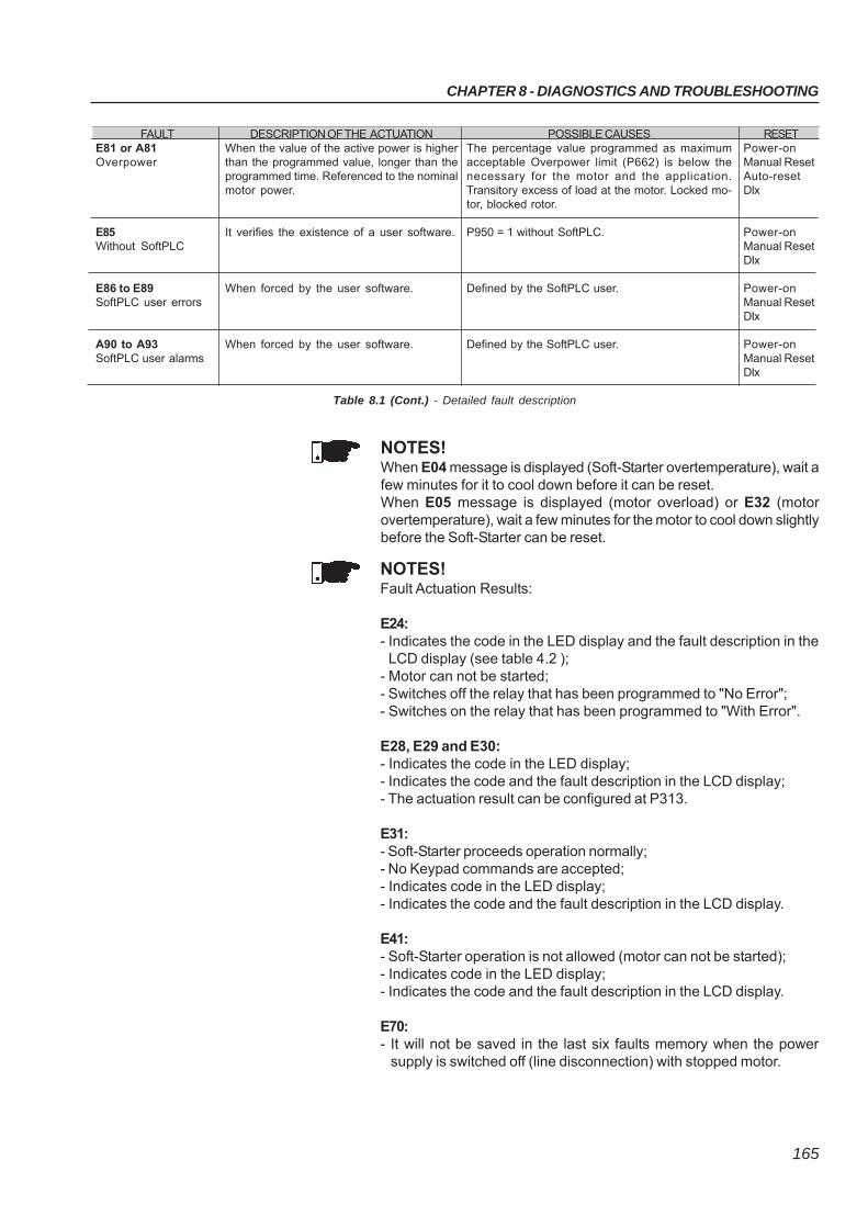
CHAPTER 8 - DIAGNOSTICS AND TROUBLESHOOTING
165
NOTES!Fault Actuation Results:
E24:- Indicates the code in the LED display and the fault description in the
LCD display (see table 4.2 );- Motor can not be started;- Switches off the relay that has been programmed to "No Error";- Switches on the relay that has been programmed to "With Error".
E28, E29 and E30:- Indicates the code in the LED display;- Indicates the code and the fault description in the LCD display;- The actuation result can be configured at P313.
E31:- Soft-Starter proceeds operation normally;- No Keypad commands are accepted;- Indicates code in the LED display;- Indicates the code and the fault description in the LCD display.
E41:- Soft-Starter operation is not allowed (motor can not be started);- Indicates code in the LED display;- Indicates the code and the fault description in the LCD display.
E70:- It will not be saved in the last six faults memory when the power
supply is switched off (line disconnection) with stopped motor.
NOTES!When E04 message is displayed (Soft-Starter overtemperature), wait afew minutes for it to cool down before it can be reset.When E05 message is displayed (motor overload) or E32 (motorovertemperature), wait a few minutes for the motor to cool down slightlybefore the Soft-Starter can be reset.
FAULTE81 or A81Overpower
E85Without SoftPLC
E86 to E89SoftPLC user errors
A90 to A93SoftPLC user alarms
DESCRIPTION OF THE ACTUATIONWhen the value of the active power is higherthan the programmed value, longer than theprogrammed time. Referenced to the nominalmotor power.
It verifies the existence of a user software.
When forced by the user software.
When forced by the user software.
POSSIBLE CAUSESThe percentage value programmed as maximumacceptable Overpower limit (P662) is below thenecessary for the motor and the application.Transitory excess of load at the motor. Locked mo-tor, blocked rotor.
P950 = 1 without SoftPLC.
Defined by the SoftPLC user.
Defined by the SoftPLC user.
RESETPower-onManual ResetAuto-resetDIx
Power-onManual ResetDIx
Power-onManual ResetDIx
Power-onManual ResetDIx
Table 8.1 (Cont.) - Detailed fault description
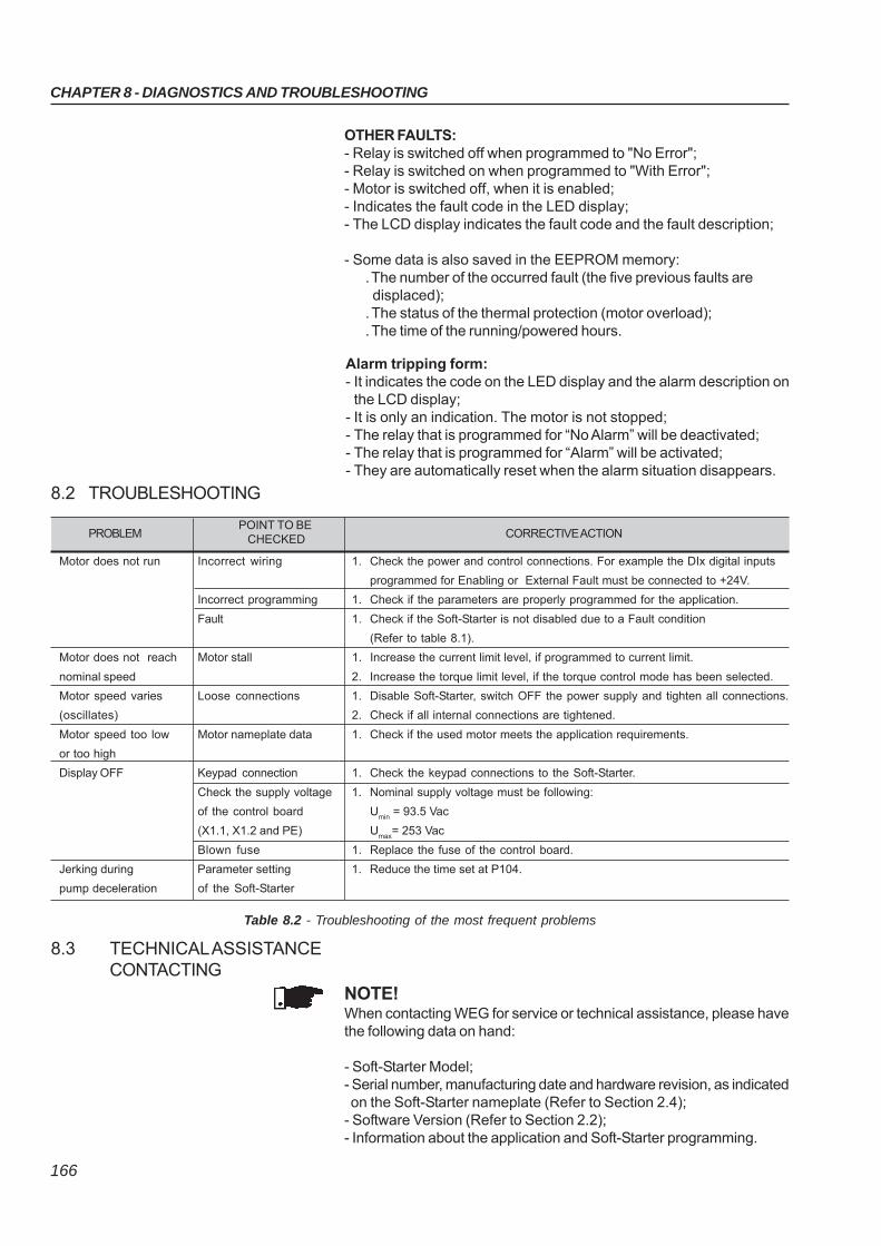
CHAPTER 8 - DIAGNOSTICS AND TROUBLESHOOTING
166
8.2 TROUBLESHOOTING
PROBLEM POINT TO BE
CORRECTIVE ACTION CHECKED
Motor does not run Incorrect wiring 1. Check the power and control connections. For example the DIx digital inputs
programmed for Enabling or External Fault must be connected to +24V.
Incorrect programming 1. Check if the parameters are properly programmed for the application.
Fault 1. Check if the Soft-Starter is not disabled due to a Fault condition
(Refer to table 8.1).
Motor does not reach Motor stall 1. Increase the current limit level, if programmed to current limit.
nominal speed 2. Increase the torque limit level, if the torque control mode has been selected.
Motor speed varies Loose connections 1. Disable Soft-Starter, switch OFF the power supply and tighten all connections.
(oscillates) 2. Check if all internal connections are tightened.
Motor speed too low Motor nameplate data 1. Check if the used motor meets the application requirements.
or too high
Display OFF Keypad connection 1. Check the keypad connections to the Soft-Starter.
Check the supply voltage 1. Nominal supply voltage must be following:
of the control board Umin
= 93.5 Vac
(X1.1, X1.2 and PE) Umax
= 253 Vac
Blown fuse 1. Replace the fuse of the control board.
Jerking during Parameter setting 1. Reduce the time set at P104.
pump deceleration of the Soft-Starter
Table 8.2 - Troubleshooting of the most frequent problems
NOTE!When contacting WEG for service or technical assistance, please havethe following data on hand:
- Soft-Starter Model;- Serial number, manufacturing date and hardware revision, as indicated on the Soft-Starter nameplate (Refer to Section 2.4);- Software Version (Refer to Section 2.2);- Information about the application and Soft-Starter programming.
8.3 TECHNICAL ASSISTANCECONTACTING
Alarm tripping form:- It indicates the code on the LED display and the alarm description on
the LCD display;- It is only an indication. The motor is not stopped;- The relay that is programmed for “No Alarm” will be deactivated;- The relay that is programmed for “Alarm” will be activated;- They are automatically reset when the alarm situation disappears.
OTHER FAULTS:- Relay is switched off when programmed to "No Error";- Relay is switched on when programmed to "With Error";- Motor is switched off, when it is enabled;- Indicates the fault code in the LED display;- The LCD display indicates the fault code and the fault description;
- Some data is also saved in the EEPROM memory:. The number of the occurred fault (the five previous faults are displaced);. The status of the thermal protection (motor overload);. The time of the running/powered hours.
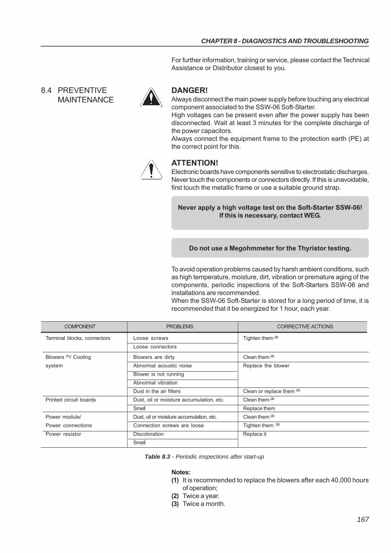
CHAPTER 8 - DIAGNOSTICS AND TROUBLESHOOTING
167
8.4 PREVENTIVEMAINTENANCE
DANGER!Always disconnect the main power supply before touching any electricalcomponent associated to the SSW-06 Soft-Starter.High voltages can be present even after the power supply has beendisconnected. Wait at least 3 minutes for the complete discharge ofthe power capacitors.Always connect the equipment frame to the protection earth (PE) atthe correct point for this.
ATTENTION!Electronic boards have components sensitive to electrostatic discharges.Never touch the components or connectors directly. If this is unavoidable,first touch the metallic frame or use a suitable ground strap.
To avoid operation problems caused by harsh ambient conditions, suchas high temperature, moisture, dirt, vibration or premature aging of thecomponents, periodic inspections of the Soft-Starters SSW-06 andinstallations are recommended.When the SSW-06 Soft-Starter is stored for a long period of time, it isrecommended that it be energized for 1 hour, each year.
Never apply a high voltage test on the Soft-Starter SSW-06!If this is necessary, contact WEG.
COMPONENT PROBLEMS CORRECTIVE ACTIONS
Terminal blocks, connectors Loose screws Tighten them (2)
Loose connectors
Blowers (1)/ Cooling Blowers are dirty Clean them (2)
system Abnormal acoustic noise Replace the blower
Blower is not running
Abnormal vibration
Dust in the air filters Clean or replace them (3)
Printed circuit boards Dust, oil or moisture accumulation, etc. Clean them (2)
Smell Replace them
Power module/ Dust, oil or moisture accumulation, etc. Clean them (2)
Power connections Connection screws are loose Tighten them (2)
Power resistor Discoloration Replace it
Smell
Table 8.3 - Periodic inspections after start-up
Notes:(1) It is recommended to replace the blowers after each 40,000 hours
of operation;(2) Twice a year.(3) Twice a month.
Do not use a Megohmmeter for the Thyristor testing.
For further information, training or service, please contact the TechnicalAssistance or Distributor closest to you.
CHAPTER 8 - DIAGNOSTICS AND TROUBLESHOOTING
168
When it is necessary to clean the SSW-06 Soft-Starter, do so accordingto the following instructions:
a) Cooling system:
Remove AC power from the Soft-Starter SSW-06 and wait 3 minutes;Remove all dust from the ventilation openings by using a plasticbrush or a soft cloth;Remove dust accumulated on the heat sink fins and from the blowerblades with compressed air.
b) Electronic boards:
Remove AC power from the Soft-Starter SSW-06 and wait 3 minutes;Remove all dust from the printed circuit boards by using an anti-static soft brush or remove it with an ionized compressed air gun(example Charges Burtes Ion Gun (non nuclear) - referenceA6030-6DESCO);If necessary, remove the PCBs from the Soft-Starter SSW-06;Always use a ground strap.
8.4.1 Cleaning Instructions
CHAPTER 8 - DIAGNOSTICS AND TROUBLESHOOTING
169
8.5 SPARE PART LIST
Table 8.4 - Spare parts list
* a) The 110Vac fan is used in the SSW06XXXXT2257ESH1Z.b) The 220Vac fan is used in the SSW06XXXXT2257ESH2Z.
CHAPTER 8 - DIAGNOSTICS AND TROUBLESHOOTING
170
Table 8.5 - Spare parts list line 575-690Vac
* a) The 110Vac fan is used in the SSW06xxxxT5769ESH1Zb) The 220Vac fan is used in the SSW06xxxxT5769ESH2Z
171
CHAPTER 9
9.1 REMOTE KEYPAD AND CABLES
OPTIONS AND ACCESSORIES
This chapter describes the options and accessories that can be usedwith the Soft-Starter SSW-06. These options and accessories are:Remote keypad and cables.
The keypad can be assembled either on the Soft-Starter or remotely. Ifusing the remote keypad, the frame KMR-SSW-06 (frame for remotemounting) can be used. The advantage of using the frame is theappearance (aesthetic) of the remote keypad. The maximum cable lengthis 5m (16.40 ft). To acquire cables from WEG, see the following models.
Cable Length WEG Part No
1m (3.28ft) 10050237
2m (6.56ft) 10050235
3m (9.84ft) 10050234
5m (16.40ft) 10050233
Table 9.1 - Connection cables CAB-HMI SSW-06-X
The keypad cable must be installed separately from the power cables,following the same recommendations as for the CCS6 control board(Refer to Section 3.2.8).For assembling, see details in figure 9.2 and 9.3.
Figure 9.1 - Keypad and remote keypad frame for panel installation
NOTE!Due to voltage drops in the Keypad cable, do not use cables longerthan 5m (16.40ft).
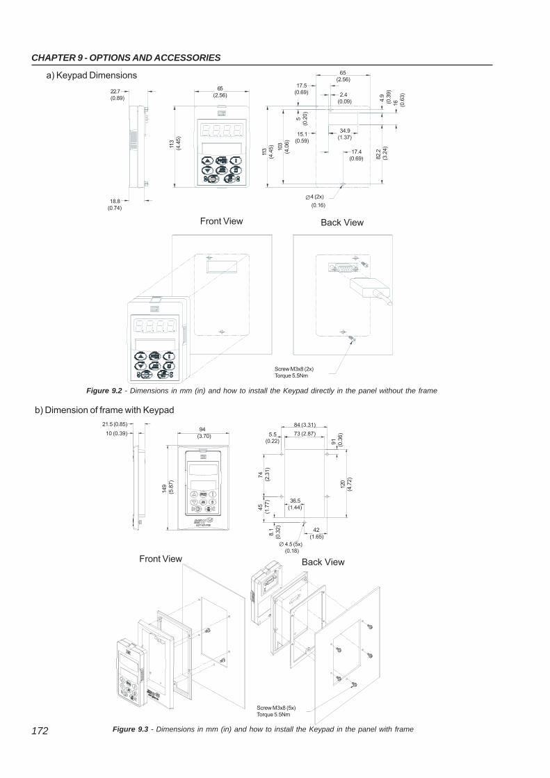
172
CHAPTER 9 - OPTIONS AND ACCESSORIES
Figure 9.3 - Dimensions in mm (in) and how to install the Keypad in the panel with frame
Figure 9.2 - Dimensions in mm (in) and how to install the Keypad directly in the panel without the frame
17.5(0.69)
65(2.56)
17.4(0.69)
4.9
(0.3
9) 1
6(0
.63)
82.
2(3
.24)
34.9(1.37)
15.1(0.59)
2.4(0.09)
103
(4.0
6)
5
(0.2
0)
113
(4.4
5)
4 (2x)∅(0.16)
Screw M3x8 (2x)Torque 5.5Nm
Front View Back View
84 (3.31)
5.5(0.22)
42(1.65)
120
(4.7
2)
36.5(1.44)
91
(0.3
6)
74
(2.3
1)
4.5 (5x)(0.18)
∅
Screw M3x8 (5x)Torque 5.5Nm
b) Dimension of frame with Keypad
Back View
73 (2.87)
45
(1.7
7)
8.1
(0.3
2)
22.7(0.89)
65(2.56)
113
(4.4
5)
18.8(0.74)
a) Keypad Dimensions
21.5 (0.85) 94(3.70)
149
(5.8
7)
Front View
10 (0.39)
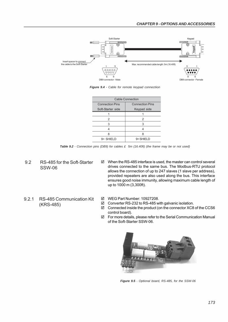
CHAPTER 9 - OPTIONS AND ACCESSORIES
173
Figure 9.4 - Cable for remote keypad connectiion
Table 9.2 - Connection pins (DB9) for cables £ 5m (16.40ft) (the frame may be or not used)
Connection Pins
Keypad side
1
2
3
4
8
9= SHIELD
Cable Connection
Connection Pins
Soft-Starter side
1
2
3
4
8
9= SHIELD
When the RS-485 interface is used, the master can control severaldrives connected to the same bus. The Modbus-RTU protocolallows the connection of up to 247 slaves (1 slave per address),provided repeaters are also used along the bus. This interfaceensures good noise immunity, allowing maximum cable length ofup to 1000 m (3,300ft).
WEG Part Number: 10927208. Converter RS-232 to RS-485 with galvanic isolation. Connected inside the product (on the connector XC8 of the CCS6
control board). For more details, please refer to the Serial Communication Manual
of the Soft-Starter SSW-06.
9.2 RS-485 for the Soft-StarterSSW-06
9.2.1 RS-485 Communication Kit(KRS-485)
Figure 9.5 - Optional board, RS-485, for the SSW-06
Keyp
ad
Sof
t-Sta
rter
DB9 connector - Male
Max. recommended cable length: 5m (16.40ft)
DB9 connector - Female
KeypadSoft-Starter
Insert spacer to connectthe cable to the Soft-Starter
1 5
96
5 1
69
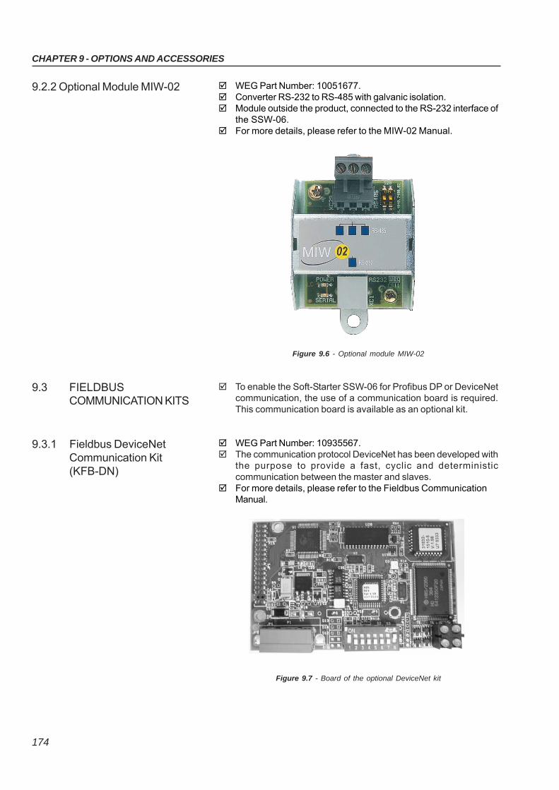
174
CHAPTER 9 - OPTIONS AND ACCESSORIES
WEG Part Number: 10051677. Converter RS-232 to RS-485 with galvanic isolation. Module outside the product, connected to the RS-232 interface of
the SSW-06. For more details, please refer to the MIW-02 Manual.
9.2.2 Optional Module MIW-02
Figure 9.6 - Optional module MIW-02
To enable the Soft-Starter SSW-06 for Profibus DP or DeviceNetcommunication, the use of a communication board is required.This communication board is available as an optional kit.
WEG Part Number: 10935567. The communication protocol DeviceNet has been developed with
the purpose to provide a fast, cyclic and deterministiccommunication between the master and slaves.
For more details, please refer to the Fieldbus CommunicationManual.
9.3 FIELDBUSCOMMUNICATION KITS
9.3.1 Fieldbus DeviceNetCommunication Kit(KFB-DN)
Figure 9.7 - Board of the optional DeviceNet kit
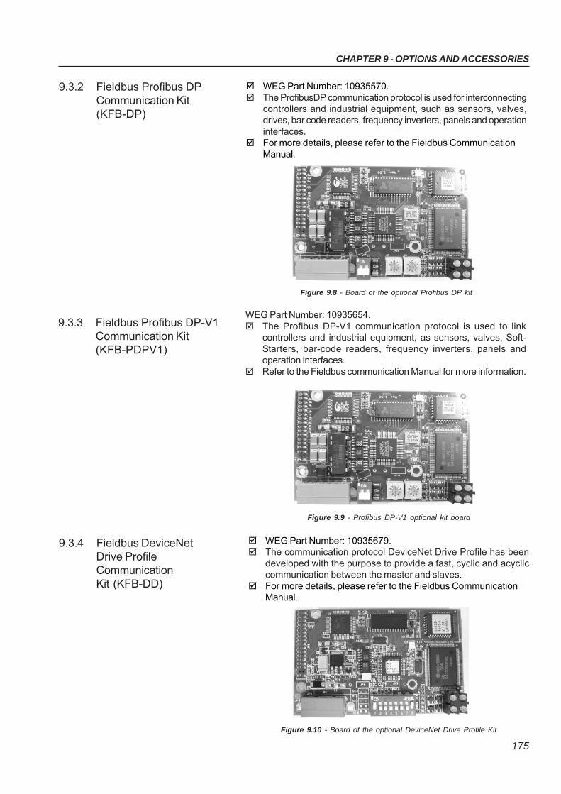
CHAPTER 9 - OPTIONS AND ACCESSORIES
175
WEG Part Number: 10935570. The ProfibusDP communication protocol is used for interconnecting
controllers and industrial equipment, such as sensors, valves,drives, bar code readers, frequency inverters, panels and operationinterfaces.
For more details, please refer to the Fieldbus CommunicationManual.
9.3.2 Fieldbus Profibus DPCommunication Kit(KFB-DP)
Figure 9.8 - Board of the optional Profibus DP kit
WEG Part Number: 10935654. The Profibus DP-V1 communication protocol is used to link
controllers and industrial equipment, as sensors, valves, Soft-Starters, bar-code readers, frequency inverters, panels andoperation interfaces.
Refer to the Fieldbus communication Manual for more information.
9.3.3 Fieldbus Profibus DP-V1Communication Kit(KFB-PDPV1)
Figure 9.9 - Profibus DP-V1 optional kit board
9.3.4 Fieldbus DeviceNetDrive ProfileCommunicationKit (KFB-DD)
WEG Part Number: 10935679. The communication protocol DeviceNet Drive Profile has been
developed with the purpose to provide a fast, cyclic and acycliccommunication between the master and slaves.
For more details, please refer to the Fieldbus CommunicationManual.
Figure 9.10 - Board of the optional DeviceNet Drive Profile Kit
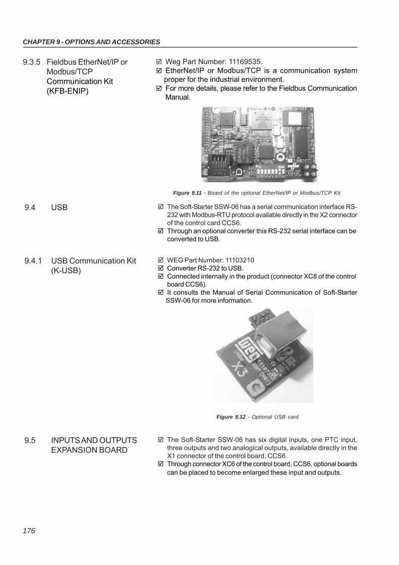
176
CHAPTER 9 - OPTIONS AND ACCESSORIES
Weg Part Number: 11169535. EtherNet/IP or Modbus/TCP is a communication system
proper for the industrial environment. For more details, please refer to the Fieldbus Communication
Manual.
9.3.5 Fieldbus EtherNet/IP orModbus/TCPCommunication Kit(KFB-ENIP)
Figure 9.11 - Board of the optional EtherNet/IP or Modbus/TCP Kit
The Soft-Starter SSW-06 has a serial communication interface RS-232 with Modbus-RTU protocol available directly in the X2 connectorof the control card CCS6.
Through an optional converter this RS-232 serial interface can beconverted to USB.
9.4 USB
WEG Part Number: 11103210 Converter RS-232 to USB. Connected internally in the product (connector XC8 of the control
board CCS6). It consults the Manual of Serial Communication of Soft-Starter
SSW-06 for more information.
9.4.1 USB Communication Kit(K-USB)
Figure 9.12 - Optional USB card
The Soft-Starter SSW-06 has six digital inputs, one PTC input,three outputs and two analogical outputs, available directly in theX1 connector of the control board, CCS6.
Through connector XC6 of the control board, CCS6, optional boardscan be placed to become enlarged these input and outputs.
9.5 INPUTS AND OUTPUTSEXPANSION BOARD
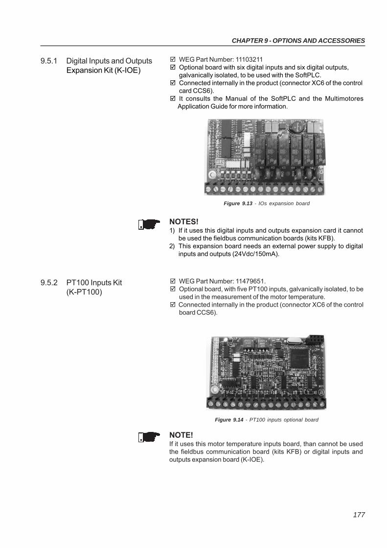
CHAPTER 9 - OPTIONS AND ACCESSORIES
177
9.5.1 Digital Inputs and OutputsExpansion Kit (K-IOE)
WEG Part Number: 11103211 Optional board with six digital inputs and six digital outputs,
galvanically isolated, to be used with the SoftPLC. Connected internally in the product (connector XC6 of the control
card CCS6). It consults the Manual of the SoftPLC and the Multimotores
Application Guide for more information.
Figure 9.13 - IOs expansion board
NOTES!1) If it uses this digital inputs and outputs expansion card it cannot
be used the fieldbus communication boards (kits KFB).2) This expansion board needs an external power supply to digital
inputs and outputs (24Vdc/150mA).
9.5.2 PT100 Inputs Kit(K-PT100)
WEG Part Number: 11479651. Optional board, with five PT100 inputs, galvanically isolated, to be
used in the measurement of the motor temperature. Connected internally in the product (connector XC6 of the control
board CCS6).
Figure 9.14 - PT100 inputs optional board
NOTE!If it uses this motor temperature inputs board, than cannot be usedthe fieldbus communication board (kits KFB) or digital inputs andoutputs expansion board (K-IOE).
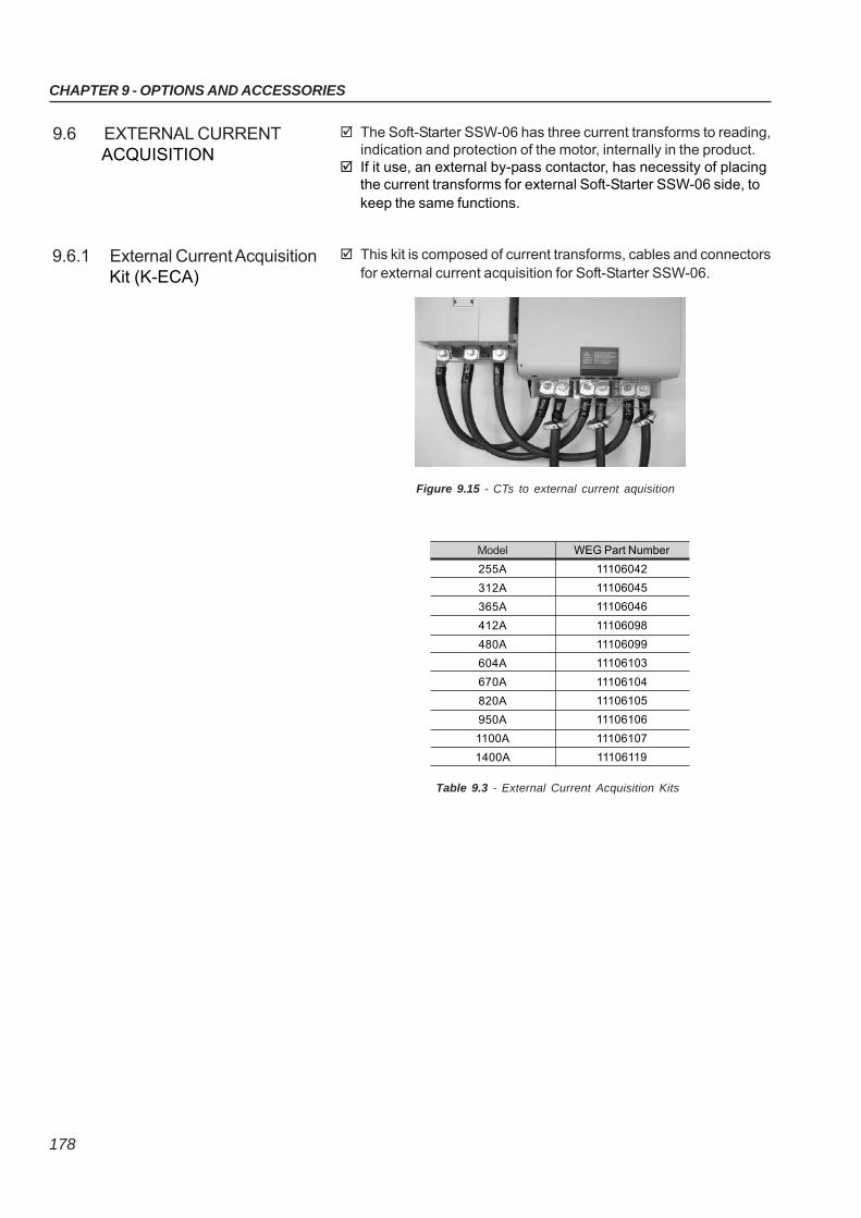
178
CHAPTER 9 - OPTIONS AND ACCESSORIES
WEG Part Number
11106042
11106045
11106046
11106098
11106099
11106103
11106104
11106105
11106106
11106107
11106119
Model
255A
312A
365A
412A
480A
604A
670A
820A
950A
1100A
1400A
Table 9.3 - External Current Acquisition Kits
9.6.1 External Current Acquisition Kit (K-ECA)
This kit is composed of current transforms, cables and connectorsfor external current acquisition for Soft-Starter SSW-06.
Figure 9.15 - CTs to external current aquisition
The Soft-Starter SSW-06 has three current transforms to reading,indication and protection of the motor, internally in the product.
If it use, an external by-pass contactor, has necessity of placingthe current transforms for external Soft-Starter SSW-06 side, tokeep the same functions.
9.6 EXTERNAL CURRENT ACQUISITION
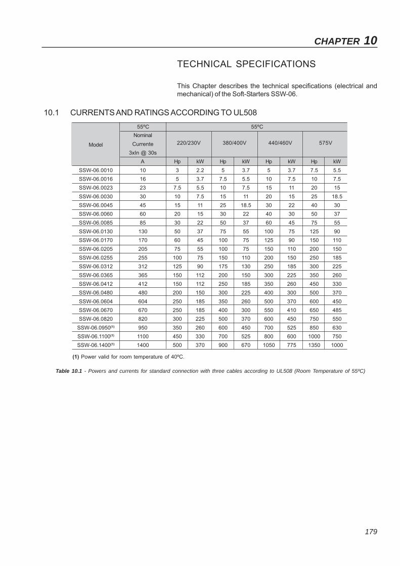
179
CHAPTER 10
TECHNICAL SPECIFICATIONS
This Chapter describes the technical specifications (electrical andmechanical) of the Soft-Starters SSW-06.
10.1 CURRENTS AND RATINGS ACCORDING TO UL508
Table 10.1 - Powers and currents for standard connection with three cables according to UL508 (Room Temperature of 55ºC)
Model
SSW-06.0010
SSW-06.0016
SSW-06.0023
SSW-06.0030
SSW-06.0045
SSW-06.0060
SSW-06.0085
SSW-06.0130
SSW-06.0170
SSW-06.0205
SSW-06.0255
SSW-06.0312
SSW-06.0365
SSW-06.0412
SSW-06.0480
SSW-06.0604
SSW-06.0670
SSW-06.0820
SSW-06.0950(1)
SSW-06.1100(1)
SSW-06.1400(1)
Nominal
Currente
3xIn @ 30s
A
10
16
23
30
45
60
85
130
170
205
255
312
365
412
480
604
670
820
950
1100
1400
220/230V
Hp kW
3 2.2
5 3.7
7.5 5.5
10 7.5
15 11
20 15
30 22
50 37
60 45
75 55
100 75
125 90
150 112
150 112
200 150
250 185
250 185
300 225
350 260
450 330
500 370
380/400V
Hp kW
5 3.7
7.5 5.5
10 7.5
15 11
25 18.5
30 22
50 37
75 55
100 75
100 75
150 110
175 130
200 150
250 185
300 225
350 260
400 300
500 370
600 450
700 525
900 670
440/460V
Hp kW
5 3.7
10 7.5
15 11
20 15
30 22
40 30
60 45
100 75
125 90
150 110
200 150
250 185
300 225
350 260
400 300
500 370
550 410
600 450
700 525
800 600
1050 775
575V
Hp kW
7.5 5.5
10 7.5
20 15
25 18.5
40 30
50 37
75 55
125 90
150 110
200 150
250 185
300 225
350 260
450 330
500 370
600 450
650 485
750 550
850 630
1000 750
1350 1000
55ºC 55ºC
(1) Power valid for room temperature of 40ºC.
CHAPTER 10 - TECHNICAL SPECIFICATIONS
180
Table 10.2 - Powers and currents for inside delta motor connection with six cables according to UL508(Room Temperature of 55ºC)
NOTE!Maximum ratings indicated in tables 10.1 and 10.3 are based on 3 xSSW-06 Soft-Starter Nominal Current during 30s and 10 starts perhour (3xIn@30s) from 10A to 820A models and 5 starts per hour (3xIn@30s) from 950A to 1400A models.
(1) Power valid for room temperature of 40ºC.
Model
SSW-06.0010
SSW-06.0016
SSW-06.0023
SSW-06.0030
SSW-06.0045
SSW-06.0060
SSW-06.0085
SSW-06.0130
SSW-06.0170
SSW-06.0205
SSW-06.0255
SSW-06.0312
SSW-06.0365
SSW-06.0412
SSW-06.0480
SSW-06.0604
SSW-06.0670
SSW-06.0820
SSW-06.0950(1)
SSW-06.1100(1)
SSW-06.1400(1)
Nominal
Current
3xIn @ 25s
A
-
-
-
-
77
103
147
225
294
355
441
540
631
713
831
1046
1160
1420
1645
1905
2424
220/230V
Hp kW
- -
- -
- -
- -
25 18.5
30 22
50 37
75 55
100 75
125 90
150 110
200 150
250 185
250 185
350 260
450 330
450 330
550 410
650 485
800 600
1000 750
380/400V
Hp kW
- -
- -
- -
- -
40 30
60 45
75 55
125 90
150 110
200 150
250 185
300 225
350 260
450 330
550 410
700 525
850 630
1000 750
1150 820
1350 1000
1750 1290
440/460V
Hp kW
- -
- -
- -
- -
60 45
75 55
100 75
150 110
200 150
250 185
350 260
450 330
500 370
550 410
650 485
800 600
900 670
1150 820
1350 1000
1600 1175
2000 1475
575V
Hp kW
- -
- -
- -
- -
75 55
100 75
150 110
200 150
300 225
350 260
450 330
550 410
650 485
750 550
850 630
1100 800
1200 900
1500 1200
1750 1290
2000 1475
2500 1850
55ºC 55ºC
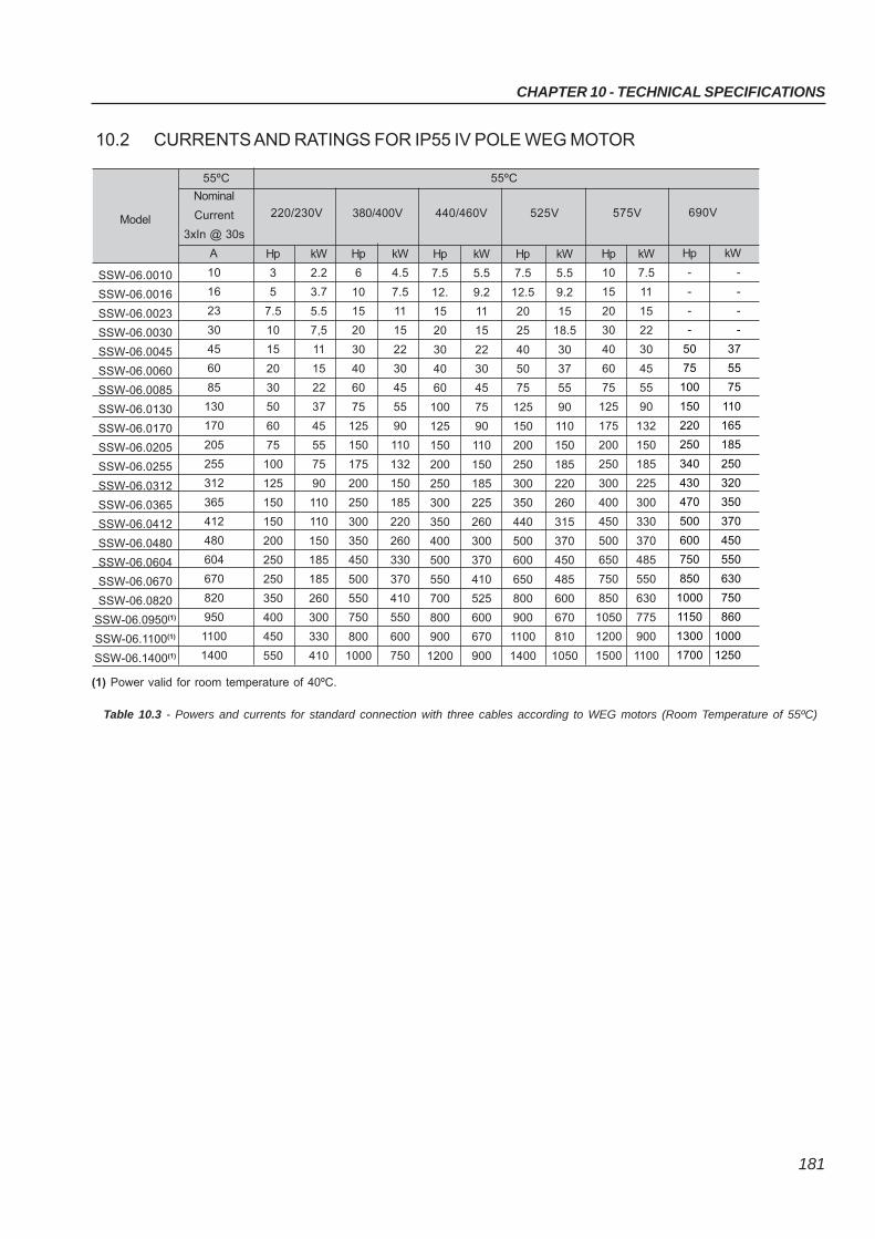
CHAPTER 10 - TECHNICAL SPECIFICATIONS
181
10.2 CURRENTS AND RATINGS FOR IP55 IV POLE WEG MOTOR
Table 10.3 - Powers and currents for standard connection with three cables according to WEG motors (Room Temperature of 55ºC)
(1) Power valid for room temperature of 40ºC.
Model
SSW-06.0010
SSW-06.0016
SSW-06.0023
SSW-06.0030
SSW-06.0045
SSW-06.0060
SSW-06.0085
SSW-06.0130
SSW-06.0170
SSW-06.0205
SSW-06.0255
SSW-06.0312
SSW-06.0365
SSW-06.0412
SSW-06.0480
SSW-06.0604
SSW-06.0670
SSW-06.0820
SSW-06.0950(1)
SSW-06.1100(1)
SSW-06.1400(1)
Nominal
Current
3xIn @ 30s
A
10
16
23
30
45
60
85
130
170
205
255
312
365
412
480
604
670
820
950
1100
1400
220/230V
Hp kW
3 2.2
5 3.7
7.5 5.5
10 7,5
15 11
20 15
30 22
50 37
60 45
75 55
100 75
125 90
150 110
150 110
200 150
250 185
250 185
350 260
400 300
450 330
550 410
380/400V
Hp kW
6 4.5
10 7.5
15 11
20 15
30 22
40 30
60 45
75 55
125 90
150 110
175 132
200 150
250 185
300 220
350 260
450 330
500 370
550 410
750 550
800 600
1000 750
440/460V
Hp kW
7.5 5.5
12. 9.2
15 11
20 15
30 22
40 30
60 45
100 75
125 90
150 110
200 150
250 185
300 225
350 260
400 300
500 370
550 410
700 525
800 600
900 670
1200 900
525V
Hp kW
7.5 5.5
12.5 9.2
20 15
25 18.5
40 30
50 37
75 55
125 90
150 110
200 150
250 185
300 220
350 260
440 315
500 370
600 450
650 485
800 600
900 670
1100 810
1400 1050
55ºC 55ºC
575V
Hp kW
10 7.5
15 11
20 15
30 22
40 30
60 45
75 55
125 90
175 132
200 150
250 185
300 225
400 300
450 330
500 370
650 485
750 550
850 630
1050 775
1200 900
1500 1100
690V
Hp kW
- -
- -
- -
- -
50 37
75 55
100 75
150 110
220 165
250 185
340 250
430 320
470 350
500 370
600 450
750 550
850 630
1000 750
1150 860
1300 1000
1700 1250
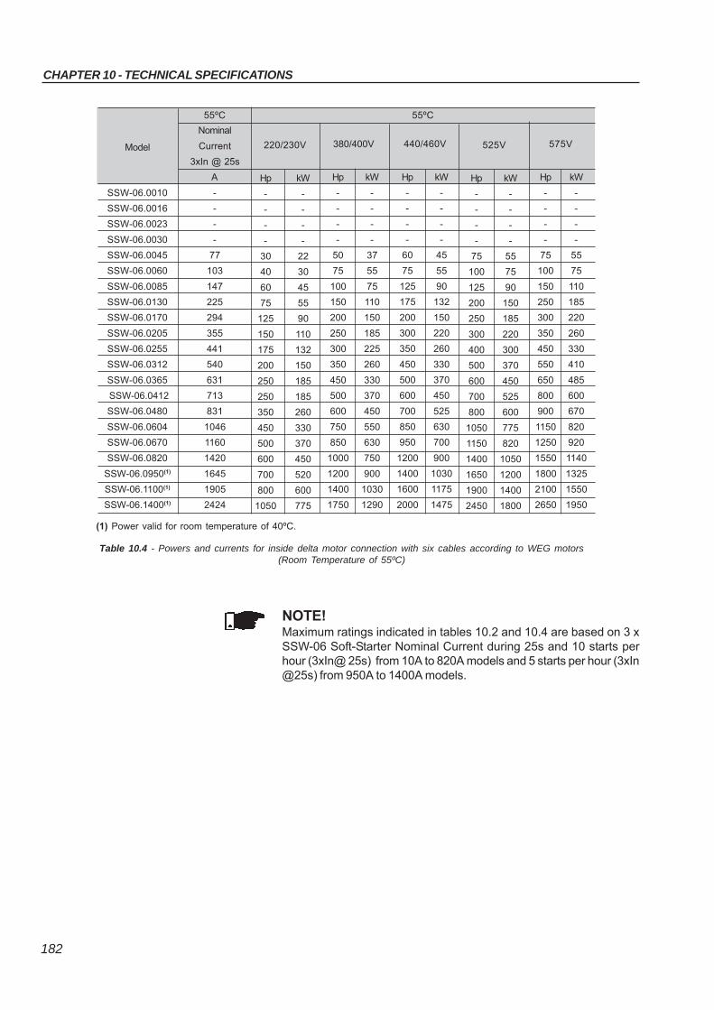
CHAPTER 10 - TECHNICAL SPECIFICATIONS
182
Table 10.4 - Powers and currents for inside delta motor connection with six cables according to WEG motors(Room Temperature of 55ºC)
NOTE!Maximum ratings indicated in tables 10.2 and 10.4 are based on 3 xSSW-06 Soft-Starter Nominal Current during 25s and 10 starts perhour (3xIn@ 25s) from 10A to 820A models and 5 starts per hour (3xIn@25s) from 950A to 1400A models.
Model
SSW-06.0010
SSW-06.0016
SSW-06.0023
SSW-06.0030
SSW-06.0045
SSW-06.0060
SSW-06.0085
SSW-06.0130
SSW-06.0170
SSW-06.0205
SSW-06.0255
SSW-06.0312
SSW-06.0365
SSW-06.0412
SSW-06.0480
SSW-06.0604
SSW-06.0670
SSW-06.0820
SSW-06.0950(1)
SSW-06.1100(1)
SSW-06.1400(1)
Nominal
Current
3xIn @ 25s
A
-
-
-
-
77
103
147
225
294
355
441
540
631
713
831
1046
1160
1420
1645
1905
2424
220/230V
Hp kW
- -
- -
- -
- -
30 22
40 30
60 45
75 55
125 90
150 110
175 132
200 150
250 185
250 185
350 260
450 330
500 370
600 450
700 520
800 600
1050 775
380/400V
Hp kW
- -
- -
- -
- -
50 37
75 55
100 75
150 110
200 150
250 185
300 225
350 260
450 330
500 370
600 450
750 550
850 630
1000 750
1200 900
1400 1030
1750 1290
440/460V
Hp kW
- -
- -
- -
- -
60 45
75 55
125 90
175 132
200 150
300 220
350 260
450 330
500 370
600 450
700 525
850 630
950 700
1200 900
1400 1030
1600 1175
2000 1475
525V
Hp kW
- -
- -
- -
- -
75 55
100 75
125 90
200 150
250 185
300 220
400 300
500 370
600 450
700 525
800 600
1050 775
1150 820
1400 1050
1650 1200
1900 1400
2450 1800
55ºC 55ºC
575V
Hp kW
- -
- -
- -
- -
75 55
100 75
150 110
250 185
300 220
350 260
450 330
550 410
650 485
800 600
900 670
1150 820
1250 920
1550 1140
1800 1325
2100 1550
2650 1950
(1) Power valid for room temperature of 40ºC.
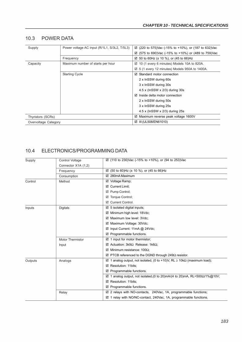
CHAPTER 10 - TECHNICAL SPECIFICATIONS
183
10.3 POWER DATA
Supply
Capacity
Power voltage AC input (R/1L1, S/3L2, T/5L3)
Frequency
Maximum number of starts per hour
Starting Cycle
(220 to 575)Vac (-15% to +10%), or (187 to 632)Vac
(575 to 690)Vac (-15% to +10%) or (489 to 759)Vac
50 to 60Hz (± 10 %), or (45 to 66)Hz
10 (1 every 6 minutes) Models 10A to 820A.
5 (1 every 12 minutes) Models 950A to 1400A.
Standard motor connection
2 x InSSW during 60s
3 x InSSW during 30s
4.5 x (InSSW x 2/3) during 30s
Inside delta motor connection
2 x InSSW during 50s
3 x InSSW during 25s
4.5 x (InSSW x 2/3) during 25s
Maximum reverse peak voltage 1600V
III (UL508/EN61010)Overvoltage Category
10.4 ELECTRONICS/PROGRAMMING DATA
(110 to 230)Vac (-15% to +10%), or (94 to 253)Vac
(50 to 60)Hz (± 10 %), or (45 to 66)Hz
280mA Maximum
Voltage Ramp;
Current Limit;
Pump Control;
Torque Control;
Current Control.
5 isolated digital inputs;
Minimum high level: 18Vdc;
Maximum low level: 3Vdc;
Maximum Voltage: 30Vdc;
Input Current: 11mA @ 24Vdc;
Programmable functions.
1 input for motor thermistor;
Actuation: 3k9Ω Release: 1k6Ω;
Minimum resistance: 100Ω;
PTCB referenced to the DGND through 249Ω resistor.
1 analog output, not isolated, (0 to +10)V, RL ≥ 10kΩ (maximum load);
Resolution: 11bits;
Programmable functions.
1 analog output, not isolated,(0 to 20)mA/(4 to 20)mA, RL=500Ω/1%@10V;
Resolution: 11bits;
Programmable functions.
2 relays with NO-contacts, 240Vac, 1A, programmable functions;
1 relay with NO/NC-contact, 240Vac, 1A, programmable functions.
Supply Control Voltage
Connector X1A (1,2)
Frequency
Consumption
Control Method
Inputs Digitals
Motor Thermistor
Input
Outputs Analogs
Relay
Thyristors (SCRs)
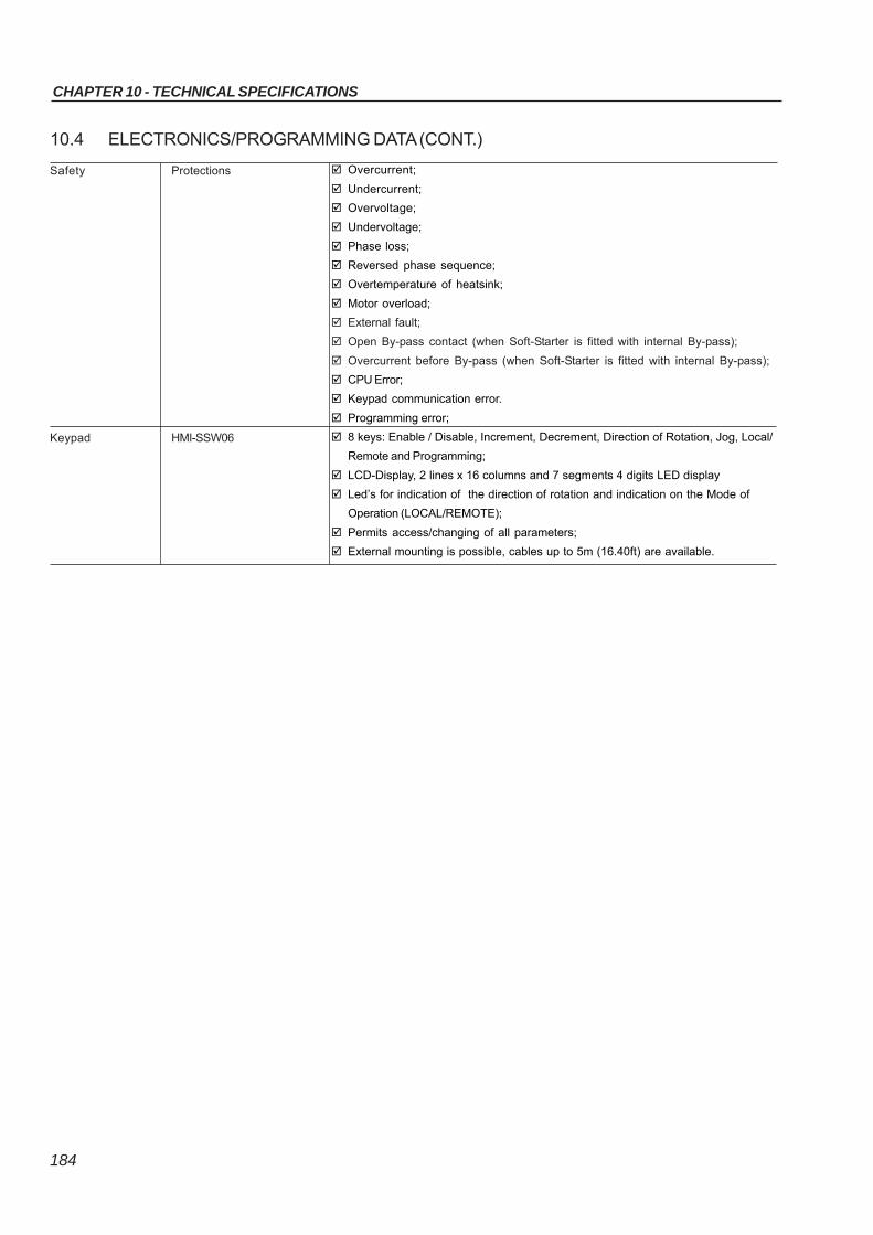
CHAPTER 10 - TECHNICAL SPECIFICATIONS
184
10.4 ELECTRONICS/PROGRAMMING DATA (CONT.)
Overcurrent;
Undercurrent;
Overvoltage;
Undervoltage;
Phase loss;
Reversed phase sequence;
Overtemperature of heatsink;
Motor overload;
External fault;
Open By-pass contact (when Soft-Starter is fitted with internal By-pass);
Overcurrent before By-pass (when Soft-Starter is fitted with internal By-pass);
CPU Error;
Keypad communication error.
Programming error;
8 keys: Enable / Disable, Increment, Decrement, Direction of Rotation, Jog, Local/
Remote and Programming;
LCD-Display, 2 lines x 16 columns and 7 segments 4 digits LED display
Led’s for indication of the direction of rotation and indication on the Mode of
Operation (LOCAL/REMOTE);
Permits access/changing of all parameters;
External mounting is possible, cables up to 5m (16.40ft) are available.
Safety Protections
Keypad HMI-SSW06
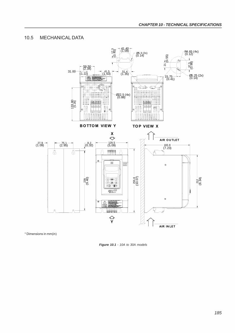
CHAPTER 10 - TECHNICAL SPECIFICATIONS
185
10.5 MECHANICAL DATA
Figure 10.1 - 10A to 30A models
AIR O U TLET
TO P VIEW X
AIR IN LET
(0.5
5)
15.75
21
(0.14)Ø5.25 (2x)
R4.65 (4x)
(0.9
8)37
.5
(0.41)
(0.12)
(0.4
5)17
.3
(0.14)Ø5.3 (2x)
51.4
(1.09)41.40
(1.35)
X
Y
Ø22.5 (4x)(0.88)
B O TTO M VIEW Y
75.127.9 8.2
239
129.5
255.
8
183.8
212
133.
8031.00
59.50
41.5(2.34)
(1.22) (1.63)
(1.09) (2.95) (0,32) (5,09)
(9.4
0)
(10.
0 7)
(7.23)
(8.3
4 )
(5.2
6)
* Dimensions in mm(in)
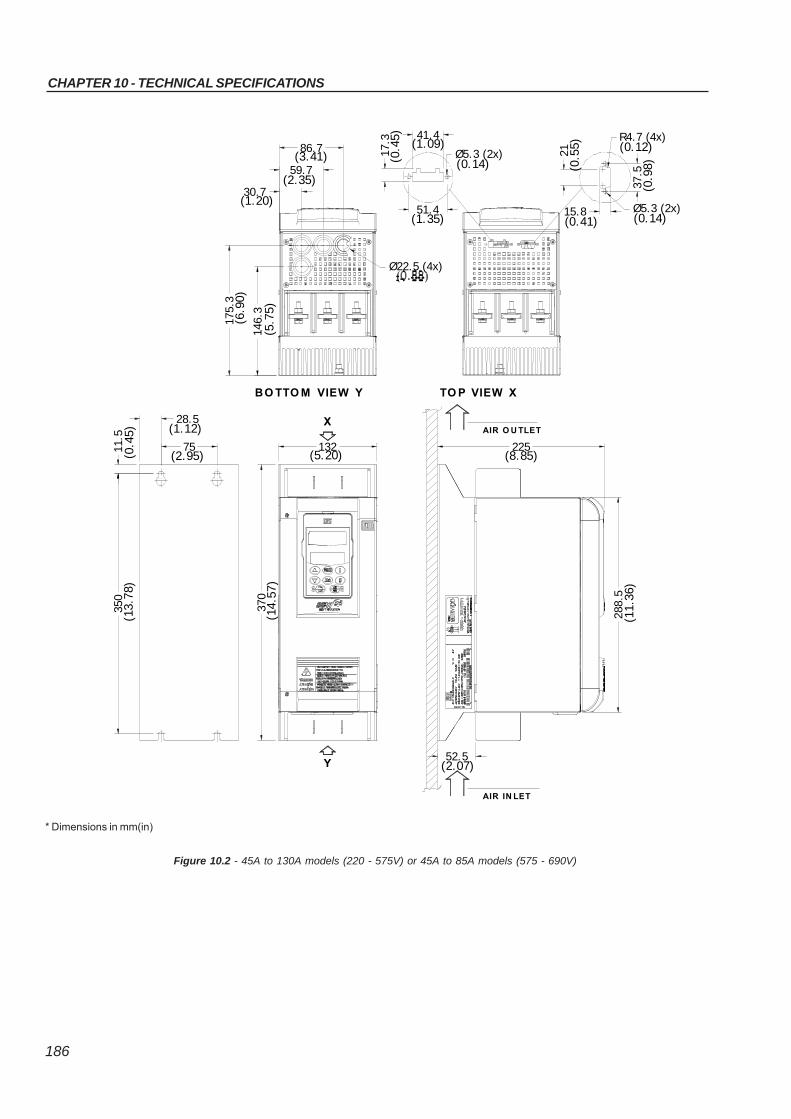
CHAPTER 10 - TECHNICAL SPECIFICATIONS
186
TO P VIEW X
(8.85)225
370
11.5
Y
AIR IN LET
(2.07)52.5
(13.
78)
(14.
57)
( 0.4
5) (1.12)
(2.95)
BO TTO M VIEW Y
132(5.20)
XAIR O U TLET
Ø5.3 (2x)17.3
51.4(1.35)
41.4(1.09)
(0.4
5 )
(0.14)
288.
5(1
1.36
)
21
37.5
(0.9
8)
15.8(0.41)
Ø5.3 (2x)(0.14)
(0.5
5 ) (0.12)R4.7 (4x)
28.5
75
350
Ø22.5 (4x)
175.
3(6
. 90)
146.
3(5
.75)
59.7
30.7
86.7(3.41)
(2.35)
(1.20)
* Dimensions in mm(in)
Figure 10.2 - 45A to 130A models (220 - 575V) or 45A to 85A models (575 - 690V)
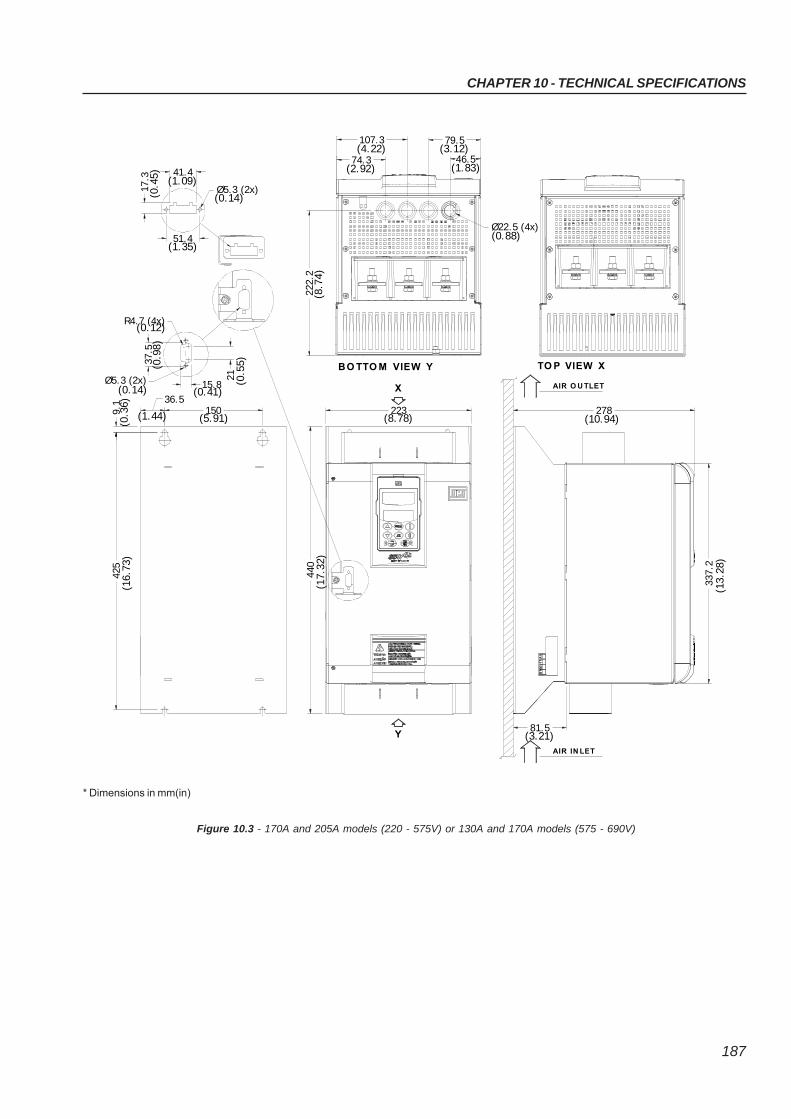
CHAPTER 10 - TECHNICAL SPECIFICATIONS
187
Figure 10.3 - 170A and 205A models (220 - 575V) or 130A and 170A models (575 - 690V)
* Dimensions in mm(in)
4 40
9.1
278
425
Y
(16.
73)
(17.
32)
337.
2
AIR IN LET
81.5(3.21)
(13.
28)
BO TTO M VIEW Y
223
51.4
37. 5
R4.7 (4x)
Ø5.3 (2x)
36.5
(0.3
6 )
(1.44)
(0.14)
(0.9
8)
(0.12)
15.8
150(5.91)
(0.41)
21 (0.5
5)
(8.78)
X
(1.35)
17.3
(0.4
5)
Ø5.3 (2x)(0.14)
41.4(1.09)
TO P VIEW X
(10.94)
AIR O U TLET
Ø22.5 (4x)
74.3
107.3
46.5
79.5(4.22)
(2.92)
(3.12)
(1.83)
(0.88)
222.
2(8
.74)
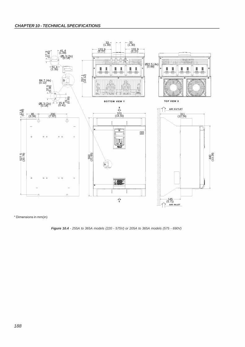
CHAPTER 10 - TECHNICAL SPECIFICATIONS
188
Figure 10.4 - 255A to 365A models (220 - 575V) or 205A to 365A models (575 - 690V)
* Dimensions in mm(in)
41.4
17.3
Ø5.3 (2x)
311
145
527.
5
550
(20.
78)
(21.
65)
20012.5
85(0.4
9)
(3.34) (7.87)
(0.12)R4.7 (4x)
Ø5.3 (2x)(0.14)
(0.9
8)37
.5
21
(0.41)15.8 (0
.55)
51.4(1.35)
370(14.55)
B O TTO M VIEW Y
440
AIR IN LET
(5.71)
(13 .
28)
AIR O U TLET
(12.24)
TO P VIEW X
(0.4
5) (1.09)
(0.14)
X
Y
Ø22.5 (4x)(0.88)
257.
1
133.9
33
133.9
33
(5.27)
(1.30)
(5.27)
(1.30)
(10.
12)
CHAPTER 10 - TECHNICAL SPECIFICATIONS
189
Figure 10.5 - 412A to 604A models
* Dimensions in mm(in)
BO TTO M VIEW Y
370(14.55)
X
650
(25.
5 9)
AIR IN LET
(5.71)145
AIR O U TLET
(13.67)
Y
12.5 200
(0. 4
9)
85(3.34) (7.87)
627.
5(2
4.70
)
347
540
(21.
26)
41.4
51.4
15.8
21
17.3
R4.7 (4x)
(0.14)
(0.12)
Ø5.3 (2x)
37.5
(0.9
8)
(1.35)
(0.4
5)
(0.5
5)
(0.41)
(0.14)Ø5.3 (2x)
(1.09)
TO P VIEW X
Ø22.5 (4x)33
33(1.30)
(1.30)
33
133.8(5.27)
(1.30)
292.
5(1
1.5 2
)

CHAPTER 10 - TECHNICAL SPECIFICATIONS
190
Figure 10.6 - 670A and 820A models
357(14.07)
204.3(8.04)
AIR IN LET
350(13.78)(3.74)
95
(0.4
9)12
.577
5(3
0.51
)
540(21.26)
795
(31.
30)
BO TTO M VIEW Y TO P VIEW X
X
Y
685
(31.
30)
R4.7 (4x)
Ø5.3 (2x)
17.3
(0.4
5)
(0.12)
(0.14)
(0.9
8)
Ø5.3 (2x)
21
(0.14)
15.8
18
(0.41)
(0.4
7)51.4
(1.35)(0
.55)
(1.09)
37.5
41.4Ø22.5 (4x)
(1.30)33
218.633
33
(1.30)
(1.30)
(8.61)
302.
4(1
1.91
)
AIR O U TLET
* Dimensions in mm(in)
CHAPTER 10 - TECHNICAL SPECIFICATIONS
191
Figure 10.7 - 950A models
* Dimensions in mm(in)
(13.65)347
AIR O U TLET
202
AIR IN LET(7.96)
148(5.83)
30(1.18)
754
(29.
68)
B O TTO N VIEW Y TO P VIEW X
X
845
(33.
27)
570(22.37)
Ø22.5 (4x)229
33(1.30)
(9.00) (0.88)
288
(11.
33)
810
25(0.98)
40084(3.31) (15.75)
(31 .
89)
Y
33(1.30)
(1.30)33
895
(35 .
23)
CHAPTER 10 - TECHNICAL SPECIFICATIONS
192
Figure 10.8 - 1100A and 1400A models
* Dimensions in mm(in)
371.
7(1
4.63
)
B O TTO M VIEW Y TO P VIEW Y
685.0(26.97)
1147
.0(4
5.16
)
X
50.0
172.3
(9.91)AIR IN LET
251.8
(1.97)
(6.78)
432.0(17.01)
1033
.8(4
0.70
)
Y
250.092.5(3.66) (9.84)22.0
111 0
.0(4
3.70
)
(0.87)(9.84)250.0
(1.30)33.0
33.0(1.30)
Ø22.5 (4x)228.7
(1.30)33.0
(9.00) (0.88)
AIR O U TLET AIR O U TLET
1207
.3(4
7.51
)
AIR O U TLET