Embed Size (px)
Citation preview

“S” TYPE“S” TYPE“S” TYPE“S” TYPE INSTINSTINSTINSTALLATIONALLATIONALLATIONALLATION MANUAL MANUAL MANUAL MANUAL
REVISION
11/2007


TABLE OF CONTENTS DESCRIPTION PAGE
INSTALLATION INSTRUCTIONS.........................................................................................1
DESPATCH POLICY FOR ACCEPTING BACK CHARGES ................................................2
GENERAL INFORMATION ...................................................................................................3-4
INSTALLATION OF BATCH OVENS ....................................................................................5-8
INSTRUCTIONS FOR MIXING AND CURING DES-CRETE INSULATING FLOOR MATERIAL................................................................................................................9
EXPLODED BODY ASSEMBLY ILLUSTRATION ................................................................10
FLOOR CHANNEL ASSEMBLY ILLUSTRATION.................................................................11
OVEN BODY PANEL ASSEMBLY ........................................................................................12-13
OVEN BODY SEALING PROCEDURE.................................................................................14
BODY CROSS SECTIONS FOR ASSEMBLY ......................................................................15-19
DUCTWORK ASSEMBLY ILLUSTRATIONS .......................................................................20-23
STANDARD DOOR HINGE ASSEMBLY ..............................................................................24
CONTROL AND HI-LIMIT THERMOCOUPLE MOUNTING.................................................25-27
FAN AIRFLOW SWITCH PIPE MOUNTING.........................................................................28
BBC AND FC FAN WHEEL POSITIONING..........................................................................29
SETTING HEATER BOX ON TOP OF OVEN.......................................................................30
OVEN AIRFLOW ADJUSTMENT..........................................................................................31-35
STANDARD SUPPLY AND RETURN DUCT/SLIDE
BASELINE ADJUSTMENT (SUPPLY ADJUSTABLE LOUVERS) .......................................36-58 STANDARD SUPPLY AND RETURN DUCT/SLIDE
BASELINE ADJUSTMENT (SUPPLY DIAMOND NOZZLES) ..............................................59-81 EXHAUST ASSEMBLIES ......................................................................................................82-84
MOTORIZED EXHAUST SET-UP.........................................................................................85
"S" TYPE OVEN FRONT AND SWING DOOR INSTALLATION..........................................86-87
SWING DOOR TROUBLESHOOTING INFORMATION.......................................................88-89
OPTIONAL "S" TYPE OVEN VERTICAL LIFT DOOR INSTALLATION...............................90-91
LIFT DOOR TROUBLESHOOTING INFORMATION............................................................92-94

I-235 (9/03) − 1 −
INSTALLATION INSTRUCTIONS The enclosed drawings, installation instructions and general information sheet are for use by the purchaser to enable them to contract local qualified personnel to erect an oven with a minimum of lost motion and without the services of a Despatch Engineer. It is suggested that the person selected to supervise the erection read the general information sheet and installation instructions thoroughly, referring to the specific drawings and details for your oven which should be included in this packet. Then follow the installation instructions as listed.
WARNING - THESE INSTRUCTIONS ARE BASED IN PART ON SAFETY CONSIDERATIONS, THEREFORE, ONLY QUALIFIED PERSONNEL SUCH AS EXPERIENCED RIGGERS SHOULD ATTEMPT THIS INSTALLATION.
If you receive your oven with body set up, then you may disregard those steps that have already been completed. However, we would recommend reading this manual completely to understand more about your oven and how it is built. Illustration 17 will be especially helpful in placing the heater box on top of the oven. The instructions are not intended to describe in detail or provide a solution for all the problems which could arise, as each unit presents its own peculiar problems. With good judgment and the use of the enclosed information, minimal difficulties should be encountered. If you would like to investigate the use of an experienced Despatch Installation Supervisor, contact our Service Department at the telephone number listed below. DESPATCH INDUSTRIES 8860 207th St. West
Lakeville, MN 55044 TELEPHONE: 952-469-5424 or Despatch Help Line: 1-800-473-7373

I-235 (9/03) − 2 −
DESPATCH POLICY FOR ACCEPTING BACK CHARGES Drawings and instructions supplied with the equipment ordered from Despatch generally result in trouble-free erection and start-up. However, occasionally discrepancies in materials supplied by Despatch will require rework or adjustment during installation. The policy in such an occurrence requires that the Purchaser receive prior authorization from Despatch for the cost of work to correct discrepancies. If there is any questions in regard to this policy, the Purchaser is instructed to contact the local Despatch representative. If erection and start-up has not been purchased from Despatch, we urge the purchase of the services of an erection supervisor. Generally, presence of an erection supervisor will minimize time lost should discrepancies occur. This also ensures efficient and correct erection of Despatch's ovens and furnaces.

I-235 (9/03) − 3 −
GENERAL INFORMATION 1. Panels are marked with part numbers (example 270832).
A. Part numbers are referenced by item numbers on the body drawings. 2. Return Duct items numbered 1, 2, 3, etc., indicate the recirculation or return duct which
corresponds to duct items on duct detail assembly drawings. Items are identified with part numbers.
3. Supply Duct items numbered 1, 2, 3, etc., indicate the supply duct which also
corresponds with drawings.
Exhaust Duct 1, 2, 3, etc., indicates exhaust duct. 4. Floor channels are not used at door (front) end of oven. On double end ovens, floor
channels are used on sides only. 5. Outside of oven panels are not painted unless ordered (refer to assembly drawing).
Attention must be paid to direction of panel joints. 6. When moving or storing oven parts, place panels on edge. This eliminates crushing of
panels and the desired numbered panel will be accessible without any shuffling. 7. Roof angles are designed to come to 1/2" of front and rear panels, i.e., roof angles are 1"
shorter than inside dimension of oven. 8. WEJ-IT anchors require a hole same diameter as the WEJ-IT and full length of
unthreaded part. Be sure wedges are fully seated in wedge pockets before inserting into hole. Insert WEJ-IT until washer is flat against work surface and tighten nut two to three full turns.
9. Self-drilling sheet metal screws are used for fastening all sheet metal components. It is
very important not to over-tighten the screw. The manufacturer recommends using torque-sensing drive tools which are easily adjustable to provide positive seating without stripping. Drill motors are not recommended. Tools with brakes are recommended to minimize the possibility of stripping. The following are guidelines only and the installer should always begin at a setting less than the guidelines listed below.
Panel Joints 85-95 in.lb. Torque
Double sheet (ie. Roof angles, floor channels): 45-55 in.lb. Torque Single sheet (ie. Inside flashing, outside flashing): 35-45 in.lb. Torque
10. Lap joints are used on duct connections. See duct assembly drawing for details. 11. A. 1/2" bolt requires 9/16" clearance drill and 7/16" body drill for tapping.
B. The new 1/2" Hex washer head, thread forming bolt requires a .469 diameter hole (15/32" drill).
C. 3/8" bolt requires 7/16" clearance drill and 21/64" body drill for tapping. D. The new 3/8" Hex washer head, thread forming bolt requires a .345 diameter hole
(11/32" drill).

I-235 (9/03) − 4 −
12. Gas-fired heaters model number indicates capacity in BTU per hour, i.e.,
DG-350 rated at 350,000 BTU per hour DG-500 rated at 500,000 BTU per hour DG-750 rated at 750,000 BTU per hour DG-1000 rated at 1,000,000 BTU per hour DG-1500 rated at 1,500,000 BTU per hour
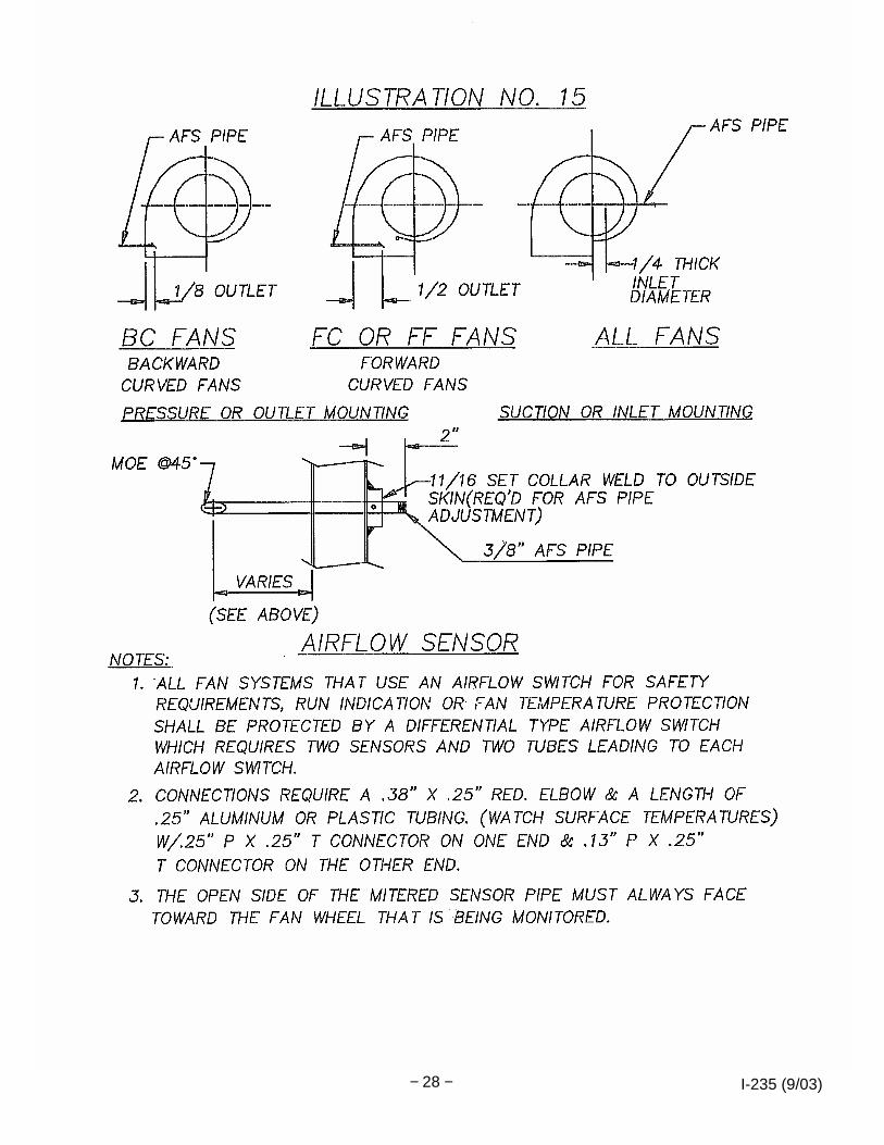
13. A.F.S. indicates airflow switch. Refer to Illustration #15. 14. A. If oven is to be mounted on wood floor, insurance requirements are such that 4" clay
building tile are required between wood floor and bottom of oven. Tile must be placed with openings in tile in line to permit free flow of air across the short axis of the oven. (Insulation batts for joint packing may be cut into strips with a “butcher knife” or equivalent, using a sawing motion.) B. It is required for ovens operating above 350°F to have an insulated floor. If the oven is to be mounted on an existing concrete floor, a pit must be added and filled with insulating floor material (“DES-CRETE” or other. See mixing & curing instructions on page 9).
15. Bolted connections on structural platforms, heater box support structural, etc., are for
erection ease only. These connections should be welded after erection unless noted otherwise on the drawings. This is especially critical at connections where fan vibration is possible.
16. The fresh air and exhaust damper settings should be in the closed position unless they
have been preset at the factory. Minimal adjustments to enhance certain requirements (ie: temperature uniformity, pressure balance) can be made. Allowing too much fresh air in can result in increased exterior wall temperatures. Opening the exhaust damper can introduce cool air from outside the oven that can affect temperature uniformity. See ‘Damper Operation’ in the Oven Instruction Manual for additional information.
17. If there is a variable speed drive for the recirculation fan it is important not to change the
fan speed without understanding the consequences. Pressure changes or changes in air velocity in the heater box can be affected. Consult the factory with any questions or concerns.
18. As part of a preventative maintenance program all fasteners should be inspected on a
regular basis. All loose fasteners should be tightened.

I-235 (9/03) − 5 −
INSTALLATION OF BATCH TYPE OVENS 1. Note overall dimensions of oven on assembly drawing and check for sufficient
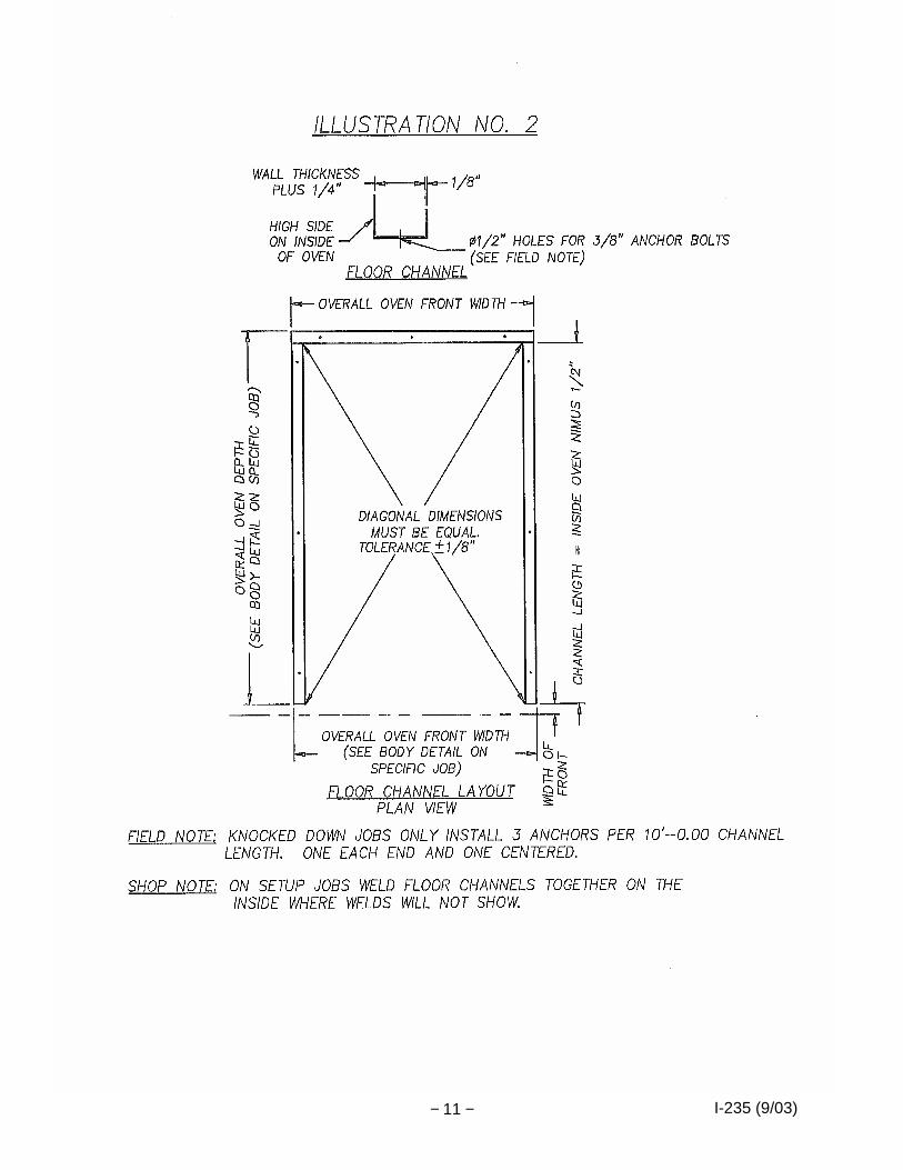
clearances from walls, overhead, etc. (6" minimum from wood construction). 2. With chalk line or scribe, lay out on floor the outside dimensions of the oven rear walls
and front. See Illustration #2 and body detail. 3. Working with the above markings add the outside chalk line for the sidewalls. If oven
has panel type floor, set panel floor and omit Steps 4 through 8. 4. Place sidewall floor channels on floor inside sidewall chalk lines. Sidewall channels are
1/2" shorter than the inside dimension of oven. The same applies to the rear wall channel. Refer to floor channel drawing.
5. Place rear wall floor channel on floor with the ends of the two sidewall channels and rear
channel touching. With a tape line, measure diagonally corner to corner of channels shifting sidewall channels until measurements are equal. Check again for sufficient aisle, overhead, etc., clearances.
6. Mark floor through predrilled holes in channels for location of anchor bolts. Three
anchors are required per ten lineal feet. 7. Scribe across end of floor channels for reference marks and with drill, drill holes for 3/8"
WEJ-ITS provided. 8. Replace channels over anchors and fasten with 3/8" nuts and washers. Recheck floor
channels for square. Holes in channel are enlarged to allow for errors in drilling concrete and expansion. Should floor have excessive pitch, level channels by using steel shims and grout with concrete grout mix to close the gap between the floor and floor channels. Gaps under floor channels must be sealed to eliminate fresh air leakage which will effect oven uniformity.
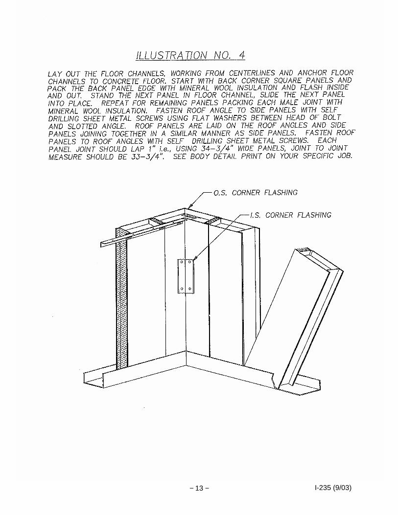
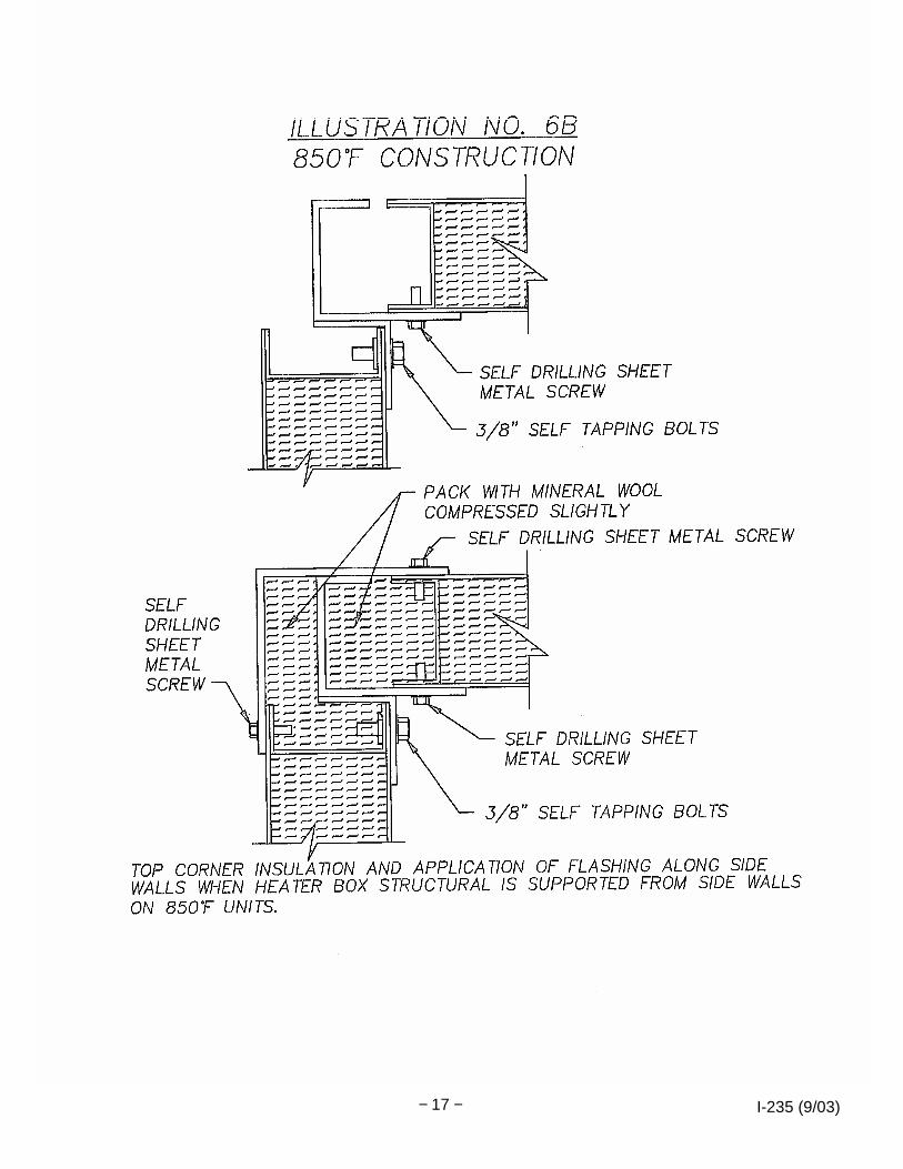
9. Starting with the rear corner panels, pack bottom void of panels with insulation provided,
and set the two corner panels in place. Square, flash inside, pack outside corner with insulation, and install outside flashing. See Illustrations #1, #3, #4, #5, #6, #6a, #6b and #7 for details of insulating and sealing panel joints.
10. Prepare next wall panel, packing with insulation. Slide panel in place. Each panel joint
lap approximately 1" depending on the type of panel (see body detail print). Illustrations #3 and #4 show panel engagement and assembly techniques.
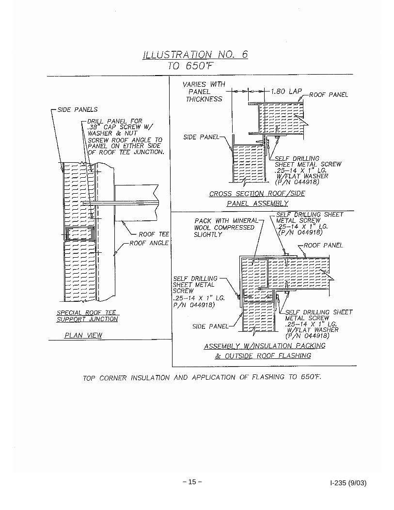
11. Bolt roof angle to wall and corner panels using 1/4" self-drilling sheet metal screws with
flat washer and, in special cases, 3/8" machine bolts and nuts at special roof tee junctions as noted, and use standard 3/8" flat washer under bolt head. If roof tees are required, at roof tee areas holes must be drilled on each side of the roof tee support in panels for fastening roof angles to panels. This will give a more positive hold to the roof panel. Refer to Illustration #6 for detail.
12. Referring to oven body detail and panel numbers, continue working both ways from first
corner panel (tying together with roof angle) until only the front section remains.
I-235 (9/03) − 6 −
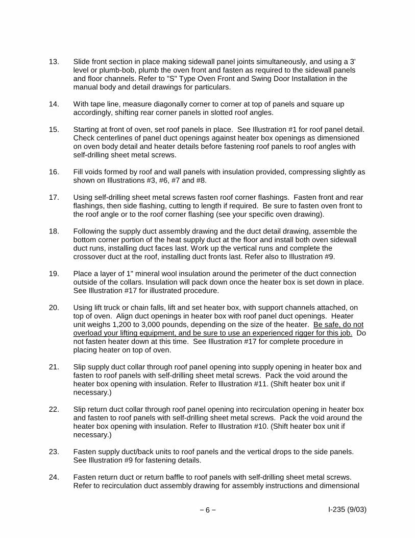
13. Slide front section in place making sidewall panel joints simultaneously, and using a 3'
level or plumb-bob, plumb the oven front and fasten as required to the sidewall panels and floor channels. Refer to "S" Type Oven Front and Swing Door Installation in the manual body and detail drawings for particulars.
14. With tape line, measure diagonally corner to corner at top of panels and square up
accordingly, shifting rear corner panels in slotted roof angles. 15. Starting at front of oven, set roof panels in place. See Illustration #1 for roof panel detail.
Check centerlines of panel duct openings against heater box openings as dimensioned on oven body detail and heater details before fastening roof panels to roof angles with self-drilling sheet metal screws.
16. Fill voids formed by roof and wall panels with insulation provided, compressing slightly as
shown on Illustrations #3, #6, #7 and #8. 17. Using self-drilling sheet metal screws fasten roof corner flashings. Fasten front and rear
flashings, then side flashing, cutting to length if required. Be sure to fasten oven front to the roof angle or to the roof corner flashing (see your specific oven drawing).
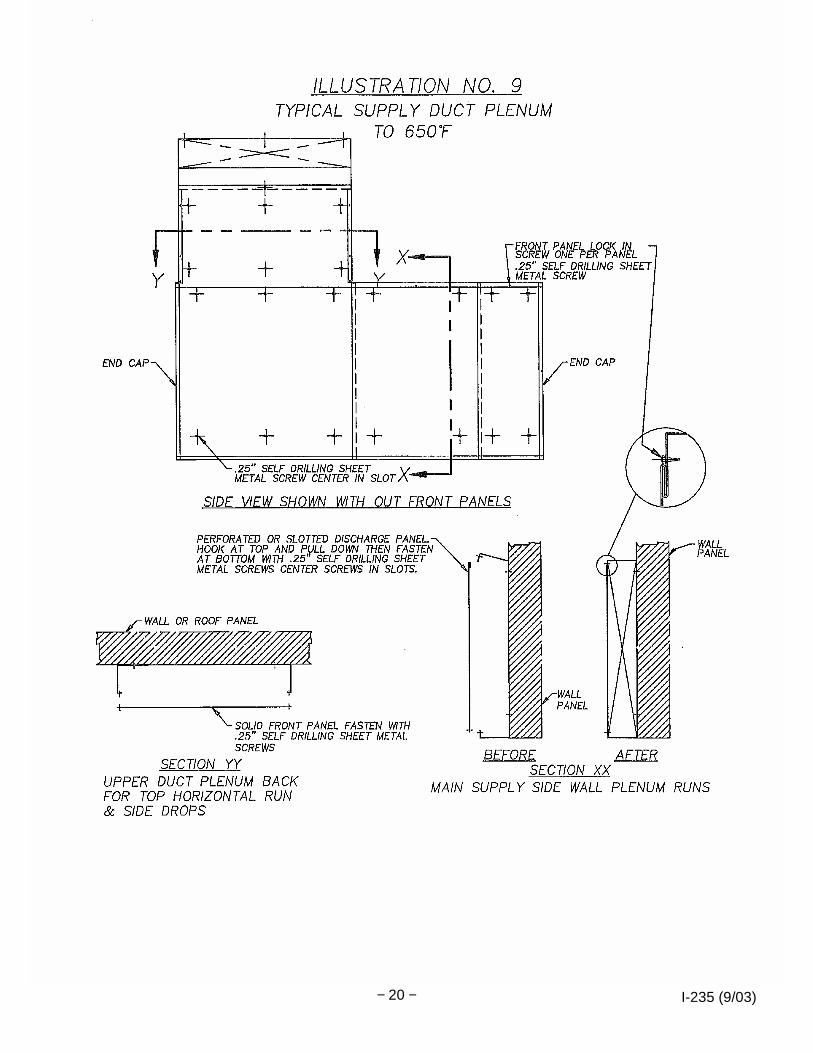
18. Following the supply duct assembly drawing and the duct detail drawing, assemble the
bottom corner portion of the heat supply duct at the floor and install both oven sidewall duct runs, installing duct faces last. Work up the vertical runs and complete the crossover duct at the roof, installing duct fronts last. Refer also to Illustration #9.
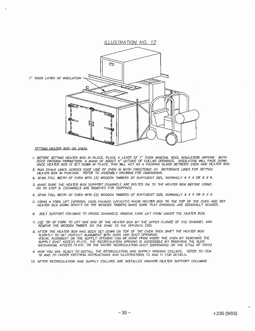
19. Place a layer of 1" mineral wool insulation around the perimeter of the duct connection
outside of the collars. Insulation will pack down once the heater box is set down in place. See Illustration #17 for illustrated procedure.
20. Using lift truck or chain falls, lift and set heater box, with support channels attached, on
top of oven. Align duct openings in heater box with roof panel duct openings. Heater unit weighs 1,200 to 3,000 pounds, depending on the size of the heater. Be safe, do not overload your lifting equipment, and be sure to use an experienced rigger for this job. Do not fasten heater down at this time. See Illustration #17 for complete procedure in placing heater on top of oven.
21. Slip supply duct collar through roof panel opening into supply opening in heater box and
fasten to roof panels with self-drilling sheet metal screws. Pack the void around the heater box opening with insulation. Refer to Illustration #11. (Shift heater box unit if necessary.)
22. Slip return duct collar through roof panel opening into recirculation opening in heater box
and fasten to roof panels with self-drilling sheet metal screws. Pack the void around the heater box opening with insulation. Refer to Illustration #10. (Shift heater box unit if necessary.)
23. Fasten supply duct/back units to roof panels and the vertical drops to the side panels.
See Illustration #9 for fastening details.
24. Fasten return duct or return baffle to roof panels with self-drilling sheet metal screws. Refer to recirculation duct assembly drawing for assembly instructions and dimensional

I-235 (9/03) − 7 −
location. 25. Secure lap joints with self-drilling sheet metal screws. 26. Position perforated or louvered air discharge supply duct faces end to end, referring to
assembly drawing for dimensions and using 3' level , level ducts. Fasten ducts to sidewall panels with self-drilling sheet metal screws. See Illustrations #9 and #11 for details.
27. Supply/discharge opening settings can be made later after fan is operating. See step 38. 28. Anchor heater box support columns. 29. Connect exhaust duct or exhaust fan and damper linkage to oven. Mount inside exhaust
baffle plate over exhaust opening (small opening in ceiling). Refer to oven damper linkage picture reference in this manual showing exhaust damper set-up, or detail drawings if linkage is complicated. Refer to pages 81, 82, 83 and 84.
30. Refer to door and front installation in manual.
Options are as follows:
· "S" Type Oven Front and Swing Door installation · "S" Type Oven Vertical Lift Door Installation
31. If a Descrete poured insulated floor is used, set tracks (if used) into position, referring to
end elevation of oven assembly drawing for dimensional data and check these dimensions with the truck that will be used on the job. Then pour floor. Refer to mixing and curing instructions included in this manual. Purchaser to furnish all Portland cement required, as due to spoilage, it is not practical to ship Portland cement with oven.
32. Carefully locate and mount control and high limit thermocouple (refer to oven assembly
drawing for location) and fasten to supply duct face. See detail Illustration #13 and #14. Do not kink. Avoid bends with a radius smaller than 1". See Illustration #14.
33. On electric models, make electric service connections, referring to electrical drawings for
connection points and total load amperage. On gas models, make electrical and gas connections, referring to electric and piping drawings. On gas models, a manual shut-off valve immediately ahead of burner piping is required.
34. For exhaust fan locations refer to the assembly drawing. Smaller direct drive exhaust
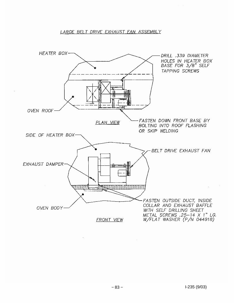
fans mount directly over oven panel exhaust opening and exhaust fan is fastened to roof panel with self-drilling sheet metal screws. Larger belt driven exhaust fans will mount to a structural base which sets on top of the oven. Holes must be drilled into the heater box side for mounting base steel and fastened or welded to the oven roof flashing at the opposite end. Refer to pages 81, 82 and 83.
35. Large exhaust fans require an inlet duct assembly which sets in the roof opening and laps over the exhaust fan inlet collar. Refer to page 83.
36. Field mounting of the inside exhaust baffle is required. Refer to pages 81, 82 or 83 for
further detail and mounting instructions.

I-235 (9/03) − 8 −
37. Run exhaust stack to exterior of building as required. Avoid horizontal runs and elbows
wherever possible. When running exhaust stack through wood ceilings, partitions, etc., distance from wood should be at least 6" on all sides. Refer also to local ordinances. See recommended exhaust duct installation sheet in the operating instruction book.
38. Refer to Operating Instruction Book for start-up procedure. 39. Initial Air Adjustment—Set all duct slots or perforations to give uniform air velocity. See
illustration titled Oven Airflow Adjustment located at the end of the installation manual for baseline ductwork settings. Refer to pages 31 through 80.

I-235 (9/03) − 9 −
INSTRUCTIONS FOR MIXING AND CURING "DES-CRETE" INSULATING FLOOR MATERIAL
MIXING 1. For Hard Floors - Heavy Traffic
- Three (3) 50 pound bags "DES-CRETE" to one (1) 98 pound bag Portland cement, and approximately twenty-one (21) gallons water.
2. For Medium Floors - Light Traffic
- Four (4) 50 pound bags "DES-CRETE" to one (1) 98 pound bag Portland cement, and approximately twenty-six (26) gallons of water.
Place the "DES-CRETE" in a mortar mixer first and add the Portland gradually. When these ingredients are well mixed, slowly add water. DO NOT ADD TOO MUCH WATER. Test mixture as follows:
- Form a ball out of the mixture. - Toss it about 12" into the air and catch it in your hand. - If it breaks apart or crumbles, it is too dry. - If it flattens out or deforms considerably, it is too wet. - The ball should remain reasonably intact if the mixture is correct.
CURING 1. Air dry for twenty-four (24) hours at room temperature. 2. Heat oven to 200°F and hold at this temperature for 1-1/2 hours for every inch of floor
thickness (3" thick floor = 4-1/2 hours). 3. Increase temperature 50°F per hour until maximum temperature is reached. SURFACE CONDITIONING After curing, the surface of the floor may be sprayed or painted with a solution of Silicate of Soda—diluted one-to-one with water. This will further seal the surface and prevent dusting.

I-235 (9/03) − 10 −
I-235 (9/03) − 11 −

I-235 (9/03) − 12 −
I-235 (9/03) − 13 −

I-235 (9/03) − 14 −
I-235 (9/03) − 15 −

I-235 (9/03) − 16 −
I-235 (9/03) − 17 −

I-235 (9/03) − 18 −
I-235 (9/03) − 19 −
I-235 (9/03) − 20 −

I-235 (9/03) − 21 −

I-235 (9/03) − 22 −

I-235 (9/03) − 23 −

I-235 (9/03) − 24 −

I-235 (9/03) − 25 −

I-235 (9/03) − 26 −

I-235 (9/03) − 27 −
I-235 (9/03) − 28 −

I-235 (9/03) − 29 −
I-235 (9/03) − 30 −

I-235 (9/03) − 31 −
OVEN AIRFLOW ADJUSTMENT
1. THE PURPOSE OF ADJUSTABLE AIRFLOW
a. Ability to get the best temperature and airflow uniformity.
b. Ability to "spot heat" special areas or specific parts of load.
c. Ability to prevent air flowing out or sucking in through the entrance and exit openings in the oven.
2. NO FACTORY ADJUSTMENT
Most ovens that have final assembly in the field have not had the louvers adjusted at all since the heater boxes have not been installed on the oven before shipment. The louvers on some of the smaller, shipped assembled, more standard ovens (models RS, S (PS), PW, PC, and VR), where ductwork is already installed or heater source is incorporated with the oven, have been basically pre-set to baseline adjustments (no uniformity tests have been performed unless it is purchased as an extra).
3. PREFERRED METHOD—FACTORY SPECIALISTS
We recommend using our factory specialists for start-up and adjustment. Our people are well trained and have many years of experience. We feel that an experienced Despatch field supervisor will save the customer inconvenience, confusion and costs besides getting a proper installation that will be covered under warranty and give many years of trouble free operation. If this service has not been purchased with the equipment it may be obtained by contacting the Despatch Field Service Department for price and availability.
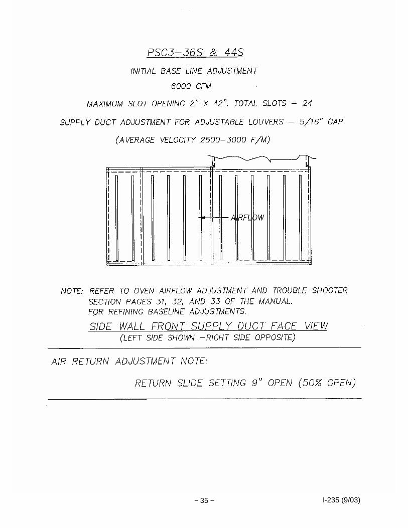
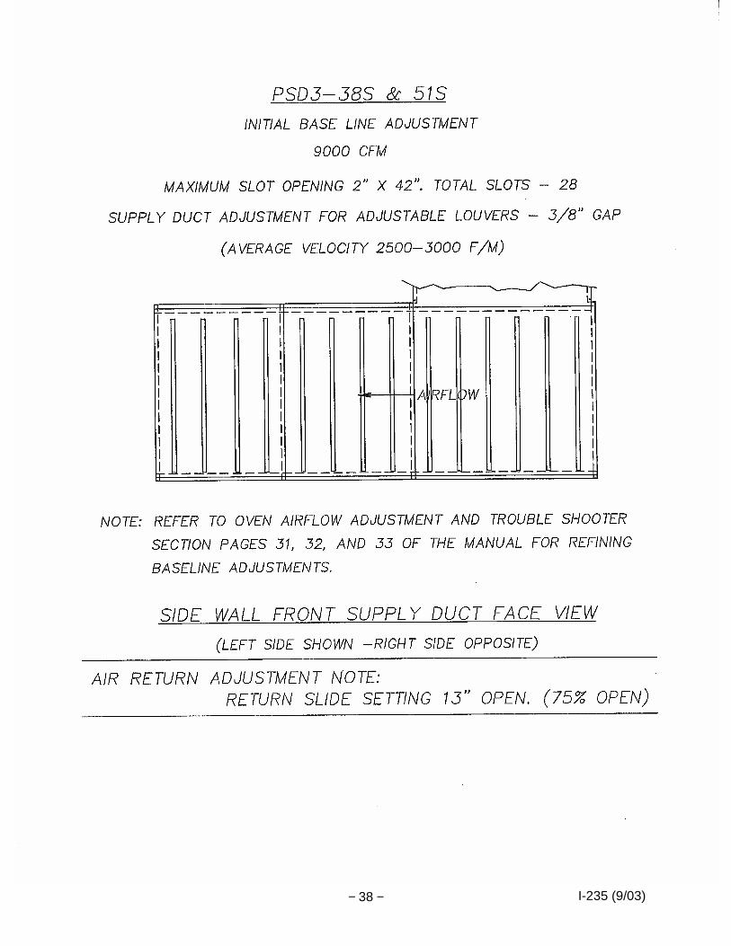
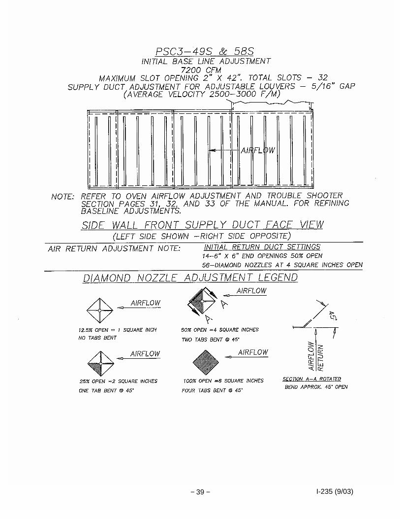
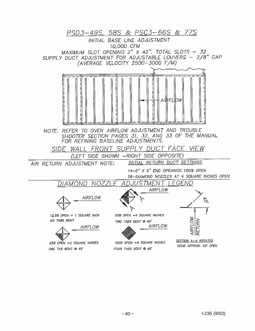
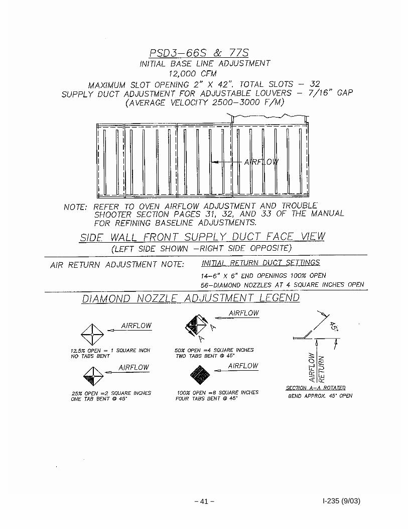
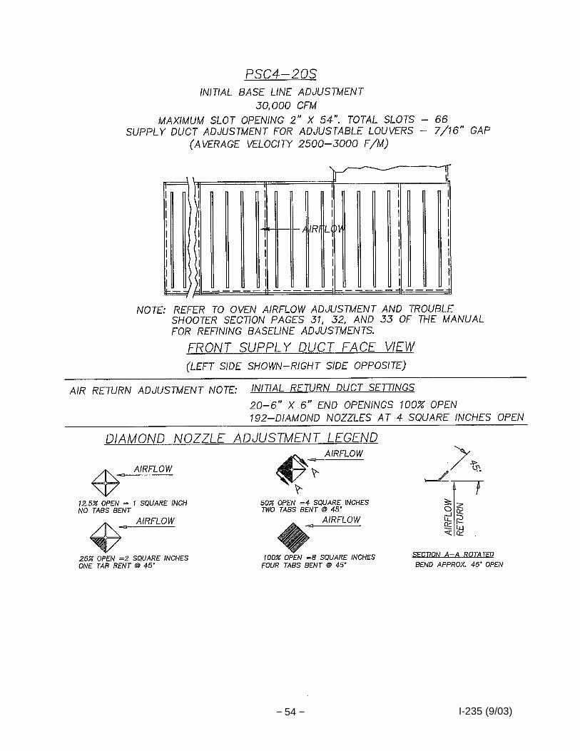
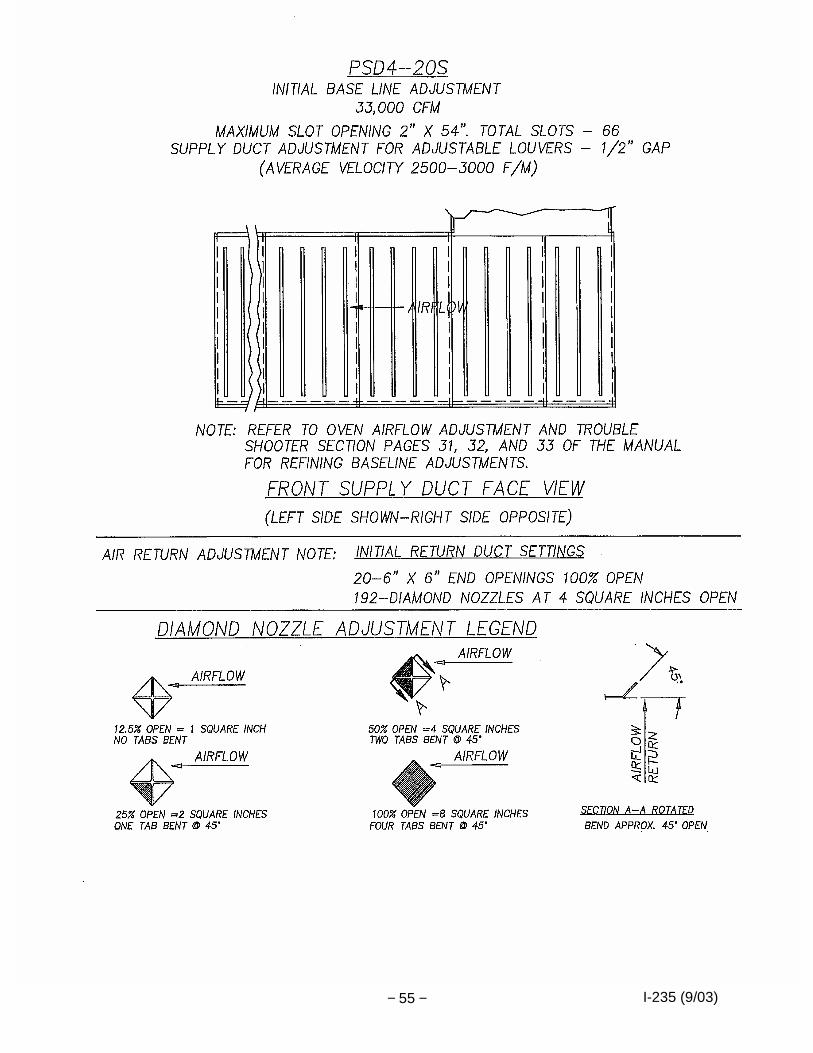
4. GENERAL GUIDELINES—SUPPLY AIR ADJUSTMENT
The adjustment of supply louvers is directly related to temperature uniformity in the work chamber. A general guideline is that more heat is required next to doors, windows and outside walls so, therefore, more air is required to deliver that heat. The supply duct chart shows the relationship of slot openings in several different shapes of ducts.
5. GENERAL GUIDELINES—RETURN AIR ADJUSTMENT
The return ducts are not as critical in setting as long as they are opened up enough to eliminate a restrictive condition that may cut down the amount of air being handled by the fan or result in a pressurized condition within the work chamber. Initial setting of return louvers should be 50% more open than supply louvers—final adjustment may be required.
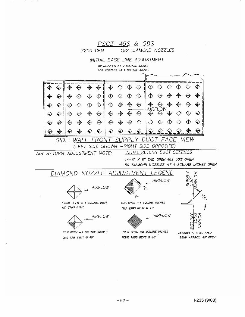
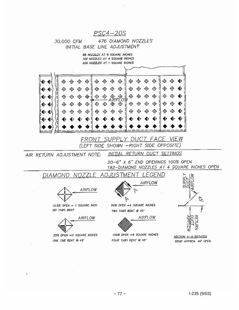
6. Refer to the following pages for baseline settings that match your ductwork discharge
options (louvers or diamond nozzle options). Use adjustment tool (P/N 211834) for adjusting diamond nozzle ports as noted on the following pages

I-235 (9/03) − 32 −
AIRFLOW TROUBLE SHOOTER
Conditions
Actions BATCH OVENS A. Non-uniform work chamber
1. Check to get a slightly positive chamber pressure by
closing down exhaust or opening up fresh air. See damper instructions, also.
2. Adjust supply louvers—open for cold spots—close for hot spots. If necessary, adjust return louvers in the same manner.
B. Cold by door
1. See A-1. 2. Check door seals. 3. Open supply louvers close to door.
C. Positive pressure in chamber
1. Close fresh air damper. 2. Open exhaust damper. 3. Check joining connection on return air into heater box
(check with smoke around outside of heater box). If leaky, fit joint and then reseal.
D. Negative pressure in chamber
1. Close exhaust damper. 2. Open fresh air damper. 3. Open supply louvers slightly.
CONTINUOUS OVENS E. Cold on ends
1. Close down the exhaust damper. 2. Open fresh air damper.
F. Heat blowing out on ends
1. Close fresh air damper. 2. Open exhaust damper. 3. See C-3. 4. Adjust supply louvers by end opening. 5. Make sure cold air is not being pulled in at the bottom
of the end opening—adjust louver if necessary. ALL OVENS G. Will not reach operating temperature
1. Close exhaust damper. 2. Close fresh air damper. 3. Quite often the cause is the burner not up to capacity
because of gas pressure or burner adjustment. If problem persists after assurance has been made that the unit BTUH OUTPUT is the same as on the rating plate, proceed to Number 4.
4. See C-3. 5. Check the supply duct joint between the heater box
and the oven. If leaky, fix joint and then seal.
WARNING Too much positive pressure in an oven creates a high outer skin temperature because hot air is forced out through panel joints and around door seal and could possibly warp the front.

I-235 (9/03) − 33 −

I-235 (9/03) − 34 −
I-235 (9/03) − 35 −

I-235 (9/03) − 36 −

I-235 (9/03) − 37 −
I-235 (9/03) − 38 −
I-235 (9/03) − 39 −
I-235 (9/03) − 40 −
I-235 (9/03) − 41 −

I-235 (9/03) − 42 −

I-235 (9/03) − 43 −

I-235 (9/03) − 44 −

I-235 (9/03) − 45 −

I-235 (9/03) − 46 −

I-235 (9/03) − 47 −

I-235 (9/03) − 48 −

I-235 (9/03) − 49 −

I-235 (9/03) − 50 −

I-235 (9/03) − 51 −

I-235 (9/03) − 52 −

I-235 (9/03) − 53 −
I-235 (9/03) − 54 −
I-235 (9/03) − 55 −

I-235 (9/03) − 56 −

I-235 (9/03) − 57 −

I-235 (9/03) − 58 −

I-235 (9/03) − 59 −

I-235 (9/03) − 60 −

I-235 (9/03) − 61 −
I-235 (9/03) − 62 −

I-235 (9/03) − 63 −

I-235 (9/03) − 64 −

I-235 (9/03) − 65 −

I-235 (9/03) − 66 −

I-235 (9/03) − 67 −

I-235 (9/03) − 68 −

I-235 (9/03) − 69 −

I-235 (9/03) − 70 −

I-235 (9/03) − 71 −

I-235 (9/03) − 72 −

I-235 (9/03) − 73 −

I-235 (9/03) − 74 −

I-235 (9/03) − 75 −

I-235 (9/03) − 76 −
I-235 (9/03) − 77 −

I-235 (9/03) − 78 −

I-235 (9/03) − 79 −

I-235 (9/03) − 80 −

I-235 (9/03) − 81 −

I-235 (9/03) − 82 −
I-235 (9/03) − 83 −

I-235 (9/03) − 84 −
Side Elevation – Typical motorized damper assembly with options (exhaust damper shown)
NOTE: Refer to Operating Manual for drawing showing mounting setup and hardware details.
I-235 (9/03) − 85 −
S-TYPE OVEN FRONT AND SWING DOOR INSTALLATION
The following is a narrative describing the steps for assembly and adjustment of standard oven fronts and swing doors. Step #
Description
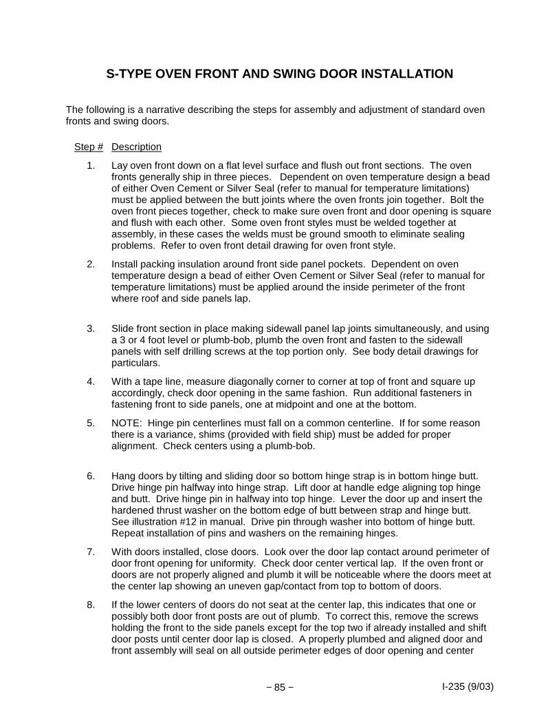
1.
Lay oven front down on a flat level surface and flush out front sections. The oven fronts generally ship in three pieces. Dependent on oven temperature design a bead of either Oven Cement or Silver Seal (refer to manual for temperature limitations) must be applied between the butt joints where the oven fronts join together. Bolt the oven front pieces together, check to make sure oven front and door opening is square and flush with each other. Some oven front styles must be welded together at assembly, in these cases the welds must be ground smooth to eliminate sealing problems. Refer to oven front detail drawing for oven front style.
2.
Install packing insulation around front side panel pockets. Dependent on oven temperature design a bead of either Oven Cement or Silver Seal (refer to manual for temperature limitations) must be applied around the inside perimeter of the front where roof and side panels lap.
3.
Slide front section in place making sidewall panel lap joints simultaneously, and using a 3 or 4 foot level or plumb-bob, plumb the oven front and fasten to the sidewall panels with self drilling screws at the top portion only. See body detail drawings for particulars.
4.
With a tape line, measure diagonally corner to corner at top of front and square up accordingly, check door opening in the same fashion. Run additional fasteners in fastening front to side panels, one at midpoint and one at the bottom.
5.
NOTE: Hinge pin centerlines must fall on a common centerline. If for some reason there is a variance, shims (provided with field ship) must be added for proper alignment. Check centers using a plumb-bob.
6.
Hang doors by tilting and sliding door so bottom hinge strap is in bottom hinge butt. Drive hinge pin halfway into hinge strap. Lift door at handle edge aligning top hinge and butt. Drive hinge pin in halfway into top hinge. Lever the door up and insert the hardened thrust washer on the bottom edge of butt between strap and hinge butt. See illustration #12 in manual. Drive pin through washer into bottom of hinge butt. Repeat installation of pins and washers on the remaining hinges.
7.
With doors installed, close doors. Look over the door lap contact around perimeter of door front opening for uniformity. Check door center vertical lap. If the oven front or doors are not properly aligned and plumb it will be noticeable where the doors meet at the center lap showing an uneven gap/contact from top to bottom of doors.
8.
If the lower centers of doors do not seat at the center lap, this indicates that one or possibly both door front posts are out of plumb. To correct this, remove the screws holding the front to the side panels except for the top two if already installed and shift door posts until center door lap is closed. A properly plumbed and aligned door and front assembly will seal on all outside perimeter edges of door opening and center
I-235 (9/03) − 86 −
Step #
Description door lap. At this time make sure you install and tighten down the remaining fasteners into oven front and side panels for final connection once the front is plumb.
9.
Final oven front mounting is achieved by securing the oven front mounting angles located at the base of each door post to the factory floor. Drill 5/8” holes in the concrete factory floor for 5/8” WEJ-IT anchors supplied with field ship. Insert anchor with washer and nut, with the nut at the top of the anchor lightly tap anchor into hole using top of nut so threads are protected. Drive in anchor till nut makes contact with angle and tighten down nut.
10.
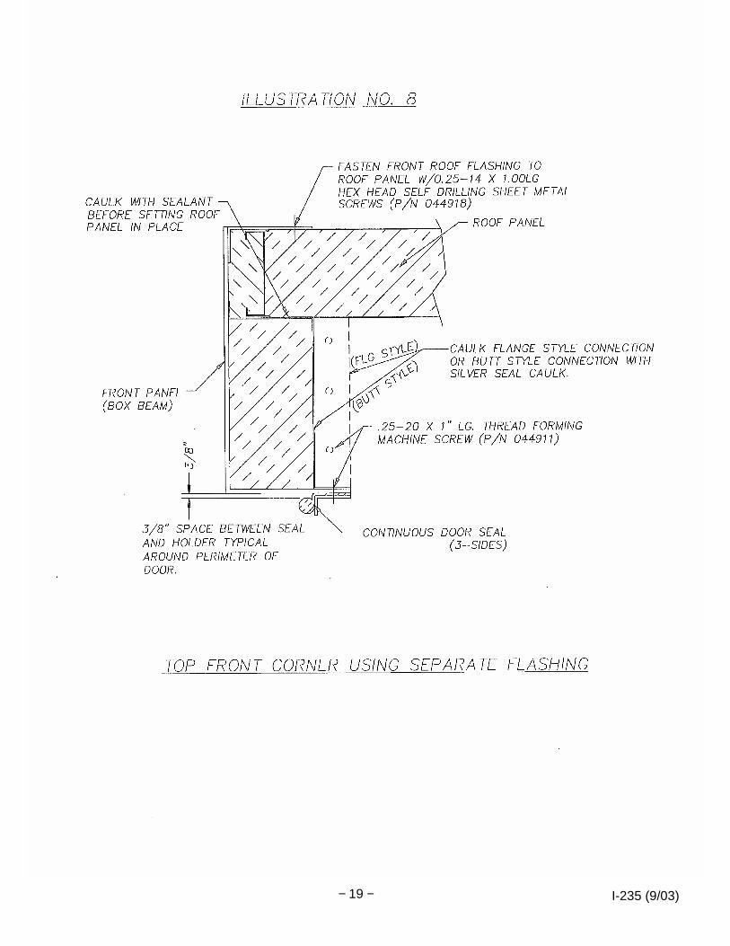
Inside seal installation. Install center vertical lapping door seal and perimeter door seals with seal holders and fasteners supplied. Refer to door and front assembly drawing and illustration #8 in the manual for details. Using a 3/8” spacer, gap the door seal away from the door frame, this will allow the door seal to make better contact with the door face due to door and frame clearances. Adjust door seals where the seals come in contact with the door face with a small amount of compression. Seals should not be over compressed to cause total flattening of the seal ball. Seals should only form a slight oval for better seal life.
11.
Open and close doors 4-6 times each time checking for proper sealing. Check to make sure latches are mounted properly. The small door assemblies have only one latch assembly at the top of the doors. Make sure the latch is adjusted and shimmed properly so the bottom of door is not forced out. Latch should be adjusted for easy opening of doors and not overly tightened. Large door assemblies have two latch assemblies; one at the top and one at the bottom with a floor strike anchored into the factory floor. Latches should be adjusted for easy opening of doors and not overly tightened to cause the doors to bow and cause a gap or uneven contact where doors meet at the center of the doors.
12.
For more information on door and front adjustment refer to “SWING DOOR TROUBLE SHOOTING INFORMATION” found in the manual.

I-235 (9/03) − 87 −
SWING DOOR TROUBLESHOOTING INFORMATION
Please Note : There can be a number of reasons or combination of reasons for swing door and oven front problems. They include: door alignment, door not sealing, door or oven front warpage, and possibly oven uniformity problems. One thing to keep in mind while you are investigating these potential adjustments/fixes is to make sure that you only make one change at a time; both marking and logging each change in case you have to go back to your original settings. If you make too many changes at one time, you may find yourself not really knowing what fixed the problem, or worse yet, only shifting or complicating the problem. Following is a list of items to check out : The first thing to check is the oven pressure. Many times you will find this is where the problem originates, especially if you are having uniformity problems. It is easy to help your uniformity by opening the fresh air in order to overcome outside air leakage, but this also pressurizes the oven and in some extreme cases causes excessive outside oven skin temperatures and door leakage which can create door and oven front problems. To address this condition: 1. Make sure the fresh air inlet(s) on the heating units/box(es) include a damper blade(s). 2. Fresh air damper should initially be closed. (Note: damper blade may be cutaway for
process requirements and/or safety requirements.) 3. Exhaust air damper should also initially be closed. (Note: damper blade may be cutaway for
process requirements and/or safety requirements.) Depending on the pressure drop in the exhaust stack run, you may need to open the exhaust damper somewhat in order to create a slight negative pressure in the oven. Positive/negative pressure can be realized/noted by excessive outside oven skin temperatures, or air moving in or out around panel joints, flashing joints or areas around the door perimeter. The simplest way to test oven pressure is with a smoke test checking areas where leakage would be most evident. This can be viewed on the outside of the oven watching the smoke being either pulled in or blown out away from the areas tested.
Note: Oven should normally be set neutral to sligh tly negative for best door sealing results. · Review door and front adjustment instructions, which are found in the "S" Oven Manual ,
provided with the equipment. These instructions should have been followed prior to the initial heating of the oven. Please review these Instructions before preceding any further in order to familiarize yourself with the door adjustment procedures.
· Make sure that the inside perimeter oven seal, center door seal and the drag seals have
been installed properly on the doors and front. Misadjusted door seals will cause the doors to bind up prior to closing. Inside perimeter seals should be gapped approximately 3/8” away from inside door frame so the seals do not get pinched between the door and framed opening on the hinged side of the doors. Refer to illustration #8 in the ”S” Oven Manual.
· Check doorframe with a straight edge to make sure doorframe is plumb and square and not
crowned (full height and width.) Check both the right and left side and the top and bottom. Check the oven doors in the same fashion. Check when the oven is cold and also when oven is hot for comparison.
I-235 (9/03) − 88 −
· With the oven cold and the front plumbed the door flanges should make contact with the oven front and the vertical center door lap should make even contact top to bottom. If not check to see that the hinges are adjusted properly and tightened down, make sure the hinge pin centerlines vertically fall on the same centerline. This can be measured with a plumb line off the front comparing the hinge pin centers. If the hinges fall off a common centerline the hinges must be shimmed individually.
· Checks to make sure latches are mounted properly. The small door assemblies have only
one latch assembly at the top of the doors. Make sure the latch is adjusted and shimmed properly so the bottom of door is not forced out. Latch should be adjusted for easy opening of doors and not overly tightened. Large door assemblies have two latch assemblies; one at the top and one at the bottom with a floor strike anchored into the factory floor. Latches should be adjusted for easy opening of doors and not overly tightened to cause the doors to bow and cause a gap or uneven contact where doors meet at the center of the doors.
· With the oven cold, from inside the oven check the internal perimeter oven front seals and
the center door seal for complete sealing against the door perimeter. Seals should not be over compressed to cause total flattening of seals. Seals should form a slight oval. Cycle door 6 to 8 times. Since seals are new, they will compress some and may need readjustment, especially the inside front perimeter seal. Double check the outside door drag seals (all designs) to make sure factory floor contact is made. Any adjustments to doors or seals require that you recheck all seals again for proper sealing.
· Oven pressure - how positive is the oven? Excessive positive pressure could result in
warpage of the doors and/or oven front. This problem would normally show up at the top of the door where the pressure and heat have more impact due to the free span of the wide opening and where thermo expansion would be most noticeable. Generally, if a sealing problem exists in the lower areas at the sides of the door, the problem is due to the door not sealing or barely sealing from the start, and the problem just worsens as you increase oven temperature or pressure. Once again, if the oven front or doors are not properly aligned it will be noticeable where the doors meet at the center vertical lap showing an uneven gap/contact from top to bottom of doors possibly preventing doors from properly sealing.
If you have any further questions, or you do not understand the theory of the door design or the explanations above, please do not hesitate to give us a call. Feel free to contact us thru our 1-800 number found in the manual.

I-235 (9/03) − 89 −
OPTIONAL S-TYPE OVEN VERTICAL LIFT DOOR INSTALLATIO N The following is a narrative describing the steps for the adjustment of a lift door. Step #
Description
1.
Lay oven front down on a flat level surface and flush out front sections. The oven fronts generally ship in three pieces. Dependent on oven temperature design a bead of either Oven Cement or Silver Seal (refer to manual for temperature limitations) must be applied between the butt joints where the oven fronts join together. Bolt the oven front pieces together, check to make sure oven front and door opening is square and flush with each other. Some oven front styles must be welded together at assembly, in these cases the welds must be ground smooth to eliminate sealing problems. Refer to oven front detail drawing for oven front style.
2.
Install packing insulation around front side panel pockets. Dependent on oven temperature design a bead of either Oven Cement or Silver Seal (refer to manual for temperature limitations) must be applied around the inside perimeter of the front where roof and side panels lap.
3.
Slide front section in place making sidewall panel lap joints simultaneously, and using a 3 or 4 foot level or plumb-bob, plumb the oven front and fasten to the sidewall panels with self drilling screws at the top portion only. See body detail drawings for particulars.
4.
With a tape line, measure diagonally corner to corner at top of front and square up accordingly, check door opening in the same fashion. Run additional fasteners in fastening front to side panels, one at midpoint and one at the bottom.
5.
Final oven front mounting is achieved by securing the oven front mounting angles located at the base of each door post to the factory floor. Drill 5/8” holes in the concrete factory floor for 5/8” WEJ-IT anchors supplied with field ship. Insert anchor with washer and nut, with the nut at the top of the anchor lightly tap anchor into hole using top of nut so threads are protected. Drive in anchor till nut makes contact with angle and tighten down nut.
6.
Connect the chain to the door, adjusting connecting rods by lowering the chains with the pneumatic cylinder.
7.
Remove door roller rests before the following adjustments.
8.
Raise the door and level it with the eye bolts, approximately 1" from floor.
9.
Adjust the positions of the sprockets that carry the chains holding the door as follows: Move the eye bolts in the slots to the front of the door. Next, move the top sprockets so that the centerline of the chain is vertical from the door when the door is pushed up tight against the oven front. The positions of the sprocket and eye bolt should create a pendulum causing the door to swing in towards the oven front.
10.
Lower the door so it is 1/2" from the floor. Push the door against the front, making sure that the pins/rollers on the door do not interfere with the roller guides. Push the door flush against the front using a man lift or fork truck.

I-235 (9/03) − 90 −
Step #
Description
11. Adjust the roller rests, duplicating the height and angle (approximately 30°-45°) on each side of the door.
12.
Lower the door and ensure that the door cams in against the oven front. Verify the distance from the exterior of the door to the oven front is the same side to side, and that the bottom seal is lightly engaging the floor.
13.
From the inside of the oven, inspect the outside seal on 500°F and 650°F ovens, or the inside breaker seal on 850°F designs, on the oven front to verify when the door is down and sealed as it engages the door and front. Look for light shining through gaps on 500°F and 650°F designs. You will need light inside the oven to view the 850°F breaker seal style around the inside perimeter of the door opening to view seal contact to lift door.
14.
Adjust the outside door seals as required to make a solid fit-up on the oven front for all temperature designs.
15.
When initially starting the oven verify the fresh air damper is closed and the exhaust damper is 50% open. The oven must not be over-pressurized.
16.
Run the oven from ambient to its maximum temperature in 200°F increments, inspecting the front and seals for leakage at each step.
17.
For more information on door and front adjustment, refer to "LIFT DOOR TROUBLESHOOTING INFORMATION " found in the manual.
Caution: If the oven is run in an over-pressurized condition, infiltration of hot air may take place at the door or at the corner flashing, discoloring the oven and/or warping the door front and door.

I-235 (9/03) − 91 −
LIFT DOOR TROUBLESHOOTING INFORMATION Please Note : There can be a number of reasons or a combination of reasons for lift door and oven front problems. They include: door not sealing, door or oven front warpage, and possibly oven uniformity problems. One thing to keep in mind while you are investigating these potential adjustments/fixes is to make sure that you only make one change at a time; both marking and logging each change in case you have to go back to your original settings. If you make too many changes at one time, you may find yourself not really knowing what fixed the problem, or worse yet, only shifting or complicating the problem. Following is a list of items to check out : The first thing to check is the oven pressure. Many times you will find this is where the problem originates, especially if you are having uniformity problems. It is easy to help your uniformity by opening the fresh air in order to overcome outside air leakage, but this also pressurizes the oven and, in some extreme cases, causes excessive outside oven skin temperatures and door leakage, which can create door and oven front problems. To address this condition: 1. Make sure the fresh air inlet(s) on the heating units/box(es) include a damper blade(s). 2. Fresh air damper should initially be closed. (Note: damper blade may be cutaway for
process requirements and/or safety requirements.) 3. Exhaust air damper should also initially be closed. (Note: damper blade may be cutaway for
process requirements and/or safety requirements.) Depending on the pressure drop in the exhaust stack run, you may need to open the exhaust damper somewhat in order to create a slight negative pressure in the oven. Positive/negative pressure can be realized/noted by excessive outside oven skin temperatures, or air moving in or out around panel joints, flashing joints or areas around the door perimeter. The simplest way to test oven pressure is with a smoke test checking areas where leakage would be most evident. This can be viewed on the outside of the oven watching the smoke being either pulled in or blown out away from the areas tested.
Note: Oven should normally be set neutral to slight ly negative for best door sealing results.
· Review door adjustment instructions, which are found in the "S" Oven Manual , provided with the equipment. These instructions should have been followed prior to the initial heating of the oven. Please review these Instructions before proceeding any further in order to familiarize yourself with the door adjustment procedures.
· Make sure door roller sleeves at each side of the door have been installed over each door guide stub shaft that is welded on each side of the door.
· Check door frame with a straight edge to make sure door frame is not crowned (full height and width). Check both the right and left side and the top and bottom. Check the door in the same fashion. Check when the oven is cold and also when oven is hot for comparison.

I-235 (9/03) − 92 −
· With oven cold, check to see that the roller rests are adjusted properly and tightened down, preventing the roller rests from moving. The door lowers down on the roller rests and, depending on how fast the door is moving, puts a lot of force on the roller rests. Permanently mark or pin roller rests in place after final adjustment for future checking/inspection. If the door seems to be traveling fast and coming down hard on the rests, the cylinder flow controls should be adjusted to slow down the door rate of decent. Roller rests must be positioned evenly so contact is made at the same time. Door should come down and cam in evenly (lift chain or roller rest adjustment may be required) so as to meet the oven front and floor with very light pressure on the floor seal. At the same time, the door should cam in as the door rollers roll down the slope of the roller rests attached to the door hoist columns, sealing the door around the perimeter of the door to the front of the oven. Cycle door 6 to 8 times to make sure that the door works consistently without hanging up on roller rests or possibly between the rests and the inside vertical roller guide angle, which could possibly hold back the door roller from rolling down the roller rest and thus preventing the sealing of the door. Check to make sure that the seal holders are not preventing the door from caming in and sealing properly on both the inside and outside seals. In other words, if door touches the floor before the door cams in freely, the lower sides of the doors will not move in to provide proper sealing. Refer to door adjustment procedure for additional guidance.
· With the oven cold, check to see that the door is balanced in a free hanging position (from the hoist chains), ensuring that the bottom of the door is not kicking out away from the oven front when the door reaches the closed position (where the bottom of the door meets the floor). If the door is not balanced, chain and sprocket adjustments may be required. If required, the chains can be shifted at the top of the door. If the chains are too tight, this may prevent the door from fully resting on and rolling down the roller rests, preventing a tight seal against the front of the oven.
· With the oven cold, from inside the oven check the internal oven front breaker seal (found on 850_F designs) for complete sealing against the door perimeter. Cycle door 6 to 8 times. Since seals are new, they will compress some and may need readjustment, especially the inside front breaker seal. Double check the outside door seals (all designs) in the same fashion. Any adjustment on either seal requires that you recheck both seals again for proper sealing.
· Oven pressure - how positive is the oven? Excessive positive pressure could result in warpage of the door and/or oven front. This problem would normally show up at the top of the door where the pressure and heat have more impact due to the free span of the wide opening and where thermo expansion would be most noticeable. Generally, if a sealing problem exists in the lower areas at the sides of the door, the problem is due to the door not sealing or barely sealing from the start, and the problem just worsens as you increase oven temperature or pressure. Once again, the roller rests may not be sloped enough or the hoist chains may be too tight, thus preventing the door from rolling down into the front of the oven for a tight seal.
If you have any further questions, or you do not understand the theory of the door design or the explanations above, please do not hesitate to give us a call. Feel free to contact us through our 1-800 number found in the manual.