Embed Size (px)
Citation preview
Planning and installation instructions
Combisteamer (gas)
SizeType no.
(ClassicCombi)
Type no.
(SmartCombi)
615GCC61XXXXGSC61XXXX
620GCC62XXXXGSC62XXXX
115GCC11XXXXGSC11XXXX
120GCC12XXXXGSC12XXXX
215GCC21XXXXGSC21XXXX
220GCC22XXXXGSC22XXXX
*FM07-187B* en-US
SmartCombi™Global Foodservice SolutionsClassicCombi™
3061
74--
-0A
IAE
-- /
14.1
2.20
09 /
TAG
-MaB
r
Planning and installation instructions
SmartCombi™ClassicCombi™
5Planning ..............................................................15Standards and regulations ............................................1.15Ensure conformity with standards ............................................1.1.15Water ........................................................................................1.1.25Waste water .............................................................................1.1.36Electricity ..................................................................................1.1.46Gas ..........................................................................................1.1.58Room air ..................................................................................1.1.68Safety .......................................................................................1.1.78Food hygiene ...........................................................................1.1.89Relevant laws, institutions and authorities ...............................1.1.9
9Package dimensions and weights ................................1.2
10Weight ..............................................................................1.3
10Scale drawings ...............................................................1.410Abbreviations, installation dimensions .....................................1.4.111Installation dimensions .............................................................1.4.213Unit dimensions .......................................................................1.4.3
17Specifications, water ......................................................1.517Specifications, soft water .........................................................1.5.117Specifications, hard water ........................................................1.5.217Specifications, waste water ......................................................1.5.3
18Specifications, gas .........................................................1.618Specification Natural Gas E/H - 20/20 mbar ............................1.6.118Specification Natural Gas LL/L - 25/20 mbar ...........................1.6.218Specification, liquid gas B/P - 30/50 mbar ...............................1.6.3
19Specifications, power supply ........................................1.7
19Supply line, gas ..............................................................1.8
19Heat loss .........................................................................1.9
20Ambient atmosphere and noise level ...........................1.10
21Transport .............................................................221Transporting the unit ......................................................2.1
22Installation ..........................................................322Installation information ..................................................3.1
23Mounting the suspension frame in the base frame .....3.2
25Installing tabletop units .................................................3.3
25Installing floor standing units .......................................3.4
3Planning and installation instructionsGlobal Foodservice Solutions
ContentsSmartCombi™ClassicCombi™
25Aligning the rack trolley ...................................................3.5
26Aligning the rack trolley with slide in system EasyIn ....3.6
28Electricity ..............................................................428Power cable requirements ...............................................4.1
28Opening and closing the switch cover ...........................4.2
29Description of the terminal strip ......................................4.3
29Connecting the power supply ..........................................4.4
30RS485/RS422 interface .....................................................4.5
31Water ......................................................................531Water supply ......................................................................5.133Information about the soft water supply ......................................5.1.133Information about the hard water supply ....................................5.1.234Fitting the T-piece (accessory) ....................................................5.1.3
35Waste water connection ...................................................5.235Waste water connection for units with WaveClean .....................5.2.136Waste water connection for units without WaveClean ................5.2.2
38Gas .........................................................................638Gas supply .........................................................................6.1
40Converting to a different type of gas ..............................6.2
41Hose connection ...............................................................6.3
42Testing for leaks ................................................................6.4
42Checking the connection pressure .................................6.5
43Checking CO2/CO values (ClassicCombi) ......................6.644Start CO2 calibration ..................................................................6.6.145Measure CO2 values ..................................................................6.6.247Display burner status and cooking chamber temperature ..........6.6.3
48Checking CO2/CO values (SmartCombi) ........................6.748Starting CO2 calibration .............................................................6.7.149Measuring CO2 values ...............................................................6.7.2
51Setting the CO2 content manually ...................................6.8
52Exhaust gas routing .............................................7
54Air outlet connection ............................................854Installation under an extraction hood .............................8.1
54Connection to an air outlet duct ......................................8.2
Global Foodservice SolutionsPlanning and installation instructions4
SmartCombi™ClassicCombi™Contents
1 Planning1.1 Standards and regulations
1.1.1 Ensure conformity with standards
→ Ensure that your plans conform to the standards and regulationsapplying at the installation location.
NOTICEThe following overviews assist with orientation. They make no claimto be complete.
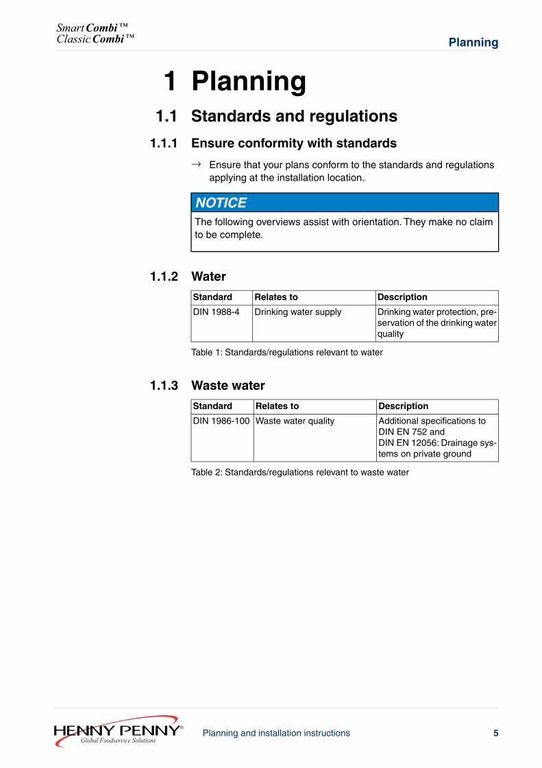
1.1.2 Water
DescriptionRelates toStandard
Drinking water protection, pre-servation of the drinking waterquality
Drinking water supplyDIN 1988-4
Table 1: Standards/regulations relevant to water
1.1.3 Waste water
DescriptionRelates toStandard
Additional specifications toDIN EN 752 andDIN EN 12056: Drainage sys-tems on private ground
Waste water qualityDIN 1986-100
Table 2: Standards/regulations relevant to waste water
5Planning and installation instructionsGlobal Foodservice Solutions
PlanningSmartCombi™ClassicCombi™
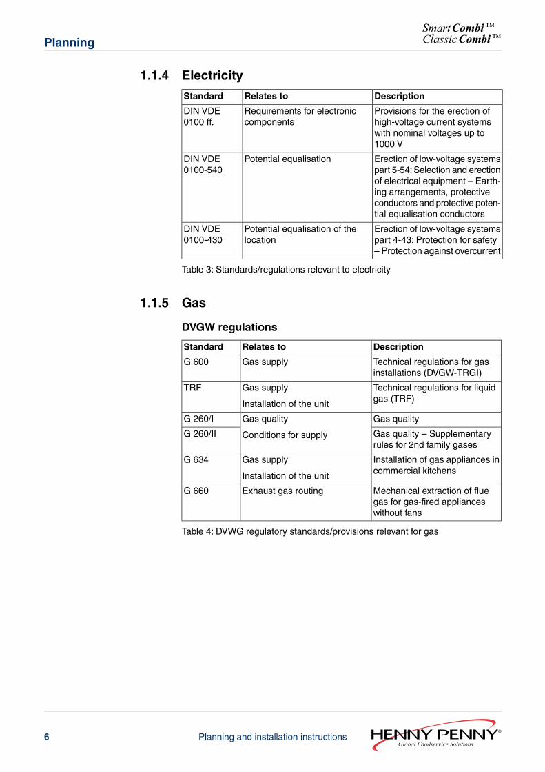
1.1.4 Electricity
DescriptionRelates toStandard
Provisions for the erection ofhigh-voltage current systemswith nominal voltages up to1000 V
Requirements for electroniccomponents
DIN VDE0100 ff.
Erection of low-voltage systemspart 5-54: Selection and erectionof electrical equipment – Earth-ing arrangements, protectiveconductors and protective poten-tial equalisation conductors
Potential equalisationDIN VDE0100-540
Erection of low-voltage systemspart 4-43: Protection for safety– Protection against overcurrent
Potential equalisation of thelocation
DIN VDE0100-430
Table 3: Standards/regulations relevant to electricity
1.1.5 Gas
DVGW regulations
DescriptionRelates toStandard
Technical regulations for gasinstallations (DVGW-TRGI)
Gas supplyG 600
Technical regulations for liquidgas (TRF)
Gas supply
Installation of the unit
TRF
Gas qualityGas quality
Conditions for supply
G 260/I
Gas quality – Supplementaryrules for 2nd family gases
G 260/II
Installation of gas appliances incommercial kitchens
Gas supply
Installation of the unit
G 634
Mechanical extraction of fluegas for gas-fired applianceswithout fans
Exhaust gas routingG 660
Table 4: DVWG regulatory standards/provisions relevant for gas
Global Foodservice SolutionsPlanning and installation instructions6
SmartCombi™ClassicCombi™Planning
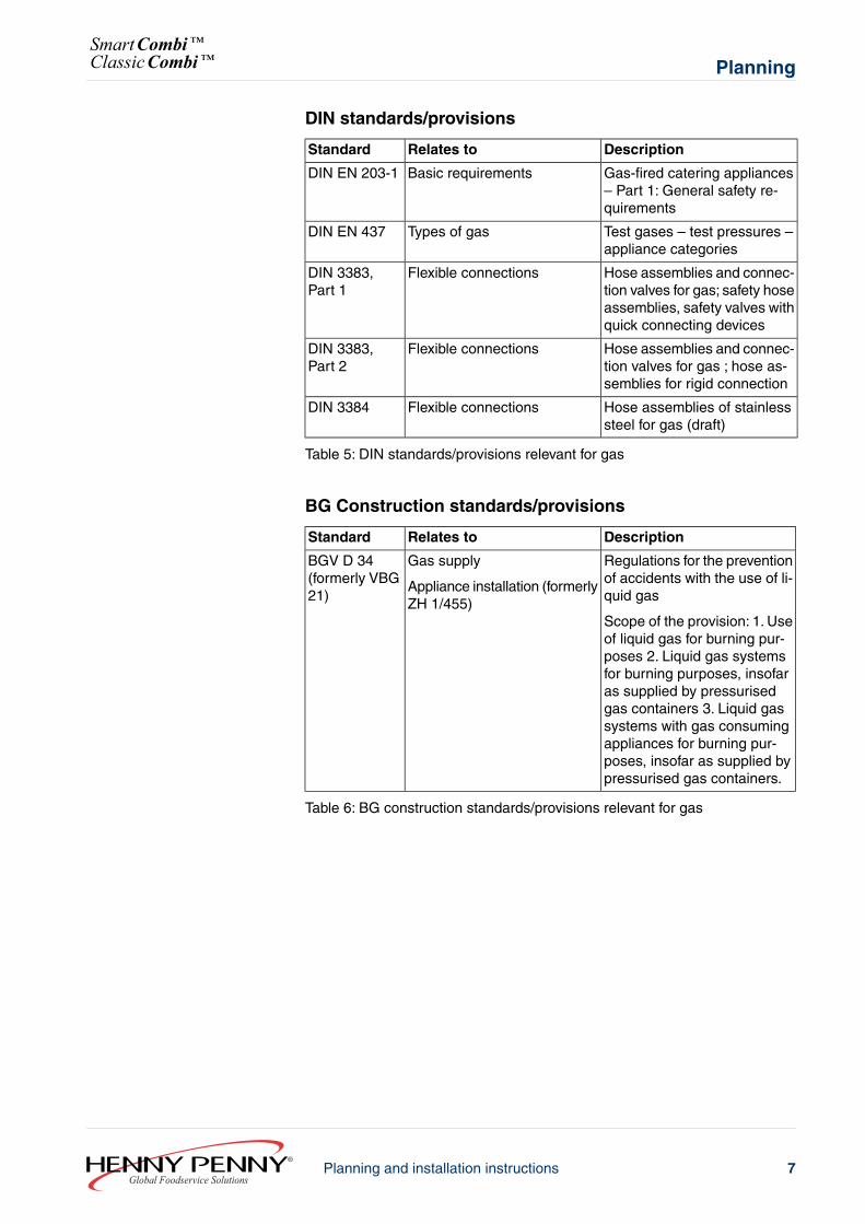
DIN standards/provisions
DescriptionRelates toStandard
Gas-fired catering appliances– Part 1: General safety re-quirements
Basic requirementsDIN EN 203-1
Test gases – test pressures –appliance categories
Types of gasDIN EN 437
Hose assemblies and connec-tion valves for gas; safety hoseassemblies, safety valves withquick connecting devices
Flexible connectionsDIN 3383,Part 1
Hose assemblies and connec-tion valves for gas ; hose as-semblies for rigid connection
Flexible connectionsDIN 3383,Part 2
Hose assemblies of stainlesssteel for gas (draft)
Flexible connectionsDIN 3384
Table 5: DIN standards/provisions relevant for gas
BG Construction standards/provisions
DescriptionRelates toStandard
Regulations for the preventionof accidents with the use of li-quid gas
Scope of the provision: 1. Useof liquid gas for burning pur-poses 2. Liquid gas systemsfor burning purposes, insofaras supplied by pressurisedgas containers 3. Liquid gassystems with gas consumingappliances for burning pur-poses, insofar as supplied bypressurised gas containers.
Gas supply
Appliance installation (formerlyZH 1/455)
BGV D 34(formerly VBG21)
Table 6: BG construction standards/provisions relevant for gas
7Planning and installation instructionsGlobal Foodservice Solutions
PlanningSmartCombi™ClassicCombi™
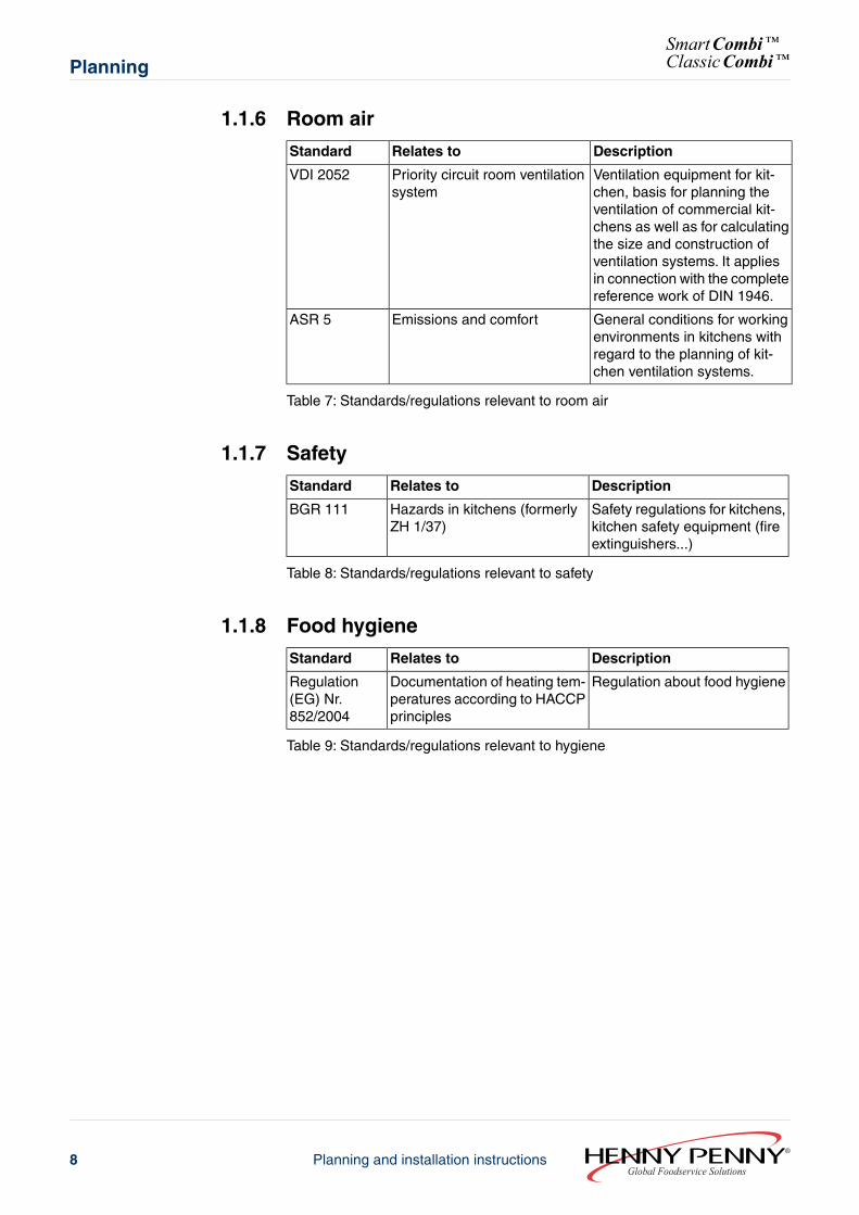
1.1.6 Room air
DescriptionRelates toStandard
Ventilation equipment for kit-chen, basis for planning theventilation of commercial kit-chens as well as for calculatingthe size and construction ofventilation systems. It appliesin connection with the completereference work of DIN 1946.
Priority circuit room ventilationsystem
VDI 2052
General conditions for workingenvironments in kitchens withregard to the planning of kit-chen ventilation systems.
Emissions and comfortASR 5
Table 7: Standards/regulations relevant to room air
1.1.7 Safety
DescriptionRelates toStandard
Safety regulations for kitchens,kitchen safety equipment (fireextinguishers...)
Hazards in kitchens (formerlyZH 1/37)
BGR 111
Table 8: Standards/regulations relevant to safety
1.1.8 Food hygiene
DescriptionRelates toStandard
Regulation about food hygieneDocumentation of heating tem-peratures according to HACCPprinciples
Regulation(EG) Nr.852/2004
Table 9: Standards/regulations relevant to hygiene
Global Foodservice SolutionsPlanning and installation instructions8
SmartCombi™ClassicCombi™Planning
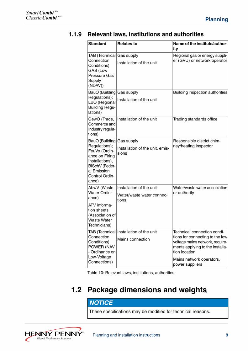
1.1.9 Relevant laws, institutions and authorities
Name of the institute/author-ity
Relates toStandard
Regional gas or energy suppli-er (GVU) or network operator
Gas supply
Installation of the unit
TAB (TechnicalConnectionConditions)GAS (LowPressure GasSupply(NDAV))
Building inspection authoritiesGas supply
Installation of the unit
BauO (BuildingRegulations);LBO (RegionalBuilding Regu-lations)
Trading standards officeInstallation of the unitGewO (Trade,Commerce andIndustry regula-tions)
Responsible district chim-ney/heating inspector
Gas supply
Installation of the unit, emis-sions
BauO (BuildingRegulations);FeuVo (Ordin-ance on FiringInstallations),BISchV (Feder-al EmissionControl Ordin-ance)
Water/waste water associationor authority
Installation of the unit
Water/waste water connec-tions
AbwV (WasteWater Ordin-ance)
ATV informa-tion sheets(Association ofWaste WaterTechnicians)
Technical connection condi-tions for connecting to the lowvoltage mains network, require-ments applying to the installa-tion location
Mains network operators,power suppliers
Installation of the unit
Mains connection
TAB (TechnicalConnectionConditions)POWER (NAV- Ordinance onLow-VoltageConnections)
Table 10: Relevant laws, institutions, authorities
1.2 Package dimensions and weights
NOTICEThese specifications may be modified for technical reasons.
9Planning and installation instructionsGlobal Foodservice Solutions
PlanningSmartCombi™ClassicCombi™
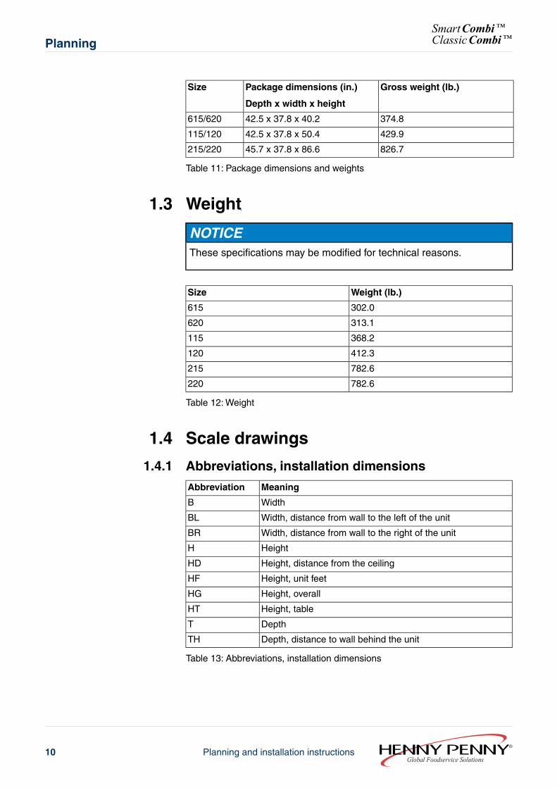
Gross weight (lb.)Package dimensions (in.)
Depth x width x height
Size
374.842.5 x 37.8 x 40.2615/620
429.942.5 x 37.8 x 50.4115/120
826.745.7 x 37.8 x 86.6215/220
Table 11: Package dimensions and weights
1.3 Weight
NOTICEThese specifications may be modified for technical reasons.
Weight (lb.)Size
302.0615
313.1620
368.2115
412.3120
782.6215
782.6220
Table 12: Weight
1.4 Scale drawings
1.4.1 Abbreviations, installation dimensions
MeaningAbbreviation
WidthB
Width, distance from wall to the left of the unitBL
Width, distance from wall to the right of the unitBR
HeightH
Height, distance from the ceilingHD
Height, unit feetHF
Height, overallHG
Height, tableHT
DepthT
Depth, distance to wall behind the unitTH
Table 13: Abbreviations, installation dimensions
Global Foodservice SolutionsPlanning and installation instructions10
SmartCombi™ClassicCombi™Planning
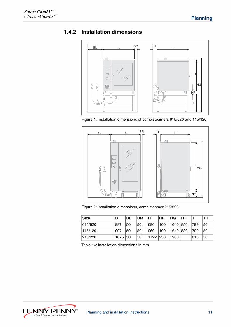
1.4.2 Installation dimensions
B BR TH
H
HG
HF
HT
BL T
Figure 1: Installation dimensions of combisteamers 615/620 and 115/120
B BR TH
HHG
HF
BL T
Figure 2: Installation dimensions, combisteamer 215/220
THTHTHGHFHBRBLBSize
5079985016401006905050997615/620
5079958016401009605050997115/120
50813 1960238172250501075215/220
Table 14: Installation dimensions in mm
11Planning and installation instructionsGlobal Foodservice Solutions
PlanningSmartCombi™ClassicCombi™
NOTICEA clearance of at least 50 mm from walls must be maintained to theright and the left of the unit as well as behind it.
A minimum distance of 500 mm to the left is recommended for servicing.
When using rack trolleys, the distance to the left of the unit should beat least 800 mm to allow the trolley to be positioned at the side.
Global Foodservice SolutionsPlanning and installation instructions12
SmartCombi™ClassicCombi™Planning
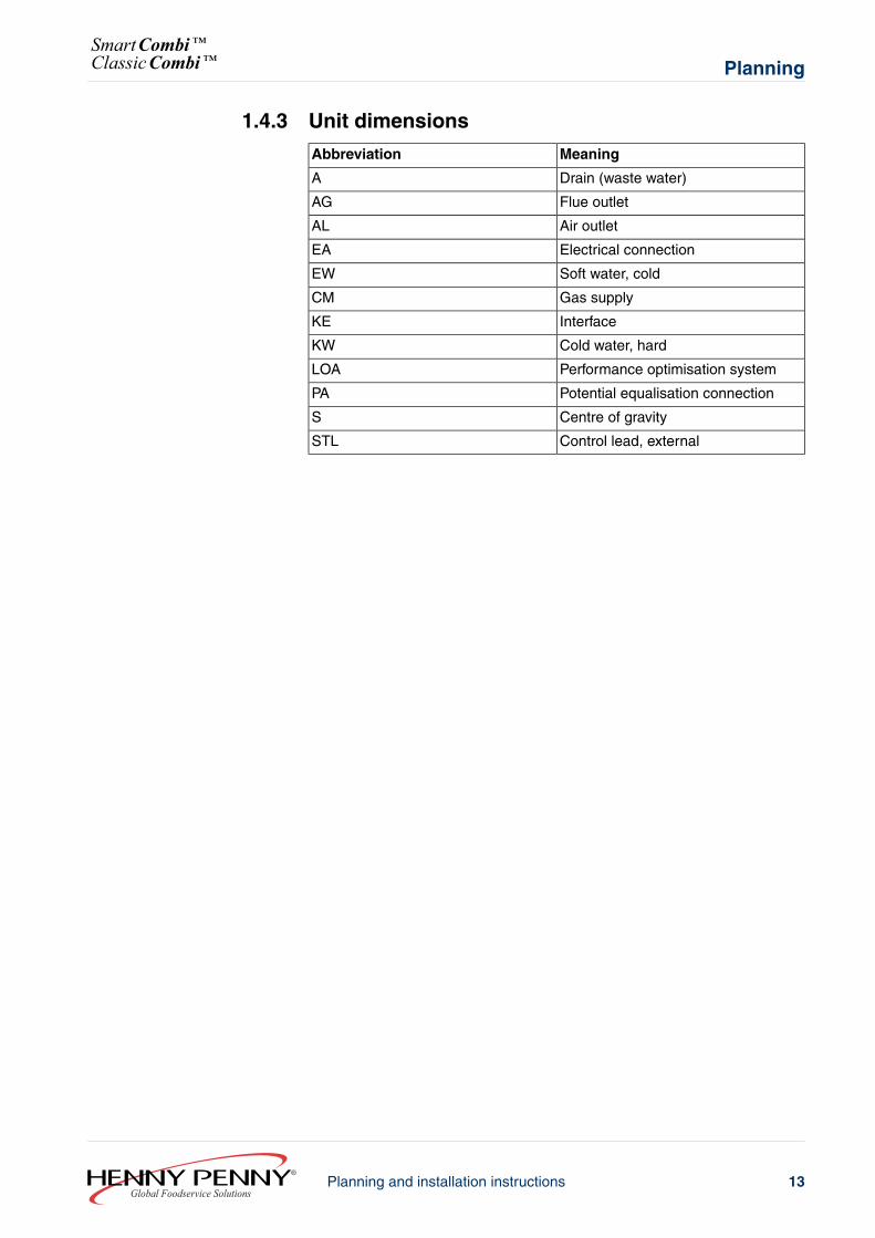
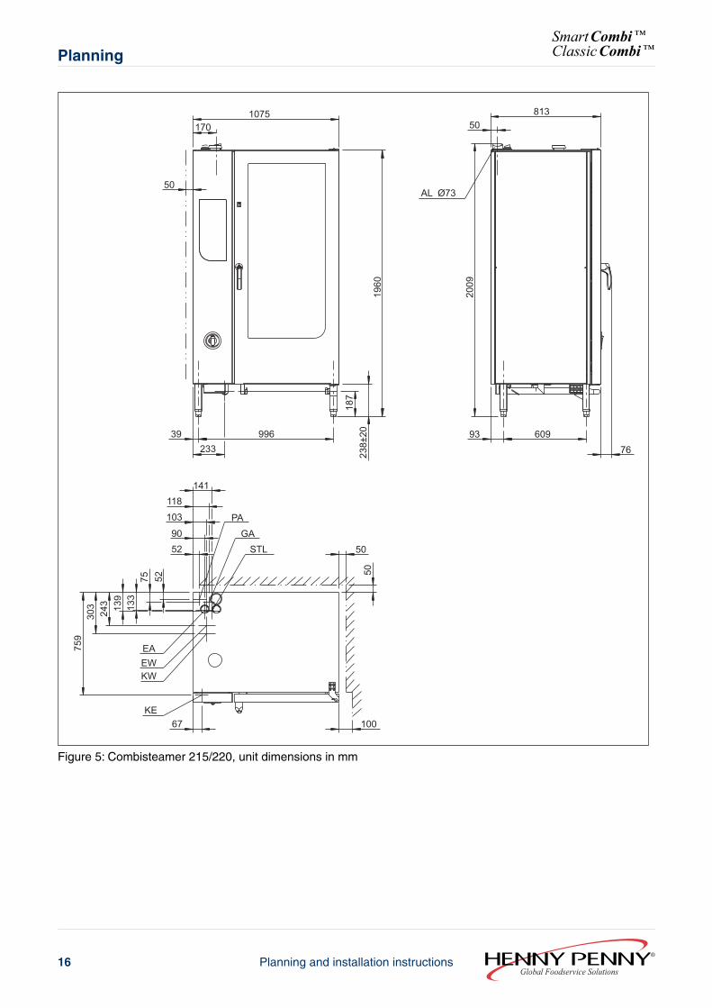
1.4.3 Unit dimensions
MeaningAbbreviation
Drain (waste water)A
Flue outletAG
Air outletAL
Electrical connectionEA
Soft water, coldEW
Gas supplyCM
InterfaceKE
Cold water, hardKW
Performance optimisation systemLOA
Potential equalisation connectionPA
Centre of gravityS
Control lead, externalSTL
13Planning and installation instructionsGlobal Foodservice Solutions
PlanningSmartCombi™ClassicCombi™
72
PA
EW
KW760
223
163
138 93
61 38
14097
7352
EAGA
STL 50
50
100
27873 897
A 5310
0+2
0 0
790
849
AL Ø5350
1651020
52799
100 535 76
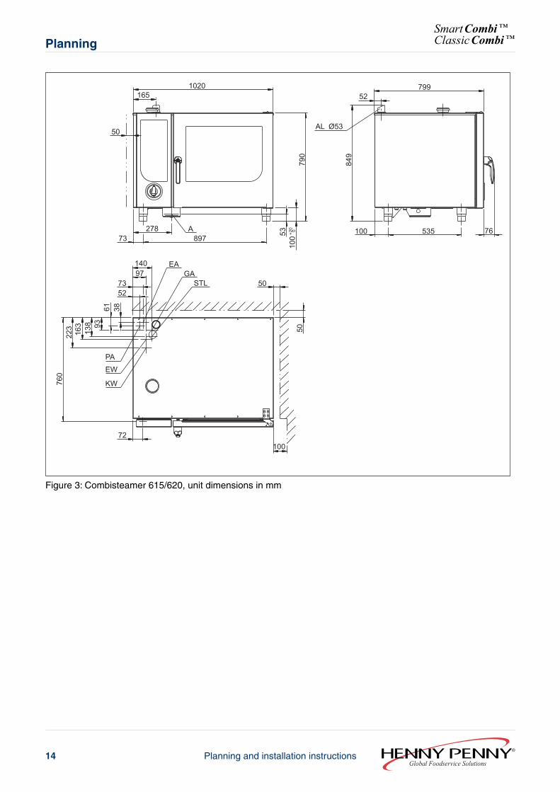
Figure 3: Combisteamer 615/620, unit dimensions in mm
Global Foodservice SolutionsPlanning and installation instructions14
SmartCombi™ClassicCombi™Planning
KE
140
71 100
977352
LOAEA
STL 50
50
73278
897 +20 0
100
PAEWKW
760
223
163
138 93
61 38
54
1060 1138
1020
AL Ø53
52799
100 535 76
50
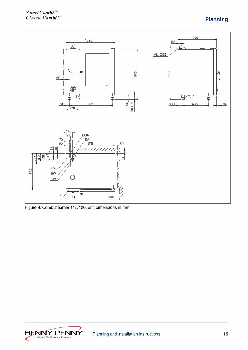
Figure 4: Combisteamer 115/120, unit dimensions in mm
15Planning and installation instructionsGlobal Foodservice Solutions
PlanningSmartCombi™ClassicCombi™
KE67
EAEWKW
759
303
243 13
913
375 52
141118103
9052
PA
GASTL 50
50
39233
996
187
238±
2019
60
2009
AL Ø7350
1701075
50813
93 60976
100
Figure 5: Combisteamer 215/220, unit dimensions in mm
Global Foodservice SolutionsPlanning and installation instructions16
SmartCombi™ClassicCombi™Planning
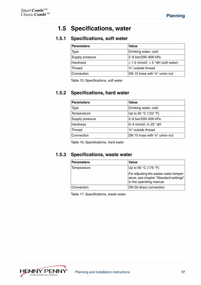
1.5 Specifications, water
1.5.1 Specifications, soft water
ValueParameters
Drinking water, coldType
2–6 bar/200–600 kPaSupply pressure
< 1.5 mmol/l, < 5 °dH (soft water)Hardness
¾" outside threadThread
DN 15 hose with ¾" union nutConnection
Table 15: Specifications, soft water
1.5.2 Specifications, hard water
ValueParameters
Drinking water, coldType
Up to 50 °C (122 °F)Temperature
2–6 bar/200–600 kPaSupply pressure
0–4 mmol/l, 0–25 °dHHardness
¾" outside threadThread
DN 15 hose with ¾" union nutConnection
Table 16: Specifications, hard water
1.5.3 Specifications, waste water
ValueParameters
Up to 80 °C (176 °F)
For adjusting the waster water temper-ature, see chapter “Standard settings”in the operating manual.
Temperature
DN 50 direct connectionConnection
Table 17: Specifications, waste water
17Planning and installation instructionsGlobal Foodservice Solutions
PlanningSmartCombi™ClassicCombi™
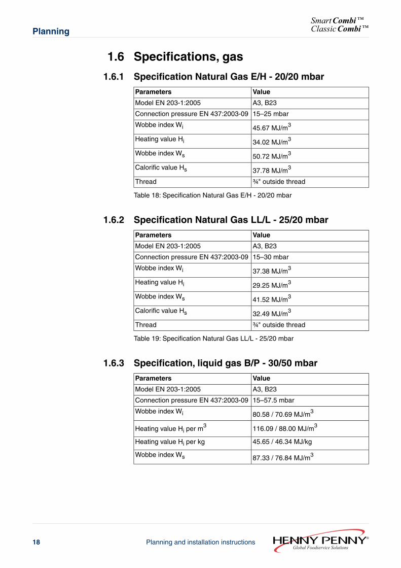
1.6 Specifications, gas
1.6.1 Specification Natural Gas E/H - 20/20 mbar
ValueParameters
A3, B23Model EN 203-1:2005
15–25 mbarConnection pressure EN 437:2003-09
45.67 MJ/m3Wobbe index Wi
34.02 MJ/m3Heating value Hi
50.72 MJ/m3Wobbe index Ws
37.78 MJ/m3Calorific value Hs
¾" outside threadThread
Table 18: Specification Natural Gas E/H - 20/20 mbar
1.6.2 Specification Natural Gas LL/L - 25/20 mbar
ValueParameters
A3, B23Model EN 203-1:2005
15–30 mbarConnection pressure EN 437:2003-09
37.38 MJ/m3Wobbe index Wi
29.25 MJ/m3Heating value Hi
41.52 MJ/m3Wobbe index Ws
32.49 MJ/m3Calorific value Hs
¾" outside threadThread
Table 19: Specification Natural Gas LL/L - 25/20 mbar
1.6.3 Specification, liquid gas B/P - 30/50 mbar
ValueParameters
A3, B23Model EN 203-1:2005
15–57.5 mbarConnection pressure EN 437:2003-09
80.58 / 70.69 MJ/m3Wobbe index Wi
116.09 / 88.00 MJ/m3Heating value Hi per m3
45.65 / 46.34 MJ/kgHeating value Hi per kg
87.33 / 76.84 MJ/m3Wobbe index Ws
Global Foodservice SolutionsPlanning and installation instructions18
SmartCombi™ClassicCombi™Planning
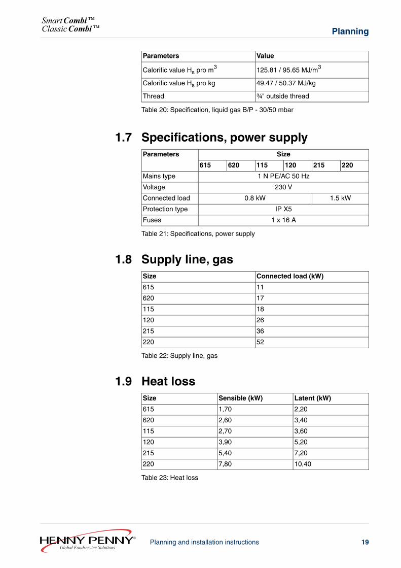
ValueParameters
125.81 / 95.65 MJ/m3Calorific value Hs pro m3
49.47 / 50.37 MJ/kgCalorific value Hs pro kg
¾" outside threadThread
Table 20: Specification, liquid gas B/P - 30/50 mbar
1.7 Specifications, power supplySizeParameters
220215120115620615
1 N PE/AC 50 HzMains type
230 VVoltage
1.5 kW0.8 kWConnected load
IP X5Protection type
1 x 16 AFuses
Table 21: Specifications, power supply
1.8 Supply line, gasConnected load (kW)Size
11615
17620
18115
26120
36215
52220
Table 22: Supply line, gas
1.9 Heat lossLatent (kW)Sensible (kW)Size
2,201,70615
3,402,60620
3,602,70115
5,203,90120
7,205,40215
10,407,80220
Table 23: Heat loss
19Planning and installation instructionsGlobal Foodservice Solutions
PlanningSmartCombi™ClassicCombi™
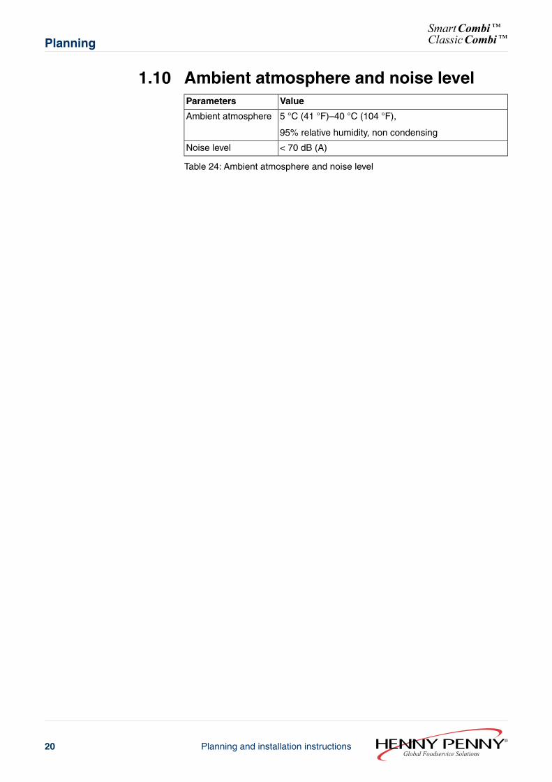
1.10 Ambient atmosphere and noise levelValueParameters
5 °C (41 °F)–40 °C (104 °F),
95% relative humidity, non condensing
Ambient atmosphere
< 70 dB (A)Noise level
Table 24: Ambient atmosphere and noise level
Global Foodservice SolutionsPlanning and installation instructions20
SmartCombi™ClassicCombi™Planning
2 Transport2.1 Transporting the unit
L
H
B
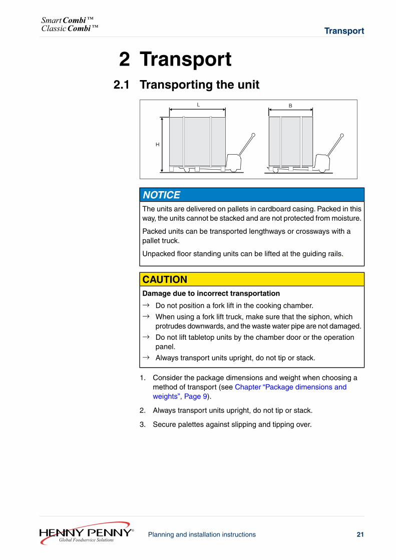
NOTICEThe units are delivered on pallets in cardboard casing. Packed in thisway, the units cannot be stacked and are not protected from moisture.
Packed units can be transported lengthways or crossways with apallet truck.
Unpacked floor standing units can be lifted at the guiding rails.
CAUTIONDamage due to incorrect transportation
→ Do not position a fork lift in the cooking chamber.→ When using a fork lift truck, make sure that the siphon, which
protrudes downwards, and the waste water pipe are not damaged.→ Do not lift tabletop units by the chamber door or the operation
panel.→ Always transport units upright, do not tip or stack.
1. Consider the package dimensions and weight when choosing amethod of transport (see Chapter “Package dimensions andweights”, Page 9).
2. Always transport units upright, do not tip or stack.
3. Secure palettes against slipping and tipping over.
21Planning and installation instructionsGlobal Foodservice Solutions
TransportSmartCombi™ClassicCombi™
3 Installation3.1 Installation information
Before installing NOTICEExamine the unit for transportation damage. Do not install or usedamaged units.
Remove the protective film from the external panels before using forthe first time.
Remove foam transport protection from the chamber.
Fire prevention regulations NOTICEObserve the local fire prevention regulations when installing near tomaterials that are heat sensitive or endangered by fire.
Covers on top of the unit must be fire-proof.
Units may only be installed on or against fire-proof surfaces and incompliance with fire prevention regulations.
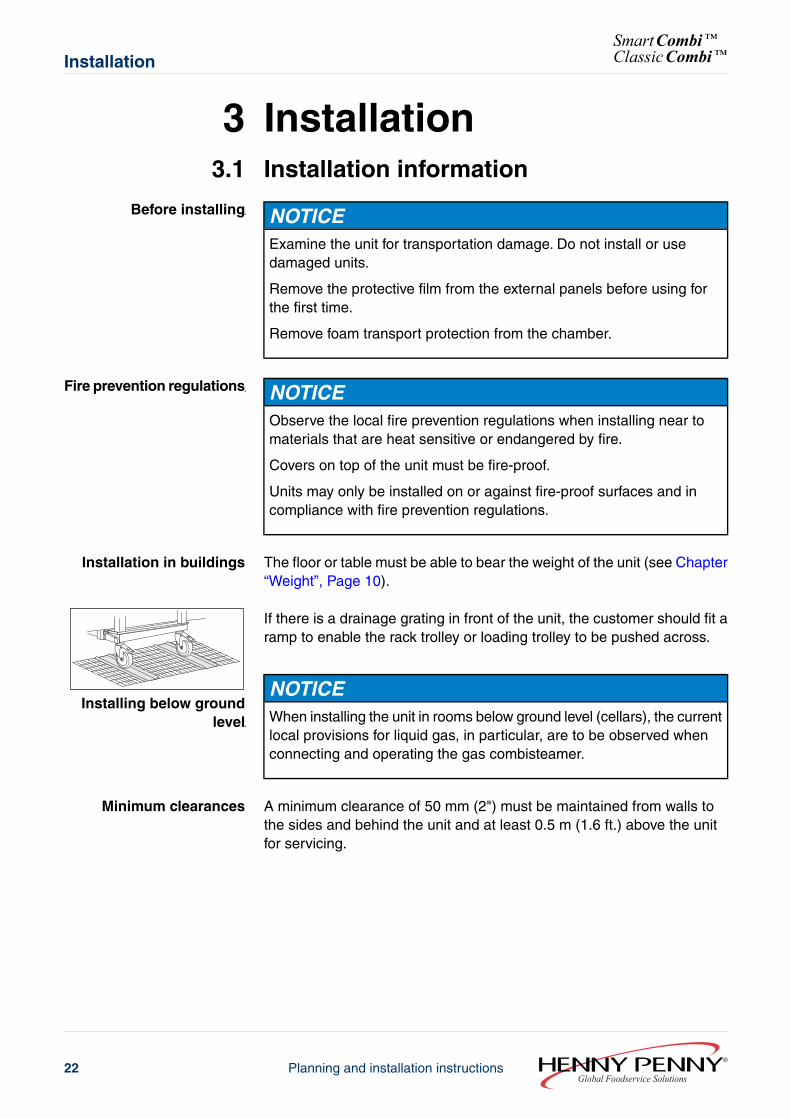
Installation in buildings The floor or table must be able to bear the weight of the unit (see Chapter“Weight”, Page 10).
If there is a drainage grating in front of the unit, the customer should fit aramp to enable the rack trolley or loading trolley to be pushed across.
Installing below groundlevel
NOTICEWhen installing the unit in rooms below ground level (cellars), the currentlocal provisions for liquid gas, in particular, are to be observed whenconnecting and operating the gas combisteamer.
Minimum clearances A minimum clearance of 50 mm (2") must be maintained from walls tothe sides and behind the unit and at least 0.5 m (1.6 ft.) above the unitfor servicing.
Global Foodservice SolutionsPlanning and installation instructions22
SmartCombi™ClassicCombi™Installation
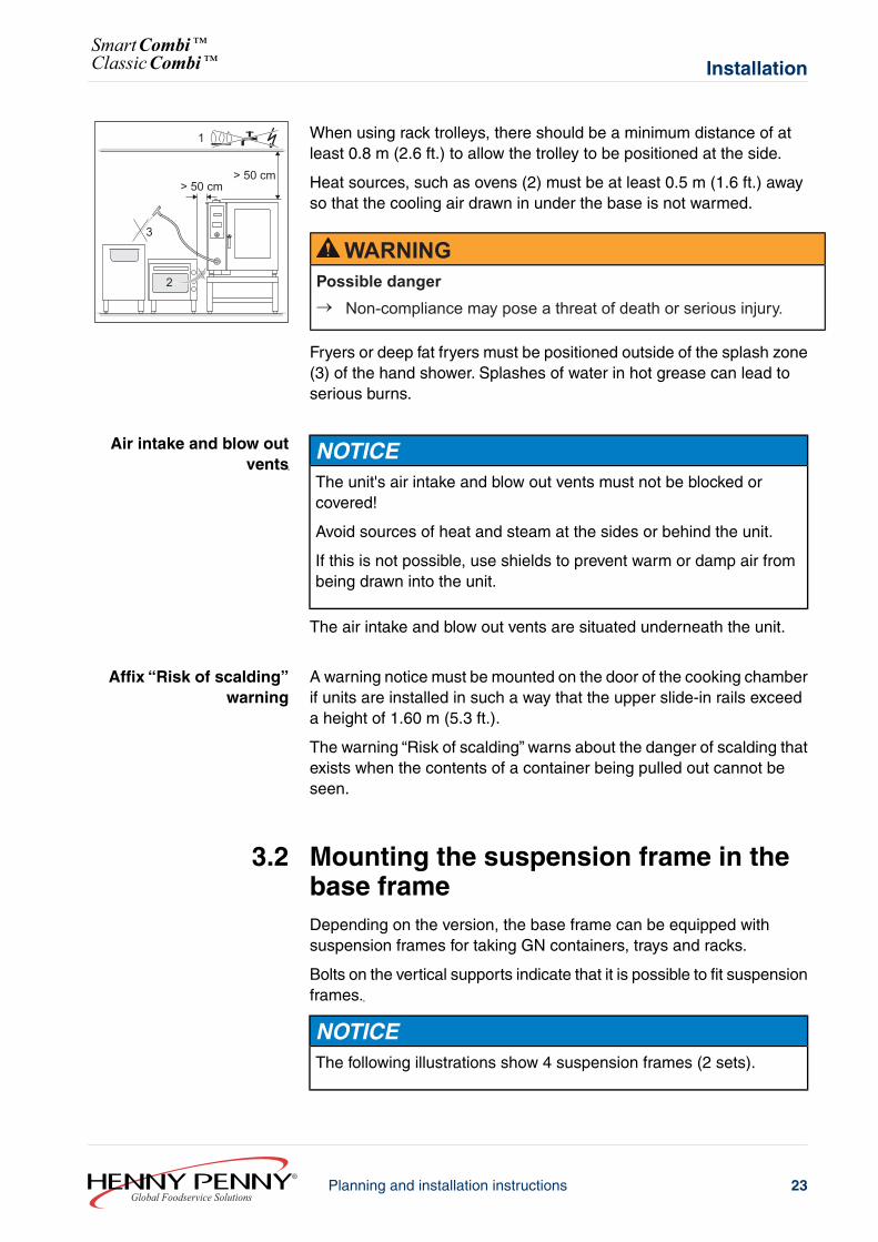
When using rack trolleys, there should be a minimum distance of atleast 0.8 m (2.6 ft.) to allow the trolley to be positioned at the side.
Heat sources, such as ovens (2) must be at least 0.5 m (1.6 ft.) awayso that the cooling air drawn in under the base is not warmed.
WARNINGPossible danger→ Non-compliance may pose a threat of death or serious injury.
Fryers or deep fat fryers must be positioned outside of the splash zone(3) of the hand shower. Splashes of water in hot grease can lead toserious burns.
Air intake and blow outvents
NOTICEThe unit's air intake and blow out vents must not be blocked orcovered!
Avoid sources of heat and steam at the sides or behind the unit.
If this is not possible, use shields to prevent warm or damp air frombeing drawn into the unit.
The air intake and blow out vents are situated underneath the unit.
Affix “Risk of scalding”warning
A warning notice must be mounted on the door of the cooking chamberif units are installed in such a way that the upper slide-in rails exceeda height of 1.60 m (5.3 ft.).
The warning “Risk of scalding” warns about the danger of scalding thatexists when the contents of a container being pulled out cannot beseen.
3.2 Mounting the suspension frame in thebase frameDepending on the version, the base frame can be equipped withsuspension frames for taking GN containers, trays and racks.
Bolts on the vertical supports indicate that it is possible to fit suspensionframes.
NOTICEThe following illustrations show 4 suspension frames (2 sets).
23Planning and installation instructionsGlobal Foodservice Solutions
InstallationSmartCombi™ClassicCombi™
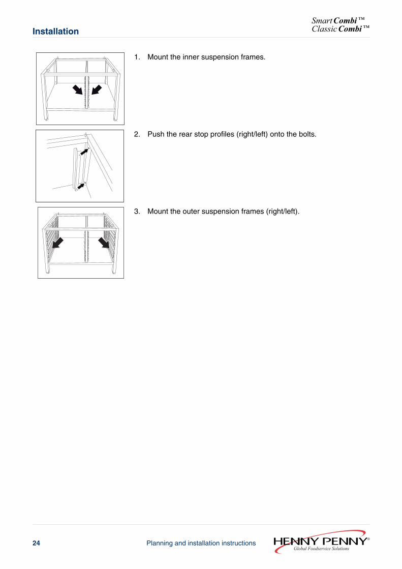
1. Mount the inner suspension frames.
2. Push the rear stop profiles (right/left) onto the bolts.
3. Mount the outer suspension frames (right/left).
Global Foodservice SolutionsPlanning and installation instructions24
SmartCombi™ClassicCombi™Installation
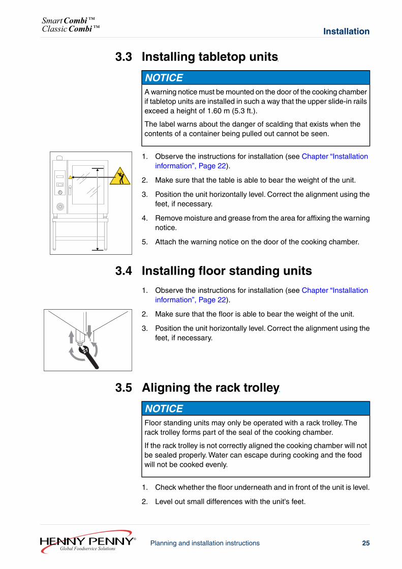
3.3 Installing tabletop units
NOTICEA warning notice must be mounted on the door of the cooking chamberif tabletop units are installed in such a way that the upper slide-in railsexceed a height of 1.60 m (5.3 ft.).
The label warns about the danger of scalding that exists when thecontents of a container being pulled out cannot be seen.
1. Observe the instructions for installation (see Chapter “Installationinformation”, Page 22).
2. Make sure that the table is able to bear the weight of the unit.
3. Position the unit horizontally level. Correct the alignment using thefeet, if necessary.
4. Remove moisture and grease from the area for affixing the warningnotice.
5. Attach the warning notice on the door of the cooking chamber.
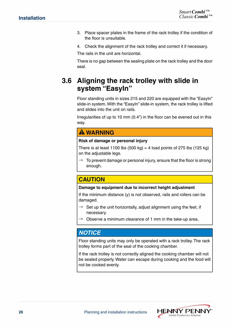
3.4 Installing floor standing units1. Observe the instructions for installation (see Chapter “Installation
information”, Page 22).
2. Make sure that the floor is able to bear the weight of the unit.
3. Position the unit horizontally level. Correct the alignment using thefeet, if necessary.
3.5 Aligning the rack trolley
NOTICEFloor standing units may only be operated with a rack trolley. Therack trolley forms part of the seal of the cooking chamber.
If the rack trolley is not correctly aligned the cooking chamber will notbe sealed properly. Water can escape during cooking and the foodwill not be cooked evenly.
1. Check whether the floor underneath and in front of the unit is level.
2. Level out small differences with the unit's feet.
25Planning and installation instructionsGlobal Foodservice Solutions
InstallationSmartCombi™ClassicCombi™
3. Place spacer plates in the frame of the rack trolley if the condition ofthe floor is unsuitable.
4. Check the alignment of the rack trolley and correct it if necessary.
The rails in the unit are horizontal.
There is no gap between the sealing plate on the rack trolley and the doorseal.
3.6 Aligning the rack trolley with slide insystem “EasyIn”Floor standing units in sizes 215 and 220 are equipped with the “EasyIn”slide-in system. With the “EasyIn” slide-in system, the rack trolley is liftedand slides into the unit on rails.
Irregularities of up to 10 mm (0.4") in the floor can be evened out in thisway.
WARNINGRisk of damage or personal injury
There is at least 1100 lbs (500 kg) = 4 load points of 275 lbs (125 kg)on the adjustable legs.
→ To prevent damage or personal injury, ensure that the floor is strongenough.
CAUTIONDamage to equipment due to incorrect height adjustment
If the minimum distance (y) is not observed, rails and rollers can bedamaged.
→ Set up the unit horizontally, adjust alignment using the feet, ifnecessary.
→ Observe a minimum clearance of 1 mm in the take-up area.
NOTICEFloor standing units may only be operated with a rack trolley. The racktrolley forms part of the seal of the cooking chamber.
If the rack trolley is not correctly aligned the cooking chamber will notbe sealed properly. Water can escape during cooking and the food willnot be cooked evenly.
Global Foodservice SolutionsPlanning and installation instructions26
SmartCombi™ClassicCombi™Installation
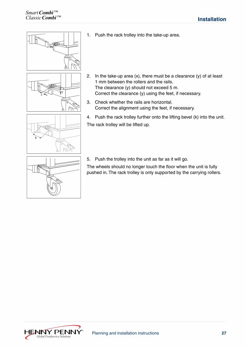
1. Push the rack trolley into the take-up area.
xy
2. In the take-up area (x), there must be a clearance (y) of at least1 mm between the rollers and the rails.The clearance (y) should not exceed 5 m.Correct the clearance (y) using the feet, if necessary.
3. Check whether the rails are horizontal.Correct the alignment using the feet, if necessary.
k
4. Push the rack trolley further onto the lifting bevel (k) into the unit.
The rack trolley will be lifted up.
5. Push the trolley into the unit as far as it will go.
The wheels should no longer touch the floor when the unit is fullypushed in. The rack trolley is only supported by the carrying rollers.
27Planning and installation instructionsGlobal Foodservice Solutions
InstallationSmartCombi™ClassicCombi™
4 Electricity4.1 Power cable requirements
LK
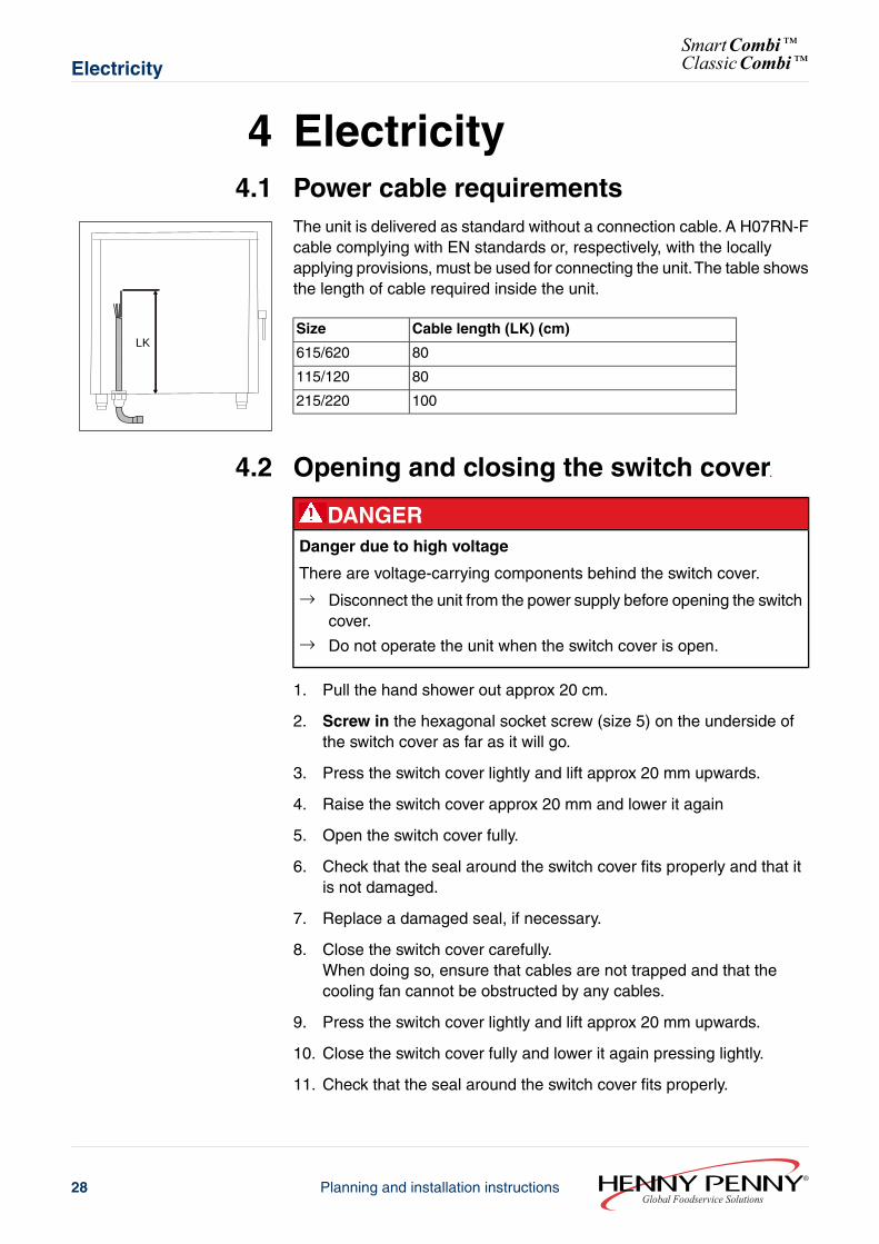
The unit is delivered as standard without a connection cable. A H07RN-Fcable complying with EN standards or, respectively, with the locallyapplying provisions, must be used for connecting the unit.The table showsthe length of cable required inside the unit.
Cable length (LK) (cm)Size
80615/620
80115/120
100215/220
4.2 Opening and closing the switch cover
DANGERDanger due to high voltage
There are voltage-carrying components behind the switch cover.
→ Disconnect the unit from the power supply before opening the switchcover.
→ Do not operate the unit when the switch cover is open.
1. Pull the hand shower out approx 20 cm.
2. Screw in the hexagonal socket screw (size 5) on the underside ofthe switch cover as far as it will go.
3. Press the switch cover lightly and lift approx 20 mm upwards.
4. Raise the switch cover approx 20 mm and lower it again
5. Open the switch cover fully.
6. Check that the seal around the switch cover fits properly and that itis not damaged.
7. Replace a damaged seal, if necessary.
8. Close the switch cover carefully.When doing so, ensure that cables are not trapped and that thecooling fan cannot be obstructed by any cables.
9. Press the switch cover lightly and lift approx 20 mm upwards.
10. Close the switch cover fully and lower it again pressing lightly.
11. Check that the seal around the switch cover fits properly.
Global Foodservice SolutionsPlanning and installation instructions28
SmartCombi™ClassicCombi™Electricity
12. If necessary, open the switch cover and correct the position of theseal.
13. Screw out the hexagonal socket screw (size 5) on the undersideof the switch cover.
4.3 Description of the terminal strip
A1/X5.11A1/X5.12
K1/A2
X3PE
PEPE
13N
1112
12
34
A_TXD+B_TXD-
B_RXD-A_RXD+ YE
GNBNWH
H13/A1
R = 150 Ω
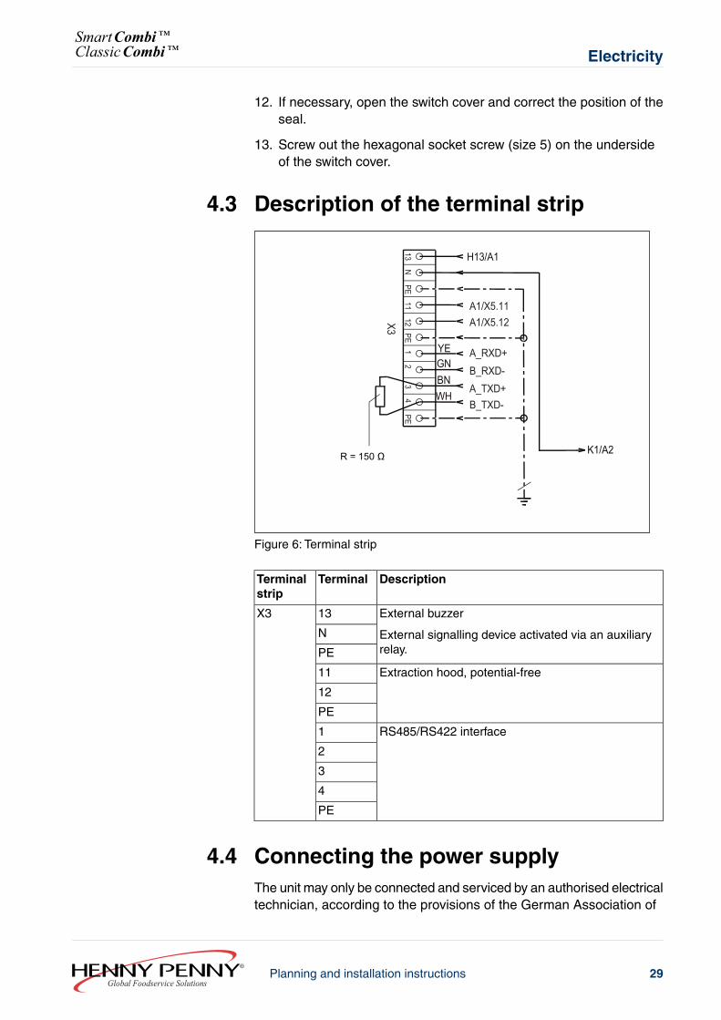
Figure 6: Terminal strip
DescriptionTerminalTerminalstrip
External buzzer
External signalling device activated via an auxiliaryrelay.
13X3
N
PE
Extraction hood, potential-free11
12
PE
RS485/RS422 interface1
2
3
4
PE
4.4 Connecting the power supplyThe unit may only be connected and serviced by an authorised electricaltechnician, according to the provisions of the German Association of
29Planning and installation instructionsGlobal Foodservice Solutions
ElectricitySmartCombi™ClassicCombi™
Electrical Technicians, the power supply company and the informationon the nameplate.
Have damaged power cables replaced by customer service to avoid risksof damage or injury.
The connection can be made either with a plug or by connecting directly.
Isolator with direct connections
The power supply must be fitted with an all pole isolator (e.g. automaticcutout) with a minimum contact opening of 3 mm, so that the unit can beremoved from the mains at any time.
Plug connection
The plug socket must be adequately protected.
Potential equalisation
The unit can be included in a potential equalisation system (grounding).The connection terminal is underneath the information plate.
1. Prepare the connection cable (see Chapter “Power cablerequirements”, Page 28).
2. Remove the left side panel.
3. Pass the connection cable through the strain relief screws into theunit.
4. Connect the connection cable with the connecting terminals accordingto the connection diagram.
5. Sizes 115 and 120: Secure the connection cable additionally withcable clips.
6. Secure the left side panel.
4.5 RS485/RS422 interfaceSmartCombi units are equipped as standard with a four-pin RS485interface; this is optional with ClassicCombi.The interface can be reducedto a two-pin RS422 interface.
1. Bridge the terminals to reduce the interface to a two-pole RS422interface.- X3/1 to X3/3- X3/2 to X3/4
2. Use twisted wires (e. g. LiYY (TP) 2x2x0.5) for the connection.
3. Close the last unit with a 150 Ω terminating bus resistor.
Global Foodservice SolutionsPlanning and installation instructions30
SmartCombi™ClassicCombi™Electricity
5 Water5.1 Water supply
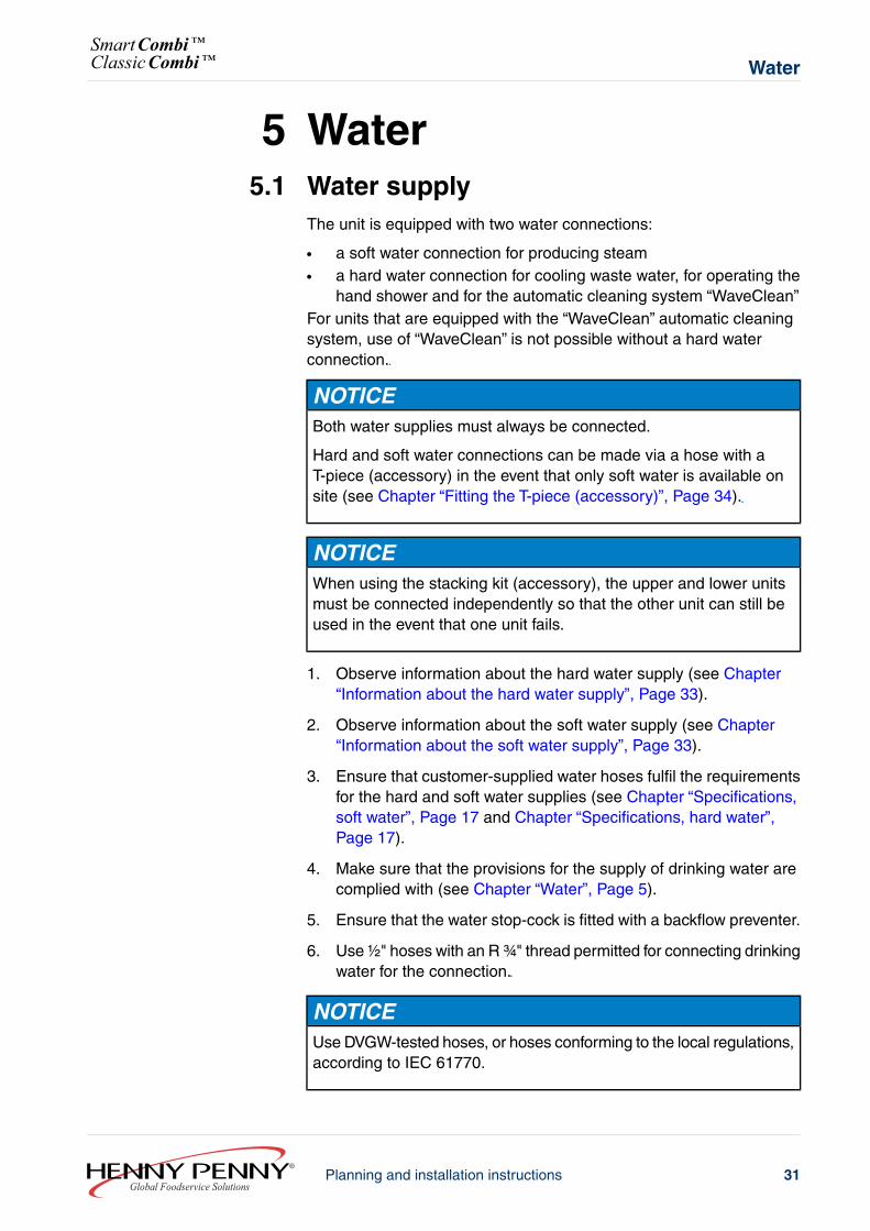
The unit is equipped with two water connections:
● a soft water connection for producing steam● a hard water connection for cooling waste water, for operating the
hand shower and for the automatic cleaning system “WaveClean”For units that are equipped with the “WaveClean” automatic cleaningsystem, use of “WaveClean” is not possible without a hard waterconnection.
NOTICEBoth water supplies must always be connected.
Hard and soft water connections can be made via a hose with aT-piece (accessory) in the event that only soft water is available onsite (see Chapter “Fitting the T-piece (accessory)”, Page 34).
NOTICEWhen using the stacking kit (accessory), the upper and lower unitsmust be connected independently so that the other unit can still beused in the event that one unit fails.
1. Observe information about the hard water supply (see Chapter“Information about the hard water supply”, Page 33).
2. Observe information about the soft water supply (see Chapter“Information about the soft water supply”, Page 33).
3. Ensure that customer-supplied water hoses fulfil the requirementsfor the hard and soft water supplies (see Chapter “Specifications,soft water”, Page 17 and Chapter “Specifications, hard water”,Page 17).
4. Make sure that the provisions for the supply of drinking water arecomplied with (see Chapter “Water”, Page 5).
5. Ensure that the water stop-cock is fitted with a backflow preventer.
6. Use ½" hoses with an R ¾" thread permitted for connecting drinkingwater for the connection.
NOTICEUse DVGW-tested hoses, or hoses conforming to the local regulations,according to IEC 61770.
31Planning and installation instructionsGlobal Foodservice Solutions
WaterSmartCombi™ClassicCombi™
7. When preparing the hoses, calculate the length to allow 0.8 m to bepulled out from the unit after connection, for later servicing.
8. Rinse out customer-supplied hoses for the hard and soft waterconnections.
9. Make sure that the filters fitted as standard to the unit's water inletsare present.
CAUTIONDamages caused by incorrect water supply
→ Do not confuse the hard water and the soft water connections.
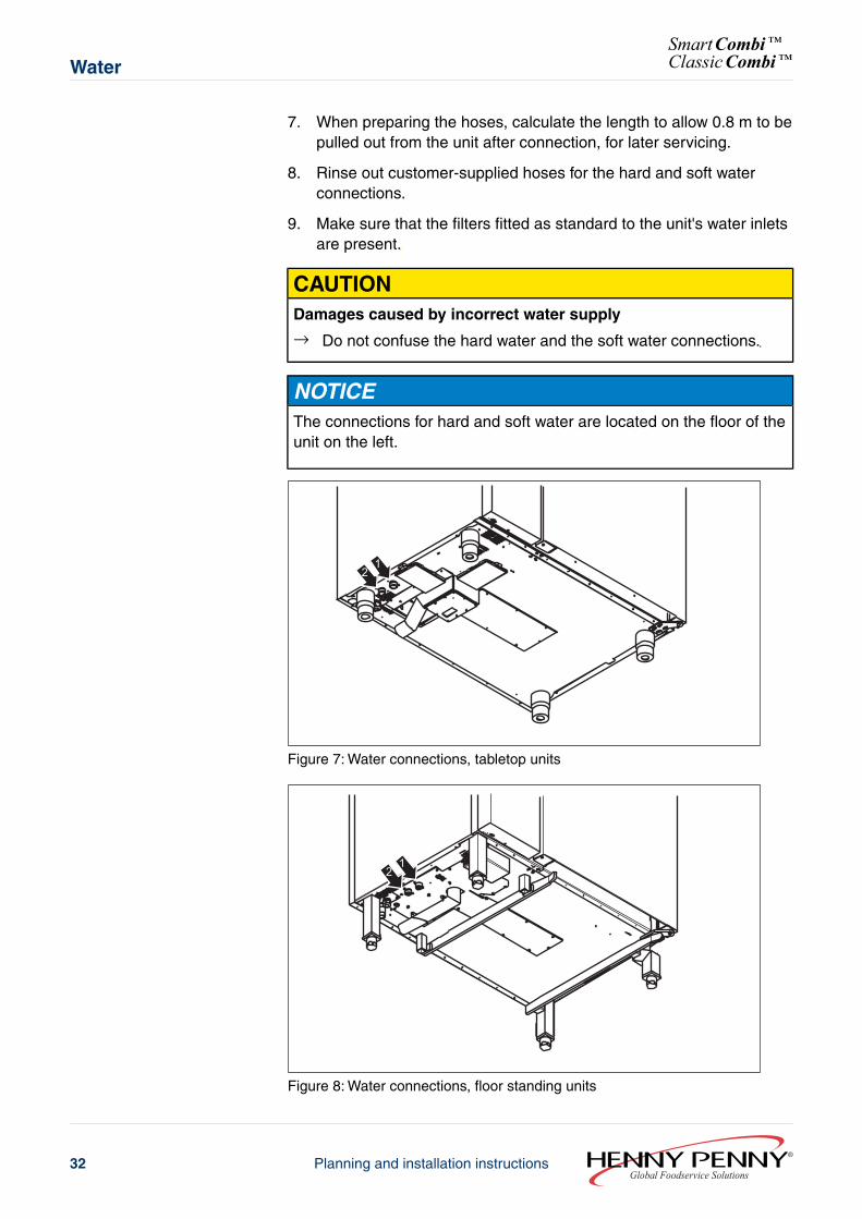
NOTICEThe connections for hard and soft water are located on the floor of theunit on the left.
21
Figure 7: Water connections, tabletop units
12
Figure 8: Water connections, floor standing units
Global Foodservice SolutionsPlanning and installation instructions32
SmartCombi™ClassicCombi™Water
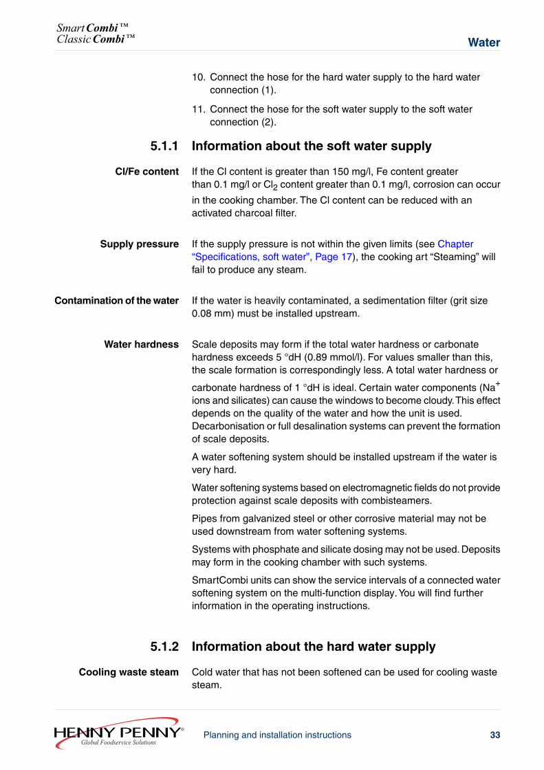
10. Connect the hose for the hard water supply to the hard waterconnection (1).
11. Connect the hose for the soft water supply to the soft waterconnection (2).
5.1.1 Information about the soft water supply
Cl/Fe content If the Cl content is greater than 150 mg/l, Fe content greaterthan 0.1 mg/l or Cl2 content greater than 0.1 mg/l, corrosion can occur
in the cooking chamber. The Cl content can be reduced with anactivated charcoal filter.
Supply pressure If the supply pressure is not within the given limits (see Chapter“Specifications, soft water”, Page 17), the cooking art “Steaming” willfail to produce any steam.
Contamination of the water If the water is heavily contaminated, a sedimentation filter (grit size0.08 mm) must be installed upstream.
Water hardness Scale deposits may form if the total water hardness or carbonatehardness exceeds 5 °dH (0.89 mmol/l). For values smaller than this,the scale formation is correspondingly less. A total water hardness or
carbonate hardness of 1 °dH is ideal. Certain water components (Na+
ions and silicates) can cause the windows to become cloudy.This effectdepends on the quality of the water and how the unit is used.Decarbonisation or full desalination systems can prevent the formationof scale deposits.
A water softening system should be installed upstream if the water isvery hard.
Water softening systems based on electromagnetic fields do not provideprotection against scale deposits with combisteamers.
Pipes from galvanized steel or other corrosive material may not beused downstream from water softening systems.
Systems with phosphate and silicate dosing may not be used. Depositsmay form in the cooking chamber with such systems.
SmartCombi units can show the service intervals of a connected watersoftening system on the multi-function display.You will find furtherinformation in the operating instructions.
5.1.2 Information about the hard water supply
Cooling waste steam Cold water that has not been softened can be used for cooling wastesteam.
33Planning and installation instructionsGlobal Foodservice Solutions
WaterSmartCombi™ClassicCombi™
Warm water leads to increased water consumption and should not beused.
The water temperature must not exceed 50 °C (122 °F).
Automatic cleaning system“WaveClean”
Units that are equipped with the “WaveClean” automatic cleaning systemmust always be connected to a hard water and a soft water supply.
Otherwise, cleaning with “WaveClean” is not possible.
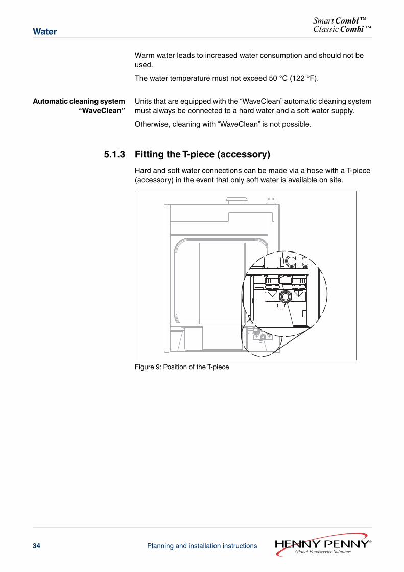
5.1.3 Fitting the T-piece (accessory)
Hard and soft water connections can be made via a hose with a T-piece(accessory) in the event that only soft water is available on site.
Figure 9: Position of the T-piece
Global Foodservice SolutionsPlanning and installation instructions34
SmartCombi™ClassicCombi™Water
1
2
3
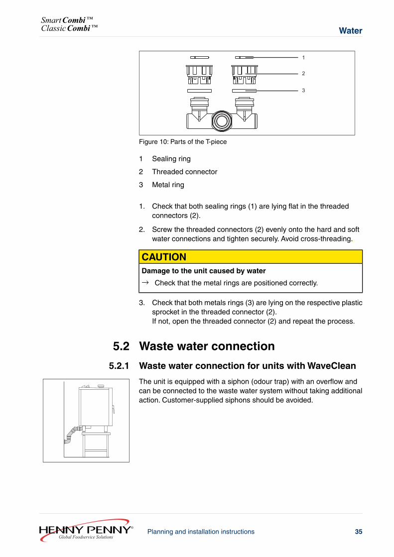
Figure 10: Parts of the T-piece
1 Sealing ring
2 Threaded connector
3 Metal ring
1. Check that both sealing rings (1) are lying flat in the threadedconnectors (2).
2. Screw the threaded connectors (2) evenly onto the hard and softwater connections and tighten securely. Avoid cross-threading.
CAUTIONDamage to the unit caused by water
→ Check that the metal rings are positioned correctly.
3. Check that both metals rings (3) are lying on the respective plasticsprocket in the threaded connector (2).If not, open the threaded connector (2) and repeat the process.
5.2 Waste water connection
5.2.1 Waste water connection for units with WaveClean
The unit is equipped with a siphon (odour trap) with an overflow andcan be connected to the waste water system without taking additionalaction. Customer-supplied siphons should be avoided.
35Planning and installation instructionsGlobal Foodservice Solutions
WaterSmartCombi™ClassicCombi™
1
2
3
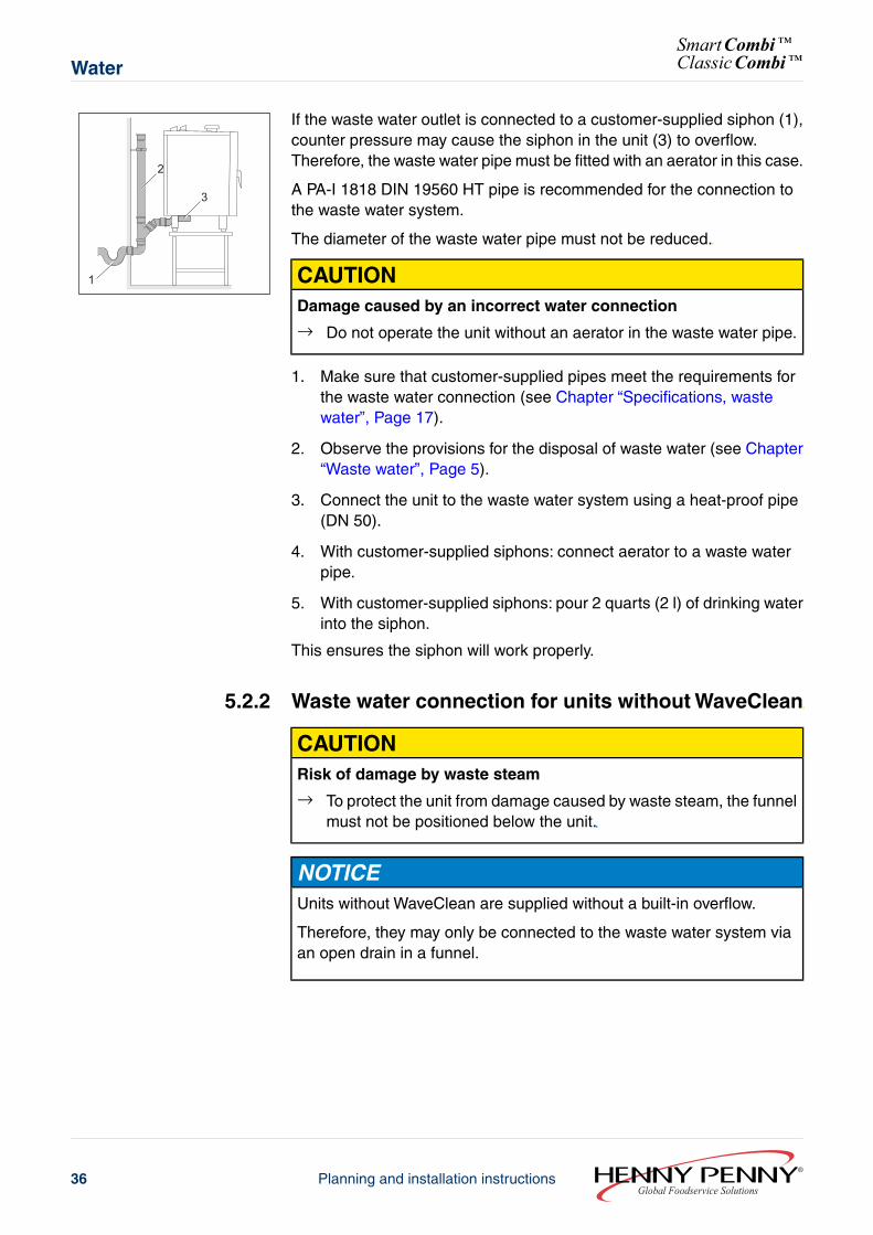
If the waste water outlet is connected to a customer-supplied siphon (1),counter pressure may cause the siphon in the unit (3) to overflow.Therefore, the waste water pipe must be fitted with an aerator in this case.
A PA-I 1818 DIN 19560 HT pipe is recommended for the connection tothe waste water system.
The diameter of the waste water pipe must not be reduced.
CAUTIONDamage caused by an incorrect water connection
→ Do not operate the unit without an aerator in the waste water pipe.
1. Make sure that customer-supplied pipes meet the requirements forthe waste water connection (see Chapter “Specifications, wastewater”, Page 17).
2. Observe the provisions for the disposal of waste water (see Chapter“Waste water”, Page 5).
3. Connect the unit to the waste water system using a heat-proof pipe(DN 50).
4. With customer-supplied siphons: connect aerator to a waste waterpipe.
5. With customer-supplied siphons: pour 2 quarts (2 l) of drinking waterinto the siphon.
This ensures the siphon will work properly.
5.2.2 Waste water connection for units without WaveClean
CAUTIONRisk of damage by waste steam
→ To protect the unit from damage caused by waste steam, the funnelmust not be positioned below the unit.
NOTICEUnits without WaveClean are supplied without a built-in overflow.
Therefore, they may only be connected to the waste water system viaan open drain in a funnel.
Global Foodservice SolutionsPlanning and installation instructions36
SmartCombi™ClassicCombi™Water
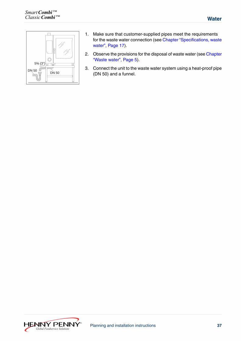
DN 50DN 50
5% (3°)
1. Make sure that customer-supplied pipes meet the requirementsfor the waste water connection (see Chapter “Specifications, wastewater”, Page 17).
2. Observe the provisions for the disposal of waste water (see Chapter“Waste water”, Page 5).
3. Connect the unit to the waste water system using a heat-proof pipe(DN 50) and a funnel.
37Planning and installation instructionsGlobal Foodservice Solutions
WaterSmartCombi™ClassicCombi™
6 Gas6.1 Gas supply
Requirements The following conditions must be met before the gas pipeline is connectedto the unit:
● All gas connection parts (also those supplied by the customer) mustbe tested according to DIN-DVGW (German Association for Gas andWater).
● The central gas supply must not be located within the safety distancesand must be freely accessible.
● The supply pipeline must have a diameter of at least ¾“.
WARNINGRisk of fire
Unintended moving of the appliance results in damage to gas line andpossible fire.
→ Do not equip this appliance with casters or with stands with casters.→ Do not equip this appliance with stands with casters.
CAUTIONMaterial damage due to insuffient aeration
The amount of fresh air needed for proper combustion is dependentupon the input power (BTU/hr) of the appliance. In rooms in which thenominal heat loading caused by all gas appliances is less than 170,721BTU/hr (50 kW), air supply via external joints or openings into the openair is permissible.
→ Ensure sufficient supply of combustion air.
Global Foodservice SolutionsPlanning and installation instructions38
SmartCombi™ClassicCombi™Gas
CAUTIONDamage caused by incorrect gas connection
→ Do not confuse the gas connection with the water connection.→ Contact customer service in the event that the gas connection is
confused with the water connection.
NOTICEThe unit is intended for a fixed connection by the customer. The gasconnection can be made via a gas socket.
The unit may only be installed by an authorised installation companycontracted by the respective gas supplier.
The regulations of the local gas supply company must be compliedwith (see Chapter “Standards and regulations”, Page 5).
1. Check whether the type of gas available corresponds to that givenon the nameplate.
2. Convert the unit to the type of gas available if this differs from thatgiven on the name plate (see Chapter “Converting to a differenttype of gas”, Page 40).
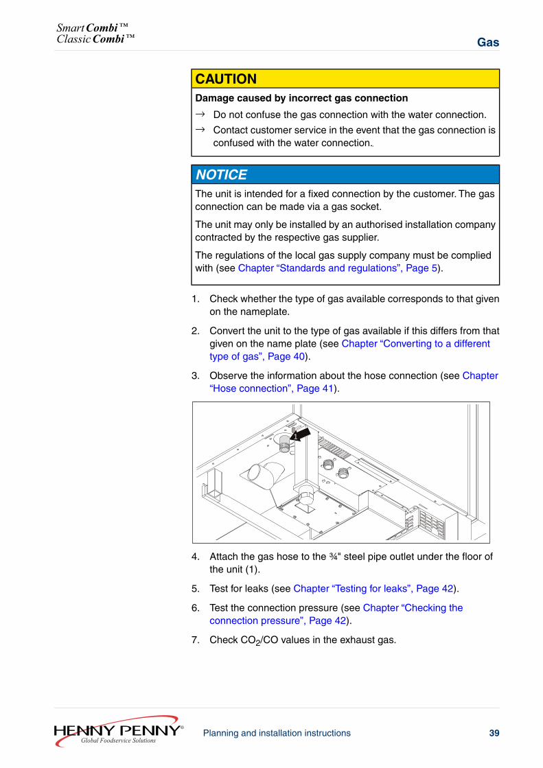
3. Observe the information about the hose connection (see Chapter“Hose connection”, Page 41).
1
4. Attach the gas hose to the ¾" steel pipe outlet under the floor ofthe unit (1).
5. Test for leaks (see Chapter “Testing for leaks”, Page 42).
6. Test the connection pressure (see Chapter “Checking theconnection pressure”, Page 42).
7. Check CO2/CO values in the exhaust gas.
39Planning and installation instructionsGlobal Foodservice Solutions
GasSmartCombi™ClassicCombi™
6.2 Converting to a different type of gas
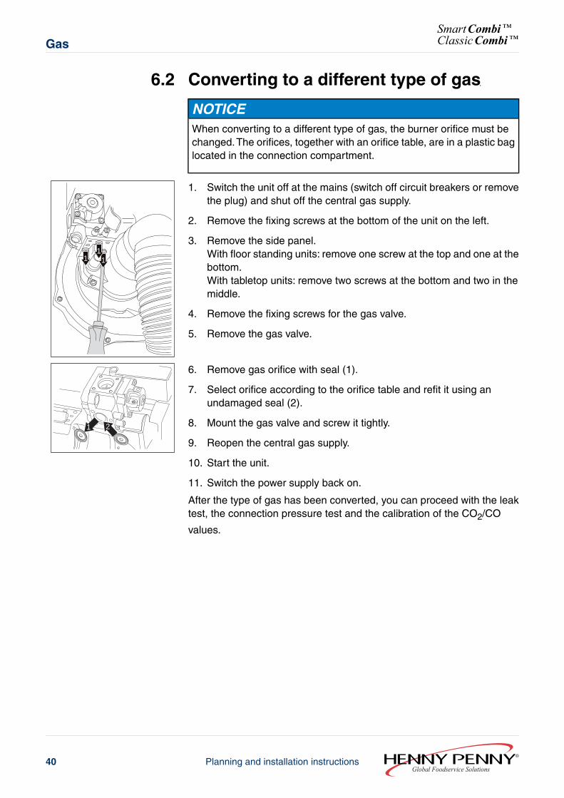
NOTICEWhen converting to a different type of gas, the burner orifice must bechanged.The orifices, together with an orifice table, are in a plastic baglocated in the connection compartment.
1 11
1. Switch the unit off at the mains (switch off circuit breakers or removethe plug) and shut off the central gas supply.
2. Remove the fixing screws at the bottom of the unit on the left.
3. Remove the side panel.With floor standing units: remove one screw at the top and one at thebottom.With tabletop units: remove two screws at the bottom and two in themiddle.
4. Remove the fixing screws for the gas valve.
5. Remove the gas valve.
1 2
6. Remove gas orifice with seal (1).
7. Select orifice according to the orifice table and refit it using anundamaged seal (2).
8. Mount the gas valve and screw it tightly.
9. Reopen the central gas supply.
10. Start the unit.
11. Switch the power supply back on.
After the type of gas has been converted, you can proceed with the leaktest, the connection pressure test and the calibration of the CO2/CO
values.
Global Foodservice SolutionsPlanning and installation instructions40
SmartCombi™ClassicCombi™Gas
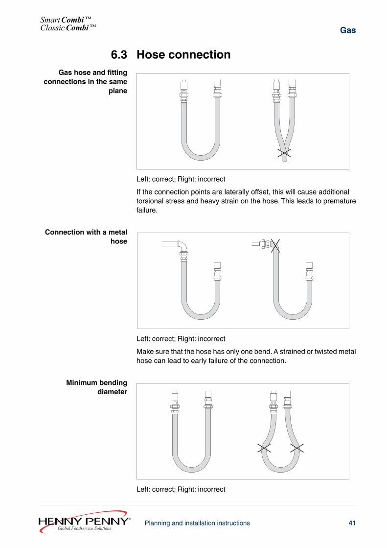
6.3 Hose connectionGas hose and fitting
connections in the sameplane
Left: correct; Right: incorrect
If the connection points are laterally offset, this will cause additionaltorsional stress and heavy strain on the hose. This leads to prematurefailure.
Connection with a metalhose
Left: correct; Right: incorrect
Make sure that the hose has only one bend. A strained or twisted metalhose can lead to early failure of the connection.
Minimum bendingdiameter
Left: correct; Right: incorrect
41Planning and installation instructionsGlobal Foodservice Solutions
GasSmartCombi™ClassicCombi™
If the separation between the two connection points is less than theminimum bending diameter, it results in the hose ends bending in oppositedirections. This leads to fatigue fractures.
6.4 Testing for leaks
NOTICEUse only DVGW-approved foam forming agents or those that have beentested according to locally applying regulations!
Do not spray leak spray onto the wires of the ignition electronics.
Electronic gas detectors also react to exhaust gas (CO). Therefore, thenull calibration of an electronic gas detector should be done outdoors.
→ Test all connections inside and outside the unit for leaks accordingto the “technical provisions for the gas installation” , using a gasdetector or leak spray.
6.5 Checking the connection pressureRequirements All connections inside and outside the unit are free of leaks (see Chapter
“Testing for leaks”, Page 42).
NOTICEThe manometer should be accurate to at least 0.1 mbar.
1. Switch the unit off at the mains (switch off circuit breakers or removethe plug) and shut off the central gas supply.
2. Unscrew the side panel.With tabletop units: remove one screw at the top and one at thebottom.With floor standing units, remove two screws at the bottom and twoin the middle.
Global Foodservice SolutionsPlanning and installation instructions42
SmartCombi™ClassicCombi™Gas
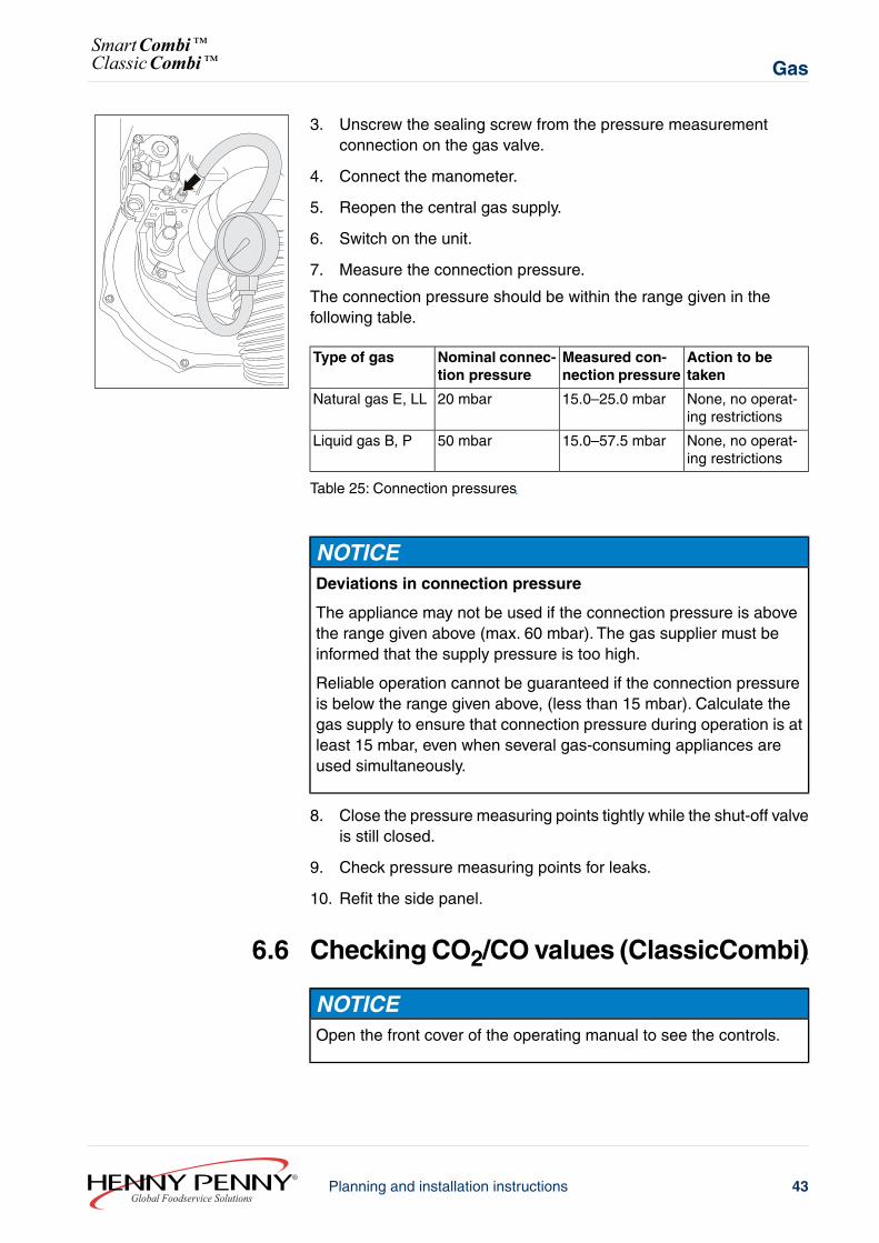
3. Unscrew the sealing screw from the pressure measurementconnection on the gas valve.
4. Connect the manometer.
5. Reopen the central gas supply.
6. Switch on the unit.
7. Measure the connection pressure.
The connection pressure should be within the range given in thefollowing table.
Action to betaken
Measured con-nection pressure
Nominal connec-tion pressure
Type of gas
None, no operat-ing restrictions
15.0–25.0 mbar20 mbarNatural gas E, LL
None, no operat-ing restrictions
15.0–57.5 mbar50 mbarLiquid gas B, P
Table 25: Connection pressures
NOTICEDeviations in connection pressure
The appliance may not be used if the connection pressure is abovethe range given above (max. 60 mbar). The gas supplier must beinformed that the supply pressure is too high.
Reliable operation cannot be guaranteed if the connection pressureis below the range given above, (less than 15 mbar). Calculate thegas supply to ensure that connection pressure during operation is atleast 15 mbar, even when several gas-consuming appliances areused simultaneously.
8. Close the pressure measuring points tightly while the shut-off valveis still closed.
9. Check pressure measuring points for leaks.
10. Refit the side panel.
6.6 Checking CO2/CO values (ClassicCombi)
NOTICEOpen the front cover of the operating manual to see the controls.
43Planning and installation instructionsGlobal Foodservice Solutions
GasSmartCombi™ClassicCombi™
6.6.1 Start CO2 calibration
WARNINGPossible danger
→ Non-compliance may pose a threat of death or serious injury.
NOTICEIf there is still air in the gas pipeline, display (8) will show the error “71”(no gas). Repeat the start procedure if this happens.
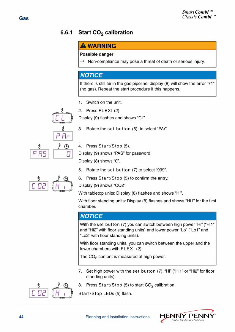
1. Switch on the unit.
C L2. Press FLEXI (2).
Display (9) flashes and shows “CL”.
P Ar3. Rotate the set button (6), to select “PAr”.
0P AS4. Press Star t /Stop (5).
Display (9) shows “PAS” for password.
Display (8) shows “0”.
5. Rotate the set button (7) to select “999”.
C O2 H i 6. Press Star t /Stop (5) to confirm the entry.
Display (9) shows “CO2”.
With tabletop units: Display (8) flashes and shows “Hi”.
With floor standing units: Display (8) flashes and shows “Hi1” for the firstchamber.
NOTICEWith the set button (7) you can switch between high power “Hi” (“Hi1”and “Hi2” with floor standing units) and lower power “Lo” (“Lo1” and“Lo2” with floor standing units).
With floor standing units, you can switch between the upper and thelower chambers with FLEXI (2).
The CO2 content is measured at high power.
7. Set high power with the set button (7). “Hi” (“Hi1” or “Hi2” for floorstanding units).
C O2 H i 8. Press Star t /Stop (5) to start CO2 calibration.
Star t /Stop LEDs (5) flash.
Global Foodservice SolutionsPlanning and installation instructions44
SmartCombi™ClassicCombi™Gas
Display (9) shows “CO2”.
Display (8) flashes and shows “Hi” (“Hi1” or “Hi2” for floor standingunits).
6.6.2 Measure CO2 values
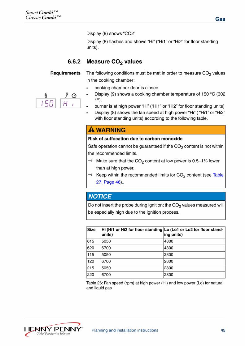
Requirements The following conditions must be met in order to measure CO2 values
in the cooking chamber:
● cooking chamber door is closed●
1 50 H i Display (9) shows a cooking chamber temperature of 150 °C (302°F).
● burner is at high power “Hi” (“Hi1” or “Hi2” for floor standing units)● Display (8) shows the fan speed at high power “Hi” ( “Hi1” or “Hi2”
with floor standing units) according to the following table.
WARNINGRisk of suffocation due to carbon monoxide
Safe operation cannot be guaranteed if the CO2 content is not within
the recommended limits.
→ Make sure that the CO2 content at low power is 0.5–1% lower
than at high power.→ Keep within the recommended limits for CO2 content (see Table
27, Page 46).
NOTICEDo not insert the probe during ignition; the CO2 values measured will
be especially high due to the ignition process.
Lo (Lo1 or Lo2 for floor stand-ing units)
Hi (Hi1 or Hi2 for floor standingunits)
Size
48005050615
48006700620
28005050115
28006700120
28005050215
28006700220
Table 26: Fan speed (rpm) at high power (Hi) and low power (Lo) for naturaland liquid gas
45Planning and installation instructionsGlobal Foodservice Solutions
GasSmartCombi™ClassicCombi™
NOTICETurn the set button (7) to switch between the upper and lowerchambers with floor standing units.
H i1Display (8) shows the selected chamber“Hi1” or “Hi2” and “Lo1” or “Lo2”.
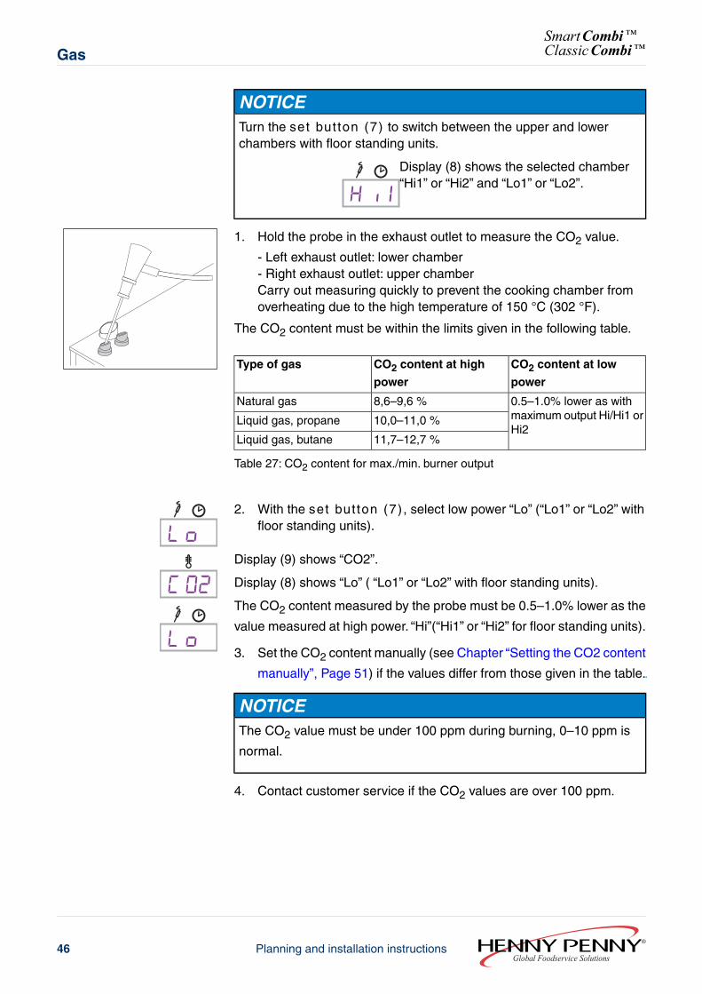
1. Hold the probe in the exhaust outlet to measure the CO2 value.
- Left exhaust outlet: lower chamber- Right exhaust outlet: upper chamberCarry out measuring quickly to prevent the cooking chamber fromoverheating due to the high temperature of 150 °C (302 °F).
The CO2 content must be within the limits given in the following table.
CO2 content at low
power
CO2 content at high
power
Type of gas
0.5–1.0% lower as withmaximum output Hi/Hi1 orHi2
8,6–9,6 %Natural gas
10,0–11,0 %Liquid gas, propane
11,7–12,7 %Liquid gas, butane
Table 27: CO2 content for max./min. burner output
L o 2. With the set button (7), select low power “Lo” (“Lo1” or “Lo2” with
floor standing units).
C O2Display (9) shows “CO2”.
L o
Display (8) shows “Lo” ( “Lo1” or “Lo2” with floor standing units).
The CO2 content measured by the probe must be 0.5–1.0% lower as the
value measured at high power. “Hi”(“Hi1” or “Hi2” for floor standing units).
3. Set the CO2 content manually (see Chapter “Setting the CO2 content
manually”, Page 51) if the values differ from those given in the table.
NOTICEThe CO2 value must be under 100 ppm during burning, 0–10 ppm is
normal.
4. Contact customer service if the CO2 values are over 100 ppm.
Global Foodservice SolutionsPlanning and installation instructions46
SmartCombi™ClassicCombi™Gas
6.6.3 Display burner status and cooking chambertemperature
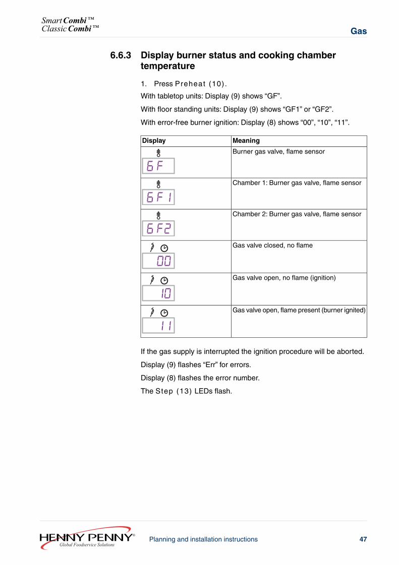
1. Press Preheat (10).
With tabletop units: Display (9) shows “GF”.
With floor standing units: Display (9) shows “GF1” or “GF2”.
With error-free burner ignition: Display (8) shows “00”, “10”, “11”.
MeaningDisplay
Burner gas valve, flame sensor
6 FChamber 1: Burner gas valve, flame sensor
6 F1Chamber 2: Burner gas valve, flame sensor
6 F2Gas valve closed, no flame
00Gas valve open, no flame (ignition)
10Gas valve open, flame present (burner ignited)
11
If the gas supply is interrupted the ignition procedure will be aborted.
Display (9) flashes “Err” for errors.
Display (8) flashes the error number.
The Step (13) LEDs flash.
47Planning and installation instructionsGlobal Foodservice Solutions
GasSmartCombi™ClassicCombi™
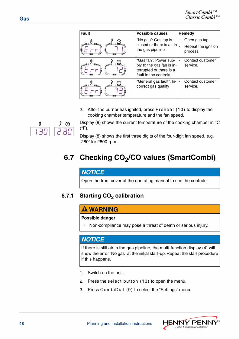
RemedyPossible causesFault
- Open gas tap.
- Repeat the ignitionprocess.
“No gas”: Gas tap isclosed or there is air inthe gas pipelineE rR 71
- Contact customerservice.
“Gas fan”: Power sup-ply to the gas fan is in-terrupted or there is afault in the controls
E rR 72- Contact customer
service.“General gas fault”: In-correct gas quality
E rR 73
2. After the burner has ignited, press Preheat (10) to display thecooking chamber temperature and the fan speed.
1 30 2 80Display (9) shows the current temperature of the cooking chamber in °C(°F).
Display (8) shows the first three digits of the four-digit fan speed, e.g.“280” for 2800 rpm.
6.7 Checking CO2/CO values (SmartCombi)
NOTICEOpen the front cover of the operating manual to see the controls.
6.7.1 Starting CO2 calibration
WARNINGPossible danger
→ Non-compliance may pose a threat of death or serious injury.
NOTICEIf there is still air in the gas pipeline, the multi-function display (4) willshow the error “No gas” at the initial start-up. Repeat the start procedureif this happens.
1. Switch on the unit.
2. Press the select but ton (13) to open the menu.
3. Press CombiDial (9) to select the “Settings” menu.
Global Foodservice SolutionsPlanning and installation instructions48
SmartCombi™ClassicCombi™Gas
4. PressCombiDial (9) to open the menu.
The multi-function display (4) shows „Password“ and „000“ .
5. Press CombiDial (9) to enter the password “999”.
6. PressCombiDial (9) to confirm the selection.
The multi-function display (4) shows “Calibr. gas CO2”.
7. Press Star t /Stop (8) to start the CO2 calibration.
The multi-function display (4) shows “High power”, the fan speed andthe cooking chamber temperature.
NOTICEWith floor standing units, you can switch between the upper and thelower chambers with the select but ton (13)“Change chamber”.The multi-function display (4) indicates the selected chamber with anarrow next to the fan speed.
The CO2 content is measured at high power.
6.7.2 Measuring CO2 values
Requirements The following conditions must be met in order to measure CO2 values
in the cooking chamber:
● Cooking chamber door is closed● Burner is at high power● The multi-function display (4) shows a cooking chamber
temperature of 150 °C (302 °F)● The multi-function display (4) shows the fan speed at full power
according to the following table.
WARNINGRisk of suffocation due to carbon monoxide
Safe operation cannot be guaranteed if the CO2 content is not within
the recommended limits.
→ Make sure that the CO2 content at low power is 0.5–1 % lower
than at high power.→ Keep within the recommended limits for CO2 content (see Table
29, Page 50).
NOTICEDo not insert the probe during ignition; the CO2 values measured will
be especially high due to the ignition process.
49Planning and installation instructionsGlobal Foodservice Solutions
GasSmartCombi™ClassicCombi™
Lo (Lo1 or Lo2 for units with twochambers)
Hi (Hi1 or Hi2 for units with twochambers)
Size
48005050615
48006700620
28005050115
28006700120
28005050215
28006700220
Table 28: Fan speed (rpm) at high power (Hi) and low power (Lo) for natural andliquid gas
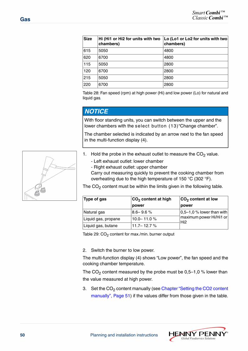
NOTICEWith floor standing units, you can switch between the upper and thelower chambers with the select but ton (13)“Change chamber”.
The chamber selected is indicated by an arrow next to the fan speedin the multi-function display (4).
1. Hold the probe in the exhaust outlet to measure the CO2 value.
- Left exhaust outlet: lower chamber- Right exhaust outlet: upper chamberCarry out measuring quickly to prevent the cooking chamber fromoverheating due to the high temperature of 150 °C (302 °F).
The CO2 content must be within the limits given in the following table.
CO2 content at low
power
CO2 content at high
power
Type of gas
0,5–1,0 % lower than withmaximum power Hi/Hi1 orHi2
8.6– 9.6 %Natural gas
10.0– 11.0 %Liquid gas, propane
11.7– 12.7 %Liquid gas, butane
Table 29: CO2 content for max./min. burner output
2. Switch the burner to low power.
The multi-function display (4) shows “Low power”, the fan speed and thecooking chamber temperature.
The CO2 content measured by the probe must be 0,5–1,0 % lower than
the value measured at high power.
3. Set the CO2 content manually (see Chapter “Setting the CO2 content
manually”, Page 51) if the values differ from those given in the table.
Global Foodservice SolutionsPlanning and installation instructions50
SmartCombi™ClassicCombi™Gas
NOTICEThe CO2 value must be under 100 ppm during burning, 0–10 ppm is
normal.
4. Contact customer service if the CO2 values are over 100 ppm.
6.8 Setting the CO2 content manually
The CO2 content must be set manually if the values differ from those
given in the table.
NOTICEWhen the CO2 content has been set for low power, the CO2 content
must subsequently be remeasured at high power.
Both settings interact with each other.
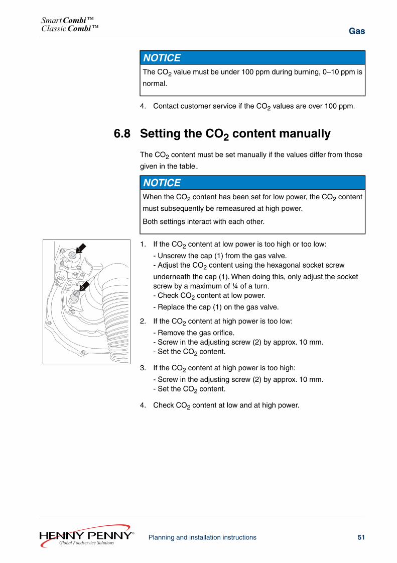
1
2
1. If the CO2 content at low power is too high or too low:
- Unscrew the cap (1) from the gas valve.- Adjust the CO2 content using the hexagonal socket screw
underneath the cap (1). When doing this, only adjust the socketscrew by a maximum of ¼ of a turn.- Check CO2 content at low power.
- Replace the cap (1) on the gas valve.
2. If the CO2 content at high power is too low:
- Remove the gas orifice.- Screw in the adjusting screw (2) by approx. 10 mm.- Set the CO2 content.
3. If the CO2 content at high power is too high:
- Screw in the adjusting screw (2) by approx. 10 mm.- Set the CO2 content.
4. Check CO2 content at low and at high power.
51Planning and installation instructionsGlobal Foodservice Solutions
GasSmartCombi™ClassicCombi™
7 Exhaust gas routingWARNING
Risk of fire due to combustion gases and hot surfaces
The exhaust flue connection and its covering can become extremelyhot and cause burns in cases of direct contact.
→ The temperature of the exhaust gas can reach 400 °C (752 °F).Plan and carry out the installation of the unit in such a way as toavoid contact with flammable surfaces.
→ Do not place any objects close to or on the unit.→ Maintain sufficient distance to fat filters in customer supplied
extraction hoods.→ Use a ventilation cover (accessory) to reduce exhaust temperatures.→ Only allow gas supply to the burners when the extraction system
is working.
WARNINGDanger of poisoning by exhaust fumes
→ Ensure, during planning and installation, that exhaust fumes aretransported to the open air.
→ Install extraction systems such as extraction hoods, chimneys andventilation covers.
→ Ensure that all users know the fire prevention regulations.
NOTICEIn order to prevent an unacceptable build-up of harmful combustionproducts, the units must be installed under extraction systems (roomventilation system with safety switch). When installing the appliancebeneath a ventilation cover or an extractor hood system, safety devicesmust be in place that allow gas supply to the burners only when theextraction system is working.
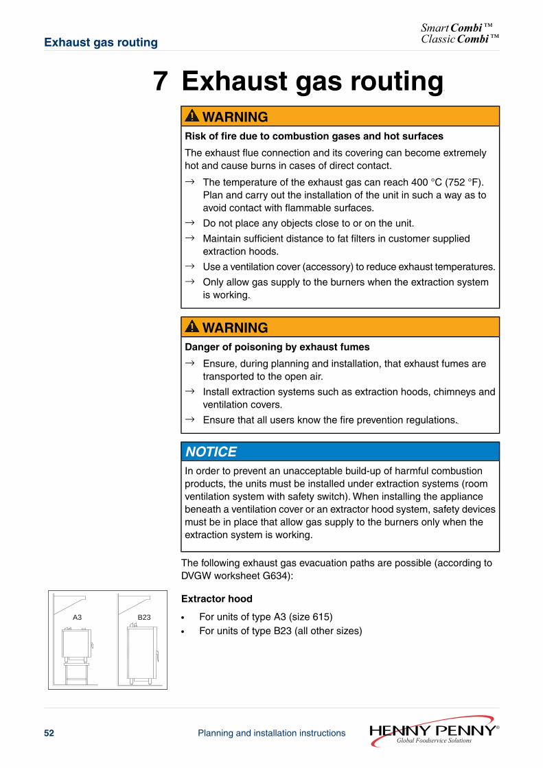
The following exhaust gas evacuation paths are possible (according toDVGW worksheet G634):
B23A3
Extractor hood
● For units of type A3 (size 615)● For units of type B23 (all other sizes)
Global Foodservice SolutionsPlanning and installation instructions52
SmartCombi™ClassicCombi™Exhaust gas routing
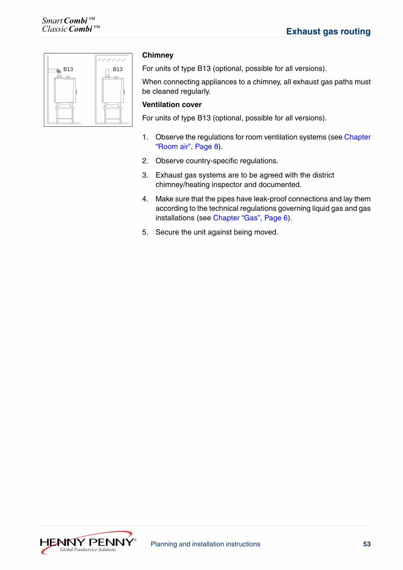
B13B13
Chimney
For units of type B13 (optional, possible for all versions).
When connecting appliances to a chimney, all exhaust gas paths mustbe cleaned regularly.
Ventilation cover
For units of type B13 (optional, possible for all versions).
1. Observe the regulations for room ventilation systems (see Chapter“Room air”, Page 8).
2. Observe country-specific regulations.
3. Exhaust gas systems are to be agreed with the districtchimney/heating inspector and documented.
4. Make sure that the pipes have leak-proof connections and lay themaccording to the technical regulations governing liquid gas and gasinstallations (see Chapter “Gas”, Page 6).
5. Secure the unit against being moved.
53Planning and installation instructionsGlobal Foodservice Solutions
Exhaust gas routingSmartCombi™ClassicCombi™
8 Air outlet connectionWaste steam and vapours are cooled by the built-in cooling system andextracted via the drain; an air extraction system is therefore not essential.
Installation under an extraction hood is recommended.
8.1 Installation under an extraction hood→ Observe the regulations for room ventilation systems (see Chapter
“Room air”, Page 8).
8.2 Connection to an air outlet ductRequirements Connection with a pipe
● Do not use galvanized pipes.● Heat-proof and non-corrosive pipe (e.g. PA-I 1818 DIN 19560 HT
pipe)Connection with a hose
● Do not use aluminium tubes because tube corrosion might occur.● Heat-proof to at least 180 °C (356 °F)● Hose diameter
With tabletop units: 53 mmWith floor standing units: 73 mm
● Hose length max. 2.5 m
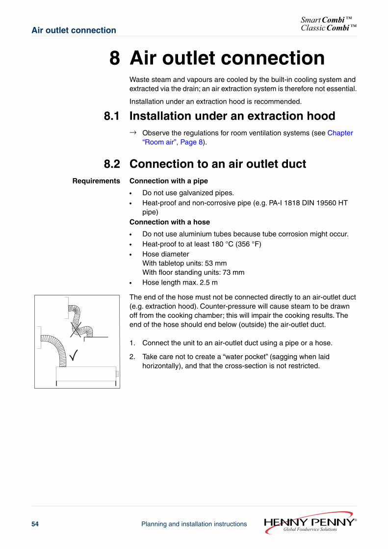
The end of the hose must not be connected directly to an air-outlet duct(e.g. extraction hood). Counter-pressure will cause steam to be drawnoff from the cooking chamber; this will impair the cooking results. Theend of the hose should end below (outside) the air-outlet duct.
1. Connect the unit to an air-outlet duct using a pipe or a hose.
2. Take care not to create a “water pocket” (sagging when laidhorizontally), and that the cross-section is not restricted.
Global Foodservice SolutionsPlanning and installation instructions54
SmartCombi™ClassicCombi™Air outlet connection
Planning and installation instructions
SmartCombi™ClassicCombi™
Global Foodservice Solutions
Henny Penny CorporationP.O. Box 60Eaton, OH 45320
1-937-456-84001-937-456-8402 Fax Toll free in USA 1-800-417-84171-800-417-8434 Fax
www.hennypenny.com
Manufactured by: MKN MaschinenfabrikWolfenb¿ttel, Germany
Planning and installation instructions
SmartCombi™ClassicCombi™