Embed Size (px)
Citation preview

37 SUMMIT STREET, BRIGHTON, MI 48116(810) 227-2266 FAX: (810) 227-5566
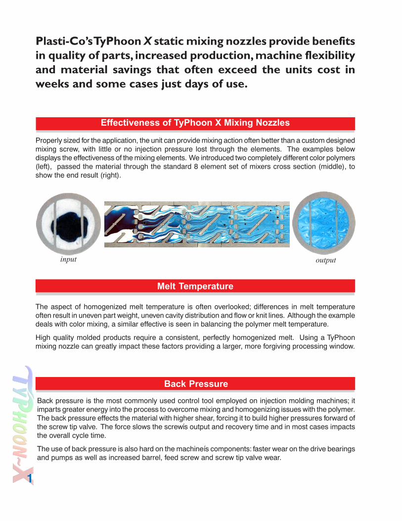
Plasti-Co’s TyPhoon X static mixing nozzles provide benefitsin quality of parts, increased production, machine flexibilityand material savings that often exceed the units cost inweeks and some cases just days of use.
Properly sized for the application, the unit can provide mixing action often better than a custom designedmixing screw, with little or no injection pressure lost through the elements. The examples belowdisplays the effectiveness of the mixing elements. We introduced two completely different color polymers(left), passed the material through the standard 8 element set of mixers cross section (middle), toshow the end result (right).
The aspect of homogenized melt temperature is often overlooked; differences in melt temperatureoften result in uneven part weight, uneven cavity distribution and flow or knit lines. Although the exampledeals with color mixing, a similar effective is seen in balancing the polymer melt temperature.
High quality molded products require a consistent, perfectly homogenized melt. Using a TyPhoonmixing nozzle can greatly impact these factors providing a larger, more forgiving processing window.
Back pressure is the most commonly used control tool employed on injection molding machines; itimparts greater energy into the process to overcome mixing and homogenizing issues with the polymer.The back pressure effects the material with higher shear, forcing it to build higher pressures forward ofthe screw tip valve. The force slows the screwís output and recovery time and in most cases impactsthe overall cycle time.
The use of back pressure is also hard on the machineís components: faster wear on the drive bearingsand pumps as well as increased barrel, feed screw and screw tip valve wear.
Back Pressure
Melt Temperature
Effectiveness of TyPhoon X Mixing Nozzles
1
input output
37 SUMMIT STREET, BRIGHTON, MI 48116(810) 227-2266 FAX: (810) 227-5566
Temperature
The second most commonly used tool to improve polymer consistency is increased temperature settings;this can degrade the polymer reducing the quality and integrity of the molded part. Employing aTyPhoon X static mixer will not over-shear or degrade the polymer and may allow for lower overalltemperature settings which can result in shorter cooling time in the tool and improved overall cycletime.
Reductions of color additives of as much as 30%have been achieved with comparable part colordensity. The use of lower cost color additives thatwere unusable in the past often become anoption.
A common problem for molders is processingun-even regrind materials, resulting in poor meltquality. A TyPhoon X mixing nozzle can allow orincrease the level of regrind that can successfullybe processed.
Improved cycle times mean improved profitability,with reduced temperature and cooling times cycletime can be reduced. Lower screw back pressureincreases screw output and recovery time.
TyPhoon will make the process significantly morestable, allowing for less impact from factors thatare difficult to control; like ambient temperaturechanges, material inconsistency, and operatorcycle time inconsistency. A stable process willresult in less scrap and rejects.
RRRRRReturn on InvestmentReturn on Investment
RegrindColorant
Cycle Time Rejects
• Quality, Costs and Speed can provide added benefits and cost savings.• Improved Foam Cell Size and Distribution• Improved Part Quality with Regrind• Lower Part Weight Variations• Improved Color Distribution• Reduced Colorant Usage• Reduced Scrap Rates• Improved Melt Flow• Faster Cycle Times
2

The TyPhoon X mixing elements are built usinga modular design, making them flexible interms of the number of elements that canbe employed and easy to service andclean.
The elements are manufactured from highstrength 17-4PH stainless steel, providingboth high corrosion resistance and thetensile strength to withstand high pressuremolding conditions.
The elements design providessmooth polymer flow using a
double-roof peak design. Thinblade design achievable due tofully supported integral onepiece casting with multi-pointload transference, results in 30-
50% higher flow volumes andlower pressure drop than other
designs.
Mixing Elements
End view of TyPhoon X element
TyPhoon X units generally consist of 8 mixing elements; this provides the greatest mixingaction generally required for injection molding applications. The units with more or less elementsare commonly supplied for non-standard applications. The 8-element set provides 4 full L/Dratio of mixing area.
TyPhoon X elements are offered in 6 different inside diameters or flow areas; the proper size elementwill provide excellent blending action with little or no noticeable injection pressure loss through themixer.
The chart below will help determine the proper size for your machine and application. The machine itis to be used on should determine element size and its ratings, not the molded part size.
The proper size unit is based on the many factors, mainly the viscosity of the polymer(s) to be processedand the injection flow rate through the machines nozzle. Providing Plasti-Co with a completed ìTechnicalSpecifications Questionnaireî located in the back of this brochure will allow us to provide you with theproper size unit for your machine and application.
EEEEEElement Number and SizeElement Number and SizeNumber of Elements
Element Size
Model Number
Internal Flow Area mm / inches
Screw Size Range
Machine Shot Size Range
Injection Flow Rate - cm
cubed / secondAvailability
TSM 12 12mm / .472" 15 - 22mm .8 - 4 oz. < 200 Upon RequestTSM 18 18mm / .708" 22 - 60mm 5 - 28 oz. < 700 In StockTSM 22 22mm / .866" 60 - 95mm 28 - 80 oz. < 1200 In StockTSM 27 27mm / 1.063" 95 - 140mm 80 - 300 oz. < 2300 In StockTSM 33 33mm / 1.299" 140 - 180mm 300 - 600 oz. < 3700 In StockTSM 40 40mm / 1.574" 180 - 260mm 600 - 800 oz. < 7000 Upon Request
Element Sizes Process Sizes
MMMMMMixing Elements
3

37 SUMMIT STREET, BRIGHTON, MI 48116(810) 227-2266 FAX: (810) 227-5566
NNNNNTyPhoon X nozzle housings are
manufactured from heat-treated alloy
steel or high quality stainless steel for
corrosive applications. Designed to be
installed directly into your machineís end
cap (nozzle adapter) our unique two-piece
design allows for very easy installation
and removal of the mixing elements for
cleaning or service. Durable construction with large hex areas forinstallation will provide excellent service life.
TyPhoon X nozzles are sold as complete assemblies; everything you need to operate and service theunit is supplied. The units are shipped assembled, however, the nozzle housing must be dissembled to
Assembly includes:
1) Mixing Element Set: proper size and number of yourapplication.
2) TyPhoon X Element: standard high flow X element, optionalXF filter element or XM additional mixing elements.
3) Nozzle Body Housing: 2 part assembly including mainelement housing and discharge adapter.
4) Heaters: high quality mica insulated heaters with 36î wirebraid lead wires. Designed with the specific watt density andpower distribution required for proper operation of the unit.
5) Nozzle tip: TyPhoon X units available with a standard7/8î - 14-thread nozzle tip on the TSM 18, 22, 27 and a standard1-1/4î - 12 thread nozzle tip for the TSM 27 and 33. The orificeand radius is supplied to match your mold.
6) Thermocouple: nozzle type unit with 1/4î - 28 NPT thread,with 72î of durable wire braid lead.
7) Operating and Instruction Manual: provides the informationneeded for proper usage, installation and service of your mixingnozzle.
8) Wrench & Anti-Seize: tool for installation and service of theheater bands and Plasti-Coís premium copper/graphite anti-seizecompound.
Complete Assemblies
4
Nozzle Body HousingNozzle Body HousingNozzle Body HousingNozzle Body HousingNozzle Body HousingNozzle Body Housing
CCCCCComplete AssembliesComplete Assemblies
apply anti-seize and installed on the machine in the proper stages.

TyPhoon X
TyPhoon XF
TyPhoon XM
The Typhoon-X system uses ourstandard eight piece modular mixingelements coupled with our X element.The X element provides systemflexibility and makes it possible tointerchange between standard, filter andadded mixing configurations. The Xelement also gives the added benefit ofaiding the in the safe and easy removalthe mixing elements.
The Typhoon-XF system uses a highlyefficient filter element. The filter elementuses grooves to filter the melt with eightlongitudinal channels, four inflowchannels and four outflow channels. Themelt must pass through the radialgrooves to exit the filter. These groovestrap contaminants or un-melt larger thanthe groove width. Once the melt passesthrough the filter it continues through thestandard Typhoon mixing elementassembly.
The Typhoon-XM system offersadditional mixing capability. Itreplaces the standard X elementwith a combination of a Short Xelement and two additionalTyphoon mixing elements. Thisconfiguration provides a full 5 L/Dratio of mixing area.
OOOOOOptional Configurations
X Element
XF Filter Element
5
Standard set of 8Mixing Elements
Standard set of 8Mixing Elements
Short X Element
Standard set of 10Mixing Elements
Element Housing
Discharge Adapter

37 SUMMIT STREET, BRIGHTON, MI 48116(810) 227-2266 FAX: (810) 227-5566
Disturbing the laminar flow which forces material faster through the center of the nozzle than the sideor along the wall. Moving these layers from center to sides and back creates very turbulent flow, thusblending the polymer.
Plasti-Co offers limited trials on TyPhoon X mixing nozzles. The trials allow our customersto test the performance of the product for their needs and process. These trials are limited.Contact Plasti-Co for details.
The example to left showsthe extent of the mixingaction at each of thestandard eight elementstages.
This example shows thesame test results in a crosssection.
How a TyPhoon Works
Trial Testing
6

37 SUMMIT STREET, BRIGHTON, MI 48116(810) 227-2266 FAX: (810) 227-5566
Total Wattage: Amp Draw @ 120 Volts: Amp Draw @ 240 Volts:PowerRequirement: 1090 9.08 4.54
TSM18N-D29.64”
2.75”
1.50”
2.125”
TSM18N-D3
Total Wattage: Amp Draw @ 120 Volts: Amp Draw @ 240 Volts:PowerRequirement: 1250 10.41 5.20
10.64”
3.75”
1.50”
2.125”
Model Number:TSM18N-D(X)
Internal Flow Area:18mm / .708”
Screw Size Range:35 - 50mm
Machine Shot SizeRange:
8 - 16 oz.Injection Flow Ratecm - cubed/second:
<700Main Body OutsideDiameter:
2.125”Minimum LengthForward of End Cap:
7.25”Minimum Input threadSize:
1.00” / 25mmNozzle Tip Thread(standard):
7/8” - 14Discharge NozzleOutside diameter:
1.50”
TSM18N-D1
Total Wattage: Amp Draw @ 120 Volts: Amp Draw @ 240 Volts:PowerRequirement: 1000 8.33 4.16
8.64”
1.50”
1.75”
2.125”
SEE PAGE 5FOR MIXING OPTIONS
7

TSM18N-D5
Total Wattage: Amp Draw @ 120 Volts: Amp Draw @ 240 Volts:
Power Requirement: 1550 12.92 6.45
12.64”
1.50”
2.125”
5.75”
TSM18N-D6
Total Wattage: Amp Draw @ 120 Volts: Amp Draw @ 240 Volts:
Power Requirement: 1550 12.92 6.45
13.64”
6.75”
1.50”
2.125”
TSM18N-D4
Total Wattage: Amp Draw @ 120 Volts: Amp Draw @ 240 Volts:
Power Requirement: 1400 11.66 5.83
11.64”
4.75”
1.50”
2.125”
8
SEE PAGE 5FOR MIXING OPTIONS

37 SUMMIT STREET, BRIGHTON, MI 48116(810) 227-2266 FAX: (810) 227-5566
Model Number:TSM22N-D(X)
Internal Flow Area:22mm / .866”
Screw Size Range:50 - 80mm
Machine Shot SizeRange:
16 - 65 oz.Injection Flow Ratecm - cubed/second:
<1200Main Body OutsideDiameter:
2.75”Minimum LengthForward of End Cap:
8.75”Minimum Input threadSize:
1.25” / 32mmNozzle Tip Thread(standard):
7/8” - 14Discharge NozzleOutside diameter:
1.50”
TSM22N-D2
Total Wattage: Amp Draw @ 120 Volts: Amp Draw @ 240 Volts:PowerRequirement: 1465 12.20 6.10
SEE PAGE 6FOR MIXING OPTIONS
TSM22N-D3
Total Wattage: Amp Draw @ 120 Volts: Amp Draw @ 240 Volts:PowerRequirement: 1625 13.54 6.77
SEE PAGE 6FOR MIXING OPTIONS
TSM22N-D1
Total Wattage: Amp Draw @ 120 Volts: Amp Draw @ 240 Volts:PowerRequirement: 1375 11.45 5.73
SEE PAGE 6FOR MIXING OPTIONS
1.50”
1.50”
1.50”
9.83”
10.83”
11.83”
2.75”
2.75”
2.75”
1.75”
2.75”
3.75”
9
SEE PAGE 5FOR MIXING OPTIONS

TSM22N-D6
TSM22N-D5
TSM22N-D4
TSM22N-D0
Total Wattage: Amp Draw @ 120 Volts: Amp Draw @ 240 Volts:
Power Requirement: 1775 14.80 7.40
Total Wattage: Amp Draw @ 120 Volts: Amp Draw @ 240 Volts:
Power Requirement: 1775 14.80 7.40
Total Wattage: Amp Draw @ 120 Volts: Amp Draw @ 240 Volts:
Power Requirement: 1925 16.04 8.02
1.50”
1.50”
1.50”
12.83”
13.83”
14.83”
2.75”
2.75”
2.75”
4.75”
5.75”
6.75”
10Total Wattage: Amp Draw @ 120 Volts: Amp Draw @ 240 Volts:
Power Requirement: 1125 9.37 4.682.75”
8.30”
Standard Nozzle Body & Tip (Not Included)
1 3/4 - 8 Discharge thread acceptsyour standard nozzle bodies.
SEE PAGE 5FOR MIXING OPTIONS
37 SUMMIT STREET, BRIGHTON, MI 48116(810) 227-2266 FAX: (810) 227-5566
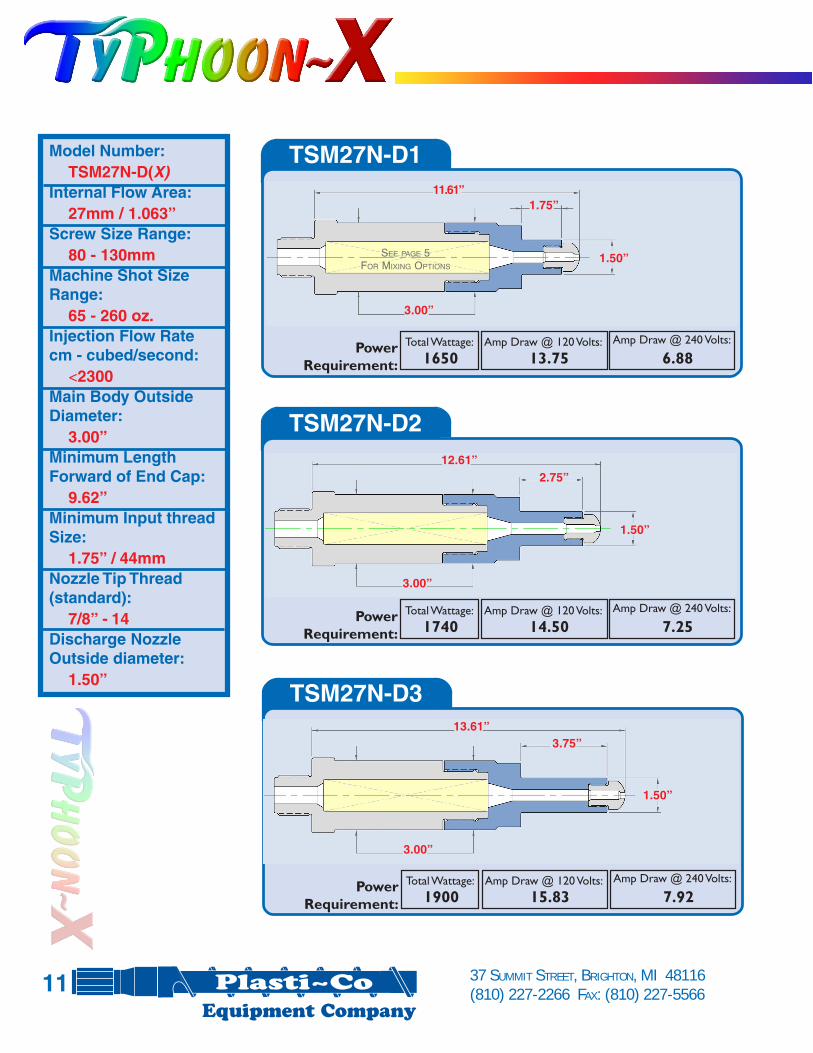
TSM27N-D1
Total Wattage: Amp Draw @ 120 Volts: Amp Draw @ 240 Volts:PowerRequirement: 1650 13.75 6.88
TSM27N-D2
Total Wattage: Amp Draw @ 120 Volts: Amp Draw @ 240 Volts:PowerRequirement: 1740 14.50 7.25
TSM27N-D3
Total Wattage: Amp Draw @ 120 Volts: Amp Draw @ 240 Volts:PowerRequirement: 1900 15.83 7.92
Model Number:TSM27N-D(X)
Internal Flow Area:27mm / 1.063”
Screw Size Range:80 - 130mm
Machine Shot SizeRange:
65 - 260 oz.Injection Flow Ratecm - cubed/second:
<2300Main Body OutsideDiameter:
3.00”Minimum LengthForward of End Cap:
9.62”Minimum Input threadSize:
1.75” / 44mmNozzle Tip Thread(standard):
7/8” - 14Discharge NozzleOutside diameter:
1.50”
3.00”
3.00”
12.61”
13.61”
1.50”
1.50”
2.75”
3.75”
11.61”1.75”
1.50”
3.00”
11
SEE PAGE 5FOR MIXING OPTIONS

TSM27N-D4
TSM27N-D5
TSM27N-D0
TSM27N-D6
Total Wattage: Amp Draw @ 120 Volts: Amp Draw @ 240 Volts:
Power Requirement: 2050 17.08 8.54
Total Wattage: Amp Draw @ 120 Volts: Amp Draw @ 240 Volts:
Power Requirement: 2200 18.33 9.17
Total Wattage: Amp Draw @ 120 Volts: Amp Draw @ 240 Volts:
Power Requirement: 2200 18.33 9.173.00”
3.00”
3.00”
14.61”
15.61”
16.61”
1.50”
1.50”
1.50”
4.75”
6.75”
5.75”
12Total Wattage: Amp Draw @ 120 Volts: Amp Draw @ 240 Volts:
Power Requirement: 1400 11.66 5.83
Standard Nozzle Body & Tip (Not Included)
1 3/4 - 8 Discharge thread acceptsyour standard nozzle bodies.
3.00”
9.78”
SEE PAGE 5FOR MIXING OPTIONS

37 SUMMIT STREET, BRIGHTON, MI 48116(810) 227-2266 FAX: (810) 227-5566
TSM27N-DB1
Total Wattage: Amp Draw @ 120 Volts: Amp Draw @ 240 Volts:PowerRequirement: 1615 13.75 6.73
TSM27N-DB2
Total Wattage: Amp Draw @ 120 Volts: Amp Draw @ 240 Volts:PowerRequirement: 1800 15.00 7.50
TSM27N-DB3
Total Wattage: Amp Draw @ 120 Volts: Amp Draw @ 240 Volts:PowerRequirement: 1975 16.46 8.23
Model Number:TSM27N-DB(X)
Internal Flow Area:27mm / 1.063”
Screw Size Range:80 - 130mm
Machine Shot SizeRange:
65 - 260 oz.Injection Flow Ratecm - cubed/second:
<2300Main Body OutsideDiameter:
3.00”Minimum LengthForward of End Cap:
9.75”Minimum Input threadSize:
1.75” / 44mmNozzle Tip Thread(standard):
1 1/4” - 12Discharge NozzleOutside diameter:
1.75”
3.00”
3.00”
3.00”
1.75”
1.75”
1.75”
1.75”
2.75”
3.75”
12.71”
11.71”
13.71”
13
SEE PAGE 5FOR MIXING OPTIONS

TSM27N-DB6
Total Wattage: Amp Draw @ 120 Volts: Amp Draw @ 240 Volts:
Power Requirement: 2300 19.16 9.583.00”
1.75”
6.75”
16.71”
TSM27N-DB5
Total Wattage: Amp Draw @ 120 Volts: Amp Draw @ 240 Volts:
Power Requirement: 2300 19.16 9.583.00”
1.75”
5.75”
15.71”
TSM27N-DB4
Total Wattage: Amp Draw @ 120 Volts: Amp Draw @ 240 Volts:
Power Requirement: 2140 17.83 8.913.00”
1.75”
4.75”
14.71”
14
SEE PAGE 5FOR MIXING OPTIONS

37 SUMMIT STREET, BRIGHTON, MI 48116(810) 227-2266 FAX: (810) 227-5566
TSM33N-DB1
Total Wattage: Amp Draw @ 120 Volts: Amp Draw @ 240 Volts:PowerRequirement: 2265 18.87 9.43
TSM33N-DB2
Total Wattage: Amp Draw @ 120 Volts: Amp Draw @ 240 Volts:PowerRequirement: 2390 19.91 9.95
TSM33N-DB3
Total Wattage: Amp Draw @ 120 Volts: Amp Draw @ 240 Volts:PowerRequirement: 2625 21.87 10.93
Model Number:TSM33N-DB(X)
Internal Flow Area:33mm / 1.30”
Screw Size Range:130 - 160mm
Machine Shot SizeRange:
260 - 330oz.Injection Flow Ratecm - cubed/second:
<3700Main Body OutsideDiameter:
3.50”Minimum LengthForward of End Cap:
12.25”Minimum Input threadSize:
2.00” / 50mmNozzle Tip Thread(standard):
1 1/4” - 12Discharge NozzleOutside diameter:
1.75”
1.75”
1.75”
1.75”
3.50”
3.50”
3.50”
3.75”
1.75”
2.75”
13.45”
14.45”
15.45”
15
SEE PAGE 5FOR MIXING OPTIONS

TSM33N-DB4
TSM33N-DB5
TSM33N-DB0
TSM33N-DB6
Total Wattage: Amp Draw @ 120 Volts: Amp Draw @ 240 Volts:
Power Requirement: 2950 24.58 12.29
Total Wattage: Amp Draw @ 120 Volts: Amp Draw @ 240 Volts:
Power Requirement: 2950 24.58 12.29
Total Wattage: Amp Draw @ 120 Volts: Amp Draw @ 240 Volts:
Power Requirement: 2790 23.25 11.62
1.75”
1.75”
1.75”
3.50”
3.50”
3.50”
4.75”
5.75”
6.75”
16.45”
17.45”
18.45”
163.50”
12.45”
1 3/4 - 8 Discharge thread acceptsyour standard nozzle bodies.
Standard Nozzle Body & Tip (Not Included)
Total Wattage: Amp Draw @ 120 Volts: Amp Draw @ 240 Volts:
Power Requirement: 1950 16.25 8.13
SEE PAGE 5FOR MIXING OPTIONS
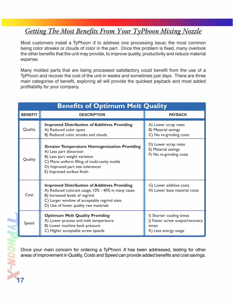
Most customers install a TyPhoon X to address one processing issue; the most commonbeing color streaks or clouds of color in the part. Once this problem is fixed, many overlookthe other benefits that the unit may provide, to improve quality, productivity and reduce materialexpense.
Many molded parts that are being processed satisfactory could benefit from the use of aTyPhoon and recover the cost of the unit in weeks and sometimes just days. There are threemain categories of benefit, exploring all will provide the quickest payback and most addedprofitability for your company.
Once your main concern for ordering a TyPhoon X has been addressed, testing for otherareas of improvement in Quality, Costs and Speed can provide added benefits and cost savings.
Getting The Most Benefits From Your TyPhoon Mixing Nozzle
17
BENEFIT PAYBACK
Benefits of Optimum Melt QualityDESCRIPTION
QualityImproved Distribution of Additives ProvidingA) Reduced color spotsB) Reduced color streaks and clouds
Greater Temperature Homogenization ProvidingA) Less part distortionB) Less part weight variationC) More uniform filling of multi-cavity moldsD) Improved part size tolerancesE) Improved surface finish
A) Lower scrap ratesB) Material savingsC) No re-grinding costs
Improved Distribution of Additives ProvidingA) Reduced colorant usage; 10% - 40% in many casesB) Increased levels of regrindC) Larger window of acceptable regrind sizesD) Use of lower quality raw materials
Optimum Melt Quality ProvidingA) Lower process and melt temperatureB) Lower machine back pressureC) Higher acceptable screw speeds
G) Lower additive costsH) Lower base material costs
I) Shorter cooling timesJ) Faster screw output/recoverytimesK) Less energy usage
Quality
Cost
Speed
D) Lower scrap ratesE) Material savingsF) No re-grinding costs
37 SUMMIT STREET, BRIGHTON, MI 48116(810) 227-2266 FAX: (810) 227-5566
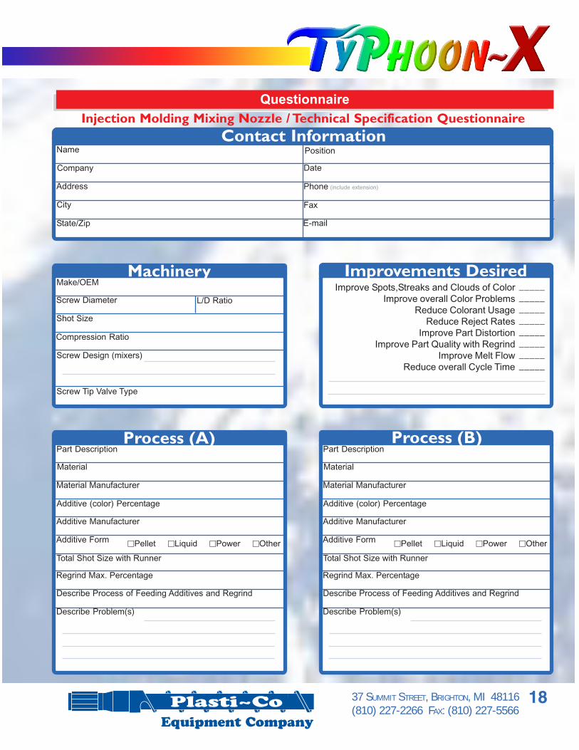
QuestionnaireInjection Molding Mixing Nozzle / Technical Specification Questionnaire
Improve Spots,Streaks and Clouds of ColorImprove overall Color Problems
Reduce Colorant UsageReduce Reject Rates
Improve Part DistortionImprove Part Quality with Regrind
Improve Melt FlowReduce overall Cycle Time
Improvements Desired________________________________________
Name
Company
Address
Position
City
State/Zip
Date
Phone (include extension)
Fax
Contact Information
Make/OEM
Screw Diameter
Shot Size
Compression Ratio
Screw Design (mixers)
Screw Tip Valve Type
Machinery
Part Description
Material
Material Manufacturer
Additive (color) Percentage
Additive Manufacturer
Total Shot Size with Runner
Additive Form GPellet GLiquid GPower GOther
Regrind Max. Percentage
Describe Process of Feeding Additives and Regrind
Describe Problem(s)
Process (A)Part Description
Material
Material Manufacturer
Additive (color) Percentage
Additive Manufacturer
Total Shot Size with Runner
Additive Form GPellet GLiquid GPower GOther
Regrind Max. Percentage
Describe Process of Feeding Additives and Regrind
Describe Problem(s)
Process (B)
L/D Ratio
18

NNNNNOZZLEOZZLEOZZLEOZZLEOZZLE S S S S SPECIFICAPECIFICAPECIFICAPECIFICAPECIFICATIONSTIONSTIONSTIONSTIONSNNNNNOZZLEOZZLEOZZLEOZZLEOZZLE S S S S SPECIFICAPECIFICAPECIFICAPECIFICAPECIFICATIONSTIONSTIONSTIONSTIONS
G120 G240 G other (please state)
G J G K G other (please state)
G3/4 G1/2” G other (please state)
Gzero G1-3/4” G2-3/4” G3-3/4” G4-3/4” G5-3/4” G6-3/4” G other
Nozzle Heater Voltage
Thermocouple Type
Nozzle Tip Radius Size
Nozzle Extension at Discharge*
The required information should be taken from the current nozzle. (see drawing below)
Thread length
Rear opening
IIIIINPUTNPUTNPUTNPUTNPUT - M - M - M - M - MAAAAACHINECHINECHINECHINECHINE S S S S SIDEIDEIDEIDEIDE OFOFOFOFOF U U U U UNITNITNITNITNITIIIIINPUTNPUTNPUTNPUTNPUT - M - M - M - M - MAAAAACHINECHINECHINECHINECHINE S S S S SIDEIDEIDEIDEIDE OFOFOFOFOF U U U U UNITNITNITNITNIT
Relief length
Relief diameter
ABCDE
Customer
Contact Person
Machine Make
Date
Machine Model
Shot Size
(right / left hand pitch)
This length must be longer than the depth of the machines nozzle adapter to allow forproper sealing.If unsure of thread size, provide the major OD of the very tops of the threads. Threadpitch should be taken with a pitch gage.
Rear opening size should match end cap (nozzle adapter) for proper flow.
Some machine makes will have long relief areas or counter bores for added sealing andalignment
AAAAADDITIONDDITIONDDITIONDDITIONDDITIONALALALALAL I I I I INFORMANFORMANFORMANFORMANFORMATIONTIONTIONTIONTION_______________________________________________________________________________________________________________________________________________________________________________
AAAAADDITIONDDITIONDDITIONDDITIONDDITIONALALALALAL I I I I INFORMANFORMANFORMANFORMANFORMATIONTIONTIONTIONTION
Orifice Size:
right / left hand pitch
Thread size
37 SUMMIT STREET, BRIGHTON, MI 48116(810) 227-2266 FAX: (810) 227-5566
Specifications
19
GTyPhoon X GTyPhoon XF GTyPhoon XMTyPhoon Configuration Style


![Welcome to Brighton...Brighton Station Brighton Palace Pier Country Tour Welcome to Brighton [Minutes past the hour] Brighton Palace Pier, opposite Pool Valley Coach Station [00] for](https://img.pdfslide.us/doc/110x75/5ee0e2e1ad6a402d666bf67e/welcome-to-brighton-brighton-station-brighton-palace-pier-country-tour-welcome.jpg)