Embed Size (px)
Citation preview

Runway Guard Lights RGL 921 USER MANUAL
GB

RGL921 MANUAL-GB
2
Version A:18-02-2014
LIST OF CONTENT
1 General information ...................................................................................................... 3
The layout of this manual ................................................................................................................. 3
1.1 The use of the manual .......................................................................................................... 3
1.2 Manufacturer information .................................................................................................... 3
1.3 Document information ......................................................................................................... 3
2 Overall RGL 921 information ...................................................................................... 4
2.1 Relevant standards ................................................................................................................ 4
2.2 Main data .............................................................................................................................. 4
2.3 RGL 921variants .................................................................................................................. 4
2.4 Warranty limitations ............................................................................................................. 5
3 RGL 921 DESCRIPTION............................................................................................. 5
3.1 General Information ............................................................................................................. 5
3.2 RGL electronics .................................................................................................................... 5
3.3 Light output performance ..................................................................................................... 5
3.4 Configuration overview ........................................................................................................ 6
4 RGL installation ............................................................................................................ 7
4.1 Unpacking the RGL fixtures ................................................................................................ 7
4.2 Theoretical installation consideration .................................................................................. 7
4.3 Before the installation .......................................................................................................... 7
4.4 Installation in the field .......................................................................................................... 7
5 Maintenance ................................................................................................................... 7
5.1 In the field ............................................................................................................................ 7
5.2 In the workshop .................................................................................................................... 8
6 Specifications ................................................................................................................ 10
7 List of spares ................................................................................................................ 11
7.1 Assembling drawing ........................................................................................................... 11
7.2 List of components, see drwg. 7.1 ...................................................................................... 12
8 Certificate ..................................................................................................................... 13
RGL921 MANUAL-GB
3
Version A:18-02-2014
1 General information
The layout of this manual
This manual includes technical information about the Hella Induperm range of Runway Guard Light
fixtures.
The range of RGL fixtures are constructed and manufactured of standard parts mostly produced in-
house. A large part of the mechanical construction, the LED modules as well as the electronic are
used in a number of Hella and Hella Induperm light fixtures. This reduces the necessary amount of
spares in an airport.
1.1 The use of the manual
The manual is intended to be used for installation, operation, maintenance of the RGL, as well as for
purchase of spare parts.
1.2 Manufacturer information
The RGL 921 are developed and manufactured by:
HELLA INDUPERM A/S
Københavnsvej 1
DK-4800 Nykøbing Falster
DENMARK
Tel.: +45 5486 0200
Fax.: +45 5486 0389
E-Mail: [email protected]
Homepage: www.induperm.dk or www.hella.com/airportlighting
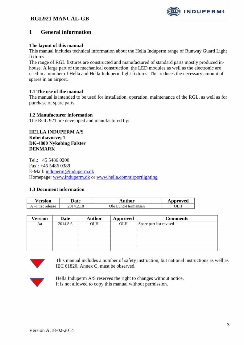
1.3 Document information
Version Date Author Approved A –First release 2014.2.18 Ole Lund-Hermansen OLH
Version Date Author Approved Comments
Aa 2014.8.6 OLH OLH Spare part list revised
This manual includes a number of safety instruction, but national instructions as well as
IEC 61820, Annex C, must be observed.
Hella Induperm A/S reserves the right to changes without notice.
It is not allowed to copy this manual without permission.

RGL921 MANUAL-GB
4
Version A:18-02-2014
2 Overall RGL 921 information
2.1 Relevant standards
The range of RGL 921 High Intensity is constructed, manufactured and tested to meet the
requirements in ICAO annex 14, 5.3.20 for use in configuration A as elevated marking of
Runway/Taxiway intersections. Maximum Average intensity of 3000cd with light distribution
according to ISO candela diagram fig. 2.25 with less than 40W /Light output.
Lightweight construction with no heavy parts above ground level.
2.2 Main data
The RGL 921 light fixtures uses the same technology and main parts as used in unidirectional LED
light fixture type 792 for Approach, Side row, Threshold and End Light.
The RGL 921 light fixtures have a built flasher electronics which automatically synchronizes when
switched on.
Designed to meet all environmental conditions given in FAA AC No. 150/5345-46D for L-804.
Standard height app. 480mm
Standard 100% input current is 6,6A, and the fixtures can be dimmed to 2,8A.
Features:
The outside of the yellow front glasses is smooth and needs no cleaning
Extremely easy levelling and adjustment due to patented ball joint.
No adjustment after change of LED module or electronics.
Only fully, corrosion proof components are used.
Finished in stove enamel aviation yellow, RAL 1028
The high intensity RGL 921 are always supplied with a visor for protection of LED from sunlight
and to maximize contrast between lamp-on and lamp-off states
Two types of breakable couplings available:
Type A for 2” thread
Type C for Ø-2” (60mm) pole mounting
45 flashes per minute per lamp
Shipping details per fixture: 10Kg / 0,1 m3
2.3 RGL 921variants
a. Input
RGL 921 is as mentioned before constructed for nominal 6,6A series circuits, but a special
transformer can be supplied, if a parallel supply (120 or 230VAC) is required.
b. Fail Open relay
The RGL 921 can be supplied with or without a Fail Open relay. The Fail Open relay can be
programmed for customer specified functions.
Each side of the RGL fixture is controlled and monitored individually by the electronics. If a failure
is detected, this will activate the fail-open relay. If the RGL unit is with only one input cable, the Fail
Open relay will switch-off the complete unit and report the error to the system outside by opening the
power supply line. For RGL fixtures with two input cables, two nos. Fail Open relays can be built-in,
and in this case a detected failure will only switch-off the faulty lamp and leave the other side on.
c. Height of fixture.
The RGL 921 light fixture can upon request be quoted in customer specified heights.

RGL921 MANUAL-GB
5
Version A:18-02-2014
d. List of variants.
This Manual is valid for the following RGL 921 variants:
Hella Induperm
Type No.
Hella
Type No.
Type of breakable
coupling included
Fail Open
Relay
included?
Internal
flasher?
Input connector
921.880 8NA 011 575-127 A No Yes FAA –L823-style 1
921.885 8NA 011 575-107 C No Yes FAA –L823-style 1
921.890 8NA 011 575-137 A Yes Yes FAA –L823-style 1
921.895 8NA 011 575-117 C Yes Yes FAA –L823-style 1
921.900 8NA 011 575-147 A No No 2 x FAA –L823-style 1
921.905 8NA 011 575-157 C No No 2 x FAA –L823-style 1
921.910 8NA 011 575-167 A Yes No 2 x FAA –L823-style 1
921.915 8NA 011 575-177 C Yes No 2 x FAA –L823-style 1
2.4 Warranty limitations
The manufacturer or his representative cannot be held responsible for failures and malfunctions, if
the instructions in this manual are not followed.
The RGL 921will meet all specifications when installed and operated as specified.
Hella Induperm A/S only has responsibility to replace faulty parts if construction, production or
component failure is proven.
3 RGL 921 DESCRIPTION
3.1 General Information
Hella Induperm RGL 921 light fixtures are constructed mainly by using standard components from
Hella-Induperm standard program of elevated fittings. Each fitting has two light systems. Each light
system is a unidirectional, yellow light. Each light system can be individual adjusted for toe-in and
elevation.
The fitting has a breakable coupling, designed for 2” (60mm) stake mounting (Type C) or with 2”
thread stub (Type A).
The light fixture is designed for an expected lifetime for the LED´s of 50.000 Hours.
3.2 RGL electronics
The driver electronic for the LED modules are identical to the electronics used in Hella inset lights
and in Hella Induperm elevated unidirectional lights for Approach, Siderow, Threshold, Threshold
Wing bar and for Runway End light.
The electronic will transfer the RMS value of the 6,6A series circuit current into the necessary LED
current. The electronic is informed about the LED current needed from the EPROM memory on the
LED module.
The electronics also have a built-in facility for flashing the LED’s and to automatically synchronize
to the Ac input when switched-on. One of the two light units are programmed to start off and the
other to start on, and the two lights stays synchronized by means of the counting the half waves on
the power supply. The RGL units can be ordered with or without activated internal flasher.
3.3 Light output performance
Three parameters are essential for the correct light output.
The color of the LED output together with the yellow front glass defines the correct color.
The LED light output together with the lens on each LED defines the correct light distribution.
RGL921 MANUAL-GB
6
Version A:18-02-2014
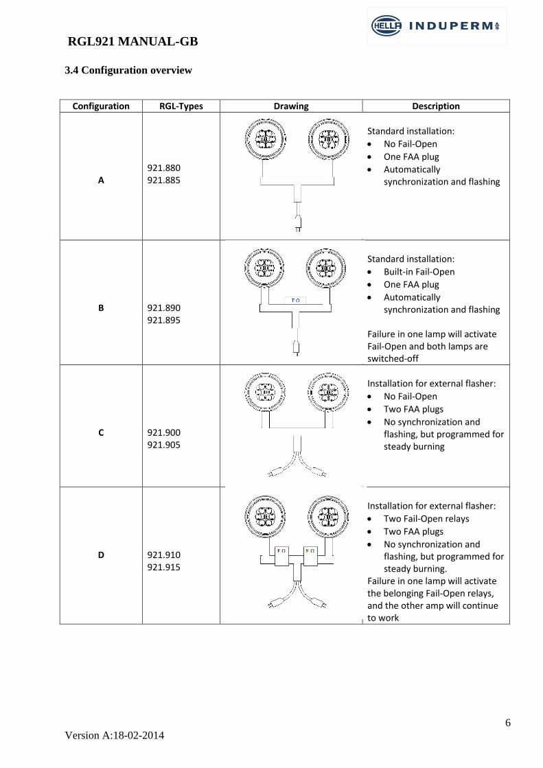
3.4 Configuration overview
Configuration RGL-Types Drawing Description
A
921.880 921.885
Standard installation:
No Fail-Open
One FAA plug
Automatically synchronization and flashing
B
921.890 921.895
Standard installation:
Built-in Fail-Open
One FAA plug
Automatically synchronization and flashing
Failure in one lamp will activate Fail-Open and both lamps are switched-off
C
921.900 921.905
Installation for external flasher:
No Fail-Open
Two FAA plugs
No synchronization and flashing, but programmed for steady burning
D
921.910 921.915
Installation for external flasher:
Two Fail-Open relays
Two FAA plugs
No synchronization and flashing, but programmed for steady burning.
Failure in one lamp will activate the belonging Fail-Open relays, and the other amp will continue to work
RGL921 MANUAL-GB
7
Version A:18-02-2014
4 RGL installation
4.1 Unpacking the RGL fixtures
The RGL units are supplied in individual boxes.
Please make sure that nothing is broken before starting installation.
As standard, the RGL light fixtures are not pre-adjusted in the factory and must be adjusted before
taken into operation.
4.2 Theoretical installation consideration
As standard, the two light fixtures on the same pylon are adjusted identical, that is with parallel light
output. On complicated intersections with f. i. more taxiways, other ways of adjustment might be
used.
Vertical adjustment:
With a main Beam coverage of ± 4°, the Main beam coverage will be down to 0 ° with a vertical
adjustment to 4°. With this adjustment, the Main Beam will cover from ground level and 14 m up in
a distance of 100m. This might be too little, and we suggest a coverage form 1,2m above ground
(corresponding to a person sitting in a vehicle) in a distance of 50 m, corresponding to a beam
elevation of 5,2°, which again will give a Main beam coverage from 2,4 m above ground and up to
16,2 m in a distance of 100 m.
Toe-in:
If we aim the light direction to a point in the middle of the taxiway in a distance of 100 m, this will
correspond to a Toe-in of 12°, and give a Main Beam coverage 160 m out and to a point 70 m from
the RGL line.
Conclusion:
We recommend to adjust the light fixtures with a vertical elevation of 5,2°, and a Toe-in of 12°.
4.3 Before the installation
To simplify installation the light fixtures can be pre-adjusted in the workshop, as follows:
The two light units are adjusted to have parallel light output perpendicular to the pylon, and with a
vertical setting of 5,2°.
4.4 Installation in the field
The pre-adjusted light fixture is electrical connected and mounted in the breakable coupling without
tightening the screws in the breakable coupling. The pylon is turned until it is perpenticulat to a line
towards a point in the middle of the taxiway, 100 m away from the RGL line. The screws in the
breakable coupling are tightened.
5 Maintenance
5.1 In the field
Every 6 month:
The elevation and Toe-in adjustments are controlled
How to mount the adjustment tool:
Regularly:
Front glass is cleaned if necessary, and a visual control of similar light output from both light units.
RGL921 MANUAL-GB
8
Version A:18-02-2014
5.2 In the workshop
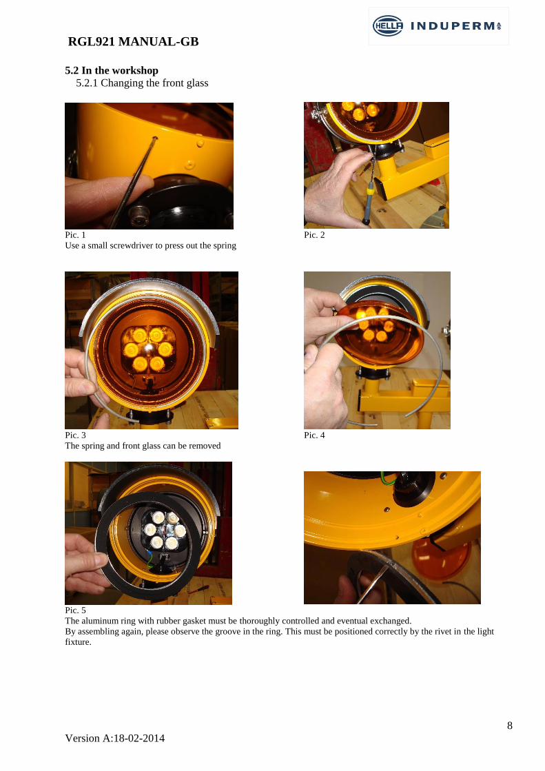
5.2.1 Changing the front glass
Pic. 1 Pic. 2
Use a small screwdriver to press out the spring
Pic. 3 Pic. 4
The spring and front glass can be removed
Pic. 5
The aluminum ring with rubber gasket must be thoroughly controlled and eventual exchanged.
By assembling again, please observe the groove in the ring. This must be positioned correctly by the rivet in the light
fixture.
RGL921 MANUAL-GB
9
Version A:18-02-2014
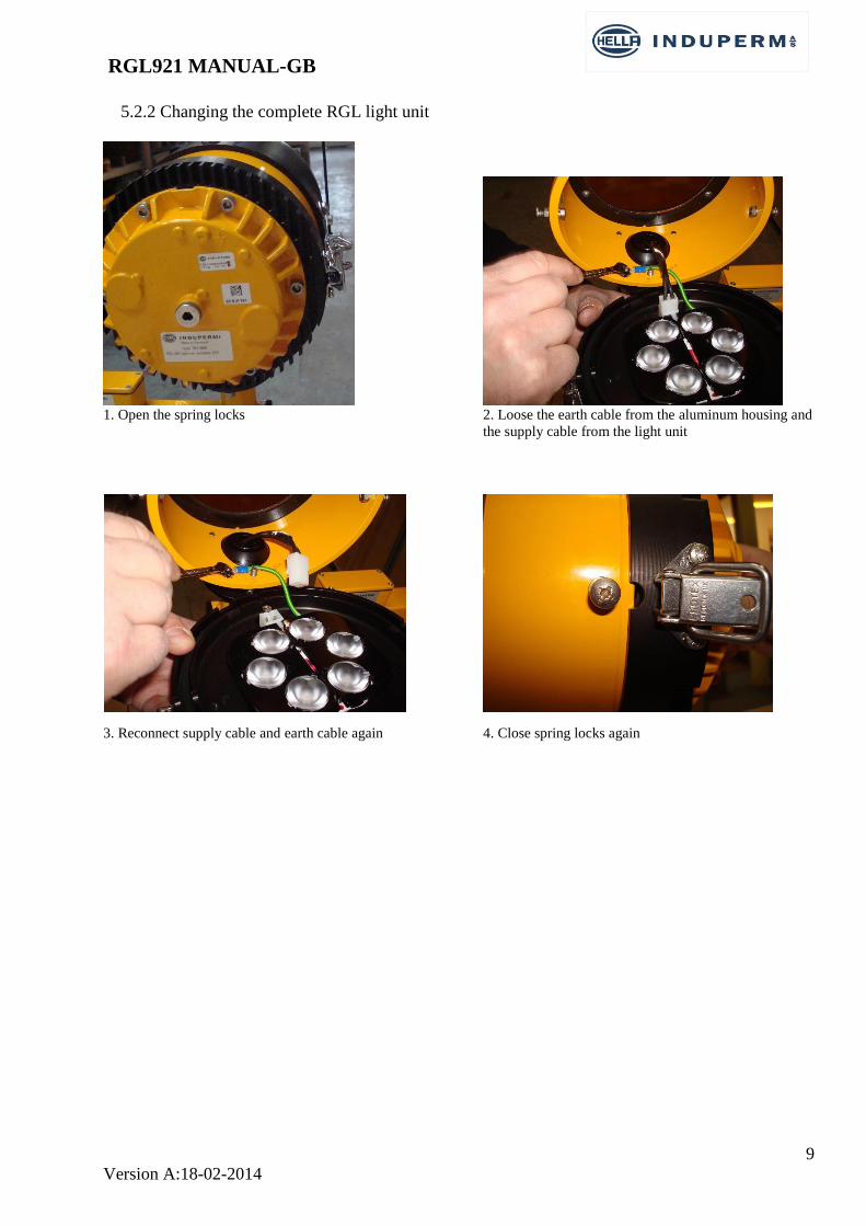
5.2.2 Changing the complete RGL light unit
1. Open the spring locks 2. Loose the earth cable from the aluminum housing and
the supply cable from the light unit
3. Reconnect supply cable and earth cable again 4. Close spring locks again
RGL921 MANUAL-GB
10
Version A:18-02-2014
6 Specifications
Light output according to ICAO Annex 14, Figure A2-25 (see enclosed Certificate)
100% current 6,6A, power consumption app. 50W
Expected LED lifetime of 50.000 H
Standard overall height app. 480mm. Other heights upon request.
Weight app. 8 KG
Ingress Protection IP 54
Supplied with breakable coupling type A (2” Thread) or C (60mm tube)
Connection with one or two FAA plugs Style 1
Finished in stove enamel aviation yellow RAL 1028
Supplied with visor for sunlight protection of LED’s
Can be supplied with Fail-Open Relay (or relays)
Can be supplied with base plate (optional)
The fixture will as standard be supplied pre-adjusted for parallel light output from the two
light systems, both adjusted to an elevation of 5,25°
The fixtures can be adjusted with tool type 792.117, pre-adjusted for 5,2° elevation.

RGL921 MANUAL-GB
11
Version A:18-02-2014
7 List of spares
7.1 Assembling drawing

RGL921 MANUAL-GB
12
Version A:18-02-2014
7.2 List of components, see drwg. 7.1

RGL921 MANUAL-GB
13
Version A:18-02-2014
8 Certificate