Embed Size (px)
Citation preview

Gas Well Deliquification WorkshopAdams Mark Hotel, Denver, Colorado
February 25 - 27, 2008
Rule-of-Thumb Calculation of Key Events During the Plunger Lift Cycle
James F. Lea, PLTech LLCO. Lynn Rowlan, Echometer Company

Feb. 25 - 27, 2008 2008 Gas Well Deliquification Workshop Denver, Colorado
2
1.1. Plunger Lift Operation CyclePlunger Lift Operation Cycle2.2. Minimum Plunger Lift RequirementsMinimum Plunger Lift Requirements3.3. Load Factor Determines if Plunger will Load Factor Determines if Plunger will
SurfaceSurface4.4. Amount & Height of Liquid in TubingAmount & Height of Liquid in Tubing5.5. Minimum ShutMinimum Shut--in Timein Time6.6. Plunger Rise Velocity and Maximum Plunger Rise Velocity and Maximum
Unloading TimeUnloading Time7.7. Plunger Efficiency and Maximum Plunger Efficiency and Maximum AfterflowAfterflow
TimeTime
IntroductionIntroduction

Feb. 25 - 27, 2008 2008 Gas Well Deliquification Workshop Denver, Colorado
3
[A][A] Valve Opens, Valve Opens, Unloading Unloading BeginsBegins
1.1. Liquid Arrives, Liquid Arrives, Tubing Pres. at Tubing Pres. at Minimum Minimum
2.2. Plunger Plunger Arrives, AfterArrives, After--flow begins flow begins Tubing Tubing Pressure SpikePressure Spike
Cycle for Example WellCycle for Example Well[A][A] 11 22 [B][B] 3 43 4 [C][C]
Casing PressureAcoustic Signal
Tubing Pressure
[B][B] Valve Closes, Valve Closes, ShutShut--in Begins in Begins and Tubing and Tubing Pressure Starts Pressure Starts IncreasingIncreasing
3.3. Plunger hits Plunger hits LiquidLiquid
4.4. Plunger on Plunger on BottomBottom
[C][C] Valve Opens, Valve Opens, Unloading Unloading BeginsBegins
14.13
72.34
68.12
Elapsed Time - Minutes
Feb. 25 - 27, 2008 2008 Gas Well Deliquification Workshop Denver, Colorado
4
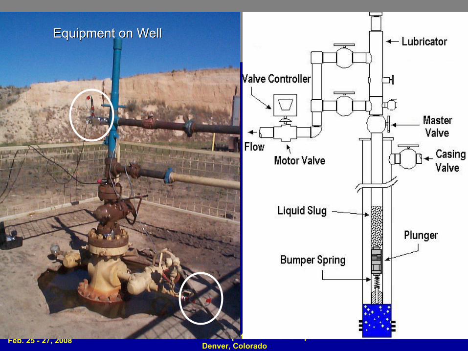
Equipment on WellEquipment on Well

Feb. 25 - 27, 2008 2008 Gas Well Deliquification Workshop Denver, Colorado
5
Example Output from RulesExample Output from Rules--ofof--Thumb XLS:Thumb XLS:
Initial Conditions:Initial Conditions:ShutShut--in 68:12in 68:12Unloading 14:13 MinUnloading 14:13 MinAfterAfter--Flow 72:34 MinFlow 72:34 Min
Need to Change:Need to Change:Increase AfterIncrease After--FlowFlowReduce ShutReduce Shut--inin

Feb. 25 - 27, 2008 2008 Gas Well Deliquification Workshop Denver, Colorado
6
Plunger Lift RulePlunger Lift Rule--ofof--Thumb Inputs:Thumb Inputs:
Feb. 25 - 27, 2008 2008 Gas Well Deliquification Workshop Denver, Colorado
7
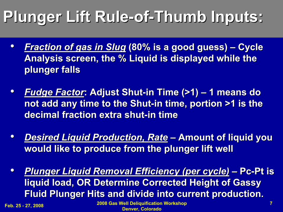
•• Fraction of gas in SlugFraction of gas in Slug (80% is a good guess) (80% is a good guess) –– Cycle Cycle Analysis screen, the % Liquid is displayed while the Analysis screen, the % Liquid is displayed while the plunger falls plunger falls
•• Fudge FactorFudge Factor: Adjust Shut: Adjust Shut--in Time (>1) in Time (>1) –– 1 means do 1 means do not add any time to the Shutnot add any time to the Shut--in time, portion >1 is the in time, portion >1 is the decimal fraction extra shutdecimal fraction extra shut--in timein time
•• Desired Liquid Production, RateDesired Liquid Production, Rate –– Amount of liquid you Amount of liquid you would like to produce from the plunger lift well would like to produce from the plunger lift well
•• Plunger Liquid Removal Efficiency (per cycle)Plunger Liquid Removal Efficiency (per cycle) –– PcPc--Pt is Pt is liquid load, OR Determine Corrected Height of Gassy liquid load, OR Determine Corrected Height of Gassy Fluid Plunger Hits and divide into current production.Fluid Plunger Hits and divide into current production.
Plunger Lift RulePlunger Lift Rule--ofof--Thumb Inputs:Thumb Inputs:

Feb. 25 - 27, 2008 2008 Gas Well Deliquification Workshop Denver, Colorado
8
1.1. Volume of Liquid in the tubing = Volume of Liquid in the tubing = .00224176 (Pcasing.00224176 (Pcasing--Ptubing) (Tbg ID_^2 )/ SpGr of LiquidPtubing) (Tbg ID_^2 )/ SpGr of Liquid
Where .002241 = Where .002241 = =1/ 0.433 * (3.14 /(4*144)) *(1/5.615)=1/ 0.433 * (3.14 /(4*144)) *(1/5.615)
2.2. Height of Gassy Liquid Height of Gassy Liquid –– ftft=(Pcsg=(Pcsg--Ptubing)/ (.433 * SpGr * (1Ptubing)/ (.433 * SpGr * (1--Gas Fraction))Gas Fraction))
3.3. Fall time through gas during ShutFall time through gas during Shut--in Periodin Period=(depth=(depth--height of gassy fluid) / FPM in gas of plungerheight of gassy fluid) / FPM in gas of plunger
4.4. Fall time through gassy liquid during ShutFall time through gassy liquid during Shut--in Periodin Period= height of gassy fluid / fpm of plunger in gassy fluid= height of gassy fluid / fpm of plunger in gassy fluid
5.5. Total fall time + Minimum ShutTotal fall time + Minimum Shut--in Time in Time = 3+4 above= 3+4 above
Plunger Lift RulePlunger Lift Rule--ofof--Thumb Calculations:Thumb Calculations:

Feb. 25 - 27, 2008 2008 Gas Well Deliquification Workshop Denver, Colorado
9
6.6. Total Fall Time x Fudge Factor Total Fall Time x Fudge Factor –– Time for ShutTime for Shut--in Periodin Period=fall time through gas and liquid x Fudge Factor=fall time through gas and liquid x Fudge Factor
7.7. Min CP Required for Casing Pressure Unload LiquidMin CP Required for Casing Pressure Unload Liquid= highest of 2 x LP or 2(Pc= highest of 2 x LP or 2(Pc--Ptbg) + LPPtbg) + LP
8.8. Minimum Plunger Arrival Time (>=1000 Ft/Min)Minimum Plunger Arrival Time (>=1000 Ft/Min)=depth/1000=depth/1000
9.9. Maximum Plunger Arrival Time (<=500 Ft/Min)Maximum Plunger Arrival Time (<=500 Ft/Min)= depth/500= depth/500
10.10. # Cycles/Day to Remove Desired Liquid # Cycles/Day to Remove Desired Liquid = bpd= bpd--liquid / plunger removal efficiency / bbls in tubingliquid / plunger removal efficiency / bbls in tubing
Plunger Lift RulePlunger Lift Rule--ofof--Thumb Calculations:Thumb Calculations:

Feb. 25 - 27, 2008 2008 Gas Well Deliquification Workshop Denver, Colorado
10
11.11. Maximum # Cycles/Day Possible Using Above TimesMaximum # Cycles/Day Possible Using Above Times=24 * 60 / ( total fall time x FF + slowest arrival time)=24 * 60 / ( total fall time x FF + slowest arrival time)
12.12. Maximum Possible Liquid Production Rate (Based on # Maximum Possible Liquid Production Rate (Based on # Cycles)Cycles)= (plgr removal effcy) ( bbls in tubing) (max cycles day)= (plgr removal effcy) ( bbls in tubing) (max cycles day)
13.13. Minutes per cycleMinutes per cycle= CPD < max CPD then 60x24/ CPD from 10= CPD < max CPD then 60x24/ CPD from 10if not then total fall time x fudge + slowest arrival timeif not then total fall time x fudge + slowest arrival time
14.14. Maximum Unloading Time, Min.. Maximum Unloading Time, Min.. =Slowest arrival time=Slowest arrival time
Plunger Lift RulePlunger Lift Rule--ofof--Thumb Calculations:Thumb Calculations:
Feb. 25 - 27, 2008 2008 Gas Well Deliquification Workshop Denver, Colorado
11
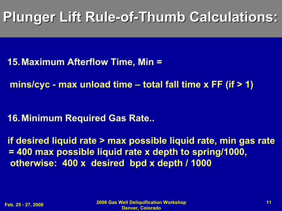
15.15. Maximum Maximum AfterflowAfterflow Time, Min = Time, Min =
mins/cycmins/cyc -- max unload time max unload time –– total fall time x FF (if > 1)total fall time x FF (if > 1)
16.16. Minimum Required Gas Rate..Minimum Required Gas Rate..
if desired liquid rate > max possible liquid rate, min gas if desired liquid rate > max possible liquid rate, min gas rate rate = 400 max possible liquid rate x depth to spring/1000, = 400 max possible liquid rate x depth to spring/1000, otherwise: 400 x desired bpd x depth / 1000otherwise: 400 x desired bpd x depth / 1000
Plunger Lift RulePlunger Lift Rule--ofof--Thumb Calculations:Thumb Calculations:
Feb. 25 - 27, 2008 2008 Gas Well Deliquification Workshop Denver, Colorado
12
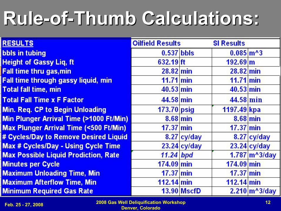
RuleRule--ofof--Thumb Calculations:Thumb Calculations:

Feb. 25 - 27, 2008 2008 Gas Well Deliquification Workshop Denver, Colorado
13
Fraction of gas in Fraction of gas in Liquid Slug (80% Liquid Slug (80% is a good guess)is a good guess)
S-CurveIs used to
Determine the Gaseous Liquid Loaded Column
Gradient Below
Liquid Level
Qg < QcVSL = 0
SS--CurveCurveIs used to Is used to
Determine the Determine the Gaseous Liquid Gaseous Liquid Loaded Column Loaded Column
Gradient Gradient BelowBelow
Liquid LevelLiquid Level
QgQg < Qc< QcVVSLSL = 0= 0
~ 20% Liquid ~ 20% Liquid Actual Field Actual Field Collected Data Collected Data PointsPoints
VVSLSL = 0= 0LoadedLoadedQgQg < Qc< Qc
~ 0.08 psi/ft
~0.433 ~0.433 psipsi/ft/ft
Feb. 25 - 27, 2008 2008 Gas Well Deliquification Workshop Denver, Colorado
14
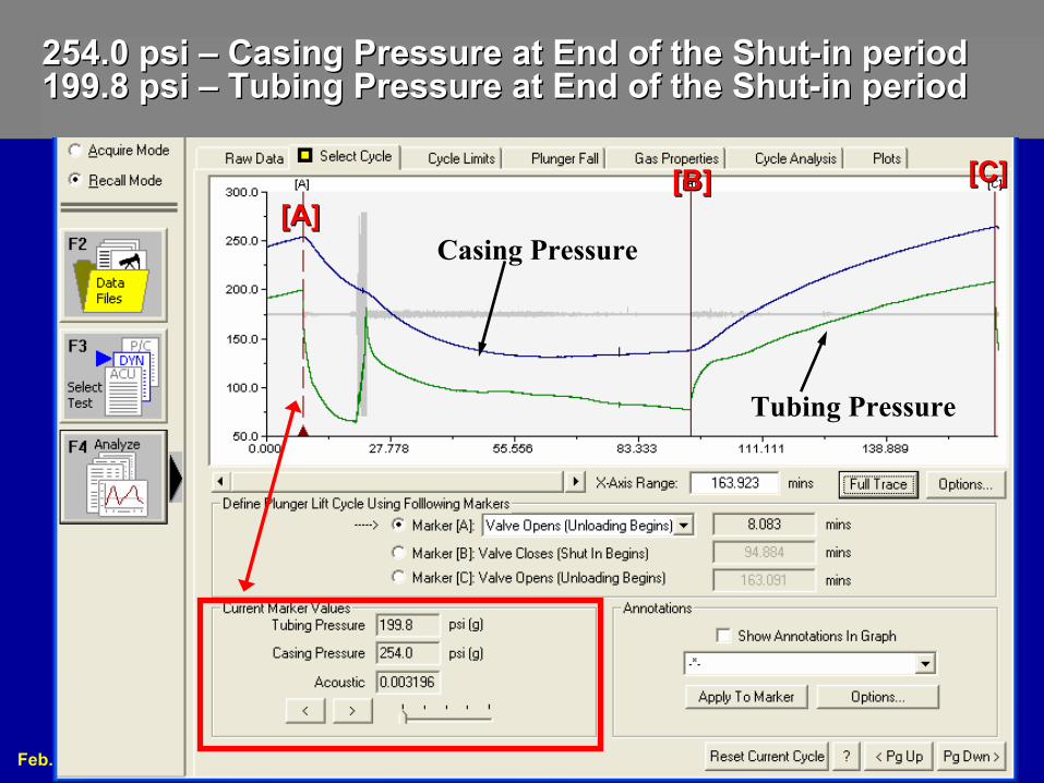
254.0 psi 254.0 psi –– Casing Pressure at End of the ShutCasing Pressure at End of the Shut--in period in period 199.8 psi 199.8 psi –– Tubing Pressure at End of the ShutTubing Pressure at End of the Shut--in periodin period
[A][A][B][B] [C][C]
Casing Pressure
Tubing Pressure
Feb. 25 - 27, 2008 2008 Gas Well Deliquification Workshop Denver, Colorado
15
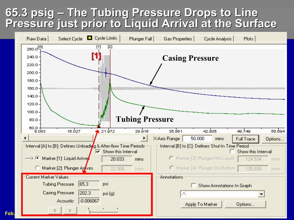
65.3 psig 65.3 psig –– The Tubing Pressure Drops to Line The Tubing Pressure Drops to Line Pressure just prior to Liquid Arrival at the SurfacePressure just prior to Liquid Arrival at the Surface
[1][1] Casing Pressure
Tubing Pressure

Feb. 25 - 27, 2008 2008 Gas Well Deliquification Workshop Denver, Colorado
16
Average Plunger Fall Velocity in Gas:Average Plunger Fall Velocity in Gas: 279.4 ft/min 279.4 ft/min Average Plunger Fall Velocity in Liquid: 54.3 ft/minAverage Plunger Fall Velocity in Liquid: 54.3 ft/min
Looking at this MinuteLooking at this Minute
AverageAverageFall VelFall Vel
Each JointEach Joint
Falling through GasFalling through Gas

Feb. 25 - 27, 2008 2008 Gas Well Deliquification Workshop Denver, Colorado
17
Plunger Lift: Will it Work (Load Factor)Plunger Lift: Will it Work (Load Factor)
Load Factor: Load Factor: (Pcas (Pcas –– Ptub) /Ptub) /(Pcas (Pcas –– Pline) < 50%Pline) < 50%
(254.0 (254.0 –– 199.8) /199.8) /(254.0 (254.0 -- 65.3) = 28.7%65.3) = 28.7%
Casing Casing PressurePressure can can NOT be less than NOT be less than Tubing Tubing PressurePressure, OR , OR Plunger Stops Plunger Stops Coming to the SurfaceComing to the Surface
Pcas = 254.0Pcas = 254.0
Ptub = 199.8Ptub = 199.8
Ptub = 65.3Ptub = 65.3

Feb. 25 - 27, 2008 2008 Gas Well Deliquification Workshop Denver, Colorado
1850.0
100.0
150.0
200.0
250.0
300.0
49.604 56.549 63.493 70.438 77.382
[A] [B][1] [2]
60.0
80.0
100.0
120.0
140.0
160.0
180.0
200.0
220.0
240.0
260.0
280.0
94.884 108.773 122.662 136.551 150.440
[B] [C][3] [4]
ShutShut--in Periodin Period
Note: After Reducing ShutNote: After Reducing Shut--in Time Period Based on in Time Period Based on Minimum Fall Time Minimum Fall Time
33 Minute Shut33 Minute Shut--in Time Periodin Time Period241Mscf/D. with 8 bbls of oil and 4 bbls of water241Mscf/D. with 8 bbls of oil and 4 bbls of water
68 Minute Shut68 Minute Shut--in Time Periodin Time Period168 168 MscfMscf/D with 6 bbls of oil and 3 bbls of water/D with 6 bbls of oil and 3 bbls of water
Initial ConditionsInitial Conditions
Final ConditionsFinal Conditions

Feb. 25 - 27, 2008 2008 Gas Well Deliquification Workshop Denver, Colorado
19
1.1. Calculations assist Plunger Lift SetupCalculations assist Plunger Lift Setup2.2. Calculated timings of plunger lift cycle Calculated timings of plunger lift cycle
compared to measurements acquired at the wellcompared to measurements acquired at the well3.3. Check Calculations Using Measured DataCheck Calculations Using Measured Data4.4. Calculation Guide the operator to effectively Calculation Guide the operator to effectively
analyze installation analyze installation 5.5. Adjust and optimize the plunger lift installation.Adjust and optimize the plunger lift installation.6.6. Increase Gas Production by Reducing Liquid Increase Gas Production by Reducing Liquid
LoadingLoading7.7. Reduce Equipment Damage and FailuresReduce Equipment Damage and Failures
RulesRules--ofof--Thumb Calculator:Thumb Calculator:Provide XLS spreadsheet to industry to easily calculate setup Parameters for controller and make adjustments to optimize Plunger Lift Installation

Feb. 25 - 27, 2008 2008 Gas Well Deliquification Workshop Denver, Colorado
20
Plunger Rise Velocity Plunger Rise Velocity For RuleFor Rule--ofof--Thumb Spreadsheet Example Calculations Used Thumb Spreadsheet Example Calculations Used ““Optimize BeforeOptimize Before”” WellWell
EXCEL Spreadsheets available from Echometer Co. or PLTech LLC:1) ConventionalPlungerLift_Rules-ofThumb_CalculatorPRO.xls2) Foss and Gaul Original and Modified_PlungerRiseVelocity.xls
Feb. 25 - 27, 2008 2008 Gas Well Deliquification Workshop Denver, Colorado
21
CopyrightRights to this presentation are owned by the company(ies) and/or author(s) listed on the title page. By submitting this presentation to the Gas Well Deliquification Workshop, they grant to the Workshop, the Artificial Lift Research and Development Council (ALRDC), and the Southwestern Petroleum Short Course (SWPSC), rights to:
– Display the presentation at the Workshop.– Place it on the www.alrdc.com web site, with access to the site to be
as directed by the Workshop Steering Committee.– Place it on a CD for distribution and/or sale as directed by the
Workshop Steering Committee.Other uses of this presentation are prohibited without the expressed written permission of the company(ies) and/or author(s) who own it and the Workshop Steering Committee.
Feb. 25 - 27, 2008 2008 Gas Well Deliquification Workshop Denver, Colorado
22
DisclaimerThe following disclaimer shall be included as the last page of a Technical Presentation or Continuing Education Course. A similar disclaimer is included on the front page of the Gas Well Deliquification Web Site.The Artificial Lift Research and Development Council and its officers and trustees, and the Gas Well Deliquification Workshop Steering Committee members, and their supporting organizations and companies (here-in-after referred to as the Sponsoring Organizations), and the author(s) of this Technical Presentation or Continuing Education Training Course and their company(ies), provide this presentation and/or training material at the Gas Well Deliquification Workshop "as is" without any warranty of any kind, express or implied, as to the accuracy of the information or the products or services referred to by any presenter (in so far as such warranties may be excluded under any relevant law) and these members and their companies will not be liable for unlawful actions and any losses or damage that may result from use of any presentation as a consequence of any inaccuracies in, or any omission from, the information which therein may be contained.The views, opinions, and conclusions expressed in these presentations and/or training materials are those of the author and not necessarily those of the Sponsoring Organizations. The author is solely responsible for the content of the materials.The Sponsoring Organizations cannot and do not warrant the accuracy of these documents beyond the source documents, although we do make every attempt to work from authoritative sources. The Sponsoring Organizations provide these presentations and/or training materials as a service. The Sponsoring Organizations make no representations or warranties, express or implied, with respect to the presentations and/or training materials, or any part thereof, including any warrantees of title, non-infringement of copyright or patent rights of others, merchantability, or fitness or suitability for any purpose.