Embed Size (px)
Citation preview

Analyzing &
Troubleshooting
Plunger Lifted Wells
Rick Nadkrynechny
PSI
Pressure Drop =
Weight / Area
Plunger weight (8 lbs) / Area of 2-3/8”
Area
Pressure Drop =
2.4 psi
When Shut-in Begins the Tubing Pressure Drops
as Plunger Starts to Fall
Pressure
Drop
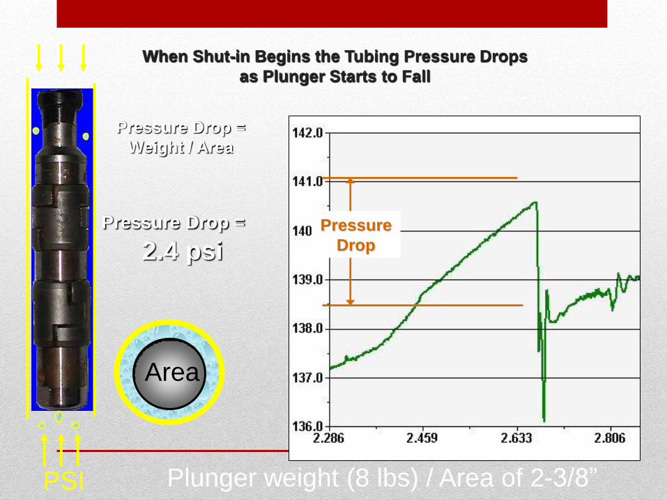
Pressure Drop =
Weight / Area
Plunger weight (8 lbs) / Area of 2-3/8”
When Shut-in Begins the Tubing Pressure Instantly Drops
when Plunger Starts to Fall
Pressure
Drop
Pressure
Drop
Tubing Held Weight
Released from Catcher Weight Supported
by Flowing Gas
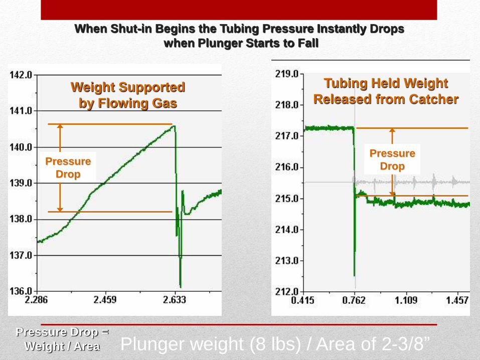
Sometimes Easier to See Plunger Fall through Liquid by Examining
the Tubing Pressure Signal
Hits Liquid
Pressure Kicks as Plunger Falls through Liquid
Tubing Pressure Increases when Plunger Stops
Adjustable By-Pass Plunger Usually See Collars in Liquid
when Pressure is High.
0.4
Psi
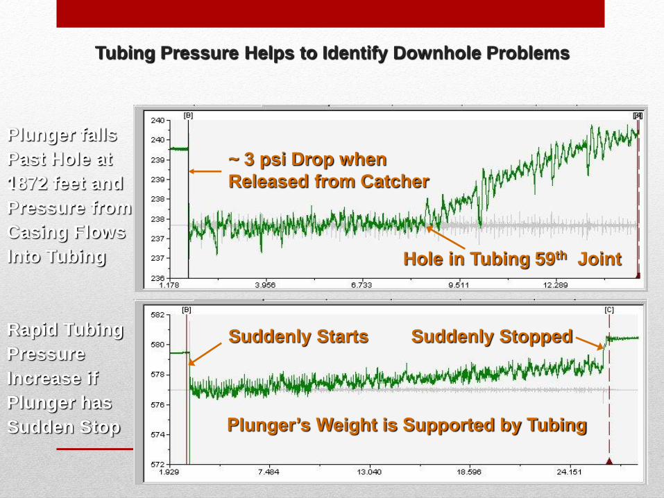
Tubing Pressure Helps to Identify Downhole Problems
Plunger falls
Past Hole at
1872 feet and
Pressure from
Casing Flows
Into Tubing
Rapid Tubing
Pressure
Increase if
Plunger has
Sudden Stop
Hole in Tubing 59th Joint
~ 3 psi Drop when
Released from Catcher
Suddenly Stopped Suddenly Starts
Plunger’s Weight is Supported by Tubing
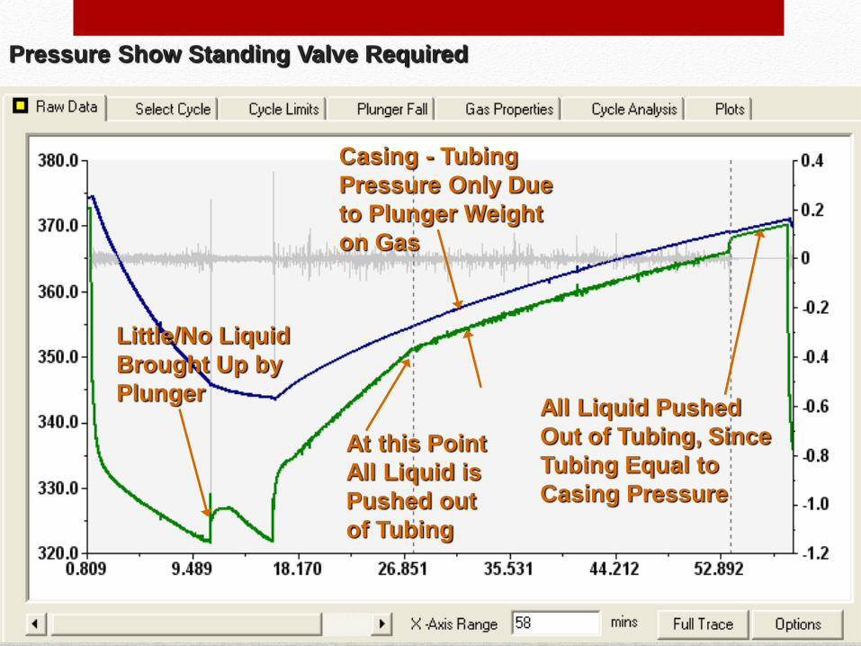
Pressure Show Standing Valve Required
Little/No Liquid
Brought Up by
Plunger
Casing - Tubing
Pressure Only Due
to Plunger Weight
on Gas
At this Point
All Liquid is
Pushed out
of Tubing
All Liquid Pushed
Out of Tubing, Since
Tubing Equal to
Casing Pressure
50.0
60.0
70.0
80.0
90.0
100.0
110.0
120.0
-0.8
-0.6
-0.4
-0.2
0
0.2
0.4
0.6
0.000 55.556 111.111 166.667
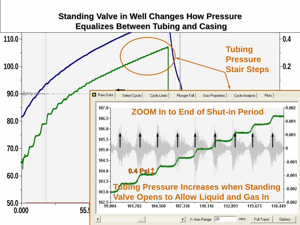
Standing Valve in Well Changes How Pressure
Equalizes Between Tubing and Casing
Tubing Pressure Increases when Standing
Valve Opens to Allow Liquid and Gas In
0.4 Psi
ZOOM In to End of Shut-in Period
Tubing
Pressure
Stair Steps
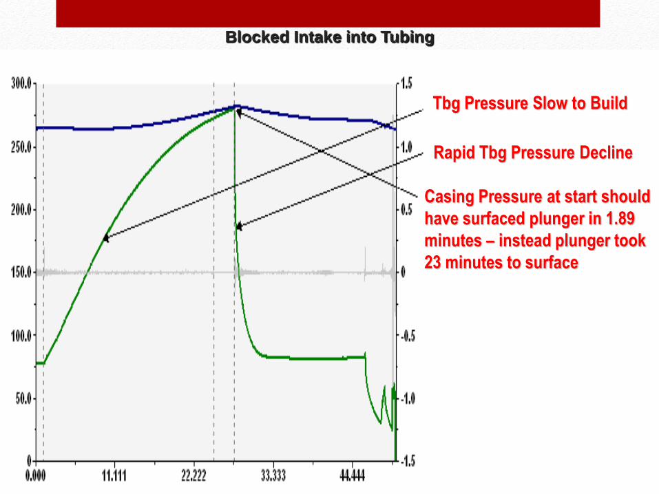
Blocked Intake into Tubing
Tbg Pressure Slow to Build
Rapid Tbg Pressure Decline
Casing Pressure at start should
have surfaced plunger in 1.89
minutes – instead plunger took
23 minutes to surface
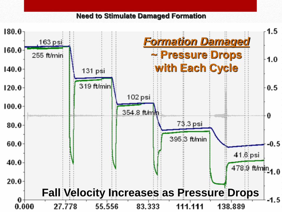
Need to Stimulate Damaged Formation
Formation Damaged
~ Pressure Drops
with Each Cycle
Fall Velocity Increases as Pressure Drops
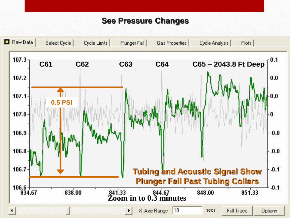
See Pressure Changes
C64 C65 – 2043.8 Ft Deep
0.5 PSI
Tubing and Acoustic Signal Show
Plunger Fall Past Tubing Collars
Zoom in to 0.3 minutes
C63 C62 C61
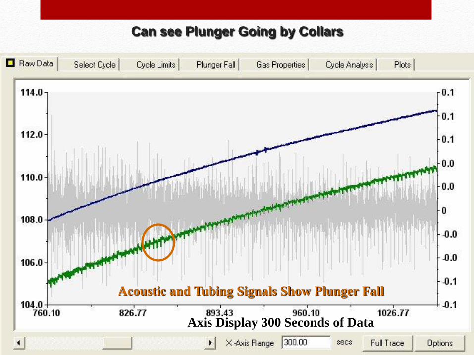
Can see Plunger Going by Collars
Acoustic and Tubing Signals Show Plunger Fall
Axis Display 300 Seconds of Data
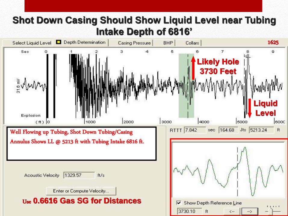
Shot Down Casing Should Show Liquid Level near Tubing
Intake Depth of 6816’
Likely Hole
3730 Feet
Use 0.6616 Gas SG for Distances
Liquid
Level
Well Flowing up Tubing, Shot Down Tubing/Casing Annulus Shows LL @ 5213 ft with Tubing Intake 6816 ft.
1625
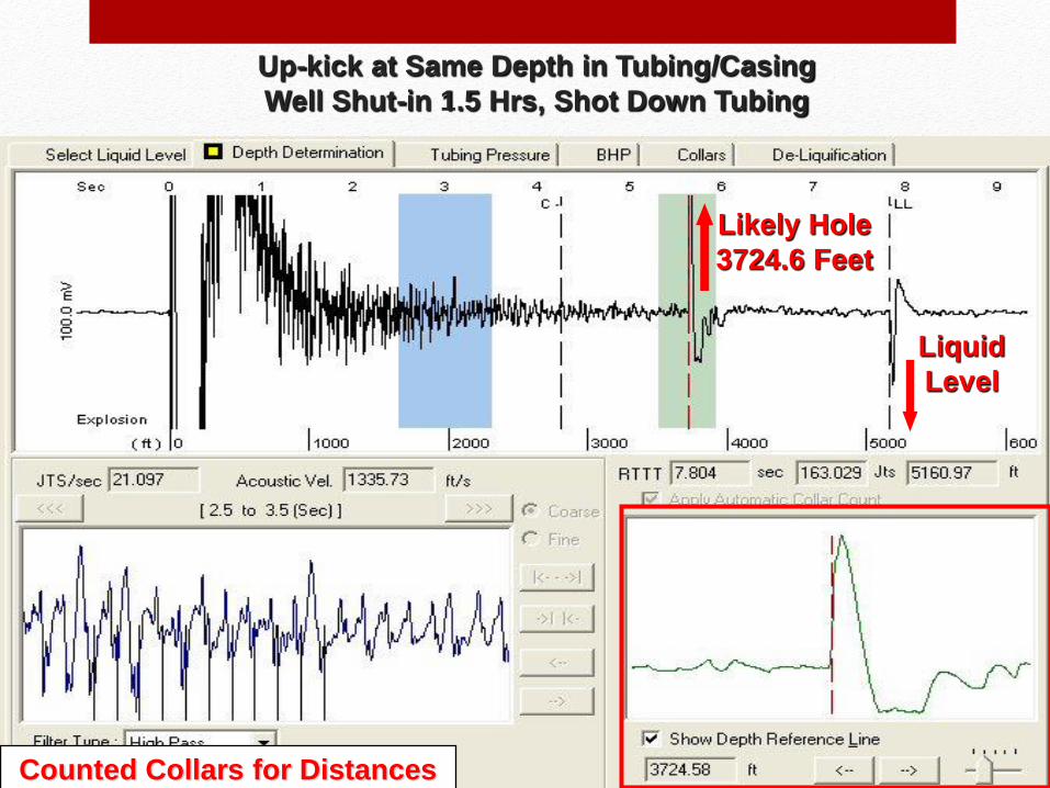
Up-kick at Same Depth in Tubing/Casing
Well Shut-in 1.5 Hrs, Shot Down Tubing
Likely Hole
3724.6 Feet
Counted Collars for Distances
Liquid
Level
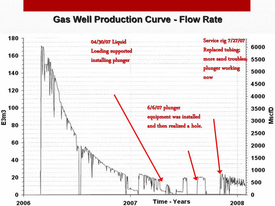
Gas Well Production Curve - Flow Rate
Service rig 7/27/07 Replaced tubing; more sand troubles; plunger working now
6/6/07 plunger equipment was installed and then realized a hole.
04/30/07 Liquid Loading supported installing plunger
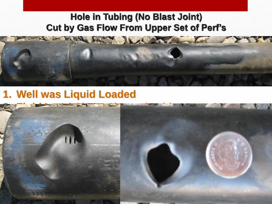
1. Well was Liquid Loaded
2. Fluid Level Shots Showed Tubing was OK
3. Installed plunger and couldn’t surface the plunger
4. Took more tbg shot’s.
5. Then the upkick showed up in the tbg as the well
was shut in for a while.
6. Original shot’s did not expose the hole in the tbg
as the well was loaded up with Gassy Liquid
Above Hole
Hole in Tubing (No Blast Joint)
Cut by Gas Flow From Upper Set of Perf’s
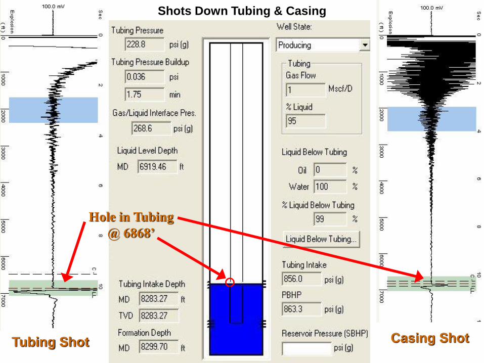
Shots Down Tubing & Casing
Hole in Tubing
@ 6868’
Tubing Shot Casing Shot
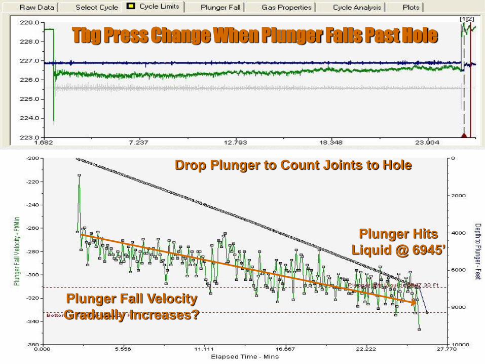
Tbg Press Change When Plunger Falls Past Hole
Plunger Hits
Liquid @ 6945’
Plunger Fall Velocity
Gradually Increases?
Drop Plunger to Count Joints to Hole
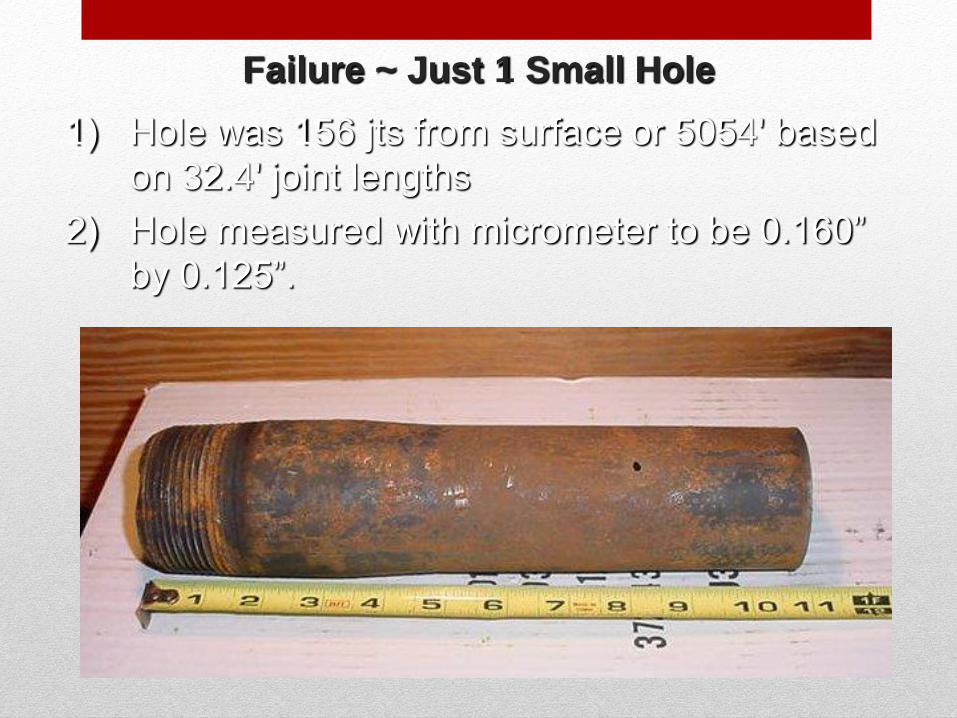
Failure ~ Just 1 Small Hole
1) Hole was 156 jts from surface or 5054' based
on 32.4' joint lengths
2) Hole measured with micrometer to be 0.160”
by 0.125”.
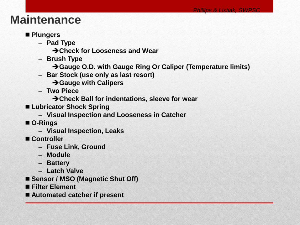
Maintenance Plungers
– Pad Type
Check for Looseness and Wear
– Brush Type
Gauge O.D. with Gauge Ring Or Caliper (Temperature limits)
– Bar Stock (use only as last resort)
Gauge with Calipers
– Two Piece
Check Ball for indentations, sleeve for wear
Lubricator Shock Spring
– Visual Inspection and Looseness in Catcher
O-Rings
– Visual Inspection, Leaks
Controller
– Fuse Link, Ground
– Module
– Battery
– Latch Valve
Sensor / MSO (Magnetic Shut Off)
Filter Element
Automated catcher if present
Phillips & Listiak, SWPSC
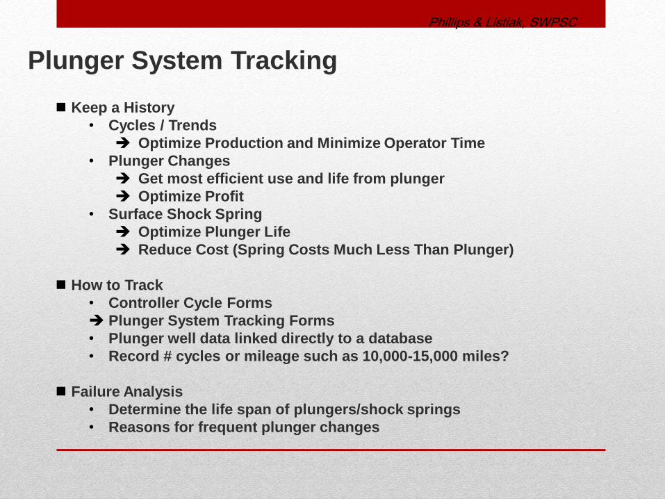
Keep a History
• Cycles / Trends
Optimize Production and Minimize Operator Time
• Plunger Changes
Get most efficient use and life from plunger
Optimize Profit
• Surface Shock Spring
Optimize Plunger Life
Reduce Cost (Spring Costs Much Less Than Plunger)
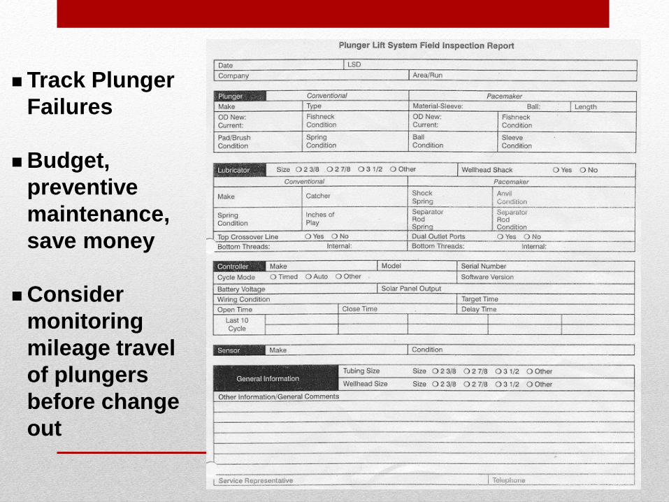
How to Track
• Controller Cycle Forms
Plunger System Tracking Forms
• Plunger well data linked directly to a database
• Record # cycles or mileage such as 10,000-15,000 miles?
Failure Analysis
• Determine the life span of plungers/shock springs
• Reasons for frequent plunger changes
Plunger System Tracking
Phillips & Listiak, SWPSC
Track Plunger
Failures
Budget,
preventive
maintenance,
save money
Consider
monitoring
mileage travel
of plungers
before change
out
Do you want a Standing Valve?
• On every well
• Any time the tubing and casing pressure get closer together
during shut-in
• Do NOT notch, cut a little scratch
• Use SV with spring, so that you can add pressure and push it
out
Do you want to use surfactant with plunger?
Surfactant foam can lift sand and sand can stick plunger.
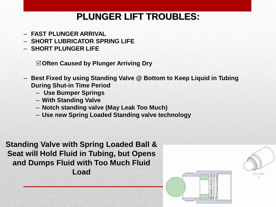
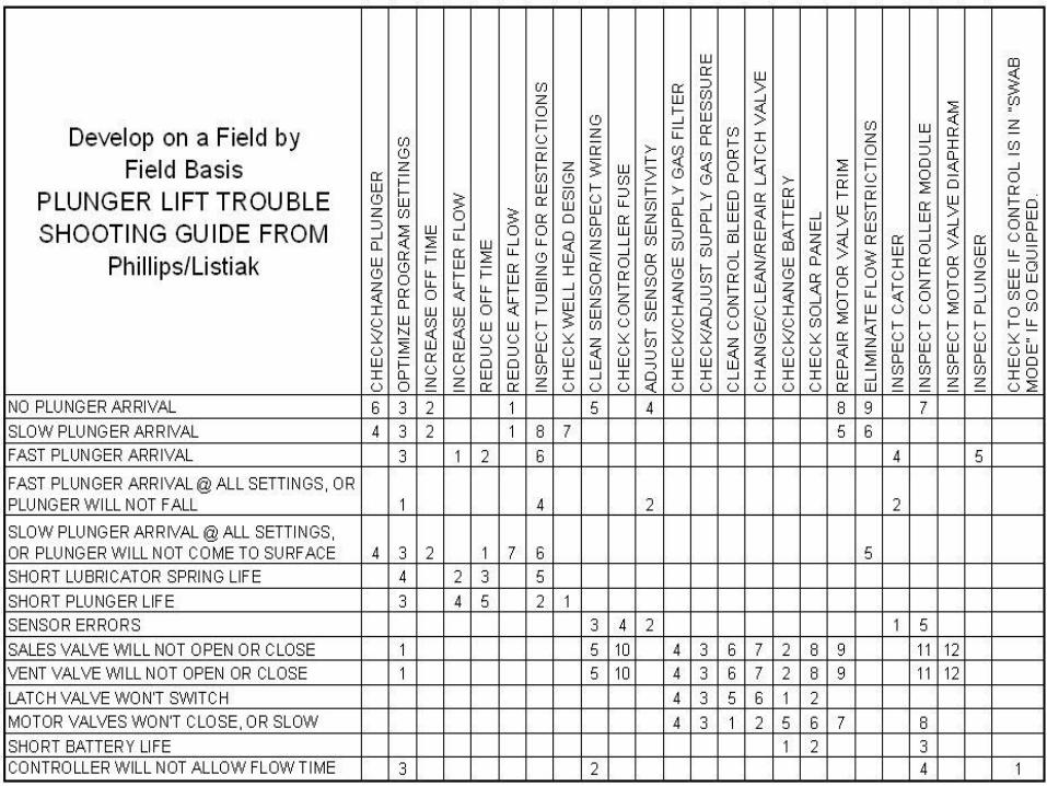
PLUNGER LIFT TROUBLES:
– FAST PLUNGER ARRIVAL
– SHORT LUBRICATOR SPRING LIFE
– SHORT PLUNGER LIFE
Often Caused by Plunger Arriving Dry
– Best Fixed by using Standing Valve @ Bottom to Keep Liquid in Tubing
During Shut-in Time Period
– Use Bumper Springs
– With Standing Valve
– Notch standing valve (May Leak Too Much)
– Use new Spring Loaded Standing valve technology
Standing Valve with Spring Loaded Ball &
Seat will Hold Fluid in Tubing, but Opens
and Dumps Fluid with Too Much Fluid
Load
Where do you set EOT?
• Adjacent to best gas producing zone.
• Run as deep as possible, where plunger will still
cycle
• Move deeper and stop at bottom of perforations
What about a packer?
• Take Out
• Use to Protect Formation when Killing Well
• If a long away from perfs, may present a unloading problem
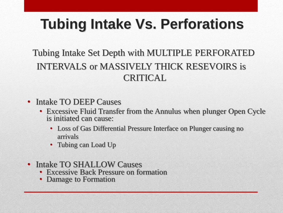
Tubing Intake Vs. Perforations
Tubing Intake Set Depth with MULTIPLE PERFORATED
INTERVALS or MASSIVELY THICK RESEVOIRS is
CRITICAL
• Intake TO DEEP Causes
• Excessive Fluid Transfer from the Annulus when plunger Open Cycle is initiated can cause:
• Loss of Gas Differential Pressure Interface on Plunger causing no
arrivals
• Tubing can Load Up
• Intake TO SHALLOW Causes • Excessive Back Pressure on formation • Damage to Formation
What do you do if well loads up?
• Operate controller in swab mode, with little/no afterflow.
Once arrival velocities become too fast, then add
afterflow to slow down.
When can a tubing extension/flow tube be bad?
• When pressures are low and gas velocity are too high
• Then debris can be sucked into tubing
What do you do if casing is 2 7/8?
• Try plunger lift and control on velocity
• Run tubing stop with bumper, conventional plunger,
check for sand an cleanout if needed
How big should port be in control valve?
• As big as possible, do not want restrictions to flow
• Then debris can be sucked into tubing
Facility Considerations
• Don’t bring on all wells at once
• Use of by-pass type of plungers will upset wells much less
that use of conventional plunger lift
• Low pressure separators and low pressure lines are better
for plunger
• Do Not cause flow restrictions with small lines or bends
or elbows at the wellhead
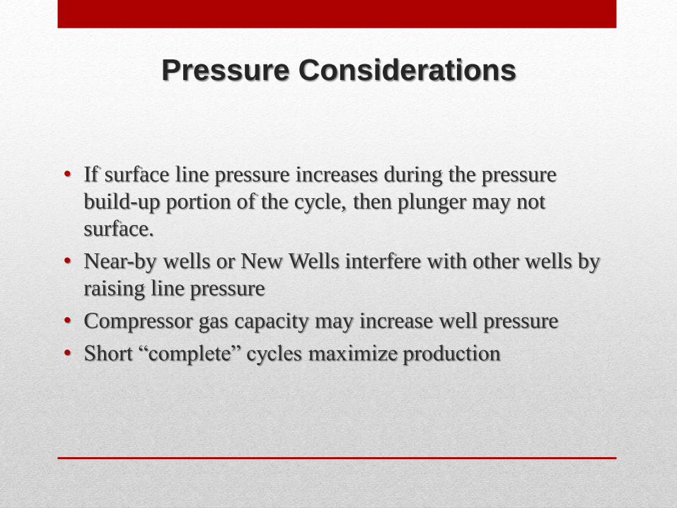
Pressure Considerations
• If surface line pressure increases during the pressure
build-up portion of the cycle, then plunger may not
surface.
• Near-by wells or New Wells interfere with other wells by
raising line pressure
• Compressor gas capacity may increase well pressure
• Short “complete” cycles maximize production
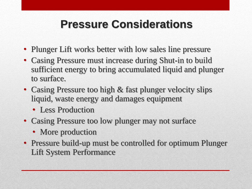
Pressure Considerations
• Plunger Lift works better with low sales line pressure
• Casing Pressure must increase during Shut-in to build sufficient energy to bring accumulated liquid and plunger to surface.
• Casing Pressure too high & fast plunger velocity slips liquid, waste energy and damages equipment
• Less Production
• Casing Pressure too low plunger may not surface
• More production
• Pressure build-up must be controlled for optimum Plunger Lift System Performance
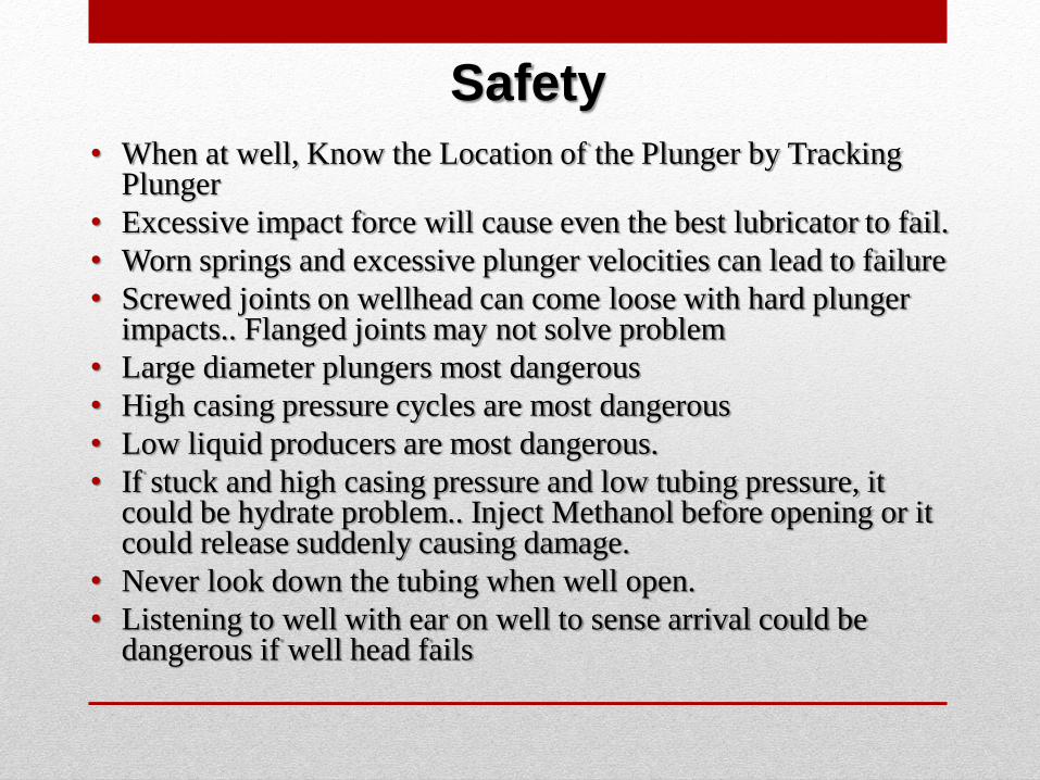
Safety
• When at well, Know the Location of the Plunger by Tracking Plunger
• Excessive impact force will cause even the best lubricator to fail.
• Worn springs and excessive plunger velocities can lead to failure
• Screwed joints on wellhead can come loose with hard plunger impacts.. Flanged joints may not solve problem
• Large diameter plungers most dangerous
• High casing pressure cycles are most dangerous
• Low liquid producers are most dangerous.
• If stuck and high casing pressure and low tubing pressure, it could be hydrate problem.. Inject Methanol before opening or it could release suddenly causing damage.
• Never look down the tubing when well open.
• Listening to well with ear on well to sense arrival could be dangerous if well head fails
PLUNGER LIFT TROUBLES:
1. Some Suppliers incentive is to sell equipment and do
installs.
2. Service and support often is not available.
3. Some operators are uncomfortable with plunger lift
4. Some operators do not maintain up-to-date
service/inspection/maintenance records.
5. Training often to General – More Job specific training
needed.
6. Controllers too complicated - Plunger performance is
dependent on the operators interaction with all of the
elements: the plunger, surface equipment, down hole
assembly, produced fluids, wellbore, and the reservoir.
PLUNGER LIFT Problems: Hardware
1. Short Lubricator Spring Life
2. Short Plunger Life
3. Solid Plungers are often inefficient
4. Fast are very under-utilized
5. One of the biggest issues is incorrect measurement;
Often EFM and RTU changes result in erroneous gas
measurement
6. No standing valve or Leaky standing valve have been
reported to account for 80% of all plunger lift failures
1. Rely on information given to me
2. Lack of data.
3. Interpretation of the data.
4. Plunger fall time
if plunger is making to bottom
rate it is falling in relation to gas flow.
5. Plunger speed
6. Dry runs
7. Plunger not bringing fluid/not traveling
8. Shut-in time to bring fluids to surface
Problems Faced in Optimizing/analysis of plunger lift installations OR identifying a liquid loaded well
1. How to Optimize Well
2. Not knowing where the plunger is
3. What is the plunger doing during a cycle
4. Not knowing what is going on down hole..
5. Getting the plunger box programmed
6. Getting the plunger to bottom by shut off time
7. Not have the well shut in to long or short
8. Flowing the well to short or to long.
9. Getting the best cycles on a well.
Plunger Lift Problems - Optimization
1. Need to know if plunger makes it to bottom with sand
and salt in tubing.
2. Hydrates in well bore.
3. Cold Temperatures.
4. Large water rates.
5. Liquid loading and sand.
6. Liquids on wells and loading up.
7. Liquid loading, freezing, low pressure.
Plunger Lift Problems - Well
1. Operator time
2. Do not maintain up-to-date
service/inspection/maintenance records.
3. Some operators are uncomfortable with plunger lift
4. Pumpers set controller for their convenience.
5. Use general settings for all plunger lift gas wells with no
concern for optimization.
6. Getting pumpers and foreman to buy into
recommendation. Hard to convince them.
7. Employees not knowing how plunger operates or how to
adjust accordingly.
8. Training often to General – More Job specific training
needed.
Plunger Lift Problems - People
Conclusions for Analyzing & Troubleshooting
Plunger Lift Operations
1. Plunger fall velocity can be accurately measured with an
acoustic instrument,
2. Minimum shut-in time for the plunger lift installation can be
determined.
3. Plunger fall measurements will ensure that the plunger will
reach the fluid at the bottom of the tubing by the end of the
shut-in period.
4. Holes in the tubing are identified by observing changes in the
plunger fall velocity and in the tubing pressure.
5. Use the correct plunger for the well ~ High pressure from
long shut-ins can reduce gas rate.