Embed Size (px)
Citation preview
RUI/Gateway & EtherNet/IPTM Configuration & Ladder Logic Example Using an Allen-Bradley CompactLogix PLC
© 2013 Watlow Electric Mfg Co Telephone: 507-494-5656 1 1/28
EtherNet/IP Fundamentals
EtherNet/IP is built on the Common Industrial Protocol (CIP) at a foundational level. When communicating using CIP there are two ways to communicate to/from the Master and Slave devices, i.e., Implicitly (real-time I/O messaging) and Explicitly (information/configuration messaging). For your reference, the Watlow device is always the Slave where the PLC is the Master on the network. This document will look closely at both methods of communication.
Explicit Communications - Defined
This type of messaging is executed on demand and can vary in size. Every message must be individually configured to execute a specific Message Type, e.g., CIP Generic and a specific Service Type, e.g., Get Attribute Single. Each device will interpret the message, act upon the task and then generate a response. This message type encapsulates information about the protocol itself as well as the instructions that need to be carried out in a TCP/IP packet. When a message is sent using TCP/IP it requires a response from the device. As stated above, this type of message is generally reserved for diagnostics and configuration.
Implicit Communications - Defined
Because implicit messaging is real-time I/O messaging, it places different demands on the system. Due to the time critical nature of this form of communications the protocol must be able to support multi-casting while also ensuring that the time to execute the task is as fast as possible. To do this effectively, EtherNet/IP incorporates a protocol called User Datagram Protocol/Internet Protocol (UDP). Basically, this protocol contains the data alone without requiring a response from the Slave device. All data that is passed implicitly is defined in the configuration or start up process. Because this method of communications contains the predefined data alone, it is considered to be low overhead and is therefore able to deliver the time-critical requirements for control.
By using both forms of communication EtherNet/IP can prioritize time-critical I/O communications over non-critical messages while allowing for both to occur simultaneously. Watlow EtherNet/IP equipped devices supports both forms (Explicit/Implicit) of communications.
1.0 Getting Started
Prior to configuring the EZ-ZONE Remote User Interface (RUI) / Gateway (GTW) it is important to think through the needs of the application while also understanding some basic facts that pertain to the RUI/GTW. Note: This document will not cover basic configuration of the RUI/GTW for this is covered in
the RUI/GTW User’s Guide which can be found on the Watlow website; link provided below. http://www.watlow.com/literature/manuals.cfm.
RUI/Gateway & EtherNet/IPTM Configuration & Ladder Logic Example Using an Allen-Bradley CompactLogix PLC
© 2013 Watlow Electric Mfg Co Telephone: 507-494-5656 2 1/28
1.1 Noteworthy RUI/GTW Facts
1.1.1 The RUI/GTW allows for communications to take place between dissimilar networks, e.g., Watlow’s Standard Bus to EtherNet/IP.
1.1.2 There can be up to eight RUIs on an EZ-ZONE network where four of which, can have communications cards installed, i.e., EtherNet/IP, DeviceNet, etc….
1.1.3 Fastest refresh (requested packet interval) should not exceed 250ms. 1.1.4 In this documentation, the RUI/GTW input assembly is referred to as the
Originator to Target (O to T, instance 1) assembly where the RUI/GTW output assembly is referred to as the Target to Originator (T to O, instance 2). The Originator is the Master (usually a PLC) and the Target is the Slave (EZ-ZONE RUI/GTW) ).
1.1.5 All EZ-ZONE assembly members (inputs and outputs) are 32-bits.
1.2 Understanding the Application Requirements
1.2.1 Will there be a need to infrequently read or write parameters between the Master and Slave? Explicit communications can be executed with minimal effort to accomplish this task. Setup and configuration can be found below (see: Explicit Communications Configuration Step-by-Step).
1.2.2 If using implicit communications determine what data (EZ-ZONE parameters) will be transferred implicitly (inputs and outputs) between the Master and Slave ensuring that the maximum number of members is not exceeded for any given module (20). Refer to the product specific EZ-ZONE User’s Guide to find parameters of choice as well as limitations in size. Click on the link below to retrieve the document of choice from the Watlow website. http://www.watlow.com/literature/manuals.cfm
1.2.3 Will the default EZ-ZONE module assemblies meet the application requirements or will the module assembly need to be modified? To answer this question, refer to the User’s Guide in the previous step to evaluate the default assemblies for each EZ-ZONE device.
1.2.4 How fast does the assembly information (I/O) need to be refreshed? When communicating implicitly, the Master (PLC) controls the cyclic timing (I/O updates) via a setting referred to as the Requested Packet Interval (RPI). Note: Suggested RPI setting should be set between 250 and 500ms
2.0 Explicit Communications
2.1 Configuration
It should be noted here that if it is determined that the default Implicit Assemblies need to be changed (step 1.2.3 above), this is the communications method to use to accomplish that
RUI/Gateway & EtherNet/IPTM Configuration & Ladder Logic Example Using an Allen-Bradley CompactLogix PLC
© 2013 Watlow Electric Mfg Co Telephone: 507-494-5656 3 1/28
task. To establish explicit communications between Master and Slave devices, configuration steps need to be executed within the PLC as well as within the RUI/GTW. After the configuration requirements have been met, programming examples will follow.
RUI/GTW Configuration - Required Steps Using EZ-ZONE Configurator Software a. Identify the RUI/GTW on the Ethernet network via an IP address b. Enable EtherNet/IP c. Enable the appropriate gateway instance (EZ-ZONE device address) d. Define the CIP Instance Offset (if more than one EZ-ZONE device is on the
Standard Bus network). See note in step 2.4.4 for more information. e. Define the I/O Implicit Assembly size
PLC Configuration - Required Step Using RSLogix5000 Software a. Add a Generic Ethernet module to the PLC I/O structure b. Configure the module properties, e.g., IP address, Assembly size, etc…
2.2 RUI/GTW Configuration, Step-by-Step
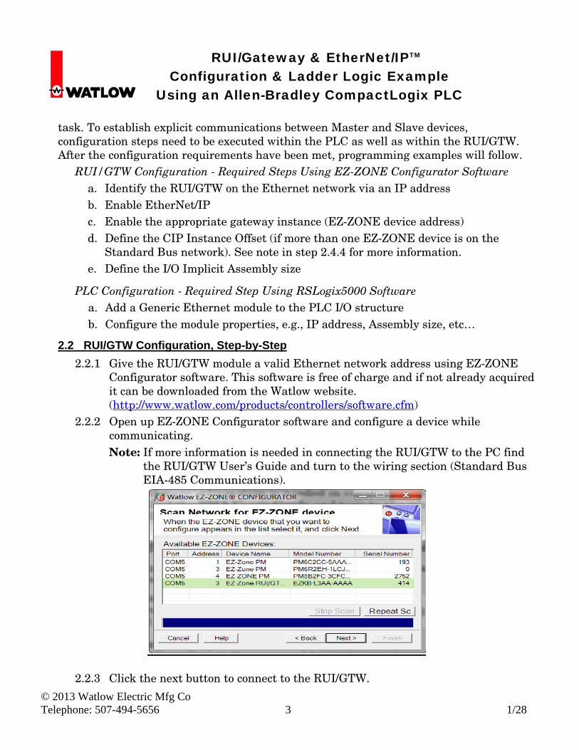
2.2.1 Give the RUI/GTW module a valid Ethernet network address using EZ-ZONE Configurator software. This software is free of charge and if not already acquired it can be downloaded from the Watlow website. (http://www.watlow.com/products/controllers/software.cfm)
2.2.2 Open up EZ-ZONE Configurator software and configure a device while communicating. Note: If more information is needed in connecting the RUI/GTW to the PC find
the RUI/GTW User’s Guide and turn to the wiring section (Standard Bus EIA-485 Communications).
2.2.3 Click the next button to connect to the RUI/GTW.
RUI/Gateway & EtherNet/IPTM Configuration & Ladder Logic Example Using an Allen-Bradley CompactLogix PLC
© 2013 Watlow Electric Mfg Co Telephone: 507-494-5656 4 1/28
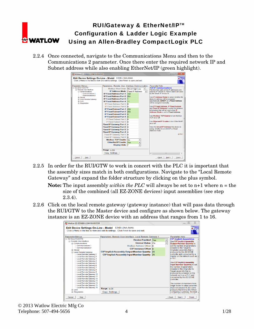
2.2.4 Once connected, navigate to the Communications Menu and then to the
Communications 2 parameter. Once there enter the required network IP and Subnet address while also enabling EtherNet/IP (green highlight).
2.2.5 In order for the RUI/GTW to work in concert with the PLC it is important that
the assembly sizes match in both configurations. Navigate to the “Local Remote Gateway” and expand the folder structure by clicking on the plus symbol. Note: The input assembly within the PLC will always be set to n+1 where n = the
size of the combined (all EZ-ZONE devices) input assemblies (see step 2.3.4).
2.2.6 Click on the local remote gateway (gateway instance) that will pass data through the RUI/GTW to the Master device and configure as shown below. The gateway instance is an EZ-ZONE device with an address that ranges from 1 to 16.
RUI/Gateway & EtherNet/IPTM Configuration & Ladder Logic Example Using an Allen-Bradley CompactLogix PLC
© 2013 Watlow Electric Mfg Co Telephone: 507-494-5656 5 1/28
2.2.7 If explicit messaging will be used alone, the minimum assembly size requirement
(from the PLC perspective) is 1 input and 1 output. Again, the assembly size must be the same in the PLC and the RUI/GTW. In the previous step, the graphic shows the assemblies set to twenty. This was done now for implicit communica- tion examples that will follow later in this document.
2.3 PLC Configuration, Step-by-Step
2.3.1 Open RSLogix5000 software and add an additional I/O module. Follow the steps below to accomplish this task.
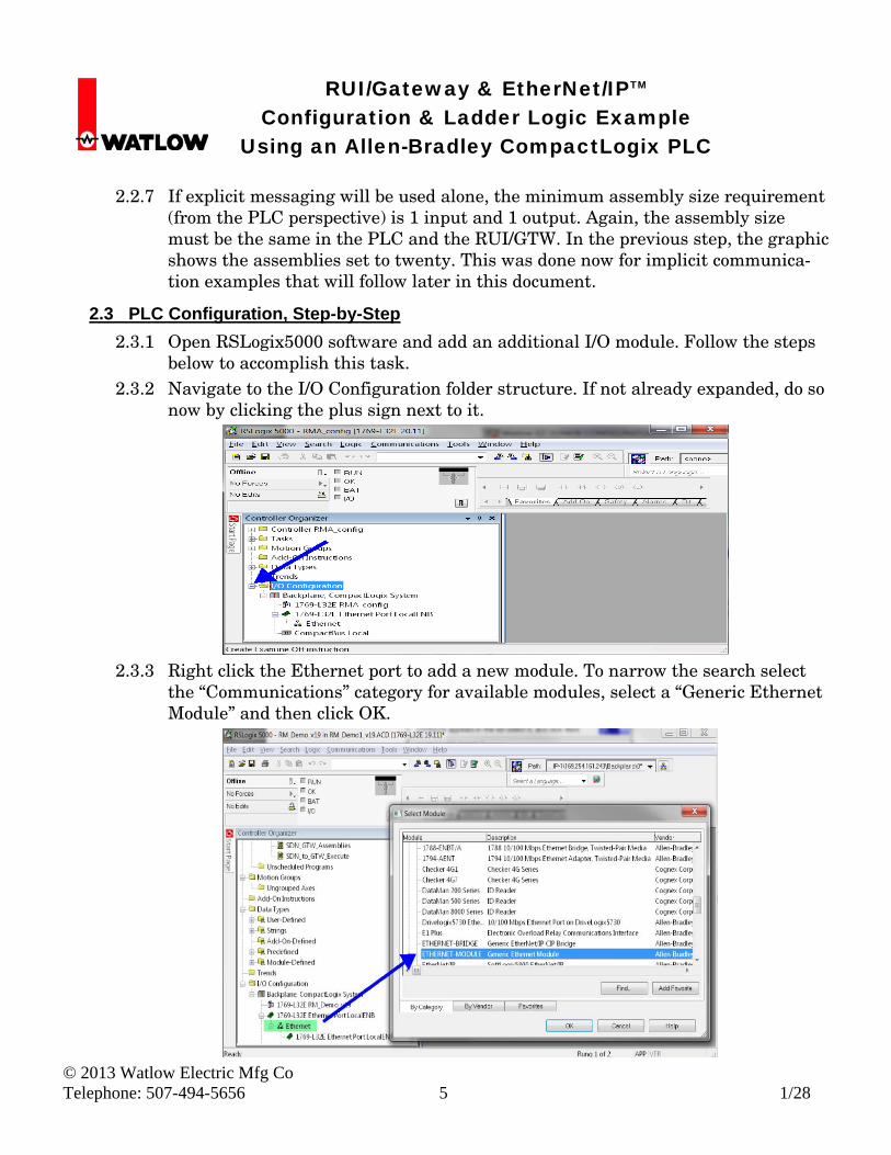
2.3.2 Navigate to the I/O Configuration folder structure. If not already expanded, do so now by clicking the plus sign next to it.
2.3.3 Right click the Ethernet port to add a new module. To narrow the search select
the “Communications” category for available modules, select a “Generic Ethernet Module” and then click OK.
RUI/Gateway & EtherNet/IPTM Configuration & Ladder Logic Example Using an Allen-Bradley CompactLogix PLC
© 2013 Watlow Electric Mfg Co Telephone: 507-494-5656 6 1/28
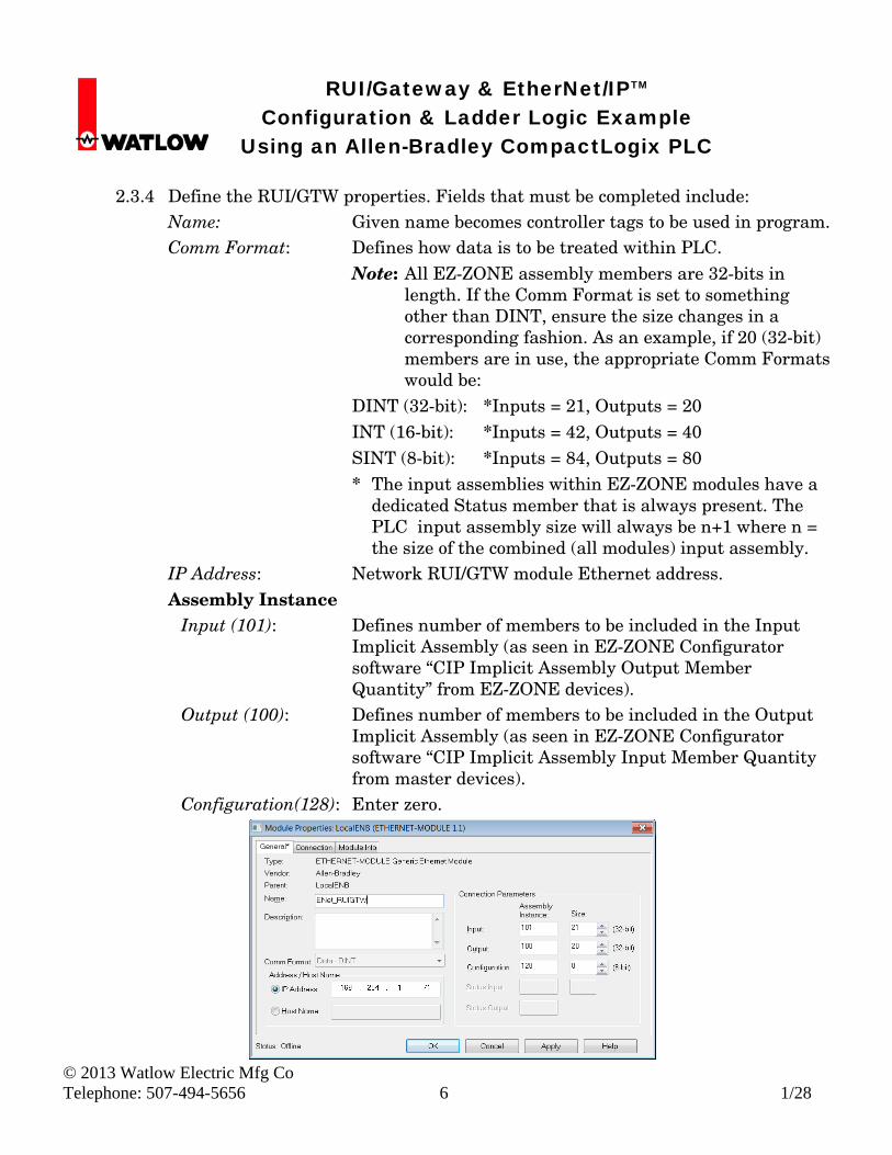
2.3.4 Define the RUI/GTW properties. Fields that must be completed include:
Name: Given name becomes controller tags to be used in program. Comm Format: Defines how data is to be treated within PLC.
Note: All EZ-ZONE assembly members are 32-bits in length. If the Comm Format is set to something other than DINT, ensure the size changes in a corresponding fashion. As an example, if 20 (32-bit) members are in use, the appropriate Comm Formats would be:
DINT (32-bit): *Inputs = 21, Outputs = 20 INT (16-bit): *Inputs = 42, Outputs = 40 SINT (8-bit): *Inputs = 84, Outputs = 80 * The input assemblies within EZ-ZONE modules have a
dedicated Status member that is always present. The PLC input assembly size will always be n+1 where n = the size of the combined (all modules) input assembly.
IP Address: Network RUI/GTW module Ethernet address. Assembly Instance
Input (101): Defines number of members to be included in the Input Implicit Assembly (as seen in EZ-ZONE Configurator software “CIP Implicit Assembly Output Member Quantity” from EZ-ZONE devices).
Output (100): Defines number of members to be included in the Output Implicit Assembly (as seen in EZ-ZONE Configurator software “CIP Implicit Assembly Input Member Quantity from master devices).
Configuration(128): Enter zero.
RUI/Gateway & EtherNet/IPTM Configuration & Ladder Logic Example Using an Allen-Bradley CompactLogix PLC
© 2013 Watlow Electric Mfg Co Telephone: 507-494-5656 7 1/28
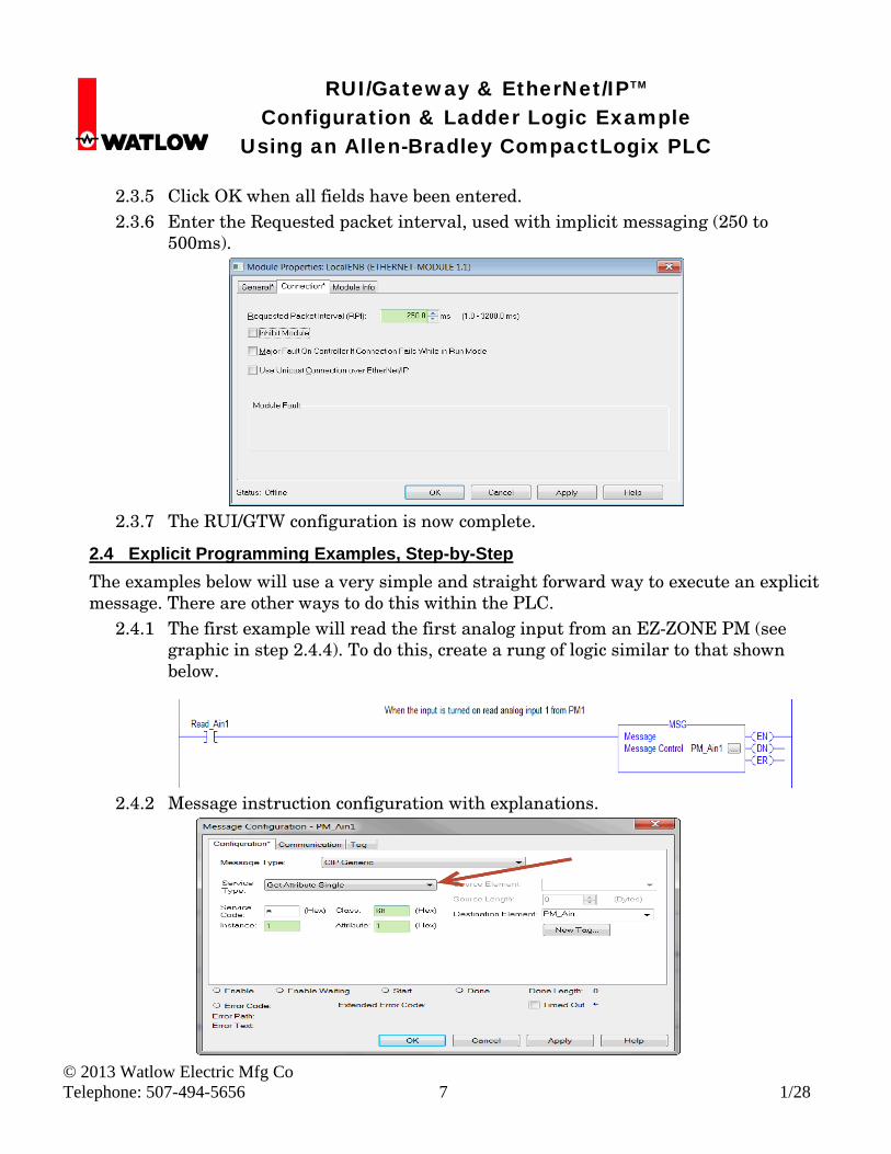
2.3.5 Click OK when all fields have been entered. 2.3.6 Enter the Requested packet interval, used with implicit messaging (250 to
500ms).
2.3.7 The RUI/GTW configuration is now complete.
2.4 Explicit Programming Examples, Step-by-Step
The examples below will use a very simple and straight forward way to execute an explicit message. There are other ways to do this within the PLC.
2.4.1 The first example will read the first analog input from an EZ-ZONE PM (see graphic in step 2.4.4). To do this, create a rung of logic similar to that shown below.
2.4.2 Message instruction configuration with explanations.
RUI/Gateway & EtherNet/IPTM Configuration & Ladder Logic Example Using an Allen-Bradley CompactLogix PLC
© 2013 Watlow Electric Mfg Co Telephone: 507-494-5656 8 1/28
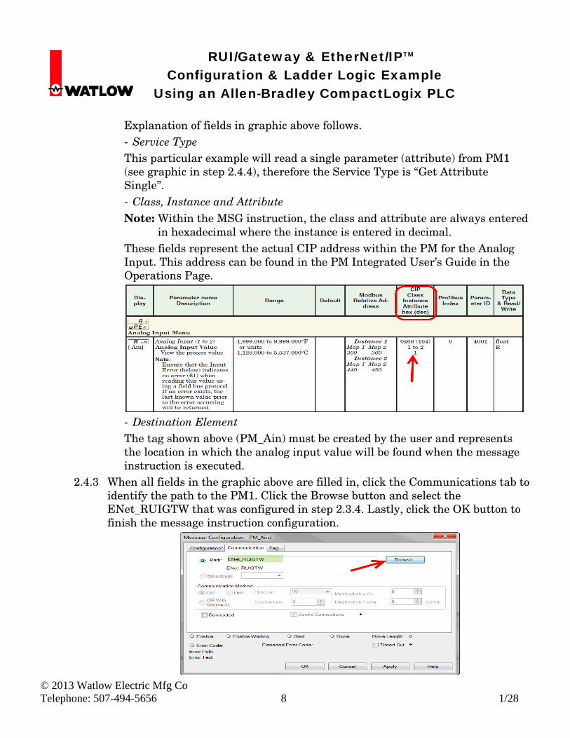
Explanation of fields in graphic above follows. - Service Type This particular example will read a single parameter (attribute) from PM1 (see graphic in step 2.4.4), therefore the Service Type is “Get Attribute Single”. - Class, Instance and Attribute Note: Within the MSG instruction, the class and attribute are always entered
in hexadecimal where the instance is entered in decimal. These fields represent the actual CIP address within the PM for the Analog Input. This address can be found in the PM Integrated User’s Guide in the Operations Page.
- Destination Element The tag shown above (PM_Ain) must be created by the user and represents the location in which the analog input value will be found when the message instruction is executed.
2.4.3 When all fields in the graphic above are filled in, click the Communications tab to identify the path to the PM1. Click the Browse button and select the ENet_RUIGTW that was configured in step 2.3.4. Lastly, click the OK button to finish the message instruction configuration.
RUI/Gateway & EtherNet/IPTM Configuration & Ladder Logic Example Using an Allen-Bradley CompactLogix PLC
© 2013 Watlow Electric Mfg Co Telephone: 507-494-5656 9 1/28
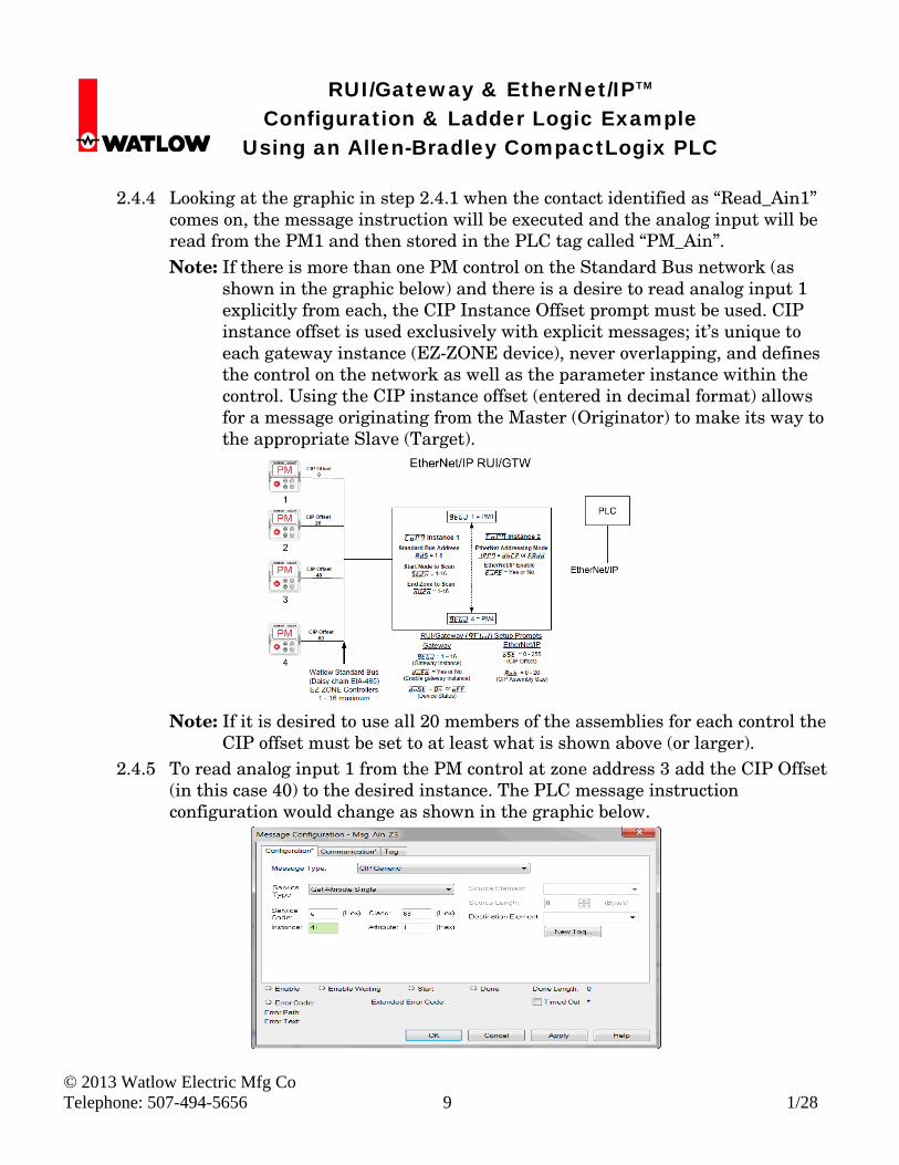
2.4.4 Looking at the graphic in step 2.4.1 when the contact identified as “Read_Ain1”
comes on, the message instruction will be executed and the analog input will be read from the PM1 and then stored in the PLC tag called “PM_Ain”. Note: If there is more than one PM control on the Standard Bus network (as
shown in the graphic below) and there is a desire to read analog input 1 explicitly from each, the CIP Instance Offset prompt must be used. CIP instance offset is used exclusively with explicit messages; it’s unique to each gateway instance (EZ-ZONE device), never overlapping, and defines the control on the network as well as the parameter instance within the control. Using the CIP instance offset (entered in decimal format) allows for a message originating from the Master (Originator) to make its way to the appropriate Slave (Target).
Note: If it is desired to use all 20 members of the assemblies for each control the
CIP offset must be set to at least what is shown above (or larger). 2.4.5 To read analog input 1 from the PM control at zone address 3 add the CIP Offset
(in this case 40) to the desired instance. The PLC message instruction configuration would change as shown in the graphic below.
RUI/Gateway & EtherNet/IPTM Configuration & Ladder Logic Example Using an Allen-Bradley CompactLogix PLC
© 2013 Watlow Electric Mfg Co Telephone: 507-494-5656 10 1/28
2.5 Modifying Implicit Assemblies Using Explicit Messages, Step-by-Step
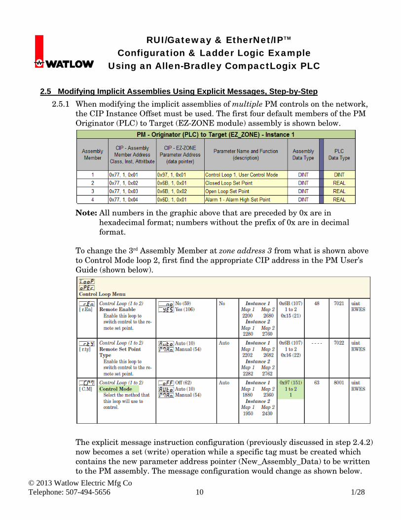
2.5.1 When modifying the implicit assemblies of multiple PM controls on the network, the CIP Instance Offset must be used. The first four default members of the PM Originator (PLC) to Target (EZ-ZONE module) assembly is shown below.
Note: All numbers in the graphic above that are preceded by 0x are in
hexadecimal format; numbers without the prefix of 0x are in decimal format.
To change the 3rd Assembly Member at zone address 3 from what is shown above to Control Mode loop 2, first find the appropriate CIP address in the PM User’s Guide (shown below).
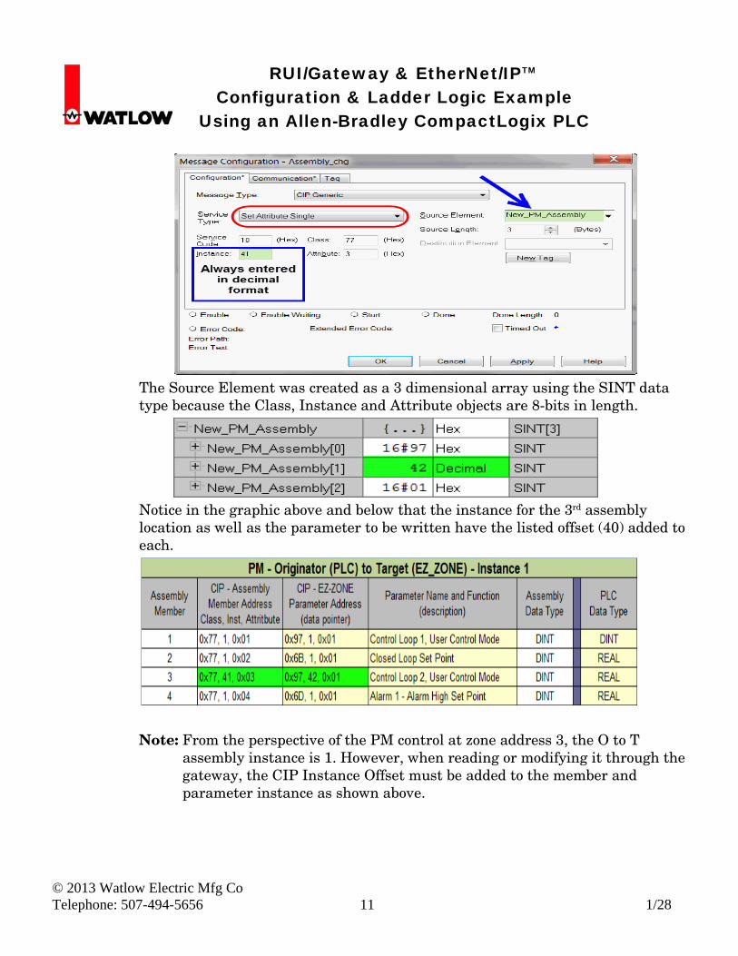
The explicit message instruction configuration (previously discussed in step 2.4.2) now becomes a set (write) operation while a specific tag must be created which contains the new parameter address pointer (New_Assembly_Data) to be written to the PM assembly. The message configuration would change as shown below.
RUI/Gateway & EtherNet/IPTM Configuration & Ladder Logic Example Using an Allen-Bradley CompactLogix PLC
© 2013 Watlow Electric Mfg Co Telephone: 507-494-5656 11 1/28
The Source Element was created as a 3 dimensional array using the SINT data type because the Class, Instance and Attribute objects are 8-bits in length.
Notice in the graphic above and below that the instance for the 3rd assembly location as well as the parameter to be written have the listed offset (40) added to each.
Note: From the perspective of the PM control at zone address 3, the O to T
assembly instance is 1. However, when reading or modifying it through the gateway, the CIP Instance Offset must be added to the member and parameter instance as shown above.
RUI/Gateway & EtherNet/IPTM Configuration & Ladder Logic Example Using an Allen-Bradley CompactLogix PLC
© 2013 Watlow Electric Mfg Co Telephone: 507-494-5656 12 1/28
3.0 Implicit Communications
3.1 PLC Configuration
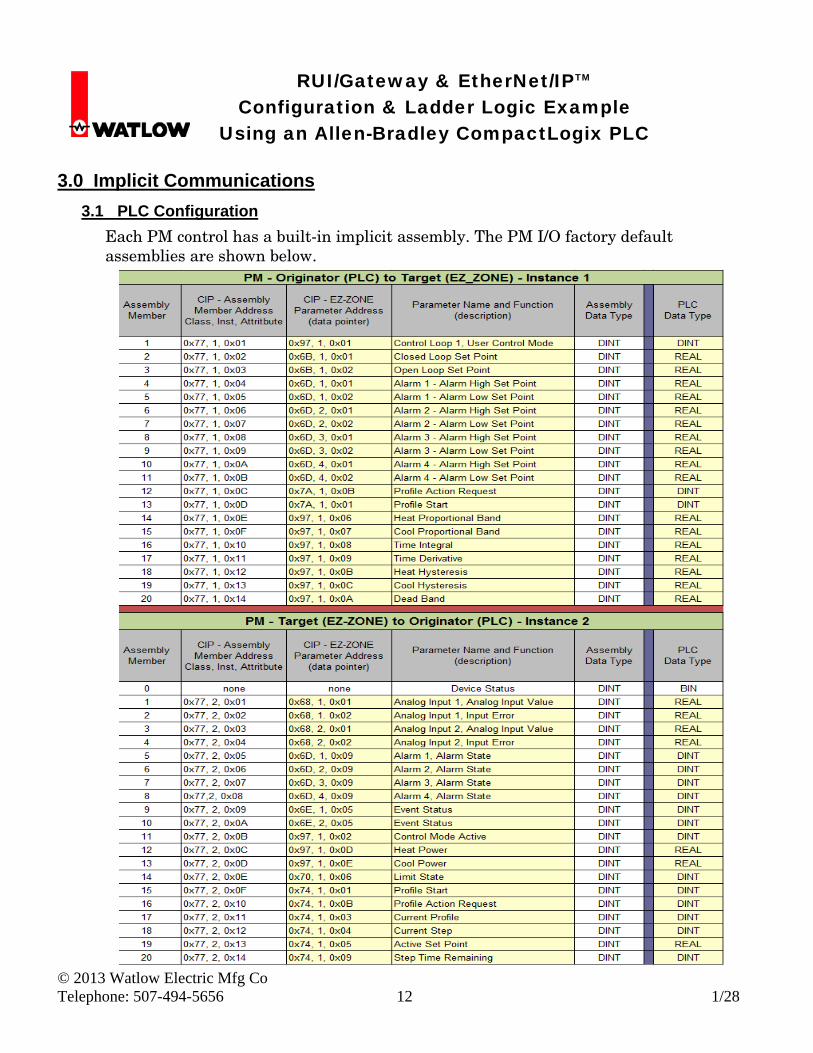
Each PM control has a built-in implicit assembly. The PM I/O factory default assemblies are shown below.
RUI/Gateway & EtherNet/IPTM Configuration & Ladder Logic Example Using an Allen-Bradley CompactLogix PLC
© 2013 Watlow Electric Mfg Co Telephone: 507-494-5656 13 1/28
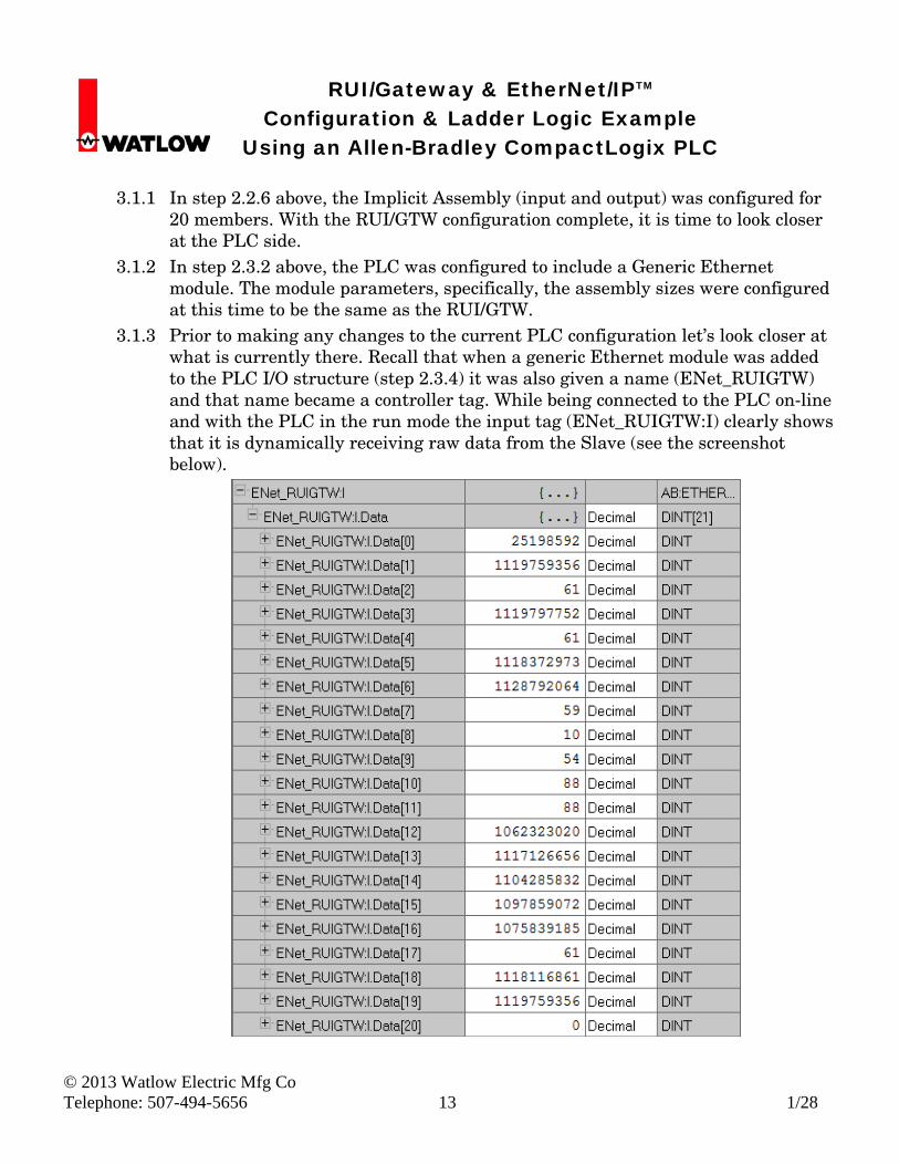
3.1.1 In step 2.2.6 above, the Implicit Assembly (input and output) was configured for
20 members. With the RUI/GTW configuration complete, it is time to look closer at the PLC side.
3.1.2 In step 2.3.2 above, the PLC was configured to include a Generic Ethernet module. The module parameters, specifically, the assembly sizes were configured at this time to be the same as the RUI/GTW.
3.1.3 Prior to making any changes to the current PLC configuration let’s look closer at what is currently there. Recall that when a generic Ethernet module was added to the PLC I/O structure (step 2.3.4) it was also given a name (ENet_RUIGTW) and that name became a controller tag. While being connected to the PLC on-line and with the PLC in the run mode the input tag (ENet_RUIGTW:I) clearly shows that it is dynamically receiving raw data from the Slave (see the screenshot below).
RUI/Gateway & EtherNet/IPTM Configuration & Ladder Logic Example Using an Allen-Bradley CompactLogix PLC
© 2013 Watlow Electric Mfg Co Telephone: 507-494-5656 14 1/28
3.2 PLC Programming
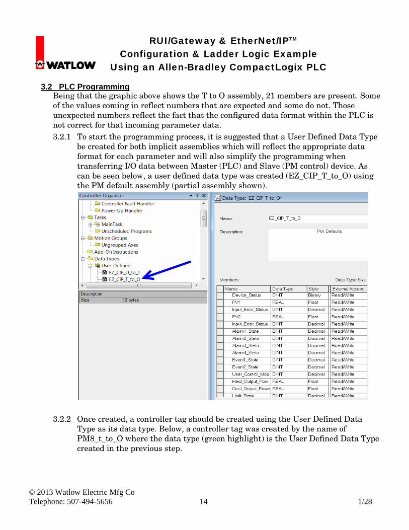
Being that the graphic above shows the T to O assembly, 21 members are present. Some of the values coming in reflect numbers that are expected and some do not. Those unexpected numbers reflect the fact that the configured data format within the PLC is not correct for that incoming parameter data. 3.2.1 To start the programming process, it is suggested that a User Defined Data Type
be created for both implicit assemblies which will reflect the appropriate data format for each parameter and will also simplify the programming when transferring I/O data between Master (PLC) and Slave (PM control) device. As can be seen below, a user defined data type was created (EZ_CIP_T_to_O) using the PM default assembly (partial assembly shown).
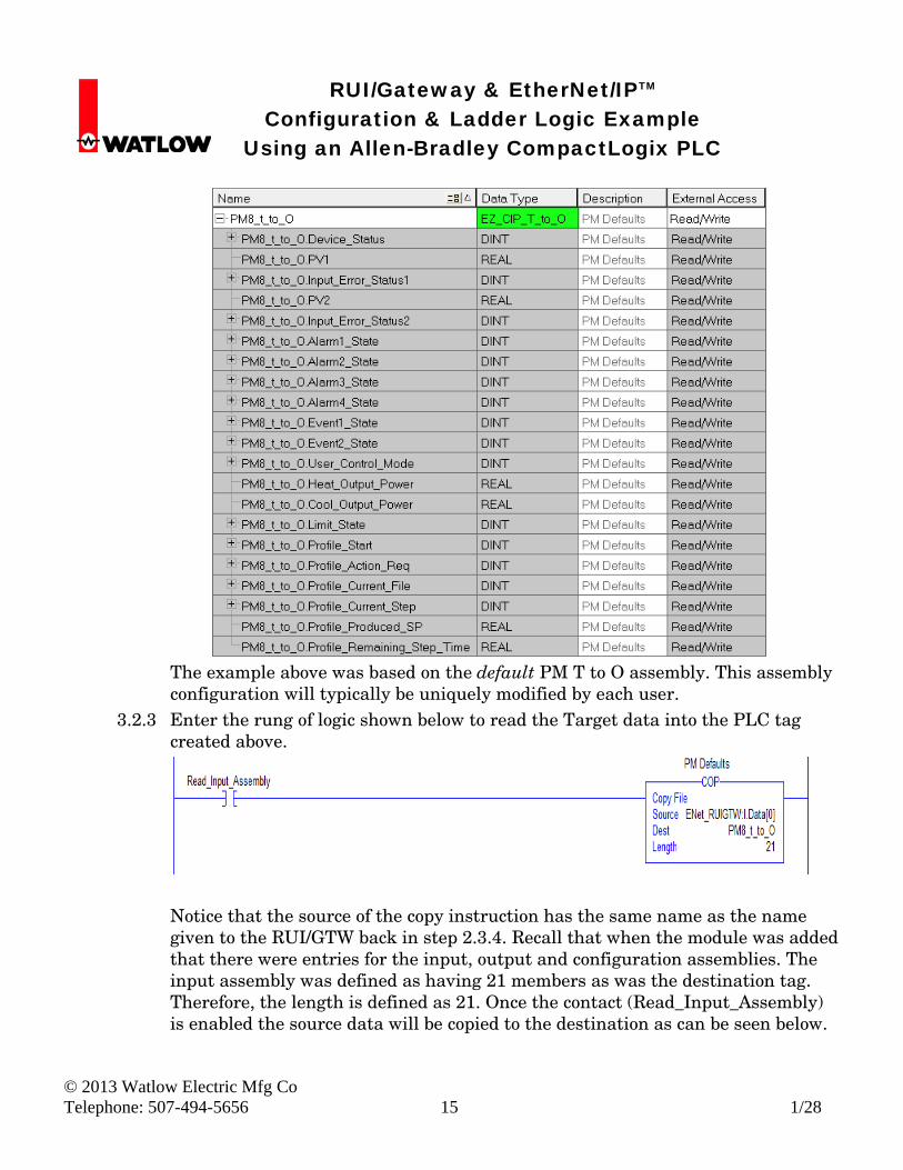
3.2.2 Once created, a controller tag should be created using the User Defined Data Type as its data type. Below, a controller tag was created by the name of PM8_t_to_O where the data type (green highlight) is the User Defined Data Type created in the previous step.
RUI/Gateway & EtherNet/IPTM Configuration & Ladder Logic Example Using an Allen-Bradley CompactLogix PLC
© 2013 Watlow Electric Mfg Co Telephone: 507-494-5656 15 1/28
The example above was based on the default PM T to O assembly. This assembly configuration will typically be uniquely modified by each user.
3.2.3 Enter the rung of logic shown below to read the Target data into the PLC tag created above.
Notice that the source of the copy instruction has the same name as the name given to the RUI/GTW back in step 2.3.4. Recall that when the module was added that there were entries for the input, output and configuration assemblies. The input assembly was defined as having 21 members as was the destination tag. Therefore, the length is defined as 21. Once the contact (Read_Input_Assembly) is enabled the source data will be copied to the destination as can be seen below.
RUI/Gateway & EtherNet/IPTM Configuration & Ladder Logic Example Using an Allen-Bradley CompactLogix PLC
© 2013 Watlow Electric Mfg Co Telephone: 507-494-5656 16 1/28
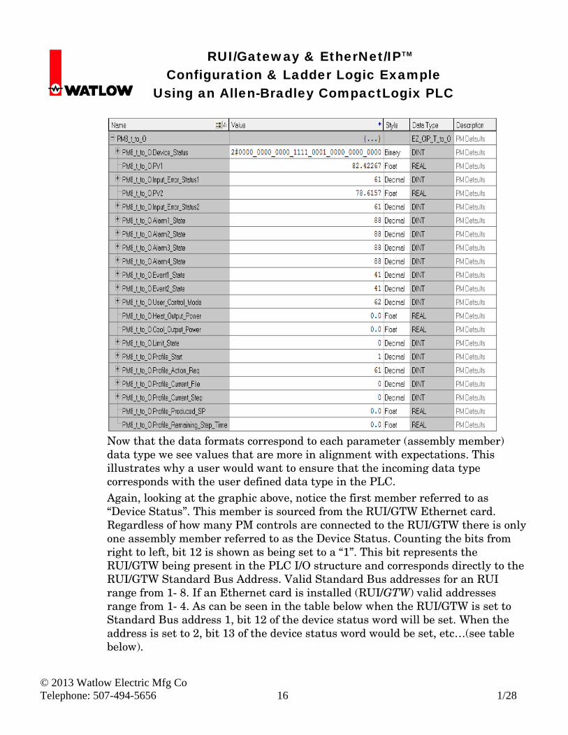
Now that the data formats correspond to each parameter (assembly member) data type we see values that are more in alignment with expectations. This illustrates why a user would want to ensure that the incoming data type corresponds with the user defined data type in the PLC.
Again, looking at the graphic above, notice the first member referred to as “Device Status”. This member is sourced from the RUI/GTW Ethernet card. Regardless of how many PM controls are connected to the RUI/GTW there is only one assembly member referred to as the Device Status. Counting the bits from right to left, bit 12 is shown as being set to a “1”. This bit represents the RUI/GTW being present in the PLC I/O structure and corresponds directly to the RUI/GTW Standard Bus Address. Valid Standard Bus addresses for an RUI range from 1- 8. If an Ethernet card is installed (RUI/GTW) valid addresses range from 1- 4. As can be seen in the table below when the RUI/GTW is set to Standard Bus address 1, bit 12 of the device status word will be set. When the address is set to 2, bit 13 of the device status word would be set, etc…(see table below).
RUI/Gateway & EtherNet/IPTM Configuration & Ladder Logic Example Using an Allen-Bradley CompactLogix PLC
© 2013 Watlow Electric Mfg Co Telephone: 507-494-5656 17 1/28
Device Device Status (bits) Logical RUI/GTW Address (Set by User)
Communication Cards 12-15 1-4 EZ-ZONE® Controllers 16-31 1-16
Bits 16 through 31 of the device status word represent gateway instances (EZ-ZONE controls on Standard Bus). Once the gateway instance is enabled, as long as there is successful communications to the RUI/GTW the corresponding bit/s will be set to a one. Above, bits 16 - 19 (PM Standard Bus addresses 1 - 4) are set to a “1” because each of those four controls were enabled and they are communicating successfully with the RUI/GTW. Note: The other bits (20 through 31) being “0” could represent a module problem
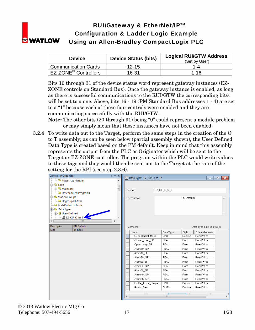
or may simply mean that those instances have not been enabled. 3.2.4 To write data out to the Target, perform the same steps in the creation of the O
to T assembly; as can be seen below (partial assembly shown), the User Defined Data Type is created based on the PM default. Keep in mind that this assembly represents the output from the PLC or Originator which will be sent to the Target or EZ-ZONE controller. The program within the PLC would write values to these tags and they would then be sent out to the Target at the rate of the setting for the RPI (see step 2.3.6).
RUI/Gateway & EtherNet/IPTM Configuration & Ladder Logic Example Using an Allen-Bradley CompactLogix PLC
© 2013 Watlow Electric Mfg Co Telephone: 507-494-5656 18 1/28
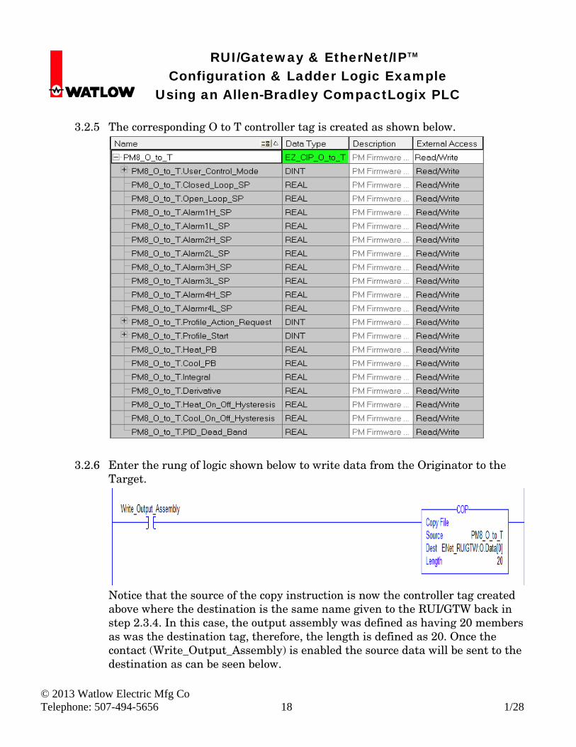
3.2.5 The corresponding O to T controller tag is created as shown below.
3.2.6 Enter the rung of logic shown below to write data from the Originator to the Target.
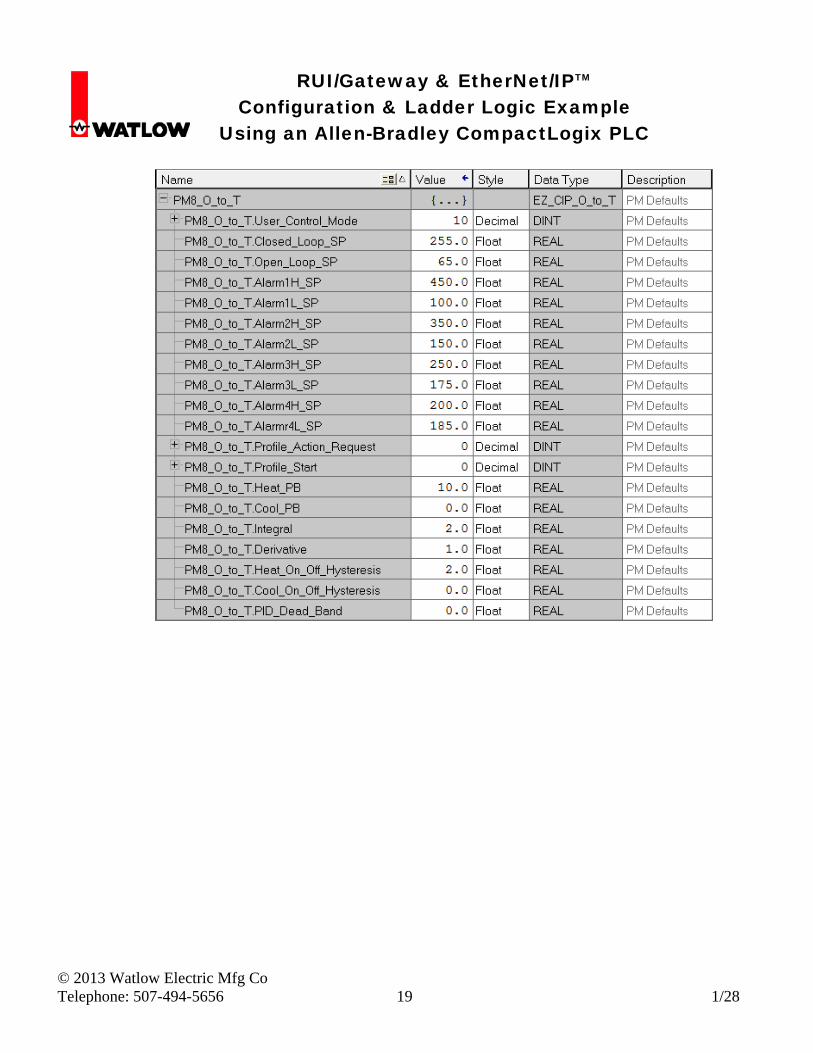
Notice that the source of the copy instruction is now the controller tag created above where the destination is the same name given to the RUI/GTW back in step 2.3.4. In this case, the output assembly was defined as having 20 members as was the destination tag, therefore, the length is defined as 20. Once the contact (Write_Output_Assembly) is enabled the source data will be sent to the destination as can be seen below.
RUI/Gateway & EtherNet/IPTM Configuration & Ladder Logic Example Using an Allen-Bradley CompactLogix PLC
© 2013 Watlow Electric Mfg Co Telephone: 507-494-5656 19 1/28