Embed Size (px)
Citation preview
CT Requirements of Distance RelaysExample MiCOM P43x range
Rudolf Simon, Dr.-Ing.Product Manager
Schneider Electric Energy – Frankfurt / Germany
Agenda
Impact of CT saturation on distance measurementeasu e e
Determination of relays CT requirements
CT sizing based on application data
Schneider Electric 2- AFS/M-F – Rudolf Simon – November 2011
Impact of CT saturation on distance measurement
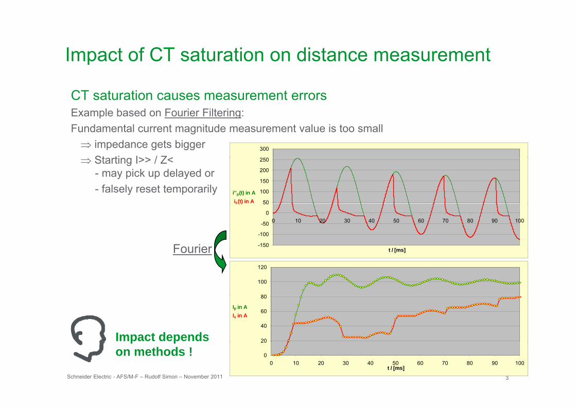
CT saturation causes measurement errorsExample based on Fourier Filtering:Example based on Fourier Filtering:Fundamental current magnitude measurement value is too small⇒ impedance gets bigger
St ti I>> / Z<300
⇒ Starting I>> / Z< - may pick up delayed or - falsely reset temporarily
50
100
150
200
250
i''p(t) in Ais(t) in A
Fourier -150
-100
-50
0
50
0 10 20 30 40 50 60 70 80 90 100
t / [ms]
s( )
Fourier t / [ms]
80
100
120
Impact depends 20
40
60
80
Ip in AIs in A
Schneider Electric 3- AFS/M-F – Rudolf Simon – November 2011
p pon methods ! 0
20
0 10 20 30 40 50 60 70 80 90 100t / [ms]
Impact of CT saturation on distance measurement
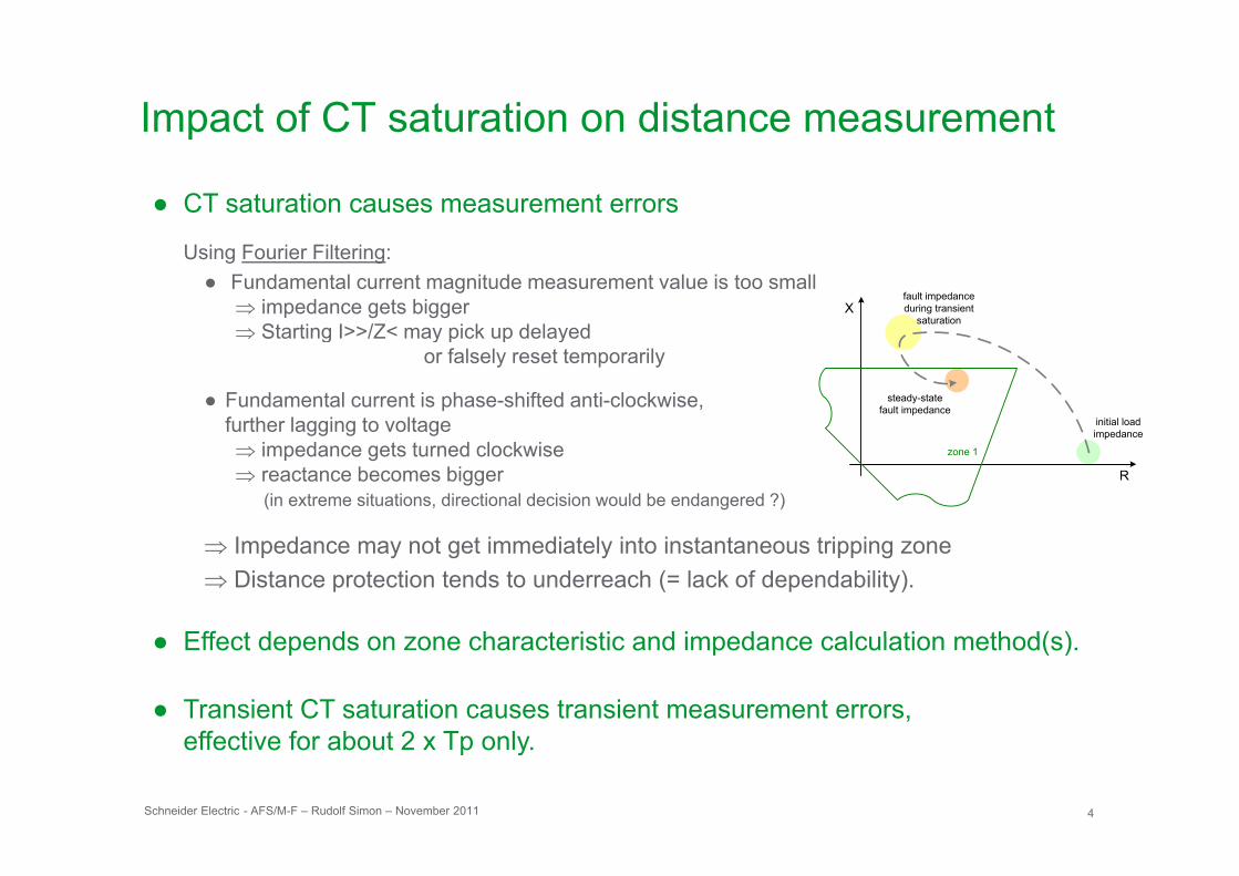
● CT saturation causes measurement errors
Xfault impedanceduring transient
saturation
Using Fourier Filtering:● Fundamental current magnitude measurement value is too small
⇒ impedance gets bigger⇒ Starting I>>/Z< may pick up delayed
initial loadimpedance
steady-state fault impedance
⇒ g y p p yor falsely reset temporarily
● Fundamental current is phase-shifted anti-clockwise, further lagging to voltage
R
p
zone 1⇒ impedance gets turned clockwise ⇒ reactance becomes bigger
(in extreme situations, directional decision would be endangered ?)
I d t t i di t l i t i t t t i i⇒ Impedance may not get immediately into instantaneous tripping zone ⇒ Distance protection tends to underreach (= lack of dependability).
Effect depends on zone characteristic and impedance calculation method(s)● Effect depends on zone characteristic and impedance calculation method(s).
● Transient CT saturation causes transient measurement errors, effective for about 2 x Tp only
Schneider Electric 4- AFS/M-F – Rudolf Simon – November 2011
effective for about 2 x Tp only.
Agenda
Impact of CT saturation on distance measurementeasu e e
Determination of relays CT requirements
CT sizing based on application data
Schneider Electric 5- AFS/M-F – Rudolf Simon – November 2011
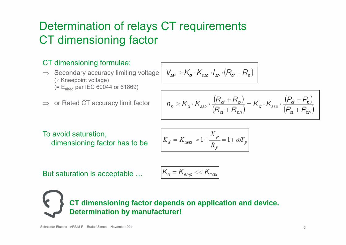
Determination of relays CT requirementsCT dimensioning factorCT dimensioning factor
CT dimensioning formulae:⇒ Secondary accuracy limiting voltage
(≠ Kneepoint voltage)(= Ealreq per IEC 60044 or 61869)
⇒ or Rated CT accuracy limit factor
To avoid saturation, dimensioning factor has to be
But saturation is acceptable …
CT dimensioning factor depends on application and device.
Schneider Electric 6- AFS/M-F – Rudolf Simon – November 2011
g p ppDetermination by manufacturer!
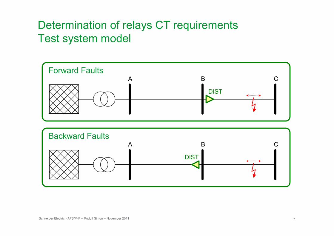
Determination of relays CT requirementsTest system modelTest system model
A B C
DISTDIST
A B CA B C
DIST
Schneider Electric 7- AFS/M-F – Rudolf Simon – November 2011
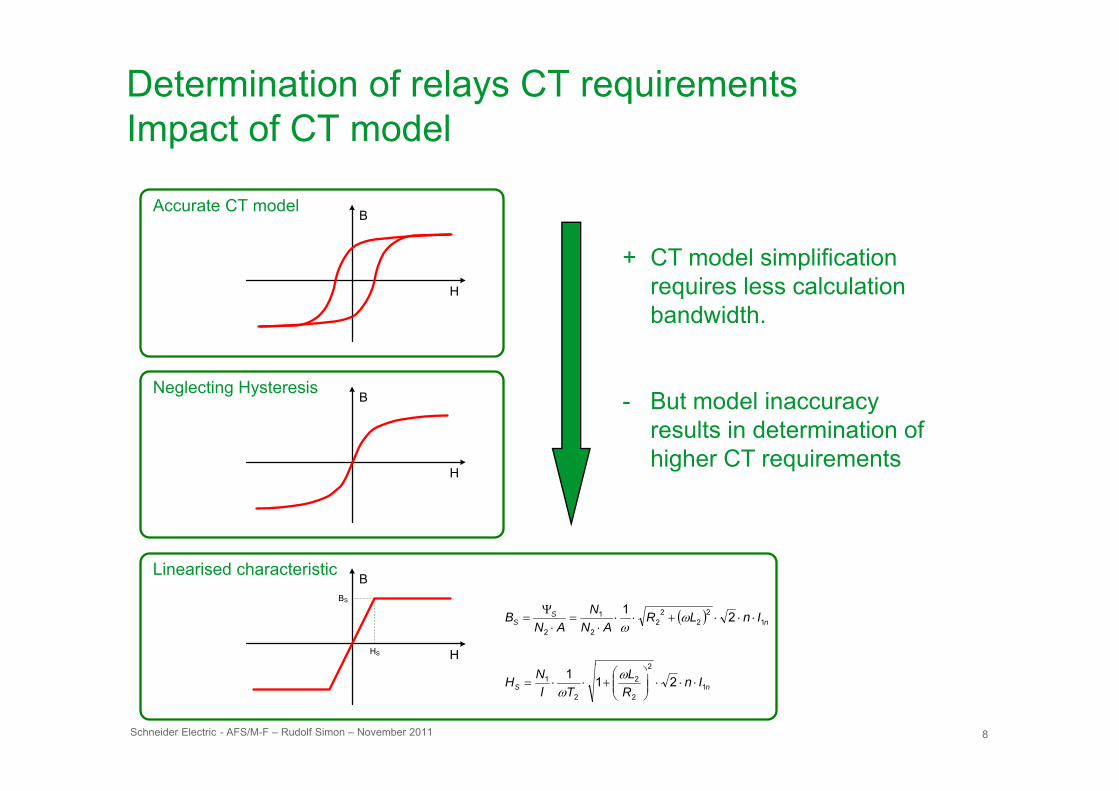
Determination of relays CT requirementsImpact of CT modelImpact of CT model
BAccurate CT model
H
B
+ CT model simplification requires less calculation b d id h
Neglecting Hysteresis B
bandwidth.
B t d l ig g y
H
B - But model inaccuracy results in determination of higher CT requirements
Linearised characteristic B
HS
BS
H
B
( ) nS
S InLRAN
NAN
B
2
12
22
22
1
2
21⋅⋅⋅+⋅⋅
⋅=
⋅Ψ
= ωω
Schneider Electric 8- AFS/M-F – Rudolf Simon – November 2011
nS InRL
TlNH 1
2
2
2
2
1 211⋅⋅⋅⎟⎟
⎠
⎞⎜⎜⎝
⎛+⋅⋅=
ωω
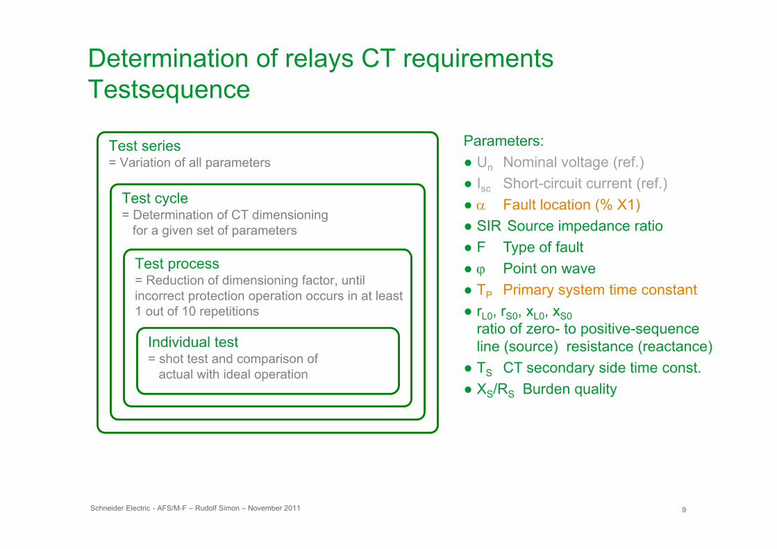
Determination of relays CT requirementsTestsequenceTestsequence
Parameters: Test series● Un Nominal voltage (ref.)● Isc Short-circuit current (ref.)● α Fault location (% X1) Test cycle
D t i ti f CT di i i
Test series= Variation of all parameters
( )● SIR Source impedance ratio● F Type of fault● ϕ Point on waveTest process
= Determination of CT dimensioning for a given set of parameters
ϕ● TP Primary system time constant● rL0, rS0, xL0, xS0
ratio of zero- to positive-sequence I di id l t t
= Reduction of dimensioning factor, until incorrect protection operation occurs in at least 1 out of 10 repetitions
line (source) resistance (reactance) ● TS CT secondary side time const.● XS/RS Burden quality
Individual test= shot test and comparison of actual with ideal operation
Schneider Electric 9- AFS/M-F – Rudolf Simon – November 2011
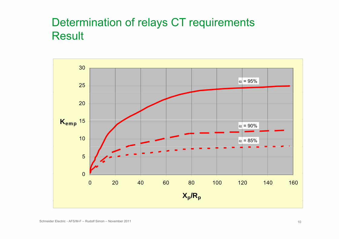
Determination of relays CT requirementsResultResult
25
30
α = 95%
15
20
K
10
15Kemp
α = 85%
α = 90%
0
5
00 20 40 60 80 100 120 140 160
Xp/Rp
Schneider Electric 10- AFS/M-F – Rudolf Simon – November 2011
Agenda
Impact of CT saturation on distance measurementeasu e e
Determination of relays CT requirements
CT sizing based on application data
Schneider Electric 11- AFS/M-F – Rudolf Simon – November 2011
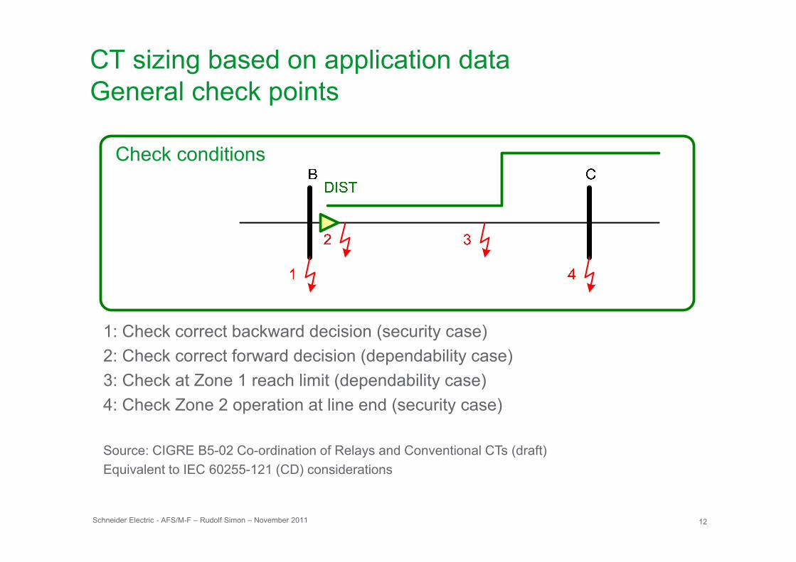
CT sizing based on application dataGeneral check pointsGeneral check points
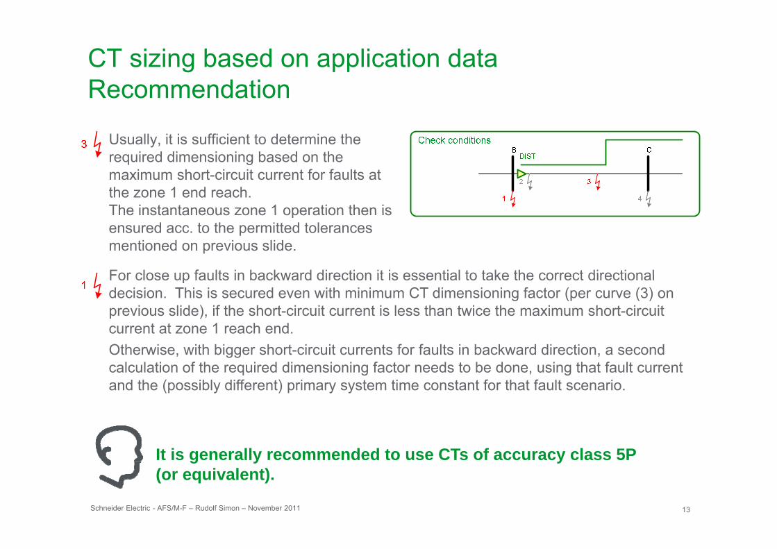
1: Check correct backward decision (security case)2: Check correct forward decision (dependability case)3: Check at Zone 1 reach limit (dependability case)4: Check Zone 2 operation at line end (security case)4: Check Zone 2 operation at line end (security case)
Source: CIGRE B5-02 Co-ordination of Relays and Conventional CTs (draft)Equivalent to IEC 60255-121 (CD) considerations
Schneider Electric 12- AFS/M-F – Rudolf Simon – November 2011
Equivalent to IEC 60255 121 (CD) considerations
CT sizing based on application dataRecommendationRecommendation
Usually, it is sufficient to determine the required dimensioning based on the maximum short-circuit current for faults at the zone 1 end reach. The instantaneous zone 1 operation then isThe instantaneous zone 1 operation then is ensured acc. to the permitted tolerances mentioned on previous slide.
For close up faults in backward direction it is essential to take the correct directionalFor close up faults in backward direction it is essential to take the correct directional decision. This is secured even with minimum CT dimensioning factor (per curve (3) on previous slide), if the short-circuit current is less than twice the maximum short-circuit current at zone 1 reach end. Otherwise, with bigger short-circuit currents for faults in backward direction, a second calculation of the required dimensioning factor needs to be done, using that fault current and the (possibly different) primary system time constant for that fault scenario.
It is generally recommended to use CTs of accuracy class 5P
Schneider Electric 13- AFS/M-F – Rudolf Simon – November 2011
g y y(or equivalent).
CT sizing based on application dataConsideration of Auto ReclosingConsideration of Auto-Reclosing
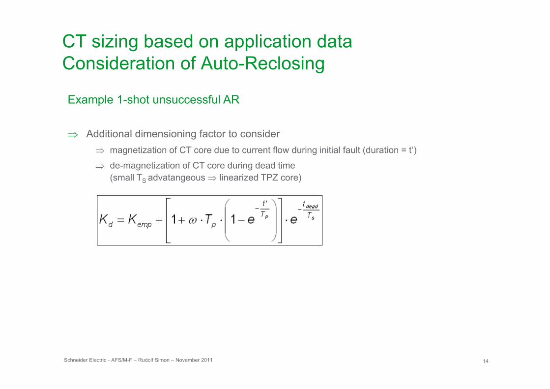
Example 1-shot unsuccessful AR
⇒ Additional dimensioning factor to consider⇒ magnetization of CT core due to current flow during initial fault (duration = t‘)⇒ magnetization of CT core due to current flow during initial fault (duration = t )
⇒ de-magnetization of CT core during dead time(small TS advatangeous ⇒ linearized TPZ core)
Schneider Electric 14- AFS/M-F – Rudolf Simon – November 2011
CT sizing based on application data
Yo r e perienceYour experience … ??????
Schneider Electric 15- AFS/M-F – Rudolf Simon – November 2011

Make the most ofMake the most of your energy™

![21052015 Methods in PhV.ppt [Compatibiliteitsmodus]Microsoft PowerPoint - 21052015_Methods in PhV.ppt [Compatibiliteitsmodus] Author lharmark Created Date 5/26/2015 8:30:18 PM ...File](https://img.pdfslide.us/doc/110x75/60c0edf041884365126d7a11/21052015-methods-in-phvppt-compatibiliteitsmodus-microsoft-powerpoint-21052015methods.jpg)
![Flyer motortreffen 2016 [Compatibiliteitsmodus] archief 2016/Flyer W… · Microsoft PowerPoint - Flyer motortreffen 2016 [Compatibiliteitsmodus] Author: geeraesb Created Date: 2/23/2016](https://img.pdfslide.us/doc/110x75/6047fe74b9507a609843a7dc/flyer-motortreffen-2016-compatibiliteitsmodus-archief-2016flyer-w-microsoft.jpg)


![breider poster.ppt [Compatibiliteitsmodus]architecturalgeometry.at/aag08/poster/vienna.pdf · Microsoft PowerPoint - breider_poster.ppt [Compatibiliteitsmodus] Author: Janwillem Created](https://img.pdfslide.us/doc/110x75/5fdd8271e7b8494f9e1dd138/breider-compatibiliteitsmodusarchitecturalgeometryataag08posterviennapdf.jpg)
![FM Contact Center Audit [Compatibiliteitsmodus]](https://img.pdfslide.us/doc/110x75/547c5428b479598e508b4636/fm-contact-center-audit-compatibiliteitsmodus.jpg)


![Simplicity year review 2013 [compatibiliteitsmodus]](https://img.pdfslide.us/doc/110x75/547b57d9b37959492b8b4d0a/simplicity-year-review-2013-compatibiliteitsmodus.jpg)
![120403 logeion m_salimans_sectormanager_brainport [compatibiliteitsmodus]](https://img.pdfslide.us/doc/110x75/5463f140b4af9f5d3f8b4750/120403-logeion-msalimanssectormanagerbrainport-compatibiliteitsmodus.jpg)

![3D-NLS Plus Use Manual(Training) [Compatibiliteitsmodus]](https://img.pdfslide.us/doc/110x75/62648edc5224444d211b919e/3d-nls-plus-use-manualtraining-compatibiliteitsmodus.jpg)


![ten handout workshop innofood kansen in wereldwijde foodmarkt[compatibiliteitsmodus]](https://img.pdfslide.us/doc/110x75/55cace9abb61ebf03a8b46f4/ten-handout-workshop-innofood-kansen-in-wereldwijde-foodmarktcompatibiliteitsmodus.jpg)
![The Coffee Network Lecture JS Critical Review February 2015 [Compatibiliteitsmodus]](https://img.pdfslide.us/doc/110x75/55cf85a1550346484b902171/the-coffee-network-lecture-js-critical-review-february-2015-compatibiliteitsmodus.jpg)
![From Itch To Solution Definitief [Compatibiliteitsmodus]](https://img.pdfslide.us/doc/110x75/55af5ae61a28ab77728b45c6/from-itch-to-solution-definitief-compatibiliteitsmodus.jpg)

![Ann cools 1 clinical exam [compatibiliteitsmodus]](https://img.pdfslide.us/doc/110x75/54c164494a795951748b45e1/ann-cools-1-clinical-exam-compatibiliteitsmodus.jpg)


![Ann cools 3 scapular rehab [compatibiliteitsmodus]](https://img.pdfslide.us/doc/110x75/556bd7aad8b42ab2138b4af1/ann-cools-3-scapular-rehab-compatibiliteitsmodus.jpg)

![pres-gifu.ppt [Compatibiliteitsmodus]eerdesign.com/images/02. PROJECTS/02. MEDIUM/pres... · Title: Microsoft PowerPoint - pres-gifu.ppt [Compatibiliteitsmodus] Author: Eer Created](https://img.pdfslide.us/doc/110x75/60514afb08557e14e30be743/pres-gifuppt-compatibiliteitsmodus-projects02-mediumpres-title-microsoft.jpg)