Embed Size (px)
Citation preview
C:10 M:3 Y:1 K:0PANTONE 649 C
C:18 M:6 Y:1 K:2PANTONE 650 C
C:100 M:71 Y:9 K:58PANTONE 648 C
RTD-15
Full Height
Rotor Turnstile
Assembly and operation manual
CONTENT
1 APPLICATION ........................................................................................................................4
2 OPERATION CONDITIONS ....................................................................................................4
3 TECHNICAL SPECIFICATIONS .............................................................................................5
4 DELIVERY SET.......................................................................................................................5 4.1 Standard delivery set......................................................................................................5 4.2 Options...........................................................................................................................7
5 DESIGN AND OPERATION ....................................................................................................7 5.1 Main features .................................................................................................................7 5.2 Design of the turnstile.....................................................................................................8 5.3 Design of the remote control panel Н-05/4 ................................................................... 11 5.4 Power supply................................................................................................................ 11 5.5 Control of the turnstile .................................................................................................. 11 5.6 Input and output control signals.................................................................................... 14 5.7 Control modes..............................................................................................................15 5.8 Operation from the remote control panel ...................................................................... 17 5.9 Operation from a wireless remote control ..................................................................... 20 5.10 Operation via an ACS controller ................................................................................... 21 5.11 Optional devices that can be connected to the turnstile ................................................ 21 5.12 Key override control ..................................................................................................... 22 5.13 Operational contingencies and feedback ...................................................................... 24
6 MARKING AND PACKAGING............................................................................................... 26
7 SAFETY REQUIREMENTS ................................................................................................... 26 7.1 Installation safety requirements .................................................................................... 26 7.2 Operational safety requirements................................................................................... 27
8 INSTALLATION..................................................................................................................... 27 8.1 General recommendations ...........................................................................................27 8.2 Installation of the turnstile.............................................................................................28 8.3 Installation of optional equipment .................................................................................34 8.4 Installation checkup......................................................................................................34
9 OPERATING THE TURNSTILE............................................................................................. 35 9.1 General ........................................................................................................................35 9.2 Choosing the operating modes.....................................................................................35 9.3 Pre-starting procedure..................................................................................................36 9.4 Troubleshooting ...........................................................................................................36
10 MAINTENANCE .................................................................................................................. 37 10.1 General ........................................................................................................................37 10.2 Maintenance works sequence ......................................................................................37
11 TRANSPORTATION AND STORAGE................................................................................. 39
APPENDIX А
Connection layout for the turnstile and optional equipment ....................................... 40
APPENDIX B
Algorithm of control signals generation .......................................................................... 42
Functional test sequence in the test mode ..................................................................... 42
APPENDIX C
Adjustment instruction for the damper of the RTD-15.2 model................................ 48
Assembly and operation manual
4
Dear Customer,
Thank you for purchasing a PERCo turnstile. Please follow instructions given in this Manual carefully, and this quality product will provide many years of trouble- free use.
The Assembly and operation Manual (the Manual) of the RTD-15 electromechanical full height rotor turnstile contains data on transportation, storage, installation, operation and maintenance of the product.
The installation and maintenance should be carried out with strict accordance to this Manual.
Abbreviations adopted in the Manual:
ACS — access control system.
1 APPLICATION
1.1. The RTD-15 electromechanical full height rotor turnstile (the turnstile) is a form of rotor gate designed for management of pedestrian flows and access control at entrance points of facilities and areas with high security requirements and necessity for full closure of the passageway.
1.2. The turnstile can operate either:
as a standalone unit from remote control panel1 or wireless remote control2;
as part of an access control system via an ACS controller3.
1.3. Two versions of the turnstile are available: the RTD-15.1 model with motorized drive unit and the RTD-15.2 model with electromechanical drive unit. As the RTD-15.1 is motorized, it offers better comfort and ease of passage, thanks to automatic rotation of the barrier wings.
The Manual contains data that refer to both RTD-15.1 and RTD-15.2 models, unless noted otherwise.
1.4. It is advisable to determine the number of the turnstiles, necessary for providing fast and convenient pedestrian passage through a checkpoint, on basis of the corresponding throughput (section 3 of the Manual).
2 OPERATION CONDITIONS
2.1. The turnstile, in accordance with the resistance to environmental exposure, complies with GOST 15150-69, Category N2 (outdoor operation under shelter).
Operation of the turnstile is allowed at ambient temperature from -40°С to +55°С and relative air humidity of up to 98% at +25°С. 1 Standard delivery set (sect. 4.1) 2 Optional accessories (sect. 4.2) 3 The turnstile can be operated from an ACS through cable connection to external devices (ACS readers and controller) not supplied by the Manufacturer. When necessary, the Customer purchases these devices themselves, arranging their installation according to the recommendations on layout, connection and operation as set forth in sections 5.2, 5.5-5.7 and 5.10, and Appendix A and B.
RTD-15 Full Height Rotor Turnstile
5
2.2. The remote control panel, in accordance with the resistance to environmental exposure, complies with GOST 15150-69, Category NF4 (operation indoors with climate control).
Operation of the remote control panel is allowed at ambient temperature from +1°С to +55°С and relative air humidity of up to 80% at 25°С.
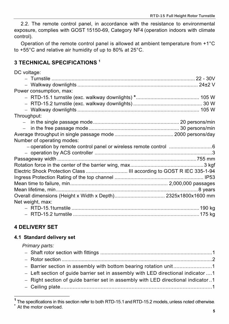
3 TECHNICAL SPECIFICATIONS 1
DC voltage: – Turnstile .................................................................................................... 22 - 30V – Walkway downlights .................................................................................... 24±2 V
Power consumption, max: – RTD-15.1 turnstile (exc. walkway downlights) *............................................ 105 W – RTD-15.2 turnstile (exc. walkway downlights) ................................................ 30 W – Walkway downlights ..................................................................................... 105 W
Throughput: – in the single passage mode............................................................ 20 persons/min – in the free passage mode ............................................................... 30 persons/min
Average throughput in single passage mode ......................................... 2000 persons/day Number of operating modes:
– operation by remote control panel or wireless remote control ..............................6 – operation by ACS controller ..................................................................................3
Passageway width .................................................................................................755 mm Rotation force in the center of the barrier wing, max...................................................3 kgf Electric Shock Protection Class ............................. III according to GOST R IEC 335-1-94 Ingress Protection Rating of the top channel .............................................................. IP53 Mean time to failure, min.................................................................... 2,000,000 passages Mean lifetime, min................................................................................................... 8 years Overall dimensions (Height х Width х Depth)................................... 2325х1800х1600 mm Net weight, max:
– RTD-15.1turnstile ......................................................................................... 190 kg – RTD-15.2 turnstile ........................................................................................ 175 kg
4 DELIVERY SET
4.1 Standard delivery set
Primary parts: – Shaft rotor section with fittings ..............................................................................1 – Rotor section .........................................................................................................2 – Barrier section in assembly with bottom bearing rotation unit .........................1 – Left section of guide barrier set in assembly with LED directional indicator ....1 – Right section of guide barrier set in assembly with LED directional indicator ..1 – Ceiling plate..................................................................................................1
1
The specifications in this section refer to both RTD-15.1 and RTD-15.2 models, unless noted otherwise. At the motor overload.
Assembly and operation manual
6
– Top channel...........................................................................................................1 – Half-coupling with fastenings.................................................................................2 – Walkway downlight ................................................................................................2 – Connector block (of 14 contacts) ...........................................................................1
– Turnstile power cable, 15 m .................................................................................1
– Walkway downlights power cable, 15 m*...............................................................1 – Control cable, 15 m*..............................................................................................1 – Left indication cable...............................................................................................1 – Right indication cable ............................................................................................1 – Remote control panel H-05/4 with cable 7 m*........................................................1 – Wire PERCo-RTD-15.842.00.................................................................................1 – Key for mechanical release lock (2 for each lock) .................................................4
Fasteners: – Bolt М8х12 ..........................................................................................................20 – Bolt М8х25 ............................................................................................................2 – Bolt М8х50 ............................................................................................................4 – Screw М6х30.......................................................................................................12 – Stud-bolt М12х65 ..................................................................................................2 – Nut М6...................................................................................................................2 – Nut М12.................................................................................................................4 – Washer 6 ...............................................................................................................2 – Washer 8 ...............................................................................................................2 – Washer 12 .............................................................................................................2 – Spring washer 8 ..................................................................................................24 – Spring washer 12 ..................................................................................................4
– Square washer...................................................................................................2
– Plate ..................................................................................................................1 – Plug Ø16 .............................................................................................................30 – Reinforcing element ..............................................................................................2 – S1.5 hex-nut wrench*** ..........................................................................................1
Spare parts: – Plug Ø16 ...............................................................................................................2
Technical documentation: – Assembly and operation manual ...........................................................................1 – Certificate ..............................................................................................................1
Package: – Package box..........................................................................................................5
Cables up to 30 m available on request. Inside top channel when delivered. *** Supplied with the RTD-15.2 for adjustment of the damper
RTD-15 Full Height Rotor Turnstile
7
4.2 Options The following equipment is available on request:
– Turnstile power supply unit ................................................................... 1 – Walkway downlights power supply unit................................................... 1 – Wireless remote control ......................................................................... 1 – Foundation frame RF01 0-01 ................................................................. 1 – Protective canopy RTC-15R ............................................................ 1 set
4.3 Mounting hardware* We advise using the following metal anchors for medium heavy and heavy fixings
in solid and hard foundations like concrete (400 grade or higher, CSC B22.5), stone, etc: – metal anchor with bolt M10x60 ..........................................................................12 – metal anchor with bolt M16x100 ...........................................................................1
(see more details in sect. 8.2.2) Installation of the turnstile on other types of foundations may require different
mounting hardware.
5 DESIGN AND OPERATION
5.1 Main features The turnstile meets current requirements to such equipment in compliance
with GOST P 51241. Main features of the turnstile: – reduced power consumption, resulting in lower operating costs (sect. 3); – safe supply voltage (sect. 3); – two options of the turnstile use: as a standalone unit operated from either remote
control panel or wireless remote control (sections 5.8, 5.9), or as part of various identification and access control systems operated via an ACS controller (sect. 5.10);
– high corrosion resistance of the turnstile aluminium frame to ensure long years of service in harsh environments;
– high durability of polymeric powder coating to keep the elegant appearance intact in intensive use conditions;
– reduced rotor weight to make the passage more comfortable; – two LED directional indicators built-in as standard, optional installation of remote
light indicators (sect. 5.11.4); – two built-in mechanical release locks to unlock the turnstile when necessary (e.g.
in the event of power failure) for free passage in either direction by means of a key (sect. 5.12);
– more comfortable passage as the entrant can walk through the turnstile at their own pace which may differ from the preset rotor speed (sect. 5.2.8);
– automatic rotation of the rotor for the RTD-15.1 model thanks to the electric gear motor;
– automatic rotor reset after each passage; – automatic unlocking of the turnstile in emergency situations from an emergency
unlocking device* (fire alarm control panel, emergency button or other similar device to send emergency unlocking signal (sect. 5.11.3));
– sound alarm on unauthorized attempts of passage when the turnstile is equipped with an intrusion detector* and a siren* (sect. 5.11.2);
Not included in the standard delivery set.
Assembly and operation manual
8
– increased control of access to a building/area by addition of video or biometric identification when the turnstile is installed for operation in the Lock-chamber access mode (sect. 5.2.11);
– fit for installation on soft ground by means of a specially designed foundation frame (sect. 8.1.2);
– as protection from exposure to the elements and an extra barrier against climbing over, a protective canopy can be optionally included in the delivery set; the canopy and the turnstile are mounted together as a single construction;
– the turnstile is a normally closed unit, i.e. the reset state of the turnstile is “closed for entry and exit” (the rotor barrier wings are locked in the home position); this is assured by the turnstile design regardless whether the power supply is on or off.
5.2 Design of the turnstile
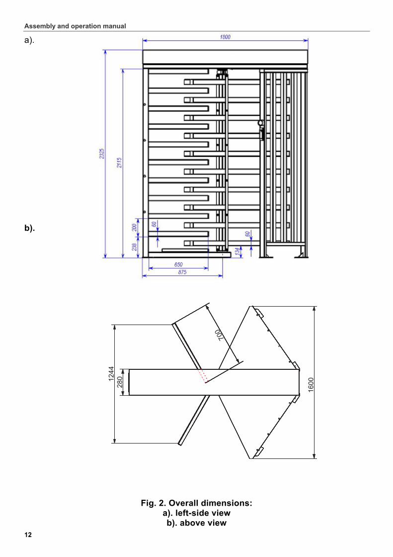
5.2.1 Design of the turnstile is shown in Fig. 1. The overall dimensions are shown in Fig. 2.
The numbers of the positions in brackets in this Manual are given according to Fig. 1, except noted otherwise.
5.2.2 The Turnstile consists of: rotor (1); barrier section (3); left guide barrier section (6); right guide barrier section (7); ceiling plate (12); top channel (13); operating mechanism; control unit.
5.2.3 The rotor (1) is an assembly of three separate sections. Each section serves as a barrier wing and consists of a vertical support with 10 welded barrier arms (2).
5.2.4 The barrier section (3) consists of a supporting post with barrier arms (2),
a flange (4), and a bottom bearing rotation unit (5) to contain the lower end of the rotor (1). The barrier section is fixed to the mounting surface through four mounting holes
in the flange and one mounting hole in the bottom bearing rotation unit. It is delivered ready-assembled.
5.2.5 Each of left (6) and right (7) guide barrier sections consists of 2 supporting posts with flanges (8) and a set of vertical security bars. The outer supporting posts are furnished with built-in LED directional indicators (9) with indication cables (10) and (11) run through and out of the posts. Each flange has 2 mounting holes for fixing the guide barrier sections to the mounting surface. Together with the rotor barrier wings, the guide barrier sections form the turnstile passageway.
5.2.6 The ceiling plate (12) is installed on top of the guide barrier set to provide stability and support, and as protection against climbing over the turnstile.
5.2.7 The top channel (13) joins the barrier section (3), the rotor (1) and the guide barrier sections (6) and (7) into a single structure, and contains the walkway downlights, the control unit and the operating mechanism. Two mechanical release locks are mounted underneath the top channel, symmetrically along its axis. Each lock is designed for unlocking the rotor in the direction of the lock’s side. The top channel is protected by a cover (14) fixed at each end of the top channel by two screws (15) with washers.
RTD-15 Full Height Rotor Turnstile
9
5.2.8 The operating mechanism is installed on a separate base inside the top channel (13). The shaft of the operating mechanism is connected to the rotor (1) shaft with the union joint (16) consisting of two half-couplings.
The operating mechanism of the RTD-15.1 model includes also an electric gear motor. In the single passage modes, at the beginning of the passage through the turnstile, the motor switches on as soon as the rotor is revolved about 12º, and makes further rotation automatic at 6 rpm in the direction of passage until the rotor is in the home position where it is securely locked (the reset of the rotor wings). In the free passage modes the motor switches into operation only to slow the rotation down as soon as the rotor turns about 108°.
The operating mechanism of the RTD-15.2 model also starts automatic rotation of the rotor (the reset of the rotor wings) as soon as the rotor has been revolved about 60º and continues rotation until the rotor is in the home position where it is securely locked.
The operating mechanism design enables the entrant to walk through the turnstile at their own pace, which may differ from the preset speed of the automatic rotation.
5.2.9 During the passage through the turnstile in a permitted direction, the reverse rotation is automatically blocked as soon as the rotor has been revolved more than 60º.
5.2.10 The control unit (the CU) is designed as a separate boxed device placed inside the top channel (13). For connection convenience all the CU connectors and terminal blocks are positioned on a DIN-rail also mounted inside the top channel (Fig.3). All cables are wired to the DIN-rail through the lower hole in the barrier section (3) from the side of the flange (4), then up the post into the top channel (Fig. 1, 3).
5.2.11 The reset state of the turnstile is “closed for entry and exit” (the passageway is closed in both directions). Two choices of the passageway closure by the barrier wings in the reset state determine available access and operating modes of the turnstile.
Access mode А: Standard rotor orientation: Only one barrier wing blocks the passageway in the reset state (Fig. 1, 12а). This access mode allows setting of standard operating modes of the turnstile (Table 1. А).
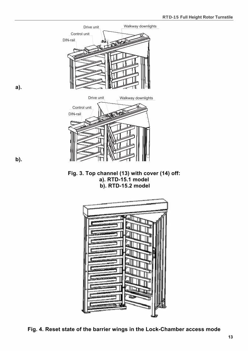
Access mode B: “Lock-Chamber” rotor orientation: The passageway in the reset state is blocked by two barrier wings (Fig. 4 and 12b) which together with the guide barrier sections form a “lock-chamber”. This access mode allows setting of Lock-Chamber operating modes (Table 1. B).
Both access modes are set at the installation stage by either rotor orientation (sect. 8.2). If later on, dependant on the operational requirements, the set access mode needs to be swapped to another, the rotor has to be reinstalled with the respective orientation (sect. 9.2).
5.2.12 The Lock-Chamber access mode option enables to reinforce control of access to buildings and areas with higher security requirements e.g. by addition of video or biometric identification.
Assembly and operation manual
10
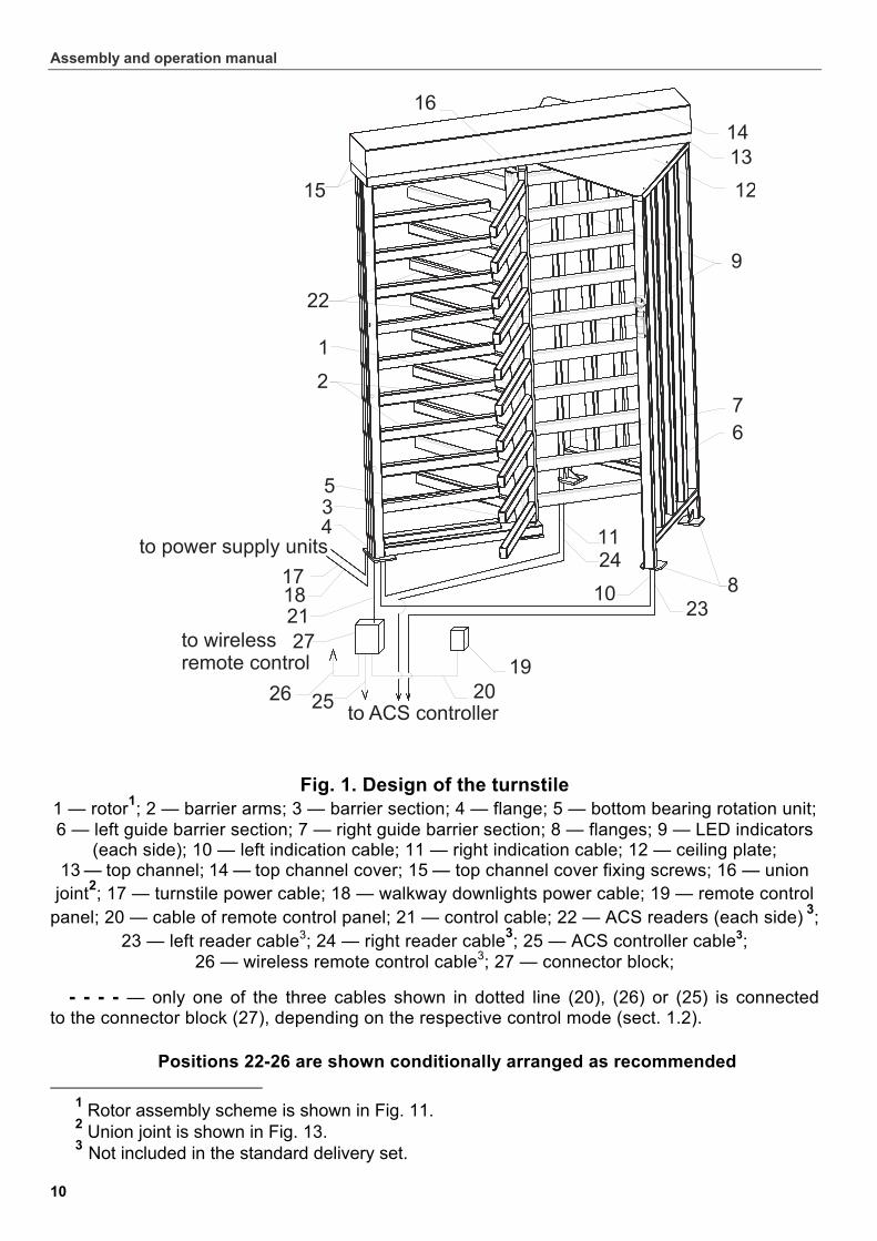
Fig. 1. Design of the turnstile
1 — rotor1; 2 — barrier arms; 3 — barrier section; 4 — flange; 5 — bottom bearing rotation unit; 6 — left guide barrier section; 7 — right guide barrier section; 8 — flanges; 9 — LED indicators
(each side); 10 — left indication cable; 11 — right indication cable; 12 — ceiling plate; 13 — top channel; 14 — top channel cover; 15 — top channel cover fixing screws; 16 — union
joint2; 17 — turnstile power cable; 18 — walkway downlights power cable; 19 — remote control panel; 20 — cable of remote control panel; 21 — control cable; 22 — ACS readers (each side) 3;
23 — left reader cable3; 24 — right reader cable3; 25 — ACS controller cable3; 26 — wireless remote control cable3; 27 — connector block;
- - - - — only one of the three cables shown in dotted line (20), (26) or (25) is connected to the connector block (27), depending on the respective control mode (sect. 1.2).
Positions 22-26 are shown conditionally arranged as recommended
1 Rotor assembly scheme is shown in Fig. 11. 2 Union joint is shown in Fig. 13. 3 Not included in the standard delivery set.
RTD-15 Full Height Rotor Turnstile
11
5.3 Design of the remote control panel Н-05/4
5.3.1 The remote control panel Н-05/4 (the control panel) serves for setting and indication of the operating modes when the turnstile is manually controlled.
5.3.2 The control panel is designed as a compact desktop device in a shockproof plastic case.
5.3.3 Three buttons on the front panel of the control panel are used to set the operating modes (Table 1). The corresponding light indicators are positioned above the buttons.
The STOP button in the middle is for switching the turnstile into the "Always locked" mode (red light indicator). The left and right buttons (green light indicators) are for unlocking the turnstile for passage in the corresponding direction. The left - right orientation is considered as seen from outside the guide barrier set.
5.3.4 The control panel is equipped with a buzzer for audible alarms. 5.3.5 The control panel is wired to the connector block (27) by the control panel
multicore cable (20).
5.4 Power supply
5.4.1 The turnstile and walkway downlights use 24±2 V DC from external power supply units. The turnstile can use power supply units with output voltages 22-30V. The walkway downlights can use ONLY power supply units with output voltage 24±2 V.
5.4.2 The turnstile is connected to its power supply unit with the turnstile power cable (17), ref. Appendix А, Fig. А.1.
5.4.3 The walkway downlights are connected to their power supply unit with the walkway downlights power cable (18), ref. Appendix А, Fig. А.1).
5.5 Control of the turnstile
5.5.1 The turnstile can be operated from: – remote control panel;
– wireless remote control*;
– ACS controller*. 5.5.2 The above devices can be connected to the turnstile ONLY separately.
An ACS controller and the control panel (a wireless remote control) must not be connected to the turnstile simultaneously.
5.5.3 The turnstile design enables mounting of ACS readers (22) on the supporting posts of the guide barrier sections. The readers’ position and the cable layout are shown in Fig. 1 and 8.
An ACS controller is connected to the turnstile with the ACS controller cable (25), wired to the connector block (27).
* Not included in the standard delivery set.
Assembly and operation manual
12
a).
b).
Fig. 2. Overall dimensions:
a). left-side view b). above view
RTD-15 Full Height Rotor Turnstile
13
а).
b).
Fig. 3. Top channel (13) with cover (14) off: а). RTD-15.1 model b). RTD-15.2 model
Fig. 4. Reset state of the barrier wings in the Lock-Chamber access mode
Assembly and operation manual
14
Operation from an ACS requires installation of a jumper (the «IMPULS» jumper, not factory-installed) on the DIN-rail by means of the wire RTD-15.842.00 from the standard delivery set (Appendix А, Fig. А.1), between the «IMPULS» connector 15 and «GND» connector 16.
5.5.4 The control panel is connected to the turnstile through the cable (20), wired to the connector block (27). Operation from the control panel requires the «IMPULS» jumper uninstalled (sect. 5.5.3 and Appendix А, Fig. А.1).
5.5.5 The above devices should be connected to the respective connectors of the DIN-rail according to Fig. А.1 of Appendix А:
– the control panel is wired to the connectors 7-14 («GND», «Unlock A», «Stop», «Unlock B», «RSLed A», «RS Stop», «RSSound» and «RSLed B»);
– a wireless remote control is wired to the connectors 7, 9, 10, 11 («GND»,
«Unlock A», «Stop» and «Unlock B»); a wireless remote control power supply is wired to the connector 17 «+12V»;
– outputs of an ACS controller are wired to the connectors 7, 9, 10, 11 («GND», «Unlock A», «Stop» and «Unlock B»);
– inputs of an ACS controller are wired to the connectors 20-24 («Common», «PASS A», «PASS B», «Ready» and «Det Out»).
Connectors’ assignment is shown on the DIN-rail.
5.6 Input and output control signals
5.6.1 The control unit microcontroller (the CU microcontroller) processes incoming commands (i.e. status of the contacts «Unlock A», «Stop», «Unlock B», «Fire Alarm»); keeps track of the signals from the optical rotation sensors, optical sensors of the locking device, and from an intrusion detector (the «Detector» contact). Basing on these signals, the microcontroller generates commands to the operating mechanism and signals to the external devices («RS Led A», «RS Led Stop», «RS Led B» indication on the control panel; «PASS А»/«PASS В» signal of the rotor rotation in the respective direction; «Ready» operation contingency signal; «Alarm» signal), and relays the current status of the intrusion detector («Det Out»).
5.6.2 The turnstile is operated by input of a low-level signal relative to the «GND» contact at the DIN-rail contacts 9…11 («Unlock A», «Stop» and «Unlock B»). Either a normally open relay contact or a circuit with open-collector output can be used as the control element.
Emergency unlocking of the turnstile is realized by removal of the low-level signal relative to the «GND» contact from the «Fire Alarm» contact. Acting as the control element can be either a normally closed relay contact or an open-collector circuit (Fig. 5).
Note. As means of a high-level signal generation at all the input contacts («Stop», «Unlock A», Unlock B», «Fire Alarm», «Detector»), the control unit uses 2-KOHm resistors wired to the power supply bus «+ 5 V».
5.6.3 The control element should provide the following signal characteristics: а) a relay contact as the control element (Fig. 5а): – minimum switched current..................................................................................3 mА; – maximum closed contact resistance (with the connecting cable resistance)..... 300 Оhm; b). a circuit with open-collector output as the control element (Fig. 5b): – maximum voltage at the closed contact (low-level signal at the control unit input) .. 0.8 V.
RTD-15 Full Height Rotor Turnstile
15
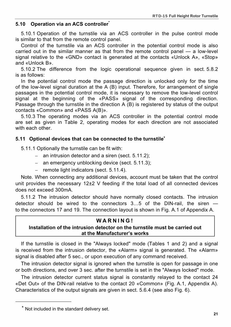
5.6.4 The relays «PASS A» (contacts 21 «PASS A» and 20 «Common»), «PASS B» (contacts 22 «PASS В» and 20 «Common»), «Ready» (contacts 23 «Ready» and 20 «Common»), «Detector» (contacts 24 «Det Out» and 20 «Common») and «Alarm» (contacts 18 «Alarm 1» and 19 «Alarm 2») have normally open contacts. Their common contact («Common») is not wired to the negative terminal of the turnstile power supply unit.
In the initial (inactive) state when the power is on, the relay contacts «PASS A», «PASS B», «Ready» и «Detector» are closed (voltage supplied to the relay coil), while the relay contacts «Alarm» are open (no voltage to the relay coil).
The output stages for «PASS A», «PASS B», «Ready», «Det Out» и «Alarm» are the relay contacts with the following signal characteristics (Fig. 6):
– maximum commutation voltage......................................................................... 42V
– maximum switched current ........................................................................... 0.25 А
– maximum closed contact resistance .......................................................0.15 Ohm.
5.7 Control modes
5.7.1 Two control modes, pulse and potential, are available. These control modes determine available operating modes of the turnstile (Tables 1 and 2).
Either control mode is set by the «IMPULS» jumper on the DIN-rail (sect. 5.5.3):
- if there is no jumper, the turnstile is operated in the pulse control mode;
- the installed jumper results in the potential control mode.
In both control modes the turnstile is operated by input of the control signal. The passage waiting time in the pulse control mode is 5 sec. regardless of the control signal (pulse) length. In the potential mode the passage waiting time equals the control signal length.
5.7.2 The pulse control mode is used for control of the turnstile from the control panel, a wireless remote control, or via an ACS controller with outputs supporting pulse control mode.
Standard control inputs: connectors 9…11 of the DIN-rail («Unlock A», «Stop» and «Unlock B»).
Special control input: connector 6 of the DIN-rail («Fire Alarm»). The turnstile operating modes in the pulse control modes are shown
in Table 1. The control signals sequence is given in section B.1 of Appendix B. The minimum input signal duration to change one operating mode for another
is 100 ms. The passage waiting time is 5 sec. irrespective of an input signal length. Operation at the special «Fire Alarm» control input is given in sect. 5.11. 5.7.3 The potential control mode is used for control of the turnstile via an ACS
controller with outputs supporting potential control mode. Standard control inputs: connectors 9 and 11 of the DIN-rail («Unlock A»
and «Unlock B»). Special control inputs: connectors 10 («Stop») and 6 («Fire Alarm»). The turnstile operating modes in the potential control mode are shown in Table 2, the
control signals sequence is given in section B.2 of Appendix B.

Assembly and operation manual
16
а).
b).
Рис. 5. ACS control elements:
а). normally open relay contact
b). circuit with open-collector output
RTD-15 Full Height Rotor Turnstile
17
The minimum input signal duration to change one operation mode for another is 100 ms. The passage waiting time equals a low-level signal duration (the turnstile remains open if upon completion of the passage there is still a low-level signal at the input for the permitted direction).
When a low-level signal is received to the «Stop» input, both directions close for as long as the signal is present, regardless of signal levels at the «Unlock A» and «Unlock B» inputs. When the low signal is removed from the «Stop» input, status of each direction is determined by respective signal levels at the «Unlock A» and «Unlock B» inputs.
Operation of the turnstile from the special «Fire Alarm» control input is given in sect. 5.11.
5.8 Operation from the remote control panel
5.8.1 Press of the buttons on the remote control panel (the «STOP» button and one button for each direction) results in closing of respective contacts «Unlock A», «Stop» or «Unlock B» with the «GND» contact (i.e. generation of a low-level signal relative to the «GND» contact).
5.8.2 Logic operational sequence at the single passage in direction А (В), the pulse control mode (the «Single passage in the set direction» operating mode):
– press of the button responsible for opening of direction А (В) results in closing of the «Unlock A (В)» contact with the «GND» contact (i.e. generation of a low-level signal relative to the «GND» contact at the «Unlock A(В)» contact);
– the CU microcontroller processes the incoming command and generates a command to the locking device of the operating mechanism to unlock the passage in direction А(В);
– the CU microcontroller keeps track of the optical rotation sensors status that are activated / inactivated in a certain sequence during the rotor rotation, and counts the time from press of the button responsible for opening of direction А (В);
– if the passage (revolving of the rotor) does not commence over 5 seconds from the moment of the button press, the CU microcontroller generates a command to the operating mechanism to lock the passageway in direction А(В);
– after the rotor turns 12°30´, the control unit of the RTD-15.1 generates a command for automatic rotation in the set direction (the motor switches into operation); the operating mechanism of the RTD-15.2 begins turning the rotor in the direction of passage as soon as the rotor turns more than 60º ;
– when the rotor is revolved 67°, the CU microcontroller generates the «PASS А(В)» signal (opening of the contacts «PASS А(В)» and «Common» occurs);
– when the rotor is revolved 112°, the CU microcontroller removes the «PASS А(В)» signal (closing of the contacts «PASS А(В)» and «Common»); the barrier wings reset.
Note. Operation in the free passage modes, either in one or both directions, differs from the above in that respect that the passageway in the permitted direction remains open (unlocked) for the next passage.
As far as RTD-15.1 is concerned, there is no motor operation to turn the rotor automatically when the rotor is turned 12°30´, rather the control unit generates a command to slow the rotation down as soon as the rotor turns about 108°.
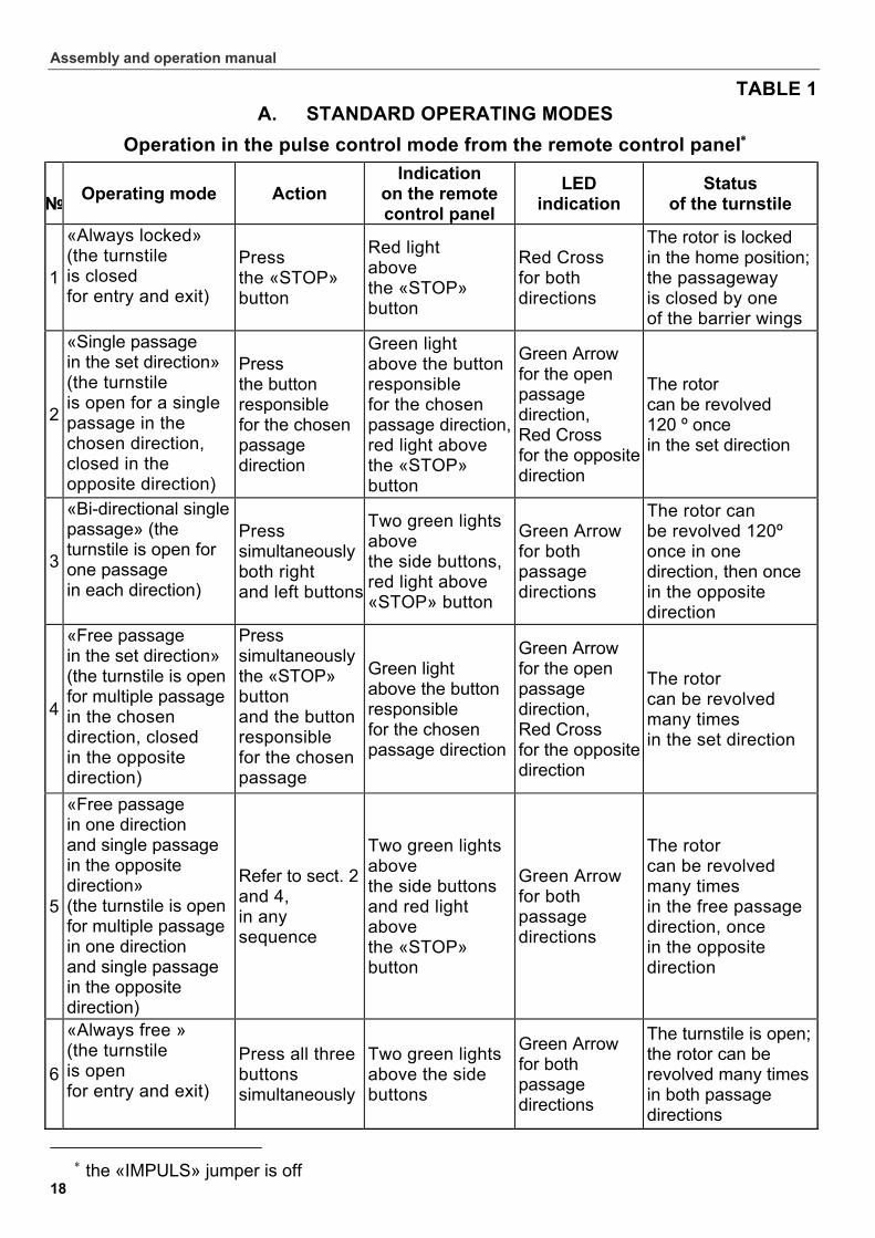
5.8.3 The operating modes in the pulse control mode are set from the remote control panel as given in Table 1, operating modes for each direction are not associated with each other.
Assembly and operation manual
18
TABLE 1 А. STANDARD OPERATING MODES
Operation in the pulse control mode from the remote control panel
№
Operating mode Action Indication
on the remote control panel
LED indication
Status of the turnstile
1
«Always locked» (the turnstile is closed for entry and exit)
Press the «STOP» button
Red light above the «STOP» button
Red Cross for both directions
The rotor is locked in the home position; the passageway is closed by one of the barrier wings
2
«Single passage in the set direction» (the turnstile is open for a single passage in the chosen direction, closed in the opposite direction)
Press the button responsible for the chosen passage direction
Green light above the button responsible for the chosen passage direction, red light above the «STOP» button
Green Arrow for the open passage direction, Red Cross for the opposite direction
The rotor can be revolved 120 º once in the set direction
3
«Bi-directional single passage» (the turnstile is open for one passage in each direction)
Press simultaneously both right and left buttons
Two green lights above the side buttons, red light above «STOP» button
Green Arrow for both passage directions
The rotor can be revolved 120º once in one direction, then once in the opposite direction
4
«Free passage in the set direction» (the turnstile is open for multiple passage in the chosen direction, closed in the opposite direction)
Press simultaneously the «STOP» button and the button responsible for the chosen passage di ti
Green light above the button responsible for the chosen passage direction
Green Arrow for the open passage direction, Red Cross for the opposite direction
The rotor can be revolved many times in the set direction
5
«Free passage in one direction and single passage in the opposite direction» (the turnstile is open for multiple passage in one direction and single passage in the opposite direction)
Refer to sect. 2 and 4, in any sequence
Two green lights above the side buttons and red light above the «STOP» button
Green Arrow for both passage directions
The rotor can be revolved many times in the free passage direction, once in the opposite direction
6
«Always free » (the turnstile is open for entry and exit)
Press all three buttons simultaneously
Two green lights above the side buttons
Green Arrow for both passage directions
The turnstile is open; the rotor can be revolved many times in both passage directions
the «IMPULS» jumper is off
RTD-15 Full Height Rotor Turnstile
19
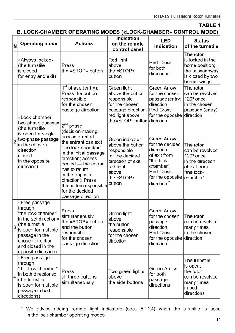
TABLE 1 B. LOCK-CHAMBER OPERATING MODES («LOCK-CHAMBER» CONTROL MODE)
№
Operating mode Actions Indication
on the remote control panel
LED indication
Status of the turnstile
1
«Always locked» (the turnstile is closed for entry and exit)
Press the «STOP» button
Red light above the «STOP» button
Red Cross for both directions
The rotor is locked in the home position; the passageway is closed by two barrier wings
1st phase (entry): Press the button responsible for the chosen passage direction
Green light above the button responsible for the chosen passage direction, red light above the «STOP» button
Green Arrow for the chosen passage (entry) direction, Red Cross for the opposite direction
The rotor can be revolved 120º once in the chosen passage (entry) direction
2
«Lock-chamber two-phase access» (the turnstile is open for single two-phase passage in the chosen direction, closed in the opposite direction)
2nd phase (decision-making: access granted — the entrant can exit “the lock-chamber” in the initial passage direction; access denied — the entrant has to return in the opposite direction): Press the button responsiblefor the decided passage direction
Green indicator above the button responsible for the decided direction of exit, red light above the «STOP» button
Green Arrow for the decided direction of exit from “the lock-chamber”, Red Cross for the opposite direction
The rotor can be revolved 120º once in the direction of exit from “the lock-chamber”
3
«Free passage through “the lock-chamber” in the set direction» (the turnstile is open for multiple passage in the chosen direction and closed in the opposite direction)
Press simultaneously the «STOP» button and the button responsible for the chosen passage direction
Green light above the button responsible for the chosen direction
Green Arrow for the chosen passage direction, Red Cross for the opposite direction
The rotor can be revolved many times in the chosen direction
4
«Free passage through “the lock-chamber” in both directions» (the turnstile is open for multiple passage in both directions)
Press all three buttons simultaneously
Two green lights above the side buttons
Green Arrow for both passage directions
The turnstile is open; the rotor can be revolved many times in both directions
We advice adding remote light indicators (sect. 5.11.4) when the turnstile is used
in the lock-chamber operating modes.
Assembly and operation manual
20
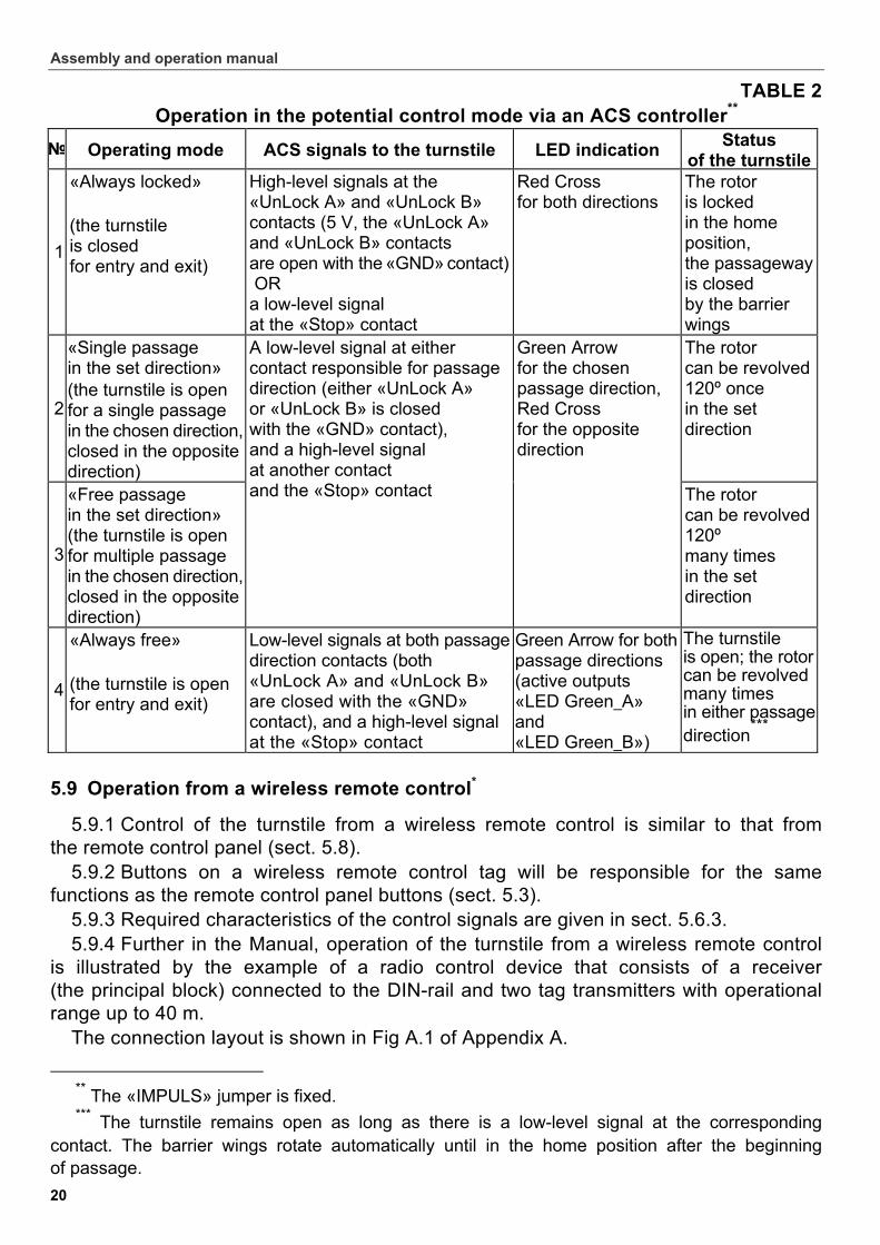
TABLE 2 Operation in the potential control mode via an ACS controller**
№ Operating mode ACS signals to the turnstile LED indication Status
of the turnstile
1
«Always locked» (the turnstile is closed for entry and exit)
High-level signals at the «UnLock A» and «UnLock B» contacts (5 V, the «UnLock A» and «UnLock B» contacts are open with the «GND» contact) OR a low-level signal at the «Stop» contact
Red Cross for both directions
The rotor is locked in the home position, the passageway is closed by the barrier wings
2
«Single passage in the set direction» (the turnstile is open for a single passage in the chosen direction, closed in the opposite direction)
The rotor can be revolved 120º once in the set direction
3
«Free passage in the set direction» (the turnstile is open for multiple passage in the chosen direction, closed in the opposite direction)
A low-level signal at either contact responsible for passage direction (either «UnLock A» or «UnLock B» is closed with the «GND» contact), and a high-level signal at another contact and the «Stop» contact
Green Arrow for the chosen passage direction, Red Cross for the opposite direction
The rotor can be revolved 120º many times in the set direction
4
«Always free» (the turnstile is open for entry and exit)
Low-level signals at both passagedirection contacts (both «UnLock A» and «UnLock B» are closed with the «GND» contact), and a high-level signal at the «Stop» contact
Green Arrow for both passage directions (active outputs «LED Green_A» and «LED Green_B»)
The turnstile is open; the rotorcan be revolved many times in either passagedirection
***
5.9 Operation from a wireless remote control*
5.9.1 Control of the turnstile from a wireless remote control is similar to that from the remote control panel (sect. 5.8).
5.9.2 Buttons on a wireless remote control tag will be responsible for the same functions as the remote control panel buttons (sect. 5.3).
5.9.3 Required characteristics of the control signals are given in sect. 5.6.3. 5.9.4 Further in the Manual, operation of the turnstile from a wireless remote control
is illustrated by the example of a radio control device that consists of a receiver (the principal block) connected to the DIN-rail and two tag transmitters with operational range up to 40 m.
The connection layout is shown in Fig А.1 of Appendix А.
** The «IMPULS» jumper is fixed. *** The turnstile remains open as long as there is a low-level signal at the corresponding
contact. The barrier wings rotate automatically until in the home position after the beginning of passage.
*Not included in the standard delivery set.
RTD-15 Full Height Rotor Turnstile
21
5.10 Operation via an ACS controller*
5.10.1 Operation of the turnstile via an ACS controller in the pulse control mode is similar to that from the remote control panel.
Control of the turnstile via an ACS controller in the potential control mode is also carried out in the similar manner as that from the remote control panel — a low-level signal relative to the «GND» contact is generated at the contacts «Unlock A», «Stop» and «Unlock B».
5.10.2 The difference from the logic operational sequence given in sect. 5.8.2 is as follows:
In the potential control mode the passage direction is unlocked only for the time of the low-level signal duration at the A (B) input. Therefore, for arrangement of single passages in the potential control mode, it is necessary to remove the low-level control signal at the beginning of the «PASS» signal of the corresponding direction. Passage through the turnstile in the direction А (В) is registered by status of the output contacts «Common» and «PASS A(В)».
5.10.3 The operating modes via an ACS controller in the potential control mode are set as given in Table 2, operating modes for each direction are not associated with each other.
5.11 Optional devices that can be connected to the turnstile
5.11.1 Optionally the turnstile can be fit with:
– an intrusion detector and a siren (sect. 5.11.2);
– an emergency unblocking device (sect. 5.11.3);
– remote light indicators (sect. 5.11.4).
Note. When connecting any additional devices, account must be taken that the control unit provides the necessary 12±2 V feeding if the total load of all connected devices does not exceed 300mA.
5.11.2 The intrusion detector should have normally closed contacts. The intrusion detector should be wired to the connectors 3…5 of the DIN-rail, the siren — to the connectors 17 and 19. The connection layout is shown in Fig. А.1 of Appendix А.
If the turnstile is closed in the "Always locked" mode (Tables 1 and 2) and a signal is received from the intrusion detector, the «Alarm» signal is generated. The «Alarm» signal is disabled after 5 sec., or upon execution of any command received.
The intrusion detector signal is ignored when the turnstile is open for passage in one or both directions, and over 3 sec. after the turnstile is set in the "Always locked" mode.
The intrusion detector current status signal is constantly relayed to the contact 24 «Det Out» of the DIN-rail relative to the contact 20 «Common» (Fig. А.1, Appendix А). Characteristics of the output signals are given in sect. 5.6.4 (see also Fig. 6).
* Not included in the standard delivery set.
Not included in the standard delivery set.
W A R N I N G ! Installation of the intrusion detector on the turnstile must be carried out
at the Manufacturer’s works

Assembly and operation manual
22
5.11.3 For immediate unlocking of the turnstile in the event of an emergency, an emergency unblocking device can be connected to the turnstile (e.g. fire alarm control panel, emergency button or other similar device to send «Fire Alarm» signal). The connection is carried out to the contacts 6 and 7 of the DIN-rail («Fire Alarm» and «GND») according to Fig. А.1 of Appendix А.
If the turnstile is not meant to work with an emergency unblocking device, it is necessary to fix a jumper between the contacts 6 and 7 of the DIN-rail by means of the wire RTD-15.842.00 (the «Fire Alarm» jumper). The «Fire Alarm» jumper is factory-installed.
Operation from an emergency unlocking device: – in the pulse control mode: when a low-level signal is removed from the «Fire Alarm»
input, both passage directions are opened for duration of the signal removal, all other commands are ignored; when a low-level is returned to the «Fire Alarm» output, the turnstile switches to the "Always locked" mode;
– in the potential control mode: when a low-level signal is removed from the «Fire Alarm» input, both passage directions are opened for duration of the signal removal, all other commands are ignored; when a low-level signal is returned to the «Fire Alarm» input, status of the passage directions is determined by signal levels at the contacts «Unlock A», «Unlock B» and «Stop».
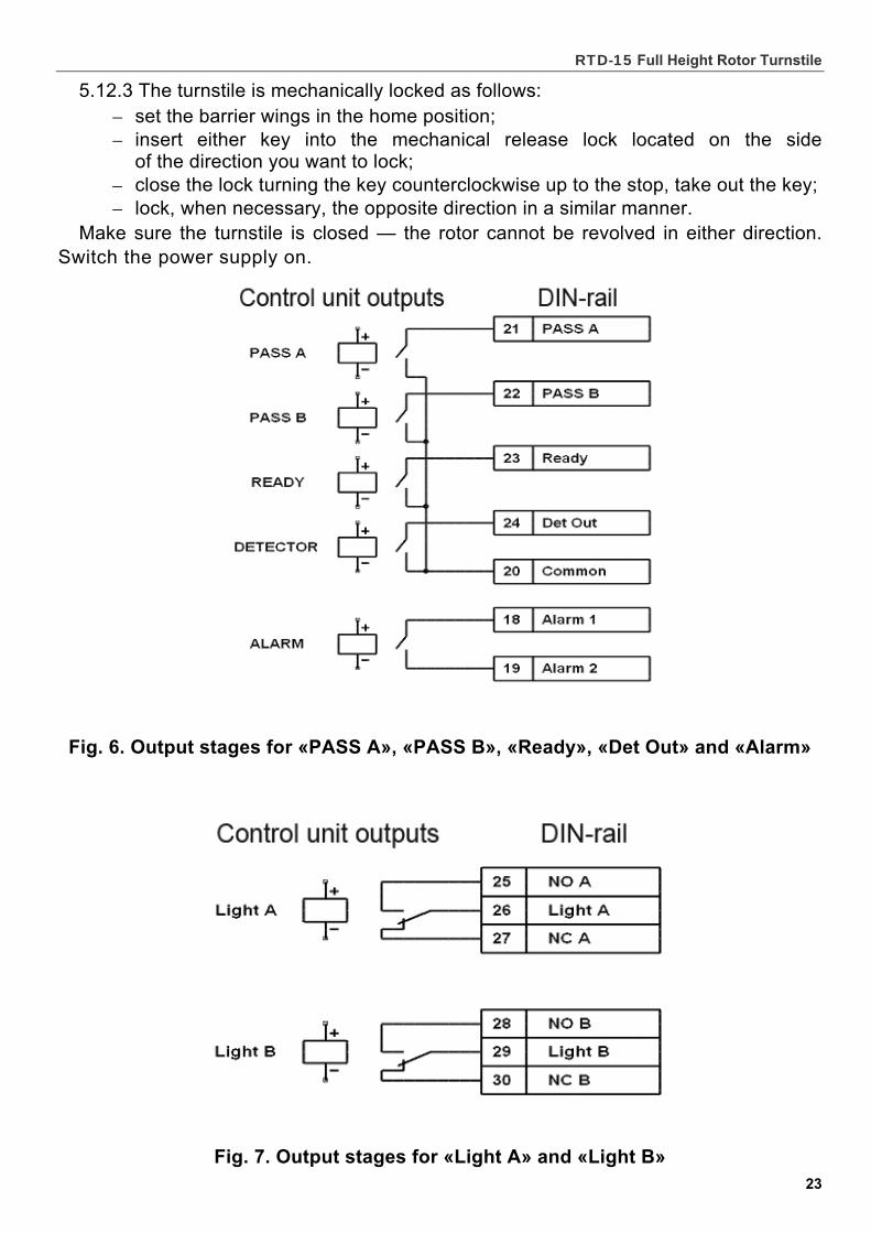
5.11.4 Remote light indicators can be connected to the DIN-rail connectors 25…30. The «Green Arrow» on the LED display, corresponding to the set passage direction,
indicates that the «Light A» («Light B») relay is activated (voltage on the relay coil). The «Red Cross» indicates that it is inactivated (no voltage on the relay coil).
Output stages for «Light A» and «Light B» are brake-make relay contacts (Fig. 7) with the following signal characteristics:
– maximum DC switched voltage..................................................................30 V – maximum AC switched current voltage ......................................................42 V – maximum switched AC/DC ..........................................................................3 А – maximum closed contact resistance ..................................................0,15 Ohm
5.12 Key override control
5.12.1 This feature is designed for fast unlocking of the turnstile in emergency situations e.g. in the event of a fire, natural or industrial disaster, power failures or interruptions, etc.
Two mechanical release locks are symmetrically mounted along the top channel axis (13) and accessible from the passageway below. Each lock is designed for unlocking the rotor (1) in the direction of the lock’s side, independently of the other direction.
5.12.2 Follow the below steps to unlock the turnstile mechanically: – make sure the power supply unit is de-energized (switch the power supply off); – insert either key into the mechanical release lock located on the side
of the direction you want to unlock; – open the lock turning the key clockwise up to the stop; – unlock, when necessary, the opposite direction in a similar manner.
Make sure the turnstile is open by revolving the rotor a few times in the desired direction.
C A U T I O N !
Do not use the mechanically unlocked turnstile unless the power is off as it may result in damage of the operating mechanism and the CU.
RTD-15 Full Height Rotor Turnstile
23
5.12.3 The turnstile is mechanically locked as follows: – set the barrier wings in the home position; – insert either key into the mechanical release lock located on the side
of the direction you want to lock; – close the lock turning the key counterclockwise up to the stop, take out the key; – lock, when necessary, the opposite direction in a similar manner.
Make sure the turnstile is closed — the rotor cannot be revolved in either direction. Switch the power supply on.
Fig. 6. Output stages for «PASS A», «PASS B», «Ready», «Det Out» and «Alarm»
Fig. 7. Output stages for «Light A» and «Light B»
Assembly and operation manual
24
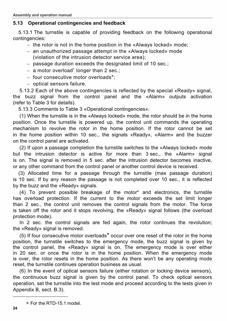
5.13 Operational contingencies and feedback
5.13.1 The turnstile is capable of providing feedback on the following operational contingencies:
– the rotor is not in the home position in the «Always locked» mode; – an unauthorized passage attempt in the «Always locked» mode
(violation of the intrusion detector service area); – passage duration exceeds the designated limit of 10 sec.; – a motor overload longer than 2 sec.; – four consecutive motor overloads*; – optical sensors failure.
5.13.2 Each of the above contingencies is reflected by the special «Ready» signal, the buzz signal from the control panel and the «Alarm» outputs activation (refer to Table 3 for details).
5.13.3 Comments to Table 3 «Operational contingencies»: (1) When the turnstile is in the «Always locked» mode, the rotor should be in the home
position. Once the turnstile is powered up, the control unit commands the operating mechanism to revolve the rotor in the home position. If the rotor cannot be set in the home position within 10 sec., the signals «Ready», «Alarm» and the buzzer on the control panel are activated.
(2) If upon a passage completion the turnstile switches to the «Always locked» mode but the intrusion detector is active for more than 3 sec., the «Alarm» signal is on. The signal is removed in 5 sec. after the intrusion detector becomes inactive, or any other command from the control panel or another control device is received.
(3) Allocated time for a passage through the turnstile (max passage duration) is 10 sec. If by any reason the passage is not completed over 10 sec., it is reflected by the buzz and the «Ready» signals.
(4) To prevent possible breakage of the motor* and electronics, the turnstile has overload protection. If the current to the motor exceeds the set limit longer than 2 sec., the control unit removes the control signals from the motor. The force is taken off the rotor and it stops revolving, the «Ready» signal follows (the overload protection mode).
In 2 sec. the control signals are fed again, the rotor continues the revolution; the «Ready» signal is removed.
(5) If four consecutive motor overloads* occur over one reset of the rotor in the home position, the turnstile switches to the emergency mode, the buzz signal is given by the control panel, the «Ready» signal is on. The emergency mode is over either in 20 sec. or once the rotor is in the home position. When the emergency mode is over, the rotor resets in the home position. As there won’t be any operating mode reset, the turnstile continues operation business as usual.
(6) In the event of optical sensors failure (either rotation or locking device sensors), the continuous buzz signal is given by the control panel. To check optical sensors operation, set the turnstile into the test mode and proceed according to the tests given in Appendix B, sect. B.3).
For the RTD-15.1 model.
RTD-15 Full Height Rotor Turnstile
25
When one of the passage directions is unlocked, in order to release stoppers of the locking device, the rotor can be slightly revolved within 1 from the home position.
In the event of failure of one of the optical sensors of the locking device when the rotor is in the home position, the turnstile* can switch into the overload protection mode (ref. to (4)).
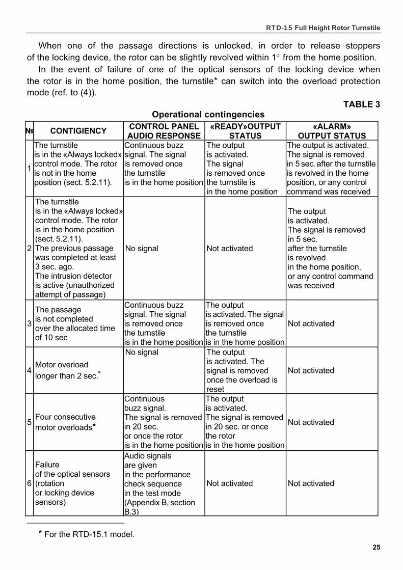
TABLE 3 Operational contingencies
№ CONTIGIENCY CONTROL PANEL AUDIO RESPONSE
«READY»OUTPUT STATUS
«ALARM» OUTPUT STATUS
1
The turnstile is in the «Always locked» control mode. The rotor is not in the home position (sect. 5.2.11).
Continuous buzz signal. The signal is removed once the turnstile is in the home position
The output is activated. The signal is removed once the turnstile is in the home position
The output is activated. The signal is removed in 5 sec. after the turnstile is revolved in the home position, or any control command was received
2
The turnstile is in the «Always locked» control mode. The rotor is in the home position (sect. 5.2.11). The previous passage was completed at least 3 sec. ago. The intrusion detector is active (unauthorized attempt of passage)
No signal Not activated
The output is activated. The signal is removed in 5 sec. after the turnstile is revolved in the home position, or any control command was received
3
The passage is not completed over the allocated time of 10 sec
Continuous buzz signal. The signal is removed once the turnstile is in the home position
The output is activated. The signal is removed once the turnstile is in the home position
Not activated
4 Motor overload longer than 2 sec.
No signal The output is activated. The signal is removed once the overload is reset
Not activated
5 Four consecutive motor overloads*
Continuous buzz signal. The signal is removed in 20 sec. or once the rotor is in the home position
The output is activated. The signal is removed in 20 sec. or once the rotor is in the home position
Not activated
6
Failure of the optical sensors (rotation or locking device sensors)
Audio signals are given in the performance check sequence in the test mode (Appendix B, section B.3)
Not activated Not activated
* For the RTD-15.1 model. For the RTD-15.1 model.
Assembly and operation manual
26
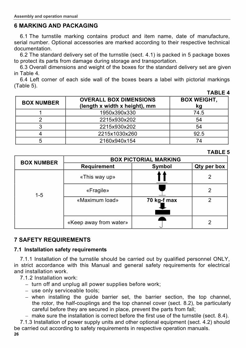
6 MARKING AND PACKAGING
6.1 The turnstile marking contains product and item name, date of manufacture, serial number. Optional accessories are marked according to their respective technical documentation.
6.2 The standard delivery set of the turnstile (sect. 4.1) is packed in 5 package boxes to protect its parts from damage during storage and transportation.
6.3 Overall dimensions and weight of the boxes for the standard delivery set are given in Table 4.
6.4 Left corner of each side wall of the boxes bears a label with pictorial markings (Table 5).
TABLE 4
BOX NUMBER OVERALL BOX DIMENSIONS (length х width х height), mm
BOX WEIGHT, kg
1 1950x390x330 74.5 2 2215х930х202 54 3 2215х930х202 54 4 2215х1030х260 92.5 5 2160x940x154 74
TABLE 5 BOX PICTORIAL MARKING
BOX NUMBER Requirement Symbol Qty per box
«This way up» 2
«Fragile» 2
«Maximum load» 70 kg-f max
2 1-5
«Keep away from water»
2
7 SAFETY REQUIREMENTS
7.1 Installation safety requirements
7.1.1 Installation of the turnstile should be carried out by qualified personnel ONLY, in strict accordance with this Manual and general safety requirements for electrical and installation work.
7.1.2 Installation work: – turn off and unplug all power supplies before work; – use only serviceable tools; – when installing the guide barrier set, the barrier section, the top channel,
the rotor, the half-couplings and the top channel cover (sect. 8.2), be particularly careful before they are secured in place, prevent the parts from fall;
– make sure the installation is correct before the first use of the turnstile (sect. 8.4). 7.1.3 Installation of power supply units and other optional equipment (sect. 4.2) should
be carried out according to safety requirements in respective operation manuals.
RTD-15 Full Height Rotor Turnstile
27
7.2 Operational safety requirements
7.2.1 Observe general safety requirements for use of electrical equipment. 7.2.2 The turnstile MUST NOT be used:
– in conditions different from those given in sect. 2; – with supply voltage different from that given in sect. 3.
7.2.3 Power supply units and other optional equipment (sect. 4.2) should be used according to safety requirements given in their respective operation manuals.
7.2.4 Servicing work: – turn off and unplug all power supplies before work; – be careful when taking off and on bulky and heavy parts such as the top channel
cover, half-couplings, rotor (sect. 10.2) and make extra sure to prevent them from fall.
8 INSTALLATION
8.1 General recommendations
8.1.1 Proper installation is critical to performance and serviceability of the turnstile. We strongly advise to study this section before installation work, and follow the instructions to the letter.
8.1.2 We advise: – installation to be carried out by at least two persons qualified in assembly
and electric work; – mount the turnstile on flat, solid concrete floors (grade 400 or higher, SCS B22.5),
stone or similar foundations at least 150 mm thick; – employ reinforcing elements 500х500х500 mm or a foundation frame (see
comments below) for soft ground; – make sure the mounting foundation is horizontal and flat; the flatness deviation
must not exceed 1,5 mm; – use mounting hardware as recommended in sect. 4.3; – optional equipment to be installed according to the above recommendations,
in sequence given in sect. 8.3. Note. Use of a foundation frame removes the necessity of marking mounting holes
and anchor installation, increases the whole soundness of the turnstile attachment. 8.1.3 We advise to use the following tools for the installation work:
– 1,21,5 кW electric perforator ; – 16 mm and 25 mm carbide drill bits; – S7; S8; S10; S13; S17; S19; S24 horn wrenches; – S7; S8; S10; S13; S17; S19; S24 box spanners; – S1,5; S2; S4; S6; S14 hex-nut wrenches – №2 cross-tip screwdriver, 150 mm; – №5 straight- slot screwdriver, 150 mm; – pair of trammels;
WARNING! The manufacturer will not accept liability for any damage to the turnstile
or other equipment, or otherwise loss caused as a result of improper installation, and will dismiss any claims by the customer should the installation
work be carried out not in accordance with this Operation Manual
Assembly and operation manual
28
– 3 m tape-measure; – level gauge; – dynamometer or household spring balance up to 10 kgf; – 0,5 mm х 2,5m wire (pull-out wire); – scotch tape; – two stepladders (4 steps or more).
Note. Use of other similar tools is allowed providing they do not reduce quality of the installation work.
8.2 Installation of the turnstile
8.2.1 Unpack the turnstile, check the delivery set against section 3 of the Certificate.
8.2.2 Recommendations how to prepare mounting holes in the foundation (the mounting surface) are given with regard to anchor bolts for solid concrete floors or similar foundations (sect. 4.2.3, 8.1.2, Table 6 and Fig.8). Use relevant mounting hardware for installation on different foundations.
TABLE 6
ANCHOR TYPE
PURPOSE DRILL BIT DIAMETER, mm
DRILLING DEPTH, mm
QTY
M10x60 Mounting of the guide barrier sections (6)
and (7) and the barrier section (3) 16 60 12
M16x100 Mounting of the bottom rotation unit (5) 25 100 1
8.2.3 Mark out on the mounting surface mounting holes for the turnstile installation
and electric raceways for the indication cables (10), (11) and the reader cables (23), (24) according to Fig. 8.
Mark out also position of the connector block (27), electric raceways for the cables
(17), (18), (21) and the reader cables* (23), (24) (position of the connector block and layout of the cables are designated by the customer at the site).
Note. Material, configuration, dimensions, wiring type (surface, buried, combined), position at the entrance point and other characteristics of the electric raceways are chosen by the customer in accordance with the entrance point features and layouts, other operational factors.
8.2.4 Prepare the electric raceways and mounting holes for the turnstile installation. Set the anchors all the way down the prepared holes.
8.2.5 Lay the guide barrier sections (6) and (7) down on the mounting surface. Undo the screw holding the left section LED indicator, remove the indicator. Use a fish tape to drag the left indication cable (10) through the post without LED so that the pin end of the cable sticks out 0.1-0.2 m from the LED mounting hole, and the other cable end from the lower end of the post. Insert the cable pin into the LED indicator, install the indicator back. In the similar way connect the right indication cable (11) to the LED indicator on the right guide barrier section (7).
Not included in the standard delivery set.
RTD-15 Full Height Rotor Turnstile
29
8.2.6 Erect the left guide barrier section (6) so that the supporting post with the LED indicator (9) is above the L exit (Fig. 8). Coincide the four flange (8) holes of the section with the holes in the mounting surface. Anchor the section but not tightly, so that you can make the vertical adjustment. Run the indication cable (10) and the reader cable (23) through the electric raceway to the A entrance.
8.2.7 Erect and anchor the right guide barrier section (7) so that the supporting post with the LED indicator is above the R exit (Fig. 8). Run the indication cable (11) and the reader cable (24)* through the electric raceway to the entrance А.
8.2.8 Screw two stud-bolts М12х65 into the top end of the barrier section (3) (Fig. 9).
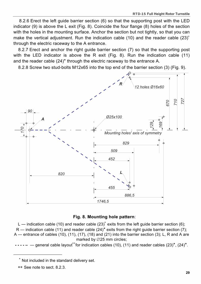
Fig. 8. Mounting hole pattern:
L — indication cable (10) and reader cable (23) exits from the left guide barrier section (6); R — indication cable (11) and reader cable (24)* exits from the right guide barrier section (7);
A — entrance of cables (10), (11), (17), (18) and (21) into the barrier section (3); L, R and А are marked by 25 mm circles;
- - - - – — general cable layoutfor indication cables (10), (11) and reader cables (23)*, (24)*.
Not included in the standard delivery set. Not included in the standard delivery set.
See note to sect. 8.2.3.
Assembly and operation manual
30
8.2.9 Lay the barrier section (3) down on the mounting surface so that the flange (4) is near the entrance А. Use a fish tape to drag the cables (10), (11), (17), (18) and (21) from the flange side throughout the supporting post out of the top end opening. Adjust lengths of the cable ends out of the top opening as follows:
– 0.8…1.0 m for the cables (10), (11), (17), (21); – 1.2…1.4 m for the cable (18).
Tape-scotch the ends to the top arm of the barrier section. 8.2.10 Erect the barrier section so that the flange (4) is on the A entrance, the bottom
rotation unit (5) is on the Ø25 mm hole (Fig. 8). Coincide the four flange holes and the hole in the center of the bottom rotation unit with holes in the mounting surface. Anchor the barrier section but not tightly, so that you can make the vertical adjustment.
8.2.11 Mount the ceiling plate (12) on top of the guide barrier sections (6) and (7) so that the two stud-bolts installed into the sections go through the plate while the plate wings, each with four edge counterbored holes, are above the sections. Make sure the thread bushings located on the sections enter the holes from below to secure tight fitting of the ceiling plate to the sections. Fix the ceiling plate on the top by eight screws М6х30, but not tightly.
8.2.12 Undo two screws М4х20 (15) with washers M4 that fix the cover (14) at each end of the top channel (13), lift and take off the cover.
8.2.13 Turn the top channel (13) so that the DIN-rail end (Fig.3) faces the barrier section (3), while the other end faces the guide barrier sections (6) and (7).
Use the stepladders to lift the top channel and lean it above the barrier section. Unfasten the cable ends off the top arm of the barrier section (sect. 8.2.9), put the ends into the top channel opening, tape-scotch the ends inside the top.
8.2.14 Fix the top channel atop placing it on the four stud-bolts: one end of the top channel on the two stud-bolts located on the barrier section (3) (sect. 8.2.8), another on two stud-bolts that stick out from the ceiling plate (12) (sect. 8.2.5).
Fix the barrier section end of the top channel: place the washer 12 on each stud-bolt, and then place the spring washer 12. Fix the top channel in place by two nuts М12 (Fig. 9), the nuts being screwed on to the middle of the stud-bolt protrusion.
Fix the ceiling plate end of the top channel: place two square washers** on the stud-bolts, then the plate**, then two spring washers 12 and fix the top channel in place with two nuts М12 (see Fig. 10). Screw all four nuts fixing the top channel, but not tightly.
8.2.15 Fix the ceiling plate with the top channel by four screws М6х30 from below: turn two of the screws into the top channel thread bushings, set another two screws inside the top channel and place on them two nuts М 6 with washers 6. Do not tighten the screws.
8.2.16 Fix the top channel to the top arm of the barrier section by two bolts М8х25 with washers 8. Do not tighten the bolts.
8.2.17 Install the walkway downlights into their holders (Fig. 3).
** The square washers and plate are placed inside the top channel (13) when delivered.
W A R N I N G ! Be extra cautious and careful when carrying out further work (sect. 8.2.13-8.2.14),
make sure the top channel does not fall before it is fixed in place
RTD-15 Full Height Rotor Turnstile
31
8.2.18 Lay the rotor section with fittings down on a flat horizontal surface. Attach one of the standard rotor sections and bolt down in the following sequence:
- install the reinforcing element on the top of the standard rotor section and fix the sections by 2 М8х50 bolts with spring washers 8 (Fig. 11А);
- use 10 М8х12 bolts with spring washers for complete fixing of the rotor sections. Likewise fix another rotor section (Fig. 11). Tighten the bolts. The rotor is assembled. 8.2.19 Check the position of the washer in the bottom rotation unit (5). The washer
should lie in the unit flatly, without warps and supported all the way by the bearing. 8.2.20 Lock both mechanical release locks located on the top channel (sect. 5.12). 8.2.21 Choose position of the rotor (ref. sect. 1.2). If the turnstile is meant to operate standalone (operation from the remote control panel),
either standard or Lock-chamber access modes can be chosen (Table 1, sections A and B). If the turnstile is integrated into an ACS (operation from an ACS controller),
we advise using only standard operating modes (Table 2). Choice between the standard or Lock-chamber mode is made by a respective
positioning of the barrier wings in the reset state (sect. 5.2.11). 8.2.22 Keeping a moderate slop, set the lower end of the assembled rotor (1)
(sect. 8.2.18) into the bottom rotation unit (5) in the reset state according to either A or B position of the barrier wings in the reset state (sect. 5.2.11).
To position the rotor for operation in the standard operating modes (the A reset state), close the passageway by one barrier wing placing it in parallel with the mounting holes’ axis of symmetry (Fig. 8) in the direction of the guide barrier sections (6) and (7) joint (Fig. 1 and 12а).
To position the rotor for operation in the Lock-chamber operating modes (the B reset state), close the passageway by two barrier wings in the direction of the supporting posts with LED indicators (6) and (7) (Fig. 4 and 12b).
Join the rotor shaft with the shaft of the operating mechanism by means of two half-couplings (16) with four bolts М8х30 with spring washers 8 (Fig. 13).
8.2.23 Check the rotor verticality with the level gauge. Eliminate vertical deviations, if necessary, by adjustment of the bottom rotation unit (5), the ceiling plate (12) and the top channel (13) as tolerated by the mounting holes. Tighten the bolts and screws fixing these parts.
8.2.24 Put Ø16 plugs into the boltholes connecting the rotor sections (1). 8.2.25 Open both mechanical release locks with keys (as given in sect. 5.12 key
override control) and try to revolve the rotor by hand. The rotation should be smooth and steady in both directions.
8.2.26 Tighten the anchor bolts of the flange (4) of the supporting post (3) and the flanges (8) of the guide barrier sections (6) and (7). Use joint liners to correct installation faults when necessary.
8.2.27 Recheck the rotor verticality with the level gauge. Verify free rotation of the barrier wings. Rotation force in the center of the barrier wing should not exceed 3 kgf (the conditional center of the barrier wing is in the middle of the fifth lowest barrier arm). The rotation force can be measured by a dynamometer or a household spring balance.
Note. When installing the RTD-15.2 turnstile, adjust its damper as per Adjustment Instruction (see Appendix C).
8.2.28 Close the turnstile with keys of the mechanical release locks (sect. 5.12). 8.2.29 Connect the cables (10), (11), (17) and (21) to the DIN-rail according to the
connection layout (Appendix А, Fig. А.1). Check installation of the «Fire Alarm» jumper;
Assembly and operation manual
32
install the «IMPULS» jumper when necessary (ref. sect. 5.5.3-5.5.4 and 5.11.3). 8.2.30 Connect the cable (18) to the walkway downlights according to the connection
layout (Appendix А, Fig. А.1). The installation is complete.
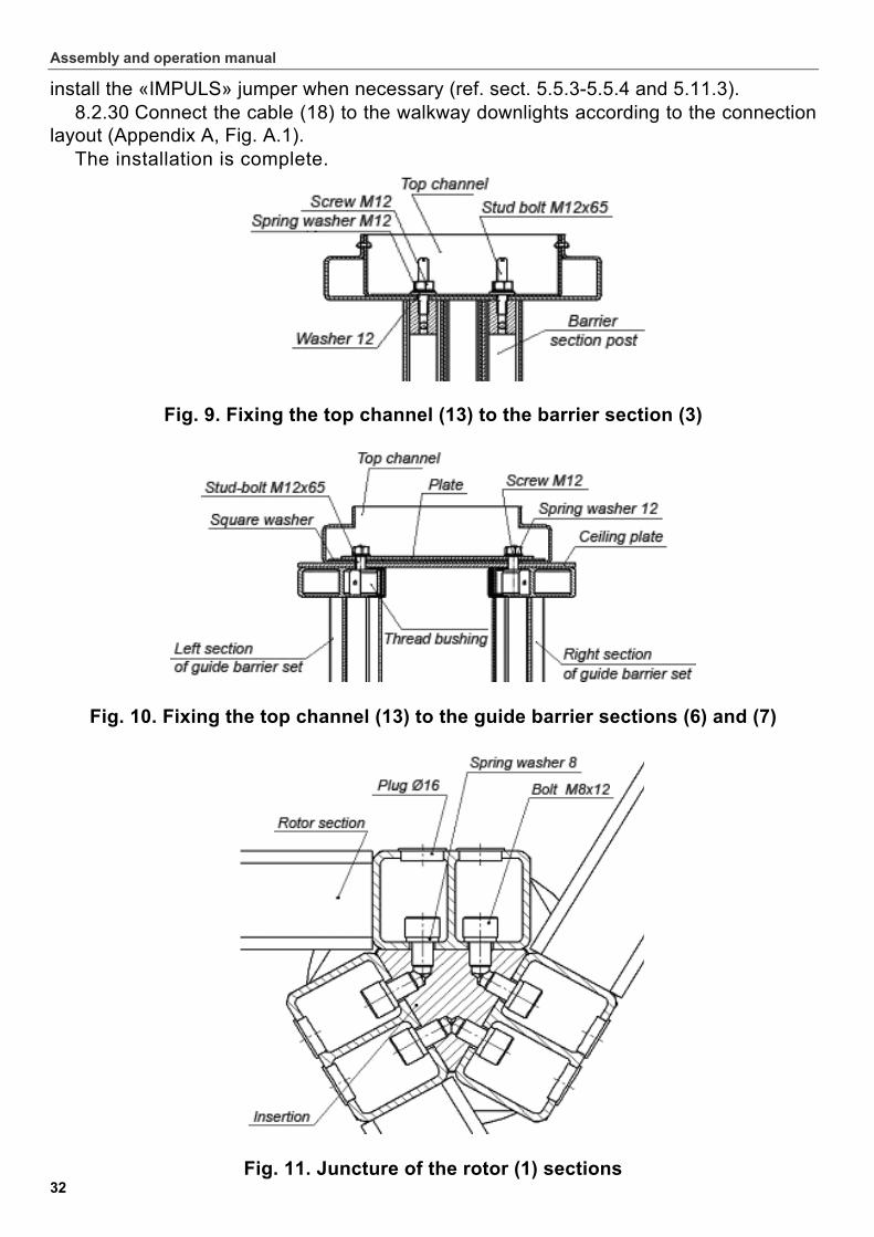
Fig. 9. Fixing the top channel (13) to the barrier section (3)
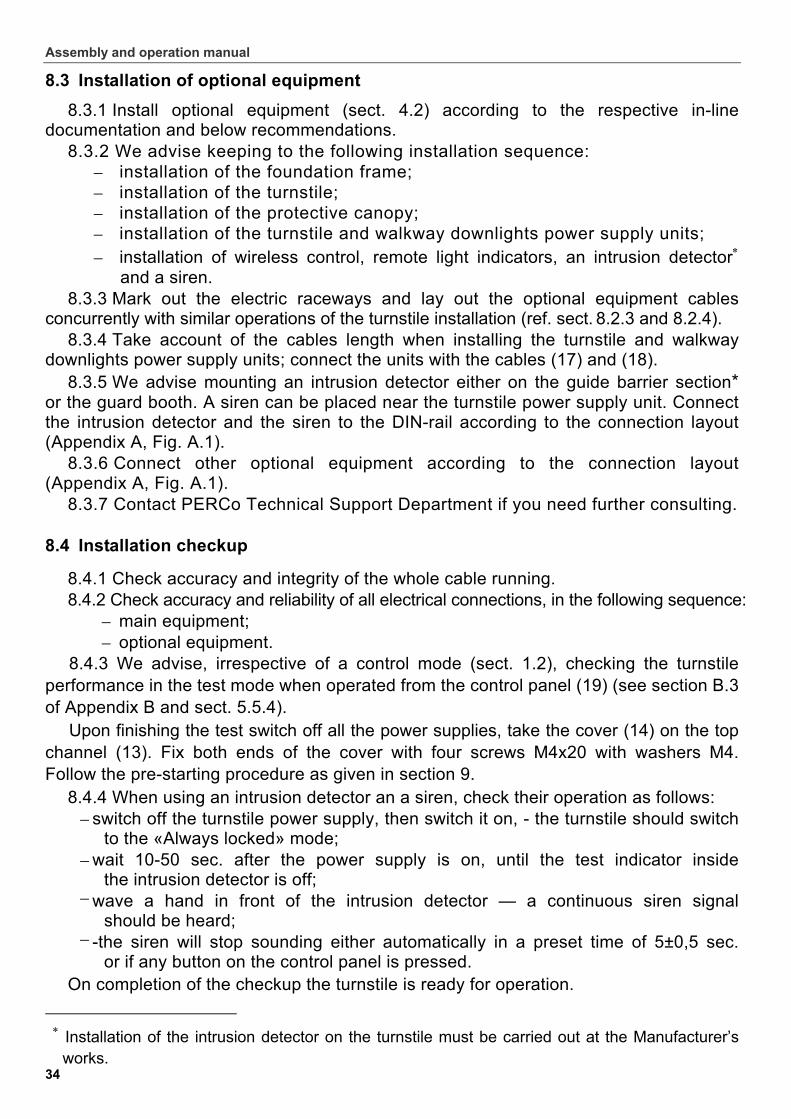
Fig. 10. Fixing the top channel (13) to the guide barrier sections (6) and (7)
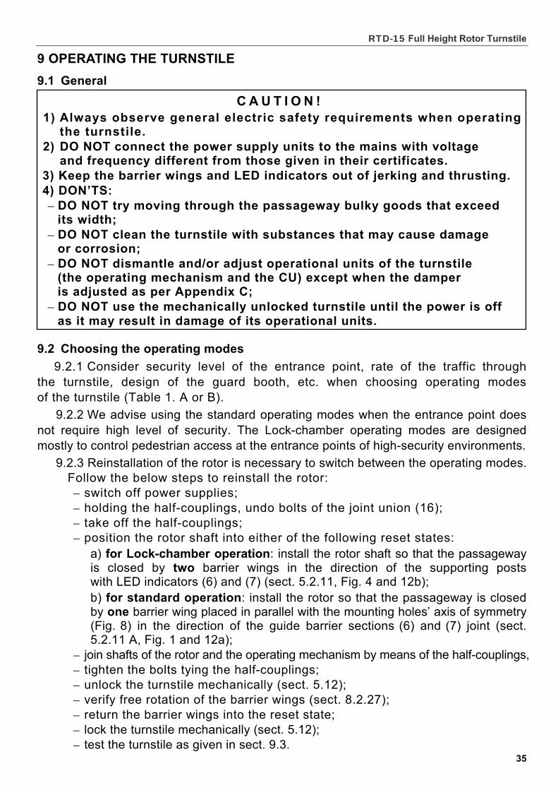
Fig. 11. Juncture of the rotor (1) sections

RTD-15 Full Height Rotor Turnstile
33
Fig.11А. Juncture of the rotor reinforcing elements
а) b)
Fig. 12. The barrier wings in the reset state (above view):
а). installed for standard operation; b). installed for Lock-chamber operation.
Рис. 13. Juncture of the operating mechanism shaft with the rotor (1) shaft by the union joint (16)
Assembly and operation manual
34
8.3 Installation of optional equipment
8.3.1 Install optional equipment (sect. 4.2) according to the respective in-line documentation and below recommendations.
8.3.2 We advise keeping to the following installation sequence: – installation of the foundation frame; – installation of the turnstile; – installation of the protective canopy; – installation of the turnstile and walkway downlights power supply units; – installation of wireless control, remote light indicators, an intrusion detector
and a siren. 8.3.3 Mark out the electric raceways and lay out the optional equipment cables
concurrently with similar operations of the turnstile installation (ref. sect. 8.2.3 and 8.2.4). 8.3.4 Take account of the cables length when installing the turnstile and walkway
downlights power supply units; connect the units with the cables (17) and (18). 8.3.5 We advise mounting an intrusion detector either on the guide barrier section*
or the guard booth. A siren can be placed near the turnstile power supply unit. Connect the intrusion detector and the siren to the DIN-rail according to the connection layout (Appendix А, Fig. А.1).
8.3.6 Connect other optional equipment according to the connection layout (Appendix А, Fig. А.1).
8.3.7 Contact PERCo Technical Support Department if you need further consulting.
8.4 Installation checkup
8.4.1 Check accuracy and integrity of the whole cable running. 8.4.2 Check accuracy and reliability of all electrical connections, in the following sequence:
– main equipment; – optional equipment.
8.4.3 We advise, irrespective of a control mode (sect. 1.2), checking the turnstile performance in the test mode when operated from the control panel (19) (see section B.3 of Appendix B and sect. 5.5.4).
Upon finishing the test switch off all the power supplies, take the cover (14) on the top channel (13). Fix both ends of the cover with four screws М4х20 with washers М4. Follow the pre-starting procedure as given in section 9.
8.4.4 When using an intrusion detector an a siren, check their operation as follows: – switch off the turnstile power supply, then switch it on, - the turnstile should switch
to the «Always locked» mode; – wait 10-50 sec. after the power supply is on, until the test indicator inside
the intrusion detector is off; – wave a hand in front of the intrusion detector — a continuous siren signal
should be heard; – -the siren will stop sounding either automatically in a preset time of 5±0,5 sec.
or if any button on the control panel is pressed.
On completion of the checkup the turnstile is ready for operation.
Installation of the intrusion detector on the turnstile must be carried out at the Manufacturer’s
works.
RTD-15 Full Height Rotor Turnstile
35
C A U T I O N ! 1) Always observe general electric safety requirements when operating
the turnstile. 2) DO NOT connect the power supply units to the mains with voltage
and frequency different from those given in their certificates. 3) Keep the barrier wings and LED indicators out of jerking and thrusting. 4) DON’TS: – DO NOT try moving through the passageway bulky goods that exceed
its width; – DO NOT clean the turnstile with substances that may cause damage
or corrosion; – DO NOT dismantle and/or adjust operational units of the turnstile
(the operating mechanism and the CU) except when the damper is adjusted as per Appendix C;
– DO NOT use the mechanically unlocked turnstile until the power is off as it may result in damage of its operational units.
9 OPERATING THE TURNSTILE
9.1 General
9.2 Choosing the operating modes
9.2.1 Consider security level of the entrance point, rate of the traffic through the turnstile, design of the guard booth, etc. when choosing operating modes of the turnstile (Table 1. A or B).
9.2.2 We advise using the standard operating modes when the entrance point does not require high level of security. The Lock-chamber operating modes are designed mostly to control pedestrian access at the entrance points of high-security environments.
9.2.3 Reinstallation of the rotor is necessary to switch between the operating modes. Follow the below steps to reinstall the rotor: – switch off power supplies; – holding the half-couplings, undo bolts of the joint union (16); – take off the half-couplings; – position the rotor shaft into either of the following reset states:
а) for Lock-chamber operation: install the rotor shaft so that the passageway is closed by two barrier wings in the direction of the supporting posts with LED indicators (6) and (7) (sect. 5.2.11, Fig. 4 and 12b); b) for standard operation: install the rotor so that the passageway is closed by one barrier wing placed in parallel with the mounting holes’ axis of symmetry (Fig. 8) in the direction of the guide barrier sections (6) and (7) joint (sect. 5.2.11 A, Fig. 1 and 12а);
– join shafts of the rotor and the operating mechanism by means of the half-couplings, – tighten the bolts tying the half-couplings; – unlock the turnstile mechanically (sect. 5.12); – verify free rotation of the barrier wings (sect. 8.2.27); – return the barrier wings into the reset state; – lock the turnstile mechanically (sect. 5.12); – test the turnstile as given in sect. 9.3.
Assembly and operation manual
36
9.3 Pre-starting procedure
9.3.1 Check the integrity and accuracy of all electrical connections.
9.3.2 Make sure the barrier wings are in the reset state, according to the chosen access mode (standard or Lock-chamber, see sect. 9.2).
9.3.3 Use the keys to check if the mechanical release locks are closed (the turnstile is locked mechanically, see sect. 5.12).
9.3.4 Connect power supply units of the turnstile and walkway downlights to the mains with voltage and frequency given in their respective specifications.
9.3.5 Switch on the power supply units. Both LED indicators (9) will show Red Cross. If the turnstile is connected to the control panel (19), the red light above the «STOP» will be on. Proper function of the turnstile will be confirmed by a single audio signal from the control panel. In 4 seconds after the power supply units are switched on, the turnstile switches to the «Always locked» mode. After that the turnstile is ready for operation.
9.3.6 Check performance of the turnstile in all operating modes as given in Tables 1 and 2, depending on the controlling device and function characteristics of the operating mechanism (sect. 5.2.9).
9.4 Troubleshooting
9.4.1Possible faults to be corrected by the customers themselves are listed in Table 7.
9.4.2 For faults not listed in Table 7 we advise to consult with PERCo Technical Support Department.
TABLE 7 TROUBLESHOOTING
FAULT MOST PROBABLE CAUSE REMEDY
Power supplies are on, but the turnstile does not function, the control panel lights and the LED indicators are off
Faulty connection or breakdown in the turnstile power supply cable (17)
Check connection the power supply cable (17)to the DIN-rail. Replace the cable if broken
The turnstile won’t open in the set direction, the control panel lights and the LED indicators are either off, or on but do not change their status
Faulty connection or breakdown in the control cable (21)
Check connection of the control cable (21) to the DIN-rail. Replace the cable if broken
No «PASS A» and «PASS B» signals to the ACS controller when the turnstile is open (the passage is not registered by the ACS)
Faulty connection, breakdown or short circuit in the control cable (21)
Check the «PASS A», «PASS В», «Common» connection circuits. Default, where necessary, faulty connection, breakdown or short circuit
More signals means a faulty detector, to be found as given in Table B.2, Appendix B (providing accomplishment of sect. 9.3.1-9.3.4).
RTD-15 Full Height Rotor Turnstile
37
10 MAINTENANCE
10.1 General
10.1.1 Regular maintenance works are necessary for proper performance and serviceability of the turnstile.
10.1.2 Maintenance works for the turnstile should be undertaken twice a year, or straight after a fault correction.
10.1.3 We advise to undertake maintenance works by at least two persons qualified in assembly and electric work, after thorough study of this Manual.
10.1.4 The maintenance works will include the following operations: partial dismantling of the turnstile, inside cleaning of the top channel, lubrication of subjected to wear parts of the operating mechanism and mechanical release locks, attachment reliability checkup for all parts and units, reinstallation of dismantled parts, adjustment of the damper (for the RTD-15.2 model) and general functional test.
Note. I. Adjustment of the principal units (the operating mechanism and the control unit),
is not a part of the maintenance works as these units are factory-adjusted and do not require any further adjusting.
II. Adjustment of the damper for the RTD-15.2 model is recommended when the turnstile is operating well beyond its operational temperature range (see Appendix C).
10.2 Maintenance works sequence
10.2.1 Undertake the maintenance work in the following sequence: – switch off and disconnect from the mains power supply units of the turnstile
and walkway downlights.;
– undo four screws М4х20 with washers М4 that fix the cover (14) at both ends of the top channel (13), lift and take off the cover;
– check and tighten when necessary all screw joints of the turnstile (sect. 8.2.11, 8.2.14-8.2.16 and Fig. 9 and 10);
– remove dirtying from inside the top channel; – assure the cables are secured safely; – lubricate with machine oil:
а) the stoppers and contact surfaces А of the operating mechanism — 2 or 3 oil drops into each lubrication point (shown in Fig. 14);
b) keyholes of the mechanical release locks; – make sure the mechanical release locks work smoothly and provide reliable
unlocking (free rotation) of the rotor in both directions (sect. 5.12); – return the cover in operative position and fix it with four screws М4х20
with washers M4; – holding the half-couplings, undo the bolts of the union joint (16) and remove
the half-couplings (Fig. 13); – lift gently and remove the rotor (1) from the bottom rotation unit (5);
keep a moderate slop and take the rotor out of the turnstile, lay it down a steady surface;
CAUTION! Be extra cautious and careful when taking off and reinstalling bulky or heavy parts (the top channel cover, half-couplings, rotor shaft, make sure the parts do not fall
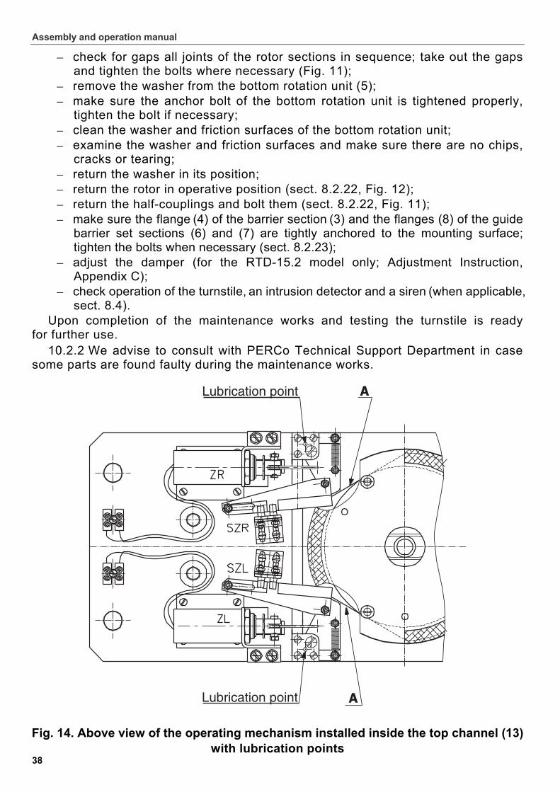
Assembly and operation manual
38
– check for gaps all joints of the rotor sections in sequence; take out the gaps and tighten the bolts where necessary (Fig. 11);
– remove the washer from the bottom rotation unit (5); – make sure the anchor bolt of the bottom rotation unit is tightened properly,
tighten the bolt if necessary; – clean the washer and friction surfaces of the bottom rotation unit; – examine the washer and friction surfaces and make sure there are no chips,
cracks or tearing; – return the washer in its position; – return the rotor in operative position (sect. 8.2.22, Fig. 12); – return the half-couplings and bolt them (sect. 8.2.22, Fig. 11); – make sure the flange (4) of the barrier section (3) and the flanges (8) of the guide
barrier set sections (6) and (7) are tightly anchored to the mounting surface; tighten the bolts when necessary (sect. 8.2.23);
– adjust the damper (for the RTD-15.2 model only; Adjustment Instruction, Appendix C);
– check operation of the turnstile, an intrusion detector and a siren (when applicable, sect. 8.4).
Upon completion of the maintenance works and testing the turnstile is ready for further use.
10.2.2 We advise to consult with PERCo Technical Support Department in case some parts are found faulty during the maintenance works.
Fig. 14. Above view of the operating mechanism installed inside the top channel (13) with lubrication points
RTD-15 Full Height Rotor Turnstile
39
11 TRANSPORTATION AND STORAGE
11.1 The turnstile in the original package should be transported in closed freight containers or other closed type cargo transport units.
11.2 During storage and transportation the boxes can be stacked no more than 2 layers high, taking into account their weight and safe load limits (Tables 4 and 5).
11.3 The turnstile should be stored indoors at ambient temperatures between -40°С to +55°С, and relative air humidity of up to 98% at + 25°С. The storage facilities should
be free from acid and alkali vapour and corrosive gases. 11.4 If prior to installation the turnstile was transported or stored at below-zero
temperatures or high air humidity, it should be kept in package for no less than 24 hours under operation conditions given in sect. 2.1-2.4).
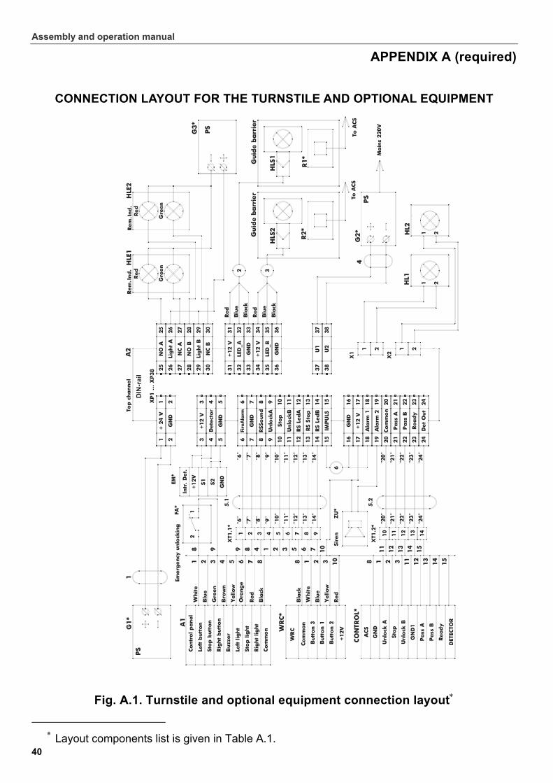
Assembly and operation manual
40
APPENDIX А (required)
CONNECTION LAYOUT FOR THE TURNSTILE AND OPTIONAL EQUIPMENT
Fig. А.1. Turnstile and optional equipment connection layout
Layout components list is given in Table А.1.
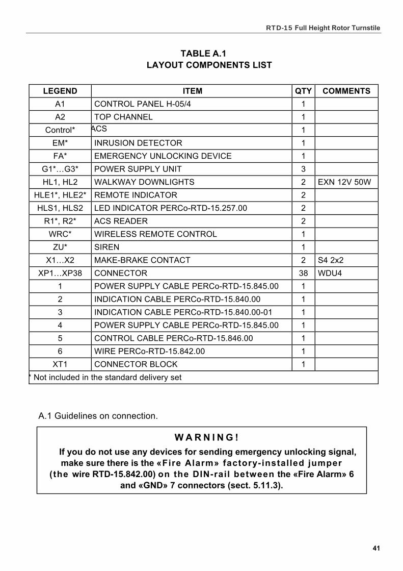
RTD-15 Full Height Rotor Turnstile
41
TABLE А.1
LAYOUT COMPONENTS LIST
LEGEND ITEM QTY COMMENTS
А1 CONTROL PANEL H-05/4 1
А2 TOP CHANNEL 1
Control* ACS 1
ЕМ* INRUSION DETECTOR 1
FА* EMERGENCY UNLOCKING DEVICE 1
G1*…G3* POWER SUPPLY UNIT 3
HL1, HL2 WALKWAY DOWNLIGHTS 2 EXN 12V 50W
HLE1*, HLE2* REMOTE INDICATOR 2
HLS1, HLS2 LED INDICATOR PERCо-RTD-15.257.00 2
R1*, R2* ACS READER 2
WRC* WIRELESS REMOTE CONTROL 1
ZU* SIREN 1
Х1…Х2 MAKE-BRAKE CONTACT 2 S4 2x2
ХР1…XP38 CONNECTOR 38 WDU4
1 POWER SUPPLY CABLE PERCо-RTD-15.845.00 1
2 INDICATION CABLE PERCо-RTD-15.840.00 1
3 INDICATION CABLE PERCо-RTD-15.840.00-01 1
4 POWER SUPPLY CABLE PERCо-RTD-15.845.00 1
5 CONTROL CABLE PERCо-RTD-15.846.00 1
6 WIRE PERCо-RTD-15.842.00 1
ХТ1 CONNECTOR BLOCK 1
* Not included in the standard delivery set
А.1 Guidelines on connection.
W A R N I N G !
If you do not use any devices for sending emergency unlocking signal, make sure there is the «Fire Alarm» factory-installed jumper
(the wire RTD-15.842.00) on the DIN-rail between the «Fire Alarm» 6 and «GND» 7 connectors (sect. 5.11.3).
Assembly and operation manual
42
APPENDIX B (recommended)
ALGORITHM OF CONTROL SIGNALS GENERATION FUNCTIONAL TEST SEQUENCE IN THE TEST MODE
B.1 Algorithm of control signals generation at the pulse control mode
By feeding a low-level signal relative to the «GND» contact to the DIN-rail contacts
«Unlock A», «Stop» and «Unlock B», the following commands can be generated
(sect. B.1.1-B.1.7).
B.1.1 «Always locked» (the turnstile is closed for entry and exit) — the active front at the «Stop» and a high-level signal at the «Unlock A» and «Unlock B» contacts.
Both directions are closed by this command.
B.1.2 «Single passage in direction А» (the turnstile is open for a single passage of one person in direction A) — the active front at the «Unlock A» contact and a high-level signal at the «Stop» and «Unlock B» contacts. This command opens direction A either for 5 seconds, or until completion of the passage, or until the «Always locked» command is given, whereas status of direction B will not change. The command is ignored if it is received at the moment when direction A is in the «Always free» mode.
B.1.3 «Single passage in direction B» (the turnstile is open for a single passage of one person in direction В) — the active front at the «Unlock B» contact and a high-level signal at the «Stop» and «Unlock A» contacts. This command opens direction B either for 5 seconds, or until completion of the passage, or until the «Always locked» command is given, whereas status of direction A will not change. The command is ignored if it is received at the moment when direction B is in the «Always free» mode.
B.1.4 «Bidirectional single passage» (the turnstile is open for a single passage of one person in each direction) — the active front at the «Unlock A» contact opens direction A with a high-level signal at the «Stop» contact, and the active front at the «Unlock B» contact opens direction B with a high-level signal at the «Stop» contact, sequence order of the fronts being of no difference. This command opens both directions, each for either 5 seconds, or until completion of the respective passage, or until the «Always locked» command is received. The command is ignored for either direction if it is received when this direction is in the «Always free» mode.
B.1.5 «Free passage in direction A» (the turnstile is open for multiple passage in direction A) — an active front at the «Unlock A» contact, a low-level signal at the «Stop» and a high-level signal at the «Unlock B» contact, or the active front at the «Stop» contact, a low-level signal at the «Unlock A» contact and a high-level signal at the «Unlock B» contact. This command opens direction A until the «Always locked» command is received, whereas status of direction B will not change.
The command is an active signal front (the signal level changes from high to low)
at a respective contact, relative to signal levels at other contacts. If the «Free passage in direction A» is received when direction B is open, the time interval
between the fronts of the signals «Stop» and «Unlock A» should not be more than 30 мs (i.e. simultaneous push of the buttons). Otherwise, the command can be interpreted as «Always locked», and direction B closed. The vice versa scenario for the «Free passage in direction B» applies.
RTD-15 Full Height Rotor Turnstile
43
B.1.6 «Free passage in direction В» (the turnstile is open for multiple passage in direction B) — the active front at the «Unlock B» contact, a low-level signal at the «Stop» contact and high-level contact at the «Unlock A» contact, or the active front at the contact «Stop», a low-level signal at the «Unlock B» contact and a high-level signal at the «Unlock A». This command opens direction B until the «Always locked» command is received, whereas status of direction A will not change .
B.1.7 «Always free» (the turnstile is open for multiple passages in both directions) — the active front at the «Unlock A» contact with a low-level signal at the «Stop» contact and the active front at the «Unlock B» contact with a low-level signal at the «Stop» contact, or the active front at the «Stop» contact with a low-level signal at the «Unlock A» and «Unlock B» contacts, sequence order of the fronts being of no difference. This command opens both directions until the «Always locked» command is received.
Note. For the remote control panel:
Active front — the moment of pushing a respective button on the control panel;
Low level — the respective button on the control panel is pushed;
High level — the respective button on the control panel is not pushed.
B.2 Algorithm of control signals generation at the potential control mode
B.2.1 «Both directions closed» (the turnstile is locked for entry and exit) — a high-level signal at the «Unlock A», «Unlock B» contacts or a low-level signal at the «Stop» contact. This command closes both directions.
B.2.2 «Direction A open» (the turnstile is open for passage in direction A) — a low-level signal at the «Unlock A» contact and a high-level signal at the «Stop», «Unlock B» contacts. This command opens direction A until a low-level signal is removed from the «Unlock A» contact, or the «Both directions closed» command is received, whereas status of direction B will not change.
B.2.3 «Direction B open» (the turnstile is open for passage in direction B) — a low-level signal at the «Unlock В» contact and a high-level at the «Stop», «Unlock А» contacts. This command opens direction B until a low-level signal is removed from the «Unlock B» contact, or the «Both directions closed» command is received, whereas status of direction A will not change.
B.2.4 «Both directions open» (the turnstile is open in for passage both directions) — a low-level signal at the «Unlock A» and «Unlock B» contacts and a high-level signal at the «Stop» signal. This command opens both directions until a low-level signal is removed from either «Unlock А» or «Unlock B» contact, or the «Both directions closed» command is received.
Note. For ACS controller outputs:
Low level — output relay contacts are closed, or the output transistor is open;
High level —output relay contacts are open, or the output transistor is closed.
Assembly and operation manual
44
B.3 Functional test sequence in the test mode
The test should be undertaken in the pulse control mode, from the remote control panel Н-05/4 (see sect. 5.5.4 and 5.7.1).
B.3.1 Power up the turnstile. After a single audio signal switch the turnstile into the test mode by a brief simultaneous push of all the three buttons on the control panel. The control panel indication is as given in sect. 1 of Table B.1.
The control panel will sound a single audio signal and, after turning to the test mode, the control panel indication will be as given in sect. 2 of Table B.1. Consumption current of the turnstile should not exceed 300 мА.
B.3.2 Set the rotor in the home position. Press the left button («L» button) on the control panel, observing that the L stopper is drawn back. The turnstile is open for the left passage; the control panel indication is as given in sect. 3 of Table B.1, while the CU microcontroller will check compliance of signals from the sensors of the L stopper. If the control panel buzzer does not sound over 10 seconds, the sensors are operational. If there are sounds from the buzzer, a faulty locking device sensor can be traced with the help of Table B.2.
B.3.3 Revolve the rotor into the unlocked direction 15°, whereupon the rotor will take the next position, and the buzzer will sound an audio signal as given in Table B.3. Revolving the rotor 360°, make certain that the number of audio signals correlates with the rotor position by Table B.3. Press the «STOP» button on the control panel.
B.3.4 Repeat the above testing, sect. B.3.2-B.3.3, for R direction, pushing the right button («R» button). The control panel indication should be as given in sect. 4
of Table B.1, the audio indication as in Table B.3.
B.3.5 Sequence of further testing depends on the model at hand, and given in sect. B.3.6 and B.3.7.
B.3.6 Functional test sequence for the RTD-15.1.
Push simultaneously the «STOP» and «L» buttons on the control panel, observing that both stoppers are drawn back. While the rotor should start a steady rotation in L direction, observe the following:
– the control panel indication should be as given in sect. 5 of Table B.1;
– signal change at the «PASS А(В)» outputs should correspond with a current position of the rotor;
– the rotor should rotate in the set direction;
– the rotor should rotate smoothly and steady.
Note. A continuous buzz signal from the control panel and the «Ready» signal represent that there is no change of signal from the optical rotation sensors within 10 seconds, which in turn warns of a fault in the circuits of the optical rotation sensors.
Repeat the above sequence for R direction. The control panel indication should be given as in sect. 6 of Table B.1.
RTD-15 Full Height Rotor Turnstile
45
B.3.7 Functional test sequence for the RTD-15.2.
Press simultaneously the «STOP» and «L» buttons on the control panel, observing that both stoppers are drawn back.
Revolve the rotor more than 50° into L direction, observing the following:
– the control panel indication should be as given sect. 5 of Table B.1;
– signal change at the «PASS А(В)» outputs should correspond with a current position of the rotor;
– the rotor should complete the rotation until set in the home position.
Note. A continuous buzz signal from the control panel and the «Ready» signal represent that there is no change of signal from the optical rotation sensors within 10 sec., which in turn warns of a fault in the circuits of the optical rotation sensors.
Repeat the above sequence for R direction. The control panel indication should be given as in sect. 6 of Table B.1.
B.3.8 Press the «STOP» button on the control panel upon completion of testing as given in either B.3.6 or B.3.7.
B.3.9 Leave the test mode by a brief simultaneous push of all the three control panel buttons. The control panel indication should be as given in sect. 7 of Table B.1.
In 10 seconds the control unit will switch into the normal operation, and the rotor will complete the rotation until set in the home position.
B.3.10 Make functional test of the «Fire Alarm» emergency unblocking by disconnecting the contacts 6 and on the 7 DIN-rail. The control panel indication should be as given in sect. 8 of Table B.1, the turnstile open in both directions.
Functional test in the test mode is complete.
We advise to contact PERCo Technical Support Department in the event of any malfunction during the testing.
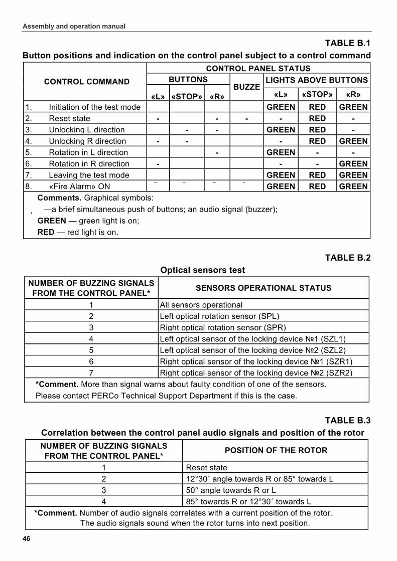
Assembly and operation manual
46
TABLE B.1
Button positions and indication on the control panel subject to a control command
CONTROL PANEL STATUS BUTTONS LIGHTS ABOVE BUTTONSCONTROL COMMAND
«L» «STOP» «R» BUZZE
«L» «STOP» «R»
1. Initiation of the test mode � � � � GREEN RED GREEN
2. Reset state - � - - - RED -
3. Unlocking L direction � - - � GREEN RED -
4. Unlocking R direction - - � � - RED GREEN
5. Rotation in L direction � � - � GREEN - -
6. Rotation in R direction - � � � - - GREEN
7. Leaving the test mode � � � � GREEN RED GREEN
8. «Fire Alarm» ON GREEN RED GREEN
Comments. Graphical symbols:
� —a brief simultaneous push of buttons; an audio signal (buzzer);
GREEN — green light is on;
RED — red light is on.
TABLE B.2
Optical sensors test
NUMBER OF BUZZING SIGNALS FROM THE CONTROL PANEL*
SENSORS OPERATIONAL STATUS
1 All sensors operational
2 Left optical rotation sensor (SPL)
3 Right optical rotation sensor (SPR)
4 Left optical sensor of the locking device №1 (SZL1)
5 Left optical sensor of the locking device №2 (SZL2)
6 Right optical sensor of the locking device №1 (SZR1)
7 Right optical sensor of the locking device №2 (SZR2)
*Comment. More than signal warns about faulty condition of one of the sensors.
Please contact PERCo Technical Support Department if this is the case.
TABLE B.3
Correlation between the control panel audio signals and position of the rotor
NUMBER OF BUZZING SIGNALS FROM THE CONTROL PANEL*
POSITION OF THE ROTOR
1 Reset state
2 12°30´ angle towards R or 85° towards L
3 50° angle towards R or L
4 85° towards R or 12°30´ towards L
*Comment. Number of audio signals correlates with a current position of the rotor. The audio signals sound when the rotor turns into next position.
RTD-15 Full Height Rotor Turnstile
47
APPENDIX C (required)
ADJUSTMENT INSTRUCTION FOR THE DAMPING DEVICE OF THE RTD-15.2 TURNSTILE
C.1 General notes
C.1.1 The damping device (the damper) is a part of the operating mechanism of the RTD-15.2 model with electromechanical drive and designated to provide smooth and shock-free stop of the rotor at the end of its automatic reset in the direction of the rotation until the barrier wings are in the home position.
C.1.2 Adjustment schedule:
- initial adjustment during the installation works before service (sect. 8.2.27);
- regular adjustment during the maintenance works (sect. 10).
Adjustment of the damper should also be carried out at significant changes of operational temperatures, e.g. seasonal temperature changes for turnstiles operating outdoors.
C.1.3 The damper should be tested and adjusted in the same environmental conditions as of the intended service of the turnstile.
C.2 Adjustment sequence
C.2.1 Proceed as follows before commencing adjustment of the damper:
– turn the turnstile power supply off;
– mechanically unlock the turnstile (sect. 5.12.2);
– check whether the barrier wings are not blocked and slowly turn the rotor manually over 60° in any direction from the home position until it starts resetting automatically;
– let the barrier wing go and the rotor finish the automatic reset;
– during the resetting, take notice how the rotor moves and stops:
a) the damper is properly adjusted if the rotation speed is similar to an average speed of comfortable passage through the turnstile and at the end of the resetting the rotor nears the home position at a gradually lower pace, making no return motion or noticeable swaying;
b) if the rotor nears the home position at a considerable speed, not stopping but “missing” it, then returns and sways around the home position, this means that the dampening effect should be increased;
c) if the rotor turns with a visible excessive slowdown, this means that the dampening effect should be decreased.
C A U T I O N !
The damper's maladjustment may result in breakage of other parts of the turnstile.
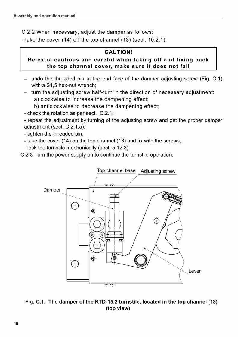
Assembly and operation manual
48
C.2.2 When necessary, adjust the damper as follows:
- take the cover (14) off the top channel (13) (sect. 10.2.1);
– undo the threaded pin at the end face of the damper adjusting screw (Fig. C.1) with a S1,5 hex-nut wrench;
– turn the adjusting screw half-turn in the direction of necessary adjustment: a) clockwise to increase the dampening effect; b) anticlockwise to decrease the dampening effect;
- check the rotation as per sect. С.2.1; - repeat the adjustment by turning of the adjusting screw and get the proper damper adjustment (sect. С.2.1,a); - tighten the threaded pin; - take the cover (14) on the top channel (13) and fix with the screws; - lock the turnstile mechanically (sect. 5.12.3).
C.2.3 Turn the power supply on to continue the turnstile operation.
Fig. C.1. The damper of the RTD-15.2 turnstile, located in the top channel (13) (top view)
CAUTION! Be extra cautious and careful when taking off and fixing back
the top channel cover, make sure it does not fall


PERCO
Postal address: P.O. Box 87, St. Petersburg, 194295
Russia
Technical support:
Tel: +7 812 3298924,+7 812 3298925 Fax: +7 812 2923608
e-mail: [email protected]
www.percoweb.com

www.perco.ru
www.percoweb.com