Embed Size (px)
Citation preview
Owner’s Manual Manuel de l’utilisateur Bedienungsanleitung Manual de Instrucciones Gebruiksaanwijzing Manuale di istruzioni Instruktionsbok àÌÒÚÛ͈Ëfl ÔÓθÁÓ‚‡ÚÂÎfl
RSP-1572Surround Sound Processor
Register your product at www.rotel.com/register
FL FR SL SR SblC SW Sbr
STANDBYSTANDBY
RSP-1572
GAIN
PARAMETRIC EQ
FREQ
DSP MUTESELMULTIINPUT ZONECD TUNER USB
VIDEO1 VIDEO2 VIDEO3 VIDEO4 VIDEO5 VIDEO6 2CHPL x
MODE
2 RSP-1572 SURROUND SOUND PROCESSOR
Connecting CD Player 23Connecting Audio Recorder 23Connecting AM/FM Tuner 23Connecting USB Audio/iPod/iPhone 23Zone Outputs (ZONE 2,3,4) 24
Operating the RSP-1572 . . . . . . . . . . . . . . . . . . . . . . . . . . . . . . . . . . . . . . . . . 24Front Panel Overview . . . . . . . . . . . . . . . . . . . . . . . . . . . . . . . . . . . . . . . . . . . 24
Front Panel Display 2 24Remote Sensor 2 24
Remote Control Overview . . . . . . . . . . . . . . . . . . . . . . . . . . . . . . . . . . . . . . . . 24Overview of Buttons and Controls . . . . . . . . . . . . . . . . . . . . . . . . . . . . . . . . . . . 25
STANDBY 1 and Power ON/OFF Buttons A 25VOLUME Knob and VOLUME +/- Buttons 6 C 25DISPLAY (DISP) Button D 25RCVR SETUP Button E 25Navigating and Select (ENT) keys F 25MUTE Button =B 25INPUT Buttons 378M 25ZONE Button 9 25SEL Button 0J 25MODE buttons - SUR+ J 25Playback buttons L 25RND Button I 25P-EQ Button/Knobs5D 25SPKR Button D 25MEM Button H 25Party Mode: Selecting the Same input for all outputs 90J 25
SURROUND SOUND . . . . . . . . . . . . . . . . . . . . . . . . . . . . . . . . . . . . . . . . . . . . . 26Overview of Surround Format . . . . . . . . . . . . . . . . . . . . . . . . . . . . . . . . . . . . . . 26
Dolby Surround & Dolby Pro Logic II 26Dolby Digital 26DTS 5.1 & DTS 96/24 26DTS Neo:6 27Dolby Digital Surround EX 27DTS-ES 6.1 and 7.1 Channel Surround 27Dolby Pro Logic IIx 6.1 and 7.1 Channel Surround 27Dolby Pro Logic IIz 7.1 Height Surround 27Rotel XS 6.1 and 7.1 Channel Surround 27Dolby Digital Plus 27Dolby True HD 27DTS-HD Master Audio & 27DTS-HD High Resolution Audio 27DSP Music Modes 272CH/5CH/7CH stereo formats 28Other Digital Formats 28
Automatic Surround Modes . . . . . . . . . . . . . . . . . . . . . . . . . . . . . . . . . . . . . . . . 29Manually Selecting Surround Modes . . . . . . . . . . . . . . . . . . . . . . . . . . . . . . . . . 29
Dolby Digital/TrueHD discs 30Dolby Digital Surround EX discs 30Dolby Digital 2.0 discs 30DTS/DTS-HD 5.1 discs 30DTS 96/24 discs 30DTS-ES 6.1 discs 30Digital Stereo discs 31Analog Stereo 31
BASIC OPERATIONS . . . . . . . . . . . . . . . . . . . . . . . . . . . . . . . . . . . . . . . . . . . . . 32Selecting Inputs . . . . . . . . . . . . . . . . . . . . . . . . . . . . . . . . . . . . . . . . . . . . . . . . 32Remote Zone Operation . . . . . . . . . . . . . . . . . . . . . . . . . . . . . . . . . . . . . . . . . . 32
Remote Zone Power On/Off 32Controlling Zones 2- 4 from the Main Room 33Controlling Zones 2 - 4 from Remote Locations 33
ContentsImportant Safety Instructions . . . . . . . . . . . . . . . . . . . . . . . . . . . . . . . . . . . . . . . 5
Figure 1: Control and Connections 6Figure 2: Remote Control 7Figure 3: Amplifier And Subwoofer 8Figure 4: Monitor, Video recording Connections 9Figure 5: DVD, Blu-ray Player and Cable, Satellite, HDTV tuner Connections 10Figure 6: DVD-A or SACD Player Connections 10Figure 7: Video Recorder Connections 11Figure 8: CD Player Connections 11Figure 9: Audio Recorder Connections 12Figure 10: AM/FM / Internet Radio Tuner Connections 12Figure 11: USB Audio /iPod Connections 13Figure 12: Zone Connection 14On-Screen Menus 15
About Rotel . . . . . . . . . . . . . . . . . . . . . . . . . . . . . . . . . . . . . . . . . . . . . . . . . . . 16Getting Started . . . . . . . . . . . . . . . . . . . . . . . . . . . . . . . . . . . . . . . . . . . . . . . . 16
Video Features 16Audio Features 16Surround Features 16Other features 17Unpacking 17Placement 17
Overview of Connections . . . . . . . . . . . . . . . . . . . . . . . . . . . . . . . . . . . . . . . . . 17Video Inputs and Outputs . . . . . . . . . . . . . . . . . . . . . . . . . . . . . . . . . . . . . . . . . 17
HDMI IN 1–6 Video Inputs i 18COMPOSITE IN 1–2 Video Inputs e 18COMPOSITE Video Output e 18COMPONENT VIDEO 1–2 18Video Inputs r 18COMPONENT Video output w 18High Definition TV Monitor Outputs ] 18HDMI Monitor Outputs ] 18
Audio Inputs and Outputs . . . . . . . . . . . . . . . . . . . . . . . . . . . . . . . . . . . . . . . . . 20Tuner Inputs d 20VIDEO 1–6 Audio Inputs g 20VIDEO Out Audio Output h 20CD Inputs f 20MULTI Inputs j 20Preamp Outputs k 20Digital Inputs t 20Digital Outputs y 20USB Audio Connection 4 20
Other Connections . . . . . . . . . . . . . . . . . . . . . . . . . . . . . . . . . . . . . . . . . . . . . . 21AC Input ; 21Master Power Switch a 2112V TRIGGER Connections o 21REM IN Jacks \ 21IR OUT Jacks [ 21Rear Mini USB Socket l 21Remote IR OUT p 21Computer I/O u 21
MAKING CONNECTIONS . . . . . . . . . . . . . . . . . . . . . . . . . . . . . . . . . . . . . . . . . . 22Connecting Amplifier 22Connecting a Subwoofer 22
Connecting Monitor . . . . . . . . . . . . . . . . . . . . . . . . . . . . . . . . . . . . . . . . . . . . . 22 ----HDTV Monitor/Video Recording 22Connecting DVD, Blu-ray Player and Cable, Satellite, HDTV tuner 22Connecting DVD-A or SACD Player 23Connecting Video Recorder 23
3English
USB/iPod operation . . . . . . . . . . . . . . . . . . . . . . . . . . . . . . . . . . . . . . . . . . . . . 33USB Storage Device Connection 4 33iPod/iPhone Connection 4 33PlayBack Control Buttons L 33
USB Bluetooth . . . . . . . . . . . . . . . . . . . . . . . . . . . . . . . . . . . . . . . . . . . . . . . . . 34USB Bluetooth dongle connection 34
SETUP . . . . . . . . . . . . . . . . . . . . . . . . . . . . . . . . . . . . . . . . . . . . . . . . . . . . . . . 34Menu Basics . . . . . . . . . . . . . . . . . . . . . . . . . . . . . . . . . . . . . . . . . . . . . . . . . . . 34
Navigation Buttons 34System Status 35Main Menu 35
Configuring Inputs . . . . . . . . . . . . . . . . . . . . . . . . . . . . . . . . . . . . . . . . . . . . . . 35Input Setup 35Multi Input Setup 37Dolby Pro Logic IIx 37DTS Neo:6 37
Configuring Speakers and Audio . . . . . . . . . . . . . . . . . . . . . . . . . . . . . . . . . . . . 38Speaker Setup 39Advanced Speaker Setup 39Subwoofer Setup 40Test Tone Setup 41Delay Setup 41
Miscellaneous Settings . . . . . . . . . . . . . . . . . . . . . . . . . . . . . . . . . . . . . . . . . . . 42Other Options 42Video/HDMI SETUP 42Zone 2-4 Setup 43Default Setup 43EQ Setup 44
Troubleshooting . . . . . . . . . . . . . . . . . . . . . . . . . . . . . . . . . . . . . . . . . . . . . . . . 45HDMI: Frequently Asked Questions . . . . . . . . . . . . . . . . . . . . . . . . . . . . . . . . . . 45
What is HDMI? 45What is the difference between HDMI and DVI? 45What is the difference between HDMI 1.4, HDMI 1.3 and earlier versions? 45Can I connect components which have earlier versions of HDMI? 46Which is the best way to rescale the picture? 46Will the HDMI digital output improve the picture quality from old analog sources? 46Why does the HDMI connection sometimes not give a picture? 46
Specifications . . . . . . . . . . . . . . . . . . . . . . . . . . . . . . . . . . . . . . . . . . . . . . . . . . 47
4 RSP-1572 SURROUND SOUND PROCESSOR
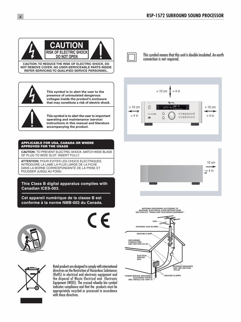
Rotel products are designed to comply with international directives on the Restriction of Hazardous Substances (RoHS) in electrical and electronic equipment and the disposal of Waste Electrical and Electronic Equipment (WEEE). The crossed wheelie bin symbol indicates compliance and that the products must be appropriately recycled or processed in accordance with these directives.
This symbol means that this unit is double insulated. An earth connection is not required.
DAB
FL FR SL SR SblC SW Sbr
STANDBYSTANDBY
RSP-1572
GAIN
PARAMETRIC EQ
FREQ
DSP MUTESELMULTIINPUT ZONECD TUNER USB
VIDEO1 VIDEO2 VIDEO3 VIDEO4 VIDEO5 VIDEO6 2CHPL x
MODE
5English
WARNING: There are no user serviceable parts inside. Refer all servicing to qualified service personnel.
WARNING: To reduce the risk of fire or electric shock, do not expose the unit to moisture or water. Do not expose the unit to dripping or splashing. Do not place objects filled with liquids, such as vases, on the unit. Do not allow foreign objects to get into the enclosure. If the unit is exposed to moisture, or a foreign object gets into the enclosure, immediately disconnect the power cord from the wall. Take the unit to a qualified service person for inspection and necessary repairs.
Read all the instructions before connecting or operating the component.
Keep this manual so you can refer to these safety instructions.
Heed all warnings and safety information in these instructions and on the product itself. Follow all operating instructions.
Clean the enclosure only with a dry cloth or a vacuum cleaner.
Do not use this unit near water.
You must allow a minimum 10 cm or 4 inches of unobstructed clearance around the unit .
Do not place the unit on a bed, sofa, rug, or similar surface that could block the ventilation openings. If the unit is placed in a bookcase or cabinet, there must be ventilation of the cabinet to allow proper cooling.
Keep the component away from radiators, heat registers, stoves, or any other appliance that produces heat.
WARNING: The rear panel power cord connector is the mains power disconnect device. The apparatus must be located in an open area that allows access to the cord connector.
The unit must be connected to a power supply only of the type and voltage specified on the rear panel. (USA: 120 V/60Hz, EC: 230V/50Hz)
Connect the component to the power outlet only with the supplied power supply cable or an exact equivalent. Do not modify the supplied cable. A polarized plug has two blades, with one wider than the other. A grounding plug has two blades plus a third grounding prong. These are provided for your safety. Do not defeat grounding and/or polarization safety provisions. If the supplied plug does not fit your outlet, please consult an electrician for replacement of the obsolete outlet. Do not use extension cords.
The main plug of the power cord set is a disconnect device of the apparatus. In order to completely disconnect the apparatus from the supply mains, the main plug of the power cord set should be unplugged from the mains (AC) outlet. The stand-by LED indicator will not be lit up to show the power cord is unplugged. The disconnect device shall remain readily operable.
Do not route the power cord where it will be crushed, pinched, bent, exposed to heat, or damaged in any way. Pay particular attention to the power cord at the plug and where the cord exits the back of the unit.
Main plug is used as the main disconnect device and shall remain ready accessible.
The power cord should be unplugged from the wall outlet during a lightning storm or if the unit is to be left unused for a long period of time.
Use only accessories specified by the manufacturer.
Use only with a cart, stand, rack, bracket or shelf system recommended by Rotel. Use caution when moving the unit in a stand or rack to avoid injury from a tip-over.
Immediately stop using the component and have it inspected and/or serviced by a qualified service agency if:• Thepowersupplycordorplughasbeendamaged• Objectshavefallenorliquidhasbeenspilledintotheunit• Theunithasbeenexposedtorain• Theunitshowssignsofimproperoperation• Theunithasbeendroppedordamagedinanyway
The batteries in remote control shall not be exposed to excessive heat such as sunshine, fire or the like.
WARNING: The master power switch is located on the rear panel. The unit must allow unobstructed access to the main power switch.
Important Safety InstructionsNoticeThe COMPUTER I/O connection should be handled by authorized persons only.
FCC InformationThis equipment has been tested and found to comply with the limits for a Class B digital device, pursuant to Part 15 of the FCC Rules. These limits are designed to provide reasonable protection against harmful interference in a residential installation. This equipment generates, uses and can radiate radio frequency energy and, if not installed and used in accordance with the instruction, may cause harmful interference to radio communications.
However, there is no guarantee that interference will not occur in a particular installation. If this equipment does cause harmful interference to radio or television reception, which can be determined by turning the equipment off and on, the user is encouraged to try to correct the interference by one or more of the following measures:
•Reorientorrelocatethereceivingantenna.(TV,radio,etc.)
•Increasetheseparationbetweentheequipmentandreceiver
•Connect theequipment toanoutletoncircuitdifferent fromthat towhich thereceiver isconnected.
•Consultthedealeroranexperiencedradio/TVtechnicianforadditionalhelp.
CautionThis device complies with part 15 of the FCC Rules. Operation is subject to the following to conditions: (1) This device may not cause harmful interference, and (2) this device must accept any interference received, including interference that may cause undesired operation.
NOTE TO CATV SYSTEM INSTALLER: Call the CATV system or antenna installer’s attention to Article 820-40 of the NEC. This provides guidelines for proper grounding and, in particular , specifies that the cable ground shall be connected to the grounding system of the building, as close to the point of cable entry as practical. See installation diagram.
NOTE: This equipment has been tested and found to comply with the limits for a Class B digital device, pursuant to Part 15 of the FCC Rules. These limits are designed to provide reasonable protection against interference in a residential installation. This equipment generates and can radiate radio frequency energy and, if not installed and used in accordance with the instructions, may cause interference to radio or TV communications. There is no guarantee that interference will not occur in a particular installation. If this equipment does cause interference to radio or television reception, which can be determined by turning the equipment off and on, try to correct the interference by one or more of the following measures:
•Reorientorrelocatethereceivingantenna.•Increasetheseparationbetweentheunitandthetelevisiontuner.•ConnecttheunittoanACpoweroutletonadifferentelectricalcircuit.•ConsultyourauthorizedRotelretailerforassistance.
6 RSP-1572 SURROUND SOUND PROCESSOR
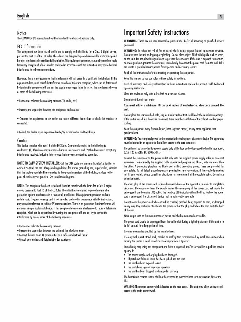
Figure 1: Control and Connections
ON
OFF
FL FR SL SR SblC SW Sbr
STANDBYSTANDBY
RSP-1572
GAIN
PARAMETRIC EQ
FREQ
DSP MUTESELMULTIINPUT ZONECD TUNER USB
VIDEO1 VIDEO2 VIDEO3 VIDEO4 VIDEO5 VIDEO6 2CHPL x
MODE
1 2 3 -
4 5 6 7 8 90 - =
q w e r t y u i o p [ ] \ a
s d f g h j k l ;
7English
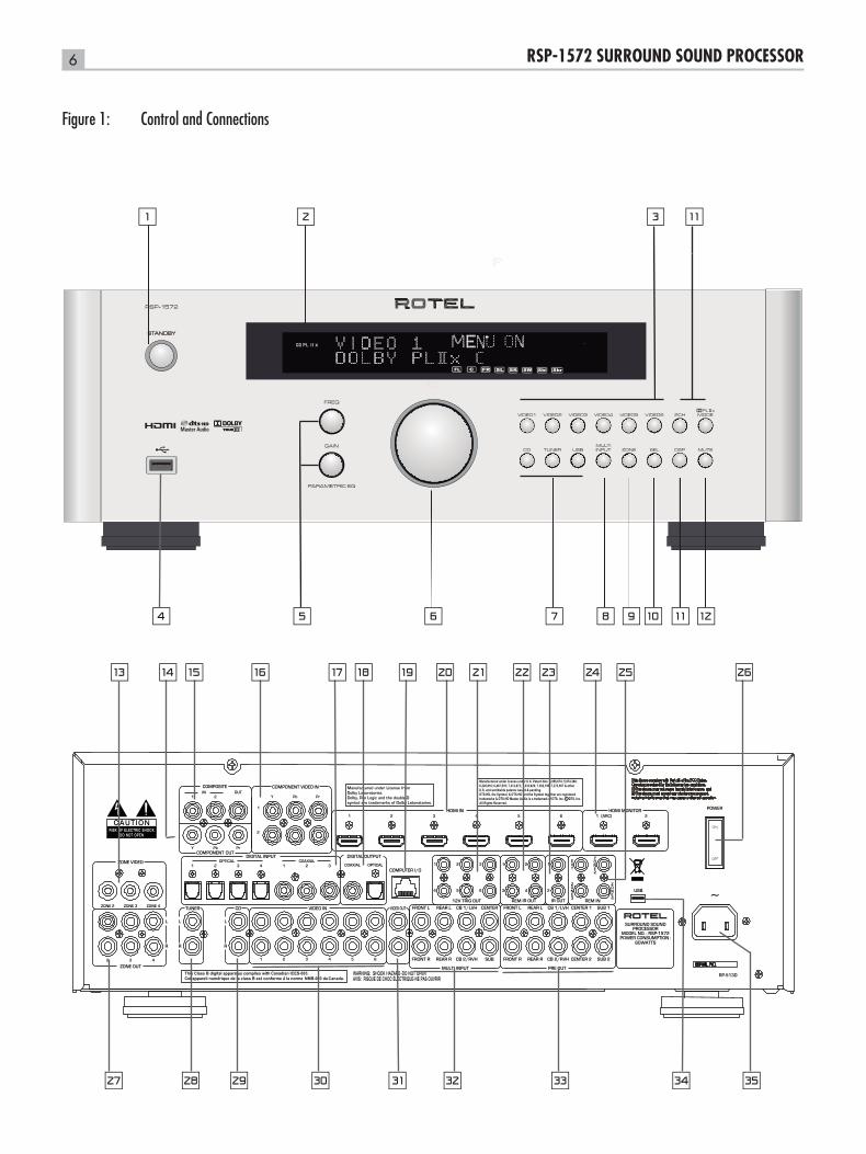
Figure 2: Remote Control
P-EQ SPKR
RCVR
SETUP
MENU
GUIDE EXIT
PLCM SUR+
P-TUN
CH+CH-
FRQ-D
USB
VID 1 VID 2 VID 3 PTY
VID 4 VID 5 VID 6 MULTI
CD TUN BAND
SUBT
SEL
AUDIO
ENT
10+
RR-CX94
ACDE
G
I
J
L
A
F
H
B
M
8 RSP-1572 SURROUND SOUND PROCESSOR
REAR LEFTAMPLIFIER
CB 2 /RVHCB 1 /LVH
REAR RIGHTAMPLIFIER
SUBWOOFERINPUT
FRONT LEFTAMPLIFIER
CENTREAMPLIFIER
FRONT RIGHTAMPLIFIER
ON
OFF
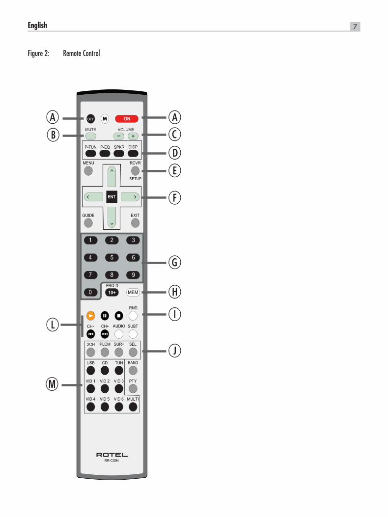
Figure 3: Amplifier And Subwoofer
9English
Figure 4: Monitor, Video recording Connections
ON
OFF
480p/576p/720p/1080i/1080p HDTV
S-VIDEO
COMPONET VIDEO
VIDEO INPUT
Y Pb Pr
COMPOSITEVIDEO
AUDIO OUTPUT
RIGHT LEFT
480i/576i TV
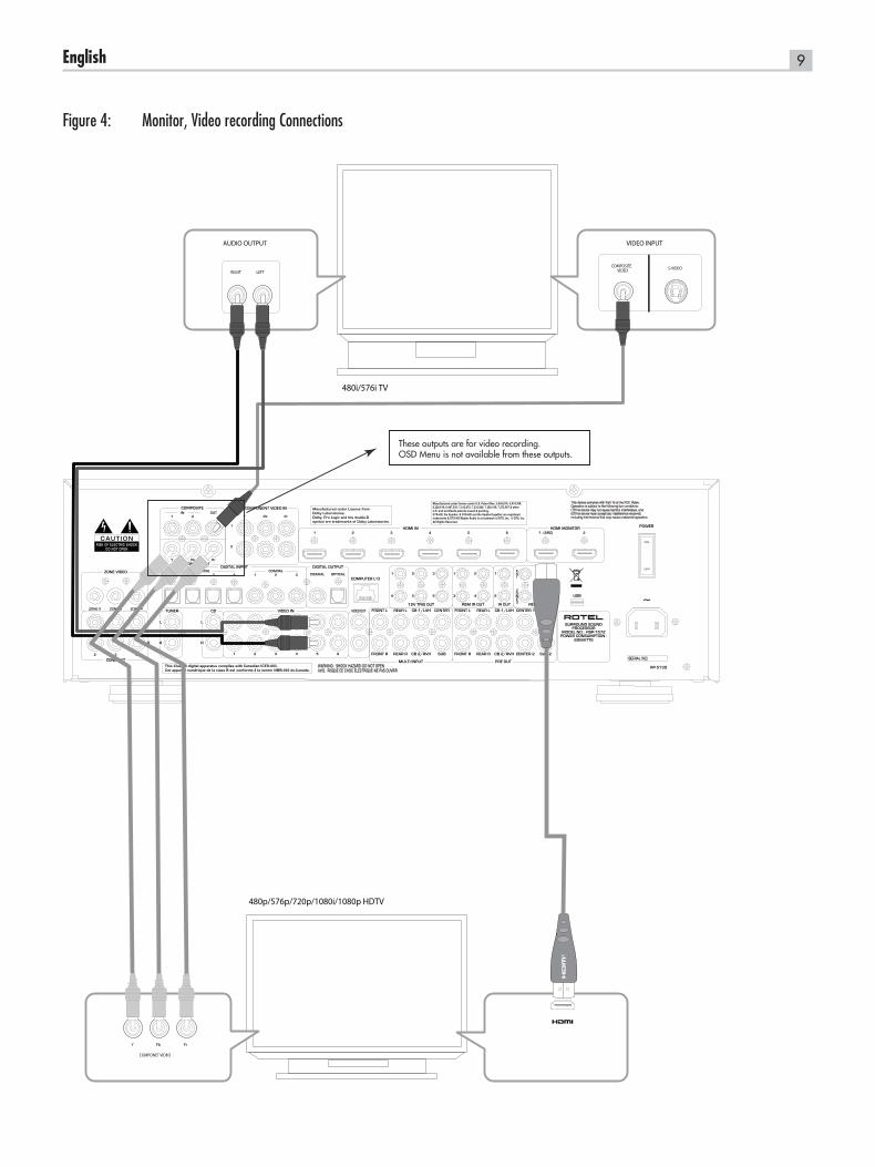
These outputs are for video recording.OSD Menu is not available from these outputs.
10 RSP-1572 SURROUND SOUND PROCESSOR
Figure 5: DVD, Blu-ray Player and Cable, Satellite, HDTV tuner Connections
Figure 6: DVD-A or SACD Player Connections
S-VIDEO
VIDEO OUTPUT
COMPOSITEVIDEO
AUDIO OUTPUT
RIGHT LEFT
ANALOGDIGITALY PrPb
COMPONET VIDEO
ON
OFF
MULTICHANNEL ANALOG OUTPUT
FRONT R SUBREAR R CENTRE FRONT LREAL L
ON
OFF
11English
Figure 7: Video Recorder Connections
S-VIDEO
VIDEO
COMPOSITE
LINE OUT REC IN
S-VIDEO COMPOSITE
AUDIO
RIGHT LEFT
LINE OUTRIGHT LEFT
REC IN
ON
OFF
Figure 8: CD Player Connections
AUDIO OUTPUT
RIGHT LEFT
DIGITAL ANALOG
ON
OFF
12 RSP-1572 SURROUND SOUND PROCESSOR
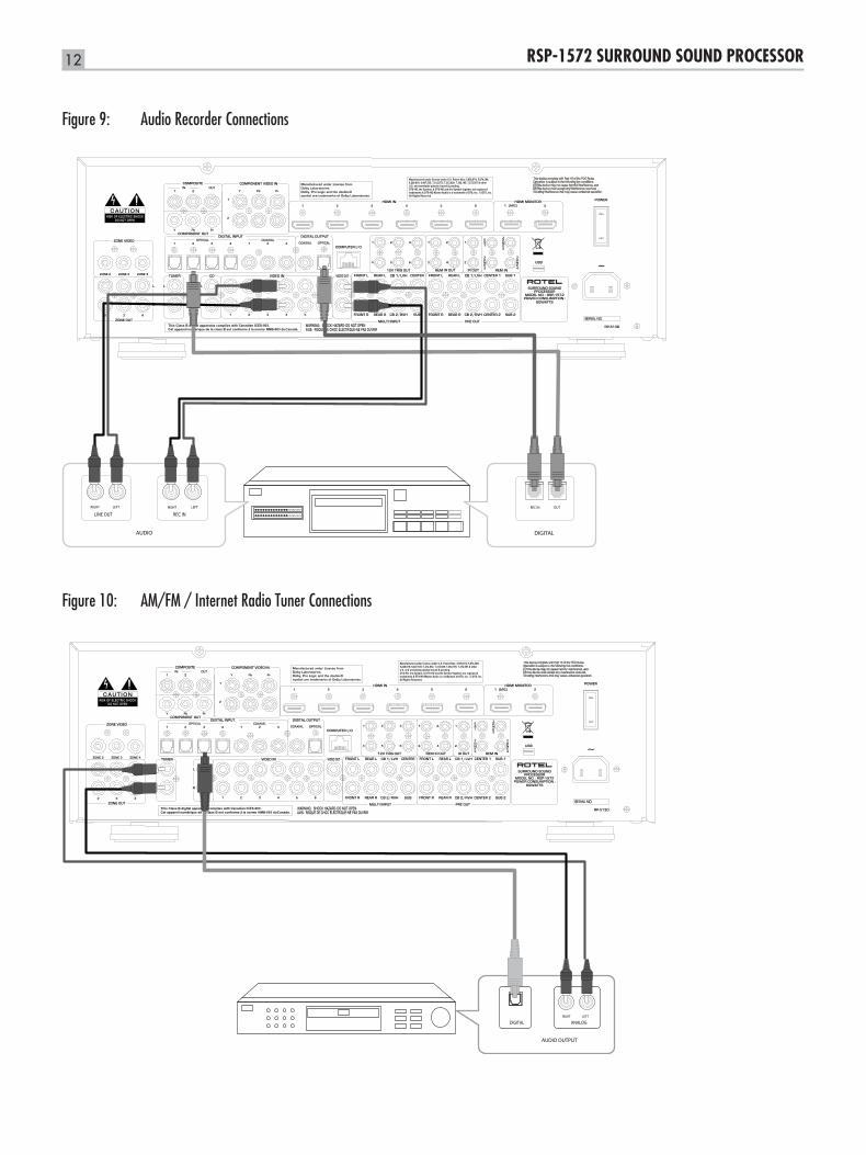
Figure 9: Audio Recorder Connections
ON
OFF
AUDIO
RIGHT LEFT
REC IN
RIGHT LEFT
LINE OUT
DIGITAL
REC IN OUT
Figure 10: AM/FM / Internet Radio Tuner Connections
ON
OFF
AUDIO OUTPUT
RIGHT LEFT
DIGITAL ANALOG
13English
US
B S
TIC
K
FL FR SL SR SblC SW Sbr
STANDBYSTANDBY
RSP-1572
GAIN
PARAMETRIC EQ
FREQ
DSP MUTESELMULTIINPUT ZONECD TUNER USB
VIDEO1 VIDEO2 VIDEO3 VIDEO4 VIDEO5 VIDEO6 2CHPL x
MODE
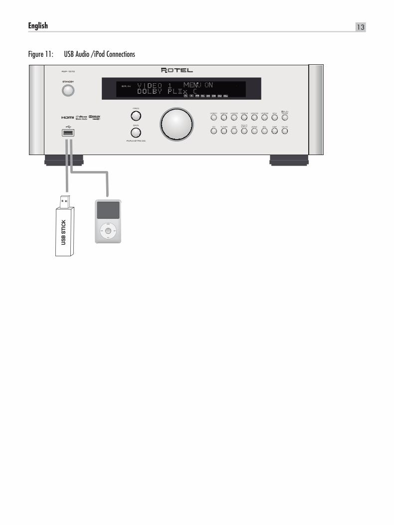
Figure 11: USB Audio /iPod Connections
14 RSP-1572 SURROUND SOUND PROCESSOR
ON
OFF
ZONE 2 IR
S-VIDEO
VIDEO INPUT
COMPOSITEVIDEO
480i/576i TV
LEFTCHANNEL
RIGHTCHANNEL
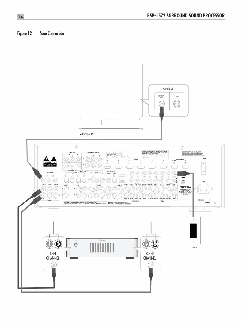
Figure 12: Zone Connection
15English
M A I N M E N U
I N P U T S P E A K E R
D E L A Y T E S T T O N E
S U B S E T U P Z O N
O T H E R V I D E O / H D M I
S T A T U S E Q
D E F A U L T
E X I T
E
I N P U T S E T U P
L I S T E N : C D
V I D E O I N P U T : O f f
I N P U T L A B E L : _ _ _ _ _ _ _ _
A U D I O I N P U T : C o a x i a l 2
I N P U T A T T . : 0 d B
C I N E M A E Q : O f f
1 2 V T R I G G E R : 1 _ _ _ _ 6
D E F A U L T M O D E : D o l b y P L I I x M u s
G R O U P D E L A Y : 2 0 0 m S
M A I N M E N U
S P E A K E R S E T U P
F R O N T : S m a l l
C E N T E R : S m a l l
S U R R O U N D : S m a l l
C E N T E R B A C K : _ _ _ _ _ _
F R O N T H E I G H T : S m a l l
S U B W O O F E R : Y e s
C - B A C K / F - H E I G H T : F R O N T H E I G H T
A D V A N C E D : E n t e r
M A I N M E N U
S Y S T E M S T A T U S
L I S T E N : T u n e r
V I D E O I N P U T : O f f
R E C O R D : S o u r c e
M O D E : D o l b y P L I I x M u s i c
A U D I O I N P U T : A n a l o g
V O L U M E : 4 5
S P E A K E R S : F L C N T S U B F R
S L C B 1 C B 2 S R
V i d e o 1 O f f V i d e o 5Z O N E 2 : Z O N E 3 : Z O N E 4 :
I N P U T S E T U P
L I S T E N : M u l t i I n p u t
V I D E O I N P U T : H D M I 1
I N P U T L A B E L : _ _ _ _ _ _ _ _
I N P U T A T T . : 0 d B
L F E R E D I R E C T : O n
1 2 V T R I G G E R : 1 2 _ _ _ _
M A I N M E N U
A D V S P E A K E R S E T U P
S P E A K E R : F r o n t
C R O S S O V E R : 1 0 0 H z
D O L B Y : S m a l l
D T S : S m a l l
S T E R E O : L a r g e
D S P : S m a l l
S P E A K E R S E T U P M E N U
T E S T T O N E
F L : + 1 d B F R : + 2 d B
C N T : - 1 d B S W: + 9 d B
S L : + 4 d B S R : + 5 d B
C B L : - - - - - C B R : - - - - -
L V H : - 3 d B R V H : + 3 d B
M A I N M E N U
I N P U T S E T U P
L I S T E N : V i d e o 1
V I D E O I N P U T : H D M I 1
I N P U T L A B E L : _ _ _ _ _ _ _ _
A U D I O I N P U T : H D M I A u d i o
I N P U T A T T . : 0 d B
C I N E M A E Q : O f f
1 2 V T R I G G E R : 1 _ _ _ _ 6
D E F A U L T M O D E : D o l b y P L I I x C i n
G R O U P D E L A Y : 0 m S
M A I N M E N U
S U B W O O F E R S E T U P
C R O S S O V E R : 1 0 0 H z
D o l b y D i g i t a l : 0 d B
D o l b y P L I I x : 0 d B
D T S : 0 d B
S T E R E O : 0 d B
D S P : 0 d B
M U L T I L P C M : 0 d B
M U L T I I N P U T : 0 d B
M A I N M E N U
Z O N E S E T U P
M A I N M E N U
Z O N E : Z O N E 2S O U R C E : C D
V I D E O I N P U T : C o m p o s i t e 1
V O L U M E S E T U P : V a r i a b l eV O L U M E : 6 0
T U R N O N V O L : L a s t M A X V O L : M a x
1 2 V T R I G G E R : 1 _ 3 _ _ _
D O L B Y P R O L O G I C I I x
M O D E : M u s i c
O P T I O N A L P A R A M E T E R S
P A N O R A M A : O f f
D I M E N T I O N : 3
C E N T E R W I D T H : 3
I N P U T S E T U P M E N U
O T H E R O P T I O N S
R E C O R D : S o u r c e
T U R N O N V O L : L a s t
M A X V O L : M a x
P O W E R : D i r e c t
L A N G U A G E : E N G L I S H
D I S C R E T E : N o
S / W U P G R A D E : E n t e r
M A I N M E N U
E Q O P T I O N S
E Q E N A B L E : O f f
S P E A K E R : A L L
E Q V A L U E : E n t e r
M A I N M E N U
D T S N e o : 6
M O D E : C i n e m a
I N P U T S E T U P M E N U
V I D E O / H D M I
A N A L O G V I D E O O U T : 4 8 0 p / 5 7 6 p
H D M I A U D I O M O D E : A M P M o d e
H D M I C O N T R O L : O n
M A I N M E N U
P O W E R C O N T R O L : N o
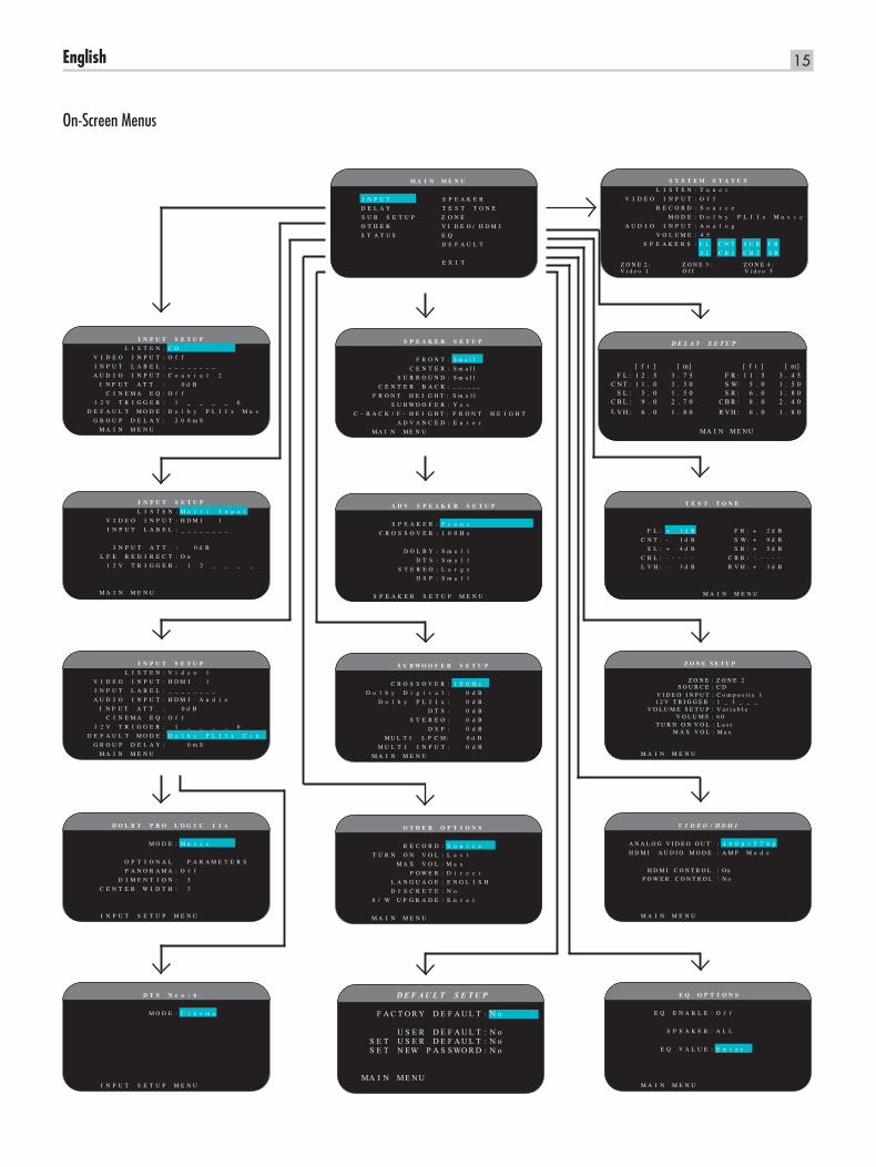
On-Screen Menus
D E F A U L T S E T U P
F A C T O R Y D E F A U L T : N o
U S E R D E F A U L T : N oS E T U S E R D E F A U L T : N oS E T N EW P A S S WO R D : N o
MA I N ME N U
D E L A Y S E T U P
[ f t ] [ m] [ f t ] [ m]F L : 1 2 . 5 3 . 7 5 F R : 1 1 . 5 3 . 4 5
C N T : 1 1 . 0 3 . 3 0 S W: 5 . 0 1 . 5 0S L : 5 . 0 1 . 5 0 S R : 6 . 0 1 . 8 0
C B L : 9 . 0 2 . 7 0 C B R : 8 . 0 2 . 4 0L V H : 6 . 0 1 . 8 0 R V H : 6 . 0 1 . 8 0
MA I N M E N U
16 RSP-1572 SURROUND SOUND PROCESSOR
About RotelOur story began 50 years ago. Over the decades, we have received hundreds of awards for our products and satisfied hundreds of thousands of people who take their entertainment seriously- like you!
Rotel was founded by a family whose passionate interest in music led them to manufacture high-fidelity components of uncompromising quality. Through the years, that passion has remained undiminished and the family goal of providing exceptional value for audiophiles and music lovers, regardless of their budget, is shared by all Rotel employees.
Rotel’s engineers work as a close team, listening to, and fine tuning, each new product until it reaches their exacting musical standards. They are free to choose components from around the world in order to make that product the best they can. You are likely to find capacitors from the United Kingdom and Germany, semiconductors from Japan or the United States, while toroidal power transformers are manufactured in Rotel’s own factory.
We all have concerns about our environment. And, as more and more electronics are produced and later discarded, it is especially important for a manufacturer to do all it can to engineer products that have a minimum negative impact on landfill sites and water tables.
At Rotel, we are proud to do our part. We have reduced the lead content in our electronics by using special RoHS solder, while our new Class D (not digital) amplifiers are up to five times more efficient than our legacy designs and still deliver power and performance. These products run cool, give minimum wasted energy, are good for the environment and give better sound too.
Finally, we have printed this brochure on recycled paper stock.
While we understand that these are small first steps, they are still important ones. And we continue to pursue new methods and materials for a cleaner and greener manufacturing process.
All of us at Rotel thank you for buying this product. We are sure it will bring you many years of enjoyment.
Manufactured under license from Dolby Laboratories. Dolby, Pro Logic and the double-D symbol are trademarks of Dolby Laboratories. Copyright 1995-2005. All rights reserved.
Manufactured under license under U.S. Patent #’s: 5,451,942; 5,956,674; 5,974,380; 5,978,762; 6,226,616; 6,487,535; 7,212,872; 7,333,929; 7,392,195; 7,272,567 & other U.S. and worldwide patents issued & pending. DTS, DTS-HD and the Symbol are registered trademarks, & DTS-HD Master Audio, and the DTS logos are trademarks of DTS, Inc. Product includes software. © DTS, Inc. All Rights Reserved.
This item incorporates copy protection technology that is protected by U.S. patents and other intellectual property rights of Rovi Corporation. Reverse engineering and disassembly are prohibited.
Getting StartedThank you for purchasing the Rotel RSP-1572 Surround Sound Processor .The unit is a full-featured audio/video control center for analog and digital source components. It features digital processing for a wide range of formats including Dolby Surround®, Dolby Digital® and DTS® source material.
Video FeaturesAnalog input and output video connections for use with Composite •video and Component Video signals, including conversion to HDMI Video output.
HDMI switching for digital video signals up to 1080p, and HDMI •Bypass video. Compatible with DVI components with HDMI-DVI adapter. For more information see the section ‘HDMI: Frequently Asked Questions’ in this manual.
Videophile line-doubling and scaling up to high-definition •resolutions.
Accepts any type of video input: NTSC 480i, PAL 576i, NTSC 480p, •PAL 576p, 720p, 1080i, 1080p, 1080p 24Hz and 1080p 3D.
Outputs digital or analog video at any resolution (NTSC 480i, PAL •576i, NTSC 480p, PAL 576p, 720p, 1080i, 1080p,1080p 3D) to match any digital or analog TVs.
Audio FeaturesRotel’s Balanced Design Concept combines advanced circuit board •layout, comprehensive parts evaluation, and extensive listening tests for superior sound and reliability.
Analog bypass mode for pure 2-speaker stereo with no digital •processing.
Optical digital, coax digital, and analog input and output audio •connections. (HDMI video connections also carry digital audio, so when using HDMI there is no need for separate audio cables.)
DVD-A high-resolution multichannel audio signals are automatically •detected.
MULTI Input for 7.1 channel analog signals from DVD-A and SACD •players. Subwoofer options include .1 channel pass through or bass redirect feature with an analog low-pass filter for a summed subwoofer output from seven channels.
Surround FeaturesAutomatic Dolby® Digital decoding for Dolby® Digital 2.0, Dolby® •Digital 5.1, Dolby® Digital Surround EX™, Dolby® TrueHD and Dolby® Digital Plus recordings.
Dolby® Pro Logic® IIx and Dolby® Pro Logic® IIz decoding (for 6.1 •and 7.1 channel systems) with improved separation and frequency response for Dolby® Surround matrix encoded recordings. Can be optimized for Music or Cinema sources, Pro Logic® or Games.
Automatic decoding for DTS® 5.1 channel, DTS-ES® Matrix 6.1 •channel, DTS-ES® Discrete 6.1 channel, DTS 96/24, DTS-ES®
17English
96/24 digital, DTS-HD™ Master Audio and DTS-HD™ High Resolution recordings
DTS® Neo:6® Surround modes for deriving surround channels for 5.1, •6.1 or 7.1 channel systems from 2-channel stereo or matrix surround recordings. Can be optimized for Music or Cinema sources.
Rotel XS (eXtra Surround) automatically ensures proper decoding and •optimum performance from any multichannel digital signal on 6.1 and 7.1 channel systems. Always active in any system with center back speaker(s), Rotel XS even works with signals that would not otherwise activate the proper decoding (such as non-flagged DTS-ES and Dolby Surround EX discs) or for which there is no extended surround decoder (such as DTS 5.1, Dolby Digital 5.1, and even Dolby Pro Logic II decoded Dolby Digital 2.0 recordings.)
Surround modes for playback of surround sound material on 2 •channel and 3 channel systems for total compatibility.
Four DSP Music modes.•
Audio Return Channel (ARC) allows the Rotel system to act as your •TV’s loudspeakers.
Other featuresZone 2,3, and 4 outputs with independent input selection and volume •adjustments for multi-zone custom installations along with IR-repeater capability for operation from the remote zone.
User friendly ON-SCREEN DISPLAY (OSD) menu system with •programmable labels for all inputs. Choices of languages.
Upgradable microprocessor software to accommodate future •upgrades.
Assignable 12V trigger outputs for remote turn-on of power amplifiers •and other components.
UnpackingRemove the unit carefully from its packing. Find the remote control and other accessories. Save the box as it will protect the product if you move or need to return it for maintenance.
PlacementPlace the unit on a solid, level surface away from sunlight, heat moisture, or vibration. Make sure that the shelf can support the weight of the unit.
Place the unit close to the other components in your system and, if possible, on its own shelf. This will make initial hookup, and subsequent system changes easier.
The unit can generate heat during normal operation. Do not block ventilation openings. Allow a minimum of 10 cm or 4 inches of unobstructed space around the unit. If installed in a cabinet, make sure that there is adequate ventilation.
Do not stack other components or objects on top of the unit. Do not let any liquid fall into the cabinet.
Overview of ConnectionsAlthough the rear panel may look daunting, connecting the unit to your system is straightforward. Each of the source components in the system are connected to the unit’s inputs with a pair of standard RCA cables for analog audio, a video connection (Composite, Component Video, and/or HDMI), and an optional digital audio cable (coax or optical)
Note: Surround formats like Dolby Digital and DTS are digital formats and the unit can only decode them when a digital input signal is available. For this reason, you should always connect your Blu-ray or DVD player’s digital outputs to the unit, using either the HDMI, optical or coax inputs.
The outputs of the RSP-1572 processor are sent to power amplifier(s) with standard RCA cables from the preamp audio outputs. The video signal from the RSP-1572 is sent to the TV monitor using the HDMI connections.
In addition, the processor has MULTI input connections for use with a source component that does its own surround decoding, remote IR sensor inputs, and 12V trigger connections for remote turn-on of other Rotel components.
Note: Do NOT plug any system component into an AC source until all connections have been properly made. Video cables should have a 75 ohm impedance. The S/PDIF digital audio interface standard also specifies a 75 ohm impedance and all good digital cables adhere to this requirement. Do NOT substitute conventional audio interconnect cables for digital or video signals. Standard audio interconnects will pass these signals, but their limited bandwidth reduce performance.
When making signal connections, connect LEFT channels to LEFT channel jacks and RIGHT channels to RIGHT channel jacks. All RCA-type connections on this product follow these standard color codes:
Left channel audio: white RCA jack Right channel audio: red RCA jack Composite video: yellow RCA jack
Note: Each source input must be properly configured using the INPUT SETUP menu of the OSD menu system. We recommend going to this menu after connecting each source to configure it as desired. See Input Setup in the Setup section for information.
Video Inputs and OutputsThese connections are used for connecting video signals to and from the unit. See the Making Connections section for specific instructions for each type of component.
The unit provides Composite, Component Video, and HDMI connections. Composite video connections simplify system configuration; however, Component Video connections typically provide better picture quality and are required for HDTV or progressive scanned DVD video. For the best Video quality, use the HDMI connections for Blu Ray sources when possible.
18 RSP-1572 SURROUND SOUND PROCESSOR
Note: For proper operation, all HDMI components and TVs connected to the unit should be compatible with the HDMI Version 1.1 standard or higher. The HDMI digital connections are usually compatible with DVI components with an appropriate DVI-D cable adapter. For more information, see the section HDMI:Frequently Asked Questions, in this manual.
This Rotel processor provides upscaling and downscaling for the various analog video formats. Composite Video or Component Video signals can be scaled to 480p/576p, 720p, 1080i and 1080p by choosing the appropriate output setting in the VIDEO/HDMI menu.
Note: The HDTV Component Video output is subject to HDCP copy protection. It may not display 720p or 1080i resolution when the source signal incorporates copy protection.
HDMI IN 1–6 Video Inputs i HDMI inputs provide various digital video connections for use with components that have either HDMI outputs or DVI-D outputs (with an appropriate DVI-HDMI adapter). HDMI connections carry video signals in all formats including 3D signals up to 1080p/24Hz. The implementation of HDMI supports audio signals, or a separate audio connection from an HDMI component.
Six inputs, labeled HDMI VIDEO IN 1–6, accept signals from source components.
COMPOSITE IN 1–2 Video Inputs e Two inputs accept standard composite video signals from source components using standard 75 ohm RCA video cables.
COMPOSITE Video Output e The RCA jack, labeled COMPOSITE OUT, provide connections for sending composite video signals for recording on a VCR or other recording device.
Note: The unit cannot convert Component Video or HDMI signals to composite video signals at the record output. Therefore, only signals received at the composite video inputs are available at this output.
COMPONENT VIDEO 1–2 Video Inputs r Component Video connections split the video into three signals – luminance (Y) and separate chrominance (PB and PR) signals, allowing delivery of a reference-quality picture with high definition signals. Component Video connections should be used for progressive scan DVD players and high-definition digital television receivers. Each of these signals is carried by a separate 75 ohm video cable with RCA connectors.
Two sets of inputs, labeled COMPONENT VIDEO IN 1–2, accept Component video signals from source components.
COMPONENT Video output w The RCA jacks, labeled COMPONENT OUT, provide connections for sending analog video signals for recording on a VCR or other recording device.
High Definition TV Monitor Outputs ] Two HDMI outputs of the unit send the High Definition video signals to your TV monitor. The HDMI outputs can send all enhanced or high
definition video signals to a high-definition TV 2D (480p/576p, 720p, 1080i, or 1080p) and 3D (up to 1080p/24Hz).
The output resolution is specified in the VIDEO/HDMI setup menu. Analog video signals (Composite and Component) in any resolution can be converted to the desired resolution, except 3D and 1080p 24Hz signals at the HDMI outputs.
Note: HDMI Video signals are passed through without scaling.
Note: If the TV can not show the currently set HDMI resolution, press “2CH” and “MUTE” keys together on the front panel to change the resolution to 480p/576p.
HDMI Monitor Outputs ] There are two HDMI Outputs which send out HDMI signals in parallel. The same signal is sent to both outputs at the same time. Only HDMI output 1 is ARC enabled. Connect your ARC enabled TV’s HDMI input to this output.
Note: Your TV will most likely have more than one HDMI inputs. Not all of them will be ARC enabled. Please use the ARC enabled HDMI input of your TV. It should be labeled ARC next to the input.
Additional information for high definition outputs:
Typically, choose the HDMI outputs with digital high-definition TVs •such as LCD, plasma, or DLP monitors. Use the Component Video connections with analog high definition TVs such as CRT-based direct view or projection monitors.
HDTV Component Video output is subject to HDCP copy protection. •It may not display 720p,1080i or 1080p resolution when the source signal incorporates copy protection. However, when Video Out is set to 480p/576p in the VIDEO/HDMI menu, all sources will be available.
The video signal sent to the TV through the HDMI connection will •not be displayed properly unless all HDMI components in the system, including the TV monitor, are compatible with the HDCP copy protection standard.
Only audio signals passed-through directly from the source component •are sent to the TV set through the HDMI connection. To send decoded audio from the RSP-1572 to the TV, you must select ‘TV mode’ in the VIDEO/HDMI menu.
TV monitors with DVI-D connections can usually be connected to •the HDMI output of the processor with the use of an appropriate 24-pin DVI-HDMI adaptor. However , there are occasionally some incompatibilities with older DVI-D equipped monitors.
Use the scaler setting of the RSP-1572’ s ‘Analog Video Output to •match the resolution of your TV.
3D Video is only available through the HDMI outputs.•
19English
480i/576i
480p/576p
720p1080i
1080p/24
1080p
480i/576i
480p/576p
720p 1080i1080p/24
1080p
Composite 480i/576i ○ ○ ○ ○
480i/576i ○ ○ ○ ○
480p/576p ○ ○ ○ ○
720p(60/50) ○ ○ ○ ○
1080i(60/50) ○ ○ ○ ○
1080p24 ○
1080p(60/50) ○ ○ ○ ○
480i/576i
480p/576p
720p(60/50)
1080i(60/50)
1080p24
1080p(60/50)
480i/576i
480p/576p
720p1080i
1080p24
1080p
480i/576i
480p/576p
720p 1080i1080p/24
1080p
Composite 480i/576i
480i/576i
480p/576p
720p(60/50)
1080i(60/50)
1080p24
1080p(60/50)
480i/576i
480p/576p
720p(60/50)
1080i(60/50)
1080p24
1080p(60/50)
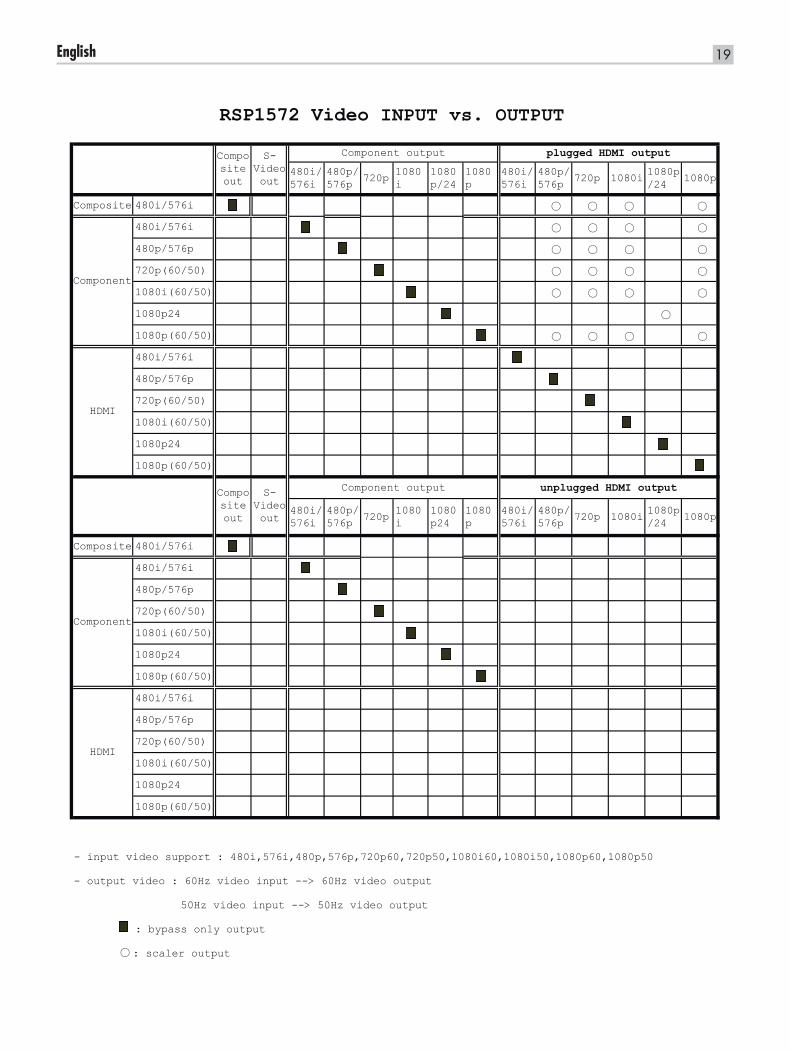
- input video support : 480i,576i,480p,576p,720p60,720p50,1080i60,1080i50,1080p60,1080p50
- output video : 60Hz video input --> 60Hz video output
50Hz video input --> 50Hz video output
: bypass only output
○ : scaler output
Component
HDMI
Compositeout
S-Videoout
Component output unplugged HDMI output
HDMI
RSP1572 Video INPUT vs. OUTPUT
Component output plugged HDMI output
Component
Compositeout
S-Videoout
20 RSP-1572 SURROUND SOUND PROCESSOR
Audio Inputs and OutputsThis Rotel processor provides both analog and digital audio connections.
Tuner Inputs d A Left/Right pair of RCA analog audio inputs for connecting an AM/FM tuner.
VIDEO 1–6 Audio Inputs g Six pairs of RCA inputs (VIDEO IN 1–6) provide connections for Left/Right analog audio signals from six additional source components. These inputs have corresponding video inputs and are used for VCRs, satellite TV tuners, DVD players, etc. However, they may also be used for additional audio only components, simply by omitting the corresponding video connections.
VIDEO Out Audio Output h One pair of RCA jacks (VIDEO OUT) provide connections for sending line level left and right analog audio signals for recording to a VCR.
This connection can be assigned to any analog audio connection.
CD Inputs f A Left/Right pair of RCA analog audio inputs for connecting a CD player .
MULTI Inputs j A set of RCA inputs accept up to 7.1 channels of analog signals from a DVD-A or SACD player. There are inputs for FRONT L & R, CENTER, SUB, REAR L & R, and CENTER BACK 1 & 2 or FRONT VERTICAL HEIGHT L & R in a Dolby PLIIz setup.
These inputs bypass all digital processing in the processor and are routed directly to the Volume control and preamp outputs.
There are two subwoofer options for the MULTI input. Normally, the .1 channel input is passed through directly to the subwoofer output. An optional bass redirect feature duplicates the seven main channels, sums them, and sends this mono signal through a 100Hz analog low filter to the subwoofer output. This provides an unaltered analog bypass for the seven main channels along with a subwoofer signal derived from those channels.
Preamp Outputs k A group of ten RCA analog audio outputs sends the RSP-1572’s line level output signals to external amplifiers and powered subwoofers. These outputs are variable level, adjusted by the RSP-1572’s volume control. The ten connectors provide output for: FRONT L & R, CENTER 1 & 2, SURROUND (REAR) L & R, CENTER BACK CB1 & CB2(or FRONT VERTICAL HEIGHT L & R), and SUBWOOFER 1 & 2.
Note: Depending on your system configuration, you may use some or all of these connections. For example, if you only have one center channel, connect it to the CENTER 1 output. If you only have one center back channel, connect it to the CB1 output.
Digital Inputs t The RSP-1572 accepts digital inputs from source components such as CD players, satellite TV tuners, and DVD players. The built-in digital processor senses the correct sampling rates.
Note: With a digital input connection, the processor will be used to decode the signal, rather than the source component’s internal decoders. You must use digital connections for a DVD player that supplies a Dolby Digital or DTS signal; otherwise the processor will not be able to decode these formats.
There are seven digital inputs on the rear panel, three coaxial and four optical, as well as the HDMI Audio input that is carried by the HDMI cables along with the digital video signals. These digital inputs can be assigned to any of the input sources using the INPUT SETUP screen during the setup process. For example, you can assign the COAXIAL 1 digital input connector to the VIDEO 1 source and the OPTICAL 2 digital input to the VIDEO 3 source. By default, the source input buttons are factory configured to select the following inputs:
CD: Digital Optical 1Tuner: AnalogVideo 1: HDMI Audio (HDMI 1)Video 2: HDMI Audio (HDMI 2)Video 3: HDMI Audio (HDMI 3)Video 4: HDMI Audio (HDMI 4)Video 5: Digital Coaxial 1Video 6: Digital Optical 2
Note: When using digital connections, you may also want to make the analog audio input connections described previously. The analog connection is necessary to send an analog Video and Audio signal to Zones 2, 3 & 4.
Digital Outputs y The RSP-1572 has two digital audio outputs (one coaxial and one optical) to send the digital signal from any of the digital inputs to a digital recorder or outboard digital processor. When a digital input source signal is selected for listening, that signal is automatically sent to both digital outputs for recording.
USB Audio Connection 4 Music storage devices can be accessed by the unit through this input. Music storage devices such as MP3 players, iPod, iPhone, USB memory sticks or any other form of memory devices with USB interface can be connected to the unit through the front USB socket. The unit will automatically search music files from the connected storage device.
Note: When connecting iPod or iPhone to the front USB, the controls on the iPod/iPhone remain active. Only simple controls such as PLAY, STOP, SKIP TRACK can be controlled by the RSP-1572.
The front USB can also accept a USB Bluetooth dongle (supplied). This allows you to stream music from your Bluetooth device, i.e. mobile phone. Insert the USB Bluetooth dongle into the front USB, the display will show “READY” status. From your device (mobile phone etc..) activate Bluetooth and allow it to search for other Bluetooth devices and it will find “Rotel Bluetooth”. Select “Rotel Bluetooth” and it will ask you to enter a password. Enter “0000” and accept. The RSP-1572 will recognize a device is attempting to connect to it, and will display this information on the OSD. Press ENT key on the remote to accept. The “READY”
21English
Note: The IR signals from the REM IN EXT and REM IN ZONE 2–4 jacks can be relayed to source components using external IR emitters or hard-wired connections from the IR OUT jacks. See the following section for additional information.
IR OUT Jacks [ The IR OUT 1 & 2 jacks send IR signals received at the REM IN ZONE 2–4 jacks or the REM IN EXT jack to an infrared blaster or emitter placed in front of a source component’s IR sensor . In addition, the IR OUT can be hard-wired to Rotel CD players, DVD players, or tuners with a compatible connector.
These outputs are used to allow IR signals from the three remote zones to be sent to the source components, or to pass along IR signals from a remote in the main room when the sensors on the source components are blocked by installation in a cabinet.
See your authorized Rotel dealer for information on IR emitters and repeater systems.
Rear Mini USB Socket l Remote IR OUT p The Rear USB connector is for connecting to a computer’s USB socket. The RSP-1572 has the ability to learn other component’s remote codes and be programmed to send them via the Remote IR outputs to various components. This program requires setup on a computer.
For additional information on this feature, please contact your authorized Rotel dealer.
Computer I/O u This Rotel unit can be operated from a computer with audio system control software from third-party developers. This control is accomplished by sending operating codes from the computer via a hard-wired RS-232 serial connection. In addition, the RSP-1572 can be updated using special software from Rotel.
The COMPUTER I/O input provides the necessary network connections on the rear panel. It accepts standard RJ-45 8-pin modular plugs, such as those commonly used in 10-BaseT UTP Ethernet cabling.
For additional information on the connections, cabling, software, and operating codes for computer control or updating of the unit, contact your authorized Rotel dealer.
status will change to “RUNNING” and you can start streaming music to the RSP-1572.
Note: Not all Bluetooth dongles will operate with the unit. Please use the dongle supplied by Rotel.
Other ConnectionsAC Input ; Your Rotel processor is configured at the factory for the proper AC line voltage in the country where you purchased it (USA: 120 volts/60Hz AC or CE: 230 volts/50 Hz AC ). The AC line configuration is noted on a decal on the back of your unit. Plug the supplied cord into the AC INPUT receptacle on the back of the unit.
Note: Memorized settings and video labels are preserved indefinitely, even if the unit is disconnected from AC power.
Master Power Switch a The large rocker switch on the rear panel is a master power switch. When it is in the OFF position, power to the unit is completely off. When it is in the ON position, the front panel STANDBY and remote control ON/OFF buttons can be used to activate the unit or put it into standby mode.
12V TRIGGER Connections o Many Rotel amplifiers offer the option of turning them on and off using a 12 volt trigger. These six connections provide this 12 volt trigger signal from the processor. When the unit is activated, a 12 volt DC signal is sent from these jacks to the amplifiers to turn them on. When the processor is put in STANDBY mode, the trigger signal is interrupted and the amplifiers turn off.
To use the remote turn on feature, connect one of the RSP-1572’s 12V TRIG OUT jacks to the 12 volt trigger input of a Rotel amplifier, using a cable with mono 3.5mm mini-plugs on both ends. The +12 V DC signal appears at the “tip” connector.
Note: The 12V Trigger outputs are configured to turn on in various combinations only when specific input sources are activated. See the INPUT SETUP and ZONE 2–4 SETUP menus in the Setup section of this manual for details
REM IN Jacks \ Four 3.5 mm mini-jacks (labeled EXT, ZONE 2, ZONE 3, and ZONE 4) receive command codes from a third-party infrared receiver or Rotel remote zone keypad, These remote IR inputs are used when the IR signals from a hand held remote control cannot reach the front panel IR sensor.
EXT: The EXT jack is used with an outboard IR receiver to duplicate the front panel IR sensor. This feature is useful when the unit is installed in a cabinet and the front panel sensor is blocked or when IR signals need to be relayed to other components.
ZONE: The ZONE 2, 3, or 4 jacks are used with IR repeater systems to receive signals from IR control systems in remote locations. For example, remote control signals sent to the ZONE 2 jack control the ZONE 2 features of the RSP-1572 and can be relayed to other components.
Consult your authorized Rotel dealer for information on external receivers and the proper wiring of 3.5mm mini-plugs to fit the REM IN jacks.
22 RSP-1572 SURROUND SOUND PROCESSOR
Connecting Monitor
----HDTV Monitor/Video Recording See Figure 4
A key feature of this Rotel processor is that it can send a video signal to any HDTV monitor in exactly the format that best matches the native mode and resolution of the TV.
Digital HDTVs, such as LCD, LED and Plasma flat-screens, display digital signals directly. These TVs should be connected to the processor using the HDMI digital outputs.
The component outputs of the RSP-1572 can be connected to an analog HDTV display, but no OSD menu will be available.
HDMI digital connection: Connect one end of an HDMI cable to the HDMI OUT connector on the back of the processor. Connect the other end of the cable to the HDMI input connector on the back of the HDTV.
You can usually connect the HDMI output of the processor to a monitor with DVI-D inputs by using an appropriate HDMI-DVI adapter.
Note: In order for HDMI signals to be displayed properly, the TV monitor must be compatible with HDCP copy protection.
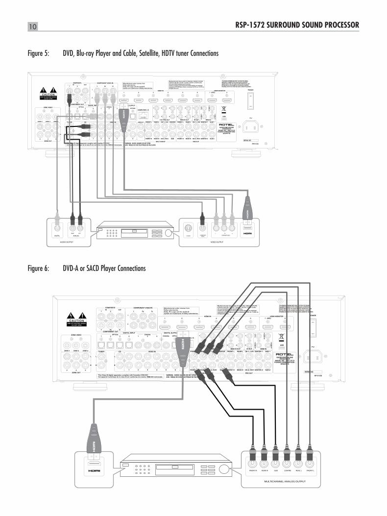
Connecting DVD, Blu-ray Player and Cable, Satellite, HDTV tuner See Figure 5
DVD or Blu-ray player and TV tuner connections can be made using HDMI, Component Video, or Composite video connections.
Note: You must use either HDMI or Component Video connections for a progressive scan or high definition player. You must make an analog audio connection if you want to send signals to Zone 2,3 & 4.
For HDMI connections: Connect an HDMI cable from the output of the Blu-ray player to one of the HDMI IN 1–6 inputs on the processor.
For Component Video connections: Connect a set of three Component Video cables from the output of the DVD player to one of the COMPONENT VIDEO 1–2 inputs on the processor . Make sure to connect the Y output to the Y input, the PB output to the PB input, and the PR output to the PR input.
For Composite Video connections: Connect an RCA-RCA video cable from the output of the DVD player to one of the COMPOSITE IN 1–2 inputs on the processor.
Note: Use the INPUT SETUP screen to assign the video input you have used to the Blu-ray source.
Digital audio connection: Connect the digital output of the DVD player to any one of the DIGITAL IN OPTICAL 1–4 or DIGITAL IN COAXIAL 1–3 inputs on the processor. An HDMI cable carries both digital video and digital audio signals; therefore, no separate digital audio connection needs to be made.
Note: Use the INPUT SETUP screen to assign the digital input to the same video input source used above.
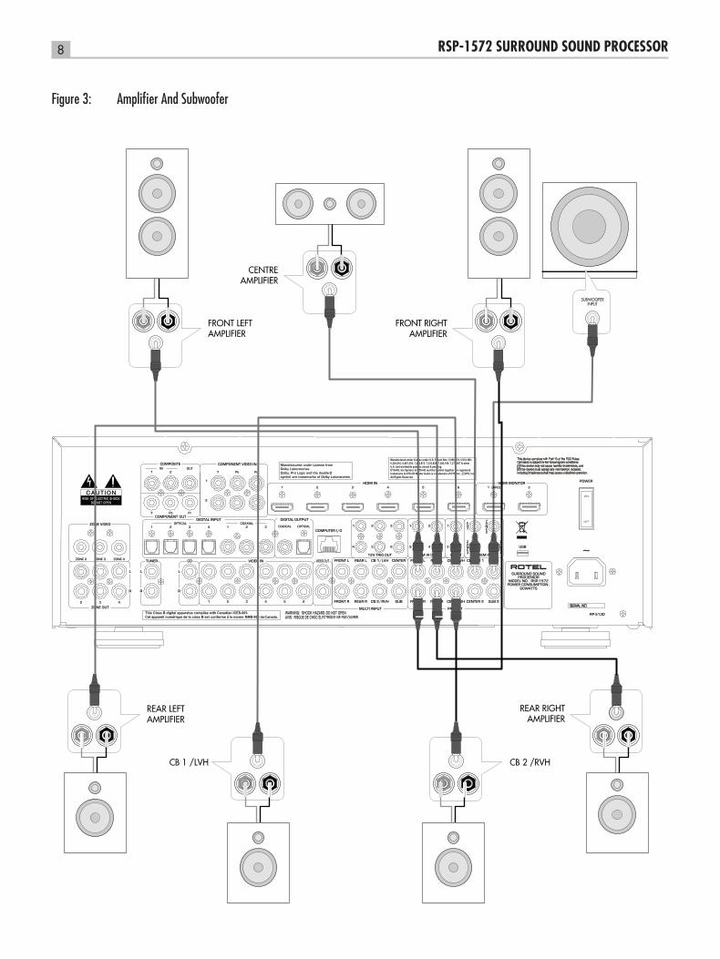
MAKING CONNECTIONSConnecting Amplifier See Figure 3
The RSP-1572 has preamp outputs for connections to power amplifiers to drive up to eight speakers in a 5.1, 6.1, or 7.1 channel surround sound audio system: right/left front channels, 2 center channels, right/left surround channels, and two center back (or front height) channels . In addition, there are two subwoofer outputs.
To hook up amplifiers, connect an audio cable from each PREOUT jack to the input of the amplifier channel that will power the corresponding speaker. For example, connect the FRONT L output to the amplifier channel driving the front left speaker. In a full home theater system, you will make up to seven different connections in addition to the subwoofer. These connections for a 5.1channel system are labeled FRONT L and FRONT R, CENTER, and REAR L and REAR R. There are two CENTER jacks; use either jack for a single center channel, or both if you have two center channels. In six or seven channel systems, make one or two additional connections for Center Back channel(s). These jacks are labeled CB1/LVH and CB2/RVH. Use CB1 for a single center back channel.
In a Dolby PLIIz system, you can have Left Vertical Height (LVH) or Right Vertical Height (RVH) speakers instead of CB1 and CB2
Make sure that you have each output connected to the correct amplifier channel:
1. Connect the front left amplifier to the FRONT L jack.
2. Connect the front right amplifier to the FRONT R jack
3. Connect the center channel amplifier to the CENTER 1 or CENTER 2 jack.
4. Connect the surround left amplifier to the REAR L jack.
5. Connect the surround right amplifier to the REAR R jack.
6. Connect the center back left/LVH amplifier to the CB1/LVH jack.
7. Connect the center back right/RVH amplifier to the CB2/RVH jack.
After you have connected the preamp outputs, you need to configure the RSP-1572 for the size and style of speakers in your system and calibrate the relative volume levels of the speakers using the built-in test tones. See the Setup section of this manual.
Connecting a Subwoofer See Figure 3
To hook up a powered subwoofer, connect a standard RCA audio cable from either of the two PREOUT jacks labeled SUB to the input on the subwoofer’s power amp. Both SUB outputs provide the same signal. Use either connection for a single subwoofer . Use both connections to hook up two subwoofers.
After you have connected the subwoofer, you need to configure the unit to use the subwoofer and calibrate the relative volume level of the subwoofer using the built-in test tones. See the Setup section of this manual.
23English
Optional analog audio connection: If you want to record the audio signal from the DVD player, connect the left and right analog outputs from the DVD player to one pair of VIDEO IN 1–6 audio input jacks. Make sure that you connect the right channel to the R input jack and the left channel to the L input jack.
Connecting DVD-A or SACD Player See Figure 6
In most cases, DVD-A, SACD, and other external multichannel processors are connected to the processor by sending decoded analog audio signals using RCA cables. A DVD-A player with HDMI outputs can send digital signals directly to the processor for decoding.
Analog Connections: To hook up a DVD-A, an SACD player (or any external surround decoder) with analog connections, use audio RCA cables to connect the outputs of the player to the RCA jacks labeled MULTI INPUT, making sure that you observe proper channel consistency, i.e. connect the right front channel to the FRONT R input, etc.
Depending on your system configuration, make six connections (FRONT L & R, SURROUND L & R, CENTER, and SUBWOOFER), seven connections (adding a CENTER BACK connection), or eight connections (adding two CENTER BACK or Vertical Height connections).
The MULTI inputs are analog bypass inputs, passing signals directly through to the Volume Control and preamp outputs, bypassing all of the digital processing. The processor provides an optional bass redirect feature that duplicates the seven main channels and passes them through an analog 100 Hz low pass filter, creating a summed mono subwoofer output derived from the main channels. See the INPUT SETUP menu in the Setup section of this manual for details on bass redirect feature.
HDMI digital connection: If the DVD-A player has HDMI outputs, simply connect an HDMI cable to the output of the player to one of the HDMI 1–6 inputs on the processor. This cable sends the video signal from the player along with a digital audio signal. The DVD-A multichannel decoding is handled by the processor.
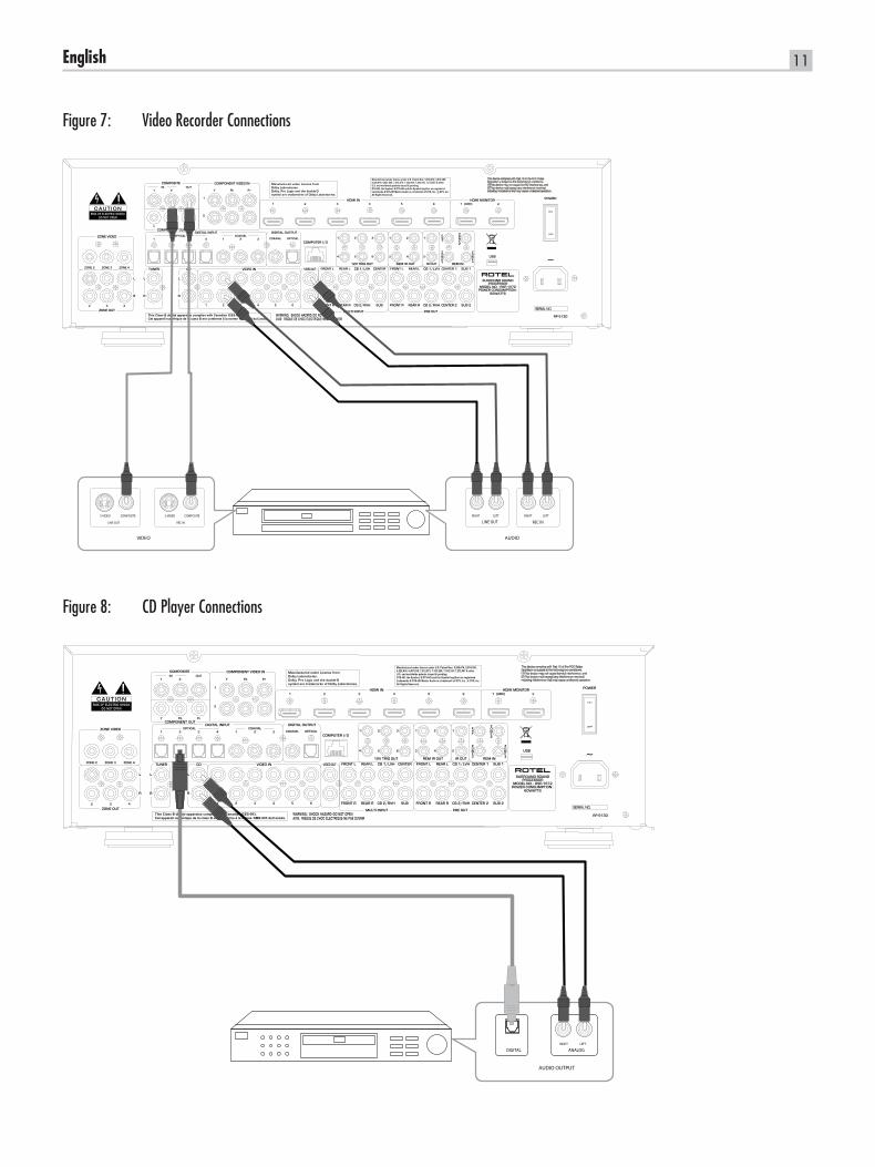
Connecting Video Recorder See Figure 7
VCR connections can be made to any VIDEO inputs.
Composite connections: Connect an RCA video cable from the output of the VCR to the COMPOSITE IN 1 input. Connect an RCA video cable from the COMPOSITE OUT jack to the VCR inputs.
Audio Connections: Connect the left and right analog outputs from the VCR to the VIDEO IN 1 audio inputs. Connect the left and right VIDEO OUT audio outputs to the analog inputs on the VCR.
Optional Digital Audio: For a digital recording device, connect the digital output of the recorder to one of the OPTICAL IN or COAXIAL IN digital inputs on the processor. Use the INPUT SETUP screen to assign that digital input to the VIDEO source (VIDEO 1, 2, or 3) used for the previous connections. If the recording device accepts a digital recording input, connect one of the OPTICAL OUT or COAXIAL OUT connections to the digital input of the recorder.
Connecting CD PlayerSee Figure 8
Connect the digital output of the CD player to any of the Optical or Coax digital inputs on the processor. Use the INPUT SETUP menu to assign the digital input to the CD (the default is OPTICAL 1).
Optional: Connect the left and right analog outputs from the CD player to the AUDIO IN jacks labeled CD (left and right). This option uses the CD player’s D/A converters; however, this may result in an extra A/D and D/A conversion step.
There are typically no video connections for a CD Player and no video input is assigned to the CD, as a default setting.
Connecting Audio Recorder See Figure 9
Connect the left and right analog outputs from an audio tape deck to the VIDEO IN audio jacks (left and right).
Connect the Left/Right VIDEO OUT jacks to the inputs on the audio tape deck.
Optional: For a digital recording device, connect the digital output of the recorder to one of the OPTICAL IN or COAXIAL IN digital inputs on the processor. Use the INPUT SETUP screen to assign that digital input to an audio source. If the recording device accepts a digital recording input, connect one of the OPTICAL OUT or COAXIAL OUT connections to the digital input of the recorder.
No video connections are required for an audio recording device.
Connecting AM/FM TunerSee Figure 10
Digital audio connection: If using an HD Radio or other digital tuner, connect the digital output of the tuner to any one of the DIGITAL IN OPTICAL 1–4 or DIGITAL IN COAXIAL 1–3 inputs on the RSP-1572.
Note: Use the INPUT SETUP screen to assign the digital input to TUNER source.
Analog audio connection: If using an analog AM/FM tuner or if you want to record the audio signal from the tuner, connect the left and right analog outputs from the tuner to the pair of audio input jacks labeled. TUNER on the RSP-1572. Make sure that you connect the right channel to the R input jack and the left channel to the L input jack.
There are typically no video connections for an AM/FM tuner and no video input is assigned by default.
Connecting USB Audio/iPod/iPhone See Figure 11
Connect the iPod/iPhone or MP3 player to the front USB socket. Select tracks to be played from the iPod/iPhone the Rotel processor will decode the signal and play the music.
24 RSP-1572 SURROUND SOUND PROCESSOR
Zone Outputs (ZONE 2,3,4)
This Rotel processor has connections for three independent remote zones.
For audio connections to a remote zone, connect the left and right ZONE 2,3, or 4 jacks to the left and right channels of a remote zone amplifier with an RCA audio cable.
For video connections to a remote zone, connect the ZONE 2,3, or 4 VIDEO OUT jacks to the input of a TV in the remote zone using a Composite Video cable.
For control of the unit from a remote zone: connect a remote zone IR repeater to the ZONE 2, ZONE 3, or ZONE 4 REM IN jack using a cable terminated with 3.5mm plugs.
Operating the RSP-1572 Considering its large number of features, settings and options, this Rotel RSP-1572 is remarkably easy to operate. The key to operating the unit is its system of On-Screen Displays (OSD) which guide you through various choices.
To guide you through the operation of the unit, this section of the manual starts with explaining the basic layout and function of the front panel and the remote control. Then, we explain the basic operations such as turning the unit on and off, adjust volume, selecting a source for listening, etc. Following that is a detailed explanation of surround sound modes and how to configure the unit for various types of recordings. Finally, there are instructions for additional features and zone operation. All of these are features that may be used in normal operation. The last section of the manual (Configuration) details options that may be selected during initial setup and configuration of the unit, many of which will be set once and left untouched.
Throughout this manual, numbers in square boxes refer to the main unit illustration at the front of this manual. Letters refer to the remote handset illustration. When both appear, the function is found on both the unit’s front panel and on the remote. When only one appears, that function is found either only on the main unit, or only on the remote.
Front Panel OverviewThe following is a brief overview of the controls and features on the front panel of the unit. Details concerning the use of these controls are provided in subsequent sections of this manual describing various tasks.
Front Panel Display 2
The FL Display on the front panel shows the source selected and type of audio mode the unit is in.
Remote Sensor 2
This sensor receives IR signals from the remote control. Do not block this sensor. The IR sensor is behind the front panel display.
Note: The remainder of the buttons and controls on the front panel are described in the Overview of Buttons and Controls section.
Remote Control OverviewThe RSP-1572 is supplied with an easy to use remote control RR-CX94. The unit can be set to IR code 1 or IR code 2 in case the unit is conflicting with other Rotel remote codes. Push the TUN key and 1(2) at the same time sets the remote control into IR code 1(2). Point the remote to the RSP-1572 and press 1(2) for 5 seconds sets the RSP-1572 in IR code 1(2) . The factory default is IR code 1.
The supplied remote can also be set to control zones 2,3 and 4 from the main room by setting the remote to IR codes 3, 4 or 5. Set to IR code 3, 4, or 5 by pressing TUN key and 3 (4 or 5) at the same time. IR code 3 is for Zone 2. IR code 4 is for Zone 3 and IR code 5 is for Zone 4 operation.
25English
You can also set the CD codes for PLAY, STOP, FAST FORWARD, REV etc, from the factory default IR code 1 to 2, if you find the unit is interfering with other Rotel CD players in your system.
To change the CD code, point the remote at the unit and press “CD” and 2 (1) keys at the same time. Release the “CD” key and continue to press the 2 (1) key for more than 5 seconds until the unit changes the code.
Overview of Buttons and ControlsThis section provides a basic overview of the buttons and controls on the front panel and the remote control. Detailed instructions on the use of these buttons are provided in the more complete operating instructions in the following sections.
STANDBY 1 and Power ON/OFF Buttons A The front-panel STANDBY button and the remote control ON/OFF button activate or deactivate the unit. The rear panel master POWER switch must be in the ON position for the remote standby function to operate.
VOLUME Knob and VOLUME +/- Buttons 6 C The VOLUME +/- buttons on the remote and the large rotary control on the front panel provide the master VOLUME control, adjusting the output level of all channels simultaneously.
DISPLAY (DISP) Button D Push this toggle button to display the current Audio and Video source, input mode and output mode. To change Dynamic Range, push the DISP button then push DOWN and Left/Right keys to adjust.
RCVR SETUP Button E Navigating and Select (ENT) keys F The RCVR SETUP button pulls out the OSD on the TV. Use the navigation keys UP/DOWN/Left/Right and ENT to access the various menus.
Note: The MENU button on the remote control will not operate with the RSP-1572 without additional programming by your dealer.
MUTE Button =B Push the MUTE button once to turn the sound off. An indication appears in the front panel and on-screen displays. Press the button again to restore previous volume levels.
INPUT Buttons 378M This button on the front panel can be used to change sources.
ZONE Button 9 This button serve as a standby button for the currently selected remote zone, toggling the zone on or off.
SEL Button 0J This button can be used to select the desired zone fro additional changes such as changing the input, adjusting the volume, or turning a remote zone on or off. Repeatedly press the button until the desired zone appears in the front panel: RECORD > ZONE 2 > ZONE 3 > ZONE 4. Once the desired zone appears, you have 10 seconds to make the desired change. Change the input selection by pressing an INPUT button. When ZONES 2-4 appear, you can also adjust the volume, or turn the zone on or off by pressing the ZONE button.
MODE buttons - SUR+ J The MODE buttons/SUR+ button serve to display surround mode information of current listing/viewing media, which can be set when selecting input source. On the remote, press SUR+ key, then use the Left/Right navigation keys to change the mode.
Other buttons on the remote and front panel can directly access specific modes.
2CH: change the audio mode to STEREO, DOWN MIX or BYPASS.PLIIx MODE: change the Pro-Logic mode.DSP: Changes the DSP decode mode (analog) from DSP1 - 4, 5/7 CH Stereo.PLCM: toggles the audio mode to Pro Logic Cinema or Music.
Playback buttons L These buttons provide basic control functions for iPod/USB AUDIO playback.
PLAY / button: Start playing the selected mediaSTOP . button: Stop current playing track, press / button to resume Push STOP key for 5 seconds to safely remove the USB device from the front socket.PAUSE , button: Temporarily suspend playPREVIOUS { button: One push -Skip to start of current track Two pushes Skip to previous track.NEXT } button: Skip to next track.
RND Button I This button can be used for the front USB connection and put the music played in random/shuffle mode.
P-EQ Button/Knobs5D Used to display the EQ Frequency level and GAIN. Also can be used for temporary adjustments of EQ. Push P-EQ button and use the UP/Down keys to adjust GAIN value. Use the Left/Right keys to skip to the next frequency. From the front panel, push the FREQ knob to bring up the EQ value. Turn the knob to change the frequency. Turn the parametric EQ knob to adjust the GAIN value.
For permanent EQ and GAIN adjustments, please enter the value in the EQ setup menu.
SPKR Button D This button can access the various speaker setting and adjust the output level for each speaker in the system. Use the navigations keys to change values. This is only a temporary change. To make permanent adjustments, please access the TEST TONE setting from the OSD.
MEM Button H This button does not operate with the RSP-1572.
Party Mode: Selecting the Same input for all outputs 90J You may wish to have the same input for listening, recording and all of the remote zones. The RSP-1572 makes this configuration easy, (called party mode) by linking inputs for recording and remote zones.
26 RSP-1572 SURROUND SOUND PROCESSOR
To activate Party Mode, Press and hold ZONE button on the front panel for 3 seconds. The words PARTY ON appear briefly in the display and the ZONE icon flashes for 10 seconds. The record input selection and all remote zones input selections will be displayed as SOURCE, indicating that they are linked to the input selected for listening. While in party mode, a “P” indicator remains in the front panel display.
To cancel Party mode, press and hold the SEL button on the front panel or remote for at least 3 seconds.
SURROUND SOUNDTo get the best performance from your unit, it helps to understand the many surround sound formats available today, to know which decoding process to use for a particular recording, and how to select it. This section provides basic background information about surround sound formats. The following sections provide detailed operating instructions for automatic and manual selection of surround modes.
Overview of Surround FormatDolby Surround & Dolby Pro Logic II The most widely available surround sound format for consumer audio/video is Dolby Surround®, available on nearly all commercial VHS tapes, many television broadcasts, and most DVDs. Dolby Surround is the consumer version of the analog Dolby Stereo system first introduced in the film industry in 1972. It is a matrix-encoding system that records front left, front center, front right, and a mono surround channel into a 2-channel stereo recording. During playback, a Dolby Pro Logic® or Pro Logic II decoder extracts each channel and distributes it to the appropriate speakers.
The original Dolby Pro Logic decoder delivered a mono signal with reduced high-frequency content to the surround speakers. A more advanced decoder in the processor, Dolby Pro Logic II, increases the separation and frequency response of the surround channels for significantly improved performance with Dolby Surround encoded recordings.
Dolby Pro Logic II decoding should be used for any analog recording labeled “Dolby Surround” or any Dolby Digital 2.0 soundtrack. Dolby Pro Logic II does a superb job deriving surround sound from conventional 2-channel stereo recordings, using phase relationships to extract front, right, center, and surround channels. A “music mode” makes Pro Logic II an excellent choice for audio CDs.
Dolby Digital In 1992, a digital recording system, called Dolby Digital, was first used in the film industry. Dolby Digital is a recording/playback system that uses compression techniques to store large amounts of audio data efficiently, much like the JPEG format stores large photographs in small files on a computer. Because it is capable of performance beyond that of audio CDs and can tailor its output for a wide ranges of system configurations, Dolby Digital is the standard audio format for DVDs and for digital television broadcasting in the United States.
The Dolby Digital system can be used to record up to six discrete audio channels, but can also be used for fewer. For example, a Dolby Digital 2.0 soundtrack is a digital 2-channel recording of a matrix encoded
Dolby Surround soundtrack. To play a Dolby Digital 2.0 recording, use Dolby Pro Logic II decoding as previously described.
The most common use of Dolby Digital in newer films, in both the film industry and in home theater, is Dolby Digital 5.1. Instead of encoding multiple surround channels on a two-channel recording, Dolby Digital 5.1 records six discrete channels: front left, front center, front right, surround left, surround right, and a Low Frequency Effects (LFE) channel containing ultra-low bass signals intended for a subwoofer. A Dolby Digital decoder extracts the channels from the digital bitstream, converts them to analog signals and routes them to the appropriate amplifiers and speakers. All channels provide full frequency response with total separation between all channels and large dynamic range capability. A Dolby Digital 5.1 soundtrack can provide more impressive surround sound than matrix Dolby Surround.
Decoding of Dolby Digital 5.1 soundtracks is automatic. When the RSP-1572 detects a Dolby 5.1 signal on one of its digital inputs, it activates the proper processing. Keep in mind that Dolby Digital is only available from digital sources (a DVD, a LaserDisc, or a Digital TV/Cable/SAT tuner). Also, you must connect the source with a digital cable (coax or optical) to an active digital input on the processor .
Note: Many DVDs have a Dolby Digital 2.0 matrix soundtrack as the default, which should be decoded with Pro Logic II. The Dolby Digital 5.1 soundtrack may have to be selected as an option from the setup menus at the beginning of the DVD. Look for a Dolby Digital 5.1 selection under “Audio” or “Languages” or “Setup Options” when you insert the disc.
DTS 5.1 & DTS 96/24DTS® (Digital Theater Systems) is an alternative digital format competing with Dolby Digital in both movie theaters and home theater markets. The basic functions of the DTS system are similar to those of Dolby Digital (for example, 5.1 discrete channels), however the technical details of the compression and decoding processes differ somewhat and a DTS decoder is required.
A recent extension of the DTS encoding system is DTS 96/24 and the 6.1-channel version DTS-ES 96/24. These recordings provide the performance of a 96kHz sampling rate while still using the actual 48kHsampling rate of standard DTS discs.
Like Dolby Digital, DTS can only be used on a digital recording and, therefore, is only available for home use on LaserDiscs, DVDs, or other digital formats. To use the RSP-1572’s DTS decoder, you must connect your DVD player to the unit’s digital inputs. As with Dolby Digital 5.1, detection and proper decoding of DTS 5.1 signals is automatic.
Note: DVDs with a DTS soundtrack almost always have it configured as an option to the standard matrix Dolby Surround format. To use DTS, you may have to go to the setup menus at the beginning of the DVD and select “DTS 5.1” instead of “Dolby Surround” or “Dolby Digital 5.1”. In addition, many DVD players have the DTS digital bitstream turned off by default and cannot output a DTS soundtrack (even if selected on the disc’s menu) until you activate the player’s DTS output. If you hear no sound the first time you attempt to play a DTS disc, go to the DVD player’s configuration menus and turn on the DTS bitstream. This is a one-time setting and need only be done once.
27English
DTS Neo:6This Rotel processor features a second type of DTS surround sound decoding: DTS Neo:6. This decoding system is similar to Dolby Pro Logic II and is designed for playback of any 2-channel stereo recording, either matrix-encoded or not. The Neo:6 decoder can be used with any conventional 2-channel source such as a stereo TV or FM broadcast or a CD. It can also be used as an alternative method of decoding matrix-encoded Dolby Surround recordings or TV broadcasts. Activate the DTS Neo:6 decoding with the PLIIx MODE button on the front panel or with the SUR+ key on the remote as detailed later in this section. DTS Neo:6 is not used with DTS 5.1 digital sources and the button need not be pressed for those recordings.
Dolby Digital Surround EX DTS-ES 6.1 and 7.1 Channel SurroundIn 1999, the first Dolby Digital soundtrack was released to theaters with an additional center back surround channel, intended to increase the directional effects from behind the audience. This additional surround channel is encoded into the two existing surround channels in Dolby Digital 5.1, using a matrix encoding process similar to that used previously in Dolby Surround. This new extended surround capability is called Dolby Digital Surround EX.
DTS has added a similar capability for recording this extended surround information called DTS-ES® 6.1 Matrix. They have also taken it one step further and developed the capability to record this extended surround information as a discrete channel in a system called DTS-ES® 6.1 Discrete.
All of these systems are extensions of the existing Dolby Digital 5.1 and DTS 5.1 digital surround sound formats. Users with one center back speaker (a 6.1 configuration) or two center back speakers (a 7.1 configuration) can take advantage of this extended surround information. On traditional 5.1 channel systems, Dolby Digital Surround EX or DTS-ES 6.1 discs sound exactly the same as 5.1 channel discs in each respective format.
If you have configured your system with one or two center back speakers, decoding of DTS-ES discs is automatic, just as it is with standard DTS soundtracks. Likewise, decoding of Dolby Digital Surround EX discs is automatic with one exception. Some Surround EX titles do not have the detection “flag” encoded on the disc. To activate the Dolby Digital Surround EX features for these discs (or for standard 5.1 channel Dolby Digital discs), you must manually activate Dolby Surround EX processing.
Dolby Pro Logic IIx 6.1 and 7.1 Channel SurroundThis technology from Dolby uses advanced matrix decoding for the surround channels in a 6.1 channel or 7.1 channel system. Working with any 2.0 channel or 5.1 channel recording, Dolby Pro Logic IIx processing distributes the surround channel information among three or four surround channels, with a Music mode optimized for musical recordings and a Cinema mode optimized for film soundtracks
Dolby Pro Logic IIz 7.1 Height SurroundThe latest technology from Dolby delivers enhanced effects through the addition of front height speakers. These added channels create a lifelike soundstage It identify and decode the spatial cues that occur naturally in all content whether stereo, 5.1, music CD 5.1 and 7.1
channel sources then process ambient sound effects such as wind or rain fall and direct them to the front height speakers.
Rotel XS 6.1 and 7.1 Channel SurroundThis RSP-1572 also features Rotel XS (eXtended Surround) processing provides extended surround performance on 6.1 and 7.1 channel systems. The key benefit of Rotel XS is that it works at all times with all multichannel digital signals, even those that might not otherwise activate Dolby Digital EX or DTS-ES surround decoding for the center back channel(s). Always available when center back speaker(s) are configured in the system setup, Rotel XS decodes the surround channels and distributes the extended surround channels to the center back speaker(s) in a way that tends to create a diffuse surround effect. Rotel XS works with matrix-encoded surround signals (such as non-flagged DTS-ES and Dolby Surround EX discs) as well as digital source material that is not Dolby Surround EX encoded (such as DTS 5.1, Dolby Digital 5.1, and even Dolby Pro Logic II decoded Dolby Digital 2.0 recordings).
Dolby Digital PlusBuilt on Dolby Digital, the multichannel audio encoding standard for DVD and HD broadcasts, Dolby Digital Plus was designed for the new high-resolution delivery formats, but remains compatible with current A/V processors. It is supported by the HDMI digital connection standard. Dolby Digital Plus can provide up to 7.1 channels with discrete channel output at higher bit rates than Dolby Digital. Dolby Digital Plus is an optional sound format for Blu-ray, and a mandatory inclusion for HD DVD discs.
Dolby True HDDolby TrueHD is based on lossless coding technology to deliver studio master-quality sound. Dolby TrueHD supports up to eight full-range channels (the maximum allowed by Blu-Ray) of 24-bit/192 kHz audio. Dolby TrueHD is supported by the HDMI v1.3 digital connection.
Additional features include Dialogue Normalization, which maintains the same volume level when changing to other Dolby Digital and Dolby TrueHD programming, and Dynamic Range Control (or ‘Night Mode’), reducing peak volume levels to allow late-night viewing of high-energy surround sound without disturbing others. Dolby TrueHD is an optional sound format for Blu-ray Disc, and a mandatory format for HD DVD.
DTS-HD Master Audio &DTS-HD High Resolution AudioLike Dolby’s TrueHD, DTS-HD Master Audio is an advanced lossless audio codec which is an optional sound format for Blu-ray discs, again delivering the original recorded sound ‘bit-for-bit’. It is also an optional format for HD-DVD disc recordings. DTS-HD Master Audio is compatible with the HDMI v1.3 connection standard, and supports a maximum of 192kHz sampling at 24-bit audio in 5.1 CH mode, and 24bit/96KHz resolution for eight channels in multichannel mode. A DTS-HD capable processor can also decode discs recorded with DTS-HD High Resolution Audio. This format is not lossless but delivers virtually all of the original recording, though not literally identical to the studio master .
DSP Music ModesUnlike all of the formats mentioned above, the RSP-1572 offers four surround modes that are not part of a specific recording/playback system. These modes (DSP 1–4) use digital signal processing that adds special acoustic effects to any signal. DSP processing can be used with Dolby Surround recordings, Dolby Digital recordings, CDs, radio broadcasts, or
28 RSP-1572 SURROUND SOUND PROCESSOR
any other source material; however, typically DSP settings would be used with source material for which there is no specific surround decoder .
The four DSP MODES in the processor use digital delay and reverberation effects to simulate progressively larger acoustic environments with DSP 1 being the smallest type of venue (such as a jazz club) and DSP 4 being a large venue (such as a stadium). Typically used to add ambience and a sense of space when listening to music sources or other sources that lack surround sound encoding.
2CH/5CH/7CH stereo formatsThe RSP-1572 also provides four modes that disable all surround processing and deliver stereo signals to amplifiers and speakers. The four options are:
2CH Stereo: Turns off the center channel and all surround channels in the system and delivers a conventional 2-channel signal to the front speakers. If the system is configured to route bass signals from the front speakers to the subwoofer , this capability remains in effect.
Analog Bypass: For 2-channel analog inputs, there is a special stereo mode that bypasses ALL of the RSP-1572’s digital processing. The two front speakers receive pure analog stereo full-range signals with no subwoofer crossover, no delay, no level adjustments, and no parametric eq.
5CH Stereo: Distributes a stereo signal to 5.1 channel systems. The left channel signal is sent, unchanged, to the front left and surround left speakers. The right channel is sent to the front right and surround right speakers. A mono sum of the two channels is sent to the center channel speaker.
7CH Stereo: This mode is the same as 5CH Stereo described above except that it also distributes stereo signals to center back speaker(s) installed in the system.
Other Digital FormatsSeveral other digital formats are not surround sound formats at all, but rather systems for digital 2-channel recordings.
PCM 2-channel: This is an uncompressed 2-channel digital signal that is used for standard CD recordings and some DVD recordings, particularly of older films.
DTS Music 5.1 Discs: These discs are a variation of audio CDs that include a DTS 5.1 channel recording. The processor decodes these disc s just like a DTS movie soundtrack when played on a CD player or DVD player with a digital output connection.
DVD-A music discs: Taking advantage of the increased storage capacity of the DVD disc, new high bit rate multichannel audio recordings are available on DVD-A discs. DVD-A discs may include multiple versions of the recording including standard PCM stereo, Dolby Digital 5.1, DTS 5.1, and 96kHz/24 bit (or higher) multi-channel recordings using MLP compression. Several of these formats (standard PCM, Dolby Digital, and DTS 5.1) can be decoded by the processor when the DVD player is connected with a digital cable. However, the existing optical and coax digital audio connection standard does not provide sufficient bandwidth for multichannel high sampling rate MLP recordings. Therefore, you must use the HDMI high-definition digital connection to replay the high-resolution audio soundtrack of DVD-A discs. Alternatively, the high-resolution audio
can be decoded by the DVD-A player and the resulting analog signals sent to the processor’ s MULTI INPUT.
SACD®: This is a proprietary high-resolution audio standard for use on SACD compatible disc players. As with DVD-A discs, the bandwidth is too high for today’s digital connection. Thus, these discs must be decoded by a SACD compatible player, with the output sent to the processor’s MULTI INPUTS.
MP3: MP3 format recordings, often downloaded from the Internet, can be played on portable MP3 players or some disc players that can read CD-ROM discs. These players can be connected to the processor’ s digital inputs, but must output a digital PCM stream.
29English
Automatic Surround ModesDecoding of digital sources connected to the digital inputs is generally automatic, with detection triggered by a “flag” embedded in the digital recording telling the processor what decoding format is required. For example, when Dolby Digital 5.1 or DTS 5.1 channel surround is detected, the processor activates the proper decoding.
The unit will detect DTS-ES Matrix 6.1 or DTS-ES Discrete 6.1 discs and activate DTS-ES® Extended Surround decoding. Dolby Digital Surround EX recordings also trigger automatic decoding (although not all Surround EX DVDs have the necessary flag and may require manually activating Surround EX decoding).
The unit will also detect Dolby True HD and DTS-HD Master Audio automatically.
Likewise, a digital input from a standard compact disc, a DTS 96/24 disc, or DTS-ES 96/24 disc, will be auto-detected and properly decoded to 2CH stereo operation.
Dolby Pro Logic IIx/IIz or Rotel XS processing can be configured to be automatically active in all 6.1 or 7.1 channel systems configured with center back speaker(s) and will ensure proper extended surround decoding of all multichannel digital signals, even those that might not otherwise trigger the proper extended surround mode.
In many cases, the processor will also recognize a digital signal with Dolby Surround encoding (such as the default soundtrack on many DVDs) and activate Dolby® Pro Logic II® decoding. Additionally, you can configure a default surround mode for each input using the INPUT SETUP menu (see the Setup section of this manual).
Combined with the auto-detection of Dolby Digital 5.1 and DTS, this default surround setting makes operation of the processor’s surround modes totally automatic. For example, if you set Dolby Pro Logic II movie mode as the default for all of your video inputs, the processor will automatically decode Dolby Digital 5.1 and DTS soundtracks when they are played and use Pro Logic II matrix decoding for all other recordings.
For stereo inputs such as CD and Tuner , you could select STEREO mode as the default for 2-channel playback or Dolby Pro Logic II music mode if you prefer to hear music sources in surround sound.
Note: A digital signal coming into the processor will be recognized and properly decoded. However, on a DVD with multiple soundtracks, you must tell the DVD player which one to send to the processor. For example, you may need to use the DVD’s menu system to select the Dolby Digital 5.1 or DTS 5.1 soundtrack rather than the default Dolby Digital 2.0 Dolby Surround soundtrack.
Manually Selecting Surround ModesAs described in the previous section, the combination of auto-detection of Dolby Digital and DTS recordings and setting default surround modes for each input during the setup of the processor makes operation of surround modes totally automatic. For many users, this automatic surround mode selection will meet all of their listening needs.
For users who prefer a more active role in setting surround modes, buttons on the remote and the front panel provide manual selection of surround mode that are not automatically detected or, in some cases, to override an automatic setting.
Manual settings available from the front panel and/or the remote might be used when you want to play:
Standard 2-channel stereo (Left/Right speakers only) with no •surround processing.
Down mixed 2-channel playback of Dolby Digital 5.1 or DTS •recordings.
Dolby 3-channel stereo (Left/Right/center) of 2-channel •recordings.
5-channel or 7-channel stereo from 2-channel recordings.•
One of four DSP modes for DSP concert hall simulation from 2-channel •music recordings.
Dolby Pro Logic II cinema or music mode matrix decoding of •2-channel recordings.
DTS Neo:6 cinema or music mode matrix decoding of 2-channel •recordings.
Dolby Digital Surround EX decoding of Dolby Digital 5.1 channel •recordings or Dolby Digital Surround EX discs that do not trigger automatic decoding.
Note: DTS, DTS-ES Matrix 6.1, DTS-ES Discrete 6.1, DTS 96/24, DTS-ES 96/24, DTS-HD, Dolby Digital and Dolby TrueHD signals are auto-detected and cannot be overridden. However, you can choose to use Dolby Digital Surround EX decoding for any Dolby Digital 5.1 source material. You can also down mix Dolby Digital 5.1 or DTS 5.1 recordings for 2-channel playback.
PCM 2-channel (non 96kHz) digital signals can be overridden to •Dolby Pro Logic II, Dolby 3-Stereo, DTS Neo:6, DSP 1–4, 5CH Stereo, 7CH Stereo, and Stereo.
Dolby Digital 2-channel Stereo can be overridden to Dolby Pro Logic •II, Dolby 3-Stereo, and Stereo.
The following topics describe in detail the manual surround mode options available for each type of recording:
30 RSP-1572 SURROUND SOUND PROCESSOR
Dolby Digital/TrueHD discs Dolby Digital Surround EX discsDolby Digital decoding is auto-detected and cannot be overridden. You may, however, select a 2-channel down mix of 5.1 channel recordings. In a 6.1 or 7.1 channel system, you can also choose Dolby Surround EX, Dolby Pro Logic IIx Music, Dolby Pro Logic IIx Cinema (7.1 channel only), or Rotel XS processing for center back channels.
Note: In addition to the options that follow, you can press the 2CH button on the remote to toggle between 2-channel down mix and multichannel playback.
On a 5.1 system• . Press the SUR+ button on the remote, then press the Left/Right buttons to change between DD 5.1 channel or DD 2.0 channel down mix playback.
On a 6.1 system• . Press the SUR+ button on the remote, then use the Left/Right buttons to step through five options: DD 2.0 channel down mix, DD 5.1 channel, DD Surround EX center back processing, DD with Pro Logic IIx Music center back processing or DD with Rotel XS center back processing. You should typically select Surround EX or discs that are labeled Dolby Digital Surround EX. For standard 5.1 channel discs, Dolby Pro Logic IIx Music or Rotel XS processing will provide a more diffuse surround effect than the more highly localized Dolby EX decoding and will probably be the better 6.1 channel options for non-Surround EX discs. Selecting DD 5.1 forces the center back channel processing off for conventional 5.1 channel playback.
On a 7.1 system• . Press the SUR+ button on the remote, then use the Left/Right buttons to step through six options: DD 2.0 channel down mix, DD 5.1 channel, DD Surround EX center back processing, DD with Pro Logic IIx Music center back processing, DD with Pro Logic IIx Cinema back channel processing, or DD with Rotel XS center back processing. You should typically select Surround EX or discs that are labeled Dolby Digital Surround EX. For standard 5.1 channel discs, Dolby Pro Logic IIx Music or Rotel XS processing will provide a more diffused surround effect than the more highly localized Dolby EX decoding and may be the better 7.1 channel options for non-Surround EX discs. Selecting DD 5.1 forces the center back channel processing off for conventional 5.1 channel playback.
Note: When playing any Dolby Digital source, you can select one of three dynamic range control settings. For Dynamic Range adjustments please refer to Overview of Buttons and Controls section of this manual, under DISPLAY (DISP) Button. In the case of Dolby TrueHD source, there is an AUTO mode.
Dolby Digital 2.0 discs Dolby Digital decoding is auto-detected and cannot be overridden. You may, however, select 2-channel playback, 5.1 channel playback with Pro Logic II matrix surround, 6.1/7.1 channel playback with Pro Logic IIx/IIz matrix surround, or Dolby 3-Stereo playback.
On a 5.1 system• . Press the SUR+ button on the remote, then use the Left/Right buttons to step through four options: DD 2.0 channel, DD with Pro Logic II Cinema matrix surround, DD with Pro Logic II Music matrix surround, or Dolby Digital 3 channel stereo. You can also repeatedly press the 2CH button on the remote or front panel to select the same options.
On a 6.1/7.1 system• . Press the SUR+ button on the remote, then use the Left/Right buttons to step through four options: DD 2.0 channel, DD with Pro Logic IIx Cinema matrix surround, DD with Pro Logic IIx Music matrix surround, Pro Logic IIz (7.1 ch only), or Dolby Digital 3 channel stereo. You can also repeatedly press the 2CH button on the remote or front panel to select the same options.
To select Cinema or Music options in Pro Logic II or Pro Logic IIx •modes. Press the SUR+ button twice while in Pro Logic II or Pro Logic IIx modes. Then, use the Left/Right buttons to select the Music or Cinema options.
Note: When playing any Dolby Digital source, you can select one of three dynamic range control settings. For Dynamic Range adjustments please refer to Overview of Buttons and Controls section of this manual, under DISPLAY (DISP) Button.
DTS/DTS-HD 5.1 discs DTS 96/24 discs DTS-ES 6.1 discs DTS decoding is auto-detected and cannot be overridden. You may, however, select a 2-channel down mix of 5.1 channel recordings or add Rotel XS center back processing for 5.1 channel discs.
Note: In addition to the options that follow, you can press the 2CH button on the remote or front panel to toggle between 2-channel down mix and multichannel playback.
On a 5.1 system• . Press the SUR+ button on the remote, then press the Left/Right buttons to change between DTS 5.1 channel or DTS 2.0 channel down mix playback.
On a 6.1/7.1 system with a DTS/DTS-HD 5.1 disc.• Press the SUR+ button on the remote, then use the Left/Right buttons to step through the optional modes: DTS 2.0 channel down mix, DTS 5.1 channel, DTS with Rotel XS center back processing, DTS with Pro Logic IIx Music center back processing, DTS with Pro Logic IIx Cinema center back processing (available only for 7.1 channel systems). Selecting DTS 5.1 forces the center back channel processing off for conventional 5.1 channel playback.
On a 6.1/7.1 system with a DTS-ES disc.• Press the SUR+ button on the remote, then use the Left/Right buttons to step through three optional modes: DTS 2.0 channel down mix, DTS 5.1, or DTS-ES 6.1ch/7.1ch playback.
On a 6.1/7.1 system with a DTS 96/24 disc. • Press the SUR+ button on the remote, then use the Left/Right buttons to step
31English
through the optional modes: DTS 2.0 channel down mix, DTS 96, or DTS 96 with Rotel XS center back processing.
Digital Stereo discs This group of recordings includes any non-Dolby Digital 2-channel signal from the processor’s digital inputs. You can play these recordings in 2-CH Stereo, Dolby 3-Stereo, 5-CH Stereo, 7-CH Stereo modes. You can also use Dolby Pro Logic II matrix surround (5.1 ch systems), Dolby Pro Logic IIx Music (6.1/7.1 ch systems), Dolby Pro Logic IIx Cinema (6.1/7.1 ch systems), Dolby Pro Logic IIz (7.1 CH system), DTS Neo:6 surround, or one of the DSP 1-4 modes.
All of the bass management settings (speaker size, subwoofer, and crossover) are in effect with digital stereo inputs.
Note: In addition to the options that follow, you can select 2-channel, Pro Logic II Cinema (for 5.1 ch systems), Pro Logic II Music (for 5.1 ch systems), Pro Logic IIx Music (for 6.1/7.1 ch systems), Pro Logic IIx Cinema (for 6.1/7.1 ch systems), Dolby Pro Logic IIz (7.1 ch system) by pressing one of the surround mode buttons on the remote (2CH, PLC, PLM).
To select any mode for 2-channel digital recordings.• Press the SUR+ button on the remote, then use the Left/Right buttons to step through the optional modes until the desired mode is displayed.
To select STEREO mode for 2-channel digital recordings.• Press the 2CH button on the remote.To select Dolby multichannel modes for 2-channel digital recordings. You can also step through the Dolby options (Pro Logic I, Pro Logic IIx/IIz, or 3-Stereo) by repeatedly pressing the PLIIx MODE button on the front panel. You can select Pro Logic or Pro Logic IIx Cinema or Music modes by pressing the PLCM button on the remote.
To change the Cinema or Music option in Pro Logic II mode, press the SUR+ button on the remote twice while in Pro Logic II or Pro Logic IIx modes. Then, press the Left/Right buttons to select the option.
To select DTS Neo:6 mode for 2-channel digital recordings.• You can also step through the DTS options (Neo:6 Cinema or Neo:6 Music) by repeatedly pressing the DSP button on the front panel.
To change the Cinema or Music option in Neo:6 mode, press the SUR+ button on the remote twice while in Neo:6 mode. Then, press the Left/Right buttons to select the option.
To select DSP multichannel modes for 2-channel digital •recordings. You can also step through the DSP options (MUSIC 1-4, 5CH, 7CH) by repeatedly pressing the DSP button on the front panel.
Analog Stereo This type of recording includes any conventional stereo signal from the processor’s analog inputs, including analog audio from CD players, FM tuners, VCRs, tape decks, etc.
Analog stereo inputs require a choice about how the signal is routed through the processor. One option is the analog bypass mode. In this mode, the stereo signal is routed directly to the volume control and the outputs. It is pure 2-channel stereo, bypassing all of the digital circuitry. None of the bass management features, speaker level settings, EQ
settings, or delay settings are active. There is no subwoofer output. A full-range signal is sent directly to two speakers.
The other option converts the analog inputs to digital signals, passing them through the digital processors in the RSP-1572. This option allows all of the features to be active including bass management settings, crossovers, subwoofer outputs, EQ settings, etc. In this mode, you can select several surround modes including 2-CH Stereo, Dolby 3-Stereo, 5-CH Stereo, 7-CH Stereo modes. You can also use Dolby Pro Logic II or Pro Logic IIx surround, DTS Neo:6 surround, or one of the DSP 1-4 modes.
To select Stereo or Analog bypass mode for 2-channel analog •recordings. Press the 2CH button on the remote or front panel to toggle between Stereo (with digital processing) or Analog Bypass (no digital processing) modes.
To select any mode for 2-channel analog recordings.• Press the SUR+ button on the remote, then use the Left/Right buttons to step through the optional modes until the desired mode is displayed.
To select Dolby multichannel modes for 2-channel analog recordings.• You can also step through the Dolby options (Pro Logic II, Pro Logic IIx, or 3-Stereo) by pressing the PLIIx MODE button on the front panel. You can select Pro Logic or Pro Logic IIx Cinema or Music modes by pressing the PLCM button on the remote.
To change the Cinema or Music option in Pro Logic II mode, press the SUR+ button on the remote twice while in Pro Logic II or Pro Logic IIx modes. Then, press the Left/Right buttons to select the option.
To select DTS Neo:6 modes for 2-channel analog recordings.• You can also step through the DTS options (Neo:6 Cinema or Neo:6 Music) by repeatedly pressing the PLIIx MODE button on the front panel.
To change the Cinema or Music option in Neo:6 mode, press the SUR+ button on the remote twice while in Neo:6 mode. Then, press the Left/Right buttons to select the option.
To select DSP multichannel modes for 2-channel analog recordings.• You can also step through the DSP options (DSP 1-4, 5CH, 7CH) by repeatedly pressing the DSP button on the front panel.
32 RSP-1572 SURROUND SOUND PROCESSOR
BASIC OPERATIONSThis section covers the basic operating controls of the RSP-1572 and the remote.
Selecting InputsYou can select any of source inputs for listening and/or watching: USB/iPod player, CD, TUNER, VIDEO 1, VIDEO 2, VIDEO 3, VIDEO 4, VIDEO 5, VIDEO 6 or MULTI INPUT.
All of the source inputs (except for USB/iPod) can be customized using the ON-SCREEN DISPLAY configuration menus to accept either analog signals or digital signals from one of the seven assignable digital inputs, or HDMI Audio. When a digital input is assigned, the unit checks for the presence of a digital signal at that input. If a digital signal is present when the source is selected, it is automatically activated and the proper surround mode enabled. If no digital signal is present, the analog inputs for that source are selected. This auto-sensing is the preferred configuration for digital source inputs such as DVD players. When an ANALOG input is assigned, the unit will not access a digital signal, even though one may be available at the digital input.
When you have configured the source input, you can use INPUT buttons to select the various inputs.
1, Press the INPUT buttons on the front panel 378, it will switch to the selected source input i.e. CD, Tuner, Video 1 etc...
2, Press the source input button on the remote. These factory configured source input buttons select following inputs by default:
CD: Digital Optical 1Tuner: AnalogVideo 1: HDMI Audio (HDMI 1)Video 2: HDMI Audio (HDMI 2)Video 3: HDMI Audio (HDMI 3)Video 4: HDMI Audio (HDMI 4)Video 5: Digital Coaxial 1Video 6: Digital Optical 2
Each source input can be configured using the ON-SCREEN DISPLAY menu system for use with the proper input type (analog or digital auto-sensing). See the INPUT MENU section for configuration instructions.
Note: In addition to selecting analog or digital signals, the configuration options also permit custom labeling and selection of a default surround mode for each of the eight inputs.
Remote Zone OperationThe RSP-1572 provides multi-zone capability, allowing you to enjoy movies and music and operate the system from a second, third, and fourth room. From the remote location, you can select a source component (independent from the source playing in the main room), and operate the source components.
To use the remote monitor capability, you need additional components: a pair of speakers installed in the remote zone, an amplifier to driver them, and optional TV monitor for video signals and a third party IR repeater system.
Zone 2, 3, or 4 can be controlled from the main room using the RSP-1572’s front panel or remote control SEL button. Operation from the remote zone requires installation of an infrared repeater (from Rotel or other suppliers) which relays infrared remote control commands from remote zone to the ZONE 2 - 4 REM IN connectors on the back of the unit.
Several points about the remote ZONE function:
There are two options for the remote zone output level, selectable •from the ZONE SETUP configuration menu. VARIABLE output provides full adjustment of the volume level. FIXED output disables the remote zone volume control with the output permanently set to a specified level. This might be useful for sending a line level signal to a preamp or integrated amp with its own volume control or to a distribution amplifier with multiple volume controls.
The remote control supplied with the RSP-1572 will operate the remote •zones if used with a repeater system from the remote zone. It can also be programmed to operate Rotel or other brand’s components via its IR OUT jack..
Any source component connected to the unit’s composite video •and/or analog audio inputs can be sent to the remote zone outputs. The remote zones operate independently of the main room. You can select a different source or adjust remote zone volume without affecting the MAIN outputs in any way.
Avoid sending the same infrared command to the RSP-1572’s •front panel sensor and to a remote zone repeater at the same time. This means that remote zones must be in a different room from the RSP-1572.
Remote Zone Power On/OffOnce master power is applied to the unit by pressing the rear panel POWER switch button, the unit provides independent power on/off operation for the remote zones. Pressing the remote control ON/OFF buttons in the main room activates or deactivates the unit in the main room only and has no effect on the remote zones. Conversely, activating or deactivating Zone 2, 3, or 4 has no effect on the main listening room. However, placing the rear panel master POWER switch in the OFF position completely shuts off the unit, for all zones.
Note: For proper power on and off operation with remote zones, the RSP-1572’s power mode should be set to the factory default STANDBY setting or to the DIRECT setting using the OTHER OPTIONS menu described in the Setup section of this manual.
33English
Controlling Zones 2- 4 from the Main RoomYou can control Zones 2 - 4 from the main room using front panel or remote control buttons to activate or deactivate Zones 2 - 4, change input sources, and adjust the volume. Controlling Zone 2, 3 or 4 from the main room is accomplished by pressing the SEL button on the front panel or remote two or more times, putting the RSP-1572 in Zone 2, 3 or 4 control mode temporarily. When Zone 2, 3 or 4 status is displayed, the OSD and/or front-panel displays show the current source selection and volume in that zone for ten seconds, during which time you can use the front panel VOLUME control and INPUT buttons to change the ZONE 2, 3 or 4 settings.
To turn Zone 2, 3 or 4 on or off:
1. Press the SEL button repeatedly until the desired zone status appears in the OSD and front panel displays.
2. Within 10 seconds, press the front panel ZONE button to toggle the selected Zone on or off.
3. Following 10 seconds with no commands, the unit reverts to normal operation.
To change the Zone 2, 3 or 4 input source:
1. Press the front panel SEL or remote repeatedly until the desired zone status appears in the OSD and front panel displays.
2. Within 10 seconds, press one of the INPUT buttons to select a new source for the selected zone. The name of the selected source appears in the display. Instead of pressing an INPUT button, you can also push the navigation buttons on the remote to step through the inputs.
3. Following 10 seconds with no commands, the unit reverts to normal operation.
To change Zone 2, 3 or 4 volume:
1. Press the front panel SEL or remote repeatedly until the desired zone status appears in the OSD and front panel displays.
2. Within 10 seconds, adjust the volume control on the front panel or remote to change the output level for the selected zone. The new setting appears in the display.
3. Following 10 seconds with no commands, the unit reverts to normal operation.
Controlling Zones 2 - 4 from Remote LocationsWith a properly configured IR repeater system, you have full control of Zones 2-4 using the supplied remote control, from the zone locations. You can select and operate a source, adjust the volume, and turn the relevant Zone on or off. Whatever commands you send from the remote control will change ONLY the Zone for the location you are in, just as if you were controlling a totally independent audio system in that room. These changes will not affect the main listening room.
To turn the Zone on or off, press ON/OFF buttons on the remote. To adjust the volume in the Zone, press the VOLUME buttons on the remote. To select a different analog input source, press one of the INPUT buttons on the remote or front panel.
All OFF command: A long press of the OFF button (more than 3 seconds) from any room, sets all rooms to standby, i.e. the unit goes to standby completely.
Note: The volume adjustment is only available if the Zone 2 - 4 outputs are configured to use VARIABLE levels. With FIXED levels, the volume control for Zones 2 - 4 is disabled.
USB/iPod operationUSB Storage Device Connection 4 1. Plug your USB storage device containing music files, or through a USB adaptor into the front panel’s USB socket.
2. Press USB button on the remote to enter iPod/USB mode. The unit will automatically search music file from the root directory. Once the directory is found, press PLAY and the unit will start playing. The display shows song’s information, such as name, time, total tracks.:
3. If your music files are in sub directories, use ENT, Up/Down button on the remote to move to the directory, Left/Right button to return/enter the directory. Press ENT button to start playing.
4. Use the numeric keys on the remote to skip to a specific track number. Press PLAY to start playback.
iPod/iPhone Connection 4 1. Apple’s iPod/iPhone can be connected via the iPod’s USB cable to the USB front socket.
2. The iPod/iPhone will send a digital music signal to the unit. All operations can be made from the iPod/iPhone. Only simple commands can be made through the Rotel unit as explained below.
3. The iPod/iPhone screen will remain active while connected to the unit. If no operations are made from the iPod/iPhone for an extended period, the screen will turn to “charging”.
PlayBack Control Buttons L 1. Use the PLAY / button to start playback.
2. Use the STOP . button to stop playback.
3. Use the PLAY //PAUSE , button to either pause a currently playing track or to restart a currently paused track or to restart a stopped track.
4. Use the BACK TRACK buttons { to start playback of the previous track in the list.
4. Use the FORWARD TRACK button } to start playback of the next track in the list.
5. Push and hold the STOP . button for 5 seconds to safely remove the USB device from the unit.
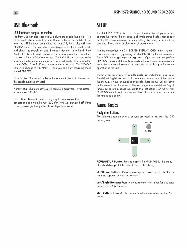
34 RSP-1572 SURROUND SOUND PROCESSOR
USB BluetoothUSB Bluetooth dongle connectionThe front USB can also accept a USB Bluetooth dongle (supplied). This allows you to stream music from your Bluetooth device, i.e. mobile phone. Insert the USB Bluetooth dongle into the front USB, the display will show “READY” status. From your device (mobile phone etc..) activate Bluetooth and allow it to search for other Bluetooth devices. It will find “Rotel Bluetooth”. Select “Rotel Bluetooth” and it may prompt you to enter a password. Enter “0000” and accept. The RSP-1572 will recognize that a device is attempting to connect to it, and will display this information on the OSD. Press ENT key on the remote to accept. The “READY” status will change to “RUNNING” and you can start streaming music to the RSP-1572.
Note: Not all Bluetooth dongles will operate with the unit. Please use the dongle supplied by Rotel.
Note: Not all Bluetooth devices will require a password. If requested for one enter “0000”.
Note: Some Bluetooth devices may require you to establish connection again with the RSP-1572 if the unit was powered off. If this occurs, please go through the above steps to re-connect
SETUPThe Rotel RSP-1572 features two types of information displays to help operate the system. The first consists of simple status displays that appear on the TV screen whenever primary settings (Volume, Input, etc.) are changed. These status displays are self-explanatory.
A more comprehensive ON-SCREEN DISPLAY (OSD) menu system is available at any time by pressing the RCVR/SETUP button on the remote. These OSD menus guide you through the configuration and setup of the RSP-1572. In general, the settings made in the configuration process are memorized as default settings and need not be made again for normal operation of the unit.
The OSD menus can be configured to display several different languages. The default English version of all main menus are shown at the front of this manual. If your language is available, those menus will be shown in the instructions. If you would like to change from the default English language before proceeding, go to the instructions for the OTHER OPTIONS menu later in this manual. From this menu, you can change the language display.
Menu BasicsNavigation Buttons The following remote control buttons are used to navigate the OSD menu system:
RCVR
SETUP
ENT
RCVR/SETUP button: Press to display the MAIN MENU. If a menu is already visible, push this button to cancel the display.
Up/Down Buttons: Press to move up and down in the lists of menu items that appear on the OSD screens.
Left/Right Buttons: Press to change the current settings for a selected menu item on OSD screens.
ENT Button: Press ENT to confirm a setting and return to the MAIN menu.
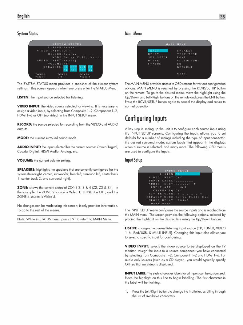
35English
System Status
S Y S T E M S T A T U S
L I S T E N : T u n e r
V I D E O I N P U T : O f f
R E C O R D : S o u r c e
M O D E : D o l b y P L I I x M u s i c
A U D I O I N P U T : A n a l o g
V O L U M E : 4 5
S P E A K E R S : F L C N T S U B F R
S L C B 1 C B 2 S R
V i d e o 1 O f f V i d e o 5Z O N E 2 : Z O N E 3 : Z O N E 4 :
The SYSTEM STATUS menu provides a snapshot of the current system settings. This screen appears when you press enter the STATUS Menu.
LISTEN: the input source selected for listening.
VIDEO INPUT: the video source selected for viewing. It is necessary to assign a video input, by selecting from Composite 1–2, Component 1–2, HDMI 1–6 or OFF (no video) in the INPUT SETUP menu.
RECORD: the source selected for recording from the VIDEO and AUDIO outputs.
MODE: the current surround sound mode.
AUDIO INPUT: the input selected for the current source: Optical Digital, Coaxial Digital, HDMI Audio, Analog, etc.
VOLUME: the current volume setting.
SPEAKERS: highlights the speakers that are currently configured for the system (front right, center, subwoofer, front left, surround left, center back 1, center back 2, and surround right).
ZONE: shows the current status of ZONE 2, 3 & 4 (Z2, Z3 & Z4). In the example, the ZONE 2 source is Video 1, ZONE 3 is OFF, and the ZONE 4 source is Video 5.
No changes can be made using this screen; it only provides information. To go to the rest of the menus.
Note: While in STATUS menu, press ENT to return to MAIN Menu.
Main Menu
M A I N M E N U
I N P U T S P E A K E R
D E L A Y T E S T T O N E
S U B S E T U P Z O N
O T H E R V I D E O / H D M I
S T A T U S E Q
D E F A U L T
E X I T
E
The MAIN MENU provides access to OSD screens for various configuration options. MAIN MENU is reached by pressing the RCVR/SETUP button on the remote. To go to the desired menu, move the highlight using the Up/Down and Left/Right buttons on the remote and press the ENT button. Press the RCVR/SETUP button again to cancel the display and return to normal operation.
Configuring InputsA key step in setting up the unit is to configure each source input using the INPUT SETUP screens. Configuring the inputs allows you to set defaults for a number of settings including the type of input connector, the desired surround mode, custom labels that appear in the displays when a source is selected, and many more. The following OSD menus are used to configure the inputs.
Input Setup
I N P U T S E T U P
L I S T E N : C D
V I D E O I N P U T : O f f
I N P U T L A B E L : _ _ _ _ _ _ _ _
A U D I O I N P U T : C o a x i a l 2
I N P U T A T T . : 0 d B
C I N E M A E Q : O f f
1 2 V T R I G G E R : 1 _ _ _ _ 6
D E F A U L T M O D E : D o l b y P L I I x M u s
G R O U P D E L A Y : 2 0 0 m S
M A I N M E N U
The INPUT SETUP menu configures the source inputs and is reached from the MAIN menu. The screen provides the following options, selected by placing the highlight on the desired line using the Up/Down buttons:
LISTEN: changes the current listening input source (CD, TUNER, VIDEO 1–6, iPod/USB, & MULTI INPUT). Changing this input also allows you to select a specific input for configuring.
VIDEO INPUT: selects the video source to be displayed on the TV monitor. Assign the input to a source component you have connected by selecting from Composite 1–2, Component 1–2 and HDMI 1–6. For audio only sources (such as a CD player), you would typically specify OFF so that no video is displayed.
INPUT LABEL: The eight character labels for all inputs can be customized. Place the highlight on this line to begin labelling. The first character in the label will be flashing.
Press the Left/Right buttons to change the first letter, scrolling through 1. the list of available characters.
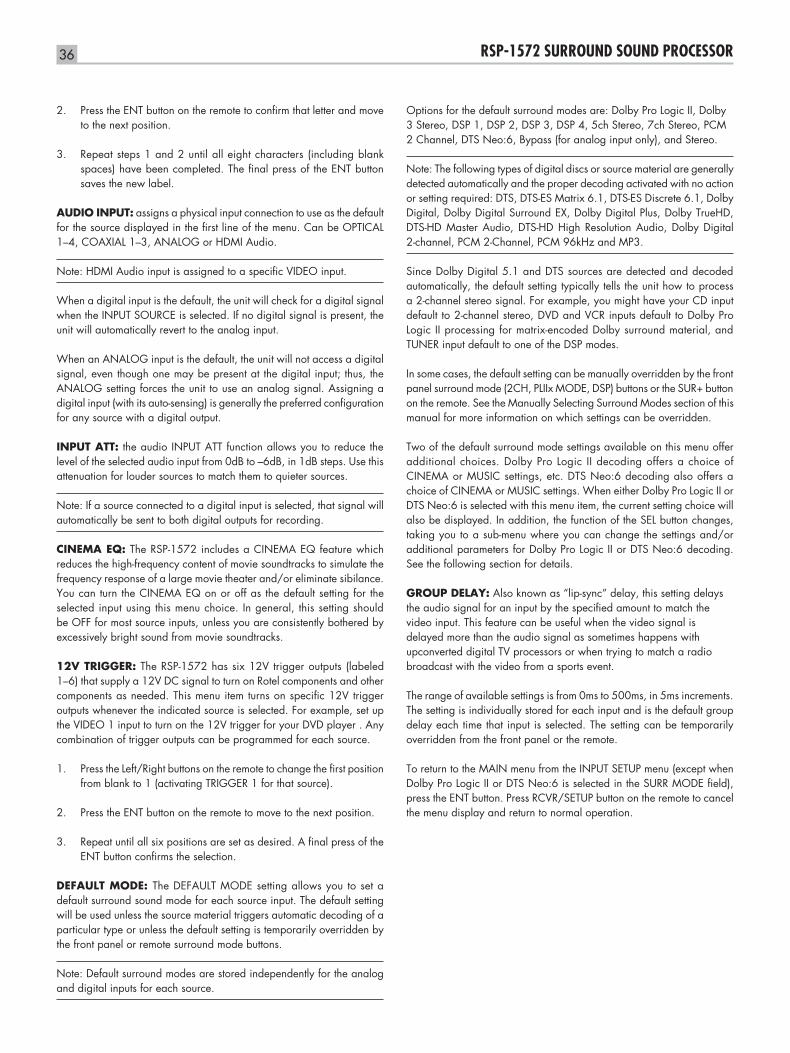
36 RSP-1572 SURROUND SOUND PROCESSOR
Press the ENT button on the remote to confirm that letter and move 2. to the next position.
Repeat steps 1 and 2 until all eight characters (including blank 3. spaces) have been completed. The final press of the ENT button saves the new label.
AUDIO INPUT: assigns a physical input connection to use as the default for the source displayed in the first line of the menu. Can be OPTICAL 1–4, COAXIAL 1–3, ANALOG or HDMI Audio.
Note: HDMI Audio input is assigned to a specific VIDEO input.
When a digital input is the default, the unit will check for a digital signal when the INPUT SOURCE is selected. If no digital signal is present, the unit will automatically revert to the analog input.
When an ANALOG input is the default, the unit will not access a digital signal, even though one may be present at the digital input; thus, the ANALOG setting forces the unit to use an analog signal. Assigning a digital input (with its auto-sensing) is generally the preferred configuration for any source with a digital output.
INPUT ATT: the audio INPUT ATT function allows you to reduce the level of the selected audio input from 0dB to –6dB, in 1dB steps. Use this attenuation for louder sources to match them to quieter sources.
Note: If a source connected to a digital input is selected, that signal will automatically be sent to both digital outputs for recording.
CINEMA EQ: The RSP-1572 includes a CINEMA EQ feature which reduces the high-frequency content of movie soundtracks to simulate the frequency response of a large movie theater and/or eliminate sibilance. You can turn the CINEMA EQ on or off as the default setting for the selected input using this menu choice. In general, this setting should be OFF for most source inputs, unless you are consistently bothered by excessively bright sound from movie soundtracks.
12V TRIGGER: The RSP-1572 has six 12V trigger outputs (labeled 1–6) that supply a 12V DC signal to turn on Rotel components and other components as needed. This menu item turns on specific 12V trigger outputs whenever the indicated source is selected. For example, set up the VIDEO 1 input to turn on the 12V trigger for your DVD player . Any combination of trigger outputs can be programmed for each source.
Press the Left/Right buttons on the remote to change the first position 1. from blank to 1 (activating TRIGGER 1 for that source).
Press the ENT button on the remote to move to the next position.2.
Repeat until all six positions are set as desired. A final press of the 3. ENT button confirms the selection.
DEFAULT MODE: The DEFAULT MODE setting allows you to set a default surround sound mode for each source input. The default setting will be used unless the source material triggers automatic decoding of a particular type or unless the default setting is temporarily overridden by the front panel or remote surround mode buttons.
Note: Default surround modes are stored independently for the analog and digital inputs for each source.
Options for the default surround modes are: Dolby Pro Logic II, Dolby 3 Stereo, DSP 1, DSP 2, DSP 3, DSP 4, 5ch Stereo, 7ch Stereo, PCM 2 Channel, DTS Neo:6, Bypass (for analog input only), and Stereo.
Note: The following types of digital discs or source material are generally detected automatically and the proper decoding activated with no action or setting required: DTS, DTS-ES Matrix 6.1, DTS-ES Discrete 6.1, Dolby Digital, Dolby Digital Surround EX, Dolby Digital Plus, Dolby TrueHD, DTS-HD Master Audio, DTS-HD High Resolution Audio, Dolby Digital 2-channel, PCM 2-Channel, PCM 96kHz and MP3.
Since Dolby Digital 5.1 and DTS sources are detected and decoded automatically, the default setting typically tells the unit how to process a 2-channel stereo signal. For example, you might have your CD input default to 2-channel stereo, DVD and VCR inputs default to Dolby Pro Logic II processing for matrix-encoded Dolby surround material, and TUNER input default to one of the DSP modes.
In some cases, the default setting can be manually overridden by the front panel surround mode (2CH, PLIIx MODE, DSP) buttons or the SUR+ button on the remote. See the Manually Selecting Surround Modes section of this manual for more information on which settings can be overridden.
Two of the default surround mode settings available on this menu offer additional choices. Dolby Pro Logic II decoding offers a choice of CINEMA or MUSIC settings, etc. DTS Neo:6 decoding also offers a choice of CINEMA or MUSIC settings. When either Dolby Pro Logic II or DTS Neo:6 is selected with this menu item, the current setting choice will also be displayed. In addition, the function of the SEL button changes, taking you to a sub-menu where you can change the settings and/or additional parameters for Dolby Pro Logic II or DTS Neo:6 decoding. See the following section for details.
GROUP DELAY: Also known as “lip-sync” delay, this setting delays the audio signal for an input by the specified amount to match the video input. This feature can be useful when the video signal is delayed more than the audio signal as sometimes happens with upconverted digital TV processors or when trying to match a radio broadcast with the video from a sports event.
The range of available settings is from 0ms to 500ms, in 5ms increments. The setting is individually stored for each input and is the default group delay each time that input is selected. The setting can be temporarily overridden from the front panel or the remote.
To return to the MAIN menu from the INPUT SETUP menu (except when Dolby Pro Logic II or DTS Neo:6 is selected in the SURR MODE field), press the ENT button. Press RCVR/SETUP button on the remote to cancel the menu display and return to normal operation.
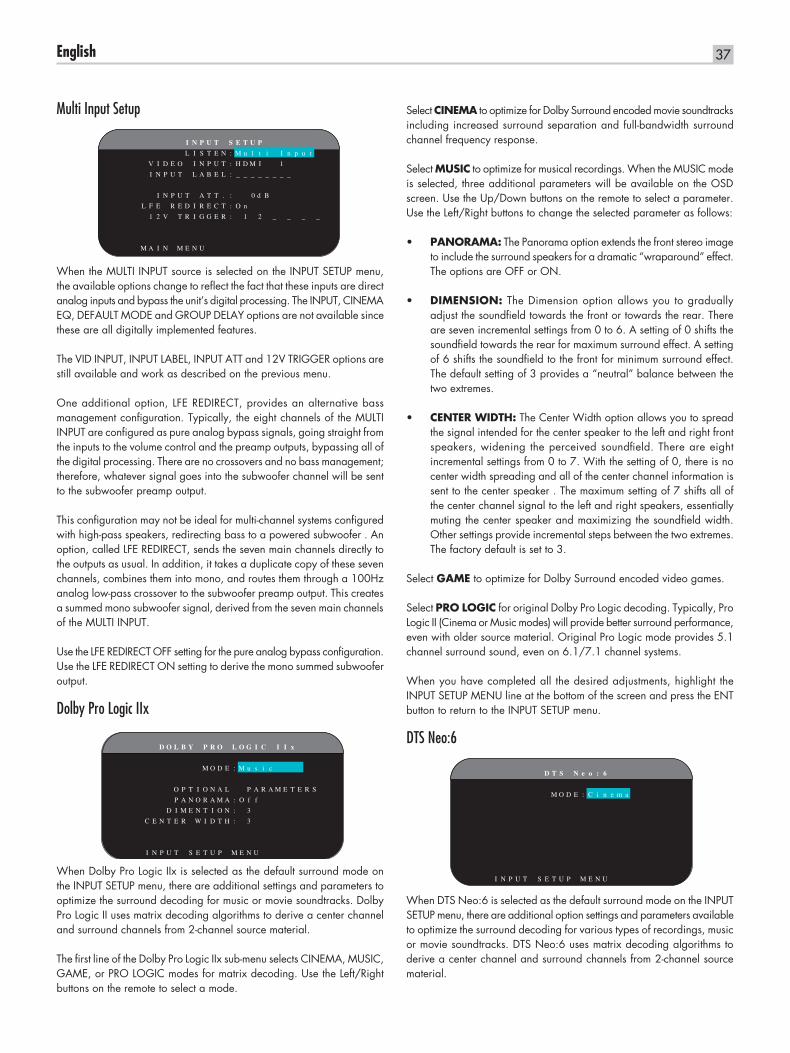
37English
Multi Input Setup
I N P U T S E T U P
L I S T E N : M u l t i I n p u t
V I D E O I N P U T : H D M I 1
I N P U T L A B E L : _ _ _ _ _ _ _ _
I N P U T A T T . : 0 d B
L F E R E D I R E C T : O n
1 2 V T R I G G E R : 1 2 _ _ _ _
M A I N M E N U
When the MULTI INPUT source is selected on the INPUT SETUP menu, the available options change to reflect the fact that these inputs are direct analog inputs and bypass the unit’s digital processing. The INPUT, CINEMA EQ, DEFAULT MODE and GROUP DELAY options are not available since these are all digitally implemented features.
The VID INPUT, INPUT LABEL, INPUT ATT and 12V TRIGGER options are still available and work as described on the previous menu.
One additional option, LFE REDIRECT, provides an alternative bass management configuration. Typically, the eight channels of the MULTI INPUT are configured as pure analog bypass signals, going straight from the inputs to the volume control and the preamp outputs, bypassing all of the digital processing. There are no crossovers and no bass management; therefore, whatever signal goes into the subwoofer channel will be sent to the subwoofer preamp output.
This configuration may not be ideal for multi-channel systems configured with high-pass speakers, redirecting bass to a powered subwoofer . An option, called LFE REDIRECT, sends the seven main channels directly to the outputs as usual. In addition, it takes a duplicate copy of these seven channels, combines them into mono, and routes them through a 100Hz analog low-pass crossover to the subwoofer preamp output. This creates a summed mono subwoofer signal, derived from the seven main channels of the MULTI INPUT.
Use the LFE REDIRECT OFF setting for the pure analog bypass configuration. Use the LFE REDIRECT ON setting to derive the mono summed subwoofer output.
Dolby Pro Logic IIx
D O L B Y P R O L O G I C I I x
M O D E : M u s i c
O P T I O N A L P A R A M E T E R S
P A N O R A M A : O f f
D I M E N T I O N : 3
C E N T E R W I D T H : 3
I N P U T S E T U P M E N U
When Dolby Pro Logic IIx is selected as the default surround mode on the INPUT SETUP menu, there are additional settings and parameters to optimize the surround decoding for music or movie soundtracks. Dolby Pro Logic II uses matrix decoding algorithms to derive a center channel and surround channels from 2-channel source material.
The first line of the Dolby Pro Logic IIx sub-menu selects CINEMA, MUSIC, GAME, or PRO LOGIC modes for matrix decoding. Use the Left/Right buttons on the remote to select a mode.
Select CINEMA to optimize for Dolby Surround encoded movie soundtracks including increased surround separation and full-bandwidth surround channel frequency response.
Select MUSIC to optimize for musical recordings. When the MUSIC mode is selected, three additional parameters will be available on the OSD screen. Use the Up/Down buttons on the remote to select a parameter. Use the Left/Right buttons to change the selected parameter as follows:
PANORAMA:• The Panorama option extends the front stereo image to include the surround speakers for a dramatic “wraparound” effect. The options are OFF or ON.
DIMENSION:• The Dimension option allows you to gradually adjust the soundfield towards the front or towards the rear. There are seven incremental settings from 0 to 6. A setting of 0 shifts the soundfield towards the rear for maximum surround effect. A setting of 6 shifts the soundfield to the front for minimum surround effect. The default setting of 3 provides a “neutral” balance between the two extremes.
CENTER WIDTH:• The Center Width option allows you to spread the signal intended for the center speaker to the left and right front speakers, widening the perceived soundfield. There are eight incremental settings from 0 to 7. With the setting of 0, there is no center width spreading and all of the center channel information is sent to the center speaker . The maximum setting of 7 shifts all of the center channel signal to the left and right speakers, essentially muting the center speaker and maximizing the soundfield width. Other settings provide incremental steps between the two extremes. The factory default is set to 3.
Select GAME to optimize for Dolby Surround encoded video games.
Select PRO LOGIC for original Dolby Pro Logic decoding. Typically, Pro Logic II (Cinema or Music modes) will provide better surround performance, even with older source material. Original Pro Logic mode provides 5.1 channel surround sound, even on 6.1/7.1 channel systems.
When you have completed all the desired adjustments, highlight the INPUT SETUP MENU line at the bottom of the screen and press the ENT button to return to the INPUT SETUP menu.
DTS Neo:6
D T S N e o : 6
M O D E : C i n e m a
I N P U T S E T U P M E N U
When DTS Neo:6 is selected as the default surround mode on the INPUT SETUP menu, there are additional option settings and parameters available to optimize the surround decoding for various types of recordings, music or movie soundtracks. DTS Neo:6 uses matrix decoding algorithms to derive a center channel and surround channels from 2-channel source material.
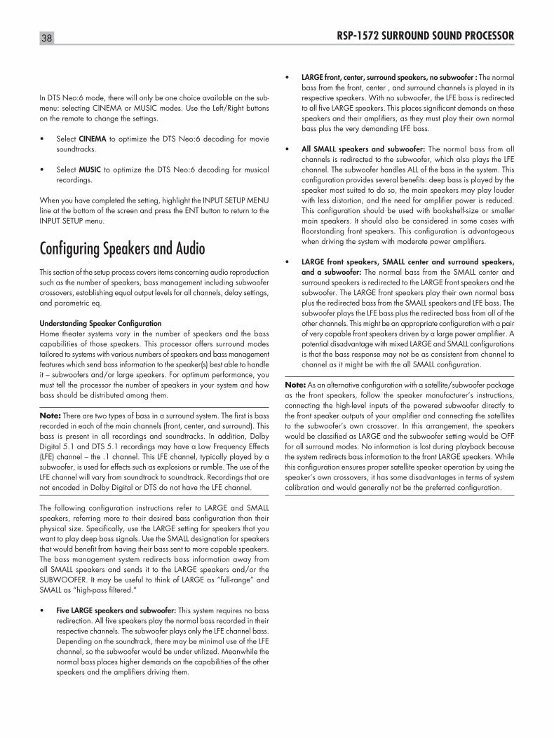
38 RSP-1572 SURROUND SOUND PROCESSOR
In DTS Neo:6 mode, there will only be one choice available on the sub-menu: selecting CINEMA or MUSIC modes. Use the Left/Right buttons on the remote to change the settings.
Select • CINEMA to optimize the DTS Neo:6 decoding for movie soundtracks.
Select • MUSIC to optimize the DTS Neo:6 decoding for musical recordings.
When you have completed the setting, highlight the INPUT SETUP MENU line at the bottom of the screen and press the ENT button to return to the INPUT SETUP menu.
Configuring Speakers and AudioThis section of the setup process covers items concerning audio reproduction such as the number of speakers, bass management including subwoofer crossovers, establishing equal output levels for all channels, delay settings, and parametric eq.
Understanding Speaker ConfigurationHome theater systems vary in the number of speakers and the bass capabilities of those speakers. This processor offers surround modes tailored to systems with various numbers of speakers and bass management features which send bass information to the speaker(s) best able to handle it – subwoofers and/or large speakers. For optimum performance, you must tell the processor the number of speakers in your system and how bass should be distributed among them.
Note: There are two types of bass in a surround system. The first is bass recorded in each of the main channels (front, center, and surround). This bass is present in all recordings and soundtracks. In addition, Dolby Digital 5.1 and DTS 5.1 recordings may have a Low Frequency Effects (LFE) channel – the .1 channel. This LFE channel, typically played by a subwoofer, is used for effects such as explosions or rumble. The use of the LFE channel will vary from soundtrack to soundtrack. Recordings that are not encoded in Dolby Digital or DTS do not have the LFE channel.
The following configuration instructions refer to LARGE and SMALL speakers, referring more to their desired bass configuration than their physical size. Specifically, use the LARGE setting for speakers that you want to play deep bass signals. Use the SMALL designation for speakers that would benefit from having their bass sent to more capable speakers. The bass management system redirects bass information away from all SMALL speakers and sends it to the LARGE speakers and/or the SUBWOOFER. It may be useful to think of LARGE as “full-range” and SMALL as “high-pass filtered.”
Five LARGE speakers and subwoofer:• This system requires no bass redirection. All five speakers play the normal bass recorded in their respective channels. The subwoofer plays only the LFE channel bass. Depending on the soundtrack, there may be minimal use of the LFE channel, so the subwoofer would be under utilized. Meanwhile the normal bass places higher demands on the capabilities of the other speakers and the amplifiers driving them.
LARGE front, center, surround speakers, no subwoofer :• The normal bass from the front, center , and surround channels is played in its respective speakers. With no subwoofer, the LFE bass is redirected to all five LARGE speakers. This places significant demands on these speakers and their amplifiers, as they must play their own normal bass plus the very demanding LFE bass.
All SMALL speakers and subwoofer:• The normal bass from all channels is redirected to the subwoofer, which also plays the LFE channel. The subwoofer handles ALL of the bass in the system. This configuration provides several benefits: deep bass is played by the speaker most suited to do so, the main speakers may play louder with less distortion, and the need for amplifier power is reduced. This configuration should be used with bookshelf-size or smaller main speakers. It should also be considered in some cases with floorstanding front speakers. This configuration is advantageous when driving the system with moderate power amplifiers.
LARGE front speakers, SMALL center and surround speakers, •and a subwoofer: The normal bass from the SMALL center and surround speakers is redirected to the LARGE front speakers and the subwoofer. The LARGE front speakers play their own normal bass plus the redirected bass from the SMALL speakers and LFE bass. The subwoofer plays the LFE bass plus the redirected bass from all of the other channels. This might be an appropriate configuration with a pair of very capable front speakers driven by a large power amplifier. A potential disadvantage with mixed LARGE and SMALL configurations is that the bass response may not be as consistent from channel to channel as it might be with the all SMALL configuration.
Note: As an alternative configuration with a satellite/subwoofer package as the front speakers, follow the speaker manufacturer’s instructions, connecting the high-level inputs of the powered subwoofer directly to the front speaker outputs of your amplifier and connecting the satellites to the subwoofer’s own crossover. In this arrangement, the speakers would be classified as LARGE and the subwoofer setting would be OFF for all surround modes. No information is lost during playback because the system redirects bass information to the front LARGE speakers. While this configuration ensures proper satellite speaker operation by using the speaker’s own crossovers, it has some disadvantages in terms of system calibration and would generally not be the preferred configuration.
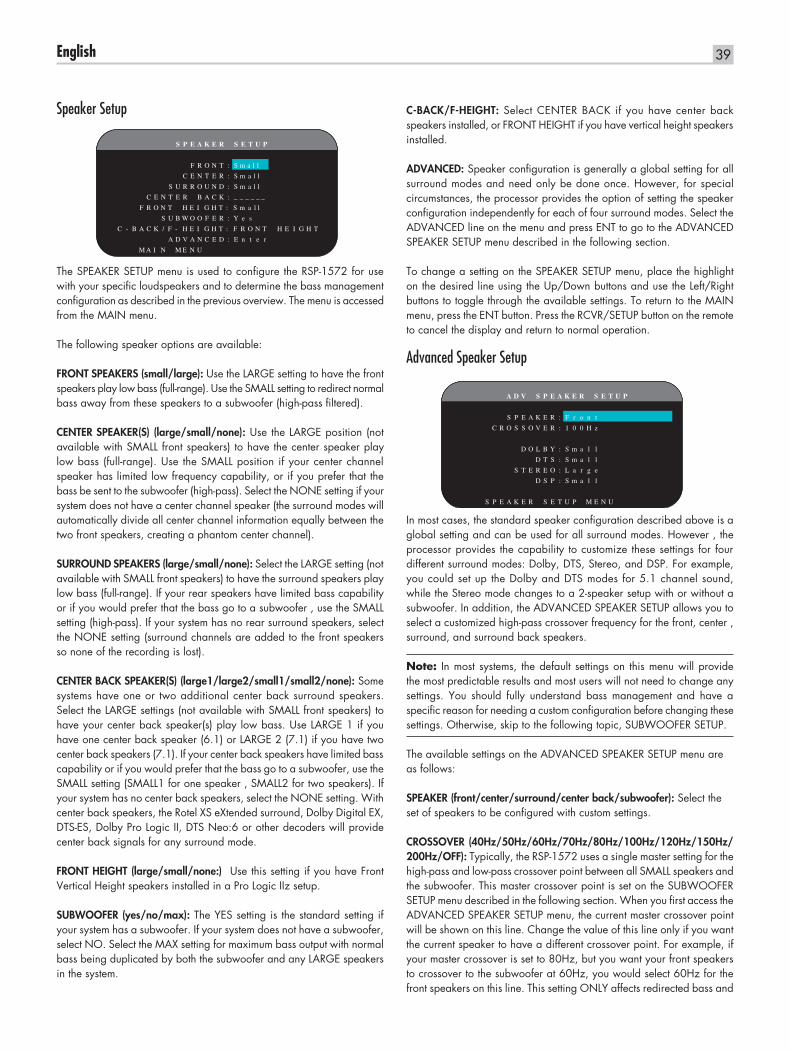
39English
Speaker Setup
S P E A K E R S E T U P
F R O N T : S m a l l
C E N T E R : S m a l l
S U R R O U N D : S m a l l
C E N T E R B A C K : _ _ _ _ _ _
F R O N T H E I G H T : S m a l l
S U B W O O F E R : Y e s
C - B A C K / F - H E I G H T : F R O N T H E I G H T
A D V A N C E D : E n t e r
M A I N M E N U
The SPEAKER SETUP menu is used to configure the RSP-1572 for use with your specific loudspeakers and to determine the bass management configuration as described in the previous overview. The menu is accessed from the MAIN menu.
The following speaker options are available:
FRONT SPEAKERS (small/large): Use the LARGE setting to have the front speakers play low bass (full-range). Use the SMALL setting to redirect normal bass away from these speakers to a subwoofer (high-pass filtered).
CENTER SPEAKER(S) (large/small/none): Use the LARGE position (not available with SMALL front speakers) to have the center speaker play low bass (full-range). Use the SMALL position if your center channel speaker has limited low frequency capability, or if you prefer that the bass be sent to the subwoofer (high-pass). Select the NONE setting if your system does not have a center channel speaker (the surround modes will automatically divide all center channel information equally between the two front speakers, creating a phantom center channel).
SURROUND SPEAKERS (large/small/none): Select the LARGE setting (not available with SMALL front speakers) to have the surround speakers play low bass (full-range). If your rear speakers have limited bass capability or if you would prefer that the bass go to a subwoofer , use the SMALL setting (high-pass). If your system has no rear surround speakers, select the NONE setting (surround channels are added to the front speakers so none of the recording is lost).
CENTER BACK SPEAKER(S) (large1/large2/small1/small2/none): Some systems have one or two additional center back surround speakers. Select the LARGE settings (not available with SMALL front speakers) to have your center back speaker(s) play low bass. Use LARGE 1 if you have one center back speaker (6.1) or LARGE 2 (7.1) if you have two center back speakers (7.1). If your center back speakers have limited bass capability or if you would prefer that the bass go to a subwoofer, use the SMALL setting (SMALL1 for one speaker , SMALL2 for two speakers). If your system has no center back speakers, select the NONE setting. With center back speakers, the Rotel XS eXtended surround, Dolby Digital EX, DTS-ES, Dolby Pro Logic II, DTS Neo:6 or other decoders will provide center back signals for any surround mode.
FRONT HEIGHT (large/small/none:) Use this setting if you have Front Vertical Height speakers installed in a Pro Logic IIz setup.
SUBWOOFER (yes/no/max): The YES setting is the standard setting if your system has a subwoofer. If your system does not have a subwoofer, select NO. Select the MAX setting for maximum bass output with normal bass being duplicated by both the subwoofer and any LARGE speakers in the system.
C-BACK/F-HEIGHT: Select CENTER BACK if you have center back speakers installed, or FRONT HEIGHT if you have vertical height speakers installed.
ADVANCED: Speaker configuration is generally a global setting for all surround modes and need only be done once. However, for special circumstances, the processor provides the option of setting the speaker configuration independently for each of four surround modes. Select the ADVANCED line on the menu and press ENT to go to the ADVANCED SPEAKER SETUP menu described in the following section.
To change a setting on the SPEAKER SETUP menu, place the highlight on the desired line using the Up/Down buttons and use the Left/Right buttons to toggle through the available settings. To return to the MAIN menu, press the ENT button. Press the RCVR/SETUP button on the remote to cancel the display and return to normal operation.
Advanced Speaker Setup
A D V S P E A K E R S E T U P
S P E A K E R : F r o n t
C R O S S O V E R : 1 0 0 H z
D O L B Y : S m a l l
D T S : S m a l l
S T E R E O : L a r g e
D S P : S m a l l
S P E A K E R S E T U P M E N U
In most cases, the standard speaker configuration described above is a global setting and can be used for all surround modes. However , the processor provides the capability to customize these settings for four different surround modes: Dolby, DTS, Stereo, and DSP. For example, you could set up the Dolby and DTS modes for 5.1 channel sound, while the Stereo mode changes to a 2-speaker setup with or without a subwoofer. In addition, the ADVANCED SPEAKER SETUP allows you to select a customized high-pass crossover frequency for the front, center , surround, and surround back speakers.
Note: In most systems, the default settings on this menu will provide the most predictable results and most users will not need to change any settings. You should fully understand bass management and have a specific reason for needing a custom configuration before changing these settings. Otherwise, skip to the following topic, SUBWOOFER SETUP.
The available settings on the ADVANCED SPEAKER SETUP menu are as follows:
SPEAKER (front/center/surround/center back/subwoofer): Select the set of speakers to be configured with custom settings.
CROSSOVER (40Hz/50Hz/60Hz/70Hz/80Hz/100Hz/120Hz/150Hz/ 200Hz/OFF): Typically, the RSP-1572 uses a single master setting for the high-pass and low-pass crossover point between all SMALL speakers and the subwoofer. This master crossover point is set on the SUBWOOFER SETUP menu described in the following section. When you first access the ADVANCED SPEAKER SETUP menu, the current master crossover point will be shown on this line. Change the value of this line only if you want the current speaker to have a different crossover point. For example, if your master crossover is set to 80Hz, but you want your front speakers to crossover to the subwoofer at 60Hz, you would select 60Hz for the front speakers on this line. This setting ONLY affects redirected bass and
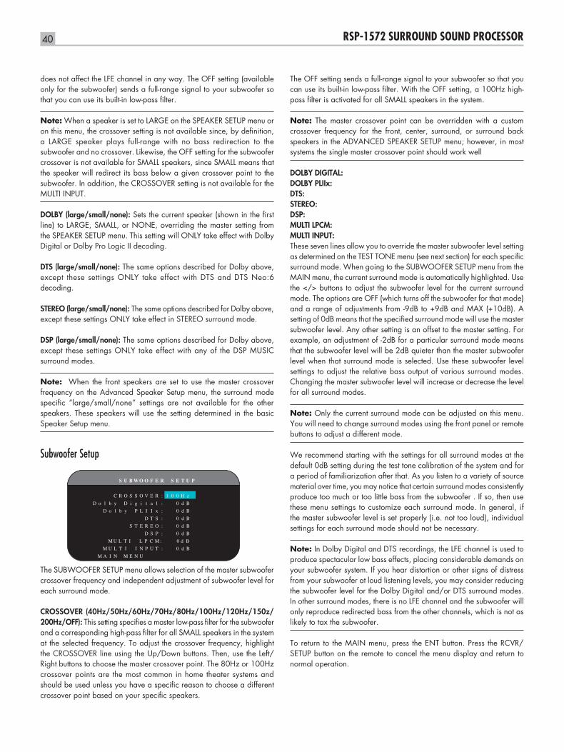
40 RSP-1572 SURROUND SOUND PROCESSOR
does not affect the LFE channel in any way. The OFF setting (available only for the subwoofer) sends a full-range signal to your subwoofer so that you can use its built-in low-pass filter.
Note: When a speaker is set to LARGE on the SPEAKER SETUP menu or on this menu, the crossover setting is not available since, by definition, a LARGE speaker plays full-range with no bass redirection to the subwoofer and no crossover. Likewise, the OFF setting for the subwoofer crossover is not available for SMALL speakers, since SMALL means that the speaker will redirect its bass below a given crossover point to the subwoofer. In addition, the CROSSOVER setting is not available for the MULTI INPUT.
DOLBY (large/small/none): Sets the current speaker (shown in the first line) to LARGE, SMALL, or NONE, overriding the master setting from the SPEAKER SETUP menu. This setting will ONLY take effect with Dolby Digital or Dolby Pro Logic II decoding.
DTS (large/small/none): The same options described for Dolby above, except these settings ONLY take effect with DTS and DTS Neo:6 decoding.
STEREO (large/small/none): The same options described for Dolby above, except these settings ONLY take effect in STEREO surround mode.
DSP (large/small/none): The same options described for Dolby above, except these settings ONLY take effect with any of the DSP MUSIC surround modes.
Note: When the front speakers are set to use the master crossover frequency on the Advanced Speaker Setup menu, the surround mode specific “large/small/none” settings are not available for the other speakers. These speakers will use the setting determined in the basic Speaker Setup menu.
Subwoofer Setup
S U B W O O F E R S E T U P
C R O S S O V E R : 1 0 0 H z
D o l b y D i g i t a l : 0 d B
D o l b y P L I I x : 0 d B
D T S : 0 d B
S T E R E O : 0 d B
D S P : 0 d B
M U L T I L P C M : 0 d B
M U L T I I N P U T : 0 d B
M A I N M E N U
The SUBWOOFER SETUP menu allows selection of the master subwoofer crossover frequency and independent adjustment of subwoofer level for each surround mode.
CROSSOVER (40Hz/50Hz/60Hz/70Hz/80Hz/100Hz/120Hz/150z/ 200Hz/OFF): This setting specifies a master low-pass filter for the subwoofer and a corresponding high-pass filter for all SMALL speakers in the system at the selected frequency. To adjust the crossover frequency, highlight the CROSSOVER line using the Up/Down buttons. Then, use the Left/Right buttons to choose the master crossover point. The 80Hz or 100Hz crossover points are the most common in home theater systems and should be used unless you have a specific reason to choose a different crossover point based on your specific speakers.
The OFF setting sends a full-range signal to your subwoofer so that you can use its built-in low-pass filter. With the OFF setting, a 100Hz high-pass filter is activated for all SMALL speakers in the system.
Note: The master crossover point can be overridden with a custom crossover frequency for the front, center, surround, or surround back speakers in the ADVANCED SPEAKER SETUP menu; however, in most systems the single master crossover point should work well
DOLBY DIGITAL: DOLBY PLIIx: DTS: STEREO: DSP: MULTI LPCM:MULTI INPUT: These seven lines allow you to override the master subwoofer level setting as determined on the TEST TONE menu (see next section) for each specific surround mode. When going to the SUBWOOFER SETUP menu from the MAIN menu, the current surround mode is automatically highlighted. Use the </> buttons to adjust the subwoofer level for the current surround mode. The options are OFF (which turns off the subwoofer for that mode) and a range of adjustments from -9dB to +9dB and MAX (+10dB). A setting of 0dB means that the specified surround mode will use the master subwoofer level. Any other setting is an offset to the master setting. For example, an adjustment of -2dB for a particular surround mode means that the subwoofer level will be 2dB quieter than the master subwoofer level when that surround mode is selected. Use these subwoofer level settings to adjust the relative bass output of various surround modes. Changing the master subwoofer level will increase or decrease the level for all surround modes.
Note: Only the current surround mode can be adjusted on this menu. You will need to change surround modes using the front panel or remote buttons to adjust a different mode.
We recommend starting with the settings for all surround modes at the default 0dB setting during the test tone calibration of the system and for a period of familiarization after that. As you listen to a variety of source material over time, you may notice that certain surround modes consistently produce too much or too little bass from the subwoofer . If so, then use these menu settings to customize each surround mode. In general, if the master subwoofer level is set properly (i.e. not too loud), individual settings for each surround mode should not be necessary.
Note: In Dolby Digital and DTS recordings, the LFE channel is used to produce spectacular low bass effects, placing considerable demands on your subwoofer system. If you hear distortion or other signs of distress from your subwoofer at loud listening levels, you may consider reducing the subwoofer level for the Dolby Digital and/or DTS surround modes. In other surround modes, there is no LFE channel and the subwoofer will only reproduce redirected bass from the other channels, which is not as likely to tax the subwoofer.
To return to the MAIN menu, press the ENT button. Press the RCVR/SETUP button on the remote to cancel the menu display and return to normal operation.
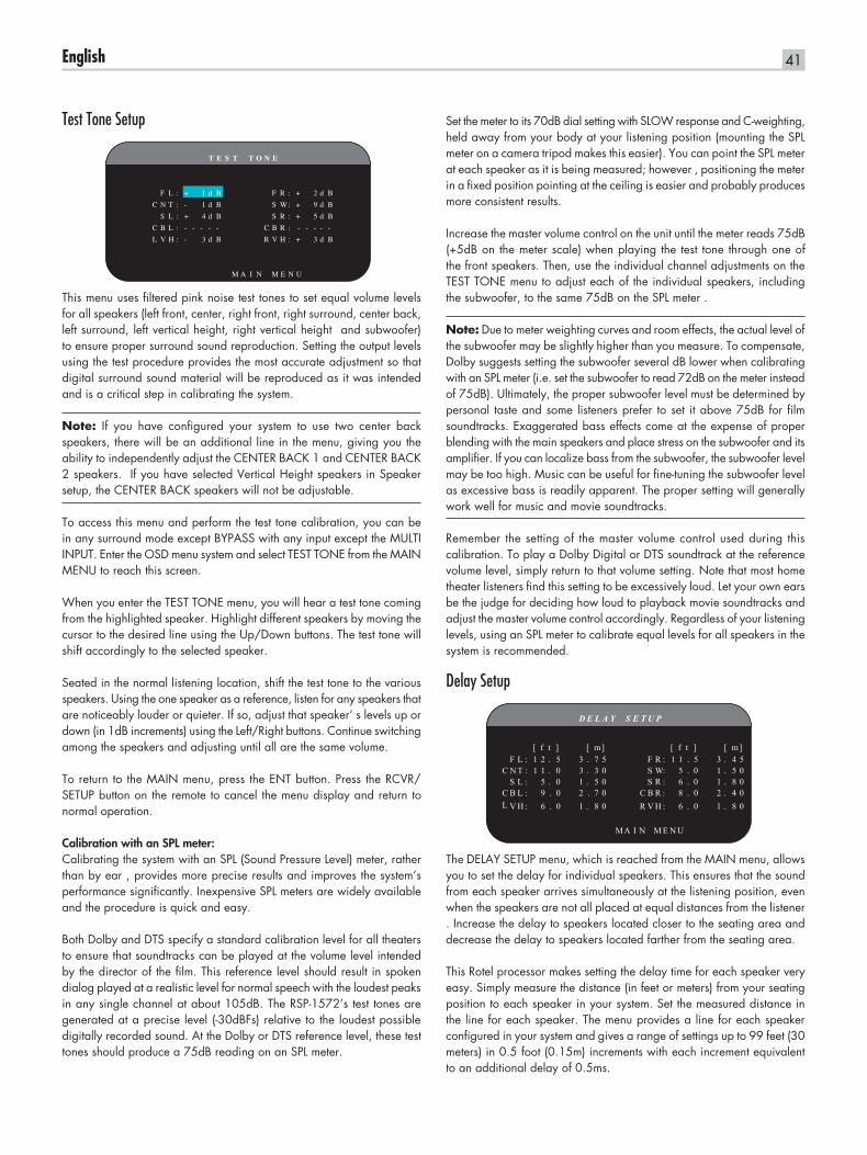
41English
Test Tone Setup
T E S T T O N E
F L : + 1 d B F R : + 2 d B
C N T : - 1 d B S W: + 9 d B
S L : + 4 d B S R : + 5 d B
C B L : - - - - - C B R : - - - - -
L V H : - 3 d B R V H : + 3 d B
M A I N M E N U
This menu uses filtered pink noise test tones to set equal volume levels for all speakers (left front, center, right front, right surround, center back, left surround, left vertical height, right vertical height and subwoofer) to ensure proper surround sound reproduction. Setting the output levels using the test procedure provides the most accurate adjustment so that digital surround sound material will be reproduced as it was intended and is a critical step in calibrating the system.
Note: If you have configured your system to use two center back speakers, there will be an additional line in the menu, giving you the ability to independently adjust the CENTER BACK 1 and CENTER BACK 2 speakers. If you have selected Vertical Height speakers in Speaker setup, the CENTER BACK speakers will not be adjustable.
To access this menu and perform the test tone calibration, you can be in any surround mode except BYPASS with any input except the MULTI INPUT. Enter the OSD menu system and select TEST TONE from the MAIN MENU to reach this screen.
When you enter the TEST TONE menu, you will hear a test tone coming from the highlighted speaker. Highlight different speakers by moving the cursor to the desired line using the Up/Down buttons. The test tone will shift accordingly to the selected speaker.
Seated in the normal listening location, shift the test tone to the various speakers. Using the one speaker as a reference, listen for any speakers that are noticeably louder or quieter. If so, adjust that speaker’ s levels up or down (in 1dB increments) using the Left/Right buttons. Continue switching among the speakers and adjusting until all are the same volume.
To return to the MAIN menu, press the ENT button. Press the RCVR/SETUP button on the remote to cancel the menu display and return to normal operation.
Calibration with an SPL meter:Calibrating the system with an SPL (Sound Pressure Level) meter, rather than by ear , provides more precise results and improves the system’s performance significantly. Inexpensive SPL meters are widely available and the procedure is quick and easy.
Both Dolby and DTS specify a standard calibration level for all theaters to ensure that soundtracks can be played at the volume level intended by the director of the film. This reference level should result in spoken dialog played at a realistic level for normal speech with the loudest peaks in any single channel at about 105dB. The RSP-1572’s test tones are generated at a precise level (-30dBFs) relative to the loudest possible digitally recorded sound. At the Dolby or DTS reference level, these test tones should produce a 75dB reading on an SPL meter.
Set the meter to its 70dB dial setting with SLOW response and C-weighting, held away from your body at your listening position (mounting the SPL meter on a camera tripod makes this easier). You can point the SPL meter at each speaker as it is being measured; however , positioning the meter in a fixed position pointing at the ceiling is easier and probably produces more consistent results.
Increase the master volume control on the unit until the meter reads 75dB (+5dB on the meter scale) when playing the test tone through one of the front speakers. Then, use the individual channel adjustments on the TEST TONE menu to adjust each of the individual speakers, including the subwoofer, to the same 75dB on the SPL meter .
Note: Due to meter weighting curves and room effects, the actual level of the subwoofer may be slightly higher than you measure. To compensate, Dolby suggests setting the subwoofer several dB lower when calibrating with an SPL meter (i.e. set the subwoofer to read 72dB on the meter instead of 75dB). Ultimately, the proper subwoofer level must be determined by personal taste and some listeners prefer to set it above 75dB for film soundtracks. Exaggerated bass effects come at the expense of proper blending with the main speakers and place stress on the subwoofer and its amplifier. If you can localize bass from the subwoofer, the subwoofer level may be too high. Music can be useful for fine-tuning the subwoofer level as excessive bass is readily apparent. The proper setting will generally work well for music and movie soundtracks.
Remember the setting of the master volume control used during this calibration. To play a Dolby Digital or DTS soundtrack at the reference volume level, simply return to that volume setting. Note that most home theater listeners find this setting to be excessively loud. Let your own ears be the judge for deciding how loud to playback movie soundtracks and adjust the master volume control accordingly. Regardless of your listening levels, using an SPL meter to calibrate equal levels for all speakers in the system is recommended.
Delay Setup
D E L A Y S E T U P
[ f t ] [ m] [ f t ] [ m]F L : 1 2 . 5 3 . 7 5 F R : 1 1 . 5 3 . 4 5
C N T : 1 1 . 0 3 . 3 0 S W: 5 . 0 1 . 5 0S L : 5 . 0 1 . 5 0 S R : 6 . 0 1 . 8 0
C B L : 9 . 0 2 . 7 0 C B R : 8 . 0 2 . 4 0L V H : 6 . 0 1 . 8 0 R V H : 6 . 0 1 . 8 0
MA I N M E N U
The DELAY SETUP menu, which is reached from the MAIN menu, allows you to set the delay for individual speakers. This ensures that the sound from each speaker arrives simultaneously at the listening position, even when the speakers are not all placed at equal distances from the listener . Increase the delay to speakers located closer to the seating area and decrease the delay to speakers located farther from the seating area.
This Rotel processor makes setting the delay time for each speaker very easy. Simply measure the distance (in feet or meters) from your seating position to each speaker in your system. Set the measured distance in the line for each speaker. The menu provides a line for each speaker configured in your system and gives a range of settings up to 99 feet (30 meters) in 0.5 foot (0.15m) increments with each increment equivalent to an additional delay of 0.5ms.
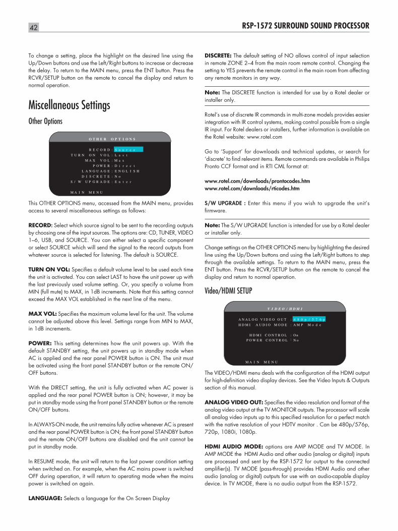
42 RSP-1572 SURROUND SOUND PROCESSOR
To change a setting, place the highlight on the desired line using the Up/Down buttons and use the Left/Right buttons to increase or decrease the delay. To return to the MAIN menu, press the ENT button. Press the RCVR/SETUP button on the remote to cancel the display and return to normal operation.
Miscellaneous SettingsOther Options
O T H E R O P T I O N S
R E C O R D : S o u r c e
T U R N O N V O L : L a s t
M A X V O L : M a x
P O W E R : D i r e c t
L A N G U A G E : E N G L I S H
D I S C R E T E : N o
S / W U P G R A D E : E n t e r
M A I N M E N U
This OTHER OPTIONS menu, accessed from the MAIN menu, provides access to several miscellaneous settings as follows:
RECORD: Select which source signal to be sent to the recording outputs by choosing one of the input sources. The options are: CD, TUNER, VIDEO 1–6, USB, and SOURCE. You can either select a specific component or select SOURCE which will send the signal to the record outputs from whatever source is selected for listening. The default is SOURCE.
TURN ON VOL: Specifies a default volume level to be used each time the unit is activated. You can select LAST to have the unit power up with the last previously used volume setting. Or, you specify a volume from MIN (full mute) to MAX, in 1dB increments. Note that this setting cannot exceed the MAX VOL established in the next line of the menu.
MAX VOL: Specifies the maximum volume level for the unit. The volume cannot be adjusted above this level. Settings range from MIN to MAX, in 1dB increments.
POWER: This setting determines how the unit powers up. With the default STANDBY setting, the unit powers up in standby mode when AC is applied and the rear panel POWER button is ON. The unit must be activated using the front panel STANDBY button or the remote ON/OFF buttons.
With the DIRECT setting, the unit is fully activated when AC power is applied and the rear panel POWER button is ON; however, it may be put in standby mode using the front panel STANDBY button or the remote ON/OFF buttons.
In ALWAYS-ON mode, the unit remains fully active whenever AC is present and the rear panel POWER button is ON; the front panel STANDBY button and the remote ON/OFF buttons are disabled and the unit cannot be put in standby mode.
In RESUME mode, the unit will return to the last power condition setting when switched on. For example, when the AC mains power is switched OFF during operation, it will return to operating mode when the mains power is switched on again.
LANGUAGE: Selects a language for the On Screen Display
DISCRETE: The default setting of NO allows control of input selection in remote ZONE 2–4 from the main room remote control. Changing the setting to YES prevents the remote control in the main room from affecting any remote monitors in any way.
Note: The DISCRETE function is intended for use by a Rotel dealer or installer only.
Rotel’s use of discrete IR commands in multi-zone models provides easier integration with IR control systems, making control possible from a single IR input. For Rotel dealers or installers, further information is available on the Rotel website: www.rotel.com
Go to ‘Support’ for downloads and technical updates, or search for ‘discrete’ to find relevant items. Remote commands are available in Philips Pronto CCF format and in RTI CML format at:
www.rotel.com/downloads/prontocodes.htm www.rotel.com/downloads/rticodes.htm
S/W UPGRADE : Enter this menu if you wish to upgrade the unit’s firmware.
Note: The S/W UPGRADE function is intended for use by a Rotel dealer or installer only.
Change settings on the OTHER OPTIONS menu by highlighting the desired line using the Up/Down buttons and using the Left/Right buttons to step through the available settings. To return to the MAIN menu, press the ENT button. Press the RCVR/SETUP button on the remote to cancel the display and return to normal operation.
Video/HDMI SETUP
V I D E O / H D M I
A N A L O G V I D E O O U T : 4 8 0 p / 5 7 6 p
H D M I A U D I O M O D E : A M P M o d e
H D M I C O N T R O L : O n
M A I N M E N U
P O W E R C O N T R O L : N o
The VIDEO/HDMI menu deals with the configuration of the HDMI output for high-definition video display devices. See the Video Inputs & Outputs section of this manual.
ANALOG VIDEO OUT: Specifies the video resolution and format of the analog video output at the TV MONITOR outputs. The processor will scale all analog video inputs up to this specified resolution for a perfect match with the native resolution of your HDTV monitor . Can be 480p/576p, 720p, 1080i, 1080p.
HDMI AUDIO MODE: options are AMP MODE and TV MODE. In AMP MODE the HDMI Audio and other audio (analog or digital) inputs are processed and sent by the RSP-1572 for output to the connected amplifier(s). TV MODE (pass-through) provides HDMI Audio and other audio (analog or digital) outputs for use with an audio-capable display device. In TV MODE, there is no audio output from the RSP-1572.
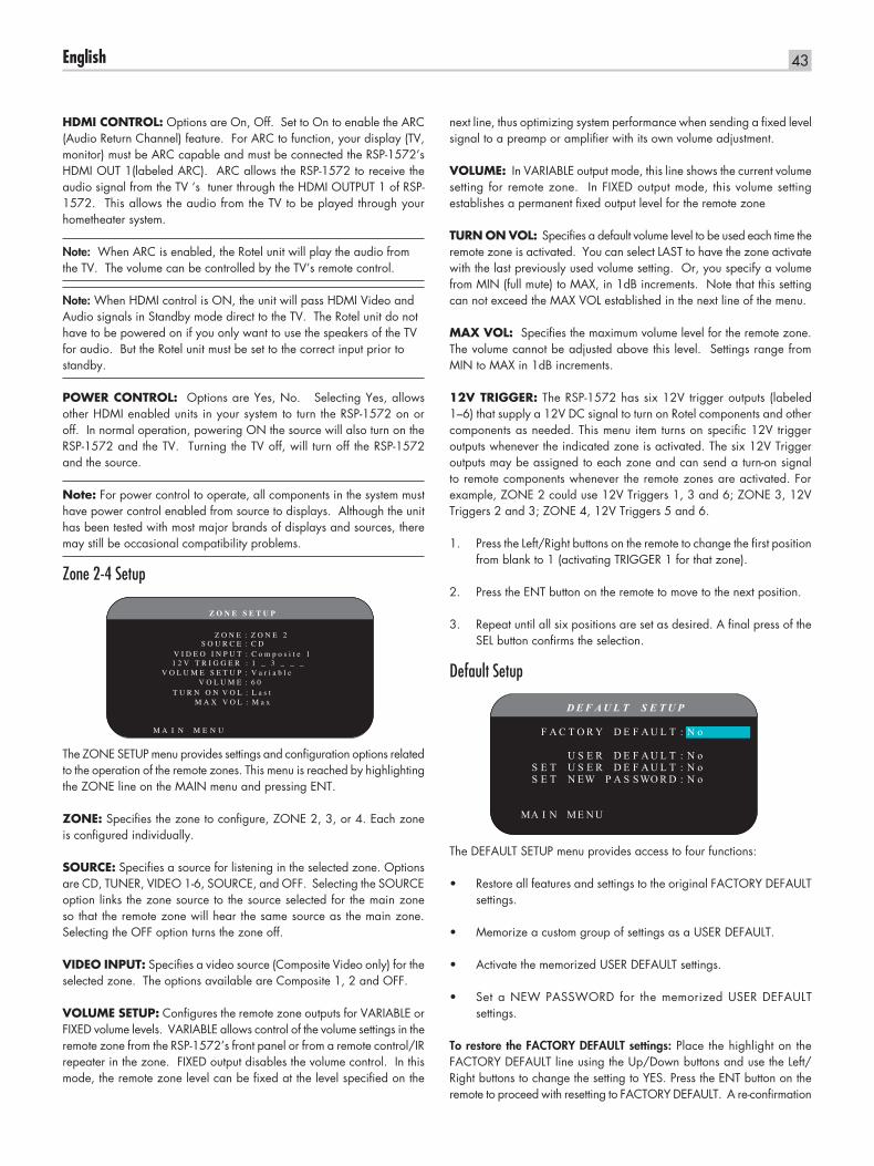
43English
next line, thus optimizing system performance when sending a fixed level signal to a preamp or amplifier with its own volume adjustment.
VOLUME: In VARIABLE output mode, this line shows the current volume setting for remote zone. In FIXED output mode, this volume setting establishes a permanent fixed output level for the remote zone
TURN ON VOL: Specifies a default volume level to be used each time the remote zone is activated. You can select LAST to have the zone activate with the last previously used volume setting. Or, you specify a volume from MIN (full mute) to MAX, in 1dB increments. Note that this setting can not exceed the MAX VOL established in the next line of the menu.
MAX VOL: Specifies the maximum volume level for the remote zone. The volume cannot be adjusted above this level. Settings range from MIN to MAX in 1dB increments.
12V TRIGGER: The RSP-1572 has six 12V trigger outputs (labeled 1–6) that supply a 12V DC signal to turn on Rotel components and other components as needed. This menu item turns on specific 12V trigger outputs whenever the indicated zone is activated. The six 12V Trigger outputs may be assigned to each zone and can send a turn-on signal to remote components whenever the remote zones are activated. For example, ZONE 2 could use 12V Triggers 1, 3 and 6; ZONE 3, 12V Triggers 2 and 3; ZONE 4, 12V Triggers 5 and 6.
Press the Left/Right buttons on the remote to change the first position 1. from blank to 1 (activating TRIGGER 1 for that zone).
Press the ENT button on the remote to move to the next position.2.
Repeat until all six positions are set as desired. A final press of the 3. SEL button confirms the selection.
Default Setup
D E F A U L T S E T U P
F A C T O R Y D E F A U L T : N o
U S E R D E F A U L T : N oS E T U S E R D E F A U L T : N oS E T N EW P A S S WO R D : N o
MA I N ME N U
The DEFAULT SETUP menu provides access to four functions:
Restore all features and settings to the original FACTORY DEFAULT •settings.
Memorize a custom group of settings as a USER DEFAULT.•
Activate the memorized USER DEFAULT settings.•
Set a NEW PASSWORD for the memorized USER DEFAULT •settings.
To restore the FACTORY DEFAULT settings: Place the highlight on the FACTORY DEFAULT line using the Up/Down buttons and use the Left/Right buttons to change the setting to YES. Press the ENT button on the remote to proceed with resetting to FACTORY DEFAULT. A re-confirmation
HDMI CONTROL: Options are On, Off. Set to On to enable the ARC (Audio Return Channel) feature. For ARC to function, your display (TV, monitor) must be ARC capable and must be connected the RSP-1572’s HDMI OUT 1(labeled ARC). ARC allows the RSP-1572 to receive the audio signal from the TV ‘s tuner through the HDMI OUTPUT 1 of RSP-1572. This allows the audio from the TV to be played through your hometheater system.
Note: When ARC is enabled, the Rotel unit will play the audio from the TV. The volume can be controlled by the TV’s remote control.
Note: When HDMI control is ON, the unit will pass HDMI Video and Audio signals in Standby mode direct to the TV. The Rotel unit do not have to be powered on if you only want to use the speakers of the TV for audio. But the Rotel unit must be set to the correct input prior to standby.
POWER CONTROL: Options are Yes, No. Selecting Yes, allows other HDMI enabled units in your system to turn the RSP-1572 on or off. In normal operation, powering ON the source will also turn on the RSP-1572 and the TV. Turning the TV off, will turn off the RSP-1572 and the source.
Note: For power control to operate, all components in the system must have power control enabled from source to displays. Although the unit has been tested with most major brands of displays and sources, there may still be occasional compatibility problems.
Zone 2-4 Setup
Z O N E S E T U P
M A I N M E N U
Z O N E : Z O N E 2S O U R C E : C D
V I D E O I N P U T : C o m p o s i t e 1
V O L U M E S E T U P : V a r i a b l eV O L U M E : 6 0
T U R N O N V O L : L a s t M A X V O L : M a x
1 2 V T R I G G E R : 1 _ 3 _ _ _
The ZONE SETUP menu provides settings and configuration options related to the operation of the remote zones. This menu is reached by highlighting the ZONE line on the MAIN menu and pressing ENT.
ZONE: Specifies the zone to configure, ZONE 2, 3, or 4. Each zone is configured individually.
SOURCE: Specifies a source for listening in the selected zone. Options are CD, TUNER, VIDEO 1-6, SOURCE, and OFF. Selecting the SOURCE option links the zone source to the source selected for the main zone so that the remote zone will hear the same source as the main zone. Selecting the OFF option turns the zone off.
VIDEO INPUT: Specifies a video source (Composite Video only) for the selected zone. The options available are Composite 1, 2 and OFF.
VOLUME SETUP: Configures the remote zone outputs for VARIABLE or FIXED volume levels. VARIABLE allows control of the volume settings in the remote zone from the RSP-1572’s front panel or from a remote control/IR repeater in the zone. FIXED output disables the volume control. In this mode, the remote zone level can be fixed at the level specified on the
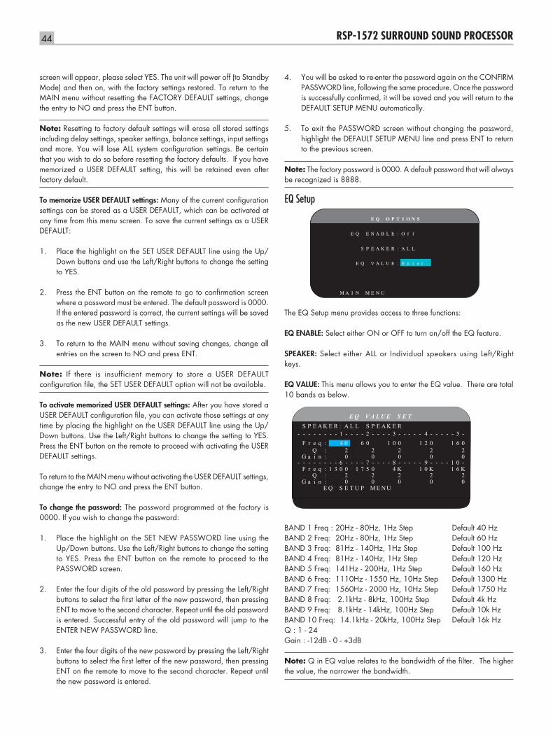
44 RSP-1572 SURROUND SOUND PROCESSOR
screen will appear, please select YES. The unit will power off (to Standby Mode) and then on, with the factory settings restored. To return to the MAIN menu without resetting the FACTORY DEFAULT settings, change the entry to NO and press the ENT button.
Note: Resetting to factory default settings will erase all stored settings including delay settings, speaker settings, balance settings, input settings and more. You will lose ALL system configuration settings. Be certain that you wish to do so before resetting the factory defaults. If you have memorized a USER DEFAULT setting, this will be retained even after factory default.
To memorize USER DEFAULT settings: Many of the current configuration settings can be stored as a USER DEFAULT, which can be activated at any time from this menu screen. To save the current settings as a USER DEFAULT:
Place the highlight on the SET USER DEFAULT line using the Up/1. Down buttons and use the Left/Right buttons to change the setting to YES.
Press the ENT button on the remote to go to confirmation screen 2. where a password must be entered. The default password is 0000. If the entered password is correct, the current settings will be saved as the new USER DEFAULT settings.
To return to the MAIN menu without saving changes, change all 3. entries on the screen to NO and press ENT.
Note: If there is insufficient memory to store a USER DEFAULT configuration file, the SET USER DEFAULT option will not be available.
To activate memorized USER DEFAULT settings: After you have stored a USER DEFAULT configuration file, you can activate those settings at any time by placing the highlight on the USER DEFAULT line using the Up/Down buttons. Use the Left/Right buttons to change the setting to YES. Press the ENT button on the remote to proceed with activating the USER DEFAULT settings.
To return to the MAIN menu without activating the USER DEFAULT settings, change the entry to NO and press the ENT button.
To change the password: The password programmed at the factory is 0000. If you wish to change the password:
Place the highlight on the SET NEW PASSWORD line using the 1. Up/Down buttons. Use the Left/Right buttons to change the setting to YES. Press the ENT button on the remote to proceed to the PASSWORD screen.
Enter the four digits of the old password by pressing the Left/Right 2. buttons to select the first letter of the new password, then pressing ENT to move to the second character. Repeat until the old password is entered. Successful entry of the old password will jump to the ENTER NEW PASSWORD line.
Enter the four digits of the new password by pressing the Left/Right 3. buttons to select the first letter of the new password, then pressing ENT on the remote to move to the second character. Repeat until the new password is entered.
You will be asked to re-enter the password again on the CONFIRM 4. PASSWORD line, following the same procedure. Once the password is successfully confirmed, it will be saved and you will return to the DEFAULT SETUP MENU automatically.
To exit the PASSWORD screen without changing the password, 5. highlight the DEFAULT SETUP MENU line and press ENT to return to the previous screen.
Note: The factory password is 0000. A default password that will always be recognized is 8888.
EQ Setup
E Q O P T I O N S
E Q E N A B L E : O f f
S P E A K E R : A L L
E Q V A L U E : E n t e r
M A I N M E N U
The EQ Setup menu provides access to three functions:
EQ ENABLE: Select either ON or OFF to turn on/off the EQ feature.
SPEAKER: Select either ALL or Individual speakers using Left/Right keys.
EQ VALUE: This menu allows you to enter the EQ value. There are total 10 bands as below.
E Q V A L U E S E TS P E A K E R A L L S P E A K E R
- - - - - - - - 1 - - - - 2 - - - - 3 - - - - - 4 - - - - - 5 -F r e q : 4 0 6 0 1 0 0 1 2 0 1 6 0
Q : 2 2 2 2 2G a i n : 0 0 0 0 0
- - - - - - - - 6 - - - - 7 - - - - 8 - - - - - 9 - - - - 1 0 -F r e q : 1 3 0 0 1 7 5 0 4 K 1 0 K 1 6 K
Q : 2 2 2 2 2G a i n : 0 0 0 0 0
E Q S E T U P ME N U
:
BAND 1 Freq : 20Hz - 80Hz, 1Hz Step Default 40 HzBAND 2 Freq: 20Hz - 80Hz, 1Hz Step Default 60 HzBAND 3 Freq: 81Hz - 140Hz, 1Hz Step Default 100 HzBAND 4 Freq: 81Hz - 140Hz, 1Hz Step Default 120 HzBAND 5 Freq: 141Hz - 200Hz, 1Hz Step Default 160 HzBAND 6 Freq: 1110Hz - 1550 Hz, 10Hz Step Default 1300 HzBAND 7 Freq: 1560Hz - 2000 Hz, 10Hz Step Default 1750 HzBAND 8 Freq: 2.1kHz - 8kHz, 100Hz Step Default 4k HzBAND 9 Freq: 8.1kHz - 14kHz, 100Hz Step Default 10k HzBAND 10 Freq: 14.1kHz - 20kHz, 100Hz Step Default 16k HzQ : 1 - 24Gain : -12dB - 0 - +3dB
Note: Q in EQ value relates to the bandwidth of the filter. The higher the value, the narrower the bandwidth.
45English
TroubleshootingMost difficulties in audio systems are the result of incorrect connections, or improper control settings. If you encounter problems, isolate the area of the difficulty, check the control settings, determine the cause of the fault and make the necessary changes. If you are unable to get sound from the unit, refer to the suggestions for the following conditions:
The unit does not turn onMake sure the power cord is plugged into the rear panel and a •AC outlet.
Make sure the rear panel POWER switch is in the ON position.•
No sound from any inputMake sure that MUTING is off and VOLUME is turned up.•
Make sure that preamp outputs are connected to a power amplifier •and that the amplifier is turned on.
Make sure source inputs are connected and configured correctly.•
Check that the setting for HDMI AUDIO in the VIDEO/HDMI on-•screen menu is AMP MODE.
No sound from digital sourcesMake sure that digital input connector is assigned to the proper •source input and that the source input is configured to use the digital input rather than an analog input.
Check the configuration of the DVD player to ensure that the bitstream •and/or DTS digital output is activated.
No sound from some speakers Check all power amp and speaker connections.•
Check Speaker Configuration settings in the Setup menus.•
No video output on TV monitor.Make sure that the TV monitor is connected properly and check the •input assignments. Composite Video TV monitors can only be used with interlaced SD sources. HDMI and Component TV monitors can be used with Standard Definition (SD) and High Definition (HD) sources. An HDMI 1080p source can only be sent to a 1080p-compliant TV monitor .
Component Video output at 720p or 1080i may not be available •if the source signal includes HDCP copy protection.
HDMI cables must be 5 meters or less in length.•
If watching 3D source, make sure the display is 3D enabled.•
Video and Audio do not match.Check that the proper video source is selected for each input.•
Check that the group delay (lip-synch) setting is not mis-adjusted.•
Clicking or popping sounds when switching inputsThe unit uses relay switching to preserve maximum sound quality. •The mechanical clicking of the relays is normal.
During switching, it may take a split second for digital signals to •be recognized and properly decoded. Rapid repeated switching between inputs or settings can result in clicks or pops from the speakers as the unit attempts to lock on to the rapidly changing signals. This causes no harm.
Switching between HDMI sources may cause delays as HDMI two •way communications “handshake” must be established between the source and display. The time required for the handshake varies from equipment.
Controls do not operateMake sure that fresh batteries are installed in the remote.•
Make sure that the IR sensor on the front panel is not blocked. Aim •the remote at the sensor.
Make sure the sensor is not receiving strong IR light (sunlight, •halogen lighting, etc.)
Unplug the unit from the AC outlet, wait 30 seconds, and plug it •back to reset.
No video from ZONE 2, 3 or 4Check ZONE SETUP configuration and ZONE video input setting •assigned and make sure that a video source is connected.
HDMI: Frequently Asked QuestionsWhat is HDMI?HDMI (High-Definition Multimedia Interface) is an advanced type of connection which carries both video and audio in a single cable. It is a modern digital replacement for older analog video connection standards such as Composite Video, S-Video and Component Video. This Rotel unit meets the latest version of HDMI specification, HDMI 1.3, and HDMI 1.4 with 3D support and Audio Return Channel.
What is the difference between HDMI and DVI?An earlier digital connection standard, DVI (Digital Visual Interface) can also be used for high-definition video signals by means of a suitable adaptor. However, unlike HDMI, the DVI connection does not also carry audio signals, nor does it automatically set the picture screen to the correct size.
What is the difference between HDMI 1.4, HDMI 1.3 and earlier versions?If you have a Blu-ray player, note that the HDMI 1.3 connection can carry the new Dolby TrueHD and DTS HD Master Audio formats used on Blu-ray discs. This processor is able to decode and replay these 7.1 channel audio formats. HDMI 1.4 includes additional features such as 3D video pass through for movies, games and broadcasts.
Also with Blu-ray, but depending on the monitor being used to view the picture, you may also be able to enjoy video enhancements such as Deep Color or XY video (also called Broad Color Space). Using the HDMI 1.4 connection, the RSP-1572 can pass these signals through from the Blu-ray player to a compatible monitor.
These new audio formats and video features are not available from standard DVD discs or players, even when an HDMI connection is used.
46 RSP-1572 SURROUND SOUND PROCESSOR
Can I connect components which have earlier versions of HDMI?Yes, because HDMI is backwards-compatible. This means that components which have earlier versions of HDMI (such as HDMI 1.1 or HDMI 1.2) will perform correctly when connected to the HDMI 1.4 inputs or outputs of the unit.
If your DVD player is equipped with HDMI 1.2a, the HDMI connection will permit the transmission of 1080p (high definition) video signals.
Which is the best way to rescale the picture?When using legacy components that require picture rescaling, it is better to use the monitor scaler to handle any picture resizing. You should try to use only one scaler in the system, so keep your DVD player set to 480p or 1080p. A 480p signal will be rescaled by the monitor and a 1080p signal will be seen by a monitor with 1080p resolution as a native signal.
Some Blu-ray and HD-DVD discs have been recorded in 1080i. These should not be scaled, but are best left to the monitor to interpret into an appropriate format for the screen.
Will the HDMI digital output improve the picture quality from old analog sources?Analog picture sources from legacy units begin by being less good than digital signals, and while the RSP-1572 will translate them into a digital format, the final quality will be constrained by the original source, and the choice of connection (Composite or Component). The scaler cannot correct for low resolution signals and will not improve inherently poor picture quality.
Why does the HDMI connection sometimes not give a picture?Although it is simple to use, the HDMI connection is actually a highly complex electrical circuit, and within it is a security system called HDCP (High Definition Content Protection). In some circumstances pictures may not reproduce, or may not reproduce properly, due to the action of DRM (Digital Rights Management) or the ‘handshake’ between the two connected units. HDMI cables contain circuits that exchange a ‘handshake’ signal several times a second, designed to maintain the integrity of the transmission signal and to prevent attempted unauthorized copying of copyright material. However, these ‘handshake’ signals can be disrupted for several reasons. If problems persist, consult your Rotel dealer.
47English
SpecificationsAudio
Total Harmonic Distortion <0.008%
Intermodulation Distortion (60Hz:7kHz) <0.008%
Frequency Response 10Hz - 120kHz, ±3dB (analog bypass) 10Hz - 95kHz, ±0.3dB (digital input)
Signal to Noise Ratio (IHF A-weighted) 95dB (analog bypass) 92dB (Dolby Digital, DTS) 0 dBFs
Input Sensitivity/Impedance Line Level: 200 mV/100k ohms
Preamp Output Level/Output Impedance 1.0V/1k ohms
Decodable Digital Input Signals Dolby Digital, Dolby Digital EX, DTS, DTS-ES, DTS 96/24, DTS-ES 96/24, LPCM (up to 192k). Lossless audio formats (using HDMI 1.3): Dolby TrueHD and DTS HD Master Audio.
Decodable USB/iPod Digital Input Signals AAC(m4a), WAV, MP3, WMA
Video
Input Resolutions 480i/576i, 480p/576p, 720p, 1080i 1080p, 1080p 24Hz, 3D (HDMI only)
Output Resolution 480i/576i (Composite only), 480p/576p, 720p, 1080i 1080p, 1080p 24Hz, 3D (HDMI only)
Signal to Noise Ratio 45dB
Input Impedance 75 ohms
Output Impedance 75 ohms
Output Level 1.0 volt
HMDI Inputs/Outputs Version 1.3, supporting Deep Color passthrough and Broad Color Space passthrough. Version 1.4, supporting 3D passthrough and Audio Return Channel
General
Power Consumption 60 watts 0.5 watt (standby)
Power Requirements (AC) 120 volts, 60Hz (USA version) 230 volts, 50Hz (EC version)
Weight 9.7kg/21.38lbs
Dimension (W x H x D) 431 x 143 x 338 mm 17 x 55/8 x 131/2 in
Front Panel Height (feet removed/for rack mount) 3U/132.6mm/51/4 in
When sizing openings in custom cabinets, measure the unit to be installed and/or allow at least 1mm clearance on all sides for unit to unit tolerances. All specifications are accurate at the time of printing. Rotel reserves the right to make improvements without notice
Rotel and the Rotel Hifi logo are registered trademarks of The Rotel Co., Ltd. Tokyo, Japan.
“Made for iPod,” and “Made for iPhone,” means that an electronic accessory has been designed to connect specifically to iPod or iPhone, respectively, and has been certified by the developer to meet Apple performance standards. Apple is not responsible for the operation of this device or its compliance with safety and regulatory standards. Please note that the use of this accessory with iPod, or iPhone may affect wireless performance.
iPhone, iPod, iPod classic, iPod nano, and iPod touch are trademarks of Apple Inc., registered in the U.S. and other countries.
082 OMRSP1572 070711 English
The Rotel Co. Ltd.Endo TN Building 2F.,6-12-21, Meguro-Honcho,Meguro-Ku, Tokyo 152-0002Japan
Rotel of America54 Concord StreetNorth Reading, MA 01864-2699USAPhone: +1 978-664-3820Fax: +1 978-664-4109
Rotel EuropeDale RoadWorthing, West Sussex BN11 2BHEnglandPhone: + 44 (0)1903 221 761Fax: +44 (0)1903 221 525
Rotel DeutschlandVertrieb: B&W Group Germany GmbHKleine Heide 12D-33790 Halle/Westf., DeutschlandTel.: 05201 / 87170Fax: 05201 / 73370E-Mail: [email protected]
www.rotel.com